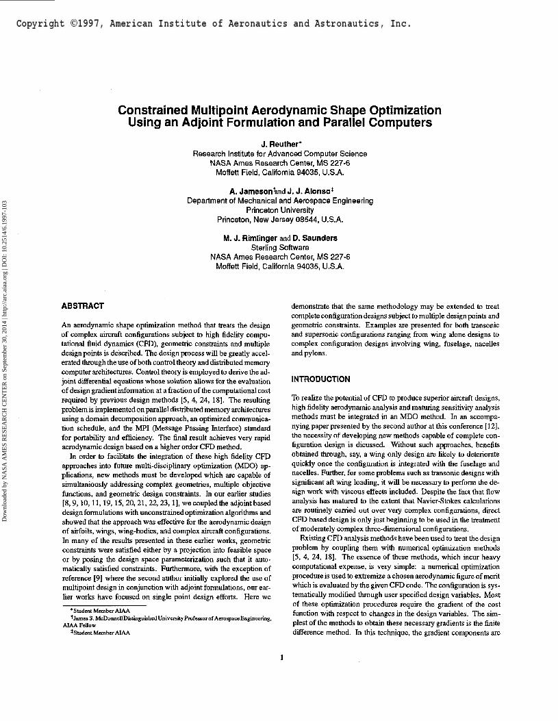
Copyright ©1997, American Institute of Aeronautics and Astronautics, Inc. AIAA Meeting Papers on Disc, January 1997 A9715191, AF-AFOSR-91-0391, N00014-92-J-1976, AIAA Paper 97-0103 Constrained multipoint aerodynamic shape optimization using an adjoint formulation and parallel computers J. Reuther NASA, Ames Research Center, Moffett Field, CA A. Jameson Princeton Univ., NJ J. J. Alonso Princeton Univ., NJ M. J. Rimlinger NASA, Ames Research Center, Moffett Field, CA D. Sauders NASA, Ames Research Center, Moffett Field, CA AIAA, Aerospace Sciences Meeting & Exhibit, 35th, Reno, NV, Jan. 6-9, 1997 An aerodynamic shape optimization method that treats the design of complex aircraft configurations subject to high fidelity CFD, geometric constraints and multiple design points is described. The design process will be greatly accelerated through the use of both control theory and distributed memory computer architectures. Control theory is employed to derive the adjoint differential equations whose solution allows for the evaluation of design gradient information at a fraction of the computational cost required by previous design methods. The resulting problem is implemented on parallel distributed memory architectures using a domain decomposition approach, an optimized communication schedule, and the MPI (Message Passing Interface) standard for portability and efficiency. The final result achieves very rapid aerodynamic design based on a higher order CFD method. Examples are presented for both transonic and supersonic configurations ranging from wing alone designs to complex configuration designs involving wing, fuselage, nacelles, and pylons. (Author) Page 1 Downloaded by NASA AMES RESEARCH CENTER on September 30, 2014 | http://arc.aiaa.org | DOI: 10.2514/6.1997-103

Welcome message from author
This document is posted to help you gain knowledge. Please leave a comment to let me know what you think about it! Share it to your friends and learn new things together.
Transcript
Copyright ©1997, American Institute of Aeronautics and Astronautics, Inc.
AIAA Meeting Papers on Disc, January 1997A9715191, AF-AFOSR-91-0391, N00014-92-J-1976, AIAA Paper 97-0103
Constrained multipoint aerodynamic shape optimization using an adjointformulation and parallel computers
J. ReutherNASA, Ames Research Center, Moffett Field, CA
A. JamesonPrinceton Univ., NJ
J. J. AlonsoPrinceton Univ., NJ
M. J. RimlingerNASA, Ames Research Center, Moffett Field, CA
D. SaudersNASA, Ames Research Center, Moffett Field, CA
AIAA, Aerospace Sciences Meeting & Exhibit, 35th, Reno, NV, Jan. 6-9, 1997
An aerodynamic shape optimization method that treats the design of complex aircraft configurations subject to high fidelityCFD, geometric constraints and multiple design points is described. The design process will be greatly accelerated throughthe use of both control theory and distributed memory computer architectures. Control theory is employed to derive theadjoint differential equations whose solution allows for the evaluation of design gradient information at a fraction of thecomputational cost required by previous design methods. The resulting problem is implemented on parallel distributedmemory architectures using a domain decomposition approach, an optimized communication schedule, and the MPI(Message Passing Interface) standard for portability and efficiency. The final result achieves very rapid aerodynamic designbased on a higher order CFD method. Examples are presented for both transonic and supersonic configurations ranging fromwing alone designs to complex configuration designs involving wing, fuselage, nacelles, and pylons. (Author)
Page 1
Dow
nloa
ded
by N
ASA
AM
ES
RE
SEA
RC
H C
EN
TE
R o
n Se
ptem
ber
30, 2
014
| http
://ar
c.ai
aa.o
rg |
DO
I: 1
0.25
14/6
.199
7-10
3
Constrained Multipoint Aerodynamic Shape OptimizationUsing an Adjoint Formulation and Parallel Computers
J. Reuther*Research Institute for Advanced Computer Science
NASA Ames Research Center, MS 227-6Moffett Field, California 94035, U.S.A.
A. Jameson'and J. J. Alonso*Department of Mechanical and Aerospace Engineering
Princeton UniversityPrinceton, New Jersey 08544, U.S.A.
M. J. Rimiinger and D. SaundersSterling Software
NASA Ames Research Center, MS 227-6Moffett Field, California 94035, U.S.A.
ABSTRACT
An aerodynamic shape optimization method that treats the designof complex aircraft configurations subject to high fidelity compu-tational fluid dynamics (CFD), geometric constraints and multipledesign points is described. The design process will be greatly accel-erated through the use of both control theory and distributed memorycomputer architectures. Control theory is employed to derive the ad-joint differential equations whose solution allows for the evaluationof design gradient information at a fraction of the computational costrequired by previous design methods [5, 4, 24, 18]. The resultingproblem is implemented on parallel distributed memory architecturesusing a domain decomposition approach, an optimized communica-tion schedule, and the MPI (Message Passing Interface) standardfor portability and efficiency. The final result achieves very rapidaerodynamic design based on a higher order CFD method.
In order to facilitate the integration of these high fidelity CFDapproaches into future multi-disciplinary optimization (MDO) ap-plications, new methods must be developed which are capable ofsimultaniously addressing complex geometries, multiple objectivefunctions, and geometric design constraints. In our earlier studies[8,9,10,11, 19,15, 20,21,22, 23,1], we coupled the adjoint baseddesign formulations with unconstrained optimization algorithms andshowed that the approach was effective for the aerodynamic designof airfoils, wings, wing-bodies, and complex aircraft configurations.In many of the results presented in these earlier works, geometricconstraints were satisfied either by a projection into feasible spaceor by posing the design space parameterization such that it auto-matically satisfied constraints. Furthermore, with the exception ofreference [9] where the second author initially explored the use ofmultipoint design in conjunction with adjoint formulations, our ear-lier works have focused on single point design efforts. Here we
* Student Member AIAA* James S. McDonnellDistinguishcdUnivcisityProfessorof Aerospace Engineering,
AIAA Fellow*Student Member AIAA
demonstrate that the same methodology may be extended to treatcomplete configuration designs subject to multiple design points andgeometric constraints. Examples are presented for both transonicand supersonic configurations ranging from wing alone designs tocomplex configuration designs involving wing, fuselage, nacellesand pylons.
INTRODUCTION
To realize the potential of CFD to produce superior aircraft designs,high fidelity aerodynamic analysis and maturing sensitivity analysismethods must be integrated in an MDO method. In an accompa-nying paper presented by the second author at this conference [12],the necessity of developing new methods capable of complete con-figuration design is dicussed. Without such approaches, benefitsobtained through, say, a wing only design are likely to deterioratequickly once the configuration is integrated with the fuselage andnacelles. Further, for some problems such as transonic designs withsignificant aft wing loading, it will be necessary to perform the de-sign work with viscous effects included. Despite the fact that flowanalysis has matured to the extent that Navier-Stokes calculationsare routinely carried out over very complex configurations, directCFD based design is only just beginning to be used in the treatmentof moderately complex three-dimensional configurations.
Existing CFD analysis methods have been used to treat the designproblem by coupling them with numerical optimization methods[5, 4, 24, 18]. The essence of these methods, which incur heavycomputational expense, is very simple: a numerical optimizationprocedure is used to extremize a chosen aerodynamic figure of meritwhich is evaluated by the given CFD code. The configuration is sys-tematically modified through user specified design variables. Mostof these optimization procedures require the gradient of the costfunction with respect to changes in the design variables. The sim-plest of the methods to obtain these necessary gradients is the finitedifference method. In this technique, the gradient components are
Dow
nloa
ded
by N
ASA
AM
ES
RE
SEA
RC
H C
EN
TE
R o
n Se
ptem
ber
30, 2
014
| http
://ar
c.ai
aa.o
rg |
DO
I: 1
0.25
14/6
.199
7-10
3
estimated by independently perturbing each design variable with afinite step, calculating the corresponding value of the objective func-tion using CFD analysis, and forming the ratio of the differences.The gradient is then used by the numerical optimization algorithmto calculate a search direction. After finding the minimum or maxi-mum of the objective function along the search direction, the entireprocess is repeated until the gradient approaches zero and furtherimprovement is not possible.
The finite-difference approach which has been historically usedto calculate the aerodynamic sensitivities is especially inappropriatewhen complex configurations, requiring hundreds or even thousandsof design variables, and multiple design points are to be consid-ered. Nevertheless, it is attractive when compared with other tra-ditional design strategies such as inverse methods, since it permitsany choice of the aerodynamic figure of merit. The use of numericaloptimization for transonic aerodynamic shape design was pioneeredby Hicks, Murman and Vanderplaats [5]. They applied the method totwo-dimensional profile design governed by the potential flow equa-tion. The method was quickly extended to wing design by Hicksand Henne [4]. Later, in the work of Reuther, Cliff, Hicks and VanDam, this method was successfully used for the design of supersonicwing-body transport configurations [18]. However all of these cases,which were confined to finite difference gradients on serial computerarchitectures, were limited in their geometric complexity simply dueto computational expense. For example, the designs presented in[18] were limited to wing-body configurations. Yet it is well knownthat optimum performance (especially for supersonicconfigurations)will require highly tuned nacelle/airframe integrations. It was notpossible to include nacelle/airframe considerations into the designproblem outlined in [18] since the required number of mesh points,which more than doubles with the inclusion of nacelles, could not beafforded.
Recently, through our own work and that of other groups, alterna-tive, less expensive methods for obtaining design sensitivities havebeen developed. These methods greatly reduce the computationalcosts of optimization. The most promising of these approaches is theadjoint formulation whereby the sensitivity at a single design pointwith respect to an arbitrary number of design variables is obtainedwith the equivalent of two flow calculations (one flow solution andone adjoint solution). Moreover, the adjoint solution (and to a lesserextent the accompanying flow solution) need not be highly con-verged to be useful, in significant contrast to the highly-convergedflow solutions which are crucial to accurate finite difference gradi-ents [25]. For the case of multiple design points, separate flow andadjoint solutions are needed for each design point. Thus, so longas the number of design points remains significantly smaller thanthe number of design variables the reduction in the computationaltime resulting from the employment of an adjoint approach will beconvincing.
In spite of the large decrease in computational cost provided byan adjoint formulation, the aerodynamic optimization of a completeconfiguration, especially with the inclusion of viscous effects ortaken in the context of even larger MDO problems, still remains aformidable computational task. The advent of reliable and efficientparallel computers using distributed memory is thus a key enablingtechnology for design calculations of complete aircraft configura-tions subject to multiple design conditions and for both linear andnonlinear constraints to be treated in an acceptable turnaround time.
The work presented in this paper combines the adjoint formulationand a parallel implementation such that objective function evalua-tions and aerodynamic sensitivities for any particular point in thedesign space may be calculated in a very short wall clock time. Thisapproach is then coupled to a constrained sequential quadratic pro-gramming (SQP) optimization algorithm [2]. Linear constraints aretreated by a projection into feasible space while nonlinear constraintsare addressed through an augmented Lagrangian approach.
FORMULATION OF THE ADJOINT EQUATIONS
The aerodynamic properties which define the cost function I at asingle design point are functions of the flow field variables, w, andthe physical location of the boundary, which may be represented bythe function f. Then
and a change in y results in a change
dw (1)
in the cost function. The governing equation R and its first variationexpress the dependence of w and T within the flow field domain D:
T = 0. (2)
Next, introducing a Lagrange multiplier ifi, we have
dIT , 5/T._ ,T HdR] , \dR] ._>= ——aw + ——tT — to I —— ow + —— SJ-dw df V L S t u J ldT\ J
dw
SI
Choosing •>!> to satisfy the adjoint equation
dR]T
T—aw J81
(3)
the first term is eliminated, and we find that the desired gradient isgiven by
QT = (4)
Since (4) is independent of Sw, the gradient of / with respect to anarbitrary number of design variables can be determined without theneed for additional flow field evaluations. The main cost is in solv-ing the adjoint equation (3). In general, the adjoint problem is aboutas complex as a flow solution. If the number of design variables islarge, it becomes compelling to take advantage of the cost differen-tial between one adjoint solution and the large number of flow fieldevaluations required to determine the gradient by finite differences.To treat the multipoint problem a composite cost function is devel-oped as a weighted sum of cost functions at each independent designpoint:
1=\\l\where Ai and A2 are the relative weights of the two cost functionsat different design points. The composite gradient is then obtainedby taking the same weighted sum of the gradients developed by theabove procedure for each point.
Dow
nloa
ded
by N
ASA
AM
ES
RE
SEA
RC
H C
EN
TE
R o
n Se
ptem
ber
30, 2
014
| http
://ar
c.ai
aa.o
rg |
DO
I: 1
0.25
14/6
.199
7-10
3
MULTIBLOCK FLOW SOLUTION
In our most recent papers [17,23] the adjoint based design formula-tion was extended for the Euler equations to treat complete aircraftconfigurations via a new multiblock implementation. This extensionof the method from that presented in our earlier three-dimensionalwork required the replacement of the single block flow and adjointsolvers [10, 20, 22] with their multiblock counterparts. During thedevelopment of the new multiblock flow solver, care was taken tosatisfy additional demands that design methods place upon analysisalgorithms.
In order to use CFD in an automated design environment, the flowsolver must meet fundamental requirements of accuracy, efficiency,and robust convergence. High accuracy is required since the pre-dicted improvements in the design realized by the method can onlybe as good as the accuracy of the flow analysis. Efficiency of the flowsolver is also critical since the optimization of the design will gener-ally require the computation of many flow solutions or other solutionsof comparable complexity. The last aspect, robust convergence, isalso of significant importance. In highly refined aerodynamic de-sign applications, (he main benefit of aerodynamic optimization is inobtaining the last few percentage points in improved efficiency. Insuch cases the solutions must be highly converged so that the noisein the figure of merit, say drag at a fixed lift, is well below the levelof realizable improvement.
In our three-dimensional single block applications, the FLO87code written bythesecond author easily met all of the above criteria.FLO87 achieves fast convergence with the aid of multigridding andresidual smoothing. It is normally easy to obtain solutions thatconverge to machine accuracy. The challenge in reference [23] wasto meet these strict convergence requirements within the frameworkof a multiblock flow solver. The usage of a multiblock flow solutionis the first step towards the treatment of more complex configurations.However, the use of the multiblock strategy to treat the complexconfigurations that are presented in this paper is not the only viableapproach. Other alternatives, such as unstructured mesh solvers, arealso currently under investigation.
The general strategy in developing the multiblock flowsolveristoconstruct and update a halo of cells around each block such that theflow solution inside each block is transparent to the block boundaries.This task requires establishing the size and location of halo cellsadjacent to block boundaries, and loading the halo cell values withappropriate flow field data at the appropriate times. To accomplishthis task, a two-level halo is constructed around each block. Therequirement of this double halo results from the necessity of keepinga complete stencil of calculated fluxes entering and leaving eachcell in the entire domain without regard to block boundaries. Sinceboth the convective and the dissipative fluxes are calculated at thecell faces (boundaries of the control volumes), all six neighboringcells are necessary, thus requiring the existence of a single levelhalo for each block in the multiblock calculation. The dissipativefluxes are composed of a blend of first and third order differencescorresponding to terms that mimic second and fourth derivativesof the flow quantities [16]. This requires a second layer of halocells at each block interface. Halo cells on the external boundaryof the entire computational domain are constructed and updated byextrapolation and reflection. Coarse grids are computed in the usualfashion, by aggregating groups of eight cells and then repeating
the above halo cell process. Once the halo configuration is set upfor each block, standard methods for spatial discretization and timeintegration (including artificial dissipation, residual averaging, andmultigridding) are employed to compute the flow solution withineach individual block.
The system of equations solved here as well as the solution strategyfollows that presented in many earlier works [16, 7, 6]. The three-dimensional Euler equations may be written as
(5)
where it is convenient to denote the Cartesian coordinates and ve-locity components by n, 12, £3 and MI, ui, us, and w and /< are
defined aspu,
-f- pSi3
with Sij being the Kronecker delta function. Also,
(6)
= (7 -
andpH = pE + p
(7)
(8)where 7 is the ratio of the specific heats. Consider a transformationto coordinates |i, £2, £3 where
Introduce scaled contravariant velocity components as
whereQ = JK~\
The Euler equations can now be written as
(9)
with
W- J 4
ppu\
pU2
pas
pE )
pU{u\ -f
(10)
For the multiblock case, the above notation applies to each blockin turn. The flow is thus determined as the steady-state solution toequation (9) in all blocks subject to the flow tangency conditions onall solid boundary faces of all blocks:
Un = 0 on all Bs (11)
Dow
nloa
ded
by N
ASA
AM
ES
RE
SEA
RC
H C
EN
TE
R o
n Se
ptem
ber
30, 2
014
| http
://ar
c.ai
aa.o
rg |
DO
I: 1
0.25
14/6
.199
7-10
3
where t] is 1, 2, or 3 depending on the direction that is normal toface Bs where a solid surface is assumed to exist At the far fieldboundary faces, BF, freestream conditions are specified for incom-ing waves, while outgoing waves are determined by the solution.
The time integration scheme follows that used in the single blockstrategy [16]. The solution proceeds by performing the cell fluxbalance, updating the flow variables, and smoothing the residuals, ateach stage of the time stepping scheme and each level of the multigridcycle. The main difference in the integration strategy is the need toloop over all blocks during each stage of the integration process. Theuse of the double-halo configuration permits standard single-blocksubroutines to be used, without modification, for the computation ofthe flow field within each individual block. This includes the single-block subroutines for convective and dissipative flux discretization,multistage time stepping, and multigrid convergence acceleration.
The only difference between the integration strategies is in theimplementation of the residual averaging technique. In the single-block solution strategy, a tridiagonal system of equations is set upand solved using flow information from the entire grid. Thus, eachresidual is replaced by a weighted average of itself and the residualsof the entire grid. In the multiblock strategy, the support for theresidual smoothing is reduced to the size of each block, in orderto eliminate the need to solve scalar tridiagonal systems spanningthe blocks, which would incur a penalty in communication costs.This change has no effect on the final converged solution, and inthe present application has not led to any reduction in the rate ofconvergence.
THE ADJOINT FORMULATION FOR THE EULER EQUA-TIONS
The application of control theory to aerodynamic design problemsis illustrated by treating the case of three-dimensional design, usingthe Euler equations discussed above as the mathematical model forcompressible flow. In our previous work, the illustrative problemmost often used specified the cost function as a measure of the differ-ence between the current and some desired pressure distribution. Inthe case of transonic flows over conventional commercial transportwings this aerodynamic figure of merit proves to be very effectivesince the tailoring of these pressure distributions to achieve closeto optimum performance is well understood by most aerodynami-cists. However, for either the case of supersonic design of three-dimensional configurations or designs which involve complicatedgeometries the specification of pressure distributions that will deter-mine near optimum performance is considerably more challenging.Therefore, from the outset of our development of the adjoint formu-lation, many different cost functions or their combinations have beenallowed. Here, for illustrative purposes we will use drag at a fixedlift as the cost function.
1= CD
CA cos a sn a
= - —— / / CP (Sx cos a + Sy sin a) dfr d&,sref J JBS
where Sx and Sy define projected surface areas, Sref is the referencearea, and dfi and d& are the two coordinate indices that are in theplane of the face in question. Note that the integral in the final
expression above is carried out over all solid boundary faces. Thedesign problem is now treated as a control problem where the controlfunction is the geometry shape, which is chosen to minimize /,subject to the constraints defined by the flow equations (5-10). Avariation in the shape will cause a variation 8p in the pressure andconsequently a variation in the cost function
crSI = — —da
where 6Ci> is the variation due to changes in the design parameterswith a fixed. To treat the interesting problem of practical design,drag must be minimized at a fixed lift coefficient. Thus an additionalconstraint is given by
6CL = 0,which gives
= 0
(12)
Combining these two expressions to eliminate See gives
SI = 6CDV Sa
0Since p depends on w through the equation of state (7-8), the varia-tion Up can be determined from the variation 8w. If a fixed computa-tional domain is used, the variations in the shape result in variationsin the mapping derivatives. Define the Jacobian matrices
dw' ' '13-
Then the equation for Sw in the steady state becomes
where in the domain
and on the solid surface,
0
(13)
(14)
6(Q+) on any Bs-
(15)
Now, multiplying equation (14) by a vector co-state variable ij>,assuming the result is differentiable, and integrating by parts overthe entire domain,
' = 0.^STSFi] d^ ~ Ia?t / JBwhere hi are components of a unit vector normal to the boundary.Equation (16) can now be subtracted from equation (12) withoutchanging the value of 61. Then •<!> may be chosen to cancel the
Dow
nloa
ded
by N
ASA
AM
ES
RE
SEA
RC
H C
EN
TE
R o
n Se
ptem
ber
30, 2
014
| http
://ar
c.ai
aa.o
rg |
DO
I: 1
0.25
14/6
.199
7-10
3
explicit terms in 6w and 6p. For this purpose 1/1 is set to the steady-state solution of the adjoint equation
(17)
with the surface boundary condition
where
= Q on all Bs, (18)
C = { (So: cos a + Sy sin a)
v cos a — Sx sin a) } .
At internal block boundaries, the face integrals cancel from theadjacent blocks. At the far field the choice of the adjoint boundaryconditions depends on whether the flow is subsonic or supersonic.For subsonic flow, so long as the outer domain is very far from theconfiguration of interest, we may set
V>i_5 =0 on all Bp.
It is noted that the waves in the adjoint problem propagate in theopposite direction to those in the flow problem due to the transposein equation (17).
Finally we obtain the expression
SI = — —— II Cp{ (6SX cos a + SSV sin a)sref J JBS
+ii (sSy cos a - SSX sin a) } dfr
(19)
Details of the approach as well as the development for other costfunctions have been presented in references [10, 11, 15,20,21,23].
MULTIBLOCK MESH VARIATIONS
In order to construct SI in equation (19), the variation in the metricterms must be obtained in each block. One way to accomplish this isto use finite differences to calculate the necessary information. Thisapproach avoids the use of multiple flow solutions to determine thegradient, but it unfortunately still requires the mesh generator to beused repeatedly. The number of mesh solutions required is propor-tional to the number of design variables. The inherent difficulty inthe approach is two-fold. First, for complicated three-dimensionalconfigurations, elliptic or hyperbolic partial differential equationsmust often be solved iteratively in order to obtain acceptably smoothmeshes. These iterative mesh generation procedures are often com-putationally expensive. In the worst case they approach the cost ofthe flow solution process. Thus the use of finite difference meth-ods for obtaining metric variations in combination with an iterativemesh generator leads to computational costs which strongly hinge onthe number of design variables, despite the use of an adjoint solverto eliminate the flow variable variations. Second, multiblock meshgeneration is by no means a trivial task. In fact no method currentlyexists that allows this to be accomplished as a completely automaticprocess for complex three-dimensional configurations.
In our earlier works [20, 19, 15, 8, 9, 10], two methods havebeen explored which avoid these difficulties. In the first method,a completely analytic mapping procedure was used for the meshgeneration. This technique is not only fully automatic and results insmooth consistentmeshes, butit also allows for completeeliminationof finite difference information for the mesh metric terms. Sincethe mapping function fully determines the entire mesh based on thesurface shape, this analytic relationship may be directly differentiatedin order to obtain the required information without considering afinite step. An analytic mapping method requires the geometrytopology to be built directly into the formulation, and only works forsimple configurations. Nevertheless, within these limitations it hasproven to be highly effective [8, 9, 10].
The second method that we have explored is the use of an analyticmesh perturbation technique. In this approach, a high quality meshappropriate for the flow solver is first generated by any availableprocedure prior to the start of the design. In examples to be shownlater, these meshes were created using the Gridgen software devel-oped by Pointwise, Inc.[26]. This initial mesh becomes the basisfor all subsequent meshes which are obtained by analytical pertur-bations. In the method that was initially developed for wing-bodyconfigurations it had been assumed that only one surface, say thewing, was perturbed during a design case. This permitted the use ofa very simple algebraic mesh perturbation algorithm. New mesheswere created by moving all the mesh points on an index line project-ing from the surface by an amount which was attenuated as the arclength from the surface increased. If the outer boundary of the griddomain is held constant the modification to the grid has the form
old , f»o+ S old\ (20)
where x,• represents the volume grid points, i s; represents the surfacegrid points and S represents the arc length along the radial mesh linemeasured from the outer domain, normalized so that S = 1 at theinner surface. Unfortunately this simple logic breaks down in thecase where multiple faces sharing common edges are allowed tomove. Thus in order to use analytic mesh perturbations for thetreatment of the more general problem where multiple faces of agiven block may be simultaneously deformed, equation (20) had tobe modified in a way that resembles transflnite interpolation (TFI)[27]. Unlike TFI, where there is no prior knowledge of the interiormesh, the perturbation algorithm developed here (WARP3D) doesmake use of the relative interior point distributions in the initial mesh.
The WARP3D algorithm has been modified from that presentedin reference [23] and is now a three stage procedure [17]. The firststage shifts the internal mesh points to produce an interim block thatis determined entirely by the new locations of the 8 corner pointsdefining the block. The second stage corrects the perturbationsresulting from the first stage by determining the distance each ofthe 12 edges of the stage 1 block needs to be moved to attain thedesired edge locations. Finally with both corner and edge pointmotion accounted for, the third stage corrects the internal points forthe relative motion of the six faces.
Since our current flow solver and design algorithm assume a point-to-point match between blocks, each block may be independentlyperturbed by WARP3D, provided that perturbed surfaces are treatedcontinuously across block boundaries. The entire method of creatinga new mesh is given by the following algorithm.
1. All faces that are directly affected by the design variables (active
Dow
nloa
ded
by N
ASA
AM
ES
RE
SEA
RC
H C
EN
TE
R o
n Se
ptem
ber
30, 2
014
| http
://ar
c.ai
aa.o
rg |
DO
I: 1
0.25
14/6
.199
7-10
3
faces) are explicitly perturbed.
2. All edges that touch an active face, either in the same block orin an adjacent block, are implicitly perturbed by (20).
3. All inactive faces that either include an implicitly perturbededge or abut to an active face are implicitly perturbed by aquasi-3D form of WARP3D.
4. WARP3D is used on each block that has one or more explicitlyor implicitly perturbed faces to determine the adjusted interiorpoints.
Note that much of the mesh, especially away from the surfaces, willnot require mesh perturbations and thus may remain fixed throughthe entire design process. Close to the surfaces, many blocks willeither contain an active face or touch a block which contains anactive face, either by an edge or by a comer. As the design variationsaffect the active faces, the above scheme ensures that the entire meshwill remain attached along block boundaries. Added complexity isneeded to accomplish step (2) since the connectivity of the variousedges and corners must be indicated somehow. Currently, pointersto and from a set of master edges and master corners are determinedas a preprocessing step. During the design calculation, deflectionsto any edges or corners are fed to these master edges and mastercorners which in turn communicate these changes to all connectededges and corners.
Since this mesh perturbation algorithm is analytic it is possibleto work out the analytical variations in the metric terms requiredfor equation (19). This approach was followed in [20]. Howeversince the mesh perturbation algorithm that was used in the currentpaper was significantly more complex, and it was discovered thatthe computational cost of repeatedly using the block perturbationalgorithm was within reason, finite differences were used to calculateSQij instead of deriving the exact analytical relationships.
DESIGN VARIABLES AND CONSTRAINED OPTIMIZATION
It remains to choose design variables and impose constraints. In ourearlier work, where the analytic mesh mapping strategy was used,each point of the surface mesh served as a design variable. Thistechnique combined with smoothing and projecting into feasiblespace of the resulting gradient has proven to be highly effective forsingle-block design cases [8, 9,10,11,15,19,20].
Alternatively, geometric design variables and constraints may beprovided for selection by the designer to allow greater control overthedesignprocess. To develop this strategy, themultiblock approachhas been coupled to the NPSOL algorithm of Gill, Murray, Saun-ders, and Wright [2]. NPSOL is a sequential quadratic programming(SQP) method in which the search direction is calculated by solvingthe quadratic subproblem where the Hessian is defined by a quasi-Newton approximation of an augmented Lagrangian merit function.The Lagrange multipliers in this merit function serve to scale the ef-fect of any nonlinear constraints that the design may contain. Linearconstraints are treated by solving the quadratic subproblem such thatthe projected search direction remains in feasible space. A completetreatment of the method and other optimization strategies is given byGill, Murray, and Wright [3].
The primary control upon which the entire design process revolvesis the variation in the aerodynamic surf aces. This is readily apparent
from the developmentof the adjoint approach. Thus it is at the levelof surface variations that the coupling with NPSOL is accomplished.Realizing that aircraft configurations are composed of separate en-tities (wings, fuselages, nacelles, etc.) upon which constraints areimposed, an underlying set of geometry entities acts as a starting in-put for the design process. Next, the user-specified design variablesare allowed to act independently upon any of these geometry enti-ties. Linear and nonlinear geometric constraints are also evaluatedon these primary geometry entities. At any particular point in thedesign process, changes to the mesh surfaces are obtained by firstintersecting all of the geometry entities to construct a set of paramet-ric surfaces representing the complete configuration. The locationof each surface mesh point on this parametric representation is de-termined for the initial configuration in a preprocessing step. Theperturbed surface mesh point locations are determined by evaluatingthe parametric geometry surfaces at these predetermined locations.Once the surface mesh points have been updated, the volume meshmay be perturbed and either the gradient or the solution calculated.The important feature of this approach is that a set of simple geometryentities lies at the core of the entire design process. This techniqueretains the typical way in which aerodynamic vehicles are defined,and provides strict control over how, say, wing/body intersections aretreated. Furthermore, since the chosen design variables act directlyupon the geometry entities, at the end of the design process theseentities may be output for future analysis.
In the current implementation, the input geometry entities arerestricted to those defined by sets of points. However, in the future,CAD entities such as NURBS surfaces will also serve in this role,thereby allowing both the input and the output from the aerodynamicsurface optimization to interface directly with a CAD database.
DOMAIN DECOMPOSITION AND PARALLEL IMPLEMEN-TATION
The main strategies that are used to accomplish the parallelizationof the design code are: a domain decomposition model, a SPMD(Single Program Multiple Data) strategy, and the MPI (MessagePassing Interface) library for message passing. The choice of MPIwas determined by the requirement that the resulting code be portableto different parallel computing platforms as well as to homogeneousand heterogeneous networks of workstations.
As one can see from the previous sections, obtaining the desiredparallelization by domain decomposition entails the treatment of fourseparate parts: the solution of the flow equations, the solution of theadjoint equations, the calculation of the mesh perturbations, and thecalculation of the gradient integral formulas. No attempt is made toparallelize the constrained SQP optimization algorithm or the calcu-lation of the changes to the underlying geometry entities. It is thusassumed in this context that the determination of the step sizes andsearch directions provided by the optimization algorithm is com-putationally insignificant when compared with the other elementsnecessary during the design. '
Since the flow and adjoint equations are to be solved using ex-actly the same efficient numerical techniques, the same paralleliza-tion techniques used for the flow equations apply to the solutionof the adjoint equations. Therefore, all details of the parallel im-plementation corresponding to these first two parts of the programare identical. Furthermore, since the mesh perturbation algorithm
Dow
nloa
ded
by N
ASA
AM
ES
RE
SEA
RC
H C
EN
TE
R o
n Se
ptem
ber
30, 2
014
| http
://ar
c.ai
aa.o
rg |
DO
I: 1
0.25
14/6
.199
7-10
3
WARP3D also works on a block-by-block basis, the communicationnecessary to maintain mesh consistency can also be addressed bythe same domain decomposition strategies that are used for the stateand costate fields. The essential details of this decomposition strat-egy and parallel implementation as well as some calculated parallelspeed-ups can be found in [17].
COMPLETE MULTIBLOCK DESIGN ALGORITHM (SYN87-MB)
With all the necessary components defined for the multiblock adjoint-based design, it is now possible to outline the complete procedure:
1. Decompose the multiblock mesh into an appropriate number ofprocessors, and create lists of pointers for the communicationof the processor halo cells.
2. Solve the flow field governing equations (5-10) for each designpoint.
3. Solve the adjoint equations (17) subject to the boundary condi-tion (18) for each design point
4. For each of the n design variables repeat the following:
• Perturb the design variable by a finite step to modify thegeometry entities.
• Reintersect the geometry entities to form parametric ge-ometry surfaces.
• Explicitly perturb all face mesh points affected by thegeometry changes by evaluating their locations on theparametric geometries.
• Implicitly perturb all faces that share an edge with anexplicitly perturbed face.
• Obtain the new internal mesh point locations viaWARP3D for those blocks with perturbed faces.
• Calculate all the delta metric terms, SQij, within thoseblocks that were perturbed by finite differencing.
• Integrate equation (19) to obtain SI for those blocks thatcontain nonzero SQi,j, and for each design point, to de-termine the gradient component
5. Calculate the search direction via NPSOL and perform a linesearch.
6. Return to (2) if a minimum has not been reached.
The basic method here builds on that used in [20] with the properextensions to treat multiblock domains. In order to implement themethod, equation (17) and boundary condition (18) must be dis-cretized on the multiblock domain. In the current implementation, acell centered, central difference stencil that mimics the flux balancingused for the flow solution is used. Since this choice of discretizationdiffers from the one obtained if the discrete flow equation Jacobianmatrix were actually transposed to form the adjoint system, the gra-dients obtained by the present method will not be exactly equal tothe gradients calculated by finite differencing the discrete flow so-lutions. However, as the mesh is refined these differences shouldvanish. Continuing, the adjoint system so discretized is solved on
the multiblock domain in a fashion identical to that used for theflow solution. Therefore, the adjoint solver, like the flow solver,uses an explicit multistage Runge-Kutta-like algorithm acceleratedby residual smoothing and multigridding. Intra-block communica-tion is again handled through a double halo which allows for the fulltransfer of information across boundaries except for the stencil ofsupport for the implicit residual smoothing.
Step (4) in the above procedure is the portion of the method that isstill treated by finite differences. Fortunately, all of these steps incura small computational cost compared with a single flow analysis.It is therefore possible, without significant penalty, to leave this infinite difference form even for cases where many hundreds of designvariables are used.
NUMERICAL TESTS AND RESULTS
Numerical results will be presented for three classes of problems todemonstrate the versatility of our methods. Reference [23] gives atreatment of the reliability of the flow solver as well as the ability ofthe adjoint method to provide accurate gradients very efficiently. Theparallel speed-ups attained by the method have been demonstratedin [13,17].
Transonic Multipoint Wing DesignThe first test case explores the viability of using multipoint aerody-namic design for an isolated wing configuration under transonic flightconditions. The version of the adjoint based design code, originallypresented by the second author [10, 11], is used as a test bed for themultipoint design. The design variables were the 4,224 surface gridpoints on the wing, each of which was free to move in the normaldirection. The test case wing has a unit-semi-span, with 38 degreesleading edge sweep. The wing has a modified trapezoidal planform,with straight taper from a root chord of 0.38 to a tip chord of 0.10.The wing has an aspect ratio of 9.0 and a curved trailing edge in theinboard region blending into straight taper outboard of the 30% spanstation. The initial wing sections were based on an airfoil speciallydesigned by the second author's two dimensional design method [8]to give shock free flow at Mach 0.78 with a lift coefficient of 0.6.This section, which has a thickness to chord ratio of 9.5%, was usedat the tip. Similar sections with increased thickness and reducedcamber were used inboard. The variation of thickness was nonlin-ear with a more rapid increase near the root, where the thickness tochord ratio of the basic section was multiplied by a factor of 1.44.The inboard sections were rotated upwards to give the initial wing 6degrees of twist from root to tip.
The two-dimensional pressure distribution of the starting airfoil atits design point was introduced as a target pressure distribution uni-formly across the span. This target is presumably not realizable sinceit would imply a lifting wing with zero vortex drag, but it serves tofavor the establishment of a relatively benign pressure distribution.The total inviscid drag coefficient, due to the combination of vortexand shock wave drag, was also included in the cost function. Calcu-lations were performed with the lift coefficient forced to approach afixed value by adjusting the angle of attack every fifth iteration of theflow solution. A grid with 192x32x48 = 294,912points was used.
Figures (1 - 7), show the results of the multipoint calculation ata Mach number of 0.85 and three different design lift coefficients
Dow
nloa
ded
by N
ASA
AM
ES
RE
SEA
RC
H C
EN
TE
R o
n Se
ptem
ber
30, 2
014
| http
://ar
c.ai
aa.o
rg |
DO
I: 1
0.25
14/6
.199
7-10
3
(0.500,0.525 and 0.550). The plots show the initial wing geometryand pressure distribution, and the modified geometry and pressuredistribution after 60 designcycles. Table 1 summarizes the predictedreduction in the total inviscid drags at the three design points. As is
CL0.5000.5250.550
Initial CD0.01560.01730.0191
Final CD0.01140.01230.0135
Table 1: Drag reduction at three different design points
evident in the figures the shock strengths have been greatly reducedwith most of the wing displaying shock free conditions at all threedesign points. At the low CL design point there is a very weakincipient double shock pattern, and at the high lift design point thereis a very weak single shock. Single point optimization at CL = 0.500and 0.550 yielded drag coefficients of 0.0112 and 0.0133, so thecompromise wing is within 2 drag counts of both point optimizedwings at their design points.
Transonic Constrained Aircraft DesignAs a first demonstration of the multiblock optimization algorithm, atypical transonic business jet configuration is considered. The samegeometry was also studied in [23, 1].
The initial multiblock mesh about the business jet wing, body,and nacelle has 72 blocks and 750K cells. The underlying geometryentities that are eligible for design changes include a wing withsix defining stations and a fuselage. The initial configuration wasdesigned for Mach = 0.8 and CL = 0.3.
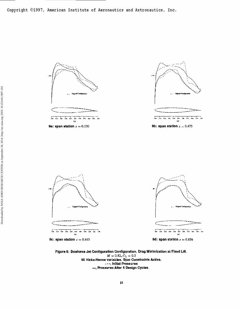
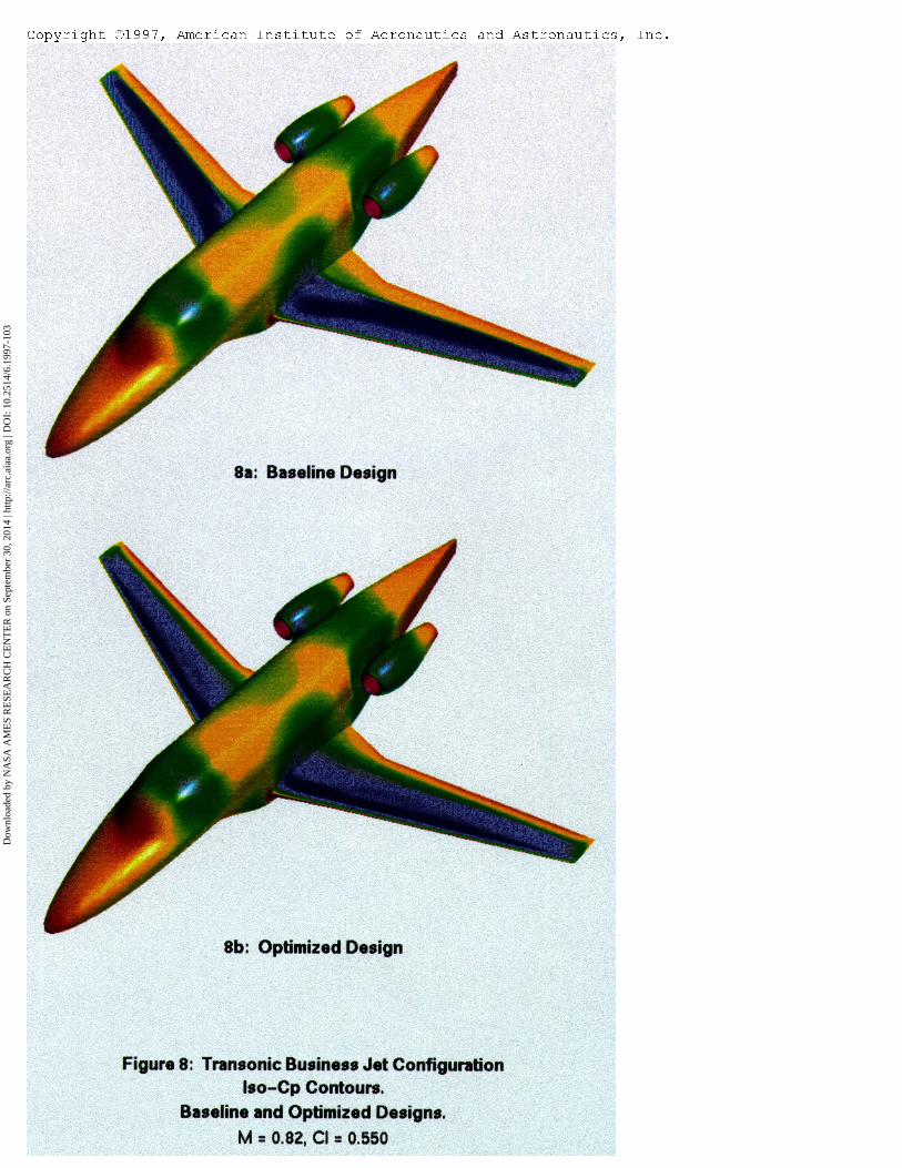
fri the first design case (Test Case 1), a single point constraineddesign is attempted in which the Mach number is pushed to 0.82.The objective is to minimize configuration pressure drag at a fixedlift coefficient of 0.3 by modifying the wing shape. Eighteen Hicks-Henne design variables are chosen for five of the six defining sectionsfor a total of 90 design variables. (The section at the symmetryplane is not being modified.) Spar thickness constraints were alsoenforced at each defining station at x/c = 0.2 and x/c = 0.8.Maximum thickness was forced to be preserved at x/c = 0.4 for allsix defining sections. Each section was also constrained to have thethickness preserved at x/c = 0.95 to ensure an adequate includedangle at the trailing edge. A total of 30 linear geometric constraintswere imposed on the configuration. Figure (8) shows an iso-Cpcolored representation of the initial design and the final design after5 NPSOL design iterations. It is clearly seen that the rather lowCp region terminated by a strong shock spanning the entire wingupper surface has been largely eliminated in the final design. Figure(9) shows overlays of the Cp distributions for the initial and finaldesigns at four stations along the wing. It is seen that the final resulthas reached a near-shock-free condition over much of the outboardwing panel. The drop in configuration pressure drag for this casewas 22.5%. Noting that most of this drag reduction came from adecrease in wing wave drag implies that further improvements maybe possible through the reshaping of other components.
In a second design example for this business jet configuration, amultipoint design is attempted. The three design points are Mach =
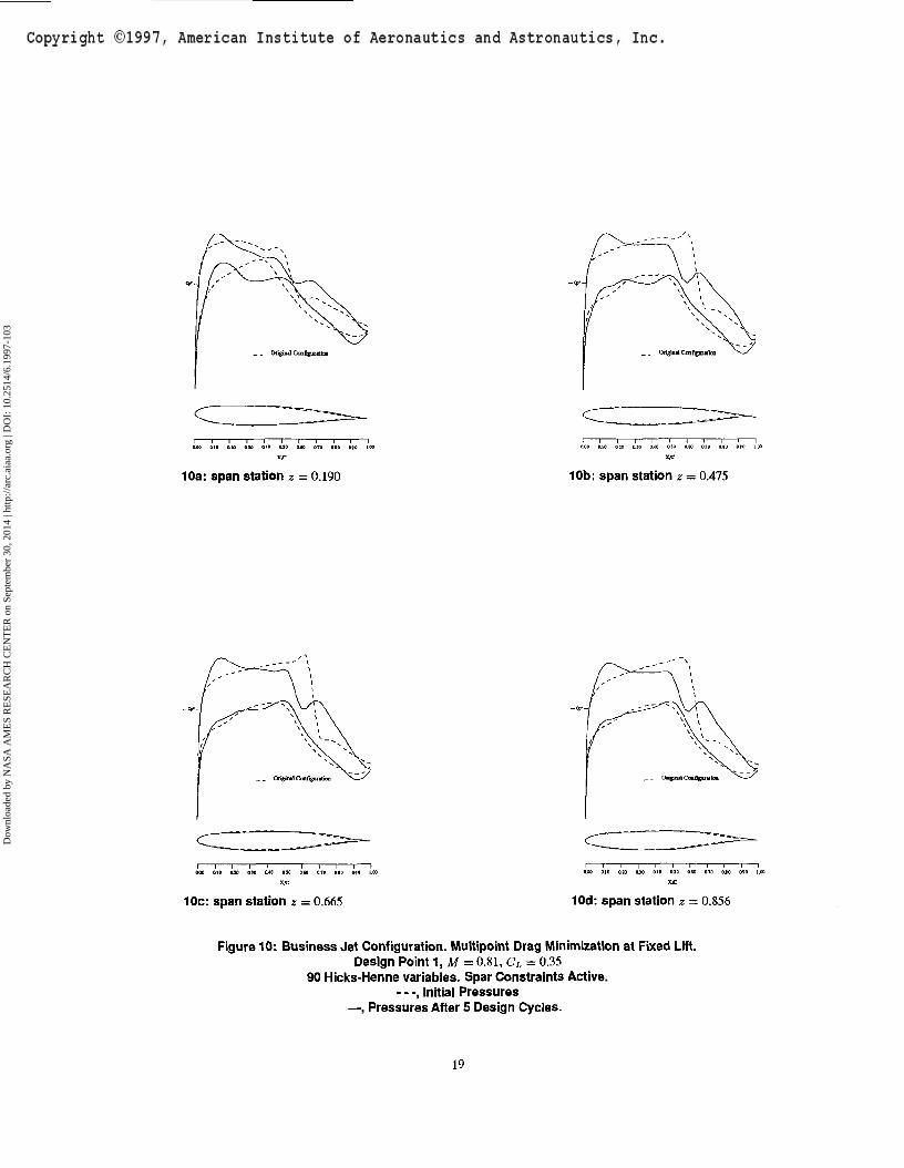
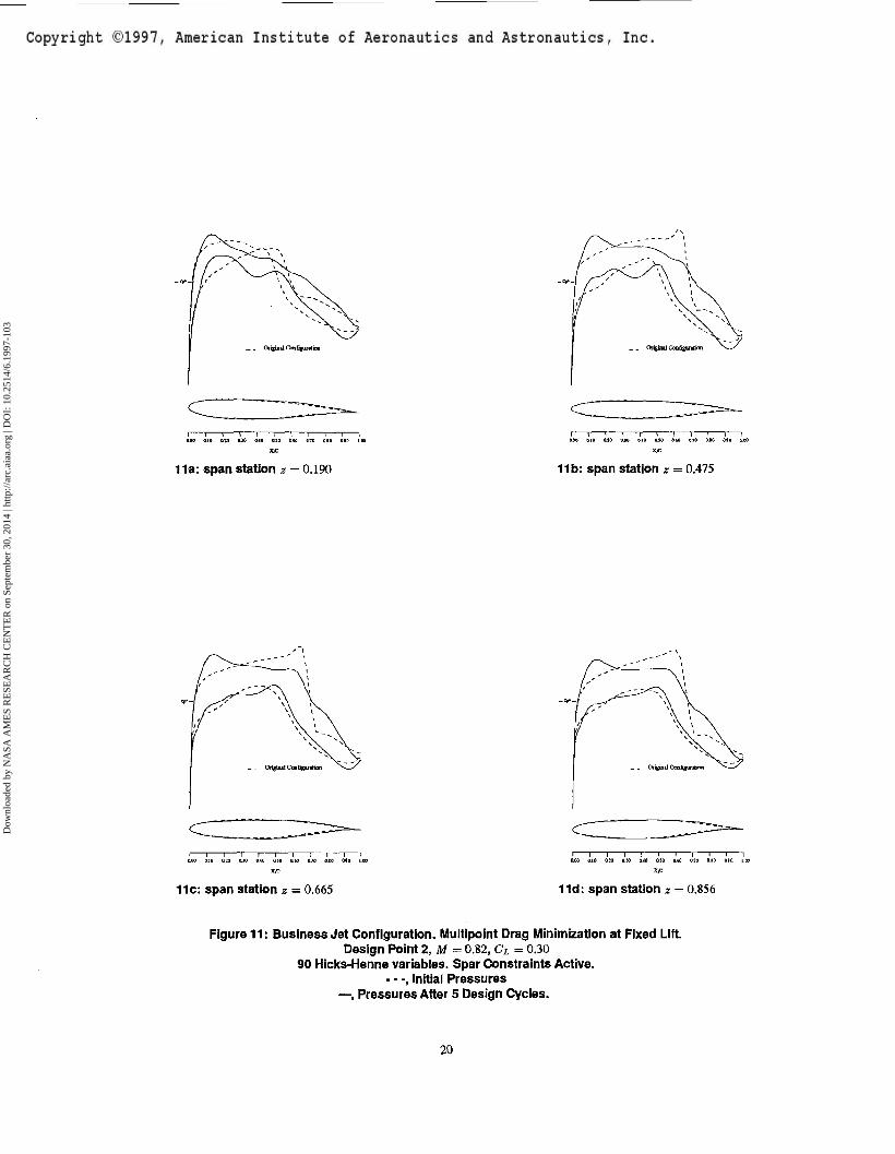
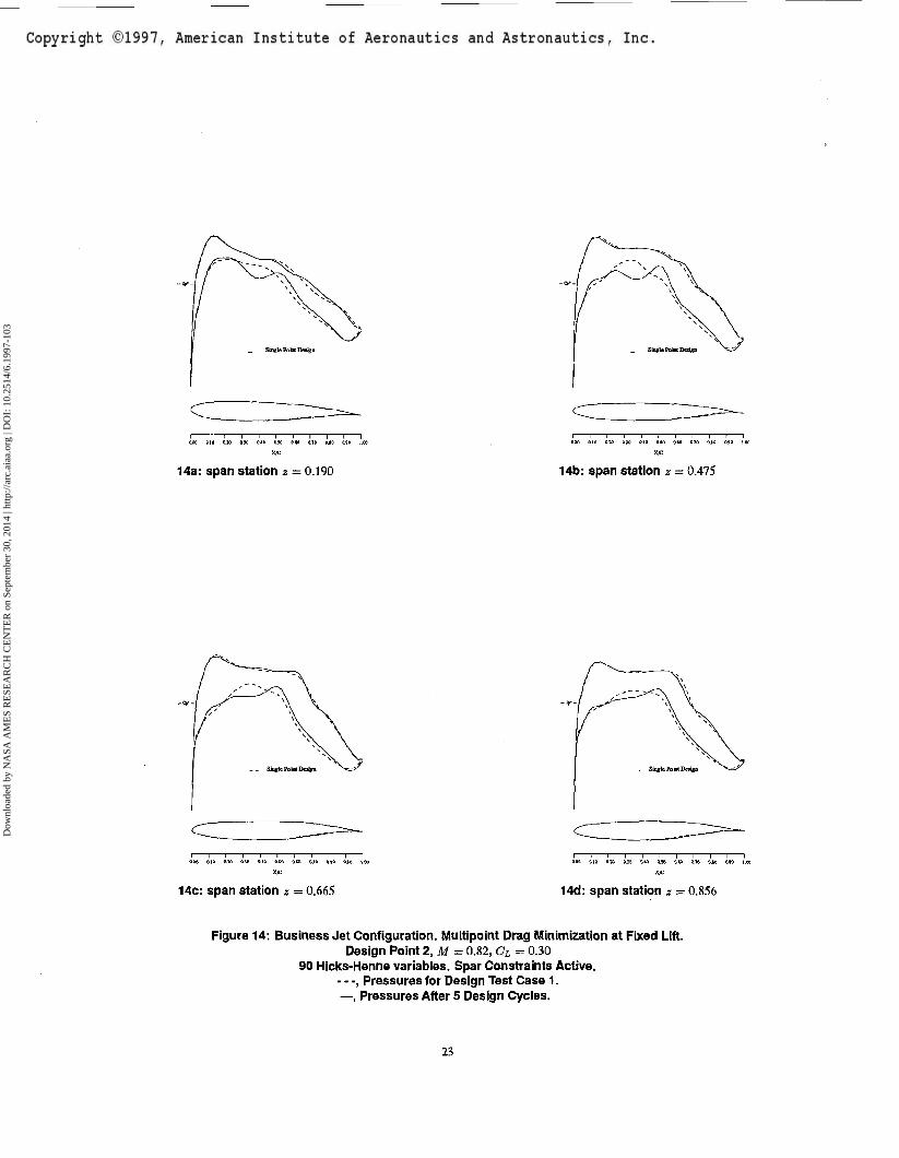
0.81 with a Cx = 0.35, Mach = 0.82 with a CL = 0.30, and Mach =0.83 with a CL = 0.25. Figures (10 - 12) show the initial and finalCp distributions achieved using the same 90 design variables and30 geometric constraints and 5 NPSOL design iterations as for TestCase 1. Note that for each design point the strong shocks present onboth the upper and lower surfaces in the initial configuration havebeen eliminated. Figures (13 - 15) show comparisons of the three-point solution with the single point solution of Test Case 1 at all threedesign points. Interestingly, the upper surface shapes for both finaldesigns are very similar. However, in the case of the single-pointsolution, a strong lower surface shock appears at the Mach = 0.83,CL = 0.25 design point The three-point solution is able to suppressthe formation of this lower surface shock and shows a 9 count dragbenefit over the single-point design at this condition. However, ithas a 1 count penalty at the design condition for which the single-point case was optimized. As in the wing alone multipoint design,a weak single shock is seen for one of the three design points whilea very weak double shock is seen at another design point. Table2 summarizes the drag results for the two design cases. (The CDvalues have been normalized by the drag of the initial configurationat the second design point.) Before proceeding to the next section,
DesignMach0.810.820.83
ConditionsCL
0.350.300.25
InitialCD
1.002571.000001.08731
Test Case 1CD
0.850030.773500.81407
Test Case 2CD
0.854130.779150.76836
Table 2: Drag reduction for single- and multipointdesigns
it should be noted that these business jet design examples are onlyrepresentative of the potential for automated design, and are notintended to provide designs for actual construction. First, in eachcase only 5 NPSOL steps were taken where considerably more couldhave improved the designs slightly. More importantly, for the caseoftransonic designs, the inclusion of viscous effects may prove to havean important impact on the optimized shape. In our future transonicstudies, the Navier-Stokes equations will be employed in place ofthe Euler flow solver used here.
Supersonic Constrained Aircraft DesignIn the case of supersonic design, it is conjectured that as long asturbulent flow is assumed over the entire configuration, the inviscidEuler equations suffice for aerodynamic design since the pressuredrag does not seem to be greatly affected by the inclusion of viscouseffects, and a flat plate skin friction estimate of viscous drag isoften close to the mark. In our current study, the generic supersonictransport configuration used in the design studies of reference [17]is revisited.
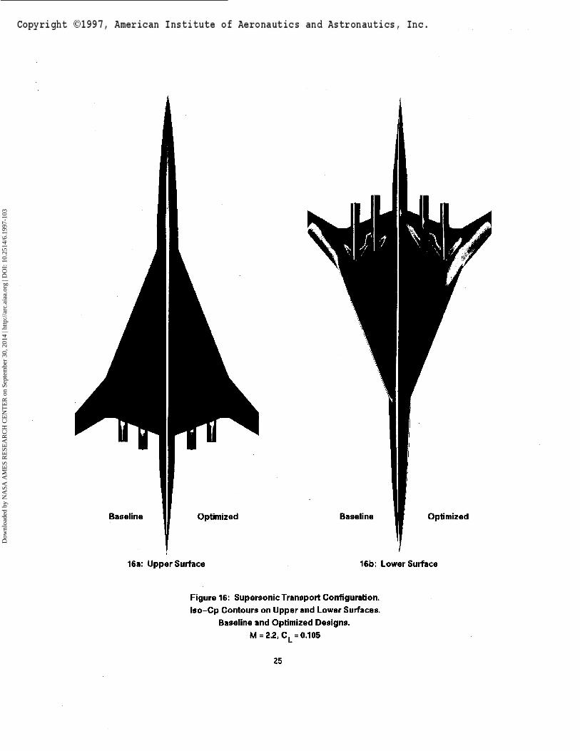
The baseline supersonic transport configuration was sized to ac-commodate 300 passengers with a gross take-off weight of 750,000Ibs. The supersonic cruise point is Mach 2.2 with a CL of 0.105.As can be seen in Figure 16, the planform has a break in the leadingedge sweep. The inboard leading edge sweep is 68.5 degrees whilethe outboard is 49.5 degrees. Since the Mach angle at M = 2.2 is
Dow
nloa
ded
by N
ASA
AM
ES
RE
SEA
RC
H C
EN
TE
R o
n Se
ptem
ber
30, 2
014
| http
://ar
c.ai
aa.o
rg |
DO
I: 1
0.25
14/6
.199
7-10
3
63 degrees it is clear that some leading edge bluntness may be usedinboard without a significant wave drag penalty. Airfoils which useblunt leading edges were created that range from 4% thick at the rootto 2.5% thick at the leading edge break point. The symmetric initialairfoils were chosen with the purpose of accommodating thick sparsat roughly 10% and 80% chord over the span up to the leading edgebreak. Outboard of the leading edge break where the wing sweep isahead of the Mach cone, a sharp leading edge was used to avoid un-due wave drag. The airfoils were chosen to be symmetric, biconvexshapes modified to have a region of constant thickness over the mid-chord. The four-engine configuration features axisymmetric nacellestucked close to the wing lower surface. This layout favors reducedwave drag by minimizing the exposed diverter area. However, itmay be problematic because of the channel flows occurring in thejuncture region of the diverter, wing, and nacelle at the wing trailingedge. The leading edge heights of the diverters are determined bythe boundary layer local displacement thickness such that entrain-ment of boundary layer flow into the engines is avoided. Since thedistances from the wing leading edge to the diverter leading edge aredifferent for the two nacelles, this causes a corresponding diverterheight difference.
The computational mesh on which the design is run has 180 blocksand 1,500K mesh cells, while the underlying geometry entities definethe wing with 16 sectional cuts and the body with 200 sectional cuts.In this case, where we hope to optimize the shape of the wing, caremust be taken to ensure that the nacelles remain properly attachedwith the diverter heights maintained. To accomplish this withoutthe inclusion of additional geometry entities, the portions of thenacelles and diverters that are actually below the wing planformoutline take their associated surface mesh point motion from theirprojected locations on the lower parametric wing surfaces.
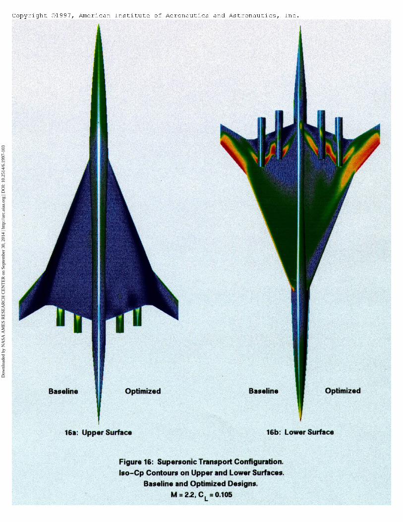
The objective of the design is to reduce the drag at the single designpoint (Mach = 2.2, CL = 0.105) by modifying the wing shape. Justas in the transonic cases, 18 design variables of the Hicks-Hennetype are chosen for a given wing defining section. However, insteadof applying them to all 16 sections, they are applied to 8 of thesections and then lofted linearly to the neighboring sections. Sparconstraints are imposed for all wing defining sections at x/c = 0.05and x/c = 0.8. An additional maximum thickness constraint isspecified along the span at x/c = 0.5. A final thickness constraint isenforced ati/c = 0.95 to ensure a reasonable trailing edge includedangle. An iso-Cp representation of the initial and final designs isdepicted in Figure 16 for both the upper and lower surfaces.
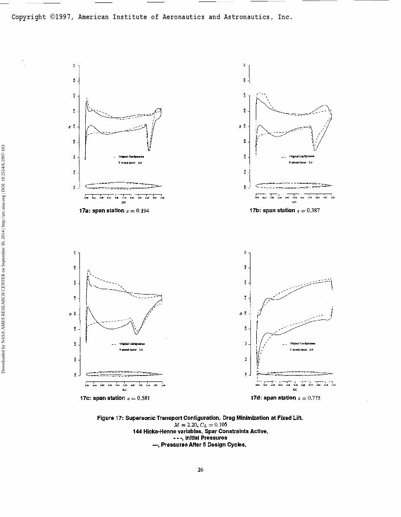
It is noted that the strong oblique shock evident near the leadingedge of the upper surface on the initial configuration is largely elim-inated in the final design after 5 NPSOL design iterations. It is alsoseen that the upper surface pressure distribution in the vicinity of thenacelles has formed an unexpected pattern. However, it is recalledthat thickness constraints abound in this design, and these upper sur-face pressure patterns are conjectured to be the result of sculpting ofthe lower surface near the nacelles which affects the upper surfaceshape through the thickness constraints. For the lower surface, theleading edge has developed a suction region while the shocks andexpansions around the nacelles have been somewhat reduced. Fig-ure 17 shows the pressure coefficients and (scaled) airfoil sectionsfor four sectional cuts along the wing. These further demonstratethe removal of the oblique shock on the upper surface, and the ad-dition of a suction region on the leading edge of the lower surface.
The airfoil sections have been scaled by a factor of 2 so that shapechanges may be seen more easily. Most notably, the section at 38.7%span has had the lower surface drastically modified such that a largeregion of the aft airfoil has a forward-facing portion near where thepressure spike from the nacelle shock impinges on the surface. Thefinal overall pressure drag was reduced by 8%, from CD - 0.0088to CD = 0.0081.
CONCLUSIONS
In the period since this approach to optimal shape design was firstproposed by the second author [8], the method has been verified bynumerical implementation for both potential flow and flows mod-eled by the Euler equations [9, 19, 15, 11]. In two accompanyingpapers at this conference, the method is being extended to treat theNavier-Stokes equations [12,14]. It has been demonstrated that themethod can be used successfully with a finite volume formulationto perform calculations with arbitrary numerically generated grids[19,15]. Further, results have been presented for three-dimensionalcalculations using both the analytic mapping and general finite vol-ume implementations [20]. In the last year the technique has beenadopted by some industry participants to perform the aerodynamicdesign of future configurations [ 1 ]. With the parallel implementationof the multiblock design algorithm now complete, the technology hasadvanced to the degree that aerodynamic shape design of completeaircraft configurations with very rapid turnaround is possible.
In this paper we have shown how the complicated design ofboth transonic and supersonic aircraft configurations including air-frame/nacelle integration effects can be accomplished in a routinefashion for multiple design points and with the inclusion of con-straints. While the results presented in this paper have been re-stricted to the inviscid Euler equations, this limitation will soonbe overcome in our future work. The focus here was instead todemonstrate the feasibility of realistic designs governed by simplegeometry entities that are assembled and treated during the designprocess. Furthermore, with the proven coupling to NPSOL and theaddition of multiple design point capability, the door is truly openfor the method to act as a crucial element of a high fidelity MDOtechnique capable of revolutionizing aircraft design.
All analysis and design cases were performed on parallel archi-tecture machines in less than one day, demonstrating that completeconfiguration designs may be achieved with rapid turn-around evenwith the most conservative estimates of available computational re-sources. In future efforts, additional disciplines will be coupled intothe techniques presented here while work continues on the unstruc-tured grid approaches and on the inclusion of viscous effects.
ACKNOWLEDGMENTS
This research has benefited greatly from the generous support of theAFOSR under grant number AFOSR-91-0391, ARPA under grantnumber N00014-92-J-1976, USRA through RIACS, the High SpeedResearch branch of NASA Ames Research Center, and IBM.
References
[1] J. Gallman, J. Reuther, N. Pfeiffer, W. Forrest, and D. Bemstorf.Business jet wing design using aerodynamic shape optimiza-
Dow
nloa
ded
by N
ASA
AM
ES
RE
SEA
RC
H C
EN
TE
R o
n Se
ptem
ber
30, 2
014
| http
://ar
c.ai
aa.o
rg |
DO
I: 1
0.25
14/6
.199
7-10
3
tion. AIAA paper 96-0554,34th Aerospace Sciences Meetingand Exhibit, Reno, Nevada, January 1996.
[2] P.E. GUI, W. Murray, M.A. Saunders, and M.A. Wright. User'sguide for NPSOL (version 4.0). a FORTRAN package nonlin-ear programming. Technical Report SOL86-2, Stanford Uni-versity, Department of Operations Research, 1986.
[3] P.E. Gill, W. Murray, and M.H. Wright. PracticalOptimization.Academic Press, 1981.
[4] R. M. Hicks and P. A. Henne. Wing design by numericaloptimization. Journal of Aircraft, 15:407-412,1978.
[5] R. M. Hicks, E. M. Murman, and G. N. Vanderplaats. Anassessment of airfoil design by numerical optimization. NASATMX-3092, Ames Research Center, Moffett Field, California,July 1974.
[6] A. Jameson. Solution of the Euler equations for two dimen-sional transonic flow by a multigrid method. Applied Mathe-matics and Computations, 13:327-356,1983.
[7] A. Jameson. Multigrid algorithms for compressible flow calcu-lations. In W. Hackbusch and U. Trottenberg, editors, LectorsNotes in Mathematics, Vol. 1228, pages 166-201. Proceed-ings of the 2nd European Conference on Multigrid Methods,Cologne, 1985, Springer-Verlag, 1986.
[8] A. Jameson. Aerodynamic design via control theory. Journalof Scientific Computing, 3:233-260,1988.
[9] A. Jameson. Automatic design of transonic airfoils to reducethe shock induced pressure drag. In Proceedings of the 31stIsrael Annual Conference on Aviation and Aeronautics, TelAviv, pages 5-17, February 1990.
[10] A. Jameson. Optimum aerodynamic design via boundary con-trol. In AGARD-VKILecture Series, Optimum DesignMethodsin Aerodynamics, von Karman Institute for Fluid Dynamics,1994.
[11] A. Jameson. Optimum Aerodynamic Design Using ControlTheory, Computational Fluid Dynamics Review 1995. Wiley,1995.
[12] A. Jameson. Re-engineering the design process through com-putation. AIAA paper 97-0641,35th Aerospace Sciences Meet-ing and Exhibit, Reno, Nevada, January 1997.
[13] A. Jameson and J.J. Alonso. Automatic aerodynamic optimiza-tion ondistributed memory architectures. AIAA paper 96-0409,34th Aerospace Sciences Meeting and Exhibit, Reno, Nevada,January 1996.
[14] A. Jameson, L. Martinelli, and N. Pierce. Optimum aero-dynamic design using the navier-stokes equations. AIAA pa-per 97-0101, 35th Aerospace Sciences Meeting and Exhibit,Reno, Nevada, January 1997.
[15] A. Jameson and J. Reuther. Control theory based airfoil de-sign using the Euler equations. AIAA paper 94-4272, 5thAIAA/USAF/NAS A/ISSMO Symposium on MultidisciplinaryAnalysis and Optimization, Panama City Beach, FL, Septem-ber 1994.
[16] A. Jameson, W. Schmidt, and E. Turkel. Numerical solutionsof the Euler equations by finite volume methods with Runge-Kutta time stepping schemes. AIAA paper 81-1259, January1981.
[17] J. Reuther, J.J. Alonso, MJ. Rimlinger, and A. Jameson.Aerodynamic shape optimization of supersonic aircraft con-figurations via an adjoint formulation on parallel computers.AIAA paper 96-4045, 6th AIAA/NASA/ISSMO Symposiumon Multidisciplinary Analysis and Optimization, Bellevue,WA, September 1996.
[18] J. Reuther, S. Cliff, R. Hicks, and C.P. van Dam. Practical de-sign optimization of wing/body configurations using the Eulerequations. AIAA paper 92-2633,1992.
[19] J. Reuther and A. Jameson. Control theory based airfoil designfor potential flow and a finite volume discretization. AIAApaper 94-0499,32nd Aerospace Sciences Meeting and Exhibit,Reno, Nevada, January 1994.
[20] J. Reuther and A. Jameson. Aerodynamic shape optimizationof wing and wing-body configurations using control theory.AIAA paper 95-0123, 33rd Aerospace Sciences Meeting andExhibit, Reno, Nevada, January 1995.
[21] J. Reuther and A. Jameson. A comparison of design variablesfor control theory based airfoil optimization. Technical report,6th International Symposium on Computational Fluid Dynam-ics, Lake Tahoe, Nevada, September 1995.
[22] J. Reuther and A. Jameson. Supersonic wing and wing-bodyshape optimization using an adjoint formulation. Technical re-port, The Forum on CFD for Design and Optimization, (IMECE95), San Francisco, California, November 1995.
[23] J. Reuther, A. Jameson, J. Farmer, L. Martinelli, and D. Saun-ders. Aerodynamic shape optimization of complex aircraft con-figurations via an adjoint formulation. AIAA paper 96-0094,34th Aerospace Sciences Meeting and Exhibit, Reno, Nevada,January 1996.
[24] J. Reuther, C.P. van Dam, and R. Hicks. Subsonic and transoniclow-Reynolds-number airfoils with reduced pitching moments.Journal of Aircraft, 29:297-298,1992.
[25] J. J. Reuther. Aerodynamic shape optimization using controltheory. Ph. D. Dissertation, University of California, Davis,Davis, CA, June 1996.
[26] J.P. Steinbrenner, J.R. Chawner, and C.L. Pouts. The GRID-GEN 3D multiple block grid generation system. Technicalreport, Flight Dynamics Laboratory, Wright Research and De-velopment Center, Wright-Patterson Air Force Base, Ohio, July1990.
[27] J.F. Thompson, Z.U.A Warsi, and C.W. Mastin. NumericalGrid Generation, Foundations and Applications. Elsevier Sci-ence Publishing Company, New York, NY, 1985.
10
Dow
nloa
ded
by N
ASA
AM
ES
RE
SEA
RC
H C
EN
TE
R o
n Se
ptem
ber
30, 2
014
| http
://ar
c.ai
aa.o
rg |
DO
I: 1
0.25
14/6
.199
7-10
3
1a: Initial Wing 1b: 60 Design Iterations
Figure 1: Lifting Design Case, M = 0.85, Fixed Lift Mode.Multipoint Drag Reduction, Initial and Final Wings.
11
Dow
nloa
ded
by N
ASA
AM
ES
RE
SEA
RC
H C
EN
TE
R o
n Se
ptem
ber
30, 2
014
| http
://ar
c.ai
aa.o
rg |
DO
I: 1
0.25
14/6
.199
7-10
3

UPPER SURFACE PRESSURE UPPER SURFACE PRESSURE
2a: Initial WingCL = 0.4995, CD = 0.0156, a = -1.471°
2b: 60 Design IterationsCL = 0.5000, CD = 0.0114, a = -0.933°
Figure 2: Multipoint Lifting Design Case: First Design Point, M = 0.85, CL = 0.5000Fixed Lift Mode, Drag Reduction.
12
Dow
nloa
ded
by N
ASA
AM
ES
RE
SEA
RC
H C
EN
TE
R o
n Se
ptem
ber
30, 2
014
| http
://ar
c.ai
aa.o
rg |
DO
I: 1
0.25
14/6
.199
7-10
3
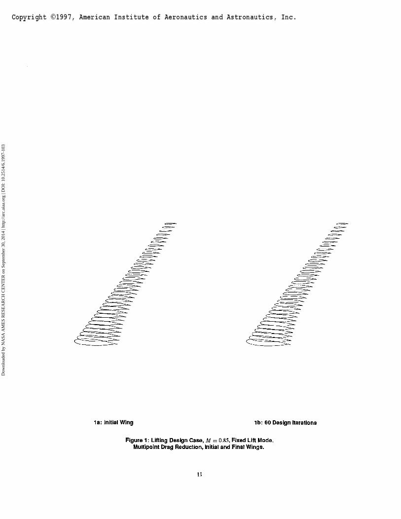
UPPER SURFACE PRESSURE UPPER SURFACE PRESSURE
3a: Initial WingCL = 0.5243, CD = 0.0173, a = -1.300°
3b: 60 Design IterationsCL = 0.5251, CD = 0.0123, a = -0.770°
Figure 3: Muttipoint Lining Design Case: Second Design Point, M = 0.85, CL = 0.5250Fixed Lift Mode, Drag Reduction.
13
Dow
nloa
ded
by N
ASA
AM
ES
RE
SEA
RC
H C
EN
TE
R o
n Se
ptem
ber
30, 2
014
| http
://ar
c.ai
aa.o
rg |
DO
I: 1
0.25
14/6
.199
7-10
3

UPPER SURFACE PRESSURE UPPER SURFACE PRESSURE
4a: Initial WingCL = 0.5490, CD = 0.0191, a = -1.128°
4b: 60 Design IterationsCL = 0.5501, CD = 0.0135, a = -0.608°
Figure 4: Multipoint Lifting Design Case: Third Design Point, M = 0.85, CL - 0.5500Fixed Lift Mode, Drag Reduction.
14
Dow
nloa
ded
by N
ASA
AM
ES
RE
SEA
RC
H C
EN
TE
R o
n Se
ptem
ber
30, 2
014
| http
://ar
c.ai
aa.o
rg |
DO
I: 1
0.25
14/6
.199
7-10
3
& 1-
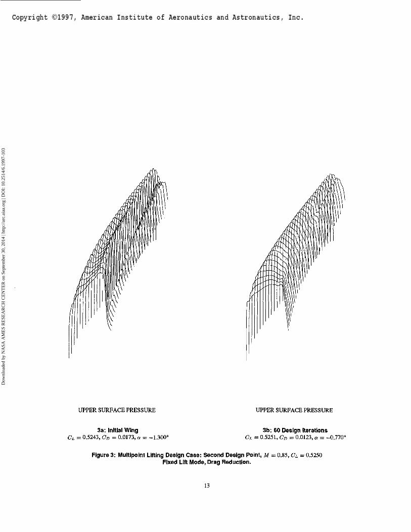
5a: Initial Wing, Span Station z = 0.484 5b: Design After 60 Cycles, Span Station z = 0.484
Figure 5: Multipoint Lifting Design Case, Design Point 1:Fixed Lift Drag Minimization.
M = 0.85, CL = 0.500, Pressure Coefficients of Initial and Final Wing Sections.
15
Dow
nloa
ded
by N
ASA
AM
ES
RE
SEA
RC
H C
EN
TE
R o
n Se
ptem
ber
30, 2
014
| http
://ar
c.ai
aa.o
rg |
DO
I: 1
0.25
14/6
.199
7-10
3

6a: Initial Wing, Span Station z = 0.484 6b: Design After 60 Cycles, Span Station 2 = 0.484
FigureG: Multipoint Lifting Design Case, Design Point 2:Fixed Lift Drag Minimization.
M = 0.85, CL = 0.525, Pressure Coefficients of Initial and Final Wing Sections.
/
^—————
7a: Initial Wing, Span Station z - 0.484 7b: Design After 60 Cycles, Span Station z = 0.484
Figure?: Multipoint Lifting Design Case, Design Point3:Fixed Lift Drag Minimization.
M = 0.85, CL = 0.550, Pressure Coefficients of Initial and Final Wing Sections.
16
Dow
nloa
ded
by N
ASA
AM
ES
RE
SEA
RC
H C
EN
TE
R o
n Se
ptem
ber
30, 2
014
| http
://ar
c.ai
aa.o
rg |
DO
I: 1
0.25
14/6
.199
7-10
3
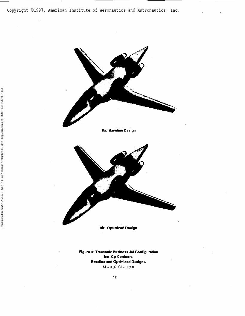
8a: Baseline Design
8b: Optimized Design
Figure 8: Transonic Business Jet ConfigurationIso-Cp Contours.
Baseline and Optimized Designs.M = 0.82, Cl = 0.550
17
Dow
nloa
ded
by N
ASA
AM
ES
RE
SEA
RC
H C
EN
TE
R o
n Se
ptem
ber
30, 2
014
| http
://ar
c.ai
aa.o
rg |
DO
I: 1
0.25
14/6
.199
7-10
3
9a: span station z = 0.190 9b: span station z = 0.475
9c: span station z = 0.665
d
0.00 0.10 0.10 O.M 0.40 OJO 0*0 070 010 040
9d: span station z = 0.856
Figures: Business Jet Configuration Configuration. Drag Minimization at Fixed Lift.M = 0.82, CL = 0.3
90 Hicks-Henne variables. Spar Constraints Active.- - -, Initial Pressures
—, Pressures After 5 Design Cycles.
18
Dow
nloa
ded
by N
ASA
AM
ES
RE
SEA
RC
H C
EN
TE
R o
n Se
ptem
ber
30, 2
014
| http
://ar
c.ai
aa.o
rg |
DO
I: 1
0.25
14/6
.199
7-10
3
0.00 aio a» aeo OTO 010 o»o
10a: span station z = 0.190
_ . Ongjnil ConfiguIMico
10b: span station z - 0.475
10c: span station z = 0.665
000 OIO 0.20 O.JO (HO 030 0.60 010 OJO 0.90 1.00
10d: span station z = 0.856
Figure 10: Business Jet Configuration. Multipoint Drag Minimization at Fixed Lift.Design Point \,M= 0.81, CL - 0.35
90 Hicks-Henne variables. Spar Constraints Active.- - -, Initial Pressures
—, Pressures After 5 Design Cycles.
19
Dow
nloa
ded
by N
ASA
AM
ES
RE
SEA
RC
H C
EN
TE
R o
n Se
ptem
ber
30, 2
014
| http
://ar
c.ai
aa.o
rg |
DO
I: 1
0.25
14/6
.199
7-10
3
1——I——I——I——I——I——I——I——I——I——[000 0.10 0.10 030 040 0.10 Q«0 0.70 010 040 1.00
11a: span station a = 0.190
0.10 OJO O.<0
11b: span station z = 0.475
0.00 0,10 010 0.10 040 QM> OW 0.70 OJO 0.90 100 ooo 010 aw a» a>o oio ato 0.70 DID a«o i.w
11c: span station z = 0.665 11d: span station z = 0.856
Figure 11: Business Jet Configuration. Multipoint Drag Minimization at Fixed Lift.Design Point 2, M = 0.82, CL = 0.30
90 Hicks-Henne variables. Spar Constraints Active.- - -, Initial Pressures
—, Pressures After 5 Design Cycles.
20
Dow
nloa
ded
by N
ASA
AM
ES
RE
SEA
RC
H C
EN
TE
R o
n Se
ptem
ber
30, 2
014
| http
://ar
c.ai
aa.o
rg |
DO
I: 1
0.25
14/6
.199
7-10
3
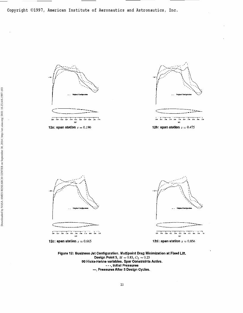
12a: span station * = 0.190
0.30 0.30 0.40 D.JO 0 60 0.70 O.(0 O.W
12b: span station z = 0.475
12c: span station z = 0.665
000 0.10 tt» 0.30 0.40 O.JO 0.60 0.70
12d: span station z = 0.856
Figure 12: Business Jet Configuration. Multipoint Drag Minimization at Fixed Lift.Design Point 3, M = 0.83, CL = 0.25
90 Hicks-Henne variables. Spar Constraints Active.- - -, Initial Pressures
—, Pressures After 5 Design Cycles.
21
Dow
nloa
ded
by N
ASA
AM
ES
RE
SEA
RC
H C
EN
TE
R o
n Se
ptem
ber
30, 2
014
| http
://ar
c.ai
aa.o
rg |
DO
I: 1
0.25
14/6
.199
7-10
3
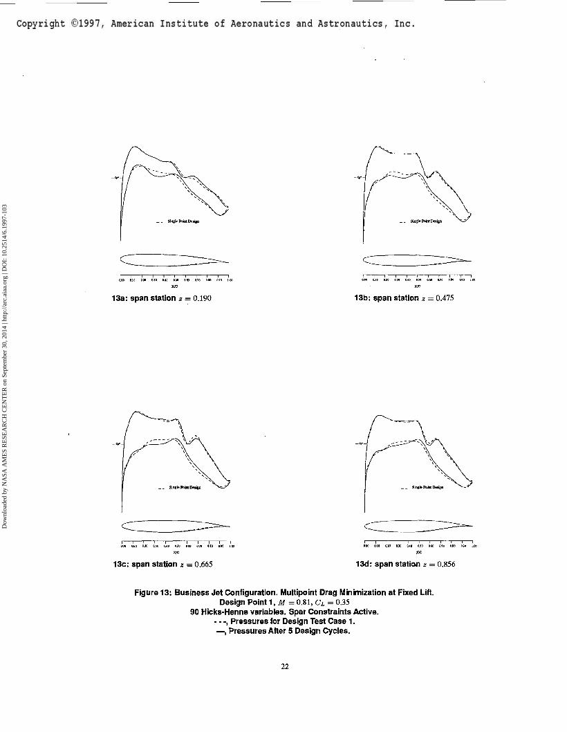
13a: span station z = 0.190
d
13b: span station z = 0.475
d
13c: span station z = 0.665
d
13d: span station z - 0.856
Figure 13: Business Jet Configuration. Multipoint Drag Minimization at Fixed Lift.Design Point 1, M = 0.81, CL = 0.35
90 Hicks-Henne variables. Spar Constraints Active.- - -, Pressures for Design Test Case 1.—, Pressures After 5 Design Cycles.
22
Dow
nloa
ded
by N
ASA
AM
ES
RE
SEA
RC
H C
EN
TE
R o
n Se
ptem
ber
30, 2
014
| http
://ar
c.ai
aa.o
rg |
DO
I: 1
0.25
14/6
.199
7-10
3
o.?o o.io tat i.oo
14a: span station z = 0.190 14b: span station z = 0.475
14c: span station z - 0.665
0.10 O.JO 0.30 0.49 130 0.40 0.70 0.10 <WO I.CC
14d: span station z = 0.856
Figure 14: Business Jet Configuration. Multipoint Drag Minimization at Fixed Lift.Design Point 2, M = 0.82, CL = 0.30
90 Hicks-Henne variables. Spar Constraints Active.- - -, Pressures for Design Test Case 1.—, Pressures After 5 Design Cycles.
23
Dow
nloa
ded
by N
ASA
AM
ES
RE
SEA
RC
H C
EN
TE
R o
n Se
ptem
ber
30, 2
014
| http
://ar
c.ai
aa.o
rg |
DO
I: 1
0.25
14/6
.199
7-10
3
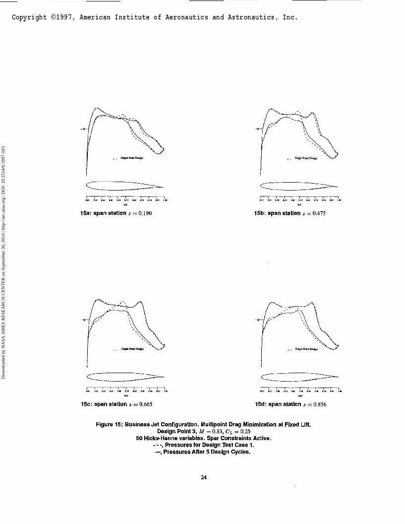
15a: span station z — 0.190 15b: span station z = 0.475
~~\———1———!———I"
15c: span station z = 0.665
0.00 0.19 0.30 0,30 0,40
15d: span station z = 0.856
Figure 15: Business Jet Configuration. Multipoint Drag Minimization at Fixed Lift.Design Point 3, M = 0.83, CL = 0.25
90 Hicks-Henne variables. Spar Constraints Active.- - -, Pressures for Design Test Case 1.—, Pressures After 5 Design Cycles.
24
Dow
nloa
ded
by N
ASA
AM
ES
RE
SEA
RC
H C
EN
TE
R o
n Se
ptem
ber
30, 2
014
| http
://ar
c.ai
aa.o
rg |
DO
I: 1
0.25
14/6
.199
7-10
3
Baseline Optimized Baseline Optimized
16a: Upper Surface 16b: Lower Surface
Figure 16: Supersonic Transport Configuration.Iso-Cp Contours on Upper and Lower Surfaces.
Baseline and Optimized Designs.M = 22, CL = 0.105
25
Dow
nloa
ded
by N
ASA
AM
ES
RE
SEA
RC
H C
EN
TE
R o
n Se
ptem
ber
30, 2
014
| http
://ar
c.ai
aa.o
rg |
DO
I: 1
0.25
14/6
.199
7-10
3
_ _ Origin*] OaGgunlktt
Y we** fitfa; 2.0
000 Old O.M B.30 0.40 ftiS 0,M 9,79 410 0.10
17a: span station z = 0.194
a CI
17b: span station z = 0.387
5 -I
17c: span station z = 0.581 17d: span station « = 0.775
Figure 17: Supersonic Transport Configuration. Drag Minimization at Fixed Lift.M = 2.20, CL =0.105
144 Hicks-Henne variables. Spar Constraints Active.- - -, Initial Pressures
—, Pressures After 5 Design Cycles.
26
Dow
nloa
ded
by N
ASA
AM
ES
RE
SEA
RC
H C
EN
TE
R o
n Se
ptem
ber
30, 2
014
| http
://ar
c.ai
aa.o
rg |
DO
I: 1
0.25
14/6
.199
7-10
3
Copyright ©1997, American Institute of Aeronautics and Astronautics, Inc.
Dow
nloa
ded
by N
ASA
AM
ES
RE
SEA
RC
H C
EN
TE
R o
n Se
ptem
ber
30, 2
014
| http
://ar
c.ai
aa.o
rg |
DO
I: 1
0.25
14/6
.199
7-10
3
Copyright ©1997, American Institute of Aeronautics and Astronautics, Inc.
Dow
nloa
ded
by N
ASA
AM
ES
RE
SEA
RC
H C
EN
TE
R o
n Se
ptem
ber
30, 2
014
| http
://ar
c.ai
aa.o
rg |
DO
I: 1
0.25
14/6
.199
7-10
3
Related Documents