Electrical, Control and Communication Engineering 71 ISSN 2255-9159 (online) ISSN 2255-9140 (print) 2018, vol. 14, no. 1, pp. 71–80 doi: 10.2478/ecce-2018-0008 https://www.degruyter.com/view/j/ecce ©2018 Ilya Galkin et al. This is an open access article licensed under the Creative Commons Attribution License (http://creativecommons.org/licenses/by/4.0), in the manner agreed with Sciendo. Considerations Regarding the Concept of Cost-Effective Power-Assist Wheelchair Subsystems (Case Study and Initial Evaluation) Ilya Galkin * (Professor, Riga Technical University, Riga, Latvia), Andrejs Podgornovs (Researcher, Riga Technical University, Riga, Latvia), Andrei Blinov (Researcher, Tallinn University of Technology, Tallinn, Estonia), Kristaps Vitols (Doctoral student, Riga Technical University, Riga, Latvia), Maxim Vorobyov (Doctoral student, Riga Technical University, Riga, Latvia), Roman Kosenko (Doctoral student, Tallinn University of Technology, Tallinn, Estonia) * Corresponding author. E-mail: [email protected] Abstract – The present paper deals with the concept of a cost- effective power-assistant wheelchair. An analysis of the market situation and recent technical achievements is done at the beginning. On its basis, a set of solutions suitable for the development of such wheelchairs has been composed. It is shown that the key features of the considered concept are: segmented electrical motor and drive, sectioned battery pack, modular charger and an ANN matrix that provides easy and intuitive interfacing of sensor networks, pseudo-bionic feedbacks and the decision-making unit. Within the scope of the paper, a 3D model has been developed and 3D modelling has been conducted. As a result, certain drawbacks in the design and placement of elements have been found and a modification of the concept has been proposed. Keywords – Artificial neural networks; Batteries; Electrical drives; Human-machine interface; Medical control systems. I. INTRODUCTION Wheelchairs are typically considered as very specific products dedicated for quite a narrow group of users. At the same time, the World Health Organization (WHO) reports that one third of a billion of elderly and disabled persons have mobility problems [1]. Many of these persons are highly motivated to improve their mobility by combining the electrical powering of their wheelchairs with muscle- powering, thus ensuring their own maximum possible participation in daily life (i.e. assuming the use of assisting wheelchairs). They really expect technical tools to achieve this goal. At the same time, wheelchairs have been historically developed for persons with disabilities caused by an illness or an injury, which are different compared with disabilities related to ageing. While senior citizens require powered wheelchairs with quite a typical and predictable level of assistance, the wheelchairs for persons with disability acquired due to an injury or illnesses often require a more specific design – it could be a simpler or a more complex one, but always centred on the human-machine interface. This allows concluding that the level of assisting power and, therefore, the size and weight of electrical drives of the considered wheelchairs, as well as the size and weight of their battery packs, are very different. This consideration also regards the human-machine interface of the wheelchairs, which is very different for different occasions. This makes the development of each particular wheelchair unique and individual, which in turn impacts the cost and availability of the wheelchairs. In this report, a set of electrical, material and control technologies are considered with the final goal to overcome this difficulty. II. PERSONS WITH DISABILITIES Persons with disabilities are either people with impairments, activity limitations or people with participation restrictions. Basically, the causes of disability are: for countries with high incomes, chronic diseases like diabetes, obesity that eventually leads to severe consequences (limb amputation, heart attacks, stroke); for countries with low income per capita, disability is caused by infectious diseases; injuries and injuries do not depend depend on the income of the population but rather on the circumstances [1, p. 34]. Another important aspect is the age of the patients – the older the patient, the greater the probability of disability. In low-income countries, the number of people with disabilities is higher [1, p. 35]. The data on children with disabilities are contradictory. Different sources use different methods for statistical analysis (mainly surveys that are universal for adults). Approximately 93 million children from 0 to 14 years of age suffer from an average disability, while for other calculations, only 1.5 million [1, The preparing of this publication is supported by the European Regional Development Fund (ERDF) within the contract No. 1.1.1.1/16/A/147 “Research and Development of Electrical, Information and Material Technologies for Low Speed Rehabilitation Vehicles for Disabled People”.

Welcome message from author
This document is posted to help you gain knowledge. Please leave a comment to let me know what you think about it! Share it to your friends and learn new things together.
Transcript
Electrical, Control and Communication Engineering
71
ISSN 2255-9159 (online) ISSN 2255-9140 (print) 2018, vol. 14, no. 1, pp. 71–80 doi: 10.2478/ecce-2018-0008 https://www.degruyter.com/view/j/ecce
©2018 Ilya Galkin et al. This is an open access article licensed under the Creative Commons Attribution License (http://creativecommons.org/licenses/by/4.0), in the manner agreed with Sciendo.
Considerations Regarding the Concept of Cost-Effective Power-Assist Wheelchair Subsystems
(Case Study and Initial Evaluation)
Ilya Galkin* (Professor, Riga Technical University, Riga, Latvia), Andrejs Podgornovs (Researcher, Riga Technical University, Riga, Latvia),
Andrei Blinov (Researcher, Tallinn University of Technology, Tallinn, Estonia), Kristaps Vitols (Doctoral student, Riga Technical University, Riga, Latvia),
Maxim Vorobyov (Doctoral student, Riga Technical University, Riga, Latvia), Roman Kosenko (Doctoral student, Tallinn University of Technology, Tallinn, Estonia)
* Corresponding author. E-mail: [email protected]
Abstract – The present paper deals with the concept of a cost-effective power-assistant wheelchair. An analysis of the market situation and recent technical achievements is done at the beginning. On its basis, a set of solutions suitable for the development of such wheelchairs has been composed. It is shown that the key features of the considered concept are: segmented electrical motor and drive, sectioned battery pack, modular charger and an ANN matrix that provides easy and intuitive interfacing of sensor networks, pseudo-bionic feedbacks and the decision-making unit. Within the scope of the paper, a 3D model has been developed and 3D modelling has been conducted. As a result, certain drawbacks in the design and placement of elements have been found and a modification of the concept has been proposed.
Keywords – Artificial neural networks; Batteries; Electrical
drives; Human-machine interface; Medical control systems.
I. INTRODUCTION
Wheelchairs are typically considered as very specific products dedicated for quite a narrow group of users. At the same time, the World Health Organization (WHO) reports that one third of a billion of elderly and disabled persons have mobility problems [1]. Many of these persons are highly motivated to improve their mobility by combining the electrical powering of their wheelchairs with muscle-powering, thus ensuring their own maximum possible participation in daily life (i.e. assuming the use of assisting wheelchairs). They really expect technical tools to achieve this goal. At the same time, wheelchairs have been historically
developed for persons with disabilities caused by an illness or an injury, which are different compared with disabilities related to ageing. While senior citizens require powered wheelchairs with quite a typical and predictable level of assistance, the wheelchairs for persons with disability acquired due to an injury or illnesses often require a more specific design – it could be a simpler or a more complex one, but always centred on the human-machine interface.
This allows concluding that the level of assisting power and, therefore, the size and weight of electrical drives of the considered wheelchairs, as well as the size and weight of their battery packs, are very different. This consideration also regards the human-machine interface of the wheelchairs, which is very different for different occasions. This makes the development of each particular wheelchair unique and individual, which in turn impacts the cost and availability of the wheelchairs. In this report, a set of electrical, material and control technologies are considered with the final goal to overcome this difficulty.
II. PERSONS WITH DISABILITIES
Persons with disabilities are either people with impairments, activity limitations or people with participation restrictions. Basically, the causes of disability are: for countries with high incomes, chronic diseases like diabetes, obesity that eventually leads to severe consequences (limb amputation, heart attacks, stroke); for countries with low income per capita, disability is caused by infectious diseases; injuries and injuries do not depend depend on the income of the population but rather on the circumstances [1, p. 34]. Another important aspect is the age of the patients – the older the patient, the greater the probability of disability. In low-income countries, the number of people with disabilities is higher [1, p. 35]. The data on children with disabilities are contradictory. Different sources use different methods for statistical analysis (mainly surveys that are universal for adults). Approximately 93 million children from 0 to 14 years of age suffer from an average disability, while for other calculations, only 1.5 million [1,
The preparing of this publication is supported by the European Regional Development Fund (ERDF) within the contract No. 1.1.1.1/16/A/147 “Research and Development of Electrical, Information and Material Technologies for Low Speed Rehabilitation Vehicles for Disabled People”.
Electrical, Control and Communication Engineering
________________________________________________________________________________________2018, vol. 14, no. 1
72
p. 36]. In developed countries, people with disabilities are able to earn as much as their peers, the earnings depend on the level of education, and thus they are less vulnerable to poverty than those from developing countries, who, due to social aspects, cannot receive a full-fledged education. The monthly costs incurred by disabled people are higher than those of their healthy peers in the United Kingdom, ranging from 11 % to 69 %, depending on the nature of the disorder, the help of relatives, the state, and so on. There are around 785 (15.6 % according to the World Health Survey) to 975 (19.4 % according to the Global Burden of Disease Study) million persons 15 years and older living with a disability, based on the 2010 population estimates (6.9 billion with 1.86 billion under 15 years). Out of these, the World Health Survey estimates that 110 million people (2.2 %) have very significant difficulties in functioning while the Global Burden of Disease Study estimates that 190 million (3.8 %) have a “severe disability” – the equivalent of disability inferred for conditions such as quadriplegia, severe depression, or blindness. Including children, over a billion people (15 % of the world’s population) were estimated to be living with disability.
According to 2016 data for the United States of America, the number of disabled persons within the last 8 years has been about 12% of the total population. The distribution of these persons across different age groups is not even: in the group of 0–5-year-old children only 0.4% are disabled, in the group of 6–17-year-old people — already 7.3%, in the group aged 18–64 — 51% and in the group of people older than 65, more than 41% are disabled. About 12% of people with disabilities are people with impairments. These mainly belong to the older generation. The poverty level of disabled people is by 7% higher than the average [2].
Eurostat data for 2015 [3] show that 14% of the people aged 15–64 have a disability. 7.6% of them suffered from impaired movement. The risk of poverty of the people with disabilities in Europe is between 12 and 24%.
The above-considered data show that even in developed countries the question of the cost of the equipment for disabled persons is significant. On the other hand, the production expenses of such equipment depend on its functionality, which in turn depends on the disability level of a particular person. Even a tentative analysis shows that the disabled people with restriction of movement belong to one of three groups [4]: (1) wheelchair users who can partially move one of the extremities, including paraplegics; (2) persons with paraplegia or quadriplegia, who at least partially can move, but for a limited time; (3) persons who cannot move at all (typically due to quadriplegia or other reasons). The functional requirements of these groups are very different and the cost of the corresponding equipment varies over a very wide range.
III. EXISTING WHEELCHAIR TECHNOLOGIES
A. General Considerations
The powered wheelchairs available on the market can be divided into fully powered, powered with assisted drive and “smart” wheelchairs. Manual wheelchairs powered with the muscle power of the patient are not considered further in this
article. Fully powered wheelchairs are usually controlled manually directly by a human with different kind of interfaces like joystick, chin control, tongue control, head movement and similar. Joysticks can be equipped with kinaesthetic feedback [5] and specific control strategies [6] — such wheelchairs are mainly used by the first kind of users. Power-assisted wheelchairs are partially powered electrically. Their control is usually similar to that of non-powered wheelchairs except specific drive algorithms. Smart wheelchairs are complete mobile robots, which receive complex commands from the user and have the so-called protection skirt (an infrared or ultrasonic sensor network around the wheelchair) [7]. These wheelchairs can evaluate their operation environment and define speed, direction etc. and are usually used by the second and third group of patients. Again, the cost of the equipment intended for people with a similar disability varies over a very wide range. The smart wheelchairs are practically available to only a few individuals from the last group of users.
B. Existing Control Interfaces
Various interfaces have been developed for individuals with severe impairments: the so-called “sip-and-puff system” [4], the voice recognition system [5], the speech frequency recognition system [4], the eye tracking system [8] as well as the use of electromagnetic signals of muscles or electromyography (EMG) [9]. The advantage of this latter method is the substitution of the joystick with EMG sensors and absence of hand controls. The disadvantage is that EMG sensors must always be placed on the user and connected to a controller, causing discomfort. Another disadvantage of this method is its low accuracy. To solve this problem, control from two channels can be used – EMG and EOG (electrooculography) signals detected from eye movements [10]. An alternative method entails using the image-processing approach [11]. The main components are: a high-resolution camera and a powerful microprocessor – however, this method has many disadvantages: the accuracy of the camera depends on the light and high-power processors are usually quite expensive. Some concepts of such direct human-brain control are described in [12] and [13].
C. Regulations for the Wheelchair Development
Requirements for wheelchair testing are described in the ISO7176-x series standards [14], defining the usage parameters of the wheelchair; certification test parameters; etc. Based on the above-mentioned group of standards, European standard EN12184 has been developed.
IV. THE PROPOSED WHEELCHAIR CONCEPT
A. Requirements and General Outlines of the Concept
Below the main considerations for the proposed concept of power-assist type wheelchair are described. Cost-effectiveness is the key issue here, since low-cost wheelchairs would largely increase the number of prospective users. Sub-goals include the possibility of manual-only mode, electric-only mode, the ability of regenerative braking, convertibility in order for the wheelchair to be portable.
Electrical, Control and Communication Engineering
________________________________________________________________________________________2018, vol. 14, no. 1
73
1
3
4
5
2
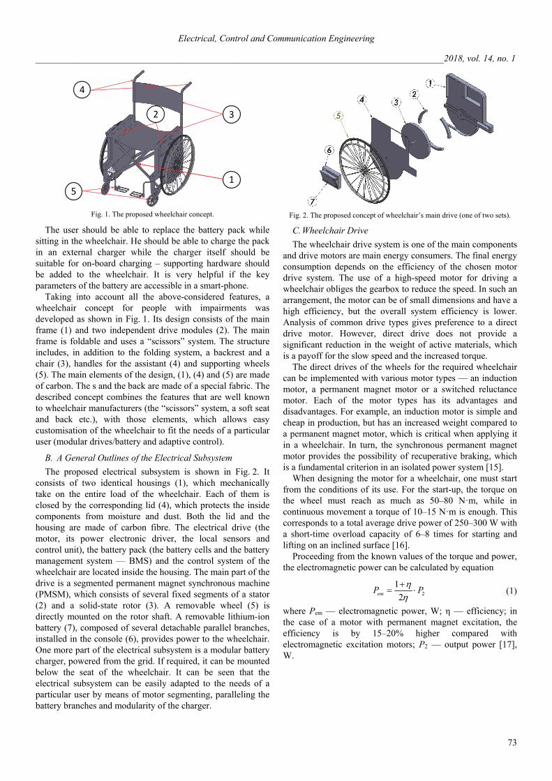
Fig. 1. The proposed wheelchair concept.
The user should be able to replace the battery pack while sitting in the wheelchair. He should be able to charge the pack in an external charger while the charger itself should be suitable for on-board charging – supporting hardware should be added to the wheelchair. It is very helpful if the key parameters of the battery are accessible in a smart-phone.
Taking into account all the above-considered features, a wheelchair concept for people with impairments was developed as shown in Fig. 1. Its design consists of the main frame (1) and two independent drive modules (2). The main frame is foldable and uses a “scissors” system. The structure includes, in addition to the folding system, a backrest and a chair (3), handles for the assistant (4) and supporting wheels (5). The main elements of the design, (1), (4) and (5) are made of carbon. The s and the back are made of a special fabric. The described concept combines the features that are well known to wheelchair manufacturers (the “scissors” system, a soft seat and back etc.), with those elements, which allows easy customisation of the wheelchair to fit the needs of a particular user (modular drives/battery and adaptive control).
B. A General Outlines of the Electrical Subsystem
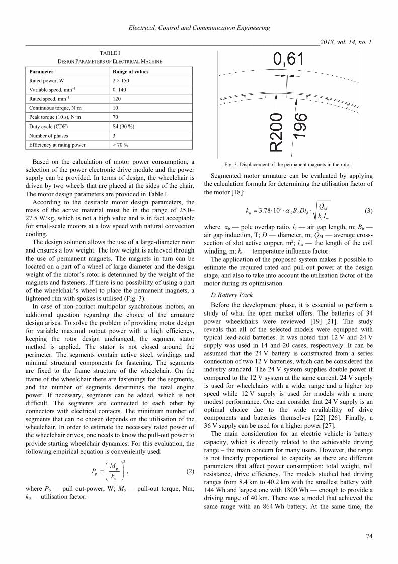
The proposed electrical subsystem is shown in Fig. 2. It consists of two identical housings (1), which mechanically take on the entire load of the wheelchair. Each of them is closed by the corresponding lid (4), which protects the inside components from moisture and dust. Both the lid and the housing are made of carbon fibre. The electrical drive (the motor, its power electronic driver, the local sensors and control unit), the battery pack (the battery cells and the battery management system — BMS) and the control system of the wheelchair are located inside the housing. The main part of the drive is a segmented permanent magnet synchronous machine (PMSM), which consists of several fixed segments of a stator (2) and a solid-state rotor (3). A removable wheel (5) is directly mounted on the rotor shaft. A removable lithium-ion battery (7), composed of several detachable parallel branches, installed in the console (6), provides power to the wheelchair. One more part of the electrical subsystem is a modular battery charger, powered from the grid. If required, it can be mounted below the seat of the wheelchair. It can be seen that the electrical subsystem can be easily adapted to the needs of a particular user by means of motor segmenting, paralleling the battery branches and modularity of the charger.
Fig. 2. The proposed concept of wheelchair’s main drive (one of two sets).
C. Wheelchair Drive
The wheelchair drive system is one of the main components and drive motors are main energy consumers. The final energy consumption depends on the efficiency of the chosen motor drive system. The use of a high-speed motor for driving a wheelchair obliges the gearbox to reduce the speed. In such an arrangement, the motor can be of small dimensions and have a high efficiency, but the overall system efficiency is lower. Analysis of common drive types gives preference to a direct drive motor. However, direct drive does not provide a significant reduction in the weight of active materials, which is a payoff for the slow speed and the increased torque.
The direct drives of the wheels for the required wheelchair can be implemented with various motor types — an induction motor, a permanent magnet motor or a switched reluctance motor. Each of the motor types has its advantages and disadvantages. For example, an induction motor is simple and cheap in production, but has an increased weight compared to a permanent magnet motor, which is critical when applying it in a wheelchair. In turn, the synchronous permanent magnet motor provides the possibility of recuperative braking, which is a fundamental criterion in an isolated power system [15].
When designing the motor for a wheelchair, one must start from the conditions of its use. For the start-up, the torque on the wheel must reach as much as 50–80 Nꞏm, while in continuous movement a torque of 10–15 Nꞏm is enough. This corresponds to a total average drive power of 250–300 W with a short-time overload capacity of 6–8 times for starting and lifting on an inclined surface [16].
Proceeding from the known values of the torque and power, the electromagnetic power can be calculated by equation
2
1
2emP P
(1)
where Pem — electromagnetic power, W; η — efficiency; in the case of a motor with permanent magnet excitation, the efficiency is by 15–20% higher compared with electromagnetic excitation motors; P2 — output power [17], W.
Electrical, Control and Communication Engineering
________________________________________________________________________________________2018, vol. 14, no. 1
74
TABLE I
DESIGN PARAMETERS OF ELECTRICAL MACHINE
Parameter Range of values
Rated power, W 2 × 150
Variable speed, min–1 0–140
Rated speed, min–1 120
Continuous torque, Nꞏm 10
Peak torque (10 s), Nꞏm 70
Duty cycle (CDF) S4 (90 %)
Number of phases 3
Efficiency at rating power > 70 %
Based on the calculation of motor power consumption, a
selection of the power electronic drive module and the power supply can be provided. In terms of design, the wheelchair is driven by two wheels that are placed at the sides of the chair. The motor design parameters are provided in Table I.
According to the desirable motor design parameters, the mass of the active material must be in the range of 25.0–27.5 W/kg, which is not a high value and is in fact acceptable for small-scale motors at a low speed with natural convection cooling.
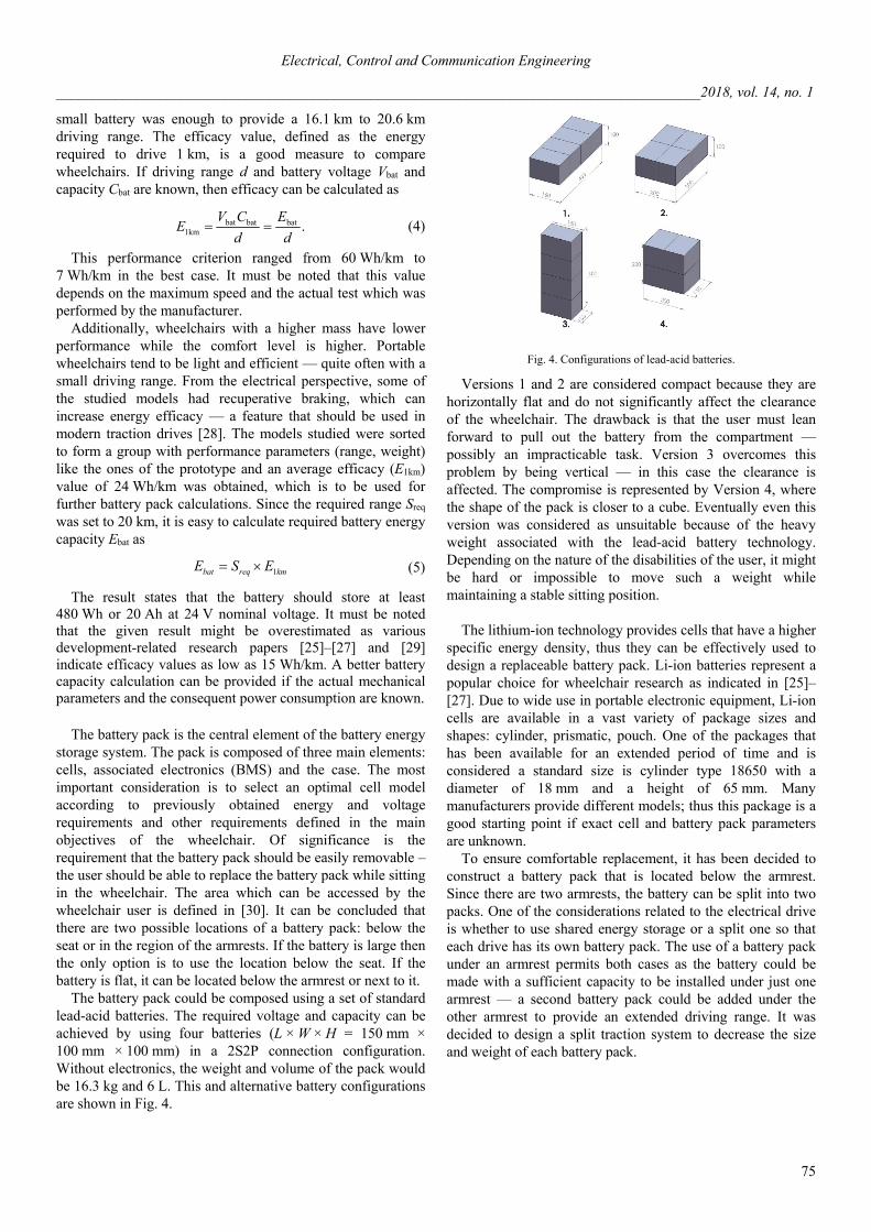
The design solution allows the use of a large-diameter rotor and ensures a low weight. The low weight is achieved through the use of permanent magnets. The magnets in turn can be located on a part of a wheel of large diameter and the design weight of the motor’s rotor is determined by the weight of the magnets and fasteners. If there is no possibility of using a part of the wheelchair’s wheel to place the permanent magnets, a lightened rim with spokes is utilised (Fig. 3).
In case of non-contact multipolar synchronous motors, an additional question regarding the choice of the armature design arises. To solve the problem of providing motor design for variable maximal output power with a high efficiency, keeping the rotor design unchanged, the segment stator method is applied. The stator is not closed around the perimeter. The segments contain active steel, windings and minimal structural components for fastening. The segments are fixed to the frame structure of the wheelchair. On the frame of the wheelchair there are fastenings for the segments, and the number of segments determines the total engine power. If necessary, segments can be added, which is not difficult. The segments are connected to each other by connectors with electrical contacts. The minimum number of segments that can be chosen depends on the utilisation of the wheelchair. In order to estimate the necessary rated power of the wheelchair drives, one needs to know the pull-out power to provide starting wheelchair dynamics. For this evaluation, the following empirical equation is conveniently used:
2
pp
u
,M
Pk
(2)
where Pp — pull out-power, W; Mp — pull-out torque, Nm; ku — utilisation factor.
Fig. 3. Displacement of the permanent magnets in the rotor.
Segmented motor armature can be evaluated by applying the calculation formula for determining the utilisation factor of the motor [18]:
33.78 10 Mu
t m
Qk B Dl
k l (3)
where αδ — pole overlap ratio, lδ — air gap length, m; Bδ — air gap induction, T; D — diameter, m; QM — average cross-section of slot active copper, m2; lm — the length of the coil winding, m; kt — temperature influence factor.
The application of the proposed system makes it possible to estimate the required rated and pull-out power at the design stage, and also to take into account the utilisation factor of the motor during its optimisation.
D. Battery Pack
Before the development phase, it is essential to perform a study of what the open market offers. The batteries of 34 power wheelchairs were reviewed [19]–[21]. The study reveals that all of the selected models were equipped with typical lead-acid batteries. It was noted that 12 V and 24 V supply was used in 14 and 20 cases, respectively. It can be assumed that the 24 V battery is constructed from a series connection of two 12 V batteries, which can be considered the industry standard. The 24 V system supplies double power if compared to the 12 V system at the same current. 24 V supply is used for wheelchairs with a wider range and a higher top speed while 12 V supply is used for models with a more modest performance. One can consider that 24 V supply is an optimal choice due to the wide availability of drive components and batteries themselves [22]–[26]. Finally, a 36 V supply can be used for a higher power [27].
The main consideration for an electric vehicle is battery capacity, which is directly related to the achievable driving range – the main concern for many users. However, the range is not linearly proportional to capacity as there are different parameters that affect power consumption: total weight, roll resistance, drive efficiency. The models studied had driving ranges from 8.4 km to 40.2 km with the smallest battery with 144 Wh and largest one with 1800 Wh — enough to provide a driving range of 40 km. There was a model that achieved the same range with an 864 Wh battery. At the same time, the
Electrical, Control and Communication Engineering
________________________________________________________________________________________2018, vol. 14, no. 1
75
small battery was enough to provide a 16.1 km to 20.6 km driving range. The efficacy value, defined as the energy required to drive 1 km, is a good measure to compare wheelchairs. If driving range d and battery voltage Vbat and capacity Cbat are known, then efficacy can be calculated as
bat bat bat1km .
V C EE
d d (4)
This performance criterion ranged from 60 Wh/km to 7 Wh/km in the best case. It must be noted that this value depends on the maximum speed and the actual test which was performed by the manufacturer.
Additionally, wheelchairs with a higher mass have lower performance while the comfort level is higher. Portable wheelchairs tend to be light and efficient — quite often with a small driving range. From the electrical perspective, some of the studied models had recuperative braking, which can increase energy efficacy — a feature that should be used in modern traction drives [28]. The models studied were sorted to form a group with performance parameters (range, weight) like the ones of the prototype and an average efficacy (E1km) value of 24 Wh/km was obtained, which is to be used for further battery pack calculations. Since the required range Sreq was set to 20 km, it is easy to calculate required battery energy capacity Ebat as
1bat req kmE S E (5)
The result states that the battery should store at least 480 Wh or 20 Ah at 24 V nominal voltage. It must be noted that the given result might be overestimated as various development-related research papers [25]–[27] and [29] indicate efficacy values as low as 15 Wh/km. A better battery capacity calculation can be provided if the actual mechanical parameters and the consequent power consumption are known.
The battery pack is the central element of the battery energy
storage system. The pack is composed of three main elements: cells, associated electronics (BMS) and the case. The most important consideration is to select an optimal cell model according to previously obtained energy and voltage requirements and other requirements defined in the main objectives of the wheelchair. Of significance is the requirement that the battery pack should be easily removable – the user should be able to replace the battery pack while sitting in the wheelchair. The area which can be accessed by the wheelchair user is defined in [30]. It can be concluded that there are two possible locations of a battery pack: below the seat or in the region of the armrests. If the battery is large then the only option is to use the location below the seat. If the battery is flat, it can be located below the armrest or next to it.
The battery pack could be composed using a set of standard lead-acid batteries. The required voltage and capacity can be achieved by using four batteries (L × W × H = 150 mm × 100 mm × 100 mm) in a 2S2P connection configuration. Without electronics, the weight and volume of the pack would be 16.3 kg and 6 L. This and alternative battery configurations are shown in Fig. 4.
Fig. 4. Configurations of lead-acid batteries.
Versions 1 and 2 are considered compact because they are horizontally flat and do not significantly affect the clearance of the wheelchair. The drawback is that the user must lean forward to pull out the battery from the compartment — possibly an impracticable task. Version 3 overcomes this problem by being vertical — in this case the clearance is affected. The compromise is represented by Version 4, where the shape of the pack is closer to a cube. Eventually even this version was considered as unsuitable because of the heavy weight associated with the lead-acid battery technology. Depending on the nature of the disabilities of the user, it might be hard or impossible to move such a weight while maintaining a stable sitting position.
The lithium-ion technology provides cells that have a higher
specific energy density, thus they can be effectively used to design a replaceable battery pack. Li-ion batteries represent a popular choice for wheelchair research as indicated in [25]–[27]. Due to wide use in portable electronic equipment, Li-ion cells are available in a vast variety of package sizes and shapes: cylinder, prismatic, pouch. One of the packages that has been available for an extended period of time and is considered a standard size is cylinder type 18650 with a diameter of 18 mm and a height of 65 mm. Many manufacturers provide different models; thus this package is a good starting point if exact cell and battery pack parameters are unknown.
To ensure comfortable replacement, it has been decided to construct a battery pack that is located below the armrest. Since there are two armrests, the battery can be split into two packs. One of the considerations related to the electrical drive is whether to use shared energy storage or a split one so that each drive has its own battery pack. The use of a battery pack under an armrest permits both cases as the battery could be made with a sufficient capacity to be installed under just one armrest — a second battery pack could be added under the other armrest to provide an extended driving range. It was decided to design a split traction system to decrease the size and weight of each battery pack.
Electrical, Control and Communication Engineering
________________________________________________________________________________________2018, vol. 14, no. 1
76
TABLE II
COMPARISON OF FOUR CELL MODELS
No. Cell capacity, Ah
Cell voltage, V
Pack voltage, V
Pack capacity, Wh
Optimal configuration
1 3.30 3.600 25.2 332 7S3P
2 3.35 3.600 25.2 337 7S3P
3 3.13 3.600 25.2 315 7S4P
4 3.50 3.635 25.4 356 7S3P
Fig. 5. Physical configuration of Li-ion battery pack.
18650 type cells usually have 3.6 V nominal voltage while the capacity varies from below 1.5 Ah to above 3.5 Ah. The typical cycle life of these cells is 300 to 500 cycles. Development of a relatively small and lightweight battery pack requires that the cell capacity is at least 3 Ah. Since the storage system is split, the required capacity for each pack is 240 Wh. To provide flexibility for future development, it was assumed that each cell is rated for 3 Ah at 3.6 V, or 10.8 Wh, which results in 7S4P configuration — 28 cells per pack. Four cell models from different manufacturers were selected to perform further performance testing. A brief comparison is given in Table II. One can see that the obtained pack capacity is larger than required. The last column provides an optimized configuration — using high capacity cells can decrease the total cell count. Such cells weigh 45–50 g each or 1.26–1.4 kg in total. It can be estimated that such a weight can be easily moved by the user. The given 28 cells can be split into two vertical layers with each layer composed of 3 × 5 cells (Fig. 5). The case is equipped with a carrying handle and the cut-out shows the cell orientation. The battery will be located below the armrest so that it is accessible from the outer side. It is expected that the main features of BMS such as cell monitoring, balancing and state-of-charge estimation [31], will be implemented in the battery pack.
TABLE III
HIERARCHY OF CONTROL FUNCTIONS
Level Function
1 Direct/indirect user interface – defining the direction and speed of wheelchair movement, ensuring safety of movement
2 Human-In-The-Loop system – forming direct/indirect control commands, providing the (pseudo-)bionic feedback on their execution
3 Local control involving actuators and sensors
E. Outlines of Sensor Use
Several groups of sensors need to be used in the considered wheelchairs. The first group consists of local sensors that are needed for successful operation of the electrical drive and the battery pack. For example, Field-Oriented Control (FOC) requires information about actual stator voltages and currents at the motor terminals [32]. The second group includes such sensors as acceleration sensors, angle, position and other sensors, required for safe movement of the wheelchair. Finally, such devices as EMG and EOG sensors facilitate the development of a Human-In-The-Loop (HITL) system that involves the wheelchair and its user. It is reasonable to combine these sensors in one sensor network.
An auxiliary function of such a network is collecting the data from sensors and sending them to a distant server, where they are processed and analysed in order to find out the state of the wheelchair as well as its speed and the distance that the wheelchair has accomplished over a period of time [33].
Sensor networks can also forecast the road situation, which allows optimising and predicting how the wheelchair is going to move in different scenarios (for example, modifies the control algorithm of the wheelchair drives if the road situation changes). It is also possible to utilise this method even if some sensors are not available, obtaining the same accuracy of prediction as when using all the sensors [34].
F. The Wheelchair Control System
The proposed concept of the wheelchair assumes several levels of its control depending on the importance of the function and their interaction (Table III). At the highest level there is the wheelchair user, who sets the direction of movement or its destination point. To do this, the wheelchair user utilises the most suitable interface — a joystick, accelerometers, EMG or electroencephalography (EEG).
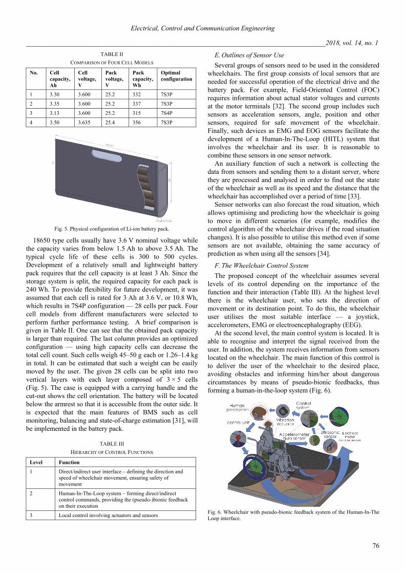
At the second level, the main control system is located. It is able to recognise and interpret the signal received from the user. In addition, the system receives information from sensors located on the wheelchair. The main function of this control is to deliver the user of the wheelchair to the desired place, avoiding obstacles and informing him/her about dangerous circumstances by means of pseudo-bionic feedbacks, thus forming a human-in-the-loop system (Fig. 6).
Fig. 6. Wheelchair with pseudo-bionic feedback system of the Human-In-The Loop interface.
Electrical, Control and Communication Engineering
________________________________________________________________________________________2018, vol. 14, no. 1
77
This part of the control system also includes a network of sensors, which collects information about the environment (ultrasonic and infrared sensors), the state of the wheelchair (gyroscope and accelerometer). The information from the sensors processed by the main control unit and passed to the local control units. In case of a dangerous situation (collision, possible falling) the main control unit activates pseudo-bionic feedbacks (typically, sends a coded vibration signal to the user). Physically, this part of the control system can be located in the right rack or the left one, depending on the needs of the user and on where it is more convenient to connect the control interfaces and sensors. It is also possible to install two control cards in different racks. To ensure the control of the drives and the integration of the two control modules, a soft multicore cable is installed in the chair for communication.
An artificial neural network (ANN) is proposed to adapt the main control unit and the sensor network to the needs of the particular wheelchair user. The algorithms of deep learning must be applied to ensure correct operation of the ANN. It is assumed that the ANN learning occurs individually for each user. Initially, a set of basic commands is activated. Then, as long as the wheelchair is used, the ANN will adapt the control system to a particular user.
Finally, the lowest level of the control hierarchy contains the units intended to control the electrical drive and the battery pack, to form pseudo-bionic feedbacks and to collect information form sensors. For example, each segment of the motor stator is controlled by a dedicated microcontroller. Its main function is providing the torque and speed according to the reference received from the main controller. These and other local microcontrollers are connected to the main module by means of industrial interface RS485.
G. The Battery Charger
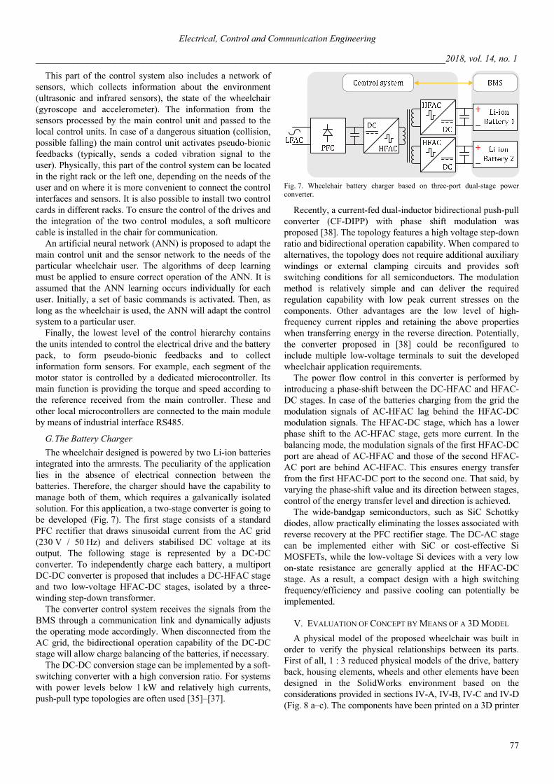
The wheelchair designed is powered by two Li-ion batteries integrated into the armrests. The peculiarity of the application lies in the absence of electrical connection between the batteries. Therefore, the charger should have the capability to manage both of them, which requires a galvanically isolated solution. For this application, a two-stage converter is going to be developed (Fig. 7). The first stage consists of a standard PFC rectifier that draws sinusoidal current from the AC grid (230 V / 50 Hz) and delivers stabilised DC voltage at its output. The following stage is represented by a DC-DC converter. To independently charge each battery, a multiport DC-DC converter is proposed that includes a DC-HFAC stage and two low-voltage HFAC-DC stages, isolated by a three-winding step-down transformer.
The converter control system receives the signals from the BMS through a communication link and dynamically adjusts the operating mode accordingly. When disconnected from the AC grid, the bidirectional operation capability of the DC-DC stage will allow charge balancing of the batteries, if necessary.
The DC-DC conversion stage can be implemented by a soft-switching converter with a high conversion ratio. For systems with power levels below 1 kW and relatively high currents, push-pull type topologies are often used [35]–[37].
Fig. 7. Wheelchair battery charger based on three-port dual-stage power converter.
Recently, a current-fed dual-inductor bidirectional push-pull converter (CF-DIPP) with phase shift modulation was proposed [38]. The topology features a high voltage step-down ratio and bidirectional operation capability. When compared to alternatives, the topology does not require additional auxiliary windings or external clamping circuits and provides soft switching conditions for all semiconductors. The modulation method is relatively simple and can deliver the required regulation capability with low peak current stresses on the components. Other advantages are the low level of high-frequency current ripples and retaining the above properties when transferring energy in the reverse direction. Potentially, the converter proposed in [38] could be reconfigured to include multiple low-voltage terminals to suit the developed wheelchair application requirements.
The power flow control in this converter is performed by introducing a phase-shift between the DC-HFAC and HFAC-DC stages. In case of the batteries charging from the grid the modulation signals of AC-HFAC lag behind the HFAC-DC modulation signals. The HFAC-DC stage, which has a lower phase shift to the AC-HFAC stage, gets more current. In the balancing mode, the modulation signals of the first HFAC-DC port are ahead of AC-HFAC and those of the second HFAC-AC port are behind AC-HFAC. This ensures energy transfer from the first HFAC-DC port to the second one. That said, by varying the phase-shift value and its direction between stages, control of the energy transfer level and direction is achieved.
The wide-bandgap semiconductors, such as SiC Schottky diodes, allow practically eliminating the losses associated with reverse recovery at the PFC rectifier stage. The DC-AC stage can be implemented either with SiC or cost-effective Si MOSFETs, while the low-voltage Si devices with a very low on-state resistance are generally applied at the HFAC-DC stage. As a result, a compact design with a high switching frequency/efficiency and passive cooling can potentially be implemented.
V. EVALUATION OF CONCEPT BY MEANS OF A 3D MODEL
A physical model of the proposed wheelchair was built in order to verify the physical relationships between its parts. First of all, 1 : 3 reduced physical models of the drive, battery back, housing elements, wheels and other elements have been designed in the SolidWorks environment based on the considerations provided in sections IV-A, IV-B, IV-C and IV-D (Fig. 8 a–c). The components have been printed on a 3D printer
Electrical, Control and Communication Engineering
________________________________________________________________________________________2018, vol. 14, no. 1
78
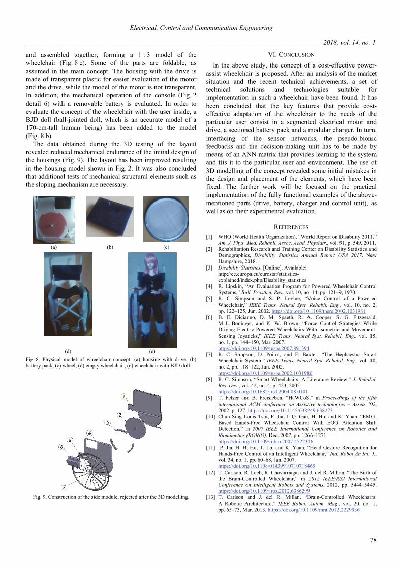
and assembled together, forming a 1 : 3 model of the wheelchair (Fig. 8 c). Some of the parts are foldable, as assumed in the main concept. The housing with the drive is made of transparent plastic for easier evaluation of the motor and the drive, while the model of the motor is not transparent. In addition, the mechanical operation of the console (Fig. 2 detail 6) with a removable battery is evaluated. In order to evaluate the concept of the wheelchair with the user inside, a BJD doll (ball-jointed doll, which is an accurate model of a 170-cm-tall human being) has been added to the model (Fig. 8 b).
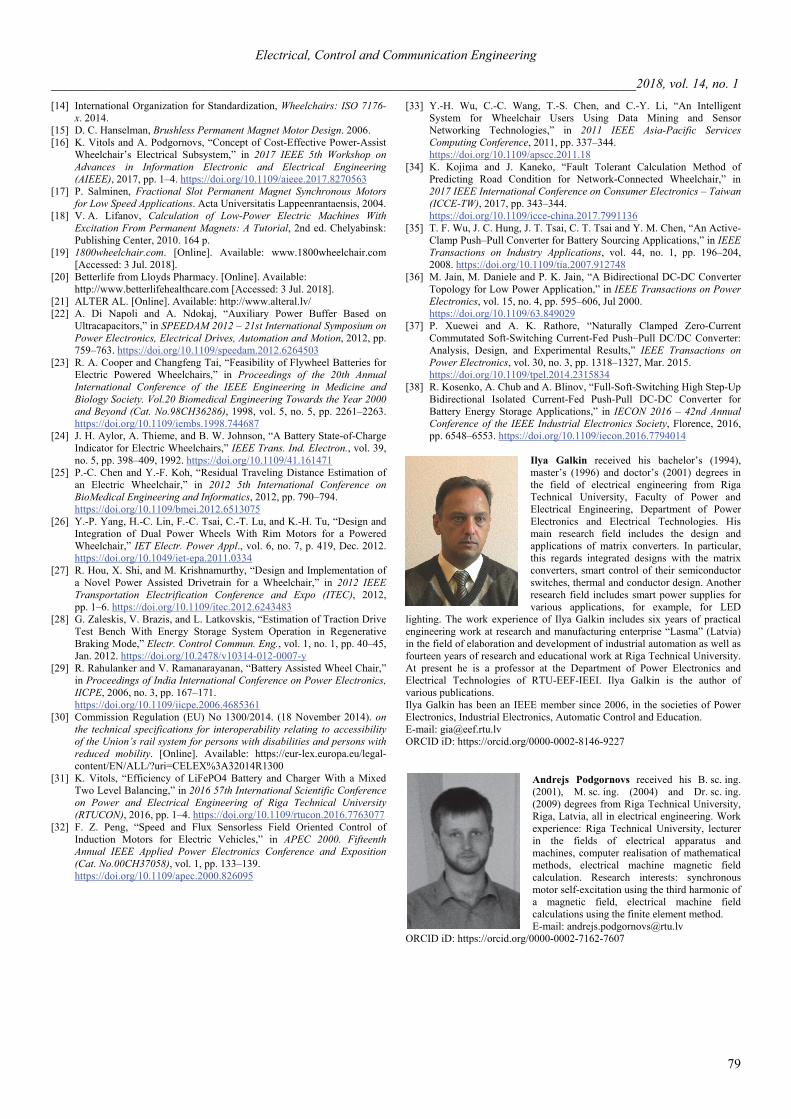
The data obtained during the 3D testing of the layout revealed reduced mechanical endurance of the initial design of the housings (Fig. 9). The layout has been improved resulting in the housing model shown in Fig. 2. It was also concluded that additional tests of mechanical structural elements such as the sloping mechanism are necessary.
(a) (b) (c)
(d) (e)
Fig. 8. Physical model of wheelchair concept: (a) housing with drive, (b) battery pack, (c) wheel, (d) empty wheelchair, (e) wheelchair with BJD doll.
Fig. 9. Construction of the side module, rejected after the 3D modelling.
VI. CONCLUSION
In the above study, the concept of a cost-effective power-assist wheelchair is proposed. After an analysis of the market situation and the recent technical achievements, a set of technical solutions and technologies suitable for implementation in such a wheelchair have been found. It has been concluded that the key features that provide cost-effective adaptation of the wheelchair to the needs of the particular user consist in a segmented electrical motor and drive, a sectioned battery pack and a modular charger. In turn, interfacing of the sensor networks, the pseudo-bionic feedbacks and the decision-making unit has to be made by means of an ANN matrix that provides learning to the system and fits it to the particular user and environment. The use of 3D modelling of the concept revealed some initial mistakes in the design and placement of the elements, which have been fixed. The further work will be focused on the practical implementation of the fully functional examples of the above-mentioned parts (drive, battery, charger and control unit), as well as on their experimental evaluation.
REFERENCES [1] WHO (World Health Organization), “World Report on Disability 2011,”
Am. J. Phys. Med. Rehabil. Assoc. Acad. Physiatr., vol. 91, p. 549, 2011. [2] Rehabilitation Research and Training Center on Disability Statistics and
Demographics, Disability Statistics Annual Report USA 2017. New Hampshire, 2018.
[3] Disability Statistics. [Online]. Available: http://ec.europa.eu/eurostat/statistics-explained/index.php/Disability_statistics
[4] R. Lipskin, “An Evaluation Program for Powered Wheelchair Control Systems,” Bull. Prosthet. Res., vol. 10, no. 14, pp. 121–9, 1970.
[5] R. C. Simpson and S. P. Levine, “Voice Control of a Powered Wheelchair,” IEEE Trans. Neural Syst. Rehabil. Eng., vol. 10, no. 2, pp. 122–125, Jun. 2002. https://doi.org/10.1109/tnsre.2002.1031981
[6] B. E. Dicianno, D. M. Spaeth, R. A. Cooper, S. G. Fitzgerald, M. L. Boninger, and K. W. Brown, “Force Control Strategies While Driving Electric Powered Wheelchairs With Isometric and Movement-Sensing Joysticks,” IEEE Trans. Neural Syst. Rehabil. Eng., vol. 15, no. 1, pp. 144–150, Mar. 2007. https://doi.org/10.1109/tnsre.2007.891394
[7] R. C. Simpson, D. Poirot, and F. Baxter, “The Hephaestus Smart Wheelchair System,” IEEE Trans. Neural Syst. Rehabil. Eng., vol. 10, no. 2, pp. 118–122, Jun. 2002. https://doi.org/10.1109/tnsre.2002.1031980
[8] R. C. Simpson, “Smart Wheelchairs: A Literature Review,” J. Rehabil. Res. Dev., vol. 42, no. 4, p. 423, 2005. https://doi.org/10.1682/jrrd.2004.08.0101
[9] T. Felzer and B. Freisleben, “HaWCoS,” in Proceedings of the fifth international ACM conference on Assistive technologies – Assets ’02, 2002, p. 127. https://doi.org/10.1145/638249.638273
[10] Chun Sing Louis Tsui, P. Jia, J. Q. Gan, H. Hu, and K. Yuan, “EMG-Based Hands-Free Wheelchair Control With EOG Attention Shift Detection,” in 2007 IEEE International Conference on Robotics and Biomimetics (ROBIO), Dec. 2007, pp. 1266–1271. https://doi.org/10.1109/robio.2007.4522346
[11] P. Jia, H. H. Hu, T. Lu, and K. Yuan, “Head Gesture Recognition for Hands‐Free Control of an Intelligent Wheelchair,” Ind. Robot An Int. J., vol. 34, no. 1, pp. 60–68, Jan. 2007. https://doi.org/10.1108/01439910710718469
[12] T. Carlson, R. Leeb, R. Chavarriaga, and J. del R. Millan, “The Birth of the Brain-Controlled Wheelchair,” in 2012 IEEE/RSJ International Conference on Intelligent Robots and Systems, 2012, pp. 5444–5445. https://doi.org/10.1109/iros.2012.6386299
[13] T. Carlson and J. del R. Millan, “Brain-Controlled Wheelchairs: A Robotic Architecture,” IEEE Robot. Autom. Mag., vol. 20, no. 1, pp. 65–73, Mar. 2013. https://doi.org/10.1109/mra.2012.2229936
Electrical, Control and Communication Engineering
________________________________________________________________________________________2018, vol. 14, no. 1
79
[14] International Organization for Standardization, Wheelchairs: ISO 7176-x. 2014.
[15] D. C. Hanselman, Brushless Permanent Magnet Motor Design. 2006. [16] K. Vitols and A. Podgornovs, “Concept of Cost-Effective Power-Assist
Wheelchair’s Electrical Subsystem,” in 2017 IEEE 5th Workshop on Advances in Information Electronic and Electrical Engineering (AIEEE), 2017, pp. 1–4. https://doi.org/10.1109/aieee.2017.8270563
[17] P. Salminen, Fractional Slot Permanent Magnet Synchronous Motors for Low Speed Applications. Acta Universitatis Lappeenrantaensis, 2004.
[18] V. А. Lifanov, Calculation of Low-Power Electric Machines With Excitation From Permanent Magnets: A Tutorial, 2nd ed. Chelyabinsk: Publishing Center, 2010. 164 p.
[19] 1800wheelchair.com. [Online]. Available: www.1800wheelchair.com [Accessed: 3 Jul. 2018].
[20] Betterlife from Lloyds Pharmacy. [Online]. Available: http://www.betterlifehealthcare.com [Accessed: 3 Jul. 2018].
[21] ALTER AL. [Online]. Available: http://www.alteral.lv/ [22] A. Di Napoli and A. Ndokaj, “Auxiliary Power Buffer Based on
Ultracapacitors,” in SPEEDAM 2012 – 21st International Symposium on Power Electronics, Electrical Drives, Automation and Motion, 2012, pp. 759–763. https://doi.org/10.1109/speedam.2012.6264503
[23] R. A. Cooper and Changfeng Tai, “Feasibility of Flywheel Batteries for Electric Powered Wheelchairs,” in Proceedings of the 20th Annual International Conference of the IEEE Engineering in Medicine and Biology Society. Vol.20 Biomedical Engineering Towards the Year 2000 and Beyond (Cat. No.98CH36286), 1998, vol. 5, no. 5, pp. 2261–2263. https://doi.org/10.1109/iembs.1998.744687
[24] J. H. Aylor, A. Thieme, and B. W. Johnson, “A Battery State-of-Charge Indicator for Electric Wheelchairs,” IEEE Trans. Ind. Electron., vol. 39, no. 5, pp. 398–409, 1992. https://doi.org/10.1109/41.161471
[25] P.-C. Chen and Y.-F. Koh, “Residual Traveling Distance Estimation of an Electric Wheelchair,” in 2012 5th International Conference on BioMedical Engineering and Informatics, 2012, pp. 790–794. https://doi.org/10.1109/bmei.2012.6513075
[26] Y.-P. Yang, H.-C. Lin, F.-C. Tsai, C.-T. Lu, and K.-H. Tu, “Design and Integration of Dual Power Wheels With Rim Motors for a Powered Wheelchair,” IET Electr. Power Appl., vol. 6, no. 7, p. 419, Dec. 2012. https://doi.org/10.1049/iet-epa.2011.0334
[27] R. Hou, X. Shi, and M. Krishnamurthy, “Design and Implementation of a Novel Power Assisted Drivetrain for a Wheelchair,” in 2012 IEEE Transportation Electrification Conference and Expo (ITEC), 2012, pp. 1–6. https://doi.org/10.1109/itec.2012.6243483
[28] G. Zaleskis, V. Brazis, and L. Latkovskis, “Estimation of Traction Drive Test Bench With Energy Storage System Operation in Regenerative Braking Mode,” Electr. Control Commun. Eng., vol. 1, no. 1, pp. 40–45, Jan. 2012. https://doi.org/10.2478/v10314-012-0007-y
[29] R. Rahulanker and V. Ramanarayanan, “Battery Assisted Wheel Chair,” in Proceedings of India International Conference on Power Electronics, IICPE, 2006, no. 3, pp. 167–171. https://doi.org/10.1109/iicpe.2006.4685361
[30] Commission Regulation (EU) No 1300/2014. (18 November 2014). on the technical specifications for interoperability relating to accessibility of the Union’s rail system for persons with disabilities and persons with reduced mobility. [Online]. Available: https://eur-lex.europa.eu/legal-content/EN/ALL/?uri=CELEX%3A32014R1300
[31] K. Vitols, “Efficiency of LiFePO4 Battery and Charger With a Mixed Two Level Balancing,” in 2016 57th International Scientific Conference on Power and Electrical Engineering of Riga Technical University (RTUCON), 2016, pp. 1–4. https://doi.org/10.1109/rtucon.2016.7763077
[32] F. Z. Peng, “Speed and Flux Sensorless Field Oriented Control of Induction Motors for Electric Vehicles,” in APEC 2000. Fifteenth Annual IEEE Applied Power Electronics Conference and Exposition (Cat. No.00CH37058), vol. 1, pp. 133–139. https://doi.org/10.1109/apec.2000.826095
[33] Y.-H. Wu, C.-C. Wang, T.-S. Chen, and C.-Y. Li, “An Intelligent System for Wheelchair Users Using Data Mining and Sensor Networking Technologies,” in 2011 IEEE Asia-Pacific Services Computing Conference, 2011, pp. 337–344. https://doi.org/10.1109/apscc.2011.18
[34] K. Kojima and J. Kaneko, “Fault Tolerant Calculation Method of Predicting Road Condition for Network-Connected Wheelchair,” in 2017 IEEE International Conference on Consumer Electronics – Taiwan (ICCE-TW), 2017, pp. 343–344. https://doi.org/10.1109/icce-china.2017.7991136
[35] T. F. Wu, J. C. Hung, J. T. Tsai, C. T. Tsai and Y. M. Chen, “An Active-Clamp Push–Pull Converter for Battery Sourcing Applications,” in IEEE Transactions on Industry Applications, vol. 44, no. 1, pp. 196–204, 2008. https://doi.org/10.1109/tia.2007.912748
[36] M. Jain, M. Daniele and P. K. Jain, “A Bidirectional DC-DC Converter Topology for Low Power Application,” in IEEE Transactions on Power Electronics, vol. 15, no. 4, pp. 595–606, Jul 2000. https://doi.org/10.1109/63.849029
[37] P. Xuewei and A. K. Rathore, “Naturally Clamped Zero-Current Commutated Soft-Switching Current-Fed Push–Pull DC/DC Converter: Analysis, Design, and Experimental Results,” IEEE Transactions on Power Electronics, vol. 30, no. 3, pp. 1318–1327, Mar. 2015. https://doi.org/10.1109/tpel.2014.2315834
[38] R. Kosenko, A. Chub and A. Blinov, “Full-Soft-Switching High Step-Up Bidirectional Isolated Current-Fed Push-Pull DC-DC Converter for Battery Energy Storage Applications,” in IECON 2016 – 42nd Annual Conference of the IEEE Industrial Electronics Society, Florence, 2016, pp. 6548–6553. https://doi.org/10.1109/iecon.2016.7794014
Ilya Galkin received his bachelor’s (1994), master’s (1996) and doctor’s (2001) degrees in the field of electrical engineering from Riga Technical University, Faculty of Power and Electrical Engineering, Department of Power Electronics and Electrical Technologies. His main research field includes the design and applications of matrix converters. In particular, this regards integrated designs with the matrix converters, smart control of their semiconductor switches, thermal and conductor design. Another research field includes smart power supplies for various applications, for example, for LED
lighting. The work experience of Ilya Galkin includes six years of practical engineering work at research and manufacturing enterprise “Lasma” (Latvia) in the field of elaboration and development of industrial automation as well as fourteen years of research and educational work at Riga Technical University. At present he is a professor at the Department of Power Electronics and Electrical Technologies of RTU-EEF-IEEI. Ilya Galkin is the author of various publications. Ilya Galkin has been an IEEE member since 2006, in the societies of Power Electronics, Industrial Electronics, Automatic Control and Education. E-mail: [email protected] ORCID iD: https://orcid.org/0000-0002-8146-9227
Andrejs Podgornovs received his B. sc. ing. (2001), M. sc. ing. (2004) and Dr. sc. ing. (2009) degrees from Riga Technical University, Riga, Latvia, all in electrical engineering. Work experience: Riga Technical University, lecturer in the fields of electrical apparatus and machines, computer realisation of mathematical methods, electrical machine magnetic field calculation. Research interests: synchronous motor self-excitation using the third harmonic of a magnetic field, electrical machine field calculations using the finite element method. E-mail: [email protected]
ORCID iD: https://orcid.org/0000-0002-7162-7607
Electrical, Control and Communication Engineering
________________________________________________________________________________________2018, vol. 14, no. 1
80
Andrei Blinov received the B. sc. and M. sc. degrees in electrical drives and power electronics and the Ph. D. degree, with a dissertation devoted to the research of switching properties and performance improvement methods of high-voltage IGBT-based DC-DC converters, from Tallinn University of Technology, Tallinn, Estonia, in 2005, 2008, and 2012, respectively. He is currently a Senior Researcher at the Department of Electrical Engineering, Tallinn University of Technology. His research interests are in modelling and
research of switch-mode power converters, advanced modulation techniques, new power semiconductor device technologies and semiconductor heat dissipation aspects. E-mail: [email protected] ORCID iD: https://orcid.org/0000-0001-8577-4897
Kristaps Vitols received B. sc. and M. sc. in electrical engineering from Riga Technical University, Riga, Latvia, in 2008 and 2010, respectively. Since 2008, he has been employed by the Institute of Industrial Electronics and Electrical Engineering of Riga Technical University. Current position: researcher. Research interests include traction control and power electronic converter design. Since 2009, he has been a member of the IEEE Power Electronics Society. E-mail: [email protected]
ORCID iD: https://orcid.org/0000-0002-7597-1093
Maxim Vorobyov received a B. sc. degree and a M. sc. degree in electrical engineering from Riga Technical University in 2009 and 2011, respectively. At present, he is a Ph.D. student at Riga Technical university. IEEE member since 2011. In 2012, he joined the Institute of Industrial Electronics and Electrical Engineering, where he is currently a researcher. His research interests include single-phase and multi-phase converters, matrix converters and energy storage devices. E-mail: [email protected] ORCID iD: https://orcid.org/0000-0001-5136-5905
Roman Kosenko (S’14) received the Dipl. eng. and M. sc. degrees in electronics from the Department of Industrial Electronics, Chernihiv State University of Technology, Chernihiv, Ukraine, in 2011 and 2013, respectively. He is currently working toward the Ph. D. degree at the Power Electronics Group, Department of Electrical Power Engineering and Mechatronics, Tallinn University (Estonia), and at the Biomedical Radioelectronic Apparatus and Systems Department of Chernihiv National University of Technology (Ukraine). His fields of interest include research, design and
simulation of switch mode converters for distributed power generation systems. He is author or co-author of over 20 scientific papers and is the holder of one utility model in the field of power electronics. Address: Department of Electrical Engineering, Tallinn University of Technology, Ehitajate tee 5, 12616 Tallinn, Estonia. E-mail: [email protected] ORCID iD: https://orcid.org/0000-0002-6214-3790
Related Documents