Considerations on the implementation and modeling of an active mass driver with electric torsional servomotor Filippo Ubertini n , Ilaria Venanzi, Gabriele Comanducci Department of Civil and Environmental Engineering, University of Perugia, Perugia, Italy article info Article history: Received 7 May 2013 Received in revised form 12 December 2014 Accepted 23 December 2014 Keywords: Active structural control Active mass driver system Electric torsional servomotor Control structure interaction Root-locus of closed-loop system abstract The current trend in full-scale applications of active mass drivers for mitigating buildings' vibrations is to rely on the use of electric servomotors and low friction transmission devices. While similar full-scale applications have been recently documented, there is still the need for deepening the understanding of the behavior of such active mass drivers, especially as it concerns their reliability in the case of extreme loading events. This paper presents some considerations arisen in the physical implementation of a prototype active mass driver system, fabricated by coupling an electric torsional servomotor with a ball screw transmission device, using state-of-the-art electronics and a high speed digital communication protocol between controller and servomotor drive. The prototype actuator is mounted on top of a scaled-down five-story frame structure, subjected to base excitation provided by a sliding table actuated by an electrodynamic shaker. The equations of motion are rigorously derived, at first, by considering the torque of the servomotor as the control input, in agreement with other literature work. Then, they are extended to the case where the servomotor operates under kinematic control, that is, by commanding its angular velocity instead of its torque, including control- structure-interaction effects. Experiments are carried out by employing an inherently stable collocated skyhook control algorithm, proving, on the one hand, the control effectiveness of the device but also revealing, on the other hand, the possibility of closed-loop system instability at high gains. Theoretical interpretation of the results clarifies that the dynamic behavior of the actuator plays a central role in determining its control effectiveness and is responsible for the observed stability issues, operating similarly to time delay effects. Numerical extension to the case of earthquake excitation confirms the control effectiveness of the device and highlights that different controllers essentially provide similar performances in the mitigation of the structural response. & 2014 Elsevier Ltd. All rights reserved. 1. Introduction Flexible civil engineering structures, like bridges and tall buildings, may experience significant levels of vibration under wind and seismic loads [1]. Response control strategies can be employed to mitigate such vibrations by providing additional damping capabilities [2–6]. Among the various available solutions for structural control, active systems are, in principle, the Contents lists available at ScienceDirect journal homepage: www.elsevier.com/locate/ymssp Mechanical Systems and Signal Processing http://dx.doi.org/10.1016/j.ymssp.2014.12.010 0888-3270/& 2014 Elsevier Ltd. All rights reserved. n Corresponding author. Tel.: þ39 075 585 3954, fax: þ39 075 585 3897. E-mail address: [email protected] (F. Ubertini). Mechanical Systems and Signal Processing ] (]]]]) ]]]–]]] Please cite this article as: F. Ubertini, et al., Considerations on the implementation and modeling of an active mass driver with electric torsional servomotor, Mech. Syst. Signal Process. (2015), http://dx.doi.org/10.1016/j.ymssp.2014.12.010i

Welcome message from author
This document is posted to help you gain knowledge. Please leave a comment to let me know what you think about it! Share it to your friends and learn new things together.
Transcript

Contents lists available at ScienceDirect
Mechanical Systems and Signal Processing
Mechanical Systems and Signal Processing ] (]]]]) ]]]–]]]
http://d0888-32
n CorrE-m
Pleaswith
journal homepage: www.elsevier.com/locate/ymssp
Considerations on the implementation and modelingof an active mass driver with electric torsional servomotor
Filippo Ubertini n, Ilaria Venanzi, Gabriele ComanducciDepartment of Civil and Environmental Engineering, University of Perugia, Perugia, Italy
a r t i c l e i n f o
Article history:Received 7 May 2013Received in revised form12 December 2014Accepted 23 December 2014
Keywords:Active structural controlActive mass driver systemElectric torsional servomotorControl structure interactionRoot-locus of closed-loop system
x.doi.org/10.1016/j.ymssp.2014.12.01070/& 2014 Elsevier Ltd. All rights reserved.
esponding author. Tel.: þ39 075 585 3954,ail address: [email protected] (F. Uber
e cite this article as: F. Ubertini, et aelectric torsional servomotor, Mech
a b s t r a c t
The current trend in full-scale applications of active mass drivers for mitigating buildings'vibrations is to rely on the use of electric servomotors and low friction transmissiondevices. While similar full-scale applications have been recently documented, there is stillthe need for deepening the understanding of the behavior of such active mass drivers,especially as it concerns their reliability in the case of extreme loading events. This paperpresents some considerations arisen in the physical implementation of a prototype activemass driver system, fabricated by coupling an electric torsional servomotor with a ballscrew transmission device, using state-of-the-art electronics and a high speed digitalcommunication protocol between controller and servomotor drive.
The prototype actuator is mounted on top of a scaled-down five-story frame structure,subjected to base excitation provided by a sliding table actuated by an electrodynamicshaker. The equations of motion are rigorously derived, at first, by considering the torqueof the servomotor as the control input, in agreement with other literature work. Then,they are extended to the case where the servomotor operates under kinematic control,that is, by commanding its angular velocity instead of its torque, including control-structure-interaction effects.
Experiments are carried out by employing an inherently stable collocated skyhookcontrol algorithm, proving, on the one hand, the control effectiveness of the device butalso revealing, on the other hand, the possibility of closed-loop system instability at highgains. Theoretical interpretation of the results clarifies that the dynamic behavior of theactuator plays a central role in determining its control effectiveness and is responsible forthe observed stability issues, operating similarly to time delay effects. Numericalextension to the case of earthquake excitation confirms the control effectiveness of thedevice and highlights that different controllers essentially provide similar performances inthe mitigation of the structural response.
& 2014 Elsevier Ltd. All rights reserved.
1. Introduction
Flexible civil engineering structures, like bridges and tall buildings, may experience significant levels of vibration underwind and seismic loads [1]. Response control strategies can be employed to mitigate such vibrations by providing additionaldamping capabilities [2–6]. Among the various available solutions for structural control, active systems are, in principle, the
fax: þ39 075 585 3897.tini).
l., Considerations on the implementation and modeling of an active mass driver. Syst. Signal Process. (2015), http://dx.doi.org/10.1016/j.ymssp.2014.12.010i

F. Ubertini et al. / Mechanical Systems and Signal Processing ] (]]]]) ]]]–]]]2
most effective ones and are robust with respect to uncertainties on the modal parameters of the structures [7]. Nevertheless,practical applications of active control strategies for structural protection are still quite rare for several reasons. First of all,the reliability of control systems over a long period of time is uncertain. Moreover, they require sophisticated technologieswith high costs and extensive maintenance, that are generally not fully compatible with applications to civil constructions.These drawbacks seem to be dependent on the type of actuator and on the control algorithm, but the problem still lacks of adefinitive solution. However, active control is still very attractive, especially for structures whose dynamic behavior isdominated by the contribution of several vibration modes [8,9], for nonlinear systems [10,11], for large structures duringconstruction stages and for the protection of critical equipments and components.
Full-scale applications of active control policies are essentially dominated by the use of active mass driver (AMD) systems[12], that are composed by a servoactuator that moves a mass in such a way to generate an inertial force that is used foractive damping. Despite of the existence of documented full-scale applications of AMDs, notably in Japan, several issuesneed to be addressed in order to gain a wider acceptance of AMD technologies by owners and designers and to fully exploitthe potential of available technologies. These issues can be roughly summarized as: (i) proper design and modeling of theservoactuator and of the transmission system, (ii) proper modeling of control-structure-interaction (CSI) effects that dependupon the type of actuator [13,14], (iii) use of efficient calculators and data transmission protocols to reduce time delay[15,16], (iv) definition of appropriate control algorithms able to deal with model uncertainties [17,18] and physicalconstraints. These problems are perhaps less important when the control system can be tested at the prototype scale andthe control law is developed for continuous structures, such as in the fields of robotics and aeronautics [19,20].
With the aim to shed some light on the aforementioned issues, this paper presents modeling and laboratorialimplementation of an up-to-date prototype AMD mounted on top of a scaled-down five-story frame structure subjectedto base excitation. The study is a contribution towards a more aware spreading of AMD technologies, by presenting newconsiderations regarding both modeling and implementation issues. The work is also a part of a larger research program oninnovative solutions for structural control. On one side, analytical studies on the definition of original control algorithms forconstrained systems [21,22] and on the optimization of non-collocated control systems with the feedback provided by anincomplete number of sensors [23] were developed. On the other side, laboratorial experimental work has been carried out.
The work is organized as follows. Section 2 presents an overview of practical issues arising in AMD implementation andprovides the framework that guided the design of the AMD system implemented in this study. The equations of motion arederived in Section 3 considering the dual cases where the control input is either the torque of the servomotor or its angularvelocity. A special feature of the model developed in this second case is newly accounting for CSI effects, that were neglectedin previous literature work focusing on AMDs with electric torsional actuator; the implementation of a classic skyhookcontrol strategy using the proposed AMD is discussed in Section 4; the physical mock-up is presented in Section 5; thetuning of a numerical model of the system is presented in Section 6; closed-loop system stability considering the effects ofactuator's dynamics and computational time delay is investigated in Section 7; experiments under free and harmonicallyforced vibrations are presented and compared with numeric predictions in Section 8, along with a numerical verificationunder seismic excitation; the main conclusions of the work are finally summarized in Section 9.
2. Active mass driver systems
Active inertial actuators have dominated the scenario of applications since the beginning of active control [12]. One of theearliest notable contributions on the use of AMDs for active control was due to Dyke at al. [24] who experimentallydemonstrated the efficacy of an acceleration-feedback-based AMD system mounted on a three-story seismically excitedframe model. The AMD consisted of a hydraulic actuator with masses attached to the ends of the piston rod. A similar AMDsystem with linear actuation was also considered by Forrai et al. [25], who designed a robust controller for AMDsconsidering both velocity and acceleration feedback and accounting for model uncertainties. In more recent years, Moutinhoet al. [26] presented the laboratorial implementation of an AMD system composed by a sliding mass actuated by a smallelectrodynamic shaker. The system was seen able to increase the damping ratios of a plane three-story frame structuralmodel, but was prone to potential dynamic instability [27] at high gains.
The key component of AMDs is the servoactuator that can be either hydraulic or electric [28]. Hydraulic actuators wereconsidered for several years to be comparatively more suitable for applications to full-scale constructions, where largeinertial forces are generally required. However, they have relatively long activation times, suffer from actuation delays, oilleakage, noise issues, extensive maintenance requirements and require large space facilities for their installation [29,30]. Forthese reasons, the current trend in AMD design is to use electric servomotors, which are to-date available at relatively lowcost, are typically small-sized and have larger capacities with respect to the past [29,30].
Electric servomotors can be either linear or torsional. Both types have been profitably used in full-scale applications formore than a decade [31,32]. Examples of linear motors for applications to AMDs are: the electromagnetic driver system,recently proposed in [33], and permanent magnet synchronous motors. These last are highly suited for applications toAMDs, owing to their compact size, small time delay and long service life [34]. A notable full-scale application of AMDsdriven by linear servomotors of this type is described in [35]. Torsional servomotor is also very popular in applications toAMDs. Off-the-shelf torsional servomotors are often based on the same working principle. Namely, angular position andspeed are typically measured and compared with desired position and speed, the errors between demand and actual valuesof these quantities are conditioned and compensated by the motor drive, through appropriate feedback strategies [28].
Please cite this article as: F. Ubertini, et al., Considerations on the implementation and modeling of an active mass driverwith electric torsional servomotor, Mech. Syst. Signal Process. (2015), http://dx.doi.org/10.1016/j.ymssp.2014.12.010i

F. Ubertini et al. / Mechanical Systems and Signal Processing ] (]]]]) ]]]–]]] 3
Among current solutions for AMDs, particularly promising are those made with electric torsional servomotors and ball-screw transmission systems, that convert rotational motion of the motor into translational motion of the mass, with verylow friction. A similar AMD was conceptually proposed by Lee and Wang [29], who theoretically investigated itseffectiveness by means of a parametric analysis with reference to a frame structure and considering a direct velocityfeedback control law. However, no experiment was presented and the model did not account for actuator's dynamics andCSI effects that, however, can have a significant influence on control effectiveness [13,14]. Among full scale realizations,Yamamoto and Sone [36], of Takenaka Japanese Corporation, reported the application of a bidirectional AMD based on thesame technology and carrying a steel mass of 38 tons. The device was installed on a 114 m tall building in Tokyo in March2010, but not much information was provided on modeling and implementation details.
Considering the above presented scenario, the present paper focuses on an AMD system made of a brushless AC torsionalservomotor, a ball screw transmission device, an up-to-date real time controller and a high speed digital communicationprotocol. This can be considered as a prototype AMD at the state-of-the-art, which is here applied to dampen the vibrationsof a five-story frame structural model subjected to base excitation. Equations of motion of this system, early presented in[29], are here generalized to the case where the rotational speed, and not the torque, of the servomotor is regulated. CSIeffects, that were neglected in previous studies, are also considered. Experiments are then presented and interpreted usingthe analytical model.
3. Mathematical modeling of multistory frame structure with torsional active mass driver system
3.1. Basic definitions and modeling assumptions
Let us consider an actively controlled planar frame structure with n stories subjected to ground motion x0ðtÞ, t denotingtime, as shown in Fig. 1. An AMD system, conceptually similar to that proposed in the theoretical study reported in reference[29], is located on top of the structure. This system is composed of a ball screw that converts the rotational motion of atorsional servomotor into the translational motion of a mass ma. This last is given by the sum of the mass of the ball nut(Fig. 1) and an additional carried mass.
The following modeling assumptions are adopted in this work:
�
Fig(b):
Pw
linear elasticity is assumed for modeling the structural behavior;
� the shear-type hypothesis is adopted to model the frame as a simplified dynamic system having n degrees of freedom,one for each story;
� the ball screw is assumed to be frictionless and, consequently, no dissipation is associated with its rotation; � linearly viscous damping forces are assumed for the structure.According to previous hypotheses, the motion of the structure is described by means of one single degree of freedom foreach story collected in the following vector:
q0ðtÞ ¼ ½q1ðtÞ q2ðtÞ … qnðtÞ�T ð1Þqi(t) being the horizontal displacement of the i-th story relative to the ground. The mass of the i-th story is denoted by mi,while its stiffness is denoted by ki.
The displacement of the movable mass relative to the base is denoted by qa(t), while the rotation of the ball screw isdenoted by θðtÞ. As the motor rotates one revolution, the movable mass is advanced one pitch, l, of the screw. Thus, the
. 1. Multistory frame structure with AMD made of electric torsional servomotor (element 1) and ball screw (a); detailed view of ball screw componentsadditional carried mass (2), return tube (3), screw (4), bearing balls (5), and ball nut (6).
lease cite this article as: F. Ubertini, et al., Considerations on the implementation and modeling of an active mass driverith electric torsional servomotor, Mech. Syst. Signal Process. (2015), http://dx.doi.org/10.1016/j.ymssp.2014.12.010i

F. Ubertini et al. / Mechanical Systems and Signal Processing ] (]]]]) ]]]–]]]4
following relation holds between θðtÞ and the relative displacement, qaðtÞ�qnðtÞ, between the movable mass and thetop floor:
l2π
θ tð Þ ¼ qa tð Þ�qn tð Þ ¼ qa tð Þ�FT0q0 tð Þ ð2Þ
where F0 ¼ ½0;0;…;1�T is the n-dimensional collocation vector of the AMD.
3.2. Equations of motion with torque control input
According to Eq. (2), the nþ2 coordinates introduced for the system are not independent. In order to derive theequations of motion of the controlled structure, it is at first convenient to consider the Lagrangian coordinates representedby the displacements of the stories, qi(t), and the rotation of the screw, θðtÞ. The equations of motion are then obtained usingLagrange's equations:
ddt
∂TðtÞ∂ _qiðtÞ
� �� ∂TðtÞ∂qiðtÞ
¼ ∂UðtÞ∂qiðtÞ
þQi tð Þ; i¼ 1;2;…;n
ddt
∂TðtÞ∂ _θðtÞ
!�∂TðtÞ∂θðtÞ ¼
∂UðtÞ∂θðtÞþQnþ1 tð Þ ð3Þ
where T(t) is the kinetic energy of the system, U(t) is its potential energy and Q ðtÞ is the vector of nonconservativegeneralized forces applied to the system. The kinetic energy is given by
T tð Þ ¼ 12
Xni ¼ 1
mið _x0 ðtÞþ _qiðtÞÞ2þma _x0 tð Þþ _qn tð Þþ l2π
_θ tð Þ� �2
þ J _θ2tð Þ
!ð4Þ
where J is the torsional mass moment of inertia of the ball screw.The potential energy can be written as
U tð Þ ¼ �12 q
T0 tð ÞK0q0 tð Þ ð5Þ
where K0 is the n�n stiffness matrix of the frame structure.Generalized non-conservative forces are given by damping forces and the torque, uT(t), provided by the servomotor to
the ball screw. Hence, the vector of non-conservative generalized forces is
Q ðtÞ ¼ �C0 _q0ðtÞþF0uT ðtÞ ð6Þwhere C0 is the damping matrix of the frame structure.
Substituting Eqs. (4)–(6), in Eq. (3), the equations of motion of the system are obtained as follows:
M0þmaF0FT0
� �€q0 tð Þþmal
2πF0 €θ tð ÞþC0 _q0 tð ÞþK0q0 tð Þ ¼ �M0f1g�maF0ð Þ €x0 tð Þ ð7Þ
mal2π
FT0 €q0 tð Þþ Jþmal2
4π2
!€θ tð Þ ¼ �mal
2π€x0 tð ÞþuT tð Þ ð8Þ
where M0 ¼ diagðm1;m2;…;mnÞ is the mass matrix of the frame structure and f1g is a n-dimensional column vector with allunit components.
Eqs. (7) and (8) are written considering the torque of the servomotor, uT(t), as the control input. Using such equations, acontroller could be constructed that regulates uT(t) in order to reduce the vibrations of the substructure.
3.3. Equations of motion with kinematic control input and CSI
Off-the-shelf servomotors are typically commanded by assigning the setpoint of either the angular rotation, θðtÞ, or, morecommonly, the angular velocity, _θðtÞ. A similar control mode for servomotors is here called kinematic-mode control.
In kinematic-mode control, the servomotor drive receives the command signal (setpoint, or demand value, of the angularvelocity, denoted by _θDðtÞ) from the structural controller, computes the error between command signal and actual velocity,measured through an encoder, and provides an electric current to the motor that is computed as a function of such errorthrough an appropriate feedback algorithm. The actual value of the angular velocity measured by the encoder is heredenoted as _θAðtÞ.
By substituting _θðtÞ with _θAðtÞ in Eqs. (7) and (8) and rearranging terms, the following equations are obtained:
M0þmaF0FT0
� �€q0 tð ÞþC0 _q0 tð ÞþK0q0 tð Þ ¼ �M0f1g�maF0ð Þ €x0 tð Þ�mal
2πF0 €θA tð Þ ð9Þ
Jþmal2
4π2
!€θA tð Þ ¼ uT tð Þ�mal
2πFT0 €q0 tð Þþ €x0 tð Þ� �
ð10Þ
Please cite this article as: F. Ubertini, et al., Considerations on the implementation and modeling of an active mass driverwith electric torsional servomotor, Mech. Syst. Signal Process. (2015), http://dx.doi.org/10.1016/j.ymssp.2014.12.010i

F. Ubertini et al. / Mechanical Systems and Signal Processing ] (]]]]) ]]]–]]] 5
The torque of the motor is related to the current, I(t), supplied by the servomotor drive through the following equation:
uT ðtÞ ¼ kT IðtÞ ð11Þwhere kT is the torque constant of the motor. In the present case, a proportional–integral (PI) velocity feedback controller isadopted to regulate the current. Accordingly, uT(t) is given by
uT ðtÞ ¼ Kpð _θDðtÞ� _θAðtÞÞþKi
Z t
0ð _θDðτÞ� _θAðτÞÞdτ ð12Þ
where Kp ¼ kTkp and Ki ¼ kTki, kp and ki being PI controller gains. By substituting Eq. (12) into Eq. (10) and integrating underthe assumption of zero initial conditions, the following equation is obtained:
J €θA tð ÞþKp_θA tð ÞþKiθA tð Þ ¼ Kp
_θD tð ÞþKiθD tð Þ�mal2π
FT0 €q0 tð Þþ €x0 tð Þ� �
ð13Þ
where
J ¼ Jþmal2
4π2 ð14Þ
Eq. (13) governs the dynamics of the servomotor, by establishing a relation between input, _θDðtÞ, and output, _θAðtÞ. Such arelation is a second order linear differential equation, whose coefficients depend upon: (i) the inertial and geometricalcharacteristics of the screw and of the movable mass, (ii) the torque constant of the motor and (iii) the feedback coefficientsof the closed-loop regulation system of the servomotor, Eq. (12).
The last term in the right hand side of Eq. (13) represents the inertial torque associated with the acceleration of thesubstructure. Therefore, while the last term in the right hand side of Eq. (9) represents the influence of actuator's responseon the structural response, the last term in the right hand side of Eq. (13) is an additional coupling term representing theinfluence of the structural response on actuator's response. Thus, it is noted that there is a classic dual loop between thestructural system and the actuator, that represents CSI effects. The result of CSI is that the dynamical behavior of the actuatordoes not only depend upon actuator's characteristics but also upon structural properties.
Looking at Eq. (13), it is noted that the dynamic response of the actuator can be improved (differences between _θDðtÞ and_θAðtÞ are reduced) by: (i) using a shorter screw, but this would determine stroke limitation issues; (ii) carrying a smallermass, but this would determine lower control effectiveness and would increase stroke issues; (iii) considering higher gainsof the servomotor regulation, but this would require to supply larger current intensities and, consequently, more electricalpower. These considerations highlight the main constraints in the design of the control system.
The equations of motion of the closed-loop system considering CSI, Eqs. (9) and (13), are readily rewritten in compactform as
M0þmaF0FT0
mal2πF0
mal2πF
T0 J
24
35 €q0ðtÞ
€θAðtÞ
" #þ
C0 00 Kp
" #_q0ðtÞ_θAðtÞ
" #
þK0 00 Ki
" #q0ðtÞθAðtÞ
" #¼
�M0f1g�maF0�mal
2π
" #€x0 tð Þþ
0Kp
" #_θD tð Þþ
0Ki
" #θD tð Þ ð15Þ
where 0 denotes a zero matrix with appropriate dimensions. Eq. (15) can be used to design a controller that regulatesthe control input, _θDðtÞ, and, consequently, its time integral, θDðtÞ, in such a way to reduce the vibrations of thesubstructure.
4. Implementation of skyhook control strategy
4.1. Torque versus kinematic control of torsional AMD
For active damping of the dynamic response of the substructure it is particularly useful to regulate the inertial force, u(t),acting on the movable mass. This last can be obtained by substituting the expression of qn(t) obtained from Eq. (2) in Eq. (8).By doing so, the following equations are obtained:
ma €qaðtÞ ¼ �ma €x0ðtÞþuðtÞ ð16Þ
u tð Þ ¼ 2πluT tð Þ� J
2πl€θ tð Þ ð17Þ
There are two ways of implementing structural control strategies in AMD systems with electric torsional servomotorusing Eq. (17), depending on whether the motor operates under torque or kinematic control. If the servomotor operatesunder torque control, the setpoint of the torque can be calculated by Eq. (17) as
uT tð Þ ¼ l2π
u tð Þþ J €θ tð Þ ð18Þ
Please cite this article as: F. Ubertini, et al., Considerations on the implementation and modeling of an active mass driverwith electric torsional servomotor, Mech. Syst. Signal Process. (2015), http://dx.doi.org/10.1016/j.ymssp.2014.12.010i

F. Ubertini et al. / Mechanical Systems and Signal Processing ] (]]]]) ]]]–]]]6
If the servomotor operates under kinematic mode control, the demand value of the angular velocity, _θDðtÞ, is obtained bysubstituting Eq. (2) into Eq. (16) and by time integration under the assumption of zero initial conditions. The followingequation is thus obtained:
_θD tð Þ ¼ 2πl
UðtÞma
� _x0 tð Þ�FT0 _q0 tð Þ� �
ð19Þ
where UðtÞ ¼ R t0 uðτÞdτ.
When Eq. (18) is used for control purposes, the knowledge of the angular acceleration, €θðtÞ, is necessary in order to applythe correction term J €θðtÞ. In practice, €θðtÞ is difficult to measure because the encoders usually mounted on servomotorsprovide the angular velocity _θðtÞ and differentiation of a real signal is a well-known tricky task. Perhaps, the best way toovercome such an issue is to indirectly obtain €θðtÞ by placing an accelerometer on the movable mass and using Eq. (2). Thisis unnecessary with servomotors operating under kinematic-mode control, that is, using Eq. (19) for control purposes. Inthis case, however, it is necessary to compute a time integral for calculating U(t) and, usually, the structural velocity_qnðtÞ ¼ FT0 _q0ðtÞ is also obtained by time integration of an acceleration signal. Online numerical integration tasks, however,are easily accomplished in practice and, for this reason, the prototype AMD presented in this study is operated underkinematic mode control.
4.2. Skyhook control strategy with kinematic control input
A classic, inherently stable collocated skyhook control algorithm is chosen in this work which consists of applying aninertial force, u(t), to the movable mass that is proportional to the velocity of the top floor relative to the ground
uðtÞ ¼ G _qnðtÞ ¼ GFT0 _q0ðtÞ ð20ÞThis strategy is a particular case of direct velocity feedback and has its main advantage in the relative simplicity of itsimplementation along with a recognized damping effectiveness. The optimal gain, G, in Eq. (20) can be computed asdescribed in [29]. This value would depend upon mass and stiffness parameters of the structure so that, in general, a fairlyaccurate approximation of these quantities is necessary to achieve optimal control.
The demand value of the angular velocity, _θDðtÞ, corresponding to Eq. (20) is obtained by substituting such equation intoEq. (19) and by time integration under the assumption of zero initial conditions. The following control algorithm is thusobtained:
_θD tð Þ ¼ 2πl
GFT0q0ðtÞma
� _x0 tð Þ�FT0 _q0 tð Þ !
ð21Þ
Eq. (21) shows that implementing a skyhook control strategy through the proposed torsional AMD operating under kinematiccontrol requires the knowledge of qnðtÞ ¼ FT0q0ðtÞ and _qnðtÞ ¼ FT0 _q0ðtÞ. These quantities can be obtained by double and singleintegrations of acceleration signals, respectively. It is straightforward to verify that torque control would require only onesingle integral to obtain _qnðtÞ. However, as commented above, time integration is a relatively easy task and, considering theadvantages already discussed in the previous section, kinematic mode control is here preferred to torque control.
4.3. Analysis of closed-loop system stability
It is easily proved that the system with skyhook control would be unconditionally stable for any positive value of thecontrol gain, G, if the actuation was perfect ( _θAðtÞ ¼ _θDðtÞ). However, according to Eq. (13), the actuator possesses an internaldynamics which is also coupled with the structural response. Therefore, due to the circumstance that _θAðtÞa _θDðtÞ, theskyhook control strategy looses its collocated nature, which implies that closed-loop system stability is not guaranteedanymore.
In order to investigate closed-loop stability conditions of the considered system with CSI, Eq. (21) is substituted into Eq.(15), yielding
M0þmaF0FT0
mal2πF0
mal2π F
T0 J
24
35 €q0ðtÞ
€θAðtÞ
" #þ
C0 02πKp
l FT0 Kp
" #_q0ðtÞ_θAðtÞ
" #
þK0 0
2πl Ki�KpG
ma
� �FT0 Ki
24
35 q0ðtÞ
θAðtÞ
" #¼
02πKiGmal
FT0
" #Q 0 tð Þþ
�M0f1gþmaF0
mal2π
" #€x0 tð Þ�
02πKp
l
" #_x0 tð Þ�
02πKil
" #x0 tð Þ ð22Þ
where
Q 0ðtÞ ¼Z t
0q0ðτÞdτ ð23Þ
Please cite this article as: F. Ubertini, et al., Considerations on the implementation and modeling of an active mass driverwith electric torsional servomotor, Mech. Syst. Signal Process. (2015), http://dx.doi.org/10.1016/j.ymssp.2014.12.010i

F. Ubertini et al. / Mechanical Systems and Signal Processing ] (]]]]) ]]]–]]] 7
Eq. (22) can be rewritten in compact form as
M €xðtÞþC _xðtÞþKxðtÞ ¼ P0XðtÞ�S0x0ðtÞ�S1 _x0ðtÞ�S2 €x0ðtÞ ð24Þwhere xðtÞ ¼ ½q0ðtÞ θAðtÞ�T , XðtÞ ¼
R t0 xðτÞdτ and with obvious definitions of matrices M, C, K, P0, S0, S1 and S2. Eq. (24) is
readily converted in state-space-form by defining the state vector zðtÞ aszðtÞ ¼ ½XðtÞ xðtÞ _xðtÞ�T ð25Þ
yielding
_zðtÞ ¼ AzðtÞþEwðtÞ ð26Þwhere wðtÞ ¼ ½x0ðtÞ _x0ðtÞ €x0ðtÞ�T is the vector of external disturbances:
A¼0 I 00 0 I
M�1P0 �M�1K �M�1C
264
375 ð27Þ
is the system matrix, I denoting an identity matrix with appropriate dimensions:
E¼0 0 00 0 0
�M�1S0 �M�1S1 �M�1S2
264
375 ð28Þ
is the collocation matrix of the external disturbances.The closed-loop system with skyhook control and CSI is stable as long as the eigenvalues of matrix A, Eq. (27), have
negative real parts. This is in general not true for any positive value of the control gain, G, and instability could be attained athigh gains. The skyhook controller can thus be designed by looking at the root locus of matrix A under variation of thecontrol parameter G.
5. Experimental set-up
5.1. Description of the system
A physical model of the structure-AMD system described in Section 3 was designed and constructed in the laboratories ofthe Department of Civil and Environmental Engineering of University of Perugia. The experimental set-up, shown in Fig. 2, ismade of the following components: (i) shaking system; (ii) frame structure; (iii) active mass driver; (iv) monitoring sensors;and (v) controller.
The shaking system, which supports the structural model, is composed by a 70�50�2 cm sliding table which is drivenby an electrodynamic LDS V650 shaker. A steel tie allows to fix the base of the structural model for performing freevibration tests.
The test structure is a five-story single-bay S235 steel frame, shown in Fig. 2, having a total height of about 1.9 m. Eachfloor is made of 70�30�2 cm steel plates of about 32.8 Kg weight. The flexural rigidity of each story can be varied usingeither 0.5�3�34 cm or 0.4�3�34 cm steel columns. The number of degrees of freedom can be changed by means ofremovable bracing steel elements having cross sections with dimensions of 0.3�2 cm. The structural configurationconsidered in this paper consists of the use of 0.5�3�34 cm columns for the lowest two stories and 0.4�3�34 cm in theremaining ones, without bracing.
The AMD, installed on the top floor, is composed by a 60 cm long ball screw that converts the rotational motion of aKollmorgen AKM33H AC brushless servomotor into the translational motion of a 4 kg mass block (approximately the 2.5% ofthe whole structural mass). The maximum stroke of the small mass is equal to 730 cm, while the ball screw has a diameterof 25 mm and a pitch of 25 mm. The position of the mass along the ball screw is measured by means of a JX-P420 linearposition transducer. Two optical sensors connected to a logical circuit disable the drive of the motor when the mass exceedsthe stroke limits in order to prevent damages of the actuator. The whole AMD system, except for its control unit (drive), ismounted on an aluminum plate designed for the purpose, that also serves as top floor of the structure.
Six PCB 393C accelerometers are mounted on each floor and on the shaking table for the purpose of measuring absolutestructural and base accelerations. The accelerometers are connected through short cables to the DAQ card by mean of theSCB-68 noise rejecting connector block.
The structural controller is a National Instruments PXIe-8133 Core i7-820QM, 1.73 GHz, which mounts on board a PXIe-6361 X Series Multifunction DAQ card with 8 channels in differential input. The software installed on the controller is theLabVIEW (LV) Real-Time. The system is fully stand alone and requires the ethernet connection with a host PC only for theinitial configuration of the LV code. The communication between the structural controller and the drive of the servomotor isbased on the high speed digital EtherCAT protocol. It is noted that the use of up-to-date electronics and communicationstandards results in very small computational delays, of the order of tens of microseconds.
A sketch of the architecture of the control system is shown in Fig. 3.
Please cite this article as: F. Ubertini, et al., Considerations on the implementation and modeling of an active mass driverwith electric torsional servomotor, Mech. Syst. Signal Process. (2015), http://dx.doi.org/10.1016/j.ymssp.2014.12.010i

F. Ubertini et al. / Mechanical Systems and Signal Processing ] (]]]]) ]]]–]]]8
5.2. Online feedback calculation
The controller is programmed to calculate the value of _θDðtÞ expressed by the control law reported in Eq. (21). With thisaim, the following output signals are used for online feedback calculation:
y1ðtÞ ¼ €x0ðtÞ ð29Þ
y2ðtÞ ¼ €x0ðtÞþFT0 €q0ðtÞ ð30Þthat are obtained by means of the accelerometer placed on the shaking table (y1ðtÞ) and the accelerometer placed on the topof the frame structure (y2ðtÞ). Remaining accelerometers serve only as monitoring transducers. The velocity demand value
Fig. 3. Graphical sketch of the system and of the control architecture.
Fig. 2. Experimental mock-up: overview of the system (a); detailed view of the AMD (b); shaking system (c); control unit of the AMD (d); andcontroller (e).
Please cite this article as: F. Ubertini, et al., Considerations on the implementation and modeling of an active mass driverwith electric torsional servomotor, Mech. Syst. Signal Process. (2015), http://dx.doi.org/10.1016/j.ymssp.2014.12.010i

F. Ubertini et al. / Mechanical Systems and Signal Processing ] (]]]]) ]]]–]]] 9
calculated by the controller is given by the following formula:
_θD tð Þ ¼ 2πl
Gma
Z Z t
0y2 τð Þ�y1 τð Þ� �
dτ�Z t
0y2 τð Þdτ
� �ð31Þ
Although the system is capable of making online computations in a quite smaller time period, the setpoint angular velocityvalue given by Eq. (31) is here updated and sent to the servo drive every 5 ms. This allows to reproduce full-scale conditionsusing more complex control algorithms resulting in larger computational delays. Before any time integration, signals areonline treated by means of a 3rd order high-pass filter with cutoff frequency of 0.5 Hz.
6. Identification and modeling of the system
6.1. Modal identification and model updating
A preliminary modal identification allows to perform a model tuning and obtain an accurate numerical model of thesystem. The modal identification is carried out with reference to the frame with fixed base and with the AMD on top,keeping the servomotor and the 4 kg mass block in their stop position. The signals provided by the 5 accelerometers locatedon the floors, recorded with a sampling frequency of 1 kHz and a total duration of 1 h, are used for modal identification. Thestructural response signals are acquired with excitation provided by microtremors in the laboratory. The Frequency DomainDecomposition (FDD) is used to perform the modal identification after decimation of the acquired time history signals to50 Hz and using a frequency resolution to compute the power spectral density matrix of the measurements equal to0.0122 Hz. The results of modal identification are summarized in Table 1.
In order to perform the model tuning, an optimization is carried out to minimize the difference between experimental andnumerical natural frequencies and modal shapes. The design variables of the optimization problem are the 5 stiffness coefficientsand the 5 masses of the frame that are varied by allowing maximum excursions of 710% with respect to their nominal values. Theobjective function is defined as
z¼w1
X5i ¼ 1
jf exp;i� f num;ijf exp;i
þw2
X5i ¼ 1
1�MACiið Þ ð32Þ
where f exp;i is the i-th identified natural frequency, f num;i is the i-th natural frequency obtained from the numerical model andMACii is the Modal Assurance Criterion coefficient, the well-known estimator of the correlation between eigenvectors. The weightcoefficients of the two competing objectives, w1 and w2, are assumed equal to w1 ¼ 10 and w2 ¼ 1 on the basis of a preliminarysensitivity analysis. The optimal values of the natural frequencies and the MAC coefficients between numerical and experimentalmodal shapes are summarized in Table 1, while the optimal values of the design variables are reported in Table 2. It should benoticed that the optimized mass of the top floor (the value reported in Table 2 is not comprehensive of the 4 kg movable mass) issmaller compared to the masses of other floors because of the use of the aluminum plate, instead of the steel one, to support theAMD. The results show a good agreement between identified and numerical modal parameters.
In order to accurately identify modal damping ratios, instead of extracting them from ambient vibrations, they areobtained by free responses of the five structural modes. Single mode responses are obtained by exciting the physical modelthrough the AMD providing a harmonic force in resonance with a specific mode. Then, after stopping the excitation, the freedecay response is acquired and projected in the space of modal amplitudes. The damping ratios are computed by analyzing
Table 1Optimal model tuning results (Δ denotes the relative difference).
Mode f exp ðHzÞ f opt ðHzÞ Δ ð%Þ MAC ξexp ð%Þ
1 1.746 1.785 2.21 0.999 0.32 4.919 4.907 0.24 0.996 0.43 7.336 7.324 0.16 0.998 1.14 9.619 9.323 3.17 0.997 1.25 12.150 11.909 2.02 0.996 1.3
Table 2Parameters of updated numerical model.
Story kopt ðN=mÞ mpot ðkgÞ
1 17,286 31.932 16,404 32.193 8619 31.924 8698 32.335 8959 28.55
Please cite this article as: F. Ubertini, et al., Considerations on the implementation and modeling of an active mass driverwith electric torsional servomotor, Mech. Syst. Signal Process. (2015), http://dx.doi.org/10.1016/j.ymssp.2014.12.010i
F. Ubertini et al. / Mechanical Systems and Signal Processing ] (]]]]) ]]]–]]]10
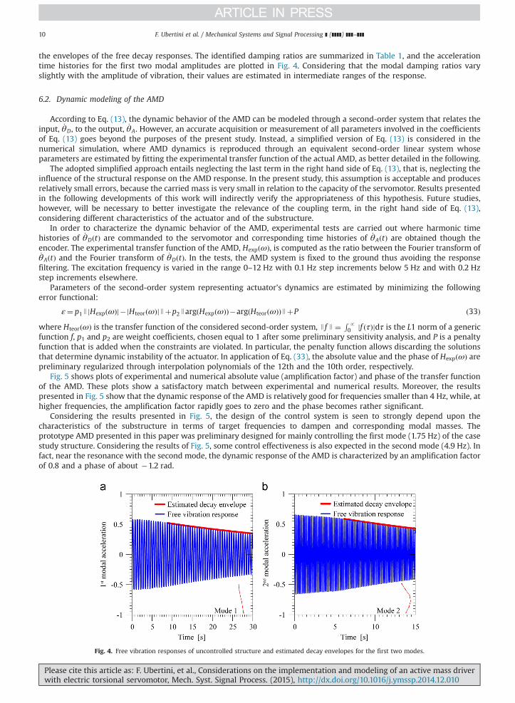
the envelopes of the free decay responses. The identified damping ratios are summarized in Table 1, and the accelerationtime histories for the first two modal amplitudes are plotted in Fig. 4. Considering that the modal damping ratios varyslightly with the amplitude of vibration, their values are estimated in intermediate ranges of the response.
6.2. Dynamic modeling of the AMD
According to Eq. (13), the dynamic behavior of the AMD can be modeled through a second-order system that relates theinput, _θD, to the output, _θA. However, an accurate acquisition or measurement of all parameters involved in the coefficientsof Eq. (13) goes beyond the purposes of the present study. Instead, a simplified version of Eq. (13) is considered in thenumerical simulation, where AMD dynamics is reproduced through an equivalent second-order linear system whoseparameters are estimated by fitting the experimental transfer function of the actual AMD, as better detailed in the following.
The adopted simplified approach entails neglecting the last term in the right hand side of Eq. (13), that is, neglecting theinfluence of the structural response on the AMD response. In the present study, this assumption is acceptable and producesrelatively small errors, because the carried mass is very small in relation to the capacity of the servomotor. Results presentedin the following developments of this work will indirectly verify the appropriateness of this hypothesis. Future studies,however, will be necessary to better investigate the relevance of the coupling term, in the right hand side of Eq. (13),considering different characteristics of the actuator and of the substructure.
In order to characterize the dynamic behavior of the AMD, experimental tests are carried out where harmonic timehistories of _θDðtÞ are commanded to the servomotor and corresponding time histories of _θAðtÞ are obtained though theencoder. The experimental transfer function of the AMD, HexpðωÞ, is computed as the ratio between the Fourier transform of_θAðtÞ and the Fourier transform of _θDðtÞ. In the tests, the AMD system is fixed to the ground thus avoiding the responsefiltering. The excitation frequency is varied in the range 0–12 Hz with 0.1 Hz step increments below 5 Hz and with 0.2 Hzstep increments elsewhere.
Parameters of the second-order system representing actuator's dynamics are estimated by minimizing the followingerror functional:
ε¼ p1 J jHexpðωÞj�jHteorðωÞjJþp2 JargðHexpðωÞÞ�argðHteorðωÞÞJþP ð33Þwhere HteorðωÞ is the transfer function of the considered second-order system, J f J ¼ R p
0 jf ðτÞjdτ is the L1 norm of a genericfunction f, p1 and p2 are weight coefficients, chosen equal to 1 after some preliminary sensitivity analysis, and P is a penaltyfunction that is added when the constraints are violated. In particular, the penalty function allows discarding the solutionsthat determine dynamic instability of the actuator. In application of Eq. (33), the absolute value and the phase of HexpðωÞ arepreliminary regularized through interpolation polynomials of the 12th and the 10th order, respectively.
Fig. 5 shows plots of experimental and numerical absolute value (amplification factor) and phase of the transfer functionof the AMD. These plots show a satisfactory match between experimental and numerical results. Moreover, the resultspresented in Fig. 5 show that the dynamic response of the AMD is relatively good for frequencies smaller than 4 Hz, while, athigher frequencies, the amplification factor rapidly goes to zero and the phase becomes rather significant.
Considering the results presented in Fig. 5, the design of the control system is seen to strongly depend upon thecharacteristics of the substructure in terms of target frequencies to dampen and corresponding modal masses. Theprototype AMD presented in this paper was preliminary designed for mainly controlling the first mode (1.75 Hz) of the casestudy structure. Considering the results of Fig. 5, some control effectiveness is also expected in the second mode (4.9 Hz). Infact, near the resonance with the second mode, the dynamic response of the AMD is characterized by an amplification factorof 0.8 and a phase of about �1.2 rad.
Fig. 4. Free vibration responses of uncontrolled structure and estimated decay envelopes for the first two modes.
Please cite this article as: F. Ubertini, et al., Considerations on the implementation and modeling of an active mass driverwith electric torsional servomotor, Mech. Syst. Signal Process. (2015), http://dx.doi.org/10.1016/j.ymssp.2014.12.010i

Fig. 5. Experimental and fitted numerical transfer function of the AMD: absolute value of transfer function (a); and phase of transfer function (b).
F. Ubertini et al. / Mechanical Systems and Signal Processing ] (]]]]) ]]]–]]] 11
7. Closed-loop system stability
The simplified numerical model presented in Section 6 is employed in order to investigate closed-loop stability of thecontrolled system. In Fig. 6(a) the root-locus of the system is plotted for values of the gain, G, increasing from 0 to 1000. Thecorresponding root locus of the system without considering the dynamics of the AMD is also shown in Fig. 6(a).
The results of Fig. 6(a) show that the root locus of the system is substantially affected by the dynamic characteristics ofthe AMD. In particular, the following remarks should be made: (i) if the dynamics of the AMD is neglected, the five structuralmodes are unconditionally stable and the corresponding poles depart from the imaginary axis because of the increase indamping; (ii) if the dynamics of the AMD is considered, the third mode shows an unstable behavior for G higher than about500; and (iii) as expected, at relatively low gains, the increase of the modal damping due to the control action is significant,especially for the first mode.
It is worth noting that the instability of the system at high gains is also verified by performing experimental tests. As anexample, Fig. 6(b) shows a sample time history of unstable response obtained for G¼700.
The presented results confirm that, as theoretically discussed in Section 4.3, an inherently stable collocated controller,such as the adopted skyhook controller, can result in closed-loop system instability as a consequence of actuator's dynamicsand CSI.
Another potentially destabilizing issue in practical applications is represented by time delay. In fact, imperfect delayedactuation of the AMD is conceptually similar to time delay effects. In order to gain more insight on this aspect, Fig. 7 shows aplot of stable and unstable domains numerically obtained for the considered system assuming an ideal actuator with timedelay Δt. The analysis is carried out in the range Δt ¼ 0�0:1 s. It is noted that the first instability is observed atΔt ¼ 27:5 ms, which is a quite larger value compared to the computational delay of 5 ms considered in the experiments.
In practical applications, time delay should be kept as small as possible not only to avoid instability but also in order toavoid deterioration of the control performance. To this regards, the use of a real time structural controller and a high speedcommunication protocol between structural controller and servomotor drive, are crucial towards limiting the time delaybelow a few milliseconds.
8. Experimental and numerical controlled responses
8.1. Free vibration tests
After the preliminary experimental tests presented in Sections 6 and 7, a campaign of experimental tests is carried out inorder to investigate the effectiveness of the control system and to compare experimental results with numerical predictions.The gain of the control system is set equal to 180. This value guarantees a significant control effectiveness and avoidsexceeding the stroke limit of the AMD at low frequencies.
Free vibration tests are performed, at first, as follows: after blocking the sliding base table, the frame is excited using theAMD as an harmonic shaker, which is then switched to control, after a few seconds in stop position. Frequencies ofexcitation close to the natural frequencies of the system are used.
Fig. 8 shows the free vibration responses obtained after exciting the structure at frequencies of 1.8 Hz (Fig. 8(a)), close tothe first modal frequency, and 5 Hz (Fig. 8(b)), close to the second modal frequency. It can be observed that, as expected, thecontrol system is effective in reducing the structural response, especially for the first mode. For the reasons explained inSection 6.2, related to the dynamic characteristics of the AMD, the system is less effective in reducing the structuralresponse, when this is dominated by the second mode.
Please cite this article as: F. Ubertini, et al., Considerations on the implementation and modeling of an active mass driverwith electric torsional servomotor, Mech. Syst. Signal Process. (2015), http://dx.doi.org/10.1016/j.ymssp.2014.12.010i
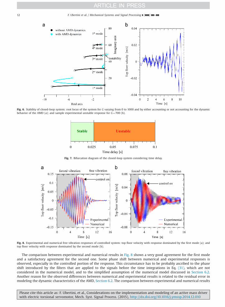
Fig. 6. Stability of closed-loop system: root locus of the system for G varying from 0 to 1000 and by either accounting or not accounting for the dynamicbehavior of the AMD (a); and sample experimental unstable response for G¼700 (b).
Fig. 7. Bifurcation diagram of the closed-loop system considering time delay.
Fig. 8. Experimental and numerical free vibration responses of controlled system: top floor velocity with response dominated by the first mode (a); andtop floor velocity with response dominated by the second mode (b).
F. Ubertini et al. / Mechanical Systems and Signal Processing ] (]]]]) ]]]–]]]12
The comparison between experimental and numerical results in Fig. 8 shows a very good agreement for the first modeand a satisfactory agreement for the second one. Some phase shift between numerical and experimental responses isobserved, especially in the controlled portion of the response. This circumstance has to be probably ascribed to the phaseshift introduced by the filters that are applied to the signals before the time integrations in Eq. (31), which are notconsidered in the numerical model, and to the simplified assumption of the numerical model discussed in Section 6.2.Another reason for the observed differences between numerical and experimental results is related to the residual error inmodeling the dynamic characteristics of the AMD, Section 6.2. The comparison between experimental and numerical results
Please cite this article as: F. Ubertini, et al., Considerations on the implementation and modeling of an active mass driverwith electric torsional servomotor, Mech. Syst. Signal Process. (2015), http://dx.doi.org/10.1016/j.ymssp.2014.12.010i

F. Ubertini et al. / Mechanical Systems and Signal Processing ] (]]]]) ]]]–]]] 13
for the second mode, Fig. 8(b), outlines that the numerical model underestimates the control effectiveness at largeamplitudes of the response while, conversely, the experimental response shows a residual tail that is essentially not dampenout. This aspect is probably related to the circumstance that the motor is inactive until the demand value of the velocity doesnot overcome a certain threshold (velocity activation levels of the motor). Although experimental and numerical responsesare not perfectly overlapped, their agreement is good and the obtained results allow to conclude that the expected controleffectiveness of the AMD, in free vibration, is confirmed.
8.2. Harmonically forced vibration tests
Forced vibration tests consist in the application of sinusoidal excitation to the shaking table. The frequency of theharmonic input is increased from 1 to 6 Hz with step increments of 0.1 Hz. Tests are carried out for both uncontrolled andcontrolled structure, with G¼180. Fig. 9(a) shows the results in terms of amplification factor between relative top-baseresponse and base excitation. The amplification factor is obtained as the absolute value of the top-base transfer function ofthe controlled structure. Fig. 9(b) and (c) shows window plots of sample time histories of numerical and experimentalcontrolled responses at excitation frequencies of 1.8 Hz and 5.0 Hz, respectively.
The results presented in Fig. 9 confirm that the control system is highly effective in reducing the structural response inthe region of the first modal resonance, while it is less effective in reducing the response in the region of the second modalresonance. The agreement between experimental and numerical results is good in the region of the first modal resonance,although the peak responses observed in the experiments and in the numerical simulations are slightly mistuned, one withrespect to the other. As also evidenced in Section 8.1 and for the same reasons discussed there, the differences betweenexperimental and numerical responses are comparatively more significant in the region of the resonance with the secondmode. However, also in the case of the forced vibration tests, it can be concluded that experimental results well agree withnumerical results and the expected control effectiveness of the system is confirmed in the whole investigatedfrequency range.
Fig. 9(a) also shows the numerical top-base amplification factor obtained by neglecting the dynamics of the actuator. Inthe region of the first modal resonance, this curve is almost overlapped to that obtained by accounting for the dynamics ofthe AMD, which confirms that the actuator is well-designed for damping the vibrations of the first mode. On the contrary,the effects of the dynamic behavior of the AMD are more significant near the resonance with the second mode. In fact, inthis region, the experimental response appears to be intermediate between the numerical responses obtained with andwithout AMD dynamics.
8.3. Numerical verification of control effectiveness under seismic excitation
A verification of the AMD effectiveness under seismic excitation is carried out. Because the adopted electrodynamicshaker providing base excitation operates in open-loop conditions and has a limited stroke extension (2 cm from peak topeak), it is inadequate to reproduce actual seismic excitation signals. Therefore, the analysis under seismic excitation is
Fig. 9. Experimental and numerical responses in harmonically forced vibration tests: absolute value of top-base transfer function (a); window time historyplots of experimental and numerical controlled responses at excitation frequencies of 1.8 Hz (b) and 5.0 Hz (c).
Please cite this article as: F. Ubertini, et al., Considerations on the implementation and modeling of an active mass driverwith electric torsional servomotor, Mech. Syst. Signal Process. (2015), http://dx.doi.org/10.1016/j.ymssp.2014.12.010i

F. Ubertini et al. / Mechanical Systems and Signal Processing ] (]]]]) ]]]–]]]14
carried using the simplified numerical model presented in Section 6. Three different seismic records are considered for thispurpose (El Centro, Friuli and Kokaeli). The controlled response is computed numerically with both the classic linearquadratic regulator (LQR) and the skyhook control laws. As it is common in the literature (e.g. [37,38]), the performances of
Table 3Performance indices for different seismic records.
Earthquake record J1 ð%Þ J2 ð%Þ J3 ð%Þ J4 ð%Þ J5 ð%Þ J6 ð%Þ J7 ð%Þ J8 ð%Þ J9 ð%Þ
El Centro 44.1 33.8 12.3 84.9 39.5 86.1 100.0 109.8 139.6Friuli 30.3 33.9 21.2 103.0 37.2 98.3 100.0 97.4 104.7Kokaeli 40.7 51.5 18.9 96.3 55.3 90.9 100.0 95.4 120.2
Fig. 10. Seismic records (a–c) and corresponding top floor displacement (d–f) obtained for the uncontrolled and the controlled systems.
Please cite this article as: F. Ubertini, et al., Considerations on the implementation and modeling of an active mass driverwith electric torsional servomotor, Mech. Syst. Signal Process. (2015), http://dx.doi.org/10.1016/j.ymssp.2014.12.010i
F. Ubertini et al. / Mechanical Systems and Signal Processing ] (]]]]) ]]]–]]] 15
the different control systems are compared in terms of nine scalar indices J1; J2;…; J9, defined as follows:
J1 %ð Þ ¼ maxt jqnðtÞjskymaxt jqnðtÞjunc
J2 %ð Þ ¼ maxt j €qnðtÞjskymaxt j €qnðtÞjunc
J3 %ð Þ ¼ σskyqn
σuncqn
J4 %ð Þ ¼maxt jqnðtÞjskymaxt jqnðtÞjlqr
J5 %ð Þ ¼maxt j €qnðtÞjskymaxt j €qnðtÞjlqr
J6 %ð Þ ¼ σskyqn
σlqrqn
J7 %ð Þ ¼maxt juðtÞjskymaxt juðtÞjlqr
J8 %ð Þ ¼ σskyu
σlqru
J9 %ð Þ ¼maxt jqaðtÞ�qnðtÞjskymaxt jqaðtÞ�qnðtÞjlqr
ð34Þ
where the subscript “sky” refers to the skyhook control, “lqr” to the LQR control and “unc” to the uncontrolled case, while σisthe root mean square operator. For comparative purposes, the gains of the two control strategies are tuned in order to haveequal peak control forces, that is, J7ð%Þ ¼ 100. The results are summarized in Table 3 and Fig. 10. In particular, Fig. 10(a–c)shows the acceleration records used for the analyses, while Fig. 10(d–f) presents the corresponding top floor displacements ofthe uncontrolled and controlled structures. In the same figures, the responses obtained with both the considered controlstrategies are compared. The results demonstrate that the AMD can significantly reduce structural displacements in a way thatis essentially weakly affected by the chosen control algorithm. On the contrary, the skyhook control algorithm seems to besuperior compared to the LQR in reducing structural accelerations, at the expense of larger stroke requirements for themovable mass.
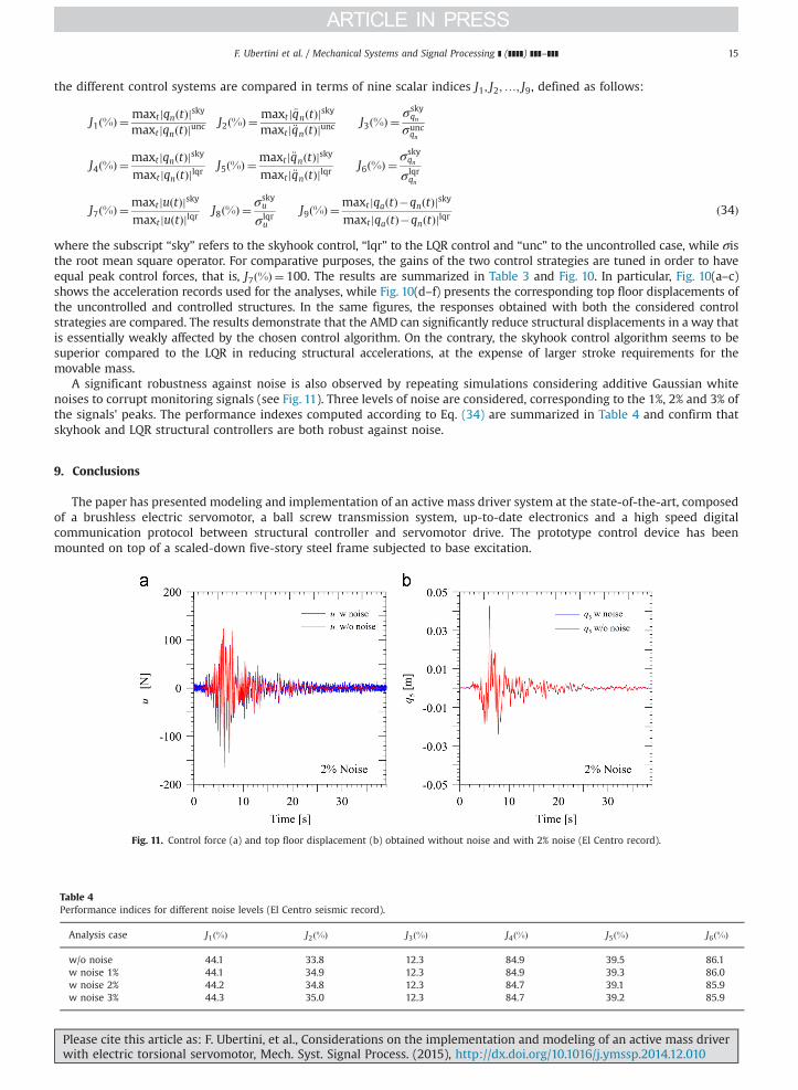
A significant robustness against noise is also observed by repeating simulations considering additive Gaussian whitenoises to corrupt monitoring signals (see Fig. 11). Three levels of noise are considered, corresponding to the 1%, 2% and 3% ofthe signals' peaks. The performance indexes computed according to Eq. (34) are summarized in Table 4 and confirm thatskyhook and LQR structural controllers are both robust against noise.
9. Conclusions
The paper has presented modeling and implementation of an active mass driver system at the state-of-the-art, composedof a brushless electric servomotor, a ball screw transmission system, up-to-date electronics and a high speed digitalcommunication protocol between structural controller and servomotor drive. The prototype control device has beenmounted on top of a scaled-down five-story steel frame subjected to base excitation.
Fig. 11. Control force (a) and top floor displacement (b) obtained without noise and with 2% noise (El Centro record).
Table 4Performance indices for different noise levels (El Centro seismic record).
Analysis case J1ð%Þ J2ð%Þ J3ð%Þ J4ð%Þ J5ð%Þ J6ð%Þ
w/o noise 44.1 33.8 12.3 84.9 39.5 86.1w noise 1% 44.1 34.9 12.3 84.9 39.3 86.0w noise 2% 44.2 34.8 12.3 84.7 39.1 85.9w noise 3% 44.3 35.0 12.3 84.7 39.2 85.9
Please cite this article as: F. Ubertini, et al., Considerations on the implementation and modeling of an active mass driverwith electric torsional servomotor, Mech. Syst. Signal Process. (2015), http://dx.doi.org/10.1016/j.ymssp.2014.12.010i

F. Ubertini et al. / Mechanical Systems and Signal Processing ] (]]]]) ]]]–]]]16
The mathematical setting has been established, at first, by extending the equations of motion available in the literature tothe case of a servomotor regulated in a kinematic way, that is, by assigning its setpoint angular velocity and not its torque. Aspecial feature of the derived equations of motion is fully including CSI, considered for the first time in the case of an AMDwith torsional servomotor. The developed analytical model has allowed to (i) clarify the nature of the double loopinteraction existing between actuator and structure, (ii) discuss the role played by different characteristics and properties ofthe actuator on the system dynamics, and (iii) highlight design constraints of the control system.
The performance of the control system has been tested considering an inherently stable collocated skyhook controlalgorithm, under free and harmonically forced vibrations. Measured responses have been compared with numericalpredictions for results interpretation. Numerical simulations have been carried out by means of a simplified tunedmathematical model of the system, preliminary identified through a model updating considering identified structural modalparameters and measured transfer function of the active mass driver.
The results have allowed to verify the control effectiveness of the active mass driver system and have also outlined thecentral role played by the dynamic behavior of the actuator. Imperfect dynamic actuation, essentially influenced by theinertia of the screw and of the movable mass, has been found responsible for a loss of closed-loop system stability at highgains, similarly to time delay effects, and for a loss of control effectiveness in the higher order modes, as verified boththeoretically and experimentally.
Numerical simulations have also allowed to verify the efficacy of the active mass driver in the case of seismic excitationand have highlighted the secondary role played by the control algorithm in determining such a control effectiveness, at leastin terms of structural displacements. More important, in the perspective of applying the AMD in seismic structuralprotection, seem to be the issues related to proper modeling of actuator's dynamics and its double loop interaction with thestructure.
Acknowledgments
The authors gratefully acknowledge the financial support of the “Cassa di Risparmio di Perugia” Foundation that fundedthis study through the Project “Development of active control systems for the response mitigation under seismic excitation”(Grant number 2010.011.0490).
Suggestions and comments by Professor Gianluca Rossi, Dr. Michele Moretti and Dr. Matteo Becchetti, University ofPerugia, are also acknowledged with gratitude. The authors also wish to thank Mr. Riccardo Susini, National Instruments,and Mr. Mike Taurasi, Taurasi Engineering SRL, for their contribution to the development of the physical model.
References
[1] F. Cluni, V. Gusella, S. Spence, G. Bartoli, Wind action on regular and irregular tall buildings: higher order moment statistical analysis by HFFB andSMPSS measurements, J. Wind Eng. Ind. Aerodyn. 99 (2011) 682–690.
[2] B. Spencer, S. Nagarajah, State of the art of structural control, J. Struct. Eng. 129 (2003) 845–856.[3] E. Renzi, G. Serino, Testing and modelling a semi-actively controlled steel frame structure equipped with MR dampers, Struct. Control Health Monit. 11
(2004) 189–221.[4] S. Krenk, J. Hogsberg, Optimal resonant control of flexible structures, J. Sound Vib. 323 (2009) 530–554.[5] C. Li, M. Liang, Characterization and modeling of a novel electro-hydraulic variable two-terminal mass device, Smart Mater. Struct. 21 (2012) 025004.[6] X. Shao, A. Reinhorn, M. Sivaselvan, Real-time hybrid simulation using shake tables and dynamic actuators, J. Struct. Eng. 137 (2011) 748–760.[7] T. Soong, Active Structural Control – Theory and Practice, Longman Scientific & Technical, Essex, England, 1990.[8] Y. Fujino, Vibration, control and monitoring of long-span bridges-recent research, developments and practice in Japan, J. Constr. Steel Res. 58 (2002)
71–97.[9] I. Venanzi, A. Materazzi, Acrosswind aeroelastic response of square tall buildings: a semi-analytical approach based of wind tunnel tests on rigid
models, Wind Struct. 15 (2012) 495–508.[10] G. Pujol, L. Acho, F. Pozo, A. Rodríguez, Y. Vidal, A velocity based active vibration control of hysteretic systems, Mech. Syst. Signal Process. 25 (2011)
465–474.[11] Q. Zhi-cheng, Adaptive nonlinear vibration control of a cartesian flexible manipulator driven by a ballscrew mechanism, Mech. Syst. Signal Process. 30
(2012) 248–266.[12] Y. Ikeda, Active and semi-active vibration control of buildings in Japan—Practical applications and verification, Struct. Control Health Monit. 16 (2009)
703–723.[13] S. Dyke, B. Spencer Jr., P. Quast, M. Sain, Role of control-structure interaction in protective system design, J. Eng. Mech. 121 (1995) 322–338.[14] C. Zhang, J. Ou, Control structure interaction of electromagnetic mass damper system for structural vibration control, J. Eng. Mech. 134 (2008) 428–437.[15] A. Pirrotta, M. Zingales, Active controlled structural systems under delta-correlated random excitation: linear and nonlinear case, Commun. Nonlinear
Sci. Numer. Simul. 11 (2006) 646–661.[16] S. Casciati, Z. Chen, An active mass damper system for structural control using real-time wireless sensors, Struct. Control Health Monit. 19 (2012)
758–767.[17] S. Chen, M. Song, Y. Chen, Robustness analysis of responses of vibration control structures with uncertain parameters using interval algorithm, Struct.
Saf. 29 (2007) 94–111.[18] M. Battaini, F. Casciati, L. Faravelli, Some reliability aspects in structural control, Probab. Eng. Mech. 15 (2000) 101–107.[19] Y. Halevi, C. Wagner-Nachshoni, Transfer function modeling of multi-link flexible structures, J. Sound Vib. 296 (2006) 73–90.[20] I. Peled, W. O'Connor, Y. Halevi, On the relationship between wave based control, absolute vibration suppression and input shaping, Mech. Syst. Signal
Process. 39 (2012) 80–90.[21] A. Materazzi, F. Ubertini, Robust structural control with system constraints, Struct. Control Health Monit. 19 (2012) 472–490.[22] I. Venanzi, F. Ubertini, Free vibration response of a frame structural model controlled by a nonlinear active mass driver system, Adv. Civil Eng. ID
745814 (2014).
Please cite this article as: F. Ubertini, et al., Considerations on the implementation and modeling of an active mass driverwith electric torsional servomotor, Mech. Syst. Signal Process. (2015), http://dx.doi.org/10.1016/j.ymssp.2014.12.010i

F. Ubertini et al. / Mechanical Systems and Signal Processing ] (]]]]) ]]]–]]] 17
[23] I. Venanzi, F. Ubertini, A. Materazzi, Optimal design of an array of active tuned mass dampers for wind-exposed high-rise buildings, Struct. ControlHealth Monit. 20 (2013) 903–917.
[24] S. Dyke, B. Spencer, P. Quast, D. Kaspari Jr., M. Sain, Implementation of an active mass driver using acceleration feedback control, Microcomput. CivilEng. 11 (1996) 305–323.
[25] A. Forrai, S. Hashimoto, A. Isojima, H. Funato, K. Kamiyama, Gray box identification of flexible structures: application to robust active vibrationsuppression control, Earthq. Eng. Struct. Dyn. 30 (2001) 1203–1220.
[26] C. Moutinho, A. Cunha, E. Caetano, Implementation of an active mass driver for increasing damping ratios of the laboratorial model of a building,J. Theor. Appl. Mech. 49 (2011) 791–806.
[27] O. Huajiang, A hybrid control approach for pole assignment to second-order asymmetric systems, Mech. Syst. Signal Process. 25 (2011) 123–132.[28] S. Chu, T. Soong, A. Reinhorn, Active, Hybrid and Semi-Active Structural Control, John Wiley and Sons, Ltd, England, 2005.[29] C. Lee, Y. Wang, Seismic structural control using an electric servomotor active mass driver system, Earthq. Eng. Struct. Dyn. 33 (2004) 737–754.[30] J. Connor, S. Laflamme, Structural Motion Engineering, Springer International Publishing, Switzerland, 2014.[31] Y. Nakamura, K. Tanaka, M. Nakayama, T. Fujita, Hybrid mass dampers using two types of electric servomotors: AC servomotors and linear-induction
servomotors, Earthq. Eng. Struct. Dyn. 30 (2001) 1719–1743.[32] T. Saito, K. Shiba, K. Tamura, Vibration control characteristics of a hybrid mass damper system installed in tall buildings, Earthq. Eng. Struct. Dyn. 30
(2001) 1677–1696.[33] C.W. Zhang, J.P. Ou, Modeling and dynamical performance of the electromagnetic mass driver system for structural vibration control, Eng. Struct. 82
(2015) 93–103.[34] H.B. Xu, C.W. Zhang, H. Li, J.P. Ou, Real-time hybrid simulation approach for performance validation of structural active control systems: a linear motor
actuator based active mass driver case study, Struct. Control Health Monit. 21 (2014) 574–589.[35] H.B. Xu, C.W. Zhang, H. Li, P. Tan, J.P. Ou, F.L. Zhou, Active mass driver control system for suppressing wind-induced vibration of the canton tower,
Smart Struct. Syst. 13 (2014) 281–303.[36] M. Yamamoto, T. Sone, Behavior of active mass damper (AMD) installed in high-rise building during 2011 earthquake off pacific coast of Tohoku and
verification of regenerating system of AMD based on monitoring, Struct. Control Health Monit. 21 (2014) 634–647.[37] C.W. Zhang, J.P. Ou, Shaking table tests of electromagnetic mass damper system for control of structural seismic response, J. Earthq. Eng. Eng. Vib. 26
(2006) 104–110.[38] C.W. Zhang, J.P. Ou, Control strategies and experimental verifications of the electromagnetic mass damper system for structural vibration control,
Earthq. Eng. Eng. Vib. 7 (2008) 181–192.
Please cite this article as: F. Ubertini, et al., Considerations on the implementation and modeling of an active mass driverwith electric torsional servomotor, Mech. Syst. Signal Process. (2015), http://dx.doi.org/10.1016/j.ymssp.2014.12.010i
Related Documents