x alliedtelesis.com C613-22103-00 REV A Feature Overview and Configuration Guide Technical Guide Introduction This guide describes Connectivity Fault Management (CFM) and how to configure it. For many years, Network Service Providers (NSPs) have managed their networks using the FCAPS model: Fault, Configuration, Accounting, Performance, and Security. CFM is an IEEE 802.1ag and ITU Y.1731 standard for managing connectivity at the Ethernet service level. The 802.1ag standard adds Fault management capabilities to Ethernet, while the ITU Y.1731 standard expands the capabilities to include Performance. Table 1-1: 802.1ag and Y.1731 Capabilities CATEGORY FUNCTION NOTES STANDARD Fault Management Fault Detection. Continuity Checks (CC) are performed using Continuity Check Messages (CCM). One-way heartbeat using Multicast or Unicast. 802.1ag, Y.1731 Fault Verification. Faults are verified using Loopbacks which is a MAC address based "ping" using LoopBack Messages and Replies (LBM/LBR). 802.1ag: Sends unicast request, gets unicast response. Y.1731: also supports multicast request to all and expects unicast replies from all. 802.1ag, Y.1731 Fault Isolation. Faults are isolated to a particular location using Link Trace which is a MAC address based “link trace” using LinkTrace Messages and Replies (LTM/LTR). Multicast Requests, Unicast Response hop-by-hop. 802.1ag, Y.1731 Alarm Indication Signal (AIS)/Remote Defect Indicator (RDI) for fault propagation and Alarm Suppression. AIS is a message. RDI is a bit in CCM. Y.1731 Performance Management Loss Measurements using Loss Measurement Messages and Response (LMM, LMR). Measures Service Frame counts for loss Y.1731 Delay Measurements either 1-way or 2-way using Delay Measurement Messages and Response (DMM,DMR). Measures Service Frame Delays. Can also use (LBM,LBR) for 2-way delay. Y.1731 Connectivity Fault Management

Welcome message from author
This document is posted to help you gain knowledge. Please leave a comment to let me know what you think about it! Share it to your friends and learn new things together.
Transcript
Feature Overview and Configuration Guide
Technical Guide
Connectivity Fault Management
Introduction
This guide describes Connectivity Fault Management (CFM) and how to configure it.
For many years, Network Service Providers (NSPs) have managed their networks using
the FCAPS model: Fault, Configuration, Accounting, Performance, and Security. CFM is
an IEEE 802.1ag and ITU Y.1731 standard for managing connectivity at the Ethernet
service level. The 802.1ag standard adds Fault management capabilities to Ethernet,
while the ITU Y.1731 standard expands the capabilities to include Performance.
Table 1-1: 802.1ag and Y.1731 Capabilities
CATEGORY FUNCTION NOTES STANDARD
Fault Management
Fault Detection. Continuity Checks (CC) are performed using Continuity Check Messages (CCM).
One-way heartbeat using Multicast or Unicast.
802.1ag, Y.1731
Fault Verification. Faults are verified using Loopbacks which is a MAC address based "ping" using LoopBack Messages and Replies (LBM/LBR).
802.1ag: Sends unicast request, gets unicast response.Y.1731: also supports multicast request to all and expects unicast replies from all.
802.1ag, Y.1731
Fault Isolation. Faults are isolated to a particular location using Link Trace which is a MAC address based “link trace” using LinkTrace Messages and Replies (LTM/LTR).
Multicast Requests, Unicast Response hop-by-hop.
802.1ag, Y.1731
Alarm Indication Signal (AIS)/Remote Defect Indicator (RDI) for fault propagation and Alarm Suppression.
AIS is a message. RDI is a bit in CCM.
Y.1731
Performance Management
Loss Measurements using Loss Measurement Messages and Response (LMM, LMR).
Measures Service Frame counts for loss
Y.1731
Delay Measurements either 1-way or 2-way using Delay Measurement Messages and Response (DMM,DMR).
Measures Service Frame Delays. Can also use (LBM,LBR) for 2-way delay.
Y.1731
x alliedtelesis.comC613-22103-00 REV A
Connectivity Fault Management
ContentsIntroduction ........................................................................................................................ 1
Products and software version that apply to this guide .............................................. 3
Overview of Connectivity Fault Management .................................................................... 4
Link level versus VLAN level CFM ............................................................................... 4
Link level .............................................................................................................. 4
VLAN level ............................................................................................................ 4
CFM management model ............................................................................................ 5
Maintenance Domain (MD)................................................................................... 5
Maintenance Association (MA)............................................................................. 6
Maintenance Entity Group (MEG)......................................................................... 6
Maintenance Point (MP)............................................................................................... 6
Maintenance End Point (MEP) ............................................................................. 6
Maintenance Intermediate Point (MIP) ................................................................. 6
Up......................................................................................................................... 6
Down .................................................................................................................... 6
CFM example network................................................................................................. 8
CFM diagram explanation.................................................................................... 9
How CFM Works .............................................................................................................. 13
Continuity check........................................................................................................ 13
Continuity check message ........................................................................................ 14
Connectivity defects .................................................................................................. 16
Local defects...................................................................................................... 16
Remote defects.................................................................................................. 17
Connectivity alarms ................................................................................................... 17
How to Use this Feature................................................................................................... 18
CFM configuration ..................................................................................................... 18
Enable CFM........................................................................................................ 18
Configure the MD ............................................................................................... 18
Configure the MA ............................................................................................... 19
Configure local MEPs......................................................................................... 21
Configure remote MEPs ..................................................................................... 22
CCM configuration..................................................................................................... 23
MA CCM - Continuity Check (CC) Interval......................................................... 23
Local MEP CCM - Enable CCM......................................................................... 23
Local MEP CCM - Connectivity alarms.............................................................. 24
Configuration Examples ................................................................................................... 26
Show Commands............................................................................................................. 29
Page 2 |
Connectivity Fault Management
Maintenance domain ..................................................................................................29
Configuration ......................................................................................................29
Connectivity status (MD view) - event list ...........................................................30
Maintenance association............................................................................................31
Local MEPs.................................................................................................................32
Counters .............................................................................................................36
Alarms .................................................................................................................36
Remote MEP ..............................................................................................................37
Show all details...........................................................................................................38
Products and software version that apply to this guide
This guide applies to AlliedWare Plus™ products that support CFM, running version 5.4.7-
1 or later.
A CFM feature license may be required to use the features in this guide. To see whether
your product supports CFM, and for details of any licensing required, see the following
documents:
The product’s Datasheet
The product’s Command Reference
These documents are available from the above links on our website at alliedtelesis.com.
Feature support may change in later software versions. For the latest information, see the
above documents.
Note: Only 802.1ag Fault Detection is supported in this version of AlliedWare Plus.
Products and software version that apply to this guide | Page 3
Connectivity Fault Management
Overview of Connectivity Fault Management
Link level versus VLAN level CFM
Ethernet CFM provides the network operator with a way to detect faults in the network,
and to isolate the location of the fault at either the link level (i.e. port) or at the VLAN level.
Y.1731 extends this, and also provides a way to manage Service Level Agreements (SLAs)
at the link level, but more importantly at the VLAN level.
Link level
Standard 802.3 link technology such as 1000BASE-T or 1000BASE-X provides fault
detection through normal Link Up and Link Down mechanisms. These mechanisms are
not always sufficient; for example, they may not detect a Link Down if only one direction
fails. Another example is when media converters are used and a failure occurs on one side
of the media converter, but the other side of the media converter remains Link Up. The
Ethernet station, bridge, or router on the non-failing side of the media converter sees the
link as Up and does not realize that it can no longer talk to its peer on the failing side of
the media converter.
CFM uses Continuity Check Messages (CCMs) that are carried over a link path in both
directions. This allows the two ends of a link to detect a variety of fault scenarios,
overcoming the limitations of standard 802.3 link technology.
VLAN level
A VLAN may provide simple point-to-point connectivity between two entities across a
Layer 2 network, or multipoint-to-multipoint connectivity between several entities.
Ethernet CFM can detect faults in either case by monitoring CCMs that are being sent
from all the entities (bridges, routers, and stations) that use the VLAN. If one entity can no
longer be heard from by another entity then a fault is declared. Y.1731 provides a way to
manage SLAs in a similar fashion, but does so primarily on point-to-point VLANs.
Page 4 | Link level versus VLAN level CFM
Connectivity Fault Management
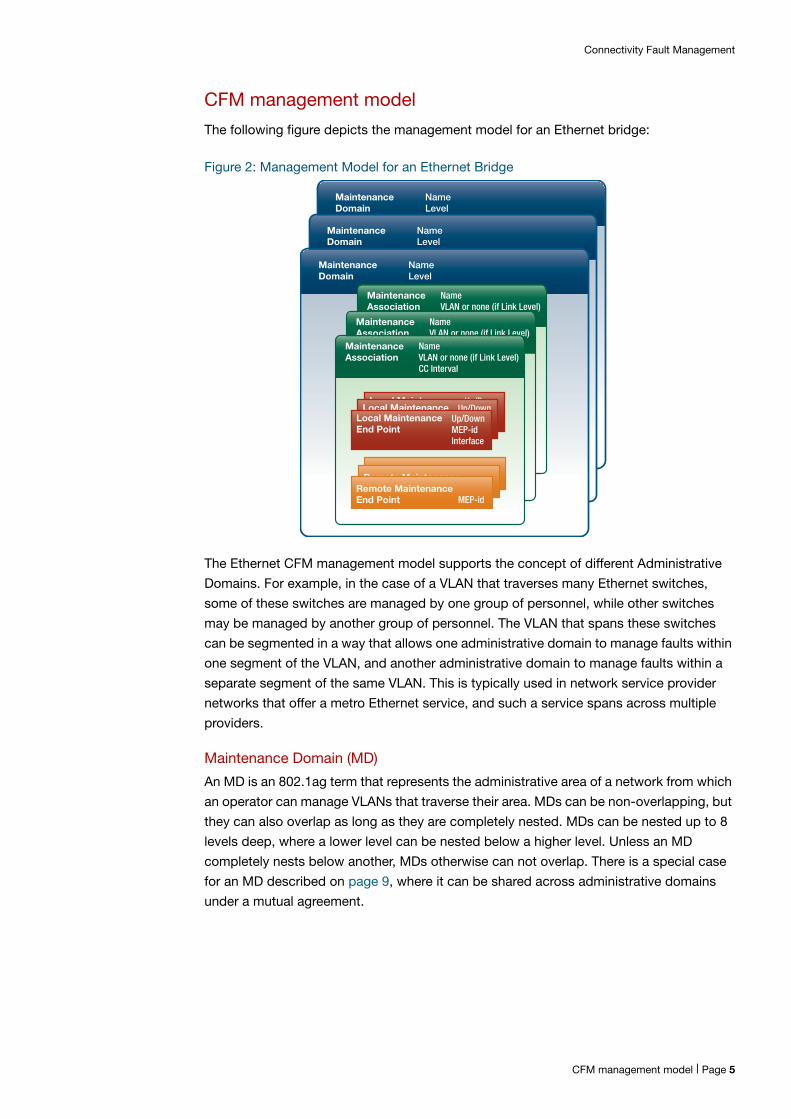
CFM management model
The following figure depicts the management model for an Ethernet bridge:
Figure 2: Management Model for an Ethernet Bridge
The Ethernet CFM management model supports the concept of different Administrative
Domains. For example, in the case of a VLAN that traverses many Ethernet switches,
some of these switches are managed by one group of personnel, while other switches
may be managed by another group of personnel. The VLAN that spans these switches
can be segmented in a way that allows one administrative domain to manage faults within
one segment of the VLAN, and another administrative domain to manage faults within a
separate segment of the same VLAN. This is typically used in network service provider
networks that offer a metro Ethernet service, and such a service spans across multiple
providers.
Maintenance Domain (MD)
An MD is an 802.1ag term that represents the administrative area of a network from which
an operator can manage VLANs that traverse their area. MDs can be non-overlapping, but
they can also overlap as long as they are completely nested. MDs can be nested up to 8
levels deep, where a lower level can be nested below a higher level. Unless an MD
completely nests below another, MDs otherwise can not overlap. There is a special case
for an MD described on page 9, where it can be shared across administrative domains
under a mutual agreement.
Remote MaintenanceEndPoint MEP-id
MaintenanceDomain
NameLevel
MaintenanceDomain
NameLevel
MaintenanceDomain
NameLevel
MaintenanceAssociation
NameVLAN or none (if Link Level)CC IntervalMaintenance
AssociationNameVLAN or none (if Link Level)CC IntervalMaintenance
AssociationNameVLAN or none (if Link Level)CC Interval
Local MaintenanceEndPoint
Up/DownMEP-idInterface
Local MaintenanceEndPoint
Up/DownMEP-idInterface
Local MaintenanceEnd Point
Up/DownMEP-idInterface
Remote MaintenanceEndPoint MEP-idRemote Maintenance
EndPoint MEP-idRemote MaintenanceEnd Point MEP-id
CFM management model | Page 5
Connectivity Fault Management
Maintenance Association (MA)
An MA is an 802.1ag term that represents a particular VLAN within that administrative
domain. In other words, it is a segment of a VLAN that is managed. As a VLAN is often the
granularity that a network service provider sells to their customer, an MA is often referred
to as a Service. An MA can also represent a link. As such, an MA can be used at a link
level or a VLAN level.
Maintenance Entity Group (MEG)
An MEG is an ITU Y.1731 term. ITU does not differentiate between an MD and an MA and
considers them as one. An MEG is effectively the same as an 802.1ag MA with a Null MD.
Note: CCMs contain the name of the MD and/or the name of the MA in the message. If the CFM message is based on 802.1ag, it contains both MD and MA names. If the message is based on Y.1731, then it only contains the MEG ID. For interoperability between 802.1ag and Y.1731, the MD will need to be configured as Null.
Maintenance Point (MP)
MPs are entities that exist within an MD/MA and can perform the 802.1ag and Y.1731
functions for fault management and performance checks.
Maintenance End Point (MEP)
This type of MP sits at the edges of an MD but is a member of only one MA within the MD.
As such, an MEP is used at the end of a VLAN segment, or it is used at the end of a link.
Maintenance Intermediate Point (MIP)
This type of MP does not sit at the edges of an MD, but instead sits somewhere in
between the MEPs. MIPs are used primarily as reflection points for Layer 2 pings and
traceroutes, called Loop-Backs (LBM) and Link-Trace (LTM) respectively.
Note: MIPs, LBM, and LTM are not supported in this version of AlliedWare Plus.
MPs live on bridge ports and station ports. On a bridge port, there are two types:
Up
An Up Maintenance Entity is considered an inward MP. It communicates across the inside
of the bridge to the other side, and this allows it to reach the outside world. It lives on a
bridge port for a given VLAN, but it does not use this port to send or receive to get to the
outside world. Instead, it sends and receives through the inside of the bridge and
communicates to the outside world through the other VLAN port members. An Up MP
cannot be used for Link Level CFM.
Down
A Down Maintenance Entity is considered an outward MP. It sends and receives only
through its bridge port outwardly to the outside world, and does not communicate inside
the bridge. A Down MP is not subject to blocking due to Spanning Tree Protocol (STP) or
Page 6 | Maintenance Point (MP)
Connectivity Fault Management
any other protocol trying to prevent loops in the network. As such, it is important that
Down MPs be used in a MD/MA that is not subject to topology loops. A Down MP can be
VLAN aware or link-local.
An MEP can be either Up or Down for a given MD/MA, but within a bridge for the same
MD/MA, there can only be one Up or Down MEP (not both). An Up MEP must be VLAN
aware. A Down MEP may be VLAN aware. Otherwise, a Down MEP is allowed to be link-
local (VLAN unaware), and its scope is that of the entire link.
An MIP consists of two halves and always exists as a pair. One half is called an Up MIP
Half Function (MHF), the other half is called a Down MHF. It is always VLAN aware. MIPs
are restricted to only one on a bridge port and VLAN.
From a bridge management view point, a bridge is configured with the following:
an MD,
MAs (VLAN aware or link-local) that are associated with the MD,
local MEPs that are configured on a bridge port and are associated with an MA, and
for CCMs, a group of remote MEPs are configured that are also associated with the MA.
These remote MEPs are the ones from which the local MEPs expect to hear from
CCMs.
Maintenance Point (MP) | Page 7
Connectivity Fault Management
CFM example network
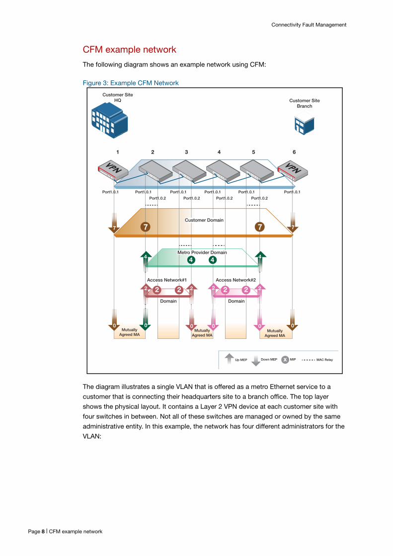
The following diagram shows an example network using CFM:
Figure 3: Example CFM Network
The diagram illustrates a single VLAN that is offered as a metro Ethernet service to a
customer that is connecting their headquarters site to a branch office. The top layer
shows the physical layout. It contains a Layer 2 VPN device at each customer site with
four switches in between. Not all of these switches are managed or owned by the same
administrative entity. In this example, the network has four different administrators for the
VLAN:
Customer SiteHQ Customer Site
Branch
7 7 7 7
0 0
0 0 00
MutuallyAgreed MA
Customer Domain
x
4 4
1 2 3 4 5 6
4 4
2 2 2 2
Port1.0.2 Port1.0.2 Port1.0.2 Port1.0.2
Port1.0.1Port1.0.1Port1.0.1Port1.0.1 Port1.0.1 Port1.0.1
2 22 2
Metro Provider Domain
Access Network#1 Access Network#2
Domain Domain
MutuallyAgreed MA
MutuallyAgreed MA
Up MEP Down MEP MIP MAC Relay
Page 8 | CFM example network
Connectivity Fault Management
1. Customer is the name of the customer buying the metro Ethernet service for connecting their two remote sites.
2. The Metro Provider is the network service provider that sells the metro Ethernet service to the end user.
3. Access Network #1 is the network service provider that provides the access to Customer at the headquarters site. This provider sells an Access Service to the Metro Provider, that in turn sells the access service to Customer at the headquarters site.
4. Access Network #2 is the network service provider that provides the access to Customer at the branch office site. This provider sells an Access Service directly to Customer, as well as to the Metro Provider.
These four different administrators are managing the connectivity of the VLAN using CFM,
but only over the area that they physically or virtually manage. Each administrator uses an
MD for their area which is assigned a level with a value of 0 through 7. The MDs can
overlap as long as they are fully nested, with the exception of the Mutually Agreed MAs.
The MD levels must be coordinated, which is discussed on page 10.
CFM diagram explanation
Starting at the bottom of the diagram and working upwards:
Access Network #1 to
Customer
Access Network #1 provides basic network access to Customer's headquarters.
However, since the Metro Provider is the one selling the metro Ethernet service to
Customer, it is the Metro Provider that wants to monitor the last mile access link. The
Metro Provider negotiates with Customer to provide CFM at a physical link.
A simple MD/MA is put in place to monitor the link that joins Customer with Access
Network #1. This involves a link level Down MEP on each end of the link. This allows both
Customer and the Metro Provider to monitor and troubleshoot any faults that may occur
over the link. Since Access Network #1 owns Bridge #2, the Metro Provider and Access
Network #1 have to come to an agreement to provide this link level Down MEP, as well as
management access.
Access Network #2 to
Customer
Access Network #2 provides basic network access to Customer at the branch office. In
this case, the Metro Provider is not involved with monitoring the link between Access
Network #2 and Customer at the branch office. The Access Network #2 provider
negotiates an agreement with Customer at the branch office site for monitoring the link
using two link level Down MEPs.
Access Network #1 to
Access Network #2
In a similar manner, the Access Network #1 provider negotiates an agreement with Access
Network #2 to provide CFM at a physical link.
Access Network #1
This provider uses CFM within the boundaries of its own network. They use an MD at a
certain level throughout their network. For this VLAN in particular, they have assigned
themselves an MA that consists of two Up MEPs (shown as the rust-colored 2). These two
Up MEPs allow this provider to automatically detect faults between bridge#2-port1.0.1
CFM example network | Page 9
Connectivity Fault Management
and bridge#3-port1.0.2, regardless of the number of L2 switch hops in between. The two
Up MEPs communicate with each other and can report any faults detected.
Once a fault is detected, then determining where the fault is located makes use of MIPs.
These are located on the bridge ports between the two Up MEPs, in this case bridge#2-
port1.0.2 and bridge#3-port1.0.1. MIPs are used for L2 ping and trace-route (which will be
explained below).
Access Network #2
This provider similarly provides CFM within the boundaries of its network (shown as the
pink 2).
Metro Provider The Metro Provider (in green) uses the network of Access Network#1 and Access
Network#2 to provide an overall metro Ethernet network. The boundary of its network
consists of Access Network#1's bridge#2-port1.0.1 and Access Network#2's bridge#5-
port1.0.2. The Metro Provider uses CFM between the boundaries of its network with two
Up MEPs (shown as the green 4). They use an MD at a certain level throughout their
network; in this example, the level is 4. For this VLAN they have assigned themselves an
MA that consists of two Up MEPs (shown as the two green up-arrows labelled 4).
MIPs can also be used in between the two Up MEPs for Layer 2 ping and trace-routes.
Since the Access Network providers generally don't expose their internal network
topology, MIPs generally do not exist on every bridge port within the Access Network.
Instead MIPs are allowed on the edges of the Access Network. In this case the Metro
Provider is allocated MIPs on bridge#3-port1.0.2 and bridge#4-port1.0.1. This helps the
Metro Provider narrow down the location of faults to Access Network #1 or Access
Network #2.
Since the Metro Provider does not own the equipment spanning the green domain, there
is an agreement with Access Network#1 and Access Network#2 providers to host these
Up MEPs, while also allowing the Metro Provider management access to these two green
Up MEPs. The Metro Provider has to also negotiate with the Access Network providers to
allow the two green MIPs to be hosted on those bridge ports as well.
Customer Customer can use CFM to manage faults between the two customer sites. Customer in
this example chooses the boundaries of their Maintenance Domain (shown as the yellow
domain) to be the VPN station ports that connects to the outside world. As such, two
yellow Down MEPs are used, one at each site for performing CFM between the two
MEPs. MIPs can be used along the way, but to hide the internal network of the Metro
Provider, MIPs are only allowed at the boundaries of the Metro Provider network to help
troubleshoot fault locations as to being within the Metro Provider network or not. The
Customer must negotiate with the Metro Provider and the Metro Provider in turn negotiate
with the Access Network providers to allow the MIPs to be hosted on those bridge ports.
To make all of this work, the MD levels have to be coordinated. In the Example CFM Network diagram above, the VLAN traverses all the bridges (or stations), while being
segmented into various MDs. CFM uses special messages that traverse the VLAN. In
order to distinguish which MD the message is for, a level is carried in the message, and
each MD has an assigned level. A level number is significant in its ordering. Level 0 is the
Page 10 | CFM example network
Connectivity Fault Management
lowest, and level 7 is the highest, each corresponding to the nesting of each MD. Which
number is assigned is somewhat arbitrary, as long as the ordering is preserved. In the
diagram, the Link Level MDs are assigned level 0, each Access Network is assigned level
2, the Metro Provider is assigned level 4, and Customer is assigned level 7. The reason
that access networks can have the same level 2 is because they do not overlap.
To illustrate how CFM applies to a physical bridge, the Detailed View of Bridge#2 and Bridge Ports diagram below shows a more detailed view of bridge#2 and its two bridge
ports. This figure represents an 802.1Q bridge with 802.1ag MPs located on a bridge port.
This figure uses the symbols from 802.1ag representing an Up MEP (triangle pointing up),
a Down MEP (triangle pointing down) and a MIP shown in two half semi-circles similarly
pointing Up and Down.
Figure 4: Detailed View of Bridge#2 and Bridge Ports
This figure shows the MP level ordering the same way that a CFM message would pass
through the bridge. When CFM messages are used by the Metro Provider at level 4, the
Up MEP at level 4 on bridge#2-port1.0.1 sends CFM messages in the direction towards
bridge#5. As such, it traverses the MAC Relay and out Bridge#2's port1.0.2. Before it
sends, it sets the message's level field to 4.
When an MEP receives a CFM message, it checks the level of the message and applies
the following rules:
If the level is higher than the level of the receiving MEP, then pass it on transparently.
If the level is the same as the receiving MEP, then process the CCM message and do
not pass it on.
If the level is lower than the level of the receiving MEP, then this is an error and the
message is dropped.
MAC Relay
Level 0
Level 2
Level 4
Level 7
Level 7
Level 2
Level 2
Port Filtering: Spanning Tree Ingress Check Port Filtering: Spanning Tree Ingress Check
Level Highto Low
Level Lowto High
Bridge#2-port1.0.1 Bridge#2-port1.0.2
VID VID
CFM example network | Page 11
Connectivity Fault Management
As the message moves within the bridge, it encounters Up MEP at level 2 which looks at
the level in the message. The Up MEP notes that the level in the received message is level
4, which is higher than the level 2 designation for itself, so the Up MEP ignores it and
passes it on. Next it encounters the actual forwarding (called MAC Relay), which forwards
the packet to port1.0.2. Here the message encounters the MIP halves which are level 2,
and they pass the message onward; the message finally exits out port1.0.2. The message
makes it way through bridge #3, #4 and onward to bridge #5. Along the way, it encounters
MEPs at level 2 and 0. These MEPs also ignore the message because of the higher level
4, and pass it on until it finally arrives at bridge#5-port1.0.2 where it encounters Up MEP
at level 4. This Up MEP looks at the CFM's level and matches it with its own level, then
proceeds to processes it and terminate any further passing along.
An MEP can also catch level-based errors that could be due to misconfiguration or mis-
wiring. For example, if the customer at the headquarters site inadvertently sent CFMs with
the level set to 1, it will arrive at bridge#2-port1.0.1. The Down MEP at level 0 ignores the
message (because level 1 is higher) and passes it on up the bridge port which next
encounters Up MEP at level 4. This Up MEP notices that the message level is set to 1
which is less than its own, and flags this as an error and drops the message.
In another example, if bridge#3-port1.0.1 was inadvertently configured with a Down MEP
to send a CFM message with level set to 3, the message would arrive at bridge#2-
port1.0.2 and be MAC relayed to port1.0.1. This message will eventually encounter the Up
MEP at level 4 which, because it is at the wrong level, will flag the message as an error
and drop it.
Page 12 | CFM example network
Connectivity Fault Management
How CFM Works802.1ag and Y.1731 use a common Operations, Administration and Maintenance (OAM)
frame format for carrying the specific messages. It is shown in detail here:
Figure 5: Detailed Explanation of OAM Frame Format
Continuity check
Continuity checks is another term for connectivity fault detection. This makes use of
CCMs that are periodically sent by a MEP and received by other MEP(s). CCMs can be
used to detect connectivity faults across a link (using Link Level MEPs), or across a
segment of a VLAN using VLAN aware MEPs, both of which are used within an MD/MA.
CCMs are sent periodically at a given rate (or frame interval) that is agreed upon by all the
MEPs in the MA. The faster the rate, the more quickly faults can be detected, but at the
expense of bandwidth and possibly the need for dedicated hardware. The frame interval
can be as fast as 3.3 ms, or as slow as 10 minutes.
If a local MEP does not receive a CCM within 3.5 times the expected interval from a peer
MEP(s), that local MEP declares a connectivity fault. In IEEE parlance this is known as a
defect. This means a connectivity defect can be detected as quickly as 11.5 ms (3.3 ms
interval) or as long as 35 minutes (10 minute interval). If the defect persists long enough
(generally 2.5 seconds), then an alarm is declared. If an alarm is declared, then the defect
has to abate long enough (generally 10 seconds) for the alarm to clear. Upon detecting a
defect, the detecting MEP will also send a CCM to its peer MEP(s) with a Remote Defect
Indicator (RDI) bit set to notify the peers that a defect has been detected.
SA = MAC address of MP
Ethernet EtherType x89-02.
DA SA EType/LLC PayLoad Data FCS
MD/MEGlevel
Opcode
First TLVOffset
Varies withOpcode
OpcodeSpecific items
End ofTLVsver Flags TLVs
Untagged packet shown.Can be C-tagged or S-tagged
Opcodes of interest• Continuity Check Message 01• LoopBack Message 03• LoopBack Reply 02• LinkTrace Message 05• LinkTrace Reply 04• Ring APS 40
IEEE (OUI = 01-80-C2) = 01-80-C2-00-00-3y y=Maintenance Level 0..7 = 01-80-C2-00-00-3y y=8,9,xA,xB,xC,xD,xE,xF for Maintenance Level 0,1,2,3,4,5,6,7 = unicast: is the Unicast address of MP.ITU (OUI=01-19-A7); 01-19-A7-xx-yy-zz G.8032 ERP uses: xx-yy is 00-00-zz ERPv1: zz=x01. v2 zz=Ring-ID
Continuity check | Page 13
Connectivity Fault Management
Continuity check message
The message format is detailed in the following figure:
Figure 6: Detailed Explanation of CCM Format
RDI The Remote Defect Indicator bit. This is set by the sending MEP to indicate a defect has
been detected.
CCM Interval Specifies the agreed upon interval that all MEPs in the MA will use for sending CCMs.
There are seven discrete values, ranging from 3.3 ms to 10 minutes.
Sequence numbers
Can be 0 always, or incremented starting at 1. AlliedWare Plus generates incrementing
sequence numbers for CCM transmissions, and can support 0 always on reception.
MEP ID A unique number that identifies the MEP and should be as unique as possible across the
network.
MAID/MEGID Carries the name of the MD and the MA for 802.1ag formats, or carries the name of the
MA only for ITU Y.1731 formats.
TLVs A Type Length Value (TLV). An optional field used to carry additional information:
Sender ID TLV - the Bridge Identifier identifying which bridge the CCM originated from.
Port Status TLV - the state of the Port (and VLAN) on which the sending MEP sits that
originated the CCM message. The state is either blocked or forwarded.
Interface Status TLV - the state of the interface on which the sending MEP sits that
originated the CCM message. The state is either Up or Down or in Test.
0 always orstarts at 1 and increments by 1
Opcode
First TLVOffset
End ofTLVsver Flags (o) TLVs
0 Invalid
1 3.33 ms
2 10 ms
3 100 ms
4 1 sec
5 10 sec
6 1 min
7 10 min
MDlevel
Continuity Check Message
MAID/MEGIDMEP ID All 0s R RSeq
NumberCCM
IntervalRDI Rsv
MEP Identifer: Must be unique within the MA or the MEG
802.1ag Maintenance Association ID (MAID)Y.1731 Maintenance Entity Group ID (MEGID)
Coding Interval
Page 14 | Continuity check message
Connectivity Fault Management
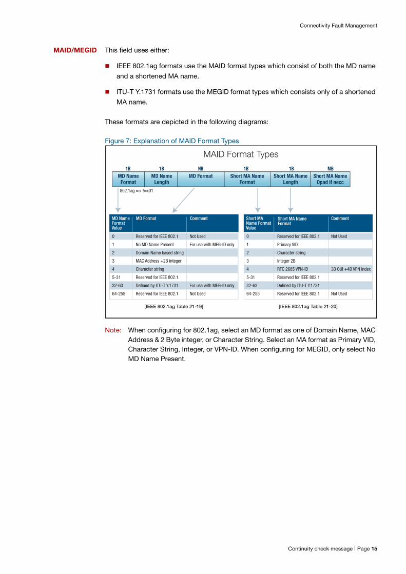
MAID/MEGID This field uses either:
IEEE 802.1ag formats use the MAID format types which consist of both the MD name
and a shortened MA name.
ITU-T Y.1731 formats use the MEGID format types which consists only of a shortened
MA name.
These formats are depicted in the following diagrams:
Figure 7: Explanation of MAID Format Types
Note: When configuring for 802.1ag, select an MD format as one of Domain Name, MAC Address & 2 Byte integer, or Character String. Select an MA format as Primary VID, Character String, Integer, or VPN-ID. When configuring for MEGID, only select No MD Name Present.
1B 1B NB 1B 1B MBMD Name
FormatMD Name
LengthMD Format Short MA Name
FormatShort MA Name
LengthShort MA Name
Opad if necc
MD NameFormatValue
MD Format Comment
0 Reserved for IEEE 802.1 Not Used
1 No MD Name Present For use with MEG-ID only
2 Domain Name based string
3 MAC Address +2B integer
4 Character string
5-31 Reserved for IEEE 802.1
32-63 Defined by ITU-T Y.1731 For use with MEG-ID only
64-255 Reserved for IEEE 802.1 Not Used
Short MAName FormatValue
Short MA NameFormat
Comment
0 Reserved for IEEE 802.1 Not Used
1 Primary VID
2 Character string
3 Integer 2B
4 RFC 2685 VPN-ID 3B OUI +4B VPN Index
5-31 Reserved for IEEE 802.1
32-63 Defined by ITU-T Y.1731
64-255 Reserved for IEEE 802.1 Not Used
[IEEE 802.1ag Table 21-19] [IEEE 802.1ag Table 21-20]
MAID Format Types
802.1ag => !=x01
Continuity check message | Page 15
Connectivity Fault Management
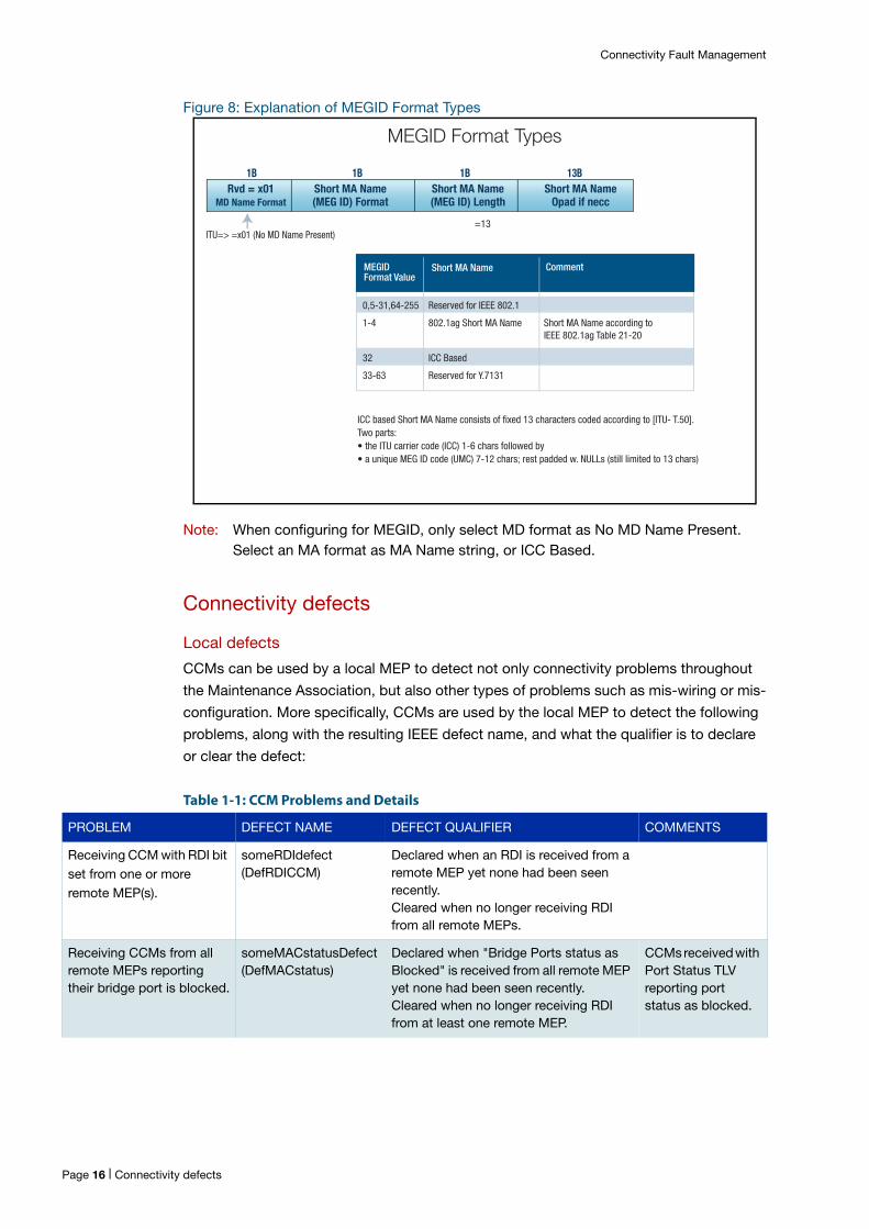
Figure 8: Explanation of MEGID Format Types
Note: When configuring for MEGID, only select MD format as No MD Name Present. Select an MA format as MA Name string, or ICC Based.
Connectivity defects
Local defects
CCMs can be used by a local MEP to detect not only connectivity problems throughout
the Maintenance Association, but also other types of problems such as mis-wiring or mis-
configuration. More specifically, CCMs are used by the local MEP to detect the following
problems, along with the resulting IEEE defect name, and what the qualifier is to declare
or clear the defect:
Table 1-1: CCM Problems and Details
1B 1B 1B 13BRvd = x01
MD Name FormatShort MA Name(MEG ID) Format
Short MA NameOpad if necc
Short MA Name(MEG ID) Length
MEGIDFormat Value
Short MA Name Comment
0,5-31,64-255 Reserved for IEEE 802.1
1-4 802.1ag Short MA Name Short MA Name according to
32 ICC Based
33-63 Reserved for Y.7131
ITU=> =x01 (No MD Name Present)=13
MEGID Format Types
ICC based Short MA Name consists of fixed 13 characters coded according to [ITU- T.50].Two parts:• the ITU carrier code (ICC) 1-6 chars followed by• a unique MEG ID code (UMC) 7-12 chars; rest padded w. NULLs (still limited to 13 chars)
IEEE 802.1ag Table 21-20
PROBLEM DEFECT NAME DEFECT QUALIFIER COMMENTS
Receiving CCM with RDI bit set from one or more remote MEP(s).
someRDIdefect(DefRDICCM)
Declared when an RDI is received from a remote MEP yet none had been seen recently.Cleared when no longer receiving RDI from all remote MEPs.
Receiving CCMs from all remote MEPs reporting their bridge port is blocked.
someMACstatusDefect(DefMACstatus)
Declared when "Bridge Ports status as Blocked" is received from all remote MEP yet none had been seen recently.Cleared when no longer receiving RDI from at least one remote MEP.
CCMs received with Port Status TLV reporting port status as blocked.
Page 16 | Connectivity defects
Connectivity Fault Management
Note: Defect Name shown is the 802.1ag variable name (along with the MIB equivalent name).
Remote defects
When any of the following defects are declared by the local MEP, the local MEP will inform
the remote MEP(s) by sending a CCM with the RDI bit set:
someRMEPCCMdefect
someMACstatusDefect
errorCCMdefect
xconCCMdefect
Connectivity alarms
802.1ag supports the concept of alarms. Alarms are defined as defects that last for a
certain amount of time, generally 2.5 seconds. Alarms are cleared when the defect has
abated for a longer period of time, generally 10 seconds. Alarms are intended to alert a
network operator about a defect’s occurrence as well as its abatement. To allow network
operators to limit notifications by alarm type, 802.1ag provides for a priority for the
defects discussed above, and allows the network operator to configure which priorities
they care to be notified about. Other alarms are noted by the system but an alarm
notification is not raised.
Receiving CCMs from 1 or more remote MEPs reporting their bridge interface is down.
someMACstatusDefect(DefMACstatus)
Declared when an "Interface status is Down" is received from a remote MEP yet none had been seen recently.Cleared when no longer receiving "Interface status as Down" from all remote MEPs.
CCMs received with Interface Status TLV reporting Interface status as down.
Not receiving CCMs from 1 or more remote MEP(s).
someRMEPCCMDefect(DefRemoteCCM)
Declared when no CCM has been received from at least one remote MEP within 3.5 times the agreed upon interval.Cleared when CCMs are received from all remote MEPs within 3.5 times the agreed upon interval.
CCM not received in 3.5 x interval.
Received CCM with correct MAID and Level, but MEP ID is not one that is configured or same as mine; or MEP ID is correct but the interval in packet doesn't match the configured interval.
errorCCMdefect(DefErrorCCM)
Declared when one of these errors occurs.Cleared when no errors occur for 3.5 x the errored Frame's interval field.
Tends to track packet with slowest interval.
Received CCM with wrong MAID or wrong level.
xconCCMdefect(DefXconCCM)
Declared when one of these errors occurs.Cleared when no errors occur for 3.5 x the errored Frame's interval field.
Tends to track packet with slowest interval.
PROBLEM DEFECT NAME DEFECT QUALIFIER COMMENTS
Connectivity alarms | Page 17
Connectivity Fault Management
How to Use this Feature
CFM configuration
The following section provides an overview for configuring CFM.
Enable CFM
CFM is enabled automatically and can not be disabled.
Configure the MD
To create a maintenance domain and configure its parameters, or to get back into an
existing instance's context, use the following command:
awplus(config)#ethernet cfm domain-name <domain-name> md-type {character-string md-type-name <md-type-name>| dns-based md-type-name <md-type-name>| mac md-type-name <md-type-name>| no-name}level <level>
The following parameters are available:
Domain Object Name - the MD name for the managed object.
Domain Name and Type - the MD name part of the MAID field that appears in the
CCM. There are different formats and conventions for the name depending on type.
Note: The user is not allowed to configure multiple MD managed objects that use the same md-type and md-type-name. The exception is md-type = “no-name” which can be used across multiple MD managed objects.
The types are:
Character-based - a character string of 1 to 43 characters. This character-based string plus the short MA name that is configured for an MA make up the MAID field in a CCM packet.
DNS-based - Domain Name-like string of 1 to 43 characters. This is a globally unique text string derived from a DNS name. This DNS-based string plus the short MA name that is configured for an MA make up the MAID field in a CCM packet.
MAC-based - MAC address + 2-octet (unsigned) integer in the form of HHHH.HHHH.HHHH:<2-octet integer>. This MAC-based string plus the short MA name that is configured for an MA make up the MAID field in a CCM packet.
No name - the MD name does not appear in the CCM packet, only the short MA name is used as the MEG-id for ITU compliance.
Level - the level that the MD provides for its MAs.
To re-enter the MD context, use the following command:
awplus(config)#ethernet cfm domain-name <domain-name>
Page 18 | CFM configuration
Connectivity Fault Management
Once in the MD instance, the service (also known as the MA) can be subsequently
configured.
To destroy an MD instance, use the following where <md-name> must match the value
that was used when the instance was created:
awplus(config)#no Ethernet cfm domain-name <md-name>
Note: When the MD is destroyed, the MAs associated with this MD are also destroyed without prompting the user to first delete any associated MAs. Similarly, any local MEPs configured that are associated with the MAs are also destroyed without prompting the user to first delete them.
Configure the MA
Enter the CLI MD context for the MD instance as described in the Configure the MD
section. Afterwards, any MAs created under this MD context are associated with the MD
instance.
To create the MA and set its parameters, use the following command:
awplus(config-ether-cfm)#service ma-name <ma-name> ma-type {icc| integer|primary-vid|string|vpn-id} ma-type-name <ma-type-name>[vlan <primary-vid> [mip-creation {none}]]
The following parameters are available:
MA Name - the MA name for the MA managed object.
MA Short Name and Type - the short MA name that appears in the CFM CCM packet.
There are different formats types for the MA name that the user can choose from:
ICC-based - a 13 byte character string consisting of a 1 to 6 character ITU Carrier Code (ICC) plus a 1 to 6 character Unique MEGID (UMC) code for the name. Any remaining characters are padding out with NULLs in the frame to fill out the 13 bytes. This can only be used with MD whose name md-type is set to "No name".
Integer-based - a number up to 2 Bytes (0..65535).
Primary-vid-based - the VLAN ID number that has been assigned to the MA as the primary VLAN.
String-based - a string of 1 to 45 characters.
VPN-ID-based - a 7 Byte value divided into two parts. The first part makes up the VPN's OUI which is three octets. The remaining four octets make up the VPN Index. The format is HHHHHH.HHHHHHHH, where H is a hexadecimal digit.
Note: If the MD (for this MA) is configured to use md-type=no-name, then this MA is not allowed to be configured with the same ma-type and ma-type-name as any other
Step 1. Enter the CLI MD context
Step 2. Create the MA
CFM configuration | Page 19
Connectivity Fault Management
MA on this MD or across multiple MDs. This is because the MA is the only entity providing the CCM names in the messages, and these must be unique.
VLAN - This is the primary VLAN ID for the MA. If the MA is used for link-locals, then
VLAN ID is not used.
Note: If a VLAN is destroyed and that VLAN is also a Primary VLAN configured for one or more MAs, those MAs are also destroyed without prompting the user to first delete any associated MAs. Similarly any local MEPs configured that are associated with the MAs are also destroyed without prompting the user to first delete them.
After this command is used, then the following can be configured as each has an
association with this MA:
Local MEPs (configured within the interface port or interface lag context but associates
with this MA). For more information see the Configure local MEPs section.
Remote MEPs (configured within the MD context but associates with this MA). For
more information see the Configure remote MEPs section.
CCM interval (configured within the MD context but associates with this MA). For more
information see the MA CCM - Continuity Check (CC) Interval section.
After creating the MA, its parameters can not be changed. In order to change parameters,
the MA must be destroyed and recreated. To destroy an MA instance, use the following
where <md-name> must match the value that was used when the instance was created:
awplus(config-ether-cfm)#no service <ma-name>
Note: This command will destroy all local MEPs, and remote MEPs that are associated with the MA. The user is not prompted concerning destruction of these.
Page 20 | CFM configuration
Connectivity Fault Management
Configure local MEPs
Configure the interface that the MEP will reside on by entering the CLI context for the
interface port of interest.
Identify the MA the local MEP is to be associated with, as well as the MD the MA is
associated with (in order to determine the MD name and level the MEP will use):
MD Identity - the same domain-name object <domain-name> that was used when
creating the MD.
MA Identity - the same service ma-name object <ma-name> that was used when
creating the MA.
Use the following command:
awplus(config-if)#ethernet cfm mep {down|up} mpid <mep-id> domain-name <domain-name> ma-name <ma-name>
MEP Direction: Up or Down - whether the local MEP is an Up MEP or a Down MEP.
In the initial implementation only "Down" is supported. If the user specifies "Up" the
command will fail with a message "Configuring an UP MEP is not supported".
MEP-id - the MEP ID for this MEP <1-8191>. It must be unique for all the MEPs (both
local and remote MEPs) in the MA.
This command serves two purposes:
1. Creates the local MEP instance if it does not exist, and
2. Re-enters the local MEP instance if created prior. To re-enter the context for this instance, the command and its parameters have to be repeated exactly as they were used for creation.
Once in the local MEP context instance, the following can be further configured or have
further operations performed on this local MEP:
Admin or "active" state of the local MEP - "True" sets the administrative state to "Up".
"False" sets the administrative state to "Down". By default the state is Admin Down.
Continuity Check - configurations for Continuity Check are done in this context but is
covered in the CCM section of this document.
Clear various local MEP attributes to default values - several of these attributes pertain
to various MEP specific functions such as CCM and are covered later on.
Step 1. Configure the MEP interface
Step 2. Identify the MA for the local MEP
Step 3. Configure the local MEP
CFM configuration | Page 21

Connectivity Fault Management
To change the Admin or "active" state of the MEP use the following command:
awplus(config-if-eth-cfm-mep)#mep active <true|false>
or can also use the following command to change the active state to "false":
awplus(config-if-eth-cfm-mep)#clear active
To destroy a local MEP, use the following, using the same parameters that were used to
create the local MEP:
awplus(config-if)#no ethernet cfm mep {down|up} mpid <mep-id> domain-name <domain-name> ma-name <ma-name>
Configure remote MEPs
A remote MEP is called crosscheck in the AlliedWare Plus CLI. A remote MEP is
configured for a given MA, so the MA name and the associated MD name have to be
specified.
Enter the CLI MD context for the MD instance as described in the Configure the MD
section.The MA that the remote MEP is associated with is identified by the same MA
object ma-name <ma-name> that was used when the MA was created. Since the MA
does not have a CLI context, this will be specified as a parameter in the command line.
Once this is done, use the following command:
awplus(config-ether-cfm)#mep crosscheck mpid <rmep-id> ma-name <ma-name> [mac <HHHH.HHHH.HHHH>]
The following parameters are available:
MEP-id - the unique MEP ID for this remote MEP <1-8191>. The ID should be unique
within all the remote MEPs and local MEPs in the MA.
Remote MEP's MAC address - an optional parameter. This is needed if CCMs are sent
unicast to a remote MEP. The MAC address format is HHH.HHHH.HHHH. Otherwise,
CCMs are sent as multicast by default.
Once the remote MEP information has been configured, no other configuration regarding
the remote MEP is needed.
To remove remote MEP information, use the following command:
awplus(config-ether-cfm)#no mep crosscheck mpid <rmep-id> ma-name <ma-name>
Step 1. Enter the CLI context
Step 2. Configure the remote MEP
Page 22 | CFM configuration
Connectivity Fault Management
CCM configuration
MA CCM - Continuity Check (CC) Interval
For the MA, the only CCM parameter of interest is the Continuity Check (CC) Interval
(CCI). The CCI is the time in-between the sending of CCMs by each local MEP, as well as
the expected interval for receiving CCMs from each remote MEP.
Re-enter the MD instance CLI context by using the same MD object domain-name
<domain-name> that was used when the MD was created. The MA that the CC Interval is
being configure for is identified by the same MA object ma-name <ma-name> that was
used when the MA was created. Since the MA does not have a CLI context, this will be
specified as a parameter in the command line.
Once in the MD context, to set the interval, use the following command:
awplus(config-ether-cfm)#cc ma-name <ma-name> interval <interval>
Interval - the CCM interval for all local MEPs in the MA.
Table 1-2: CCM Interval Values
In the future, certain AlliedWare Plus platforms will be able to support 3 ms and 10 ms
intervals using hardware assistance. For those intervals not supported, if the user
attempts to select such intervals, they will be informed that the interval is not supported.
Local MEP CCM - Enable CCM
CCM needs to be enabled in order to perform CFM functions.
Note: The local MEP has to be enabled as well using mep active true. Otherwise, attempting to enable CCMs will result in the message “Error. MEP is not configured as active”.
Step 1. Enter the CLI context
Step 2. Configure the interval
INTERVAL DESCRIPTION
1 CCI of 3 milliseconds. This interval will be available in the future. For now, the user will be informed “Interval not supported”.
2 CCI of 10 milliseconds. This interval will be available in the future. For now, the user will be informed “Interval not supported”.
3 CCI of 100 milliseconds.
4 CCI of 1 second. This is the default value.
5 CCI of 10 seconds.
6 CCI of 1 minute.
7 CCI of 10 minutes.
CCM configuration | Page 23
Connectivity Fault Management
Enter the local MEP CLI context by entering the interface context of the interface that the
local MEP resides on.
Re-enter the local MEP context by re-entering the identifying parameters that were used
at local MEP creation time as described in Configure the local MEP.
To enable or disable CCM processing on a local MEP, use the following command:
awplus(config-if-eth-cfm-mep)#cc {multicast|unicast rmpid <rmep-id>} state {enable|disable}
Multicast or Unicast - specify whether this local MEP will send CCMs using multicast
(to one or more remote MEPs) or unicast (to an individual remote MEP).
Remote MEP ID (Unicast) - if unicasting to a remote MEP, specify the remote MEP's
MEP ID. If unicast is chosen, CCM will lookup the remote MEP ID of the MD/MA that
this local MEP belongs to in order to get the configured unicast MAC address of the
remote MEP.
State (Up or Down) - use "Enable" to put the CCM function in an "Up" state and have
it process CCMs. Use "Disable" to put it in a "Down" state and disable CCM
processing.
The priority for sending/receiving CCMs can be set. The default is 7 (highest priority).
CCMs should be the highest priority message and it is recommended not to change this
setting.
awplus(config-if-eth-cfm-mep)#mep ccm-ltm-priority <0-7>
Local MEP CCM - Connectivity alarms
This section covers the configuration for alarms that can be generated based on defects
detected by a local MEP that is running CCM. 802.1ag refers to alarms as Fault
Notification Generation (FNG).
Enter the local MEP CLI context by getting into the interface context of the interface that
the local MEP resides on.
Step 1. Enter the CLI context
Step 2. Enter the MEP parameters
Step 3. Enable CCM processing
Step 1. Enter the CLI context
Page 24 | CCM configuration
Connectivity Fault Management
Re-enter the local MEP context by re-entering the identifying parameters that were used
at local MEP creation time as described in Configure the local MEP.
Use the following commands to set the various values:
awplus(config-if-eth-cfm-mep)#mep fng-alarm-time <soak-time>
Alarm Time - the amount of time a defect condition exists (or soaked) before an alarm is
declared. The soak time is an interval of 250 to 1000 in increments of 10 ms. For example,
“250” would equate to 2.5 seconds. The default is 2.5 seconds.
awplus(config-if-eth-cfm-mep)#reset-fng-time <abate-time>
Reset Time - the amount of time that a defect condition abates before an alarm is cleared
(reset). The abate time is an interval of 250 to 1000 in increments of 10 ms. For example,
“1000” would equate to 10 seconds. The default is 10 seconds.
awplus(config-if-eth-cfm-mep)#lowest-priority-defect <defect-priority>
Lowest Alarm Priority Defect - of the local defects listed above, each has a relative
priority over the others (the relative priority is listed in the table below). The defect priority
specifies the lowest defect that has to occur before an alarm can be generated. Any
priority less than this will not result in an alarm notification. Values are from 1 to 6. The
default is 2.
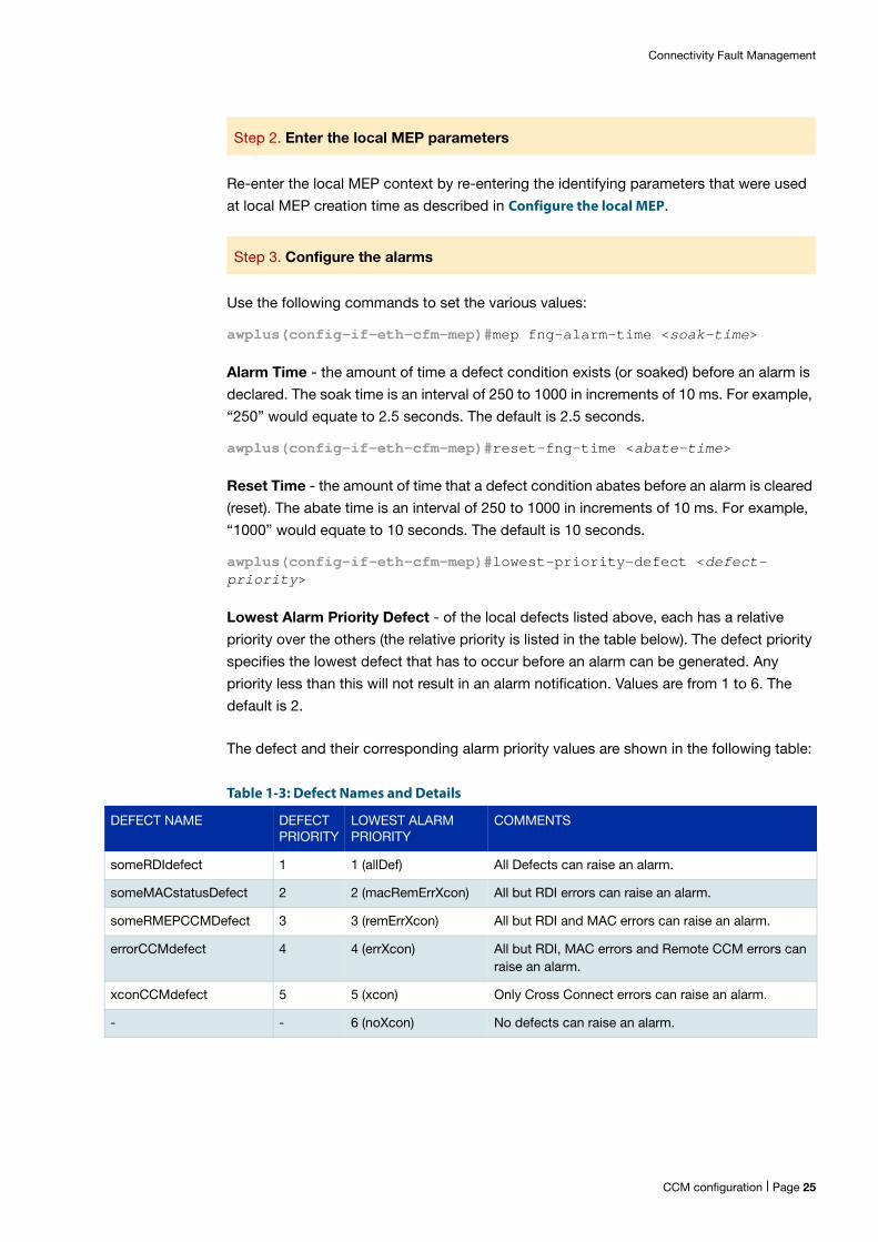
The defect and their corresponding alarm priority values are shown in the following table:
Table 1-3: Defect Names and Details
Step 2. Enter the local MEP parameters
Step 3. Configure the alarms
DEFECT NAME DEFECT PRIORITY
LOWEST ALARM PRIORITY
COMMENTS
someRDIdefect 1 1 (allDef) All Defects can raise an alarm.
someMACstatusDefect 2 2 (macRemErrXcon) All but RDI errors can raise an alarm.
someRMEPCCMDefect 3 3 (remErrXcon) All but RDI and MAC errors can raise an alarm.
errorCCMdefect 4 4 (errXcon) All but RDI, MAC errors and Remote CCM errors can raise an alarm.
xconCCMdefect 5 5 (xcon) Only Cross Connect errors can raise an alarm.
- - 6 (noXcon) No defects can raise an alarm.
CCM configuration | Page 25
Connectivity Fault Management
Note: The name within parentheses is the 802.1ag MIB name for the Lowest Alarm Priority.
Note: In general, if any of the defects with priority 2-5 are detected by the local MEP, an RDI will be sent to its remote MEPs. However, 802.1ag specifies that an RDI will not be sent if the corresponding defect has its priority less than the lowest alarm priority. As such, it is recommended to set the Lowest Alarm priority to 2 or 1.
These alarm parameters can be reset to their default values individually (fng-alarm-time
to 2.5 s, reset-fng-alarm-time to 10 s and lowest-priority-defect to 2 (macRemErrXcon)
by using the clear command:
awplus(config-if-eth-cfm-mep)#clear fng-alarm-time
awplus(config-if-eth-cfm-mep)#clear reset-fng-alarm-time
awplus(config-if-eth-cfm-mep)#clear lowest-priority-defect
Alternatively, all the alarm parameters can be reset to their default values by using the
following clear command:
awplus(config-if-eth-cfm-mep)#clear all
Configuration ExamplesTwo switches, IE200-1 and IE200-2 are connected together using interface port1.0.2 on
IE200-1 and interface port1.0.3 on IE200-2. Both of these interfaces have tagged VLAN
100. In order to ensure connectivity exists between the two at the VLAN level, CCMs are
configured to run on these ports for VLAN 100. This could be used for example when
G.8032 (Ethernet Ring Protection Switching) is configured and VLAN 100 is the R-APS
control VLAN. To keep the example simple, MD and MA names used by CCMs are based
on character strings. The level used by CCMs is 3.
Configure an MD and an associated MA:
IE200-1(config)#ethernet cfm domain-name MD-INST2 md-type character-string md-type-name MD-12L3 level 3
IE200-1(config-ether-cfm)#service ma-name MA-INST2-1 ma-type string ma-type-name MA-12V100 vlan 100
IE200-1(config-ether-cfm)#
IE200-2(config)#ethernet cfm domain-name MD-INST2 md-type character-string md-type-name MD-12L3 level 3
IE200-2(config-ether-cfm)#service ma-name MA-INST2-1 ma-type string ma-type-name MA-12V100 vlan 100
IE200-2(config-ether-cfm)#
Step 1. Configure an MD and MA on Switch#1
Step 2. Configure an MD and MA on Switch#2
Page 26 | CCM configuration
Connectivity Fault Management
Configure a local MEP on the interface and VLAN with differing MEP IDs:
IE200-1(config)#interface port1.0.2
IE200-1(config-if)#ethernet cfm mep down mpid 12 domain-name MD-INST2 ma-name MA-INST2-1
IE200-1(config-if-eth-cfm-mep)#
IE200-2(config)#interface port1.0.3
IE200-2(config-if)#ethernet cfm mep down mpid 21 domain-name MD-INST2 ma-name MA-INST2-1
IE200-2(config-if-eth-cfm-mep)#
Configure a remote MEP on each switch:
IE200-1(config-if-eth-cfm-mep)#exit
IE200-1(config-if)#exit
IE200-1(config)#ethernet cfm domain-name MD-INST2
IE200-1(config-ether-cfm)#mep crosscheck mpid 21 ma-name MA-INST2-1
IE200-1(config-ether-cfm)#
IE200-2(config-if-eth-cfm-mep)#exit
IE200-2(config-if)#exit
IE200-2(config)#ethernet cfm domain-name MD-INST2
IE200-2(config-ether-cfm)#mep crosscheck mpid 12 ma-name MA-INST2-1
IE200-2(config-ether-cfm)#
Enable CCM processing using multicast for the local MEP:
IE200-1(config-ether-cfm)#exit
IE200-1(config)#interface port1.0.2
IE200-1(config)#ethernet cfm mep down mpid 12 domain-name MD-INST2 ma-name MA-INST2-1
IE200-2(config-if-eth-cfm-mep)#mep active true
IE200-1(config-if-eth-cfm-mep)#cc multicast state enable
Step 3. Configure a local MEP and VLAN on Switch#1
Step 4. Configure a local MEP and VLAN on Switch#2
Step 5. Configure a remote MEP on Switch#1
Step 6. Configure a remote MEP on Switch#2
Step 7. Enable CCM processing on Switch#1
CCM configuration | Page 27
Connectivity Fault Management
IE200-2(config-ether-cfm)#exit
IE200-2(config)#interface port1.0.3
IE200-2(config-if)#ethernet cfm mep down mpid 21 domain-name MD-INST2 ma-name MA-INST2-1
IE200-2(config-if-eth-cfm-mep)#mep active true
IE200-2(config-if-eth-cfm-mep)#cc multicast state enable
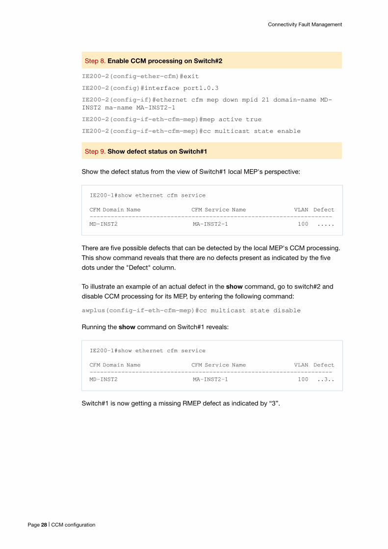
Show the defect status from the view of Switch#1 local MEP's perspective:
There are five possible defects that can be detected by the local MEP's CCM processing.
This show command reveals that there are no defects present as indicated by the five
dots under the "Defect" column.
To illustrate an example of an actual defect in the show command, go to switch#2 and
disable CCM processing for its MEP, by entering the following command:
awplus(config-if-eth-cfm-mep)#cc multicast state disable
Running the show command on Switch#1 reveals:
Switch#1 is now getting a missing RMEP defect as indicated by “3”.
Step 8. Enable CCM processing on Switch#2
Step 9. Show defect status on Switch#1
IE200-1#show ethernet cfm service
CFM Domain Name CFM Service Name VLAN Defect---------------------------------------------------------------------MD-INST2 MA-INST2-1 100 .....
IE200-1#show ethernet cfm service
CFM Domain Name CFM Service Name VLAN Defect---------------------------------------------------------------------MD-INST2 MA-INST2-1 100 ..3..
Page 28 | CCM configuration
Connectivity Fault Management
Show Commands
Maintenance domain
Configuration
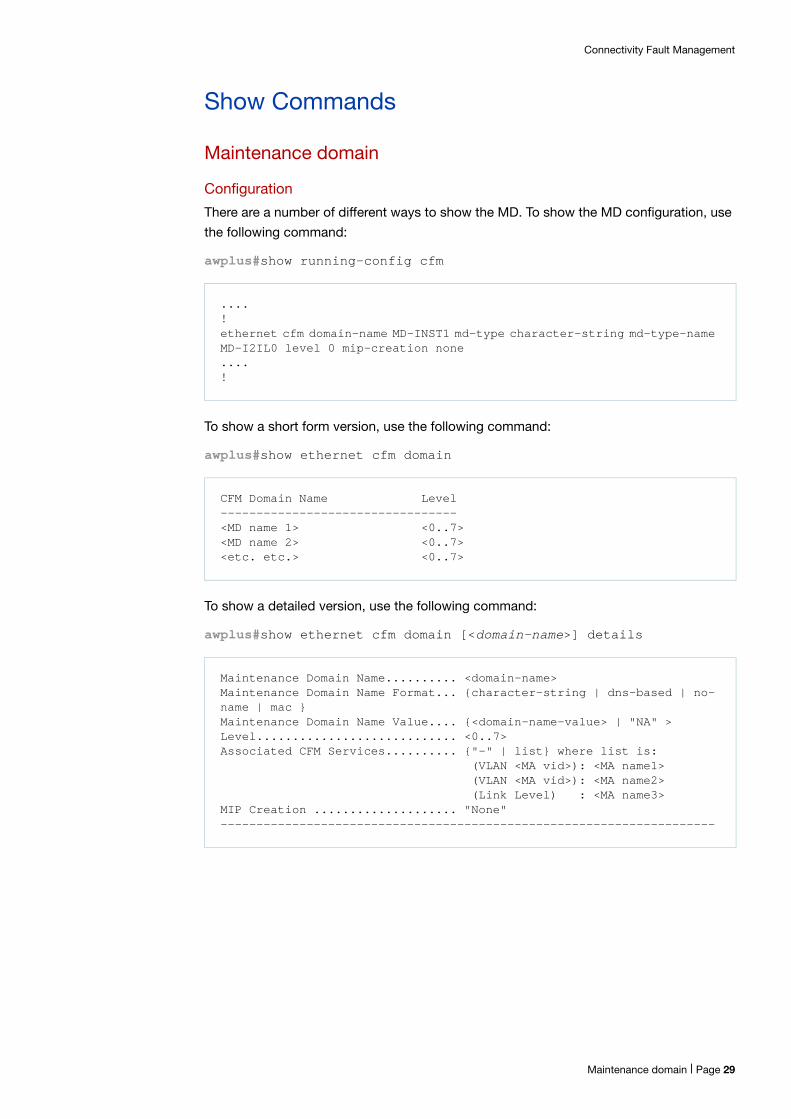
There are a number of different ways to show the MD. To show the MD configuration, use
the following command:
awplus#show running-config cfm
To show a short form version, use the following command:
awplus#show ethernet cfm domain
To show a detailed version, use the following command:
awplus#show ethernet cfm domain [<domain-name>] details
....!ethernet cfm domain-name MD-INST1 md-type character-string md-type-name MD-I2IL0 level 0 mip-creation none....!
CFM Domain Name Level ---------------------------------<MD name 1> <0..7><MD name 2> <0..7><etc. etc.> <0..7>
Maintenance Domain Name.......... <domain-name>Maintenance Domain Name Format... {character-string | dns-based | no-name | mac }Maintenance Domain Name Value.... {<domain-name-value> | "NA" >Level............................ <0..7>Associated CFM Services.......... {"-" | list} where list is: (VLAN <MA vid>): <MA name1> (VLAN <MA vid>): <MA name2> (Link Level) : <MA name3>MIP Creation .................... "None"---------------------------------------------------------------------
Maintenance domain | Page 29
Connectivity Fault Management
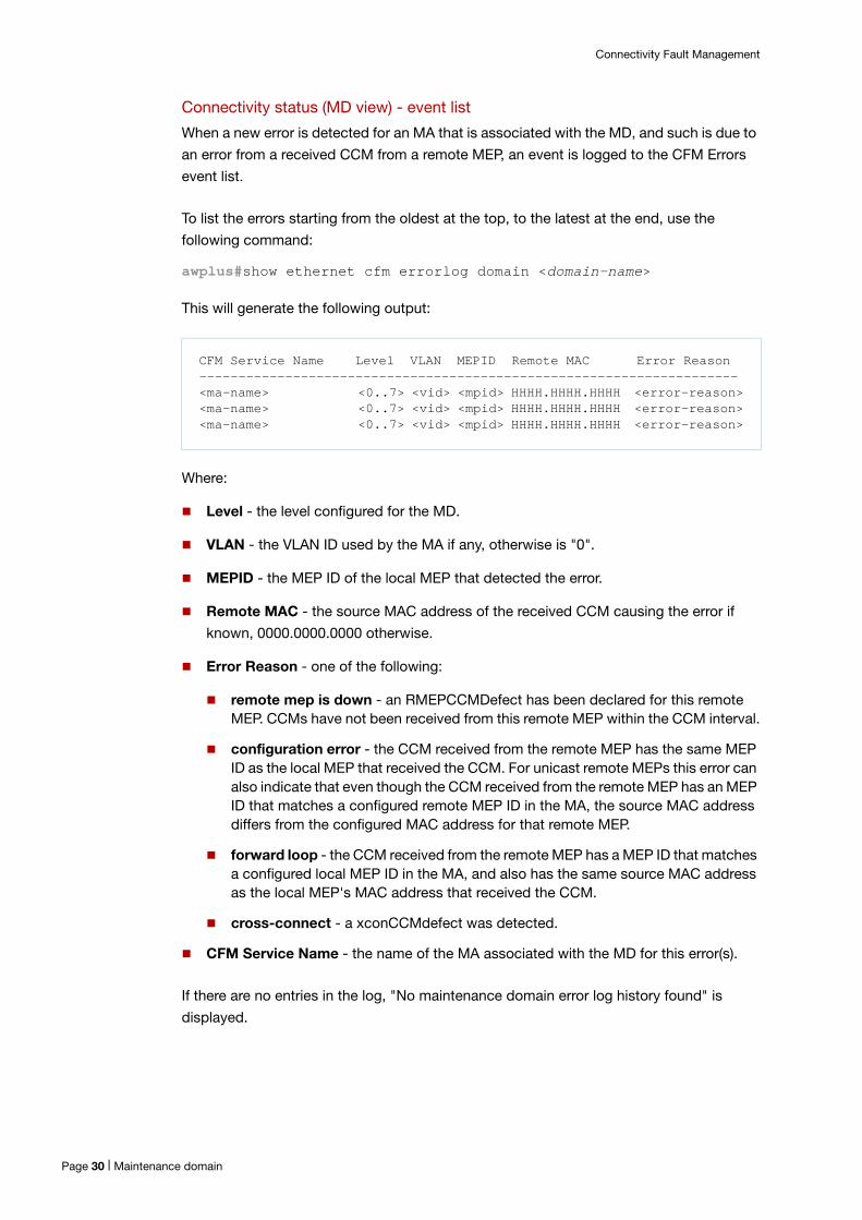
Connectivity status (MD view) - event list
When a new error is detected for an MA that is associated with the MD, and such is due to
an error from a received CCM from a remote MEP, an event is logged to the CFM Errors
event list.
To list the errors starting from the oldest at the top, to the latest at the end, use the
following command:
awplus#show ethernet cfm errorlog domain <domain-name>
This will generate the following output:
Where:
Level - the level configured for the MD.
VLAN - the VLAN ID used by the MA if any, otherwise is "0".
MEPID - the MEP ID of the local MEP that detected the error.
Remote MAC - the source MAC address of the received CCM causing the error if
known, 0000.0000.0000 otherwise.
Error Reason - one of the following:
remote mep is down - an RMEPCCMDefect has been declared for this remote MEP. CCMs have not been received from this remote MEP within the CCM interval.
configuration error - the CCM received from the remote MEP has the same MEP ID as the local MEP that received the CCM. For unicast remote MEPs this error can also indicate that even though the CCM received from the remote MEP has an MEP ID that matches a configured remote MEP ID in the MA, the source MAC address differs from the configured MAC address for that remote MEP.
forward loop - the CCM received from the remote MEP has a MEP ID that matches a configured local MEP ID in the MA, and also has the same source MAC address as the local MEP's MAC address that received the CCM.
cross-connect - a xconCCMdefect was detected.
CFM Service Name - the name of the MA associated with the MD for this error(s).
If there are no entries in the log, "No maintenance domain error log history found" is
displayed.
CFM Service Name Level VLAN MEPID Remote MAC Error Reason---------------------------------------------------------------------<ma-name> <0..7> <vid> <mpid> HHHH.HHHH.HHHH <error-reason><ma-name> <0..7> <vid> <mpid> HHHH.HHHH.HHHH <error-reason><ma-name> <0..7> <vid> <mpid> HHHH.HHHH.HHHH <error-reason>
Page 30 | Maintenance domain
Connectivity Fault Management
To clear this log, enter the following:
awplus#clear ethernet cfm errorlog domain <domain-name>
Note: Once the log clears but the error is still present, no new log entry is re-created.
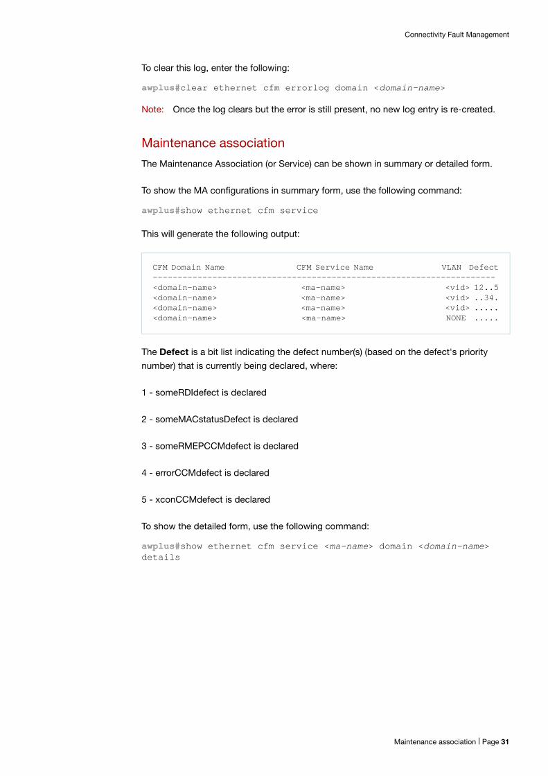
Maintenance association
The Maintenance Association (or Service) can be shown in summary or detailed form.
To show the MA configurations in summary form, use the following command:
awplus#show ethernet cfm service
This will generate the following output:
The Defect is a bit list indicating the defect number(s) (based on the defect's priority
number) that is currently being declared, where:
1 - someRDIdefect is declared
2 - someMACstatusDefect is declared
3 - someRMEPCCMdefect is declared
4 - errorCCMdefect is declared
5 - xconCCMdefect is declared
To show the detailed form, use the following command:
awplus#show ethernet cfm service <ma-name> domain <domain-name> details
CFM Domain Name CFM Service Name VLAN Defect---------------------------------------------------------------------<domain-name> <ma-name> <vid> 12..5<domain-name> <ma-name> <vid> ..34.<domain-name> <ma-name> <vid> .....<domain-name> <ma-name> NONE .....
Maintenance association | Page 31
Connectivity Fault Management
This will generate the following output:
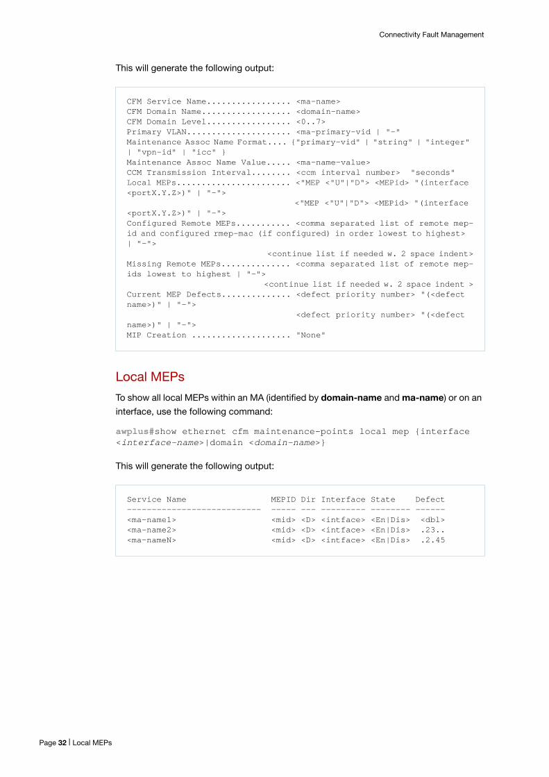
Local MEPs
To show all local MEPs within an MA (identified by domain-name and ma-name) or on an
interface, use the following command:
awplus#show ethernet cfm maintenance-points local mep {interface <interface-name>|domain <domain-name>}
This will generate the following output:
CFM Service Name................. <ma-name>CFM Domain Name.................. <domain-name>CFM Domain Level................. <0..7>Primary VLAN..................... <ma-primary-vid | "-" Maintenance Assoc Name Format.... {"primary-vid" | "string" | "integer" | "vpn-id" | "icc" }Maintenance Assoc Name Value..... <ma-name-value>CCM Transmission Interval........ <ccm interval number> "seconds" Local MEPs....................... <"MEP <"U"|"D"> <MEPid> "(interface <portX.Y.Z>)" | "-"> <"MEP <"U"|"D"> <MEPid> "(interface <portX.Y.Z>)" | "-">Configured Remote MEPs........... <comma separated list of remote mep-id and configured rmep-mac (if configured) in order lowest to highest> | "-"> <continue list if needed w. 2 space indent>Missing Remote MEPs.............. <comma separated list of remote mep-ids lowest to highest | "-"> <continue list if needed w. 2 space indent >Current MEP Defects.............. <defect priority number> "(<defect name>)" | "-"> <defect priority number> "(<defect name>)" | "-">MIP Creation .................... "None"
Service Name MEPID Dir Interface State Defect --------------------------- ----- --- --------- -------- ------<ma-name1> <mid> <D> <intface> <En|Dis> <dbl><ma-name2> <mid> <D> <intface> <En|Dis> .23.. <ma-nameN> <mid> <D> <intface> <En|Dis> .2.45
Page 32 | Local MEPs
Connectivity Fault Management
Where:
Service Name - the MA service name.
MEPID - the MEP ID of the local MEP of interest within the MA.
Dir - the direction of this local MEP:
D - Down MEP.
U - Up MEP.
Note: Only Down MEP is currently supported.
Interface - the interface on which the local MEP resides.
State - whether the local MEP's CCM processing is enabled En or disabled Dis.
Defect - defect bit list <dbl> indicating which of 5 possible defects are currently being
detected with each bit showing the detected <defect-number> or "." if there is no
defect. The <defect-number> is defined below.
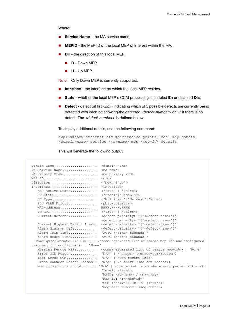
To display additional details, use the following command:
awplus#show ethernet cfm maintenance-points local mep domain <domain-name> service <ma-name> mep <mep-id> details
This will generate the following output:
Domain Name...................... <domain-name>MA Service Name.................. <ma-name>MA Primary VLAN.................. <ma-primary-vid>MEP ID........................... <mid>Direction........................ <"Down"|"Up">Interface........................ <interface> MEP Active State.............. <"True" | "False"> CC State...................... <"Enable|"Disable"> CC Type....................... <"Multicast"|"Unicast"|"None"> PDU VLAN Priority ............ <pbit-priority> MAC-address................... HHHH.HHHH.HHHH Tx-RDI........................ <"True" | "False"> Current Defects............... <defect-priority> "("<defect-name>")" <defect-priority> "("<defect-name>")" Current Highest Defect Alarm.. <defect-priority> "("<defect-name>")" Alarm Minimum Defect.......... <defect-priority> "("<defect-name>")" Alarm Trip Time............... "AUTO (<time> seconds)" Alarm Reset Time.............. "AUTO (<time> seconds)" Configured Remote MEP-IDs..... <comma separated list of remote mep-ids and configured rmep-mac (if configured)> | "None" Missing Remote MEPs........... <comma separated list of remote mep-ids> | "None" Error CCM Reason.............. "N/A" | <number> (<error-ccm-reason>) Last Error CCM................ "N/A" | <ccm-packet-info> Cross Connect Defect Reason... "N/A" | <number> (<cc-ccm-reason>) Last Cross Connect CCM........ "N/A" | <ccm-packet-info> where <ccm-packet-info> is: "Level: <level> "MAID: <md-name> / <ma-name>" "MEP ID: <rx-mep-id>" "CCM Interval: <0..7> (<time>)" "Sequence Number: <seq-number>
Local MEPs | Page 33
Connectivity Fault Management
Where:
Domain Name and MA Service Name - uniquely identify the MA this local MEP is
associated with.
MA Primary VLAN - the VLAN used by this MEP. A link-local MEP VLAN is indicated
by “-”.
MEP ID - the local MEP's ID.
Direction - the direction of the local MEP, either Down or Up.
Interface - the Interface port or Interface lag that the local MEP is configured against.
MEP Active State - the MEP’s configured administrative state; Up: True or Down:
False.
CC State - the MEP's CCM configured administrative state; Up: Enable or Down:
Disable.
CC Type - the configured CCM sending and receiving type, either multicast or unicast.
If not yet configured, it shows as None.
MAC Address - the local MEP's MAC address
Tx-RDI - whether this local MEP is sending RDI or not. An RDI is sent when one or more
of the following defects have been declared by the local MEP:
someRMEPCCMdefect
someMACstatusDefect
errorCCMdefect
xconCCMdefect
Defects - a list of defects the local MEP is currently detecting. The defect-priority
number and defect name:
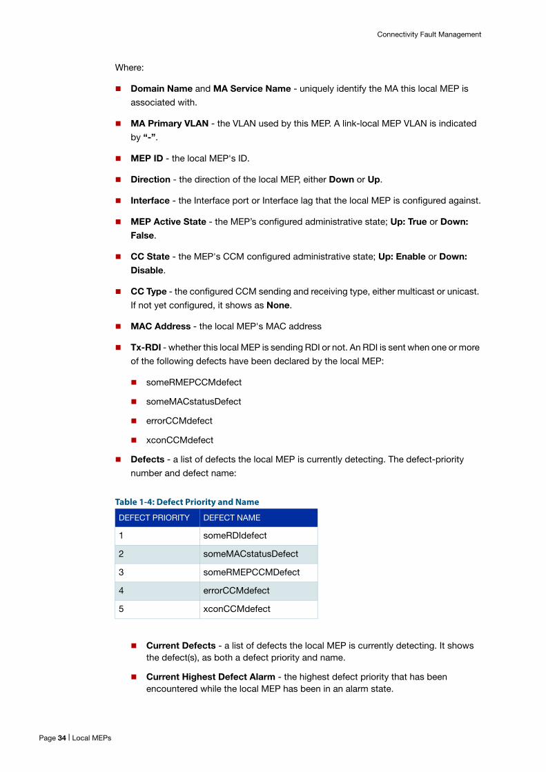
Table 1-4: Defect Priority and Name
Current Defects - a list of defects the local MEP is currently detecting. It shows the defect(s), as both a defect priority and name.
Current Highest Defect Alarm - the highest defect priority that has been encountered while the local MEP has been in an alarm state.
DEFECT PRIORITY DEFECT NAME
1 someRDIdefect
2 someMACstatusDefect
3 someRMEPCCMDefect
4 errorCCMdefect
5 xconCCMdefect
Page 34 | Local MEPs
Connectivity Fault Management
Alarm Minimum Defect - the minimum defect the local MEP has to see before declaring an alarm.
Alarm Trip Time - the amount of time the defect has to exist before an alarm is
declared.
Alarm Reset Time - the amount of time the defect has to abate before clearing the
alarm.
Configured Remote MEP IDs - a comma separated list of configured remote MEPs
(by MEP IDs) known by this local MEP. If the remote MEP also has a configured unicast
MAC address, the MEP ID will also include -HHHH.HHHH.HHHH.
Missing Remote MEPs - the remote MEPs (by MEP ID) that have been configured
against this local MEP but have not been heard from.
Error CCM Reason - the reason that the local MEP is detecting the errorCCMdefect
condition (if any):
1 - Wrong MEP ID Received - CCM received with correct level and MAID, but MEP ID has not been configured in this MA.
2 - My MEP ID Received - CCM received with correct level and MAID, but a MEP ID that is the same as a local MEP in this MA.
3 - CCM Interval Mismatch - CCM received with correct level and MAID, but CCM interval does not match that configured for this MA.
N/A - indicates there is no error CCM defect being detected.
Last Error CCM - if an errorCCMdefect condition is detected, portions of the CCM that
caused this condition are displayed.
Cross CCM Reason - the reason that the local MEP is detecting the xconCCMdefect
condition (if any):
1 - Wrong MAID - CCM received with correct level but incorrect MAID (mismatch in the domain name and/or short MA name versus configured).
2 - Wrong Level - CCM received with a level that is lower than the level configured for this local MEP's domain.
Last Cross Connect CCM - if a xconCCMdefect condition is detected, portions of the
CCM that caused this condition are displayed.
<ccm_packet_info> - the portions of a packet that are captured when an
errorCCMdefect or xconCCMdefect occurred:
MAID - the MD name and the MA name that is in the received CCM.
Level - the level that is in the received CCM.
MEP ID - the MEP ID that is in the received CCM.
CCM Interval - the CCM interval number and corresponding time (in ms, secs or mins) that is in the received CCM.
Sequence Number - the sequence number that is in the received CCM.
Local MEPs | Page 35
Connectivity Fault Management
Counters
To show the counters for all local MEPs in an MA, use the following command:
awplus#show ethernet cfm maintenance-points local mep domain <domain-name> service <ma-name> counters
To show the counters for all local MEPs on an interface, use the following command:
awplus#show ethernet cfm maintenance-points local mep interface <interface name> counters
This will generate the following output:
To show the counters for a specific local MEP within an MA, use the following command:
awplus#show ethernet cfm maintenance-points local mep domain <domain-name> service <ma-name> mep <mep-id> counters
This will generate the following output:
To clear the counter, use the following command:
awplus#clear mep counter domain <domain-name> service <ma-name>[mep <mep-id>]
If mep is not specified, it will clear the counters for all local MEPs in the MA.
Alarms
To show which local MEP is in an alarm state, and the defect that caused the alarm, use
the following command:
awplus#show mep-alarm status
CFM Service Name MEPID OOS-CCMs Sent-CCMs---------------------------------------------------------------<md-name> <mid> <ooscnt> <txcnt>MA-INST2-1 21 0 44840
Maintenance Points Local MEP CountersDomain Name...................... <domain-name>MA Service Name.................. <ma-name>MA Primary VLAN.................. <ma-primary-vid>MEP ID........................... <mid>Direction........................ "DOWN" | "UP"Interface........................ <interface> Tx CCM Count.................. <txcnt> Rx Out-of-Sequence CCM........ <ooscnt>
Page 36 | Local MEPs
Connectivity Fault Management
This will generate the following output:
Where:
CFM Domain Name - the domain name.
CFM Service Name - the MA name.
Active Alarms - the highest priority defect causing the alarm, one of the following:
someRDI, someMACstatus, someRMEPCCM, errorCCM, or xconCCM.
MEP - the local MEP's ID.
Remote MEP
To display information about the remote MEP, use the following command:
awplus#show ethernet cfm maintenance-points remote mep domain <domain-name> service <ma-name>
This will generate the following output:
Where:
CFM Domain Name and CFM Service Name - the instance identifiers that uniquely
identify the MA for the remote MEP(s) of interest.
To display information with additional details, use the following command:
awplus#show ethernet cfm maintenance-points remote mep domain <domain-name> service <ma-name> {mac <rmep-mac-address>|rmep <mep-id>} details
CFM Domain Name CFM Service Name MEP Active Alarms--------------------------- --------------- ---- ------<md-name> <ma-name> <mid> <mep-alarm><md-name> <ma-name> <mid> <mep-alarm><md-name> <ma-name> <mid> <mep-alarm><md-name> <ma-name> <mid> <mep-alarm>
CFM Domain Name: <md-name>CFM Service Name: <ma-name> RX RX Port IntfMEPID CCM RDI Stat Stat ------------------------------<mpid> <c> <r> <ps> <is> 2 Yes - Up Up 3 Yes - Up Up 4 Wait - - - 5 Yes Yes Blk Unkn 6 - - - - 12 Yes Yes Blk Down 13 Yes - Up Up
Remote MEP | Page 37
Connectivity Fault Management
This will generate the following output:
Where:
Remote MEPID - the remote MEP ID that is configured for this MA.
MAC Address - the configured or discovered MAC address of the remote MEP.
RX RDI - the current RDI being received from this remote MEP:
True - the last CCM received from the remote MEP has the RDI set. This means the remote MEP itself is seeing one of the following defects: someRMEPCCMDefect, someMACstatusDefect, errorCCMdefect, xconCCMdefect.
False - the last CCM received from the remote MEP does not have its RDI set.
Receiving CCMs - the current state of the 802.1ag remote MEP state machine:
Yes - RMEP_OK. CCMs are being received without any error.
Wait - RMEP_START. Still preparing to receive remote MEP CCMs without a timeout occurring.
Failed - RMEP_FAILED. While waiting to receive CCMs from a remote MEP, a timeout occurred.
- - the state machine is not running.
Port Status - if the CCM was received with a port status TLV, this indicates the last
value received, or "-" if none received.
Interface Status - if the CCM was received with an interface status TLV, this indicates
the last value received, or "-" if none received.
Show all details
To show details of all MDs, MAs, local MEPs, and remote MEPs in detailed form, use the
following command:
awplus#show ethernet cfm details
The output is a repeat of the following show commands from above:
awplus#show ethernet cfm domain [<domain-name>] details
awplus#show ethernet cfm service <ma-name> domain <domain-name> details
CFM Service Name..... <ma-name>CFM Domain Name...... <md-name>Remote MEPID......... <remote-mep-id>Receiving CCMs....... <"Yes"|"Wait" | "Failed" | "-">RX RDI............... <"Yes"|"No" | "-">MAC Address.......... <HHHH.HHHH.HHHH | "-">Port Status.......... <"Up" | "Blk"/"Blocked" | "-">Interface Status..... <"Up" | "Down" | "Test"/"Testing" | "Dorm"/"Dormant" | "Unkn"/"Unknown" |"NotP"/"NotPresent" | "LLD"/"LowerLayerDown" | "-">
Page 38 | Show all details

awplus#show ethernet cfm maintenance-points local mep domain <domain-name> service <ma-name> mep <mep-id> details
awplus#show ethernet cfm maintenance-points local mep domain <domain-name> service <ma-name> mep <mep-id> counters
awplus#show ethernet cfm maintenance-points remote mep domain <domain-name> service <ma-name> {mac <rmep-mac-address>|rmep <mep-id>} details
The output loops through the hierarchy of MDs, then MAs within each MD, then local
MEPs within that MA, and finally remote MEPs within that MA.
C613-22103-00 REV A
NETWORK SMARTER
alliedtelesis.com
North America Headquarters | 19800 North Creek Parkway | Suite 100 | Bothell | WA 98011 | USA | T: +1 800 424 4284 | F: +1 425 481 3895
Asia-Pacific Headquarters | 11 Tai Seng Link | Singapore | 534182 | T: +65 6383 3832 | F: +65 6383 3830
EMEA & CSA Operations | Incheonweg 7 | 1437 EK Rozenburg | The Netherlands | T: +31 20 7950020 | F: +31 20 7950021
© 2017 Allied Telesis, Inc. All rights reserved. Information in this document is subject to change without notice. All company names, logos, and product designs that are trademarks or registered trademarks are the property of their respective owners.
Related Documents