1 Connections to 1993-1-8 © 2011 The Steel Construction Institute Well, what do you expect? Any dramatic changes? That BS 5950 was wrong? But gravity loads reduce by ≈ 8% • Can we use BS 5950 connections? Nominally pinned connections may also have to carry large tying forces? • How is this reconciled? – the results are not pinned.

Connections to EC3
Jan 26, 2016
Connections to EC3
Welcome message from author
This document is posted to help you gain knowledge. Please leave a comment to let me know what you think about it! Share it to your friends and learn new things together.
Transcript
1
Connections to 1993-1-8
© 2011 The Steel Construction Institute
Well, what do you expect?
Any dramatic changes? That BS 5950 was wrong?
But gravity loads reduce by ≈ 8%• Can we use BS 5950 connections?
Nominally pinned connections may also have to carry large tying forces?• How is this reconciled? – the results are not
pinned.

2
© 2011 The Steel Construction Institute
Objectives:
To reassure you about connection design
To alert you to the National Annex
© 2011 The Steel Construction Institute
EN 1993-1-8:
A bit on bolts and weld strength
A huge section on moment resistance• Like the “Green Book”
A huge section on stiffness calculation• New to the UK experience
A huge section on hollow section joints• Like CIDECT, Corus Publications etc

3
© 2011 The Steel Construction Institute
As expected:
Resistance based on the resistance of the components• Typically bolts, welds, plates
• We look for “the weakest link”
© 2011 The Steel Construction Institute
As expected:
When making assumptions about the distribution of internal forces:• The implied deformations must be realistic
• The assumed distribution of forces must acknowledge relative stiffnesses
Welds are not ductile, and bolts are not springs
4
© 2011 The Steel Construction Institute
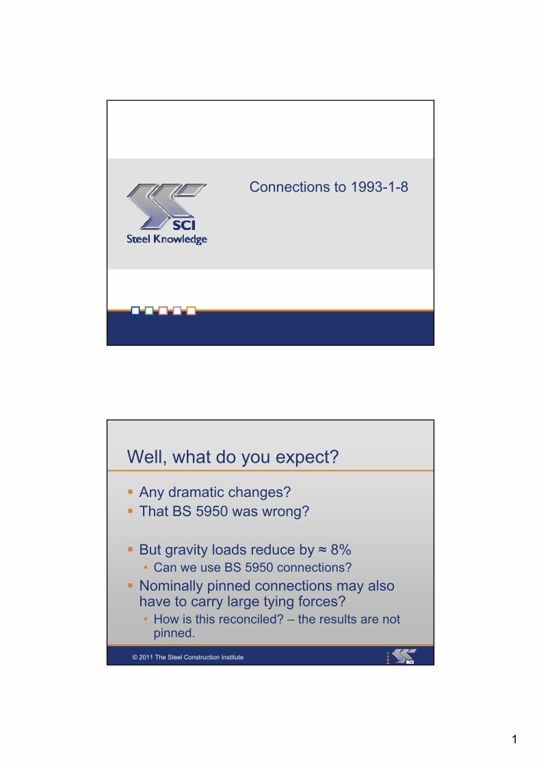
Bolt force distribution
L1
L2
L3
2T
2T x
2T x
L2
L1
L3
L1
2T x L1
2T x x L2L2
L1
2T x x L3L3
L1
=2T( L1 + + + …… )L2²L1 L3²
L1
© 2011 The Steel Construction Institute
Bolt force distibution

5
© 2011 The Steel Construction Institute
Component strengths
All require a partial safety factor, M
… to be taken from the National Annex
© 2011 The Steel Construction Institute
From the UK National Annex:

6
© 2011 The Steel Construction Institute
From the UK National Annex:
© 2011 The Steel Construction Institute
Bolts
Plenty of grades:
4.6, 4.8, 5.6, 5.8, 6.8, 8.8, 10.9
Some limitations in the UK NA:
4.6, 4.8, 5.6, 5.8, 6.8, 8.8, 10.9

7
© 2011 The Steel Construction Institute
Bolts in shear
M2
ubvRdv, γ
AfαF
v = 0.6 for 4.6 and 8.8fub = 400 N/mm2 for 4.6
= 800 N/mm2 for 8.8A = tensile area, if threads in the shear planeA = gross area, if threads in the unthreaded shank
UK practice is fully threaded bolts, so use of the tensile area is strongly recommended
© 2011 The Steel Construction Institute
Bolts in shear
M20 8.8 bolts, A = 245 mm2
kN94.125.1
2458006.0
M2
ubvRdv,
γ
AfαF
EC3 BS 595094.1 kN 91.9 kN
8
© 2011 The Steel Construction Institute
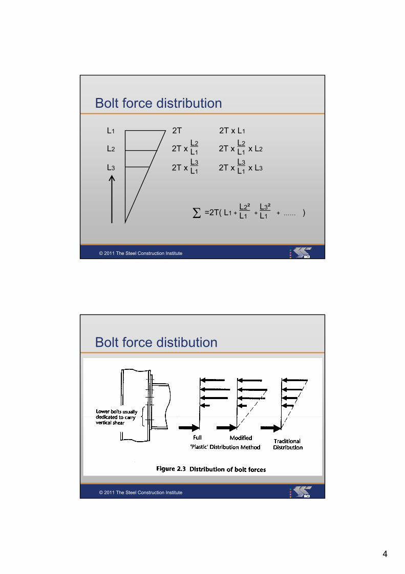
Bolts in Shear – 8.8
21513694.160.31993-1-8
21013291.958.9BS 5950
M30M24M20M16
2 % more to the Eurocode
© 2011 The Steel Construction Institute
Bolts in bearing – to BS 5950
bspbs ptdP
So for an M 20, in 10 mm S275 plate:
kNbs 92104601020 3 P
9
© 2011 The Steel Construction Institute
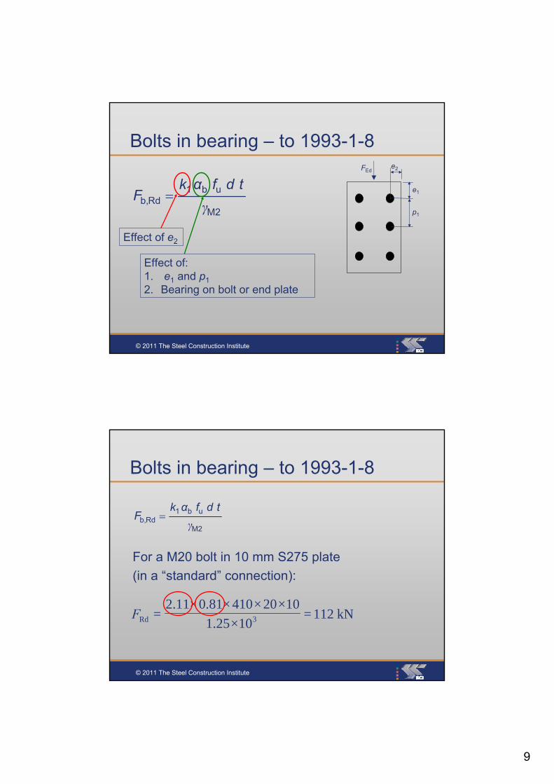
Bolts in bearing – to 1993-1-8
M2
ub1Rdb, γ
tdfαkF
Effect of e2
Effect of:1. e1 and p1
2. Bearing on bolt or end plate
e2FEd
e1
p1
© 2011 The Steel Construction Institute
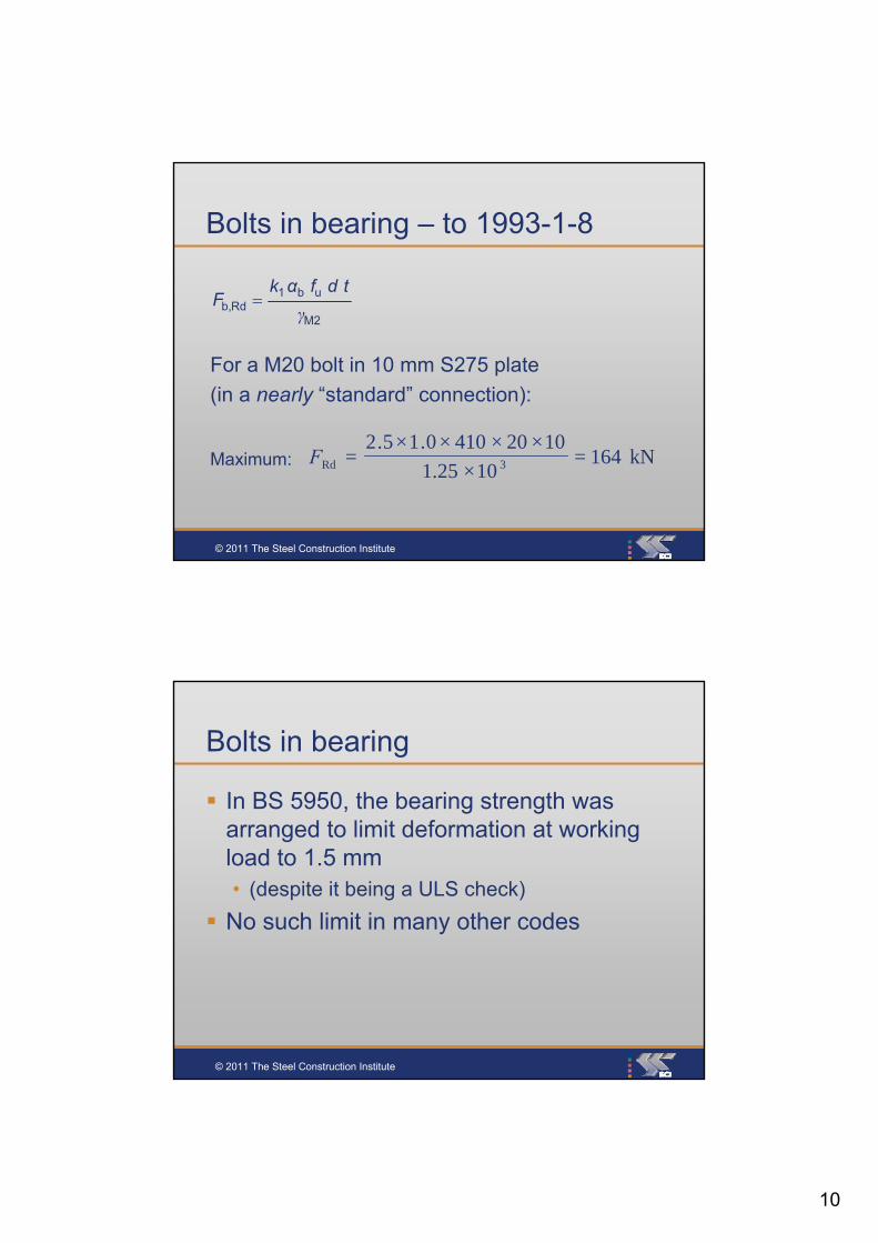
Bolts in bearing – to 1993-1-8
M2
ub1Rdb, γ
tdfαkF
kN112=10×1.25
10×20×410×81.0×11.2= 3RdF
For a M20 bolt in 10 mm S275 plate
(in a “standard” connection):
10
© 2011 The Steel Construction Institute
Bolts in bearing – to 1993-1-8
M2
ub1Rdb, γ
tdfαkF
For a M20 bolt in 10 mm S275 plate
(in a nearly “standard” connection):
kN164=10×1.25
10×20×410×0.1×5.2= 3RdFMaximum:
© 2011 The Steel Construction Institute
Bolts in bearing
In BS 5950, the bearing strength was arranged to limit deformation at working load to 1.5 mm• (despite it being a ULS check)
No such limit in many other codes

11
© 2011 The Steel Construction Institute
NA Note to the M table:
“in certain circumstances deformation at serviceability might control and a M2 = 1.5 would be more appropriate”
kN101.5
..23Rd 137
1020410015
FMaximum:
© 2011 The Steel Construction Institute
Bolt groups
If the shear resistance is greater than anybearing resistances, then the connection resistance = bearing
Else, the connection resistance
= n × minimum resistance
(Cl 3.7)
12
© 2011 The Steel Construction Institute
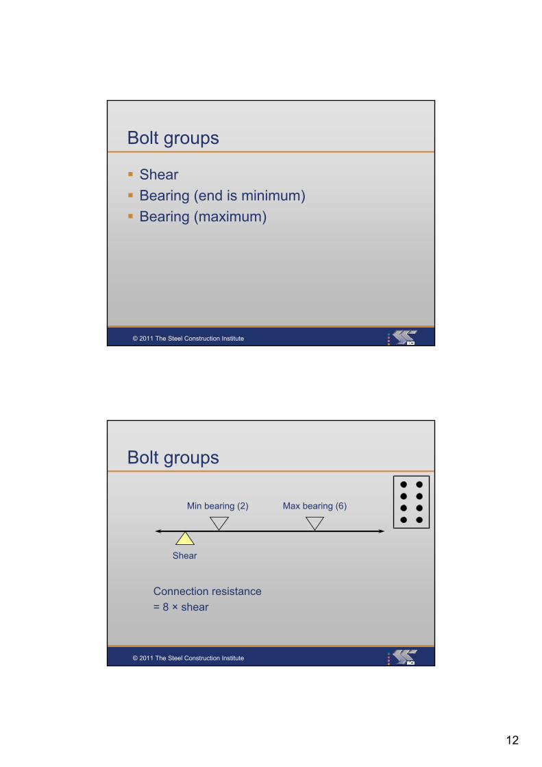
Bolt groups
Shear
Bearing (end is minimum)
Bearing (maximum)
© 2011 The Steel Construction Institute
Bolt groups
Min bearing (2) Max bearing (6)
Shear
Connection resistance
= 8 × shear
13
© 2011 The Steel Construction Institute
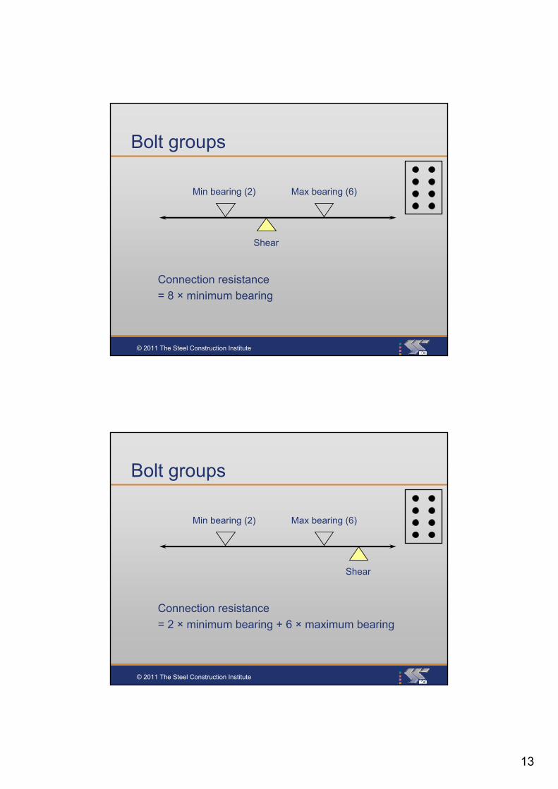
Bolt groups
Min bearing (2) Max bearing (6)
Shear
Connection resistance
= 8 × minimum bearing
© 2011 The Steel Construction Institute
Bolt groups
Min bearing (2) Max bearing (6)
Shear
Connection resistance
= 2 × minimum bearing + 6 × maximum bearing

14
© 2011 The Steel Construction Institute
Bolts in tension
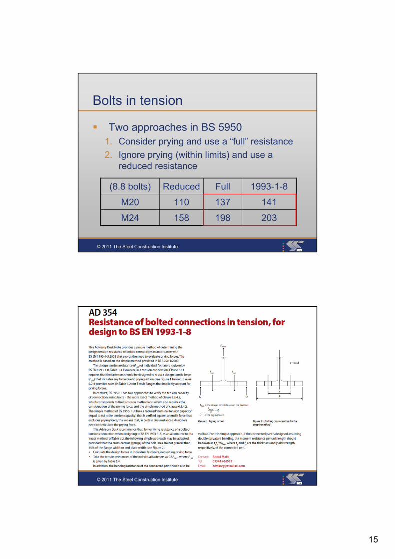
Two approaches in BS 59501. Consider prying and use a “full” resistance
2. Ignore prying (within limits) and use a reduced resistance
198158M24
137110M20
FullReduced(8.8 bolts)
© 2011 The Steel Construction Institute
Bolts in tension
M2
sub2Rdt, γ
AfkF
k2 = 0.9
k2 = 0.63 for a countersunk bolt
kN1411.25
2458000.9Rdt,
F
137 kN in BS 5950when prying calculated
M20, 8.8
15
© 2011 The Steel Construction Institute
Bolts in tension
Two approaches in BS 59501. Consider prying and use a “full” resistance
2. Ignore prying (within limits) and use a reduced resistance
203
141
1993-1-8
198158M24
137110M20
FullReduced(8.8 bolts)
© 2011 The Steel Construction Institute

16
© 2011 The Steel Construction Institute
Bolts in tension
(8.8 bolts)
162
113
198
137
203158M24
141110M20
FullReduced at 0.8kN
© 2011 The Steel Construction Institute
Welds
A directional method
A simplified method – Cl.4.5.3.3
Fw,Ed Fw,Rd
Fw,Rd = fvw.d a (a is the throat)
fvw.d = fu is the ultimate tensile strengthof the weaker part
w depends on steel grade:= 0.85 for S 275= 0.9 for S 355
M2w
u
3
β
f
17
© 2011 The Steel Construction Institute
Welds
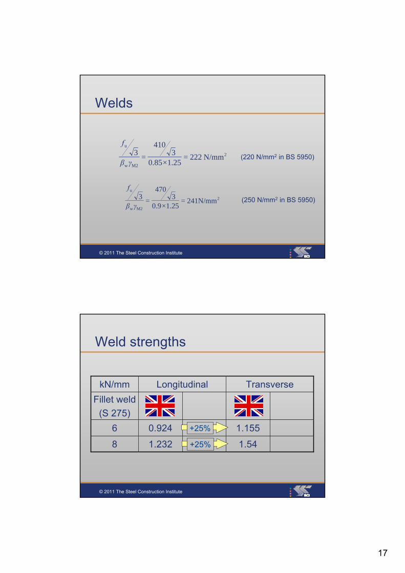
2
M2w
u
N/mm 222=1.25×0.85
3410
=3
γβ
f
(220 N/mm2 in BS 5950)
2
M2w
u
241N/mm=1.25×0.9
3470
=3
γβ
f
(250 N/mm2 in BS 5950)
© 2011 The Steel Construction Institute
Weld strengths
Fillet weld
(S 275)
1.54
1.155
1.2328
0.9246
TransverseLongitudinalkN/mm
+25%
+25%

18
© 2011 The Steel Construction Institute
Weld strengths
Fillet weld
(S 275)
1.25
0.94
1.538
1.156
TransverseLongitudinalkN/mm
+22%
+22%
© 2011 The Steel Construction Institute
Weld strengths
Fillet weld
(S 275)
1.25
0.94
1.54
1.155
1.531.2328
1.150.9246
TransverseLongitudinalkN/mm

19
© 2011 The Steel Construction Institute
Also in BS EN 1993-1-8
Limiting edge, end, pitch etc
Bolts through packing
Long joints
Slip-resistant connections (HSFGs)• Non-slip at SLS
• Non-slip at ULS
Block tearing (block shear)
Pins
© 2011 The Steel Construction Institute
An intermediate summary
Bolts in shear are nearly identical
Bolts in tension are nearly identical
Bolts in bearing – will not often govern
Welds are nearly identical
Plates in shear are almost identical
20
© 2011 The Steel Construction Institute
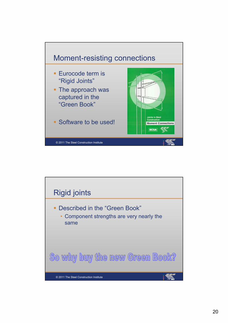
Moment-resisting connections
Eurocode term is “Rigid Joints”
The approach was captured in the “Green Book”
Software to be used!
© 2011 The Steel Construction Institute
Rigid joints
Described in the “Green Book”• Component strengths are very nearly the
same

21
© 2011 The Steel Construction Institute
Joint classification:
All connections require classification before using them:• by stiffness (elastic design)
• or by strength (plastic design)
• … or both
© 2011 The Steel Construction Institute
Joint classes
Nominally pinned
Rigid
Semi-rigid
22
© 2011 The Steel Construction Institute
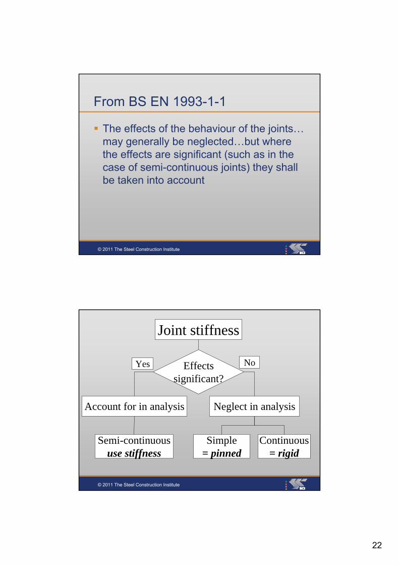
From BS EN 1993-1-1
The effects of the behaviour of the joints…may generally be neglected…but where the effects are significant (such as in the case of semi-continuous joints) they shall be taken into account
© 2011 The Steel Construction Institute
Joint stiffness
Neglect in analysisAccount for in analysis
Simple= pinned
Semi-continuoususe stiffness
Continuous= rigid
Effectssignificant?
Yes No

23
© 2011 The Steel Construction Institute
Classification by Strength
Nominally pinned• Accept the rotations – must be ductile
• A capacity less than 25% of full strength
Full strength• A resistance greater than that of the
connected members
© 2011 The Steel Construction Institute
Classification by stiffness
• Nominally pinned?
• Semi-rigid?
• Rigid
Pages of calculations
24
© 2011 The Steel Construction Institute
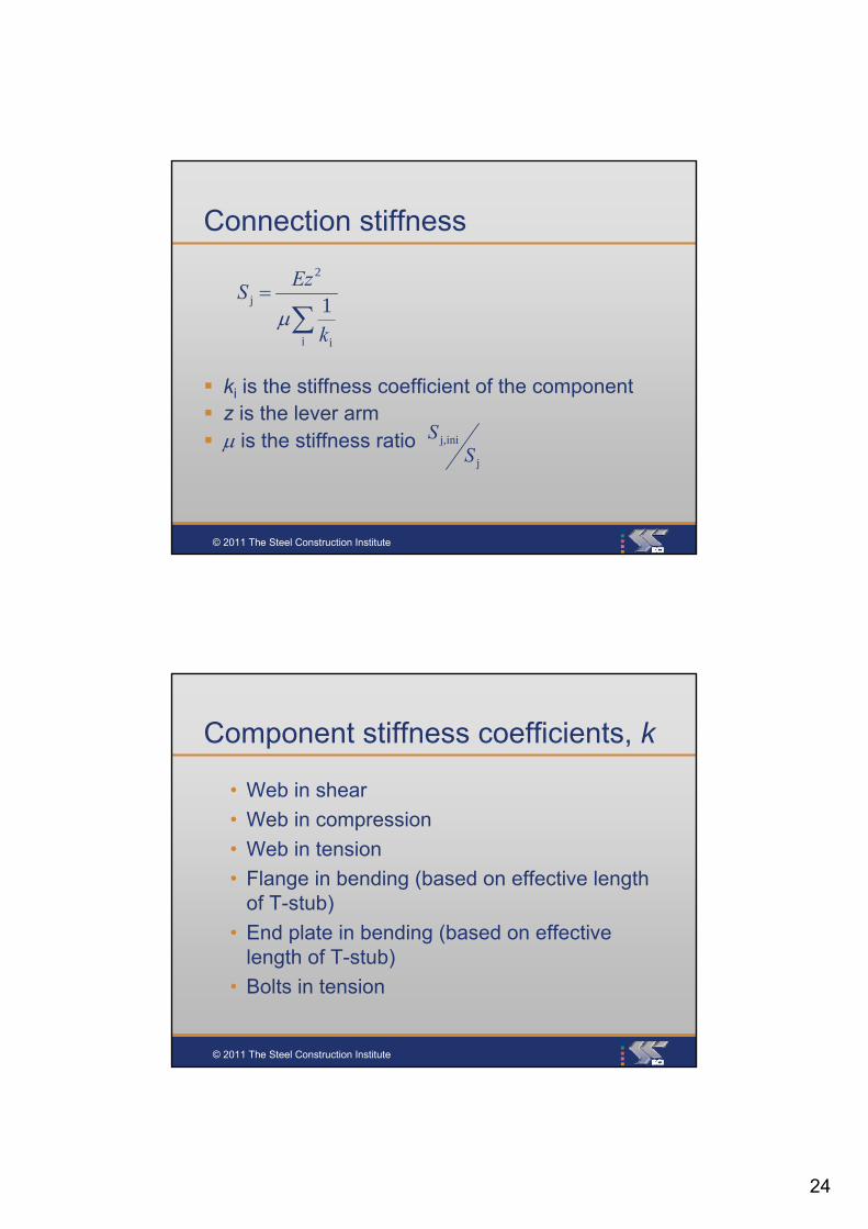
Connection stiffness
ki is the stiffness coefficient of the component z is the lever arm is the stiffness ratio
i i
2
j 1k
EzS
j
inij,
SS
© 2011 The Steel Construction Institute
Component stiffness coefficients, k
• Web in shear
• Web in compression
• Web in tension
• Flange in bending (based on effective length of T-stub)
• End plate in bending (based on effective length of T-stub)
• Bolts in tension

25
© 2011 The Steel Construction Institute
Moment-rotation curves
2/3
© 2011 The Steel Construction Institute
Moment-rotation curves
26
© 2011 The Steel Construction Institute
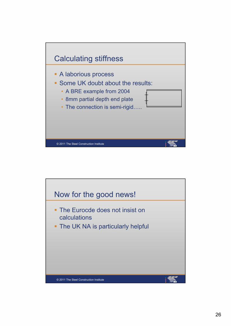
Calculating stiffness
A laborious process
Some UK doubt about the results:• A BRE example from 2004
• 8mm partial depth end plate
• The connection is semi-rigid…..
© 2011 The Steel Construction Institute
Now for the good news!
The Eurocde does not insist on calculations
The UK NA is particularly helpful
27
© 2011 The Steel Construction Institute
Joint classification
A joint may be classified on the basis of experimental evidence, experience of previous satisfactory performance in similar cases or by calculations based on test evidence
© 2011 The Steel Construction Institute
UK National Annex
Connections designed in accordance with the principles in:
… the Green Book on Simple Connections –…are pinned
… the Green Book on Moment connections –…are continuous

28
© 2011 The Steel Construction Institute
Where to be concerned
Outside the UK• quels sont les livres verts?
• was sind die grüne Bücher?
• czym są zielone książki?
© 2011 The Steel Construction Institute
Where to be concerned
If you use a non-standard connection• Outside the Green Books
• With no previous satisfactory experience
• ….pinned connections carrying large tying forces?
• A golden opportunity for disputes

29
© 2011 The Steel Construction Institute
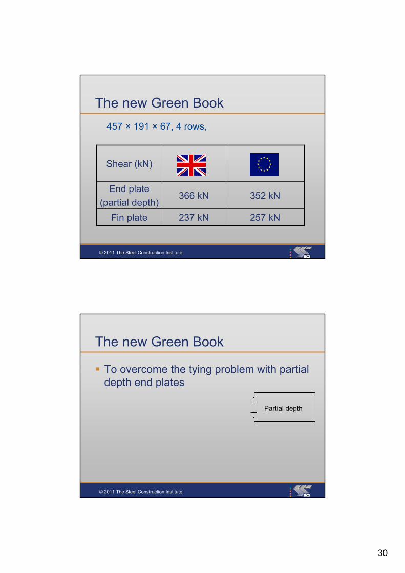
The new Green Book
Fin plate
End plate
(partial depth)
Shear (kN)
237 kN
366 kN
457 × 191 × 67, 4 rows,
© 2011 The Steel Construction Institute
The new Green Book
Fin plate
End plate
(partial depth)
Shear (kN)
237 kN
366 kN
457 × 191 × 67, 4 rows,
30
© 2011 The Steel Construction Institute
The new Green Book
Fin plate
End plate
(partial depth)
Shear (kN)
257 kN237 kN
352 kN366 kN
457 × 191 × 67, 4 rows,
© 2011 The Steel Construction Institute
The new Green Book
To overcome the tying problem with partial depth end plates
Partial depth

31
© 2011 The Steel Construction Institute
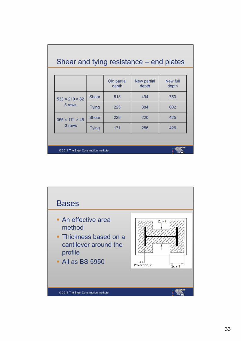
Shear and tying resistance – end plates
171
229
225
513
Old partial depth
Shear356 × 171 × 45
3 rows Tying
Tying
Shear533 × 210 × 82
5 rows
New full depth
New partial depth
© 2011 The Steel Construction Institute
The new Green Book
To overcome the tying problem
A brand new detail:• Welded to both flanges
Increases the tying force considerably
• Relatively thin platesClassified as “pinned”
Partial depth
Full depth

32
© 2011 The Steel Construction Institute
Shear and tying resistance – end plates
171
229
225
513
Old partial depth
220Shear356 × 171 × 45
3 rows Tying
Tying
Shear
286
384
494533 × 210 × 82
5 rows
New full depth
New partial depth
© 2011 The Steel Construction Institute
Shear and tying resistance – end plates
171
229
225
513
Old partial depth
220Shear356 × 171 × 45
3 rows Tying
Tying
Shear
286
384
494533 × 210 × 82
5 rows
New full depth
New partial depth
33
© 2011 The Steel Construction Institute
Shear and tying resistance – end plates
171
229
225
513
Old partial depth
425220Shear356 × 171 × 45
3 rows Tying
Tying
Shear
426286
602384
753494533 × 210 × 82
5 rows
New full depth
New partial depth
© 2011 The Steel Construction Institute
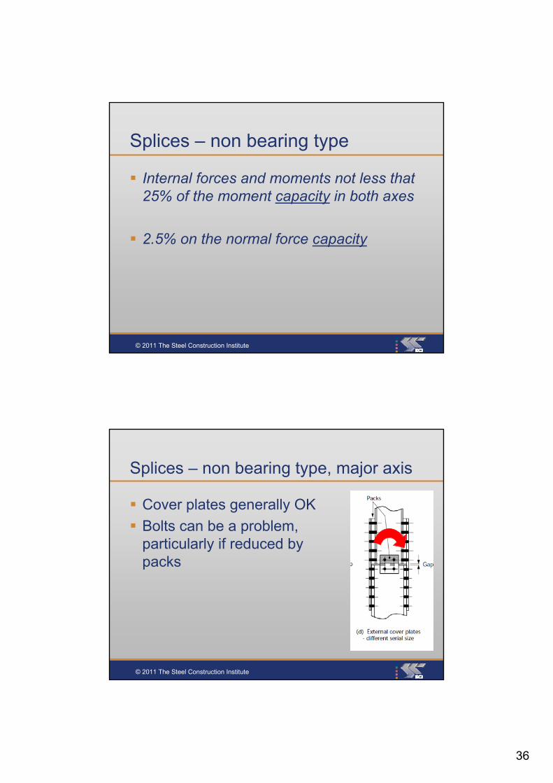
Bases
An effective area method
Thickness based on a cantilever around the profile
All as BS 5950

34
© 2011 The Steel Construction Institute
Splices
No change in details, but onerous “minimum” strength requirements
© 2011 The Steel Construction Institute
Splices – bearing type
Splice material should be provided to transmit 25% of the maximum compressive force in the column

35
© 2011 The Steel Construction Institute
Splices – bearing type, cover plates
Not a problem, usually
Cover plate cross section will be about 40% of capacity(much more than force)
Can be a modest problem in bolts – shear resistance reduced by packs
© 2011 The Steel Construction Institute
Splices – bearing type, cap / base
How to apply the rule, if at all.
36
© 2011 The Steel Construction Institute
Splices – non bearing type
Internal forces and moments not less that 25% of the moment capacity in both axes
2.5% on the normal force capacity
© 2011 The Steel Construction Institute
Splices – non bearing type, major axis
Cover plates generally OK
Bolts can be a problem, particularly if reduced by packs

37
© 2011 The Steel Construction Institute
Splices – non bearing type, minor axis
Cover plates generally OK• (based on cross section
resistance)
Bolt shear can often be a problem, particularly if reduced by packs
Bearing can be a problem
© 2011 The Steel Construction Institute
Splices – non bearing
More significant issues with chunky, higher grade columns
38
© 2011 The Steel Construction Institute
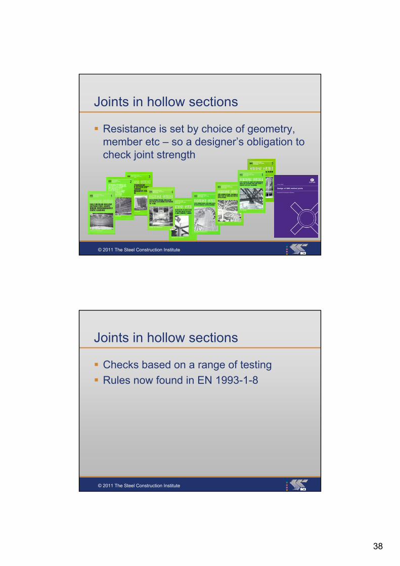
Joints in hollow sections
Resistance is set by choice of geometry, member etc – so a designer’s obligation to check joint strength
© 2011 The Steel Construction Institute
Joints in hollow sections
Checks based on a range of testing
Rules now found in EN 1993-1-8

39
© 2011 The Steel Construction Institute
© 2011 The Steel Construction Institute

40
© 2011 The Steel Construction Institute
© 2011 The Steel Construction Institute

41
© 2011 The Steel Construction Institute
Conclusions (1)
Components – as expected very nearly identical resistances
Connection resistances are nearly identical
So can a frame designed to EC3 have connections designed to BS 5950, if the ULS loads are given?• Yes for orthodox connections – simple or rigid
© 2011 The Steel Construction Institute
Conclusions (2)
Section classification is new in the UK• Stick with known details
Green Book “Simple” connections –summer 2011• With new, full depth end plates
Green Book “Rigid” connections – summer 2012

42
© 2011 The Steel Construction Institute
Personal view
They are inevitable
We can manage to design
SCI is the leading, independent provider of technical expertise and disseminator of best practice to the steel construction sector. We work in partnership with clients, members and industry peers to help build businesses and provide competitive advantage through the commercial application of our knowledge. We are committed to offering and promoting sustainable and environmentally responsible solutions.
Related Documents