CONNECTICUT DEPARTMENT OF TRANSPORTATION BUREAU OF ENGINEERING AND CONSTRUCTION OFFICE OF CONSTRUCTION DIVISION OF MATERIALS TESTING Quality Assurance (QA) Program for Materials Acceptance and Assurance Testing Policies and Procedures January 2017 Prepared by Materials Testing Staff

Welcome message from author
This document is posted to help you gain knowledge. Please leave a comment to let me know what you think about it! Share it to your friends and learn new things together.
Transcript
CONNECTICUT DEPARTMENT OF TRANSPORTATION
BUREAU OF ENGINEERING AND
CONSTRUCTION
OFFICE OF CONSTRUCTION
DIVISION OF MATERIALS TESTING
Quality Assurance (QA) Program for Materials Acceptance and Assurance Testing Policies and Procedures
January 2017 Prepared by Materials Testing Staff
ii
Chapter 1 – Purpose ................................................................................................................................... 1
Chapter 2 – Division of Materials Testing Overview ............................................................................... 2
ORGANIZATIONAL CHART ................................................................................................................ 3
Project Support & Portland Cement Concrete (PS) Section ..................................................... 4
District Laboratories’ Operations ...................................................................................................................... 4
Physical Testing Lab/Cement ........................................................................................................................... 4
Precast Concrete Fabrication ............................................................................................................................ 5
Hot Mix Asphalt and Final Material Certification (HMA) Section ............................................. 5
Bituminous Materials Laboratory ...................................................................................................................... 5
Final Materials Certification and File Retention .............................................................................................. 5
HMA Density and Verification Lab .................................................................................................................... 5
HMA Plant Acceptance ...................................................................................................................................... 5
Independent Assurance and Field Inspection (IA) Section ....................................................... 6
HMA Plant and Core Assurance ....................................................................................................................... 6
HMA Plant Inspection ......................................................................................................................................... 7
Material Certification and Certified Test Reports. .......................................................................................... 7
SiteManager ........................................................................................................................................................ 7
Structural Steel Fabrication Plant/Field Operations ....................................................................................... 7
Consultants/Fabrication Records ..................................................................................................................... 7
Chapter 3 – Material Code Definitions ...................................................................................................... 8
Paint/Coatings/Markings ................................................................................................................................. 8
Landscaping Materials .................................................................................................................................... 9
Precast Concrete Drainage Materials ........................................................................................................ 10
Pipe ..................................................................................................................................................................... 11
Steel Reinforcement ....................................................................................................................................... 12
Portland Cement Concrete ........................................................................................................................... 12
Prestressed/Post-Tensioned/Concrete Members ................................................................................... 12
Portland Cement/Chemical Anchor............................................................................................................ 13
Joint Materials ................................................................................................................................................. 13
Brick and Block ............................................................................................................................................... 14
Metal Castings ................................................................................................................................................. 14
Fences ............................................................................................................................................................... 14
Railings .............................................................................................................................................................. 15
Structural Anchors & Bearings ................................................................................................................... 16
Structural Steel ................................................................................................................................................ 17
Highway Lighting & Traffic Control............................................................................................................ 17
Hot Mix Asphalt Materials ............................................................................................................................. 18
Aggregates ....................................................................................................................................................... 20
Chapter 4 – Materials Evaluation and Testing Procedures .................................................................. 22
Materials Evaluation .......................................................................................................................... 22
Materials Testing Procedures ......................................................................................................... 22
Sampling Materials for Test ......................................................................................................................... 22
Aggregates ....................................................................................................................................................... 23
Precast Concrete Production Facility Inspection ...................................................................... 23
Reinforced Concrete Pipe ............................................................................................................................ 23
Precast Concrete Drainage Items ............................................................................................................... 25
PRECAST/PRESTRESSED CONCRETE (STRUCTURAL)......................................................... 27
PORTLAND CEMENT CONCRETE (ALL) ...................................................................................... 29
Concrete Batch Plants and Delivery Vehicles ......................................................................................... 29
iii
Compressive Strength of Cylindrical Concrete Specimens ................................................................ 29
Mass, Yield, and Air Content (Gravimetric) of PC Concrete ............................................................... 29
Assurance Report (DMT Only): MAT-224, or MAT-225, and MAT-222 ............................................... 29
Admixtures ....................................................................................................................................................... 29
Structural Steel and Welding Shop Inspection .......................................................................... 29
HOT MIX ASPHALT (BITUMINOUS CONCRETE/SUPERPAVE) .............................................. 30
Annual Qualification of Hot Mix Asphalt Plants ......................................................................... 30
Sampling HMA Mixtures ................................................................................................................................ 30
Binder Content by Ignition Method ............................................................................................................ 30
Correlation Between Production Pull and Binder Content by Ignition Method .............................. 30
Mechanical Analysis of Extracted Aggregate ......................................................................................... 31
Degree of Particle Coating of HMA Mixtures ........................................................................................... 31
Bulk Specific Gravity of Compacted HMA Mixtures .............................................................................. 31
Volumetric Calculations of VMA ................................................................................................................. 31
Preparation of Gyratory Specimens .......................................................................................................... 31
Maximum Specific Gravity of HMA Paving Mixtures ............................................................................. 32
Status of New Mixes, Existing Mixes From Previous Year’s Production ......................................... 32
Mix Design / Job Mix Formula(JMF) Submittal and Change Procedure ........................................... 32
HMA Verification Testing Procedures ....................................................................................................... 33
Resistance of Compacted HMA to Moisture Induced Damage ........................................................... 36
Volumetric and Specific Gravity Using Gyratory Compactor ............................................................. 36
Performance Graded Asphalt Binder (PGAB) ......................................................................................... 36
DENSITY OF SOIL AND SOIL - AGGREGATES .......................................................................... 36
DENSITY OF IN-PLACE ASPHALT PAVEMENT BY THE CORE METHOD ........................... 36
Chapter 5 – AMRL Document................................................................................................................... 37
Chapter 6 – Independent Assessment/Verification Program ............................................................... 38
Chapter 7 – Minimum Schedule for Acceptance Testing (Non-NHS) .................................................. 40
Chapter 8 – Minimum Schedule for Acceptance Testing ...................................................................... 41
Chapter 9 – Minimum Schedule for Assurance Testing ....................................................................... 53
Appendix A – Reporting Forms .............................................................................................................. A1
Appendix B – Final Materials Certification ............................................................................................ B1
Appendix C – Sample Scope of Work for Third-Party Testing Agency .............................................. C1
Appendix D – Active Material Codes ...................................................................................................... D1
Appendix E – Certification of Portland Cement Program ..................................................................... E1
Appendix F – Connecticut Reference File Specifications .................................................................... F1
Appendix G – Standard Operating Procedures. ................................................................................... G1
Index .......................................................................................................................................................... H1
1
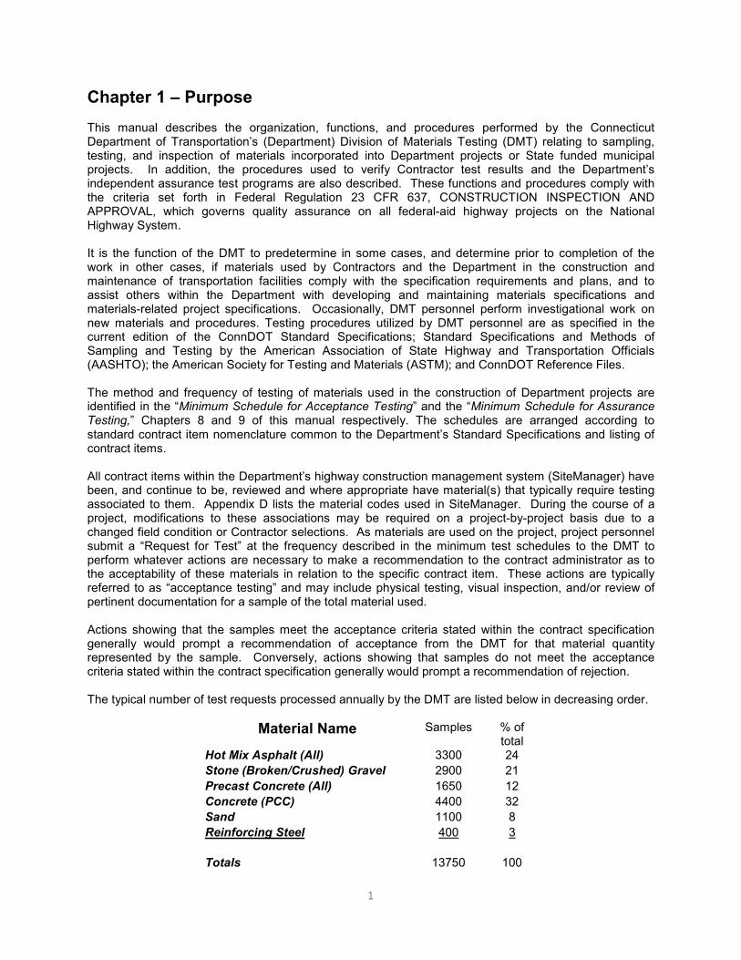
Chapter 1 – Purpose This manual describes the organization, functions, and procedures performed by the Connecticut Department of Transportation’s (Department) Division of Materials Testing (DMT) relating to sampling, testing, and inspection of materials incorporated into Department projects or State funded municipal projects. In addition, the procedures used to verify Contractor test results and the Department’s independent assurance test programs are also described. These functions and procedures comply with the criteria set forth in Federal Regulation 23 CFR 637, CONSTRUCTION INSPECTION AND APPROVAL, which governs quality assurance on all federal-aid highway projects on the National Highway System. It is the function of the DMT to predetermine in some cases, and determine prior to completion of the work in other cases, if materials used by Contractors and the Department in the construction and maintenance of transportation facilities comply with the specification requirements and plans, and to assist others within the Department with developing and maintaining materials specifications and materials-related project specifications. Occasionally, DMT personnel perform investigational work on new materials and procedures. Testing procedures utilized by DMT personnel are as specified in the current edition of the ConnDOT Standard Specifications; Standard Specifications and Methods of Sampling and Testing by the American Association of State Highway and Transportation Officials (AASHTO); the American Society for Testing and Materials (ASTM); and ConnDOT Reference Files. The method and frequency of testing of materials used in the construction of Department projects are identified in the “Minimum Schedule for Acceptance Testing” and the “Minimum Schedule for Assurance Testing,” Chapters 8 and 9 of this manual respectively. The schedules are arranged according to standard contract item nomenclature common to the Department’s Standard Specifications and listing of contract items. All contract items within the Department’s highway construction management system (SiteManager) have been, and continue to be, reviewed and where appropriate have material(s) that typically require testing associated to them. Appendix D lists the material codes used in SiteManager. During the course of a project, modifications to these associations may be required on a project-by-project basis due to a changed field condition or Contractor selections. As materials are used on the project, project personnel submit a “Request for Test” at the frequency described in the minimum test schedules to the DMT to perform whatever actions are necessary to make a recommendation to the contract administrator as to the acceptability of these materials in relation to the specific contract item. These actions are typically referred to as “acceptance testing” and may include physical testing, visual inspection, and/or review of pertinent documentation for a sample of the total material used. Actions showing that the samples meet the acceptance criteria stated within the contract specification generally would prompt a recommendation of acceptance from the DMT for that material quantity represented by the sample. Conversely, actions showing that samples do not meet the acceptance criteria stated within the contract specification generally would prompt a recommendation of rejection. The typical number of test requests processed annually by the DMT are listed below in decreasing order.
Material Name Samples % of total
Hot Mix Asphalt (All) 3300 24
Stone (Broken/Crushed) Gravel 2900 21
Precast Concrete (All) 1650 12
Concrete (PCC) 4400 32
Sand 1100 8
Reinforcing Steel 400 3
Totals 13750 100
2
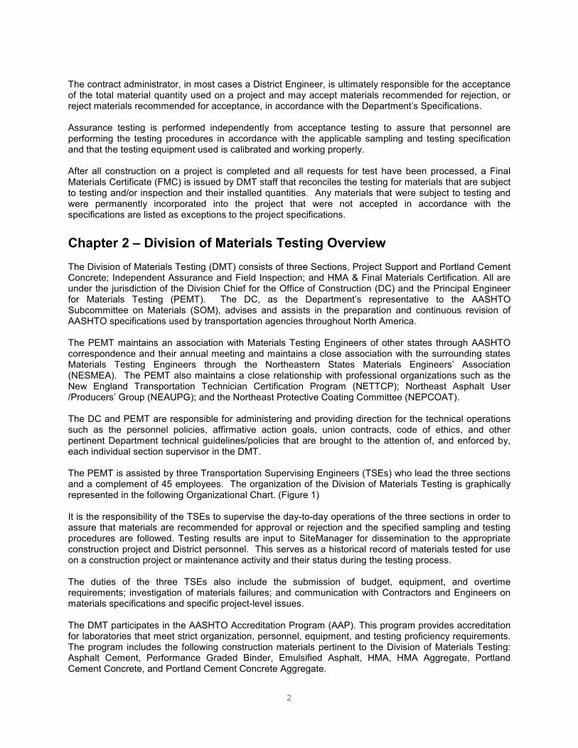
The contract administrator, in most cases a District Engineer, is ultimately responsible for the acceptance of the total material quantity used on a project and may accept materials recommended for rejection, or reject materials recommended for acceptance, in accordance with the Department’s Specifications. Assurance testing is performed independently from acceptance testing to assure that personnel are performing the testing procedures in accordance with the applicable sampling and testing specification and that the testing equipment used is calibrated and working properly. After all construction on a project is completed and all requests for test have been processed, a Final Materials Certificate (FMC) is issued by DMT staff that reconciles the testing for materials that are subject to testing and/or inspection and their installed quantities. Any materials that were subject to testing and were permanently incorporated into the project that were not accepted in accordance with the specifications are listed as exceptions to the project specifications.
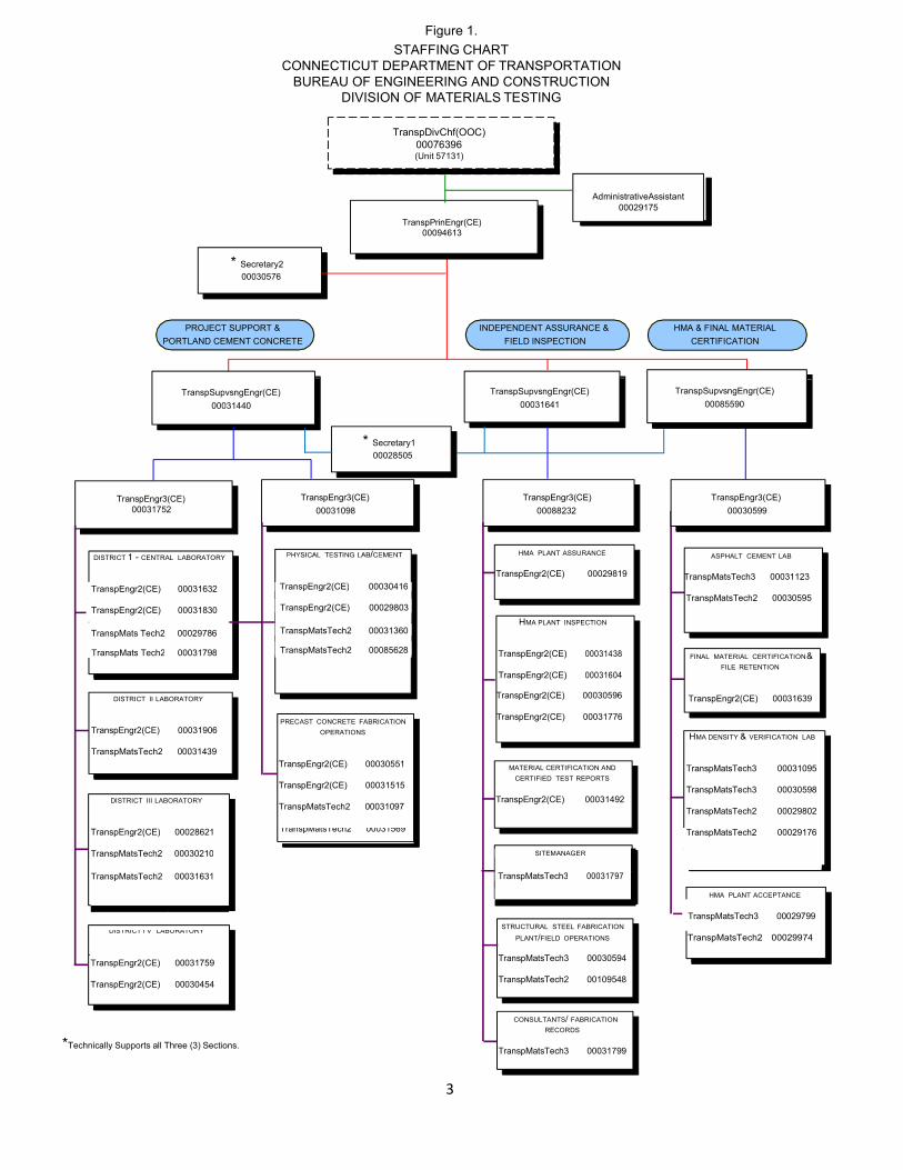
Chapter 2 – Division of Materials Testing Overview The Division of Materials Testing (DMT) consists of three Sections, Project Support and Portland Cement Concrete; Independent Assurance and Field Inspection; and HMA & Final Materials Certification. All are under the jurisdiction of the Division Chief for the Office of Construction (DC) and the Principal Engineer for Materials Testing (PEMT). The DC, as the Department’s representative to the AASHTO Subcommittee on Materials (SOM), advises and assists in the preparation and continuous revision of AASHTO specifications used by transportation agencies throughout North America. The PEMT maintains an association with Materials Testing Engineers of other states through AASHTO correspondence and their annual meeting and maintains a close association with the surrounding states Materials Testing Engineers through the Northeastern States Materials Engineers’ Association (NESMEA). The PEMT also maintains a close relationship with professional organizations such as the New England Transportation Technician Certification Program (NETTCP); Northeast Asphalt User /Producers’ Group (NEAUPG); and the Northeast Protective Coating Committee (NEPCOAT). The DC and PEMT are responsible for administering and providing direction for the technical operations such as the personnel policies, affirmative action goals, union contracts, code of ethics, and other pertinent Department technical guidelines/policies that are brought to the attention of, and enforced by, each individual section supervisor in the DMT. The PEMT is assisted by three Transportation Supervising Engineers (TSEs) who lead the three sections and a complement of 45 employees. The organization of the Division of Materials Testing is graphically represented in the following Organizational Chart. (Figure 1) It is the responsibility of the TSEs to supervise the day-to-day operations of the three sections in order to assure that materials are recommended for approval or rejection and the specified sampling and testing procedures are followed. Testing results are input to SiteManager for dissemination to the appropriate construction project and District personnel. This serves as a historical record of materials tested for use on a construction project or maintenance activity and their status during the testing process. The duties of the three TSEs also include the submission of budget, equipment, and overtime requirements; investigation of materials failures; and communication with Contractors and Engineers on materials specifications and specific project-level issues. The DMT participates in the AASHTO Accreditation Program (AAP). This program provides accreditation for laboratories that meet strict organization, personnel, equipment, and testing proficiency requirements. The program includes the following construction materials pertinent to the Division of Materials Testing: Asphalt Cement, Performance Graded Binder, Emulsified Asphalt, HMA, HMA Aggregate, Portland Cement Concrete, and Portland Cement Concrete Aggregate.
3
Figure 1.
STAFFING CHART
CONNECTICUT DEPARTMENT OF TRANSPORTATION
BUREAU OF ENGINEERING AND CONSTRUCTION
DIVISION OF MATERIALS TESTING
TranspDivChf(OOC)
00076396 (Unit 57131)
TranspPrinEngr(CE)
00094613
* Secretary2
00030576
PROJECT SUPPORT &
PORTLAND CEMENT CONCRETE
INDEPENDENT ASSURANCE &
FIELD INSPECTION
HMA & FINAL MATERIAL
CERTIFICATION
TranspSupvsngEngr(CE)
00031440
TranspSupvsngEngr(CE)
00031641
TranspSupvsngEngr(CE)
00085590
* Secretary1
00028505
TranspEngr3(CE)
00031752
TranspEngr3(CE)
00031098
TranspEngr3(CE)
00088232
TranspEngr3(CE)
00030599
DISTRICT 1 - CENTRAL LABORATORY
HMA PLANT ASSURANCE
TranspEngr2(CE) 00029819
ASPHALT CEMENT LAB
TranspMatsTech3 00031123
TranspMatsTech2 00030595
HMA PLANT INSPECTION
TranspEngr2(CE) 00031438
TranspEngr2(CE) 00031604
FINAL MATERIAL CERTIFICATION &
FILE RETENTION
DISTRICT II LABORATORY
TranspEngr2(CE) 00031906
TranspMatsTech2 00031439
DISTRICT III LABORATORY
PRECAST CONCRETE FABRICATION
OPERATIONS
TranspEngr2(CE) 00030551
TranspEngr2(CE) 00031515
TranspMatsTech2 00031097
TranspEngr2(CE) 00030596
TranspEngr2(CE) 00031776
MATERIAL CERTIFICATION AND
CERTIFIED TEST REPORTS
TranspEngr2(CE) 00031492
TranspEngr2(CE) 00031639
HMA DENSITY & VERIFICATION LAB
TranspMatsTech3 00031095
TranspMatsTech3 00030598
TranspMatsTech2 00029802
TranspEngr2(CE) 00028621
TranspMatsTech2 00031569
TranspMatsTech2 00029176
TranspMatsTech2 00030210
SITEMANAGER
TranspMatsTech2 00031631
TranspMatsTech3 00031797
HMA PLANT ACCEPTANCE
TranspMatsTech3 00029799
STRUCTURAL STEEL FABRICATION
DISTRICT I V LABORATORY PLANT/FIELD OPERATIONS TranspMatsTech2 00029974
.
TranspEngr2(CE) 00031759
TranspEngr2(CE) 00030454
TranspMatsTech3 00030594
TranspMatsTech2 00109548
*Technically Supports all Three (3) Sections.
CONSULTANTS/ FABRICATION
RECORDS
TranspMatsTech3 00031799
AdministrativeAssistant
00029175
TranspEngr2(CE) 00031632
TranspEngr2(CE) 00030416
TranspEngr2(CE) 00031830 TranspEngr2(CE) 00029803
TranspMats Tech2 00029786 TranspMatsTech2 00031360
TranspMats Tech2 00031798 TranspMatsTech2 00085628

4
Division of Materials Testing Overview (cont.) Project Support & Portland Cement Concrete (PS) Section The PS Section is primarily involved with the operation of the satellite laboratories in each of the outlying Districts and the testing and inspection of Portland cement concrete and precast and prestressed concrete members. In conjunction with those materials, this section also performs the physical testing of steel reinforcing material and other steel-related items. A large part of the service provided by this section is the support of the active construction projects and delivering some material samples to the Central Laboratory. Visits to the project sites are commonly done to retrieve all types of samples, assist project personnel in the submittal of all samples, and to assist in the testing of materials on site, or the assurance testing of PC concrete. The PS Section of the DMT is divided into three functional units: District Laboratories’ Operations, Physical Testing Lab/Cement, and Precast Concrete Fabrication Operations. District Laboratories’ Operations This unit oversees the operations of the three satellite District Laboratories located in each of the outlying three Districts and the Central Laboratory’s District 1 Lab in Rocky Hill. These laboratories are located in each District Office within the State to expedite the sampling and testing of common materials, such as aggregates. The unit is also responsible for maintaining an active independent assurance testing program for aggregates and concrete for the satellite District Laboratories consistent with that of the Central Laboratory. The satellite District Laboratories are primarily assigned materials sampling and testing for projects within the District in which they are located. The principal duties of the satellite District Laboratories are as follows:
• Perform acceptance testing of fine and coarse aggregates including but not limited to gradation analysis, specific gravity, density, and unit weight.
• Determine laboratory maximum density of soils and processed aggregates.
• Inspect metal pipe and metal culvert ends at project sites.
• Inspect and sample transportation materials at quarries, gravel banks, Portland cement concrete plants, and other sources of supply for Department projects.
• Perform acceptance sampling and testing of fine and coarse aggregates.
• Observe assurance sampling and testing for aggregates and Portland cement concrete.
• Obtain samples and transport them to the Central Laboratory as needed.
• Inspect any new sources of materials.
• Assist Division of Purchasing regarding sampling and testing of road salts. The District 1 Lab located within the Central Laboratory facility performs the same operations as the satellite District Labs with the additional task of checking the satellite District Labs’ test results for aggregates using split samples and performing additional tests on fine and coarse aggregates such as soundness, resistance to degradation by abrasion and impact, specific gravity, absorption, unit weights, angularity, and elongation. Physical Testing Lab/Cement The responsibilities of the physical testing unit include the testing for compressive strengths of concrete cylinders, testing of drilled cores, properties of brick and block, the tensile strengths of several ferrous and nonferrous structural steel products, the Rockwell or Brinell hardness of structural steel products, the coating thickness of zinc and epoxy coated products, and evaluating weld coupons for welder certification testing. This subsection may also perform testing on new products and materials being evaluated by the Department.
5
Precast Concrete Fabrication This unit acts as a liaison with precast concrete producers and project personnel to schedule on-site inspections and resolve technical and administrative issues. Inspectors in this unit are responsible for the quality assurance of prefabricated concrete products. These products include reinforced concrete pipe, precast and prestressed concrete items. The overall duties of the individual inspectors are to monitor the fabricators compliance to their own Quality Control (QC) Plan on file with the Department. At varying frequencies, the inspectors also sample all component materials for compliance with the Department’s specifications; inspect the casting beds and forms to ensure dimensional conformance to the approved drawings; observe the concrete batching operation to ascertain conformance to an approved mix design; witness plastic concrete testing; observe the concrete placement and consolidation operation; witness the compression testing of specimens; inspect the finished product for conformance to dimensional tolerances and finished appearance; and maintain complete and accurate Department records for all phases of the work. Consultants under contract to the Department are used as needed to supplement DMT personnel to meet this responsibility. Hot Mix Asphalt and Final Material Certification (HMA) Section The HMA Section is divided into five functional units: Bituminous Materials Lab, Final Materials Certification and File Retention, HMA Density and Verification Lab, and HMA Plant Acceptance. Bituminous Materials Laboratory This unit is responsible for testing of various performance graded (PG) binders and other petroleum based products. HMA paving and associated products physically tested by this unit are PG Binders, emulsified asphalts and bituminous component materials used in Ultra-thin HMA. In addition, this unit reviews binder and emulsified asphalt suppliers QC Plans and other required documentation to maintain the supplier certification by AASHTO R 26 and AASHTO R 77.
Final Materials Certification and File Retention This unit is responsible for tracking material testing data on a project to ensure that all materials permanently incorporated into the project are tested/certified in sufficient quantity and that the results are acceptable or alternative acceptance criteria are met. Upon request from the District, a final materials certificate is provided for all completed projects stating the disposition of all materials incorporated into the project. If applicable, exceptions to the project specifications are listed individually on the certificate. Examples of this certification are in Appendix B. HMA Density and Verification Lab This unit is responsible for verifying that mix designs are in compliance with project specifications and for validating Contractor data used for acceptance. Comparison testing during the paving season is performed on test specimens that are fabricated by both Contractor or DMT staff. Test records are maintained for each mixture type produced by each vendor providing materials to the Department. The HMA Density and Verification unit also performs extraction and aggregate tests on samples; processes cores for payment adjustment; and investigates new mix designs, additives, and aggregate sources. HMA Plant Acceptance Staff in this unit are responsible for monitoring HMA producer QC testing at the plant used for acceptance on a project-by-project basis and processing the results for payment adjustment purposes. HMA mix designs are also reviewed by staff in this unit for compliance to the project specifications and monitors changes in materials sources and the resulting mix design changes during the paving season. During the winter months, staff review producer generated QC Plans to ensure that the current specification requirements are recognized and any revisions are acceptable to the Department.

6
Independent Assurance and Field Inspection (IA) Section The IA Section is divided into six units: HMA Plant Assurance, HMA Plant Inspection, Material Certification and Certified Test Reports, SiteManager, Structural Steel Fabrication Plant/Field Operations, and Consultants/Fabrication Records. The IA Section of the DMT is primarily responsible to assure that the testing being performed by Department and/or Contractor personnel for acceptance purposes is performed by qualified personnel in accordance with standard test procedures and that the equipment used is adequate and calibrated. This typically includes a review of personnel qualifications, calibration records, witnessing test procedures first hand, and performing verification testing. The schedule for IA inspection is as follows:
Test Acceptance Samples
Assurance Samples
T-168 Sampling Bituminous Mixtures
10
1 (Min 1 per Month per Technician
during Construction
Season)
R-47 Reducing Samples of HMA
T-308 Asphalt Content Ignition Oven
T-30 Sieve Analysis
T-312 Preparation of Gyratory Sample
T-166 Bulk Specific Gravity
T-209 Theoretical Maximum Specific Gravity
T-331 Standard Method of Test for Bulk Specific Gravity (Gmb) and Density of Compacted Hot Mix Asphalt (HMA) Using Automatic Vacuum Sealing Method
40 1
This section is also responsible for the day-to-day administration of a consultant contract for the testing of structural steel at various out-of-state fabricators, and other seasonal inspection needs within the State; the review and processing of the consultant inspection reports; the update and maintenance of the materials module of SiteManager and interacting with construction field inspectors to revise and maintain materials testing results for individual projects; and addressing building-related issues for all Department personnel within the facility. HMA Plant and Core Assurance This unit follows an independent process from that for acceptance testing to ensure that material sampling and testing at the HMA plants and the DMT HMA Density and Verification Lab is being done correctly. The process evaluates personnel sampling and testing material for compliance with established standard test procedures and evaluates the equipment used for acceptance testing for adequacy and calibration. The evaluation process generally involves witnessing personnel during the testing procedure and documenting what is observed on the “Report of Witness” (MAT-600) form. Test equipment is evaluated through calibration checks, testing split samples, or any combination of these methods. Split sample results that agree with acceptance tests within the limits of Table 2, Column C, will not require any further action. Results that fall outside the limits will require an investigation to determine the cause of the discrepancy and have it corrected. Any sampling or testing of material for IA purposes is done on a separate schedule and frequency using separate equipment. Personnel assigned to this unit will not test material for acceptance nor will the results of any assurance testing be used for acceptance purposes.

7
HMA Plant Inspection This unit is responsible for quality assurance of all HMA material used on construction and maintenance projects. This is accomplished through the inspection of HMA material at the plant. Approximately thirty source locations that provide HMA for State projects are inspected by personnel in the HMA Plant Inspection unit. All producers are required to have a field laboratory to provide a DMT inspector immediate access to test results to assure material meets the specification at the plant. In addition to the testing of HMA, the plant inspectors sample the binder; observe the production process; inspect fine and coarse aggregates; verify batch weights, mix temperatures, and appearance; and check plant machinery and hauling vehicles for specification compliance. Plant inspectors maintain test records at each field lab and complete all applicable DMT forms. The supervisor of this section is responsible for daily field supervision and observation of field technicians sampling and testing techniques; performing plant and field lab inspections; notifying producers of material problems; performing verification and assurance sampling and testing; training and reviewing procedures and specifications with the field personnel; serving as a liaison between material producers and project personnel to remedy material issues; and working closely with the HMA Plant Acceptance unit to carry out QA and investigative tasks. Material Certification and Certified Test Reports. This unit is responsible for the review of material certificates and certified test reports to determine if the documentation provides the information necessary to recommend acceptance of the material. Following the issuance of the Final Materials Certificate for a particular project, personnel in this unit also compile and review the project records in accordance with the Department’s record retention policies so that they can be transferred to the Department’s record storage facility in Newington. SiteManager Staff are responsible for updating and maintaining the materials module of the SiteManager Reporting System and interacting with construction field inspectors and DMT personnel to revise and maintain materials testing results for individual projects. Structural Steel Fabrication Plant/Field Operations This unit has the responsibility to assure that all materials and physical aspects of structural steel fabrication are in compliance with the applicable specifications. Duties of this unit include the review and approval of shop and field welding procedures; assistance to other Department personnel regarding welding techniques and procedures; on-site audits and review of field welding and in-state fabrication; testing and certification of Department approved welders; and any related duties as they apply to structural steel fabrication. Consultants/Fabrication Records DMT personnel monitor consultant contracts for structural steel fabrication inspection on a day-to-day basis. Personnel in this unit are also responsible for the review and processing of steel fabrication inspection reports and making technical recommendations to the TSE of the section.
8
Chapter 3 – Material Code Definitions Paint/Coatings/Markings 00001 ENAMEL PAINT (BLACK/BURNT ORANGE) Scope: All enamel paint Sampling and Procedure: None Specification / Report Form: Black, Reference File No. 25, Burnt Orange Reference File No. 104 / NA
00031 PAINT – PRIME COAT FOR STRUCTURAL STEEL 00032 (Interim), 00033 (Top), 00039 (Field) STRUCTURAL STEEL COATINGS Sampling: Samples of coatings are generally not required unless specified in the Special Provisions. Procedure: Fabricators of structural steel are responsible for making themselves aware of the entire coating specification for each individual project prior to starting the work. The DMT must be notified in advance of any coating work on structural steel for Department use. Field painting and touch-up work must conform to Standard Specifications, Article 6.03.03-38. Project personnel are responsible for submitting a MAT-100 when the material is delivered to the project site. Specification: As specified in a Special Provision or Standard Specifications, Section 6.03 and M.07.
00054 PAVEMENT MARKING PAINT, 15-MINUTE DRY, WHITE AND YELLOW Scope: White and yellow pavement marking paint Sampling: Two quart samples will be taken by the manufacturer for each Lot Number in accordance with ASTM D3925, and forwarded to the DMT by the manufacturer accompanied by a certified test report. Procedure: As listed in Specification(s) Specification/Report Form(s): Federal Specification Paint TT-P-1952, Reference File No. 207D and M.07 / MAT-236, MAT-237, or MAT-240.
00060 TRAFFIC PAINT, 3 MINUTE DRY, WHITE AND YELLOW Scope: White and yellow low-heated, fast-drying pavement marking paint Sampling: Two quart samples will be taken by the manufacturer for each Lot Number in accordance with ASTM D3925, and forwarded to the DMT by the manufacturer accompanied by a certified test report. Procedure: Same as 00054 Specification/Report Form: Federal Specification Paint TT-P-1952, Reference File No. 200I and Section M.07 / MAT-235, MAT-238, or MAT-239.
00064 PAINT EPOXY 00091 PAINT EPOXY PAVEMENT MARKINGS Scope: White and yellow epoxy resin pavement marking paint Sampling: Two quart samples will be taken by the manufacturer for each Lot Number in accordance with ASTM D3925, and forwarded to the DMT by the manufacturer accompanied by a certified test report. Once per calendar year, one quart sample of the hardener forwarded to the DMT by the manufacturer accompanied by a certified test report.
00097 & 03057 Sand Blasting 00097 SAND BLAST DEBRIS (Toxicity Test) 03057 SAND BLAST ABRASIVE Scope: Sandblast debris from bridge painting. Sent to third-party laboratory for testing. Sampling and Procedure: EPA Method 1311 Specification/Report Form: Connecticut DEEP Drinking Water Remediation Standards / NA

9
00206 Black Pavement Markings 00206 PREFORMED BLACK MARKING TAPE Scope: Rolled tape for pavement markings. Sampling and Procedure: None Specification/Report Form: M.07 / NA
00297 to 00303 Snow & Ice Control 00297 CALCIUM CHLORIDE (LIQUID) 00302 CALCIUM CHLORIDE Scope: Highway Maintenance use only. Sampling and Procedure: None Specification/Report Form: AASHTO M 144 / NA
00298 SODIUM CHLORIDE (INERTIAL BARRIERS) 00303 SODIUM CHLORIDE (ROCK SALT) Scope: All sodium chloride used for snow and ice control on highways; or for use in inertial barriers. Sampling: For snow and ice control AASHTO T 2, none for inertial barriers. Procedure: Sieve analysis, AASHTO T 27; chemical, ASTM E 534; moisture content, AASHTO T 265. Specification/Report Form: For snow and ice control, ConnDOT Reference File No. 139 / MAT-208. For inertial barriers, Standard Specifications, Section 18.07 (Materials Certificate) / NA.
00306 GLASS SPHERES (GLASS BEADS) NOTE: All other material codes for glass beads are inactive. Scope: Glass spheres (glass beads) for application on pavement markings. Sampling: One sample will be provided for each Lot Number and forwarded to the DMT by the manufacturer. Procedure: AASHTO M 247 Specification/Report Form: AASHTO M 247, Type 1 and 4 / MAT-228 or MAT-229
00327 WATER
Scope: For production of PCC and any other material or process. Sampling and Procedure: None for potable sources. For other sources, ASTM C 1602. Specification/Report Form: Standard Specifications, Article M.03.01-4 / MAT-230
Landscaping Materials 00496 FERTILIZER Scope: Fertilizer for use in turf establishment. Sampling: None. Procedure: Standard Specifications, M.13.03 Specification/Report Form: Standard Specifications, Article M.13.03 / NA
00497 SEED Scope: Mixtures to establish turf or grass. Sampling: None Procedure: Standard Specifications, Article M.13.04 Specification/Report Form: Standard Specifications, Article M.13.04 / NA
00510 PEAT Scope: Commercially package peat from sedge, sphagnum or reed sources used on planting soil. Sampling: None - visual inspection by project personnel. Specification/report Form: Standard Specification, Article M.13.07 / NA
10
00511 LIMESTONE Scope: Agricultural ground dolomitic limestone used to increase pH on topsoils. Sampling: None Specification/Report Form: Standard Specification, Article M.13.02/ NA
00515 WOOD CHIP MULCH
00534 WOOD MULCH Scope: To establish quick germinating vegetation and/or prevent erosion. Sampling: None - visual inspection by project personnel. Specification/Report Form: Standard Specifications, Article M.13.05 / NA
00514 MULCH (HAY) 04776 BALED HAY
Scope: Used for turf establishment or sedimentation control. Sampling: None - visual inspection by project personnel. Specification/Report Form: Standard Specifications, Article M.13.05 (Mulch) or Section 2.18 (Sedimentation Control) / NA.
00518 SOD Scope: Sod used for the immediate establishment of a grass surface. Sampling: None - visual inspection by project personnel. Procedure: Project personnel contact Landscape Design Unit Specification/Report Form: Standard Specifications, Article M.13.08/ NA
00536 PLANT MATERIALS 07547 TREE Scope: All living plant materials are to be inspected by staff from the Department’s Landscape Design Unit. A MAT-100 is NOT required. Initial contact and follow up is the responsibility of project staff. Sampling: None - visual inspection by Landscape Design personnel. Procedure: Project staff contact Landscape Design Unit Specification/Report Form: Standard Specifications, Article M.13.07/ NA
00542 TOP SOIL Scope: Cut and fill material taken from the project site and used on the project site. Sampling: None - visual inspection by project personnel. Specification/Report Form: Standard Specifications, Article M.13.01 / NA
00542X TOP SOIL 00542P PLANTING SOIL Scope: Soil brought from off the project site for use under items 0949XXX furnishing and planting trees. Sampling: None. Materials Certificate and Certified Test Report submitted with MAT-100. Specification/Report Form: Standard Specifications, Article M.13.01 / NA
Precast Concrete Drainage Materials 00699, 1700, 1708 Reinforced Concrete Pipe 00699 REINFORCED CONCRETE PIPE 01700 PLAIN AND PERFORATED CONCRETE DRAIN PIPE 01708 PIPE – FOR UNDERDRAIN or OUTLET Scope: Plain and perforated concrete drain pipe. Sampling: Each size and type of pipe is subject to 3-edge bearing and absorption tests each spring. Procedure: AASHTO M 170 and AASHTO T 280. Specification/Report Form: Standard Specifications, Article M.08.01-7 / MAT-314
11
Precast Units For Drainage Structures
00823 to 01650 Precast Concrete Drainage & Misc. Refer to Appendix D for material codes Scope: Precast concrete units to be used in the construction of drainage structures. Precast units shall include, but not be limited to, products such as box culverts, catch basins, drop inlet and manhole tops, riser sections, sumps and other appurtenances. The recommendation for acceptance of precast units is based on the manufacturer's certification that the units conform to the project specifications. Ultimate acceptance of the material should be based on receipt of the manufacturer’s certification and a visual inspection by project personnel following delivery.
Pipe 01940 to 2650 PIPE (Metal, Iron, Poly, PVC)
01940 PIPE – CCM, Fittings & Accessories 01949 PIPE – COATED CORRUGATED METAL Scope: The field inspection of metal and aluminum pipe and structural plate pipe and pipe arches. Sampling: Depending on the size of the shipment, one or two representative pieces of metal pipe, bands, and accessories are selected by DMT and inspection personnel for testing. Procedure: Procedures and measurements are shown in the “Field Inspection of Metal and Aluminum Pipe” procedure in Appendix G. Materials Certificates and Certified Test Reports are also required. Report Form: MAT-200, MAT-201, MAT-202, MAT-203, or MAT-204.
02501 DUCTILE IRON PIPE 02510 DUCTILE IRON PIPE FITTINGS & ACCESSORIES 02724 PIPE- STEEL & FITTINGS & ACCESSORIES
Scope: This section covers welded and seamless steel pipe. Sampling: ASTM A 53 and as supplemented in Standard Specifications, M.06.02. Procedure: ASTM A 53 and as supplemented in Standard Specifications, M.06.02. Specification/Report Form: Standard Specifications, Article M.06.02. / MAT-100
02600 POLYETHYLENE PIPE 02672 POLYETHYLENE PIPE FITTINGS AND ACCESSORIES Scope: Plastic and polyethylene corrugated pipe or tubing for use in drainage. Sampling and Procedure: None - visual inspection by project personnel. Specification/Report Form: Standard Specifications, Article M.08.01. / MAT-100.
02649 POLYVINYL CHLORIDE PLASTIC PIPE Scope: This section covers polyvinyl chloride plastic pipe, elbows, and couplings for highway drainage. Sampling and Procedure: None - visual inspection by project personnel. Specification/Report Form: Standard Specifications, 5.13 and Article M.08.01 / NA
04178 PIPE JOINT COMPOUND Scope: Cold applied bituminous sealer for reinforced concrete pipe. Sampling: None Procedure: None Specification/Report Form: Standard Specifications, M.08.01 / NA

12
Steel Reinforcement 02998 DEFORMED STEEL BARS, EPOXY COATED 03100 DEFORMED STEEL, REINFORCING Scope: Deformed steel bars (plain or epoxy coated) for concrete reinforcement. Sampling: A sample of each size bar will be submitted for each shipment as follows: All sizes-one sample per size from each manufacturer for each 200 tons. Samples submitted for test will be cut from the shipment on the project site and will be not less than 5 ft. (1.5 m) in length. Procedure: AASHTO T 244 Specification/Report Form: Bar reinforcement will be tested according to procedures prescribed in AASHTO M 31. Epoxy coated reinforcement shall be tested as prescribed in AASHTO M 284. Standard Specifications, Article M.06.01 / MAT-305
07999 WIRE AND WELDED WIRE STEEL WIRE FABRIC (MESH) Scope: This section covers wire and welded steel wire fabric for use as concrete reinforcement. Sampling: A 1 yd
2 (0.9 m
2) sample of each type will be submitted for test per 8,000 yd
2 (7,000 m
2 ) of
fabric used. Procedure: AASHTO T 244 Specification:
• Cold-drawn steel wire: AASHTO M 32
• Welded steel wire fabric: AASHTO M 55
• Deformed steel wire: AASHTO M 225
• Welded Deformed Steel Wire Fabric: AASHTO M 221 Report Form: MAT-306 or 328
03145 DEFORMED BAR MAT-REINFORCEMENT
Scope: Deformed bar mat reinforcement for use in the construction of concrete pavement. Sampling: 1 yd
2 (m
2) of each type will be submitted for each 1 mile (1.6 km) of pavement.
Procedure: AASHTO T 244 Specification/Report Form: Standard Specifications, Article M.06.01/ MAT-305
Portland Cement Concrete 03014-X Concrete Class - X 03014-SPXK Concrete Spec. Prov. (X000psi/Mpa) 03014-other
Scope: Fresh Portland Cement Concrete Testing Sampling: Project personnel are responsible for sampling the concrete at the point of placement. Procedure: Sampling - AASHTO T 141, Slump - AASHTO T 119, Temperature - AASHTO T 309, Air Content - AASHTO T 152 or AASHTO T 196, Making and Curing Concrete Test Specimens in the Field - AASHTO T 23. Project personnel are responsible for filling the cylinder molds, determining air content, temperature, and slump. Cylinders must be immediately placed where they can remain undisturbed for at least 24 hours. Assurance Report (DMT Only): MAT-224, or MAT-225, and MAT-222 Acceptance Report (Project Personnel): MAT-308
03040 NON-SHRINK, NON-STAINING GROUT Scope: Non-shrink, nonstaining grout. Sampling: Project personnel are responsible for reviewing the bags containing the material for markings indicating compliance with the specifications. Procedure: Visual inspection of bag. Specification/Report Form: Standard Specifications, Article M.03.01 / NA
Prestressed/Post-Tensioned/Concrete Members
13
08044 RETAINING WALL – PRECAST CONCRETE Scope: Precast, prestressed, and post-tensioned concrete members for use in structures. Procedure: Precast, prestressed, and post-tensioned concrete members are inspected at the fabricating plant during fabrication and immediately prior to shipment by a representative of the DMT to ensure conformance with the requirements of the applicable specifications. Representative samples of component materials used in the manufacture of these concrete members may be sampled and tested to determine compliance with Standard Specifications. Details of this inspection are provided in Chapter 4. FABRICATION INSPECTION OF PRECAST CONCRETE MEMBERS Scope: Due to the critical function of precast, prestressed, and post-tensioned concrete members as load-bearing units of bridges and structures, the DMT assigns an inspector to the manufacturing plant to inspect, in detail, all phases of manufacture. Details of this inspection are provided in Chapter 4.
03148 PRESTRESSING STEEL Scope: Uncoated high tensile strength, seven-wire, steel strand. Sampling: One 7 ft. (2.2 m) length and one 1 ft. (305 mm) length of strand from each reel or coil. Up to five reel packs or coils identified with the same heat number can be represented with a single sample. Procedure: AASHTO T 244 Specification/Report Form: Standard Specifications, Article M.14.02/ MAT-323
Portland Cement/Chemical Anchor 03060 PORTLAND CEMENT TYPE I 03061 PORTLAND CEMENT TYPE II 03066 PORTLAND CEMENT TYPE I/II Scope: Portland cement used in the production of concrete for Department projects. Sampling/Procedure: All Portland cement producers are required to submit quarterly test reports to the DMT in accordance with the requirements of Appendix E, “Criteria for Acceptance of Portland Cement by Certification.” Specification/Report Form: Standard Specifications, Article M.03.01 / None
03105 CHEMICAL ANCHOR Sampling and Procedure: No sample required. Accepted based on Department’s Qualified Products List. Specification: Standard Specifications, Article M.03.07
Joint Materials 03094 JOINT SEALANTS Scope: This section covers joint sealants for use in PC concrete structures (excluding pavements). Sampling: None Procedure: DMT personnel are responsible for reviewing the Materials Certificate and Certified Test Report. Specification/Report Form: Standard Specifications, Article M.03.01 / MAT-100
03158 PREFORMED EXPANSION JOINT FILLER Scope: This section covers corrosion-resistant load transfer devices, preformed expansion joint fillers, and wood joint filler. Sampling and Procedure: None. Project staff reviews the Materials Certificate for compliance with contract specifications. Specification/Report Form: Standard Specifications, Article M.03.01/ NA.
14
03444 CLOSED CELL ELASTOMER Scope: Elastomeric material and lubricant adhesives for use in transverse joints in concrete structures. Sampling and Procedure: None. Project staff reviews the Materials Certificate for compliance with contract specifications. Specification/Report Form: Standard Specifications, Article M.17.02 / NA
04177 JOINT SEALER Scope: Joint sealants of the hot poured type for use in all PC concrete and HMA pavements. Sampling: None Procedure: DMT personnel are responsible for reviewing the Materials Certificate and Certified Test Report Specification/Report Form: Standard Specifications, Article M.04.01/ MAT-100
Brick and Block 03200 & 03201 Brick & Block Project Staff must submit a Request for Test (MAT-100) indicating manufacturer. A copy of a delivery ticket or receipt from the manufacturer must be attached to the MAT-100. Should the manufacturer not be known DMT personnel may request samples from the project. Project personnel should contact DMT immediately should the manufacturer be unfamiliar to prevent substandard material from being used.
03200 MASONARY BRICK AND BLOCK (Solid) Scope: Precast, rectangular blocks made from PC concrete. Procedure: ASTM C 140 and Standard Specifications, Article M.12.12. Specification/Report Form: Standard Specifications, Article M.12.12 / MAT-313
03201 BRICK (Clay) - RED Scope: Brick (made from clay or shale and burned) Procedure: AASHTO T 32 Specification/Report Form: Standard Specifications, Article M.08.02/ MAT-312
Metal Castings 03209 MANHOLE COVERS & FRAMES 03253 METAL CASTINGS Scope: This section covers castings for general application in highway and bridge construction. Sampling: None. DMT personnel will review Materials Certificate. Specification/Report Form: Standard Specifications, Article M.06.02 / MAT-100 ALUMINUM CASTING, TUBING AND FITTINGS Scope: This section covers aluminum castings, tubing and fittings for ornamental posts, traffic rail posts, bases, post connection splice bars, end caps, etc. Specification/Report Form: Standard Specifications, Article M.06.02 / MAT-100
Fences 03300 FENCE CHAIN LINK, FABRIC Including most material codes up to and including 03327 FENCE, PROTECTIVE Scope: Aluminum-coated or polyvinyl chloride-coated steel chain-link fabric, aluminum alloy fabric, galvanized metal or polyvinyl chloride-coated material or aluminum alloy posts, top and brace rails, and fittings to be used in the construction of chain-link fence.
15
FABRIC Sampling: One sample of chain-link fabric at least 3 feet (1 meter) wide and the full height of the fence will be submitted to the DMT for each shipment of 100 rolls or fraction thereof. Procedure: AASHTO T 244 and the following as applicable:
1. Aluminum-Coated Steel Fabric: Standard Method of Test for Weight [Mass] of coating on aluminum-coated iron or steel articles, AASHTO T 213.
2. Polyvinyl Chloride-Coated Steel Fabric: Standard Specification for Poly (Vinyl-Chloride) (PVC) –Coated Steel Chain Link Fence, ASTM F 668.
3. Aluminum Alloy Fabric: Standard Specification for Aluminum and Aluminum-Alloy Bar, Rod, and Wire, ASTM B 211.
Specification/Report Form: Standard Specifications, Article M.10.01 Fabric / MAT-303 METAL POSTS, RAILS, AND GATE Sampling: Gate: Submit one (1) Request for Test with a Materials Certificate for each shipment. Metal Posts and Rails: Submit one (1) Request for Test with a Materials Certificate for each size and type. Procedure: DMT personnel will review Materials Certificate Specification/Report Form: Standard Specifications, Article M.10.05 / MAT--100 FITTINGS Sampling: Submit one (1) representative sample for each size and type. Procedure: Average thickness of coating on hot-dipped galvanized fittings shall be determined with the use of a magnetic thickness gage, ASTM Practice E 376. Specification/Report Form: Standard Specifications, Article M.10.05 Fittings. / MAT-325. TENSION WIRE Sampling: Submit one (1) representative sample for each type of tension wire. Procedure: AASHTO T 244 and AASHTO T 213 Specification/Report Form: Standard Specifications, Article M.10.05 / MAT-326
WIRE FENCE Scope: Wire fence and support posts. Sampling: All fence components will be inspected in the field by project personnel to determine conformance to specifications. Project personnel are responsible for submitting a Request for Test, with a Materials Certificate. For treated wood posts, a certificate of treatment is also required. Procedure: Laboratory personnel are responsible for reviewing the Request for Test and the Materials Certificate to determine conformance to applicable specifications. Specification/Report Form: Standard Specifications, Article M.10.04 / MAT-100
03985 GEOTEXTILES Scope: For use in highway drainage, erosion control, or sedimentation control. Sampling and Procedure: No Sample required. Accepted based on visual inspection and the Department’s Qualified Products List. Report Form: None
Railings 03405 to 03429 Metal Beam & Bridge Rail Refer to Appendix D for material codes Scope: Metal beam elements attached to steel posts by various types of hardware and ending in appropriate terminal treatment for use in various highway guardrail installations. Sampling: Project personnel will submit Request for Test (MAT-100) indicating the following Brand Registration, which shall be marked on each rail element, rub rail, or terminal section:

16
1. Name or brand of manufacture. 2. Identification symbols, or code for heat number or coating lot. 3. Class (A or B). 4. Type (1 or 2).
Procedure: DMT personnel will review the submittal for conformance to project specifications. Specification/Report Form: Standard Specifications, Article M.10.02 / MAT-329
03419 to 03439 Cable Guide Rail & Related 03419 CABLE GUIDE RAIL Scope: Wire rope and fittings for use in wire rope railing supported by wood or steel posts. Sampling: Samples are not required. Submit a MAT-100 with a Materials Certificate. Procedure: DMT personnel will review the submittal for conformance to project specifications. Specification/Report Form: Standard Specifications, Article M.10.01 / MAT-100
Structural Anchors & Bearings 03504 ANCHOR BOLTS Scope: This section covers anchor bolts, nuts and washers for structural steel construction. Sampling: One (1) bolt for each size, heat #, and shipment is required for each project. Each sample must be submitted with a Certified Test Report and Materials Certificate. Procedure: AASHTO T 244 Specification/Report Form: Standard Specifications, Articles M.06.02 and M.15.02, / MAT-300 or 301.
03505 to 03531 Bearing Pads 03505-L BEARING PADS (Elastomeric Laminated) 03505-P BEARING PADS (Elastomeric Plain) Scope: Laminated and non-laminated bearing pads and adhesive for use in bridge structures. Sampling: Submitting a MAT-100 with a Certified Test Report. In addition, a copy of the approved shop drawings must be provided. One test pad must be provided for every fifty (50) pads, or portion thereof, required on a structure. If there are multiple types/sizes of pads on a structure, the test pad shall be representative of the most common type/size. Procedure: Review the Certified Test Report and test material as required to determine conformance to the project specifications. Specification/Report Form: Standard Specifications, Article M.17.01 / MAT-310
03531 PREFABRICATED BEARING PADS Scope: Prefabricated pads for bearing areas. Sampling: None Procedure: DMT personnel are responsible for reviewing the Materials Certificate. Specification/Report Form: Standard Specifications, Article M.12.01. / MAT-100
03540 BEARINGS, POT OR SPHERICAL Scope: This section covers bronze or copper alloy bridge bearings or expansion plates. Sampling: None Procedure: DMT personnel are responsible for reviewing the Materials Certificate. Specification/Report Form: Standard Specifications, Article M.06.02 / MAT-100

17
Structural Steel 03541 WELDING ELECTRODES Sampling: As required during shop or field visits Specification/Report Form: Standard Specifications, Article M.06.04 / NA
03549 PILES, STEEL Sampling: Field personnel should contact the DMT for sampling requirements. Procedure: AASHTO T 244. Specification/Report Form: Standard Specifications, Article M.09.02 / MAT-327. 07762 SHEET PILING, STEEL Scope: Sheet piling constructed wholly or substantially of steel. No sample required. Procedure: Laboratory personnel are responsible for reviewing the Request for Test and the Materials Certificate to determine conformance to applicable specifications. Specification/Report Form: Standard Specifications, Article M.09.01 / MAT-100.
03571 STRUCTURAL STEEL Scope: This section covers all structural steel for use in riveted, bolted, or welded construction. Sampling: Test samples for the grade of structural steel may be specified on the plans or in the project specifications. Samples are not common. Standard Specifications, Article M.06.02 (Charpy V-notch) Procedure: Submit a MAT-100 when the material is delivered to the project site. Specification/Report Form: Standard Specifications, Section 6.03 and Article M.06.02./MAT-305 or 100.
03707 HIGH STRENGTH BOLTS 08022 BOLT (HIGH STRENGTH), NUT & WASHER Scope: High strength bolts, nuts, and washers for use in structural steel construction. Sampling: Request for Test (one per size) with sample, Certified Test Report, and Materials Certificate. Procedure: ”Standard Method of Test for Mechanical Testing of Steel Products,” AASHTO T 244. Certified Test Report and Materials Certificate must show conformance to applicable specifications. Specification/Report Form: Standard Specifications, Article M.06.02 /MAT-302
Highway Lighting & Traffic Control 03500 to 03799 Highway & Bridge Lighting Refer to Appendix D for material codes Scope: Materials used in highway illumination. Typically, the Contractor must submit catalog cuts to the Designer for approval. Refer to the “Materials Approved by Catalog Cut” section in Chapter 2. Sampling: None Specification/Report Form: Standard Specifications, Section M.15/ NA
03700 to 03984 Traffic Control Materials (Electric) Refer to Appendix D for material codes 07687 COMMUNICATION CABLE & HARDWARE 08043 TRAFFIC CONTROL EQUIPMENT Scope: Materials used in traffic control signal installations. The Contractor may use materials provided they meet the contract specifications and are approved by the Engineer/Designer. Sampling: The contract documents will generally designate the type of material control (i.e., Certified Test Report or Materials Certificate) required. In the absence of specific requirements, the provisions of Standard Specifications, Article 1.06 apply. Procedure: None. Specification/Report Form: Standard Specifications, Section M.16/ NA

18
03933 to 03974 Signs and Traffic Control Devices 03933 DELINEATOR 03934 REFLECTIVE SHEETING 03943 OBJECT MARKERS Scope: Aluminum sign blanks, silk-screen ink, reflective sheeting, and object markers. Sampling: None. Procedure: AASHTO T 244, AASHTO T 65, and ASTM E 376 Specification/Report Form: Standard Specifications, Article M.18.14 / NA.
03936 SIGN PANELS EXTRUDED ALUMINUM 03938 SIGN FACE - SHEET ALUMINUM 03939 SIGNS 03945 CONSTRUCTION SIGNS 03952 SIGN POSTS Scope: All signs on Department projects. Sampling: The contract documents for the project should designate the type of material documentation (i.e., Certified Test Report or Materials Certificate) required for materials used in signing installations. In the absence of specific instructions for individual projects, the method of material control shall be provisions of Standard Specifications, Article 1.06. Procedure: Submit Request for Test with appropriate documentation. Specification/Report Form: Standard Specifications, Section M.18 / MAT-100
03948 TRAFFIC CONES 03956 TRAFFIC DRUMS 03970 IMPACT ATTENUATOR 03974 CONSTRUCTION BARRICADE
Hot Mix Asphalt Materials 04000 to 04100 Hot Mix Asphalt & Bituminous Concrete 04003 Curb Mix 04052,3,4 HMA Level 1,2,3 (9.5 mm / 0.375 in.) 04056,7,8 HMA Level 1,2,3 (12.5 mm / 0.5 in.) 04064,5,6 HMA Level 1,2,3 (25mm /1.0 in.) 04076,7,8 HMA Level 1,2,3 (6.25 mm / 0.25 in.) 04128 to 04148 Emulsified Asphalt Submit a Request for Test (MAT-100) indicating the source of the material. Sources are prequalified by the DMT in accordance with AASHTO R 77. The specific refiner of the material must be indicated on the MAT-100, not the Contractor, subcontractor or vendor, Contractor, subcontractor or vendor can be noted in the comments section of the MAT-100. .
Table 1. Asphalt Emulsions Material Codes and Grades
04128 RS-1 04133 SS-1 04138 CRS-1 04142 CMS-2 04145 CSS-1H
04147 RS-1H 04134 SS-1H 04139 CRS-2 04146 CSS-1
04148 CRS-1P (polymer modified)
Scope: Asphalt emulsions composed of a semisolid liquid asphaltic base, water, and emulsifying agent. Sampling and Procedure: AASHTO T 40 / AASHTO T 59: Testing Emulsified Asphalt Specification/Report Form: Standard Specifications, Section M.04 / MAT-402

19
08010 EXPANSION JOINT - Asphaltic Plug Scope: Components, testing, and application requirements for field molded asphaltic plug material used within expansion joints on bridges with asphalt concrete overlays or PC concrete decks. Sampling: AASHTO T 40 Procedure: ASTM D 6297 Table 1 and special provision specifications.
1. Thermoplastic polymeric-modified asphalt binder per manufacturer specifications. 2. Aggregate per manufacturer specifications. 3. Foam expansion joint filler per manufacturer specifications. 4. Steel bridge plate per manufacturer specifications.
Specification/Report Form: Special Provision / MAT-100
04199 Membrane Waterproofing Scope: Fully-adhered built-up bituminous membrane waterproofing system for bridge decks. Sampling: AASHTO T 40 Procedure: Materials Certificate must be stored in the Project Records.
1. Primer: ASTM D 41: 2. Asphalt: ASTM D 449, Type III: 3. Fabric: ASTM D 1668: 4. Bituminous Plastic Cement: ASTM D 2822, Type I:
Specification/Report Form: Standard Specifications, Section 7.07 / None
04207 to 04208 DAMP PROOFING 04207 DAMP PROOFING (PRIMER) 04208 DAMP PROOFING (SEALER) Scope: Three asbestos-free asphalt roof coatings of brushing or spraying consistency suitable for use as waterproofing and damp proofing of concrete and concrete masonry. Sampling and Procedure: None. Project staff reviews the Materials Certificate for compliance with contract specifications. Specification/Report Form: Standard Specifications, Section 7.08 /NA

20
Aggregates SAMPLING OF AGGREGATES Scope: Obtaining coarse and fine aggregates at the source of supply and/or at the project site. Sampling: Samples are to be obtained by a representative of the Department. Samples from potential open faced banks or pits are the responsibility of the producer unless an adequate and representative stockpile has been prepared for use on Department projects. Procedure: AASHTO T 2
REDUCING SAMPLES OF AGGREGATE TO TEST SIZE (DMT Staff only) Scope: Reduction of large field samples of aggregate by quartering or by use of the mechanical splitter. Sampling: AASHTO T 2 Procedure: AASHTO T 248
04697 to 04905 & 08034 to 08054 Fine & Coarse Aggregate 04697 SAND MASONRY GRADING A 04700 SAND 04703 SAND FILLER 04704 SAND MASONRY GRADING B 04709 SAND (FOR TRENCHING AND BACKFILLING) 04819 GRAVEL BANK RUN 04820 GRAVEL FILL 04901 BEDDING MATERIAL M08.01-21 04902 BORROW 04905 FREE DRAINING MATERIAL 08034 STONE (BROKEN/CRUSHED) 08032 SAND (WASHED) 08033 SAND (NATURAL) 08035 GRAVEL (CRUSHED) 08036 RECLAIMED MISC. AGGREGATE - 08036X (OFF SITE) 08037 RECLAIMED WASTE - 08037X (OFF SITE) 08038 SUBGRADE 08039 EMBANKMENT MATERIAL 08054 WETLAND SOIL Scope: Material is tested using various test methods to determine conformance to project specifications. These methods include sieve analysis, washed sieve analysis, soundness, and others listed below. Reclaimed Misc. Aggregate: Glass-free and clinker-free reclaimed waste, which has been crushed, graded and blended, as specified in the Contract, with natural crushed stone or gravel. Reclaimed Waste: Crushed and graded concrete removed from pavements, structures, or buildings. Sampling: AASHTO T 2 and AASHTO T 248 Specification: Standard Specifications, Sections (M.01, M.02, M.03, M.04, M.05 or M.12) Procedures: SIEVE ANALYSIS – AASHTO T 27 Report Form: MAT-205, MAT-206, or MAT-207.

21
WASHED SIEVE ANALYSIS – AASHTO T 11 Report Form: MAT-205, MAT-206, MAT-207, or MAT-223. DEGRADATION RESISTANCE OF AGGREGATE (L.A. ABRASION TEST) – AASHTO T 96 Report Form: MAT-211 SOUNDNESS OF AGGREGATE (MAGNESIUM SULFATE) – AASHTO T 104 Report Form: MAT-220 or MAT-221
MOISTURE DENSITY RELATIONSHIP OF SOILS – AASHTO T 99, AASHTO T 180 Report Form: MAT-213, and MAT-217 or MAT-218 TOTAL EVAPORATIVE MOISTURE CONTENT OF AGGREGATE BY DRYING – AASHTO T 255 FLAT AND/OR ELONGATED PARTICLES IN COARSE AGGREGATE – ASTM D4791 Report Form: MAT-104 FRACTURED PARTICLES IN COARSE AGGREGATE– ASTM D5821 Report Form: MAT-104 BULK DENSITY (UNIT MASS) AND VOIDS IN AGGREGATE– AASHTO T 19 Report Form: MAT-104 SPECIFIC GRAVITY AND ABSORPTION OF COARSE AGGREGATE– AASHTO T 85 Report Form: MAT-219 ORGANIC IMPURITIES IN FINE AGGREGATE – AASHTO T 21 Report Form: MAT-206
04771 MASONRY FACING
Scope: Masonry facing stone shall be either dimensioned masonry stone or ashlar masonry stone. Sampling and Procedure: Field inspection of stone by project personnel unless samples are required. Specification/Report Form: Standard Specifications, Article M.11.01 / MAT-100.
04909 CURBING - GRANITE STONE Scope: Granite curbing typically used on highway bridges at the bottom of parapets adjacent to the bridge deck. Shape typically has one sloped face. Sampling and Procedure: Field inspection of stone by project personnel. Specification/Report Form: Special Provision / MAT-100.
04910 CURBING - GRANITE SLOPE Scope: Granite curbing typically used on at the approaches to bridges or parking lots. Shape is typically rectangular. Sampling and Procedure: Field inspection of stone by project personnel. Specification/Report Form: Standard Specifications, Article M.12.07 / MAT-100.
22
Chapter 4 – Materials Evaluation and Testing Procedures This chapter describes in detail the procedures used by Division of Materials Testing (DMT) personnel to develop recommendations on the conformance to specification of materials purchased by the Department for its own use or used by a Contractor in the construction or maintenance of a facility. In addition this chapter also describes the procedures used by DMT personnel to inspect and qualify facilities that produce materials for use on a regular basis by the Department or Department contractors.
Materials Evaluation Material Catalog Cuts Many materials used on a project are evaluated based on catalog cuts. These materials are typically mass produced items such as louvers, bathroom fixtures, roadway lighting, and electronic equipment available from numerous manufacturers. Due to the variety of choices, the designer typically develops a specification that can be met by several of the manufacturers. The Designer is then responsible for reviewing the catalog cuts submitted by the Contractor to the Contract Administrator and determining if the contractor-selected product meets the project specification. Consequently, the DMT will not repeat the evaluation performed by the Designer and recommend acceptance or rejection of the material. A Request for Test (MAT-100) for the materials reviewed and approved or rejected by the Designer is not required. Project field personnel are responsible for verifying that appropriate materials incorporated into the project were approved by a catalog cut submittal.
Visual Inspection of Materials on Project Site Many materials used on a project can be initially evaluated or must be evaluated daily by project staff. The acceptance of these materials is most effectively based on the visual inspection of all these materials at the project site and over the course of the entire project. Examples of these materials are, but not limited to, temporary precast concrete barrier curb, bedding material, and topsoil (from project site). The Minimum Schedule for Acceptance Testing clearly defines which materials require a formal Request for Test (MAT-100) for acceptance purposes.
Material Certificate Many materials used on a project can be evaluated by Project or DMT staff by the review of a material certificate. The Minimum Schedule for Acceptance Testing clearly defines which material certificates require review by project or DMT staff.
Materials Testing Procedures Materials typically used on highway projects (i.e., concrete, HMA, subbase, etc.) and also used in vertical construction are frequently tested and as such must be tested in accordance with the Minimum Schedule for Sampling Materials for Test (Minimum Schedule). A recommendation of acceptance or rejection of the material will be made by DMT personnel based on the results of this testing.
Sampling Materials for Test Laboratory personnel regularly sample both fine and coarse aggregates, aggregate blends for roadbase applications, and other various materials used for Construction and/or Maintenance purposes. On a less frequent basis, these personnel also oversee the field sampling of aggregates and plastic PC concrete by construction inspection personnel as required for assurance purposes.
23
Sampling is a critical component of testing and is performed according to the applicable specification indicated under “sampling” in each section of this manual. DMT personnel collecting samples will utilize every precaution to obtain unbiased samples that represent the nature and condition of the material to be sampled. DMT personnel are certified in the applicable sampling procedures through the New England Transportation Technician Certification Program (NETTCP) and qualified by established procedures as described in Appendix H to assure uniform procedures in obtaining random samples. DMT personnel also regularly transport field samples to the central or satellite laboratories for testing. It is also important that samples are carefully handled and transported to prevent damage to the samples. Containers used to transport samples should be clean and adequate for the particular material being sampled. Furthermore, the containers should be durable and of a type and size that prevents loss, damage, or contamination of any portion of the sample.
Aggregates Scope: Coarse and fine aggregates are obtained at the source of supply for annual qualification. Qualified sources are listed on the DMT website. Typical sampling locations include sampling from flowing aggregate streams (bins or belt discharge), conveyor belts, roadways, stockpiles, or vehicles typically used to transport material. Sampling: Samples are to be obtained by a representative of the Department. Preliminary samples and tests for potential open faced banks or pits are the responsibility of the producer unless an adequate and representative stockpile has been prepared for testing for use on Department projects. Procedure: AASHTO T 2
Precast Concrete Production Facility Inspection Reinforced Concrete Pipe Purpose: This outline is a guide to personnel involved in the inspection of the manufacture of reinforced concrete pipe and allied products. The following factors must be considered while inspecting this material.
• Testing and inspection of the various materials selected for use.
• Proper proportioning and adequate mixing of the materials.
• Sufficient reinforcement and proper placement of reinforcement within form work.
• Proper handling, placing, and consolidating procedures.
• Proper curing of the product. Materials inspector must become familiar with the manufacturing processes, designs, specifications, and procedures followed for any particular plant.
Scope: Reinforced concrete pipe, elliptical pipe, slotted pipe, and culvert ends may be accepted by the
DMT on the basis of the manufacturer's certification. Products covered under this section include, but are not limited to, reinforced concrete pipe for use as a culvert, slotted reinforced concrete pipe for use as underdrains, and reinforced concrete culvert ends. Annual Plant Inspection This inspection is to ensure that a plant is capable of producing a product that meets AASHTO M 170, AASHTO M 207, and AASHTO M 175 Type II requirements, supplemented by Standard Specifications, Article M.08.01, as applicable. Inspection MAT-324 indicates the name, address, and plant number of the manufacturer; and lists the number, make, capacity, type, and condition of all scales and seal dates, mixers, and pipe machines.
24
Materials: The inspector will obtain samples of cement, water, coarse aggregate, fine aggregate, admixtures, and reinforcing steel he proposed for use on the project from the manufacturer and indicate on MAT-324 the suppliers of the materials. Sampling: All cement must be sampled at the mill and tested by an approved laboratory whose methods and equipment are regularly inspected by the Cement and Concrete Reference Laboratory. One copy of the test report certifying the acceptability of the cement shall be furnished to the Department. At the time of the annual inspection and at any time thereafter, the inspector may obtain a sample of cement currently in use and a copy of the corresponding certified test report.
1. Aggregate: Samples shall be obtained from approved storage piles or bins by the inspector during the annual inspection. Additional samples shall be taken at least once every month or from each new source.
2. Water: Each source of supply shall be sampled annually. 3. Reinforcement: Samples of each size and type of reinforcement shall be taken every six months,
or as required. 4. Admixtures: Samples of each type of admixture from each source of supply may be obtained
annually or as required.
Fabrication: Reinforced concrete pipe (RCP) must meet the requirements of the contract specifications. The inspector will observe the production process, which shall include checking the splices, spacing, and size of reinforcing at the time cages are assembled. The reinforcing shall be lapped not less than 51 mm and welded with an electric welding machine. The spacing, center-to-center, of adjacent rings of circumferential reinforcement in the cage shall not exceed 102 mm for pipe having a 102 mm wall thickness, nor exceed the wall thickness for larger pipe, and in no case shall exceed 152 mm. The cage shall contain sufficient longitudinal bars or members, extending through the wall of the pipe to maintain the reinforcement rigidly in shape and in the correct position within the form. For multiple layers, a line of circumferential reinforcement for any given total area may be composed of two layers for pipe with a wall thickness of less than 178 mm or three layers for pipe with a wall thickness of 178 mm or greater. The layers shall not be separated by more than the thickness of one longitudinal plus 6.4 mm. The multiple layers shall be fastened together to form a single rigid cage. All other specification requirements such as laps, welds, tolerance of placement in the wall of the pipe, etc., shall apply to this method of fabricating a line of reinforcement. The reinforcing shall be free of objectionable coatings, particularly heavy corrosion prior to installation in the form. An adherent film of rust or mill scale is not considered objectionable. The reinforcement should be secure so that the placement of the concrete will not displace the steel from its proper position. Preliminary Tests and Tests for Extended Deliveries - Sampling As part of the yearly certification process, laboratory personnel will select RCP and witness 3-edge testing in the Spring and Fall of each year that certification is requested, two of each size pipe up through 750 mm diameter and one of each size greater than 750 mm diameter. The pipe sample shall be tested by the 3-edge bearing test as per AASHTO T 280, except as follows:
1. Modified or special design pipe shall be tested to the 0.3 mm (0.01 in.) load and the ultimate load
requirements as per AASHTO M 170 and M 207.
2. At the discretion of the Engineer, pipe of standard design, as specified in AASHTO M 170, may be tested to the 0.3 mm (0.01 in.) requirement plus 10 percent additional load in lieu of ultimate load testing. Test pipe attaining 0.3 mm (0.01 in.) crack will not be acceptable for use on Department projects.
Rejection: The manufacturer must isolate the rejected pipe in its yard or provide some means to clearly indicate rejected pipe. Any size pipe previously rejected must be retested.
25
Precast Concrete Drainage Items The following describes the role of the DMT in monitoring the production, quality assurance, and acceptance of precast concrete units such as catch basins, manholes, and pipe. Quality Control Manual Each fabricator, which proposes to manufacture precast units for use by the Department shall develop and maintain a plant-specific Quality Control Manual addressing in detail the production and certification process of products for use on Department projects. This Manual shall be submitted to the Department for initial approval, and resubmitted as required due to either operational changes within the company or changes in source of materials. Annual Plant Certification Each plant is subject to an annual inspection by a representative of the DMT. The purpose of this inspection is to determine if the facility has the infrastructure to manufacture precast units to the Department’s requirements and the personnel and procedures necessary to adhere to the Quality Control Manual specific to that facility. The inspector may review all phases of the manufacturing process, and will document the results of his inspection by completing the information required on Inspection MAT-324 "Yearly Inspection of Precast/Prestressed Concrete Structure, and Concrete Pipe Manufacturers." Periodic Plant Inspection While the plant is producing precast units for the Department, an inspector from the DMT may visit the plant unannounced to perform the following inspection activities:
1. Ascertain that the fabrication process and equipment used in production and the test procedures, equipment and personnel employed in the manufacturer's quality control program are in continuing compliance with the specifications and the approved Quality Control Plan for that plant.
2. Review the manufacturer's records relative to production, testing, and shipment of the precast units for the purpose of determining that: 2.1 the compressive strength, air content and slump of the concrete consistently met the
requirements at time of shipping; and, 2.2 the records are complete and accurate.
3. Sample component materials as prescribed previously under “Sampling.” Sampling The quality of the materials used in the manufacture of precast units shall be determined by tests on samples taken on the following schedule: Portland Cement: Cement shall conform to AASHTO M 85 or AASHTO M 240 and shall be from a source that participates in the Cement Certification Program (Appendix E). All cement shall be sampled at the mill and tested by an approved laboratory whose methods and equipment are regularly inspected by the Cement and Concrete Reference Laboratory. Test reports certifying the acceptability of the cement shall be furnished to the DMT. Cement shall be subject to sampling and testing at any time by the DMT. Aggregate: Samples of aggregate shall be obtained from approved storage piles or bins by the inspector during the annual inspection. Additional samples shall be taken at least every month or from each new source.
26
Water: Each source of supply shall be sampled annually. Reinforcement: Samples of each size and type of reinforcement shall be taken every six (6) months or as directed by the Engineer. Miscellaneous Hardware: Manhole steps shall conform to AASHTO M 199. Sampling frequency will be determined by the Engineer. All steel frames and grates incorporated into catch basin and drop inlet tops shall bear the Independent Testing Agency Acceptance stamp. Admixtures: Only admixtures meeting AASHTO M 194 will be considered during the mix design review. Fabrication Process Review During the annual inspection, the inspector will review the standard fabrication process in use at the plant to determine that the precast units are manufactured according to the requirements specified in Standard Specifications, Article M.08.02, and the approved Quality Control Manual for that plant. The following areas of the production operations are to be carefully inspected:
• Storage and handling of component materials.
• Equipment and mixing procedures, including use of approved concrete mix designs.
• Fabrication of reinforcement or reinforcing cages, where applicable.
• Dimensions, condition, and construction of forms.
• Prior to placing concrete, the positioning of reinforcing bars or cages in the forms; and in the case of catch basin or drop inlet tops, the positioning of steel frames.
• Transportation, placement, and consolidation of plastic concrete.
• Curing methods, handling and storage of units.
• Dimensions, details, surface finish, and freedom from defects of finished units.
• Proper marking and identification of units.
• Application of protective compound to surfaces of precast catch basin and drop inlet tops, which will be exposed when in service.
Review of Materials Testing by Plant Personnel The manufacturer is required to furnish the equipment and personnel necessary to perform compressive strength tests and air content determinations to demonstrate conformance to the contract specifications and plans and to document the results of these tests in the plant records. During the annual inspection, the inspector will review the testing equipment and procedures employed at the plant for conformance to the following requirements:
1. Sampling Freshly Mixed Concrete - AASHTO T 41. 2. Making and Curing Concrete Test Specimens in the Field - AASHTO T 23. 3. Obtaining and Testing Drilled Cores and Sawed Beams of Concrete - AASHTO T 24. 4. Compressive Strength of Cylindrical Concrete Specimens - AASHTO T 22. 5. Air Content of Freshly Mixed Concrete by the Pressure Method – AASHTO T 52. 6 Slump of Hydraulic Cement Concrete - AASHTO T 119. 7. Frequency of sampling and testing shall be Standard Specifications, Article M.08.02-4. 8. The compressive strength machine shall be calibrated by an approved agency at least once each
twelve (12) months. 9. The pressure/volumetric meter is to be calibrated by the plant quality control personnel as
required by the Engineer.
The inspector will witness the performance of the required tests by the manufacturer's personnel and shall designate on Inspection MAT-324 those plant employees qualified to perform the respective tests. The inspector will consult the manufacturer's Quality Control Manual for the procedure for recording test results to ensure that said records are accurate, complete, and available to a representative of the DMT upon request.

27
PRECAST/PRESTRESSED CONCRETE (STRUCTURAL) BEAMS/PILES/SUBSTRUCTURE Production Inspection The DMT will assign personnel to inspect/witness the fabrication of precast/prestressed items such as bridge girders, deck slabs, culverts, or piles. The length of the assignment will be prioritized as to the type of member being produced and the other current resource demands. In general, any structure or component that primarily carries live load over or beneath a transportation facility will have oversight during production from the DMT or its representative. Any structure or component that is used to primarily resist dead load such as, but not limited to, retaining walls and proprietary items such as gross particle separators may have oversight during the production time. The DMT may adjust the amount of inspection based on the reputation of the fabrication facility and the producer’s daily adherence to their quality control plan.
Plant Inspection Procedure Sampling and Frequency The following component materials shall be sampled and tested at the frequencies listed below:
1. Portland cement (PC): PC shall be from an approved source. Each load shall be accepted by certification.
2. Aggregate: Samples from bins or stockpiles each month for each source of supply. 3. Admixtures: Only qualified admixtures are to be used. 4. Prestressing steel strand: Standard Specifications, Article M.14.01. 5. Post-tensioning tendons and anchorages: Sample as per Special Provisions. 6. Reinforcing steel: From each source, a 5 ft. (1.5 m) sample of each size for every 400 tons
(181.4 mtons), with a minimum of one sample of each size from each source per project. Inspection of Plant Facilities and Manufacturing Procedures (MAT-324)
1. Storage and handling of materials. 2. Batching, mixing, transportation and placement of concrete. 3. Curing method and apparatus; i.e., steam, radiant heat or other approved method including
provision for recording time and temperature data during the curing cycle. 4. Concrete testing equipment; i.e., compression-testing machine (should be calibrated each 12
months), pressure-type air meters, cylinder molds, slump cones, unit weight apparatus and facilities for moist-curing test cylinders, ASTM C 192.
5. Equipment and procedure for consolidation of concrete. 6. Construction and capacity of casting beds. 7. Dimensions, condition, and construction of forms. 8. Method and equipment for applying prestressing or post-tensioning forces. 9. Method and equipment for measuring prestressing or post-tensioning forces and the procedure
for measuring elongation of strands or tendons. 10. Construction details, accuracy, and calibration data of pressure gauges. (Gauges shall be
calibrated at intervals not to exceed 6 months.)
28
Inspection of Casting Bed 1. Check cleanliness, level, and alignment of form liner. 2. Check position of bulkheads for proper length of units and skewed or sloped ends. 3. Inspect stringing of prestressing strands to ensure correct number and position of strands and
location of “hold-downs.” 4. For each strand: inspect tension, measure elongation, and check gauge reading for proper force
application. Force measurement of elongation and gauge reading shall check each other and the theoretical value within 5 percent; if they do not, notify QC manager.
5. Witness back tensioning at the non-jacking end of deflected strands and straight strands to verify application of the required prestressing force. Standard Specifications, Article 5.14.03.
6. Inspect installation of post-tensioning tendons and anchorages, when applicable. 7. Check size, type, and location of in-place reinforcing steel, hardware, and miscellaneous steel. 8. Inspect condition and alignment of side forms. 9. Check proper bracing and anchorage of casting bed and end anchorages.
Inspection of Concrete Operations
1. Check identification marker for required data and placement in unit. 2. For deck units, inspect internal void forms for material, size, and proper installation. 3. Inspect concrete delivered to forms for homogeneity and uniformity of successive batches. 4. Witness/monitor sampling of concrete for quality control testing. 5. Witness slump, air tests, concrete temperature, and unit weight for conformance to specifications;
accept or deem unacceptable on basis of results. 6. Spot-check batching and mixing of concrete to assure that approved mix design and procedures
are being used. 7. Inspect placement, consolidation, and finishing of concrete for conformance to specifications and
accepted concrete practices. 8. Ensure that approved curing method is used and applied at proper time; if steam or radiant heat
is used, ensure that required preset period is observed. Inspection of Fabricated Units
1. Inspect units to determine if they were cured uniformly. Review the time/temperature record of curing cycle for specification compliance.
2. Witness testing of cylinders for required concrete strength prior to removal of forms or detensioning.
3. After removal of side forms, inspect units for honeycomb, cracks, etc. Report major defects to supervisor for structural review by Department Bridge Design Section and or Designer.
4. Inspect detensioning operations for proper sequence, method, and timing of strand release. 5. Witness removal of units from casting bed. 6. Inspect completed units for as-built dimensions, camber, horizontal alignment, etc. 7. When applicable, witness testing of cylinders for required concrete strength prior to post-
tensioning. 8. Witness post-tensioning operations (checking elongation of tendons and gauge readings) to
assure gauge pressures and elongations are within prescribed limits. 9. Witness grouting of post-tensioning ducts for conformance to approved grout mix, equipment, and
pumping procedure. 10. Witness all repairs to determine compliance with approved procedures and use of approved
materials. 11. Witness testing of cylinders to determine concrete strength for shipping, when required, and 28-
day strength for acceptance. Report: Results of all tests and inspections shall be reported on appropriate forms. The inspector will maintain accurate records in the form of a daily log and production records of all information concerning the manufacture of each individual member. Final approval of precast, prestressed, and post-tensioned concrete members will be reported on MAT-100.
29
PORTLAND CEMENT CONCRETE (ALL)
Concrete Batch Plants and Delivery Vehicles
Scope: Each year, Producers must obtain certification of the plants and the hauling/mixing vehicles from the National Ready Mix Concrete Association (NRMCA) Sampling: NA Procedure: From NRMCA. Report: DMT may request copies of the NRMCA inspection reports from the producer.
Compressive Strength of Cylindrical Concrete Specimens Scope: Compression testing of molded concrete cylinders. Sampling: Standard Method of Sampling Freshly Mixed Concrete, AASHTO T 141; Standard Method of Making and Curing Concrete Test Specimens in the Lab, AASHTO T 126. Procedure: Refer to Standard Operating Procedure (SOP) in Appendix G Specification/Report Form: Standard Specifications, Section 4.01 or 6.01 / MAT-308
Mass, Yield, and Air Content (Gravimetric) of PC Concrete Scope: Determining the mass (per cubic meter or cubic foot) of plastic PC concrete delivered to project sites. The method also provides procedures for determining yield, cement content, and air content. Sampling: Standard Method of Sampling Freshly Mixed Concrete, AASHTO T 141. Procedure: Standard Method of Test for Mass per Cubic Meter (Cubic Foot), Yield and Air Content (Gravimetric) of Concrete, AASHTO T 121 Specification: Standard Specifications, Section 4.01 or 6.01 and M.03 or project Special Provisions. Assurance Report (DMT Only): MAT-224, or MAT-225, and MAT-222 Acceptance Report (Project Personnel): MAT-308.
Admixtures Scope: Project specifications normally require that an admixture shall perform the desired function without injurious effect upon the concrete. Proof of conformance to this requirement will be in the form of a certified statement from a recognized laboratory. The certified statement will contain evidence based on tests pertinent to the admixture made in the recognized laboratory by the use of concrete materials and by methods that meet requirements of current AASHTO and ASTM standards. Tests may be made on samples taken from a quantity submitted by the Contractor for use on the project or on samples submitted and certified by the manufacturer as representative of the admixture to be supplied. A recognized laboratory is any cement and concrete laboratory approved by the Engineer and inspected regularly by the Cement and Concrete Reference Laboratory sponsored by ASTM. Sampling: AASHTO M 154 and AASHTO M 194 Procedure: Approval of the certified statement submitted for an admixture will qualify that admixture for inclusion in the Department’s Qualified Products List regarding Admixtures for Portland Cement Concrete. Specification/Report Form: Standard Specifications, Article M.03.01-9 / None
Structural Steel and Welding Shop Inspection Scope: All structural steel fabricated for permanent incorporation into the project must be inspected by DMT staff during fabrication. DMT staff supplemented by consultant inspection staff can inspect any facility no matter where it is located to determine the adherence to quality control standards and project specifications. Adherence to the “Buy America” requirements of the contract is also an important aspect of this on-site inspection. Sampling: None Documentation on material sources, quality control test results, and other appropriate topics are kept by the DMT representative until all fabrication is completed. This documentation is then forwarded to the Central Laboratory for inclusion in the project records. Procedure: DMT staff must be notified where and when fabrication will take place so that inspection can be scheduled. The Contractor is responsible for notifying project staff, who in turn must notify the DMT. Specification/Report Form: Standard Specifications, Section 6.03/NA
30
HOT MIX ASPHALT (BITUMINOUS CONCRETE/SUPERPAVE) Annual Qualification of Hot Mix Asphalt Plants Scope: Materials, technician qualifications, mix designs procedures, and calibration records and quality control test records are evaluated annually. The Department may perform random spot inspections of any aspect of the operation during the production season to ensure compliance to all specifications. Sampling: Sampling of materials will be done during annual site inspection. Procedure: Plants are inspected annually in the Spring. Report: MAT- 404
Sampling HMA Mixtures Scope: Procedures for sampling mixtures of HMA paving material. Sampling: AASHTO T 168 modified. Procedure: AASHTO M 323: Superpave Volumetric Design Method, AASHTO R 47: Reducing Samples of Hot Mix Asphalt (HMA) to Testing Size. Sampling and testing is required to be performed by a NETTCP certified technician. The sample from the transport vehicle can be taken from one location as specified in AASHTO T 168 modified. Report Form: MAT-412s
HMA Inspection Personnel Assignment Procedure Scope: A priority system is utilized in assigning Hot Mix Asphalt plant inspectors, employing a review of performance and current testing results. This priority system is developed by analyzing all test data on a daily basis and rating the plants according to past performance data. The details of this rating are included in the Department’s Standard Specifications, Article M.04.02-2c. This information assists supervisors in prioritizing daily assignment of HMA inspectors to bituminous plants based on the following:
• Poor recent performance – determined by tabulating the latest 10 test average for each class where the running average is below 70%.
• Daily tonnage produced – where larger tonnage will generally get higher priority.
• Random sampling – as determined by the DC.
Binder Content by Ignition Method Scope: This method of test is for the determination of the total percentage of bitumen in HMA mixtures. Aggregate calibration for each class of mixture shall be provided by the DC or may be submitted by the contractor for use during production. Sampling: AASHTO T 168 modified, AASHTO R 47. Procedure: AASHTO T 308 Report Form: MAT-412s
Correlation Between Production Pull and Binder Content by Ignition Method Scope: To monitor the difference between the target plant production binder content and the corrected binder content by ignition method using a five (5) point moving average. If two (2) consecutive differences are more than 0.3%, a new correction factor may be required for the mix. Sampling: AASHTO T 168 modified, AASHTO R 47. Procedure:
1. AASHTO T 308, Asphalt Binder Content of HMA by Ignition Method 2. AASHTO T 329, Moisture Content of Hot Mix Asphalt by Oven Method 3. AASHTO R 47, Rducing Samples of HMA to Testing Size
Report Form: MAT-412s
31
Mechanical Analysis of Extracted Aggregate Scope: To monitor mix compliance with the specifications and job mix formula (JMF) target values. Sampling: AASHTO T 168 modified, AASHTO R 47 Procedure: AASHTO T 30 modified Report Form: MAT-412s
Degree of Particle Coating of HMA Mixtures Scope: Degree of coating of coarse particles of aggregate in a HMA mixture in relation to the wet mixing time. When HMA is mixed, coarse particles of aggregate are the last and the most difficult to coat, and the degree of their coating may be a measure of the degree of mixing. Sampling: AASHTO T 195 modified and AASHTO T 168 modified. Procedure: AASHTO T 195 modified.
1. Only one truck load of mixture is sampled. 2. Sample is taken from opposite sides of the load.
Report Form: NA
Bulk Specific Gravity of Compacted HMA Mixtures Scope: This method determines of the bulk specific gravity to determine volumetric properties of compacted HMA mixtures. Sampling: AASHTO T 168 modified, AASHTO R 47 Procedure: AASHTO T 166: Bulk Specific Gravity of Compacted Asphalt Mixtures Using Saturated- Surface Dry Specimens Report Form: MAT-412s
Volumetric Calculations of VMA Scope: These methods cover the formulas used to calculate VMA. Sampling: AASHTO T 168 modified, AASHTO R 47. Procedure:
1. AASHTO M 323: Superpave Volumetric Mix Design 2. AASHTO R 35: Superpave Volumetric Design for Hot Mix Asphalt 3. AASHTO T 329: Moisture Content of Hot Mix Asphalt by Oven Method 4. AASHTO T 312: Preparing and Determining the Density of Hot-Mix Asphalt (HMA)
Specimens by Means of the Superpave Gyratory Compactor Report Form: MAT-412s
Preparation of Gyratory Specimens Scope: Preparation of test specimens using the gyratory compactor. Sampling: AASHTO T 168 modified, AASHTO R 47. Procedures:
1. AASHTO M 323: Superpave Volumetric Mix Design 2. AASHTO R 35: Superpave Volumetric Design for Hot Mix Asphalt 3. AASHTO T 329: Moisture Content of Hot Mix Asphalt by Oven Method 4. AASHTO T 312: Preparing and Determining the Density of Hot-Mix Asphalt (HMA)
Specimens by Means of the Superpave Gyratory Compactor Testing of HMA materials, fabrication of gyratory molds, and theoretical, and liquid content must be started and fabricated within 1/2 hour from the time of sampling from the delivery truck and completely finished within 2 hours. Physical, volumetric and other properties shall be calculated in accordance with the contract specifications and AASHTO M 323 and AASHTO R 35.
32
Maximum Specific Gravity of HMA Paving Mixtures Scope: Determination of the maximum specific gravity of uncompacted HMA paving mixtures. Sampling: AASHTO T 168 modified, AASHTO R 47. Procedure: AASHTO T 209 modified.
1. Water bath temperature correction shall not be utilized provided that the water bath temperature is 77 ± 0.9°F
Report Form: MAT-412s
Production Inspection at HMA Plants Scope: The purpose of production inspection is to monitor compliance with the quality assurance program and the specifications. The aggregate must be of uniform quality and gradation and must be fed into the plant in a uniform manner; the heating and drying of the aggregates must be uniform; the separation of the aggregates must be controlled; and the components must be combined and mixed in a uniform, consistent manner. For these reasons, the inspector must be thoroughly familiar with all phases of the manufacturing process. HMA production activities includes the following:
1. Process Control (PC): Typically performed by the HMA producer prior to shipment. 2. Quality Control (QC): The sum total of activities performed by the seller (producer, manufacture,
contractors) to make sure that a product meets contract specification requirements. 3. Acceptance System (Acceptance/Verification Plan): All factors that comprise the Agency’s
determination of degree of compliance with contract requirements and value of a product. These factors include Agency sampling, testing, acceptance limits, risk evaluation, and inspection. These factors should also include validated results of contractor sampling and testing.
4. Independent Assurance (IA): IA is an unbiased and independent verification of the Quality Assurance system used as a method of determining the reliability of the test results obtained in the regular sampling and testing activities. These results are not to be used elsewhere.
Report Form: MAT-412s
Duties of the HMA Plant Inspector Scope: The inspection includes but is not limited to checking component materials in the stockpile, cold bins, hot bins; PG binder, and additive; inspection of processing, sampling; and testing the finished product for conformance to the specifications. Sampling and Procedure: NA Report Form: Daily Inspector Report \ MAT-431.
Status of New Mixes, Existing Mixes From Previous Year’s Production
Scope: Each plant will have each class of HMA material evaluated based on previous year’s production compliance for Va and VMA. Based on the ranking a class receives, it will determine whether the material can be produced without the prior completion of a PPT. Rankings will be provided to each HMA producer annually at the beginning of the paving season. Sampling: NA Procedure: Included in the Standard Specifications Section M.04 Report Form: NA
Mix Design / Job Mix Formula(JMF) Submittal and Change Procedure Scope: The Producer shall submit an annual JMF as specified in Article M.04.02. The JMF will be reviewed by the DC and a mix status will be provided in accordance to Article M.04.02.2.c. Based on acceptance test results, the Contractor may be required to submit an updated JMF using MAT-429 (JMF Changes tab) for that class of material in order to continue supplying material. Sampling: NA Procedure: Included in the Standard Specifications Section M.04 Reports: JMF annual submittal MAT-429, MAT-440
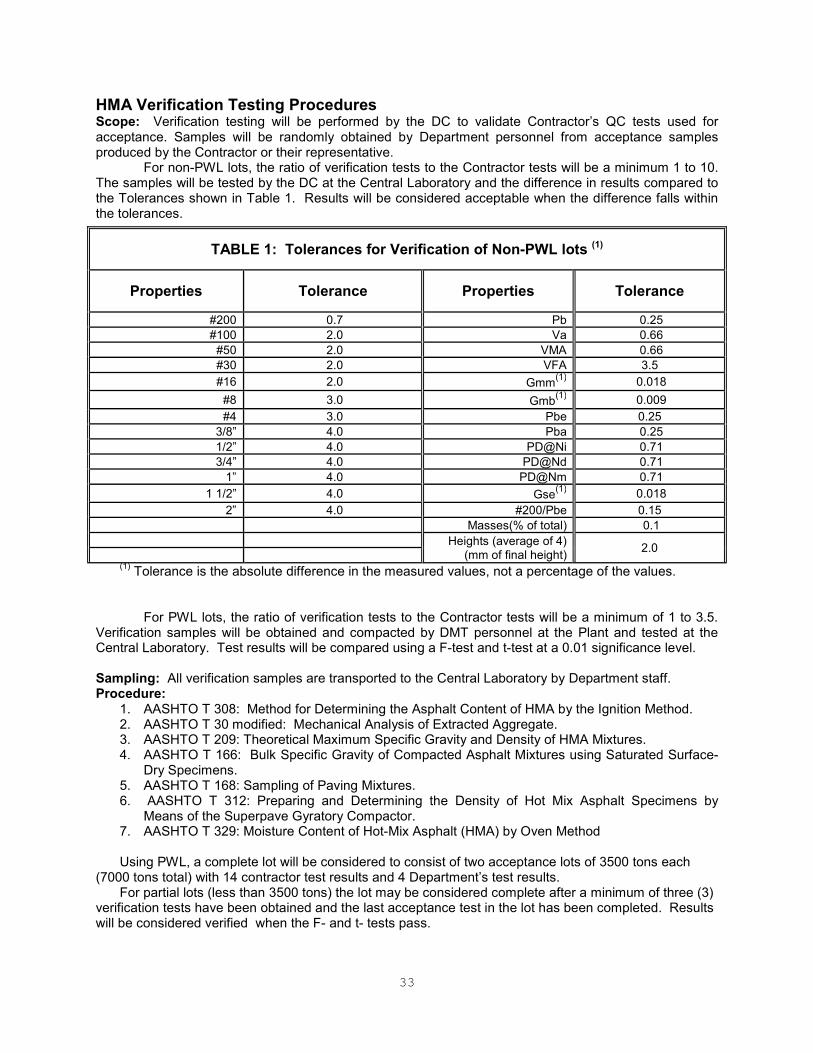
33
HMA Verification Testing Procedures Scope: Verification testing will be performed by the DC to validate Contractor’s QC tests used for acceptance. Samples will be randomly obtained by Department personnel from acceptance samples produced by the Contractor or their representative.
For non-PWL lots, the ratio of verification tests to the Contractor tests will be a minimum 1 to 10. The samples will be tested by the DC at the Central Laboratory and the difference in results compared to the Tolerances shown in Table 1. Results will be considered acceptable when the difference falls within the tolerances.
(1) Tolerance is the absolute difference in the measured values, not a percentage of the values.
For PWL lots, the ratio of verification tests to the Contractor tests will be a minimum of 1 to 3.5.
Verification samples will be obtained and compacted by DMT personnel at the Plant and tested at the Central Laboratory. Test results will be compared using a F-test and t-test at a 0.01 significance level. Sampling: All verification samples are transported to the Central Laboratory by Department staff. Procedure:
1. AASHTO T 308: Method for Determining the Asphalt Content of HMA by the Ignition Method. 2. AASHTO T 30 modified: Mechanical Analysis of Extracted Aggregate. 3. AASHTO T 209: Theoretical Maximum Specific Gravity and Density of HMA Mixtures. 4. AASHTO T 166: Bulk Specific Gravity of Compacted Asphalt Mixtures using Saturated Surface-
Dry Specimens. 5. AASHTO T 168: Sampling of Paving Mixtures. 6. AASHTO T 312: Preparing and Determining the Density of Hot Mix Asphalt Specimens by
Means of the Superpave Gyratory Compactor. 7. AASHTO T 329: Moisture Content of Hot-Mix Asphalt (HMA) by Oven Method
Using PWL, a complete lot will be considered to consist of two acceptance lots of 3500 tons each
(7000 tons total) with 14 contractor test results and 4 Department’s test results. For partial lots (less than 3500 tons) the lot may be considered complete after a minimum of three (3)
verification tests have been obtained and the last acceptance test in the lot has been completed. Results will be considered verified when the F- and t- tests pass.
TABLE 1: Tolerances for Verification of Non-PWL lots (1)
Properties Tolerance Properties Tolerance
#200 0.7 Pb 0.25
#100 2.0 Va 0.66
#50 2.0 VMA 0.66
#30 2.0 VFA 3.5
#16 2.0 Gmm(1)
0.018
#8 3.0 Gmb(1)
0.009
#4 3.0 Pbe 0.25
3/8” 4.0 Pba 0.25
1/2” 4.0 PD@Ni 0.71
3/4” 4.0 PD@Nd 0.71
1” 4.0 PD@Nm 0.71
1 1/2” 4.0 Gse(1)
0.018
2” 4.0 #200/Pbe 0.15
Masses(% of total) 0.1
Heights (average of 4) (mm of final height)
2.0

34
When any single sieve or volumetric result fails verification, HMA staff will notify IA staff. HMA staff shall review past tests specific to the type of material that failed to look for trends. The HMA staff shall contact the contractor’s Quality Control manager to notify them of the deficiency and request that the contractor investigate. Table 2 will be used to verify PPT samples and for HMA Independent Assurance. When testing a PPT sample, if any single sieve result or any of the individual volumetric results are rated a “D,” the PPT fails and the mix shall remain on PPT status. If the sample is rated a “C” or better, the mix will be placed on an “A” status.
(1) Tolerance is the absolute difference in the measured values, not a percentage of the values.
Report Form: MAT-408
TABLE 2: Independent Assurance and PPT Verification Tolerances (1)
Properties
Tolerance (maximum)
Tolerance (maximum)
Tolerance (maximum)
Tolerance
A (C x 0.25) B (C x 0.5) C D (>C)
#200 0.18 0.35 0.7 > 0.7
#100 0.5 1.0 2.0 > 2.0
#50 0.5 1.0 2.0 > 2.0
#30 0.5 1.0 2.0 > 2.0
#16 0.5 1.0 2.0 > 2.0
#8 0.5 1.0 3.0 > 3.0
#4 0.5 1.0 3.0 > 3.0
3/8” 1.0 2.0 4.0 > 4.0
1/2” 1.0 2.0 4.0 > 4.0
3/4” 1.0 2.0 4.0 > 4.0
1” 1.0 2.0 4.0 > 4.0
1 1/2” 1.0 2.0 4.0 > 4.0
2” 1.0 2.0 4.0 > 4.0
Pb 0.06 0.12 0.25 > 0.25
Va 0.18 0.35 0.71 > 0.71
VMA 0.18 0.35 0.71 > 0.71
VFA 3.5 3.5 3.5 > 3.5
Gmm 0.005 0.009 0.018 > 0.018
Gmb 0.003 0.006 0.011 > 0.011
Pbe 0.06 0.12 0.25 > 0.25
Pba 0.06 0.12 0.25 > 0.25
PD@Ni 0.18 0.35 0.71 > 0.71
PD@Nd 0.18 0.35 0.71 > 0.71
PD@Nm 0.18 0.35 0.71 > 0.71
Gse 0.005 0.009 0.018 > 0.018
#200/Pbe 0.03 0.07 0.15 > 0.15
Masses(% of total) 0.025% 0.05% 0.1% > 0.1%
Heights (average of 4) (mm of final height)
0.5
1.0
2.0
> 2.0

35
Mix Design / Job Mix Evaluation Scope: In order for a JMF to be approved, the properties of the aggregate components or mix shall meet the verification tolerances shown in Table 3. Sampling: As part of the JMF submittal, the Producer shall submit the following samples to the Division of Material Testing:
• 4 - one quart cans of PG binder, with corresponding Safety Data Sheet (SDS)
• 1 - 50 lbs bag of RAP
• 2 – 50 lbs bag of plant blended virgin aggregate
• 2 - 10,000 kg boxed split sample material for TSR design Procedure: Testing will be performed by the DMT to evaluate each proposed JMF and will include: Aggregate Components Consensus Properties Verification:
1. AASHTO T27: Mechanical Analysis of Aggregate 2. AASHTO T85: Coarse Aggregate Specific Gravity 3. AASHTO T84: Fine Aggregate Specific Gravity 4. ASTM D 5821: Coarse Aggregate Angularity 5. AASHTO T304, Method A: Fine Aggregate Angularity 6. ASTM D 4791: Flat and Elongated Particles (1:5) 7. AASHTO T176: Sand Equivalent
Mix Verification: 1.AASHTO T209: Theoretical Maximum Specific Gravity and Density of Bituminous Paving Mixtures. 2. AASHTO T166: Bulk Specific Gravity of Compacted Asphalt Mixtures using Saturated Surface-Dry Specimens. 3. AASHTO T312: Preparing and Determining the Density of Hot Mix Asphalt Specimens by Means of the Superpave Gyratory Compactor 4. AASHTO R35: Air Voids, VMA, VFA, Density to Nini 5. AASHTO T283: Resistance of Compacted Asphalt Mixtures to Moisture-Induced Damage
TABLE 3: JMF EVALUATION TOLERANCES (1)
Properties Tolerance b Properties Tolerance b
#200 1.0 Gmm 0.022
#100 3.0 Gmb 0.020
#50 3.0 Pba 0.6
#30 4.0 PD@Ni 1.5
#16 4.0 Gse 0.052
#8 5.0 Gsb 0.028
#4 5.0 Gsa 0.025
3/8” 5.0 CAA (1 face/2 faces) 10
½” 4.0 SE 15
¾” 4.0 FAA 0.8
1” 3.0 F & E 5.0
Va 1.3 TSR 15 & Minimal Stripping VMA 1.3
VFA 6.0 (1)
Tolerance is the absolute difference in the measured values, not a percentage of the values. Report Form: MAT-418
36
Resistance of Compacted HMA to Moisture Induced Damage Scope: Preparation of specimens and measurement of the change of diametral tensile strength resulting from the effects of saturation and accelerated water conditioning of compacted HMA mixtures in the laboratory. This test may be performed on HMA laboratory mixture, mixtures sampled from newly loaded trucks, field pavement samples, and pavement cores. Sampling and Procedure: AASHTO T 283 modified Report Form: AASHTO T 283 modified Table 1, Moisture Damage Laboratory Data Sheet or MAT-428
Volumetric and Specific Gravity Using Gyratory Compactor Scope: These methods cover the determination of volumetric and specific gravity calculations of test specimens made by Superpave gyratory compactor. Sampling: AASHTO T 168 modified, AASHTO R 47 Procedure: AASHTO M 323, and AASHTO R 35 Report Form: MAT-412s
Performance Graded Asphalt Binder (PGAB) Scope: PGAB suppliers are prequalified by the DMT in accordance with AASHTO R 26 modified. To maintain qualified status, suppliers must submit monthly split samples to the DMT. HMA producers must maintain a log of binder deliveries using a MAT-435 or equivalent approved ny the Engineer. Requirements: A Certified Test Report and bill of lading representing each delivery must be provided to the producer in accordance with AASHTO R 26 modified. Upon material delivery, plant personnel shall record lot number, date, grade of binder, witnessed by, hauler name, liquid supplier, ticket number, receiving storage tank number, quantity received, and previous tank status (quantity) in the binder log (MAT-435). The Contractor shall provide binder samples from the delivery upon request of DC. The blending of PG binder from different suppliers is not allowed unless the HMA producer submits a QC plan for this purpose. Sampling: In accordance with AASHTO T 40 Procedure: In accordance with all AASHTO standard methods of test listed in AASHTO 332
Report Form: QC Plan / MAT-401
DENSITY OF SOIL AND SOIL - AGGREGATES Scope: The Contractor shall determine of the in-place density of soil and soil aggregate by using a measurement device approved by the Engineer. Density measurements shall be performed where specified in the Contract. Procedure: Field testing shall be performed in accordance with AASHTO T 310 or other approved industry standard test method. The density results obtained shall be reported as a percent of the maximum dry density as determined by AASHTO T 180 Method D. Correlation: All gauges shall be correlated annualy prior to use on Department projects. Correlation blocks shall be provided by the Department or the gauge manufacturer. The gauge shall be correlated in accordance with manufacturer’s recommendations. Standardization: As a minimum, standardization of the gauge shall be performed daily prior to its use. This process shall be performed in accordance with the manufacturer’s recommendations. Report Form: Form CON-125
DENSITY OF IN-PLACE ASPHALT PAVEMENT BY THE CORE METHOD Procedure: Refer to Standard Operating Procedure (SOP) in Appendix G

37
Chapter 5 – AMRL Document
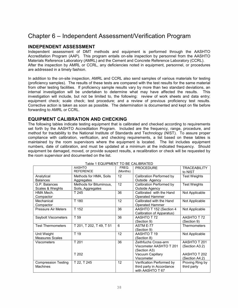
38
Chapter 6 – Independent Assessment/Verification Program
INDEPENDENT ASSESSMENT Independent assessment of DMT methods and equipment is performed through the AASHTO Accreditation Program (AAP). This program entails on-site inspection by personnel from the AASHTO Materials Reference Laboratory (AMRL) and the Cement and Concrete Reference Laboratory (CCRL). After the inspection by AMRL or CCRL, any deficiencies noted in equipment, personnel, or procedures are addressed in a timely fashion. In addition to the on-site inspection, AMRL and CCRL also send samples of various materials for testing (proficiency samples). The results of these tests are compared with the test results for the same material from other testing facilities. If proficiency sample results vary by more than two standard deviations, an internal investigation will be undertaken to determine what may have affected the results. This investigation will include, but not be limited to, the following: review of work sheets and data entry; equipment check; scale check; test procedure; and a review of previous proficiency test results. Corrective action is taken as soon as possible. The determination is documented and kept on file before forwarding to AMRL or CCRL.
EQUIPMENT CALIBRATION AND CHECKING The following tables indicate testing equipment that is calibrated and checked according to requirements set forth by the AASHTO Accreditation Program. Included are the frequency, range, procedure, and method for tractability to the National Institute of Standards and Technology (NIST). To assure proper compliance with calibration, verification, and checking requirements, a list based on these tables is maintained by the room supervisors where the equipment is located. The list includes equipment numbers, date of calibration, and must be updated at a minimum at the indicated frequency. Should equipment be damaged, moved, or provide suspect results, a recalibration or check will be requested by the room supervisor and documented on the list.
Table 1 EQUIPMENT TO BE CALIBRATED
AASHTO REFERENCE
FREQ. (Months)
PROCEDURE TRACEABILITY to NIST
Analytical Balances
Methods for HMA, Soils Aggregates
12 Calibration Performed by Outside Agency
Test Weights
G.P. Balances Scales & Weights
Methods for Bituminous, Soils, Aggregates
12 Calibration Performed by Outside Agency
Test Weights
HMA Mech. Compactor
T 245 36 Calibrated with the Hand Operated Hammer
Not Applicable
Mechanical Compactor
T 180 12 Calibrated with the Hand Operated Hammer
Not Applicable
Pressure Air Meters T 152 36 AASHTO T 152 (Section 4 Calibration of Apparatus)
Not Applicable
Saybolt Viscometers T 59 36 AASHTO T 72 (Section 9)
AASHTO T 72 (Section 9)
Test Thermometers T 201, T 202, T 49, T 51 6 ASTM E-77 (Section 9)
Thermometers
Unit Weight Measures Scales
T 19 12 AASHTO T 19 (Section 8)
Not Applicable
Viscometers T 201 T 202
36 Zeithfuchs Cross-arm Viscometer AASHTO T 201 (Section A3) Vacuum Capillary Viscometer
AASHTO T 201 (Section A3.2) AASHTO T 202 (Section A4.2)
Compression Testing Machines
T 22, T 245 12 Verification Performed by third party in Accordance with AASHTO T 67
Proving Ring by third party
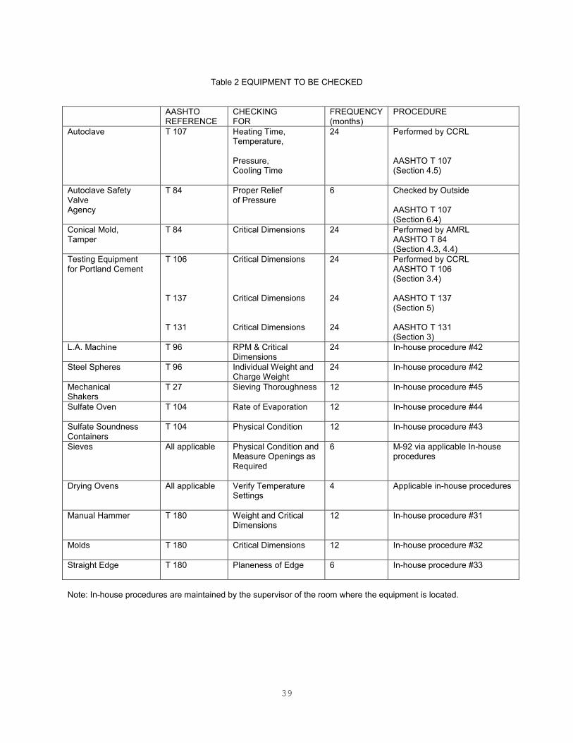
39
Table 2 EQUIPMENT TO BE CHECKED
AASHTO REFERENCE
CHECKING FOR
FREQUENCY (months)
PROCEDURE
Autoclave T 107 Heating Time, Temperature, Pressure, Cooling Time
24 Performed by CCRL AASHTO T 107 (Section 4.5)
Autoclave Safety Valve Agency
T 84 Proper Relief of Pressure
6 Checked by Outside AASHTO T 107 (Section 6.4)
Conical Mold, Tamper
T 84 Critical Dimensions 24 Performed by AMRL AASHTO T 84 (Section 4.3, 4.4)
Testing Equipment for Portland Cement
T 106 T 137 T 131
Critical Dimensions Critical Dimensions Critical Dimensions
24 24 24
Performed by CCRL AASHTO T 106 (Section 3.4) AASHTO T 137 (Section 5) AASHTO T 131 (Section 3)
L.A. Machine T 96 RPM & Critical Dimensions
24 In-house procedure #42
Steel Spheres T 96 Individual Weight and Charge Weight
24 In-house procedure #42
Mechanical Shakers
T 27 Sieving Thoroughness 12 In-house procedure #45
Sulfate Oven T 104 Rate of Evaporation 12 In-house procedure #44
Sulfate Soundness Containers
T 104 Physical Condition 12 In-house procedure #43
Sieves All applicable Physical Condition and Measure Openings as Required
6 M-92 via applicable In-house procedures
Drying Ovens All applicable Verify Temperature Settings
4 Applicable in-house procedures
Manual Hammer T 180 Weight and Critical Dimensions
12 In-house procedure #31
Molds T 180 Critical Dimensions 12 In-house procedure #32
Straight Edge T 180 Planeness of Edge 6 In-house procedure #33
Note: In-house procedures are maintained by the supervisor of the room where the equipment is located.
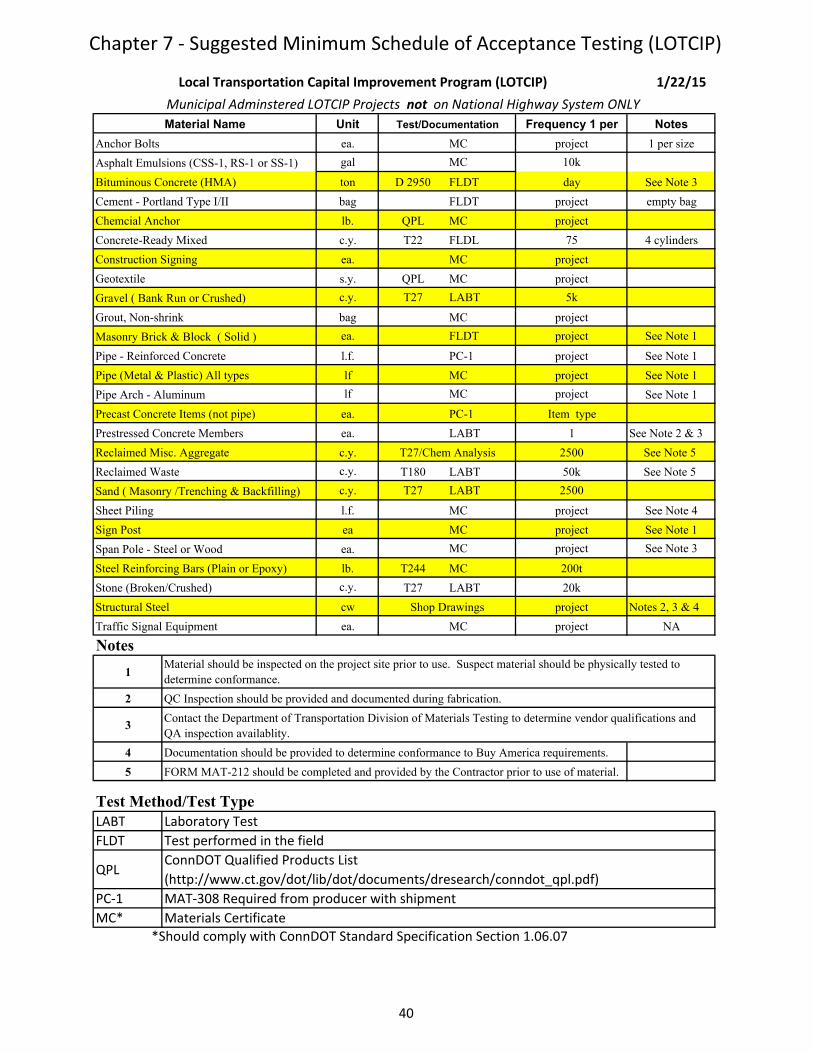
Chapter 7 - Suggested Minimum Schedule of Acceptance Testing (LOTCIP)
Unit Frequency 1 per Notes
Anchor Bolts ea. MC project 1 per size
Asphalt Emulsions (CSS-1, RS-1 or SS-1) gal MC 10k
Bituminous Concrete (HMA) ton D 2950 FLDT day See Note 3
Cement - Portland Type I/II bag FLDT project empty bag
Chemcial Anchor lb. QPL MC project
Concrete-Ready Mixed c.y. T22 FLDL 75 4 cylinders
Construction Signing ea. MC project
Geotextile s.y. QPL MC project
Gravel ( Bank Run or Crushed) c.y. T27 LABT 5k
Grout, Non-shrink bag MC project
Masonry Brick & Block ( Solid ) ea. FLDT project See Note 1
Pipe - Reinforced Concrete l.f. PC-1 project See Note 1
Pipe (Metal & Plastic) All types lf MC project See Note 1
Pipe Arch - Aluminum lf MC project See Note 1
Precast Concrete Items (not pipe) ea. PC-1 Item type
Prestressed Concrete Members ea. LABT 1 See Note 2 & 3
Reclaimed Misc. Aggregate c.y. 2500 See Note 5
Reclaimed Waste c.y. T180 LABT 50k See Note 5
Sand ( Masonry /Trenching & Backfilling) c.y. T27 LABT 2500
Sheet Piling l.f. MC project See Note 4
Sign Post ea MC project See Note 1
Span Pole - Steel or Wood ea. MC project See Note 3
Steel Reinforcing Bars (Plain or Epoxy) lb. T244 MC 200t
Stone (Broken/Crushed) c.y. T27 LABT 20k
Structural Steel cw project Notes 2, 3 & 4
Traffic Signal Equipment ea. MC project NA
Notes
1
2
3
4 Documentation should be provided to determine conformance to Buy America requirements.
5 FORM MAT-212 should be completed and provided by the Contractor prior to use of material.
LABT
FLDT
QPL
PC-1
MC*
Municipal Adminstered LOTCIP Projects not on National Highway System ONLY
*Should comply with ConnDOT Standard Specification Section 1.06.07
Material Name Test/Documentation
Local Transportation Capital Improvement Program (LOTCIP) 1/22/15
Materials Certificate
T27/Chem Analysis
Shop Drawings
Material should be inspected on the project site prior to use. Suspect material should be physically tested to
determine conformance.
Contact the Department of Transportation Division of Materials Testing to determine vendor qualifications and
QA inspection availablity.
QC Inspection should be provided and documented during fabrication.
Test Method/Test Type
Laboratory Test
Test performed in the field
ConnDOT Qualified Products List
(http://www.ct.gov/dot/lib/dot/documents/dresearch/conndot_qpl.pdf)
MAT-308 Required from producer with shipment
40

Chapter 8 - Minimum Schedule for Acceptance Testing Chapter 8_Acceptance Testing v12a8
Legend
Test Type: FLDT
LABT
FLABT
LMCT*
MC*
MCCTR*
PC1
QPL
Visual
Qualified Product List
*Materials Certificates and Certified Test Reports must comply with Standard Specification Section 1.06.07. Note: Materials Certificates for items composed of, or containing,
steel or cast iron must also indicate where the steel and cast iron was produced and fabricated.
Self Certification from producer supplied per shipment
Field and Laboratory Testing
1 per "quantity" indicates that all the quantity of each type (size/shape/composition) of material, per item, from a single vendor and manufacturer must be represented
on a single or multiple Request for Test(s) (MAT-100). MAT-100(s) total represented quantity must match total quantity installed.
Laboratory Test
Lab Test, Mat Cert and Cert Test Report (Originals Required)
Material Unit: Unit of Material that defines a quantity represented by a sample. Example: A sample of concrete represents 50 CY of material regardless of what the item unit is.
Responsibility: Person who performs the test.
Test Method: AASHTO or ASTM test method. See below.
Test performed in the field
Materials Certificate and Certified Test Report (Originals Required)
Materials Certificate (Original Required)
Item: Standard Specification Section and the first four digits of the Contract Item number.
Title: Generally the overall subject of the Standard Specification Section and the Contract Item numbers.
Item Unit: Generally the pay unit of the Contract Item.
Sample Size: Size of Sample.
Project Inspector must visually inspect upon delivery/installation. Visual
inspection by DMT staff denotes witnessing fabrication of material where it
is being fabricated. Documentation of visual inspection on the project by
project staff is in accordance with District/Office of Construction policies.
Test Type: Describes the test, where the test is performed, or what is required to be submitted with the MAT-100.
Material #: Code used in SiteManager and by the Division of Materials Testing to identify component materials used in Contract Items.
Material Name: Definition of the Material #.
Sample Type: Acceptance (Prod) or Information requires a MAT-100 to be submitted. Accept (Field) does not require a MAT-100 to be submitted.
Frequency: Number of tests required per quantity of material using the material units: (E) English (M) Metric.
41

Chapter 8 - Minimum Schedule for Acceptance Testing Chapter 8_Acceptance Testing v12a8
X=Not Standard,
A=Spec ProMaterial Material Material Sample Test Test Test
Item Title Unit # Name Unit Type Method Type Responsibility (E) (M) lbs kg
00.00 A Bit. Surface ton 04015 Bit. Conc. Surface Course FAA ton
01.01 Environmental 00307 Absorbing Compound lb. No Req for Test NA Visual Project Staff
Items 03166 Sheeting, Polyethylene s.y. No Req for Test NA Visual Project Staff
04XXX Bit. Concrete (Various) ton No Req for Test NA Visual Project Staff
04776 Hay, Baled ea. No Req for Test NA Visual Project Staff
04901 Bedding Material c.y. No Req for Test NA Visual Project Staff
08044 Retaining Wall - Precast Conc. ea. Accept (Prod) NA PC1 Central Lab 1 1
02.01 Clearing &
Grubbing l.s. 00000 No Request for Test Required.
02.02 Rdwy Ex,
Formation of 08037X Reclaimed Waste ( OFFSITE ) Accept (Prod) MCCTR District Lab 2.5k 1.9k 160 72
Embankment
and Disposal 08037 Reclaimed Waste Information T180 LABT District Lab 20k 15k 160 72
of Surplus
Material 08039 Embankment Material Accept(Field) D 6938 FLDT Project Staff 2.5k 1.9k
02.03 Structure c.y.
Excavation
02.04 Cofferdam l.f. 00000 No Request for Test Required.
02.05 Trench Excav c.y. 00000 No Request for Test Required.
02.06 Ditch Excav c.y. 00000 No Request for Test Required.
02.07 Borrow c.y. 08031 To Be Determined. c.y. Information T180 LABT District Lab 20k 15k 160 72
Accept(Field) D 6938 FLDT Project Staff 2.5k 1.9k
02.08 Free-Draining c.y. 08037X Reclaimed Waste (OFFSITE) Accept (Prod) Chem (Offsite ONLY) MCCTR District Lab 2.5k 1.9k 160 72
Material 08037 Reclaimed Waste Accept (Prod) T27 LABT District Lab 5k 3.8k 160 72
08039 Embankment Material Information T180 LABT District Lab 20k 15k 160 72
Accept(Field) D 6938 FLDT Project Staff 2.5k 1.9k
02.09 Subgrade, Form s.y. 00000
02.10 Water Pollution
Control est. 03496 Sheeting, Reinforced Plastic l.f. No Req for Test NA Visual Project Staff
04XXX Bit. Concrete (Various) ton No Req for Test NA Visual Project Staff
03985 Geotextile s.y. No Req for Test NA QPL/MC Project Staff
02.12 Subbase c.y. 04819 Gravel (Bank Run)
08034 Stone (Broken/Crushed) Accept (Prod) T27 LABT District Lab 5k 3.8k 160 72
08035 Gravel (Crushed) Information T180 LABT District Lab 20k 15k 160 72
08036 Recl. Misc. Agg. Accept(Field) D 6938 FLDT Project Staff 2.5k 1.9k
08036X Recl. Misc. Agg. (OFFSITE) Accept (Prod) Chem (Offsite ONLY) MCCTR District Lab 2.5k 1.9k 160 72
02.13 Granular Fill c.y.
02.14 Comp Gran Fill
c.y.
NA
NA
See 06.01 for Portland Cement Concrete materials, 06.51 for pipe, 07.03 for Riprap, and 09.53 for Sod.
NA
NA
Frequency
1 per
See Note 13.
NA
Sample Size
NA
NA
All Materials and Frequencies as listed under 02.12, except Lab (T180) and Field Density (D6938) are not required for this item.
c.y.
00000
Chem(offsite ONLY)
c.y.
NA
See Note 13
See Note 13.
c.y.
NA
See Special Provision
No Request for Test Required.
c.y.
All Materials and Frequencies as listed under 02.12.
See Note 13.
No Request for Test Required.
42
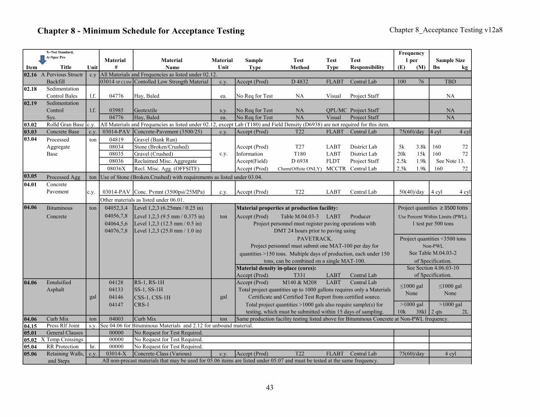
Chapter 8 - Minimum Schedule for Acceptance Testing Chapter 8_Acceptance Testing v12a8
X=Not Standard,
A=Spec ProMaterial Material Material Sample Test Test Test
Item Title Unit # Name Unit Type Method Type Responsibility (E) (M) lbs kg
Frequency
1 per Sample Size
02.16 A Pervious Structr c.y
Backfill 03014 SP CLSM Contolled Low Strength Material c.y. Accept (Prod) D 4832 FLABT Central Lab 100 76 TBD
02.18 Sedimentation
Control Bales l.f. 04776 Hay, Baled ea. No Req for Test NA Visual Project Staff
02.19 Sedimentation
Control l.f. 03985 Geotextile s.y. No Req for Test NA QPL/MC Project Staff
Sys. 04776 Hay, Baled ea. No Req for Test NA Visual Project Staff
03.02 Rolld Gran Base c.y.
03.03 Concrete Base c.y. 03014-PAV Concrete-Pavement (3500/25) c.y. Accept (Prod) T22 FLABT Central Lab 4 cyl 4 cyl
03.04 Processed ton 04819 Gravel (Bank Run)
Aggregate 08034 Stone (Broken/Crushed) Accept (Prod) T27 LABT District Lab 5k 3.8k 160 72
Base 08035 Gravel (Crushed) Information T180 LABT District Lab 20k 15k 160 72
08036 Reclaimed Misc. Aggregate Accept(Field) D 6938 FLDT Project Staff 2.5k 1.9k
08036X Recl. Misc. Agg. (OFFSITE) Accept (Prod) Chem(Offsite ONLY) MCCTR Central Lab 2.5k 1.9k 160 72
03.05 Processed Agg ton
c.y. 03014-PAV Conc. Pvmnt (3500psi/25MPa) c.y. Accept (Prod) T22 LABT Central Lab 4 cyl 4 cyl
04.06 Bituminous ton 04052,3,4 Level 1,2,3 (6.25mm / 0.25 in)
Concrete 04056,7,8 Level 1,2,3 (9.5 mm / 0.375 in) ton Accept (Prod) Table M.04.03-3 LABT Producer
04064,5,6 Level 1,2,3 (12.5 mm / 0.5 in)
04076,7,8 Level 1,2,3 (25.0 mm / 1.0 in)
Accept (Prod) T331 LABT Central Lab
04.06 Emulsified 04128 RS-1, RS-1H Accept (Prod) M140 & M208 LABT Central Lab
Asphalt 04133 SS-1, SS-1H
04146 CSS-1, CSS-1H
04147 CRS-1
10k 38kl 2 qts 2L
04.06 Curb Mix ton 04003 Curb Mix ton
04.15 Press Rlf Joint s.y.
05.01 General Clauses 00000 No Request for Test Required.
05.02 X Temp Crossings 00000 No Request for Test Required.
05.04 RR Protection hr. 00000 No Request for Test Required.
05.06 Retaining Walls, c.y. 03014-X Concrete-Class (Various) c.y. Accept (Prod) T22 FLABT Central Lab
and Steps
gal gal
≤1000 gal
None
≤1000 gal
NoneTotal project quantities up to 1000 gallons requires only a Materials
Certificate and Certified Test Report from certified source.
Total project quantities >1000 gals also require sample(s) for >1000 gal
Use of Stone (Broken.Crushed) with requirements as listed under 03.04.
All Materials and Frequencies as listed under 02.12.
4 cyl
Material properties at production facility: Project quantities ≥ 3500 tons
See Note 13.
Use Percent Within Limits (PWL).
NA
quantities >150 tons. Multiple days of production, each under 150
tons, can be combined on a single MAT-100.
NA
c.y.
NA
PAVETRACK. Project quantities <3500 tons
Project personnel must submit one MAT-100 per day for Non-PWL
Material density in-place (cores): See Section 4.06.03-10
of Specification.
Same production facility testing listed above for Bituminous Concrete at Non-PWL frequency.
75(60)/day
All non-precast materials that may be used for 05.06 items are listed under 05.07 and must be tested at the same frequency.
All Materials and Frequencies as listed under 02.12, except Lab (T180) and Field Density (D6938) are not required for this item.
75(60)/day
50(40)/day
Project personnel must register paving operations with 1 test per 500 tons
DMT 24 hours prior to paving using
See Table M.04.03-2
of Specification.
See 04.06 for Bituminous Materials and 2.12 for unbound material.
>1000 gal
testing, which must be submitted within 15 days of sampling.
04.01
Other materials as listed under 06.01.
Concrete
Pavement
43

Chapter 8 - Minimum Schedule for Acceptance Testing Chapter 8_Acceptance Testing v12a8
X=Not Standard,
A=Spec ProMaterial Material Material Sample Test Test Test
Item Title Unit # Name Unit Type Method Type Responsibility (E) (M) lbs kg
Frequency
1 per Sample Size
05.07 Catch Basins, ea. 00327 Water gal No Req for Test NA Visual Project Staff
Manholes & 01422 Precast Concrete Section
Drop Inlets 01440A Catch Basin - Precast ( Complete )
01441A Manhole - Precast ( Complete )
03025 Mortar (prebagged)
03066 Cement - Portland Type I/II No Req for Test NA
06552 Lime - Hydrated
03200 Masonry Brick & Block ( Solid )
03201 Brick (Clay)
03209 Manhole Cover and/or Frame
03212 Catch Basin Frame and/or Grate
04697 Sand ( Masonry ) - Grading A
04704 Sand ( Masonry ) - Grading B
04819 Gravel ( Bank Run )
08034 Stone ( Broken / Crushed )
08035 Gravel ( Crushed ) Accept (Prod) T27 LABT District Lab 5k 3.8k 160 72
08036 Reclaimed Misc. Aggregate
08036X Recl. Misc. Agg. (OFFSITE) Accept (Prod) MCCTR District Lab 2.5k 1.9k 160 72
05.08 Shear Connectors l.s. 03542 Stud Shear Connector ea. Accept (Prod) AWS D1.5 MCCTR Central Lab
05.09 Welded Studs ea. 03543 Studs - Welding ea. Accept (Prod) AWS D1.5 MCCTR Central Lab
05.13 PVC Pipe l.f. 02649 Pipe - Polyvinyl Chloride l.f. No Req for Test NA Visual Project Staff
05.14 Pstrsd Concrete l.f. 03040 Grout, Non-shrink bag No Req for Test NA Visual Project Staff
Members 03050 Concrete Members, Prestressed l.f. Accept (Prod) NA Visual Lab & Project
05.20 X Asphalt Plug c.f.
Joint
05.21 Elastomeric c.i. 03040 Grout, Non-shrink
Bearing Pads 03505-L Bearing Pads (Laminated) ea.
03505-P Bearing Pads (Plain) ea.
03506 Bonding Adhesive - Bearing Pads tbd Accept (Prod) NA MCCTR Central Lab
05.22 Elastomeric l.f. 03432 Elastomeric Compression Seal l.f. No Req for Test NA MC Project Staff
Comp. Seal 03040 Grout, Non-shrink
06.01 c.y. 00804 Box Culvert (Precast)
01422 Precast Concrete Section
03014-X Concrete-Class X (A, C or F)
03014-SP_K Concrete Special Provision Accept (Prod) T22 FLABT Central Lab
03014-HE Concrete, High Early
03040 Grout, Non-shrink bag No Req for Test NA Visual Project Staff
03016 Grout (Batched) c.y. Accept (Prod) T106 FLABT Central Lab
03094 Joint Sealer gal
(Cont) 03158 Preformed Expansion Joint Filler ea. No Req for Test NA MC Project Staff NA
08010 Exp. Jnt Asphalt Plug c.f No Req for Test NA Project StaffMC
Concrete for
StructuresSee Note 2.ea.
See Note 9.
25 122.5k 1.9k
1 per size
See Note 3.
See Note 5.
4 cyl
MCCTRNA
quantity
NA
See Note 3.
NA
See Note 9.
quantity
See Note 2.
Central Lab
See Note 4.
See requirements for material #03040 under item 05.14.
1 per size
See Note 12.
quantity
c.y.
NA
Accept (Prod)
c.y.
See requirements for material #03040 under item 05.14.
Chem (Offsite ONLY)
Accept (Prod)
NAAccept (Prod)
Central Lab
1
1
See Note 9.
See Note 1.
MC
ea.
1
Project Staff
1 NA
NA
Central Lab
LABT District Lab
Visual
PC1
NA
75(60)/day
Accept (Prod)
ea. Central Lab
NAAccept (Prod)
bag
c.y.
ea. Accept (Prod) LABT
T27
Lab & ProjectVisual
44
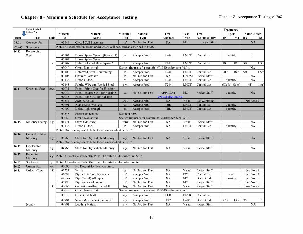
Chapter 8 - Minimum Schedule for Acceptance Testing Chapter 8_Acceptance Testing v12a8
X=Not Standard,
A=Spec ProMaterial Material Material Sample Test Test Test
Item Title Unit # Name Unit Type Method Type Responsibility (E) (M) lbs kg
Frequency
1 per Sample Size
06.01 Concrete for 03444 Closed Cell Elastomer l.f. No Req for Test NA MC Project Staff NA
(Cont) Structures
06.02 Reinforcing
Steel 02995 Dowel Splice System (Epxy Ctd)
02997 Dowel Splice System
lb. 02998 Deformed Steel Bars, Epxy Ctd lb. Accept (Prod) T244 LMCT Central Lab 200t 180t 5ft 1.5m
03040 Grout, Non-shrink
03100 Deformed Steel, Reinforcing lb. Accept (Prod) T244 LMCT Central Lab 200t 180t 5ft 1.5m
03105 Chemical Anchor lb. No Req for Test NA QPL/MC Project Staff
03138 Dowels, Steel ea. Accept (Prod) T244 LMCT Central Lab
03145 Fabric, Wire and Welded Steel s.y. Accept (Prod) T244 LMCT Central Lab 6k m2
1 m2
06.03 Structural Steel cwt. 00031 Paint - Prime Coat for Existing
00032 Paint - Interm. Coat for Existing No Req for Test NEPCOAT
00033 Paint - Top Coat for Existing www.nepcoat.org03537 Steel, Structual cwt. Accept (Prod) NA Visual Lab & Project
03691 Nuts and/or Washers ea. Accept (Prod) TBD LMCT Central Lab
03707 Bolts, High strength ea. Accept (Prod) TBD LMCT Central Lab
03543 Shear Connectors
03040 Grout, Non-shrink
06.05 Masonry Facing s.y. 04771 Stone (Masonry) tons No Req for Test NA Visual Project Staff
03138 Dowels, Steel lb. Accept (Prod) NA LMCT Central Lab
06.06 Cement Rubble
Masonry c.y. 04765 Stone for Dry Rubble Masonry c.y. No Req for Test NA Visual Project Staff
Note: Mortar components to be tested as described in 05.07.
06.07 Dry Rubble
Masonryc.y. 04765 Stone for Dry Rubble Masonry c.y. No Req for Test NA Visual Project Staff
06.09 Repointed
Masonrys.y.
06.11 Shotcrete c.y. Note: All materials under 06.11 will be tested as described in 06.01.
06.12 Curing Box ea. 00000 No Request for Test Required.
06.51 Culverts/Pipe l.f. 00327 Water gal No Req for Test NA Visual Project Staff
00699 Pipe - Reinforced Concrete l.f. Accept (Prod) NA PC1 Central Lab
various Pipe (Metal) All types l.f. Accept (Prod) NA MC District Lab
01790 Pipe Arch - Aluminum l.f. No Req for Test NA MC Project Staff
l.f. 03066 Cement - Portland Type I/II bag No Req for Test NA Visual Project Staff
03040 Grout, Non-shrink
03016 Grout (Batched) c.y. Accept (Prod) T106 FLABT Central Lab
04704 Sand (Masonry) - Grading B c.y. Accept (Prod) T27 LABT District Lab 2.5k 1.9k 25 12
(cont.) 04901 Bedding Material c.y. No Req for Test NA Visual Project Staff NA
NA
NA
quantity
MC quantitygal
See requirements for material #03040 under item 06.01.
quantity
Central Lab
Project Staff
See requirements for material #03040 under item 06.01.
60k ft2
1
NA
NA
1yd2
See Note 8.
quantity
quantity
size
See Note 2.
NA
See Note 7.
See Note 4.
NA
See Note 8.
See Note 9.
NA
NA
LMCT
Note: All steel reinforcement under 06.01 will be tested as described in 06.02.
ea. Accept (Prod) T244 quantity
See item 5.08.
Note: All materials under 06.09 will be tested as described in 05.07.
quantity
Note: Mortar components to be tested as described in 05.07.
See requirements for material #03040 under item 06.01
45
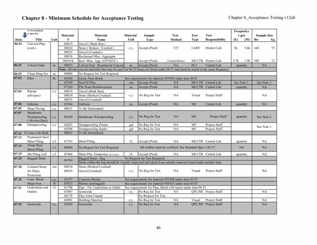
Chapter 8 - Minimum Schedule for Acceptance Testing Chapter 8_Acceptance Testing v12a8
X=Not Standard,
A=Spec ProMaterial Material Material Sample Test Test Test
Item Title Unit # Name Unit Type Method Type Responsibility (E) (M) lbs kg
Frequency
1 per Sample Size
06.51 Culverts/Pipe 04819 Gravel ( Bank Run )
(cont.) 08034 Stone ( Broken / Crushed ) c.y. Accept (Prod) T27 LABT District Lab 5k 3.8k 160 72
08035 Gravel (Crushed )
08036 Reclaimed Misc. Aggregate
08036X Recl. Misc. Agg. (OFFSITE ) Accept (Prod) Chem(Offsite) MCCTR District Lab 2.5k 1.9k 160 72
06.52 Culvert Ends ea. 00823 Culvert End - Reinforced Concrete ea. Accept (Prod) NA PC1 Central Lab
Note: All non-precast materials that may be used for 06.52 items are listed under 06.51 and must be tested at the same frequency.
06.53 Clean Drng Sys ea. 00000 No Request for Test Required.
07.02 Piles lb. 03040 Grout, Non-shrink
03549 Steel H Piles ton Accept (Prod) NA MCCTR Central Lab
07369 Pile Point Reinforcement ea. Accept (Prod) NA MCCTR Central Lab
07.03 Riprap c.y. 04819 Gravel (Bank Run)
(all types) 08034 Stone (Broken/Crushed)
08035 Gravel (Crushed)
07.04 Gabions c.y. 03546 Gabions ea. Accept (Prod) NA MC Central Lab
07.05 Slope Paving s.y. 08031 To Be Determined.
07.07 Membrane
Waterproofing s.y. 04199 Membrane Waterproofing s.y.( Woven Glass)
07.08 Dampproofing s.y. 04207 Dampproofing Primer gal No Req for Test NA MC Project Staff
04208 Dampproofing Sealer gal No Req for Test NA MC Project Staff
07.11 X Conc Crib Wall 08031 To Be Determined.
07.13 Permanent Steel
Sheet Piling s.f. 07762 Sheet Piling l.f. Accept (Prod) NA MCCTR Central Lab
07.14 Temp Steel
Sheet Pilings.f. 00000 No Request for Test Required.
07.15 Sht Piling Left s.f. 07466 Sheet Pile, Temporary left in place l.f. Accept (Prod) NA MCCTR Central Lab
07.25 Bagged Stone Bagged Stone - Bag No Request for Test Required.
07.28 Crushed Stone ton 08034 Stone (Broken/Crushed)
for Slope
Protection
08035 Gravel (Crushed)
Conc. Block s.y. 03197 Concrete Blocks
Slope Prot. lb 03025 Mortar (prebagged)
07.51 Underdrain and l.f. 01708 Pipe - For Underdrain or Outlet
Outlets 03985 Geotextile s.y. No Req for Test NA QPL/MC Project Staff
04178 Pipe Joint Cmpnd No Request for Test
04901 Bedding Material c.y. No Req for Test NA Visual Project Staff
07.55 Geotextile s.y. 03985 Geotextile s.y. No Req for Test NA QPL/MC Project Staff
c.y.
See Note 1.
NA
NA
quantity
NA
quantity NA
NA
NA
See Note 1.
quantity
quantity
See Note 1.
See Note 1.
NA
quantity
quantity
See requirements for material #03200 under item 05.07.
See requirements for Pipe, Metal (All types) under item 06.51.
All welders must be certified. See Standard Spec 1.05.17.
NANo Req for Test Project StaffMC
Stone within the bag should be visually inspected and taken from suitable material tested under another item.
See requirements for material #03025 under item 05.07.
See requirements for material #03040 under item 06.01
NA
NA
NA
NA
07.32
c.y. Project StaffVisualNANo Req for Test
04769
No Req for Test NA Visual Project Staff
NA
46
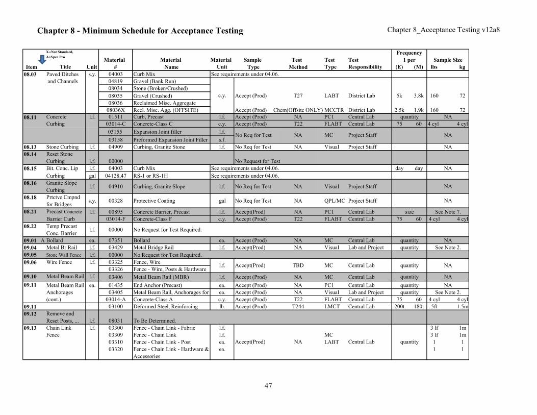
Chapter 8 - Minimum Schedule for Acceptance Testing Chapter 8_Acceptance Testing v12a8
X=Not Standard,
A=Spec ProMaterial Material Material Sample Test Test Test
Item Title Unit # Name Unit Type Method Type Responsibility (E) (M) lbs kg
Frequency
1 per Sample Size
08.03 Paved Ditches s.y. 04003 Curb Mix See requirements under 04.06.
and Channels 04819 Gravel (Bank Run)
08034 Stone (Broken/Crushed)
08035 Gravel (Crushed) Accept (Prod) T27 LABT District Lab 5k 3.8k 160 72
08036 Reclaimed Misc. Aggregate
08036X Recl. Misc. Agg. (OFFSITE) Accept (Prod) Chem(Offsite ONLY) MCCTR District Lab 2.5k 1.9k 160 72
08.11 Concrete l.f. 01511 Curb, Precast l.f. Accept (Prod) NA PC1 Central Lab
Curbing 03014-C Concrete-Class C c.y. Accept (Prod) T22 FLABT Central Lab 75 60 4 cyl 4 cyl
03155 Expansion Joint filler l.f.
03158 Preformed Expansion Joint Filler s.f.
08.13 Stone Curbing l.f. 04909 Curbing, Granite Stone l.f. No Req for Test NA Visual Project Staff
08.14 Reset Stone
Curbing l.f. 00000
Bit. Conc. Lip l.f. 04003 Curb Mix See requirements under 04.06. day day
Curbing gal 04128,47 RS-1 or RS-1H
08.16 Granite Slope
Curbingl.f. 04910 Curbing, Granite Slope l.f. No Req for Test NA Visual Project Staff
08.18 Prtctve Cmpnd
for Bridgess.y. 00328 Protective Coating gal No Req for Test NA QPL/MC Project Staff
08.21 Precast Concrete l.f. 00895 Concrete Barrier, Precast l.f. Accept(Prod) NA PC1 Central Lab
Barrier Curb 03014-F Concrete-Class F c.y. Accept (Prod) T22 FLABT Central Lab 75 60 4 cyl 4 cyl
08.22 Temp Precast
Conc. Barrierl.f. 00000 No Request for Test Required.
09.01 A Bollard ea. 07351 Bollard ea. Accept (Prod) NA MC Central Lab
09.04 Metal Br Rail l.f. 03429 Metal Bridge Rail l.f. Accept(Prod) NA Visual Lab and Project
09.05 Stone Wall Fence l.f. 00000 No Request for Test Required.
09.06 Wire Fence l.f. 03325 Fence, Wire
03326 Fence - Wire, Posts & Hardware
09.10 Metal Beam Rail l.f. 03406 Metal Beam Rail (MBR) l.f. Accept (Prod) NA MC Central Lab
09.11 Metal Beam Rail ea. 01435 End Anchor (Precast) ea. Accept (Prod) NA PC1 Central Lab
Anchorages 03405 Metal Beam Rail, Anchorages for ea. Accept (Prod) NA Visual Lab and Project
(cont.) 03014-A Concrete-Class A c.y. Accept (Prod) T22 FLABT Central Lab 75 60 4 cyl 4 cyl
09.11 03100 Deformed Steel, Reinforcing lb. Accept (Prod) T244 LMCT Central Lab 200t 180t 5ft 1.5m
09.12 Remove and
Reset Posts, ... l.f. 08031 To Be Determined.
09.13 Chain Link l.f. 03300 Fence - Chain Link - Fabric l.f. 3 lf 1m
Fence 03309 Fence - Chain Link l.f. 3 lf 1m
03310 Fence - Chain Link - Post ea. 1 1
03320 Fence - Chain Link - Hardware &
Accessories
ea. 1 1
size
quantity
NA
See Note 2.
Accept(Prod) TBD
quantity
See Note 7.
quantity
Project Staff
quantity
Accept(Prod)
MC
No Req for Test
See requirements under 04.06.
c.y.
NA MC
Central Lab quantity
NA
Central Lab
NA
NA
See Note 2.
NA
NA
08.15
LABT
MC
l.f.
NA
NA
NA
No Request for Test
NA
quantity
NA
quantity
quantity
47
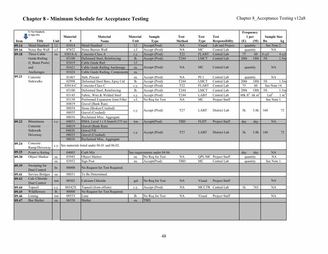
Chapter 8 - Minimum Schedule for Acceptance Testing Chapter 8_Acceptance Testing v12a8
X=Not Standard,
A=Spec ProMaterial Material Material Sample Test Test Test
Item Title Unit # Name Unit Type Method Type Responsibility (E) (M) lbs kg
Frequency
1 per Sample Size
09.14 Metal Handrail l.f. 03414 Metal Handrail l.f. Accept(Prod) NA Visual Lab and Project
09.16 Noise Bar Wall s.f. 07822 Noise Barrier Wall s.f. Accept (Prod) NA MC Central Lab
09.18 Three-Cable ea. 03014-A Concrete-Class A c.y. Accept (Prod) T22 FLABT Central Lab 75 60 4 cyl 4 cyl
Guide Railing 03100 Deformed Steel, Reinforcing lb. Accept (Prod) T244 LMCT Central Lab 200t 180t 5ft 1.5m
(I_Beam Posts) 03419 Cable Guide Rail l.f.
and 03421 Cable Guide Railing Anchorage ea.
Anchorages 03424 Cable Guide Railing, Components ea.
09.21 Concrete 01467 Slab, Precast ea. Accept (Prod) NA PC1 Central Lab
Sidewalks 02998 Deformed Steel Bars, Epxy Ctd lb. Accept (Prod) T244 LMCT Central Lab 200t 180t 5ft 1.5m
03014-C Concrete-Class C c.y. Accept (Prod) T22 FLABT Central Lab 75 60
03100 Deformed Steel, Reinforcing lb. Accept (Prod) T244 LMCT Central Lab 200t 180t 5ft 1.5m
03145 Fabric, Wire & Welded Steel s.y. Accept (Prod) T244 LABT Central Lab 6k m2
1 m2
03158 Preformed Expansion Joint Filler s.f. No Req for Test NA MC Project Staff
04819 Gravel (Bank Run)
08034 Stone (Broken/Crushed)
08035 Gravel (Crushed)
08036 Reclaimed Misc. Aggregate
09.22 Bituminous s.y. 04053 HMA, Level 1 ( 9.5mm/0.375 in) ton Accept(Prod) TBD FLDT Project Staff day day
Concrete 04819 Gravel (Bank Run)
Sidewalk 04820 Gravel Fill
Driveway 08035 Gravel (Crushed)
08036 Reclaimed Misc. Aggregate
09.24 Concrete
Ramp/Drivewayc.y.
09.25 Pvmnt for Railing 04003 Curb Mix day day
09.30 Object Marker ea. 03943 Object Marker ea. No Req for Test NA QPL/MC Project Staff NA
ea. 03952 Sign Post ea. Accept(Prod) TBD MC Central Lab
09.39 Sweeping for
Dust Controlhr. 00000 No Request for Test Required.
09.41 Service Bridges ea. 08031 To Be Determined.
09.42 Calc Chloride
Dust Controlton 00302 Calcium Chloride gal No Req for Test NA Visual Project Staff
09.44 Topsoil s.y. 00542X Topsoil (from offsite) c.y. Accept (Prod) NA MCCTR Central Lab 1k 765
09.45 Wildflowers lb. 00000 No Request for Test Required.
09.46 Liming ton 00533 Lime lb. No Req for Test NA Visual Project Staff
09.47 Bus Shelter ea. 06538 Shelter ea. TBD
NA
See materials listed under 06.01 and 06.02.
3.8k
NA
T27 160
NA
Accept (Prod) 72T27 LABT
5k
NA
NA
5k
Central Lab
District Lab
See requirements under 04.06.
LABT
Accept (Prod) MC
quantity
c.y.
See Note 2.
See Note 14.
NA
quantity
quantity
60k ft2
See Note 1.
NA
See Note 1.
quantity
quantity
72
1yd2
Accept (Prod)
NA
160
quantity
3.8k
NA
District Labc.y.
48

Chapter 8 - Minimum Schedule for Acceptance Testing Chapter 8_Acceptance Testing v12a8
X=Not Standard,
A=Spec ProMaterial Material Material Sample Test Test Test
Item Title Unit # Name Unit Type Method Type Responsibility (E) (M) lbs kg
Frequency
1 per Sample Size
09.49 Planting and ea. 00327P Water (plantings)
Mulching 00510 Peat c.y. No Req for Test NA Visual Project Staff
Trees, Shrubs 00533 Lime ton No Req for Test NA Visual Project Staff
Vines 00496 Fertilizer lb. No Req for Test NA MC Project Staff
and 00536 Plant Materials
Groundcover 00542P Topsoil - plantings (no turf estab) c.y. Accept (Prod) NA MCCTR Central Lab 1k 765
Plants 07547 Tree
09.50 Turf s.y. 00327P Water (plantings) gal No Req for Test NA Visual Project Staff
Establishment 00512 Fertilizer lb. No Req for Test NA MC Project Staff
Erosion Control 00497 Seed lb. No Req for Test NA MC Project Staff
00514 Hay Mulch s.y. No Req for Test NA Visual Project Staff
00533 Lime lb. No Req for Test NA Visual Project Staff
00534 Mulch - Wood Fiber lb. No Req for Test NA Visual Project Staff
00542 Topsoil (from project) c.y. No Req for Test NA Visual Project Staff
00542X Topsoil (from offsite) c.y. Accept (Prod) NA MCCTR Central Lab 1k 765
03982 Geotextiles, Erosion Control s.y. No Req for Test NA QPL Project Staff
09.53 Sodding s.y. 00518 Sod s.y. No Req for Test NA MC Project Staff
Other materials as listed in 09.50.
09.76 Barricade
Warning Lightsday 03603 Warning Lights ea. No Req for Test NA Visual Project Staff
09.77 Traffic Cone ea. 03934 Reflective Sheeting s.f. No Req for Test NA QPL/MC Project Staff
03948 Traffic Cones ea. No Req for Test NA Visual Project Staff
09.78 Traffic Drum ea. 03934 Reflective Sheeting s.f. No Req for Test NA QPL/MC Project Staff
03927 Traffic Drums ea. No Req for Test NA Visual Project Staff
09.79 Construction ea. 03934 Reflective Sheeting s.f. No Req for Test NA QPL/MC Project Staff
Barricades 03974 Construction Barricade ea. No Req for Test NA MC Project Staff
09.81 ea. 03934 Reflective Sheeting s.f. No Req for Test NA QPL/MC Project Staff
03948 Traffic Cones ea. No Req for Test NA Visual Project Staff
04709 Sand (trenching and backfilling) c.y. No Req for Test NA Visual Project Staff
10.02 Light Standards 01432 Foundation ( Precast ) ea. Accept (Prod) NA PC1 Central Lab
and Traffic 03014-A Concrete Class A c.y. Accept (Prod) T22 FLABT Central Lab 75 60 4 cyl 4 cyl
Control 03100 Deformed Steel ( Reinforcing ) lb. Accept (Prod) T244 LMCT Central Lab 200t 180t 5ft 1.5m
Foundations 03504 Anchor Bolts ea. Accept (Prod) TBD LMCT Central Lab
03711 Ground Rod ea. No Req for Test NA Visual Project Staff
10.03 Light Standards ea. 03704 Light Standard ea. Accept (Prod) TBD MC Central Lab
10.04 Roadway
Luminaire ea. 07645 Luminaireea.
10.06 Underbridge
Luminaire ea. 03713 Luminaire - Under Bridgeea.
See Note 11.
See Note 10.
See Note 10.
10.01
No Request for Test - Catalog Cut - Designer
quantity
quantity
size
See Note 6.
NA
1 per size
Other materials as listed elsewhere.l.f.
Trenching and
Backfilling
42in Traffic
Cone
NA
NA
NA
NA
NA
NA
See Note 7.
See Note 10.
NA
NA
NA
NA
NA
NA
No request for test required.
No Request for Test required.
Landscape Design Unit Approval
Landscape Design Unit Approval
NA
See Note 11.
NA
See Note 11.
NA
NA
No Request for Test required.
49

Chapter 8 - Minimum Schedule for Acceptance Testing Chapter 8_Acceptance Testing v12a8
X=Not Standard,
A=Spec ProMaterial Material Material Sample Test Test Test
Item Title Unit # Name Unit Type Method Type Responsibility (E) (M) lbs kg
Frequency
1 per Sample Size
10.08 Elec. Conduit l.f. 03693 Conduit & Fittings (all types) l.f.
10.09 Cast Iron
Junction Box ea. 03724 Junction Box & Coverea. Accept (Prod) NA MC Central Lab
10.10 Conc Handhole ea. 01462 Handhole & Cover, Precast ea. Accept (Prod) NA PC1 Central Lab
10.11 4" Drain Pipe l.f. 01700 Pipe - Drain l.f.
10.12 Single
Conductor l.f. 03730 Single Conductorl.f.
10.14 Cable In Duct l.f. 03612 Cable In Duct l.f.
10.15 Grounding l.f. 03709 Ground Wire l.f. No Req for Test NA Visual Project Staff
Conductor 03711 Ground Rod ea. No Req for Test NA Visual Project Staff
10.17
Service Entrance
& Cabinet
ea. 00000 No Request for Test Required.
10.18 Navigation Light ea. 03729 Navigation Lights
11.01 Pole Anchor ea. 08031 To Be Determined.
11.02
Pedestals ea. 03801 Pedestals, Aluminum or Steel ea. Accept(Prod) TBD MC Central Lab
11.03 Span Pole ea. 03802 Span Pole - Steel ea. Accept(Prod) NA MC Central Lab
03804 Span Pole - Wood ea. No Req for Test NA MC Project Staff
11.04 X Mast Arm 03806 Mast Arm Assembly ea. Accept(Prod) NA MC Central Lab
11.05 Traffic Signals ea. 03766 Traffic Signal Equipment ea.
03807 Traffic Signal ea.
11.06 Pedestrian
Signal ea. 00000
11.07 Pedestrian Push
Button ea. 00000
11.08 Controllers ea. 00000
11.10 X Press. Veh. Det. 00000
11.11 Loop Detector &
Sawcutea. 00000
11.12 Mag. Veh. Det. ea. 00000
11.13 Control Cable l.f. 00000
11.14 A Msngr Spn Wire l.f. 00000
11.15 X PVC Conduit 00000
11.16 Illum. Signs ea. 00000
11.17 A Alt. Flsh Sig for
Wrnng Sgnsea. 00000
NAquantity
No Request for Test - Catalog Cut - Designer
NA
Catalog Cut Approval Designer of Record
Catalog Cut Approval
No Request for Test - Catalog Cut - Designer
NA
NA
No Request for Test - Catalog Cut - Designer
No Request for Test Required.
See Note 7.
See Note 2 & 6.
NA
See Note 2 & 6.quantity
quantity
Catalog Cut Approval Designer of Record
quantity
size
No Request for Test Required. Designer of Record
No Request for Test - Catalog Cut - Designer
50
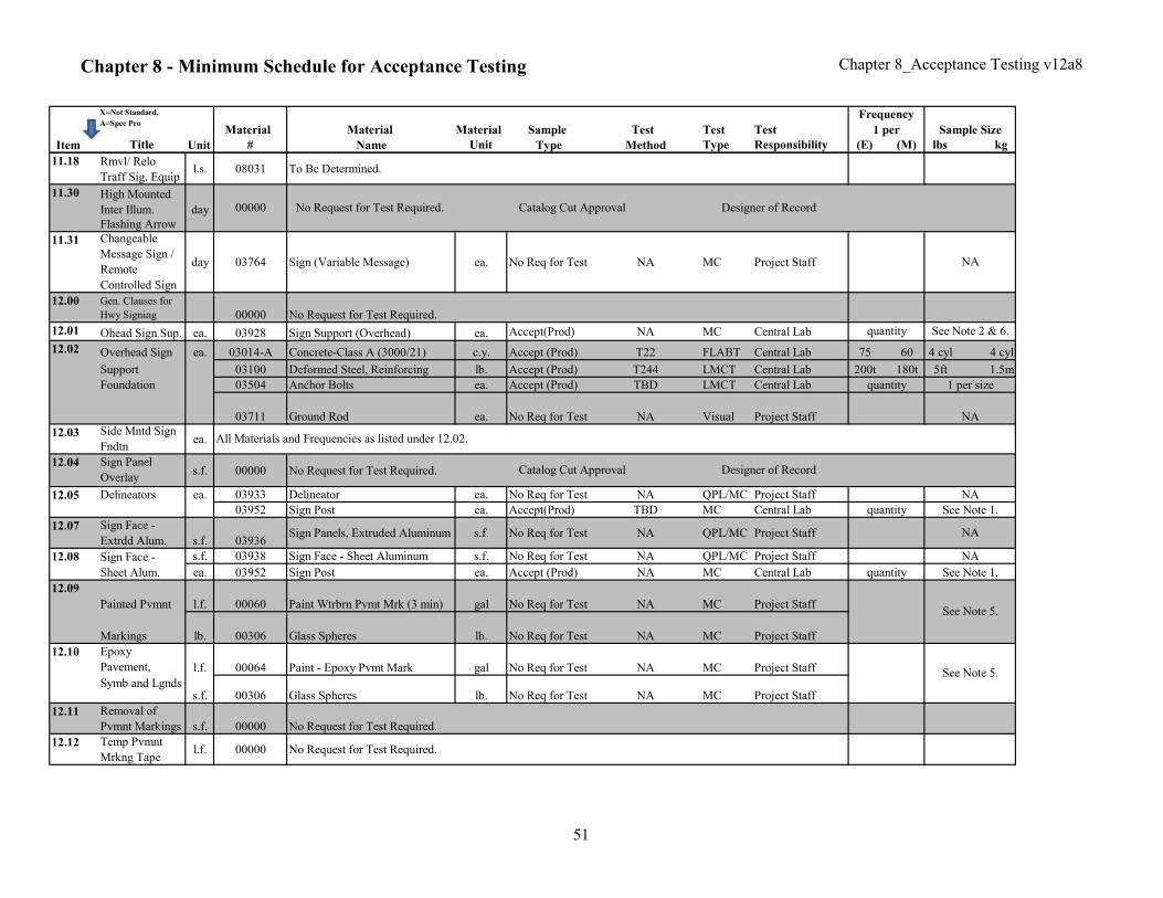
Chapter 8 - Minimum Schedule for Acceptance Testing Chapter 8_Acceptance Testing v12a8
X=Not Standard,
A=Spec ProMaterial Material Material Sample Test Test Test
Item Title Unit # Name Unit Type Method Type Responsibility (E) (M) lbs kg
Frequency
1 per Sample Size
11.18 Rmvl/ Relo
Traff Sig. Equipl.s. 08031 To Be Determined.
11.30 High Mounted
Inter Illum. day
Flashing Arrow
11.31 Changeable
Message Sign /
Remote
Controlled Sign
day 03764 Sign (Variable Message) ea. No Req for Test NA MC Project Staff
12.00 Gen. Clauses for
Hwy Signing 00000 No Request for Test Required.
12.01 Ohead Sign Sup. ea. 03928 Sign Support (Overhead) ea. Accept(Prod) NA MC Central Lab
12.02 Overhead Sign ea. 03014-A Concrete-Class A (3000/21) c.y. Accept (Prod) T22 FLABT Central Lab 75 60 4 cyl 4 cyl
Support 03100 Deformed Steel, Reinforcing lb. Accept (Prod) T244 LMCT Central Lab 200t 180t 5ft 1.5m
Foundation 03504 Anchor Bolts ea. Accept (Prod) TBD LMCT Central Lab
03711 Ground Rod ea. No Req for Test NA Visual Project Staff
12.03 Side Mntd Sign
Fndtnea.
12.04 Sign Panel
Overlays.f. 00000 No Request for Test Required.
03933 Delineator ea. No Req for Test NA QPL/MC Project Staff
03952 Sign Post ea. Accept(Prod) TBD MC Central Lab
12.07 Sign Face -
Extrdd Alum. s.f. 03936Sign Panels, Extruded Aluminum s.f. No Req for Test NA QPL/MC Project Staff
12.08 s.f. 03938 Sign Face - Sheet Aluminum s.f. No Req for Test NA QPL/MC Project Staff
ea. 03952 Sign Post ea. Accept (Prod) NA MC Central Lab
12.09
Painted Pvmnt l.f. 00060 Paint Wtrbrn Pvmt Mrk (3 min) gal No Req for Test NA MC Project Staff
Markings lb. 00306 Glass Spheres lb. No Req for Test NA MC Project Staff
12.10 Epoxy
Pavement, l.f. 00064 Paint - Epoxy Pvmt Mark gal No Req for Test NA MC Project Staff
Symb and Lgndss.f. 00306 Glass Spheres lb. No Req for Test NA MC Project Staff
12.11 Removal of
Pvmnt Markings s.f. 00000 No Request for Test Required.
12.12 Temp Pvmnt
Mrkng Tapel.f. 00000 No Request for Test Required.
12.05 Delineators ea.
00000
All Materials and Frequencies as listed under 12.02.
1 per size
See Note 1.
NA
quantity
quantity
Designer of Record
Designer of Record
See Note 5.
Sign Face -
Sheet Alum.
NA
quantity See Note 2 & 6.
See Note 1.
No Request for Test Required. Catalog Cut Approval
NA
NA
See Note 5.
NA
quantity
Catalog Cut Approval
51
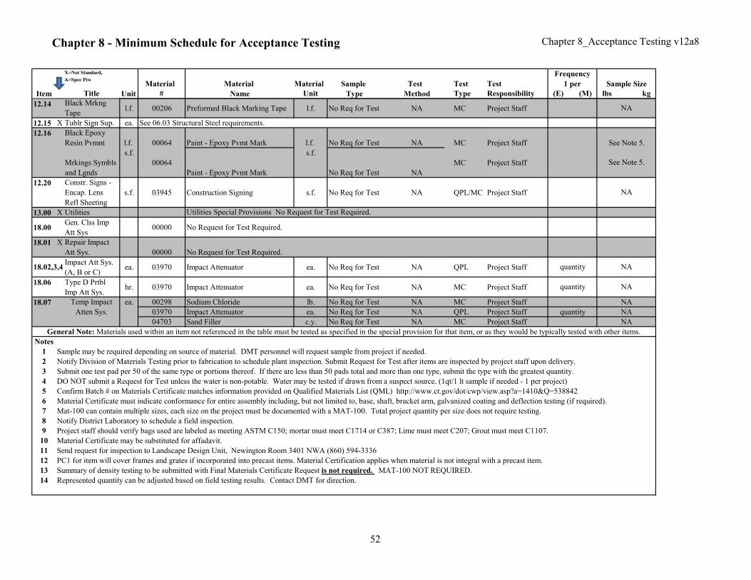
Chapter 8 - Minimum Schedule for Acceptance Testing Chapter 8_Acceptance Testing v12a8
X=Not Standard,
A=Spec ProMaterial Material Material Sample Test Test Test
Item Title Unit # Name Unit Type Method Type Responsibility (E) (M) lbs kg
Frequency
1 per Sample Size
12.14 Black Mrkng
Tapel.f. 00206 Preformed Black Marking Tape l.f. No Req for Test NA MC Project Staff
12.15 X Tublr Sign Sup. ea.
12.16 Black Epoxy
Resin Pvmnt l.f. 00064 Paint - Epoxy Pvmt Mark l.f. No Req for Test NA MC Project Staff
Mrkings Symbls
and Lgnds
s.f.
00064
Paint - Epoxy Pvmt Mark
s.f.
No Req for Test NA
MC Project Staff
12.20 Constr. Signs -
Encap. Lens
Refl Sheeting
s.f. 03945 Construction Signing s.f. No Req for Test NA QPL/MC Project Staff
13.00 X Utilities
18.00Gen. Clss Imp
Att Sys00000 No Request for Test Required.
18.01 X Repair Impact
Att Sys. 00000 No Request for Test Required.
Impact Att Sys.
(A, B or C)ea. 03970 Impact Attenuator ea. No Req for Test NA QPL Project Staff
18.06 Type D Prtbl
Imp Att Sys.hr. 03970 Impact Attenuator ea. No Req for Test NA MC Project Staff
ea. 00298 Sodium Chloride lb. No Req for Test NA MC Project Staff
03970 Impact Attenuator ea. No Req for Test NA QPL Project Staff
04703 Sand Filler c.y. No Req for Test NA MC Project Staff
Notes
1
2
3
4
5
6
7
8
9 Project staff should verify bags used are labeled as meeting ASTM C150; mortar must meet C1714 or C387; Lime must meet C207; Grout must meet C1107.
10 Material Certificate may be substituted for affadavit.
11 Send request for inspection to Landscape Design Unit, Newington Room 3401 NWA (860) 594-3336
12
13 Summary of density testing to be submitted with Final Materials Certificate Request is not required. MAT-100 NOT REQUIRED.
14 Represented quantity can be adjusted based on field testing results. Contact DMT for direction.
Notify District Laboratory to schedule a field inspection.
Temp Impact
Atten Sys.
Mat-100 can contain multiple sizes, each size on the project must be documented with a MAT-100. Total project quantity per size does not require testing.
NA
NA
DO NOT submit a Request for Test unless the water is non-potable. Water may be tested if drawn from a suspect source. (1qt/1 lt sample if needed - 1 per project)
NA
18.07
Submit one test pad per 50 of the same type or portions thereof. If there are less than 50 pads total and more than one type, submit the type with the greatest quantity.
Material Certificate must indicate conformance for entire assembly including, but not limited to, base, shaft, bracket arm, galvanized coating and deflection testing (if required).
Confirm Batch # on Materials Certificate matches information provided on Qualified Materials List (QML) http://www.ct.gov/dot/cwp/view.asp?a=1410&Q=538842
quantity
Utilities Special Provisions No Request for Test Required.
NA
See Note 5.
Sample may be required depending on source of material. DMT personnel will request sample from project if needed.
General Note: Materials used within an item not referenced in the table must be tested as specified in the special provision for that item, or as they would be typically tested with other items.
quantity
See Note 5.
NA
NA
NA
Notify Division of Materials Testing prior to fabrication to schedule plant inspection. Submit Request for Test after items are inspected by project staff upon delivery.
18.02,3,4
See 06.03 Structural Steel requirements.
quantity
PC1 for item will cover frames and grates if incorporated into precast items. Material Certification applies when material is not integral with a precast item.
52
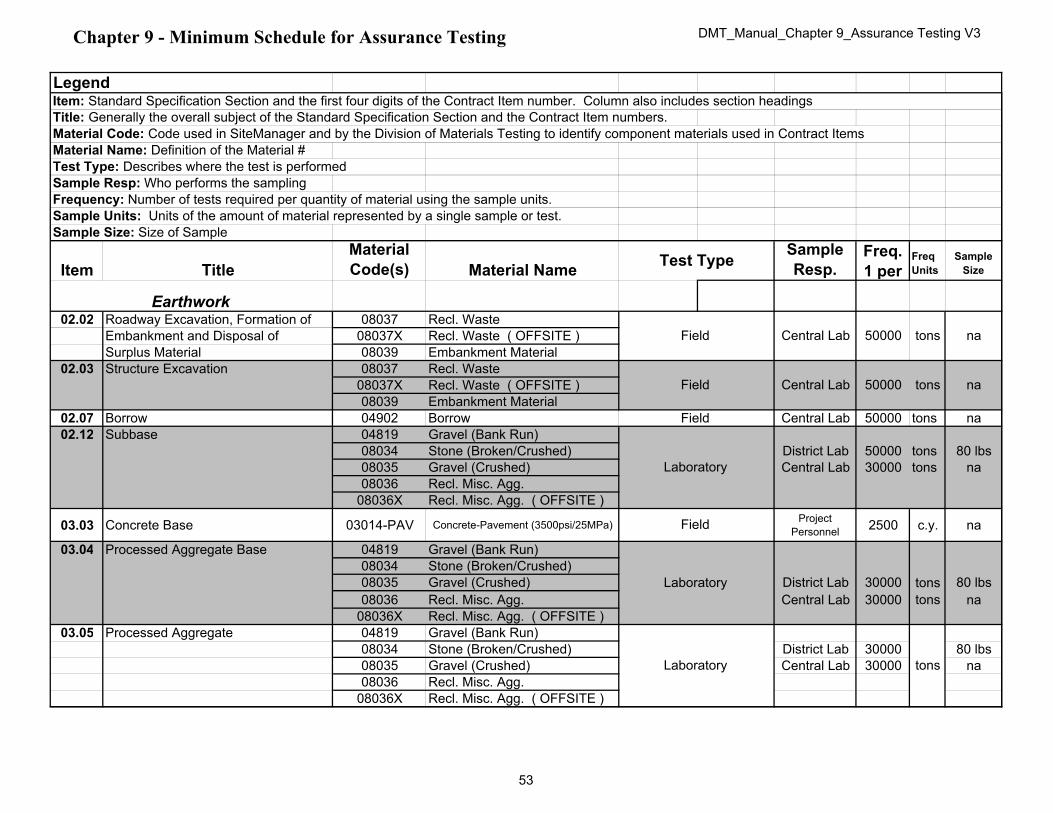
Chapter 9 - Minimum Schedule for Assurance Testing DMT_Manual_Chapter 9_Assurance Testing V3
Legend
Title: Generally the overall subject of the Standard Specification Section and the Contract Item numbers.
Material Code: Code used in SiteManager and by the Division of Materials Testing to identify component materials used in Contract Items
Material Name: Definition of the Material #
Test Type: Describes where the test is performed
Sample Resp: Who performs the sampling
Frequency: Number of tests required per quantity of material using the sample units.
Sample Units: Units of the amount of material represented by a single sample or test.
Sample Size: Size of Sample
Item Title
Material
Code(s) Material Name
Sample
Resp.Freq.
1 per Freq
Units
Sample
Size
02.02 Roadway Excavation, Formation of 08037 Recl. Waste
Embankment and Disposal of 08037X Recl. Waste ( OFFSITE )
Surplus Material 08039 Embankment Material
02.03 Structure Excavation 08037 Recl. Waste
08037X Recl. Waste ( OFFSITE )
08039 Embankment Material
02.07 Borrow 04902 Borrow Central Lab 50000 tons na
02.12 Subbase 04819 Gravel (Bank Run)
08034 Stone (Broken/Crushed) District Lab 50000 tons 80 lbs
08035 Gravel (Crushed) Central Lab 30000 tons na
08036 Recl. Misc. Agg.
08036X Recl. Misc. Agg. ( OFFSITE )
03.03 Concrete Base 03014-PAV Concrete-Pavement (3500psi/25MPa)Project
Personnel2500 c.y. na
03.04 Processed Aggregate Base 04819 Gravel (Bank Run)
08034 Stone (Broken/Crushed)
08035 Gravel (Crushed) District Lab 30000 tons 80 lbs
08036 Recl. Misc. Agg. Central Lab 30000 tons na
08036X Recl. Misc. Agg. ( OFFSITE )
03.05 Processed Aggregate 04819 Gravel (Bank Run)
08034 Stone (Broken/Crushed) District Lab 30000 80 lbs
08035 Gravel (Crushed) Central Lab 30000 na
08036 Recl. Misc. Agg.
08036X Recl. Misc. Agg. ( OFFSITE )
tonsCentral Lab
Item: Standard Specification Section and the first four digits of the Contract Item number. Column also includes section headings
na
Earthwork
tons
Test Type
Field
Field
Field
Laboratory
Field
Laboratory
Laboratory
50000
50000 na
Central Lab
tons
53
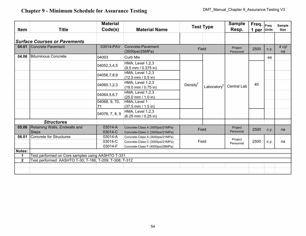
Chapter 9 - Minimum Schedule for Assurance Testing DMT_Manual_Chapter 9_Assurance Testing V3
Item Title
Material
Code(s) Material Name
Sample
Resp.Freq.
1 per Freq
Units
Sample
SizeTest Type
04.01 Concrete Pavement 03014-PAV 4 cyl
na
04.06 Bituminous Concrete 04003 Curb Mix ea
04052,3,4,5 HMA, Level 1,2,3
(9.5 mm / 0.375 in)
04056,7,8,9 HMA, Level 1,2,3
(12.5 mm / 0.5 in)
04060,1,2,3 HMA, Level 1,2,3
(19.0 mm / 0.75 in)
04064,5,6,7 HMA, Level 1,2,3
(25.0 mm / 1.0 in)04068, 9, 70,
71
HMA, Level 1
(37.5 mm / 1.5 in)
04076, 7, 8, 9 HMA, Level 1,2,3
(6.25 mm / 0.25 in)
05.06 Retaining Walls, Endwalls and 03014-A Concrete-Class A (3000psi/21MPa)
Steps 03014-C Concrete-Class C (3000psi/21MPa)
06.01 Concrete for Structures 03014-A Concrete-Class A (3000psi/21MPa)
03014-C Concrete-Class C (3000psi/21MPa)
03014-F Concrete-Class F (4000psi/28MPa)
Notes: 1
2
40
Surface Courses or Pavements
Concrete-Pavement
(3500psi/25MPa)
Project
Personnel
Project
Personnel
Field
Test performed on Core samples using AASHTO T-331.
c.y. na
na
Structures
Project
Personnel
Density1
Test performed: AASHTO T-30; T-166; T-209; T-308; T-312
c.y.Field 2500
Central Lab
Field
2500 c.y.
2500
Laboratory2
54
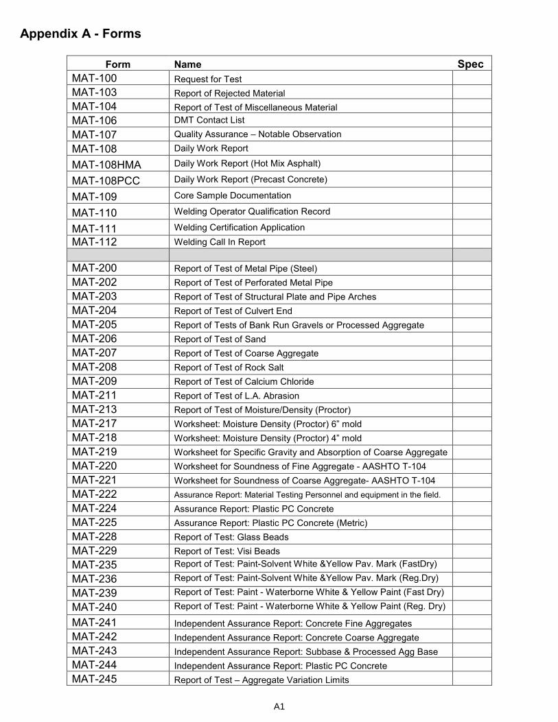
Appendix A - Forms
Form Name Spec
MAT-100 Request for Test
MAT-103 Report of Rejected Material
MAT-104 Report of Test of Miscellaneous Material
MAT-106 DMT Contact List
MAT-107 Quality Assurance – Notable Observation
MAT-108 Daily Work Report
MAT-108HMA Daily Work Report (Hot Mix Asphalt)
MAT-108PCC Daily Work Report (Precast Concrete)
MAT-109 Core Sample Documentation
MAT-110 Welding Operator Qualification Record
MAT-111 Welding Certification Application
MAT-112 Welding Call In Report
MAT-200 Report of Test of Metal Pipe (Steel)
MAT-202 Report of Test of Perforated Metal Pipe
MAT-203 Report of Test of Structural Plate and Pipe Arches
MAT-204 Report of Test of Culvert End
MAT-205 Report of Tests of Bank Run Gravels or Processed Aggregate
MAT-206 Report of Test of Sand
MAT-207 Report of Test of Coarse Aggregate
MAT-208 Report of Test of Rock Salt
MAT-209 Report of Test of Calcium Chloride
MAT-211 Report of Test of L.A. Abrasion
MAT-213 Report of Test of Moisture/Density (Proctor)
MAT-217 Worksheet: Moisture Density (Proctor) 6” mold
MAT-218 Worksheet: Moisture Density (Proctor) 4” mold
MAT-219 Worksheet for Specific Gravity and Absorption of Coarse Aggregate
MAT-220 Worksheet for Soundness of Fine Aggregate - AASHTO T-104
MAT-221 Worksheet for Soundness of Coarse Aggregate- AASHTO T-104
MAT-222 Assurance Report: Material Testing Personnel and equipment in the field.
MAT-224 Assurance Report: Plastic PC Concrete
MAT-225 Assurance Report: Plastic PC Concrete (Metric)
MAT-228 Report of Test: Glass Beads
MAT-229 Report of Test: Visi Beads
MAT-235 Report of Test: Paint-Solvent White &Yellow Pav. Mark (FastDry)
MAT-236 Report of Test: Paint-Solvent White &Yellow Pav. Mark (Reg.Dry)
MAT-239 Report of Test: Paint - Waterborne White & Yellow Paint (Fast Dry)
MAT-240 Report of Test: Paint - Waterborne White & Yellow Paint (Reg. Dry)
MAT-241 Independent Assurance Report: Concrete Fine Aggregates
MAT-242 Independent Assurance Report: Concrete Coarse Aggregate
MAT-243 Independent Assurance Report: Subbase & Processed Agg Base
MAT-244 Independent Assurance Report: Plastic PC Concrete
MAT-245 Report of Test – Aggregate Variation Limits
A1

MAT-246 Tracking Report: Asphaltic Plug Joint
MAT-248 Tracking Report: Pavement Marking Materials
MAT-300 Report of Test: Anchor Bolts (Straight)
MAT-301 Report of Test: Anchor Bolts (w/Hook)
MAT-302 Report of Test: Hex Bolt
MAT-303 Report of Test: Chain Link Fence Fabric 4.58
MAT-304 Report of Test: Reinforced Concrete Pipe
MAT-305 Report of Test: Steel Bars and Shapes
MAT-306 Report of Test: Steel Fabric Reinforcement
MAT-307 Report of Test: General Tensile Strength
MAT-308 Report for Test on Cylinders
MAT-308A Report of Test on Cylinder Diameter
MAT-309 Report of Test: Masonry Concrete Units 4.48
MAT-310 Report of Test: Elastomeric Bearing Pad
MAT-312 Report of Test: Clay Brick 4.48
MAT-313 Report of Test: Concrete Block for Slope Protection
MAT-314 Certification of Precast Concrete Prod.
MAT-316 Report of Test: Portland Cement (All Types)
MAT-323 Report of Test: Steel Strand 4.25
MAT-324 Field Report : Yearly inspection for certification of prestress/precast concrete and pipe manufacturers
MAT-325 Report of Test: Chain Link Fence Hardware
MAT-326 Report of Test: Chain Link Fence Tension Wire
MAT-327 Report of Test: H-Piles and Wide Flange Shapes
MAT-328 Report of Test: Deformed Steel Wire for Concrete Reinforcement
MAT-329 Certification of Brand Registry
MAT-330 Guideline: Visual Inspection of Reinforcing Steel
MAT-401 Report of Test: Asphalt Binder
MAT-402 Report of Test: Emulsified Asphalts
MAT-404 Field Report: Bituminous Concrete Plant Inspection
MAT-406 Field Report: Inspection of HMA Field Laboratory
MAT-407 Field Report: Plant and Laboratory Deficiency Report
MAT-408 Field Report: QA Verification Form
MAT-412cm Report of Test: Bituminous Curb Mix Quality
MAT412S Report of Test: Bituminous SuperPave Quality (2 sided)
MAT-412s-ppt Report of Test: Bituminous SuperPave Quality (Pre-Production Trial)
MAT-412ut Report of Test: Bituminous Ultrathin Quality
MAT-417 Worksheet: Random Lot Selection at Plant
MAT-418 Worksheet: Job Mix Formula Verification
MAT-419 Template: Quality Control Plan for Fine Aggregate. used in HMA.
MAT-429cm Template: Job Mix Formula (curb mix)
MAT-429s Template: Job Mix Formula (SuperPave)
MAT-429ut Template: Job Mix Formula (Ultrathin)
A2

MAT-433 Worksheet: Ignition Oven Correction
MAT-438NonPWL Worksheet: Daily Plant Adjustment (Non-PWL Lots)
MAT-438PWL Worksheet: Daily Plant Adjustment (PWL Lots)
MAT-440 Field Report: Producer Facility Mix Design Status
MAT-600 Report of Witness Test – HMA Independent Assurance
A3
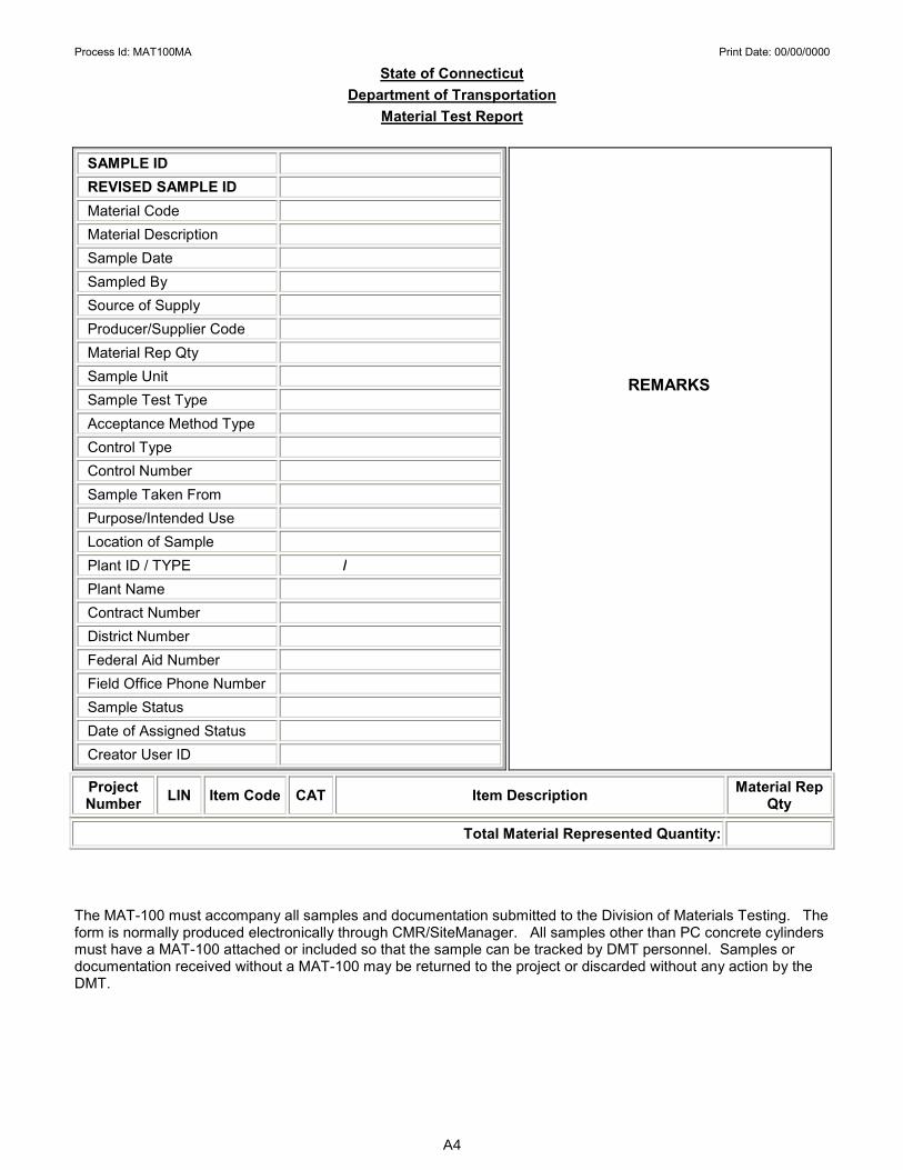
Process Id: MAT100MA Print Date: 00/00/0000
State of Connecticut
Department of Transportation
Material Test Report
SAMPLE ID
REVISED SAMPLE ID
Material Code
Material Description
Sample Date
Sampled By
Source of Supply
Producer/Supplier Code
Material Rep Qty
Sample Unit
Sample Test Type
Acceptance Method Type
Control Type
Control Number
Sample Taken From
Purpose/Intended Use
Location of Sample
Plant ID / TYPE /
Plant Name
Contract Number
District Number
Federal Aid Number
Field Office Phone Number
Sample Status
Date of Assigned Status
Creator User ID
Project Number
LIN Item Code CAT Item Description Material Rep
Qty
Total Material Represented Quantity:
The MAT-100 must accompany all samples and documentation submitted to the Division of Materials Testing. The form is normally produced electronically through CMR/SiteManager. All samples other than PC concrete cylinders must have a MAT-100 attached or included so that the sample can be tracked by DMT personnel. Samples or documentation received without a MAT-100 may be returned to the project or discarded without any action by the DMT.
REMARKS
A4

STATE OF CONNECTICUT - DEPARTMENT OF TRANSPORTATION
DIVISION OF MATERIALS TESTING
MAT-103 REV 11/16 REPORT OF REJECTED MATERIAL
Project Number ITEM # (If multiple, only list first from MAT-100) Date
Material Sample ID.
Source of Material Quantity Represented Reason for Rejection
Complete section 1 OR 2. See below for instructions.
1. ACTION TAKEN - DOES NOT INCLUDE RETESTING THE SAME MATERIAL WITH A DIFFERENT TEST METHOD.
(i.e., Windsor Probe, Swiss Hammer)
New Sample Source Sample ID. Sample Status
Material Replaced Source Sample ID. Sample Status
Signature
Inspector Print
Project Engineer Print
District or Assistant District Engineer Print
Town Official/Title (municipal projects only) Print
2. ACCEPTANCE OF REJECTED MATERIAL WITHOUT ACTIONIn accordance with ConnDOT Standard Specifications Section 1.06.02 or
1.06.04, the non-complying material is hereby accepted by the District.
Section Applied
1.06.02 1.06.04
Check one
Signature/Print
Inspector Print
Project Engineer Print
District or Assistant District Engineer Print
Town Official/Title (Municipal P rojects Only) Print
For acceptance by Section 1.06.02, all the following criteria must be met.
1. Results of prior and subsequent series of tests of the material or materials from the same source or sources are foundsatisfactory.
2. The incidence and degree of non-conformance with the Contract requirements are, in the Engineer's judgement, withinreasonable limits.
3. The Contractor, in the Engineer's judgement, had diligently exercised material controls consistent with good practices.
4. No adverse effect on the value or serviceability of the completed work could result.
For acceptance by Section 1.06.04, any credits, allowances, warranties, or other conditions of acceptance
must be described below.
Orig - Division of Materials Testing Copy -District Copy - Project Records
A5

Report of Rejected Material (MAT-103) Instructions
The Report of Rejected Material form serves the following purpose:
1. Identify the project and material that did not meet specification.
2. Report action taken (if any) which only includes retesting the material with an additional sample and achieving acceptable results or removing and replacing the deficient material with acceptable material. When such an action is taken, the MAT-103 provides the DMT with information on how rejected material was addressed. Signatures are required in this section to acknowledge the rejection and the action taken.
Please Note: Portland Cement (PC) Concrete is recommended for acceptance or rejection based on concrete cylinder test results at 28 days of age. Windsor Probe or Swiss Hammer results are for information only and will not override the test cylinder results at 28 days regardless of when they are performed. The PC concrete will be listed as an exception to the specifications on the Final Materials Certificate unless the District accepts the concrete using the acceptance criteria described below.
3. In the case where no action was taken, the District may formally accept the non-complying or deficient material in accordance with Sections 1.06.02 or 1.06.04. Signatures in this section are intended for formal acceptance of the non-complying or deficient material by the District. In the case where a Town Official or Consulting Engineer accepts material, if the District agrees, it must formally concur with the signatures. The DMT may still take exception to the District acceptance and list the material as an exception to the specification on the Final Materials Certificate if it is unable to concur.
MAT-104 REPORT OF TEST MISCELLANEOUS MATERIAL
STATE OF CONNECTICUT DEPARTMENT OF TRANSPORTATION
BUREAU OF HIGHWAYS REPORT OF TEST OF MISCELLANEOUS MATERIAL
MAT 104 Revised July 2003
DATE
PROJECT/SAMPLE NO.
LABORATORY NO.
RECOMMENDED FOR
REMARKS
The MAT-104 will be used by DMT personnel to report the results of testing on materials that are not otherwise covered by any specific reporting form.
A6
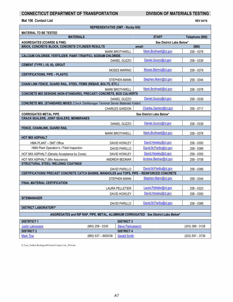
CONNECTICUT DEPARTMENT OF TRANSPORTATION DIVISION OF MATERIALS TESTING
Mat 106 Contact List REV 04/16
REPRESENTATIVE (DMT - Rocky Hill)
MATERIAL TO BE TESTED
MATERIALS STAFF Telephone (860)
AGGREGATES (COARSE & FINE) See District Labs Below*
BRICK, CONCRETE BLOCK, CONCRETE CYLINDER RESULTS email: (860)
MARK BROTHWELL [email protected] 258 - 0378
CALCIUM CHLORIDE, FERTILIZER, PAINT (TRAFFIC), SODIUM CHLORIDE,
DANIEL GUZZO [email protected] 258 - 0339
CEMENT (TYPE I, I/II, III), GROUT
MOSES MARINO [email protected] 258 - 0379
CERTIFICATIONS, PIPE – PLASTIC
STEPHEN MANN [email protected] 258 - 0344
CHAIN LINK FENCE, GUARD RAIL, STEEL ITEMS (REBAR, BOLTS, ETC.)
MARK BROTHWELL [email protected] 258 - 0378
CONCRETE MIX DESIGNS (NON-STANDARD), PRECAST/ CONCRETE, BOX CULVERTS
DANIEL GUZZO [email protected] 258 - 0339
CONCRETE MIX, (STANDARD) MIXES (Check SiteManager Terminal Server Materials Folder)
CHARLES GARDON [email protected] 258 - 0717
CORROGATED METAL PIPE See District Labs Below*
CRACK SEALERS, JOINT SEALERS, MEMBRANES
DANIEL GUZZO [email protected] 258 - 0339
FENCE, CHAINLINK, GUARD RAIL
MARK BROTHWELL [email protected] 258 - 0378
HOT MIX ASPHALT
HMA PLANT – DMT Office DAVID HOWLEY [email protected] 258 - 0350
HMA Plant Operation’s / Field Inspection DAVID PARILLO [email protected] 258 - 0389
HOT MIX ASPHALT (Density Acceptance by Cores) DAVID HOWLEY [email protected] 258 - 0350
HOT MIX ASPHALT (Mix Assurance) ANDREW BEDNAR [email protected] 258 - 0708
STRUCTURAL STEEL/ WELDING/ COATINGS
DAVID PARILLO [email protected] 258 - 0389
CERTIFICATIONS/ PRECAST CONCRETE CATCH BASINS, MANHOLES and TOPS, PIPE – REINFORCED CONCRETE
STEPHEN MANN [email protected] 258 - 0344
FINAL MATERIAL CERTIFICATION
LAURA PELLETIER [email protected] 258 - 0323
DAVID HOWLEY [email protected] 258 - 0350
SITEMANAGER
DAVID PARILLO [email protected] 258 - 0389
DISTRICT LABORATORY*
AGGREGATES and RIP RAP, PIPE, METAL, ALUMINUM CORRUGATED See District Labs Below*
DISTRTICT 1 DISTRICT 3
Justin Labossiere (860) 258 - 0335 Steve Parkosewich (203) 389 - 3128
DISTRICT 2 DISTRICT 4
Mark Tice (860) 537 – 8935/36 Gerald Smith (203) 591 - 3739
S:\User_Folders\RodriguesR\Forms\Contact List_2016.doc
A7
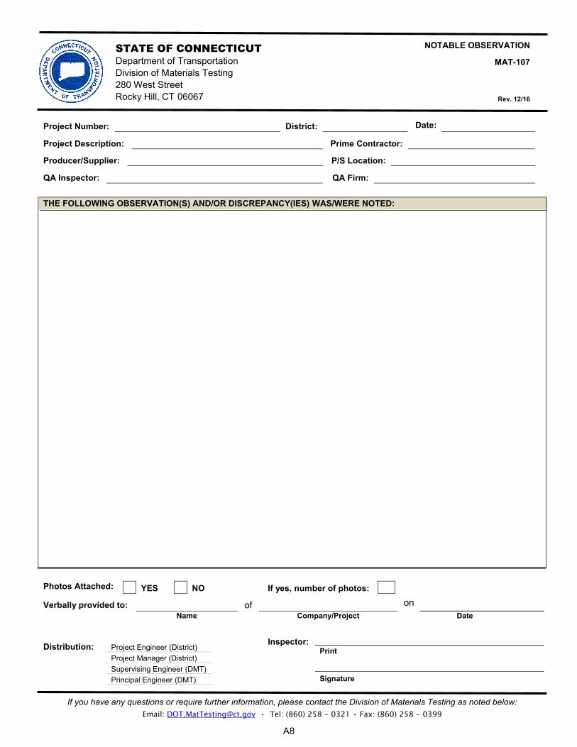
STATE OF CONNECTICUT NOTABLE OBSERVATION
MAT-107 Department of Transportation
Division of Materials Testing 280 West Street
Rocky Hill, CT 06067 Rev. 12/16
If you have any questions or require further information, please contact the Division of Materials Testing as noted below: Email: [email protected] • Tel: (860) 258 - 0321 • Fax: (860) 258 - 0399
Project Number: District: Date::
Project Description: Prime Contractor:
Producer/Supplier: P/S Location:
QA Inspector: QA Firm:
THE FOLLOWING OBSERVATION(S) AND/OR DISCREPANCY(IES) WAS/WERE NOTED:
YES NO If yes, number of photos: Photos Attached:
Verbally provided to: of on
Name Date Company/Project
PrintDistribution: Project Engineer (District)
Project Manager (District)
Supervising Engineer (DMT)
Signature Principal Engineer (DMT)
Inspector:
A8
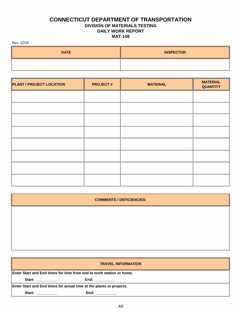
Rev. 12/16
PLANT / PROJECT LOCATION PROJECT # MATERIALMATERIAL
QUANTITY
DATE
DAILY WORK REPORT
CONNECTICUT DEPARTMENT OF TRANSPORTATIONDIVISION OF MATERIALS TESTING
MAT-108
INSPECTOR
Start: __________ End: __________
Enter Start and End times for actual time at the plants or projects.
Start: __________ End: __________
COMMENTS / DEFICIENCIES:
TRAVEL INFORMATION
Enter Start and End times for time from and to work station or home.
A9

Material
CodeRAP WMA Contract
Mix Status On
Departure
State
Test
Load
#IA
Load
#
End:
End:
� AASHTO TESTS WITNESSED
Verify plant settings are in accordance with JMF.
CONNECTICUT DEPARTMENT OF TRANSPORTATION
DIVISION OF MATERIALS TESTING
HMA INSPECTOR'S REPORT REV. 12/16 MAT-108 HMA
PLANT TECHNICIAN:
R 47 - Sample Reduction
T 168 - Sampling Bituminous Mixtures
T 209 - Theoretical Maximum Gravity (Gmm)
T 308 - Asphalt Content - Ignition Sample
T 312 - Preparation of Gyratory Sample
T 30 - Sieve Analysis
T 166 - Bulk Specific Gravity (Gmb)
T 255 - Moisture Content
COMMENTS / DEFICIENCIES:
Start:
Start:
Verify the use of anti-strip if required by JMF.
Inspect aggregate and RAP stockpiles.
Testing equipment is functioning properly.
Vacation / Sick / PL:
Verify proper PG Binder in accordance with JMF & Contract.
Check the temperature of the mix.
Enter Start & End times for actual time at Plant.
Regular Hours:
Overtime Hours:
Material
Description
Town
Total Shift Hours:Enter Start & End times from and to work station or home.
Inspect haul units for proper canvas covers and release agents.
Technician performed Quality Control testing (aggregates, HMA, etc.).
� ADDITIONAL INFORMATION
PLANT #:
PRODUCER NAME:
DATE:
STATE INSPECTOR:
LOCATION:
Route
Project #
A10

STATE OF CONNECTICUT
DEPARTMENT OF TRANSPORTATION
DIVISION OF MATERIALS TESTING
PORTLAND CEMENT CONCRETE (PCC) INSPECTOR’S DAILY WORK REPORT
MAT-108 PCC
Rev. 12-16
PLANT INFORMATION DATE:
PLANT NAME:
LOCATION:
PLANT MANAGER & PHONE NUMBER:
INSPECTOR’S NAME:
PROJECT #:
ITEM BEING INSPECTED ITEM DESCRIPTION:
FORM INSPECTED BY:
DID FORM MEET REQUIREMENTS? Yes No
NON CONFORMANCE:
REMARKS:
CONCRETE POUR TIME:
TEMP. OF CONCRETE:
TEMP. OF BUILDING:
AIR:
SLUMP:
DID CONCRETE POUR MEET REQUIREMENTS? Yes No
NON CONFORMANCE:
REMARKS:
WITNESS CYLINDER BREAKS BREAKS:
DID BREAKS MEET REQUIREMENTS? Yes No
NON CONFORMANCE:
REMARKS:
END OF DAY REMARKS
TRAVEL INFORMATION
Enter Start and End times for time from and to work station or home.
Start: __________ End: __________
Enter Start and End times for actual time at the plants or projects.
Start: __________ End: __________
A11
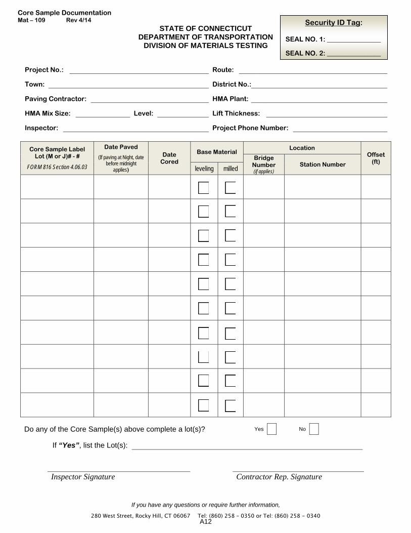
STATE OF CONNECTICUT DEPARTMENT OF TRANSPORTATION
DIVISION OF MATERIALS TESTING
If you have any questions or require further information,
280 West Street, Rocky Hill, CT 06067 � Tel: (860) 258 – 0350 or Tel: (860) 258 - 0340
Project No.: Route:
Town: District No.:
Paving Contractor: HMA Plant:
HMA Mix Size: Level: Lift Thickness:
Inspector: Project Phone Number:
Core Sample Label Lot (M or J)# - #
FORM 816 Section 4.06.03
Date Paved
(If paving at Night, date before midnight
applies)
Date Cored
Base Material Location
Offset (ft) Bridge
Number (if applies)
Station Number leveling milled
Do any of the Core Sample(s) above complete a lot(s)? Yes No
If “Yes”, list the Lot(s):
Inspector Signature Contractor Rep. Signature
Core Sample Documentation Mat – 109 Rev 4/14 Security ID Tag:
SEAL NO. 1: ________________ SEAL NO. 2: ________________
A12
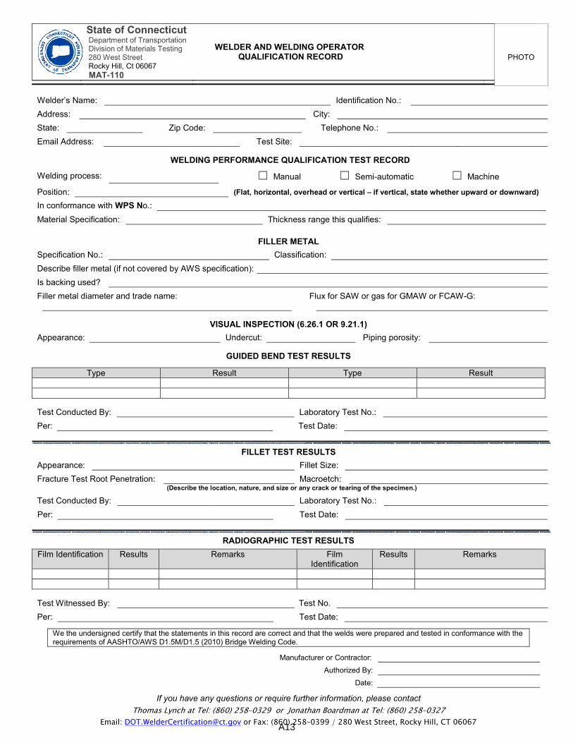
State of Connecticut Department of Transportation Division of Materials Testing 280 West Street Rocky Hill, Ct 06067
MAT-110
WELDER AND WELDING OPERATOR QUALIFICATION RECORD
If you have any questions or require further information, please contact
Thomas Lynch at Tel: (860) 258–0329 or Jonathan Boardman at Tel: (860) 258–0327
Email: [email protected] or Fax: (860) 258–0399 / 280 West Street, Rocky Hill, CT 06067
PHOTO
Welder’s Name: Identification No.:
Address: City:
State: Zip Code: Telephone No.:
Email Address: Test Site:
WELDING PERFORMANCE QUALIFICATION TEST RECORD
Welding process: ☐ Manual ☐ Semi-automatic ☐ Machine
Position: (Flat, horizontal, overhead or vertical – if vertical, state whether upward or downward)
In conformance with WPS No.:
Material Specification: Thickness range this qualifies:
FILLER METAL
Specification No.: Classification:
Describe filler metal (if not covered by AWS specification):
Is backing used?
Filler metal diameter and trade name: Flux for SAW or gas for GMAW or FCAW-G:
VISUAL INSPECTION (6.26.1 OR 9.21.1)
Appearance: Undercut: Piping porosity:
GUIDED BEND TEST RESULTS
Type Result Type Result
Test Conducted By: Laboratory Test No.:
Per: Test Date:
FILLET TEST RESULTS
Appearance: Fillet Size:
Fracture Test Root Penetration: Macroetch: (Describe the location, nature, and size or any crack or tearing of the specimen.)
Test Conducted By: Laboratory Test No.:
Per: Test Date:
RADIOGRAPHIC TEST RESULTS
Film Identification Results Remarks Film Identification
Results Remarks
Test Witnessed By: Test No.
Per: Test Date:
We the undersigned certify that the statements in this record are correct and that the welds were prepared and tested in conformance with the requirements of AASHTO/AWS D1.5M/D1.5 (2010) Bridge Welding Code.
Manufacturer or Contractor:
Authorized By:
Date:
A13
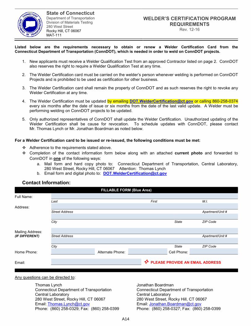
State of Connecticut Department of Transportation Division of Materials Testing 280 West Street Rocky Hill, CT 06067 MAT-111
WELDER’S CERTIFICATION PROGRAM REQUIREMENTS
Rev. 12-16
Listed below are the requirements necessary to obtain or renew a Welder Certification Card from the Connecticut Department of Transportation (ConnDOT), which is needed in order to weld on ConnDOT projects.
1. New applicants must receive a Welder Qualification Test from an approved Contractor listed on page 2. ConnDOT also reserves the right to require a Welder Qualification Test at any time.
2. The Welder Certification card must be carried on the welder’s person whenever welding is performed on ConnDOT Projects and is prohibited to be used as certification for other business.
3. The Welder Certification card shall remain the property of ConnDOT and as such reserves the right to revoke any Welder Certification at any time.
4. The Welder Certification must be updated by emailing [email protected] or calling 860-258-0374 every six months after the date of issue or six months from the date of the last valid update. A Welder must be performing welding on ConnDOT projects to be updated.
5. Only authorized representatives of ConnDOT shall update the Welder Certification. Unauthorized updating of the Welder Certification shall be cause for revocation. To schedule updates with ConnDOT, please contact Mr. Thomas Lynch or Mr. Jonathan Boardman as noted below.
For a Welder Certification card to be issued or re-issued, the following conditions must be met:
� Adherence to the requirements stated above.
� Completion of the contact information form below along with an attached current photo and forwarded to
ConnDOT in one of the following ways:
a. Mail form and hard copy photo to: Connecticut Department of Transportation, Central Laboratory, 280 West Street, Rocky Hill, CT 06067 Attention: Thomas Lynch
b. Email form and digital photo to: [email protected]
Contact Information:
FILLABLE FORM (Blue Area)
Full Name:
Last First M.I.
Address:
Street Address Apartment/Unit #
City State ZIP Code
Mailing Address: (IF DIFFERENT) Street Address Apartment/Unit #
City State ZIP Code
Home Phone: Alternate Phone: Cell Phone:
Email: � PLEASE PROVIDE AN EMAIL ADDRESS
Any questions can be directed to:
Thomas Lynch Connecticut Department of Transportation Central Laboratory 280 West Street, Rocky Hill, CT 06067 Email: [email protected] Phone: (860) 258-0329; Fax: (860) 258-0399
Jonathan Boardman Connecticut Department of Transportation Central Laboratory 280 West Street, Rocky Hill, CT 06067 Email: [email protected] Phone: (860) 258-0327; Fax: (860) 258-0399
A14
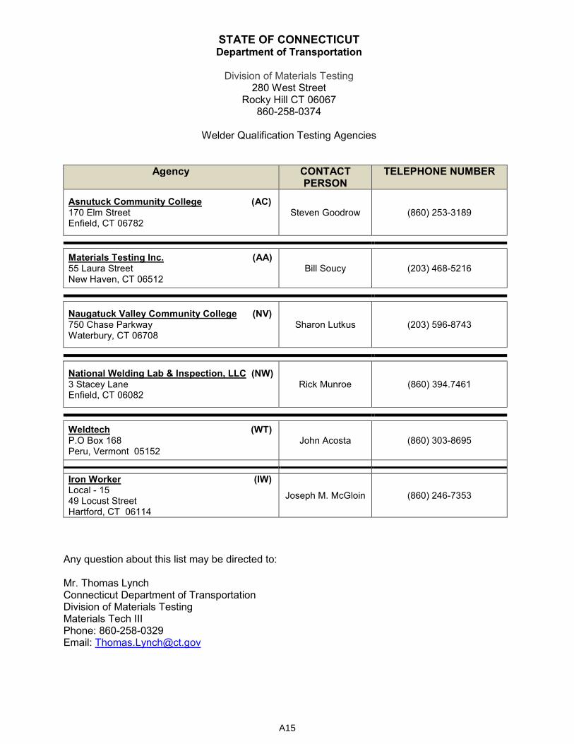
STATE OF CONNECTICUT Department of Transportation
Division of Materials Testing
280 West Street Rocky Hill CT 06067
860-258-0374
Welder Qualification Testing Agencies
Agency CONTACT PERSON
TELEPHONE NUMBER
Asnutuck Community College (AC) 170 Elm Street Enfield, CT 06782
Steven Goodrow (860) 253-3189
Materials Testing Inc. (AA) 55 Laura Street New Haven, CT 06512
Bill Soucy (203) 468-5216
Naugatuck Valley Community College (NV) 750 Chase Parkway Waterbury, CT 06708
Sharon Lutkus (203) 596-8743
National Welding Lab & Inspection, LLC (NW) 3 Stacey Lane Enfield, CT 06082
Rick Munroe (860) 394.7461
Weldtech (WT) P.O Box 168 Peru, Vermont 05152
John Acosta (860) 303-8695
Iron Worker (IW) Local - 15 49 Locust Street Hartford, CT 06114
Joseph M. McGloin (860) 246-7353
Any question about this list may be directed to: Mr. Thomas Lynch Connecticut Department of Transportation Division of Materials Testing Materials Tech III Phone: 860-258-0329 Email: [email protected]
A15
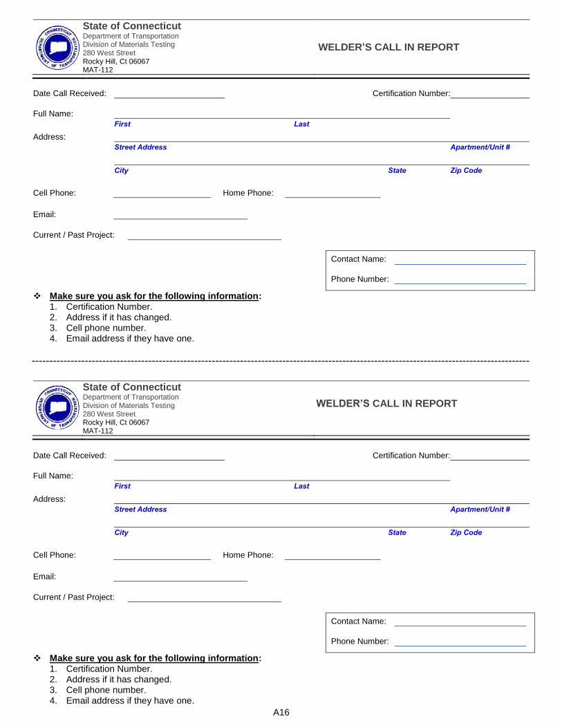
State of ConnecticutDepartment of Transportation Division of Materials Testing 280 West Street Rocky Hill, Ct 06067 MAT-112
WELDER’S CALL IN REPORT
Date Call Received: Certification Number:
Full Name:
First Last
Address:
Street Address Apartment/Unit #
City State Zip Code
Cell Phone: Home Phone:
Email:
Current / Past Project:
Contact Name:
Phone Number:
Make sure you ask for the following information:1. Certification Number.2. Address if it has changed.3. Cell phone number.4. Email address if they have one.
A16
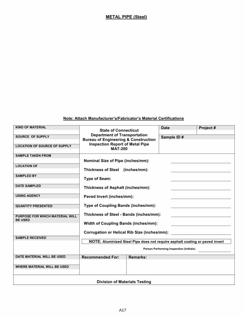
METAL PIPE (Steel)
Note: Attach Manufacturer’s/Fabricator’s Material Certifications
KIND OF MATERIAL State of Connecticut
Department of Transportation Bureau of Engineering & Construction
Inspection Report of Metal Pipe MAT-200
Date Project # SOURCE OF SUPPLY Sample ID #
LOCATION OF SOURCE OF SUPPLY
SAMPLE TAKEN FROM Nominal Size of Pipe (inches/mm):
Thickness of Steel (inches/mm):
Type of Seam:
Thickness of Asphalt (inches/mm):
Paved Invert (inches/mm):
Type of Coupling Bands (inches/mm):
Thickness of Steel - Bands (inches/mm):
Width of Coupling Bands (inches/mm):
Corrugation or Helical Rib Size (inches/mm):
NOTE: Aluminized Steel Pipe does not require asphalt coating or paved invert
Person Performing Inspection (Initials):
LOCATION OF
SAMPLED BY
DATE SAMPLED
USING AGENCY
QUANTITY PRESENTED
PURPOSE FOR WHICH MATERIAL WILL BE USED
SAMPLE RECEIVED
DATE MATERIAL WILL BE USED Recommended For: Remarks:
WHERE MATERIAL WILL BE USED
Division of Materials Testing
A17

PERFORATED METAL PIPE (Steel)
Note: Attach Manufacturer’s/Fabricator’s Material Certifications
KIND OF MATERIAL
State of Connecticut Department of Transportation
Bureau of Engineering & Construction Inspection Report of Perforated Metal Pipe
MAT-202
Date Project #
SOURCE OF SUPPLY Sample ID #
LOCATION OF SOURCE OF SUPPLY
SAMPLE TAKEN FROM Nominal Size of Pipe (inches/mm):
Thickness of Steel (inches/mm):
Type of Seam:
Number of Rows of Perforations:
Diameter of Perforations (inches/mm):
Height of Uppermost Rows of Perforations Above bottom of Invert (inches/mm):
Chord Length of Unperforated Segment (inches/mm):
Type of Coupling Bands:
Thickness of Steel Bands (inches/mm):
Width of Coupling Bands (inches/mm):
Corrugation or Helical Rib Size (inches/mm):
Person Performing Inspection (initials) :
LOCATION OF
SAMPLED BY
DATE SAMPLED
USING AGENCY
QUANTITY PRESENTED
PURPOSE FOR WHICH MATERIAL WILL BE USED
SAMPLE RECEIVED
DATE MATERIAL WILL BE USED
WHERE MATERIAL WILL BE USED
Recommended For Remarks
Division of Materials Testing
A18
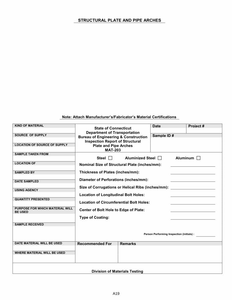
STRUCTURAL PLATE AND PIPE ARCHES
Note: Attach Manufacturer’s/Fabricator’s Material Certifications
KIND OF MATERIAL
State of Connecticut Department of Transportation
Bureau of Engineering & Construction Inspection Report of Structural
Plate and Pipe Arches MAT-203
Date Project # SOURCE OF SUPPLY Sample ID #
LOCATION OF SOURCE OF SUPPLY
SAMPLE TAKEN FROM
Steel Aluminized Steel Aluminum
Nominal Size of Structural Plate (inches/mm):
Thickness of Plates (inches/mm):
Diameter of Perforations (inches/mm):
Size of Corrugations or Helical Ribs (inches/mm):
Location of Longitudinal Bolt Holes:
Location of Circumferential Bolt Holes:
Center of Bolt Hole to Edge of Plate:
Type of Coating:
Person Performing Inspection (initials) :
LOCATION OF
SAMPLED BY
DATE SAMPLED
USING AGENCY
QUANTITY PRESENTED
PURPOSE FOR WHICH MATERIAL WILL BE USED
SAMPLE RECEIVED
DATE MATERIAL WILL BE USED Recommended For Remarks
WHERE MATERIAL WILL BE USED
Division of Materials Testing
A19
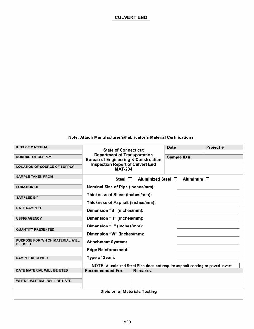
CULVERT END
Note: Attach Manufacturer’s/Fabricator’s Material Certifications
KIND OF MATERIAL
State of Connecticut Department of Transportation
Bureau of Engineering & Construction Inspection Report of Culvert End
MAT-204
Date Project # SOURCE OF SUPPLY Sample ID #
LOCATION OF SOURCE OF SUPPLY
SAMPLE TAKEN FROM
Steel Aluminized Steel Aluminum
Nominal Size of Pipe (inches/mm):
Thickness of Sheet (inches/mm):
Thickness of Asphalt (inches/mm):
Dimension “B” (inches/mm):
Dimension “H” (inches/mm):
Dimension “L” (inches/mm):
Dimension “W” (inches/mm):
Attachment System:
Edge Reinforcement:
Type of Seam:
NOTE: Aluminized Steel Pipe does not require asphalt coating or paved invert.
LOCATION OF
SAMPLED BY
DATE SAMPLED
USING AGENCY
QUANTITY PRESENTED
PURPOSE FOR WHICH MATERIAL WILL BE USED
SAMPLE RECEIVED
DATE MATERIAL WILL BE USED Recommended For: Remarks:
WHERE MATERIAL WILL BE USED
Division of Materials Testing
A20
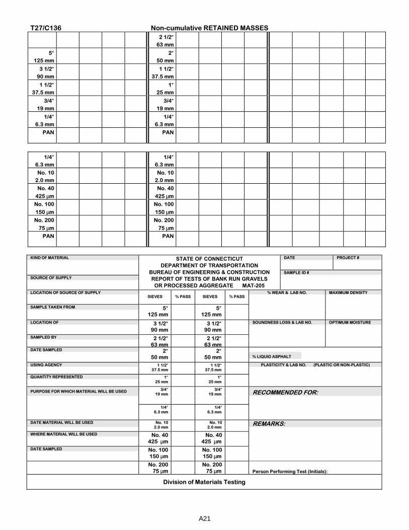
T27/C136 Non-cumulative RETAINED MASSES
2 1/2″
63 mm
5″
125 mm
2″
50 mm
3 1/2″
90 mm
1 1/2″
37.5 mm
1 1/2″
37.5 mm
1″
25 mm
3/4″
19 mm
3/4″
19 mm
1/4″
6.3 mm
1/4″
6.3 mm
PAN
PAN
1/4″
6.3 mm
1/4″
6.3 mm
No. 10
2.0 mm
No. 10
2.0 mm
No. 40
425 µm
No. 40
425 µm
No. 100
150 µm
No. 100
150 µm
No. 200
75 µm
No. 200
75 µm
PAN
PAN
KIND OF MATERIAL STATE OF CONNECTICUT
DEPARTMENT OF TRANSPORTATION BUREAU OF ENGINEERING & CONSTRUCTION REPORT OF TESTS OF BANK RUN GRAVELS
OR PROCESSED AGGREGATE MAT-205
DATE PROJECT #
SAMPLE ID #
SOURCE OF SUPPLY
LOCATION OF SOURCE OF SUPPLY
SIEVES % PASS SIEVES % PASS % WEAR & LAB NO. MAXIMUM DENSITY
SAMPLE TAKEN FROM 5″ 125 mm
5″ 125 mm
LOCATION OF 3 1/2″ 90 mm
3 1/2″ 90 mm
SOUNDNESS LOSS & LAB NO. OPTIMUM MOISTURE
SAMPLED BY 2 1/2″
63 mm
2 1/2″
63 mm
DATE SAMPLED 2″
50 mm 2″
50 mm % LIQUID ASPHALT
USING AGENCY 1 1/2″ 37.5 mm
1 1/2″ 37.5 mm
PLASTICITY & LAB NO. (PLASTIC OR NON-PLASTIC)
QUANTITY REPRESENTED 1″
25 mm 1″
25 mm PURPOSE FOR WHICH MATERIAL WILL BE USED
3/4″ 19 mm
3/4″ 19 mm
RECOMMENDED FOR:
1/4″ 6.3 mm
1/4″ 6.3 mm
DATE MATERIAL WILL BE USED No. 10 2.0 mm
No. 10 2.0 mm REMARKS:
WHERE MATERIAL WILL BE USED No. 40
425 µm No. 40
425 µm DATE SAMPLED No. 100
150 µm No. 100
150 µm No. 200
75 µm
No. 200
75 µm
Person Performing Test (Initials):
Division of Materials Testing
A21
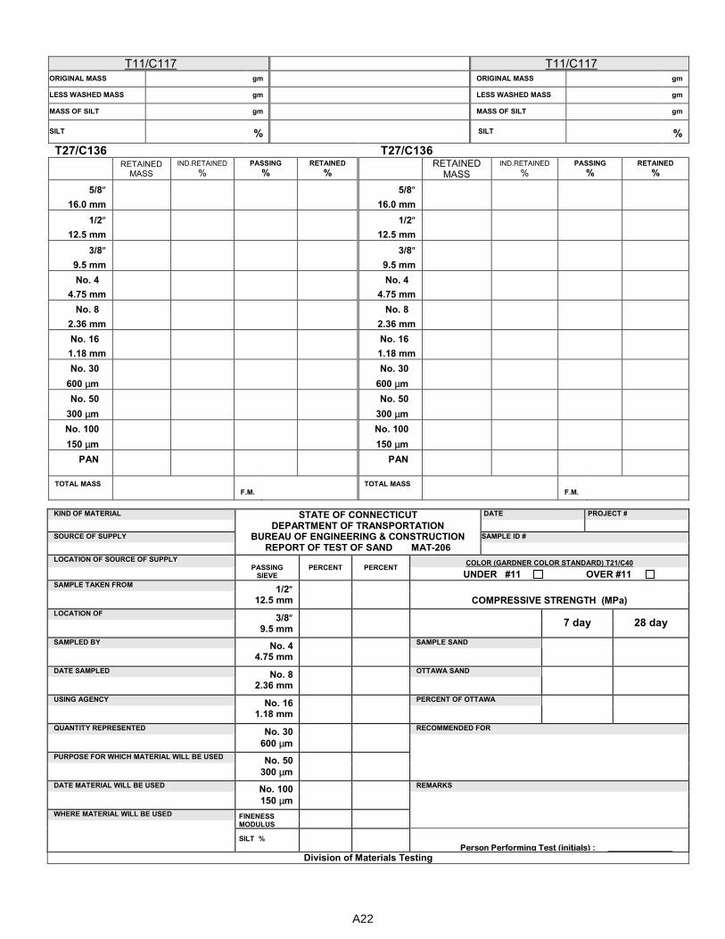
T11/C117 T11/C117 ORIGINAL MASS gm ORIGINAL MASS gm
LESS WASHED MASS gm LESS WASHED MASS gm
MASS OF SILT gm MASS OF SILT gm
SILT % SILT %
T27/C136 T27/C136 RETAINED
MASS
IND.RETAINED %
PASSING
% RETAINED
% RETAINED
MASS
IND.RETAINED %
PASSING
% RETAINED
%
5/8″ 16.0 mm
5/8″
16.0 mm
1/2″ 12.5 mm
1/2″
12.5 mm
3/8″ 9.5 mm
3/8″
9.5 mm
No. 4
4.75 mm
No. 4
4.75 mm
No. 8
2.36 mm
No. 8
2.36 mm
No. 16
1.18 mm
No. 16
1.18 mm
No. 30
600 µm
No. 30
600 µm
No. 50
300 µm
No. 50
300 µm
No. 100
150 µm
No. 100
150 µm
PAN
PAN
TOTAL MASS
F.M.
TOTAL MASS
F.M.
KIND OF MATERIAL STATE OF CONNECTICUT DEPARTMENT OF TRANSPORTATION
BUREAU OF ENGINEERING & CONSTRUCTION REPORT OF TEST OF SAND MAT-206
DATE
PROJECT #
SOURCE OF SUPPLY SAMPLE ID #
LOCATION OF SOURCE OF SUPPLY PASSING
SIEVE PERCENT PERCENT COLOR (GARDNER COLOR STANDARD) T21/C40
UNDER #11 OVER #11 SAMPLE TAKEN FROM
1/2″ 12.5 mm
COMPRESSIVE STRENGTH (MPa)
LOCATION OF 3/8″
9.5 mm 7 day 28 day
SAMPLED BY No. 4
4.75 mm
SAMPLE SAND
DATE SAMPLED No. 8
2.36 mm
OTTAWA SAND
USING AGENCY No. 16
1.18 mm
PERCENT OF OTTAWA
QUANTITY REPRESENTED No. 30
600 µm
RECOMMENDED FOR
PURPOSE FOR WHICH MATERIAL WILL BE USED No. 50
300 µm
DATE MATERIAL WILL BE USED No. 100
150 µm
REMARKS
WHERE MATERIAL WILL BE USED FINENESS MODULUS
SILT %
Person Performing Test (initials) :
Division of Materials Testing
A22

T27/C136 Non-cumulative RETAINED MASSES
NO. 3 NO. 6 NO. 8
2 1/2″ 63 mm
2″ 50 mm
1″
25 mm
1/2″ 12.5 mm
1 1/2″ 37.5 mm
3/4″
19 mm
3/8″ 9.5 mm
1 1/4″ 31.5 mm
1/2″
12.5 mm
No. 4 4.75 mm
1″ 25 mm
3/8″
9.5 mm
No. 8 2.36 mm
1/2″ 12.5 mm
No. 4
4.75 mm
No. 16 1.18 mm
PAN
PAN
PAN
KIND OF MATERIAL MAT-207
DEPARTMENT OF TRANSPORTATION
DATE PROJECT #
SOURCE OF SUPPLY DIVISION OF MATERIALS TESTING
REPORT OF TEST OF COARSE AGGREGATE
SAMPLE ID #
LOCATION OF SOURCE OF SUPPLY SQUARE MESH PERCENT PASSING PERCENTAGE OF WEAR
SIEVES SAMPLE TAKEN FROM
2 1/2″ 63 mm
SOUNDNESS % LOSS
LOCATION OF 2″ 50 mm
SAMPLED BY 1 1/2″ 37.5 mm
RECOMMENDED FOR
DATE SAMPLED 1 1/4″ 31.5 mm
USING AGENCY 1″ 25 mm
QUANTITY REPRESENTED 3/4″ 19 mm
PURPOSE FOR WHICH MATERIAL WILL BE USED 1/2″ 12.5 mm
REMARKS
3/8″ 9.5 mm
DATE MATERIAL WILL BE USED No. 4 4.75 mm
WHERE MATERIAL WILL BE USED No. 8 2.36 mm
No. 16
1.18 mm
Person Performing Test (initials): SAMPLE RECEIVED
No. 100
150 µm
Division of Materials Testing
NO. 4 NO. 67
2″ 50 mm
1 1/2″ 37.5 mm
1″
25 mm
1 1/4″ 31.5 mm
3/4″
19 mm
1″ 25 mm
1/2″
12.5 mm
3/4″ 19 mm
3/8″
9.5 mm
1/2″ 12.5 mm
No. 4
4.75 mm
3/8″ 9.5 mm
No. 8
2.36 mm
PAN
PAN
PAN
A23
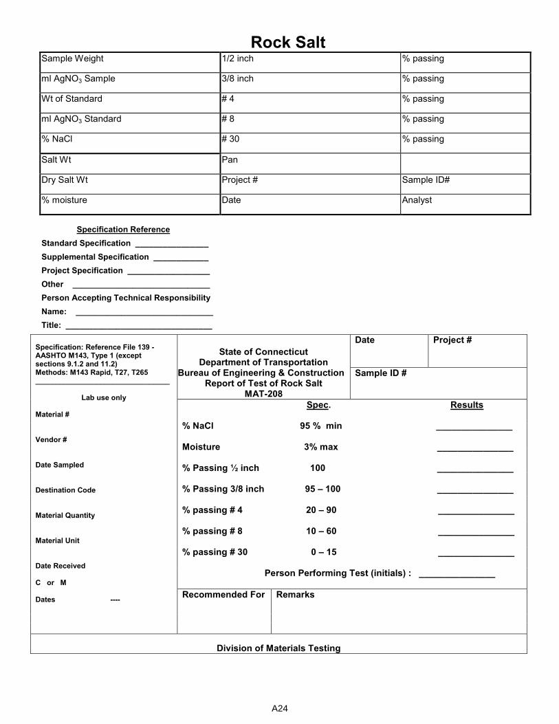
Rock Salt Sample Weight 1/2 inch % passing
ml AgNO3 Sample 3/8 inch % passing
Wt of Standard # 4 % passing
ml AgNO3 Standard # 8 % passing
% NaCl # 30 % passing
Salt Wt Pan
Dry Salt Wt Project # Sample ID#
% moisture Date Analyst
Specification Reference
Standard Specification ________________
Supplemental Specification ____________
Project Specification __________________
Other ______________________________
Person Accepting Technical Responsibility
Name: ______________________________
Title: ________________________________
Specification: Reference File 139 - AASHTO M143, Type 1 (except sections 9.1.2 and 11.2) Methods: M143 Rapid, T27, T265 _________________________________
Lab use only
Material # Vendor # Date Sampled Destination Code Material Quantity Material Unit Date Received C or M Dates ----
State of Connecticut Department of Transportation
Bureau of Engineering & Construction Report of Test of Rock Salt
MAT-208
Date Project #
Sample ID #
Spec. Results
% NaCl 95 % min _______________
Moisture 3% max _______________
% Passing ½ inch 100 _______________
% Passing 3/8 inch 95 – 100 _______________
% passing # 4 20 – 90 _______________
% passing # 8 10 – 60 _______________
% passing # 30 0 – 15 _______________
Person Performing Test (initials) : _______________
Recommended For
Remarks
Division of Materials Testing
A24

Calcium Chloride Project # Sample ID #
Date Analyst
Sample Wt.
N KmnO4
ml KmnO4
CaCl Factor
% CaCl
Specification Reference
Standard Specification ________________
Supplemental Specification ____________
Project Specification __________________
Other ______________________________
Person Accepting Technical Responsibility
Name: ______________________________
Title: _______________________________
Specification: AASHTO M144 via Form 815 Section (9.42.02) Methods: AASHTO T143, ASTM E449 _________________________________
Lab use only Material # Vendor # Date Sampled Destination Code Material Quantity Material Unit Date Received Batch # C or M Dates ----
State of Connecticut Department of Transportation
Bureau of Engineering & Construction Report of Test of Calcium Chloride
MAT-209
Date Project #
Sample ID #
Grade % CaCl Grade 1 min. 77% Grade 2 min. 90% % CaCl _____________________ Grade 3 min. 94%
Person Performing Test (initials) :__________________
Recommended For Remarks
Division of Materials Testing
A25

T96/C131 Los Angeles Abrasion Test
Pass. Ret.
(inches/mm) (inches/mm) Class A: 1 ½ (37.5) 1 (25) - + 12 (1.7mm) 1 (25) ¾ (19) - ¾ (19) ½ (12.5) - + 12 (1.7mm)
½ (12.5) 3/8 (9.5) - Total of +12 (1.7mm)
Total Weight = Total Wt. - Minus +12 (1.7mm)
Total of –12 (1.7mm) Class B: ¾ (19) ½ (12.5) - ½ (12.5) 3/8 (9.5) - Total Weight =
Total of -12 (1.7)mm) = = %
Total Weight
A: 1250 each required size – 12 spheres B: 1250 each required size – 11 spheres Dust =
KIND OF MATERIAL
State of Connecticut Department of Transportation
Bureau of Engineering & Construction Report of Test of L. A. Abrasion
& Soundness MAT-211
Date IN-HOUSE
TEST
SOURCE OF SUPPLY
Sample ID # LOCATION OF SOURCE OF SUPPLY
SAMPLE TAKEN FROM
(If Soundness reported, attach worksheet.)
Material #
Vendor #
Class:
Wear, %: %
Soundness, % Loss (if applicable):
%
LOCATION OF
SAMPLED BY
DATE SAMPLED
USING AGENCY
QUANTITY PRESENTED
PURPOSE FOR WHICH MATERIAL WILL BE USED
SAMPLE RECEIVED
DATE MATERIAL WILL BE USED Recommended For Remarks
WHERE MATERIAL WILL BE USED
A26
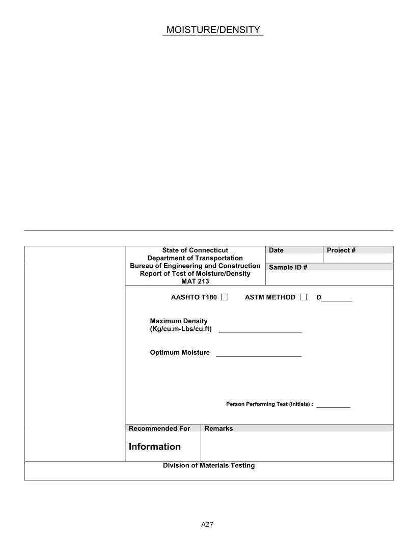
MOISTURE/DENSITY
State of Connecticut Department of Transportation
Bureau of Engineering and Construction Report of Test of Moisture/Density
MAT 213
Date Project #
Sample ID #
AASHTO T180 ASTM METHOD D
Maximum Density (Kg/cu.m-Lbs/cu.ft)
Optimum Moisture
Person Performing Test (initials) :
Recommended For Remarks
Information
Division of Materials Testing
A27

Connecticut Department of Transportation
Moisture Density Data Computation Sheet
MAT-217 - 6" Mold
Date Tested 1 2 3 4
Project No. Soil & Tare
Sampled From Tare
Sampled By Wet Weight
Date Sampled X X X X
Type of Material Volume 13.33 13.33 13.33 13.33
Tested By Wet Density
W.C.
Sample ID No. Dry Density
% Stone Replaced lbs. Wet 500 500 500 500
Maximum Density = pcf kg/m3 Dry
Optimum Moisture = % W.C.
Clear Sheet
A28

Connecticut Department of Transportation
Moisture Density Data Computation Sheet
MAT-218 - 4" Mold
Date Tested 1 2 3 4
Project No. Soil & Tare
Sampled From Tare
Sampled By Wet Weight
Date Sampled X X X X
Type of Material Volume 30 30 30 30
Tested By Wet Density
W.C.
Sample ID No. Dry Density
% Stone Replaced lbs. Wet 500 500 500 500
Maximum Density = pcf kg/m3 Dry
Optimum Moisture = % W.C.
Clear Sheet
A29

SPECIFIC GRAVITY AND ABSORPTION OF COARSE AGGREGATE – T 85/C127
DIVISION OF MATERIALS TESTING - MAT-219
Source: _____________________ Location: ___________________
Tested By: __________________ Date: ______________________
SAMPLE # 1 2 3
Mass of SSD Sample + Basket in Air
Less Mass of Basket in Air
Mass of SSD Sample B
Mass of Saturated Sample in Water + Basket in Water
Less Mass of Basket in Water
Mass of Saturated Sample in Water C
Mass of SSD Sample B
Less Mass of Saturated Sample in Water C
Loss in Mass (Volume of SSD Sample) B - C
Mass of Oven-Dry Sample + Pan
Less Mass of Pan
Mass of Oven-Dry Sample in Air A
Mass of SSD Sample in Air B
Less Mass of Oven-Dry Sample A
Mass of Water (Volume of Permeable Voids) B - A
Mass of Oven-Dry Sample A
Less Mass of Saturated Sample in Water C
Loss in Mass (Volume of Oven-Dry Sample) A - C
Bulk Specific Gravity A
B - C
Bulk Specific Gravity (SSD Basis) B
B - C
Apparent Specific Gravity A
A - C
Absorption % B - A
A x 100
A30

Connecticut Department of Transportation - Division of Materials Testing Fine Aggregate Soundness Worksheet T104/C88 - MAT-220
Kind of Material: Source: Tech/Eng. Initials:
Date Sampled: Location: Date Completed:
Original Grading (Plus #4) Sample Sizes For Original Grading Soak – Dry Schedule
Sieve In(mm)
Retained Mass
Pass & Ret. %
% Pass
Note:
Date in Sol. Time Date in oven
100
1/2 (12.5)
3/8 (9.5) Grading of Original Sample
#4 (4.75) Pass Ret. On
#8 (2.36) 3/8 (9.5) #4 (4.75) %
#16 (1.18) #4 (4.75) #8 (2.36) %
#30 (600 µ) #8 (2.36) #16 (1.18) %
#50 (300 µ) #16 (1.18) #30 (600 µ) %
Totals 100 #30 (600 µ) #50 (300 µ) %
Total 100 (Required Sample Not Less Than 100g For Each Size)
Passing Retained Actual Mass Mass Before Test Grams.
Mass After Test Grams.
Loss in Grams
Loss in %
Grading of Orig. Sample
Weighted Average %
3/8 (9.5) #4 (4.75)
#4 (4.75) #8 (2.36)
#8 (2.36) #16 (1.18)
#16 (1.18) #30 (600 µ)
#30 (600 µ) #50 (300 µ)
A31

Connecticut Department of Transportation - Division of Materials Testing Coarse Aggregate Soundness Worksheet T104/C88 - MAT-221
Kind of Material: Source: Tech/Eng. Initials:
Date Sampled: Location: Date Completed:
Original Grading (Plus #4) Sample Sizes For Original Grading Soak – Dry Schedule
Sieve In(mm)
Retained Mass
Pass & Ret. %
% Pass
# lbs. (kg)
Date in Sol. Date Date in oven
100 # lbs. (kg)
2 ½ (63) # lbs. (kg)
2 (50)
# lbs. (kg)
1 ½ (37.5)
Total lbs. (kg)
1 (25)
Grading of Original Sample
3/4 (19) Pass Ret. On
1/2 (12.5) 2 ½ (63) 1 ½ (37.5) %
3/8 (9.5) 1 ½
(37.5) 3/4 (19) %
# 4 (4.75) 3/4 (19) 3/8 (9.5) %
Totals 100 3/8 (9.5) # 4 (4.75) %
Total 100
Sieve Size
Not Less Than
Consisting of
Actual Mass
Mass Before Test Grams.
Mass After Test Grams.
Loss in Grams
Loss in %
Grading of Orig. Sample
Weighted Average %
2 ½ to 1 ½ (63) (37.5)
5000
3000 2 (50)
2000 1½ (37.5)
1 ½ to ¾ (37.5) (19)
1500
1000 1 (25)
500 ¾ (19)
¾ to 3/8 (19) (9.5)
1000 670 ½ (12.5)
330 3/8 (9.5)
3/8 to # 4 (9.5) (4.75)
300 300 # 4 (4.75)
A32

CONNECTICUT DEPARTMENT OF TRANSPORTATION DIVISION OF MATERIALS TESTING
ASSURANCE REPORT: FIELD TESTING PERSONNEL AND EQUIPMENT
MAT-222
Project Number: Date:
Location:
Inspected By: Consultant State
Name of Inspector(s) Certification(s) (NETTCP, ACI, Etc.) and Certification #s
Required Testing Equipment Air Meter Thermometer
Slump Cone Small Tools (scoops, measures, etc.) Tamping Rod (24” ok for all) Sampling Receptacle Strike Off Bar (⅛ x ¾ x 12) Cylinder Curing Box (operating to manufacturer specs) Mallet (1.25 ± .5 lbs)
Air Meter Calibration Date:
Remarks/Observations
Form Completed By District lab
A33
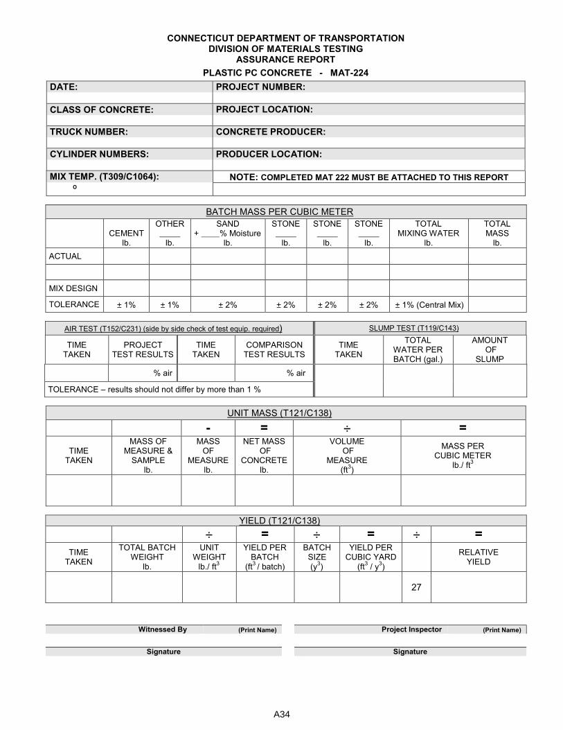
CONNECTICUT DEPARTMENT OF TRANSPORTATION DIVISION OF MATERIALS TESTING
ASSURANCE REPORT
PLASTIC PC CONCRETE - MAT-224
DATE: PROJECT NUMBER:
CLASS OF CONCRETE: PROJECT LOCATION:
TRUCK NUMBER: CONCRETE PRODUCER:
CYLINDER NUMBERS: PRODUCER LOCATION:
MIX TEMP. (T309/C1064): NOTE: COMPLETED MAT 222 MUST BE ATTACHED TO THIS REPORT
º
BATCH MASS PER CUBIC METER
CEMENT
lb.
OTHER
lb.
SAND + % Moisture
lb.
STONE
lb.
STONE
lb.
STONE
lb.
TOTAL MIXING WATER
lb.
TOTAL MASS
lb.
ACTUAL
MIX DESIGN
TOLERANCE ± 1% ± 1% ± 2% ± 2% ± 2% ± 2% ± 1% (Central Mix)
AIR TEST (T152/C231) (side by side check of test equip. required) SLUMP TEST (T119/C143)
TIME TAKEN
PROJECT TEST RESULTS
TIME TAKEN
COMPARISON TEST RESULTS
TIME TAKEN
TOTAL WATER PER BATCH (gal.)
AMOUNT OF
SLUMP
% air % air
TOLERANCE – results should not differ by more than 1 %
UNIT MASS (T121/C138)
- = ÷ =
TIME TAKEN
MASS OF MEASURE &
SAMPLE lb.
MASS OF
MEASURE lb.
NET MASS OF
CONCRETE lb.
VOLUME OF
MEASURE (ft
3)
MASS PER CUBIC METER
lb./ ft3
YIELD (T121/C138)
÷ = ÷ = ÷ =
TIME TAKEN
TOTAL BATCH WEIGHT
lb.
UNIT WEIGHT
lb./ ft3
YIELD PER BATCH
(ft3
/ batch)
BATCH SIZE (y
3)
YIELD PER CUBIC YARD
(ft3 / y
3)
RELATIVE
YIELD
27
Witnessed By (Print Name) Project Inspector (Print Name)
Signature Signature
A34
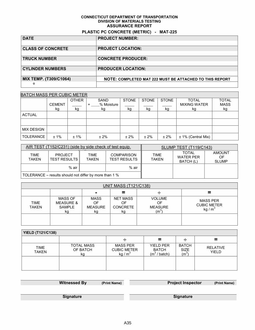
CONNECTICUT DEPARTMENT OF TRANSPORTATION DIVISION OF MATERIALS TESTING
ASSURANCE REPORT
PLASTIC PC CONCRETE (METRIC) - MAT-225
DATE PROJECT NUMBER:
CLASS OF CONCRETE PROJECT LOCATION:
TRUCK NUMBER CONCRETE PRODUCER:
CYLINDER NUMBERS PRODUCER LOCATION:
MIX TEMP. (T309/C1064) NOTE: COMPLETED MAT 222 MUST BE ATTACHED TO THIS REPORT
º
BATCH MASS PER CUBIC METER
CEMENT
kg
OTHER
kg
SAND + % Moisture
kg
STONE
kg
STONE
kg
STONE
kg
TOTAL MIXING WATER
kg
TOTAL MASS
kg
ACTUAL
MIX DESIGN
TOLERANCE ± 1% ± 1% ± 2% ± 2% ± 2% ± 2% ± 1% (Central Mix)
AIR TEST (T152/C231) (side by side check of test equip. required)
SLUMP TEST (T119/C143)
TIME TAKEN
PROJECT TEST RESULTS
TIME TAKEN
COMPARISON TEST RESULTS
TIME TAKEN
TOTAL WATER PER BATCH (L)
AMOUNT OF
SLUMP
% air % air
TOLERANCE – results should not differ by more than 1 %
UNIT MASS (T121/C138)
- = ÷ =
TIME TAKEN
MASS OF MEASURE &
SAMPLE kg
MASS OF
MEASURE kg
NET MASS OF
CONCRETE kg
VOLUME OF
MEASURE (m
3)
MASS PER CUBIC METER
kg / m3
YIELD (T121/C138)
÷ = ÷ =
TIME TAKEN
TOTAL MASS OF BATCH
kg
MASS PER CUBIC METER
kg / m3
YIELD PER BATCH
(m3 / batch)
BATCH SIZE (m
3)
RELATIVE YIELD
Witnessed By (Print Name) Project Inspector (Print Name)
Signature Signature
A35
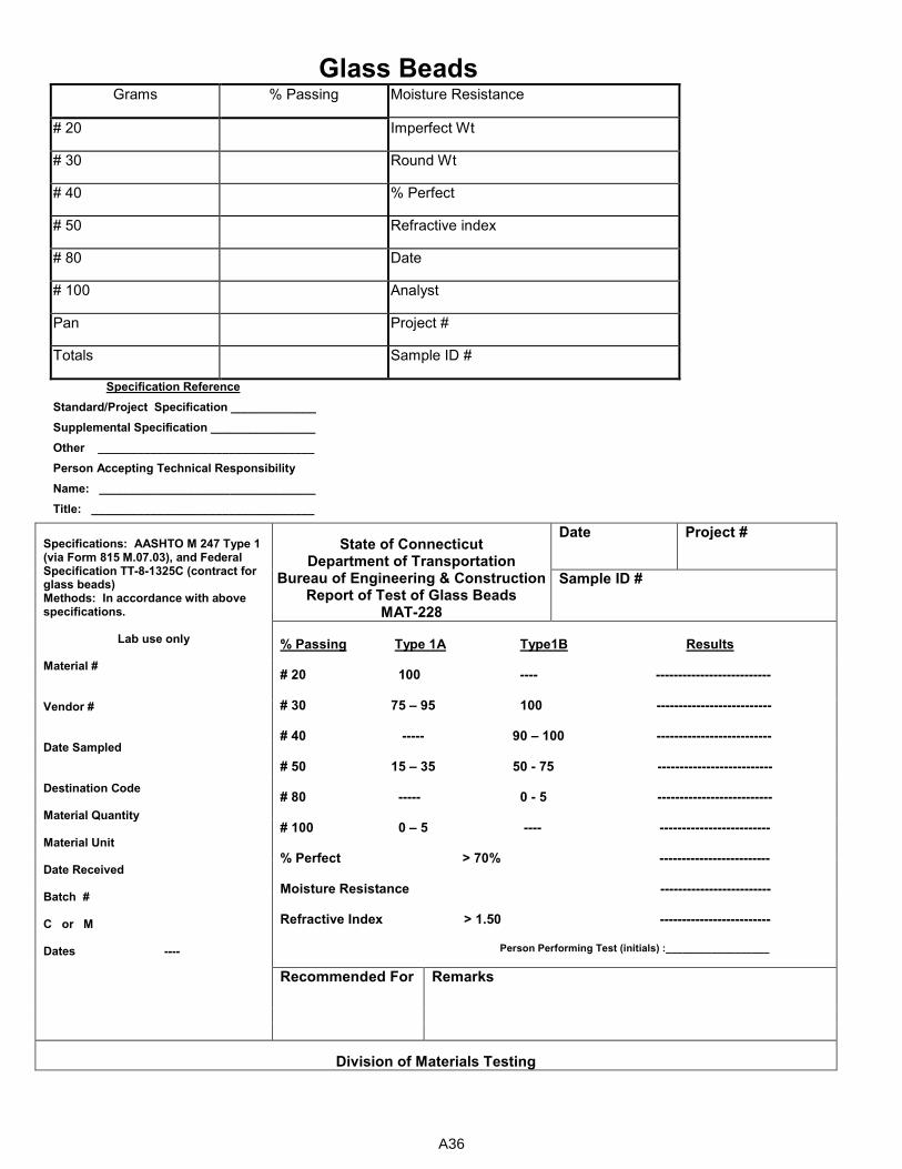
Glass Beads Grams % Passing Moisture Resistance
# 20 Imperfect Wt
# 30 Round Wt
# 40 % Perfect
# 50 Refractive index
# 80 Date
# 100 Analyst
Pan Project #
Totals Sample ID #
Specification Reference
Standard/Project Specification _____________
Supplemental Specification ________________
Other _________________________________
Person Accepting Technical Responsibility
Name: _________________________________
Title: __________________________________
Specifications: AASHTO M 247 Type 1 (via Form 815 M.07.03), and Federal Specification TT-8-1325C (contract for glass beads) Methods: In accordance with above specifications.
Lab use only
Material # Vendor # Date Sampled Destination Code Material Quantity Material Unit Date Received Batch # C or M Dates ----
State of Connecticut Department of Transportation
Bureau of Engineering & Construction Report of Test of Glass Beads
MAT-228
Date Project #
Sample ID #
% Passing Type 1A Type1B Results # 20 100 ---- -------------------------- # 30 75 – 95 100 -------------------------- # 40 ----- 90 – 100 -------------------------- # 50 15 – 35 50 - 75 -------------------------- # 80 ----- 0 - 5 -------------------------- # 100 0 – 5 ---- ------------------------- % Perfect > 70% ------------------------- Moisture Resistance ------------------------- Refractive Index > 1.50 -------------------------
Person Performing Test (initials) :__________________
Recommended For Remarks
Division of Materials Testing
A36
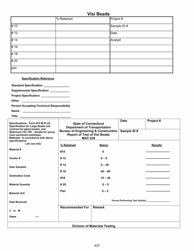
Visi Beads % Retained Project #
# 10 Sample ID #
# 12 Date
# 14 Analyst
# 16
# 18
# 20
pan
Specification Reference
Standard Specification ________________
Supplemental Specification ____________
Project Specification __________________
Other ______________________________
Person Accepting Technical Responsibility
Name: ______________________________
Title: ________________________________
Specifications: Form 815 M.07.22, Specification for Large Beads (via contract for glass beads), and Reference File 199 – (beads for epoxy resin pavement markings). Methods: In accordance with above specifications.
Lab use only Material # Vendor # Date Sampled Destination Code Material Quantity Material Unit Date Received C or M Dates ----
State of Connecticut Department of Transportation
Bureau of Engineering & Construction Report of Test of Visi Beads
MAT-229
Date Project #
Sample ID #
% Retained Specs. Results #10 0 ------------------------- # 12 0 – 5 ------------------------- # 14 5 – 20 ------------------------- # 16 40 – 80 ------------------------- #18 10 – 40 ------------------------- # 20 0 – 5 ------------------------- Pan 0 – 2 -------------------------
Person Performing Test (initials) :__________________
Recommended For Remark
Division of Materials Testing
A37

Water Appearance Color
pH Water Factor
ml Silver Nitrate Chlorides
Project # Sample ID #
Date Analyst
Specification Reference
Standard Specification ________________ Supplemental Specification ____________ Project Specification __________________ Other ______________________________ Person Accepting Technical Responsibility Name: ______________________________ Title: ________________________________ ___________________________________________________________________________________________
Specification: Form 815 M.03.01-4 Methods: In accordance with AASHTO T26
Note: If tests indicate unfavorable results, further testing may be required. (T107, T131, or T154 and T106, or other recommended tests in cooperation with Concrete/Steel Section)
State of Connecticut Department of Transportation
Bureau of Engineering & Construction Report of Test of Water
MAT-230
Date Project #
Sample ID #
Appearance _____________ Color _______________
pH (T26, range 4.5 – 8.5) _____________
Chloride Ion Concentration (D512) _____________
Person Performing Test (initials) :__________________
Recommended For
Remarks
Division of Materials Testing
A38
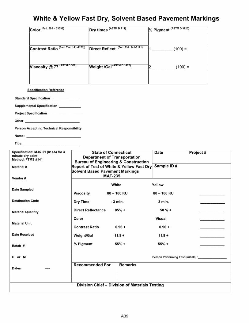
White & Yellow Fast Dry, Solvent Based Pavement Markings
Color (Fed. 595 – 33538)
Dry times (ASTM D 711)
% Pigment (ASTM D 3720)
Contrast Ratio (Fed. Test 141-4121))
Direct Reflect. (Fed. Ref. 141-6121)
1 _________ (100) =
Viscosity @ 77 (ASTM D 562)
Weight /Gal (ASTM D 1475)
2 __________ (100) =
Specification Reference
Standard Specification ________________ Supplemental Specification ____________ Project Specification __________________ Other ______________________________ Person Accepting Technical Responsibility Name: ______________________________ Title: _______________________________
Specification: M.07.21 (814A) for 3 minute dry paint Method: FTMS #141 Material # Vendor # Date Sampled Destination Code Material Quantity Material Unit Date Received Batch # C or M Dates ----
State of Connecticut Department of Transportation
Bureau of Engineering & Construction Report of Test of White & Yellow Fast Dry Solvent Based Pavement Markings
MAT-235
Date Project #
Sample ID #
White Yellow Viscosity 80 – 100 KU 80 – 100 KU ____________ Dry Time - 3 min. 3 min. ____________ Direct Reflectance 85% + 50 % + ____________ Color Visual ____________ Contrast Ratio 0.96 + 0.96 + ____________ Weight/Gal 11.8 + 11.8 + ____________ % Pigment 55% + 55% + ____________
Person Performing Test (initials) :__________________
Recommended For
Remarks
Division Chief – Division of Materials Testing
A39
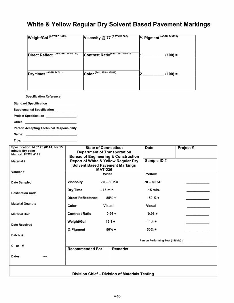
White & Yellow Regular Dry Solvent Based Pavement Markings
Weight/Gal
(ASTM D 1475) Viscosity @ 77
(ASTM D 562) % Pigment
(ASTM D 3720)
Direct Reflect. (Fed. Ref. 141-6121)
Contrast Ratio(Fed.Test 141-4121)
1 __________ (100) =
Dry times (ASTM D 711)
Color (Fed. 595 – 33538)
2 __________ (100) =
Specification Reference Standard Specification ________________
Supplemental Specification ____________
Project Specification __________________
Other ______________________________
Person Accepting Technical Responsibility
Name: ______________________________
Title: ________________________________
Specification: M.07.20 (814A) for 15 minute dry paint Method: FTMS #141 Material # Vendor # Date Sampled Destination Code Material Quantity Material Unit Date Received Batch # C or M Dates ----
State of Connecticut Department of Transportation
Bureau of Engineering & Construction Report of White & Yellow Regular Dry
Solvent Based Pavement Markings MAT-236
Date Project #
Sample ID #
White Yellow Viscosity 70 – 80 KU 70 – 80 KU ____________ Dry Time - 15 min. 15 min. ____________ Direct Reflectance 85% + 50 % + ____________ Color Visual Visual ____________ Contrast Ratio 0.96 + 0.96 + ____________ Weight/Gal 12.8 + 11.4 + ____________ % Pigment 50% + 50% + ____________
Person Performing Test (initials) :__________________
Recommended For
Remarks
Division Chief – Division of Materials Testing
A40
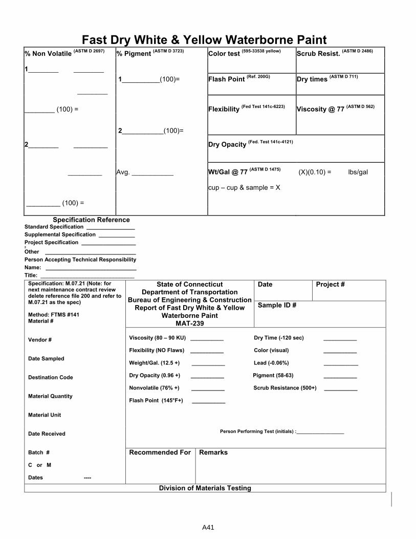
Fast Dry White & Yellow Waterborne Paint % Non Volatile
(ASTM D 2697) % Pigment
(ASTM D 3723) Color test
(595-33538 yellow) Scrub Resist.
(ASTM D 2486)
1________ ________
1__________(100)= Flash Point (Ref. 200G)
Dry times (ASTM D 711)
________
________ (100) = Flexibility (Fed Test 141c-6223)
Viscosity @ 77 (ASTM D 562)
2___________(100)=
2________ _________ Dry Opacity (Fed. Test 141c-4121)
_________ Avg. ___________ Wt/Gal @ 77 (ASTM D 1475)
(X)(0.10) = lbs/gal
cup – cup & sample = X
_________ (100) =
Specification Reference
Standard Specification ________________
Supplemental Specification ____________
Project Specification __________________ 2
Other ______________________________
Person Accepting Technical Responsibility
Name: ______________________________
Title: _______________________________
Specification: M.07.21 (Note: for next maintenance contract review delete reference file 200 and refer to M.07.21 as the spec) Method: FTMS #141 Material # Vendor # Date Sampled Destination Code Material Quantity Material Unit Date Received Batch # C or M Dates ----
State of Connecticut Department of Transportation
Bureau of Engineering & Construction Report of Fast Dry White & Yellow
Waterborne Paint MAT-239
Date Project #
Sample ID #
Viscosity (80 – 90 KU) ___________ Dry Time (-120 sec) ___________ Flexibility (NO Flaws) ___________ Color (visual) ___________ Weight/Gal. (12.5 +) ___________ Lead (-0.06%) _____________ Dry Opacity (0.96 +) ___________ Pigment (58-63) ___________ Nonvolatile (76% +) ___________ Scrub Resistance (500+) ___________ Flash Point (145°F+) ___________ Person Performing Test (initials) :__________________
Recommended For Remarks
Division of Materials Testing
A41
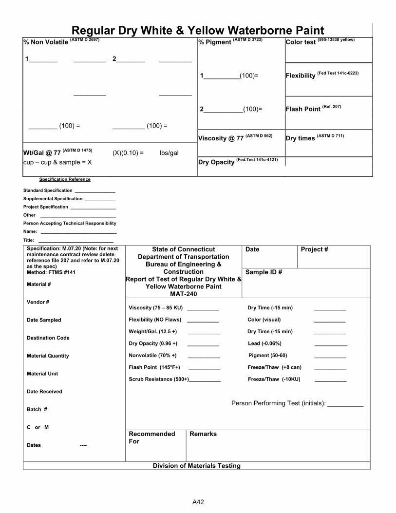
Regular Dry White & Yellow Waterborne Paint % Non Volatile
(ASTM D 2697) % Pigment
(ASTM D 3723) Color test
(595-13538 yellow)
1________ _________ 2________ _________
1__________(100)= Flexibility (Fed Test 141c-6223)
_________ _________
2___________(100)= Flash Point (Ref. 207)
________ (100) = _________ (100) =
Viscosity @ 77 (ASTM D 562)
Dry times (ASTM D 711)
Wt/Gal @ 77 (ASTM D 1475)
(X)(0.10) = lbs/gal
cup – cup & sample = X Dry Opacity (Fed.Test 141c-4121)
Specification Reference
Standard Specification ________________
Supplemental Specification ____________
Project Specification __________________
Other ______________________________
Person Accepting Technical Responsibility
Name: ______________________________
Title: __________________________
Specification: M.07.20 (Note: for next maintenance contract review delete reference file 207 and refer to M.07.20 as the spec) Method: FTMS #141 Material # Vendor # Date Sampled Destination Code Material Quantity Material Unit Date Received Batch # C or M Dates ----
State of Connecticut Department of Transportation
Bureau of Engineering & Construction
Report of Test of Regular Dry White & Yellow Waterborne Paint
MAT-240
Date Project #
Sample ID #
Viscosity (75 – 85 KU) ___________ Dry Time (-15 min) ___________ Flexibility (NO Flaws) ___________ Color (visual) ___________ Weight/Gal. (12.5 +) ___________ Dry Time (-15 min) ___________ Dry Opacity (0.96 +) ___________ Lead (-0.06%) _____________ Nonvolatile (70% +) ___________ Pigment (50-60) ___________ Flash Point (145°F+) ___________ Freeze/Thaw (+8 can) ___________ Scrub Resistance (500+)___________ Freeze/Thaw (-10KU) ___________
Person Performing Test (initials): __________
Recommended For
Remarks
Division of Materials Testing
A42
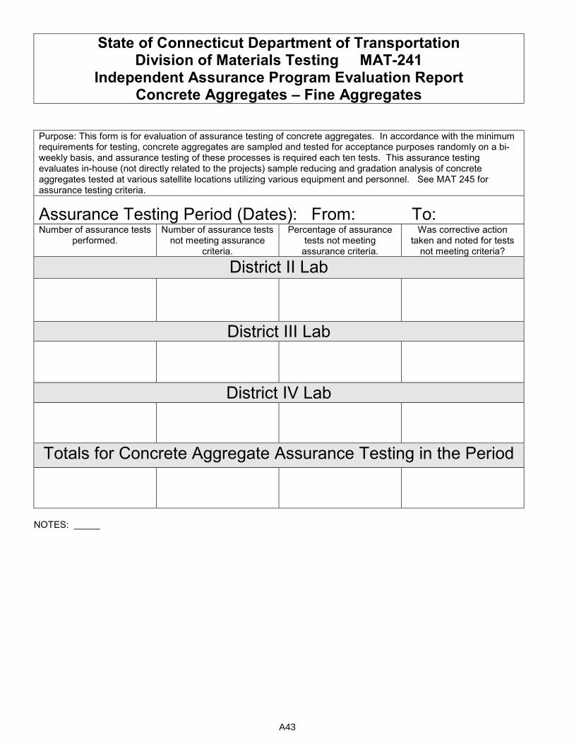
State of Connecticut Department of Transportation Division of Materials Testing MAT-241
Independent Assurance Program Evaluation Report Concrete Aggregates – Fine Aggregates
Purpose: This form is for evaluation of assurance testing of concrete aggregates. In accordance with the minimum requirements for testing, concrete aggregates are sampled and tested for acceptance purposes randomly on a bi-weekly basis, and assurance testing of these processes is required each ten tests. This assurance testing evaluates in-house (not directly related to the projects) sample reducing and gradation analysis of concrete aggregates tested at various satellite locations utilizing various equipment and personnel. See MAT 245 for assurance testing criteria.
Assurance Testing Period (Dates): From: To: Number of assurance tests
performed. Number of assurance tests
not meeting assurance criteria.
Percentage of assurance tests not meeting assurance criteria.
Was corrective action taken and noted for tests
not meeting criteria?
District II Lab
District III Lab
District IV Lab
Totals for Concrete Aggregate Assurance Testing in the Period
NOTES:
A43
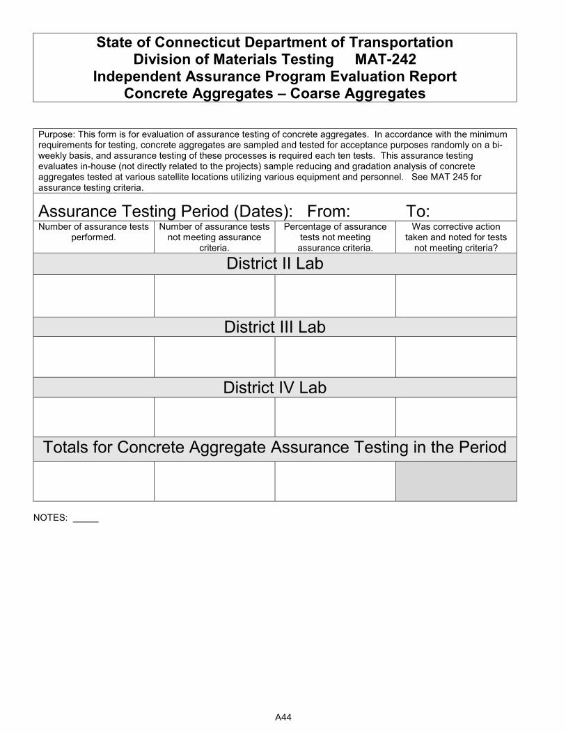
State of Connecticut Department of Transportation Division of Materials Testing MAT-242
Independent Assurance Program Evaluation Report Concrete Aggregates – Coarse Aggregates
Purpose: This form is for evaluation of assurance testing of concrete aggregates. In accordance with the minimum requirements for testing, concrete aggregates are sampled and tested for acceptance purposes randomly on a bi-weekly basis, and assurance testing of these processes is required each ten tests. This assurance testing evaluates in-house (not directly related to the projects) sample reducing and gradation analysis of concrete aggregates tested at various satellite locations utilizing various equipment and personnel. See MAT 245 for assurance testing criteria.
Assurance Testing Period (Dates): From: To: Number of assurance tests
performed. Number of assurance tests
not meeting assurance criteria.
Percentage of assurance tests not meeting assurance criteria.
Was corrective action taken and noted for tests
not meeting criteria?
District II Lab
District III Lab
District IV Lab
Totals for Concrete Aggregate Assurance Testing in the Period
NOTES:
A44
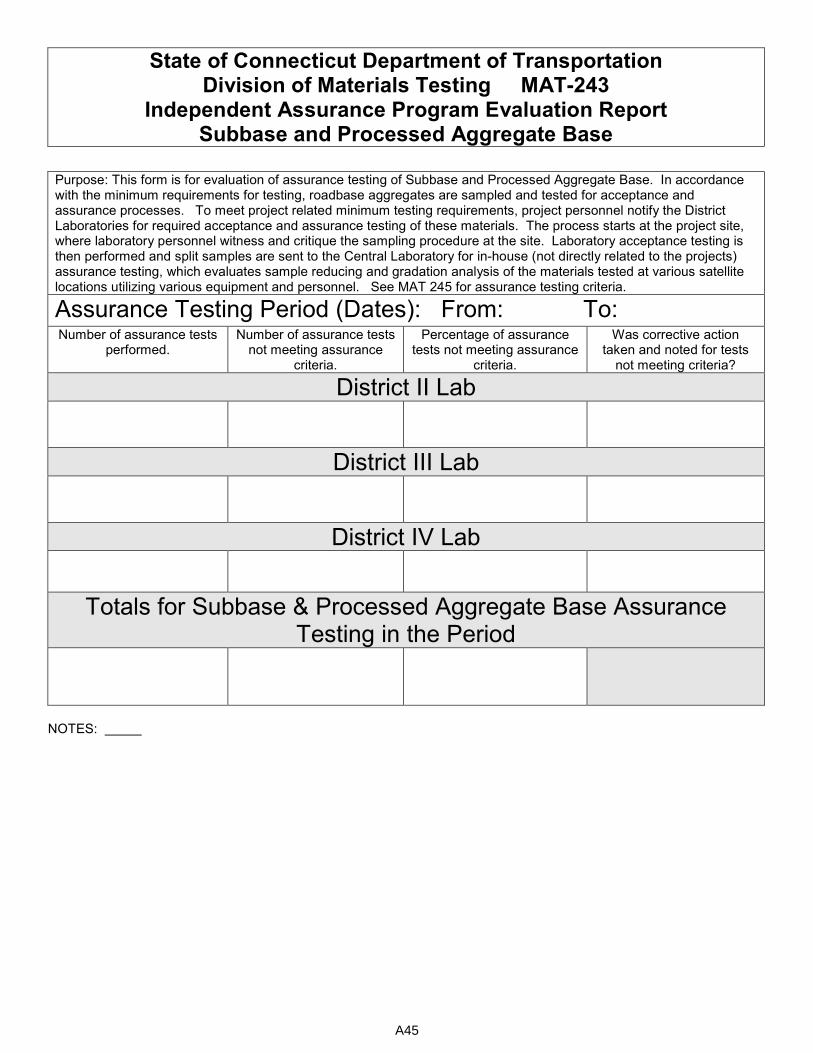
State of Connecticut Department of Transportation Division of Materials Testing MAT-243
Independent Assurance Program Evaluation Report Subbase and Processed Aggregate Base
Purpose: This form is for evaluation of assurance testing of Subbase and Processed Aggregate Base. In accordance with the minimum requirements for testing, roadbase aggregates are sampled and tested for acceptance and assurance processes. To meet project related minimum testing requirements, project personnel notify the District Laboratories for required acceptance and assurance testing of these materials. The process starts at the project site, where laboratory personnel witness and critique the sampling procedure at the site. Laboratory acceptance testing is then performed and split samples are sent to the Central Laboratory for in-house (not directly related to the projects) assurance testing, which evaluates sample reducing and gradation analysis of the materials tested at various satellite locations utilizing various equipment and personnel. See MAT 245 for assurance testing criteria.
Assurance Testing Period (Dates): From: To:
Number of assurance tests performed.
Number of assurance tests not meeting assurance
criteria.
Percentage of assurance tests not meeting assurance
criteria.
Was corrective action taken and noted for tests
not meeting criteria?
District II Lab
District III Lab
District IV Lab
Totals for Subbase & Processed Aggregate Base Assurance Testing in the Period
NOTES:
A45
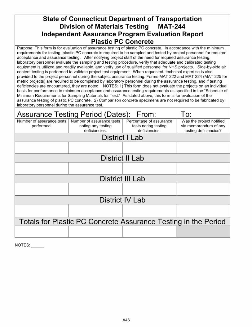
State of Connecticut Department of Transportation Division of Materials Testing MAT-244
Independent Assurance Program Evaluation Report Plastic PC Concrete
Purpose: This form is for evaluation of assurance testing of plastic PC concrete. In accordance with the minimum requirements for testing, plastic PC concrete is required to be sampled and tested by project personnel for required acceptance and assurance testing. After notifying project staff of the need for required assurance testing, laboratory personnel evaluate the sampling and testing procedure, verify that adequate and calibrated testing equipment is utilized and readily available, and verify use of qualified personnel for NHS projects. Side-by-side air content testing is performed to validate project test equipment. When requested, technical expertise is also provided to the project personnel during the subject assurance testing. Forms MAT 222 and MAT 224 (MAT 225 for metric projects) are required to be completed by laboratory personnel during the assurance testing, and if testing deficiencies are encountered, they are noted. NOTES: 1) This form does not evaluate the projects on an individual basis for conformance to minimum acceptance and assurance testing requirements as specified in the “Schedule of Minimum Requirements for Sampling Materials for Test.” As stated above, this form is for evaluation of the assurance testing of plastic PC concrete. 2) Comparison concrete specimens are not required to be fabricated by laboratory personnel during the assurance test.
Assurance Testing Period (Dates): From: To:
Number of assurance tests performed.
Number of assurance tests noting any testing
deficiencies.
Percentage of assurance tests noting testing
deficiencies.
Was the project notified via memorandum of any
testing deficiencies?
District I Lab
District II Lab
District III Lab
District IV Lab
Totals for Plastic PC Concrete Assurance Testing in the Period
NOTES:
A46
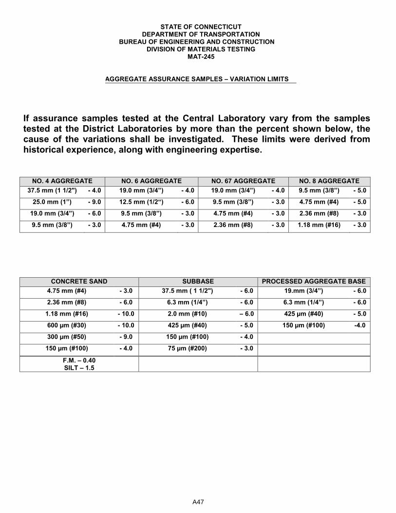
STATE OF CONNECTICUT DEPARTMENT OF TRANSPORTATION
BUREAU OF ENGINEERING AND CONSTRUCTION DIVISION OF MATERIALS TESTING
MAT-245
AGGREGATE ASSURANCE SAMPLES – VARIATION LIMITS
If assurance samples tested at the Central Laboratory vary from the samples tested at the District Laboratories by more than the percent shown below, the cause of the variations shall be investigated. These limits were derived from historical experience, along with engineering expertise.
NO. 4 AGGREGATE NO. 6 AGGREGATE NO. 67 AGGREGATE NO. 8 AGGREGATE
37.5 mm (1 1/2") - 4.0 19.0 mm (3/4”) - 4.0 19.0 mm (3/4”) - 4.0 9.5 mm (3/8”) - 5.0
25.0 mm (1”) - 9.0 12.5 mm (1/2“) - 6.0 9.5 mm (3/8”) - 3.0 4.75 mm (#4) - 5.0
19.0 mm (3/4”) - 6.0 9.5 mm (3/8”) - 3.0 4.75 mm (#4) - 3.0 2.36 mm (#8) - 3.0
9.5 mm (3/8”) - 3.0 4.75 mm (#4) - 3.0 2.36 mm (#8) - 3.0 1.18 mm (#16) - 3.0
CONCRETE SAND SUBBASE PROCESSED AGGREGATE BASE
4.75 mm (#4) - 3.0 37.5 mm ( 1 1/2") - 6.0 19.mm (3/4”) - 6.0
2.36 mm (#8) - 6.0 6.3 mm (1/4”) - 6.0 6.3 mm (1/4”) - 6.0
1.18 mm (#16) - 10.0 2.0 mm (#10) – 6.0 425 µm (#40) - 5.0
600 µm (#30) - 10.0 425 µm (#40) - 5.0 150 µm (#100) -4.0
300 µm (#50) - 9.0 150 µm (#100) - 4.0
150 µm (#100) - 4.0 75 µm (#200) - 3.0
F.M. – 0.40 SILT – 1.5
A47
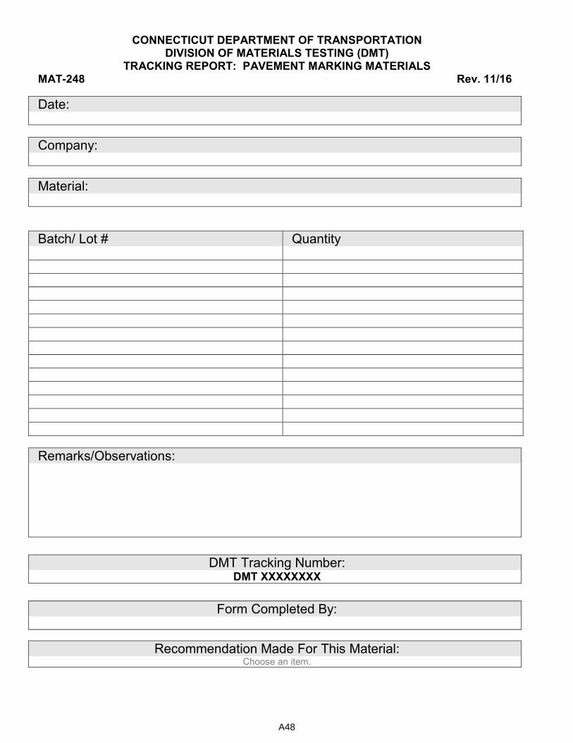
CONNECTICUT DEPARTMENT OF TRANSPORTATION DIVISION OF MATERIALS TESTING (DMT)
TRACKING REPORT: PAVEMENT MARKING MATERIALS MAT-248 Rev. 11/16
Date:
Company:
Material:
Batch/ Lot # Quantity
Remarks/Observations:
DMT Tracking Number:
DMT XXXXXXXX
Form Completed By:
Recommendation Made For This Material: Choose an item.
A48
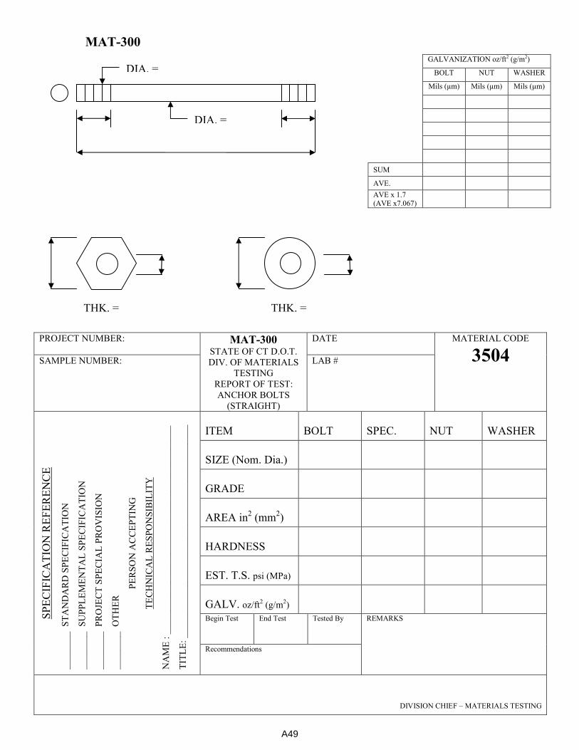
MAT-300
PROJECT NUMBER: MAT-300
STATE OF CT D.O.T.
DIV. OF MATERIALS
TESTING
REPORT OF TEST:
ANCHOR BOLTS
(STRAIGHT)
DATE MATERIAL CODE
3504 SAMPLE NUMBER: LAB #
SP
EC
IFIC
AT
ION
RE
FE
RE
NC
E
__
___
___
S
TA
ND
AR
D S
PE
CIF
ICA
TIO
N
__
___
___
S
UP
PL
EM
EN
TA
L S
PE
CIF
ICA
TIO
N
__
___
___
P
RO
JEC
T S
PE
CIA
L P
RO
VIS
ION
__
___
___
O
TH
ER
PE
RS
ON
AC
CE
PT
ING
TE
CH
NIC
AL
RE
SP
ON
SIB
ILIT
Y
NA
ME
: _
__
___
___
___
___
___
__
__
___
___
___
___
___
___
__
__
TIT
LE
: _
__
___
___
___
___
___
__
__
___
___
___
___
___
___
__
__
_
ITEM BOLT SPEC. NUT WASHER
SIZE (Nom. Dia.)
GRADE
AREA in2 (mm
2)
HARDNESS
EST. T.S. psi (MPa)
GALV. oz/ft2 (g/m
2)
Begin Test End Test Tested By REMARKS
Recommendations
DIVISION CHIEF – MATERIALS TESTING
GALVANIZATION oz/ft2 (g/m2)
BOLT NUT WASHER
Mils (µm) Mils (µm) Mils (µm)
SUM
AVE.
AVE x 1.7 (AVE x7.067)
DIA. =
DIA. =
THK. = THK. =
A49

MAT-301
PROJECT NUMBER: MAT-301
STATE OF CT D.O.T.
DIV. OF MAT. TESTING
REPORT OF TEST:
ANCHOR BOLTS
(WITH HOOK)
DATE MATERIAL CODE
3504 SAMPLE NUMBER: LAB #
SP
EC
IFIC
AT
ION
RE
FE
RE
NC
E
__
___
___
S
TA
ND
AR
D S
PE
CIF
ICA
TIO
N
__
___
___
S
UP
PL
EM
EN
TA
L S
PE
CIF
ICA
TIO
N
__
___
___
P
RO
JEC
T S
PE
CIA
L P
RO
VIS
ION
__
___
___
O
TH
ER
PE
RS
ON
AC
CE
PT
ING
TE
CH
NIC
AL
RE
SP
ON
SIB
ILIT
Y
NA
ME
: _
__
___
___
___
___
___
__
__
___
___
___
___
___
___
__
__
TIT
LE
: _
__
___
___
___
___
___
__
__
___
___
___
___
___
___
__
__
_
ITEM BOLT SPEC. NUT WASHER
SIZE (Nom. Dia.)
GRADE
AREA in2 (mm
2)
HARDNESS
EST. T.S. PSI (MPa)
GALV. Oz/ft2(g/m
2)
RECOMMENDED FOR REMARKS
c:\jwh\forms\Anchor Bolt with Hook combo.doc
DIVISION CHIEF – MATERIALS TESTING
GALV.
DIA. =
DIA. =
GALVANIZATION oz/ft2 (g/m2)
BOLT NUT WASHER
Mils (µm) Mils (µm) Mils (µm)
SUM
AVE.
AVE x 1.7
(AVE x7.067)
THK. = THK. =
A50

MAT-302
PROJECT NUMBER: MAT-302
STATE OF CT D.O.T.
DIV. OF MATERIALS
TESTING
REPORT OF TEST:
HEX BOLTS
DATE MATERIAL CODE
SAMPLE NUMBER: LAB #
SP
EC
IFIC
AT
ION
RE
FE
RE
NC
E
__
___
___
S
TA
ND
AR
D S
PE
CIF
ICA
TIO
N
__
___
___
S
UP
PL
EM
EN
TA
L S
PE
CIF
ICA
TIO
N
__
___
___
P
RO
JEC
T S
PE
CIA
L P
RO
VIS
ION
__
___
___
O
TH
ER
PE
RS
ON
AC
CE
PT
ING
TE
CH
NIC
AL
RE
SP
ON
SIB
ILIT
Y
NA
ME
: _
__
___
___
___
___
___
__
__
___
___
___
___
___
___
__
__
TIT
LE
: _
__
___
___
___
___
___
__
__
___
___
___
___
___
___
__
__
_
ITEM BOLT SPEC. NUT WASHER
SIZE (Nom. Dia.)
GRADE
AREA (mm2)
HARDNESS
EST. T.S. (MPa)
GALV. (g/m2)
Begin Date End Date Tested
By
REMARKS
DIVISION CHIEF – MATERIALS TESTING
GALV.
DIA. =
DIA. =
GALVANIZATION oz/ft2 (g/m2)
BOLT NUT WASHER
Mils (µm) Mils (µm) Mils (µm)
SUM
AVE.
AVE x 1.7
(AVE x7.067)
THK. = THK. =
A51
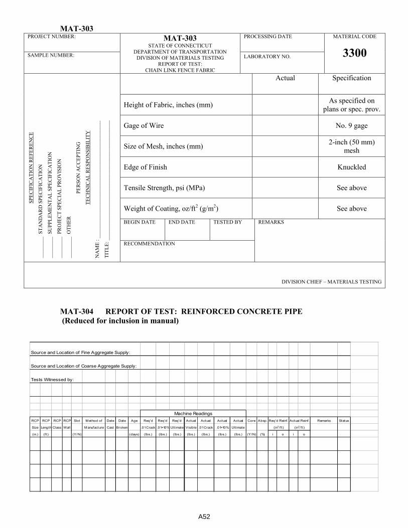
MAT-303 PROJECT NUMBER: MAT-303
STATE OF CONNECTICUT
DEPARTMENT OF TRANSPORTATION DIVISION OF MATERIALS TESTING
REPORT OF TEST:
CHAIN LINK FENCE FABRIC
PROCESSING DATE
MATERIAL CODE
3300 SAMPLE NUMBER: LABORATORY NO.
SP
EC
IFIC
AT
ION
RE
FE
RE
NC
E
____
___
_
ST
AN
DA
RD
SP
EC
IFIC
AT
ION
____
___
_
SU
PP
LE
ME
NT
AL
SP
EC
IFIC
AT
ION
____
___
_
PR
OJE
CT
SP
EC
IAL
PR
OV
ISIO
N
____
___
_
OT
HE
R
PE
RS
ON
AC
CE
PT
ING
TE
CH
NIC
AL
RE
SP
ON
SIB
ILIT
Y
NA
ME
: _
__
___
___
___
___
___
___
___
___
___
___
___
___
___
__
TIT
LE
: ___
___
___
___
___
___
___
____
___
___
___
___
___
___
__
Actual Specification
Height of Fabric, inches (mm) As specified on
plans or spec. prov.
Gage of Wire
No. 9 gage
Size of Mesh, inches (mm) 2-inch (50 mm)
mesh
Edge of Finish
Knuckled
Tensile Strength, psi (MPa)
See above
Weight of Coating, oz/ft2 (g/m
2)
See above
BEGIN DATE END DATE TESTED BY REMARKS
RECOMMENDATION
DIVISION CHIEF – MATERIALS TESTING
MAT-304 REPORT OF TEST: REINFORCED CONCRETE PIPE
(Reduced for inclusion in manual)
Source and Location of Fine Aggregate Supply:
Source and Location of Coarse Aggregate Supply:
Tests Witnessed by:
RCP RCP RCP RCP Slot M ethod of Date Date Age Req'd Req'd Req'd Actual Actual Actual Actual Core Absp. Remarks Status
Size Length Class Wall M anufacture Cast Broken .01 Crack .01+10% Ult imate Visible .01 Crack .01+10% Ult imate
(in.) (f t) (Y/N) (days) (lbs.) (lbs.) (lbs.) (lbs.) (lbs.) (lbs.) (lbs.) (Y/N) (%) i o i o
(in2/ f t )
Actual Reinf.
(in2/ f t )
Machine Readings
Req'd Reinf.
A52
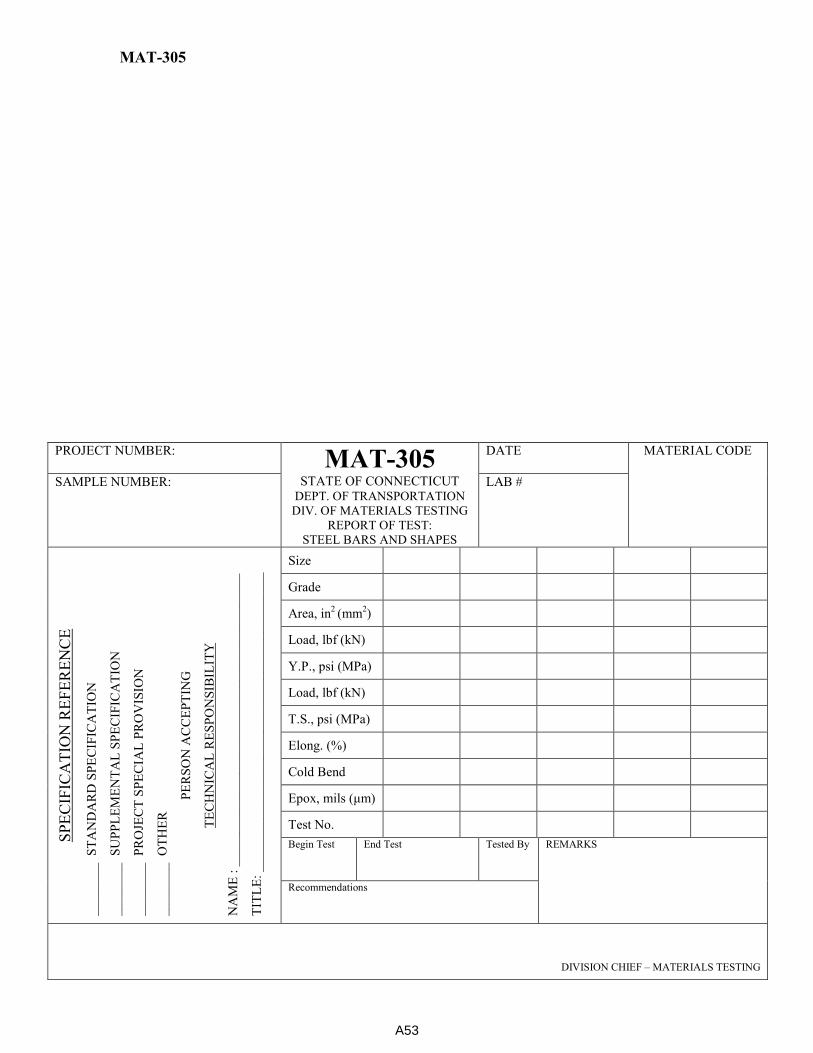
MAT-305
PROJECT NUMBER:
MAT-305 STATE OF CONNECTICUT
DEPT. OF TRANSPORTATION
DIV. OF MATERIALS TESTING
REPORT OF TEST:
STEEL BARS AND SHAPES
DATE MATERIAL CODE
SAMPLE NUMBER: LAB #
SP
EC
IFIC
AT
ION
RE
FE
RE
NC
E
__
___
___
S
TA
ND
AR
D S
PE
CIF
ICA
TIO
N
__
___
___
S
UP
PL
EM
EN
TA
L S
PE
CIF
ICA
TIO
N
__
___
___
P
RO
JEC
T S
PE
CIA
L P
RO
VIS
ION
__
___
___
O
TH
ER
PE
RS
ON
AC
CE
PT
ING
TE
CH
NIC
AL
RE
SP
ON
SIB
ILIT
Y
NA
ME
: _
__
___
___
___
___
___
__
__
___
___
___
___
___
___
__
__
TIT
LE
: _
__
___
___
___
___
___
__
__
___
___
___
___
___
___
__
__
_
Size
Grade
Area, in2 (mm
2)
Load, lbf (kN)
Y.P., psi (MPa)
Load, lbf (kN)
T.S., psi (MPa)
Elong. (%)
Cold Bend
Epox, mils (µm)
Test No. Begin Test End Test Tested By REMARKS
Recommendations
DIVISION CHIEF – MATERIALS TESTING
A53

MAT-306
Tables From ASTM A 82
Steel Wire, Plain, For Concrete Reinforcement
Table 1 Tension Test Requirements
Tensile strength, min, ksi (MPa) 80 (550)
Yield strength, min, ksi (MPa) 70 (485)
Reduction of area, min, % 30A AFor material testing of 100 ksi (690 MPa) tensile strength, the reduction of area shall be not less than 25%.
Table 2 Tension Test Requirements (Material for Welded Wire Reinforcement)
Size W1.2
and Larger
Smaller than Size W1.2
Tensile strength based on wire nom. area, min, ksi (MPa) 75 (515) 70 (485)
Yield strength based on wire nom. Area, min, ksi (MPa) 65 (450) 56 (385)
Reduction of area, min, % 30A 30A AFor material testing over 100 ksi (690 MPa) tensile strength, the reduction of area shall be not less than
25 %.
Table 4 Permissible Variation in Wire Diameter
Size Number Nominal Diameter,
in. (mm)
Permissible Variation Plus and Minus, in.
(mm)
Smaller than W5 Under 0.252 (6.40) 0.003 (0.08)
W5 to W12, incl 0.252 (6.40) to 0.391 (9.93), incl 0.004 (0.10)
Over to W20, incl Over 0.391 (9.93) to
0.505 (12.83), incl 0.006 (0.15)
Over W20 Over 0.505 (12.83) 0.008 (0.20)
PROJECT NUMBER: MAT-306 STATE OF CONNECTICUT
DEPARTMENT OF TRANSPORTATION
DIVISION OF MATERIALS TESTING REPORT OF TEST:
PLAIN WIRE FOR WELDED WIRE FABRIC
PROCESSING DATE
MATERIAL CODE
3145 SAMPLE NUMBER: LABORATORY NO.
SP
EC
IFIC
AT
ION
RE
FE
RE
NC
E
____
___
_
ST
AN
DA
RD
SP
EC
IFIC
AT
ION
____
___
_
SU
PP
LE
ME
NT
AL
SP
EC
IFIC
AT
ION
____
___
_
PR
OJE
CT
SP
EC
IAL
PR
OV
ISIO
N
____
___
_
OT
HE
R
PE
RS
ON
AC
CE
PT
ING
TE
CH
NIC
AL
RE
SP
ON
SIB
ILIT
Y
NA
ME
: _
__
___
___
___
___
___
___
___
___
___
___
___
___
___
__
TIT
LE
: ___
___
___
___
___
___
___
____
___
___
___
___
___
___
__
Horizontal Horizontal
Spec. Vertical
Vertical
Spec.
Spacing (in.)
___
___
Size Number
Act. Diam. (in)
Nom. Area (in2)
___
___
Load (lbf)
___
___
T.S. (psi)
Condition
___
___
BEGIN DATE END DATE TESTED BY REMARKS
RECOMMENDATION
DIVISION CHIEF – MATERIALS TESTING
A54
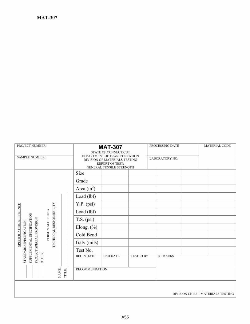
MAT-307
PROJECT NUMBER: MAT-307 STATE OF CONNECTICUT
DEPARTMENT OF TRANSPORTATION DIVISION OF MATERIALS TESTING
REPORT OF TEST:
GENERAL TENSILE STRENGTH
PROCESSING DATE
MATERIAL CODE
SAMPLE NUMBER: LABORATORY NO.
SP
EC
IFIC
AT
ION
RE
FE
RE
NC
E
____
___
_
ST
AN
DA
RD
SP
EC
IFIC
AT
ION
____
___
_
SU
PP
LE
ME
NT
AL
SP
EC
IFIC
AT
ION
____
___
_
PR
OJE
CT
SP
EC
IAL
PR
OV
ISIO
N
____
___
_
OT
HE
R
PE
RS
ON
AC
CE
PT
ING
TE
CH
NIC
AL
RE
SP
ON
SIB
ILIT
Y
NA
ME
: _
__
___
___
___
___
___
___
___
___
___
___
___
___
___
__
TIT
LE
: ___
___
___
___
___
___
___
____
___
___
___
___
___
___
__
Size
Grade
Area (in2)
Load (lbf)
Y.P. (psi)
Load (lbf)
T.S. (psi)
Elong. (%)
Cold Bend
Galv (mils)
Test No. BEGIN DATE END DATE TESTED BY REMARKS
RECOMMENDATION
DIVISION CHIEF – MATERIALS TESTING
A55
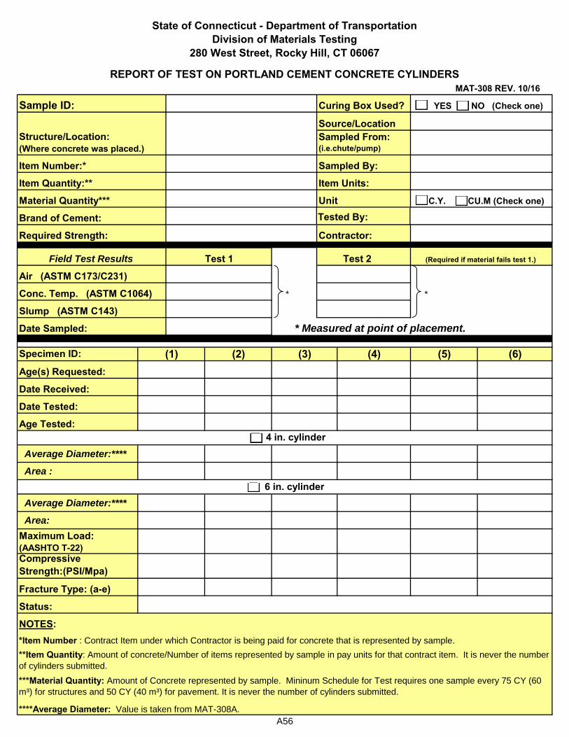
* *
Specimen ID: (2) (4) (5) (6)Age(s) Requested:
Date Received:
Date Tested:
Age Tested:
Average Diameter:****
Area :
Average Diameter:****
Area:
Maximum Load: (AASHTO T-22)Compressive Strength:(PSI/Mpa)
Fracture Type: (a-e)
Status:
Structure/Location: (Where concrete was placed.)
State of Connecticut - Department of TransportationDivision of Materials Testing
MAT-308 REV. 10/16
Sample ID:
280 West Street, Rocky Hill, CT 06067
Material Quantity***
Brand of Cement:
Item Number:*
Item Quantity:**
Required Strength:
(3)
Air (ASTM C173/C231)
Conc. Temp. (ASTM C1064)
Field Test Results
* Measured at point of placement.
Slump (ASTM C143)
(1)
Test 2Test 1
*Item Number : Contract Item under which Contractor is being paid for concrete that is represented by sample.
**Item Quantity: Amount of concrete/Number of items represented by sample in pay units for that contract item. It is never the number
of cylinders submitted.
Contractor:
4 in. cylinder
(Required if material fails test 1.)
NOTES:
****Average Diameter: Value is taken from MAT-308A.
Date Sampled:
6 in. cylinder
Item Units:
REPORT OF TEST ON PORTLAND CEMENT CONCRETE CYLINDERS
***Material Quantity: Amount of Concrete represented by sample. Mininum Schedule for Test requires one sample every 75 CY (60
m³) for structures and 50 CY (40 m³) for pavement. It is never the number of cylinders submitted.
Curing Box Used? YES NO (Check one)
Unit C.Y. CU.M (Check one)
Source/LocationSampled From: (i.e.chute/pump)
Sampled By:
Tested By:
A56
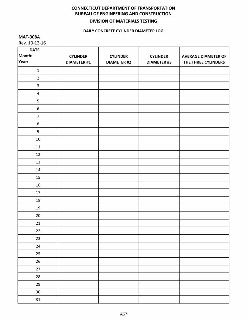
DATE
Month:
Year:
CYLINDER
DIAMETER #1
CYLINDER
DIAMETER #2
CYLINDER
DIAMETER #3
AVERAGE DIAMETER OF
THE THREE CYLINDERS
1
2
3
4
5
6
7
8
9
10
11
12
13
14
15
16
17
18
19
20
21
22
23
24
25
26
27
28
29
30
31
Rev. 10-12-16
CONNECTICUT DEPARTMENT OF TRANSPORTATION
DIVISION OF MATERIALS TESTING
DAILY CONCRETE CYLINDER DIAMETER LOG
BUREAU OF ENGINEERING AND CONSTRUCTION
MAT-308A
A57

MAT-309
Compression Units
Specimen: #1 #2 #3
Received Weight (WR), lb or kg
Gross Area (Ag), in2
or mm2
Max. Comp. Load (PMAX), lbf or N
Absorption Units
Specimen: #1 #2 #3
Ave. Height (H), in or mm
Immersed Weight (Wi), lb or kg
Saturated Weight (Ws), lb or kg
O.D. Weight – Final (Wd), lb or kg
Oven Dry Density (D), lb/ft3
= [Wd/(Ws-Wi)] x 62.4
Oven Dry Density (D), kg/m3 = [Wd/(Ws-Wi)] x 1000
Absorption, lb/ft3
= [(Ws-Wd)/(Ws-Wi)] x 62.4
Absorption, kg/m3 = [(Ws-Wd)/(Ws-Wi)] x 1000
Net Volume (Vn), ft3 or mm
3 = Wd/D
Average Net Area (An), in2 = (Vn x 1728)/H
Average Net Area (An), mm2 = Vn/H
PROJECT NUMBER:
MAT-309 STATE OF CONNECTICUT
DEPARTMENT OF TRANSPORTATION
DIVISION OF MATERIALS TESTING REPORT OF TEST:
MASONRY CONCRETE UNITS/BRICK
PROCESSING DATE
MATERIAL CODE
SAMPLE NUMBER: LABORATORY NO.
SP
EC
IFIC
AT
ION
RE
FE
RE
NC
E
____
___
_
ST
AN
DA
RD
SP
EC
IFIC
AT
ION
____
___
_
SU
PP
LE
ME
NT
AL
SP
EC
IFIC
AT
ION
____
___
_
PR
OJE
CT
SP
EC
IAL
PR
OV
ISIO
N
____
___
_
OT
HE
R
PE
RS
ON
AC
CE
PT
ING
TE
CH
NIC
AL
RE
SP
ON
SIB
ILIT
Y
NA
ME
: _
__
___
___
___
___
___
___
___
___
___
___
___
___
___
__
TIT
LE
: ___
___
___
___
___
___
___
____
___
___
___
___
___
___
__
#1 #2 #3 Ave. Spec.
Ave.
Spec.
Ind.
Height, in (mm)
Length, in (mm)
Width, in (mm)
Comp. Strength,
psi (MPa)
Absorption,
lb/ft3 (kg/m
3)
BEGIN DATE END DATE TESTED BY REMARKS
RECOMMENDATION
DIVISION CHIEF – MATERIALS TESTING
A58
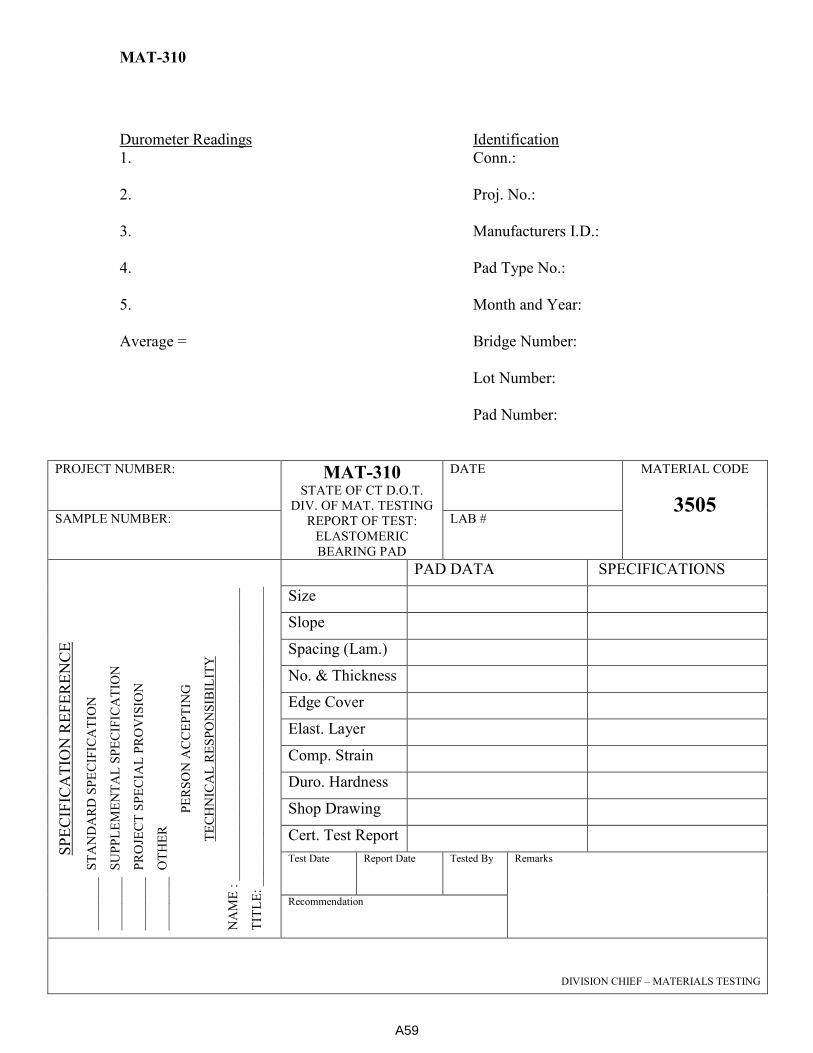
MAT-310
Durometer Readings Identification
1. Conn.:
2. Proj. No.:
3. Manufacturers I.D.:
4. Pad Type No.:
5. Month and Year:
Average = Bridge Number:
Lot Number:
Pad Number:
PROJECT NUMBER: MAT-310
STATE OF CT D.O.T.
DIV. OF MAT. TESTING
REPORT OF TEST:
ELASTOMERIC
BEARING PAD
DATE MATERIAL CODE
3505 SAMPLE NUMBER: LAB #
SP
EC
IFIC
AT
ION
RE
FE
RE
NC
E
__
___
___
S
TA
ND
AR
D S
PE
CIF
ICA
TIO
N
__
___
___
S
UP
PL
EM
EN
TA
L S
PE
CIF
ICA
TIO
N
__
___
___
P
RO
JEC
T S
PE
CIA
L P
RO
VIS
ION
__
___
___
O
TH
ER
PE
RS
ON
AC
CE
PT
ING
TE
CH
NIC
AL
RE
SP
ON
SIB
ILIT
Y
NA
ME
: _
__
___
___
___
___
___
__
__
___
___
___
___
___
___
__
__
TIT
LE
: _
__
___
___
___
___
___
__
__
___
___
___
___
___
___
__
__
_
PAD DATA SPECIFICATIONS
Size
Slope
Spacing (Lam.)
No. & Thickness
Edge Cover
Elast. Layer
Comp. Strain
Duro. Hardness
Shop Drawing
Cert. Test Report
Test Date Report Date Tested By Remarks
Recommendation
DIVISION CHIEF – MATERIALS TESTING
A59

MAT-311 (Deleted)
MAT-312
Compression Units
Specimen: #1 #2 #3 #4 #5
Gross Area (A), in2
(mm2)
Maximum Load (W), lbf (N)
Absorption Units
Specimen: #1 #2 #3 #4 #5
Saturated Weight 5-h boil(Wb),
lb (kg)
Oven Dry Weight – Final (Wd),
lb (kg)
Compressive Strength, psi = W/A
Absorption, % = 100(Wb-Wd)/Wd
PROJECT NUMBER:
MAT-312 STATE OF CONNECTICUT
DEPARTMENT OF TRANSPORTATION
DIVISION OF MATERIALS TESTING REPORT OF TEST:
CLAY BRICK
PROCESSING DATE
MATERIAL CODE
SAMPLE NUMBER: LABORATORY NO.
SP
EC
IFIC
AT
ION
RE
FE
RE
NC
E
____
___
_
ST
AN
DA
RD
SP
EC
IFIC
AT
ION
____
___
_
SU
PP
LE
ME
NT
AL
SP
EC
IFIC
AT
ION
____
___
_
PR
OJE
CT
SP
EC
IAL
PR
OV
ISIO
N
____
___
_
OT
HE
R
PE
RS
ON
AC
CE
PT
ING
TE
CH
NIC
AL
RE
SP
ON
SIB
ILIT
Y
NA
ME
: _
__
___
___
___
___
___
___
___
___
___
___
___
___
___
__
TIT
LE
: ___
___
___
___
___
___
___
____
___
___
___
___
___
___
__
#1 #2 #3 #4 #5 Ave Spec.
Ave.
Spec.
Ind.
Depth, in (mm)
Length, in (mm)
Width, in (mm)
Strength,
psi (MPa)
Absorption by 5-
hour boiling (%)
BEGIN DATE END DATE TESTED BY REMARKS
RECOMMENDATION
DIVISION CHIEF – MATERIALS TESTING
A60

MAT-313
PROJECT NUMBER: MAT-313 STATE OF CONNECTICUT
DEPARTMENT OF TRANSPORTATION
DIVISION OF MATERIALS TESTING REPORT OF TEST:
CONCRETE BLOCK FOR SLOPE PROTECTION
PROCESSING DATE
MATERIAL CODE
3197 SAMPLE NUMBER: LABORATORY NO.
SP
EC
IFIC
AT
ION
RE
FE
RE
NC
E
____
___
_
ST
AN
DA
RD
SP
EC
IFIC
AT
ION
____
___
_
SU
PP
LE
ME
NT
AL
SP
EC
IFIC
AT
ION
____
___
_
PR
OJE
CT
SP
EC
IAL
PR
OV
ISIO
N
____
___
_
OT
HE
R
PE
RS
ON
AC
CE
PT
ING
TE
CH
NIC
AL
RE
SP
ON
SIB
ILIT
Y
NA
ME
: _
__
___
___
___
___
___
___
___
___
___
___
___
___
___
__
TIT
LE
: ___
___
___
___
___
___
___
____
___
___
___
___
___
___
__
SAMPLE 1 SAMPLE 2 SAMPLE 3 SPEC.
L, Length,
inches (mm)
16 +/- ½ in
406 +/- 12.5 mm
W, Width,
inches (mm)
8 +/- ½
203 +/- 12.5 mm
H, Height,
inches (mm)
4 +/- ½
100 +/- 12.5 mm
A, Area,
in2 (mm
2)
----
Load,
lbf (N)
----
Stength,
psi (MPa)
3000 psi
21 MPa
BEGIN DATE END DATE TESTED BY REMARKS
RECOMMENDATION
DIVISION CHIEF – MATERIALS TESTING
8” (203 mm)
16” (406 mm)
4” (100 mm)
A61
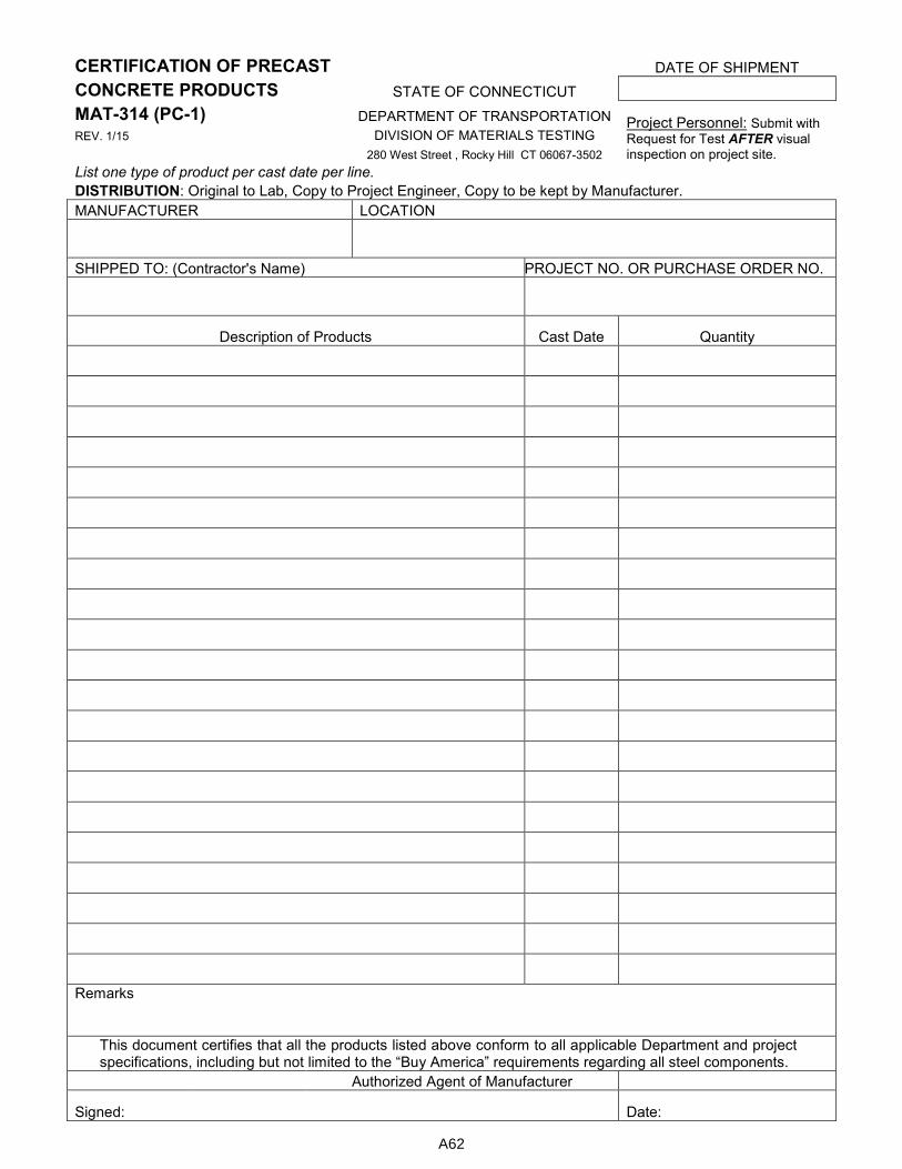
CERTIFICATION OF PRECAST DATE OF SHIPMENT
CONCRETE PRODUCTS STATE OF CONNECTICUT
MAT-314 (PC-1) DEPARTMENT OF TRANSPORTATION Project Personnel: Submit with
Request for Test AFTER visual inspection on project site.
REV. 1/15 DIVISION OF MATERIALS TESTING
280 West Street , Rocky Hill CT 06067-3502
List one type of product per cast date per line.
DISTRIBUTION: Original to Lab, Copy to Project Engineer, Copy to be kept by Manufacturer.
MANUFACTURER LOCATION
SHIPPED TO: (Contractor's Name) PROJECT NO. OR PURCHASE ORDER NO.
Description of Products Cast Date Quantity
Remarks
This document certifies that all the products listed above conform to all applicable Department and project specifications, including but not limited to the “Buy America” requirements regarding all steel components.
Authorized Agent of Manufacturer
Signed: Date:
A62
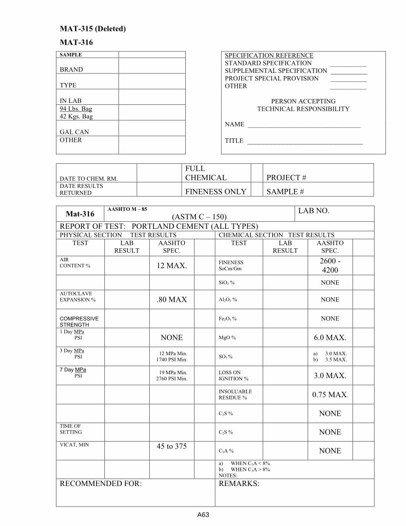
MAT-315 (Deleted)
MAT-316
SAMPLE SPECIFICATION REFERENCE
STANDARD SPECIFICATION ___________
SUPPLEMENTAL SPECIFICATION ___________
PROJECT SPECIAL PROVISION ___________
OTHER ___________
PERSON ACCEPTING
TECHNICAL RESPONSIBILITY
NAME __________________________________
TITLE _____________________________
BRAND
TYPE
IN LAB
94 Lbs. Bag
42 Kgs. Bag
GAL CAN
OTHER
DATE TO CHEM. RM.
FULL
CHEMICAL PROJECT # DATE RESULTS
RETURNED FINENESS ONLY SAMPLE #
Mat-316 AASHTO M – 85
(ASTM C – 150) LAB NO.
REPORT OF TEST: PORTLAND CEMENT (ALL TYPES) PHYSICAL SECTION TEST RESULTS CHEMICAL SECTION TEST RESULTS
TEST LAB
RESULT
AASHTO
SPEC.
TEST LAB
RESULT
AASHTO
SPEC.
AIR CONTENT %
12 MAX.
FINENESS SoCm/Gm
2600 -
4200
SiO2 % NONE
AUTOCLAVE
EXPANSION %
.80 MAX
Al2O3 %
NONE
COMPRESSIVE STRENGTH
Fe2O3 %
NONE
1 Day MPa
PSI
NONE
MgO %
6.0 MAX.
3 Day MPa
PSI
12 MPa Min. 1740 PSI Min.
SO3 %
a) 3.0 MAX. b) 3.5 MAX.
7 Day MPa PSI
19 MPa Min.
2760 PSI Min.
LOSS ON
IGNITION %
3.0 MAX.
INSOLUABLE RESIDUE %
0.75 MAX.
C3S %
NONE
TIME OF SETTING
C2S %
NONE
VICAT, MIN
45 to 375 C3A %
NONE
a) WHEN C3A < 8%
b) WHEN C3A > 8% NOTES:
RECOMMENDED FOR:
REMARKS:
A63

MAT-316 - Page 2
CEMENT TYPE ____ LAB NO.
T – 106
C – 109 DATE: TIME:
T – 137
C – 185
CUBES MADE:
AIR CONTENT
AGE
WATER %
DATE
WATER ml
1.
FLOW %
2.
GROSS WT
3.
- CUP WT
AVG
= NET WT
FACTOR
NET WT*
FACTOR
AIR CONT %
DATE
T-107
C-151 AUTOCLAVE
T-129
C-187 NORMAL CONSISTENCY
TIME
BARS MADE
WATER %
BARS MEASURE
WATER ml
SWITCHES ON
PENETRATION
mm
VENT CLOSED
295 PSI
T-131
C-191 VICAT – TIME OF SET
ADD 3 HOURS
MADE
INITIAL
SWITCHES OFF
TIME OF DAY
DOWN 1 ½ HRS
HR: MIN
COOL 30 MIN
MINUTES
AFTER STEAM
BEFORE STEAM
DIFFERENCE
% EXPANSION
A64
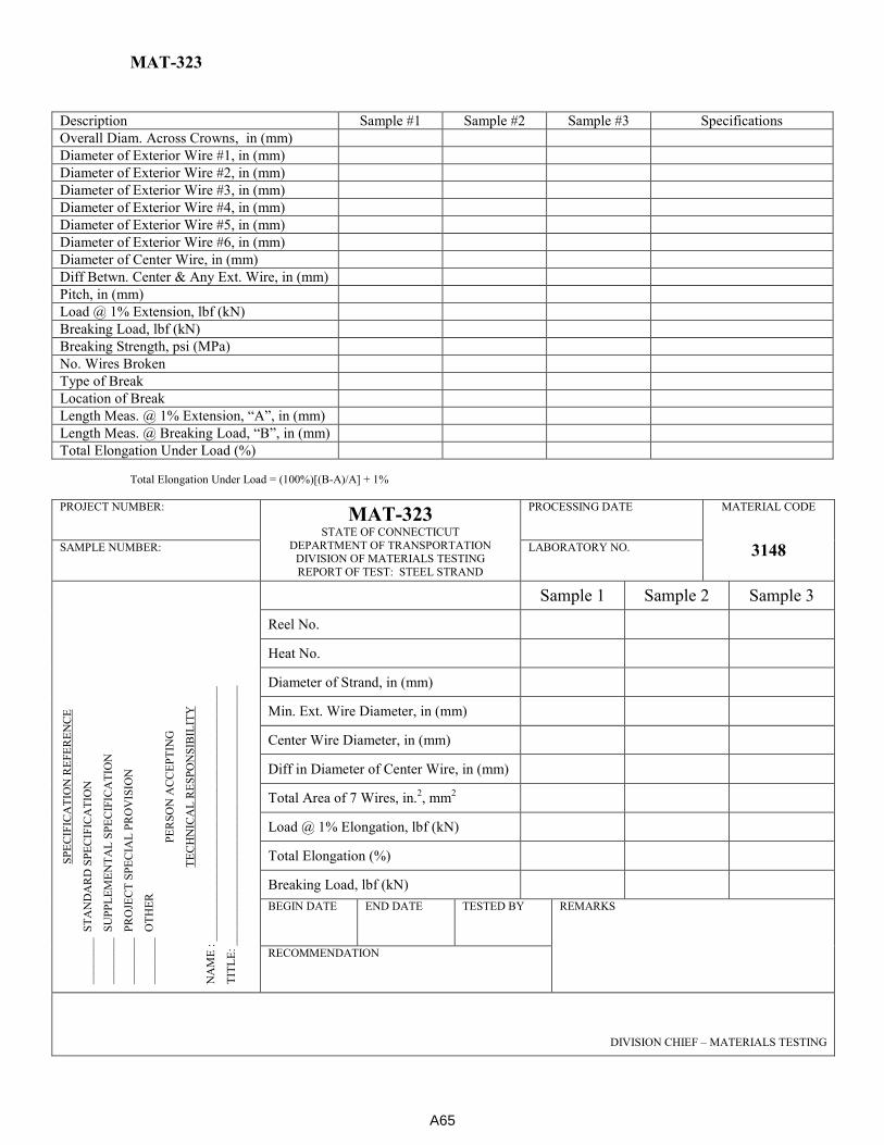
MAT-323
Description Sample #1 Sample #2 Sample #3 Specifications
Overall Diam. Across Crowns, in (mm)
Diameter of Exterior Wire #1, in (mm)
Diameter of Exterior Wire #2, in (mm)
Diameter of Exterior Wire #3, in (mm)
Diameter of Exterior Wire #4, in (mm)
Diameter of Exterior Wire #5, in (mm)
Diameter of Exterior Wire #6, in (mm)
Diameter of Center Wire, in (mm)
Diff Betwn. Center & Any Ext. Wire, in (mm)
Pitch, in (mm)
Load @ 1% Extension, lbf (kN)
Breaking Load, lbf (kN)
Breaking Strength, psi (MPa)
No. Wires Broken
Type of Break
Location of Break
Length Meas. @ 1% Extension, “A”, in (mm)
Length Meas. @ Breaking Load, “B”, in (mm)
Total Elongation Under Load (%)
Total Elongation Under Load = (100%)[(B-A)/A] + 1%
PROJECT NUMBER: MAT-323
STATE OF CONNECTICUT
DEPARTMENT OF TRANSPORTATION DIVISION OF MATERIALS TESTING
REPORT OF TEST: STEEL STRAND
PROCESSING DATE
MATERIAL CODE
3148 SAMPLE NUMBER: LABORATORY NO.
SP
EC
IFIC
AT
ION
RE
FE
RE
NC
E
____
___
_
ST
AN
DA
RD
SP
EC
IFIC
AT
ION
____
___
_
SU
PP
LE
ME
NT
AL
SP
EC
IFIC
AT
ION
____
___
_
PR
OJE
CT
SP
EC
IAL
PR
OV
ISIO
N
____
___
_
OT
HE
R
PE
RS
ON
AC
CE
PT
ING
TE
CH
NIC
AL
RE
SP
ON
SIB
ILIT
Y
NA
ME
: _
__
___
___
___
___
___
___
___
___
___
___
___
___
___
__
TIT
LE
: ___
___
___
___
___
___
___
____
___
___
___
___
___
___
__
Sample 1 Sample 2 Sample 3
Reel No.
Heat No.
Diameter of Strand, in (mm)
Min. Ext. Wire Diameter, in (mm)
Center Wire Diameter, in (mm)
Diff in Diameter of Center Wire, in (mm)
Total Area of 7 Wires, in.2, mm
2
Load @ 1% Elongation, lbf (kN)
Total Elongation (%)
Breaking Load, lbf (kN) BEGIN DATE END DATE TESTED BY REMARKS
RECOMMENDATION
DIVISION CHIEF – MATERIALS TESTING
A65
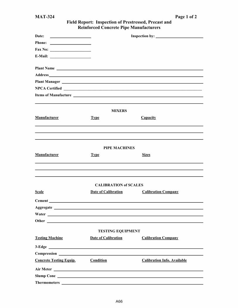
MAT-324 Page 1 of 2
Field Report: Inspection of Prestressed, Precast and
Reinforced Concrete Pipe Manufacturers
Date: Inspection by:
Phone:
Fax No: _____________________
E-Mail: _____________________
Plant Name
Address
Plant Manager
NPCA Certified _______________________________________________________________________
Items of Manufacture
MIXERS
Manufacturer Type Capacity
PIPE MACHINES
Manufacturer Type Sizes
CALIBRATION of SCALES
Scale Date of Calibration Calibration Company
Cement
Aggregate
Water
Other
TESTING EQUIPMENT
Testing Machine Date of Calibration Calibration Company
3-Edge
Compression
Concrete Testing Equip. Condition Calibration Info. Available
Air Meter
Slump Cone
Thermometers
A66
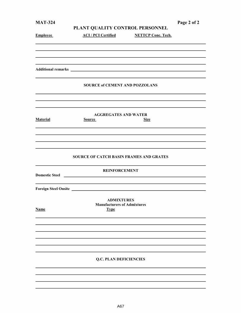
MAT-324 Page 2 of 2
PLANT QUALITY CONTROL PERSONNEL
Employee ACI / PCI Certified NETTCP Conc. Tech.
Additional remarks
SOURCE of CEMENT AND POZZOLANS
AGGREGATES AND WATER
Material Source Size
SOURCE OF CATCH BASIN FRAMES AND GRATES
REINFORCEMENT
Domestic Steel
Foreign Steel Onsite
ADMIXTURES
Manufacturers of Admixtures
Name Type
Q.C. PLAN DEFICIENCIES
A67
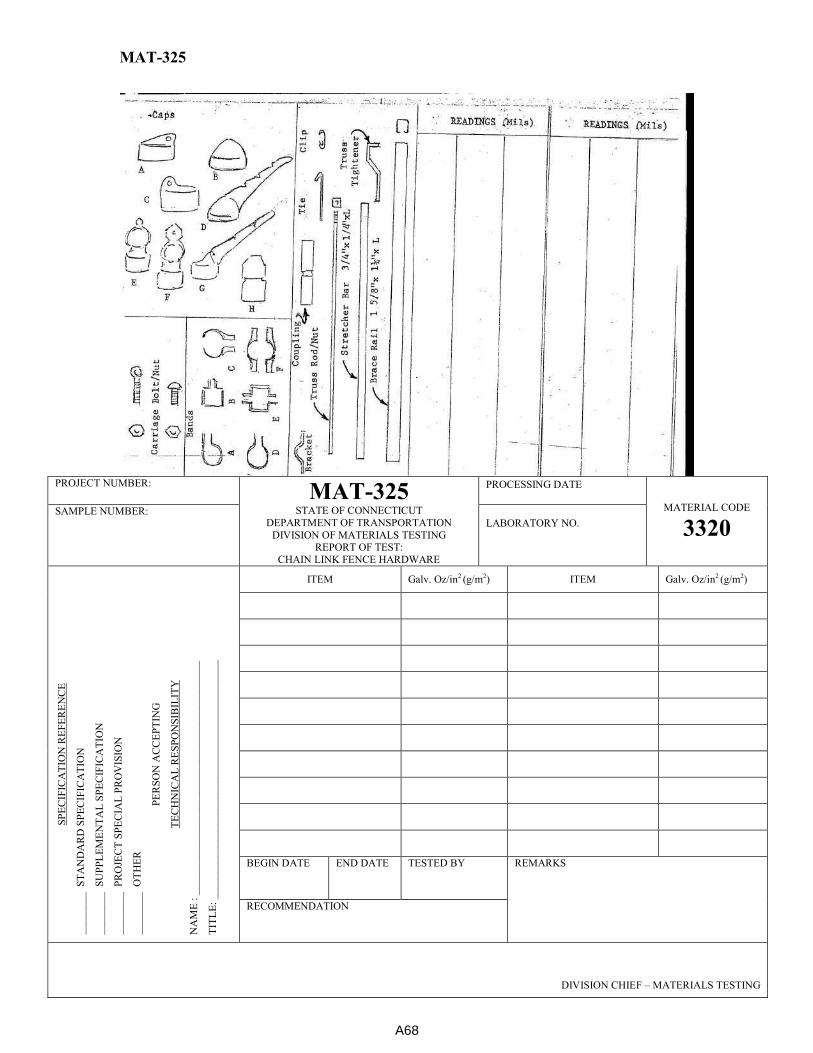
MAT-325
PROJECT NUMBER:
MAT-325 STATE OF CONNECTICUT
DEPARTMENT OF TRANSPORTATION
DIVISION OF MATERIALS TESTING REPORT OF TEST:
CHAIN LINK FENCE HARDWARE
PROCESSING DATE
MATERIAL CODE
3320 SAMPLE NUMBER:
LABORATORY NO.
SP
EC
IFIC
AT
ION
RE
FE
RE
NC
E
____
___
_
ST
AN
DA
RD
SP
EC
IFIC
AT
ION
____
___
_
SU
PP
LE
ME
NT
AL
SP
EC
IFIC
AT
ION
____
___
_
PR
OJE
CT
SP
EC
IAL
PR
OV
ISIO
N
____
___
_
OT
HE
R
PE
RS
ON
AC
CE
PT
ING
TE
CH
NIC
AL
RE
SP
ON
SIB
ILIT
Y
NA
ME
: _
__
___
___
___
___
___
___
___
___
___
___
___
___
___
__
TIT
LE
: ___
___
___
___
___
___
___
____
___
___
___
___
___
___
__
ITEM Galv. Oz/in2 (g/m2) ITEM Galv. Oz/in2 (g/m2)
BEGIN DATE END DATE TESTED BY REMARKS
RECOMMENDATION
DIVISION CHIEF – MATERIALS TESTING
A68
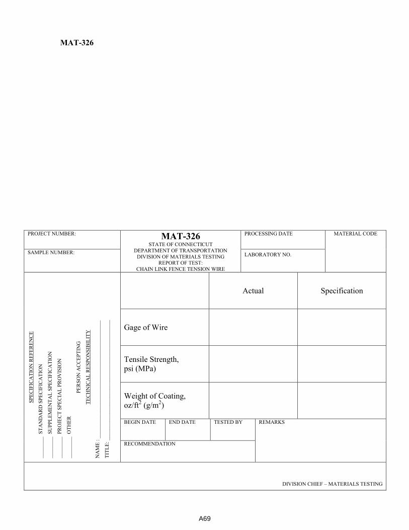
MAT-326
PROJECT NUMBER: MAT-326 STATE OF CONNECTICUT
DEPARTMENT OF TRANSPORTATION
DIVISION OF MATERIALS TESTING REPORT OF TEST:
CHAIN LINK FENCE TENSION WIRE
PROCESSING DATE
MATERIAL CODE
SAMPLE NUMBER: LABORATORY NO.
SP
EC
IFIC
AT
ION
RE
FE
RE
NC
E
____
___
_
ST
AN
DA
RD
SP
EC
IFIC
AT
ION
____
___
_
SU
PP
LE
ME
NT
AL
SP
EC
IFIC
AT
ION
____
___
_
PR
OJE
CT
SP
EC
IAL
PR
OV
ISIO
N
____
___
_
OT
HE
R
PE
RS
ON
AC
CE
PT
ING
TE
CH
NIC
AL
RE
SP
ON
SIB
ILIT
Y
NA
ME
: _
__
___
___
___
___
___
___
___
___
___
___
___
___
___
__
TIT
LE
: ___
___
___
___
___
___
___
____
___
___
___
___
___
___
__
Actual Specification
Gage of Wire
Tensile Strength,
psi (MPa)
Weight of Coating,
oz/ft2 (g/m
2)
BEGIN DATE END DATE TESTED BY REMARKS
RECOMMENDATION
DIVISION CHIEF – MATERIALS TESTING
A69
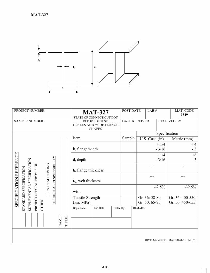
MAT-327
PROJECT NUMBER: MAT-327 STATE OF CONNECTICUT DOT
REPORT OF TEST:
H-PILES AND WIDE FLANGE
SHAPES
POST DATE LAB # MAT. CODE
3549
SAMPLE NUMBER: DATE RECEIVED RECEIVED BY
SP
EC
IFIC
AT
ION
RE
FE
RE
NC
E
__
___
___
S
TA
ND
AR
D S
PE
CIF
ICA
TIO
N
__
___
___
S
UP
PL
EM
EN
TA
L S
PE
CIF
ICA
TIO
N
__
___
___
P
RO
JEC
T S
PE
CIA
L P
RO
VIS
ION
__
___
___
O
TH
ER
PE
RS
ON
AC
CE
PT
ING
TE
CH
NIC
AL
RE
SP
ON
SIB
ILIT
Y
NA
ME
: _
__
___
___
___
___
___
__
__
___
___
___
___
___
___
__
__
TIT
LE
: _
__
___
___
___
___
___
__
__
___
___
___
___
___
___
__
__
_ Item Sample
Specification
U.S. Cust. (in) Metric (mm)
b, flange width + 1/4
- 3/16
+ 4
- 3
d, depth +1/4
-3/16
+6
-5
tf, flange thickness --- ---
tw, web thickness --- ---
wt/ft +/-2.5% +/-2.5%
Tensile Strength
(ksi, MPa)
Gr. 36: 58-80
Gr. 50: 65-95
Gr. 36: 400-550
Gr. 50: 450-655
Begin Date End Date Tested By REMARKS
DIVISION CHIEF – MATERIALS TESTING
d
b
tw
tf
A70
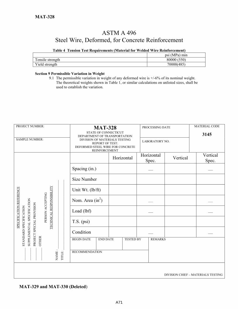
MAT-328
ASTM A 496
Steel Wire, Deformed, for Concrete Reinforcement
Table 4 Tension Test Requirements (Material for Welded Wire Reinforcement)
psi (MPa) min
Tensile strength 80000 (550)
Yield strength 70000(485)
Section 9 Permissible Variation in Weight
9.1 The permissible variation in weight of any deformed wire is +/-6% of its nominal weight.
The theoretical weights shown in Table 1, or similar calculations on unlisted sizes, shall be
used to establish the variation.
PROJECT NUMBER: MAT-328 STATE OF CONNECTICUT
DEPARTMENT OF TRANSPORTATION DIVISION OF MATERIALS TESTING
REPORT OF TEST:
DEFORMED STEEL WIRE FOR CONCRETE REINFORCEMENT
PROCESSING DATE
MATERIAL CODE
3145 SAMPLE NUMBER:
LABORATORY NO.
SP
EC
IFIC
AT
ION
RE
FE
RE
NC
E
____
___
_
ST
AN
DA
RD
SP
EC
IFIC
AT
ION
____
___
_
SU
PP
LE
ME
NT
AL
SP
EC
IFIC
AT
ION
____
___
_
PR
OJE
CT
SP
EC
IAL
PR
OV
ISIO
N
____
___
_
OT
HE
R
PE
RS
ON
AC
CE
PT
ING
TE
CH
NIC
AL
RE
SP
ON
SIB
ILIT
Y
NA
ME
: _
__
___
___
___
___
___
___
___
___
___
___
___
___
___
__
TIT
LE
: ___
___
___
___
___
___
___
____
___
___
___
___
___
___
__
Horizontal Horizontal
Spec. Vertical
Vertical
Spec.
Spacing (in.)
___
___
Size Number
Unit Wt. (lb/ft)
Nom. Area (in2)
___
___
Load (lbf)
___
___
T.S. (psi)
Condition
___
___
BEGIN DATE END DATE TESTED BY REMARKS
RECOMMENDATION
DIVISION CHIEF – MATERIALS TESTING
MAT-329 and MAT-330 (Deleted)
A71

Sample Date Tested:
Kind of Material:
Source of Supply:
Location of Source or Supply:
Sample Taken From:
Source of Supply: Rocky Hill Binder Results
Location of:
Sampled By: Original Binder Specification
Date Sampled: SG @ 25°C
Temperature ( °C) 58 64 70 76 82
Quantity Represented: Viscosity (Pa-s) @ 135°C max. 3
Lot Number: Viscosity (Pa-s) @ 165°C
Tank Number: Mixing Temperature Range
Sample Received: Compaction Temperature Range
Remarks: Complex Modulus, G* (kPa)
Phase Angle ( δ)
Original G*/sin δ @ T°C min. 1
RTFO Binder
Binder True Grade Mass change (%) -1 to +1
Temperature ( °C) 58 64 70 76 82
Complex Modulus, G* (kPa)
Phase Angle ( δ)
RTFO G*/sin δ @ T°C min. 2.2
RTFO Jnr 3.2 (kPa-1
) @ T°C max. 4.5 (S), 0.5 (E)
RTFO R3.2 @ T°C
RTFO Jnr 0.1 (kPa-1)@ T°C
RTFO Jnr Diff (%) @ T°C max. 75
Modified by an acceptable elastomeric poly? Yes (E)
PAV Binder
Temperature ( °C) 34 31 28 25 22
Complex Modulus, G* (kPa)
Phase Angle ( δ)
PAV G* sin δ @ T°C max. 5000 (S), 6000 (E)
Temperature ( °C) -6 -12 -18 -24
PAV BBR Stiffness (MPa) @ T°C max. 300
PAV BBR m-value @ T°C min. 0.3
Failure Stress
Failure Strain (%) min. 1
Laboratory: Central Lab Rocky Hill, CT State of Connecticut Department of Transportation
Bureau of Engineering & Highway Operations
Report of Test: Asphalt Binder MAT-401
Low (BBR)
T(S)-T(m)
Using Agency: ConnDOT
Standard Specifications CONNDOT: M04 Bit. Concrete, AASHTO M320 AND AASHTO M332
Procedures in conformace with AASHTO R-29
High Temp
Inter Temp
A72
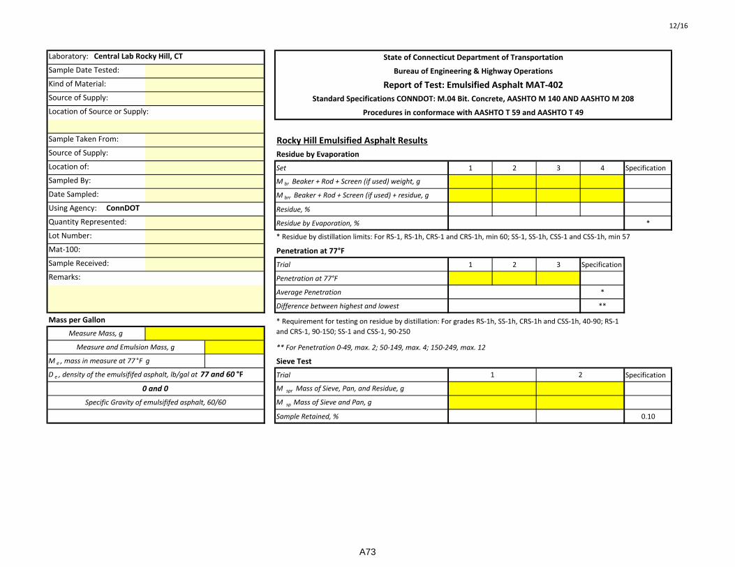
12/16
Sample Date Tested:
Kind of Material:
Source of Supply:
Location of Source or Supply:
Sample Taken From: Rocky Hill Emulsified Asphalt Results
Source of Supply: Residue by Evaporation
Location of: Set 1 2 3 4 Specification
Sampled By: M br Beaker + Rod + Screen (if used) weight, g
Date Sampled: M brr Beaker + Rod + Screen (if used) + residue, g
Residue, %
Quantity Represented: Residue by Evaporation, % *
Lot Number:
Mat-100: Penetration at 77°F
Sample Received: Trial 1 2 3 Specification
Remarks: Penetration at 77°F
Average Penetration *
Difference between highest and lowest **
Mass per Gallon
** For Penetration 0-49, max. 2; 50-149, max. 4; 150-249, max. 12
M e , mass in measure at 77 °F g Sieve Test
Trial Specification
M spr Mass of Sieve, Pan, and Residue, g
M sp Mass of Sieve and Pan, g
Sample Retained, % 0.10
Laboratory: Central Lab Rocky Hill, CT
Using Agency: ConnDOT
State of Connecticut Department of Transportation
Bureau of Engineering & Highway Operations
Report of Test: Emulsified Asphalt MAT-402
Standard Specifications CONNDOT: M.04 Bit. Concrete, AASHTO M 140 AND AASHTO M 208
Procedures in conformace with AASHTO T 59 and AASHTO T 49
Specific Gravity of emulsififed asphalt, 60/60
D e , density of the emulsififed asphalt, lb/gal at 77 and 60 °F
0 and 0
* Requirement for testing on residue by distillation: For grades RS-1h, SS-1h, CRS-1h and CSS-1h, 40-90; RS-1
and CRS-1, 90-150; SS-1 and CSS-1, 90-250Measure Mass, g
Measure and Emulsion Mass, g
* Residue by distillation limits: For RS-1, RS-1h, CRS-1 and CRS-1h, min 60; SS-1, SS-1h, CSS-1 and CSS-1h, min 57
1 2
A73

STATE OF CONNECTICUT DEPARTMENT OF TRANSPORTATION
DIVISION OF MATERIALS TESTING MAT-404 (REV 12-16)
BITUMINOUS CONCRETE PLANT INSPECTION
Page 1 of 6
Producer:
Location:
Inspected By: Date:
The mixing plant used in the preparation of bituminous concrete shall conform to the following requirements:
Plant Type: Batch Drum
Capacity Capacity Aggregates:
TYPE SOURCE OF SUPPLY TYPE SOURCE OF SUPPLY
Trap Rock
Crushed Gravel
1/4”
1/4”
3/8 ”
3/8 ”
1/2”
1/2”
3/4”
3/4”
1”
1”
1 1/4”
1 1/4”
Natural Sand
Stone Sand
Screenings
Other
A74
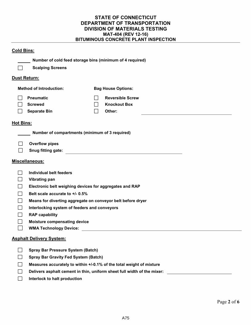
STATE OF CONNECTICUT DEPARTMENT OF TRANSPORTATION
DIVISION OF MATERIALS TESTING MAT-404 (REV 12-16)
BITUMINOUS CONCRETE PLANT INSPECTION
Page 2 of 6
Cold Bins:
Number of cold feed storage bins (minimum of 4 required)
Scalping Screens
Dust Return:
Method of Introduction: Bag House Options:
Pneumatic Reversible Screw
Screwed Knockout Box
Separate Bin Other:
Hot Bins:
Number of compartments (minimum of 3 required)
Overflow pipes
Snug fitting gate:
Miscellaneous:
Individual belt feeders
Vibrating pan
Electronic belt weighing devices for aggregates and RAP
Belt scale accurate to +/- 0.5%
Means for diverting aggregate on conveyor belt before dryer
Interlocking system of feeders and conveyors
RAP capability
Moisture compensating device
WMA Technology Device: Asphalt Delivery System:
Spray Bar Pressure System (Batch)
Spray Bar Gravity Fed System (Batch)
Measures accurately to within +/-0.1% of the total weight of mixture
Delivers asphalt cement in thin, uniform sheet full width of the mixer:
Interlock to halt production
A75
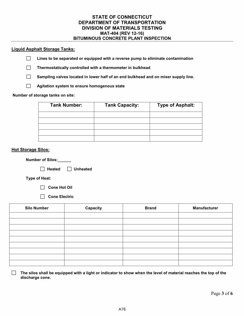
STATE OF CONNECTICUT DEPARTMENT OF TRANSPORTATION
DIVISION OF MATERIALS TESTING MAT-404 (REV 12-16)
BITUMINOUS CONCRETE PLANT INSPECTION
Page 3 of 6
Liquid Asphalt Storage Tanks:
Lines to be separated or equipped with a reverse pump to eliminate contamination
Thermostatically controlled with a thermometer in bulkhead
Sampling valves located in lower half of an end bulkhead and on mixer supply line.
Agitation system to ensure homogenous state Number of storage tanks on site:
Tank Number: Tank Capacity: Type of Asphalt:
Hot Storage Silos:
Number of Silos:
Heated Unheated Type of Heat: Cone Hot Oil Cone Electric
Silo Number Capacity Brand Manufacturer
The silos shall be equipped with a light or indicator to show when the level of material reaches the top of the discharge cone.
A76
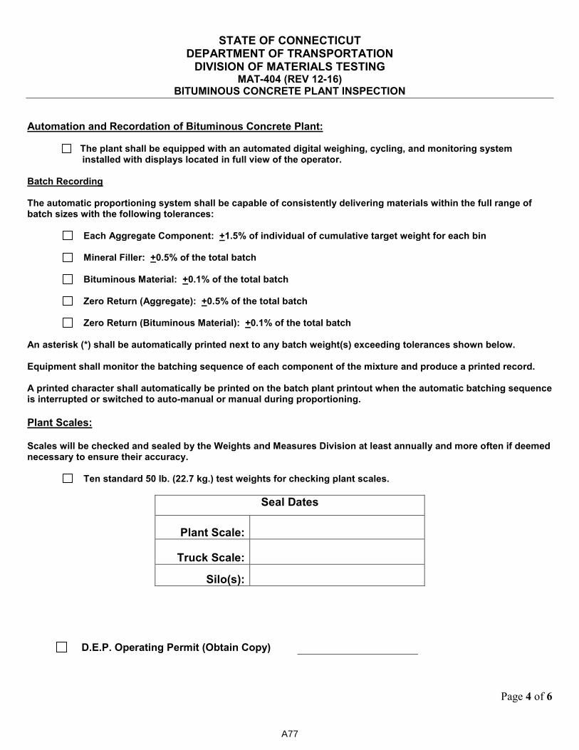
STATE OF CONNECTICUT DEPARTMENT OF TRANSPORTATION
DIVISION OF MATERIALS TESTING MAT-404 (REV 12-16)
BITUMINOUS CONCRETE PLANT INSPECTION
Page 4 of 6
Automation and Recordation of Bituminous Concrete Plant:
The plant shall be equipped with an automated digital weighing, cycling, and monitoring system installed with displays located in full view of the operator.
Batch Recording The automatic proportioning system shall be capable of consistently delivering materials within the full range of batch sizes with the following tolerances:
Each Aggregate Component: +1.5% of individual of cumulative target weight for each bin
Mineral Filler: +0.5% of the total batch
Bituminous Material: +0.1% of the total batch
Zero Return (Aggregate): +0.5% of the total batch
Zero Return (Bituminous Material): +0.1% of the total batch An asterisk (*) shall be automatically printed next to any batch weight(s) exceeding tolerances shown below. Equipment shall monitor the batching sequence of each component of the mixture and produce a printed record. A printed character shall automatically be printed on the batch plant printout when the automatic batching sequence is interrupted or switched to auto-manual or manual during proportioning.
Plant Scales: Scales will be checked and sealed by the Weights and Measures Division at least annually and more often if deemed necessary to ensure their accuracy.
Ten standard 50 lb. (22.7 kg.) test weights for checking plant scales.
Seal Dates
Plant Scale:
Truck Scale:
Silo(s):
D.E.P. Operating Permit (Obtain Copy)
A77
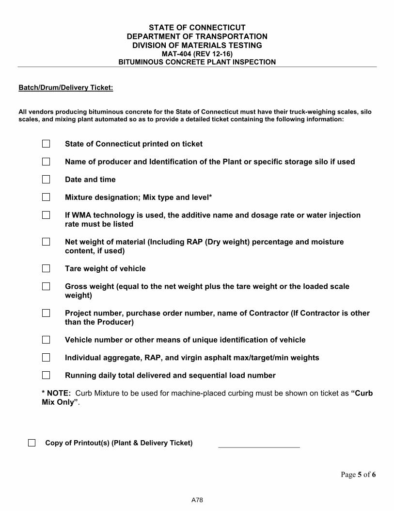
STATE OF CONNECTICUT DEPARTMENT OF TRANSPORTATION
DIVISION OF MATERIALS TESTING MAT-404 (REV 12-16)
BITUMINOUS CONCRETE PLANT INSPECTION
Page 5 of 6
Batch/Drum/Delivery Ticket:
All vendors producing bituminous concrete for the State of Connecticut must have their truck-weighing scales, silo scales, and mixing plant automated so as to provide a detailed ticket containing the following information:
State of Connecticut printed on ticket
Name of producer and Identification of the Plant or specific storage silo if used
Date and time
Mixture designation; Mix type and level*
If WMA technology is used, the additive name and dosage rate or water injection
rate must be listed
Net weight of material (Including RAP (Dry weight) percentage and moisture content, if used)
Tare weight of vehicle
Gross weight (equal to the net weight plus the tare weight or the loaded scale
weight)
Project number, purchase order number, name of Contractor (If Contractor is other than the Producer)
Vehicle number or other means of unique identification of vehicle
Individual aggregate, RAP, and virgin asphalt max/target/min weights
Running daily total delivered and sequential load number
* NOTE: Curb Mixture to be used for machine-placed curbing must be shown on ticket as “Curb Mix Only”.
Copy of Printout(s) (Plant & Delivery Ticket)
A78
STATE OF CONNECTICUT DEPARTMENT OF TRANSPORTATION
DIVISION OF MATERIALS TESTING MAT-404 (REV 12-16)
BITUMINOUS CONCRETE PLANT INSPECTION
Page 6 of 6
Please note any variations/comments from inspection below:
A79
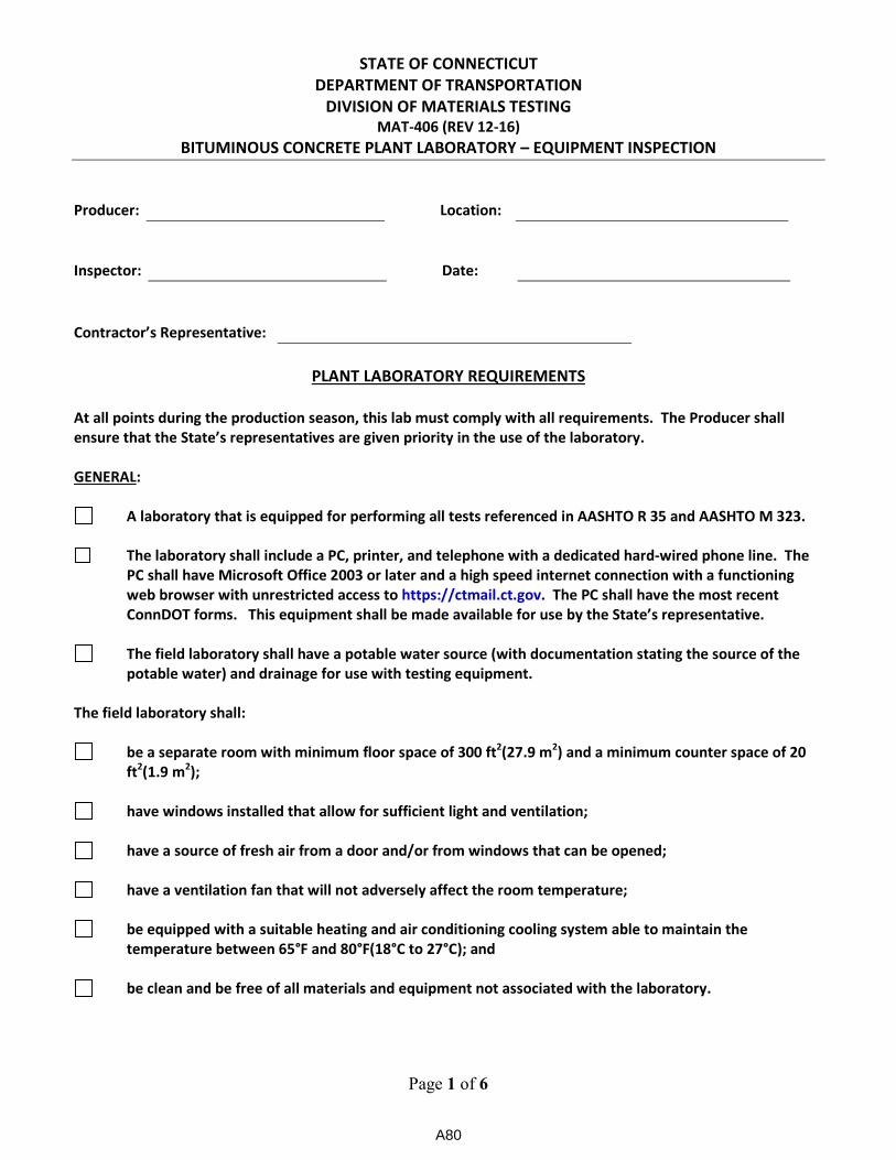
STATE OF CONNECTICUT
DEPARTMENT OF TRANSPORTATION
DIVISION OF MATERIALS TESTING
MAT-406 (REV 12-16)
BITUMINOUS CONCRETE PLANT LABORATORY – EQUIPMENT INSPECTION
Page 1 of 6
Producer:
Location:
Inspector:
Date:
Contractor’s Representative:
PLANT LABORATORY REQUIREMENTS
At all points during the production season, this lab must comply with all requirements. The Producer shall
ensure that the State’s representatives are given priority in the use of the laboratory.
GENERAL:
A laboratory that is equipped for performing all tests referenced in AASHTO R 35 and AASHTO M 323.
The laboratory shall include a PC, printer, and telephone with a dedicated hard-wired phone line. The
PC shall have Microsoft Office 2003 or later and a high speed internet connection with a functioning
web browser with unrestricted access to https://ctmail.ct.gov. The PC shall have the most recent
ConnDOT forms. This equipment shall be made available for use by the State’s representative.
The field laboratory shall have a potable water source (with documentation stating the source of the
potable water) and drainage for use with testing equipment.
The field laboratory shall:
be a separate room with minimum floor space of 300 ft2(27.9 m
2) and a minimum counter space of 20
ft2(1.9 m
2);
have windows installed that allow for sufficient light and ventilation;
have a source of fresh air from a door and/or from windows that can be opened;
have a ventilation fan that will not adversely affect the room temperature;
be equipped with a suitable heating and air conditioning cooling system able to maintain the
temperature between 65°F and 80°F(18°C to 27°C); and
be clean and be free of all materials and equipment not associated with the laboratory.
A80

STATE OF CONNECTICUT
DEPARTMENT OF TRANSPORTATION
DIVISION OF MATERIALS TESTING
MAT-406 (REV 12-16)
BITUMINOUS CONCRETE PLANT LABORATORY – EQUIPMENT INSPECTION
Page 2 of 6
EQUIPMENT:
A list of laboratory equipment used in acceptance testing processes including, but not limited to,
balances, scales, manometer/vacuum gauge, thermometers, gyratory compactor. The list shall include
calibration and/or inspection dates in accordance with AASHTO R 18.
Paint brush: 1 in to 1 ½ in (25 mm to 38 mm) wide.
Hand brush: suitable for cleaning sieves.
Two, 6 in. (152 mm) spatulas.
Two stem thermometers for mix temperatures with a range of 50°F to 450°F (10°C to 230°C).
Thermometers: Calibrated liquid-in-glass, total immersion type, of suitable range with gradations at
least over 0.2°F (0.1°C) and a maximum scale error of 0.2°F (0.1°C) as prescribed in ASTM Specification
E2.
Vacuum pump or water aspirator for evacuation of air from the container: The vacuum pump or water
aspirator shall be equipped with a needle valve to maintain constant vacuum.
Water bath: Shall be capable of maintaining constant temperature between 20 and 30°C and constant
suitable water level.
Residual pressure manometers or vacuum gauges (Mercury manometers are not allowed for use.):
See diagram below for proper placement of manometer or gauge.
Date manometer/gauge was last standardized:
Date manometer/gauge was last standardized:
A81
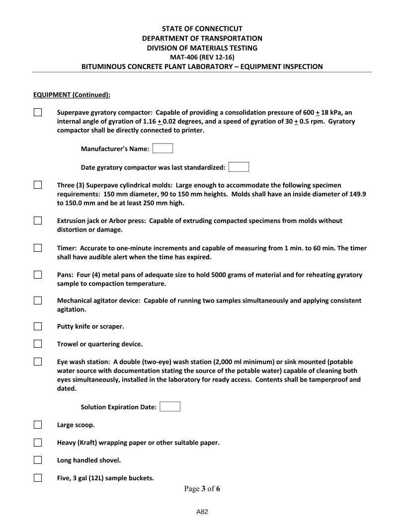
STATE OF CONNECTICUT
DEPARTMENT OF TRANSPORTATION
DIVISION OF MATERIALS TESTING
MAT-406 (REV 12-16)
BITUMINOUS CONCRETE PLANT LABORATORY – EQUIPMENT INSPECTION
Page 3 of 6
EQUIPMENT (Continued):
Superpave gyratory compactor: Capable of providing a consolidation pressure of 600 + 18 kPa, an
internal angle of gyration of 1.16 + 0.02 degrees, and a speed of gyration of 30 + 0.5 rpm. Gyratory
compactor shall be directly connected to printer.
Manufacturer’s Name:
Date gyratory compactor was last standardized:
Three (3) Superpave cylindrical molds: Large enough to accommodate the following specimen
requirements: 150 mm diameter, 90 to 150 mm heights. Molds shall have an inside diameter of 149.9
to 150.0 mm and be at least 250 mm high.
Extrusion jack or Arbor press: Capable of extruding compacted specimens from molds without
distortion or damage.
Timer: Accurate to one-minute increments and capable of measuring from 1 min. to 60 min. The timer
shall have audible alert when the time has expired.
Pans: Four (4) metal pans of adequate size to hold 5000 grams of material and for reheating gyratory
sample to compaction temperature.
Mechanical agitator device: Capable of running two samples simultaneously and applying consistent
agitation.
Putty knife or scraper.
Trowel or quartering device.
Eye wash station: A double (two-eye) wash station (2,000 ml minimum) or sink mounted (potable
water source with documentation stating the source of the potable water) capable of cleaning both
eyes simultaneously, installed in the laboratory for ready access. Contents shall be tamperproof and
dated.
Solution Expiration Date:
Large scoop.
Heavy (Kraft) wrapping paper or other suitable paper.
Long handled shovel.
Five, 3 gal (12L) sample buckets.
A82
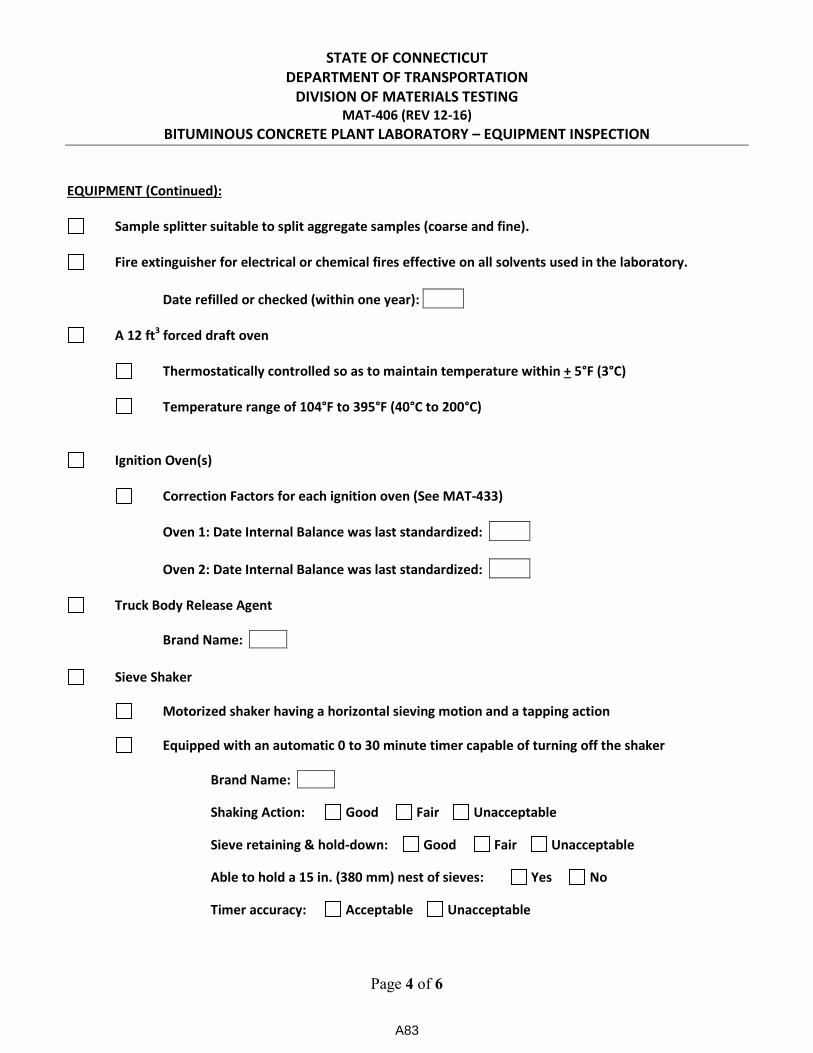
STATE OF CONNECTICUT
DEPARTMENT OF TRANSPORTATION
DIVISION OF MATERIALS TESTING
MAT-406 (REV 12-16)
BITUMINOUS CONCRETE PLANT LABORATORY – EQUIPMENT INSPECTION
Page 4 of 6
EQUIPMENT (Continued):
Sample splitter suitable to split aggregate samples (coarse and fine).
Fire extinguisher for electrical or chemical fires effective on all solvents used in the laboratory.
Date refilled or checked (within one year):
A 12 ft3 forced draft oven
Thermostatically controlled so as to maintain temperature within + 5°F (3°C)
Temperature range of 104°F to 395°F (40°C to 200°C)
Ignition Oven(s)
Correction Factors for each ignition oven (See MAT-433)
Oven 1: Date Internal Balance was last standardized:
Oven 2: Date Internal Balance was last standardized:
Truck Body Release Agent
Brand Name:
Sieve Shaker
Motorized shaker having a horizontal sieving motion and a tapping action
Equipped with an automatic 0 to 30 minute timer capable of turning off the shaker
Brand Name:
Shaking Action: Good Fair Unacceptable
Sieve retaining & hold-down: Good Fair Unacceptable
Able to hold a 15 in. (380 mm) nest of sieves: Yes No
Timer accuracy: Acceptable Unacceptable
A83

STATE OF CONNECTICUT
DEPARTMENT OF TRANSPORTATION
DIVISION OF MATERIALS TESTING
MAT-406 (REV 12-16)
BITUMINOUS CONCRETE PLANT LABORATORY – EQUIPMENT INSPECTION
Page 5 of 6
EQUIPMENT (Continued):
Sieves (U.S. Standard)
Set of 8 in. (200 mm) sieves
Set of 12 in. (300 mm) sieves
A minimum of one for each of the above sieve sizes:
Pan (may be half height) #200 (75 µm) (may be half height)
#100 (150µm) (may be half height) #50 (300µm) (may be half height)
#30 (600µm) (may be half height) #16 (1.18mm) (may be half height)
#8 (2.36mm) (may be half height) #4 (4.75 mm)
3/8” (6.3mm) ½” (9.5 mm)
¾” (19 mm) 1” (25 mm)
1 1/2” (37.5 mm) 2” (50mm)
Electronic Balances
Two 20 kg (42 lb) capacity scales with sufficient sensitivity to read to + 0.1 grams. For the
AASHTO T 209 - mass determination in water method, one of the balances shall be equipped
with a suitable suspension apparatus and holder to permit weighing the sample while
suspended from the center of the scale plan or balance.
Brand Name Type Last Calibration Date
A84
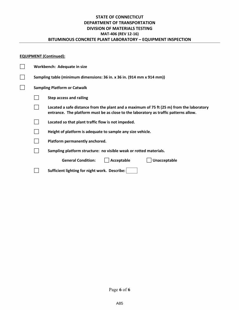
STATE OF CONNECTICUT
DEPARTMENT OF TRANSPORTATION
DIVISION OF MATERIALS TESTING
MAT-406 (REV 12-16)
BITUMINOUS CONCRETE PLANT LABORATORY – EQUIPMENT INSPECTION
Page 6 of 6
EQUIPMENT (Continued):
Workbench: Adequate in size
Sampling table (minimum dimensions: 36 in. x 36 in. (914 mm x 914 mm))
Sampling Platform or Catwalk
Step access and railing
Located a safe distance from the plant and a maximum of 75 ft (25 m) from the laboratory
entrance. The platform must be as close to the laboratory as traffic patterns allow.
Located so that plant traffic flow is not impeded.
Height of platform is adequate to sample any size vehicle.
Platform permanently anchored.
Sampling platform structure: no visible weak or rotted materials.
General Condition: Acceptable Unacceptable
Sufficient lighting for night work. Describe:
A85

STATE OF CONNECTICUT DEPARTMENT OF TRANSPORTATION Page 1 of 1
DIVISION OF MATERIALS TESTING
MAT-407 (REV 12-16) PLANT AND LABORATORY DEFICIENCY REPORT
Producer:
Location:
Inspector:
Date:
On the above date, the following deficiencies were found in your Plant/Laboratory.
Item Deficiency Correction/Response
Please make the necessary corrections before the first day of production and email responses to the following
email address: [email protected].
Failure to correct the indicated deficiencies may result in loss of State approval.
1)
2)
3)
4)
5)
6)
7)
8)
9)
10)
A86
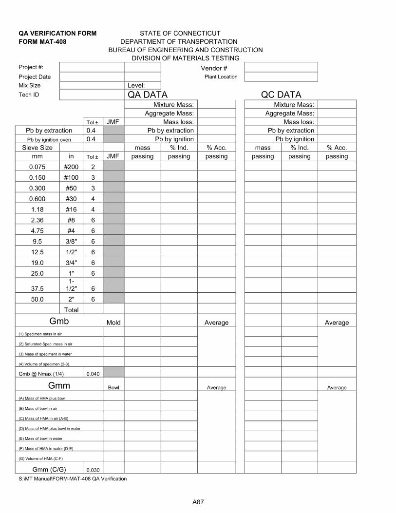
QA VERIFICATION FORM STATE OF CONNECTICUT
FORM MAT-408 DEPARTMENT OF TRANSPORTATION
BUREAU OF ENGINEERING AND CONSTRUCTION
DIVISION OF MATERIALS TESTING
Project #: Vendor #
Project Date Plant Location
Mix Size Level:
Tech ID QA DATA QC DATA
Mixture Mass: Mixture Mass:
Aggregate Mass: Aggregate Mass:
Tol ± JMF Mass loss: Mass loss:
Pb by extraction 0.4 Pb by extraction Pb by extraction
Pb by ignition oven 0.4 Pb by ignition Pb by ignition
Sieve Size mass % Ind. % Acc. mass % Ind. % Acc.
mm in Tol ± JMF passing passing passing passing passing passing
0.075 #200 2
0.150 #100 3
0.300 #50 3
0.600 #30 4
1.18 #16 4
2.36 #8 6
4.75 #4 6
9.5 3/8" 6
12.5 1/2" 6
19.0 3/4" 6
25.0 1" 6
37.5 1-
1/2" 6
50.0 2" 6
Total
Gmb Mold Average
Average
(1) Specimen mass in air
(2) Saturated Spec. mass in air
(3) Mass of speciment in water
(4) Volume of specimen (2-3)
Gmb @ Nmax (1/4) 0.040
Gmm Bowl Average Average
(A) Mass of HMA plus bowl
(B) Mass of bowl in air
(C) Mass of HMA in air (A-B)
(D) Mass of HMA plus bowl in water
(E) Mass of bowl in water
(F) Mass of HMA in water (D-E)
(G) Volume of HMA (C-F)
Gmm (C/G) 0.030
S:\MT Manual\FORM-MAT-408 QA Verification
A87
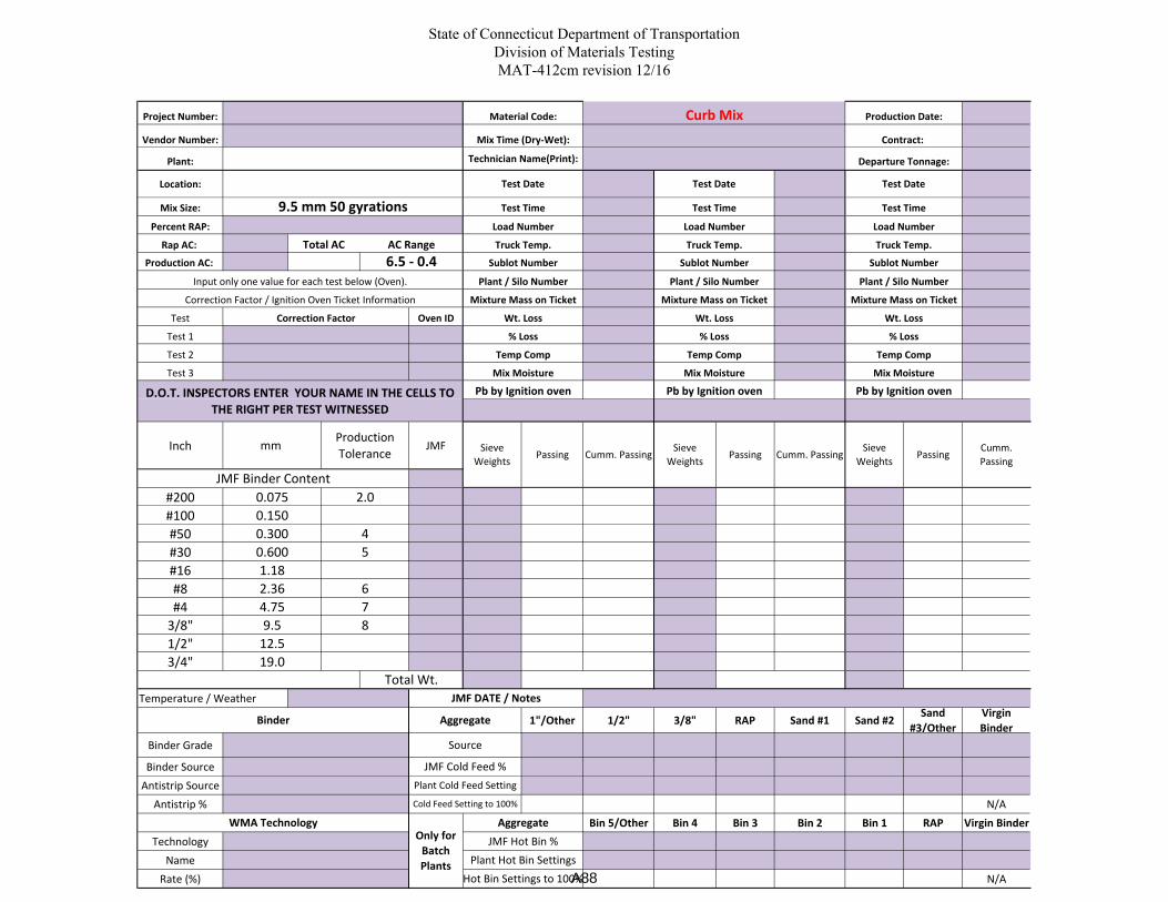
State of Connecticut Department of Transportation
Division of Materials Testing
MAT-412cm revision 12/16
Project Number:
Vendor Number:
Plant:
Location:
Mix Size:
Percent RAP:
Rap AC:
Production AC:
Test Oven ID
Test 1
Test 2
Test 3
Inch JMF
#200
#100
#50
#30
#16
#8
#4
3/8"
1/2"
3/4"
Temperature / Weather
1"/Other 1/2" 3/8" RAP Sand #1 Sand #2Sand
#3/Other
Virgin
Binder
Binder Grade
Binder Source
Antistrip Source
Antistrip % N/A
Bin 5/Other Bin 4 Bin 3 Bin 2 Bin 1 RAP Virgin Binder
Technology
Name
Rate (%) N/A
Sieve
WeightsPassing Cumm. Passing
Sieve
WeightsPassing Cumm. Passing
0.150
4.75
0.600
0.075
Hot Bin Settings to 100%
Aggregate
JMF Hot Bin %
Source
Plant Cold Feed Setting
Plant Hot Bin Settings
Only for
Batch
Plants
Binder
WMA Technology Aggregate
Cold Feed Setting to 100%
JMF DATE / Notes
8
2.36
Total Wt.
JMF Cold Feed %
D.O.T. INSPECTORS ENTER YOUR NAME IN THE CELLS TO
THE RIGHT PER TEST WITNESSED
0.300
9.5
1.18
mm
2.0
Production
Tolerance
JMF Binder Content
19.0
4
6
7
12.5
5
Mix Moisture
Pb by Ignition oven
Mix Moisture
Pb by Ignition oven
% Loss
Temp Comp
Pb by Ignition oven
Mix Moisture
Sieve
WeightsPassing
Cumm.
Passing
% Loss % Loss
Wt. Loss Wt. Loss
Temp CompTemp Comp
Truck Temp.
Load Number
Truck Temp. Truck Temp.
Load Number Load Number
Contract:
Departure Tonnage:
Test Time Test Time
Test DateTest Date
Production Date:Curb Mix
Test Time
Material Code:
Mix Time (Dry-Wet):
Total AC
6.5 - 0.4 Sublot Number
9.5 mm 50 gyrations
Test Date
AC Range
Technician Name(Print):
Correction Factor / Ignition Oven Ticket Information
Input only one value for each test below (Oven).
Mixture Mass on Ticket
Correction Factor
Sublot Number Sublot Number
Plant / Silo NumberPlant / Silo Number
Wt. Loss
Plant / Silo Number
Mixture Mass on Ticket Mixture Mass on Ticket
A88

State of Connecticut Department of Transportation Division Of Materials Testing
MAT-412s revision 11/16
Project Number: Rt/Town
Vendor Number: Lot
Plant / Location:
Test Date/Time Test Date/TimeTest
Date/Time
Percent RAP:
Corrected Rap Pb:
Virgin Pb:
Test 1
Test 2
Test 3
InchControl
Points
Prod Range
for +Adj
JMF
Target
#200
#100
#50
#30
#16
#8
#4
3/8"
1/2"
3/4"
1"
1 1/2"
2"
JMF Date:
JMF Gsa:
JMF Gsb:
JMF Pba:
Gmm (AASHTO T 209) JMF Gmm 0.030
1.0 4.0
VMA (AASHTO R 35) 1.0
Calculated Gsb from Gse / INFORMATION ONLY
VMA from calculated Gsb / INFORMATION ONLY
HEIGHT (Hi) @ Nini
Density to Nini
HEIGHT(Hd) @ Ndes
Temperature / Weather
1"/Other 1/2" 3/8" RAP Sand #1 Sand #2Sand
#3/OtherVirgin Binder
Binder Grade
Binder Source
Antistrip Source
Antistrip % N/A
Bin 5/Other Bin 4 Bin 3 Bin 2 Bin 1 RAP Virgin Binder
Technology
Name
Rate (%) N/A
Today Results Complete Lot ?
Mix Size:RAP Daily (dried & w/o
IO CF) Ignition Oven Pb
D.O.T. INSPECTORS ENTER YOUR NAME IN THE CELLS TO THE RIGHT PER TEST
WITNESSED
Correction Factor / Ignition Oven Ticket Information
Test Correction Factor Oven ID
Type of Lot
Gse-(0.8/0.6)*(JMG Gsa-JMFGsb)
From Gsb(F=0.6 / F=0.8)
Va (100-(Gmb @ Ndes / Gmm)*100))
Gmb @ Ndes (AASHTO T 166)
Sieve
WeightsTotal Binder Content
0.600
0.300
12.5
Specimen mass in air
% Loss
Temp Comp
Pb from Plant/Truck Ticket
Mixture Mass on Ticket
Wt. Loss
Ext. Weight After Test
Total Wt.
Mass of HMA plus bowl in air (A)
Less mass of bowl in air
Volume of HMA
4.75
Pb Difference
19.0
Less mass of specimen in water (J)
Ext. Weight After Test
Pb by AASHTO T 308
Mix Moisture (T 329)
Wt. Loss
Mixture Mass on Ticket
Mix Moisture (T 329)
Pb by AASHTO T 308
Ext. Weight After Test
Temp Comp
Mix Moisture (T 329)
Sieve
WeightsPassing
Pb Difference Pb Difference
Sieve Weights Passing Passing
/ Technician Name(Print):
Load Number Load Number
Gyro Temp. (1)-(2) Gyro Temp. (1)-(2) Gyro Temp. (1)-(2)
Estimated Total Project Tonnage for mix
Mix Time (Dry-Wet): NETTCP ID #: Contract:
Material Code: Production Date:Gyrations:
Daily Departure Tonnage
in Lot :
Truck Temp.
Minimum ACTotal AC
Sublot Number Sublot Number
Truck Temp.
JMF RAP IO CF Silo NumberSilo Number
Mixture Mass on Ticket
Wt. Loss
Cumm.
Passing
(AASHTO
T 30)
% Loss
Temp Comp
Pb by AASHTO T 308
Pb from Plant/Truck TicketPb from Plant/Truck Ticket
Volume of specimen (I-J)
Cumm.
Passing
(AASHTO
T 30)
9.5
mm
0.150
Cumm.
Passing
(AASHTO
T 30)
Less mass of bowl in water
Mass of HMA in water
Mass of HMA in air
Mass of HMA plus bowl in water
Saturated specimen mass in air (I)
% Loss
Info only: VMA(Pb ticket, Est Gsb
from Gse)
50.0
0.075
37.5
2.36
Truck Temp.
Plant / Silo Number
Load Number
Binder
Pba
Aggregate
Cold Feed Setting to 100%
JMF Cold Feed %
Sublot Number
VFA
Gse
JMF Changes / Notes
Hot Bin Settings to 100%
Aggregate
JMF Hot Bin %
Source
Plant Hot Bin Settings
Only for
Batch
Plants
Plant Cold Feed Setting
WMA Technology
1.18
25.0
A89
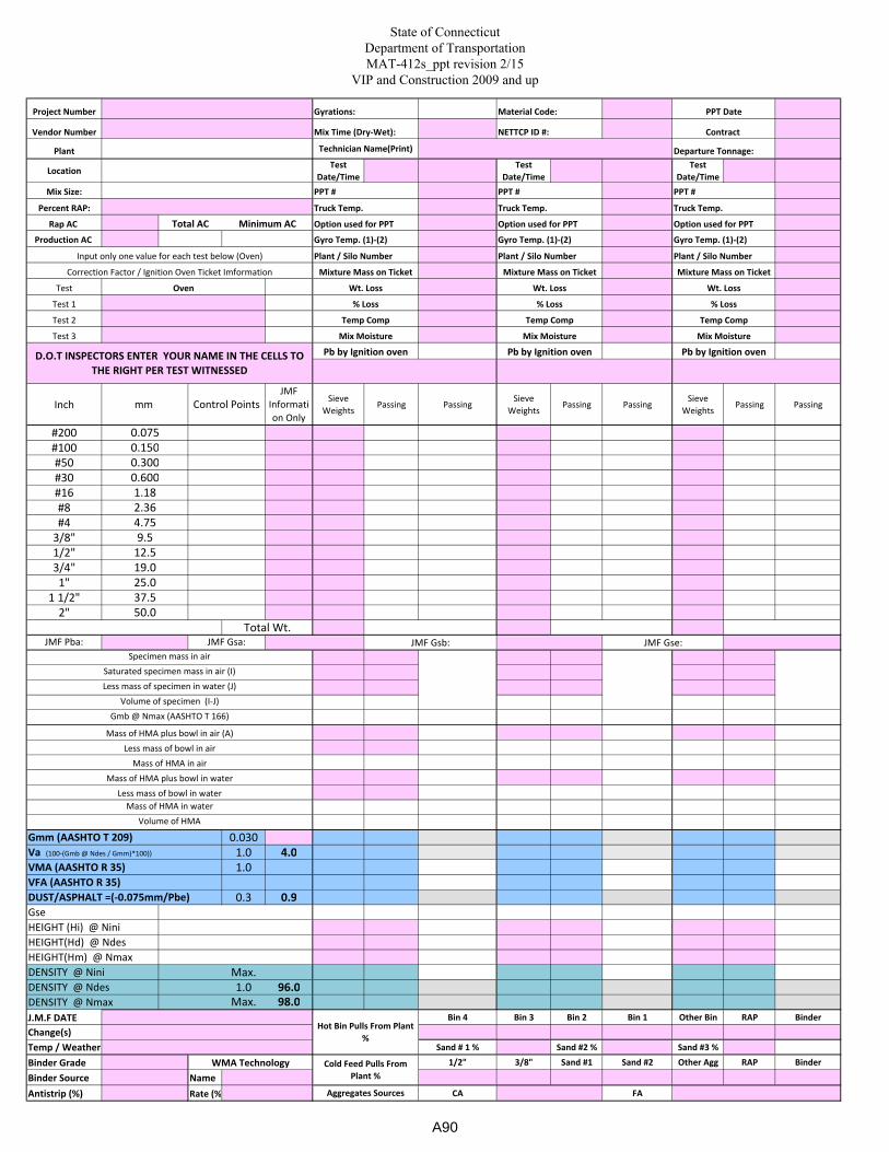
State of Connecticut
Department of Transportation
MAT-412s_ppt revision 2/15
VIP and Construction 2009 and up
Project Number
Vendor Number
Plant
LocationTest
Date/Time
Test
Date/Time
Test
Date/Time
Mix Size:
Percent RAP:
Rap AC
Production AC
Test
Test 1
Test 2
Test 3
Inch
JMF
Informati
on Only
Sieve
WeightsPassing Passing
Sieve
WeightsPassing Passing
Sieve
WeightsPassing Passing
#200
#100
#50
#30
#16
#8
#4
3/8"
1/2"
3/4"
1"
1 1/2"
2"
JMF Pba:
Gmm (AASHTO T 209) 0.030 1.0 4.0
VMA (AASHTO R 35) 1.0 VFA (AASHTO R 35) DUST/ASPHALT =(-0.075mm/Pbe) 0.3 0.9 Gse
HEIGHT (Hi) @ Nini
HEIGHT(Hd) @ Ndes
HEIGHT(Hm) @ Nmax
DENSITY @ Nini Max. DENSITY @ Ndes 1.0 96.0 DENSITY @ Nmax Max. 98.0
J.M.F DATE Bin 4 Bin 3 Bin 2 Bin 1 Other Bin RAP Binder
Change(s)
Temp / Weather Sand # 1 % Sand #2 % Sand #3 %
Binder Grade 1/2" 3/8" Sand #1 Sand #2 Other Agg RAP Binder
Binder Source Name
Antistrip (%) Rate (%) CA FA
Va (100-(Gmb @ Ndes / Gmm)*100))
WMA Technology
Hot Bin Pulls From Plant
%
Cold Feed Pulls From
Plant %
Aggregates Sources
JMF Gsb: JMF Gse:
Less mass of bowl in air
Less mass of bowl in water
Volume of specimen (I-J)
Wt. Loss Wt. Loss Wt. Loss
Mix Moisture
Mass of HMA plus bowl in air (A)
Pb by Ignition oven
Mixture Mass on Ticket Mixture Mass on Ticket Mixture Mass on Ticket
Oven
Gyro Temp. (1)-(2) Gyro Temp. (1)-(2)
Input only one value for each test below (Oven) Plant / Silo Number Plant / Silo Number
Correction Factor / Ignition Oven Ticket Imformation
Plant / Silo Number
Gyro Temp. (1)-(2)
Gyrations:
Truck Temp.
Technician Name(Print)
Mix Time (Dry-Wet): NETTCP ID #: Contract
Material Code: PPT Date
PPT # PPT # PPT #
Departure Tonnage:
Option used for PPT Option used for PPT
Truck Temp. Truck Temp.
Minimum ACTotal AC Option used for PPT
Temp Comp Temp Comp
D.O.T INSPECTORS ENTER YOUR NAME IN THE CELLS TO
THE RIGHT PER TEST WITNESSED
Pb by Ignition oven
% Loss % Loss
Mix MoistureMix Moisture
% Loss
Temp Comp
Pb by Ignition oven
0.600
37.5
0.300
12.5
19.0
25.0
2.36
1.18
mm
Volume of HMA
0.075
9.5
4.75
Control Points
0.150
50.0
Less mass of specimen in water (J)
JMF Gsa:
Total Wt.
Gmb @ Nmax (AASHTO T 166)
Mass of HMA in water
Mass of HMA in air
Mass of HMA plus bowl in water
Specimen mass in air
Saturated specimen mass in air (I)
A90
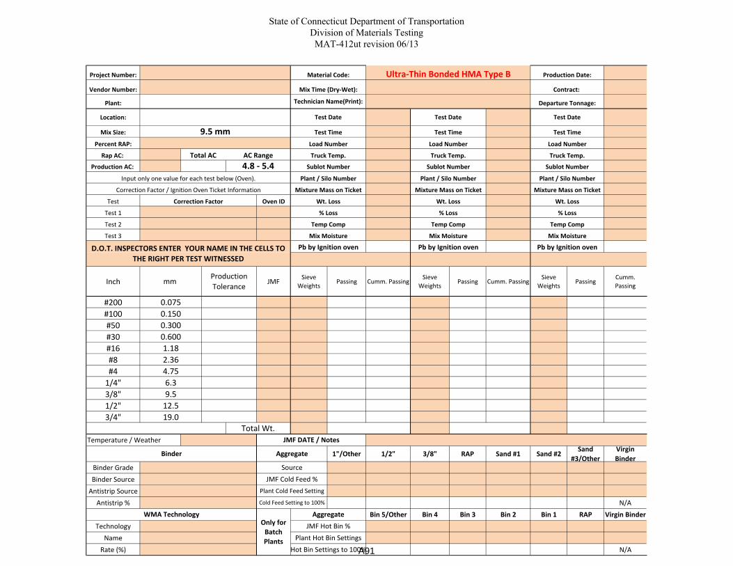
State of Connecticut Department of Transportation
Division of Materials Testing
MAT-412ut revision 06/13
Project Number:
Vendor Number:
Plant:
Location:
Mix Size:
Percent RAP:
Rap AC:
Production AC:
Test Oven ID
Test 1
Test 2
Test 3
Inch JMFSieve
WeightsPassing Cumm. Passing
Sieve
WeightsPassing Cumm. Passing
Sieve
WeightsPassing
Cumm.
Passing
#200
#100
#50
#30
#16
#8
#4
1/4"
3/8"
1/2"
3/4"
Temperature / Weather
1"/Other 1/2" 3/8" RAP Sand #1 Sand #2Sand
#3/Other
Virgin
Binder
Binder Grade
Binder Source
Antistrip Source
Antistrip % N/A
Bin 5/Other Bin 4 Bin 3 Bin 2 Bin 1 RAP Virgin Binder
Technology
Name
Rate (%) N/A
JMF DATE / Notes
Hot Bin Settings to 100%
Aggregate
JMF Hot Bin %
Source
Plant Cold Feed Setting
Binder
WMA Technology Aggregate
Cold Feed Setting to 100%
0.150
4.75
0.600
2.36
Total Wt.
JMF Cold Feed %
Plant Hot Bin Settings
Only for
Batch
Plants
0.300
9.5
12.5
1.18
mm
Production
Tolerance
0.075
19.0
6.3
Temp Comp
Mix MoistureMix Moisture
Pb by Ignition oven
Mix Moisture
Temp Comp
% Loss
Temp Comp
Pb by Ignition ovenD.O.T. INSPECTORS ENTER YOUR NAME IN THE CELLS TO
THE RIGHT PER TEST WITNESSED
Pb by Ignition oven
Mixture Mass on Ticket Mixture Mass on Ticket
% Loss % Loss
Wt. Loss Wt. Loss
Truck Temp.
Load Number
Truck Temp. Truck Temp.
Load Number Load Number
Contract:
Departure Tonnage:
Test Time Test Time
Test DateTest Date
Production Date:Ultra-Thin Bonded HMA Type B
Test Time
Material Code:
Mix Time (Dry-Wet):
Total AC
4.8 - 5.4 Sublot Number
9.5 mm
Test Date
AC Range
Technician Name(Print):
Correction Factor / Ignition Oven Ticket Information
Input only one value for each test below (Oven).
Mixture Mass on Ticket
Correction Factor
Sublot Number Sublot Number
Plant / Silo NumberPlant / Silo Number
Wt. Loss
Plant / Silo Number
A91
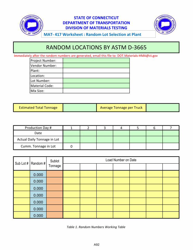
Immediately after the random numbers are generated, email this file to: [email protected]
Estimated Total Tonnage not exceed 3500
1 2 3 4 5 6 7
0
0.000
0.000
0.000
0.000
0.000
0.000
0.000
Material Code:
Vendor Number:
Cumm. Tonnage in Lot
Form MAT-418
Table 1. Random Numbers Working Table
Sublot
Tonnage
Actual Daily Tonnage in Lot
Load Number on Date
STATE OF CONNECTICUT
DEPARTMENT OF TRANSPORTATION
DIVISION OF MATERIALS TESTING
Estimated Total Tonnage
RANDOM LOCATIONS BY ASTM D-3665
Project Number:
Lot Number:
Average Tonnage per Truck
Random #
Date
Mix Size:
Production Day #
Sub Lot #
Location:
Plant:
MAT- 417 Worksheet : Random Lot Selection at Plant
A92

12/16
Mix
Plant Information
Vendor Number:
Aggregate Properties
Mix Properties
Gse 0.025
Dust/Pbe NA
Density to Nini 1.5
Pba 0.6
Factor NA
VMA 1.3
VFA 6.0
Gmm 0.022
1.3
Difference Tolerance
Gmb
JMF Target DMT Result
Va
FAA 0.8
0.020
Binder Content (%)
Gsa 0.025
SE 15
19 4
Gsb 0.028
9.5 5
12.5 4
2.36 5
4.75 5
0.6 4
1.18 4
0.15 3
0.3 3
Difference Tolerance
0.075 1.0
Plant:
Location:
JMF Target DMT Result
State of Connecticut
Department of Transportation
Division of Materials Testing - Job Mix Formula Verification
Form MAT-418
A93

STATE OF CONNECTICUT DEPARTMENT OF TRANSPORTATION
DIVISION OF MATERIALS TESTING
MAT-419 (REV 2-15) Checklist: QC Plan for FA (Reference M.04.01-2) Page 1 of 7
Quality Control Plan for Fine Aggregates (QCPFA) used in HMA
1. Basic Information A. Origin of Materials
1. Name and address of property owner or lessee.
Name
Address
2. Name, title, and telephone number of company contact person.
Name
Title
Telephone number
3. Name, title, telephone number and certifications, if applicable, of the person(s) responsible for the
QCPFA.
Name
Title
Telephone number
Certifications
Name
Title
Telephone number
Certifications
A94
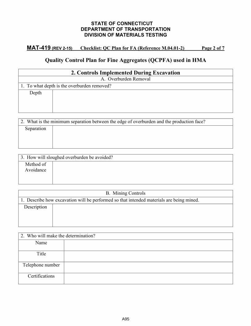
STATE OF CONNECTICUT DEPARTMENT OF TRANSPORTATION
DIVISION OF MATERIALS TESTING
MAT-419 (REV 2-15) Checklist: QC Plan for FA (Reference M.04.01-2) Page 2 of 7
Quality Control Plan for Fine Aggregates (QCPFA) used in HMA
2. Controls Implemented During Excavation A. Overburden Removal
1. To what depth is the overburden removed?
Depth
2. What is the minimum separation between the edge of overburden and the production face?
Separation
3. How will sloughed overburden be avoided?
Method of
Avoidance
B. Mining Controls
1. Describe how excavation will be performed so that intended materials are being mined.
Description
2. Who will make the determination?
Name
Title
Telephone number
Certifications
A95
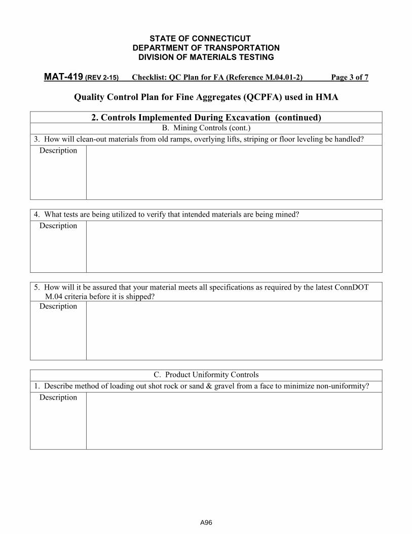
STATE OF CONNECTICUT DEPARTMENT OF TRANSPORTATION
DIVISION OF MATERIALS TESTING
MAT-419 (REV 2-15) Checklist: QC Plan for FA (Reference M.04.01-2) Page 3 of 7
Quality Control Plan for Fine Aggregates (QCPFA) used in HMA
2. Controls Implemented During Excavation (continued) B. Mining Controls (cont.)
3. How will clean-out materials from old ramps, overlying lifts, striping or floor leveling be handled?
Description
4. What tests are being utilized to verify that intended materials are being mined?
Description
5. How will it be assured that your material meets all specifications as required by the latest ConnDOT
M.04 criteria before it is shipped?
Description
C. Product Uniformity Controls
1. Describe method of loading out shot rock or sand & gravel from a face to minimize non-uniformity?
Description
A96
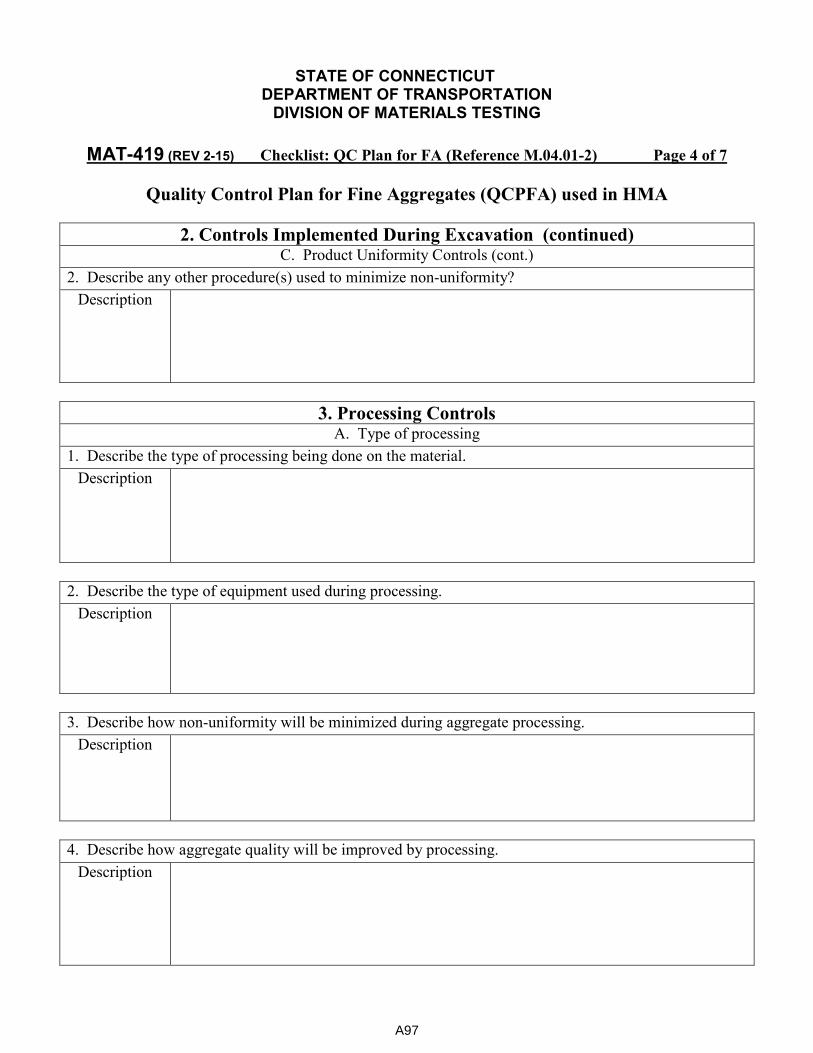
STATE OF CONNECTICUT DEPARTMENT OF TRANSPORTATION
DIVISION OF MATERIALS TESTING
MAT-419 (REV 2-15) Checklist: QC Plan for FA (Reference M.04.01-2) Page 4 of 7
Quality Control Plan for Fine Aggregates (QCPFA) used in HMA
2. Controls Implemented During Excavation (continued) C. Product Uniformity Controls (cont.)
2. Describe any other procedure(s) used to minimize non-uniformity?
Description
3. Processing Controls A. Type of processing
1. Describe the type of processing being done on the material.
Description
2. Describe the type of equipment used during processing.
Description
3. Describe how non-uniformity will be minimized during aggregate processing.
Description
4. Describe how aggregate quality will be improved by processing.
Description
A97
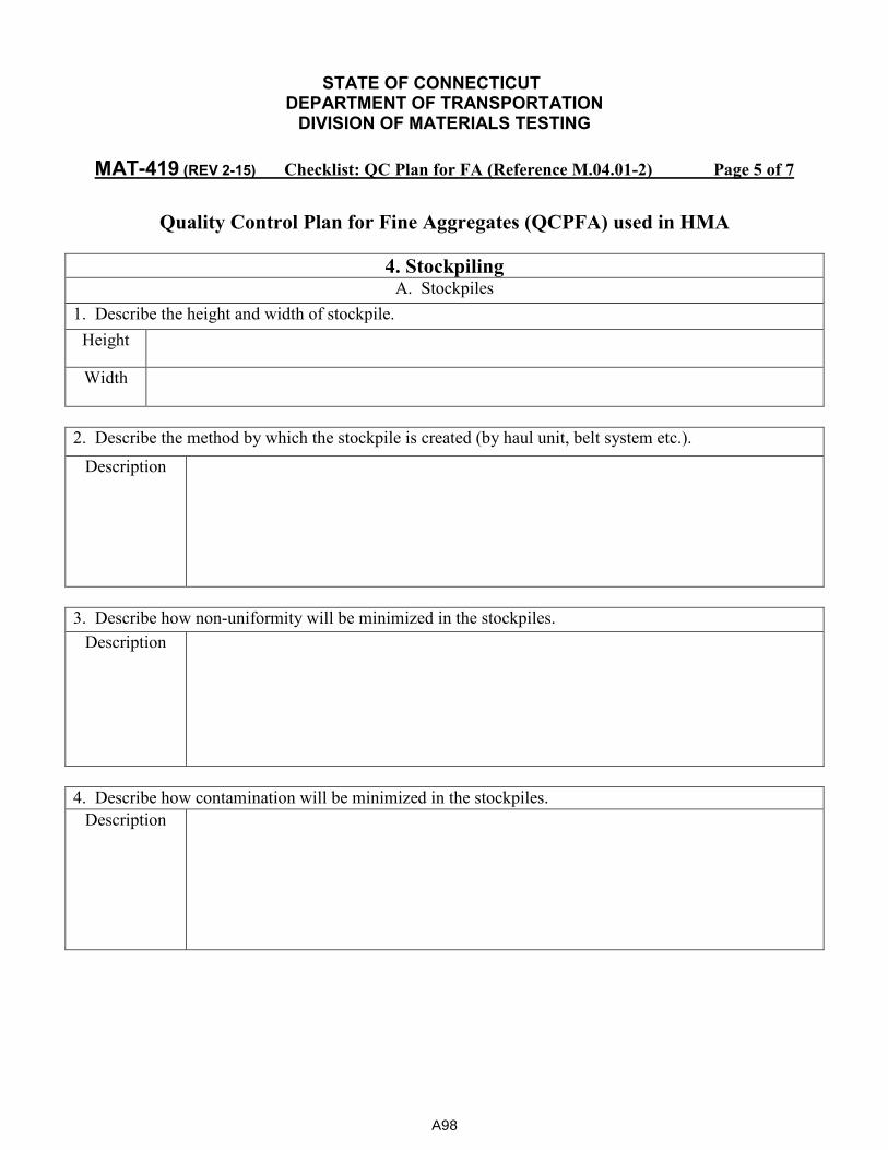
STATE OF CONNECTICUT DEPARTMENT OF TRANSPORTATION
DIVISION OF MATERIALS TESTING
MAT-419 (REV 2-15) Checklist: QC Plan for FA (Reference M.04.01-2) Page 5 of 7
Quality Control Plan for Fine Aggregates (QCPFA) used in HMA
4. Stockpiling A. Stockpiles
1. Describe the height and width of stockpile.
Height
Width
2. Describe the method by which the stockpile is created (by haul unit, belt system etc.).
Description
3. Describe how non-uniformity will be minimized in the stockpiles.
Description
4. Describe how contamination will be minimized in the stockpiles.
Description
A98

STATE OF CONNECTICUT DEPARTMENT OF TRANSPORTATION
DIVISION OF MATERIALS TESTING
MAT-419 (REV 2-15) Checklist: QC Plan for FA (Reference M.04.01-2) Page 6 of 7
Quality Control Plan for Fine Aggregates (QCPFA) used in HMA
4. Stockpiling (continued) A. Stockpiles (cont.)
5. Describe how the stockpiles will be monitored for non-uniformity and contamination.
(How will non-uniformity and contamination be visually monitored and by who?)
Description
Who will be
monitoring?
6. What physical tests will be employed to monitor quality of fine aggregate?
Description
7. What is the minimum testing frequency?
Description
8. Who will do the test?
Description
A99
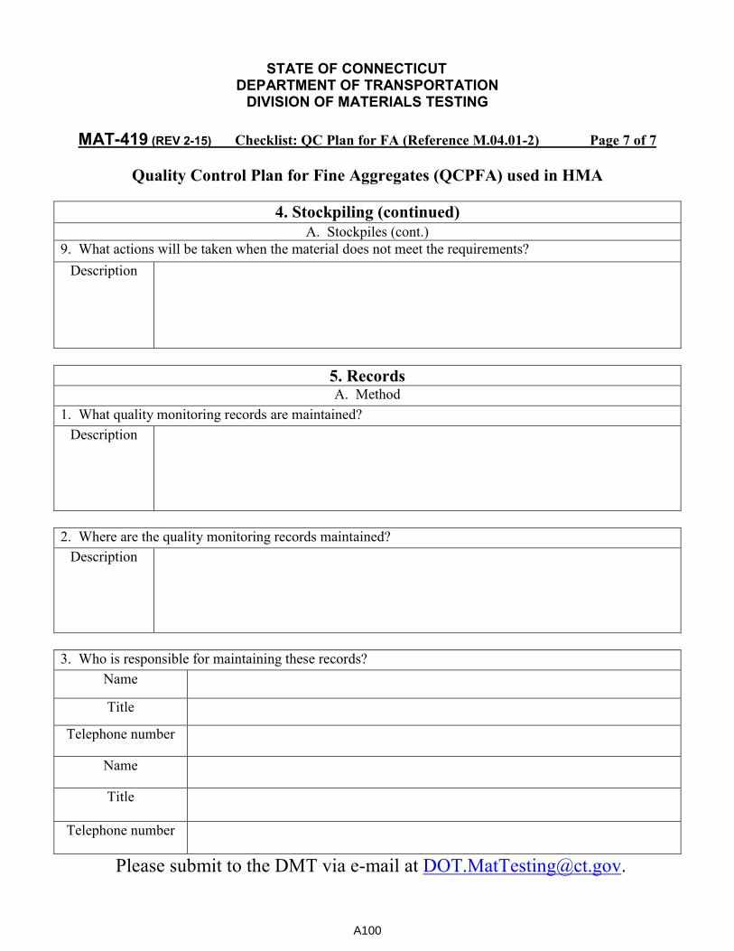
STATE OF CONNECTICUT DEPARTMENT OF TRANSPORTATION
DIVISION OF MATERIALS TESTING
MAT-419 (REV 2-15) Checklist: QC Plan for FA (Reference M.04.01-2) Page 7 of 7
Quality Control Plan for Fine Aggregates (QCPFA) used in HMA
4. Stockpiling (continued)
A. Stockpiles (cont.)
9. What actions will be taken when the material does not meet the requirements?
Description
5. Records A. Method
1. What quality monitoring records are maintained?
Description
2. Where are the quality monitoring records maintained?
Description
3. Who is responsible for maintaining these records?
Name
Title
Telephone number
Name
Title
Telephone number
Please submit to the DMT via e-mail at [email protected].
A100

State of Connecticut
Department of Transportation
Division of Materials Testing
Description Blend Percent
Asphalt Binder Grade
Antistrip Percentage
Warm Mix Technology
Nom. Size
Agg 1 Agg 2 Agg 3 Agg 4 Agg 5 Agg 6 Agg 7 Calc.
CA CA CA CA/RAP FA FA FA JMF
Description Comp.
Blend Percent Min % Max %
0.075 3.0 8.0
0.150
0.300 10.0 30.0
0.600 20.0 40.0
1.18
2.36 40.0 70.0
4.75 65.0 87.0
9.5 95.0 100.012.5 100.0 100.0
19.0
25.0
Production Virgin Pb
Total binder in RAP
Test Results WET
Gmm DRY
Gmb - Ndes User Notes:
Gmb - Nini -
Height-Ndes - Production Pb (w/ RAP) = The total production binder in the HMA.
Height-Ndes - Contractor JMF should reflect extracted asphalt and washed sieved analysis.
Height-Nini - List all the JMF Changes in the "JMF Changes" sheet.
% Gmm at Nini - Volumetric data for total asphalt content.
Gse - Complete the % passing per each specimen up to at least the 25.0mm sieve.
Va - Ndes - Add binder specific gravity data if it differs from 1.033.
Ignition Oven Corr. Factor
Remarks:
Mfg recomm compaction temp range
Contractor Data
White cells to be completed by the Contractor.
MIX TEMP
Accepted By Date
AC Range
Plant
Plant Type/Capacity
Date Submitted
Submitted By
Source of Supply
MIX #
CA-Aggregate 1
CA-Aggregate 2
CA-Aggregate 3
Source Location
Curb Mix
Specifications
Location
Size/Type of Aggregate
FA-Aggregate 7
Contractor
JMF
Control Points
Submitted
Source of Supply
or additive rate per total weight of mixadditive rate per weight of binderWater inject rate per weight of binder or
Total/Target AC
Mfg recomm compaction temp range
Mix TimesCOMPACTION TEMP
RAP AC
9.5mm L1
FA-Aggregate 6
Laboratory Temperature Ranges Production Temperature Ranges
CA/RAP-Aggregate 4
Mfg recommended mix temp range Mfg recommended mix temp range
6.5 - 9.0
Description
FA-Aggregate 5
A101
lauzonrg
Text Box
MAT - 429cm
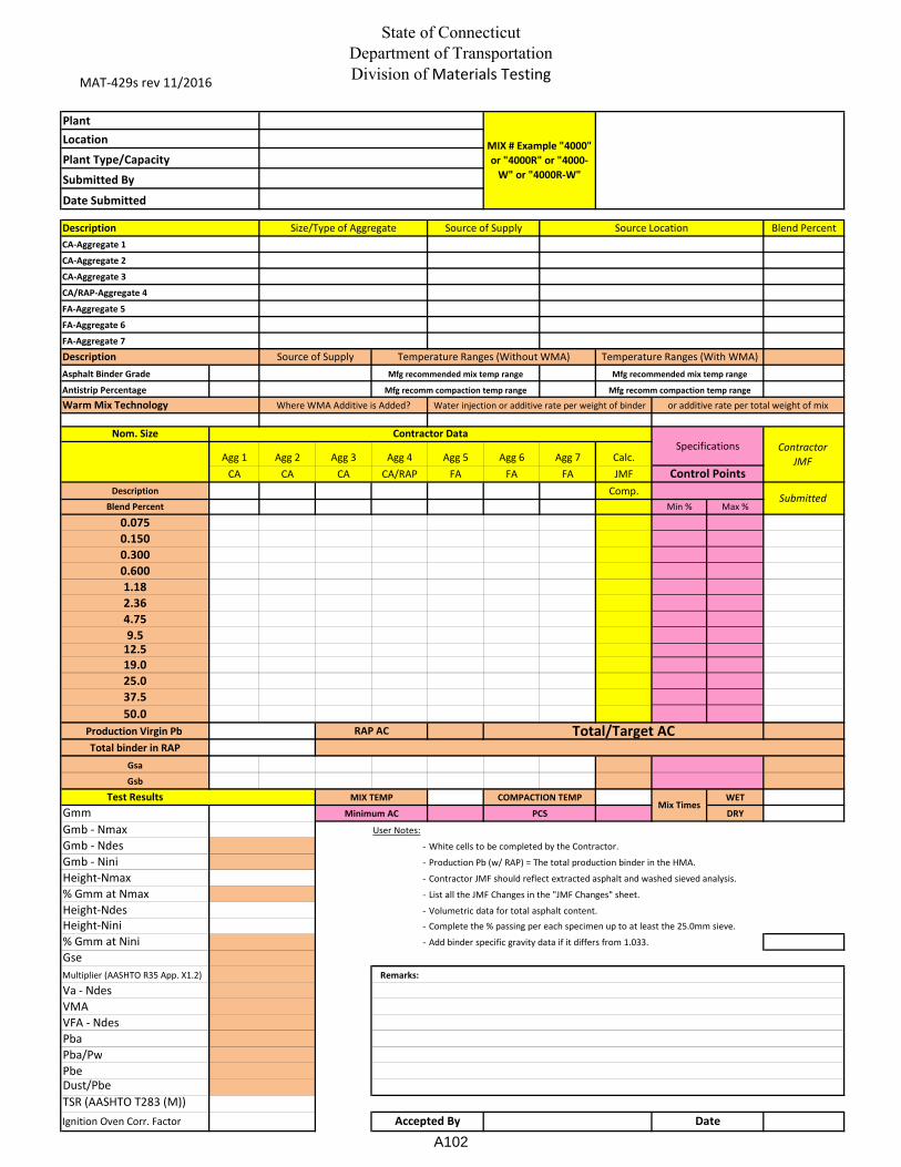
MAT-429s rev 11/2016
State of Connecticut
Department of Transportation
Division of Materials Testing
Description Blend Percent
Asphalt Binder Grade
Antistrip Percentage
Warm Mix Technology
Nom. Size
Agg 1 Agg 2 Agg 3 Agg 4 Agg 5 Agg 6 Agg 7 Calc.
CA CA CA CA/RAP FA FA FA JMF
Description Comp.
Blend Percent Min % Max %
0.075
0.150
0.300
0.600
1.18
2.36
4.75
9.512.5
19.0
25.0
37.5
50.0
Production Virgin Pb
Total binder in RAP
Gsa
Gsb
Test Results WET
Gmm DRY
Gmb - Nmax User Notes:
Gmb - Ndes -
Gmb - Nini - Production Pb (w/ RAP) = The total production binder in the HMA.
Height-Nmax - Contractor JMF should reflect extracted asphalt and washed sieved analysis.
% Gmm at Nmax - List all the JMF Changes in the "JMF Changes" sheet.
Height-Ndes - Volumetric data for total asphalt content.
Height-Nini - Complete the % passing per each specimen up to at least the 25.0mm sieve.
% Gmm at Nini - Add binder specific gravity data if it differs from 1.033.
Gse
Multiplier (AASHTO R35 App. X1.2) Remarks:
Va - Ndes
VMA
VFA - Ndes
Pba
Pba/Pw
Pbe
Dust/Pbe
TSR (AASHTO T283 (M))
Ignition Oven Corr. Factor
FA-Aggregate 6
Temperature Ranges (With WMA)
FA-Aggregate 5
CA/RAP-Aggregate 4
Water injection or additive rate per weight of binder
Description
COMPACTION TEMP
PCS
RAP AC
Specifications
or additive rate per total weight of mixWhere WMA Additive is Added?
Contractor
JMF
Control Points
Total/Target AC
Submitted
Mfg recomm compaction temp range
Mix Times
Location
Size/Type of Aggregate
FA-Aggregate 7
Source of Supply Temperature Ranges (Without WMA)
Source Location
CA-Aggregate 1
CA-Aggregate 2
CA-Aggregate 3
Plant
Plant Type/Capacity
Date Submitted
Submitted By
Source of Supply
MIX # Example "4000"
or "4000R" or "4000-
W" or "4000R-W"
Minimum AC
MIX TEMP
White cells to be completed by the Contractor.
Accepted By Date
Mfg recommended mix temp range Mfg recommended mix temp range
Mfg recomm compaction temp range
Contractor Data
A102

Form-429ut rev 02-15
State of Connecticut
Department of Transportation
Division of Materials Testing
Description Blend Percent
Asphalt Binder Grade
Antistrip Percentage
Warm Mix Technology
Nom. Size
Agg 1 Agg 2 Agg 3 Agg 4 Agg 5 Agg 6 Agg 7 Calc.
CA CA CA CA/RAP FA FA FA JMF
Description Comp.
Blend Percent Min % Max %
0.075 4.0 7.0
0.150 5.0 10.0
0.300 8.0 16.0
0.600 12.0 20.0
1.18 16.0 26.0
2.36 21.0 32.0
4.75 24.0 40.0
6.5 30.0 50.09.5 85.0 100.0
12.5 100.0 100.0
19.0
25.0
37.5
50.0
Production Virgin Pb 5.00Total binder in RAP
Gsa WET
Gsb DRY
4.8-5.4
Gmm User Notes:
Gse -
Multiplier (AASHTO R35 X1.2) - Production Pb (w/ RAP) = The total production binder in the HMA
Pba (%) - Contractor JMF should reflect extracted asphalt and washed sieved analysis
SA (m2/kg) - List all the JMF Changes in the "JMF Changes" sheet
Pbe (%) - In the table on the left, provide the HMA volumetric data for the Total AC= 5
Tf (µm) - Complete the % passing per each specimen up to at least the 25.0mm sieve
Draindown (%) - Add binder Specific Gravity data if it differs from 1.033
TSR (%)
Ignition Oven Corr Factor Remarks:
Description Laboratory Temperature Ranges Production Temperature Ranges
additive rate per weight of binderWater inject rate per weight of binder or or additive rate per total weight of mix
Mfg recommended mix temp range
Accepted By Date
Mfg recomm compaction temp range
Mfg recommended mix temp range
Mfg recomm compaction temp range
Total AC / JMF Pb Total
Source Location
Source of Supply
Plant
Location
Date Submitted
Submitted By
MIX #Plant Type/Capacity
CA-Aggregate 3
CA/RAP-Aggregate 4
FA-Aggregate 6
CA-Aggregate 1
CA-Aggregate 2
Ultra-Thin HMA
Type B
Source of Supply
FA-Aggregate 5
Size/Type of Aggregate
White cells to be completed by the contractor
FA-Aggregate 7
9.5mm
AC
5.00
Contractor
JMF
Contractor DataSpecifications
Mix Times
RAP AC
Control Points
Test Results
Submitted
A103
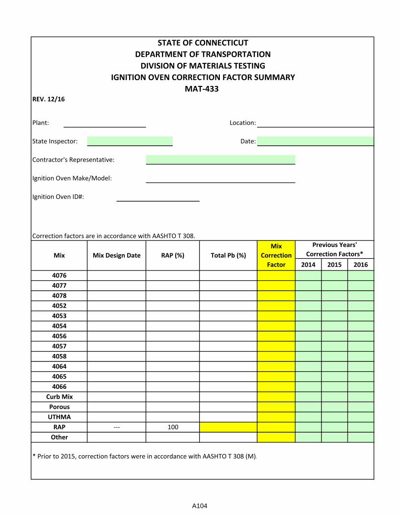
REV. 12/16
Plant: Location:
State Inspector: Date:
Contractor's Representative:
Ignition Oven Make/Model:
Ignition Oven ID#:
Correction factors are in accordance with AASHTO T 308.
2014 2015 2016
* Prior to 2015, correction factors were in accordance with AASHTO T 308 (M).
4065
4056
STATE OF CONNECTICUT
DEPARTMENT OF TRANSPORTATION
DIVISION OF MATERIALS TESTING
4066
RAP
4078
4053
4054
Other
4058
---
UTHMA
4077
100
4076
4052
Mix Mix Design Date
IGNITION OVEN CORRECTION FACTOR SUMMARY
MAT-433
RAP (%) Total Pb (%)
Mix
Correction
Factor
Previous Years'
Correction Factors*
4064
4057
Porous
Curb Mix
A104
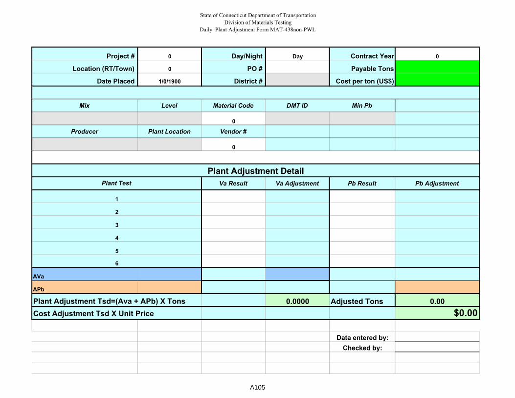
State of Connecticut Department of Transportation
Division of Materials Testing
Daily Plant Adjustment Form MAT-438non-PWL
Project # 0 Day/Night Day Contract Year 0
Location (RT/Town) 0 PO # Payable Tons
Date Placed 1/0/1900 District # Cost per ton (US$)
Mix Level Material Code DMT ID Min Pb
0
Producer Plant Location Vendor #
0
Va Result Va Adjustment Pb Result Pb Adjustment
AVa
APb
0.0000 Adjusted Tons 0.00
$0.00
Data entered by:
Checked by:
4
5
6
Plant Adjustment Tsd=(Ava + APb) X Tons
Cost Adjustment Tsd X Unit Price
Plant Adjustment Detail
Plant Test
1
2
3
A105

State of Connecticut Department of Transportation
Division of Materials Testing
Daily Plant Adjustment Form MAT-438PWL
Day/Night 0
PO #
District #
Mix Level DMT ID Vendor #
0
4 #VALUE!
SublotProduction
DateAV Pb VMA Lot Size
Production
Lot PWL
Adjustment1
2
3
4
0 0 0
5.2 #VALUE! #VALUE!
2.8 #VALUE! #VALUE!
PDl Checked by:
Material Code Producer Plant Location
0
PDu Data entered by:
LSL
Qu
Ql
Standard Deviation
Number of Results Plant Adjustment Tsd= PWL Adj X TonsUSL Cost Adjustment Tsd X Unit Price
Average
0
Targets
PWL (AV/Pb/VMA)PWL Adj
(AV/Pb/VMA)
PWL Lot Number 0 Cost per ton (US$)
Project # 0 Day Contract Year
Location (RT/Town) 0 Payable Tons
A106
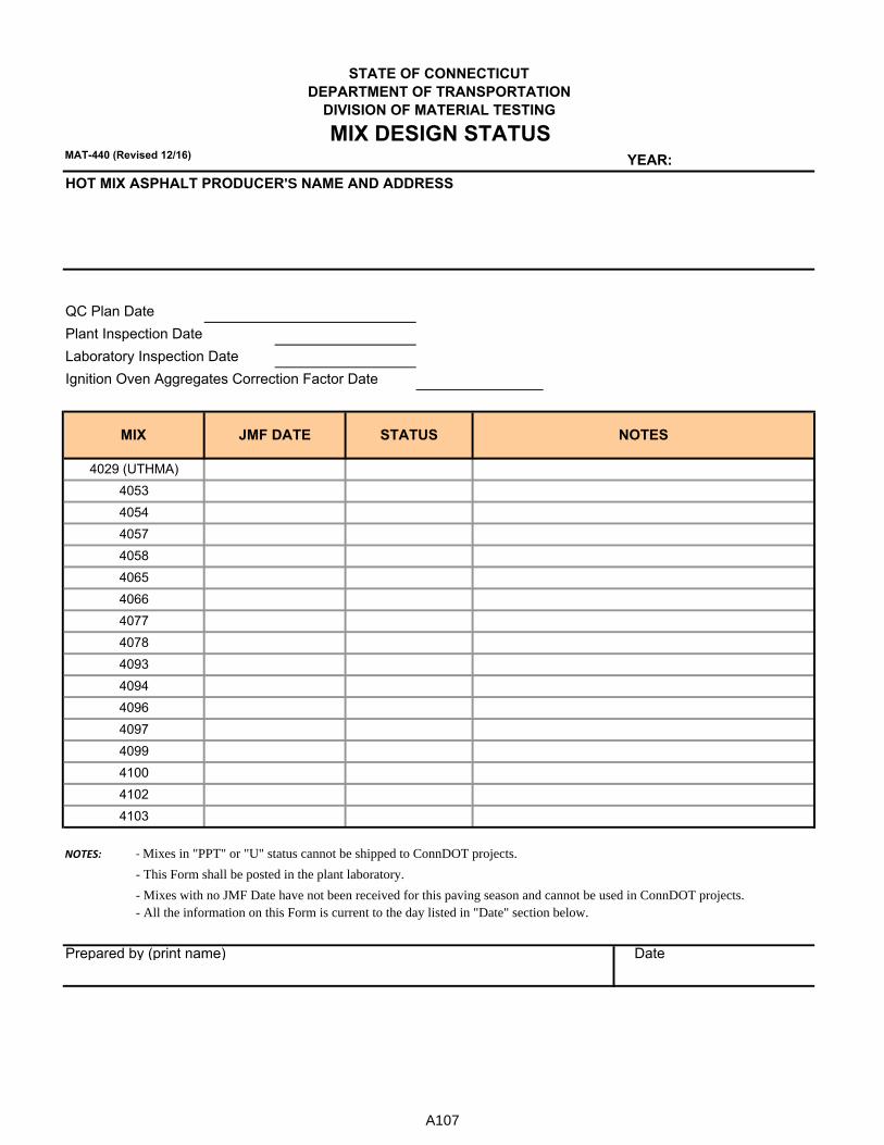
MAT-440 (Revised 12/16) YEAR:
HOT MIX ASPHALT PRODUCER'S NAME AND ADDRESS
QC Plan Date
Plant Inspection Date
Laboratory Inspection Date
Ignition Oven Aggregates Correction Factor Date
NOTES: - Mixes in "PPT" or "U" status cannot be shipped to ConnDOT projects.
- This Form shall be posted in the plant laboratory.
- Mixes with no JMF Date have not been received for this paving season and cannot be used in ConnDOT projects.- All the information on this Form is current to the day listed in "Date" section below.
Prepared by (print name) Date
4103
4078
4066
STATE OF CONNECTICUT
DEPARTMENT OF TRANSPORTATION
MIX STATUSJMF DATE
DIVISION OF MATERIAL TESTING
MIX DESIGN STATUS
4099
NOTES
4053
4077
4097
4100
4102
4029 (UTHMA)
4054
4057
4058
4065
4093
4094
4096
A107
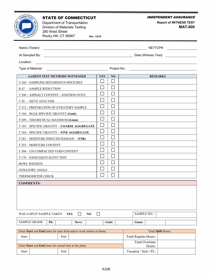
STATE OF CONNECTICUT INDEPENDENT ASSURANCE
Department of Transportation Report of WITNESS TEST
Division of Materials Testing MAT-600
280 West Street
Rocky Hill, CT 06067 Rev. 12/16
Name (Tester): NETTCP#: IA Sampled By: Date (Witness Test): Location: Type of Material: Project No.:
AASHTO TEST METHODS WITNESSED YES NO REMARKS
T 168 – SAMPLING BITUMINOUS MIXTURES
R 47 – SAMPLE REDUCTION
T 308 – ASPHALT CONTENT – IGNITION OVEN
T 30 – SIEVE ANALYSIS
T 312 – PREPARATION OF GYRATORY SAMPLE
T 166 – BULK SPECIFIC GRAVITY (Gmb)
T 209 – THEORETICAL MAXIMUM (Gmm)
T 185 – SPECIFIC GRAVITY – COARSE AGGREGATE
T 184 – SPECIFIC GRAVITY – FINE AGGREGATE
T 283 – MOISTURE INDUCED DAMAGE – (TSR)
T 255 – MOISTURE CONTENT
T 304 – UN-COMPACTED VOID CONTENT
T 176 – SAND EQUIVALENT TEST
BOWL WEIGHTS
GYRATORY ANGLE
THERMOMETER CHECK
COMMENTS:
WAS A SPLIT SAMPLE TAKEN YES NO SAMPLE NO.:
SAMPLE GRADE: Pb: Sieve: Gmb: Gmm:
Enter Start and End times for time from and to work station or home. Total Shift Hours
Start: End: Total Regular Hours:
Total Overtime
Hours:
Enter Start and End times for actual time at the plant.
Start: End: Vacation / Sick / PL:
A108

B1
Appendix B – Final Materials Certification A Final Materials Certificate (FMC) summarizes the results of acceptance testing of the material used on each FHWA-funded project and select state-funded projects. Materials used on these projects that require acceptance testing must be sampled and tested in accordance with the “Schedule of Minimum Requirements for Acceptance Testing,” Chapter 8 of this manual. It is imperative that the represented quantity of each material with a sampling frequency of “one per quantity” or “one per x units” accumulate to or exceed the total quantity of that material used on the project. For some materials the minimum schedule does not indicate a testing frequency. In this instance, a single sample will be adequate to represent that material incorporated into the project. In addition, the Division of Materials Testing (DMT) documents the process of materials testing on the project site by checking the sampling and testing procedures performed by inspection personnel in accordance with the “Schedule of Minimum Requirements for Assurance Testing,” Chapter 9 of this manual. Testing equipment is also checked to ensure that the test results are valid. Discrepancies in this testing are investigated and rectified immediately. The DMT reports the results of this testing to the Federal Highway Administration on an annual basis. To initiate the development of a FMC, a request from the appropriate District office staff for a FMC is sent to the DMT. Following a review of project records, DMT staff issue a memorandum to the project personnel entitled “Test Coverage Required for FINAL CERTIFICATION” that lists all testing deficiencies and rejected materials not previously documented. It is the responsibility of the Transportation Supervising Engineers of each DMT section to identify material that did not meet the project specifications, was not documented correctly, and was permanently incorporated into the project. This is accomplished through the issuance of a FMC listing exceptions to the specifications. When all materials used on the project are sampled and found to meet the specification or are documented properly, the DMT issues a FMC without exceptions. When tested material does not meet specification, a MAT-103 “Report of Rejected Material” form is used to document how the deficiency was addressed. This form must be completed for any rejected material samples and must include the signatures of appropriate Project and District personnel acknowledging the rejection. Section 1 of the Mat-103 form under the heading “Action Taken” describes the physical action taken to retest or replace the material. This addresses when rejected materials were removed and replaced with acceptable material or were resampled and found acceptable. The Sample ID of the acceptable re-test is required on this form. If physical action was not taken, Section 2 of the MAT-103 must be completed. Section 2 of the Mat-103 form under the heading “Acceptance of Rejected Material without Action” documents the acceptance of noncompliant materials or minor quantities
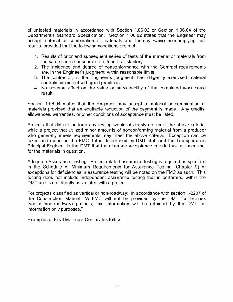
B2
of untested materials in accordance with Section 1.06.02 or Section 1.06.04 of the Department’s Standard Specification. Section 1.06.02 states that the Engineer may accept material or combination of materials and thereby waive noncomplying test results, provided that the following conditions are met:
1. Results of prior and subsequent series of tests of the material or materials from the same source or sources are found satisfactory.
2. The incidence and degree of nonconformance with the Contract requirements are, in the Engineer’s judgment, within reasonable limits.
3. The contractor, in the Engineer’s judgment, had diligently exercised material controls consistent with good practices.
4. No adverse affect on the value or serviceability of the completed work could result.
Section 1.06.04 states that the Engineer may accept a material or combination of materials provided that an equitable reduction of the payment is made. Any credits, allowances, warranties, or other conditions of acceptance must be listed. Projects that did not perform any testing would obviously not meet the above criteria, while a project that utilized minor amounts of nonconforming material from a producer who generally meets requirements may meet the above criteria. Exception can be taken and noted on the FMC if it is determined by DMT staff and the Transportation Principal Engineer in the DMT that the alternate acceptance criteria has not been met for the materials in question. Adequate Assurance Testing: Project related assurance testing is required as specified in the Schedule of Minimum Requirements for Assurance Testing (Chapter 9) or exceptions for deficiencies in assurance testing will be noted on the FMC as such. This testing does not include independent assurance testing that is performed within the DMT and is not directly associated with a project. For projects classified as vertical or non-roadway: In accordance with section 1-2207 of the Construction Manual, “A FMC will not be provided by the DMT for facilities (vertical/non-roadway) projects; this information will be retained by the DMT for information only purposes.” Examples of Final Materials Certificates follow.
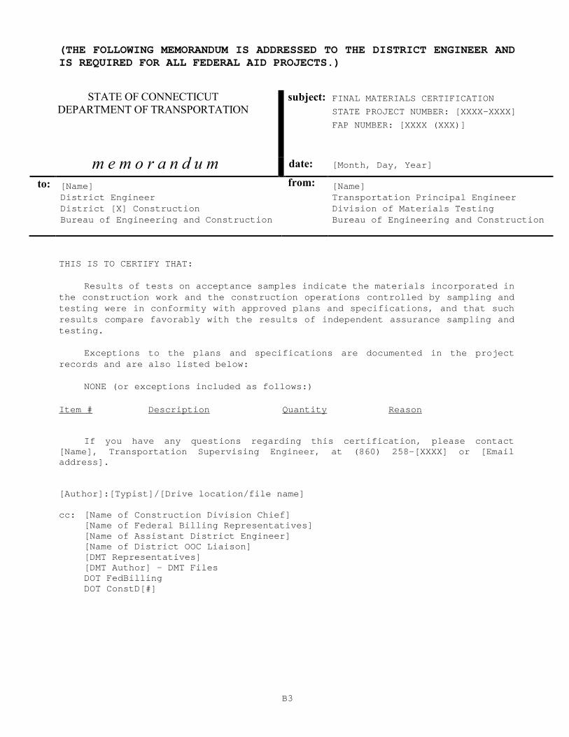
B3
(THE FOLLOWING MEMORANDUM IS ADDRESSED TO THE DISTRICT ENGINEER AND IS REQUIRED FOR ALL FEDERAL AID PROJECTS.)
STATE OF CONNECTICUT DEPARTMENT OF TRANSPORTATION
subject: FINAL MATERIALS CERTIFICATION
STATE PROJECT NUMBER: [XXXX-XXXX]
FAP NUMBER: [XXXX (XXX)]
m e m o r a n d u m date: [Month, Day, Year]
to: [Name] from: [Name] District Engineer Transportation Principal Engineer District [X] Construction Division of Materials Testing Bureau of Engineering and Construction Bureau of Engineering and Construction
THIS IS TO CERTIFY THAT:
Results of tests on acceptance samples indicate th e materials incorporated in the construction work and the construction operatio ns controlled by sampling and testing were in conformity with approved plans and specifications, and that such results compare favorably with the results of indep endent assurance sampling and testing.
Exceptions to the plans and specifications are doc umented in the project records and are also listed below:
NONE (or exceptions included as follows:)
Item # Description Quantity Reason
If you have any questions regarding this certifica tion, please contact [Name], Transportation Supervising Engineer, at (86 0) 258-[XXXX] or [Email address]. [Author]:[Typist]/[Drive location/file name] cc: [Name of Construction Division Chief] [Name of Federal Billing Representatives] [Name of Assistant District Engineer] [Name of District OOC Liaison] [DMT Representatives] [DMT Author] – DMT Files DOT FedBilling DOT ConstD[#]
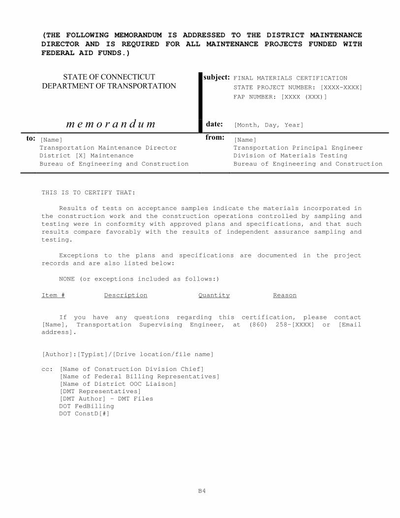
B4
(THE FOLLOWING MEMORANDUM IS ADDRESSED TO THE DISTRICT MAINTENANCE DIRECTOR AND IS REQUIRED FOR ALL MAINTENANCE PROJECTS FUNDED WITH FEDERAL AID FUNDS.)
STATE OF CONNECTICUT DEPARTMENT OF TRANSPORTATION
subject: FINAL MATERIALS CERTIFICATION
STATE PROJECT NUMBER: [XXXX-XXXX]
FAP NUMBER: [XXXX (XXX)]
m e m o r a n d u m date: [Month, Day, Year]
to: [Name] from: [Name] Transportation Maintenance Director Transportation Principal Engineer District [X] Maintenance Division of Materials Testing Bureau of Engineering and Construction Bureau of Engineering and Construction
THIS IS TO CERTIFY THAT:
Results of tests on acceptance samples indicate th e materials incorporated in the construction work and the construction operatio ns controlled by sampling and testing were in conformity with approved plans and specifications, and that such results compare favorably with the results of indep endent assurance sampling and testing.
Exceptions to the plans and specifications are doc umented in the project records and are also listed below:
NONE (or exceptions included as follows:)
Item # Description Quantity Reason
If you have any questions regarding this certifica tion, please contact [Name], Transportation Supervising Engineer, at (86 0) 258-[XXXX] or [Email address]. [Author]:[Typist]/[Drive location/file name] cc: [Name of Construction Division Chief] [Name of Federal Billing Representatives] [Name of District OOC Liaison] [DMT Representatives] [DMT Author] – DMT Files DOT FedBilling DOT ConstD[#]

FABRICATION INSPECTION
C1
APPENDIX C
SCOPE OF WORK FABRICATION INSPECTION For third-party testing agency
As determined by the Connecticut Department of Transportation’s (Department) Division Chief, the testing agency shall provide qualified inspection and testing personnel to perform inspections, sampling, and testing of materials in the following areas:
• General Requirements
• Steel Fabrication - Scope
• Structural Steel Inspection - General
• Coatings Process Inspection
• Precast, Prestressed and Post- Tensioned Concrete Inspection All inspections, sampling, and testing are to be done in accordance with applicable standards including, but not limited to, those described by the American Welding Society (AWS), National Association of Corrosion Engineers (NACE), American Association of State Highway Transportation Officials (AASHTO), and the American Society of Testing Materials (ASTM). Personnel performing the inspection, sampling, or testing of specific materials may require certification that is administered by agencies such as the New England Transportation Technician Certification Program (NETTCP), American Concrete Institute (ACI), and others. The purpose of this inspection, sampling, or testing is to assure conformance of the material to project specifications. As such, the Quality Assurance (QA) inspector may visually inspect, witness, sample, or test material during all phases of manufacture/fabrication/production. The primary function of the QA inspector is to assure the Engineer that the fabricator/producer is exercising adequate quality control during the entire fabrication/production process.
General Requirements
The testing agency shall:
1. Assume responsibility for the assigned inspection, sampling, or testing of materials as of the date stipulated by the Department in the formal notice to the testing agency to proceed with the work. This includes any partially completed work performed by the Department’s former testing agency under the “Contract for Inspection, Sampling and Testing of Materials” concluded February 14, 2016.
FABRICATION INSPECTION
C2
2. Make no decisions and offer no advice or opinion to a proposed action
by the manufacturer/fabricator/producer/contractor without first consulting with the Engineer. The Engineer is defined as the Division Chief or his duly authorized representative.
3. Provide all equipment required for the safe and comprehensive
execution of the work including personal safety equipment such as clothing, hard hats, safety glasses, shoes, and gloves. This may also include appropriate means of transportation for some job classifications. All such equipment may be subject to the approval of the Engineer.
4. Adhere to the Travel Expense Guidelines dated April 19, 2016 for the
purpose of determining travel expenses and work locations. The Inspector shall:
1. Be certified in the applicable field and have a thorough knowledge of the State of Connecticut - Department of Transportation - Standard Specifications for Roads, Bridges and Incidental Construction (Form 816 as supplemented), and project specifications, including approved shop drawings.
Specific information on scope of work, personnel, and reporting requirements for each area are provided in the following pages. Steel Fabrication - Scope The testing agency shall submit to the Department of Transportation, Division of Materials Testing, 280 West Street, Rocky Hill, CT 06067, three copies of daily reports on a weekly basis, or as directed, for each Department project where inspection services were performed indicating the status of each member in fabrication and the shipping status of each completed member. Report cover sheets and the body of the reports must be generated with a word processing computer application and output on 8.5” X 11” white paper. Handwritten reports will not be accepted. The reports shall include daily notes of the testing agency’s plant inspector and any nondestructive testing reports and shipping documents that were obtained during the day. These reports shall further include a daily summary of the number of hours worked. Weekly reports shall be due at the Department of Transportation’s Division of Materials Testing (DMT) no later than seven days after the close of the period covered by such reports. The final weekly report submitted for a single project shall include all certified mill test reports documenting all steel used in the project work.
FABRICATION INSPECTION
C3
Due to their critical function as load-bearing units of bridges and structures, structural steel members must be constructed in strict conformance with the specifications. To assure this conformance, the DMT assigns a QA inspector to the manufacturing/fabrication plant to inspect, in detail, all phases of manufacture/fabrication. The primary function of the QA inspector is to assure the Engineer that the fabricator is exercising adequate quality control during the entire fabrication process. Should the inspector discover deficiencies or witness a lack of quality control, it is imperative that the Engineer be notified immediately so that corrective action can be initiated. These specifications are not to be considered as covering every aspect of the testing agency’s responsibilities, and they shall in no way relieve the testing agency of the responsibility for the inspection of all requirements of the plans, specifications, and special provisions that are pertinent to the work. Structural Steel Inspection - General The inspector shall:
1. Commence inspection with the beginning of fabrication and continue throughout the entire fabrication process, or as directed by the Engineer.
2. Throughout the fabrication, document information on standardized
forms provided by the Engineer or on an acceptable substitution to the Engineer. All such documentation shall be neat and legible to the satisfaction of the Engineer.
3. Confirm that the proper approval has been granted for all shop
drawings used during fabrication/manufacture. This should be accomplished before fabrication; however, it may be done during or after fabrication. Should the fabricator decide to commence, continue, or deliver work without proper approval; the inspector is required to immediately notify the fabricator’s Quality Control (QC) Manager that the fabricator is proceeding at his own risk, and notify the Engineer that work began, is ongoing, or is being shipped without approved drawings. Inspector must note names, times, and summary of the discussion in his daily report.
4. Be cognizant of the conditions of fabrication including the time of
delivery, desired order of shipment, and any special features in connection with delivery.
5. Obtain the records of the chemical and physical tests of the heat
numbers of material from the mill. Review mill test reports for conformance to specifications and report status to the Engineer through daily reports.

FABRICATION INSPECTION
C4
6. Compare heat marks with those on the mill test reports. Should there
be any doubt about the identity of correctness of the metal, samples of the metal may be taken and tested by the fabricator to ascertain conformance with the appropriate specifications.
7. See that material is properly identified throughout the entire fabrication
process.
8. Conduct a surface inspection of a sample of incoming metals with attention to defects such as piping, cracks, laminations, buckles and kinks.
9. Observe that material not immediately used is properly stored and
identified.
10. Ensure that no material from shop stock is used without approval or without properly documented test reports. Pitted or corroded material shall not be used.
11. Document the position of heat numbers in main members by means of
diagrams showing member elevations and associated heat numbers.
12. Check a sample of cuts for neatness and trueness, and ensure that the proper method of cutting is used.
13. Inspect a sample of templates for accuracy.
14. Check a sample of splices, joints, and connections in accordance with
appropriate specifications.
15. Check the fit and positioning of a sample of shop assemblies, and ensure that members are clearly match-marked when members that are to be field-spliced are given a shop laydown assembly.
16. Be present when material is being cambered or straightened by the
application of heat to ensure use of proper procedures and temperature requirements. Confirm that only approved methods are being utilized.
17. Inspect a sample of completed work for general finish and
workmanship. Check a sample of finished members for dimensions, proper section, connection locations, detailing and other related features. Measure and record on approved forms the overall length, length center-to-center of bearings, and camber of a sample of main members.
FABRICATION INSPECTION
C5
18. Check that surfaces of “weathering” steel and surface areas to receive
protective coatings are properly prepared and that coatings are applied in accordance with specifications. The coating dates of all material shall be recorded in the daily report.
19. Ascertain that all welders, welding operators, and tackers have been
properly qualified and that welding procedures have been properly followed. Copies of welder certifications and approved welding procedures shall be incorporated into the project records. Actual welding should be inspected regularly to ensure that the minimum temperature requirements for welding are being maintained, that the specified joint-welding procedures are being followed, and that the required preheat, interpass and postheat temperatures are being utilized.
20. Witness all nondestructive testing of welds and sign all reports of such
testing. Ultrasonic inspection shall be witnessed and the interpretation of the results verified by the testing agency personnel, who shall be qualified NDT Level II or better in accordance with requirements of the American Society for Nondestructive Testing’s Recommended Practice Number SNT-TC-1A and Supplement C, Ultrasonic Testing Method.
21. Check to ensure use of proper electrodes, electrode-flux combination,
or grade of weld metal for the steel specified. Review materials certification for electrodes or electrode-flux combinations. Regularly inspect storage conditions and care of electrodes and flux for conformance to specifications. Check welding equipment for proper operation and proper calibration.
22. Perform visual inspection of a sample of completed welds and the
base metals for cracks, notches, undercutting, and other defects.
23. Check a sample of the finished welds for proper profile and cross-section.
24. Prior to shipment of the material, ensure that the fabricator’s
QC representative has inspected the members and reviewed the shipping documents for completeness. Determining the acceptability of each piece prior to shipping is the sole responsibility of the fabricator. The testing agency shall ensure that members are marked in such a manner as to enable the Department’s field representative to correlate shop inspection reports and shipping reports with the appropriate members.
25. Report and record all defects or problems observed, as well as all
corresponding corrective action taken within their daily reports submitted to the Department.
FABRICATION INSPECTION
C6
Coatings Process Inspection The NACE coating inspector shall fully complete a paint inspection checklist for all coated materials, take necessary samples of protective coatings for testing as directed by the Department’s DMT, and permit only approved material to be used. The NACE inspector shall be present at the fabrication/coating shop during all cleaning and coating operations. The daily coating activity shall be recorded in the latest edition of the NACE Coating Inspector’s log book and shall commence prior to the structural steel surface preparation. The testing agency shall be responsible for the purchase of the log books and shall provide them to each NACE inspector. At the time of material shipment from the fabricator’s plant, the NACE inspector shall stamp the front page of each inspector’s log book used during the coating operation. The stamped book shall indicate the inspector’s NACE certification number, expiration date, printed name of the inspector, and shall be signed by the inspector. The log book(s) shall then be furnished to the Senior Fabrication Inspector to be included with the submission of the weekly reports. Precast, Prestressed and Post-Tensioned Concrete Inspection Due to their critical function as load-bearing units of bridges and structures, precast, prestressed, and post-tensioned concrete members must be constructed in strict conformance with the specifications. To assure this conformance, the DMT assigns a QA inspector to the manufacturing/fabrication plant to inspect, in detail, all phases of manufacture/fabrication. The primary function of the QA inspector is to assure the Engineer that the fabricator is exercising adequate quality control during the entire fabrication process. Should the inspector discover deficiencies or witness a lack of quality control, it is imperative that the Engineer be notified immediately so that corrective action can be initiated. The inspector shall perform the following: Sampling
The following component materials shall be sampled for testing in accordance with standard Department procedures and frequencies listed below:
1. Portland cement: Shall be from a qualified source. Each load shall be
accepted by certification. Samples shall be taken as directed by the Engineer.
2. Aggregate: Samples from bins or stockpiles each month for each source
of supply, or as directed by the Engineer.
3. Admixtures: Only qualified admixtures are to be used. Samples are to be taken as directed by the Engineer.
FABRICATION INSPECTION
C7
4. Prestressing steel strand: Sample each reel or coil in accordance with
Standard Specifications, Article M.14.01-2.
5. Post-tensioning tendons and anchorages: Sample as per Special Provisions.
6. Reinforcing steel: From each source, a 5-foot (1.5 m) sample of each size
for every 200 tons (181.4 metric tons), with a minimum of one sample of each size from each source per project.
Inspection of Plant Facilities and Manufacturing Procedures
The plant facilities shall be inspected annually or as directed by the Engineer. A form provided by the Department shall be utilized as a guide to plant facilities inspection. As a minimum, the following shall be inspected:
1. Storage and handling of materials.
2. Batching, mixing, transportation and placement of concrete.
3. Curing method and apparatus (i.e., steam, radiant heat or other approved
method) including provision for recording time and temperature data during the curing cycle.
4. Concrete testing equipment (i.e., compression-testing machine - should
be calibrated every 12 months, pressure-type air meters, cylinder molds, slump cones, and unit weight apparatus) and facilities for moist-curing test cylinders in accordance with ASTM C 192.
5. Equipment and procedure for consolidation of concrete.
6. Construction and capacity of casting beds.
7. Dimensions, condition, and construction of forms.
8. Method and equipment for applying prestressing or post-tensioning
forces.
9. Method and equipment for measuring prestressing or post-tensioning forces and the procedure for measuring elongation of strands or tendons.
10. Accuracy and calibration data of pressure gauges. (Gauges shall be
calibrated at intervals not to exceed 6 months)

FABRICATION INSPECTION
C8
Inspection of Casting Bed
1. Check cleanliness, level, and alignment of form liner. 2. Check position of bulkheads for proper length of units and skewed or
sloped ends, when applicable.
3. Inspect stringing of prestressing strands to ensure correct number and position of strands and location of “hold-downs.”
4. For a sample of strands: inspect tension, measure elongation, and check
gauge reading for proper force application. Force measurement of elongation and gauge reading shall check each other and the theoretical value shall be within 5 percent.
5. Witness retensioning at the non-jacking end of deflected strands and
straight strands to verify application of the required prestressing force in accordance with the Standard Specifications, Article 5.14.03.
6. Inspect installation of a sample of post-tensioning tendons and
anchorages, when applicable.
7. Check size, type, and location of a sample of reinforcing steel, hardware, and miscellaneous steel when placed in forms.
8. Inspect condition and alignment of a sample of side forms.
9. Check proper bracing and anchorage of casting bed and end anchorages.
Inspection of Concrete Operations
1. Inspect a sample of concrete delivered to forms for homogeneity and uniformity of successive batches.
2. Spot-check batching and mixing of concrete to assure that approved mix
design and procedures are being used.
3. Witness/monitor sampling of concrete for quality control testing.
4. Witness slump, air tests, concrete temperature, and unit weight for conformance to specifications and accept or deem unacceptable on the basis of results.
5. Inspect placement, consolidation and finishing of concrete for
conformance to specifications and accepted concrete practices.
FABRICATION INSPECTION
C9
6. For deck units, inspect internal void forms for material, size, and proper
installation.
7. Check identification marker for required data and placement in unit.
8. Ensure that approved curing method is used and applied at proper time. If steam or radiant heat is used, ensure that required preset period is observed.
Inspection of Fabricated Units
1. Inspect a sample of units to determine if they were cured uniformly. Review the time/temperature record of curing cycle for specification compliance.
2. Witness testing of cylinders for required concrete strength prior to
detensioning or removal of forms.
3. Verify dimensions, details, surface finish, and freedom from defects of a sample of finished units.
4. Verify proper marking and identification of units.
5. Witness application of protective compound to surfaces of precast catch
basin and drop inlet tops, which will be exposed when in service.
6. Catch basin, drop inlets, manhole riser sections, bases, and appurtenances that exhibit the following may be recommended for rejection:
6.1 Fractures or cracks passing through the wall, except for a single end
crack that does not exceed the depth of the joint. 6.2 Defects that indicate imperfect proportioning, mixing, or molding. 6.3 Surface defects indicating honeycombed or open texture. 6.4 Any continuous crack having a surface width of 0.01 in. (0.3mm) or
more and extending for a length of 1.0 ft. (300mm) or more, regardless of position in the section wall.
6.5 Damaged or cracked ends where such damage would prevent
making a satisfactory joint. Reporting – As directed by a Department representative, the inspector will document test results on forms provided by the Department.

MATERIAL TESTING INSPECTION
C10
SCOPE OF WORK
MATERIAL TESTING INSPECTION For Consultant third-party Testing Agency (Testing Agency)
As determined by the Connecticut Department of Transportation’s (Department) Division Chief of Construction Services and Materials Testing (Division Chief), the Testing Agency shall provide qualified inspection and testing personnel to perform inspections, sampling, and testing of materials in the following areas:
• General Requirements
• Precast, Prestressed and Post-Tensioned Concrete Inspection
• HMA Plant Inspection
• Sampling Materials (i.e., Hot Mix Asphalt [HMA], aggregates) on Project Sites or Sources
• Testing In-Place Materials (HMA, aggregates) on Project Sites
• Testing Material Samples at Department Material Testing Facilities
• Inputting Test Results, Processing Request for Test (MAT-100) Forms, and Filing Documentation
All inspections, sampling, and testing are to be done in accordance with applicable standards including, but not limited to, those described by the American Welding Society (AWS), National Association of Corrosion Engineers (NACE), American Association of State Highway Transportation Officials (AASHTO), and the American Society of Testing Materials (ASTM). Personnel performing the inspection, sampling, or testing of specific materials shall require certification that is administered by agencies such as the New England Transportation Technician Certification Program (NETTCP), American Concrete Institute (ACI), and others. The purpose of this inspection, sampling, or testing is to assure conformance of the material to project specifications. The primary function of the Quality Assurance (QA) Inspector is to assure the Engineer that the fabricator/producer is exercising adequate quality control during the entire fabrication/production process. The Engineer is defined as the Division Chief or his duly authorized representative. As such, the QA Inspector shall visually inspect, witness, sample, or test material during all phases of manufacture/fabrication/production.
General Requirements
The Testing Agency shall:
1. Assume responsibility for the assigned inspection, sampling, or testing of materials as of the date stipulated by the Department in the formal notice to the Testing Agency to proceed with the work. This includes any partially completed work performed by the Department’s former Testing Agency under the “Task Order Fabrication/Materials Inspection Services” contract that concluded February 14, 2016.

MATERIAL TESTING INSPECTION
C11
2. Make no decisions and offer no advice or opinion to a proposed action
by the manufacturer/fabricator/producer/contractor without first consulting with the Engineer.
3. Provide all equipment required for the safe and comprehensive
execution of the work including personal safety equipment such as clothing, hard hats, safety glasses, shoes, and gloves. This will also include appropriate means of transportation for some job classifications. All such equipment is subject to the approval of the Engineer.
4. Adhere to the Travel Expense Guidelines dated April 19, 2016 for the
purpose of determining travel expenses and work locations. The QA Inspector shall:
1. Be certified in the applicable field and have a thorough knowledge of the State of Connecticut - Department of Transportation - Standard Specifications for Roads, Bridges and Incidental Construction (Form 816 as supplemented), and project specifications, including approved shop drawings.
Specific information on scope of work, personnel, and reporting requirements for each area are provided in the following pages. Precast, Prestressed and Post-Tensioned Concrete Inspection Due to their critical function as load-bearing units of bridges and structures, precast, prestressed, and post-tensioned concrete members must be constructed in strict conformance with the specifications. To assure this conformance, the DMT assigns a QA Inspector to the manufacturing/fabrication plant to inspect, in detail, all phases of manufacture/fabrication. The primary function of the QA Inspector is to assure the Engineer that the fabricator is exercising adequate quality control during the entire fabrication process. Should the QA Inspector discover deficiencies or witness a lack of quality control, it is imperative that the Engineer be notified immediately so that corrective action can be initiated. The QA Inspector shall perform the following: Sampling
The following component materials shall be sampled for testing in accordance with standard Department procedures and frequencies listed below:
1. Portland cement: Shall be from a qualified source. Each load shall be
accepted by certification. Samples shall be taken as directed by the Engineer.

MATERIAL TESTING INSPECTION
C12
2. Aggregate: Samples from bins or stockpiles each month for each source
of supply, or as directed by the Engineer.
3. Admixtures: Only qualified admixtures are to be used. Samples are to be taken as directed by the Engineer.
4. Prestressing steel strand: Sample each reel or coil in accordance with
Standard Specifications, Article M.14.01-2.
5. Post-tensioning tendons and anchorages: Sample as per Special Provisions.
6. Reinforcing steel: From each source, a 5-foot (1.5 m) sample of each size
for every 200 tons (181.4 metric tons), with a minimum of one sample of each size from each source per project.
Inspection of Plant Facilities and Manufacturing Procedures
The plant facilities shall be inspected annually or as directed by the Engineer. A form provided by the Department shall be utilized as a guide to plant facilities inspection. As a minimum, the following shall be inspected:
1. Storage and handling of materials.
2. Batching, mixing, transportation and placement of concrete.
3. Curing method and apparatus (i.e., steam, radiant heat or other approved
method) including provision for recording time and temperature data during the curing cycle.
4. Concrete testing equipment (i.e., compression-testing machine - should
be calibrated every 12 months, pressure-type air meters, cylinder molds, slump cones, and unit weight apparatus) and facilities for moist-curing test cylinders in accordance with ASTM C 192.
5. Equipment and procedure for consolidation of concrete.
6. Construction and capacity of casting beds.
7. Dimensions, condition, and construction of forms.
8. Method and equipment for applying prestressing or post-tensioning
forces.
9. Method and equipment for measuring prestressing or post-tensioning forces and the procedure for measuring elongation of strands or tendons.
10. Accuracy and calibration data of pressure gauges. (Gauges shall be
calibrated at intervals not to exceed 6 months)

MATERIAL TESTING INSPECTION
C13
Inspection of Casting Bed
1. Check cleanliness, level, and alignment of form liner. 2. Check position of bulkheads for proper length of units and skewed or
sloped ends, when applicable.
3. Inspect stringing of prestressing strands to ensure correct number and position of strands and location of “hold-downs.”
4. For a sample of strands: inspect tension, measure elongation, and check
gauge reading for proper force application. Force measurement of elongation and gauge reading shall check each other and the theoretical value shall be within 5 percent.
5. Witness retensioning at the non-jacking end of deflected strands and
straight strands to verify application of the required prestressing force in accordance with the Standard Specifications, Article 5.14.03.
6. Inspect installation of a sample of post-tensioning tendons and
anchorages, when applicable.
7. Check size, type, and location of a sample of reinforcing steel, hardware, and miscellaneous steel when placed in forms.
8. Inspect condition and alignment of a sample of side forms.
9. Check proper bracing and anchorage of casting bed and end anchorages.
Inspection of Concrete Operations
1. Inspect a sample of concrete delivered to forms for homogeneity and uniformity of successive batches.
2. Spot-check batching and mixing of concrete to assure that approved mix
design and procedures are being used.
3. Witness/monitor sampling of concrete for quality control testing.
4. Witness slump, air tests, concrete temperature, and unit weight for conformance to specifications and accept or deem unacceptable on the basis of results.
5. Inspect placement, consolidation and finishing of concrete for
conformance to specifications and accepted concrete practices.
6. For deck units, inspect internal void forms for material, size, and proper installation.
MATERIAL TESTING INSPECTION
C14
7. Check identification marker for required data and placement in unit.
8. Ensure that approved curing method is used and applied at proper time. If
steam or radiant heat is used, ensure that required preset period is observed.
Inspection of Fabricated Units
1. Inspect a sample of units to determine if they were cured uniformly. Review the time/temperature record of curing cycle for specification compliance.
2. Witness testing of cylinders for required concrete strength prior to
detensioning or removal of forms.
3. Verify dimensions, details, surface finish, and freedom from defects of a sample of finished units.
4. Verify proper marking and identification of units.
5. Witness application of protective compound to surfaces of precast catch
basin and drop inlet tops, which will be exposed when in service.
6. Catch basin, drop inlets, manhole riser sections, bases, and appurtenances that exhibit the following shall be recommended for rejection:
6.1 Fractures or cracks passing through the wall, except for a single end
crack that does not exceed the depth of the joint. 6.2 Defects that indicate imperfect proportioning, mixing, or molding. 6.3 Surface defects indicating honeycombed or open texture. 6.4 Any continuous crack having a surface width of 0.01 in. (0.3mm) or
more and extending for a length of 1.0 ft. (300mm) or more, regardless of position in the section wall.
6.5 Damaged or cracked ends where such damage would prevent
making a satisfactory joint. Reporting – As directed by the Engineer, the QA Inspector will document test results on forms provided by the Department.
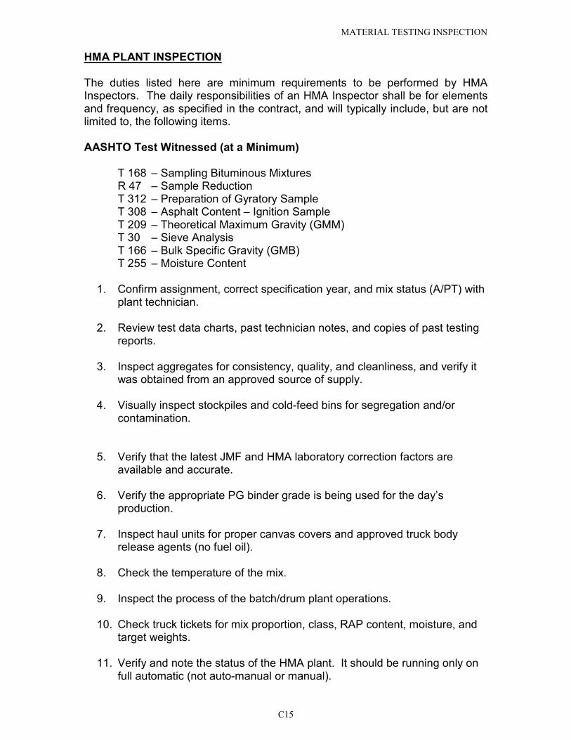
MATERIAL TESTING INSPECTION
C15
HMA PLANT INSPECTION The duties listed here are minimum requirements to be performed by HMA Inspectors. The daily responsibilities of an HMA Inspector shall be for elements and frequency, as specified in the contract, and will typically include, but are not limited to, the following items.
AASHTO Test Witnessed (at a Minimum)
T 168 – Sampling Bituminous Mixtures R 47 – Sample Reduction T 312 – Preparation of Gyratory Sample T 308 – Asphalt Content – Ignition Sample T 209 – Theoretical Maximum Gravity (GMM) T 30 – Sieve Analysis T 166 – Bulk Specific Gravity (GMB) T 255 – Moisture Content
1. Confirm assignment, correct specification year, and mix status (A/PT) with
plant technician.
2. Review test data charts, past technician notes, and copies of past testing reports.
3. Inspect aggregates for consistency, quality, and cleanliness, and verify it was obtained from an approved source of supply.
4. Visually inspect stockpiles and cold-feed bins for segregation and/or contamination.
5. Verify that the latest JMF and HMA laboratory correction factors are available and accurate.
6. Verify the appropriate PG binder grade is being used for the day’s production.
7. Inspect haul units for proper canvas covers and approved truck body release agents (no fuel oil).
8. Check the temperature of the mix.
9. Inspect the process of the batch/drum plant operations.
10. Check truck tickets for mix proportion, class, RAP content, moisture, and target weights.
11. Verify and note the status of the HMA plant. It should be running only on full automatic (not auto-manual or manual).
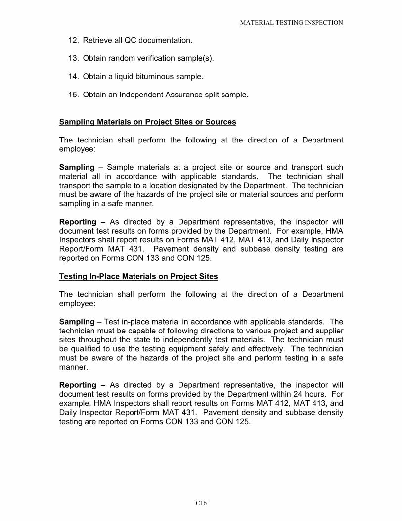
MATERIAL TESTING INSPECTION
C16
12. Retrieve all QC documentation.
13. Obtain random verification sample(s).
14. Obtain a liquid bituminous sample.
15. Obtain an Independent Assurance split sample.
Sampling Materials on Project Sites or Sources The technician shall perform the following at the direction of a Department employee: Sampling – Sample materials at a project site or source and transport such material all in accordance with applicable standards. The technician shall transport the sample to a location designated by the Department. The technician must be aware of the hazards of the project site or material sources and perform sampling in a safe manner. Reporting – As directed by a Department representative, the inspector will document test results on forms provided by the Department. For example, HMA Inspectors shall report results on Forms MAT 412, MAT 413, and Daily Inspector Report/Form MAT 431. Pavement density and subbase density testing are reported on Forms CON 133 and CON 125. Testing In-Place Materials on Project Sites The technician shall perform the following at the direction of a Department employee: Sampling – Test in-place material in accordance with applicable standards. The technician must be capable of following directions to various project and supplier sites throughout the state to independently test materials. The technician must be qualified to use the testing equipment safely and effectively. The technician must be aware of the hazards of the project site and perform testing in a safe manner. Reporting – As directed by a Department representative, the inspector will document test results on forms provided by the Department within 24 hours. For example, HMA Inspectors shall report results on Forms MAT 412, MAT 413, and Daily Inspector Report/Form MAT 431. Pavement density and subbase density testing are reported on Forms CON 133 and CON 125.

MATERIAL TESTING INSPECTION
C17
Testing Material Samples at Department Material Testing Facilities The technician shall perform the following at the direction of a Department employee: Sampling – In accordance with applicable standards, assist or independently test material samples including, but not limited to, concrete cylinders, steel reinforcing bars, chains, fasteners, sand, and Portland cement in a laboratory setting. The technician shall also document the test results, input the test results into the Department’s reporting system, and file the documentation as needed. Assist in the cleaning and maintenance of testing equipment and surrounding areas. Reporting – As directed by a Department representative, the inspector will document test results on forms provided by the Department. Inputting Test Results, Processing Request for Test (MAT-100) Forms, & Filing Documentation The technician shall perform the following at the direction of a Department employee: Request for Test (Form MAT-100) Processing – Through the Department’s computerized construction management system (Site Manager), record test results and status of MAT-100 forms. File hardcopy versions of the MAT-100 forms in the Department’s files.
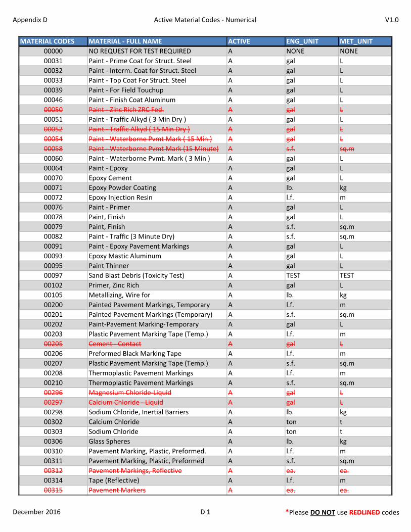
Appendix D Active Material Codes - Numerical V1.0
MATERIAL CODES MATERIAL - FULL NAME ACTIVE ENG_UNIT MET_UNIT
00000 NO REQUEST FOR TEST REQUIRED A NONE NONE
00031 Paint - Prime Coat for Struct. Steel A gal L
00032 Paint - Interm. Coat for Struct. Steel A gal L
00033 Paint - Top Coat For Struct. Steel A gal L
00039 Paint - For Field Touchup A gal L
00046 Paint - Finish Coat Aluminum A gal L
00050 Paint - Zinc Rich ZRC Fed. A gal L
00051 Paint - Traffic Alkyd ( 3 Min Dry ) A gal L
00052 Paint - Traffic Alkyd ( 15 Min Dry ) A gal L
00054 Paint - Waterborne Pvmt Mark ( 15 Min ) A gal L
00058 Paint - Waterborne Pvmt Mark (15 Minute) A s.f. sq.m
00060 Paint - Waterborne Pvmt. Mark ( 3 Min ) A gal L
00064 Paint - Epoxy A gal L
00070 Epoxy Cement A gal L
00071 Epoxy Powder Coating A lb. kg
00072 Epoxy Injection Resin A l.f. m
00076 Paint - Primer A gal L
00078 Paint, Finish A gal L
00079 Paint, Finish A s.f. sq.m
00082 Paint - Traffic (3 Minute Dry) A s.f. sq.m
00091 Paint - Epoxy Pavement Markings A gal L
00093 Epoxy Mastic Aluminum A gal L
00095 Paint Thinner A gal L
00097 Sand Blast Debris (Toxicity Test) A TEST TEST
00102 Primer, Zinc Rich A gal L
00105 Metallizing, Wire for A lb. kg
00200 Painted Pavement Markings, Temporary A l.f. m
00201 Painted Pavement Markings (Temporary) A s.f. sq.m
00202 Paint-Pavement Marking-Temporary A gal L
00203 Plastic Pavement Marking Tape (Temp.) A l.f. m
00205 Cement - Contact A gal L
00206 Preformed Black Marking Tape A l.f. m
00207 Plastic Pavement Marking Tape (Temp.) A s.f. sq.m
00208 Thermoplastic Pavement Markings A l.f. m
00210 Thermoplastic Pavement Markings A s.f. sq.m
00296 Magnesium Chloride-Liquid A gal L
00297 Calcium Chloride - Liquid A gal L
00298 Sodium Chloride, Inertial Barriers A lb. kg
00302 Calcium Chloride A ton t
00303 Sodium Chloride A ton t
00306 Glass Spheres A lb. kg
00310 Pavement Marking, Plastic, Preformed. A l.f. m
00311 Pavement Marking, Plastic, Preformed A s.f. sq.m
00312 Pavement Markings, Reflective A ea. ea.
00314 Tape (Reflective) A l.f. m
00315 Pavement Markers A ea. ea.
December 2016 D 1 *Please DO NOT use REDLINED codes
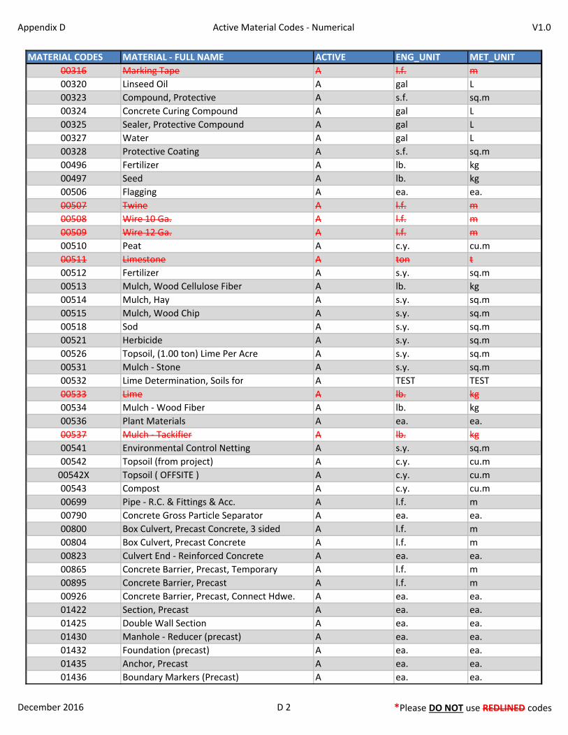
Appendix D Active Material Codes - Numerical V1.0
MATERIAL CODES MATERIAL - FULL NAME ACTIVE ENG_UNIT MET_UNIT
00316 Marking Tape A l.f. m
00320 Linseed Oil A gal L
00323 Compound, Protective A s.f. sq.m
00324 Concrete Curing Compound A gal L
00325 Sealer, Protective Compound A gal L
00327 Water A gal L
00328 Protective Coating A s.f. sq.m
00496 Fertilizer A lb. kg
00497 Seed A lb. kg
00506 Flagging A ea. ea.
00507 Twine A l.f. m
00508 Wire 10 Ga. A l.f. m
00509 Wire 12 Ga. A l.f. m
00510 Peat A c.y. cu.m
00511 Limestone A ton t
00512 Fertilizer A s.y. sq.m
00513 Mulch, Wood Cellulose Fiber A lb. kg
00514 Mulch, Hay A s.y. sq.m
00515 Mulch, Wood Chip A s.y. sq.m
00518 Sod A s.y. sq.m
00521 Herbicide A s.y. sq.m
00526 Topsoil, (1.00 ton) Lime Per Acre A s.y. sq.m
00531 Mulch - Stone A s.y. sq.m
00532 Lime Determination, Soils for A TEST TEST
00533 Lime A lb. kg
00534 Mulch - Wood Fiber A lb. kg
00536 Plant Materials A ea. ea.
00537 Mulch - Tackifier A lb. kg
00541 Environmental Control Netting A s.y. sq.m
00542 Topsoil (from project) A c.y. cu.m
00542X Topsoil ( OFFSITE ) A c.y. cu.m
00543 Compost A c.y. cu.m
00699 Pipe - R.C. & Fittings & Acc. A l.f. m
00790 Concrete Gross Particle Separator A ea. ea.
00800 Box Culvert, Precast Concrete, 3 sided A l.f. m
00804 Box Culvert, Precast Concrete A l.f. m
00823 Culvert End - Reinforced Concrete A ea. ea.
00865 Concrete Barrier, Precast, Temporary A l.f. m
00895 Concrete Barrier, Precast A l.f. m
00926 Concrete Barrier, Precast, Connect Hdwe. A ea. ea.
01422 Section, Precast A ea. ea.
01425 Double Wall Section A ea. ea.
01430 Manhole - Reducer (precast) A ea. ea.
01432 Foundation (precast) A ea. ea.
01435 Anchor, Precast A ea. ea.
01436 Boundary Markers (Precast) A ea. ea.
December 2016 D 2 *Please DO NOT use REDLINED codes
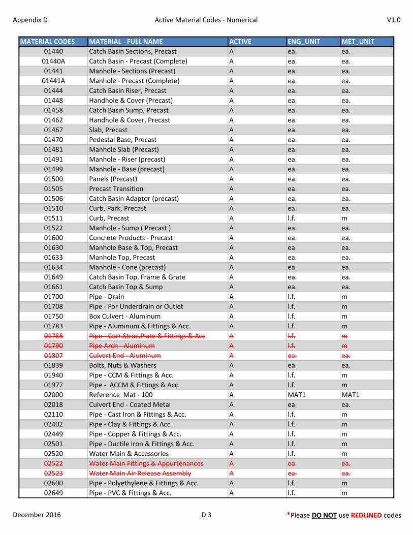
Appendix D Active Material Codes - Numerical V1.0
MATERIAL CODES MATERIAL - FULL NAME ACTIVE ENG_UNIT MET_UNIT
01440 Catch Basin Sections, Precast A ea. ea.
01440A Catch Basin - Precast (Complete) A ea. ea.
01441 Manhole - Sections (Precast) A ea. ea.
01441A Manhole - Precast (Complete) A ea. ea.
01444 Catch Basin Riser, Precast A ea. ea.
01448 Handhole & Cover (Precast) A ea. ea.
01458 Catch Basin Sump, Precast A ea. ea.
01462 Handhole & Cover, Precast A ea. ea.
01467 Slab, Precast A ea. ea.
01470 Pedestal Base, Precast A ea. ea.
01481 Manhole Slab (Precast) A ea. ea.
01491 Manhole - Riser (precast) A ea. ea.
01499 Manhole - Base (precast) A ea. ea.
01500 Panels (Precast) A ea. ea.
01505 Precast Transition A ea. ea.
01506 Catch Basin Adaptor (precast) A ea. ea.
01510 Curb, Park, Precast A ea. ea.
01511 Curb, Precast A l.f. m
01522 Manhole - Sump ( Precast ) A ea. ea.
01600 Concrete Products - Precast A ea. ea.
01630 Manhole Base & Top, Precast A ea. ea.
01633 Manhole Top, Precast A ea. ea.
01634 Manhole - Cone (precast) A ea. ea.
01649 Catch Basin Top, Frame & Grate A ea. ea.
01661 Catch Basin Top & Sump A ea. ea.
01700 Pipe - Drain A l.f. m
01708 Pipe - For Underdrain or Outlet A l.f. m
01750 Box Culvert - Aluminum A l.f. m
01783 Pipe - Aluminum & Fittings & Acc. A l.f. m
01785 Pipe - Corr.Struc.Plate & Fittings & Acc A l.f. m
01790 Pipe Arch - Aluminum A l.f. m
01807 Culvert End - Aluminum A ea. ea.
01839 Bolts, Nuts & Washers A ea. ea.
01940 Pipe - CCM & Fittings & Acc. A l.f. m
01977 Pipe - ACCM & Fittings & Acc. A l.f. m
02000 Reference Mat - 100 A MAT1 MAT1
02018 Culvert End - Coated Metal A ea. ea.
02110 Pipe - Cast Iron & Fittings & Acc. A l.f. m
02402 Pipe - Clay & Fittings & Acc. A l.f. m
02449 Pipe - Copper & Fittings & Acc. A l.f. m
02501 Pipe - Ductile Iron & Fittings & Acc. A l.f. m
02520 Water Main & Accessories A l.f. m
02522 Water Main Fittings & Appurtenances A ea. ea.
02523 Water Main Air Release Assembly A ea. ea.
02600 Pipe - Polyethylene & Fittings & Acc. A l.f. m
02649 Pipe - PVC & Fittings & Acc. A l.f. m
December 2016 D 3 *Please DO NOT use REDLINED codes
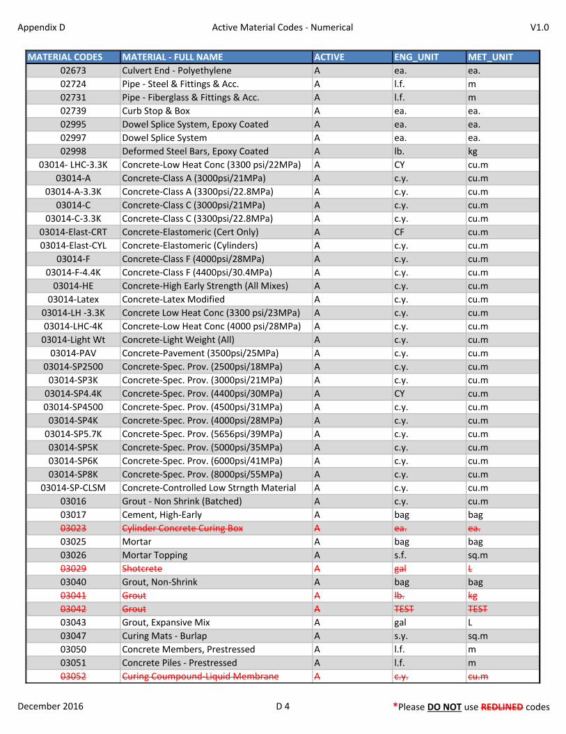
Appendix D Active Material Codes - Numerical V1.0
MATERIAL CODES MATERIAL - FULL NAME ACTIVE ENG_UNIT MET_UNIT
02673 Culvert End - Polyethylene A ea. ea.
02724 Pipe - Steel & Fittings & Acc. A l.f. m
02731 Pipe - Fiberglass & Fittings & Acc. A l.f. m
02739 Curb Stop & Box A ea. ea.
02995 Dowel Splice System, Epoxy Coated A ea. ea.
02997 Dowel Splice System A ea. ea.
02998 Deformed Steel Bars, Epoxy Coated A lb. kg
03014- LHC-3.3K Concrete-Low Heat Conc (3300 psi/22MPa) A CY cu.m
03014-A Concrete-Class A (3000psi/21MPa) A c.y. cu.m
03014-A-3.3K Concrete-Class A (3300psi/22.8MPa) A c.y. cu.m
03014-C Concrete-Class C (3000psi/21MPa) A c.y. cu.m
03014-C-3.3K Concrete-Class C (3300psi/22.8MPa) A c.y. cu.m
03014-Elast-CRT Concrete-Elastomeric (Cert Only) A CF cu.m
03014-Elast-CYL Concrete-Elastomeric (Cylinders) A c.y. cu.m
03014-F Concrete-Class F (4000psi/28MPa) A c.y. cu.m
03014-F-4.4K Concrete-Class F (4400psi/30.4MPa) A c.y. cu.m
03014-HE Concrete-High Early Strength (All Mixes) A c.y. cu.m
03014-Latex Concrete-Latex Modified A c.y. cu.m
03014-LH -3.3K Concrete Low Heat Conc (3300 psi/23MPa) A c.y. cu.m
03014-LHC-4K Concrete-Low Heat Conc (4000 psi/28MPa) A c.y. cu.m
03014-Light Wt Concrete-Light Weight (All) A c.y. cu.m
03014-PAV Concrete-Pavement (3500psi/25MPa) A c.y. cu.m
03014-SP2500 Concrete-Spec. Prov. (2500psi/18MPa) A c.y. cu.m
03014-SP3K Concrete-Spec. Prov. (3000psi/21MPa) A c.y. cu.m
03014-SP4.4K Concrete-Spec. Prov. (4400psi/30MPa) A CY cu.m
03014-SP4500 Concrete-Spec. Prov. (4500psi/31MPa) A c.y. cu.m
03014-SP4K Concrete-Spec. Prov. (4000psi/28MPa) A c.y. cu.m
03014-SP5.7K Concrete-Spec. Prov. (5656psi/39MPa) A c.y. cu.m
03014-SP5K Concrete-Spec. Prov. (5000psi/35MPa) A c.y. cu.m
03014-SP6K Concrete-Spec. Prov. (6000psi/41MPa) A c.y. cu.m
03014-SP8K Concrete-Spec. Prov. (8000psi/55MPa) A c.y. cu.m
03014-SP-CLSM Concrete-Controlled Low Strngth Material A c.y. cu.m
03016 Grout - Non Shrink (Batched) A c.y. cu.m
03017 Cement, High-Early A bag bag
03023 Cylinder Concrete Curing Box A ea. ea.
03025 Mortar A bag bag
03026 Mortar Topping A s.f. sq.m
03029 Shotcrete A gal L
03040 Grout, Non-Shrink A bag bag
03041 Grout A lb. kg
03042 Grout A TEST TEST
03043 Grout, Expansive Mix A gal L
03047 Curing Mats - Burlap A s.y. sq.m
03050 Concrete Members, Prestressed A l.f. m
03051 Concrete Piles - Prestressed A l.f. m
03052 Curing Coumpound-Liquid Membrane A c.y. cu.m
December 2016 D 4 *Please DO NOT use REDLINED codes
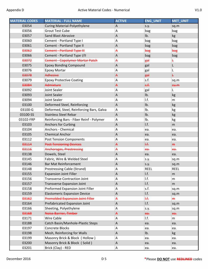
Appendix D Active Material Codes - Numerical V1.0
MATERIAL CODES MATERIAL - FULL NAME ACTIVE ENG_UNIT MET_UNIT
03054 Curing Material-Polyethylene A s.y. sq.m
03056 Grout Test Cube A bag bag
03057 Sand Blast Abrasive A lb. kg
03060 Cement - Portland Type I A bag bag
03061 Cement - Portland Type II A bag bag
03062 Cement - Portland Type III A bag bag
03066 Cement - Portland Type I/II A bag bag
03072 Cement - Copolymer Mortar Patch A gal L
03075 Epoxy Bonding Compound A gal L
03076 Epoxy Mortar A gal L
03078 Adhesive A gal L
03079 Epoxy Protective Coating A s.f. sq.m
03084 Admixture A c.f. cu.m
03092 Joint Sealer A gal L
03093 Joint Sealer A lb. kg
03094 Joint Sealer A l.f. m
03100 Deformed Steel, Reinforcing A lb. kg
03100-G Deformed, Steel, Reinforcing Bars, Galva A lb. kg
03100-SS Stainless Steel Rebar A lb. kg
03102-FRP Reinforcing Bars - Fiber Reinf - Polymer A lb. kg
03103 Anchors for Curbing A l.f. m
03104 Anchors - Chemical A ea. ea.
03105 Chemical Anchor A ea. ea.
03112 Post Tension Components A ea. ea.
03114 Post Tensioning Devices A l.f. m
03116 Anchorages, Prestressing A ea. ea.
03138 Dowels, Steel A ea. ea.
03145 Fabric, Wire & Welded Steel A s.y. sq.m
03146 Bar Mat Reinforcement A s.y. sq.m
03148 Prestressing Cable (Strand) A REEL REEL
03155 Expansion Joint Filler A l.f. m
03156 Transverse Contraction Joint A l.f. m
03157 Transverse Expansion Joint A l.f. m
03158 Preformed Expansion Joint Filler A s.f. sq.m
03159 Elastomeric Expansion Device A l.f. sq.m
03162 Premolded Expansion Joint Filler A l.f. m
03164 Prefabricated Expansion Joint A l.f. sq.m
03166 Sheeting, Polyethylene A s.y. sq.m
03168 Noise Barrier, Timber A ea. ea.
03171 Wire Cable A l.f. m
03188 Catch Basin/Manhole-Plastic Steps A ea. ea.
03197 Concrete Blocks A ea. ea.
03198 Mesh, Reinforcing for Walls A lb. kg
03199 Masonry Brick & Block ( Hollow ) A ea. ea.
03200 Masonry Brick & Block ( Solid ) A ea. ea.
03201 Brick (Clay) - RED A ea. ea.
December 2016 D 5 *Please DO NOT use REDLINED codes
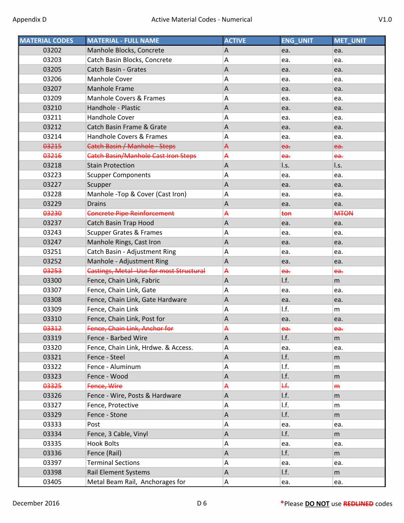
Appendix D Active Material Codes - Numerical V1.0
MATERIAL CODES MATERIAL - FULL NAME ACTIVE ENG_UNIT MET_UNIT
03202 Manhole Blocks, Concrete A ea. ea.
03203 Catch Basin Blocks, Concrete A ea. ea.
03205 Catch Basin - Grates A ea. ea.
03206 Manhole Cover A ea. ea.
03207 Manhole Frame A ea. ea.
03209 Manhole Covers & Frames A ea. ea.
03210 Handhole - Plastic A ea. ea.
03211 Handhole Cover A ea. ea.
03212 Catch Basin Frame & Grate A ea. ea.
03214 Handhole Covers & Frames A ea. ea.
03215 Catch Basin / Manhole - Steps A ea. ea.
03216 Catch Basin/Manhole Cast Iron Steps A ea. ea.
03218 Stain Protection A l.s. l.s.
03223 Scupper Components A ea. ea.
03227 Scupper A ea. ea.
03228 Manhole -Top & Cover (Cast Iron) A ea. ea.
03229 Drains A ea. ea.
03230 Concrete Pipe Reinforcement A ton MTON
03237 Catch Basin Trap Hood A ea. ea.
03243 Scupper Grates & Frames A ea. ea.
03247 Manhole Rings, Cast Iron A ea. ea.
03251 Catch Basin - Adjustment Ring A ea. ea.
03252 Manhole - Adjustment Ring A ea. ea.
03253 Castings, Metal -Use for most Structural A ea. ea.
03300 Fence, Chain Link, Fabric A l.f. m
03307 Fence, Chain Link, Gate A ea. ea.
03308 Fence, Chain Link, Gate Hardware A ea. ea.
03309 Fence, Chain Link A l.f. m
03310 Fence, Chain Link, Post for A ea. ea.
03312 Fence, Chain Link, Anchor for A ea. ea.
03319 Fence - Barbed Wire A l.f. m
03320 Fence, Chain Link, Hrdwe. & Access. A ea. ea.
03321 Fence - Steel A l.f. m
03322 Fence - Aluminum A l.f. m
03323 Fence - Wood A l.f. m
03325 Fence, Wire A l.f. m
03326 Fence - Wire, Posts & Hardware A l.f. m
03327 Fence, Protective A l.f. m
03329 Fence - Stone A l.f. m
03333 Post A ea. ea.
03334 Fence, 3 Cable, Vinyl A l.f. m
03335 Hook Bolts A ea. ea.
03336 Fence (Rail) A l.f. m
03397 Terminal Sections A ea. ea.
03398 Rail Element Systems A l.f. m
03405 Metal Beam Rail, Anchorages for A ea. ea.
December 2016 D 6 *Please DO NOT use REDLINED codes
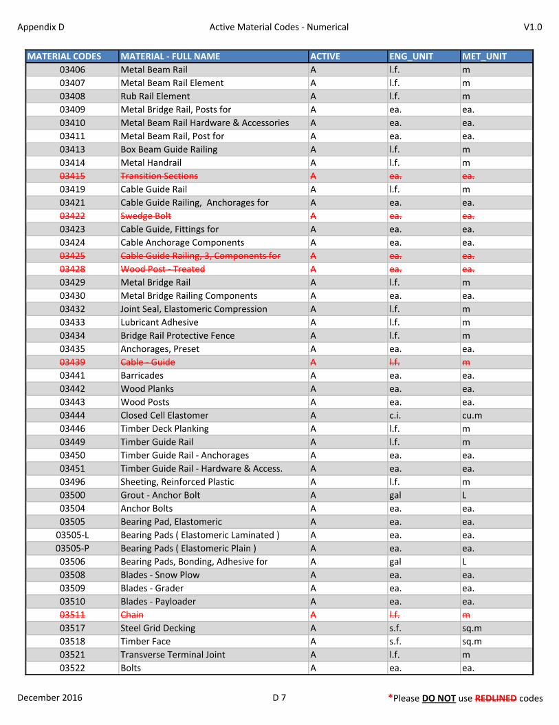
Appendix D Active Material Codes - Numerical V1.0
MATERIAL CODES MATERIAL - FULL NAME ACTIVE ENG_UNIT MET_UNIT
03406 Metal Beam Rail A l.f. m
03407 Metal Beam Rail Element A l.f. m
03408 Rub Rail Element A l.f. m
03409 Metal Bridge Rail, Posts for A ea. ea.
03410 Metal Beam Rail Hardware & Accessories A ea. ea.
03411 Metal Beam Rail, Post for A ea. ea.
03413 Box Beam Guide Railing A l.f. m
03414 Metal Handrail A l.f. m
03415 Transition Sections A ea. ea.
03419 Cable Guide Rail A l.f. m
03421 Cable Guide Railing, Anchorages for A ea. ea.
03422 Swedge Bolt A ea. ea.
03423 Cable Guide, Fittings for A ea. ea.
03424 Cable Anchorage Components A ea. ea.
03425 Cable Guide Railing, 3, Components for A ea. ea.
03428 Wood Post - Treated A ea. ea.
03429 Metal Bridge Rail A l.f. m
03430 Metal Bridge Railing Components A ea. ea.
03432 Joint Seal, Elastomeric Compression A l.f. m
03433 Lubricant Adhesive A l.f. m
03434 Bridge Rail Protective Fence A l.f. m
03435 Anchorages, Preset A ea. ea.
03439 Cable - Guide A l.f. m
03441 Barricades A ea. ea.
03442 Wood Planks A ea. ea.
03443 Wood Posts A ea. ea.
03444 Closed Cell Elastomer A c.i. cu.m
03446 Timber Deck Planking A l.f. m
03449 Timber Guide Rail A l.f. m
03450 Timber Guide Rail - Anchorages A ea. ea.
03451 Timber Guide Rail - Hardware & Access. A ea. ea.
03496 Sheeting, Reinforced Plastic A l.f. m
03500 Grout - Anchor Bolt A gal L
03504 Anchor Bolts A ea. ea.
03505 Bearing Pad, Elastomeric A ea. ea.
03505-L Bearing Pads ( Elastomeric Laminated ) A ea. ea.
03505-P Bearing Pads ( Elastomeric Plain ) A ea. ea.
03506 Bearing Pads, Bonding, Adhesive for A gal L
03508 Blades - Snow Plow A ea. ea.
03509 Blades - Grader A ea. ea.
03510 Blades - Payloader A ea. ea.
03511 Chain A l.f. m
03517 Steel Grid Decking A s.f. sq.m
03518 Timber Face A s.f. sq.m
03521 Transverse Terminal Joint A l.f. m
03522 Bolts A ea. ea.
December 2016 D 7 *Please DO NOT use REDLINED codes
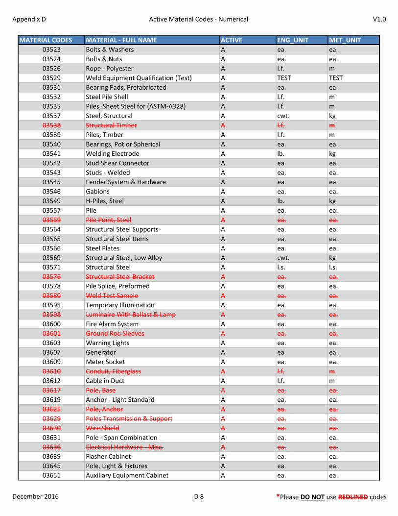
Appendix D Active Material Codes - Numerical V1.0
MATERIAL CODES MATERIAL - FULL NAME ACTIVE ENG_UNIT MET_UNIT
03523 Bolts & Washers A ea. ea.
03524 Bolts & Nuts A ea. ea.
03526 Rope - Polyester A l.f. m
03529 Weld Equipment Qualification (Test) A TEST TEST
03531 Bearing Pads, Prefabricated A ea. ea.
03532 Steel Pile Shell A l.f. m
03535 Piles, Sheet Steel for (ASTM-A328) A l.f. m
03537 Steel, Structural A cwt. kg
03538 Structural Timber A l.f. m
03539 Piles, Timber A l.f. m
03540 Bearings, Pot or Spherical A ea. ea.
03541 Welding Electrode A lb. kg
03542 Stud Shear Connector A ea. ea.
03543 Studs - Welded A ea. ea.
03545 Fender System & Hardware A ea. ea.
03546 Gabions A ea. ea.
03549 H-Piles, Steel A lb. kg
03557 Pile A ea. ea.
03559 Pile Point, Steel A ea. ea.
03564 Structural Steel Supports A ea. ea.
03565 Structural Steel Items A ea. ea.
03566 Steel Plates A ea. ea.
03569 Structural Steel, Low Alloy A cwt. kg
03571 Structural Steel A l.s. l.s.
03576 Structural Steel Bracket A ea. ea.
03578 Pile Splice, Preformed A ea. ea.
03580 Weld Test Sample A ea. ea.
03595 Temporary Illumination A ea. ea.
03598 Luminaire With Ballast & Lamp A ea. ea.
03600 Fire Alarm System A ea. ea.
03601 Ground Rod Sleeves A ea. ea.
03603 Warning Lights A ea. ea.
03607 Generator A ea. ea.
03609 Meter Socket A ea. ea.
03610 Conduit, Fiberglass A l.f. m
03612 Cable in Duct A l.f. m
03617 Pole, Base A ea. ea.
03619 Anchor - Light Standard A ea. ea.
03625 Pole, Anchor A ea. ea.
03629 Poles Transmission & Support A ea. ea.
03630 Wire Shield A ea. ea.
03631 Pole - Span Combination A ea. ea.
03636 Electrical Hardware - Misc. A ea. ea.
03639 Flasher Cabinet A ea. ea.
03645 Pole, Light & Fixtures A ea. ea.
03651 Auxiliary Equipment Cabinet A ea. ea.
December 2016 D 8 *Please DO NOT use REDLINED codes

Appendix D Active Material Codes - Numerical V1.0
MATERIAL CODES MATERIAL - FULL NAME ACTIVE ENG_UNIT MET_UNIT
03688 Light Standard & Bracket A ea. ea.
03690 Anchor, Miscellaneous Hardware for A ea. ea.
03691 Nuts and/or Washers A ea. ea.
03693 Conduit & Fittings (all types) A l.f. m
03696 Cable - Aerial A l.f. m
03697 Bracket - (Illumination) For Wood Pole A ea. ea.
03698 Wood Pole For Illumination A ea. ea.
03704 Light Standard A ea. ea.
03705 Tape A l.f. m
03707 Bolts, High Strength A ea. ea.
03708 Rock Anchor A ea. ea.
03709 Ground Wire A l.f. m
03710 Ground Rod & Clamp A ea. ea.
03711 Ground Rod A ea. ea.
03715 Lamp Ballast, Mercury Vapor A ea. ea.
03723 Rigid Metal Conduit A l.f. m
03724 Junction Box & Cover A ea. ea.
03725 Single Conductor In Conduit A l.f. m
03728 Service Entrance & Cabinet A ea. ea.
03729 Navigation Lights A ea. ea.
03730 Single Conductor A l.f. m
03731 Aviation Lights A ea. ea.
03734 Metal Conduit & Fittings A l.f. m
03735 Signs - Internally Illuminated A ea. ea.
03743 Conduit & Appurtenances A l.f. m
03745 Amplifier A ea. ea.
03748 Signal Accessories A ea. ea.
03753 Bushings A ea. ea.
03754 Clamp A ea. ea.
03756 Straps A ea. ea.
03758 Circuit Breakers A ea. ea.
03760 Flasher E/M A ea. ea.
03762 170 Controller & Cabinet A ea. ea.
03764 Sign (Variable Message) A ea. ea.
03765 Pedestrian Push Button & Sign A ea. ea.
03766 Traffic Signal Equipment A ea. ea.
03774 Service Cabinet & Components A ea. ea.
03775 Service Components A ea. ea.
03777 Service Electrical A ea. ea.
03778 Lighting Fixtures A ea. ea.
03779 Grounding Connectors A ea. ea.
03786 Arrow Signal A ea. ea.
03793 Optical Detector A ea. ea.
03794 Vehicle Emitter A ea. ea.
03795 Phase Selector A ea. ea.
03797 Detectors A ea. ea.
December 2016 D 9 *Please DO NOT use REDLINED codes

Appendix D Active Material Codes - Numerical V1.0
MATERIAL CODES MATERIAL - FULL NAME ACTIVE ENG_UNIT MET_UNIT
03798 Temporary Signalization A ea. ea.
03799 Bracket A ea. ea.
03800 Traffic Signal Foundation A ea. ea.
03801 Pedestals, Aluminum or Steel A ea. ea.
03802 Span Pole - Steel A ea. ea.
03803 Flashing Arrow A ea. ea.
03804 Span Pole - Wood A ea. ea.
03805 Wood Pole Anchor A ea. ea.
03806 Mast Arm Assembly A ea. ea.
03807 Traffic Signal A ea. ea.
03808 Pedestrian Signal A ea. ea.
03809 Pedestrian Push Buttons A ea. ea.
03810 Controller A ea. ea.
03812 Loop Vehicle Detector A ea. ea.
03813 Loop Detector Saw Cut Materials A ea. ea.
03814 Loop Detector, Wire for A l.f. m
03815 Loop Detector, Plastic Compound for A gal L
03817 Vehicle Detector A ea. ea.
03843 Control Cable, Multi Conductor A l.f. m
03844 Control Cable A l.f. m
03848 Span Wire A l.f. m
03849 Conduit, Polyvinyl Chloride A l.f. m
03854 Span Wire Assembly A ea. ea.
03855 Wire, Electrical A l.f. m
03856 Wire And Duct A l.f. m
03858 Duct Bank - PVC A l.f. m
03861 Traffic Control Cabinet A ea. ea.
03862 Pole A ea. ea.
03864 Traffic Signal Lamp A ea. ea.
03865 Vehicle Detector and Amplifier A ea. ea.
03867 Communication Equipment A ea. ea.
03869 Test Equipment A ea. ea.
03874 Cable Clamp A ea. ea.
03875 Cable Closures A ea. ea.
03878 Conduit (Metal) Liquid Tight A l.f. m
03881 Messenger Cable and Hardware A l.f. m
03882 Guy Wire A l.f. m
03883 Guy Wire Shield A ea. ea.
03893 Tubular Sign Support A ea. ea.
03895 Post - Sign A ea. ea.
03898 Support Bracket A ea. ea.
03899 Sign Support (Cantilever) A ea. ea.
03900 Sign Supports, Structural Steel A cwt. kg
03927 Traffic Drum A ea. ea.
03928 Sign Support (Overhead) A ea. ea.
03929 Sign Support, Structure Mounted A ea. ea.
December 2016 D 10 *Please DO NOT use REDLINED codes
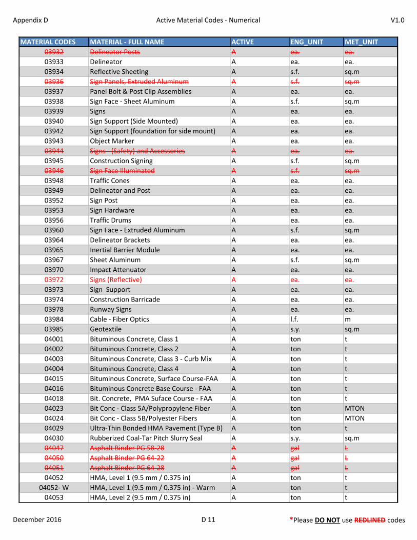
Appendix D Active Material Codes - Numerical V1.0
MATERIAL CODES MATERIAL - FULL NAME ACTIVE ENG_UNIT MET_UNIT
03932 Delineator Posts A ea. ea.
03933 Delineator A ea. ea.
03934 Reflective Sheeting A s.f. sq.m
03936 Sign Panels, Extruded Aluminum A s.f. sq.m
03937 Panel Bolt & Post Clip Assemblies A ea. ea.
03938 Sign Face - Sheet Aluminum A s.f. sq.m
03939 Signs A ea. ea.
03940 Sign Support (Side Mounted) A ea. ea.
03942 Sign Support (foundation for side mount) A ea. ea.
03943 Object Marker A ea. ea.
03944 Signs - (Safety) and Accessories A ea. ea.
03945 Construction Signing A s.f. sq.m
03946 Sign Face Illuminated A s.f. sq.m
03948 Traffic Cones A ea. ea.
03949 Delineator and Post A ea. ea.
03952 Sign Post A ea. ea.
03953 Sign Hardware A ea. ea.
03956 Traffic Drums A ea. ea.
03960 Sign Face - Extruded Aluminum A s.f. sq.m
03964 Delineator Brackets A ea. ea.
03965 Inertial Barrier Module A ea. ea.
03967 Sheet Aluminum A s.f. sq.m
03970 Impact Attenuator A ea. ea.
03972 Signs (Reflective) A ea. ea.
03973 Sign Support A ea. ea.
03974 Construction Barricade A ea. ea.
03978 Runway Signs A ea. ea.
03984 Cable - Fiber Optics A l.f. m
03985 Geotextile A s.y. sq.m
04001 Bituminous Concrete, Class 1 A ton t
04002 Bituminous Concrete, Class 2 A ton t
04003 Bituminous Concrete, Class 3 - Curb Mix A ton t
04004 Bituminous Concrete, Class 4 A ton t
04015 Bituminous Concrete, Surface Course-FAA A ton t
04016 Bituminous Concrete Base Course - FAA A ton t
04018 Bit. Concrete, PMA Suface Course - FAA A ton t
04023 Bit Conc - Class 5A/Polypropylene Fiber A ton MTON
04024 Bit Conc - Class 5B/Polyester Fibers A ton MTON
04029 Ultra-Thin Bonded HMA Pavement (Type B) A ton t
04030 Rubberized Coal-Tar Pitch Slurry Seal A s.y. sq.m
04047 Asphalt Binder PG 58-28 A gal L
04050 Asphalt Binder PG 64-22 A gal L
04051 Asphalt Binder PG 64-28 A gal L
04052 HMA, Level 1 (9.5 mm / 0.375 in) A ton t
04052- W HMA, Level 1 (9.5 mm / 0.375 in) - Warm A ton t
04053 HMA, Level 2 (9.5 mm / 0.375 in) A ton t
December 2016 D 11 *Please DO NOT use REDLINED codes
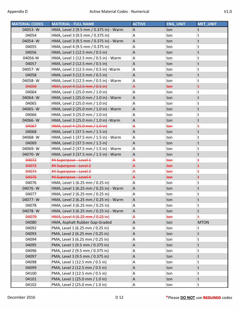
Appendix D Active Material Codes - Numerical V1.0
MATERIAL CODES MATERIAL - FULL NAME ACTIVE ENG_UNIT MET_UNIT
04053- W HMA, Level 2 (9.5 mm / 0.375 in) - Warm A ton t
04054 HMA, Level 3 (9.5 mm / 0.375 in) A ton t
04054- W HMA, Level 3 (9.5 mm / 0.375 in) - Warm A ton t
04055 HMA, Level 4 (9.5 mm / 0.375 in) A ton t
04056 HMA, Level 1 (12.5 mm / 0.5 in) A ton t
04056-W HMA, Level 1 (12.5 mm / 0.5 in) - Warm A ton t
04057 HMA, Level 2 (12.5 mm / 0.5 in) A ton t
04057- W HMA, Level 2 (12.5 mm / 0.5 in) -Warm A ton t
04058 HMA, Level 3 (12.5 mm / 0.5 in) A ton t
04058- W HMA, Level 3 (12.5 mm / 0.5 in) - Warm A ton t
04059 HMA, Level 4 (12.5 mm / 0.5 in) A ton t
04064 HMA, Level 1 (25.0 mm / 1.0 in) A ton t
04064- W HMA, Level 1 (25.0 mm / 1.0 in) - Warm A ton t
04065 HMA, Level 2 (25.0 mm / 1.0 in) A ton t
04065- W HMA, Level 2 (25.0 mm / 1.0 in) - Warm A ton t
04066 HMA, Level 3 (25.0 mm / 1.0 in) A ton t
04066- W HMA, Level 3 (25.0 mm / 1.0 in) -Warm A ton t
04067 HMA, Level 4 (25.0 mm / 1.0 in) A ton t
04068 HMA, Level 1 (37.5 mm / 1.5 in) A ton t
04068- W HMA, Level 1 (37.5 mm / 1.5 in) - Warm A ton t
04069 HMA, Level 2 (37.5 mm / 1.5 in) A ton t
04069- W HMA, Level 2 (37.5 mm / 1.5 in) - Warm A ton t
04070- W HMA, Level 3 (37.5 mm / 1.5 in) - Warm A ton t
04072 #4 Superpave - Level 1 A ton t
04073 #4 Superpave - Level 2 A ton t
04074 #4 Superpave - Level 3 A ton t
04075 #4 Superpave - Level 4 A ton t
04076 HMA, Level 1 (6.25 mm / 0.25 in) A ton t
04076- W HMA, Level 1 (6.25 mm / 0.25 in) - Warm A ton t
04077 HMA, Level 2 (6.25 mm / 0.25 in) A ton t
04077- W HMA, Level 2 (6.25 mm / 0.25 in) - Warm A ton t
04078 HMA, Level 3 (6.25 mm / 0.25 in) A ton t
04078- W HMA, Level 3 (6.25 mm / 0.25 in) - Warm A ton t
04079 HMA, Level 4 (6.25 mm / 0.25 in) A ton t
04080 HMA, Asphalt Rubber Gap-Graded A ton MTON
04092 PMA, Level 1 (6.25 mm / 0.25 in) A ton t
04093 PMA, Level 2 (6.25 mm / 0.25 in) A ton t
04094 PMA, Level 3 (6.25 mm / 0.25 in) A ton t
04095 PMA, Level 1 (9.5 mm / 0.375 in) A ton t
04096 PMA, Level 2 (9.5 mm / 0.375 in) A ton t
04097 PMA, Level 3 (9.5 mm / 0.375 in) A ton t
04098 PMA, Level 1 (12.5 mm / 0.5 in) A ton t
04099 PMA, Level 2 (12.5 mm / 0.5 in) A ton t
04100 PMA, Level 3 (12.5 mm / 0.5 in) A ton t
04101 PMA, Level 1 (25.0 mm / 1.0 in) A ton t
04102 PMA, Level 2 (25.0 mm / 1.0 in) A ton t
December 2016 D 12 *Please DO NOT use REDLINED codes
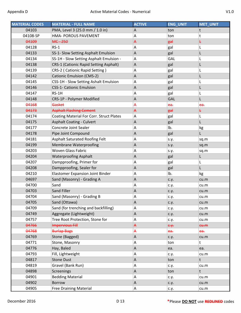
Appendix D Active Material Codes - Numerical V1.0
MATERIAL CODES MATERIAL - FULL NAME ACTIVE ENG_UNIT MET_UNIT
04103 PMA, Level 3 (25.0 mm / 1.0 in) A ton t
04108-SP HMA- POROUS PAVEMENT A ton t
04109 MC - 250 A gal L
04128 RS-1 A gal L
04133 SS-1- Slow Setting Asphalt Emulsion A gal L
04134 SS-1H - Slow Setting Asphalt Emulsion - A GAL L
04138 CRS-1 (Cationic Rapid Setting Asphalt) A gal L
04139 CRS-2 ( Cationic Rapid Setting ) A gal L
04142 Cationic Emulsion (CMS-2) A gal L
04145 CSS-1H - Slow Setting Ashalt Emulsion A gal L
04146 CSS-1- Cationic Emulsion A gal L
04147 RS-1H A gal L
04148 CRS-1P - Polymer Modified A GAL L
04168 Gasket A ea. ea.
04173 Asphalt Flashing Cement A gal L
04174 Coating Material For Corr. Struct Plates A gal L
04175 Asphalt Coating - Culvert A gal L
04177 Concrete Joint Sealer A lb. kg
04178 Pipe Joint Compound A gal L
04181 Asphalt Saturated Roofing Felt A s.y. sq.m
04199 Membrane Waterproofing A s.y. sq.m
04203 Woven Glass Fabric A s.y. sq.m
04204 Waterproofing Asphalt A gal L
04207 Dampproofing, Primer for A gal L
04208 Dampproofing, Sealer for A gal L
04210 Elastomer Expansion Joint Binder A lb. kg
04697 Sand (Masonry) - Grading A A c.y. cu.m
04700 Sand A c.y. cu.m
04703 Sand Filler A c.y. cu.m
04704 Sand (Masonry) - Grading B A c.y. cu.m
04705 Sand (Ottawa) A c.y. cu.m
04709 Sand (for trenching and backfilling) A c.y. cu.m
04749 Aggregate (Lightweight) A c.y. cu.m
04757 Tree Root Protection, Stone for A c.y. cu.m
04766 Impervious Fill A c.y. cu.m
04768 Burlap Bags A ea. ea.
04769 Stone (Bagged) A c.y. cu.m
04771 Stone, Masonry A ton t
04776 Hay, Baled A ea. ea.
04793 Fill, Lightweight A c.y. cu.m
04817 Stone Dust A ton t
04819 Gravel (Bank Run) A c.y. cu.m
04898 Screenings A ton t
04901 Bedding Material A c.y. cu.m
04902 Borrow A c.y. cu.m
04905 Free Draining Material A c.y. cu.m
December 2016 D 13 *Please DO NOT use REDLINED codes

Appendix D Active Material Codes - Numerical V1.0
MATERIAL CODES MATERIAL - FULL NAME ACTIVE ENG_UNIT MET_UNIT
04909 Curbing, Granite Stone A l.f. m
04910 Curbing, Granite Slope A l.f. m
04913 Stone for Slope Paving A s.y. sq.m
04914 Sand - Graded A c.y. cu.m
04959 Railroad Ballast Mat A s.f. sq.m
04984 Granite Pavers A ea. ea.
06505 Roofing Felt A s.y. sq.m
06540 Door Frame A ea. ea.
06541 Door A ea. ea.
06552 Lime - Hydrated A bag bag
06558 Insulation A s.f. sq.m
06563 Coal Tar Epoxy for Piling A l.f. m
06566 Lawn Drain A ea. ea.
06567 Asphalt Shingles A s.f. sq.m
06569 Exhaust Fans A ea. ea.
06571 Caulk & Sealant A gal L
06574 Electrical Panel A ea. ea.
06600 Timber For Piles A l.f. m
06604 Cable Connections A l.f. m
06605 Post, Galvanized Steel A ea. ea.
06613 Flashing A l.f. m
06622 Anchor Studs A ea. ea.
06623 Netting A s.f. sq.m
06624 Sealant A l.f. m
06645 Wood Roof Shakes A s.f. sq.m
06647 Picnic Table A ea. ea.
06651 Wire Rope (1/2"/13mm) A l.f. m
06659 Expansion Joint Sealer A l.f. m
06660 Expansion Joint Sealer A s.f. sq.m
06667 Fiberglass Hopper A ea. ea.
06704 Signs Supports (Breakaway) A ea. ea.
06710 Cleanouts A ea. ea.
06713 Drywell - Precast ( Complete ) A ea. ea.
06724 Duct Components A ea. ea.
06725 Cabinet A ea. ea.
06727 Lamp A ea. ea.
06728 Time Clock A ea. ea.
06747 Wood Sign Posts A ea. ea.
06768 Weather Information System A ea. ea.
06779 Ground Bushings W/Lugs A ea. ea.
06780 Locknuts, Steel A ea. ea.
06781 Lighting Switches A ea. ea.
06784 Electrical Tape A ea. ea.
06795 Gate, Slide A ea. ea.
06801 Hangers A ea. ea.
06802 Geogrids A s.y. sq.m
December 2016 D 14 *Please DO NOT use REDLINED codes

Appendix D Active Material Codes - Numerical V1.0
MATERIAL CODES MATERIAL - FULL NAME ACTIVE ENG_UNIT MET_UNIT
06836 Lumber (Southern Yellow Pine) A l.f. m
06841 Elastomeric Joint Sealer A s.f. sq.m
06843 Timber (Treated) A l.f. m
06851 Arch Units - Precast A l.f. m
06854 House Service Connection A l.f. m
06855 Tie Rod A l.f. m
06865 Lubricant A TUBE TUBE
06868 Gate Valve A ea. ea.
06879 Waterstop A l.f. m
06885 Pumping Station & Misc. Materials A ea. ea.
06903 Connectors A ea. ea.
06907 Stainless Steel Strapping A l.f. m
06908 Box Railing (Post) A ea. ea.
06909 Box Railing (Hardware) A ea. ea.
06920 Drain, Flexible Down A l.f. m
06921 Railroad Track & Accessories A l.f. m
06923 Stay In Place Forms A l.f. m
06954 Railroad Crossing - Rubber A ea. ea.
06956 Electrical Equipment A ea. ea.
06960 Signs A s.f. sq.m
06963 Plywood A s.f. sq.m
06990 Galvanizing (Test) A TEST TEST
06994 Cabinet Flasher A ea. ea.
06996 Wire, No. 10 A l.f. m
07000 Washers A ea. ea.
07008 U-Bolt A ea. ea.
07013 Butterfly Valve A ea. ea.
07055 Foam, Polyethylene A l.f. m
07061 Call Box A ea. ea.
07067 Expansion Joint System A l.f. m
07078 Steel Casing A l.f. m
07085 Prefab Building A ea. ea.
07087 Anchor - Guy A ea. ea.
07125 Tapping Sleeve & Valve A ea. ea.
07132 Elastomer A c.i. cu.m
07133 Studs A ea. ea.
07140 Lumber A ea. ea.
07143 Pipe Insulation A l.f. m
07145 Catenary (Temp.) Hold Down Support A ea. ea.
07148 Threaded Reinforcement Bar A l.f. m
07152 Pump A ea. ea.
07156 Valves A ea. ea.
07164 Floodlights A ea. ea.
07172 Water Main Support A ea. ea.
07182 Drainage Composites - Prefabricated A s.y. sq.m
07199 Traffic Guides A ea. ea.
December 2016 D 15 *Please DO NOT use REDLINED codes
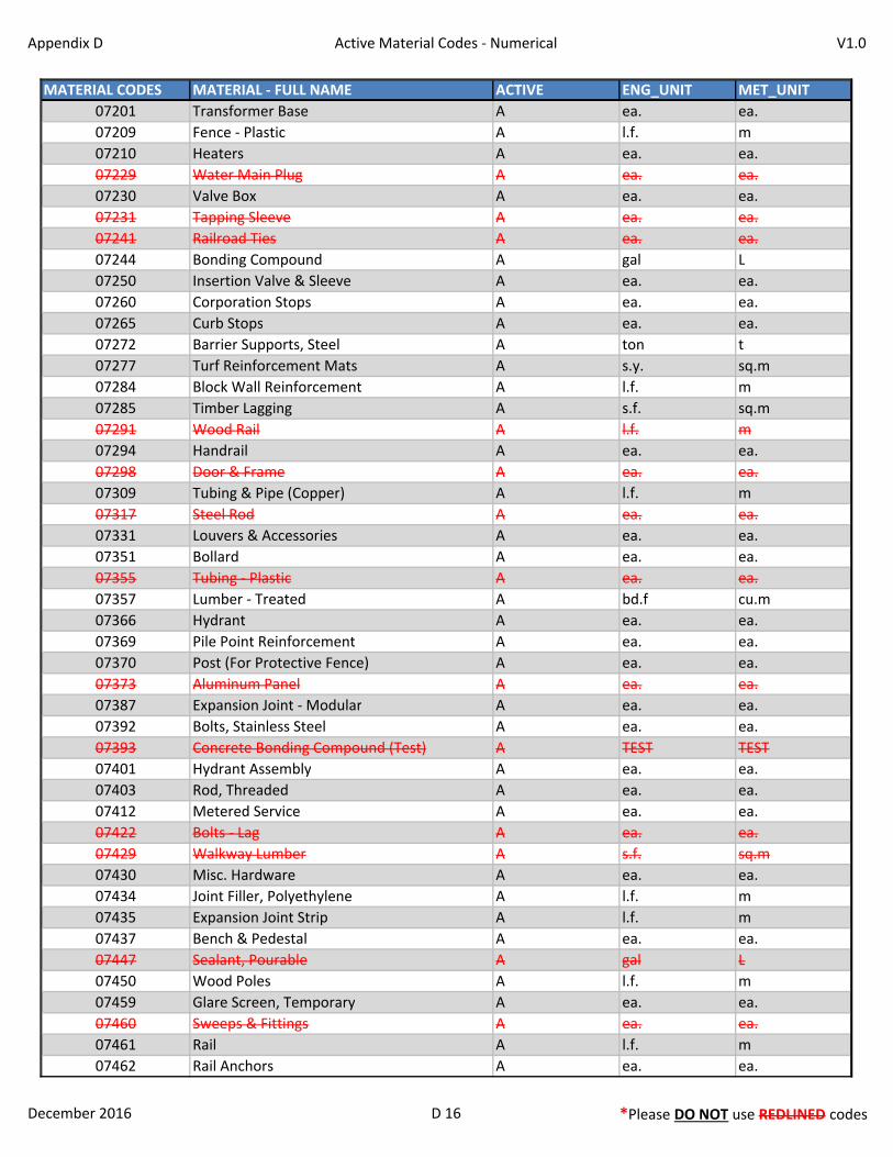
Appendix D Active Material Codes - Numerical V1.0
MATERIAL CODES MATERIAL - FULL NAME ACTIVE ENG_UNIT MET_UNIT
07201 Transformer Base A ea. ea.
07209 Fence - Plastic A l.f. m
07210 Heaters A ea. ea.
07229 Water Main Plug A ea. ea.
07230 Valve Box A ea. ea.
07231 Tapping Sleeve A ea. ea.
07241 Railroad Ties A ea. ea.
07244 Bonding Compound A gal L
07250 Insertion Valve & Sleeve A ea. ea.
07260 Corporation Stops A ea. ea.
07265 Curb Stops A ea. ea.
07272 Barrier Supports, Steel A ton t
07277 Turf Reinforcement Mats A s.y. sq.m
07284 Block Wall Reinforcement A l.f. m
07285 Timber Lagging A s.f. sq.m
07291 Wood Rail A l.f. m
07294 Handrail A ea. ea.
07298 Door & Frame A ea. ea.
07309 Tubing & Pipe (Copper) A l.f. m
07317 Steel Rod A ea. ea.
07331 Louvers & Accessories A ea. ea.
07351 Bollard A ea. ea.
07355 Tubing - Plastic A ea. ea.
07357 Lumber - Treated A bd.f cu.m
07366 Hydrant A ea. ea.
07369 Pile Point Reinforcement A ea. ea.
07370 Post (For Protective Fence) A ea. ea.
07373 Aluminum Panel A ea. ea.
07387 Expansion Joint - Modular A ea. ea.
07392 Bolts, Stainless Steel A ea. ea.
07393 Concrete Bonding Compound (Test) A TEST TEST
07401 Hydrant Assembly A ea. ea.
07403 Rod, Threaded A ea. ea.
07412 Metered Service A ea. ea.
07422 Bolts - Lag A ea. ea.
07429 Walkway Lumber A s.f. sq.m
07430 Misc. Hardware A ea. ea.
07434 Joint Filler, Polyethylene A l.f. m
07435 Expansion Joint Strip A l.f. m
07437 Bench & Pedestal A ea. ea.
07447 Sealant, Pourable A gal L
07450 Wood Poles A l.f. m
07459 Glare Screen, Temporary A ea. ea.
07460 Sweeps & Fittings A ea. ea.
07461 Rail A l.f. m
07462 Rail Anchors A ea. ea.
December 2016 D 16 *Please DO NOT use REDLINED codes
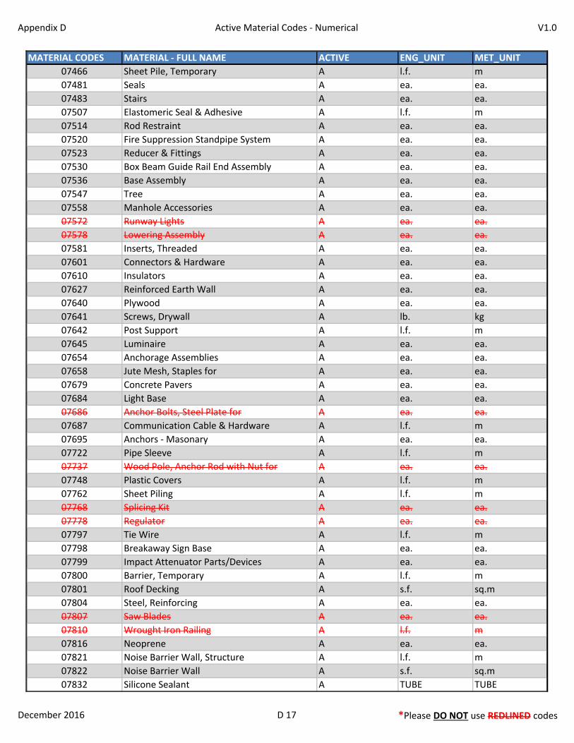
Appendix D Active Material Codes - Numerical V1.0
MATERIAL CODES MATERIAL - FULL NAME ACTIVE ENG_UNIT MET_UNIT
07466 Sheet Pile, Temporary A l.f. m
07481 Seals A ea. ea.
07483 Stairs A ea. ea.
07507 Elastomeric Seal & Adhesive A l.f. m
07514 Rod Restraint A ea. ea.
07520 Fire Suppression Standpipe System A ea. ea.
07523 Reducer & Fittings A ea. ea.
07530 Box Beam Guide Rail End Assembly A ea. ea.
07536 Base Assembly A ea. ea.
07547 Tree A ea. ea.
07558 Manhole Accessories A ea. ea.
07572 Runway Lights A ea. ea.
07578 Lowering Assembly A ea. ea.
07581 Inserts, Threaded A ea. ea.
07601 Connectors & Hardware A ea. ea.
07610 Insulators A ea. ea.
07627 Reinforced Earth Wall A ea. ea.
07640 Plywood A ea. ea.
07641 Screws, Drywall A lb. kg
07642 Post Support A l.f. m
07645 Luminaire A ea. ea.
07654 Anchorage Assemblies A ea. ea.
07658 Jute Mesh, Staples for A ea. ea.
07679 Concrete Pavers A ea. ea.
07684 Light Base A ea. ea.
07686 Anchor Bolts, Steel Plate for A ea. ea.
07687 Communication Cable & Hardware A l.f. m
07695 Anchors - Masonary A ea. ea.
07722 Pipe Sleeve A l.f. m
07737 Wood Pole, Anchor Rod with Nut for A ea. ea.
07748 Plastic Covers A l.f. m
07762 Sheet Piling A l.f. m
07768 Splicing Kit A ea. ea.
07778 Regulator A ea. ea.
07797 Tie Wire A l.f. m
07798 Breakaway Sign Base A ea. ea.
07799 Impact Attenuator Parts/Devices A ea. ea.
07800 Barrier, Temporary A l.f. m
07801 Roof Decking A s.f. sq.m
07804 Steel, Reinforcing A ea. ea.
07807 Saw Blades A ea. ea.
07810 Wrought Iron Railing A l.f. m
07816 Neoprene A ea. ea.
07821 Noise Barrier Wall, Structure A l.f. m
07822 Noise Barrier Wall A s.f. sq.m
07832 Silicone Sealant A TUBE TUBE
December 2016 D 17 *Please DO NOT use REDLINED codes

Appendix D Active Material Codes - Numerical V1.0
MATERIAL CODES MATERIAL - FULL NAME ACTIVE ENG_UNIT MET_UNIT
07850 Catchment, Fiberglass A ea. ea.
07855 Nut, Anchor A ea. ea.
07856 Anchor Plate A ea. ea.
07858 Mesh, Galvanized A s.f. sq.m
07880 Stairway Hardware A ea. ea.
07887 Nails A lb. kg
07935 Cathodic Protection System A ea. ea.
07936 Glare Screen A l.f. m
07946 Joint Filler, Polyethylene Foam A l.f. m
07967 Steel Band A l.f. m
07974 Barricades, Hardware for A ea. ea.
07982 Steel Plate, Galvanized A ea. ea.
07983 Anchor (Barrier) A ea. ea.
07984 Apron Tiedown A ea. ea.
07986 Anchors - Steel For Sign A ton t
07991 Molded Pad A ea. ea.
07995 Steel Grating A s.f. sq.m
07998 Steel Shell A ton t
07999 Wire Mesh A s.f. sq.m
08003 Washer, Stainless Steel A ea. ea.
08004 Pin A ea. ea.
08009 Wire - Loop Vehicle Detector A l.f. m
08010 Expansion Joint - Asphaltic Plug A l.f. m
08010 - SP Exp. Jt.- Asphaltic Plug - SPECIAL PROV. A c.f. cu.m
08018 Stainless Steel Anchor Studs & Nuts A ea. ea.
08022 Bolt (High Strength), Nut & Washer A ea. ea.
08031 To Be Determined A NONE NONE
08032 Sand (Washed) A c.y. cu.m
08033 Sand (Natural) A c.y. cu.m
08034 Stone (Broken/Crushed) A c.y. cu.m
08035 Gravel (Crushed) A c.y. cu.m
08036 Reclaimed Misc. Aggregate ( ON-SITE ) A c.y. cu.m
08036X Reclaimed Misc. Aggregate ( OFFSITE ) A c.y. cu.m
08037 Reclaimed Waste A c.y. cu.m
08037X Reclaimed Waste ( OFFSITE ) A c.y. cu.m
08038 Subgrade A s.y. sq.m
08039 Embankment Material A c.y. cu.m
08042 Pull Box - Precast Concrete A ea. ea.
08043 Traffic Control Equipment A ea. ea.
08044 Retaining Wall - Precast Concrete A ea. ea.
08045 Pipe - Liner A l.f. m
08046 Camera Video Detection System A ea. ea.
08047 Camera Cable A l.f. m
08050 Monument A ea. ea.
08051 Lawn Sprinkler System A ea. ea.
08052 Helix Pier A ea. ea.
December 2016 D 18 *Please DO NOT use REDLINED codes

Appendix D Active Material Codes - Numerical V1.0
MATERIAL CODES MATERIAL - FULL NAME ACTIVE ENG_UNIT MET_UNIT
08053 Wood Log A ea. ea.
08054 Wetland Soil A c.y. cu.m
08055 Low Density Cellular Concrete Fill A c.y. cu.m
08056 Oil Absorbent Boom A l.f. m
08058 Containment Boom A l.f. m
08059 Turbidity Control Curtains A l.f. m
08060 Detectable Warning Strip - (ADA) A s.f. sq.m
08062 Bridge Plate A ea. ea.
08063 Video Equipment A ea. ea.
08064 Warning Paver A ea. ea.
08065 Counterweight Blocks A ea. ea.
08066 Vehicle Arresting System A ea. ea.
08067 SILTSACK A ea. ea.
December 2016 D 19 *Please DO NOT use REDLINED codes
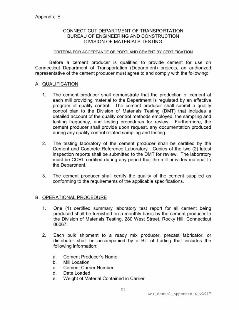
Appendix E
E1 DMT_Manual_Appendix E_v2017
CONNECTICUT DEPARTMENT OF TRANSPORTATION BUREAU OF ENGINEERING AND CONSTRUCTION
DIVISION OF MATERIALS TESTING
CRITERIA FOR ACCEPTANCE OF PORTLAND CEMENT BY CERTIFICATION
Before a cement producer is qualified to provide cement for use on Connecticut Department of Transportation (Department) projects, an authorized representative of the cement producer must agree to and comply with the following: A. QUALIFICATION
1. The cement producer shall demonstrate that the production of cement at each mill providing material to the Department is regulated by an effective program of quality control. The cement producer shall submit a quality control plan to the Division of Materials Testing (DMT) that includes a detailed account of the quality control methods employed, the sampling and testing frequency, and testing procedures for review. Furthermore, the cement producer shall provide upon request, any documentation produced during any quality control related sampling and testing.
2. The testing laboratory of the cement producer shall be certified by the
Cement and Concrete Reference Laboratory. Copies of the two (2) latest inspection reports shall be submitted to the DMT for review. The laboratory must be CCRL certified during any period that the mill provides material to the Department.
3. The cement producer shall certify the quality of the cement supplied as
conforming to the requirements of the applicable specifications. B. OPERATIONAL PROCEDURE
1. One (1) certified summary laboratory test report for all cement being produced shall be furnished on a monthly basis by the cement producer to the Division of Materials Testing, 280 West Street, Rocky Hill, Connecticut 06067.
2. Each bulk shipment to a ready mix producer, precast fabricator, or
distributor shall be accompanied by a Bill of Lading that includes the following information:
a. Cement Producer’s Name b. Mill Location c. Cement Carrier Number d. Date Loaded e. Weight of Material Contained in Carrier

Appendix E
E2 DMT_Manual_Appendix E_v2017
f. Silo, Bin or Lot Number of Cement, Terminals g. Consignee h. Destination i. Cement Type
Original BOL’s must be provided to the purchaser for retention and review by the Department.
3. Random samples of the cement supplied may be selected and tested by
the Department. Results of tests on these samples may be compared with the certified test values provided by the cement producer.
4. Results from bulk cement testing may also apply to bagged material from the same source.
Failure of the cement producer to comply with the requirements of the operational procedure may be considered grounds for suspending the qualification of the cement producer to provide cement on the basis of certification.
The procedure outlined above is intended to establish general guidelines for the acceptance of cement on the basis of producer qualification. However, the ConnDOT reserves the right to modify the above requirements if the best interest of the Department is served.
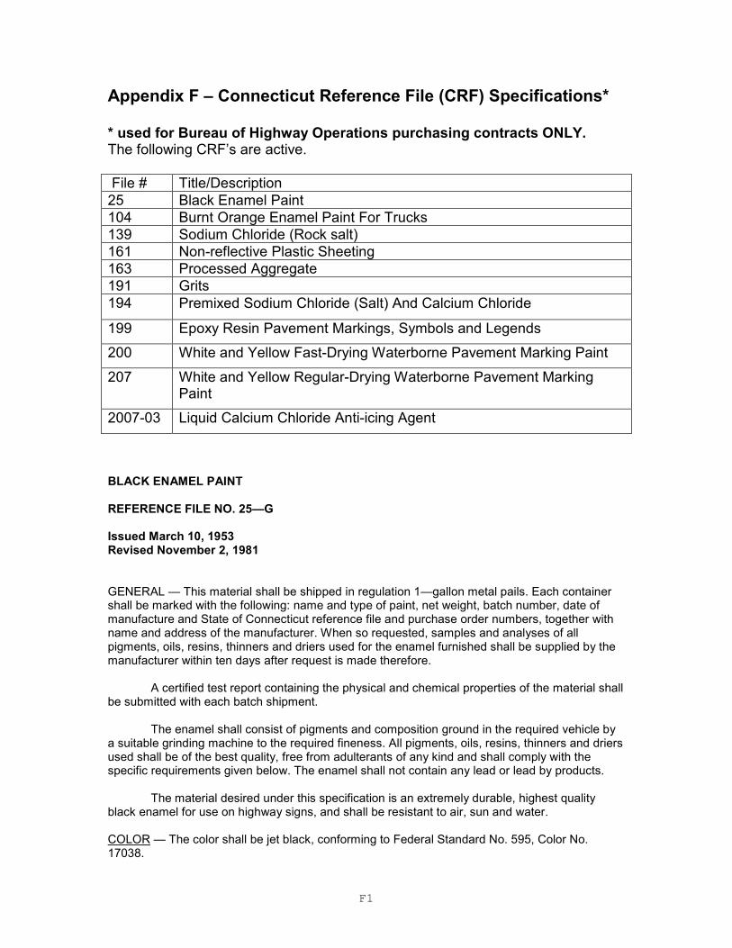
F1
Appendix F – Connecticut Reference File (CRF) Specifications* * used for Bureau of Highway Operations purchasing contracts ONLY. The following CRF’s are active.
File # Title/Description
25 Black Enamel Paint
104 Burnt Orange Enamel Paint For Trucks
139 Sodium Chloride (Rock salt)
161 Non-reflective Plastic Sheeting
163 Processed Aggregate
191 Grits
194 Premixed Sodium Chloride (Salt) And Calcium Chloride
199 Epoxy Resin Pavement Markings, Symbols and Legends
200 White and Yellow Fast-Drying Waterborne Pavement Marking Paint
207 White and Yellow Regular-Drying Waterborne Pavement Marking Paint
2007-03 Liquid Calcium Chloride Anti-icing Agent
BLACK ENAMEL PAINT REFERENCE FILE NO. 25—G Issued March 10, 1953 Revised November 2, 1981 GENERAL — This material shall be shipped in regulation 1—gallon metal pails. Each container shall be marked with the following: name and type of paint, net weight, batch number, date of manufacture and State of Connecticut reference file and purchase order numbers, together with name and address of the manufacturer. When so requested, samples and analyses of all pigments, oils, resins, thinners and driers used for the enamel furnished shall be supplied by the manufacturer within ten days after request is made therefore.
A certified test report containing the physical and chemical properties of the material shall be submitted with each batch shipment.
The enamel shall consist of pigments and composition ground in the required vehicle by a suitable grinding machine to the required fineness. All pigments, oils, resins, thinners and driers used shall be of the best quality, free from adulterants of any kind and shall comply with the specific requirements given below. The enamel shall not contain any lead or lead by products.
The material desired under this specification is an extremely durable, highest quality
black enamel for use on highway signs, and shall be resistant to air, sun and water.
COLOR — The color shall be jet black, conforming to Federal Standard No. 595, Color No. 17038.
F2
ENAMEL COMPOSITION
MIN. MAX.
Carbon Black, % 3 4
Total solids, % by weight 42 -
Coarse particles retained on #325 screen based on paint, % - 0.5 Weight per gallon, lb. 7.5 --
Viscosity, Krebs units at 77˚F. 67 77
Fitneness of grind (North Standard) 7 --
PIGMENT COMPOSITION — The pigment shall be carbon black only. VEHICLE - The vehicle shall consist of a phthalic alkyd resin conforming to the requirements of Federal Specification TT—R-266, Type 3, of latest issue, with the following exceptions: Viscosity - Z maximum; Compatibility — delete raw linseed oil and mineral spirits dilution tests. The necessary quantities of suitable aliphatic, aromatic or terpene thinners and driers shall be added to yield a product conforming to all the requirements of this specification. SPECULAR GLOSS - The enamel shall be flowed on a tin panel and allowed to dry for 24 hours before measuring. The specular gloss at 60º angle of incident, ASTM designation D523 of latest issue, shall be not less than 85. SETTING AND DRYING TIME — This enamel shall air dry dust free within 2 hours, dry hard within 8 hours and reach full hardness within 48 hours. DRY OPACITY — This enamel shall have a contrast ratio of at least 0.99 when spread at the rate of 630 sq. ft. per gallon (0.0025—inch wet film thickness). WATER RESISTANCE — A film of enamel 0.002 inch thick shall be allowed to air dry for 96 hours, and then immersed in distilled water for 16 hours. It shall show no blistering or wrinkling immediately upon removal and no more than slight dulling or whitening after 2 hours recovery. After 24 hours, the gloss of the immersed portion shall be at least 90 percent of a comparison panel, which was not immersed. FLEXIBILITY - A film of enamel 0.002 inch thick shall be allowed to dry for 18 hours, then baked for 72 hours at 105± 2°C, allowed to cool for 1/2 hour at 25°c (77°F), then bent over an 1/8—inch mandrel. There shall be no visible cracks when examined in a strong light at a 7—diameter magnification. SKINNING — The enamel shall not skin within 48 hours in a three—quarter filled, closed container. Small amounts of anti—skinning agents, wetting agents, suspension agents and anti—drier agents may be added at the discretion of the manufacturer. WORKING PROPERTIES — The enamel shall be well ground and shall show no more settling or caking than may be easily redispursed with a paddle to a homogeneous state. It shall be of good brushing consistency and shall dry to a smooth, glossy, uniform film, free from running, sagging or streaking.
F3
BURNT ORANGE ENAMEL PAINT FOR TRUCKS (LEAD FREE) REFERENCE FILE NO. 104-P Issued May 17, 1945 Revised January 25, 1999
INTENDED USE – This specification covers a lead-free high-grade, synthetic-type high gloss enamel intended for use on trucks and other metallic motorized mechanical equipment. It is highly weather-resistant and is characterized by excellent color and gloss-retention, good drying, flexibility and freedom from aftertack. This enamel may be applied by brush or spray. It fails by mild chalking rather than by checking or cracking. The application of wax at periodic intervals will retard chalking and improve the appearance of the finish. GENERAL – This material shall consist of pigments of the required fineness and composition, ground in the specified vehicle by a suitable grinding machine to the required fineness. All pigments, oils, resins, thinners and driers shall comply with the requirements below. This enamel shall be shipped in regulation one-or five-gallon metal pails, as specified by the Purchasing Department. Each container shall be marked with the following: name and type of paint, net weight, batch number, date of manufacture and State of Connecticut Reference File and Purchase Order Numbers, together with the name and address of the manufacturer. When so requested, samples and, analyses of all pigments, oils, resins, thinners, and driers used shall be supplied by the manufacture within ten (10) days after request is made. COLOR – Standard color chips may be viewed at the Connecticut Department of Transportation, Research and Materials Testing Laboratory, 280 West Street, Rocky Hill, Connecticut 06067. The color shall essentially match that of color Omaha Orange, DuPont #082. VEHICLE - The vehicle for this air-drying enamel shall consist of a phthalic alkyd resin. Necessary quantities of suitable aliphatic, aromatic or tarpene thinners and driers, or mixture thereof, shall be added to yield a product conforming to all the requirements of this specification. Small amounts of antiskinning agents, wetting agents, suspension agents and antidrier absorption agents may be added at the discretion of the manufacturer.
QUANTITITIVE REQUIREMENTS Min. Max. Pigment, % by weight 16 Vehicle, % by weight -- 84 Volatile matter in vehicle, % by weight -- 55 Coarse particles and skins retained on #325 sieve, % by weight of pigment -- 0.5 Viscosity, Krebs units at 77˚F. 75 85 Specular gloss (without correction for diffuse reflectance) 85 Fineness of grind (North Standard) 6 Dry opacity (540 sq. ft. per gallon) 0.52 Weight per gallon, lbs. 8.0 Drying time: Dust-free setting time, hours -- 1 Dry hard, hours -- 8 Full hardness, hours -- 48 BRUSHING PROPERTIES – As received, this enamel shall be ready-mixed for use. It shall be of good brushing consistency in the packaged condition. When tested as described below, laps
F4
shall be picked up without pulling under the brush; and the enamel shall dry to a smooth, glossy, uniform film, free from running, sagging or streaking. Brush the evenly mixed enamel on a thoroughly cleaned, rust-free, smooth, cold-rolled steel or aluminum panel (2 ft. square) with a 2-1/2 inch paint brush, applying the enamel uniformly at an approximately spreading rate of 500 square feet per gallon. Place the panel in a nearly vertical position, allow to air dry for 24 hours and examine for defects described above. DRYING TIME – A wet film, 0.0015-inch thick, shall set to a dust-free condition within one hour, dry hard and tack-free within 8-hours and reach full hardness within 48 hours. FILM FOR FLEXIBILITY, WATER-RESISTANCE AND GASOLINE-RESISTANCE – Tin panels, measuring 4 by 6 inches and weighing 19 to 25 grams per square centimeter, will be used for this test. They will be thoroughly cleaned with a suitable solvent and lightly buffed with steel wool immediately before using. Apply the film with a 0.002-inch (approximately 0.004-inch gap clearance). Bird Film Applicator or any other doctor blade which produces a film of the same thickness as that produced by the Bird blade. FLEXIBILLITY – Films prepared as above shall be allowed to air dry in a horizontal position for 18 hours, then baked for 168 hours at 105 + 2˚C (221 + 4˚F). After baking, condition the panel for one-half hour at 23 + 1˚C (73.4 + 2˚F) and relative humidity 50% - 4%. Bend over a 1/8 inch mandrel. Examine the coating for cracks over the area of the bend in a strong light at a 7-diameter magnification. The film of the enamel shall show no cracking. APPEARANCE OF FILM AFTER BAKING – After drying and baking the panel for flexibility, the enamel film shall retain at least 75 percent of the original secular gloss value. ADHESION – In testing for adhesion, use the flat portion of the panel from the flexibility test. Cut a narrow ribbon of the film from the panel by use of the sharp knife blade held at about 30 degrees from the panel. The film should cut loose in the form of a ribbon without flaking or cracking. COLOR WATER RESISTANCE – After drying for 96 hours, place one of the test panels in a beaker containing approximately 2-1/2 inches of distilled water at room temperature (21 to 32˚C), and allow to remain for 16 hours. Remove and allow to dry. The film shall show no blistering or wrinkling immediately upon removal from the water. There shall be no more than a slight dulling or whitening when examined 2 hours after removal of the panels and after 24 hours of air drying, the gloss of the immersed portion shall be at least 90 percent of the gloss of a comparison panel which was not immersed. The immersed and comparison panel shall be indistinguishable with regard to film hardness after the 24 hours of air drying. GASOLINE RESISTENCE – After drying for 96 hours, place one of the panels in a beaker containing approximately 2-1/2 inches of gasoline conforming to Federal Specification VVG-1690, cover with a watch glass and allow to remain at room temperature (21 to 32˚C), for 16 hours. Remove and allow to dry. The film shall show no blistering or wrinkling immediately upon removal of the panel, and any softening or whitening effect that may remain two hours after removal shall have completely disappeared after air drying for 24 hours. The immersed portion shall retain at least 50 percent of the gloss of a comparison panel which was not immersed. DRY OPACITY – At a spreading rate of 540 square feet pr gallon, this enamel shall have a minimum dry-film contrast ratio of not less than 0.98. MISCIBILITY WITH MINERAL SPIRITS – Mix thoroughly one part of mineral spirits conforming to Grade I of Federal Specification AA-2904 with eight parts of enamel by slowly adding the mineral spirits to the enamel with constant stirring. The enamel shall be completely missible with mineral
F5
spirits. After standing 24 hours there shall be no curdling or precipitation of the vehicle. Any settling of the pigment shall be disregarded. SKINNING – The enamel shall not skin within 48 hours in a three-quarters filled, closed container. RESIN – Resin and resin derivatives shall be absent. RECOATING – Recoating after 24 hours air drying shall produce no film irregularity. ODOR – The odor of the wet enamel and of the dry film shall not be obnoxious. TOXICITY – The enamel shall contain no benzol or chlorinated solvents. PARTIALLY FILLED CONTAINER – After standing 30 days at a temperature between 21 and 32˚C, a three-quarters filled, closed 8-ounce glass jar of the enamel shall show no livering, curdling, hard settlement or caking. Any skin formed shall be continuously and easily removed, and the enamel shall mix readily to a smooth, homogeneous state. FULL CONTAINER - Upon being opened after six months of storage under warehouse storage conditions, a full, closed container shall show no livering or curding of the enamel and no more settling than can be redispersed with a paddle to a homogeneous state. There shall be no hard settlement or caking and no skinning. The viscosity shall not have increased more than an equivalent of 10 K.U. during the storage period. The enamel shall have retained its drying properties and shall dry to a full gloss finish, free from grit and seediness. APPLICABLE FEDERAL SPECIFICATIONS AND STANDARDS – A-A2504 Thinners; Paint, Volatile Mineral Spirits VV-3-1690 Gasoline, Automotive
141 Paint, Varnish, Lacquer and Related Materials; Methods of Inspection, Sampling and Testing
F6
SODIUM CHLORIDE (ROCK SALT) REFERENCE FILE NO. 139R Issued July 7, 1955 Revised June 1, 2002 Scope: This specification prescribes the composition, storage, inspection, acceptance and delivery of road salt obtained from (natural deposits/artificially produced) which is to be used for snow & ice control on highways and bridges. Requirements: All road salt shall conform to AASHTO M 143 (ASTM D—632) Type 1, with the exceptions and additions stated herein. When material is not in conformance as stated herein, and the state formally agrees to accept such material, payment reduction shall apply and will be the sum of the individual reductions based on the bid price. Inspection & Testing: At the vendor’s location the stockpile shall be covered as required and the road salt shall be tested by Division of Materials Testing. The Bureau of Finance and Administration shall accept the material prior to any shipment to the State. Road salt from different origins (natural deposits/artificially produced) shall be stockpiled separately. If at any time, the purity of road salt is less than 95 percent sodium chloride, the vendor shall maintain this material in a physically separated stockpile. Once the stockpile has been accepted, material shall not be added to the stockpile without prior notification to and additional testing by the State. Failure to properly control these stockpiles may result in revocation of the award. Material acceptance: PURITY: The road salt requirements for material acceptance shall be as stated in AASHTO M—143 (ASTM D—632) Type 1, except sections 9.1.2 and 11.2 will not apply. It is intended that only products meeting the specified sodium chloride content (95.0 percent or greater) will be accepted; however, at the sole discretion of the Department of Transportation, road salt having a purity of less than 95.0 percent sodium chloride content may be accepted with an adjustment in payment in accordance with Table 1. TABLE 1: Adjustment in Payment for Purity of Sodium Chloride
Percent of Sodium Chloride
Percent Payment of Unit Bid Price
95.0% to 100% 100
93.0% to 94.9% 95
91.0% to 92.9% 90
90.9% & below 73
Grading: The gradation requirements for material acceptance shall be as stated below. Failure to conform to these requirements may result in rejection of the stockpile. If non-conforming material is accepted, a reduction in payment of 2 percent per screen shall be assessed for deviations in the gradation.

F7
Sieve Size Percent Passing by Weight
12.5 mm (1/2in.) 100
9.5 mm (3/8in.) 95 to 100
4.75 mm (No.4) 20 to 90
2.36 mm (No.8) 10 to 60
600 µm (No.30) 0 to 15
Moisture: Full payment will apply to the road salt when its moisture content does not exceed two (2.0) percent. Road salt with a moisture content greater than (2.0) percent may be accepted at the discretion of the Department, with an adjustment in weight for moisture content over 2.0 percent. Anticaking Agent: Road salt furnished under this contract shall be free flowing and granular. All bulk road salt shall be treated with an approved conditioner, such as sodium ferrocyanide, to prevent caking while in storage. This treatment shall be prior to shipping product from the origin (natural deposits/artificially produced). This conditioner shall be visible and introduced uniformly throughout the road salt at a maximum rate of 50 parts per million or 0.0050 percent.
F8
NON-REFLECTIVE PLASTIC SHEETING REFERENCE FILE NO. 161-D Issued October 19, 1962 Revised June 10, 1983 Description: The material shall consist of a flexible, pigmented plastic film, completely pre-coated with a solvent or heat-activated tack-free adhesive. The adhesive shall be protected by a paper liner, which shall be removable without soaking in water or other solvents. Property Requirements: A. Thickness: The thickness of the plastic film with adhesive shall be a minimum of 0.003 inches and a maximum of 0.0045 inches. B. Film: The unapplied and/or applied film shall be readily processed with, and ensure adequate adhesion of, process inks recommended by the manufacturer. 1. Flexibility: The material shall be sufficiently flexible to permit application over and conform to moderately contoured surfaces. 2. Gloss: The film shall have an initial 60-degree gloss value of 35 (minimum), when tested in accordance with ASTM Method D 523, measuring at least three portions of the film to obtain uniformity. C. Adhesive: The pre-coated adhesive shall form a durable bond to smooth, clean, corrosion- and weather-resistant surfaces, shall be of uniform thickness, non-corrosive to applied surfaces and shall have no staining effect on the film. Adhesion: The material, applied according to Paragraph I “Preparation of Test Panels” shall have sufficient bond to prevent removal from the panel in one piece without the aid of a physical tool. D. Exterior Exposure: The material shall withstand three years’ vertical, south-facing exterior exposure in Texas, showing no appreciable discoloration, cracking, crazing, blistering, delamination or loss of adhesion. A slight amount of caulking is permissible. E. Dimensional Stability: The material shall show no more than 1/64” shrinkage in any direction from edge of the panel when prepared in accordance with Paragraph I after being subjected to a temperature of 150° F for 48 hours. F. Heat Resistance: The material applied according to Paragraph I, shall be heat-resistant enough to retain adhesion after one week at 150° F. G. Solvent and Chemical Resistance: The material, when prepared in accordance with Paragraph I, shall withstand immersion in the following liquids at 70°-90° F, showing no appreciable decrease in adhesion, color or general appearance.
F9
Liquids Time, Hours
Reference Fuel (MIL-F-8799A) (15 parts xylol – 85 parts mineral spirits by weight) 1
Distilled Water 24 SAE #20 Motor Oil 24 H. Opacity: when applied, the material shall be sufficiently opaque to hide a contrasting black printed legend and white surface. I. Preparation of Test Panels: Test panel shall be prepared using a 6 ½” × 6 ½” piece of the plastic film, applied to a clean 6” × 6” aluminum panel, pre-masked or as recommended by the manufacturer, trimmed evenly at the edge of the panel, and aged for 48 hours at 70-90°F. J. Shelf Life Storage: The material shall withstand one year’s shelf life when stored in a clean area free from exposure to excessive heat, moisture, and direct sunlight. K. General Characteristics and Packaging: The plastic film shall be furnished in rolls, cut sheets or characters as may be specified. The film, as supplied, shall be free from ragged edges, streaks, blisters, foreign matter, or other surface imperfections which would make it unsuitable for the intended usage, and shall be readily cut with scissors, knife, blade, shears, or other production tools. Complete and detailed instructions for mounting the plastic film shall be supplied with each package of material. Rolls, sheets or letters shall be individually packaged in suitable containers and in such a manner that no damage or defacement may occur to the plastic film during transport to destination. Quality Assurance: The vendor shall furnish a Certified Test Report conforming to the requirements stated herein below for all materials supplied under this specification. 1. A Certified Test Report is a document containing a list of the dimensional, chemical, and physical results obtained by an approved testing organization from an actual test of the material involved. It shall also certify that the materials meet the requirements of the specifications and shall include the following information: a. Description of material b. Connecticut Department of Transportation purchase order number. c. Date of manufacture. d. Date of testing. e. Name of organization to which the material is consigned. f. Quantity of material represented. g. Means of identifying consignment such as label, marking, lot number, etc.
h. Date and method of shipment. i. Name of organization performing the tests. EACH SHIPMENT SHALL BE ACCOMPANIED BY A CERTIFIED TEST REPORT. THIS REPORT SHALL STATE THAT MATERIAL FURNISHED WILL CONFORM TO THE SPECIFICATIONS IN EVERY DETAIL. The Certified Test Report shall be signed by an authorized and responsible agent for the organization supplying the material. The certificate MUST be notarized.

F10
PROCESSED AGGREGATE REFERENCE FILE NO. 163-K Issued: March 4, 1963 Revised: January 28, 2015 Description: Generally used by the Office of Maintenance as a base material for incidental work such as bike paths or ancillary paved surfaces. Processed Aggregate shall conform to the following: All Processed Aggregate shall conform to ConnDOT Standard Specifications, Article M.05.01, except that reclaimed material is prohibited and Medium processed aggregate shall conform to the following gradation:
Medium Processed Aggregate
Square Mesh Sieves Percent Passing by Weight (Mass)
2 ½ in. (63 mm) 100
2 in. (50 mm) 100
1 ½ in. (37.5 mm.) 100
1 in. (25.4 mm) 90-100
¾ in. (19 mm) 75-100
¼ in. (6.3 mm) 30-60
#40 (425 um) 5-25
#100 (150 um) 3-12

F11
GRITS REFERENCE FILE NO. 191-E Issued January 14, 1980 Revised June 29, 2001
REFERENCE FILE 191-E
CONNECTICUT DEPARTMENT OF TRANSPORTATION
BUREAU OF ENGINEERING AND HIGHWAY OPERATIONS
SPECIFICATION FOR GRITS
DESCRIPTION: Grits shall consist of sound, tough, durable particles of crushed or uncrushed
screened stone or gravel, and shall be free from lumps of clay, soil, loam or organic matter.
MATERIAL REQUIREMENTS:
1) Soundness: When tested for soundness with a magnesium sulfate solution using
AASHTO Method T 104, the plus No. 4 fraction shall show a loss of not more than 10
percent at the end of five cycles.
2) Loss on Abrasion: When tested by means of the Los Angeles Machine using AASHTO
Method T 96, the plus No. 8 fraction shall show a loss on abrasion of not more than
40 percent.
3) Flat and Elongated: All plus No. 8 material shall not contain more than 15 percent of
flat or elongated pieces, the longest dimensions of which exceed three times the
maximum thickness.
4) Grading: The grit material shall conform to one of the gradations shown in Table 1
below. The grading will be specified on the Purchase Order.
Table 1. Percent Passing per Grading
Sieve Size Grading “A” Grading “B”
3/8 100 100
#4 40-90 85-100
#8 0-30 10-40
#16 --- 0-10
#50 0-10 0-5
#100 0-3 ---
F12
PREMIXED SODIUM CHLORIDE (Salt) AND CALCIUM CHLORIDE REFERENCE FILE NUMBER 194-E Issued March 12, 1976 Revised June 1, 1998 SCOPE: This specification covers a premixed blend of sodium chloride (rock salt) and calcium chloride to be used for ice control on highways and bridges. DESCRIPTION: Sodium Chloride: The sodium chloride shall conform to the requirements of Reference File 139, latest revision. Calcium Chloride: The calcium chloride shall conform to the requirements of AASHTO M 144, Type I. MIXTURE: The premix for the CONTNDOT shall be a completely uniform and free-flowing mixture of three parts sodium chloride by weight to one part flake calcium chloride by weight. SAMPLES FOR TEST: Before a purchase order is issued, vendor(s) awarded the contract must forward, UNBLENDED, a thirty-pound bag of sodium chloride and a ten-pound bag of calcium chloride to be used for test to the Director of Research and Materials, 280 West St., Rocky Hill, CT 06067. GENERAL: The State reserves the right to inspect or sample material at the place of manufacture or stockpile, or to test materials before accepting delivery.
F13
EPOXY RESIN PAVEMENT MARKINGS, SYMBOLS AND LEGENDS
REFERENCE FILE NO. 199-C
Issued: November 1, 1985
Revised: October 30, 1995
DESCRIPTION: This specification covers reflectorized white and yellow two component epoxy resin to be used for pavement marking on both asphaltic and Portland cement concrete pavement surfaces. It is to be used in conjunction with a surface application of glass beads and in accordance with these requirements. Upon curing, it produces an adherent reflectorized stripe of specified thickness and width capable of resisting wear from traffic.
CLASSIFICATION: This specification provides for the classification of epoxy resin pavement marking system by type.
Type I A fast—cure material suitable for centerline, skipline and edgeline use under traffic conditions
Type II A slow—cure material suitable for centerline, skipline and edgeline use under minimal traffic conditions; e.g., unopened roadways
Type III A medium—cure material suitable for pavement marking message and transverse line work
MATERIALS -GENERAL REQUIREMENTS:
Standards - All standards herein are minimum standards.
Identification: Each container must bear a label with the following information thereon: Name and address of manufacturer, shipping point, grade production batch number, date of manufacture, shipping point, grade name and/or identification number, type of material, number of gallons, contract number, use intended, directions for application, and formula. Improperly labeled samples and deliveries will be rejected.
Qualification of Manufacturer: No material will be considered unless the firm submitting the material can meet the following conditions (these qualifications must be provided to approve a subcontractor for this work):
a: that it has in operation a factory adequate for and devoted to manufacturer of the pavement marking material that it proposes to furnish;
b. that it is capable of predicting batch sizes consistent with the quantities to be delivered;
c. that it maintains a laboratory to scientifically control the product bid on to ensure accuracy and quality of formulation; and
d. that it has produced pavement marking material over the past two (2) years with a successful application record.
Certification: The manufacturer shall furnish a certified test report by an independent testing laboratory prior to the start of work indicating that the material as specified has been tested in accordance with ASTM or ACI testing procedures noted in this specification. The certified test report shall indicate the results of testing for the following criteria:
Composition, Color, Adhesion Capabilities, Abrasion Resistance, Hardness, Tensile Strength, and Compressive Strength.
Additionally, infrared spectrophotometer plots for both components of the test material shall be included by the independent laboratory in the certified test report.
F14
The manufacturer shall furnish certified test reports for each batch delivered for application at the project site. Certified test reports shall be in accordance with the State of Connecticut, Department of Transportation Standard Specifications for Roads, Bridges and Incidental Construction, Section 1.06.07 of the latest edition,
MATERIALS - DETAILED REQUIREMENTS:
Epoxy Resin Material: The material shall be composed of epoxy resins and pigments only. No solvents to be given off to the environment upon application to the pavement surface, nor fillers, will be allowed.
Composition: WHITE (percent by weight) 20 + 2 Titanium Dioxide (ASTM D 476 Type III) 80 + 2 Epoxy Resins
YELLOW (percent by weight) 20 + 2 Chrome Yellow (ASTM D211 Type III) 75 + 2 Epoxy Resins
Color: The color of the WHITE material shall be no darker or yellower than color chip 17778 of Federal Standard No. 595a of the latest issue, when the material is placed in a Type EH weatherometer for a period of 500 hours and weathered according to ASTM F 42. The color of the YELLOW shall be reasonably close to color chip 13538 of the Federal Standard No. 595a of the latest issue.
Adhesion Capabilities: When the adhesion of the material to Portland cement concrete (the concrete shall have a minimum of 300 psi tensile strength) is tested according to American Concrete Institute Committee 503R testing procedure, the failure of the system must take place in the concrete. The concrete shall be 32 °C when the material is applied, after which the material shall be allowed to cure for 72 hours at 23 + 2 °C.
Abrasion Resistance: When the abrasion resistance of the material is tested according to ASTM C 501 with a CS-17 wheel under a load of 1000 grams for 1000 cycles, the wear index shall be no greater than 82. (The index is the weight in milligrams that is abraded from the sample under the test conditions)
Hardness: The Type D durometer hardness of the material shall be not less than 75 or more than 90 when tested according to ASTM D 2240 after the material has cured for 72 hours at 23 ± 2 °C.
Compressive Strength: The compressive strength of the material, when tested according to ASTM D 695, shall not be less than 12,000 psi after 72 hours cured at 23 ± 2 °C.
Shelf Life: The individual components shall not require mixing prior to use when stored for a period of 12 months.
Glass Beads: The moisture resistant glass beads shall meet the requirements of AASHTO M 246, except that glass spheres shall meet the gradation requirements as follows:
Grading “A” Grading “B” Sieve Size Percent Sieve Size Percent % Passing #20 100 % Retained #10 0 % Passing #30 80—95 % Retained #12 0—5 % Passing #50 9—42 % Retained #14 5—20 % Passing #80 0—10 % Retained #16 40—80
% Retained #18 10—40 % Retained #20 0—5 % Retained Pan 0—2
Glass beads conforming to the requirements of Grading “A” shall be applied at a rate of 25 pounds per gallon of epoxy pavement marking material.

F15
If specified, glass beads conforming to the requirements of Grading “B” shall be applied at a rate of 12 pounds per gallon of epoxy pavement marking material, immediately followed by a scanned drop of glass beads conforming to the requirements of Grading “A” applied at a rate of 12 pounds per gallon of epoxy pavement marking material.
Traffic cones or any other acceptable method shall be used to protect the pavement marking until cured.
Time To No—Track: The Type I material shall be in “no—tracking” condition in 60 seconds or less.
The no-tracking condition shall be determined by actual application on the pavement of the pigmented binder at 20 mils wet, covered with glass spheres at a rate of 25 pounds per gallon. The lines for this test shall be applied with the specialized striping equipment operated so as to have the material at the manufacturer’s recommended application temperature. This maximum no—tracking time shall not be exceeded when the pavement temperature varies from 50 °F to 120 °F, and under all humidity conditions, provided the pavement is surface dry.
The no-tracking time shall be determined by passing over the line with a passenger car or pickup truck in the simulated passing maneuver. A line showing no visual deposition of the material to the pavement surface when viewed from a distance of 50 feet shall be considered as showing “no— tracking” and conforming to this requirement for time to no-track. WHITE AND YELLOW FAST-DRYING WATERBORNE PAVEMENT MARKING PAINT
REFERENCE FILE NUMBER 200-I
Revised: May 29, 2008 Scope: White and yellow fast-drying waterborne pavement marking paint to be applied to bituminous
concrete and Portland cement concrete pavements. This paint shall be capable of being applied with paint
striping equipment at an application temperature of 130° F to 145° F (54° C to 63° C).
General: Specifications and publications that apply are as follows:
FS: TT-P-1952 Paint, Traffic and Air Field Marking, Water Emulsion Base; Federal Test-Method Standard
#141 Paint, Varnish, Lacquer and Related Materials, Methods of Inspection, Sampling and Testing; FS No.
595 Colors; and HH-R-59 Roofing Felt (Asbestos, Asphalt-saturated).
ASTM Standards: D 211-Specifications for Chrome Yellow and Chrome Orange; D 476-Specifications
for Titanium Dioxide Pigments; D 562 Test for Consistency of Paints Using the Stormer Viscometer; D
869-Test for 45-deg, 0-deg Directional Reflectance Factor of Opaque Specimens by Broad Band Filter
Reflectometry.
Detailed Requirements, Formulation and Manufacture: The paint shall be formulated and
manufactured from first-grade raw materials and shall be free from defects and imperfections that might
adversely affect the serviceability of the finished product. The materials shall not exhibit settling or jellying
after storage in the sealed containers as received that will affect the performance of the products. The paint
shall provide the proper anchorage, refraction and reflection for the finished glass spheres when applied as
specified.
Composition: The composition of the paint shall be at the discretion of the manufacturer, provided that the
finished product meets the requirements of any applicable Federal, State or Local regulations for products
of this type and the requirements as follows:
1. Paint shall not contain more than 0.06% lead;
F16
2 Total nonvolatile shall not be less than 76% by weight (mass);
3. Pigment shall be 58-63% by weight (mass);
4. Resin solids shall be composed of 100% acrylic emulsion polymer;
5. Volatile organic compounds shall not exceed 150 grams/liter, excluding water;
6. Closed-cup flash point shall not be less than 145° F (38° C);
7. Weight per gallon (mass per liter) shall not be less than 12.5 pounds/gallon (1.50 kilograms/liter) when
tested in accordance with ASTM D 1475.
8. Drying time to no pick up shall be3 minutes or less when tested in accordance with ASTM D 711
Scrub Resistance: The paint shall pass test for scrub resistance when tested in accordance with ASTM
D2486, Method B.
Viscosity: The consistency of the paint shall not be less than 80, nor more than 90 Kreb units when tested
in accordance with ASTM D562.
Flexibility: The paint shall not show cracking or flaking when subjected to the TT-P-1952 flexibility test in
which the panels used shall be tin plates that are 3 inches x 5 inches (76 millimeters x 127 millimeters) in
area and 35 - 31 U.S. Gauge in thickness. The tin panels shall be lightly buffed with steel wool and
thoroughly cleaned with solvent before being used for tests.
Dry Opacity: Both white and yellow paints shall have a minimum contrast ratio of 0.96. Contract ratio
shall be determined by applying a wet film thickness of 0.005 inches (127 microns) to a standard hiding
power chart. After drying, the black and white reflectance values shall be determined using a suitable
reflectometer and the contrast ratio determined.
Bleeding: The paints shall have a minimum bleeding ratio of 0.97 when tested in accordance with FS TT-
P-1952. The asphalt-saturated felt shall conform to FS HH-R-59.
Abrasion Resistance: No less than 210 liters of sand shall be required to remove paint film when tested in
accordance with TT-P-1952.
Color: The paint shall not discolor in sunlight and shall maintain colorfastness throughout its life,
approximately two years. Color determination shall be made without beads, after a minimum of 24 hours.
Color for yellow paint shall be a visual match for 595-13538. If not a visual match, the diffuse day color of
the paint shall conform to the CIE Chromaticity coordinate limits as follows:
x y x y x y x y Brightness
(x) (y) (x) (y) (x) (y) (x) (y) 84.0
White: 0.305 0.295 0.360 0.360 0.388 0.377 0.280 0.310
(x) (y) (x) (y) (x) (y) (x) (y)
Yellow: 0.485 0.455 0.506 0.452 0.484 0.428 0.477 0.438 50.0
F17
WHITE AND YELLOW REGULAR-DRYING WATERBORNE PAVEMENT MARKING PAINT
REFERENCE FILE NUMBER 207- D
Revised: May 29, 2008
Scope: White and yellow regular-drying waterborne pavement marking paint that is to be applied to
bituminous concrete and Portland cement concrete pavements. This paint shall be capable of being applied
with paint striping equipment that does not require heating above ambient temperatures.
General: Specifications and publications that apply are as follows:
FS: TT-P-1952 Paint, Traffic and Air Field Marking, Water Emulsion Base; Federal Test-Method Standard
#141 Paint, Varnish, Lacquer and Related Materials, Methods of Inspection, Sampling and Testing; FS No.
595 Colors; and HH-R-59 Roofing Felt (Asbestos, Asphalt-saturated).
ASTM Standards: D 211-Specifications for Chrome Yellow and Chrome Orange; D 476-Specifications
for Titanium Dioxide Pigments; D 562 Test for Consistency of Paints Using the Stormer Viscometer; D
869-Test for 45-deg, 0-deg Directional Reflectance Factor of Opaque Specimens by Broad Band Filter
Reflectometry.
Detailed Requirements, Formulation and Manufacture: The paint shall be formulated and
manufactured from first-grade raw materials and shall be free from defects and imperfections that might
adversely affect the serviceability of the finished product. The materials shall not exhibit settling or jellying
after storage in the sealed containers as received that will affect the performance of the products. The paint
shall provide the proper anchorage, refraction and reflection for the finished glass spheres when applied as
specified.
Composition: The composition of the paint shall be at the discretion of the manufacturer, provided that the
finished product meets the requirements of any applicable Federal, State or Local regulations for products
of this type and the requirements as follows:
1. Paint shall not contain more than 0.06% lead;
2 Total nonvolatile shall not be less than 70% by weight (mass);
3. Pigment shall be 50-60% by weight (mass);
4. Resin solids shall be composed of 100% acrylic emulsion polymer;
5. Volatile organic compounds shall not exceed 150 grams/liter, excluding water;
6. Closed-cup flash point shall not be less than 145° F (38° C), and weight per gallon (mass per liter) shall
not be less than 12.5 pounds/gallon (1.50 kilograms/liter) when tested in accordance with ASTM D 1475.
7. Weight per gallon (Mass per liter) shall not be less than 12.5 pounds/gallon (1.50 kilograms/liter) when
tested in accordance with ASTM D 1475;
8. Drying time to no pick up shall be 15 minutes or less when tested in accordance with ASTM D 711
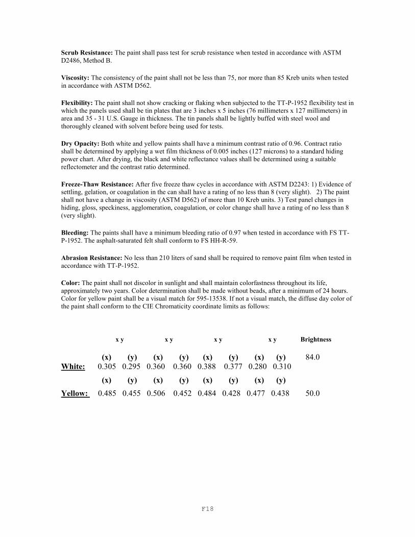
F18
Scrub Resistance: The paint shall pass test for scrub resistance when tested in accordance with ASTM
D2486, Method B.
Viscosity: The consistency of the paint shall not be less than 75, nor more than 85 Kreb units when tested
in accordance with ASTM D562.
Flexibility: The paint shall not show cracking or flaking when subjected to the TT-P-1952 flexibility test in
which the panels used shall be tin plates that are 3 inches x 5 inches (76 millimeters x 127 millimeters) in
area and 35 - 31 U.S. Gauge in thickness. The tin panels shall be lightly buffed with steel wool and
thoroughly cleaned with solvent before being used for tests.
Dry Opacity: Both white and yellow paints shall have a minimum contrast ratio of 0.96. Contract ratio
shall be determined by applying a wet film thickness of 0.005 inches (127 microns) to a standard hiding
power chart. After drying, the black and white reflectance values shall be determined using a suitable
reflectometer and the contrast ratio determined.
Freeze-Thaw Resistance: After five freeze thaw cycles in accordance with ASTM D2243: 1) Evidence of
settling, gelation, or coagulation in the can shall have a rating of no less than 8 (very slight). 2) The paint
shall not have a change in viscosity (ASTM D562) of more than 10 Kreb units. 3) Test panel changes in
hiding, gloss, speckiness, agglomeration, coagulation, or color change shall have a rating of no less than 8
(very slight).
Bleeding: The paints shall have a minimum bleeding ratio of 0.97 when tested in accordance with FS TT-
P-1952. The asphalt-saturated felt shall conform to FS HH-R-59.
Abrasion Resistance: No less than 210 liters of sand shall be required to remove paint film when tested in
accordance with TT-P-1952.
Color: The paint shall not discolor in sunlight and shall maintain colorfastness throughout its life,
approximately two years. Color determination shall be made without beads, after a minimum of 24 hours.
Color for yellow paint shall be a visual match for 595-13538. If not a visual match, the diffuse day color of
the paint shall conform to the CIE Chromaticity coordinate limits as follows:
x y x y x y x y Brightness
(x) (y) (x) (y) (x) (y) (x) (y) 84.0
White: 0.305 0.295 0.360 0.360 0.388 0.377 0.280 0.310
(x) (y) (x) (y) (x) (y) (x) (y)
Yellow: 0.485 0.455 0.506 0.452 0.484 0.428 0.477 0.438 50.0
F19
Liquid Calcium Chloride Anti-icing Agent
REFERENCE FILE Number 2007-3
Issued August 1, 2007
Scope: This reference file consists of the specification for Liquid Calcium Chloride Anti-icing Agent, which is to be used with Sodium Chloride for snow and ice control by the Connecticut Department of Transportation (Department).
The supplier shall furnish a Certified Test Report and Materials Certificate as detailed below for each batch delivered to the Department.
The Certified Test Report is a document containing a list of the dimensional, chemical, metallurgical, electrical and physical results obtained from a physical test of the materials involved, and shall certify that the materials being supplied meet the requirements of this specification. Such Report shall also include the following information:
(1) Description of materials
(2) Date of manufacture
(3) Date of testing
(4) Name of organization to which the material has been consigned, if applicable
(5) Quantity of material represented, such as batch, lot, group, etc.
(6) Means of identifying the consignment, such as label, marking, lot number, etc.
(7) Date and method of shipment
(8) Name of organization performing tests
The Certified Test Report shall be signed by a duly-authorized and responsible agent for the organization manufacturing the materials, and the signature must be notarized.
A Materials Certificate is a document certifying that the materials, components and equipment furnished conform to all requirements of this specification. Such Certificate shall also include the following information:
(1) Quantity of material represented, such as batch, lot, group, etc., and certified test report identification number representing materials being delivered
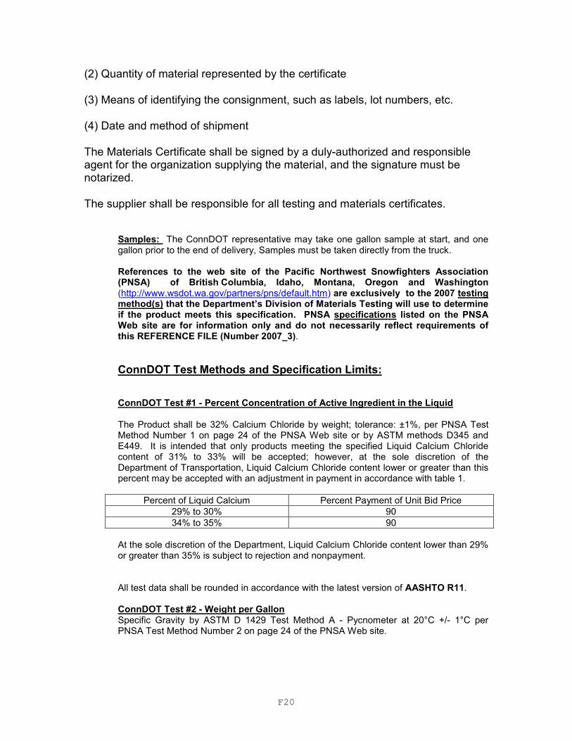
F20
(2) Quantity of material represented by the certificate
(3) Means of identifying the consignment, such as labels, lot numbers, etc.
(4) Date and method of shipment
The Materials Certificate shall be signed by a duly-authorized and responsible agent for the organization supplying the material, and the signature must be notarized.
The supplier shall be responsible for all testing and materials certificates.
Samples: The ConnDOT representative may take one gallon sample at start, and one gallon prior to the end of delivery, Samples must be taken directly from the truck. References to the web site of the Pacific Northwest Snowfighters Association (PNSA) of British Columbia, Idaho, Montana, Oregon and Washington (http://www.wsdot.wa.gov/partners/pns/default.htm) are exclusively to the 2007 testing method(s) that the Department’s Division of Materials Testing will use to determine if the product meets this specification. PNSA specifications listed on the PNSA Web site are for information only and do not necessarily reflect requirements of this REFERENCE FILE (Number 2007_3).
ConnDOT Test Methods and Specification Limits: ConnDOT Test #1 - Percent Concentration of Active Ingredient in the Liquid
The Product shall be 32% Calcium Chloride by weight; tolerance: ±1%, per PNSA Test Method Number 1 on page 24 of the PNSA Web site or by ASTM methods D345 and E449. It is intended that only products meeting the specified Liquid Calcium Chloride content of 31% to 33% will be accepted; however, at the sole discretion of the Department of Transportation, Liquid Calcium Chloride content lower or greater than this percent may be accepted with an adjustment in payment in accordance with table 1.
Percent of Liquid Calcium Percent Payment of Unit Bid Price
29% to 30% 90
34% to 35% 90
At the sole discretion of the Department, Liquid Calcium Chloride content lower than 29% or greater than 35% is subject to rejection and nonpayment. All test data shall be rounded in accordance with the latest version of AASHTO R11. ConnDOT Test #2 - Weight per Gallon Specific Gravity by ASTM D 1429 Test Method A - Pycnometer at 20°C +/- 1°C per PNSA Test Method Number 2 on page 24 of the PNSA Web site.
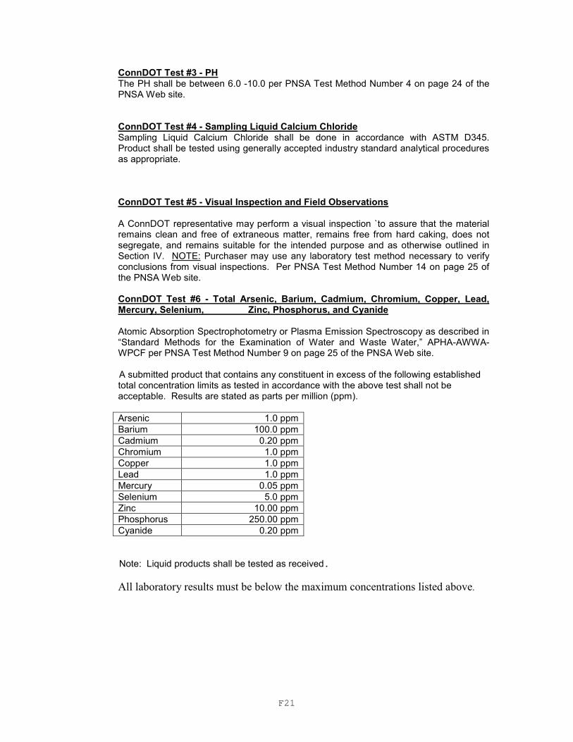
F21
ConnDOT Test #3 - PH The PH shall be between 6.0 -10.0 per PNSA Test Method Number 4 on page 24 of the PNSA Web site.
ConnDOT Test #4 - Sampling Liquid Calcium Chloride Sampling Liquid Calcium Chloride shall be done in accordance with ASTM D345. Product shall be tested using generally accepted industry standard analytical procedures as appropriate. ConnDOT Test #5 - Visual Inspection and Field Observations A ConnDOT representative may perform a visual inspection `to assure that the material remains clean and free of extraneous matter, remains free from hard caking, does not segregate, and remains suitable for the intended purpose and as otherwise outlined in Section IV. NOTE: Purchaser may use any laboratory test method necessary to verify conclusions from visual inspections. Per PNSA Test Method Number 14 on page 25 of the PNSA Web site.
ConnDOT Test #6 - Total Arsenic, Barium, Cadmium, Chromium, Copper, Lead, Mercury, Selenium, Zinc, Phosphorus, and Cyanide
Atomic Absorption Spectrophotometry or Plasma Emission Spectroscopy as described in “Standard Methods for the Examination of Water and Waste Water,” APHA-AWWA-WPCF per PNSA Test Method Number 9 on page 25 of the PNSA Web site.
A submitted product that contains any constituent in excess of the following established total concentration limits as tested in accordance with the above test shall not be acceptable. Results are stated as parts per million (ppm).
Arsenic 1.0 ppm
Barium 100.0 ppm
Cadmium 0.20 ppm
Chromium 1.0 ppm
Copper 1.0 ppm
Lead 1.0 ppm
Mercury 0.05 ppm
Selenium 5.0 ppm
Zinc 10.00 ppm
Phosphorus 250.00 ppm
Cyanide 0.20 ppm
Note: Liquid products shall be tested as received.
All laboratory results must be below the maximum concentrations listed above.
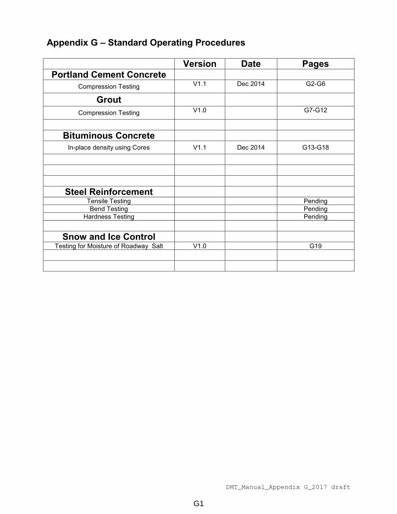
DMT_Manual_Appendix G_2017 draft
Appendix G – Standard Operating Procedures
Version Date Pages
Portland Cement Concrete
Compression Testing V1.1 Dec 2014 G2-G6
Grout
Compression Testing V1.0 G7-G12
Bituminous Concrete
In-place density using Cores V1.1 Dec 2014 G13-G18
Steel Reinforcement
Tensile Testing Pending
Bend Testing Pending
Hardness Testing Pending
Snow and Ice Control
Testing for Moisture of Roadway Salt V1.0 G19
G1

TINIUS-OLSEN COMPRESSION MACHINE Version 1.1 Standard Operating Procedure
John Giannini Mechanical & Electrical ___________________________ _ __ ____________________________ _ __
Supervisor of Laboratory/Workshop Type of hazards (mechanical, electrical,
chemical, biological or radiation)
Tinius-Olsen
Hydraulic Compression Tester
Equip. #68-3695 Room 150 _____________________________________________________ ____________________________ __
Name and Function of Lab/Project Location
Tinius-Olsen 400,000 Lbf Super “L” _______________________ _ ___ _________________________ ___ _____
Make Model
A. Introduction/Features
400,000 Lbf Capacity
Heavy-duty, ultra-stiff frame design permits testing of 6” X 12” and 4” X 8” concrete cylinders
Side and rear safety guards ensure operator safety
High-accuracy pressure transducer load weighing system
HP Compaq MXL31707H6 Controller
Wire safety cage to prevent debris from falling outside testing area.
B. Health and Safety Considerations
I. Safety devices required (e.g. machine guards, personal protective equipment, etc.)
SAFETY GOGGLES/GLASSES must be worn at all times in the lab. Prescription glasses can be
worn under the safety goggles.
HARD TOE BOOTS/SHOES must be worn at all times while handling cylinders.
II. General Safety
FOOD AND DRINK are not allowed in any laboratory.
Be aware of the specific hazards associated with each lab procedure.
Wear appropriate clothing and foot wear (NO OPEN-TOED SHOES).
Familiarize yourself with all emergency safety equipment (eyewash, fire alarm, fire extinguishers,
telephone).
Do not leave in-progress tests unattended.
Keep work areas Clean.
G2
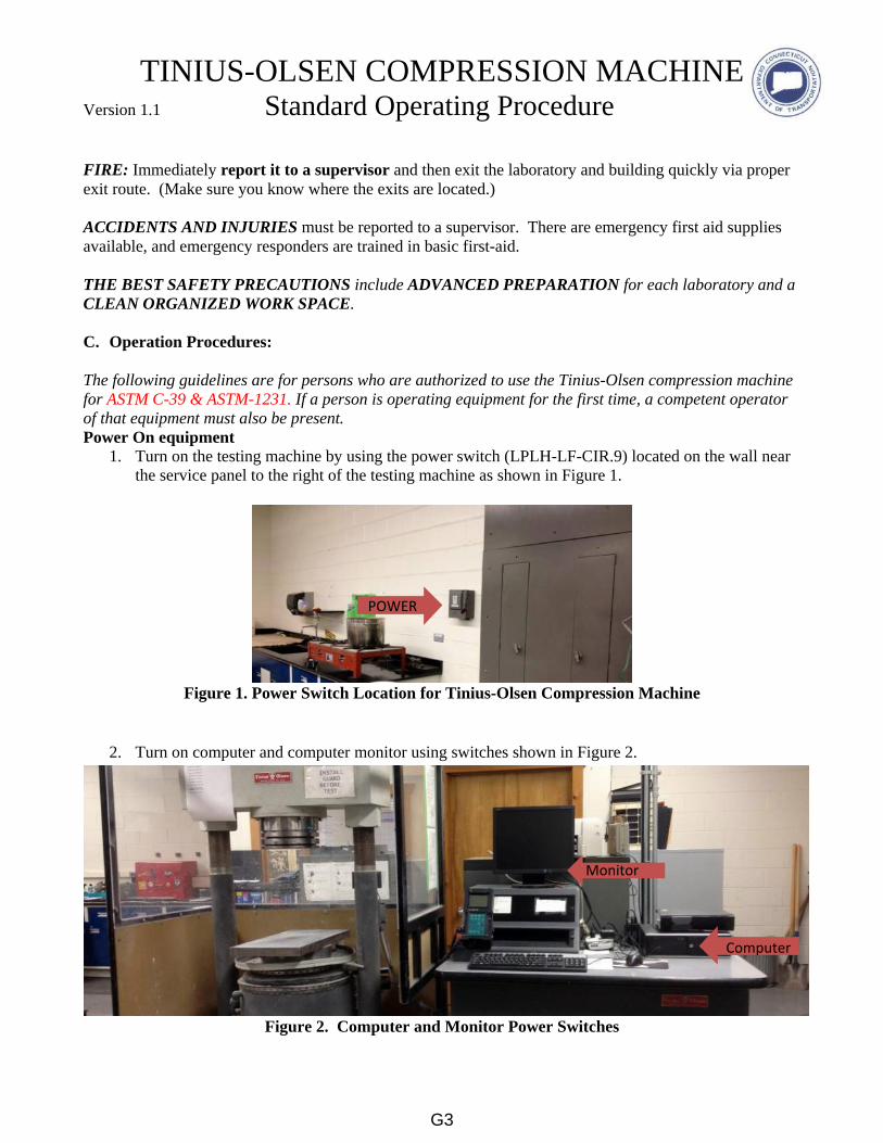
TINIUS-OLSEN COMPRESSION MACHINE Version 1.1 Standard Operating Procedure
FIRE: Immediately report it to a supervisor and then exit the laboratory and building quickly via proper
exit route. (Make sure you know where the exits are located.)
ACCIDENTS AND INJURIES must be reported to a supervisor. There are emergency first aid supplies
available, and emergency responders are trained in basic first-aid.
THE BEST SAFETY PRECAUTIONS include ADVANCED PREPARATION for each laboratory and a
CLEAN ORGANIZED WORK SPACE.
C. Operation Procedures:
The following guidelines are for persons who are authorized to use the Tinius-Olsen compression machine
for ASTM C-39 & ASTM-1231. If a person is operating equipment for the first time, a competent operator
of that equipment must also be present.
Power On equipment
1. Turn on the testing machine by using the power switch (LPLH-LF-CIR.9) located on the wall near
the service panel to the right of the testing machine as shown in Figure 1.
Figure 1. Power Switch Location for Tinius-Olsen Compression Machine
2. Turn on computer and computer monitor using switches shown in Figure 2.
Figure 2. Computer and Monitor Power Switches
A
POWER
Monitor
OWER
Computer
MonitorO
WER
G3

TINIUS-OLSEN COMPRESSION MACHINE Version 1.1 Standard Operating Procedure
Turn on hydraulic pump by pressing “Pump” button on handheld controller as shown in Figure 3. When
leaving the area of the machine for an extended period of time (10 minutes or more) shut off pump.
1) PUMP will appear on the display (let pump warm up for about 20 seconds)
2) Press “Return" button on handheld controller (the bottom compression plate will raise to
specific height)
Figure 3. Handheld Controller and Compression Plates
a. Using the computer mouse, Click on “Navigator” icon on the computer monitor
b. Using the steps below, check that the software is configured for the proper size cylinder.
1) go to file
2) load test setting
3) #8 for 6x12 or #9 for 4x8
Test Preparation
c. Review MAT-308 and enter project number and sample ID on “NEXT” tab
d. Check cylinder markings for concurrence with MAT-308
e. Type in or check appropriate cylinder size ( typically 6 or 4 inches) is displayed
f. Place test caps on bottom and top of cylinder. Caps are shown in Figure 4.
g. Properly place specimen (centered on bottom compression plate)
h. Place wire safety cage centered around specimen, close cage. Cage is shown in Figure 4.
A
Handheld Controller
A Bottom Compression Plate
A Top Compression Plate
G4

TINIUS-OLSEN COMPRESSION MACHINE Version 1.1 Standard Operating Procedure
Figure 4. Wire Safety Cage and Test Caps
3. Test Procedure
4”x8” cylinders
a. Double click on in top menu bar to raise base plate until the cylinder is located ⅛” from
top plate then click on the red STOP sign.
b. Click on the “LOAD ZERO” icon in top menu bar (handheld controller should show zero
load)
c. Click on TEST NOW button
d. Monitor the testing (Click on ABORT button if needed)
6”x12” cylinders
a. Click on the “LOAD ZERO” icon in top menu bar (handheld controller should show zero
load)
b. Click on TEST NOW button
c. Monitor the testing (Click on ABORT button if needed)
4. Documentation of Results
a. Observe how specimen broke and that no contact with wire safety cage was made.
b. Double check project number and sample ID, edit on “RESULTS” tab if needed.
c. Click on “ACCEPT” if no issues were observed. Click “DISCARD” if needed.
d. Record Total load and Load (PSI/Mpa) on Mat-308 from yellow highlighted information
at the bottom the window.
5. Remove crushed specimen
a. Open and remove wire safety cage
b. Discard crushed specimen in yellow rolling metal bin.
c. Clean bottom plate of any debris.
A$” X 6”
A
A Wire Safety Cage
4”x6” Caps
6”x12” Caps
G5

TINIUS-OLSEN COMPRESSION MACHINE Version 1.1 Standard Operating Procedure
6. To test another specimen;
e. Press the “NEXT” tab;
f. Return to step 2
7. Clean and shutdown
g. Properly close “Navigator” window by clicking on [X] in top right corner.
h. Click on “Start” icon in lower left corner and select “SHUTDOWN” from menu.
i. Turn pump off using handheld controller shown in Figure 3.
j. Switch test equipment off by using switch shown in Figure 1.
k. Clean floor, pan, and plates of any debris.
l. Record number of cylinders tested on Pad Usage Sheet in three ring binder located on test
console.
If you ever have any doubts or questions, ASK!
Emergency Contacts:
John Giannini, Supervising Engineer, 860-258-0324
Daniel Guzzo, Transportation Engineer III, 860-258-0339
Mark Brothwell, Transportation Engineer II, 860-258-0378
FIRE/AMBULANCE/SAFETY -Emergency Response, 9-911
G6
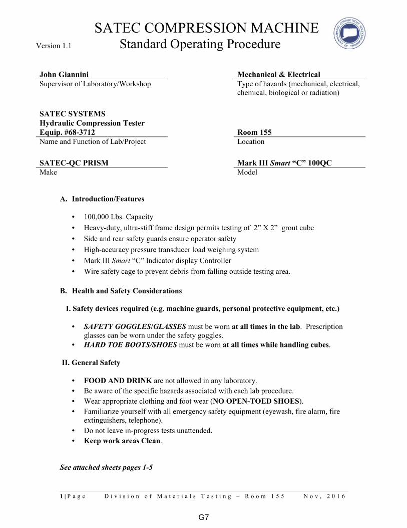
SATEC COMPRESSION MACHINE Version 1.1 Standard Operating Procedure
1 | P a g e D i v i s i o n o f M a t e r i a l s T e s t i n g – R o o m 1 5 5 N o v , 2 0 1 6
John Giannini Mechanical & Electrical
Supervisor of Laboratory/Workshop Type of hazards (mechanical, electrical,
chemical, biological or radiation)
SATEC SYSTEMS
Hydraulic Compression Tester
Equip. #68-3712 Room 155
Name and Function of Lab/Project Location
SATEC-QC PRISM Mark III Smart “C” 100QC
Make Model
A. Introduction/Features
• 100,000 Lbs. Capacity
• Heavy-duty, ultra-stiff frame design permits testing of 2” X 2” grout cube
• Side and rear safety guards ensure operator safety
• High-accuracy pressure transducer load weighing system
• Mark III Smart “C” Indicator display Controller
• Wire safety cage to prevent debris from falling outside testing area.
B. Health and Safety Considerations
I. Safety devices required (e.g. machine guards, personal protective equipment, etc.)
• SAFETY GOGGLES/GLASSES must be worn at all times in the lab. Prescription
glasses can be worn under the safety goggles.
• HARD TOE BOOTS/SHOES must be worn at all times while handling cubes.
II. General Safety
• FOOD AND DRINK are not allowed in any laboratory.
• Be aware of the specific hazards associated with each lab procedure.
• Wear appropriate clothing and foot wear (NO OPEN-TOED SHOES).
• Familiarize yourself with all emergency safety equipment (eyewash, fire alarm, fire
extinguishers, telephone).
• Do not leave in-progress tests unattended.
• Keep work areas Clean.
See attached sheets pages 1-5
G7
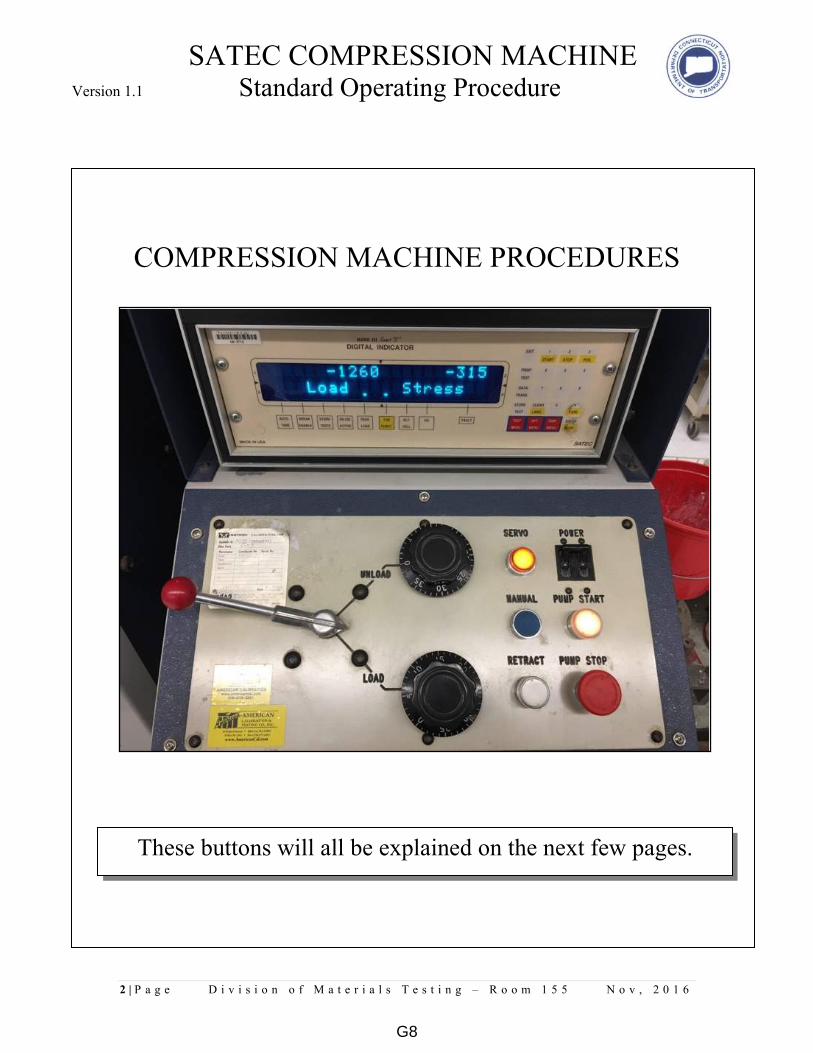
SATEC COMPRESSION MACHINE Version 1.1 Standard Operating Procedure
2 | P a g e D i v i s i o n o f M a t e r i a l s T e s t i n g – R o o m 1 5 5 N o v , 2 0 1 6
COMPRESSION MACHINE PROCEDURES
These buttons will all be explained on the next few pages.
G8

SATEC COMPRESSION MACHINE Version 1.1 Standard Operating Procedure
3 | P a g e D i v i s i o n o f M a t e r i a l s T e s t i n g – R o o m 1 5 5 N o v , 2 0 1 6
Step 1
Flip switch for power.
Step 2
Turn knob clockwise
till it pops up.
Step 3
Press the button to turn on
the pumps.
G9

SATEC COMPRESSION MACHINE Version 1.1 Standard Operating Procedure
4 | P a g e D i v i s i o n o f M a t e r i a l s T e s t i n g – R o o m 1 5 5 N o v , 2 0 1 6
Total Load
These units are reading in metric.
PSI
Step 6
Press the TARE
button to switch
modes.
Step 4
Press the MODE
button once to switch
what’s on the display.
Step 5
Press the LANG
button to switch
between metric and
english.
Step 7 Make sure the arrow
shows up each time you
break a cube in the
AUTO TARE box.
G10
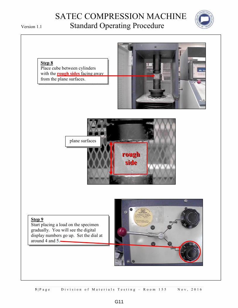
SATEC COMPRESSION MACHINE Version 1.1 Standard Operating Procedure
5 | P a g e D i v i s i o n o f M a t e r i a l s T e s t i n g – R o o m 1 5 5 N o v , 2 0 1 6
Step 8 Place cube between cylinders
with the rough sides facing away
from the plane surfaces.
Step 9 Start placing a load on the specimen
gradually. You will see the digital
display numbers go up. Set the dial at
around 4 and 5.
plane surfaces
rrrooouuuggghhh
sssiiidddeee
G11

SATEC COMPRESSION MACHINE Version 1.1 Standard Operating Procedure
6 | P a g e D i v i s i o n o f M a t e r i a l s T e s t i n g – R o o m 1 5 5 N o v , 2 0 1 6
These are procedures that will ensure the proper methods of testing
cement cubes per ASTM C109.
Step 10 Push the servo button. It will then start
placing a load on the specimen
gradually. You will see the digital
display numbers go up.
Total Load
Step 11 When you notice the numbers
slowing down or stress cracks
on the cube itself that means it’s
reached its breaking point.
PSI
G12
HANDLING AND TESTING BITUMINOUS
CONCRETE CORE SAMPLES FOR IN-PLACE
DENSITY DETERMINATION Version 1.1 Standard Operating Procedure
Eliana Carlson Mechanical & Electrical ___________________________ _ __ ____________________________ _ __
Supervisor of Laboratory/Workshop Type of hazards (mechanical, electrical,
chemical, biological or radiation)
Handling and Testing Hot Mix
Cores for Density Determination Rooms 162 and 159 _____________________________________________________ ____________________________ __
Name and Function of Lab/Project Location
Various Various _______________________ _ ___ _________________________ ___ _____
Make Model
A. Introduction/Features
Procedures to be followed for the in-place density of bituminous concrete mixtures by testing cores
samples
Handling of the bituminous concrete core samples include:
o Receiving core samples (chain of custody)
o Organization
Testing of the bituminous concrete core samples include:
o Saw cutting core samples
o Drying core samples
o Testing for bulk specific gravity
o Reporting
o Core sample retention and disposal
Equipment:
o 5 Vacuum drying apparatus located in room 162:
Make: Instrotek
Model: CoreDry
o 1 Automatic vacuum sealing apparatus located in Room 162
Make: Instrotek
Model: CoreLok
o 2 Radial cutting table saws located in Room 159
Make: Nuova Mondial Mec
Model: Manta ED 120
G13

HANDLING AND TESTING BITUMINOUS
CONCRETE CORE SAMPLES FOR IN-PLACE
DENSITY DETERMINATION Version 1.1 Standard Operating Procedure
B. Health and Safety Considerations
I. Safety devices required (e.g. machine guards, personal protective equipment, etc.)
SAFETY GOGGLES/GLASSES must be worn when operating the table saw. Prescription glasses
can be worn under the safety goggles.
SAFETY EAR PROTECTION must be worn when operating the table saw.
The operator shall keep all body parts outside the MACHINE GUARDS when operating the table
saw
HARD TOE BOOTS/SHOES must be worn at all times in the laboratory.
II. General Safety
FOOD AND DRINK are not allowed in any laboratory.
Be aware of the specific hazards associated with each laboratory procedure.
Wear appropriate clothing and foot wear (NO OPEN-TOED SHOES).
Familiarize yourself with all emergency safety equipment (eyewash, fire alarm, fire extinguishers,
telephone).
Do not leave in-progress tests unattended.
Keep work areas Clean.
FIRE: Immediately report it to a supervisor and then exit the laboratory and building quickly via proper
exit route. (Make sure you know where the exits are located.)
ACCIDENTS AND INJURIES must be reported to a supervisor. There are emergency first aid supplies
available, and emergency responders are trained in basic first-aid.
THE BEST SAFETY PRECAUTIONS include ADVANCED PREPARATION for each laboratory and a
CLEAN ORGANIZED WORK SPACE.
C. Equipment Maintenance
All maintenance operations shall follow the corresponding operator’s manual.
CoreDry Maintenance:
- Change the vacuum pump oil (InstroTek part number 1520137) after 80 hours of use. A software
indicator will prompt you to do so. Keep the maintenance records updated in the corresponding
calibration and maintenance book.
- Change your Tank Filters (InstroTek part number 1009012) every 1 to 2 months. Keep the
maintenance records updated in the corresponding calibration and maintenance book.
G14
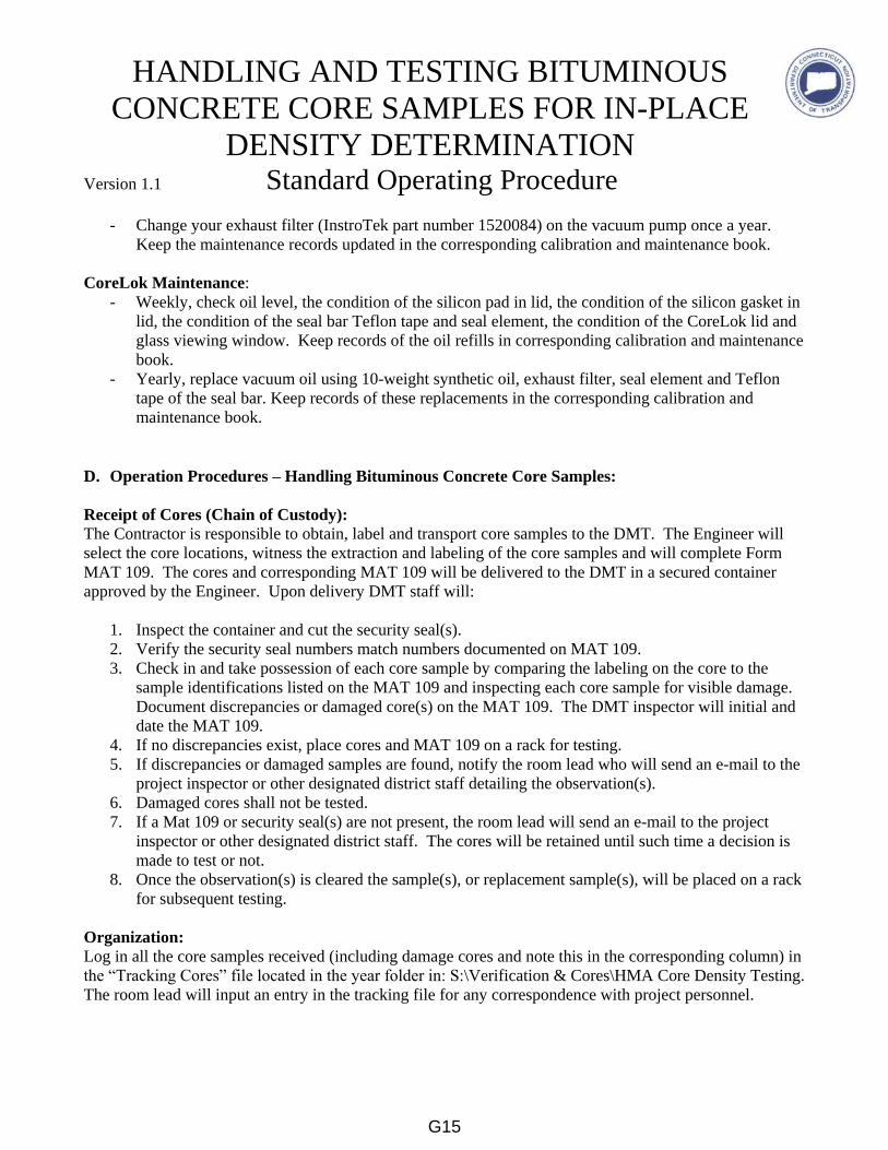
HANDLING AND TESTING BITUMINOUS
CONCRETE CORE SAMPLES FOR IN-PLACE
DENSITY DETERMINATION Version 1.1 Standard Operating Procedure
- Change your exhaust filter (InstroTek part number 1520084) on the vacuum pump once a year.
Keep the maintenance records updated in the corresponding calibration and maintenance book.
CoreLok Maintenance:
- Weekly, check oil level, the condition of the silicon pad in lid, the condition of the silicon gasket in
lid, the condition of the seal bar Teflon tape and seal element, the condition of the CoreLok lid and
glass viewing window. Keep records of the oil refills in corresponding calibration and maintenance
book.
- Yearly, replace vacuum oil using 10-weight synthetic oil, exhaust filter, seal element and Teflon
tape of the seal bar. Keep records of these replacements in the corresponding calibration and
maintenance book.
D. Operation Procedures – Handling Bituminous Concrete Core Samples:
Receipt of Cores (Chain of Custody):
The Contractor is responsible to obtain, label and transport core samples to the DMT. The Engineer will
select the core locations, witness the extraction and labeling of the core samples and will complete Form
MAT 109. The cores and corresponding MAT 109 will be delivered to the DMT in a secured container
approved by the Engineer. Upon delivery DMT staff will:
1. Inspect the container and cut the security seal(s).
2. Verify the security seal numbers match numbers documented on MAT 109.
3. Check in and take possession of each core sample by comparing the labeling on the core to the
sample identifications listed on the MAT 109 and inspecting each core sample for visible damage.
Document discrepancies or damaged core(s) on the MAT 109. The DMT inspector will initial and
date the MAT 109.
4. If no discrepancies exist, place cores and MAT 109 on a rack for testing.
5. If discrepancies or damaged samples are found, notify the room lead who will send an e-mail to the
project inspector or other designated district staff detailing the observation(s).
6. Damaged cores shall not be tested.
7. If a Mat 109 or security seal(s) are not present, the room lead will send an e-mail to the project
inspector or other designated district staff. The cores will be retained until such time a decision is
made to test or not.
8. Once the observation(s) is cleared the sample(s), or replacement sample(s), will be placed on a rack
for subsequent testing.
Organization:
Log in all the core samples received (including damage cores and note this in the corresponding column) in
the “Tracking Cores” file located in the year folder in: S:\Verification & Cores\HMA Core Density Testing.
The room lead will input an entry in the tracking file for any correspondence with project personnel.
G15
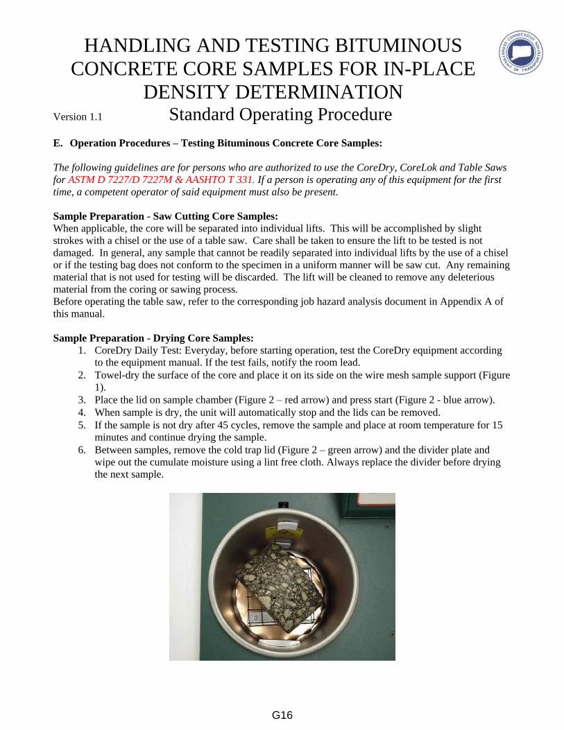
HANDLING AND TESTING BITUMINOUS
CONCRETE CORE SAMPLES FOR IN-PLACE
DENSITY DETERMINATION Version 1.1 Standard Operating Procedure
E. Operation Procedures – Testing Bituminous Concrete Core Samples:
The following guidelines are for persons who are authorized to use the CoreDry, CoreLok and Table Saws
for ASTM D 7227/D 7227M & AASHTO T 331. If a person is operating any of this equipment for the first
time, a competent operator of said equipment must also be present.
Sample Preparation - Saw Cutting Core Samples:
When applicable, the core will be separated into individual lifts. This will be accomplished by slight
strokes with a chisel or the use of a table saw. Care shall be taken to ensure the lift to be tested is not
damaged. In general, any sample that cannot be readily separated into individual lifts by the use of a chisel
or if the testing bag does not conform to the specimen in a uniform manner will be saw cut. Any remaining
material that is not used for testing will be discarded. The lift will be cleaned to remove any deleterious
material from the coring or sawing process.
Before operating the table saw, refer to the corresponding job hazard analysis document in Appendix A of
this manual.
Sample Preparation - Drying Core Samples:
1. CoreDry Daily Test: Everyday, before starting operation, test the CoreDry equipment according
to the equipment manual. If the test fails, notify the room lead.
2. Towel-dry the surface of the core and place it on its side on the wire mesh sample support (Figure
1).
3. Place the lid on sample chamber (Figure 2 – red arrow) and press start (Figure 2 - blue arrow).
4. When sample is dry, the unit will automatically stop and the lids can be removed.
5. If the sample is not dry after 45 cycles, remove the sample and place at room temperature for 15
minutes and continue drying the sample.
6. Between samples, remove the cold trap lid (Figure 2 – green arrow) and the divider plate and
wipe out the cumulate moisture using a lint free cloth. Always replace the divider before drying
the next sample.
G16
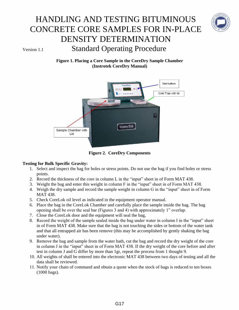
HANDLING AND TESTING BITUMINOUS
CONCRETE CORE SAMPLES FOR IN-PLACE
DENSITY DETERMINATION Version 1.1 Standard Operating Procedure
Figure 1. Placing a Core Sample in the CoreDry Sample Chamber
(Instrotek CoreDry Manual)
Figure 2. CoreDry Components
Testing for Bulk Specific Gravity:
1. Select and inspect the bag for holes or stress points. Do not use the bag if you find holes or stress
points.
2. Record the thickness of the core in column L in the “input” sheet in of Form MAT 438.
3. Weight the bag and enter this weight in column F in the “input” sheet in of Form MAT 438.
4. Weigh the dry sample and record the sample weight in column G in the “input” sheet in of Form
MAT 438.
5. Check CoreLok oil level as indicated in the equipment operator manual.
6. Place the bag in the CoreLok Chamber and carefully place the sample inside the bag. The bag
opening shall be over the seal bar (Figures 3 and 4) with approximately 1” overlap.
7. Close the CoreLok door and the equipment will seal the bag,
8. Record the weight of the sample sealed inside the bag under water in column I in the “input” sheet
in of Form MAT 438. Make sure that the bag is not touching the sides or bottom of the water tank
and that all entrapped air has been remove (this may be accomplished by gently shaking the bag
under water).
9. Remove the bag and sample from the water bath, cut the bag and record the dry weight of the core
in column J in the “input” sheet in of Form MAT 438. If the dry weight of the core before and after
test in column J and G differ by more than 1gr, repeat the process from 1 thought 9.
10. All weights of shall be entered into the electronic MAT 438 between two days of testing and all the
data shall be reviewed.
11. Notify your chain of command and obtain a quote when the stock of bags is reduced to ten boxes
(1000 bags).
G17
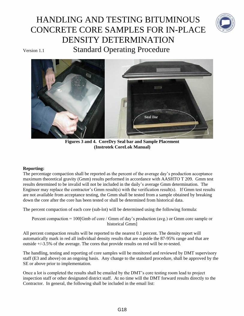
HANDLING AND TESTING BITUMINOUS
CONCRETE CORE SAMPLES FOR IN-PLACE
DENSITY DETERMINATION Version 1.1 Standard Operating Procedure
Figures 3 and 4. CoreDry Seal bar and Sample Placement
(Instrotek CoreLok Manual)
Reporting:
The percentage compaction shall be reported as the percent of the average day’s production acceptance
maximum theoretical gravity (Gmm) results performed in accordance with AASHTO T 209. Gmm test
results determined to be invalid will not be included in the daily’s average Gmm determination. The
Engineer may replace the contractor’s Gmm result(s) with the verification result(s). If Gmm test results
are not available from acceptance testing, the Gmm shall be tested from a sample obtained by breaking
down the core after the core has been tested or shall be determined from historical data.
The percent compaction of each core (sub-lot) will be determined using the following formula:
Percent compaction = 100[Gmb of core / Gmm of day’s production (avg.) or Gmm core sample or
historical Gmm]
All percent compaction results will be reported to the nearest 0.1 percent. The density report will
automatically mark in red all individual density results that are outside the 87-95% range and that are
outside +/-3.5% of the average. The cores that provide results on red will be re-tested.
The handling, testing and reporting of core samples will be monitored and reviewed by DMT supervisory
staff (E3 and above) on an ongoing basis. Any change to the standard procedure, shall be approved by the
SE or above prior to implementation.
Once a lot is completed the results shall be emailed by the DMT’s core testing room lead to project
inspection staff or other designated district staff. At no time will the DMT forward results directly to the
Contractor. In general, the following shall be included in the email list:
G18
HANDLING AND TESTING BITUMINOUS
CONCRETE CORE SAMPLES FOR IN-PLACE
DENSITY DETERMINATION Version 1.1 Standard Operating Procedure
Construction projects; Project Engineer, Project Inspector, District email, DMT chain of command.
VIP and other Maintenance Projects; District Planners and/or other designated staff, DMT chain of
command.
Municipal Projects; Muni Team leader, Muni team inspector (if known), muni MAT 100 email,
DMT chain of command.
Report Form: Form MAT 438 or other form approved by the DMT.
Core Sample Retention and Disposal:
After the specific gravity testing has been completed and reviewed by the room lead, store the tested core in
the back hall rack for a two-week period. After two weeks, dispose the cores in the HMA recycling bin
located in the back dock. In general cores that are below the minimum acceptable density (negative
adjustment range) should be retained for a slightly longer period to allow for inspection by others. Any lot
that is remove and replace will be retained until such time it is determined they are no longer needed.
If you ever have any doubts or questions, ASK!
Emergency Contacts:
Eliana Carlson, Supervising Engineer, 860-258-0325
David Howley, Transportation Engineer III, 860-258-0350
Shane St. Lauren, Transportation Technician III, 860-258-03??
FIRE/AMBULANCE/SAFETY -Emergency Response, 9-911
G19
Division of Materials Testing
Connecticut Department of Transportation
G20
Division of Materials Testing P a g e | 1
Connecticut Department of Transportation
Why is roadway salt tested for moisture content?
• Roadway salt is paid for based on gross weight.
• Specifications allow 3% moisture content for full payment.
• Weight of water in excess of 3% is deducted from payment by contract administrator (Purchasing).
• Salt with excess moisture may clump and freeze, making handling difficult.
Scale Inspection/Check
• Scales must be labeled with current calibration date.
• Scale must show same reading (within 0.1 gram) when weighing the same reference weight.
• These steps must be performed before each test or if a scale has been moved.
G21
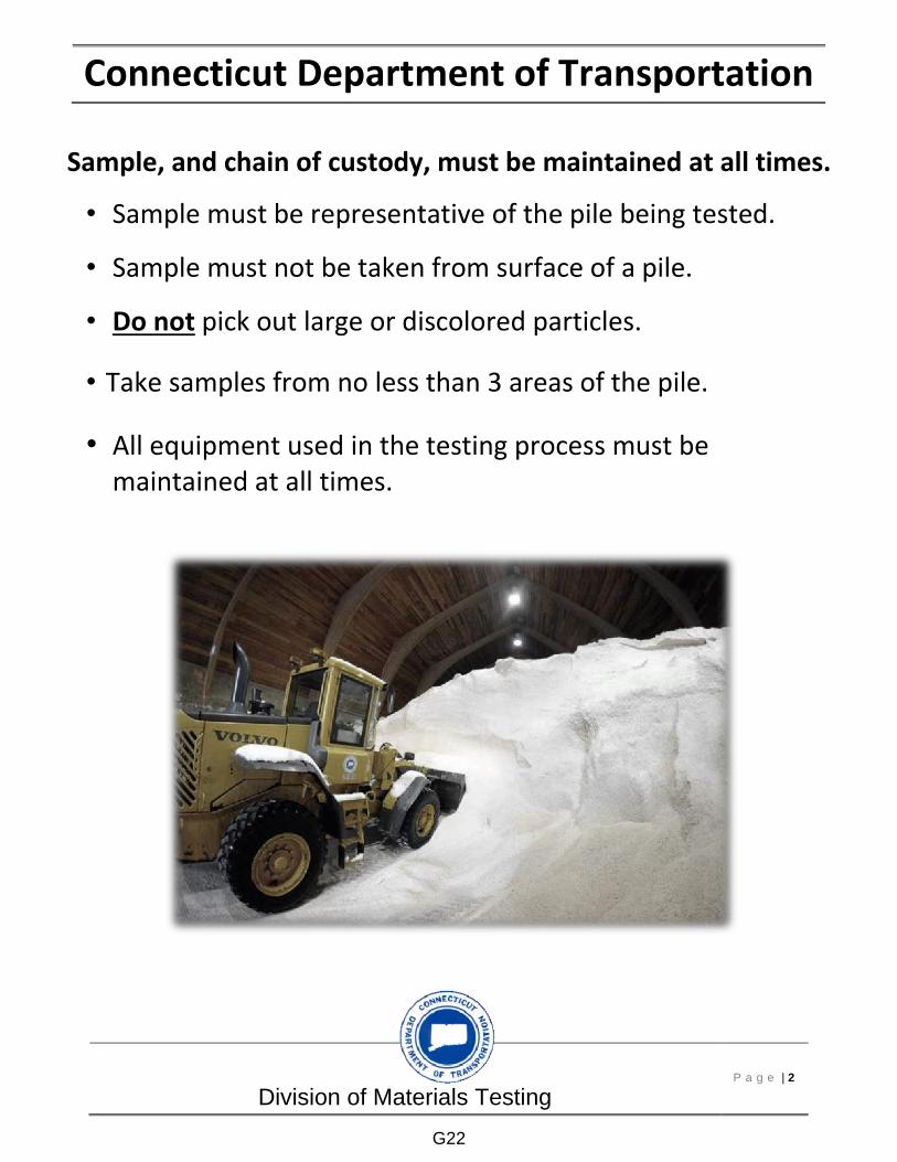
Division of Materials Testing P a g e | 2
Connecticut Department of Transportation
Sample, and chain of custody, must be maintained at all times.
• Sample must be representative of the pile being tested.
• Sample must not be taken from surface of a pile.
• Do not pick out large or discolored particles.
• Take samples from no less than 3 areas of the pile.
• All equipment used in the testing process must be maintained at all times.
G22

Division of Materials Testing P a g e | 3
Connecticut Department of Transportation Equipment Needed:
• Oven
• Calibrated Digital Scale
• Sampling Containers/Sampling Bag
• Shovel / Scoop / Sample Thief
G23
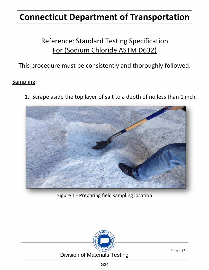
Division of Materials Testing P a g e | 4
Connecticut Department of Transportation
Reference: Standard Testing Specification For (Sodium Chloride ASTM D632)
This procedure must be consistently and thoroughly followed.
Sampling:
1. Scrape aside the top layer of salt to a depth of no less than 1 inch.
Figure 1 - Preparing field sampling location
G24

Division of Materials Testing P a g e | 5
Connecticut Department of Transportation
2. Take approximately 500 g of material to a depth of six inches. • Repeat steps 1 and 2 at two locations, no less than five feet
from each other.
Figure 2 - Sampling
3. Place the three samples in a sample bag.
Figure 3 - Filling field sample bag
G25

Division of Materials Testing P a g e | 6
Connecticut Department of Transportation
4. Sample bag must be closed tightly while transporting field sample.
Figure 4 – Securing sample bag
5. The field sample must be reduced to a minimum of 300 grams test sample using sample splitter.
Figure 5 - Sample splitter
6. Determine the mass of the test sample and a metal container of
stable shape and weight, using a scale.
Figure 6 - Scale
G26
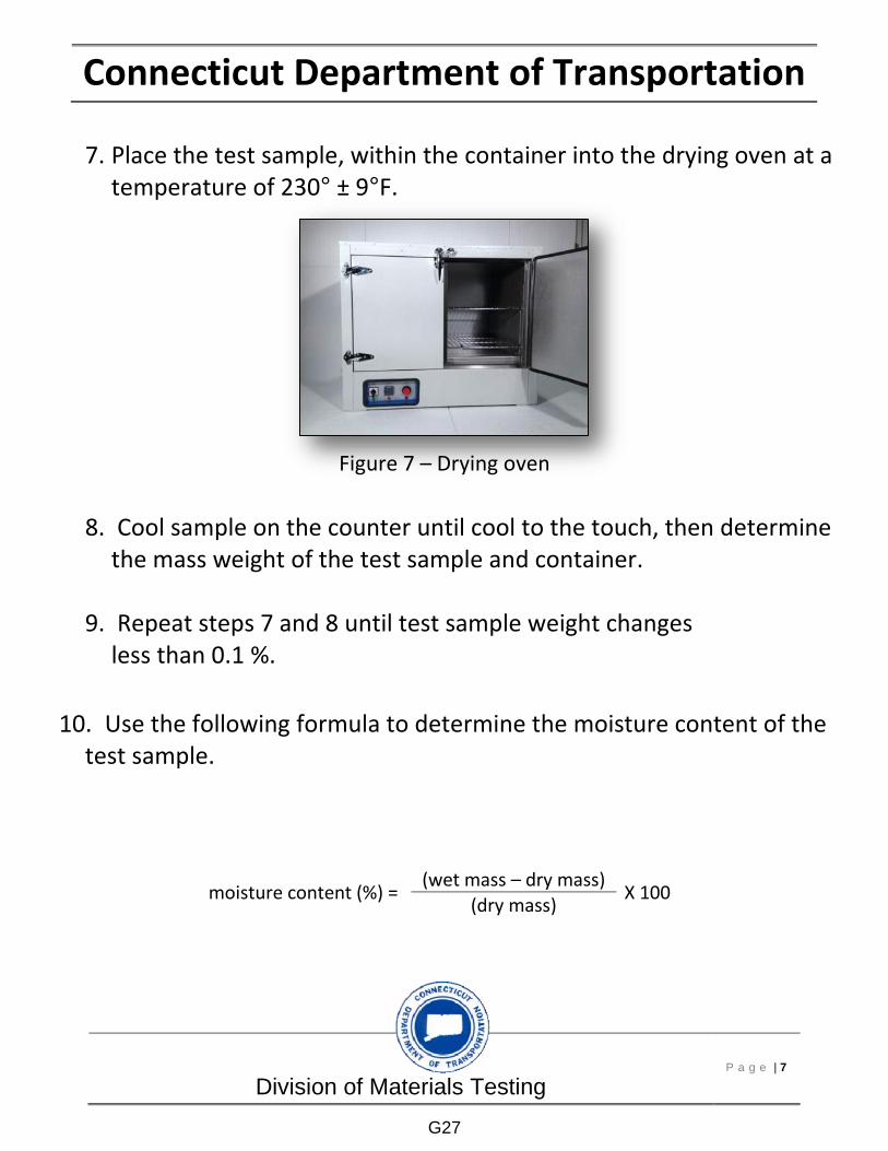
Division of Materials Testing P a g e | 7
Connecticut Department of Transportation
7. Place the test sample, within the container into the drying oven at a temperature of 230° ± 9°F.
Figure 7 – Drying oven
8. Cool sample on the counter until cool to the touch, then determine the mass weight of the test sample and container.
9. Repeat steps 7 and 8 until test sample weight changes
less than 0.1 %.
10. Use the following formula to determine the moisture content of the test sample.
moisture content (%) = (wet mass – dry mass)
X 100 (dry mass)
G27

Division of Materials Testing P a g e | 8
Connecticut Department of Transportation
References Photos:
1. Oven – “Clarkson Laboratory”, • http://store.clarksonlab.com/O4325-B.aspx
2. Digital Scale – “Scale Palace”,
• https://scalepalace.com/index.php?main_page=index&manufacturers_id=6&sort=20a&page=3
3. Scoop – “Cole-Palmer”,
• http://www.coleparmer.com/Product/Stainless_Steel_Scoop_201_Grade_5_oz_1_each/EW-07205-01
4. Sample Thief – Wilkey Industries, Inc”,
• http://www.wilkeyindustries.com/sample-probe.php
5. CTDOT Salt Shed – “Ctpost”,
• http://www.ctpost.com/local/article/Storms-draining-road-salt-supplies-straining-5222298.php
All other photos are property of CTDOT
G28

H1
Index Admixtures for Portland Cement Concrete, 29
Aggregate Degradation, Resistance to, 20
Aggregate Soundness, 21 Aggregate, Bulk Density, 21 Aggregate, Flat and/or Elongated Particles, 21
Aggregate, Fractured Particles, 21 Aggregate, Inorganic Impurities in., 21
Aggregate, Mechanical Analysis for HMA, 30 Aggregate, Reducing Sample size, 20 Aggregate, Sampling, 20, 23 Aggregate, Sieve analysis, 20 Aggregate, Specific Gravity and Absorption, 21
Aggregate, Total Evaporative Moisture Content, 21
Aggregate, Voids in, 21 Aluminum, Castings, 14 Aluminum, fittings, 14 Aluminum, tubing, 14 AMRL Certification Document, 36 Anchor Bolts, Steel, 16 Anchorages, Cable Guide Rail, 16 Asphalt, Emulsified, 18 Asphaltic Plug Joint, 19 Bearing Pads, 16 Bearing Pads, Elastomeric, 16 Bearing plates, bronze or copper, 16
Bolts, Anchor, 16 Bolts, High strength Steel, 17 Bronze Bearing plates, 16 Bronze Expansion plates, 16 Bulk Specific Gravity of HMA, 31 Cable Guide Railing, 16 Calcium Chloride, 9 Castings, Metal, 14 Cement, 13 Chain Link Fence, 14 Compression Seals, Elastomeric, 14 Concrete Block, 14 Concrete Brick, 14 Concrete Mix Design, 12 Concrete Pavement, Transverse joints, 13
Concrete Pipe inspection, 23 Concrete, Admixtures, 29 Concrete, Gravimetric test, 29 Concrete, Inspection of batch plants and truck mixers), 29
Concrete, Pipe reinforced, 23 Copper Bearing plates, 16
Copper Expansion plates, 16 Evaporative Moisture Content, Aggregate, 21
Expansion plates, Bronze or Copper, 16
Fence, Chain Link, 14 Fence, Wire, 15 Fertilizer, 9 Geotextiles, 15 Glass Beads/Spheres, 9 Grass, 9 Grout, non-shrink, non-staining, 12 HMA Plants, Annual Qualification, 30 HMA Sampling, 30 HMA, Gyratory Specimens, 31 HMA, Mix Design Submittal and JMF Change
Procedure, 32 HMA, New and Existing Mixes, 32 HMA, Particle Coating, 31 HMA, Personnel Assignment, 30 HMA, Plant Inspector, 32 HMA, Production Inspection, 32 HMA, Resistance to Moisture Induced Damage, 35
HMA, Verification Testing, 33 HMA, VMA and Correction Factor, 31 HMA, Volumetric and Specific Gravity, 35 Hot Mix Asphalt, 18 Illumination, Highway, 17 Independent Assessment/Verification Program, 37
Joint Sealants, 13 Joints, Transverse for Concrete Pavement, 13
L.A. Abrasion, 20 Limestone, 10 Magnesium Sulfate, 21 Markers, Object, 18 Masonry Facing, 21 Maximum Specific Gravity of HMA, 32 Metal, Castings, 14 Mulch, Wood Cellulose, 10 Nuclear Density of Soils, 35 Object Markers, 18 Organizational Chart, 3 Overview, Division of Materials Testing, 2
Paint, Pvmnt Marking 15 Min., 8 Paint, Trafffic 3 Min., 8 Peat, 9 Perforated Concrete Pipe, 10 Performance Graded Asphalt Binder (PGAB), 35
H2
Piles, Steel, 17 Pipe, Concrete, 23 Pipe, Concrete Perforated, 10 Pipe, Concrete plain, 10 Pipe, plastic, 11 Pipe, polyethylene, 11 Pipe, PVC, 11 Pipe, Steel, Welded and Seamless, 11, 12
Plain Concrete Pipe, 10 Plastic Flow of HMA, 31 Portland Cement, 12, 13 Precast Concrete Drainage Items, 11 Precast Concrete for drainage structures, 11
Precast Concrete Structural Members, 13
Precast Concrete Structural Members, Fabrication Inspection, 13
Purpose, 1 Quality Acceptance Section (QAC), 4 Quality Assurance Section, 5 Rock Salt, 9 Sampling, Care in, 22
Sand Blast Debris, 8 Sealers, Hot Poured, 14 Seed, 9 Sheet Piling, Steel, 17 Signals, Traffic Control, 17 Signs, 18 Sod, 10 Sodium Chloride, 9 Steel Sheet Piling, 17 Steel, Anchor Bolts, 16 Steel, Bar Mat, 12 Steel, Coatings, 8 Steel, High strength bolts, 17 Steel, Prestressing, 13 Steel, Reinforcing Bar, 12 Steel, Structural, 17 Steel, Welded Wire Fabric, 12 Steel, Wire, 12 Top Soil, 10 Washing, Material finer than #200 Sieve, 20 Water, 9 Waterproofing, Membrane, 19 Welding, Filler metal, 17 Wire Fence, 15 Wood Fiber Mulch, 10
Related Documents