Stanford University Gravity Probe B Program P0213D GRAVITY PROBE B PROCEDURE FOR SCIENCE MISSION DEWAR CONNECT VACUUM MODULE / PUMP ON SMD VACUUM SHELL P0213 REV. D ECO 1403 March 13, 2003 Revised by Checked by ______________________Date_______ ______________________Date_______ Ned Calder Jim Maddocks Cryogenic Test Cryogenic Test Approvals: ______________________Date_______ ______________________Date_______ Dorrene Ross Harv Moskowitz Quality Assurance LM Safety ______________________Date_______ ______________________Date_______ Robert Brumley Mike Taber Payload Technical Manager Payload Test Director

Welcome message from author
This document is posted to help you gain knowledge. Please leave a comment to let me know what you think about it! Share it to your friends and learn new things together.
Transcript

Stanford University Gravity Probe B Program P0213D
GRAVITY PROBE B PROCEDURE FOR
SCIENCE MISSION DEWAR
CONNECT VACUUM MODULE / PUMP ON SMD VACUUM SHELL
P0213 REV. D
ECO 1403
March 13, 2003
Revised by Checked by
______________________Date_______ ______________________Date_______ Ned Calder Jim Maddocks Cryogenic Test Cryogenic Test Approvals: ______________________Date_______ ______________________Date_______ Dorrene Ross Harv Moskowitz Quality Assurance LM Safety ______________________Date_______ ______________________Date_______ Robert Brumley Mike Taber Payload Technical Manager Payload Test Director

Connect Vacuum Module / Pump on SMD Vacuum Shell Gravity Probe B Program P0213c
Page i
REVISION RECORD
REVISION ECO PAGES DATE
A 733 Update procedure based on experience of performing operations
1/27/98
B 1092 Changed title to reflect procedure contents more accurately. Change title to: Connect Vacuum Module / Pump on SMD Vacuum Shell.
Section A – Revised scope to reflect content of procedure more accurately.
Section B – Divided into two sections, addressing safety issues (new Section B) and test personnel (new Section D). Reorganized safety paragraphs into: hazards, mitigation, injuries. Content of both new sections essentially unchanged.
Added Quality Assurance Section (new Section C)
Section C, D, and E – Consolidated all requirements into new Section E entitled Requirements. Added Configuration requirements, GSE/SMD interface requirements, alarm setup requirements, vacuum requirements, and non-flight hardware requirements.
Added sections to verify QA notification, verify initial configuration, ensure DAS and liquid-level alarms properly set.
Added capability to begin from three possible initial configurations and end in one of three final configurations.
5/30/00
C 1295 Added data sheet (Table 1) and minor redlines. 8/9/01
D 1403 Added optional section to perform leak check of all dewar seals
Updated figures
Add pre/post checklists
3/14/03

Connect Vacuum Module / Pump on SMD Vacuum Shell Gravity Probe B Program P0213c
Page ii
Table of Contents
A. SCOPE ..............................................................................................................................1
B. SAFETY.............................................................................................................................1 B.1. Potential Hazards ......................................................................................................1 B.2. Mitigation of Hazards.................................................................................................2 B.3. Injuries.......................................................................................................................2
C. QUALITY ASSURANCE.....................................................................................................2 C.1. QA Notification ..........................................................................................................2 C.2. Red-line Authority......................................................................................................2 C.3. Discrepancies............................................................................................................3
D. TEST PERSONNEL...........................................................................................................3 D.1. Personnel Responsibilities ........................................................................................3 D.2. Personnel Qualifications............................................................................................3 D.3. Qualified Personnel ...................................................................................................3
REQUIREMENTS .......................................................................................................................4 D.4. Electrostatic Discharge Requirements.......................................................................4 D.5. Lifting Operation Requirements.................................................................................4 D.6. Hardware/Software Requirements ............................................................................4 D.7. Instrument Pretest Requirements..............................................................................5 D.8. Configuration Requirements......................................................................................6 D.9. Optional Non-flight Configurations ............................................................................7
E. REFERENCE DOCUMENTS .............................................................................................8 E.1. Drawings ...................................................................................................................8 E.2. Supporting documentation ........................................................................................8 E.3. Additional Procedures ...............................................................................................8
F. OPERATIONS....................................................................................................................9 F.1. Verify Appropriate QA Notification.............................................................................9 F.2. Verify Configuration Requirements............................................................................9 F.3. Connect High-Vacuum Pumping Line to Vacuum Module.......................................11 F.4. Connect SV-14 operator to SMD Pump Out Port at SV-14 .....................................11 F.5. Connect High-Vacuum Pumping Line to Dewar ......................................................11 F.6. Evacuate Pumping Line up to Closed Valve SV-14. ...............................................12 F.7. Leak Test High-Vacuum System up to Closed Valve SV-14 ...................................14 F.8. Place System in Final Configuration........................................................................15 F.9. Establish Final Alarm Configuration ........................................................................17

Connect Vacuum Module / Pump on SMD Vacuum Shell Gravity Probe B Program P0213c
Page iii
List of Abbreviations and Acronyms
AG-x Gauge x of Gas Module auxiliary section
MTVC Main Tank Vent Cap
AMI American Magnetics Inc. MTVC-G Main Tank Vent Cap pressure gauge
ATC Advanced Technology Center MTVC-RV Main Tank Vent Cap relief valve APR-x Pressure regulator x of Gas Module MTVC-V Main Tank Vent Cap valve AV-x Valve x of Gas Module auxiliary
section NBP Normal boiling point
CG-x Gauge x of portable helium pressurization source
ONR Office of Naval Research
CPR-x Pressure regulator x of portable helium pressurization source
PFCG Fill Cap assembly pressure Gauge
CV-x Valve x of portable helium pressurization source
PFM Pump equipment Flow Meter
CN [xx] Data acquisition channel number PG-x Gauge x of Pump equipment DAS Data Acquisition System PM Pump Module EFM Exhaust gas Flow Meter psi pounds per square inch EG-x Gauge x of Gas Module exhaust
section psig pounds per square inch gauge
EM Electrical Module PTD Payload Test Director ERV-x Relief valve of Gas Module exhaust
section PV-x Valve x of the Pump equipment
EV-x Valve number x of Gas Module exhaust section
QA Quality Assurance
FCV Fill Cap Valve RAV-x Remote Actuated Valve-x FIST Full Integrated System Test RGA Residual Gas Analyzer GHe Gaseous Helium SMD Science Mission Dewar GM Gas Module STV SMD Thruster vent Valve GP-B Gravity Probe-B SU Stanford University GSE Ground Support Equipment SV-x SMD Valve number x GT Guard Tank TG-x Gauge x of Utility Turbo System GTVC Guard Tank Vent Cap TV-x Valve x of Utility Turbo System GTVC-G Guard Tank Vent Cap pressure gauge UTS Utility Turbo System GTVC-RV Guard Tank Vent Cap relief valve Vac Vacuum GTVC-V Guard Tank Vent Cap valve VCP-x Vent cap pressure gauge GTV-G Guard Tank vent pressure gauge VCRV-x Vent cap relief valve GTV-RV Guard Tank vent relief valve VCV-x Vent cap valve GTV-V Guard Tank vent valve VDC Volts Direct Current HX-x Vent line heat exchanger in Gas
Module VF-x Liquid helium Fill line valve
KFxx Quick connect o-ring vacuum flange (xx mm diameter)
VG-x Gauge x of Vacuum Module
LHe Liquid Helium VM Vacuum Module LHSD Liquid Helium Supply Dewar VV-x Valve x of Vacuum Module LLS Liquid level sensor VW-x Valve x of Dewar Adapter LM Lockheed Martin Co. MT Main Tank

Connect Vacuum Module / Pump on SMD Vacuum Shell Gravity Probe B Program P0213c
Page 1
A. SCOPE
This procedure describes the steps necessary to connect the Vacuum Module to the vacuum space of the Science Mission Dewar and begin pumping. There are three possible initial configurations:
Initial Configuration 1 – Pumping line disconnected at one or both ends.
Initial Configuration 2 – Pumping line connected at both ends and pumped out.
Initial Configuration 3 – Actively pumping up to closed SV-14.
There are likewise three final configurations. The first two are equivalent to initial configurations 2 and 3. The three final configurations are
Final Configuration 1 – Pumping line connected at both ends and pumped out.
Final Configuration 2 – Actively pumping up to closed SV-14.
Final Configuration 3 – Actively pumping on SMD vacuum.
The steps include:
Connect high-vacuum pumping line to Vacuum Module and SMD (if disconnected)
Pump out high-vacuum pumping line and leak check (if not already pumping)
Pump up to closed SV-14.
Open SV-14 and pump on SMD vacuum shell.
B. SAFETY
B.1. Potential Hazards
Personal injury and hardware damage can result during normal positioning, assembly and disassembly of hardware. Examples include: positioning Dewar in tilt stand; integrating probe with airlock; positioning airlock on Dewar; removing airlock from Dewar; removing probe from Dewar; and positioning support equipment such as pressurized gas cylinders and supply dewars.
A number of undesired events may be associated with these operations. For example, personnel or equipment can be struck when hardware is being moved (e.g. by forklift or crane load). Personnel are subject to entrapment while positioning hardware, such as hands or feet caught between objects as hardware is moved into place. Suspended hardware may be dropped. Personnel can be caught between objects such as forklifts and walls or loads and building support columns.
In addition, liquid helium used in the SMD represents a hazardous material for the personnel involved in the operations. Cryogenic burns can be caused by contact with the cold liquid or gas, high pressures can result if boiling liquid or cold gas is confined without a vent path, and asphyxiation can result if the vent gas is allowed to accumulate.
The SMD Safety Compliance Assessment, document GPB-100153C discusses the safety design, operating requirements and the hazard analysis of the SMD.

Connect Vacuum Module / Pump on SMD Vacuum Shell Gravity Probe B Program P0213c
Page 2
B.2. Mitigation of Hazards
B.2.1. Lifting hazards
There are no lifting operations in this procedure
B.2.2. Cryogenic Hazards
The FIST OPS laboratory has an oxygen deficiency monitor that alarms when the oxygen level is reduced to 19.5%. Prior to beginning this procedure in any facility other than the FIST OPS Lab, the presence of a similar oxygen monitor must be verified by safety and operations personnel. Additional temperature and pressure alarms, provided by the DAS, warn of potential over-pressure conditions. Emergency vent line deflectors are installed over the four burst disks on the SMD vacuum shell, and oxygen collection pans are on the floor beneath them.
The following requirements apply to personnel involved in cryogenic operations. Gloves that are impervious to liquid helium and liquid nitrogen are to be worn whenever the possibility of splashing or impingement of high-velocity cryogens exists or when handling equipment that has been cooled to cryogenic temperatures. Protective clothing and full-face shields are to be worn whenever the possibility of splashing cryogens exists.
The FIST Emergency Procedures document, SU/GP-B P0141, discusses emergency procedures. These documents should be reviewed for applicability at any facility where the hardware is operated.
B.2.3. Other Hazards
When appropriate, tools or other items used with the potential to damage the SMD or Probe shall be tethered.
B.3. Injuries
In case of any injury obtain medical treatment as follows LMMS Call 117; Stanford University Call 9-911
C. QUALITY ASSURANCE
C.1. QA Notification
The ONR representative and SU QA shall be notified 24 hours prior to the start of this procedure. Upon completion of this procedure, the QE Manager will certify his/her concurrence that the effort was performed and accomplished in accordance with the prescribed instructions by signing and dating in the designated place(s) in this document.
C.2. Red-line Authority
Authority to red-line (make minor changes during execution) this procedure is given solely to the PTD or his designate and shall be approved by the QA Representative. Additionally, approval by the Payload Technical Manager shall be required, if in the judgement of the PTD or QA Representative, experiment functionality may be affected.

Connect Vacuum Module / Pump on SMD Vacuum Shell Gravity Probe B Program P0213c
Page 3
C.3. Discrepancies
A Quality Assurance Representative designated by D. Ross shall review any discrepancy noted during this procedure, and approve its disposition. Discrepancies will be recorded in a D-log or a DR per Quality Plan P0108. Any time a procedure calls for verification of a specific configuration and that configuration is not the current configuration, it represents a discrepancy of one of three types. These types are to be dealt with as described below.
1. If the discrepancy has minimal effect on procedure functionality (such as the state of a valve that is irrelevant to performance of the procedure) it shall be documented in the procedure, together with the resolution. Redlines to procedures are included in this category.
2. If the discrepancy is minor and affects procedure functionality but not flight hardware fit or function, it shall be recorded in the D-log. Resolution shall be in consultation with the PTD and approved by the QA representative.
3. All critical and major discrepancies, those that effect flight hardware fit or functions, shall be documented in a D-log and also in a Discrepancy Report, per P0108.
D. TEST PERSONNEL
D.1. Personnel Responsibilities
The performance of this procedure requires a minimum complement of personnel as determined by the Test Director. The Test Director is the designated signer for the “witnessed by” sign-off located at the end of each procedure. The person in charge of the operation (Test Director or Test Engineer) is to sign the “completed by” sign-off.
D.2. Personnel Qualifications
The Test Director must have a detailed understanding of all procedures and facility operations and experience in all of the SMD operations. Test Engineers must have SMD Cryogenic operations experience and an understanding of the operations and procedures used for the cryogenic servicing/maintenance of the Dewar.
D.3. Qualified Personnel
Test Director Test Engineer
Ned Calder
Mike Taber
Dave Murray
Tom Welsh

Connect Vacuum Module / Pump on SMD Vacuum Shell Gravity Probe B Program P0213c
Page 4
REQUIREMENTS
D.4. Electrostatic Discharge Requirements
This procedure does not include any equipment sensitive to electrostatic discharge.
D.5. Lifting Operation Requirements
There are no lifting operations in this procedure
D.6. Hardware/Software Requirements
D.6.1. Commercial Test Equipment
No commercial test equipment is required for this operation.
D.6.2. Ground Support Equipment
The Ground Support Equipment includes the Gas Module, the Pump Module, the Electrical Module, and the Vacuum Module. The Gas Module provides the capability to configure vent paths, read pressures and flow rates, and pump and backfill vent lines. The Pump Module provides greater pumping capacity than the Gas Module, together with additional flow metering capabilities. The vent output of the Gas Module flows through the Pump Module. The Electrical Module contains the instruments listed in Table 1, (see the Electrical Module Manual for details) and provides remote control of valves in the Gas Module, Pump Module, and SMD. The Vacuum Module contains a turbo pump, backed by a vane pump, and provides the capability to pump out the SMD vacuum shell.
This procedure calls for use of hardware located in the Vacuum Module (Figure 2) and the Electrical Module (Table 1).
D.6.3. Computers and Software:
The Data Acquisition System (DAS) and data acquisition software are required for this procedure. The DAS reads and displays pressures, temperatures, and flow rates and monitors critical parameters. No additional computers or software are required.
D.6.4. Additional Test Equipment
Description Manufacturer Model
Leak Detector Varian 960
Standard Leak Varian F3264302
High vacuum pumping line kit LMMS 5833808-101
D.6.5. Additional Hardware
Description Manufacturer Mfr./Part No.
Vacuum valve operator - 2-in LMMS 5833808-105
Vacuum valve operator handle restrainer
D.6.6. Tools
No additional tools are required.

Connect Vacuum Module / Pump on SMD Vacuum Shell Gravity Probe B Program P0213c
Page 5
D.6.7. Expendables
Description Quantity Mfr./Part No.
99.99% pure gaseous helium AR N/A
Liquid nitrogen AR N/A
Vacuum grease AR Braycote Micronic 601
D.7. Instrument Pretest Requirements
The GSE instruments required to perform this procedure are listed in Table 1, together with their serial numbers, where available. Instruments that are required to have current calibrations are indicated in the Cal-Required column. Instruments that do not require calibration are those not used to verify performance requirements and are not connected to flight instrumentation. The status column is to be filled in with the due date of the instrument calibration sticker and verified to be in calibration by QE or QE designee. Serial numbers are to be updated as appropriate.
Table 1. Required Instrumentation and Calibration Status
No.
Location
Description
User Name
Serial No.
Cal
Required
Status Cal due
date
1 DAS Power Supply, H-P 6627A A1, A2, A3, A4
3452A01975 Yes
2 DAS Power Supply, H-P 6627A B1, B2, B3, B4
3452A01956 Yes
3 DAS Data Acquisition/Control Unit H-P 3497A
- 2936A245539 No -
4 DAS Digital Multimeter H-P 3458A
- 2823A15047 Yes
5 EM Vacuum Gauge Controller Granville-Phillips Model 316
EG-1a, -1b 2827 No -
6 EM Vacuum Gauge Controller Granville-Phillips Model 316
AG-2a, -2b 2826 No -
7 EM Vacuum Gauge Controller Granville-Phillips Model 316
EG-3 2828 No -
8 EM MKS PDR-C-2C EG-2, FCG 92022108A No -
9 EM Flow meter – Matheson 8170 EFM-1 96186 No -
10 EM Flow meter totalizer Matheson 8124
EFM-1 96174 No -
11 EM Liquid Helium Level Controller American Magnetics, Inc. 136
LLS Main Tank
96-409-11 No -
12 EM Liquid Helium Level Controller American Magnetics, Inc. 136
LLS Guard Tank
96-409-10 No -
13 EM Liquid Helium Level Controller American Magnetics, Inc. 136
LLS Well 96-409-9 No -
14 EM Liquid Helium Level Controller American Magnetics, Inc. 136
LLS Axial Lock
96-409-12 No -
15 EM Pressure Controller – MKS 152F-92 EV-7a, -7b 96203410A No -
16 EM Power Supply HP 6038A
H08D Tank Heater
96023407A Yes
17 EM Power Supply H09D Tank 3511A-13332 Yes

Connect Vacuum Module / Pump on SMD Vacuum Shell Gravity Probe B Program P0213c
Page 6
No.
Location
Description
User Name
Serial No.
Cal
Required
Status Cal due
date
HP 6038A Heater
18 EM Power Supply HP 6038A
RAV Power Supply
3329A-12486 Yes
19 EM Vac Ion Pump power supply Varian 929-0910, Minivac
SIP 5004N No
-
20 EM Flow meter totalizer Veeder-Root
PFM-1 576013-716 No -
21 GM Pressure Gauge, Heise AG-1 CC-122077 No -
22 GM Pressure Gauge, Marshall Town AG-3 N/A No -
23 GM Main Tank Heat Exchanger: a) Thermocouple, b) Current meter, c) Temperature set point controller
EH-1 C-19950 No -
24 GM Guard Tank Heat Exchanger: a) Thermocouple, b) Current meter, c) Temperature set point controller
EH-2 C-09920 No -
25 VM Vacuum Gauge readout, Granville-Phillips 316
VG-3 VG-4
2878 No -
26 VM Vacuum Gauge readout, Granville-Phillips 360
VG-1, VG-2 VG-5
96021521 No -
D.8. Configuration Requirements
D.8.1. Main Tank
Liquid in the Main Tank may be at its normal boiling point (NBP) or subatmospheric.
D.8.2. Guard Tank
The Guard-Tank may contain liquid or be depleted.
D.8.3. Well
The Well may contain liquid or be evacuated.
D.8.4. SMD Vacuum Shell
There is no requirement for the vacuum shell pressure.
D.8.5. Alarm System
1. The DAS alarm system must be enabled and contain the following alarm set-points:
a. Station 200 temperature (CN 01) set at T ≤ 6.5 K.
b. Top of lead bag temperature set (CN 28) at T ≤ 6.0 K.
c. Relative Guard Tank Pressure (CN 46) set at ∆P ≥ 0.3 torr.
2. The Facility Main Alarm System must be armed.
D.8.6. GSE and Non-flight Hardware
1. A relief valve assembly or flight-like burst disk is installed in place of the SMD fill-line burst disk.

Connect Vacuum Module / Pump on SMD Vacuum Shell Gravity Probe B Program P0213c
Page 7
2. The ion-pump magnet must be installed.
3. GSE cabling must be connected between the SMD and the Electrical Module (P/N 5833812) and between the SMD and the Data Acquisition System (P/N 5833811).
4. The thruster vent port is flanged to a relief valve assembly when the flight thruster manifold assembly is not installed.
5. Valve SV-14 at the Vacuum shell pump out port is closed. The pumping line between the Vacuum Module and SV-14 may or may not be connected. If it is disconnected, the Vacuum Module pumps are off. If it is connected, the Vacuum Module pumps may be actively pumping up to the closed SV-14.
D.9. Optional Non-flight Configurations
The following modifications or non-flight arrangement of the basic SMD configuration may also be in place. They are incidental to the performance of this procedure and not required.
1. The SMD is installed in its transportation and test fixture.
2. A foreign object and debris shield may cover the upper cone of the SMD. If it is not present, any object that could cause damage to the payload, if dropped, must be tethered.
3. The Airlock Support Plate may be installed on the SMD. This plate supports the Airlock that is used to keep air out of the Well during probe installation and removal. It is left in place while the Probe is removed.
4. A Dewar Adapter, Shutter, and Shutter Cover are mounted to the Well of the SMD when the Probe is removed
5. The Main Tank Vent Line may be connected to the Gas Module, or it may be disconnected either at the Bayonet at the end of the short line or the Bayonet at SV-9.
6. The Guard Tank Vent Line may be connected to the Gas Module, or it may be disconnected either at the Bayonet at the end of the short line or the Bayonet at SV-9.
7. When the Well contains liquid, it vents through the Gas Module unless Well operations are being performed (e.g., Probe insertion). Venting through the Gas module is accomplished via a pumping line attached to the Dewar Adapter interface flange at the Airlock Support Plate (Probe not installed), or via a pumping line attached to the Well vent manifold installed at the Well pump-out port (Probe installed).
8. The Fill Cap Assembly may be installed at SV-13.

Connect Vacuum Module / Pump on SMD Vacuum Shell Gravity Probe B Program P0213c
Page 8
E. REFERENCE DOCUMENTS
E.1. Drawings
Drawing No. Title
LMMS-5833394 Instrumentation Installation
E.2. Supporting documentation
Document No. Title
LMMC-5835031 GP-B Magnetic Control Plan
GPB-100153C SMD Safety Compliance Assessment
SU/GP-B P0141 FIST Emergency Procedures
LMSC-P088357 Science Mission Dewar Critical Design Review
SU/GP-B P0108 Quality Plan
LMMS GPB-100333 Science Mission Dewar Failure Effects and Causes Analysis
SU/GP-B P059 GP-B Contamination Control Plan
E.3. Additional Procedures
No additional procedures are indicated.

Connect Vacuum Module / Pump on SMD Vacuum Shell Gravity Probe B Program P0213c
Page 9
Operation Number:____________
Date Initiated:____________
Time Initiated:____________
F. OPERATIONS
F.1. Verify Appropriate QA Notification
ο Verify SU QA notified.
Record: Individual notified __________________,
Date/time ________/________.
ο Verify NASA representative notified.
Record: Individual notified __________________,
Date/time ________/________.
ο Verify Completion of Pre operations checklist
F.2. Verify Configuration Requirements
F.2.1. Ensure DAS alarm system enabled and record set points.
1. Top of lead bag temperature – ensure CN [28] on
DAS alarm list and set to alarm at T ≤ 6.0 K. Record set point.
_________K
2. Relative Guard Tank Pressure – ensure CN [46]
on DAS alarm list and set to alarm at ∆P ≥ 0.3 torr. Record set point.
_________torr
F.2.2. Ensure liquid-level alarms set, as appropriate, and record set points.
1. Main Tank – ensure liquid-level alarm set ≥ 20%. Record set point.
_____%
2. Guard Tank – ensure liquid level alarm set ≥ 10% if liquid in GT. Record set point.
_____%
F.2.3. Ensure DAS watchdog timer and alarm enabled.
F.2.4. Ensure ion-pump magnet installed.
F.2.5. Input comment to DAS “Begin Vacuum Module Connect”
F.2.6. Set DAS data cycle time to 5 minutes.
F.2.7. Record and verify initial configuration of high-vacuum pumping line.
ο Initial Configuration 1 – Pumping line disconnected at one or both ends.
1. Ensure turbo pump off.
2. Ensure VV-1, VV-2, VV-3, VV-4, VV-5, VV-6, VV-7, VV-10 and VV-11

Connect Vacuum Module / Pump on SMD Vacuum Shell Gravity Probe B Program P0213c
Page 10
closed.
ο Initial Configuration 2 – Pumping line connected at both ends and
pumped out (VG-3 ≤ 10 torr).
3. Verify turbo pump (VP-1) off
4. Ensure VV-1, VV-2, VV-3, VV-4, VV-5, VV-6, VV-7, VV-10and VV-11 closed..
5. Verify pressure in pumping line (VG-3) < 10 torr ________ torr.
Note: If high-vacuum pumping line is connected and VG-3 ≥ 10 torr, do not skip leak-check (Section G.7).
ο Initial Configuration 3 – Actively pumping up to closed SV-14.
6. Verify turbo pump (VP-1) and vane pump (VP-2) on
7. Verify/switch turbo pump to normal speed operation (Standby light is off).
8. Verify VV-1 and VV-4 open.
9. Ensure VV-2, VV-3, VV-5, VV-6, VV-7, VV-10 and VV-11 closed.
10. Verify pumping-line pressure (VG-1) ≤ 5x10⁻⁶
torr ________ torr.
F.2.8. Record intended final configuration
ο Final Configuration 1 – Pumping line connected at both ends and pumped out.
ο Final Configuration 2 – Actively pumping up to closed SV-14
ο Final Configuration 3 – Actively pumping on SMD vacuum

Connect Vacuum Module / Pump on SMD Vacuum Shell Gravity Probe B Program P0213c
Page 11
F.3. Connect High-Vacuum Pumping Line to Vacuum Module
ο Skip if already connected
ο Not connected, perform these steps:
F.3.1. Install/verify installed ISO reducer flange on inlet to Vacuum Module.
F.3.2. Install/verify installed 90-degree ISO-100 elbow.
F.3.3. Position high-vacuum pumping line such that it is well supported and strain relieved between Dewar and Vacuum Module.
F.3.4. Install high-vacuum pumping line to inlet of elbow.
F.4. Connect SV-14 operator to SMD Pump Out Port at SV-14
ο Already connected, skip this section.
ο Not connected, perform these steps:
F.4.1. Remove closure cap from SMD Pump Out (PO) port .
F.4.2. Remove o-ring from groove in flange on PO and clean groove with alcohol.
F.4.3. Inspect the o-ring and lightly grease with Braycote Micronic 601; install o-ring in groove.
F.4.4. Inspect SV-14 operator shaft and wipe with clean lint free cloth if necessary. Grease the shaft with Braycote Micronic 601 grease.
F.4.5. Clean operator’s dewar interface flange with alcohol.
F.4.6. Clean operator’s vacuum line interface flange with alcohol.
F.4.7. Withdraw operator handle and install handle-withdrawn restrainer.
F.4.8. Carefully thread operator in place on valve SV-14. Hand tighten so that the output flange is lined up with the flex hose at the end of the high-vacuum pumping line.
F.5. Connect High-Vacuum Pumping Line to Dewar
ο Already connected, skip this section.
ο Not connected, perform these steps:
F.5.1. Clean the flex hose flange at the end of the high-vacuum pumping line with alcohol.
F.5.2. Ensure centering ring used to connect high-vacuum pumping line with operator is clean.
F.5.3. Connect high-vacuum pumping line to operator. Strain relieve line so it does not place undue pressure on connection at operator.

Connect Vacuum Module / Pump on SMD Vacuum Shell Gravity Probe B Program P0213c
Page 12
CAUTION
In the following step the operator’s shaft is engaged into SV-14 plug. Use extreme caution
in performing this step. Engage the shaft only. Do not open the high-vacuum valve as it
would result in a sudden pressurization of the dewar’s insulation space.
F.5.4. Remove handle-withdrawn restrainer.
F.5.5. Carefully engage SV-14 plug with the operator by screwing the handle into the plug clockwise until a very light resistance is felt indicating that the fully engaged handle is bottomed. After bottoming back off the handle 1/8 turn counter clockwise.
F.5.6. Install operator’s closed position restrainer over handle.
F.6. Evacuate Pumping Line up to Closed Valve SV-14.
ο Already pumping up to closed SV-14, skip this section.
ο Not evacuated, perform these steps:
F.6.1. Begin recording data in Table 1.
F.6.2. Establish Initial Configuration of SMD and GSE
1. Ensure turbo molecular pump (VP-1) is off.
2. Ensure VV-1, VV-2, VV-3, VV-4, VV-5, VV-6, VV-7 and VV-10 are closed.
3. Verify on/turn on the rotary vane pump (VP-2 light on) and record pressure VG-2: ______ torr.
4. Turn Vacuum Module over-ride switch to on position (switch in up position).
5. Equilibrate pressures across VV-1 by opening valves VV-6 and VV-3 and record:
a. VG-3 pressure ________ torr
b. VG-5 pressure ________ torr
Note: If pump module contained helium gas from last operations, these convectron gauges may be off scale.
F.6.3. Close VV-3 and VV-6.
F.6.4. Release the brakes on the vacuum module and ensure that the wheels will allow the module to move (up to 12 inches) during the compression of the pumping line during evacuation.
F.6.5. Open VV-4 (lighted switch) and pump up to closed valves VV-1 and VV-
3 until pressures at VG-2 and VG-5 ≤ 50 mtorr.

Connect Vacuum Module / Pump on SMD Vacuum Shell Gravity Probe B Program P0213c
Page 13
F.6.6. Record pressures:
1. VG-2 pressure ________ torr
2. VG-5 pressure ________ torr
F.6.7. Open valve VV-6 (switch up) and slowly open valve VV-3 and evacuate the high-vacuum pumping line.
Note: Control the evacuation rate at < 100 torr/min by throttling through valve VV-3.
F.6.8. When the pressure at VG-2 reaches 1 torr, perform the following:
1. Record Time of day:_______
2. Record VG-2 pressure:_______ torr
3. Record VG-3 pressure:_______ torr
4. Close valves VV-6 and VV-3.
5. Open VV-1 (switch up).
6. Turn on Turbo pump.
F.6.9. Turn on the ionization gauge VG-1 when the pressure at VG-5 is < 1.0 x 10⁻³ torr.
F.6.10. Continue the evacuation of the high-vacuum pumping line up to closed valve SV-14 until the pressure at VG-1 is < 5.0 x 10⁻⁶ torr then record:
1. Time of day:_______
2. VG-1 pressure:________ torr

Connect Vacuum Module / Pump on SMD Vacuum Shell Gravity Probe B Program P0213c
Page 14
F.7. Leak Test High-Vacuum System up to Closed Valve SV-14
ο Pressure VG-3, as recorded in G.2.9-5, is ≤ 10 torr skip this section.
ο Already pumping with turbo up to closed SV-14, skip this section
ο Otherwise, perform these steps:
F.7.1. Calibrate the leak detector
1. Standard leak value ___________sccs He
2. Leak detector reading __________sccs He
F.7.2. Connect the leak detector to the leak check access port of the vacuum module.
F.7.3. Leak test the system up to closed valve VV-7.
F.7.4. Turn the leak detector’s vent disable switch to the disabled position.
F.7.5. Slowly open leak detector access valve VV-7. Monitor the system pressure as read on gauge VG-1 as this valve is opened.
F.7.6. While monitoring VG-1 to ensure it does not rise above 1 x 10⁻⁵ torr, close valve VV-4.
F.7.7. Leak test the high-vacuum pumping line and connections from the vacuum module to the connections at SMD Pump Out port.
F.7.8. Record Leak detector readings:
1. Initial background:___________sccs He
2. Final reading:___________sccs He
F.7.9. Verify no leaks > 1.0 x 10⁻⁸ sccs are present.
F.7.10. Open valve VV-4 and close valve VV-7.
F.7.11. Turn off the ionization gauge (VG-1).
F.7.12. Close gate valve VV-1.
F.7.13. Turn the leak detector’s vent disable switch to the off position.
F.7.14. While monitoring the pressure at gauge VG-2 to ensure that valve VV-7 is closed, vent the leak detector to air.
Record pressure VG-2 _______ torr
F.7.15. Disconnect the leak detector from the vacuum module’s leak check access port.
F.7.16. Install a KF cap on the leak check access port.
F.7.17. Ensure Vacuum Module over-ride switch in off position (switch down).
Connect Vacuum Module / Pump on SMD Vacuum Shell Gravity Probe B Program P0213c
Page 15
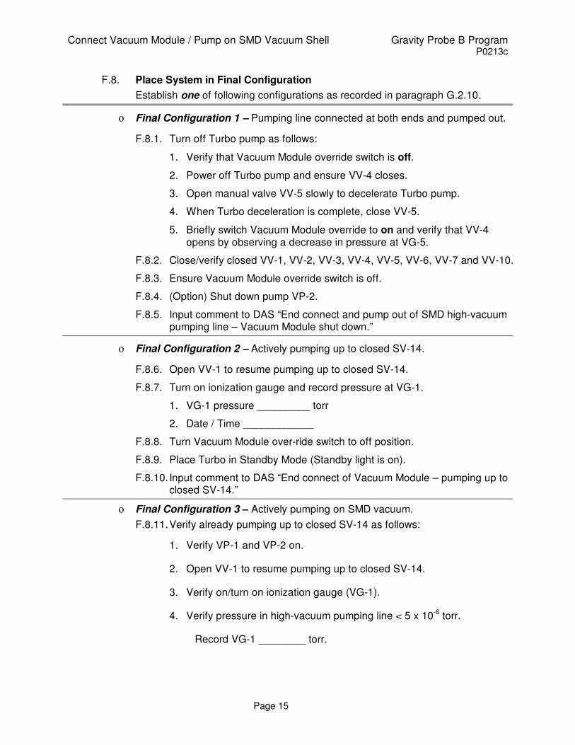
F.8. Place System in Final Configuration
Establish one of following configurations as recorded in paragraph G.2.10.
ο Final Configuration 1 – Pumping line connected at both ends and pumped out.
F.8.1. Turn off Turbo pump as follows:
1. Verify that Vacuum Module override switch is off.
2. Power off Turbo pump and ensure VV-4 closes.
3. Open manual valve VV-5 slowly to decelerate Turbo pump.
4. When Turbo deceleration is complete, close VV-5.
5. Briefly switch Vacuum Module override to on and verify that VV-4 opens by observing a decrease in pressure at VG-5.
F.8.2. Close/verify closed VV-1, VV-2, VV-3, VV-4, VV-5, VV-6, VV-7 and VV-10.
F.8.3. Ensure Vacuum Module override switch is off.
F.8.4. (Option) Shut down pump VP-2.
F.8.5. Input comment to DAS “End connect and pump out of SMD high-vacuum pumping line – Vacuum Module shut down.”
ο Final Configuration 2 – Actively pumping up to closed SV-14.
F.8.6. Open VV-1 to resume pumping up to closed SV-14.
F.8.7. Turn on ionization gauge and record pressure at VG-1.
1. VG-1 pressure _________ torr
2. Date / Time ____________
F.8.8. Turn Vacuum Module over-ride switch to off position.
F.8.9. Place Turbo in Standby Mode (Standby light is on).
F.8.10. Input comment to DAS “End connect of Vacuum Module – pumping up to closed SV-14.”
ο Final Configuration 3 – Actively pumping on SMD vacuum.
F.8.11. Verify already pumping up to closed SV-14 as follows:
1. Verify VP-1 and VP-2 on.
2. Open VV-1 to resume pumping up to closed SV-14.
3. Verify on/turn on ionization gauge (VG-1).
4. Verify pressure in high-vacuum pumping line < 5 x 10⁻⁶
torr.
Record VG-1 ________ torr.

Connect Vacuum Module / Pump on SMD Vacuum Shell Gravity Probe B Program P0213c
Page 16
F.8.12. Input comment to DAS “Begin pumping on SMD with Vacuum Module”.
Note: Refer to DAS instructions for keyboard/mouse operation.
F.8.13. Record pressure in SMD vacuum space:
1. Turn on Vac-ion pump and record time of day _______
2. Use DAS [Monitor Data] for CN 99.
3. When value is steady, record pressure (IP) _______ torr.
4. Exit [Monitor Data] and collect data with [Set Data Interval] to 5 min.
F.8.14. Record pressure in high vacuum pumping line (VG-1) ________ torr
F.8.15. Remove the operator’s closed position handle lock.
CAUTION
Do not proceed until VG-1 pressure is < 5.0 x 10⁻⁶ torr
CAUTION
In the following operation do not turn the handle as it is pulled out. A turning motion could
result in a disengagement of the plug. The plug would then be floating free in the body of
the operator and prove very difficult to retrieve.
F.8.16. Open SV-14 by gently pulling out the valve plug with the operator handle.
F.8.17. Record the following just as the valve is opened:
1. Time of day:________
2. Vac-ion pump (IP)________ torr
3. VG-1 pressure:________ torr
F.8.18. Install the operator-withdrawn handle restrainer.
F.8.19. Wait fifteen minutes and record the following:
1. Time of day:________
2. Vac-ion pump (IP)________ torr
3. VG-1 pressure:________ torr
F.8.20. Ensure that the vacuum module’s over-ride switch is in the off position.
F.8.21. Turn off Vac-ion pump and record time of day: __________.
F.8.22. Input comment to DAS “End connect of Vacuum Module – pumping on SMD Vacuum.”

Connect Vacuum Module / Pump on SMD Vacuum Shell Gravity Probe B Program P0213c
Page 17
F.9. Optional: Leak Check Dewar Seals
F.9.1. Ensure VV-7 closed
F.9.2. Reconnect leak detector to access port at VV-7
F.9.3. Start leak detector
F.9.4. Ensure VG-1 < 1 *E-4 torr
F.9.5. Ensure Vent Disable switch in on position
F.9.6. Record Initial background :________sccs
F.9.7. Open VV-7 and close VV-4
F.9.8. Record background:___________sccs
F.9.9. Flood each of the seals listed below with helium for one minute and verify that no response is observed on the 10
-7 sccs range. If a response
is seen, a bag leak check of sufficient duration to reach steady state value should be performed to verify that the total leak does not exceed 5 x 10
-6 sccs. Record below:
Location Date/time Background (sccs) Leak after 1 min.
(sccs)
Saturation leak
(optional)
BD5B*
BD7B*
BD7A*
BD5A*
Ion Pump
Main tank bayonet
Guard tank bayonet
+Y ARP post
-Y ARP post
*Note: The “A” units are on the right side of the +X axis (in the +Y direction). The Main Tank burst disks
(BD7A/B) are adjacent to the +X axis.
F.9.10. Open VV-4 and close VV-7
F.9.11. Remove leak detector and cap port at VV-7
F.10. Establish Final Alarm Configuration
F.10.1. Set DAS data cycle interval to 15 minutes.
F.10.2. Ensure DAS alarm enabled and record set points if changed
ο Thermal conditions substantially unchanged, alarm set points for Station 200 and lead bag unchanged

Connect Vacuum Module / Pump on SMD Vacuum Shell Gravity Probe B Program P0213c
Page 18
ο Thermal conditions substantially changed, temperature alarm points reset as follows:
a. Top of Lead Bag set point [CN 28] ________ K ( ≤ 6.0 K)
F.10.3. Ensure liquid level sensor alarms enabled, as appropriate, and record set points if changed.
1. Main Tank Level Set Point __________%
2. Guard Tank Level Set Point __________%
F.10.4. Ensure Guard Tank pressure on DAS alarm list and set to alarm at 0.3 torr differential.
F.10.5. Ensure DAS watchdog timer and alarm enabled.
F.10.6. (Option) Continue data recording in Table 1 until such time as SV-14 is closed.
F.10.7. Verify completion of post operations checklist
Completed by:
Witnessed by:
Date: __________
Time:__________
Quality Manager Date
Payload Test Director Date

Connect Vacuum Module / Pump on SMD Vacuum Shell Gravity Probe B Program P0213c
Page 19
Table 1 SMD Vacuum Shell Re-pump Data
Date
Time
VG-2
VG-1
Vac-ion Pump
GT Temp. CN [24]
Comment
torr torr torr K -

Connect Vacuum Module / Pump on SMD Vacuum Shell Gravity Probe B Program P0213c
Page 20
Figure 1. Schematic of Science Mission Dewar plumbing.
3
FEP
2
5
6B
6A
7
1
Open
Neck Tube
Closed
Valve Positions
Guard Tank
GT Vent Lineto GTVVAand GM.
MT Vent Lineto GM. Well Vent through
Dewar Adapter or WellVent Manifold to GM.
SV-9
Main Tank
Vacuum
Shell
Well
Porous
Plug
STRV a,b(5,5 psig)
Well
LLS
Axial
Lok
LLS
H-8D
H-9D
H-3D
H-4D
SV-13
PFCG
FCV
Fill
Cap
Assy
.
6A RAV-6A1 RAV-1 3 RAV-3
5 RAV-52 RAV-2
7 RAV-7
6B RAV-6B
Remote Actuated Valves (RAV)
FCRV4.0 psi
STG
ThrusterVentManifold
PO PumpingLine toVacModule
SV-14
SV-14operator
Bayonet
B3
LLS
LLS
FLRV-a,b
(10, 4 psig)
FLV
FL-G
FLRV assy. temp
replcmnt for (BD3)
BD2
BD1-A
BD1-B
BD7-A
BD7-B
BD5-A
BD5-B

Connect Vacuum Module / Pump on SMD Vacuum Shell Gravity Probe B Program P0213c
Page 21
VP-1
Turbo pump
VG-5
Convectron
VV- 2VV-1
VV-6
VV- 3
VG-4
Capacitance
VRV-41 psi
VRV-2
1/2 psi
VRV-3
1 psi
VRV-1
1/2 psiVG-1
Ionization
VG-3Convectron
Acces s
Port No. 1
VV-5
VV- 7
VV-4
VP-2
Rotary Vane Pump
Exhaust Filt er
Exhaust
VG-2
VV-10
LN2
TR AP
VV-11
RGA
VV-RGA
Main Pump Inlet
ISO 100
KF-50

Connect Vacuum Module / Pump on SMD Vacuum Shell Gravity Probe B Program P0213c
Page 22
APPENDIX 1 PRE OPERATIONS CHECKLIST
DATE CHECKLIST ITEM COMPLETED REMARKS
1. Verify the test procedure being used is the
latest revision.
2. Verify all critical items in the test are
identified and discussed with the test team.
3. Verify all required materials and tools are
available in the test area.
4. Verify all hazardous materials involved in
the test are identified to the test team.
5. Verify all hazardous steps to be performed
are identified to the test team.
6. Verify each team member is certified for the
task being performed and knows their
responsibilities.
7. Confirm that each test team member
clearly understands that he/she has the
authority to stop the test if an item in the
procedure is not clear.
8. Confirm that each test team member
clearly understands that he/she must stop the
test if there is any anomaly or suspected
anomaly.
9. Notify management of all discrepancy
reports or d-log items identified during
procedure performance. In the event an
incident or major discrepancy occurs during
procedure performance management will be
notified immediately.
10. Perform a pretest Engineering and Safety
high-bay walk down. Ensure all
discrepancies are corrected prior to start of
operations.
11. Confirm that each test team member
understands that there will be a post-test team
meeting.
Team Lead Signature:
______________________

Connect Vacuum Module / Pump on SMD Vacuum Shell Gravity Probe B Program P0213c
Page 23
APPENDIX 2 POST OPERATIONS CHECKLIST
DATE CHECKLIST ITEM COMPLETED REMARKS
1. Verify all steps in the procedure were
successfully completed.
2. Verify all anomalies discovered
during testing are properly documented.
3. Ensure management has been
notified of all major or minor
discrepancies.
4. Ensure that all steps that were not
required to be performed are properly
identified.
5. If applicable sign-off test completion.
1. Verify all RAV valve operations
have been entered in log book
7. Verify the as-run copy of procedure
has been filed in the appropriate binder
Team Lead Signature:
______________________
Related Documents