Congratulations, you have just acquired a Zodiac Chlor Perfect which will allow you to disinfect your pool water without constraints. Chlor perfect measures the water’s ORP (OxydoReduction Potential = water’s disinfection capacity) using a ORP sensor placed on the filtering circuit which permanently analyses the pool water. Depending on ORP reading, Chlor Perfect will inject the quantity of product needed (liquid chlorine) to maintain the balance of the pool water using its dosing pump. Contents Description of your Chlor Perfect page 17 1.1 Parts identification...................................................................................................................................................................................................................................... 17 1.2 The control panel......................................................................................................................................................................................................................................... 18 Installation page 19 2.1 Recommendations...................................................................................................................................................................................................................................... 19 2.2 Technical data ............................................................................................................................................................................................................................................... 19 2.3 Reference installation diagram................................................................................................................................................................................................... 19 2.4 Box fixture and electric connection..................................................................................................................................................................................... 20 2.5 Installing the sensor and the injection point .............................................................................................................................................................. 20 Commissioning and operation page 21 3.1 Calibration procedure.............................................................................................................................................................................................................................. 21 3.2 Chlor Perfect injection rule............................................................................................................................................................................................................22 3.3 Boost Mode .....................................................................................................................................................................................................................................................22 Settings: “Parameter” menu page 23 4.1 Language.............................................................................................................................................................................................................................................................23 4.2 “Parameter” menu default settings......................................................................................................................................................................................23 4.3 Set point ............................................................................................................................................................................................................................................................23 4.4. “OFA” overdose safety ......................................................................................................................................................................................................................24 4.5 Calibration activation...........................................................................................................................................................................................................................24 4.6 Filtering operation detection .......................................................................................................................................................................................................25 4.7 Boost Mode......................................................................................................................................................................................................................................................25 4.8 Reinitialising the appliance............................................................................................................................................................................................................25 Maintenance of your Chlor Perfect page 26 5.1. Changing the peristaltic tube.......................................................................................................................................................................................................26 5.2. Wintering the Chlor Perfect .........................................................................................................................................................................................................26 Water quality page 27 Alarms page 27 Troubleshooting page 28 Warranty page 28 On-line registration page 29 1 2 3 4 5 6 7 8 9 10 The symbol indicates important information that it is imperative to take into consideration in order to avoid all risks of harm to persons or damage to the appliance. The symbol indicates useful information. Description of your Chlor Perfect 1.1 Parts identification List of the items present in the packaging and needed to install your Chlor Perfect: 1 Chlor Perfect Regulator 2 Suction cane with 2 m PVC tube and 3 m cable 3 Wall mounting bracket 4 Wall mounting kit (2 plugs & 2 screws) 5 ORP sensor model Z35R1P-17 with 5 m shielded cable 6 Sensor holder model PSS3 (1/2”) 7 FPM lipped injection valve (3/8”) 8 1/2’’ – 3/8’’ adapter for injection valve 9 - 10 Fixing collars to fit the injection valve and sensor holder (DN 50 mm) 11 Buffer solution 465 mV 12 Polyethylene injection pipe (5 m) 1 1 2 3 4 5 6 7 8 9 10 11 12 16 17 EN

Welcome message from author
This document is posted to help you gain knowledge. Please leave a comment to let me know what you think about it! Share it to your friends and learn new things together.
Transcript

Congratulations, you have just acquired a Zodiac Chlor Perfect which will allow you to disinfect your pool water without constraints.
Chlor perfect measures the water’s ORP (OxydoReduction Potential = water’s disinfection capacity) using a ORP sensor placed on the fi ltering circuit which permanently analyses the pool water.
Depending on ORP reading, Chlor Perfect will inject the quantity of product needed (liquid chlorine) to maintain the balance of the pool water using its dosing pump.
Contents
Description of your Chlor Perfect page 171.1 Parts identifi cation ...................................................................................................................................................................................................................................... 171.2 The control panel .........................................................................................................................................................................................................................................18
Installation page 192.1 Recommendations ...................................................................................................................................................................................................................................... 192.2 Technical data ............................................................................................................................................................................................................................................... 192.3 Reference installation diagram ................................................................................................................................................................................................... 192.4 Box fi xture and electric connection ..................................................................................................................................................................................... 202.5 Installing the sensor and the injection point .............................................................................................................................................................. 20
Commissioning and operation page 213.1 Calibration procedure ..............................................................................................................................................................................................................................213.2 Chlor Perfect injection rule ............................................................................................................................................................................................................223.3 Boost Mode .....................................................................................................................................................................................................................................................22
Settings: “Parameter” menu page 234.1 Language.............................................................................................................................................................................................................................................................234.2 “Parameter” menu default settings ......................................................................................................................................................................................234.3 Set point ............................................................................................................................................................................................................................................................234.4. “OFA” overdose safety ......................................................................................................................................................................................................................244.5 Calibration activation ...........................................................................................................................................................................................................................244.6 Filtering operation detection .......................................................................................................................................................................................................254.7 Boost Mode ......................................................................................................................................................................................................................................................254.8 Reinitialising the appliance ............................................................................................................................................................................................................25
Maintenance of your Chlor Perfect page 265.1. Changing the peristaltic tube .......................................................................................................................................................................................................265.2. Wintering the Chlor Perfect .........................................................................................................................................................................................................26
Water quality page 27
Alarms page 27
Troubleshooting page 28
Warranty page 28
On-line registration page 29
1
2
3
4
5
6
7
8
9
10
16
The symbol indicates important information that it is imperative to take into consideration in order to avoid all risks of harm to persons or damage to the appliance.
The symbol indicates useful information.
Description of your Chlor Perfect
1.1 Parts identifi cation
List of the items present in the packaging and needed to install your Chlor Perfect:
1 Chlor Perfect Regulator
2 Suction cane with 2 m PVC tube and 3 m cable
3 Wall mounting bracket
4 Wall mounting kit (2 plugs & 2 screws)
5 ORP sensor model Z35R1P-17 with 5 m shielded cable
6 Sensor holder model PSS3 (1/2”)
7 FPM lipped injection valve (3/8”)
8 1/2’’ – 3/8’’ adapter for injection valve
9 - 10 Fixing collars to fi t the injection valve and sensor holder (DN 50 mm)
11 Buffer solution 465 mV
12 Polyethylene injection pipe (5 m)
1
1
2
3
4 5
6
7
8
9 10
11 12
17
16 17
EN

1.2 The control panel
1
2
3
4
5 6 7
8
9
10
11
12
13
1 LCD screen one 16 character line, black display with orange back lighting.Left side: coupling zone (alarms) / Right side: ORP value display
2 Peristaltic pump
3 Connection for the polyethylene injection pipe.
4 Connection between the PVC suction tube and the suction cane.
5 Cable gland: the direct coupling cable to the fi ltering system (220-240 V AC only when the fi ltering is operational).
6 Cable gland: cable connecting the control box to the level sensor in the suction cane.
7 Cable gland: cable for mains power supply 220-240 V AC.
8 ORP sensor BNC connector: the sensor cable is connected to the regulator box using this connector.
9 Main switch: used to power on the regulator.
10 Navigation key “q”: navigation through the “Parameter” menu settings.
11 “SET/Esc” key: key used to exit the “Parameter” menu. Also used to view the value for the pH set point when pressed continuously.
12 Navigation key “p”: navigation through the “Parameter” menu settings.
13 “CAL/Enter” key: key to activate the sensor calibration mode (The key must be held down for 5 seconds). Also used to validate the selections from the “Parameter” menu.
L’appui simultané sur les boutons “ p “ et “ q “ pendant 5 secondes active le mode “ Boost “ (super-chloration, voir paragraphe 3.3).
18
Installation
2.1 Recommendations
WARNING: CHLOR PERFECT MUST BE INSTALLED BY AN EXPERIENCED POOL PROFESSIONAL.
> BEFORE CARRYING OUT ANY INTERVENTIONS INSIDE THE CHLOR PERFECT REGULATOR BOX, DISCONNECT IT FROM THE POWER SUPPLIES.
> Before starting to install the Chlor Perfect regulator, check that all the components needed to install are present and read this instruction manual carefully.
> If the instructions contained in the manual are not respected, harm to persons and/or damage to the appliance may occur.
> During the installation phase of the Chlor Perfect, check the following:
• that the voltage of the power supply corresponds to the voltage indicated on the side of the
appliance • the electrical installation complies with standard NF C15-100 (or equivalent for other European
countries) • that the injection point pressure is lower than 1.5 bar • that the pump’s protection cover is correctly fi tted • that the suction tube is immersed in the disinfectant product container with the suction cane and
is connected to the peristaltic pump (left side). • that the injection tube is connected on one side to the peristaltic pump (right side) and on the
other side to the pool return pipe via the injection valve.
> Use liquid chlorine specifi c for use in a private pool. Zodiac Pool Care Europe cannot be held liable for the use of an inappropriate product.
> The ORP sensor is fragile, it must be handled with care.
2.2 Technical data
Size (L x w x h) 240 x 200 x 90 mmWeight (appliance, sensor, cane and pipes) 1.7 kgPower supply 50 Hz 220-240 V AC / 50 HzConsumption 18 WPump fl ow 5 L/hMaximum counter pressure 1.5 barORP control range 10 - 1000 mVAppliance accuracy +/- 10 mVSensor calibration Single point semi automatic
2.3 Reference installation diagramChlor Perfect is installed on the fi ltering circuit:
THE LINEAR DISTANCE BETWEEN THE SENSOR AND THE INJECTION POINT MUST NOT BE LESS THAN 60 CM.The injection point must be the last element on the return before the pool.The electric power supply cables and ORP cables must pass through a different location than the big pump supply and other electric cables in order to avoid disruptive currents.The maximum pressure in the pipes must not be greater than 1.5 Bar.In order to extend the life of the peristaltic tube, the pressure should not exceed 1 bar.On installations having a heating system or any other equipment, the equipment should be located after the ORP sensor and before the liquid chlorine injection point.
2
60 cm
19
18 19
EN

OPTION (NOT PROVIDED IN THE PACKAGING): POD KIT
The “POD kit” is an accessory that is used to group together the measurement sensors in the same place when using a Chlor Perfect combined with a Zodiac pH Perfect (or other regulation using a 12 mm Ø sensor).
The “POD kit” includes a multi-diameter fi xing collar (DN50 mm or DN63 mm) and a measurement chamber designed to obtain more reliable readings (+ assembly accessories).
The “POD kit” is available from your reseller.
2.4 Box fi xture and electric connection
Install the Chlor Perfect regulator using the supplied fi xing kit on a rigid support (a vertical wall) in an easy to access location.
The electric connection of the Chlor Perfect must be carried out by an experienced pool professionalt.
“standard” Chlor Perfect electric connection:
2.5 Installing the sensor and the injection point
The sensor must be placed vertically, or even at a max of 45°, but always above the rigid pipe.It must NEVER be placed horizontally or below the rigid pipe.
Correct positions ✔ Incorrect positions ✗
Drill a hole of a diameter between 16 and 22 mm included on the pipe at the locations selected for the ORP sensor and the injection point (see diagram in paragraph 2.3). Next fi t the fi xing collars aligning them opposite the previously drilled holes.
Use Tefl on® tape to make sure the threads on the sensor holder, the injection valve and its adapter are watertight.
CT
220-240 V AC 50 Hz
L30 mA
N220-240 V AC
50 Hz
220-240 V AC 50 Hz
20
Commissioning and operation
Remark: Refer to paragraph 4.1 to change the display language.
3.1 Calibration procedure
Calibration of the sensor must be carried out when installing the Chlor Perfect and ideally every 2 months to make sure your appliance continues to operate in the best conditions.
- Calibration must be carried out every time you commission your pool at the start of the season.- The calibration procedure is carried out when the fi ltering system is not running thanks to its double
supply (the appliance remains powered on). Stop the fi ltering system and close the valves so that the ORP sensor holder is isolated from water fl ow before starting.
Procedure:
(2) (3)(1)
1. Loosen the sensor holder and delicately remove the sensor from the duct
2. Rinse the sensor in clean water and shake off the droplets of water (do not use a cloth).
3. Plunge the sensor into the bottle of “mV465” buffer solution.
(4a) (4c)(4b) (5)
4. Keep the “CAL/Enter” key pressed down for 5 seconds until “Calibration” is displayed on the LCD screen (fi gure 4a). Press the “CAL/Enter” key again as shown on the screen to start calibration on 465 mV (fi gure 4b).An automatic progress bar appears during 30 seconds (fi gure 4c).
5. After 30 seconds the appliance displays the accuracy of the sensor readings as a percentage.Example: 100% for a new sensor. If < 25%, see chapter 8.To fi nish the calibration, press the “CAL:Enter” key. The appliance will return to measurement mode.
> Once calibration has been carried out, the Chlor Perfect is ready to regulate your pool disinfection. If the need for chlorine is very high (< 550 mV) it may be necessary to pause the overdose safety (OFA) for 24 or 48 hours (see paragraph 4.4).
> The Chlor Perfect peristaltic pump is self priming.However, it is possible to run it manually by keeping the “p” key pressed down.
3
21
20 21
EN

3.2 Chlor Perfect injection rule
Exclusive Zodiac proportional cyclic dosing
Chlor Perfect is designed to automatically maintain a level of chlorine making it possible to maintain a good disinfection of the pool. It permanently measures the water’s disinfection potential (also known as “ORP potential”) and injects liquid chlorine depending on the needs. The ORP potential is measures in millivolts (mV).
In order to reach the set point in the best conditions, your Chlor Perfect automatically detects the difference between the ORP values measured in the pool and the set point value (default value = 740 mV, see paragraph 4.3 to modify it).Chlor Perfect’s proportional injection is cyclic and the cycle duration is 10 minutes. What changes the doses are the automatic balancing of injection times and pauses.The proportionality automatically adjusts, the balancing between the different doses is made using 70 mV steps.
Example of 4 cycles with a set point at 740 mV: ORP ≥ 670 mV : 20% injection (2’) & 80% pause (8’) ORP ≥ 600 mV : 50% injection (5’) & 50 % pause (5’) ORP ≥ 530 mV : 75% injection (7’30’’) & 25% pause (2’30’’) ORP < 530 mV : 100% injection (10’, continuous)
mV ppm free chlorine+
750740 Set point = 740 mV 1,80730
20%
720710700 1,00690680670 0,90660
50%
650640630620610600 0,40590
75%
580570560550540530 0,20520
100%510500490480470460450440
-10 min 10 min 10 min 10 min Dosage cycle
ti mes
3.3 Boost Mode
Chlor Perfect is equipped with an exclusive function that makes it possible to manually and rapidly increase the level of free chlorine in the pool (stormy weather, high number of bathers...). The duration of the Boost mode is set to 10 minutes by default (see paragraph 4.7 to change the duration).
When the Chlor Perfect is switched on, press the “p” and “q” keys simultaneously for 5 seconds to activate the Boost mode. “Boost” followed by the number of minutes remaining will be displayed on the left of the LCD screen.
22
Settings: “Parameter” menu
4.1 Language
The default language on the Chlor Perfect is French.You have a choice of 6 languages for the LCD display: French, English, German, Spanish, Italian and Dutch.To change the language, after having entered the “Parameter” menu (see paragraph 4.2), activate the selection list by pressing the “CAL/Enter” key (a small arrow appears on the right of the screen and the language blinks) then select the language using the “p” and “q” navigation keys.Validate the choice by pressing the “CAL/Enter” key.
4.2 “Parameter” menu default settings
Chlor Perfect is pre-set in the factory with the following parameter values (adapted to most situations):a. Language: Frenchb. ORP set point: 740 mVc. “OFA” overdosage safety: 4 hoursd. Calibration: activated (465 mV)e. Filter operation detection: activatedf. Boost mode duration: 10 minutes
To access the “Parameter” menu the appliance must be switched on. Press the “CAL/Enter” and “SET/Esc” keys simultaneously for 5 seconds until the LCD screen displays “Parameter”.
This “Parameter” menu gives access to the following settings:o Languageo Set pointo Triggering time for the “OFA” overdose safetyo Calibration activationo Filtering operation detectiono Boost mode duration
To exit the “Parameter” menu, press the “SET/Esc” key and select ”Save” or ”No Save” using the ”p” and ”q” navigation keys to save or cancel the new settings.Validate the choice by pressing the “CAL/Enter” key.
4.3 Set point
The default set point for Chlor Perfect is 740 mV.This value corresponds to optimal chlorination for most private pools.To change it, once you have entered the “Parameter” menu, activate the selection list by pressing the “CAL/Enter” key (the ORP value blinks), then select the desired value using the “p” and “q” navigation keys.The adjustment is by segments (hysteresis) of 10 mV.Validate the choice by pressing the “CAL/Enter” key.
It s also possible to directly access the set point setting by pressing the “SET/Esc” key for a long time (keep it pressed down while changing the value using the “p” and “q” keys).
4
23
22 23
EN
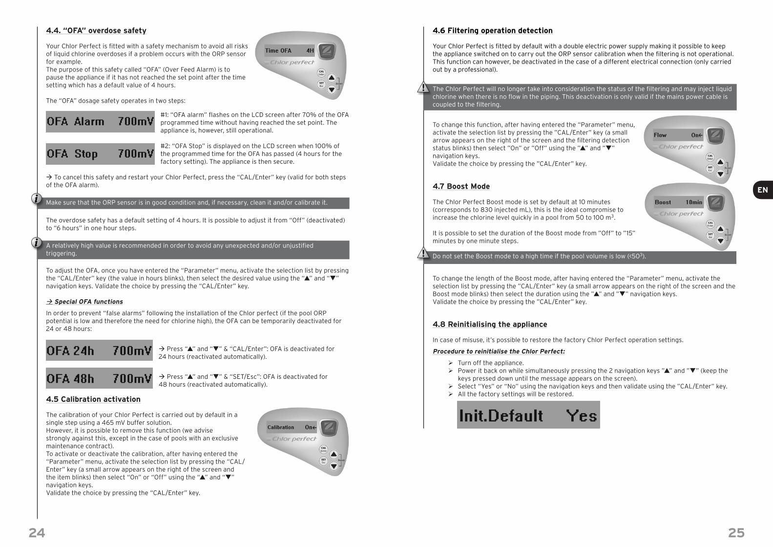
4.4. “OFA” overdose safety
Your Chlor Perfect is fi tted with a safety mechanism to avoid all risks of liquid chlorine overdoses if a problem occurs with the ORP sensor for example.The purpose of this safety called “OFA” (Over Feed Alarm) is to pause the appliance if it has not reached the set point after the time setting which has a default value of 4 hours.
The “OFA” dosage safety operates in two steps:
#1: “OFA alarm” fl ashes on the LCD screen after 70% of the OFA programmed time without having reached the set point. The appliance is, however, still operational.
#2: “OFA Stop” is displayed on the LCD screen when 100% of the programmed time for the OFA has passed (4 hours for the factory setting). The appliance is then secure.
To cancel this safety and restart your Chlor Perfect, press the “CAL/Enter” key (valid for both steps of the OFA alarm).
Make sure that the ORP sensor is in good condition and, if necessary, clean it and/or calibrate it.
The overdose safety has a default setting of 4 hours. It is possible to adjust it from “Off” (deactivated) to “6 hours” in one hour steps.
A relatively high value is recommended in order to avoid any unexpected and/or unjustifi ed triggering.
To adjust the OFA, once you have entered the “Parameter” menu, activate the selection list by pressing the “CAL/Enter” key (the value in hours blinks), then select the desired value using the “p” and “q” navigation keys. Validate the choice by pressing the “CAL/Enter” key.
Special OFA functions
In order to prevent “false alarms” following the installation of the Chlor perfect (if the pool ORP potential is low and therefore the need for chlorine high), the OFA can be temporarily deactivated for 24 or 48 hours:
Press “p” and “q” & “CAL/Enter”: OFA is deactivated for 24 hours (reactivated automatically).
Press “p” and “q” & “SET/Esc”: OFA is deactivated for 48 hours (reactivated automatically).
4.5 Calibration activation
The calibration of your Chlor Perfect is carried out by default in a single step using a 465 mV buffer solution.However, it is possible to remove this function (we advise strongly against this, except in the case of pools with an exclusive maintenance contract).To activate or deactivate the calibration, after having entered the “Parameter” menu, activate the selection list by pressing the “CAL/Enter” key (a small arrow appears on the right of the screen and the item blinks) then select “On” or “Off” using the “p” and “q” navigation keys.Validate the choice by pressing the “CAL/Enter” key.
24
4.6 Filtering operation detection
Your Chlor Perfect is fi tted by default with a double electric power supply making it possible to keep the appliance switched on to carry out the ORP sensor calibration when the fi ltering is not operational.This function can however, be deactivated in the case of a different electrical connection (only carried out by a professional).
The Chlor Perfect will no longer take into consideration the status of the fi ltering and may inject liquid chlorine when there is no fl ow in the piping. This deactivation is only valid if the mains power cable is coupled to the fi ltering.
To change this function, after having entered the “Parameter” menu, activate the selection list by pressing the ”CAL/Enter” key (a small arrow appears on the right of the screen and the fi ltering detection status blinks) then select ”On” or ”Off” using the ”p” and ”q” navigation keys.Validate the choice by pressing the ”CAL/Enter” key.
4.7 Boost Mode
The Chlor Perfect Boost mode is set by default at 10 minutes (corresponds to 830 injected mL), this is the ideal compromise to increase the chlorine level quickly in a pool from 50 to 100 m3.
It is possible to set the duration of the Boost mode from ”Off” to ”15” minutes by one minute steps.
Do not set the Boost mode to a high time if the pool volume is low (<503).
To change the length of the Boost mode, after having entered the “Parameter” menu, activate the selection list by pressing the ”CAL/Enter” key (a small arrow appears on the right of the screen and the Boost mode blinks) then select the duration using the ”p” and ”q” navigation keys.Validate the choice by pressing the ”CAL/Enter” key.
4.8 Reinitialising the appliance
In case of misuse, it’s possible to restore the factory Chlor Perfect operation settings.
Procedure to reinitialise the Chlor Perfect:
Turn off the appliance. Power it back on while simultaneously pressing the 2 navigation keys ”p” and ”q” (keep the
keys pressed down until the message appears on the screen). Select “Yes” or “No” using the navigation keys and then validate using the ”CAL/Enter” key. All the factory settings will be restored.
25
24 25
EN
Maintenance of your Chlor Perfect
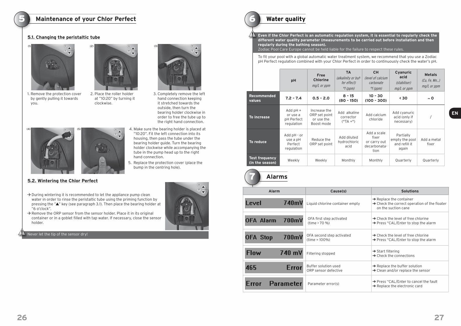
5.1. Changing the peristaltic tube
1. Remove the protection cover
by gently pulling it towards you.
2. Place the roller holder at ”10:20” by turning it clockwise.
3. Completely remove the left hand connection keeping it stretched towards the outside, then turn the bearing holder clockwise in order to free the tube up to the right hand connection.
4. Make sure the bearing holder is placed at ”10:20”. Fit the left connection into its housing, then pass the tube under the bearing holder guide. Turn the bearing holder clockwise while accompanying the tube in the pump head up to the right hand connection.
5. Replace the protection cover (place the bump in the centring hole).
5.2. Wintering the Chlor Perfect
During wintering it is recommended to let the appliance pump clean water in order to rinse the peristaltic tube using the priming function by pressing the ”p” key (see paragraph 3.1). Then place the bearing holder at ”6 o’clock”. Remove the ORP sensor from the sensor holder. Place it in its original container or in a goblet fi lled with tap water. If necessary, close the sensor holder.
Never let the tip of the sensor dry!
5
(1) (2) (3)
(5)(4)
26
Water quality
Even if the Chlor Perfect is an automatic regulation system, it is essential to regularly check the different water quality parameter (measurements to be carried out before installation and then regularly during the bathing season).Zodiac Pool Care Europe cannot be held liable for the failure to respect these rules.
To fi t your pool with a global automatic water treatment system, we recommend that you use a Zodiac pH Perfect regulation combined with your Chlor Perfect in order to continuously check the water’s pH.
pHFree
Chlorine
mg/L or ppm
TA
(alkalinity or buf-fer effect)
°f (ppm)
CH
(level of calcium carbonate
°f (ppm)
Cyanuricacid
(stabiliser)
mg/L or ppm
Metals
(Cu, Fe, Mn…)
mg/L or ppm
Recommended values
7.2 – 7.4 0.5 – 2.08 – 15
(80 – 150)10 – 30
(100 – 300)< 30 ≈ 0
To increase
Add pH + or use a
pH Perfect regulation
Increase the ORP set point
or use the Boost mode
Add alkaline corrector ("TA +")
Add calcium chloride
Add cyanuric acid (only if necessary)
/
To reduce
Add pH - or use a pH Perfect
regulation
Reduce the ORP set point
Add diluted hydrochloric
acid
Add a scale fi xer
or carry out decarbonata-
tion
Partially empty the pool
and refi ll itagain
Add a metal fi xer
Test frequency (in the season)
Weekly Weekly Monthly Monthly Quarterly Quarterly
Alarms
Alarm Cause(s) Solutions
Liquid chlorine container empty➔ Replace the container➔ Check the correct operation of the fl oater
on the suction cane
OFA fi rst step activated (time > 70 %)
➔ Check the level of free chlorine➔ Press “CAL/Enter to stop the alarm
OFA second step activated(time = 100%)
➔ Check the level of free chlorine➔ Press “CAL/Enter to stop the alarm
Filtering stopped➔ Start fi ltering➔ Check the connections
Buffer solution usedORP sensor defective
➔ Replace the buffer solution➔ Clean and/or replace the sensor
Parameter error(s)➔ Press “CAL/Enter to cancel the fault➔ Replace the electronic card
6
7
27
26 27
EN

Troubleshooting
Problems Causes Solutions
The Chlor Perfect displays a value close to 0 mV
Problem on the sensor cable and/or the BNC connector
➔ Check that the connection between the ORP sensor and the Chlor Perfect is not short circuited (between the central core of the cable and the outer shielding)
➔ Check that there is no humidity and/or condensation at the BNC connector level
The appliance displays a constantly fl uctuating value
Sensor cable damaged ➔ Check the cable and/or the BNC connector
Sensor cable too close to an electric cable causing disturbances
➔ Place the sensor cable elsewhere (removed from any electromagnetic disturbances).
Calibration impossible (error message)
or
Reliability of the ORP sensor < 25%
Buffer solution defective➔ Check that the solution used is 465 mV
➔ Use a new 465 mV buffer solution and start the calibration again
The sensor is dirty or defective
➔ Check the end of the sensor
➔ Check the porosity of the sensor
➔ As a fi nal resort, clean the sensor by leaving its extremity in a 10% solution of hydrochloric acid
The ORP sensor is worn ➔ Replace the ORP sensor
The ORP sensor is slow to respond
The ORP sensor is electrostatically charged
➔ During calibration the ORP sensor MUST NOT be wiped with a cloth or paper; shake it gently after rinsing.
The level of free chlorine is too low (murky water)
The water balance is incorrect (high pH...)
➔ Check and correct the water balance parameters (see chapter 6)
➔ Use the Boost mode is necessary
ORP set point is too low ➔ Make sure the ORP set point is greater than 700 mV
Daily fi ltering time too low➔ The daily fi ltering time must be of at least 12 hours/
day during the season
The free chlorine level is too high
The water balance is incorrect (low pH...)
➔ Check and correct the water balance parameters (see chapter 6)
ORP set point is too high➔ Make sure the ORP set point is close to 740 mV
➔ If necessary switch off the Chlor perfect
Warranty
PrincipleExcept for terms to the contrary, we contractually guarantee the correct operation of our new products. We guarantee that our products correspond to their technical specifi cities and are free from material or manu-facturing defects.In all events, this warranty is limited, at our discretion, either to the repair or to the exchange by a new or reconditioned product, or the refund of Products we acknowledge to be defective. The transport costs for the Product that is repaired or replaced and delivered to our customer is at our expense, excluding labour costs, travel and/or accommodation paid for by us during the repairs outside of Metropolitan France and to the ex-clusion of the payment of any compensation. Any product returns must be decided and accepted by us beforehand. No return at the sole initiative of the Customer will be accepted.More especially, the warranty on spare parts can only be activated after analysis and expertise by our com-pany of the returned parts and the decision to replace these parts.In all events, the legal warranty of the seller continues to apply.For the warranty to be active, our Customer and End user undertake to respect the water balance parameters according to the following criteria: - pH: 6.8 < pH < 7.6- free chlorine: < 3.0 mg/L- stabiliser (if used) : < 75 mg/L- total dissolved metals (iron, manganese, copper, zinc…) : < 0.1 mg/LRemark: The use of water from a borehole or well is prohibited.
8
9
28
General limitationsThis guarantee does not apply to visible defects, i.e. visual defects visible but not declared by the Customer at product delivery.Are also excluded the defects or deteriorations caused by the inappropriate nature of the product to the end user’s needs, by normal wear, through negligence, through an incorrect use or an incorrect installation or a use that is not compliant with the recommendations in this manual, by insuffi cient maintenance and/or accidental mishandling, by bad storage and/or by studies, instructions and/or specifi cations issued by our Customer.All modifi cations made to the Products by the Customer, by the User or by a third party automatically end the entire guarantee. The same applies to the case where original parts have been replaced by parts not sold by us.Our Customer shall make sure of the compatibility of our products with the other pool equipment by question-ing the different manufacturers; as well as the installation and commissioning rules to be complied with for the correct operation of the entire system.In the case that the product is returned to our workshop, the transportation costs will be at the expense of the fi nal user, excepting those mentioned in paragraph 1.The immobilisation and loss of use of an appliance caused by the necessity to repair cannot give rise to com-pensation. This guarantee will also be excluded in the event of failure to pay or overdue payment of the Product by the Customer.
LengthThe date on which the contractual warranty begins is the date on the sales invoice of the new Product from our Customer to the end User. The invoice is required and is the condition of any work under guarantee. Failure to do this will result in the Customer supporting all the damaging consequences for our company alone for all claims from Users using the contractual guarantee after its expiry date.The reparations and/or replacements made under this guarantee will not have the effect of extending its duration.
Special terms for Automatic Regulation Line productsWe guarantee that all products correspond to their technical specifi cations and are free from material or manufacturing defects, and that they correspond to technical evolution and state of the art when placed on the market. Later modifi cations made to our products (improvements or modifi cations following the product’s technologi-cal progress) cannot be the cause of an intervention by our company.Are excluded from the guarantee:• The normal wear of parts such as the sensor, the peristaltic tube, the buffer solution(s) or the check valve.• Electrical damage caused by lightning or an incorrect electric connection.• Damage due to shocks, incorrect use or faulty maintenance.The warranty is for 2 years starting on the invoice date for the invoice for the sale of the new product by our Customer to the end user for the entire product line.
All requests under guarantee must be sent to your Retailer. We recommend that you keep your purchase invoice carefully if you require assistance for your product.
On-line registration
Register your product on our website: www.zodiac-poolcare.com You will be the fi rst to be informed of new Zodiac products and special offers. You can help us to constantly improve our product quality.
Recycling
Your appliance is at the end of its life span. You wish to dispose of it or to replace it. Do not place it in the trash nor in your area’s selective sorting containers.This symbol on a new appliance means that the equipment must not be thrown away; it will be selectively collected for the purpose of reuse, recycling or creating value. If it contains substances that are potentially harmful to the environment, they will be eliminated or neutralised.Ask your reseller about how to recycle your appliance and the bodies that can do so.
10
29
28 29
EN
Related Documents