The 24×24×64-mm Sensor Head redefines the meaning of ultra-compact The 24×24×64-mm Sensor Head redefines the meaning of ultra-compact Ultra-compact and Ultra-lightweight Stable Measurements for Any Material Robust Sensor Head Structure » » » Confocal Fiber Displacement Sensor ZW Series Standard Feature New Right-angle type

Welcome message from author
This document is posted to help you gain knowledge. Please leave a comment to let me know what you think about it! Share it to your friends and learn new things together.
Transcript

The 24×24×64-mm Sensor Head redefines the meaning of ultra-compactThe 24×24×64-mm Sensor Head redefines the meaning of ultra-compact
Ultra-compact and Ultra-lightweightStable Measurements for Any Material
Robust Sensor Head Structure
» »
»
Confocal Fiber Displacement Sensor ZW Series
Standard Feature
NewRight-angle type

Goes beyond traditional displacement sensor concepts with a new confocal principle.
2
Displacement Sensors are indispensable
in non-contact measurement of heights,
thicknesses, and other dimensions in
machine operation control. However,
building them into the system has always
presented problems. The Confocal Fiber
Displacement ZW Series Sensor solves
these problems in ways that were not
possible with traditional triangulation.
The ZW-series Sensors provide the
compact size, light weight, immunity to
electrical/magnetic noise, and other
features to make them ideal for solving
installation space problems.
And OMRON’s new confocal principle
provides the measurement resolution
that is needed for operation control.
The ZW Series solves the problems that
came with laser triangulation, such as
deviations between different materials
and inclination tolerance.
Two Types of Sensor Heads
Measuring center distance
-EtherCAT® is a registered trademark and patented technology, licensed by Beckhoff Automation GmbH, Germany. -EtherNet/IP™ are the trademarks of ODVA.-ATI™, Radeon™ are trademarks of Advanced Micro Devices, Inc. in USA.-Sysmac is a trademark or registered trademark of OMRON Corporation in Japan and other countries for OMRON factory automation products.-Microsoft, Visual Basic, and Windows are either registered trademark of Microsoft Corporation in the United States and other countries.-Other company names and product names in this document are the trademarks or registered trademarks of their respective companies.
40
30
20
0
ZW-S40ZWZW-S30ZW
ZW-S20ZW
(mm)
7
ZW-S07ZW
Measurincenter dist
Straight type Right-angle type
ZW-SR07ZW-SR07
ZW-SR20
ZW-SR40
ZW-SSR20
ZW-ZW-ZW-SR 777SR07
ZW
Standard-feature EtherCAT
Standard-feature EtherNet/IP ™
Expanded Communications
P.10

3
The Three Benefits of OMRON’s White Light Confocal Principle
Ultra-compact and Ultra-lightweightThe slim design measures only 24 × 24 mm. It weighs only 105 g. This incredibly compact size could not be achieved with traditional triangulation. Any objects can be measured with the Sensor mounted perpendicular to them to save even more space.
Robust Sensor Head StructureThe sensor head design maintains reliable operation in installations with electronic and magnetic noise. Devices in close proximity will not be affected by noise or heat from the sensor head or fiber cables due to their advanced design.
Stable Measurements for Any MaterialYou can measure objects of any material or color at the same position. A wide angle characteristic of ±8° enables high-resolution measurement of the position even for large objects with mirror-like surfaces without being affected by warping.
P.4
P.8
P.6
No electronic parts.
SubstrateGlass
White ceramic
SUS
Mirror

4
Ultra-compact and Ultra-lightweight
Utilize Narrow Spaces in MachinesThe 24 × 24-mm Sensor Head fits easily into essentially any machine.
Triangulation sensor
Volume ratio1/8 *
Weight ratio1/8 *
Mounting area Reduced to 1/7*
With traditional triangulation, it was necessary to use either diffuse reflec-tion or regular reflection depending on the material. However, the confo-cal principle used for the ZW Series eliminates the need to change the Sensor installation even if the material changes.
Triangulation sensor
Volurat1/8
Weigrat1/8//
Mounting area Reduced to 1/7*
ZW SeriesTraditional Triangulation Model
Substrate SubstrateGlass Glass
Diffuse-reflective Sensor
Regular-reflective Sensor
The Sensor can be installed perpendicular to the object regardless of the material.
Substrate Glass Substrate Glass
Height Control of a Dispenser Nozzle
Thickness Measurement of a Metal Tube
64mm
24mm24mm
*In-house comparisons.
*In-house comparison.
Space restrictions, heat generation, and mutual interference often prevent side-by-side installation of
many traditional triangulation sensors. The compact, non-heat generating ZW-series Sensor Head
eliminates these problem. Furthermore, the right-angle type Sensor Head can be installed in a limited
space over workpieces without a turning mirror.
The traditional sensors generally measure the thickness of a workpiece by calculating the difference
between the heights of the stage and the top surface of the workpiece. The ZW-series Sensor Head
can be installed in the small space under the stage to directly measure the height from the top and
bottom surfaces of the workpiece, which enables more accurate thickness inspection.
Installation in Tight Spaces
Minimum pitch
24 mm
Thickness s MeMeasurementof a Metal Tubbee
of
ad
Thickness Inspection of Small Electronic Parts
Height Conntrtrolol oof f a Dispenseser r NoNozzle

5
An Extension Fiber Cable can be used between the Sensor Head and Controller to extend the distance to up to 32 m. Attach the Sensor Head to a moving part and place the Controller in the control panel or other convenient location to achieve a flexible system design.
Cable Extendable to 32 m
Flexible Fiber Cable for Easy Installation
The Controller connects to the Sensor Head with a 2-mm-diam-eter Flexible Fiber Cable. The Cable has cleared a bending test consisting of 2,000,000* repeti-tions for reliable application on moving parts.
Smooth Movement and Stopping
Using power cylinders to move sensors to measurement positions only when necessary so that the sensors do not interfere with machine motion resulting in delays in measurements while waiting for settling time if the sensors are heavy. A ZW-series Sensor Head, however, weighs only 105 g so that measurements can be made as soon as the cylinder operation stops.
Sensor Head
Connecting adapter
Controller
Cable diameter: 2 mmMinimum bending radius: 20 mm
R
Standard Fiber Cable
0.3 or 2 mExtension Fiber Cable
30 m max.
Ultra-thin
Cable
r
Bonding Height Inspection
le Fiber Cable for Easy Installation
tiime if the sensnsorors s arare e heheavavy.y. AA ZZW-W series SSene sor Head, howeever, weighs only 105 g so thahatt memeasasuru emmenentsts ccanan bbee mam de aass sosoon as the cylindderer oopeperation stops.
Bonding Height Inspe
Moved.
Stopped.
Time
Time
ZW Series
Traditional Triangulation Model
Degree of oscillation
Degree of oscillation
*Cable was tested with OMRON’s bending test consisting of 2,000,000 bends to a 70-mm bending radius and 1,000,000 bends to a 20-mm bending radius.
An Extension F
Cable Exten
ThThe e CoContntrorollllerer ccSeSSensnsnsororo HHeae d witeter Flexiiblblee FiFibbCable haas s clcleaearereconsistingg oof f 2,2,00titiononss foforr rereliliabablelemoving parts.
Flexib
Moved.
*Cable was tested wittest consisting of 2,00bending radius and 120-mm bending radiu
Installation in a Cable Carrier
Stable Measurements across Boundaries between Materials
Substrate
6
(All measurement graphs represent typical examples.)
Measurement Area
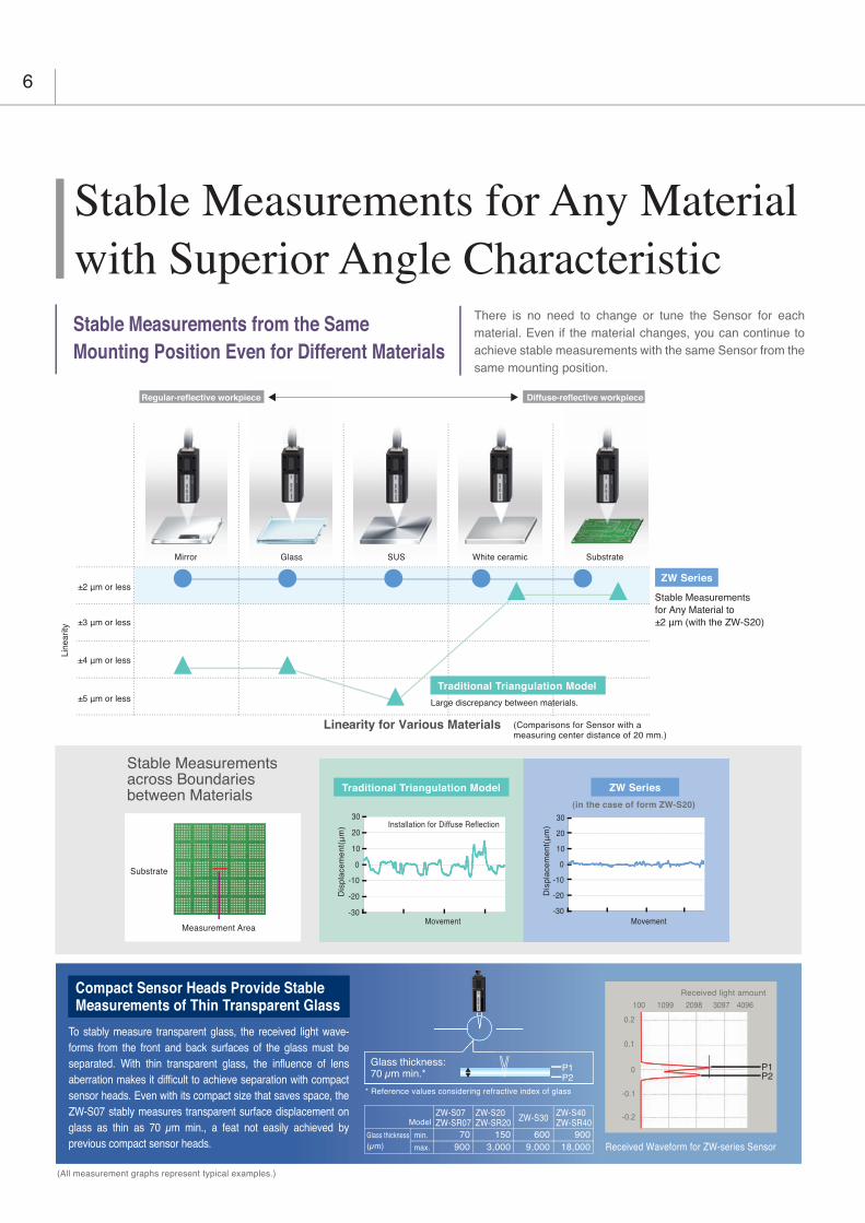
Stable Measurements from the Same Mounting Position Even for Different Materials
There is no need to change or tune the Sensor for each material. Even if the material changes, you can continue to achieve stable measurements with the same Sensor from the same mounting position.
Stable Measurements for Any Material with Superior Angle Characteristic
ZW Series
GlassMirror SUS White ceramic SubstrateSubstrateWhite ceramicSUSGlassMirror
Line
arity
±2 μm or less
±3 μm or less
±4 μm or less
±5 μm or less
Stable Measurements for Any Material to ±2 μm (with the ZW-S20)
Regular-reflective workpiece Diffuse-reflective workpiece
Linearity for Various Materials (Comparisons for Sensor with a measuring center distance of 20 mm.)
(in the case of form ZW-S20)
ZW Series
Traditional Triangulation Model
Traditional Triangulation Model
Large discrepancy between materials.
To stably measure transparent glass, the received light wave-forms from the front and back surfaces of the glass must be separated. With thin transparent glass, the influence of lens aberration makes it difficult to achieve separation with compact sensor heads. Even with its compact size that saves space, the ZW-S07 stably measures transparent surface displacement on glass as thin as 70 μm min., a feat not easily achieved by previous compact sensor heads.
Compact Sensor Heads Provide Stable Measurements of Thin Transparent Glass
Received Waveform for ZW-series Sensor
0.2
0.1
0
-0.2
-0.1
100 1099 2098 3097 4096
Received light amount
P1P2
-30
-20
-10
0
10
20
30
-30
-20
-10
0
10
20
30
Dis
plac
emen
t(μ
m)
Dis
plac
emen
t(μ
m)
Movement Movement
Installation for Diffuse Reflection
ZW-S07ZW-SR07
ZW-S20ZW-SR20 ZW-S30 ZW-S40
ZW-SR4070
900150 900600
9,0003,000 18,000
Glass thickness: 70 μm min.*
P1P2
* Reference values considering refractive index of glass
Model
Glass thickness(μm)
min.
max.

Further Benefits of Confocal PrincipleNo Discrepancy in the Measurement PointWith triangulation, the measurement position and spot size vary with
the height. This means there are times when the position cannot be
measured with high resolution due to warping and inclination. With
the confocal principle used for the ZW Series, the measurement point
remains the same at any position in the measuring range so that precise measurements can always be made.
Measurement in Confined SpacesWhen the triangulation sensor measures the inside of a narrow tube
or the height of a small depression, the wall often obstructs the
reflected light, and the orientation of the sensor and workpiece must
be adjusted many times. The ZW Series using the confocal principle
can measure the points in narrow spaces or small objects, without
changing its installation orientation, because the emitted light and
reflected light are positioned along the same axis.
Superior Angle Characteristic
When measuring an object that has a mirror-like surface with traditional triangulation, performance is greatly reduced depending on the angle of the Sensor.When many Sensors are used for height control during glass conveyance, the angles of the Sensors must be adjusted with high precision during setup. The confocal Sensor ZW series enables high-resolution measure-ments without strict angle adjustment. This results in reduction of cost and space for the adjusting jig and time for adjustment.
* This is not a guaranteed value.
Refer to Characteristic Data (P23)
for typical examples.
Angle characteristic
±8° *
7
Height Control during Glass Conveyance
Positioning of a Lens Module
Traditional Triangulation Model
With triangulation, even if the angle is adjusted with high precision during
the setup of the Sensor, stable measurement results are difficult to obtain
when the measurement object is warped or inclined.
ZW-series Sensors operate on the confocal principle, so high-
resolution measurements are possible regardless of inclination and
warping of the measurement object.
ZW Series
30
20
10
0
-10
-20
-30-1 0 10.5-0.5
30
20
10
0
-10
-20
-30-1 0 10.5-0.5
(Sensor: ZW-S20)
Err
or (μ
m)
Err
or (μ
m)
Distance (mm) Distance (mm)
Measurement is not possible.
Measurement is not possible.
+4°
+2°
+1.5°
0°
-1.5°
-2°
-4°
+4°
+2°
+1.5°
0°
-1.5°
-2°
-4°
ZW SeriesTraditional Triangulation Model
Measurement position varies with the height
No discrepancy in the measurement position
Failure to measure due to obstruction of the reflected light by the wall.
The reflected light is not obstructed by the wall.

8
To ensure high-resolution measurements with normal sensors, coun-termeasures must be implemented to protect the sensor from the elec-tromagnetic noise that is emitted by any nearby devices.The ZW-series Sensor Heads, however, contain no electronic parts to enable stable measurements even near power sections. Also, the Fiber Cable that connects the Sensor Head to the Controller can be placed near power lines and other cables that emit noise without affecting operation.
Robust Sensor Head Structure
No Noise
No electronic parts are used in the ZW-series Sensor Heads or Fiber Cables, so they give off no electromagnetic noise. You can therefore use them reliably together with other devices.
Not Affected by Noise
No Noise Emission
ZW SeriesTraditional Triangulation Model
No Noise Emitted.Electromagnetic noise is emitted from the sensor and from cables.
riangulation ModelTraditional Tr
Electromam gnegnetictic nooiseis is emitted frothe sensor and from cables.
riangulation Mode
omElectromaomagnegnetitictic nnoiseise iis emitted fro No
Fiber Cable
No electronic parts.
Changes in Measurement Values Caused by Noise
Measurements are not affected by noise and remain stable.
ZW SeriesTraditional Triangulation Model
Time
Measurement value
Noise waveform
Measurement value
Noise waveform
Time
Electronic parts
Substrate Height Inspection
Reduced Work for EMC Countermeasures

9
No Electronic PartsDisplacement sensors are often installed in moving applications and other installations that are subject to vibration. It is important that they can withstand this type of requirement. The ZW series Sensor Heads are designed for this type of environment, they have no electronic parts or PCB's that a standard triangulation sensor contains. The reduction of parts to lenses and fiber cables reduces the maintenance requirements, and the LED light source also eliminates the standard safety measures required for lasers.
An LED is used in place of a laser for the light source to eliminate the need for safety measures.
No Heat Generation
In high-resolution machine control, the heat generated by a sensor head can adversely affect nearby equipment and cause the error to increase. The ZW-series Sensor Heads, however, generate no heat and therefore do not affect nearby equipment. You can also install many Sensor Heads side by side and still be sure of reliable operation.
ZW SeriesTraditional Triangulation Model
Change in Temperature after 1.5 Hours of Operation
+0℃+2℃
ZW SeriesTraditional Triangulation Model
No electronic parts.
Special set of lenses that require no drive system.
SpecialensesrequiresystemElectronic parts
Laser diode
No electronic parts in the Sensor Head.
Electric circuits and the light source are
contained in the Controller.
Reduced Work in Thermal Design
Reduced Maintenance Costs

EtherCAT can be used to connect to servo drives or encoder input slaves to quickly get the position coordinates and ZW displacement. The height information and XY position coordinates can be easily linked so that the machine control applications can increase processing precision in respect to the height and the inspection applications benefit from maintenance, such as helping to isolate errors or perform trend analysis.
Combining Height Information and Position Coordinates
EtherCAT Machine Control Network
q y g p pmachine control applications can increase processing pr
nce, such as helping to isolate errors or perform trend ana
p qposition coordinates can be eas the inspection applications be
p qsily linked so that the nefit from maintenan
Servomotor/Servo Drive
NJ/NX-Series Machine Automation Controller
SS
Measurement result Z Servo/encoder X Servo/encoder Y
Z1
Z2
Z3
Measurement point
Point 1
Point 2
Point 3
X1
X2
X3
Y1
Y2
Y3
Results of Linking with the Position Coordinates
Machine Controls Inspection Applications
Increased processing precision
No need for constant-speed
control
Isolation of errors
Trend management for specific positions
The EtherCAT high-speed open network was optimized for machine control. The ZW-series Sensors are the first OMRON Displacement Sensors with EtherCAT to provide a highly efficient design for high-precision machine control applications that use measurement results to control machine operation.
10

With previous digital (serial) outputs through Ethernet or RS-232C, the response period for measurement commands was both incon-sistent and slow, making them unsuitable for realtime control. With EtherCAT, a constant period as short as 500 μs enables continuous digital (serial) outputs so that the overall workpiece height information can be mapped at high speed.
Long-distance Wiring: 100 m
You can use EtherCAT to connect slaves that are up to 100 m apart. With digital communications, error does not occur due to the influences of ambient noise. This solves the previous problems with analog output methods, such as the inability to support long-distance transmissions and noise countermeasures, and enables reliable installation in previously difficult large-scale machines.
Flexible Wiring for Machines
Tracing Machine Movement
You can develop, test, and adjust devices that are connected via EtherCAT with just one Support Software package. The Automation Software Sysmac Studio allows you to creatively design your controls. You can see the entire range from sensing to motion control to reduce the number of steps required to commission the system or to aid in troubleshooting. There are also plenty of offline features to debug signal control programming. You can also simulate machine operation before actual application onsite.
Fewer Steps in System Commissioning
Data Trace Debugging Control Programming
High-speed Digital Output Shorter Machine Takt Times
EtherCAT Output for ZW-series SensorPrevious Serial Output
Measurement Commands
4 ms or longer
4 ms or longer
4 ms or longer
Communi-cations
Communi-cationsProcessing Output
Communications CommunicationsProcessing Output
Communi-cations
Communi-cationsProcessing Output
8 Times Faster Than OMRON’s Previous Models
-Sysmac is a trademark or registered trademark of OMRON Corporation in Japan and other countries for OMRON factory automation products.
-Windows is registered trademarks of Microsoft Corporation in the USA and other countries.
-Other company names and product names in this document are the trademarks or registered trademarks of their respective companies.
-Microsoft product screen shot(s) reprinted with permission from Microsoft Corporation.
Note: Sysmac Studio version 1.05 or higher is required for these software interface features described.
Measurement values are output continuously at a fixed period that is as short as 500 μs.
The outputs for command inputs required 5 ms or longer and were not consistent.
Output OutputOutput
Continuous outputs at a period
that is as short as 500 μs.
11

12
Multipoint Measurement with EtherCAT Concurrency
With previous parallel I/O, manual wiring was required for dozens of points, and it was necessary to take sufficient caution to avoid sources of noise. This required extensive time to use many Displacement Sensors in a row. With EtherCAT, all you have to do is connect two lines for each Controller.
Reduced Wiring: Only Two Cables
You can set up all of the slaves that are connected via EtherCAT with just the Automation Software Sysmac Studio. Even when you combine many Sensors, you can copy setup data to effectively integrate setup work or you can easily program calculations between the Sensors.
One Software
ZW SeriesPreviously
NJ/NX-Series MachineAutomation Controller
Servomotor/Servo Drive
EtherCAT communications provide both high speed and time-consistent performance so that integrated controls for Sensors and other slaves can be achieved in realtime. Even for multipoint measurements for Displacement Sensor applications, the following advantages are provided.
Dozensof
Cables
OnlyTwo
Cables
Sysmac Studio
Efficient Setup of Measurement Conditions for Many Sensors
Easy Programming of Thickness Calculations
Sensor 1
Sensor 2
Increased efficiency in copying setups
Thickness measurements of
sheets for lithium ion batteries.
Fewer Steps in System Design
Less Wiring for Many Sensors

13
The highly precise synchronization performance of EtherCAT reduces the time error in measurements between different Sensors to 1 μs or less. Synchronous measurement is useful when measurements must be made with more than one Sensor at the same time, such as measurements from both sides of a sheet or inclination control of a substrate.
Synchronous Measurements Fewer Thickness Errors due to Vibration
Vibration that occurs during measurements taken at different time causes the output thickness to be larger than normal.
The thickness includes error.
Measurements taken at different times.
SynchronizedThe correc t thickness is measured wi thout being inf luenced by v ibrat ion.
Thickness
gnt
ss g s
When Sensors are installed in a row to continuously log sheet height, nonsynchro-
nous measurements can cause offsets in the lateral measurement positions. With
synchronous measurements using EtherCAT, you can continuously log sheet height
with all of the Sensors at the same lateral position.
ZW: Synchronized with EtherCATPreviously: Not Synchronized
Continuous Measurements of Sheets without Position Offset
Previously
Z W
Not Synchronized
Synchronized with EtherCAT
Thickness measurements of Thickness measurements of
sheets for lithium ion batteries.sheets for lithium ion batteries.
Thickness measurements of
sheets for lithium ion batteries.

The OCFL module contains a special lens set developed by OMRON that changes the focal point for each color (i.e., wavelength) of white light.The spot diameter is the same at any position within the measuring range. It does not change the way it does for a triangula-tion. High-precision lens manufacturing technology has allowed us to achieve a lens structure that is extremely small and that also does not require a drive mechanism.
*OCFL : Omron Chromatic Focus Lens
Confocal point
White light
lens structure tand that also dmechanism.
*OCFL : Omron Ch
To achieve a compact Sensor Head and high-resolution measurements, the ZW Series uses a white light confocal principle to detect objects. This principle is described below.
Based on the confocal principle, the emitted light and received light are positioned along the same axis. Light is received only when it is focused on the measurement object, allowing the height to be calculated. Unlike triangulation, the received light waveform is not disrupted by the material or inclination of the measurement object. The received light waveform is always stable, which enables high-resolution measurements.
Confocal Light Emission and Reception
The white light from the LED is focused at different points for each color (i.e., wavelength) due to a special set of lenses in the OCFL module in the Sensor Head. As a result, only the color of light that is focused on the measurement object is returned, allowing the distance from the Sensor Head to the measurement object to be calculated based on the color of the reflected light. The Sensor Head contains the special set of lenses that separates white light into different colors and the Controller contains the white LED light source, and the spectroscope and processor that convert the color of the reflected light to a distance. There is no needs for a lens drive mechanism or electronic parts in the Sensor Head, even though they were considered to be standard in previous confocal models. This achieves a much more compact design and much greater immunity to noise than triangulation models and or previous confocal models.
The reflected light is focused at the same point as the emitted light.The reflected light becomes the received light signal.
White Light Separation into Colors with Different Wavelengths at Emission
Emitted light
Reflected light
White
Confocal principle
HighZERO
ENABLE
ROM
USB
RS232C
PA
RA
LLEL
HEAD
Pass
Low 100.300100.250
White light
OCFL Module
The height is detected based on the wavelength.
Distance
NEAR
FAR Amount of received light
Colors are separated along the height direction.
Fiber Cable
spectroscopeWhite LED light source
Receiver
The reflected light of the wavelength that was focused on the surface of the measurement object passes through the fiber and the spec-troscope in the Controller converts the wave-length to a distance.
Processor
Object Located at Focal Point Inclination and Differences in Materials
OCFL Module
Patent Pending
Light emission point
Focal point
Focal point
Light is not received.
Focal point
=
Focal point
=
Light emission point
Light emission
point
Reflected light is not received because the reflected light is not focused at the light emis-sion point.
Even if the measurement object is inclined or contains different materials, the reflected light will be focused at the light emission point as long as the measure-ment object is at the focal point.
Object Not Located at Focal Point
The height is calculated from the position at which the reflected light was received.
Robust Sensor Head Structure
14

Triangulation
Normal Confocal Principle
Triangulation measures the height of an object based on the position of the spot on a receiver (CCD or CMOS). The peak, center of gravity, and other features are calculated from the received light waveform to reduce error, but in principle, the received waveform is offset or disrupted due to differences in materials or inclination. This results in measurement error.
If the measurement object is in-clined, the received waveform is offset or disrupted due to the ef-fects of aberration. This results in measurement error.
Different materials have different reflection factors. This disrupts the waveform that is received on the receiver.The peak in the waveform or the center of gravity are used to calculate the height, but error will remain in the measurement results.
In a normal confocal model, a stage and lens are driven vertically to change the focal point. This requires a more complex struc-ture, and the large number of parts interferes with downsizing. The use of a laser beam increases the chances of interference, and the received light waveform can be disrupted by the surface conditions within the small spot on the measurement object.
FAR
FAR
NEAR
NEAR
FARNEAR
Reciever
Receiver
Emission lens
Reception lens
Laser diode
Light Reception for Inclination
Light Reception for Different Materials
Receiver
Waveform disrupted
Waveform disrupted
Ideal waveform
Ideal waveform
Laser diode
Receiver
Lens
+
Lens drive circuit
Pinhole
Stage
Move the stage
and lens vertically.
Problems with Previous Models
Processor
Drive processor
15

16
System Configuration
Sysmac Studio Standard EditionSYSMAC-SE20@@
Machine Automation Controller NJ/NX/NY series
Setting Software
Sysmac StudioMeasurement Sensor EditionSYSMAC-ME00@L
Setting Software
Basic Configuration
Sensor HeadZW-S@@@
Calibration ROM(included with Sensor Head)
ControllerZW-CE1@
EtherCAT Cable(RJ45/RJ45)
EtherCAT Cable(RJ45/RJ45)
EtherCAT Cable(RJ45/RJ45)
Ethernet *2/USB
EtherCAT Master
Basic Configuration
Sensor HeadZW-S@@@
Calibration ROM(included with Sensor Head)
Controller *1ZW-CE1@
Switching Hubs
Control PLC
EtherCAT connections
Analog, EtherNet/IP, Ethernet, RS-232C and Parallel connections
*1 Controllers with binary outputs are also available (ZW-C10T/-C15T).Please contact your OMRON sales representative for details.
*2 Prepare commercially available Ethernet cable satisfying the following requirements:• Category 5e or more, 30 m or less• RJ45 connector (8-pin modular jack)• For direct connection: Select cross cable.• For connection through an industrial switching hub: Select straight cable.
Smart Monitor ZWZW-SW101
or
Analog, RS-232C and Parallel
EtherNet/IP *2, Ethernet *2
EtherCAT Cable(Select the cable that matches the Slave's connector.)
Other EtherCAT Slaves

17
Order Information
●Controller with EtherCAT
Note: Controllers with binary outputs are also available (ZW-C10T/-C15T). Please contact your OMRON sales representative for details.
●Cable
* A parallel cable for Controllers with binary outputs is also available (ZW-XCP2). Please contact your OMRON sales representative for details.
●Automation Software Sysmac StudioPlease purchase a DVD and required number of licenses the first time you purchase the Sysmac Studio. DVDs and licenses are available individually. Each model of licenses does not include any DVD.
*1. Multi licenses are available for the Sysmac Studio (3, 10, 30, or 50 licenses).*2. ZW-series is supported by Sysmac Studio version 1.05 or higher.*3. The Setting Software Smart Monitor ZW is also available (ZW-SW101). Please contact your OMRON sales representative for details.
●Accessories
Note: Place orders in units of boxes (contacting 10 units).
Appearance Power supply Output type Model
DC24VNPN ZW-CE10T
PNP ZW-CE15T
Appearance Item Cable length Model
Sensor Head - Controller Extension Fiber Cable (flexible cable) (Fiber Adapter ZW-XFC provided)
2m ZW-XF02R5m ZW-XF05R10m ZW-XF10R20m ZW-XF20R30m ZW-XF30R
Fiber Adapter (between Sensor Head pre-wired cable and Extension Fiber Cable)
⎯ ZW-XFC
Parallel cable for ZW-CE1@T 32-pole*(included with Controller ZW-CE1@T) 2m ZW-XCP2E
RS-232C Cable for personal computer 2m ZW-XRS2
RS-232C Cable for PLC/programmable terminal 2m ZW-XPT2
Product name Specifications Model StandardsNumber of licenses Media
Sysmac StudioStandard EditionVer.1.@@ *2
The Sysmac Studio is the software that provides an integrated environment for setting, programming, debugging and maintenance of machine automation controllers including the NJ/NX-series CPU Units, NY-series Industrial PC, EtherCat Slave, and the HMI.
Sysmac Studio runs on the following OS.Windows 7 (32-bit/64-bit version)/Windows 8 (32-bit/64-bit version)/Windows 8.1 (32-bit/64-bit version)/Windows 10 (32-bit/64-bit version)
This software provides functions of the Measurement Sensor Edition. Refer to Sysmac Catalog (P072) for details such as supported models and functions.
⎯(Media only) DVD SYSMAC-SE200D ⎯
1 license*1 ⎯ SYSMAC-SE201L ⎯
Sysmac StudioMeasurement Sensor EditionVer.1.@@ *3
Sysmac Studio Measurement Sensor Edition is a limited license that provides selected functions required for ZW-seriesDisplacement Sensor settings.Because this product is a license only, you need the Sysmac Standard Edition DVD media to install it.
1 license ⎯ SYSMAC-ME001L ⎯
3 license ⎯ SYSMAC-ME003L ⎯
Item ModelFiber Connector Cleaner ZW-XCL
Sensor Head
40302070
ZW-S20 2M ZW-S30 2M ZW-S40 2M
20±1mm40µm dia.0.25µm
ZW-S07 2M
7±0.3mm18µm dia.0.25µm
30±3mm60µm dia.0.25µm
40±6mm80µm dia.0.25µm
ZW-SR07 2M
7±0.3mm18µm dia.0.25µm
ZW-SR20 2M
20±1mm40µm dia.0.25µm
ZW-SR40 2MZW-S20 0.3M ZW-S30 0.3M ZW-S40 0.3MZW-S07 0.3M ZW-SR07 0.3M ZW-SR20 0.3M ZW-SR40 0.3M
40±6mm80µm dia.0.25µm
20±1mm30±3mm
40±6mm
20±1mm
40±6mm
7±0.3mm 7±0.3mm
Straight type Right-angle type
Measuring rangeSpot diameterStatic resolution
Model

18
●Recommended EtherCAT Communications CablesUse Straight STP (shielded twisted-pair) cable of category 5 or higher with double shielding (braiding and aluminum foil tape) for EtherCAT.
●Cabel with Connectors
Note: For details, refer to Cat.No.G019.*1. Standard type cables length 0.2, 0.3, 0.5, 1, 1.5, 2, 3, 5, 7.5, 10, 15 and 20 m are available.
Rugged type cables length 0.3, 0.5, 1, 2, 3, 5, 10 and 15 m are available.*2. The lineup features Low Smoke Zero Halogen cables for in-cabinet use and PUR cables for out-of-cabinet use.*3. Cables colors are available in blue, yellow, or Green.
●Cables / ConnectorsWire Gauge and Number of Pairs: AWG24, 4-pair Cable
* We recommend you to use above cable and connector together.
Wire Gauge and Number of Pairs: AWG22, 2-pair Cable
Note: Connect both ends of cable shielded wires to the connector hoods.* We recommend you to use above cable and connector together.
●Industrial switching hubs for Ethernet
Note: Industrial switching hubs are cannot be used for EtherCAT.
●EtherCAT junction slaves
Note: 1. Please do not connect EtherCAT junction slave with OMRON position control unit, Model CJ1W-NC@81/@82. 2. EtherCAT junction slaves cannot be used for EtherNet/IPTM and Ethernet.
Item Appearance Recommended manufacturer Cable length(m) *1 ModelStandard typeCable with Connectors on Both Ends (RJ45/RJ45)Wire Gauge and Number of Pairs: AWG26, 4-pair CableCable Sheath material: LSZH *2Cable color: Yellow *3
OMRON
0.3 XS6W-6LSZH8SS30CM-Y0.5 XS6W-6LSZH8SS50CM-Y1 XS6W-6LSZH8SS100CM-Y2 XS6W-6LSZH8SS200CM-Y3 XS6W-6LSZH8SS300CM-Y5 XS6W-6LSZH8SS500CM-Y
Rugged typeCable with Connectors on Both Ends (RJ45/RJ45)Wire Gauge and Number of Pairs: AWG22, 2-pair Cable
OMRON
0.3 XS5W-T421-AMD-K0.5 XS5W-T421-BMD-K1 XS5W-T421-CMD-K2 XS5W-T421-DMD-K5 XS5W-T421-GMD-K10 XS5W-T421-JMD-K
Rugged typeCable with Connectors on Both Ends (M12 Straight/RJ45)Wire Gauge and Number of Pairs: AWG22, 2-pair Cable
OMRON
0.3 XS5W-T421-AMC-K0.5 XS5W-T421-BMC-K1 XS5W-T421-CMC-K2 XS5W-T421-DMC-K5 XS5W-T421-GMC-K10 XS5W-T421-JMC-K
Rugged typeCable with Connectors on Both Ends (M12 Right-angle/RJ45)Wire Gauge and Number of Pairs: AWG22, 2-pair Cable
OMRON
0.3 XS5W-T422-AMC-K0.5 XS5W-T422-BMC-K1 XS5W-T422-CMC-K2 XS5W-T422-DMC-K5 XS5W-T422-GMC-K10 XS5W-T422-JMC-K
Item Appearance Recommended manufacturer Model
Cables⎯ Hitachi Metals, Ltd. NETSTAR-C5E SAB 0.5 × 4P *⎯ Kuramo Electric Co. KETH-SB *⎯ SWCC Showa Cable Systems Co. FAE-5004 *
RJ45 Connectors ⎯ Panduit Corporation MPS588-C *
Item Appearance Recommended manufacturer Model
Cables ⎯ Kuramo Electric Co. KETH-PSB-OMR *⎯ JMACS Japan Co.,Ltd. PNET/B *
RJ45 Assembly Connector OMRON XS6G-T421-1 *
Appearance Number of ports Failure detection Current consumption Model
3 None 0.22A W4S1-03B
5None
0.22AW4S1-05B
Supported W4S1-05C
Appearance Number of ports Power supply voltage Current consumption Model
3
20.4 to 28.8 VDC(24 VDC -15 to 20%)
0.08A GX-JC03
6 0.17A GX-JC06

19
Specifications●Sensor Head
*1. Capacity value when Omron standard mirror surface target is measured at the measurement center distance as the average of 4,096 times.*2. Material setting for the Omron standard mirror surface target: Error from an ideal straight line when measuring on mirror surface.
The reference values for linearity when targets to measure other than the above are as in the table below.
*3. Capacity value defined by 1/e2 (13.5%) of the center optical intensity in the measured area.*4. Temperature characteristic at the measurement center distance when the Sensor Head and the target are fastened with an aluminum jig and the Sensor Head and
the Controller are set in the same temperature environment.
●Automation Software Sysmac Studio System Requirements
*1. Sysmac Studio Operating System Precaution: System requirements and hard disk space may vary with the system environment.*2. The following restrictions apply when Sysmac Studio is used with Microsoft Windows Vista or Windows 7.
Some Help files cannot be accessed.The Help files can be accessed if the Help program distributed by Microsoft for Windows (WinHlp32.exe) is installed. Refer to the Microsoft homepage listed below or contact Microsoft for details on installing the file. (The download page is automatically displayed if the Help files are opened while the user is connected to the Internet.)http://support.microsoft.com/kb/917607/en-us
*3. Refer to the hardware manual for your Controller for hardware connection methods and cables to connect the computer and Controller.
●Setting Software Smart Monitor ZW ZW-SW101System Requirements
Item ZW-S07 ZW-S20 ZW-S30 ZW-S40 ZW-SR07 ZW-SR20 ZW-SR40Measuring center distance 7 mm 20 mm 30 mm 40 mm 7 mm 20 mm 40 mmMeasuring range ±0.3 mm ±1 mm ±3 mm ±6 mm ±0.3 mm ±1 mm ±6 mmStatic resolution *1 0.25 μm 0.25 μm 0.25 μm 0.25 μm 0.25 μm 0.25 μm 0.25 μmLinearity *2 ±0.8 μm ±1.2 μm ±4.5 μm ±7.0 μm ±1.1 μm ±1.6 μm ±9.3 μm
Spot diameter *3Near 20 μm dia. 45 μm dia. 70 μm dia. 90 μm dia. 20 μm dia. 45 μm dia. 90 μm dia.Center 18 μm dia. 40 μm dia. 60 μm dia. 80 μm dia 18 μm dia. 40 μm dia. 80 μm diaFar 20 μm dia. 45 μm dia. 70 μm dia. 90 μm dia 20 μm dia. 45 μm dia. 90 μm dia
Measuring cycle 500 μs to 10 msApplicable sensor controller ZW-C1@@@/-CE1@@Operating ambient illumination Illumination on object surface 10,000 lx or less: incandescent lightAmbient temperature range Operating: 0 to 50°C, Storage: −15 to 60°C (with no icing or condensation)Ambient humidity range Operating and storage: 35% to 85% (with no condensation)Degree of protection IP40 (IEC60529)Vibration resistance (destructive) 10 to 150 Hz, 0.35 mm single amplitude, 80 min each in X, Y, and Z directionsShock resistance (destructive) 150 m/s2 3 times each in six directions (up/down, left/right, forward/backward)Temperature characteristic *4 0.6 μm/ °C 1.5 μm/ °C 2.8 μm/ °C 4.8 μm/ °C 0.6 μm/ °C 1.5 μm/ °C 4.8 μm/ °C
MaterialsCase: aluminum die-castFiber cable sheat: PVCCalibration ROM: PC
Fiber cable length 0.3 m, 2 m (Flex-resistant cable)Fiber cable minimum bending radius 20 mmInsulation resistance (Calibration ROM) Between case and all terminals: 20 MΩ (by 250 V megger)Dielectric strength (Calibration ROM) Between case and all terminals: 1,000 VAC, 50/60 Hz, 1 minWeight Approx. 105 g (Chassis, fiber cable total)Accessories included with sensor head Instruction sheet, Fixing screw (M2) for Calibration ROM, Precautions for correct use
Item ZW-S07 ZW-S20 ZW-S30 ZW-S40 ZW-SR07 ZW-SR20 ZW-SR40Glass ±1.0 μm ±1.2 μm ±4.5 μm ±7.0 μm ±1.1 μm ±1.6 μm ±9.3 μmSUS BA ±1.2 μm ±1.4 μm ±5.5 μm ±8.5 μm ±1.2 μm ±1.8 μm ±9.3 μmWhite ceramic ±1.6 μm ±1.7 μm ±6.4 μm ±9.5 μm ±1.6 μm ±1.9 μm ±11.0 μm
Item Requirement
Operating system (OS) *1 *2Windows XP (Service Pack 3 or higher, 32-bit version)/Windows Vista (32-bit version)/Windows 7 (32-bit/64-bit version)/Windows 8 (32-bit/64-bit version)/Windows 8.1 (32-bit/64-bit version)/Windows 10 (32-bit/64-bit version)
CPU Windows computers with Celeron 540 (1.8 GHz) or faster CPU.Core i5 M520 (2.4 GHz) or equivalent or faster recommended
Main memory 2 GB min.
Recommended videomemory / video card for using 3D motion trace
Video memory: 512 MB min.Video card: Either of the following video cards:• NVIDIAR GeForceR 200 Series or higher• ATI RadeonHD5000 Series or higher
Hard disk At least 1.6 GB of available space
Display XGA 1024 × 768, 16 million colors.WXGA 1280 × 800 min. recommended
Disk drive DVD-ROM driveCommunications ports USB port corresponded to USB 2.0, or Ethernet port *3Supported languages Japanese, English, German, French, Italian, Spanish, simplified Chinese, traditional Chinese, Korean
Item Condition
Operating System(OS) Windows 7 (32 or 64-bit version)Windows XP (Service Pack3 or more, 32-bit version)
CPU Intel Pentium III, 850 MHz or more (2 GHz or more is recommended.)Main memory 1 GB or moreHard disk 50 MB or moreDisplay 1024 × 768 dots or more, 16 million colors or moreSupported languages Japanese/EnglishCommunication port Ethernet port

20
●Controller
Note: Controllers with binary outputs are also available (ZW-C10T/-C15T). Please contact your OMRON sales representative for details.
●ZW Series EtherCAT Communications Specifications
Item ZW-CE10T ZW-CE15TInput/Output type NPN PNPNumber of connected Sensor Heads 1 per ControllerApplicable sensor head ZW-S@@/-SR@@Light source for measurement White LEDSegment display
Main display 11-segment red display, 6 digitsSub-display 11-segment green display, 6 digits
LED displayStatus indicators HIGH (orange), PASS (green), LOW (orange), STABILITY (green), ZERO (green),
ENABLE (green), THRESHOLD-H (orange), THRESHOLD-L (orange), RUN (green)
EtherCAT indicators L/A IN(Link Activity IN)(green), L/O OUT(Link Activity OUT)(green), ECAT RUN(green), ECAT ERR(red)
External interface
Ethernet 100BASE-TX, 10BASE-T, No-protocol Communications (TCP/UDP), EtherNet/IPTM
EtherCAT EtherCAT-specific protocol 100BASE-TXRS-232C 115,200 bps max.Analog output terminal block
Analog voltage output (OUT1V) -10 V to +10 V, output impedance: 100 Ω
Analog current output (OUT1A) 4 mA to 20 mA, maximum load resistance: 300Ω
32-poleextensionconnector
Judgment output (HIGH1/PASS1/LOW1)
Transistor output systemOutput voltage: 21.6 to 30 VDCLoad current: 50 mA or lessResidual voltage when turning ON: 1.2 V or lessLeakage voltage when turning OFF: 0.1 mA or les
BUSY output (BUSY1)ALARM output (ALARM1)ENABLE output (ENABLE)LED OFF input (LED OFF1) DC input system
Input voltage: 24 VDC ⋅10% (21.6 to 26.4 VDC)Input current: 7 mA Typ. (24 VDC)Voltage/Current when turning ON: 19 V/3 mA or moreVoltage/Current when turning OFF:5 V/1 mA or less
ZERO RESET input (ZERO)TIMING output (TIMING1)RESET output (RESET1)
Bank
Selected bank output(BANK_OUT 1 to 3)
Transistor output systemOutput voltage: 21.6 to 30 VDCLoad current: 50 mA or lessResidual voltage when turning ON: 1.2 V or lessLeakage voltage when turning OFF: 0.1 mA or less
Selected bank input(BANK_SEL 1 to 3)
DC input systemInput voltage: 21.6 to 26 VDCInput current: 7 mA Typ. (24 VDC)Voltage/Current when turning ON: 19 V/3 mA or moreVoltage/Current when turning OFF:5 V/1 mA or less
Main functions
Exposure time Auto/ManualMeasuring cycle 500 μs to 10 msMaterial setting Standard/Mirror/Diffusion surfacesMeasurement Item Height/Thickness/CalculationFiltering Median/Average/Differentiation/High pass/Low pass/Band passOutputs Scaling/Different holds/Zero reset/Logging for a measured value
Display Measured value/Threshold value/Analog output voltage or current value/Judgment result/Resolution/Exposure time
Number of configurable banks Max. 8 banksTask process Multi-task (up to 4 tasks per bank)
System Save/Initialization/Display measurement information/Communication settings/Sensor Head calibration/Key-lock/Trigger-key input
Ratings
Power supply voltage 21.6 to 26.4 VDC (including ripple)Current consumption 600 mA max.Insulation resistance Across all lead wires and controller case: 20 MΩ(by 250 V megger)Dialectic strength Across all lead wires and controller case: 1,000 VAC, 50/60 Hz, 1 min.
Environmental
Degree of protection IP20(IEC60529)Vibration resistance (destructive) 10 to 55 Hz, 0.35-mm single amplitude, 50 min each in X, Y, and Z directionsShock resistance (destructive) 150 m/s2, 3 times each in six directions (up/down, left/right, forward/backward)
Ambient temperature Operating: 0 to 40°CStorage:-15 to 60°C (with no icing or condensation)
Ambient humidity Operating and storage: 35% to 85% (with no condensation)
Grounding D-type grounding (Grounding resistance of 100 Ω or less)Note: For conventional Class D grounding
Materials Case: PCWeight Approx. 750 g (main unit only), Approx. 150 g (Parallel Cable)Accessories included with controller Instruction sheet,Member registration sheet, Parallel cable ZW-XCP2E
Item SpecificationCommunications standard IEC61158 Type12Physical layer 100BASE-TX(IEEE802.3)
ConnectorsRJ45 × 2ECAT IN: EtherCAT inputECAT OUT: EtherCAT output
Communications media Category 5 or higher (cable with double, aluminum tape and braided shielding) is recommended.Communications distance Distance between nodes: 100 m max.Process data Variable PDO mappingMailbox (CoE) Emergency messages, SDO requests, SDO responses, and SDO informationDistributed clock Synchronization in DC mode.LED display L/A IN (Link/Activity IN) × 1, AL/A OUT (Link/Activity OUT) × 1, AECAT RUN × 1, AECAT ERR × 1

21
Characteristic data (typical examples)Linearity Characteristic by MaterialsStraight type
ZW-S07
ZW-S20
ZW-S30
ZW-S40
Measuring center distance 0
Material setting: Normal Material setting: Mirror surface Material setting: Diffusion surface
Err
or [µ
m]
-5
-4
-3
-2
-1
0
1
2
3
4
5
Distance [mm]-0.3 -0.2 -0.1 0 0.1 0.2 0.3
Err
or [µ
m]
-5
-4
-3
-2
-1
0
1
2
3
4
5
Distance [mm]-0.3 -0.2 -0.1 0 0.1 0.2 0.3
Err
or [µ
m]
-5
-4
-3
-2
-1
0
1
2
3
4
5
Distance [mm]-0.3 -0.2 -0.1 0 0.1 0.2 0.3
White ceramicMirror
GlassSUS BA
White ceramic
Mirror
GlassSUS BA
Distance [mm]
Err
or [µ
m]
10
8
6
4
2
0
-2
-4
-6
-8
-10-1 -0.8 -0.6 -0.4 -0.2 0 0.2 0.4 0.6 0.8
Distance [mm]
Material setting: Normal Material setting: Mirror surface
Err
or [µ
m]
Material setting: Diffusion surface
Distance [mm]
Err
or [µ
m]
1 -1 -0.8 -0.6 -0.4 -0.2 0 0.2 0.4 0.6 0.8 1
10
8
6
4
2
0
-2
-4
-6
-8
-10-1 -0.8 -0.6 -0.4 -0.2 0 0.2 0.4 0.6 0.8 1
10
8
6
4
2
0
-2
-4
-6
-8
-10
Mirror
GlassSUS BA
White ceramic
Mirror
GlassSUS BA
White ceramic
Material setting: Normal Material setting: Mirror surface Material setting: Diffusion surface
20
16
12
8
4
0
-4
-8
-12
-16
-20
Err
or [µ
m]
20
16
12
8
4
0
-4
-8
-12
-16
-20
Err
or [µ
m]
-3 -2.5 -2 -1.5 -1 -0.5 0.50 1 1.5 2 2.5
Distance [mm]3 -3 -2.5 -2 -1.5 -1 -0.5 0.50 1 1.5 2 2.5
Distance [mm]3
20
16
12
8
4
0
-4
-8
-12
-16
-20
Err
or [µ
m]
-3 -2.5 -2 -1.5 -1 -0.5 0.50 1 1.5 2 2.5
Distance [mm]3
White ceramicMirror
GlassSUS BA
White ceramic
Mirror
GlassSUS BA
Distance [mm]
Err
or [µ
m]
Material setting: Normal Material setting: Mirror surface30
25
20
15
10
5
0
-5
-10
-15
-20
-25
-30-6 -5 -4 -3 -2 -1 0 1 2 3 4 5 6
Distance [mm]
Err
or [µ
m]
Material setting: Diffusion surface
Distance [mm]
Err
or [µ
m]
Mirror
GlassSUS BA
White ceramic
-6 -5 -4 -3 -2 -1 0 1 2 3 4 5 6
30
25
20
15
10
5
0
-5
-10
-15
-20
-25
-30
Mirror
GlassSUS BA
-6 -5 -4 -3 -2 -1 0 1 2 3 4 5 6
30
25
20
15
10
5
0
-5
-10
-15
-20
-25
-30
White ceramic

22
Right-angle type
ZW-SR07
ZW-SR20
ZW-SR40
Measuring center distance 0
+
-
5
4
3
2
1
0
-1
-2
-3
-4
-5
Err
or [µ
m]
Err
or [µ
m]
Err
or [µ
m]
-0.3 0.3-0.2 0.2-0.1 0.10
Distance [mm] Distance [mm] Distance [mm]
5
4
3
2
1
0
-1
-2
-3
-4
-5-0.3 0.3-0.2 0.2-0.1 0.10
5
4
3
2
1
0
-1
-2
-3
-4
-5-0.3 0.3-0.2 0.2-0.1 0.10
White ceramic
Material setting: Normal Material setting: Mirror surface Material setting: Diffusion surface
Mirror
GlassSUS BA
White ceramic
Mirror
GlassSUS BA
10
8
6
4
2
0
-2
-4
-6
-8
-10-1 1-0.8 0.8-0.6 0.6-0.4 0.4-0.2 0.20
10
8
6
4
2
0
-2
-4
-6
-8
-10-1 1-0.8 0.8-0.6 0.6-0.4 0.4-0.2 0.20
10
8
6
4
2
0
-2
-4
-6
-8
-10-1 1-0.8 0.8-0.6 0.6-0.4 0.4-0.2 0.20
Err
or [µ
m]
Err
or [µ
m]
Err
or [µ
m]
Distance [mm] Distance [mm] Distance [mm]
White ceramic
Material setting: Normal Material setting: Mirror surface Material setting: Diffusion surface
Mirror
GlassSUS BA
White ceramic
Mirror
GlassSUS BA
30
25
20
15
10
5
0
-5
-10
-15
-20
-25
-30-6 -5 -4 -3 -2 -1 0 1 2 3 4 5 6
30
25
20
15
10
5
0
-5
-10
-15
-20
-25
-30-6 -5 -4 -3 -2 -1 0 1 2 3 4 5 6
30
25
20
15
10
5
0
-5
-10
-15
-20
-25
-30-6 -5 -4 -3 -2 -1 0 1 2 3 4 5 6
White ceramic
Err
or [µ
m]
Err
or [µ
m]
Err
or [µ
m]
Distance [mm] Distance [mm] Distance [mm]
Material setting: Normal Material setting: Mirror surface Material setting: Diffusion surface
Mirror
GlassSUS BA
White ceramic
Mirror
GlassSUS BA

23
●Angle Characteristic *Straight type
ZW-S07
ZW-S20
ZW-S30
ZW-S40
* The above show the results after executing scaling.
Slope angle +
Slope angle −
Slope angle +
Slope angle −
Model nameplate
α direction β direction
White ceramic α direction White ceramic β direction
Err
or [µ
m]
-5
-4
-3
-2
-1
0
1
2
3
4
5
Distance [mm] -0.3 -0.15 0 0.15 0.3
Err
or [µ
m]
-5
-4
-3
-2
-1
0
1
2
3
4
5
Distance [mm] -0.3 -0.15 0 0.15 0.3
+50°
−50°0°
Slope angle+50°
−50°0°
Slope angle
Mirror β directionMirror α direction
Err
or [µ
m]
-5
-4
-3
-2
-1
0
1
2
3
4
5
Distance [mm] -0.3 -0.15 0 0.15 0.3
Err
or [µ
m]
-5
-4
-3
-2
-1
0
1
2
3
4
5
Distance [mm] -0.3 -0.15 0 0.15 0.3
+8°
−8°0°
Slope angle+8°
−8°0°
Slope angle
10
8
6
4
2
0
-2
-4
-6
-8
-10
10
8
6
4
2
0
-2
-4
-6
-8
-10
10
8
6
4
2
0
-2
-4
-6
-8
-10
+8°
−8°0°
Slope angle+50°
−50°0°
Slope angle10
8
6
4
2
0
-2
-4
-6
-8
-10
+8°
−8°0°
Slope angle+50°
−50°0°
Slope angle
Mirror β direction White ceramic β directionMirror α direction White ceramic α direction
Distance [mm] Distance [mm] Distance [mm] Distance [mm] -1 -0.5 0 -0.5 1 -1 -0.5 0 -0.5 1-1 -0.5 0 -0.5 1 -1 -0.5 0 -0.5 1
Err
or [µ
m]
Err
or [µ
m]
Err
or [µ
m]
Err
or [µ
m]
Err
or [µ
m]
20
15
10
5
0
-5
-10
-15
-20
Err
or [µ
m]
20
15
10
5
0
-5
-10
-15
-20
Err
or [µ
m]
20
15
10
5
0
-5
-10
-15
-20
Mirror α direction
+6°
−6°0°
Slope angle
Err
or [µ
m]
20
15
10
5
0
-5
-10
-15
-20
Mirror β direction
+6°
−6°0°
Slope angle
White ceramic α direction
+50°
−50°0°
Slope angle
White ceramic β direction
+50°
−50°0°
Slope angle
Distance [mm] Distance [mm] Distance [mm] Distance [mm] 0 1-1-2-3 2 3 0 1-1-2-3 2 3 0 1-1-2-3 2 3 0 1-1-2-3 2 3
White ceramic β direction30
20
10
0
-10
-6 -4 -2 0 2 4 6
-20
-30
Distance [mm]
Err
or [µ
m]
+50°
−50°0°
Slope angle
Mirror α direction30
20
10
0
-10
-6 -4 -2 0 2 4 6
-20
-30
Distance [mm]
Err
or [µ
m]
+5°
−5°
Slope angle
0°
Mirror β direction30
20
10
0
-10
-6 -4 -2 0 2 4 6
-20
-30
Distance [mm]
Err
or [µ
m]
+5°
−5°
Slope angle
0°
White ceramic α direction30
20
10
0
-10
-6 -4 -2 0 2 4 6
-20
-30
Distance [mm]
Err
or [µ
m]
+50°
−50°0°
Slope angle

24
Right-angle type
ZW-SR07
ZW-SR20
ZW-SR40
* The above show the results after executing scaling.
α direction β direction
Slope angle +
Slope angle −
Slope angle +
Slope angle −
-5
-4
-3
-2
-1
0
1
2
3
4
5
-0.3 -0.15 0 0.15 0.3-5
-4
-3
-2
-1
0
1
2
3
4
5
-0.3 -0.15 0 0.15 0.3-5
-4
-3
-2
-1
0
1
2
3
4
5
-0.3 -0.15 0 0.15 0.3
+8°
−8°0°
Slope angle
-5
-4
-3
-2
-1
0
1
2
3
4
5
-0.3 -0.15 0 0.15 0.3
+8°
−8°0°
Slope angle +50°
−50°0°
Slope angle+50°
−50°0°
Slope angle
White ceramic β direction
Distance [mm]
Err
or [µ
m]
Mirror α direction
Distance [mm]
Err
or [µ
m]
Mirror β direction
Distance [mm]
Err
or [µ
m]
White ceramic α direction
Distance [mm]
Err
or [µ
m]
-10
-8
-6
-4
-2
0
2
4
6
8
10
+8°
−8°0°
+8°
−8°0°
Slope angle Slope angle
-10
-8
-6
-4
-2
0
2
4
6
8
10
-10
-8
-6
-4
-2
0
2
4
6
8
10
-10
-8
-6
-4
-2
0
2
4
6
8
10
-1 -0.5 0.50 1-1 -0.5 0.50 1-1 -0.5 0.50 1-1 -0.5 0.50 1
−50°
−50°0°
+50°
−50°0°
White ceramic β direction
Distance [mm]
Err
or [µ
m]
Mirror α direction
Distance [mm]
Err
or [µ
m]
Mirror β direction
Distance [mm]
Err
or [µ
m]
White ceramic α direction
Distance [mm]
Err
or [µ
m]
Slope angle Slope angle
-30
-20
-10
0
10
20
30
-6 -4 -2 0 2 4 6-30
-20
-10
0
10
20
30
-6 -4 -2 0 2 4 6-30
-20
-10
0
10
20
30
-6 -4 -2 0 2 4 6-30
-20
-10
0
10
20
30
-6 -4 -2 0 2 4 6
+5°
−5°0°
Slope angle+5°
−5°0°
Slope angle+50°
−50°0°
Slope angle+50°
−50°0°
Slope angle
White ceramic β direction
Distance [mm]
Mirror α direction
Distance [mm]
Err
or [µ
m]
Mirror β direction
Distance [mm]
Err
or [µ
m]
Err
or [µ
m]
Err
or [µ
m]
White ceramic α direction
Distance [mm]

25
External Dimensions (Unit: mm)
Sensor HeadStraight type
Right-angle type
16
4
Four, 3.5 dia. (Mounting holes)
Measurement center
M (See note) M (See note)
L (See note)
Lighting andreceiving axis
Measurement endFAR
Standard fiber cable (2.0 dia.)
Standard surface
Connector
(10 dia.)
16±0.1
4±0.1
Standard surface
Mounting hole dimensions
Four, M3
Cautionlabel
MeasurementCENTER
Measurement endNEARX(See note)
(50)(42)
43±0.1
16±0.1
2412
64 (40)
43 16
24
Standard surface
ZW-S07/-S20/-S30/-S40
Note:
Model L M X
ZW-S07 7 0.3 12
ZW-S20 20 1 11.8
ZW-S30 30 3 11.7
ZW-S40 40 6 11.7
ZW-SR07/-SR20/-SR40
Note:
Model L M
ZW-SR07 7 0.3
ZW-SR20 20 1
ZW-SR40 40 6
43 16
16±0.1
(24) (64)
(23.6) (24)
(12) 43±0.1
(23.6)
(24)
(50) (42)
12
(24)
23.6
32.5
24 (40)64
L (See note)
12
8.5
24
24
12
4±0.1
16
4
16 ±0.1
Four, 3.5 dia. (Mounting holes)
Lighting andreceiving axis
Standard fiber cable (2.0 dia.)
Standard surface
Connector
(10 dia.)
Standard surface
Mounting hole dimensions
Four, M3
Cautionlabel
Standard surface
M (See note)
M (See note)
Measurement endNEAR
MeasurementCENTER
MeasurementCENTER
Measurement endFAR

26
Controller
Extension Fiber Cable
Related ManualsMan.No. Model number Manual
Z332 ZW-CE1@T Displacement Measurement Sensor ZW-CE1@T Series User's Manual
14.5
Installation holesFour, M4 depth 6.0 MAX Mounting hole dimensions
Four, 4.5 dia.40
70
43
43±0.1
70±0.1
DIN track attachment hook
6
72
12434.9
40.8
128
127.5
(10.2)
(21.4)
ZW-CE10T/-CE15T
FC connectorFiber Cable (2.0 dia.) FC connector
(10 dia.)
(50)(42)
L (See note)
(42)
ZW-XF02R/-XF05R/-XF10R/-XF20R/-XF30RNote: The following table lists cable lengths
per models.
Model Cable length L
ZW-XF02R 2 m 2,000±20
ZW-XF05R 5 m 5,000±50
ZW-XF10R 10 m 10,000±100
`ZW-XF20R 20 m 20,000±200
ZW-XF30R 30 m 30,000±300

Terms and Conditions AgreementRead and understand this catalog.
Please read and understand this catalog before purchasing the products. Please consult your OMRON representative if you have any questions or comments.
Warranties.(a) Exclusive Warranty. Omron’s exclusive warranty is that the Products will be free from defects in materials and workmanship
for a period of twelve months from the date of sale by Omron (or such other period expressed in writing by Omron). Omron disclaims all other warranties, express or implied.
(b) Limitations. OMRON MAKES NO WARRANTY OR REPRESENTATION, EXPRESS OR IMPLIED, ABOUT NON-INFRINGEMENT, MERCHANTABILITY OR FITNESS FOR A PARTICULAR PURPOSE OF THE PRODUCTS. BUYER ACKNOWLEDGES THAT IT ALONE HAS DETERMINED THAT THE PRODUCTS WILL SUITABLY MEET THE REQUIREMENTS OF THEIR INTENDED USE.
Omron further disclaims all warranties and responsibility of any type for claims or expenses based on infringement by the Products or otherwise of any intellectual property right. (c) Buyer Remedy. Omron’s sole obligation hereunder shall be, at Omron’s election, to (i) replace (in the form originally shipped with Buyer responsible for labor charges for removal or replacement thereof) the non-complying Product, (ii) repair the non-complying Product, or (iii) repay or credit Buyer an amount equal to the purchase price of the non-complying Product; provided that in no event shall Omron be responsible for warranty, repair, indemnity or any other claims or expenses regarding the Products unless Omron’s analysis confirms that the Products were properly handled, stored, installed and maintained and not subject to contamination, abuse, misuse or inappropriate modification. Return of any Products by Buyer must be approved in writing by Omron before shipment. Omron Companies shall not be liable for the suitability or unsuitability or the results from the use of Products in combination with any electrical or electronic components, circuits, system assemblies or any other materials or substances or environments. Any advice, recommendations or information given orally or in writing, are not to be construed as an amendment or addition to the above warranty.
See http://www.omron.com/global/ or contact your Omron representative for published information.
Limitation on Liability; Etc.OMRON COMPANIES SHALL NOT BE LIABLE FOR SPECIAL, INDIRECT, INCIDENTAL, OR CONSEQUENTIAL DAMAGES, LOSS OF PROFITS OR PRODUCTION OR COMMERCIAL LOSS IN ANY WAY CONNECTED WITH THE PRODUCTS, WHETHER SUCH CLAIM IS BASED IN CONTRACT, WARRANTY, NEGLIGENCE OR STRICT LIABILITY.
Further, in no event shall liability of Omron Companies exceed the individual price of the Product on which liability is asserted.
Suitability of Use.Omron Companies shall not be responsible for conformity with any standards, codes or regulations which apply to the combination of the Product in the Buyer’s application or use of the Product. At Buyer’s request, Omron will provide applicable third party certification documents identifying ratings and limitations of use which apply to the Product. This information by itself is not sufficient for a complete determination of the suitability of the Product in combination with the end product, machine, system, or other application or use. Buyer shall be solely responsible for determining appropriateness of the particular Product with respect to Buyer’s application, product or system. Buyer shall take application responsibility in all cases.
NEVER USE THE PRODUCT FOR AN APPLICATION INVOLVING SERIOUS RISK TO LIFE OR PROPERTY OR IN LARGE QUANTITIES WITHOUT ENSURING THAT THE SYSTEM AS A WHOLE HAS BEEN DESIGNED TO ADDRESS THE RISKS, AND THAT THE OMRON PRODUCT(S) IS PROPERLY RATED AND INSTALLED FOR THE INTENDED USE WITHIN THE OVERALL EQUIPMENT OR SYSTEM.
Programmable Products.Omron Companies shall not be responsible for the user’s programming of a programmable Product, or any consequence thereof.
Performance Data.Data presented in Omron Company websites, catalogs and other materials is provided as a guide for the user in determining suitability and does not constitute a warranty. It may represent the result of Omron’s test conditions, and the user must correlate it to actual application requirements. Actual performance is subject to the Omron’s Warranty and Limitations of Liability.
Change in Specifications.Product specifications and accessories may be changed at any time based on improvements and other reasons. It is our practice to change part numbers when published ratings or features are changed, or when significant construction changes are made. However, some specifications of the Product may be changed without any notice. When in doubt, special part numbers may be assigned to fix or establish key specifications for your application. Please consult with your Omron’s representative at any time to confirm actual specifications of purchased Product.
Errors and Omissions.Information presented by Omron Companies has been checked and is believed to be accurate; however, no responsibility is assumed for clerical, typographical or proofreading errors or omissions.

The 24×24×64-mm Sensor Head redefines the meaning of ultra-compact
Authorized Distributor:
In the interest of product improvement, specifications are subject to change without notice.
Cat. No. E421-E1-03Printed in Japan
0714 (0312)
© OMRON Corporation 2012-2014 All Rights Reserved.
OMRON Corporation Industrial Automation Company
OMRON ELECTRONICS LLC2895 Greenspoint Parkway, Suite 200 Hoffman Estates, IL 60169 U.S.ATel: (1) 847-843-7900/Fax: (1) 847-843-7787
Regional HeadquartersOMRON EUROPE B.V.Wegalaan 67-69, 2132 JD HoofddorpThe NetherlandsTel: (31)2356-81-300/Fax: (31)2356-81-388
Contact: www.ia.omron.comTokyo, JAPAN
OMRON ASIA PACIFIC PTE. LTD.No. 438A Alexandra Road # 05-05/08 (Lobby 2), Alexandra Technopark, Singapore 119967Tel: (65) 6835-3011/Fax: (65) 6835-2711
OMRON (CHINA) CO., LTD.Room 2211, Bank of China Tower, 200 Yin Cheng Zhong Road, PuDong New Area, Shanghai, 200120, ChinaTel: (86) 21-5037-2222/Fax: (86) 21-5037-2200
CSM_13_1_1116
Related Documents