Network Configuration Example Configuring SR-IOV 10-Gigabit High Availability on vSRX 3.0 Published 2020-12-20

Welcome message from author
This document is posted to help you gain knowledge. Please leave a comment to let me know what you think about it! Share it to your friends and learn new things together.
Transcript
Network Configuration Example
Configuring SR-IOV 10-Gigabit HighAvailability on vSRX 3.0
Published
2020-12-20

Juniper Networks, Inc.1133 Innovation WaySunnyvale, California 94089USA408-745-2000www.juniper.net
Juniper Networks, the Juniper Networks logo, Juniper, and Junos are registered trademarks of Juniper Networks, Inc. inthe United States and other countries. All other trademarks, service marks, registered marks, or registered service marksare the property of their respective owners.
Juniper Networks assumes no responsibility for any inaccuracies in this document. Juniper Networks reserves the rightto change, modify, transfer, or otherwise revise this publication without notice.
Network Configuration Example Configuring SR-IOV 10-Gigabit High Availability on vSRX 3.0Copyright © 2020 Juniper Networks, Inc. All rights reserved.
The information in this document is current as of the date on the title page.
YEAR 2000 NOTICE
Juniper Networks hardware and software products are Year 2000 compliant. Junos OS has no known time-relatedlimitations through the year 2038. However, the NTP application is known to have some difficulty in the year 2036.
END USER LICENSE AGREEMENT
The Juniper Networks product that is the subject of this technical documentation consists of (or is intended for use with)Juniper Networks software. Use of such software is subject to the terms and conditions of the EndUser License Agreement(“EULA”) posted at https://support.juniper.net/support/eula/. By downloading, installing or using such software, youagree to the terms and conditions of that EULA.
ii

Table of Contents
About the Documentation | iv
Documentation and Release Notes | iv
Documentation Conventions | iv
Documentation Feedback | vii
Requesting Technical Support | vii
Self-Help Online Tools and Resources | viii
Creating a Service Request with JTAC | viii
Configuring SR-IOV 10-Gigabit High Availability on vSRX1About This Network Configuration Example | 10
Understanding SR-IOV Usage | 10
Example: How to Set Up SR-IOV 10GbE High Availability on vSRX 3.0 with Ubuntu ona KVM Server | 11
iii

About the Documentation
IN THIS SECTION
Documentation and Release Notes | iv
Documentation Conventions | iv
Documentation Feedback | vii
Requesting Technical Support | vii
This document describes the 10-Gigabit high availability single-root I/O virtualization (SR-IOV) deploymentscenario for vSRX 3.0 instances.
Documentation and Release Notes
To obtain the most current version of all Juniper Networks® technical documentation, see the productdocumentation page on the Juniper Networks website at https://www.juniper.net/documentation/.
If the information in the latest release notes differs from the information in the documentation, follow theproduct Release Notes.
Juniper Networks Books publishes books by Juniper Networks engineers and subject matter experts.These books go beyond the technical documentation to explore the nuances of network architecture,deployment, and administration. The current list can be viewed at https://www.juniper.net/books.
Documentation Conventions
Table 1 on page v defines notice icons used in this guide.
iv

Table 1: Notice Icons
DescriptionMeaningIcon
Indicates important features or instructions.Informational note
Indicates a situation that might result in loss of data or hardwaredamage.
Caution
Alerts you to the risk of personal injury or death.Warning
Alerts you to the risk of personal injury from a laser.Laser warning
Indicates helpful information.Tip
Alerts you to a recommended use or implementation.Best practice
Table 2 on page v defines the text and syntax conventions used in this guide.
Table 2: Text and Syntax Conventions
ExamplesDescriptionConvention
To enter configuration mode, typethe configure command:
user@host> configure
Represents text that you type.Bold text like this
user@host> show chassis alarms
No alarms currently active
Represents output that appears onthe terminal screen.
Fixed-width text like this
• A policy term is a named structurethat defines match conditions andactions.
• Junos OS CLI User Guide
• RFC 1997, BGP CommunitiesAttribute
• Introduces or emphasizes importantnew terms.
• Identifies guide names.
• Identifies RFC and Internet drafttitles.
Italic text like this
v

Table 2: Text and Syntax Conventions (continued)
ExamplesDescriptionConvention
Configure the machine’s domainname:
[edit]root@# set system domain-namedomain-name
Represents variables (options forwhich you substitute a value) incommands or configurationstatements.
Italic text like this
• To configure a stub area, includethe stub statement at the [editprotocols ospf area area-id]hierarchy level.
• The console port is labeledCONSOLE.
Represents names of configurationstatements, commands, files, anddirectories; configuration hierarchylevels; or labels on routing platformcomponents.
Text like this
stub <default-metric metric>;Encloses optional keywords orvariables.
< > (angle brackets)
broadcast | multicast
(string1 | string2 | string3)
Indicates a choice between themutually exclusive keywords orvariables on either side of the symbol.The set of choices is often enclosedin parentheses for clarity.
| (pipe symbol)
rsvp { # Required for dynamic MPLSonly
Indicates a comment specified on thesame line as the configurationstatement to which it applies.
# (pound sign)
community name members [community-ids ]
Encloses a variable for which you cansubstitute one or more values.
[ ] (square brackets)
[edit]routing-options {static {route default {nexthop address;retain;
}}
}
Identifies a level in the configurationhierarchy.
Indention and braces ( { } )
Identifies a leaf statement at aconfiguration hierarchy level.
; (semicolon)
GUI Conventions
vi

Table 2: Text and Syntax Conventions (continued)
ExamplesDescriptionConvention
• In the Logical Interfaces box, selectAll Interfaces.
• To cancel the configuration, clickCancel.
Represents graphical user interface(GUI) items you click or select.
Bold text like this
In the configuration editor hierarchy,select Protocols>Ospf.
Separates levels in a hierarchy ofmenu selections.
> (bold right angle bracket)
Documentation Feedback
We encourage you to provide feedback so that we can improve our documentation. You can use eitherof the following methods:
• Online feedback system—Click TechLibrary Feedback, on the lower right of any page on the JuniperNetworks TechLibrary site, and do one of the following:
• Click the thumbs-up icon if the information on the page was helpful to you.
• Click the thumbs-down icon if the information on the page was not helpful to you or if you havesuggestions for improvement, and use the pop-up form to provide feedback.
• E-mail—Send your comments to [email protected]. Include the document or topic name,URL or page number, and software version (if applicable).
Requesting Technical Support
Technical product support is available through the Juniper Networks Technical Assistance Center (JTAC).If you are a customer with an active Juniper Care or Partner Support Services support contract, or are
vii

covered under warranty, and need post-sales technical support, you can access our tools and resourcesonline or open a case with JTAC.
• JTAC policies—For a complete understanding of our JTAC procedures and policies, review the JTACUserGuide located at https://www.juniper.net/us/en/local/pdf/resource-guides/7100059-en.pdf.
• Productwarranties—For productwarranty information, visit https://www.juniper.net/support/warranty/.
• JTAC hours of operation—The JTAC centers have resources available 24 hours a day, 7 days a week,365 days a year.
Self-Help Online Tools and Resources
For quick and easy problem resolution, Juniper Networks has designed an online self-service portal calledthe Customer Support Center (CSC) that provides you with the following features:
• Find CSC offerings: https://www.juniper.net/customers/support/
• Search for known bugs: https://prsearch.juniper.net/
• Find product documentation: https://www.juniper.net/documentation/
• Find solutions and answer questions using our Knowledge Base: https://kb.juniper.net/
• Download the latest versions of software and review release notes:https://www.juniper.net/customers/csc/software/
• Search technical bulletins for relevant hardware and software notifications:https://kb.juniper.net/InfoCenter/
• Join and participate in the Juniper Networks Community Forum:https://www.juniper.net/company/communities/
• Create a service request online: https://myjuniper.juniper.net
To verify service entitlement by product serial number, use our Serial Number Entitlement (SNE) Tool:https://entitlementsearch.juniper.net/entitlementsearch/
Creating a Service Request with JTAC
You can create a service request with JTAC on the Web or by telephone.
• Visit https://myjuniper.juniper.net.
• Call 1-888-314-JTAC (1-888-314-5822 toll-free in the USA, Canada, and Mexico).
For international or direct-dial options in countries without toll-free numbers, seehttps://support.juniper.net/support/requesting-support/.
viii

1CHAPTER
Configuring SR-IOV 10-Gigabit HighAvailability on vSRX
About This Network Configuration Example | 10
Understanding SR-IOV Usage | 10
Example: How to Set Up SR-IOV 10GbE High Availability on vSRX 3.0 with Ubuntuon a KVM Server | 11

About This Network Configuration Example
If you have a physical network interface card (NIC) that supports single-root I/O virtualization (SR-IOV),you can attach SR-IOV-enabled vNICs or virtual functions (VFs) to the vSRX instance to improve theperformance. We recommend you to configure all revenue ports of vSRX as SR-IOV if you use SR-IOV onvSRX instances.This document describes different 10-Gigabit high availability and standalone SR-IOVdeployment scenarios for vSRX instances. It also provides a step-by-step configuration example for eachof the different scenarios.
This document focuses on Juniper Networks® vSRX instances.
Understanding SR-IOV Usage
You can enable communication between a Linux-based virtualized device and a Network FunctionsVirtualization (NFV) module using suitable hardware and SR-IOV.
When a physical device is virtualized, both the physical NIC interfaces and external physical switches aswell as the virtual NIC interfaces and internal virtual switches coexist. When the isolated virtual machines(VMs) or containers in the device, each with their own memory and disk space and CPU cycles, attemptto communicate with each other, multiple ports, MAC addresses, and IP addresses in use pose a challenge.
SR-IOV extends the concept of virtualized functions down to the physical NIC. The single physical card isdivided into partitions per physical NIC port that correspond to the virtual functions running at the higherlayers. Communication between these virtual functions are handled the same way that communicationbetween devices with individual NICs are usually handled with a bridge. SR-IOV includes a set of standardmethods for creating, deleting, listing, and querying the SR-IOV NIC switch, as well as a set of standardparameters that you can set.
The single-root of SR-IOV refers to only one primary piece of the NIC that controls all operations. AnSR-IOV-enabled NIC is a standard Ethernet port that provides the same physical bit-by-bit function of anynetwork card.
The SR-IOV provides several virtual functions, which are accomplished by using simple queues to handleinput and output tasks. Each VNF running on the device is mapped to one of the NIC partitions so thatthe VNFs themselves have direct access to NIC hardware resources. The NIC has a simple Layer 2 sorterfunction, which classifies frames into traffic queues. Packets are moved directly to and from the networkvirtual function to the VM’s memory using direct memory access (DMA), bypassing the hypervisorcompletely. The role of the NIC in the SR-IOV operation is shown in Figure 1 on page 11.
10
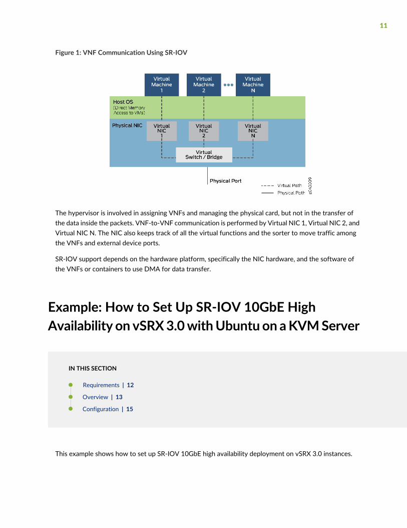
Figure 1: VNF Communication Using SR-IOV
The hypervisor is involved in assigning VNFs and managing the physical card, but not in the transfer ofthe data inside the packets. VNF-to-VNF communication is performed by Virtual NIC 1, Virtual NIC 2, andVirtual NIC N. The NIC also keeps track of all the virtual functions and the sorter to move traffic amongthe VNFs and external device ports.
SR-IOV support depends on the hardware platform, specifically the NIC hardware, and the software ofthe VNFs or containers to use DMA for data transfer.
Example: How to Set Up SR-IOV 10GbE HighAvailability on vSRX3.0withUbuntu on aKVMServer
IN THIS SECTION
Requirements | 12
Overview | 13
Configuration | 15
This example shows how to set up SR-IOV 10GbE high availability deployment on vSRX 3.0 instances.
11

Requirements
This example uses the following hardware, software components, and operating systems:
Device
• vSRX 3.0
Software
• Junos OS Release 20.4R1
Hardware
• NIC: Intel Corporation Ethernet Controller X710/X520/82599
• Driver: i40e version: 2.1.14-k or ixgbe version: 5.1.0-k
• CPU: Intel (R) Xeon (R) Gold 5120 CPU @ 2.20 GHz
• 56 CPUs
• 0- 55 online CPUs list
• 2 threads per core
• 14 cores per socket
• 2 sockets
• 2 non-uniform memory access (NUMA) nodes
Formore information onNICs, Hypervisors, and ports supportedwith SR-IOV seeHardware Specifications.
12

Operating System
Table 3: SR-IOV HA Supported KVM OS and Network Adapter Information
SupportKVM OS and Network Adapters
YesIntel 82599/X520/X540 (82599 ixgb driver based)
YesIntel X710/XL710/XXV710/X722 (i40e driver based)
NoMellanox ConnectX-4/ConnectX-4 Lx
YesUbuntu 18.04 (kernel:4.15.0 + libvirt:4.0.0) and 20.04 (kernel:5.4.0 + libvirt:6.0.0)LTS
YesRedhat 8.2 (kernel:4.18.0 + libvirt:4.5.0)
Operating Systems used in this example are:
• Ubuntu 18.04.3 LTS on a KVM server
• Kernel: 4.15.0-64-generic
• Kernel: 4.18.0-193.1.2.el8_2.x86_64
• redhat rhel 8.2
Overview
This example shows how to:
• Set up the 10-Gigabit high availability deployment
• Build VFs bus information on NIC interfaces and change the XML template
• Configure basic vSRX 3.0 instances
In a high availability environment, the control link and fabric data links are key communication channelsfor chassis cluster stability. Both links are part of the same Linux bridge. The host operating system (Ubuntu)shares the CPU allotted for the vSRX 3.0 control plane for routine tasks and with one of the vSRX 3.0 PFEdata plane threads for packet processing. This contention for resources coupledwith the lack of a dedicatedVLAN or NIC for the control link could contribute to heartbeat misses.
Furthermore, interrupt handling on the host can also impact the performance. When packets arrive at theNIC, a hardware interrupt indication and the CPU core that services the vSRX 3.0 control plane must stop
13

and service the interrupt. A large number of packets from theNIC can lead tomore hardware interruptionsand less CPU resources to service the vSRX 3.0 control plane.
To overcome the design constraints and the CPU resource contention, we recommend the followingchanges:
• Allot dedicated CPU to each vSRX 3.0 control plane, vSRX 3.0 data plane, and the host operating system.
• Allot required memory on the host.
• Leverage SR-IOV for fabric interface in a high availability deployment.
• Remove GRE for control link communication and use multicast in high availability deployments.
• Enable IRQ affinity to avoid the interrupts handled by the CPUs for vSRX 3.0 control plane and dataplane.
• Enlarge the physical NIC descriptor from 512 to 4096 bytes.
We recommend you configure all revenue ports of vSRX 3.0 as SR-IOV. Also, on KVM you can configureSR-IOV high availability on management port -fxp0/ control port- em0 / fabric port-ge-0/0/*.
NOTE: SR-IOV high availability Layer 2 function is not supported. Also, VMware and MellanoxNIC do not support SR-IOV high availability functionality.
Figure 2 on page 15 shows the topology used in this example.
14

Figure 2: High Availability Trust and Untrust Dual NIC Topology
Configuration
IN THIS SECTION
SR-IOV High Availability Deployment | 16
Build Bus Information of Virtual Functions on NICs | 18
Configure vSRX 3.0 | 26
Verification | 27
Results | 33
15
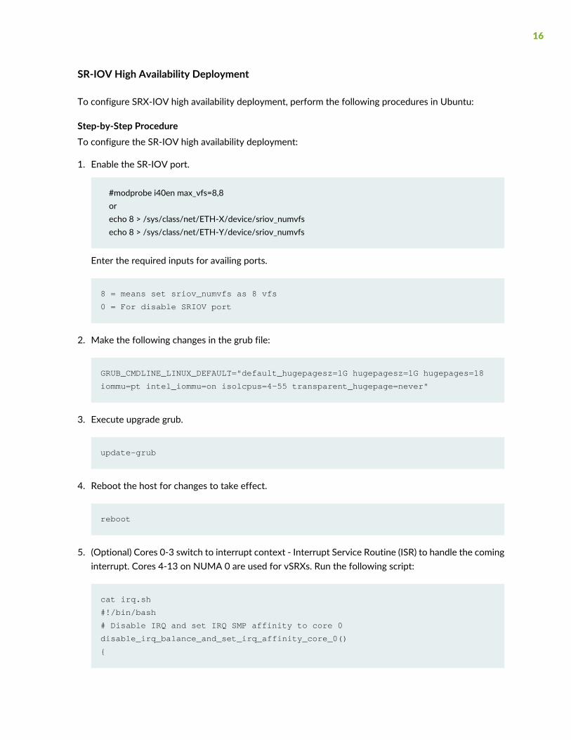
SR-IOV High Availability Deployment
To configure SRX-IOV high availability deployment, perform the following procedures in Ubuntu:
Step-by-Step ProcedureTo configure the SR-IOV high availability deployment:
1. Enable the SR-IOV port.
#modprobe i40en max_vfs=8,8orecho 8 > /sys/class/net/ETH-X/device/sriov_numvfsecho 8 > /sys/class/net/ETH-Y/device/sriov_numvfs
Enter the required inputs for availing ports.
8 = means set sriov_numvfs as 8 vfs
0 = For disable SRIOV port
2. Make the following changes in the grub file:
GRUB_CMDLINE_LINUX_DEFAULT="default_hugepagesz=1G hugepagesz=1G hugepages=18
iommu=pt intel_iommu=on isolcpus=4-55 transparent_hugepage=never"
3. Execute upgrade grub.
update-grub
4. Reboot the host for changes to take effect.
reboot
5. (Optional) Cores 0-3 switch to interrupt context - Interrupt Service Routine (ISR) to handle the cominginterrupt. Cores 4-13 on NUMA 0 are used for vSRXs. Run the following script:
cat irq.sh
#!/bin/bash
# Disable IRQ and set IRQ SMP affinity to core 0
disable_irq_balance_and_set_irq_affinity_core_0()
{
16

echo f > /proc/irq/default_smp_affinity
#Disable_IRQ_Balance
if [ -f /etc/init.d/irqbalance ]; then
/etc/init.d/irqbalance stop
fi
#set_irq_affinity_core_0
#for IRQ in `seq 0 512`;
for IRQDIR in `ls -d /proc/irq/*`;
do
if [ -d $IRQDIR ]; then
echo f > $IRQDIR/smp_affinity 2>/dev/null
cat $IRQDIR/smp_affinity
fi
done
}
6. Increase tx and rx buffer size to 4096 on all NICs.
ethtool -G <ethx> rx 4096
ethtool -G <ethx> tx 4096
7. Turn off flow control.
ethtool -A <ethx> autoneg off rx off tx off
8. Check for the server persistent after reboot.
cat /etc/rc.local
#!/bin/bash
echo 7 > /sys/class/net/eth0/device/sriov_numvfs
echo 7 > /sys/class/net/eth1/device/sriov_numvfs
echo 7 > /sys/class/net/eth2/device/sriov_numvfs
echo 7 > /sys/class/net/eth3/device/sriov_numvfs
/bin/irq.sh
9. Set SR-IOV VF trust mode on and spoof checking off.
# The Linux setting for SR-IOV VF Trust Mode: --ip link set dev [PF] vf [VF_index] trust off/on
17

# The setting for SR-IOV VF spoof checking: --ip link set dev [PF] vf [VF_index] spoof checking on/off
Or, you can also add below command to rc.local script:
nic=eth0;for i in $(seq 0 15);do ip link set $nic vf $i spoofchk off trust on
promisc on mtu 9000;done
nic=eth1;for i in $(seq 0 15);do ip link set $nic vf $i spoofchk off trust on
promisc on mtu 9000;done
nic=eth2;for i in $(seq 0 15);do ip link set $nic vf $i spoofchk off trust on
promisc on mtu 9000;done
nic=eth3;for i in $(seq 0 15);do ip link set $nic vf $i spoofchk off trust on
promisc on mtu 9000;done
Build Bus Information of Virtual Functions on NICs
Step-by-Step Procedure
18
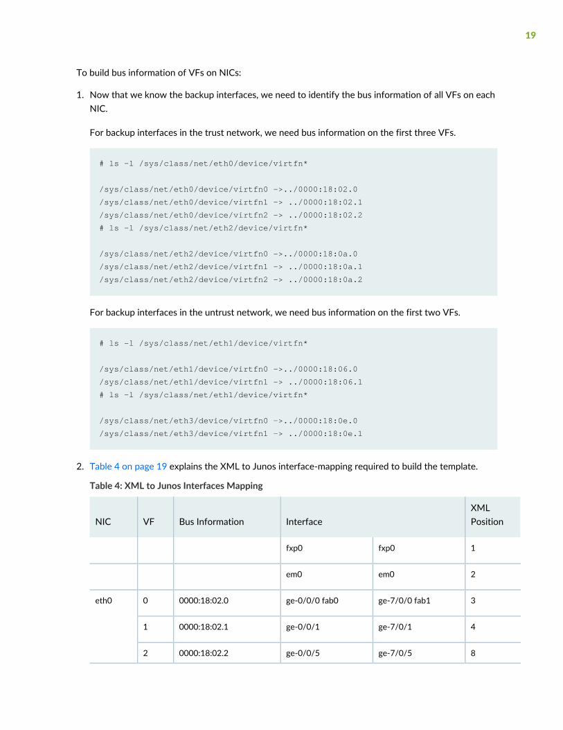
To build bus information of VFs on NICs:
1. Now that we know the backup interfaces, we need to identify the bus information of all VFs on eachNIC.
For backup interfaces in the trust network, we need bus information on the first three VFs.
# ls -l /sys/class/net/eth0/device/virtfn*
/sys/class/net/eth0/device/virtfn0 ->../0000:18:02.0
/sys/class/net/eth0/device/virtfn1 -> ../0000:18:02.1
/sys/class/net/eth0/device/virtfn2 -> ../0000:18:02.2
# ls -l /sys/class/net/eth2/device/virtfn*
/sys/class/net/eth2/device/virtfn0 ->../0000:18:0a.0
/sys/class/net/eth2/device/virtfn1 -> ../0000:18:0a.1
/sys/class/net/eth2/device/virtfn2 -> ../0000:18:0a.2
For backup interfaces in the untrust network, we need bus information on the first two VFs.
# ls -l /sys/class/net/eth1/device/virtfn*
/sys/class/net/eth1/device/virtfn0 ->../0000:18:06.0
/sys/class/net/eth1/device/virtfn1 -> ../0000:18:06.1
# ls -l /sys/class/net/eth1/device/virtfn*
/sys/class/net/eth3/device/virtfn0 ->../0000:18:0e.0
/sys/class/net/eth3/device/virtfn1 -> ../0000:18:0e.1
2. Table 4 on page 19 explains the XML to Junos interface-mapping required to build the template.
Table 4: XML to Junos Interfaces Mapping
XMLPositionInterfaceBus InformationVFNIC
1fxp0fxp0
2em0em0
3ge-7/0/0 fab1ge-0/0/0 fab00000:18:02.00eth0
4ge-7/0/1ge-0/0/10000:18:02.11
8ge-7/0/5ge-0/0/50000:18:02.22
19

Table 4: XML to Junos Interfaces Mapping (continued)
XMLPositionInterfaceBus InformationVFNIC
6ge-7/0/3ge-0/0/30000:18:06.00eth1
5ge-7/0/2ge-0/0/20000:18:0a.00eth2
7ge-7/0/4ge-0/0/40000:18:0e.00eth3
The XML to Junos configuration is sequential. The first interface is assigned to fxp0 , second interfaceis assigned to em0 and the last interface is assigned to ge-0/0/9 as shown in Table 5 on page 20.
3. Develop the following Table 5 on page 20 based on Table 4 on page 19 in step 3.
Table 5: Junos Interfaces and Bus Information
Junos interfacesBUS InformationXML Position
fxp0BR01
em0BR12
ge-0/0/00000:18:02.03
ge-0/0/10000:18:02.14
ge-0/0/20000:18:0a.05
ge-0/0/30000:18:06.06
ge-0/0/40000:18:0e.07
ge-0/0/50000:18:02.28
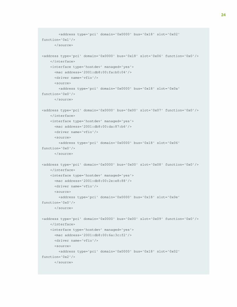
4. Modify the interface stanza 2,3,4,8 and 12 in XML template below as per the table in step 4.
<domain type='kvm'>
<name>vm-name</name>
<uuid>f5679184-a066-446b-a812-4fda2e9278dd</uuid>
<memory unit='KiB'>8388608</memory>
20

<currentMemory unit='KiB'>8388608</currentMemory>
<memoryBacking>
<hugepages/>
<locked/>
</memoryBacking>
<vcpu placement='static' cpuset='4-9'>6</vcpu>
<cputune>
<vcpupin vcpu='0' cpuset='4'/>
<vcpupin vcpu='1' cpuset='5'/>
<vcpupin vcpu='2' cpuset='6'/>
<vcpupin vcpu='3' cpuset='7'/>
<vcpupin vcpu='4' cpuset='8'/>
<vcpupin vcpu='5' cpuset='9'/>
</cputune>
<numatune>
<memory mode='strict' nodeset='0'/>
</numatune>
<resource>
<partition>/machine</partition>
</resource>
<os>
<type arch='x86_64' machine='pc-i440fx-xenial'>hvm</type>
<boot dev='hd'/>
</os>
<features>
<acpi/>
<apic/>
</features>
<cpu mode='host-passthrough' check='none'>
<feature policy='require' name='pbe'/>
<feature policy='require' name='tm2'/>
<feature policy='require' name='est'/>
<feature policy='require' name='vmx'/>
<feature policy='require' name='aes'/>
<feature policy='require' name='osxsave'/>
<feature policy='require' name='smx'/>
<feature policy='require' name='ss'/>
<feature policy='require' name='ds'/>
<feature policy='require' name='vme'/>
<feature policy='require' name='dtes64'/>
<feature policy='require' name='monitor'/>
<feature policy='require' name='ht'/>
<feature policy='force' name='dca'/>
<feature policy='require' name='pcid'/>
21

<feature policy='require' name='tm'/>
<feature policy='require' name='pdcm'/>
<feature policy='require' name='pdpe1gb'/>
<feature policy='require' name='ds_cpl'/>
<feature policy='require' name='xtpr'/>
<feature policy='require' name='acpi'/>
<feature policy='disable' name='invtsc'/>
</cpu>
<clock offset='utc'>
<timer name='rtc' tickpolicy='catchup'/>
<timer name='pit' tickpolicy='delay'/>
<timer name='hpet' present='no'/>
</clock>
<on_poweroff>destroy</on_poweroff>
<on_reboot>restart</on_reboot>
<on_crash>restart</on_crash>
<pm>
<suspend-to-mem enabled='no'/>
<suspend-to-disk enabled='no'/>
</pm>
<devices>
<emulator>/usr/bin/kvm-spice</emulator>
<disk type='file' device='disk'>
<driver name='qemu' type='qcow2'/>
<source file='/var/lib/libvirt/images/sriovvsrx/vSRX_Image.qcow2'/>
<target dev='hda' bus='ide'/>
<address type='drive' controller='0' bus='0' target='0' unit='0'/>
</disk>
<controller type='usb' index='0' model='ich9-ehci1'>
<address type='pci' domain='0x0000' bus='0x00' slot='0x0c' function='0x7'/>
</controller>
<controller type='usb' index='0' model='ich9-uhci1'>
<master startport='0'/>
<address type='pci' domain='0x0000' bus='0x00' slot='0x0c' function='0x0'
multifunction='on'/>
</controller>
<controller type='usb' index='0' model='ich9-uhci2'>
<master startport='2'/>
<address type='pci' domain='0x0000' bus='0x00' slot='0x0c' function='0x1'/>
</controller>
<controller type='usb' index='0' model='ich9-uhci3'>
<master startport='4'/>
22

<address type='pci' domain='0x0000' bus='0x00' slot='0x0c' function='0x2'/>
</controller>
<controller type='pci' index='0' model='pci-root'/>
<controller type='ide' index='0'>
<address type='pci' domain='0x0000' bus='0x00' slot='0x01' function='0x1'/>
</controller>
<controller type='virtio-serial' index='0'>
<address type='pci' domain='0x0000' bus='0x00' slot='0x0b' function='0x0'/>
</controller>
<interface type='bridge'>
<mac address='2001:db8:00:46:05:b6'/>
<source bridge='br0'/>
<model type='virtio'/>
<mtu size='9100'/>
<address type='pci' domain='0x0000' bus='0x00' slot='0x03' function='0x0'/>
<driver queues='8'/> # delete from existing templates
</interface>
<interface type='bridge'>
<mac address='2001:db8:00:5e:c9:06'/>
<source bridge='br1'/>
<model type='virtio'/>
<mtu size='9100'/>
<address type='pci' domain='0x0000' bus='0x00' slot='0x04' function='0x0'/>
</interface>
<interface type='hostdev' managed='yes'>
<mac address='2001:db8:00:4e:f6:89'/>
<driver name='vfio'/>
<source>
<address type='pci' domain='0x0000' bus='0x18' slot='0x02'
function='0x0'/>
</source>
<vlan>
<tag id='3681'/>
</vlan>
<address type='pci' domain='0x0000' bus='0x00' slot='0x05' function='0x0'/>
</interface>
<interface type='hostdev' managed='yes'>
<mac address='2001:db8:00:4e:f5:f9'/>
<driver name='vfio'/>
<source>
23
<address type='pci' domain='0x0000' bus='0x18' slot='0x02'
function='0x1'/>
</source>
<address type='pci' domain='0x0000' bus='0x18' slot='0x06' function='0x0'/>
</interface>
<interface type='hostdev' managed='yes'>
<mac address='2001:db8:00:fa:b0:04'/>
<driver name='vfio'/>
<source>
<address type='pci' domain='0x0000' bus='0x18' slot='0x0a'
function='0x0'/>
</source>
<address type='pci' domain='0x0000' bus='0x00' slot='0x07' function='0x0'/>
</interface>
<interface type='hostdev' managed='yes'>
<mac address='2001:db8:00:da:87:b6'/>
<driver name='vfio'/>
<source>
<address type='pci' domain='0x0000' bus='0x18' slot='0x06'
function='0x0'/>
</source>
<address type='pci' domain='0x0000' bus='0x00' slot='0x08' function='0x0'/>
</interface>
<interface type='hostdev' managed='yes'>
<mac address='2001:db8:00:2e:e8:88'/>
<driver name='vfio'/>
<source>
<address type='pci' domain='0x0000' bus='0x18' slot='0x0e'
function='0x0'/>
</source>
<address type='pci' domain='0x0000' bus='0x00' slot='0x09' function='0x0'/>
</interface>
<interface type='hostdev' managed='yes'>
<mac address='2001:db8:00:6a:3c:f2'/>
<driver name='vfio'/>
<source>
<address type='pci' domain='0x0000' bus='0x18' slot='0x02'
function='0x2'/>
</source>
24

<address type='pci' domain='0x0000' bus='0x00' slot='0x0a' function='0x0'/>
<serial type='tcp'>
<source mode='bind' host='192.0.2.1' service='8636' tls='no'/>
<protocol type='telnet'/>
<target type='isa-serial' port='0'>
<model name='isa-serial'/>
</target>
</serial>
<console type='tcp'>
<source mode='bind' host='192.0.2.1' service='8636' tls='no'/>
<protocol type='telnet'/>
<target type='serial' port='0'/>
</console>
<channel type='spicevmc'>
<target type='virtio' name='com.redhat.spice.0'/>
<address type='virtio-serial' controller='0' bus='0' port='1'/>
</channel>
<input type='mouse' bus='ps2'/>
<input type='keyboard' bus='ps2'/>
<graphics type='spice' autoport='yes' listen='192.0.2.1'>
<listen type='address' address='192.0.2.1'/>
<image compression='off'/>
</graphics>
<sound model='ich6'>
<address type='pci' domain='0x0000' bus='0x00' slot='0x0a' function='0x0'/>
</sound>
<video>
<model type='qxl' ram='65536' vram='65536' vgamem='16384' heads='1'
primary='yes'/>
<address type='pci' domain='0x0000' bus='0x00' slot='0x02' function='0x0'/>
</video>
<redirdev bus='usb' type='spicevmc'>
<address type='usb' bus='0' port='1'/>
</redirdev>
<redirdev bus='usb' type='spicevmc'>
<address type='usb' bus='0' port='2'/>
</redirdev>
<memballoon model='virtio'>
<address type='pci' domain='0x0000' bus='0x00' slot='0x0d' function='0x0'/>
</memballoon>
</devices>
25

<seclabel type='dynamic' model='apparmor' relabel='yes'/>
<seclabel type='dynamic' model='dac' relabel='yes'/>
</domain>
Configure vSRX 3.0
CLI Quick ConfigurationTo quickly configure this example, copy the following commands, paste them into a text file, remove anyline breaks, change any details necessary to match your network configuration, copy and paste thecommands into the CLI at the [edit] hierarchy level, and then enter commit from configuration mode.
NOTE: ge-0/0/3, ge-0/0/4, ge-7/0/3, ge-7/0/4 are not used in this configuration.
set groups node0 system host-name host-name-node0set groups node0 system backup-router 198.51.100.254set groups node0 system backup-router destination 0.0.0.0/0set groups node0 interfaces fxp0 unit 0 family inet address 198.51.100.248/20set groups node1 system host-name host-name-node1set groups node1 system backup-router 198.51.100.254set groups node1 system backup-router destination 0.0.0.0/0set groups node1 interfaces fxp0 unit 0 family inet address 198.51.100.249/20set apply-groups "${node}"set chassis cluster reth-count 2set chassis cluster redundancy-group 0 node 0 priority 100set chassis cluster redundancy-group 0 node 1 priority 1set chassis cluster redundancy-group 1 node 0 priority 100set chassis cluster redundancy-group 1 node 1 priority 1set chassis cluster redundancy-group 2 node 0 priority 100set chassis cluster redundancy-group 2 node 1 priority 1set interfaces ge-0/0/1 gigether-options redundant-parent reth0set interfaces ge-0/0/2 gigether-options redundant-parent reth1set interfaces ge-7/0/1 gigether-options redundant-parent reth0set interfaces ge-7/0/2 gigether-options redundant-parent reth1set interfaces fab0 fabric-options member-interfaces ge-0/0/0set interfaces fab1 fabric-options member-interfaces ge-7/0/0set interfaces fab0 fabric-options member-interfaces ge-0/0/5set interfaces fab1 fabric-options member-interfaces ge-7/0/5set interfaces reth0 redundant-ether-options redundancy-group 1set interfaces reth0 unit 0 family inet address 192.168.10.1/24
26

set interfaces reth1 redundant-ether-options redundancy-group 2set interfaces reth1 unit 0 family inet address 192.168.11.1/24set interfaces reth0 vlan-taggingset interfaces reth0 unit 0 vlan-id 3601set interfaces reth1 vlan-taggingset interfaces reth1 unit 0 vlan-id 3602set security zones security-zone TRUST host-inbound-traffic system-services allset security zones security-zone TRUST host-inbound-traffic protocols allset security zones security-zone TRUST interfaces reth0.0set security zones security-zone UNTRUST host-inbound-traffic system-services allset security zones security-zone UNTRUST host-inbound-traffic protocols allset security zones security-zone UNTRUST interfaces reth1.0
Verification
IN THIS SECTION
Verifying Chassis Cluster Status | 27
Confirm that the configuration is working properly.
Verifying Chassis Cluster Status
PurposeVerify the chassis cluster status, statistics, and redundancy group information.
ActionFrom operational mode, enter the following commands.
{primary:node0}
user@host> show chassis cluster interfaces
Control link status: Up
Control interfaces:
Index Interface Monitored-Status Internal-SA Security
0 em0 Up Disabled Disabled
27

Fabric link status: Up
Fabric interfaces:
Name Child-interface Status Security
(Physical/Monitored)
fab0 ge-0/0/0 Up / Up Disabled
fab0 ge-0/0/5 Up / Up Disabled
fab1 ge-7/0/0 Up / Up Disabled
fab1 ge-7/0/5 Up / Up Disabled
Redundant-ethernet Information:
Name Status Redundancy-group
reth0 Down Not configured
reth1 Up 1
reth2 Up 2
Redundant-pseudo-interface Information:
Name Status Redundancy-group
lo0 Up 0
{primary:node0}
user@host> show chassis cluster statistics
Control link statistics:
Control link 0:
Heartbeat packets sent: 1797825
Heartbeat packets received: 1797280
Heartbeat packet errors: 0
Fabric link statistics:
Child link 0
Probes sent: 1329328
Probes received: 1328840
Child link 1
Probes sent: 0
Probes received: 0
Services Synchronized:
Service name RTOs sent RTOs received
Translation context 0 0
Incoming NAT 0 0
Resource manager 0 0
DS-LITE create 0 0
28

Session create 0 0
IPv6 session create 0 0
Session close 0 0
IPv6 session close 0 0
Session change 0 0
IPv6 session change 0 0
ALG Support Library 0 0
Gate create 0 0
Session ageout refresh requests 0 0
IPv6 session ageout refresh requests 0 0
Session ageout refresh replies 0 0
IPv6 session ageout refresh replies 0 0
IPSec VPN 0 0
Firewall user authentication 0 0
MGCP ALG 0 0
H323 ALG 0 0
SIP ALG 0 0
SCCP ALG 0 0
PPTP ALG 0 0
JSF PPTP ALG 0 0
RPC ALG 0 0
RTSP ALG 0 0
RAS ALG 0 0
MAC address learning 0 0
GPRS GTP 0 0
GPRS SCTP 0 0
GPRS FRAMEWORK 0 0
JSF RTSP ALG 0 0
JSF SUNRPC MAP 0 0
JSF MSRPC MAP 0 0
DS-LITE delete 0 0
JSF SLB 0 0
APPID 0 0
JSF MGCP MAP 0 0
JSF H323 ALG 0 0
JSF RAS ALG 0 0
JSF SCCP MAP 0 0
JSF SIP MAP 0 0
PST_NAT_CREATE 0 0
PST_NAT_CLOSE 0 0
PST_NAT_UPDATE 0 0
29
JSF TCP STACK 0 0
JSF IKE ALG 0 0
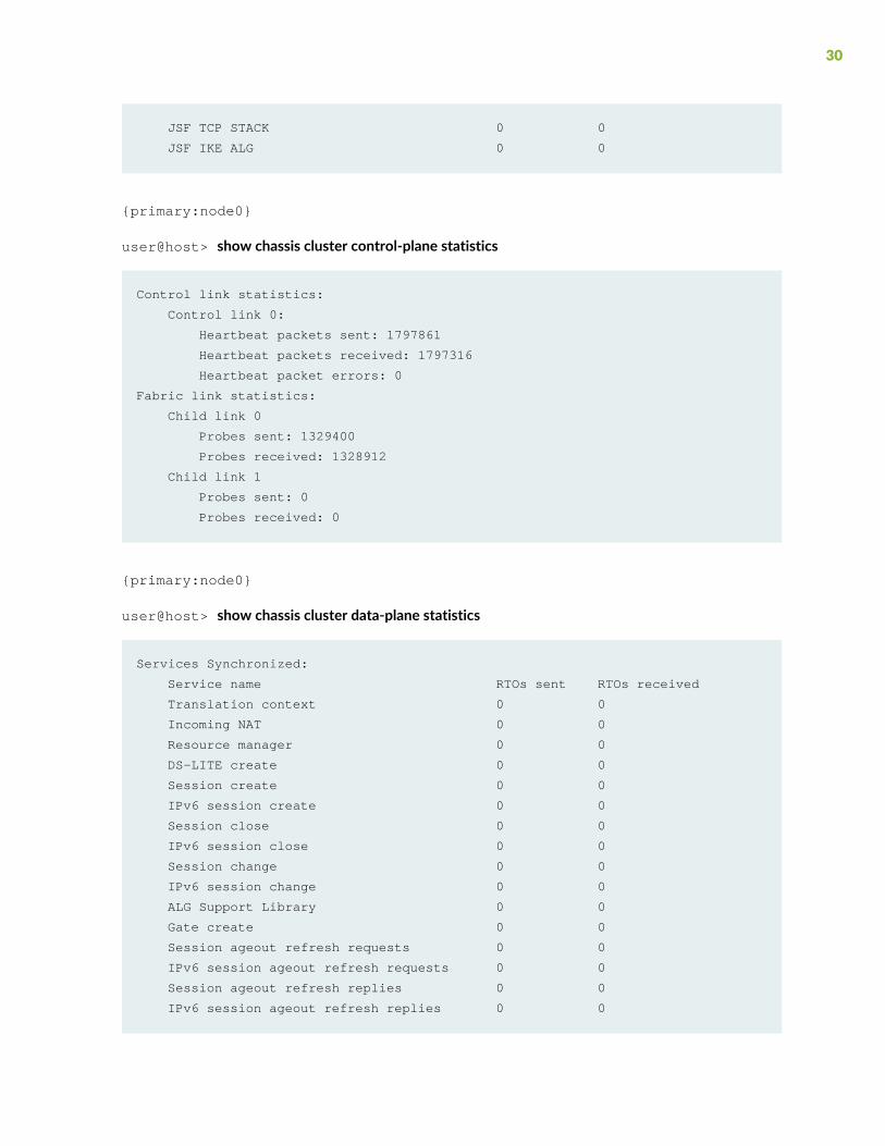
{primary:node0}
user@host> show chassis cluster control-plane statistics
Control link statistics:
Control link 0:
Heartbeat packets sent: 1797861
Heartbeat packets received: 1797316
Heartbeat packet errors: 0
Fabric link statistics:
Child link 0
Probes sent: 1329400
Probes received: 1328912
Child link 1
Probes sent: 0
Probes received: 0
{primary:node0}
user@host> show chassis cluster data-plane statistics
Services Synchronized:
Service name RTOs sent RTOs received
Translation context 0 0
Incoming NAT 0 0
Resource manager 0 0
DS-LITE create 0 0
Session create 0 0
IPv6 session create 0 0
Session close 0 0
IPv6 session close 0 0
Session change 0 0
IPv6 session change 0 0
ALG Support Library 0 0
Gate create 0 0
Session ageout refresh requests 0 0
IPv6 session ageout refresh requests 0 0
Session ageout refresh replies 0 0
IPv6 session ageout refresh replies 0 0
30

IPSec VPN 0 0
Firewall user authentication 0 0
MGCP ALG 0 0
H323 ALG 0 0
SIP ALG 0 0
SCCP ALG 0 0
PPTP ALG 0 0
JSF PPTP ALG 0 0
RPC ALG 0 0
RTSP ALG 0 0
RAS ALG 0 0
MAC address learning 0 0
GPRS GTP 0 0
GPRS SCTP 0 0
GPRS FRAMEWORK 0 0
JSF RTSP ALG 0 0
JSF SUNRPC MAP 0 0
JSF MSRPC MAP 0 0
DS-LITE delete 0 0
JSF SLB 0 0
APPID 0 0
JSF MGCP MAP 0 0
JSF H323 ALG 0 0
JSF RAS ALG 0 0
JSF SCCP MAP 0 0
JSF SIP MAP 0 0
PST_NAT_CREATE 0 0
PST_NAT_CLOSE 0 0
PST_NAT_UPDATE 0 0
JSF TCP STACK 0 0
JSF IKE ALG 0 0
{primary:node0}
user@host> show chassis cluster status redundancy-group 1
Monitor Failure codes:
CS Cold Sync monitoring FL Fabric Connection monitoring
GR GRES monitoring HW Hardware monitoring
IF Interface monitoring IP IP monitoring
LB Loopback monitoring MB Mbuf monitoring
NH Nexthop monitoring NP NPC monitoring
31

SP SPU monitoring SM Schedule monitoring
CF Config Sync monitoring RE Relinquish monitoring
IS IRQ storm
Cluster ID: 1
Node Priority Status Preempt Manual Monitor-failures
Redundancy group: 1 , Failover count: 1
node0 200 primary no no None
node1 1 secondary no no None
Verification of deployment results
[user@host-kvm126 libvirt]# virsh domiflist vm-name
Interface Type Source Model MAC
-------------------------------------------------------
vnet0 bridge bro virtio 52:54:00:a5:6a:59
vnet1 bridge br1 virtio 52:54:00:34:03:53
- hostdev - - 52:54:00:ef:43:b6
- hostdev - - 52:54:00:83:5f:e2
- hostdev - - 52:54:00:99:85:ac
- hostdev - - 52:54:00:f5:6b:30
- hostdev - - 52:54:00:67:83:5f
- hostdev - - 52:54:00:78:db:79
[user@host-kvm126 libvirt]# ip -d link show dev p2p2 |grep "vf 1 "
vf 1 link/ether 52:54:00:ef:43:b6 brd ff:ff:ff:ff:ff:ff, vlan 3681, spoof
checking off, link-state auto, trust on
[root@cnrd-kvm126 libvirt]# ip -d link show dev p2p3 |grep "vf 2 "
vf 2 link/ether 52:54:00:83:5f:e2 brd ff:ff:ff:ff:ff:ff, spoof checking
off, link-state auto, trust on
[root@cnrd-kvm126 libvirt]# ip -d link show dev p2p3 |grep "vf 3 "
vf 3 link/ether 52:54:00:99:85:ac brd ff:ff:ff:ff:ff:ff, spoof checking
off, link-state auto, trust on
[root@cnrd-kvm126 libvirt]#
MeaningThe sample output shows that there are no manual failover in chassis cluster status and provides you thespoof checking status and SR-IOV VF trust mode state.
32
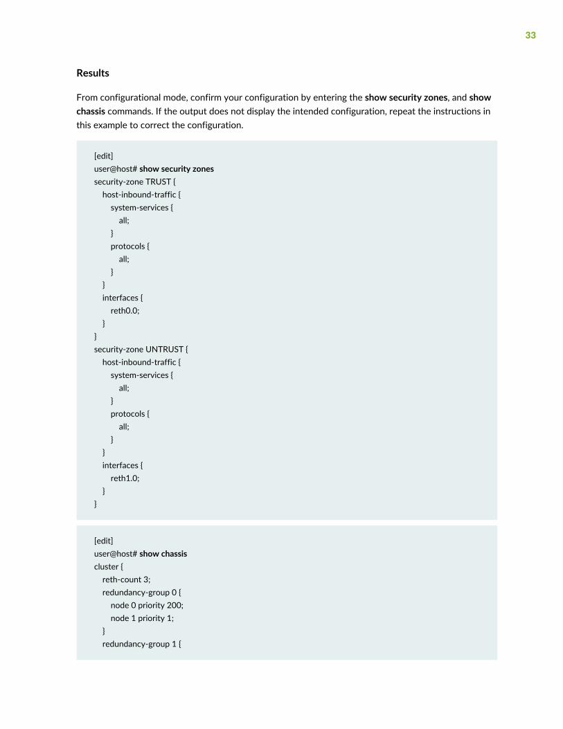
Results
From configurational mode, confirm your configuration by entering the show security zones, and showchassis commands. If the output does not display the intended configuration, repeat the instructions inthis example to correct the configuration.
[edit]user@host# show security zonessecurity-zone TRUST {host-inbound-traffic {system-services {all;
}protocols {all;
}}interfaces {reth0.0;
}}security-zone UNTRUST {host-inbound-traffic {system-services {all;
}protocols {all;
}}interfaces {reth1.0;
}}
[edit]user@host# show chassiscluster {reth-count 3;redundancy-group 0 {node 0 priority 200;node 1 priority 1;
}redundancy-group 1 {
33

node 0 priority 200;node 1 priority 1;
}redundancy-group 2 {node 0 priority 200;node 1 priority 1;
}}
34
Related Documents


