1 CONFIGURING SIEMENS PCS7 TO USE PLCSIM

Welcome message from author
This document is posted to help you gain knowledge. Please leave a comment to let me know what you think about it! Share it to your friends and learn new things together.
Transcript
1
CONFIGURING SIEMENS PCS7
TO USE PLCSIM
TABLE OF CONTENTS
CONFIGURING SIEMENS PCS7
TO USE PLCSIM
CONFIGURING SIEMENS PCS7
TO USE PLCSIM
1.0 PURPOSE ........................................................................................................ 3
2.0 SCOPE ............................................................................................................ 3
3.0 REFERENCES .................................................................................................. 3
4.0 DEFINITIONS/ACRONYMS ................................................................................. 3
5.0 DETERMINING SYSTEM ARCHITECTURE ............................................................ 4
5.1 OVERVIEW ................................................................................................... 4
5.2 SINGLE STATION .......................................................................................... 4
5.3 MULTI-STATION ............................................................................................ 5
6.0 COMMUNICATION METHOD ............................................................................... 5
6.1 HOW TO DETERMINE YOUR METHOD ............................................................. 7
6.1.1 Determining TCP/IP or ISO .................................................................. 7
6.1.2 AS Station Configuration Design (TCP/IP only) ....................................... 8
6.1.3 AS Station Configuration Design (TCP/IP, ISO, or Both) ........................... 9
6.1.4 OS and ES Station Configuration Design................................................ 9
7.0 PROJECT CONFIGURATION ............................................................................. 10
7.1 MPI ................................................................................................ 10
7.1.1 Configure Your Project ...................................................................... 10
7.2 TCP/IP OR ISO ............................................................................................ 17
7.2.1 Configure Your Project ...................................................................... 17
3
1.0 PURPOSE
The purpose of this document is to guide one through different configuration strategies and
possibilities with Siemens Simatic PCS7 simulation with the use of Siemens S7-PLCSIM.
2.0 SCOPE
This document only applies to Siemens Simatic PCS7 and Siemens S7-PLCSIM. In addition, this
document only supports PCS7 projects that are configured by Siemens Best Practice guidelines.
3.0 REFERENCES
• S7-PLCSIM – Testing Your S7-CPU Programs – manual
• SIMATIC Process Control System PCS 7 Compendium Part A – Configuration Guidelines
• PCS 7 – Configuration Manual Engineering System
• PCS 7 – Configuration Manual Operator Station
4.0 DEFINITIONS/ACRONYMS
AS – Automation Station (DCS CPU)
CS – Distributed Control System
ES – Engineering Station
IO – Inputs and Outputs
ISO – Industrial Ethernet Siemens Standard (MAC/Hardware address)
MPI – Message Passing Interface
Multiproject – A true use of a multiproject by Siemens PCS7 Best Practices. By default, the
PCS7 project creation wizard does not initially set the project up in this manner.
OS – Operator Station
PC – Personal Computer
PCS7 – Reference to Siemens Simatic PCS7 (versions 6.0 and up)
PLCSIM – Reference to Siemens S7-PLCSIM simulator software only
TCP/IP – Transmission Control Protocol / Internet Protocol
S7Program – Siemens Step 7 Program within the AS
4
5.0 DETERMINING
SYSTEM ARCHITECTURE
5.1 OVERVIEW
PLCSIM allows the Automation Station (AS) portion of your architecture to be represented
through software in order to test it without the physical need of the CPU and/or IO. Your
simulation station will always be an Engineering Station (ES). The system architecture is the
first step in determining how to configure the PCS7 project or multiproject for usage with
PLCSIM. Even though the project may change during the design stages, the same basic con-
cepts remain as the following two architectures are described. As already mentioned, the
other pieces of hardware (shown in the following examples) are not physically needed for
simulation purposes; however, they are crucial for proper configuration within your project.
5.2 SINGLE STATION
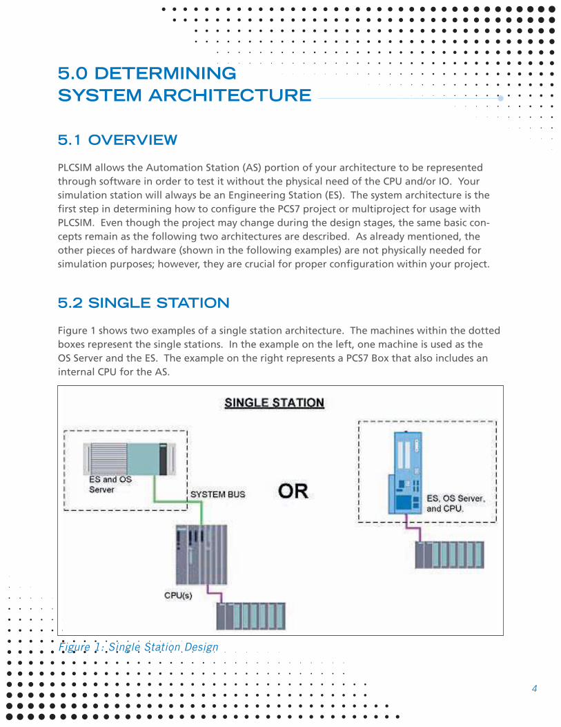
Figure 1 shows two examples of a single station architecture. The machines within the dotted
boxes represent the single stations. In the example on the left, one machine is used as the
OS Server and the ES. The example on the right represents a PCS7 Box that also includes an
internal CPU for the AS.
Figure 1: Single Station Design
5
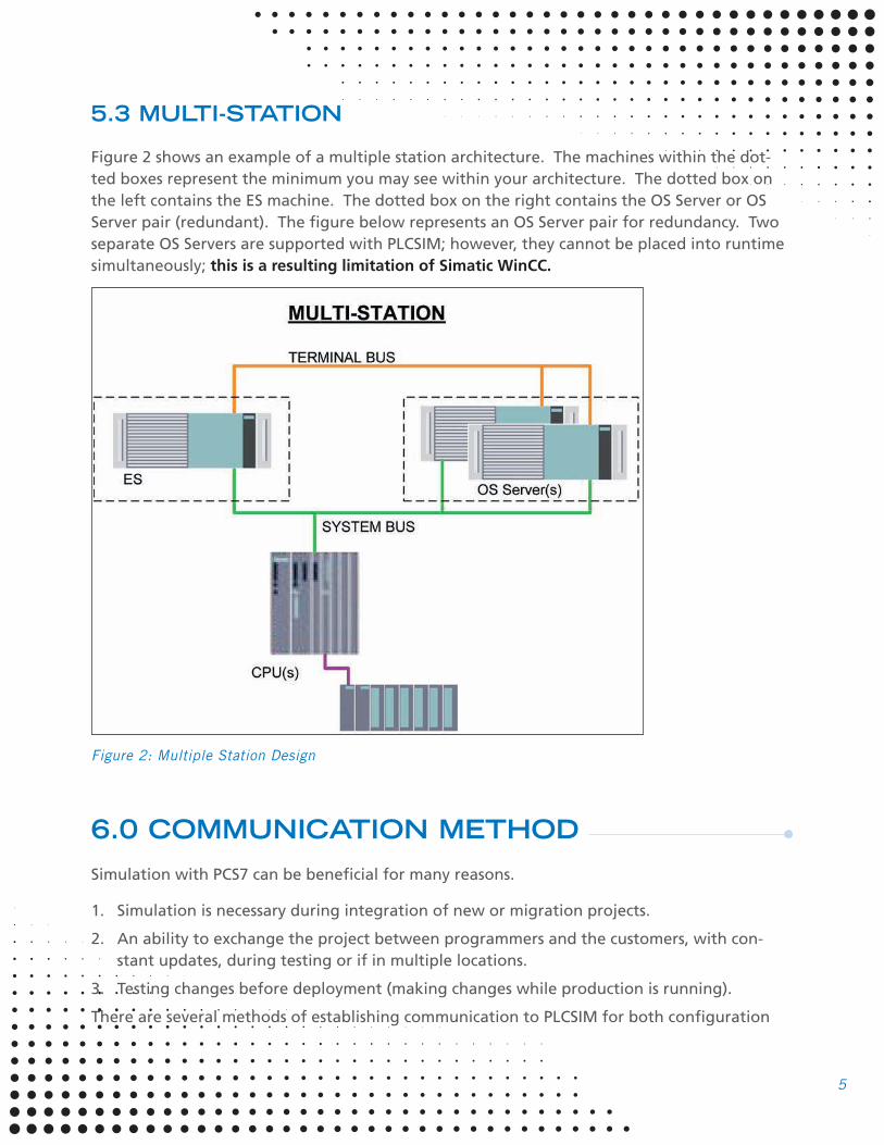
5.3 MULTI-STATION
Figure 2 shows an example of a multiple station architecture. The machines within the dot-
ted boxes represent the minimum you may see within your architecture. The dotted box on
the left contains the ES machine. The dotted box on the right contains the OS Server or OS
Server pair (redundant). The figure below represents an OS Server pair for redundancy. Two
separate OS Servers are supported with PLCSIM; however, they cannot be placed into runtime
simultaneously; this is a resulting limitation of Simatic WinCC.
Figure 2: Multiple Station Design
6.0 COMMUNICATION METHOD
Simulation with PCS7 can be beneficial for many reasons.
1. Simulation is necessary during integration of new or migration projects.
2. An ability to exchange the project between programmers and the customers, with con-
stant updates, during testing or if in multiple locations.
3. Testing changes before deployment (making changes while production is running).
There are several methods of establishing communication to PLCSIM for both configuration
6
and OS simulation; however, in this document we will be discussing the three most common
methods: MPI, TCP/IP, and ISO. All three methods are supported by the PCS7 OS (WinCC) and
have very similar configuration requirements.
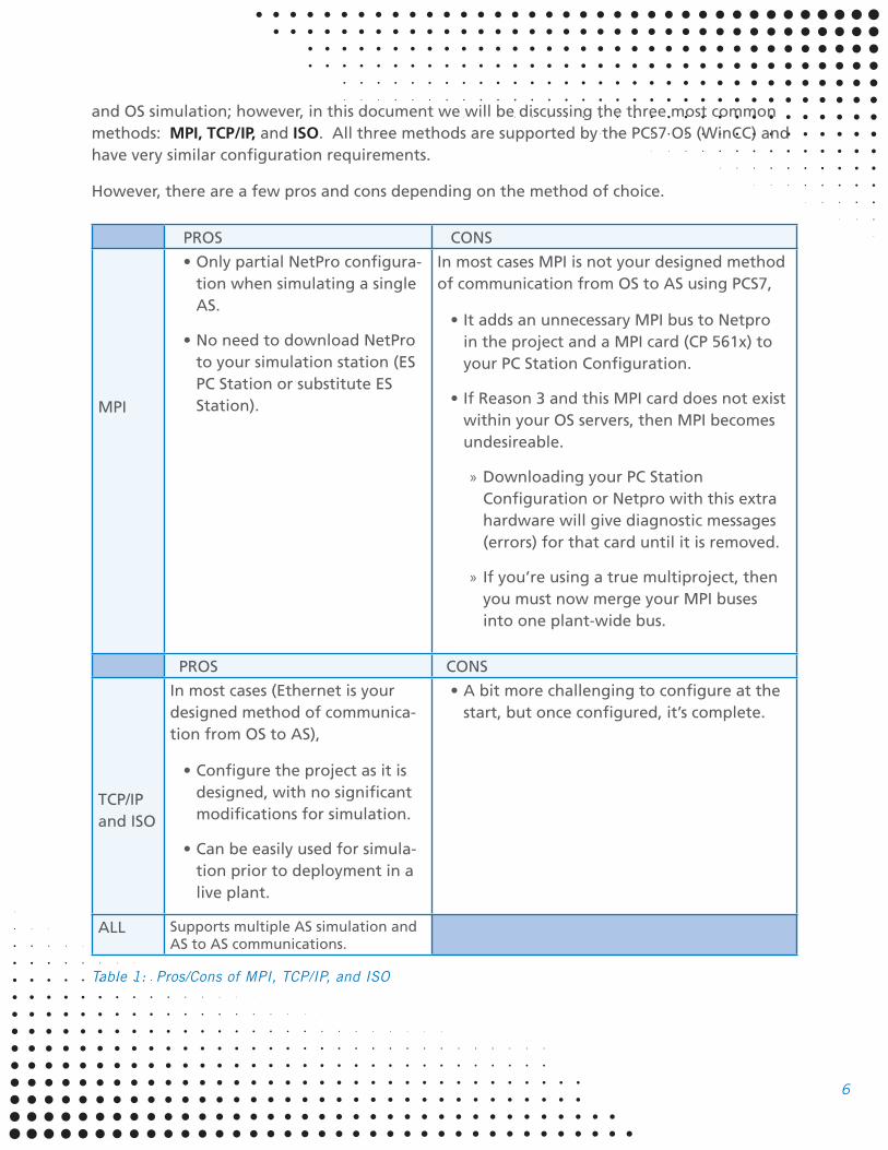
However, there are a few pros and cons depending on the method of choice.
PROS CONS
MPI
• Only partial NetPro configura-
tion when simulating a single
AS.
• No need to download NetPro
to your simulation station (ES
PC Station or substitute ES
Station).
In most cases MPI is not your designed method
of communication from OS to AS using PCS7,
• It adds an unnecessary MPI bus to Netpro
in the project and a MPI card (CP 561x) to
your PC Station Configuration.
• If Reason 3 and this MPI card does not exist
within your OS servers, then MPI becomes
undesireable.
» Downloading your PC Station
Configuration or Netpro with this extra
hardware will give diagnostic messages
(errors) for that card until it is removed.
» If you’re using a true multiproject, then
you must now merge your MPI buses
into one plant-wide bus.
PROS CONS
TCP/IP
and ISO
In most cases (Ethernet is your
designed method of communica-
tion from OS to AS),
• Configure the project as it is
designed, with no significant
modifications for simulation.
• Can be easily used for simula-
tion prior to deployment in a
live plant.
• A bit more challenging to configure at the
start, but once configured, it’s complete.
ALL Supports multiple AS simulation and AS to AS communications.
Table 1: Pros/Cons of MPI, TCP/IP, and ISO
7
6.1 HOW TO DETERMINE YOUR METHOD
MPI is a quick and easy method to use if you are temporarily setting up a project for testing
a single AS station. Otherwise, either ISO or TCP/IP methods can be used for simulation. TCP/
IP and ISO protocols are very similar when configuring PCS7 for communication. The method
will sometimes be required depending on hardware or station configuration design (see
Sections 6.1.2 – 6.1.4).
Within PCS7, MPI is not a realistic design for communications and is not recommended by
Siemens. However, for simulation purposes, it is supported and can be used. If this is your
method of choice, please go to Section 7.1.
If TCP/IP or ISO is determined to be your method of choice, please go to Section 7.2.
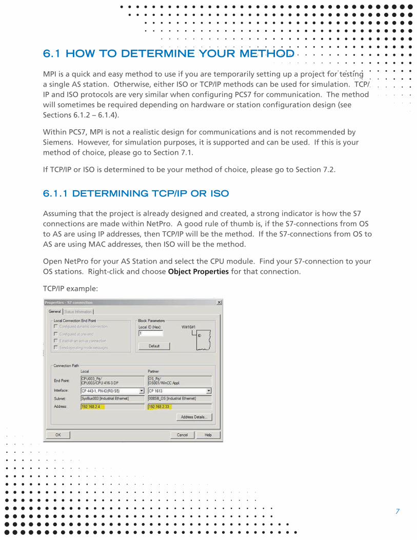
6.1.1 DETERMINING TCP/IP OR ISO
Assuming that the project is already designed and created, a strong indicator is how the S7
connections are made within NetPro. A good rule of thumb is, if the S7-connections from OS
to AS are using IP addresses, then TCP/IP will be the method. If the S7-connections from OS to
AS are using MAC addresses, then ISO will be the method.
Open NetPro for your AS Station and select the CPU module. Find your S7-connection to your
OS stations. Right-click and choose Object Properties for that connection.
TCP/IP example:

8
ISO example:
6.1.2 AS STATION CONFIGURATION DESIGN (TCP/IP ONLY)
Some AS stations only give you the option of configuring an IP address. Shown below is an
example: CPU 416-5 H PN/DP. If this is your case, then your method will be exclusively TCP/IP.
9
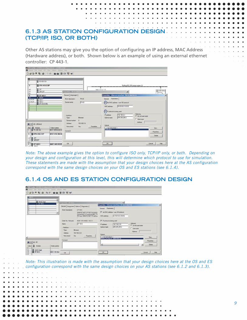
6.1.3 AS STATION CONFIGURATION DESIGN
(TCP/IP, ISO, OR BOTH)
Other AS stations may give you the option of configuring an IP address, MAC Address
(Hardware address), or both. Shown below is an example of using an external ethernet
controller: CP 443-1.
Note: The above example gives the option to configure ISO only, TCP/IP only, or both. Depending on
your design and configuration at this level, this will determine which protocol to use for simulation.
These statements are made with the assumption that your design choices here at the AS configuration
correspond with the same design choices on your OS and ES stations (see 6.1.4).
6.1.4 OS AND ES STATION CONFIGURATION DESIGN
Note: This illustration is made with the assumption that your design choices here at the OS and ES
configuration correspond with the same design choices on your AS stations (see 6.1.2 and 6.1.3).
10
7.0 PROJECT CONFIGURATION
The project configuration changes slightly depending on whether or not you have a single
station or multi-station design. In the following instructions, multi-station design is explained
with notes regarding the differences for single station design.
These instructions are made with the assumption that a multiproject has already been devel-
oped using Siemens PCS7 Best Practices.
7.1 MPI
7.1.1 CONFIGURE YOUR PROJECT
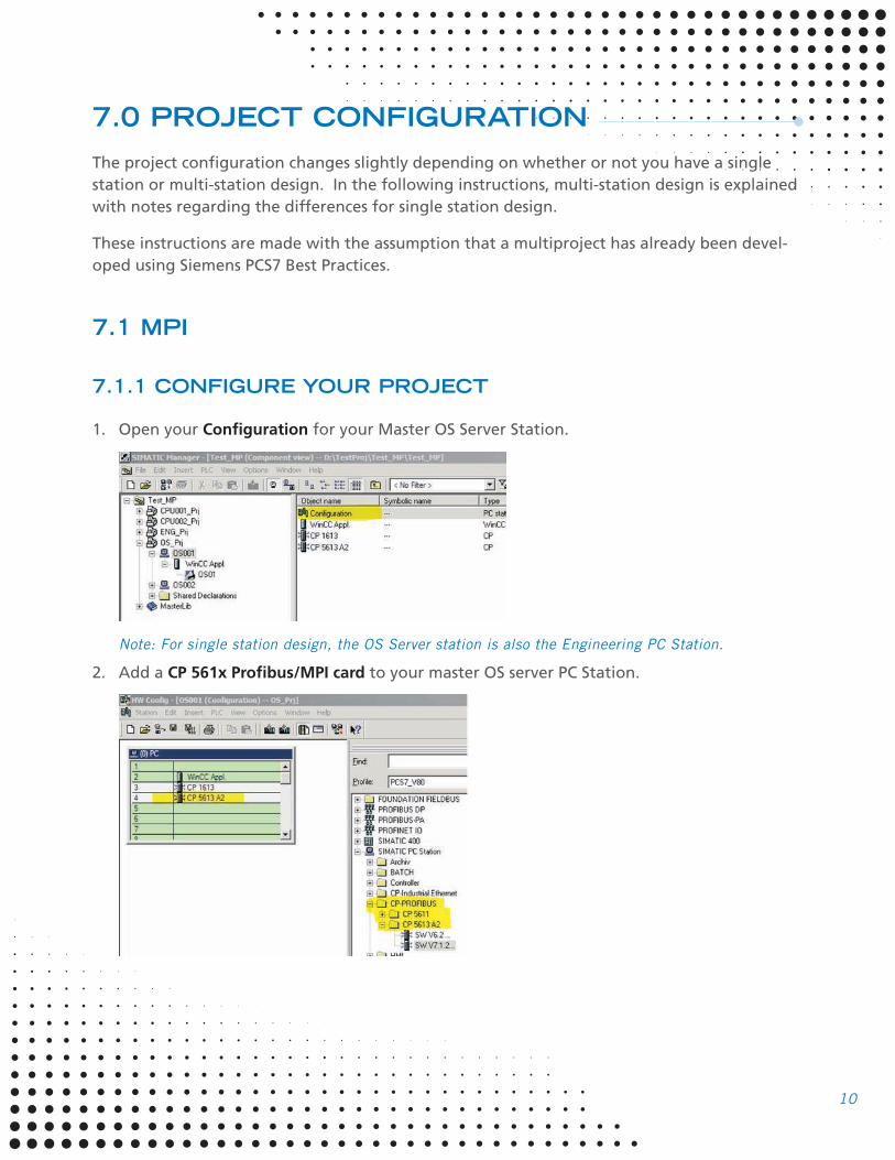
1. Open your Configuration for your Master OS Server Station.
Note: For single station design, the OS Server station is also the Engineering PC Station.
2. Add a CP 561x Profibus/MPI card to your master OS server PC Station.

11
3. Within this dialog, be sure the Type is MPI, a unique address is defined, and the interface is
“networked”. If no network has been created, then create one by pressing the Properties
button. When finished, press OK.
Note: A unique address must be defined even if your OS and AS are in separate projects within
your multiproject. This is due to a later step to merge your MPI buses into one “plant-wide” bus.
4. Open Hardware Configuration for the AS (CPU).
Note: If you are using a PCS7 Box, the AS station is also the Engineering PC Station.
5. Find the MPI/DP interface on the CPU card and double-click.
12
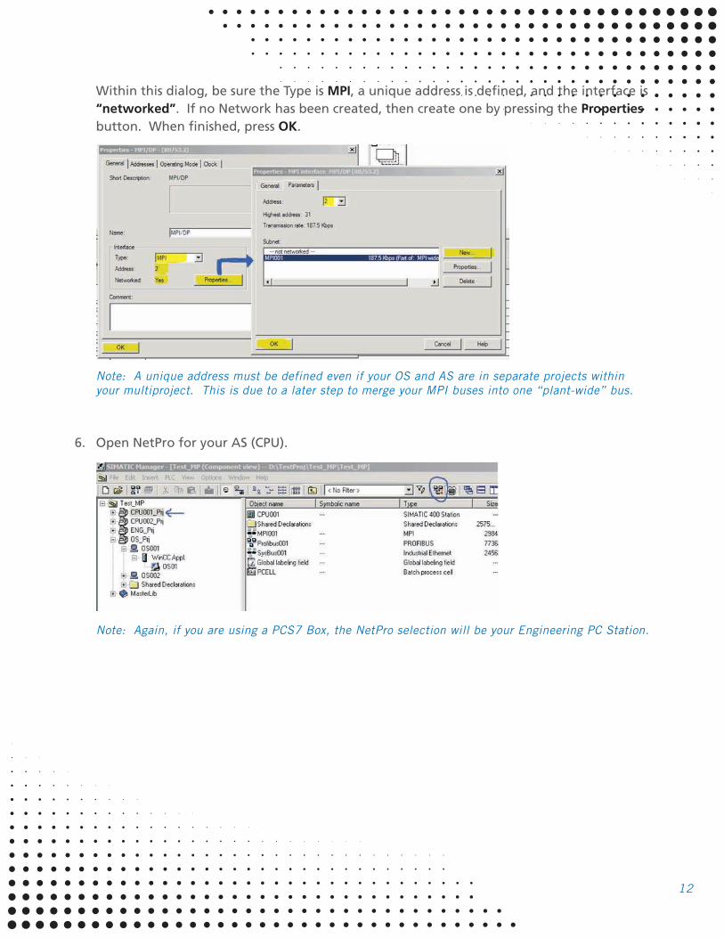
Within this dialog, be sure the Type is MPI, a unique address is defined, and the interface is
“networked”. If no Network has been created, then create one by pressing the Properties
button. When finished, press OK.
Note: A unique address must be defined even if your OS and AS are in separate projects within
your multiproject. This is due to a later step to merge your MPI buses into one “plant-wide” bus.
6. Open NetPro for your AS (CPU).
Note: Again, if you are using a PCS7 Box, the NetPro selection will be your Engineering PC Station.
13
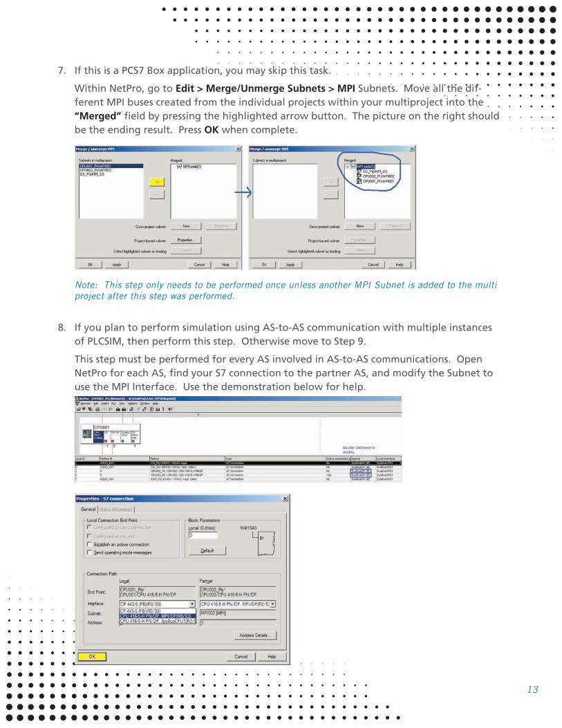
7. If this is a PCS7 Box application, you may skip this task.
Within NetPro, go to Edit > Merge/Unmerge Subnets > MPI Subnets. Move all the dif-
ferent MPI buses created from the individual projects within your multiproject into the
“Merged” field by pressing the highlighted arrow button. The picture on the right should
be the ending result. Press OK when complete.
Note: This step only needs to be performed once unless another MPI Subnet is added to the multi
project after this step was performed.
8. If you plan to perform simulation using AS-to-AS communication with multiple instances
of PLCSIM, then perform this step. Otherwise move to Step 9.
This step must be performed for every AS involved in AS-to-AS communications. Open
NetPro for each AS, find your S7 connection to the partner AS, and modify the Subnet to
use the MPI Interface. Use the demonstration below for help.
14
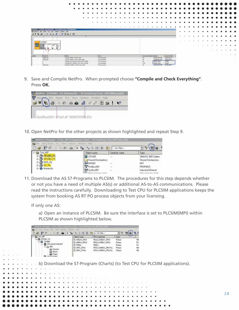
9. Save and Compile NetPro. When prompted choose “Compile and Check Everything”.
Press OK.
10. Open NetPro for the other projects as shown highlighted and repeat Step 9.
11. Download the AS S7-Programs to PLCSIM. The procedures for this step depends whether
or not you have a need of multiple AS(s) or additional AS-to-AS communications. Please
read the instructions carefully. Downloading to Test CPU for PLCSIM applications keeps the
system from booking AS RT PO process objects from your licensing.
If only one AS:
a) Open an instance of PLCSIM. Be sure the interface is set to PLCSIM(MPI) within
PLCSIM as shown highlighted below.
b) Download the S7-Program (Charts) (to Test CPU for PLCSIM applications).
15
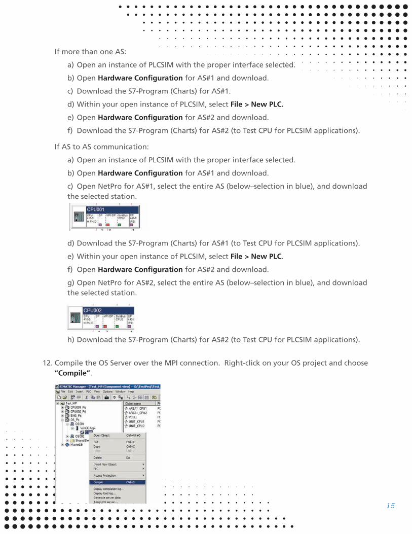
If more than one AS:
a) Open an instance of PLCSIM with the proper interface selected.
b) Open Hardware Configuration for AS#1 and download.
c) Download the S7-Program (Charts) for AS#1.
d) Within your open instance of PLCSIM, select File > New PLC.
e) Open Hardware Configuration for AS#2 and download.
f) Download the S7-Program (Charts) for AS#2 (to Test CPU for PLCSIM applications).
If AS to AS communication:
a) Open an instance of PLCSIM with the proper interface selected.
b) Open Hardware Configuration for AS#1 and download.
c) Open NetPro for AS#1, select the entire AS (below–selection in blue), and download
the selected station.
d) Download the S7-Program (Charts) for AS#1 (to Test CPU for PLCSIM applications).
e) Within your open instance of PLCSIM, select File > New PLC.
f) Open Hardware Configuration for AS#2 and download.
g) Open NetPro for AS#2, select the entire AS (below–selection in blue), and download
the selected station.
h) Download the S7-Program (Charts) for AS#2 (to Test CPU for PLCSIM applications).
12. Compile the OS Server over the MPI connection. Right-click on your OS project and choose
“Compile”.
16
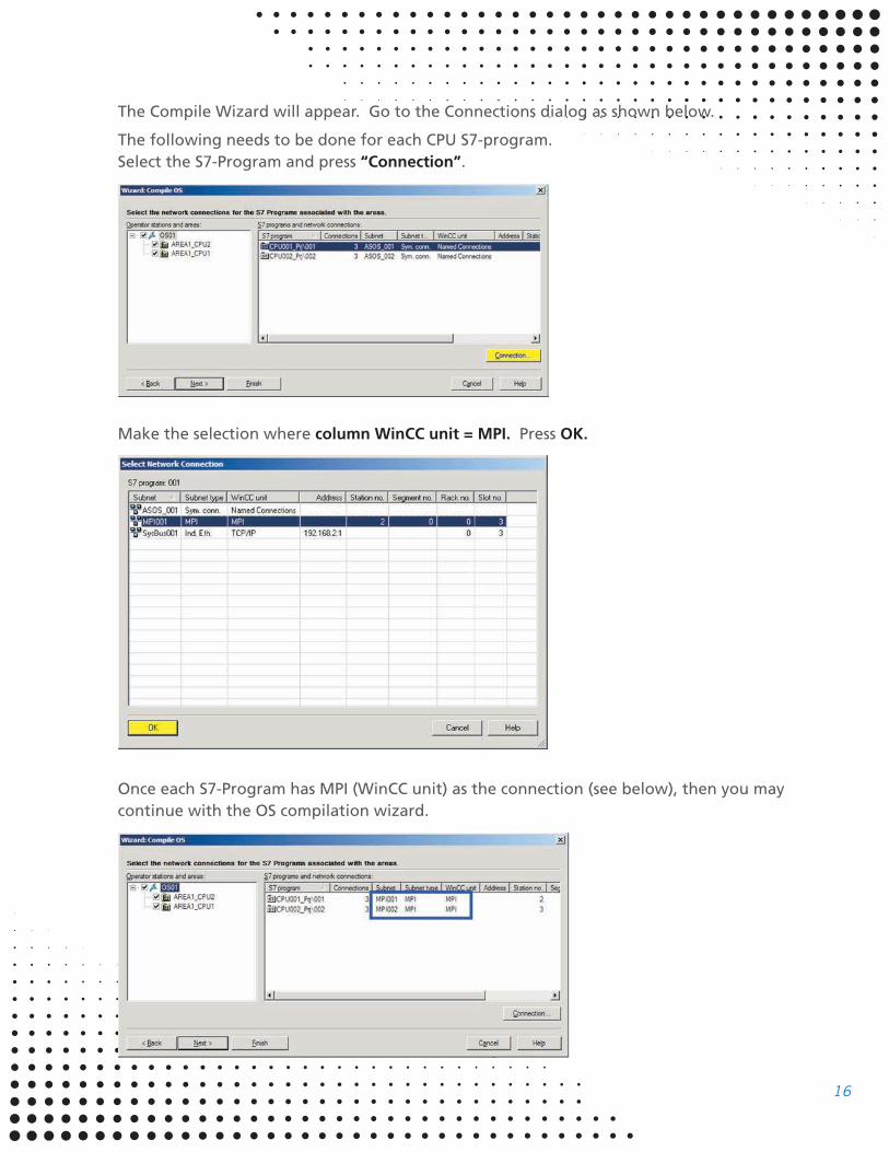
The Compile Wizard will appear. Go to the Connections dialog as shown below.
The following needs to be done for each CPU S7-program.
Select the S7-Program and press “Connection”.
Make the selection where column WinCC unit = MPI. Press OK.
Once each S7-Program has MPI (WinCC unit) as the connection (see below), then you may
continue with the OS compilation wizard.
17
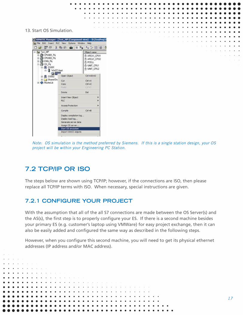
13. Start OS Simulation.
Note: OS simulation is the method preferred by Siemens. If this is a single station design, your OS
project will be within your Engineering PC Station.
7.2 TCP/IP OR ISO
The steps below are shown using TCP/IP; however, if the connections are ISO, then please
replace all TCP/IP terms with ISO. When necessary, special instructions are given.
7.2.1 CONFIGURE YOUR PROJECT
With the assumption that all of the all S7 connections are made between the OS Server(s) and
the AS(s), the first step is to properly configure your ES. If there is a second machine besides
your primary ES (e.g. customer’s laptop using VMWare) for easy project exchange, then it can
also be easily added and configured the same way as described in the following steps.
However, when you configure this second machine, you will need to get its physical ethernet
addresses (IP address and/or MAC address).
18
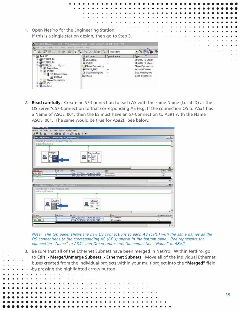
1. Open NetPro for the Engineering Station.
If this is a single station design, then go to Step 3.
2. Read carefully: Create an S7-Connection to each AS with the same Name (Local ID) as the
OS Server’s S7-Connection to that corresponding AS (e.g. If the connection OS to AS#1 has
a Name of ASOS_001, then the ES must have an S7-Connection to AS#1 with the Name
ASOS_001. The same would be true for AS#2). See below.
Note: The top panel shows the new ES connections to each AS (CPU) with the same names as the
OS connections to the corresponding AS (CPU) shown in the bottom pane. Red represents the
connection “Name” to AS#1 and Green represents the connection “Name” to AS#2.
3. Be sure that all of the Ethernet Subnets have been merged in NetPro. Within NetPro, go
to Edit > Merge/Unmerge Subnets > Ethernet Subnets. Move all of the individual Ethernet
buses created from the individual projects within your multiproject into the “Merged” field
by pressing the highlighted arrow button.

19
The picture on the right should be the ending result. Press OK when complete.
Note: This step has usually been completed during project creation. If so, you may skip this step.
4. Save and Compile NetPro for all stations. When prompted, choose the option “Compile
and check everything”. NetPro for the OS should not need compiling since there were no
modifications.
5. If not already complete, Configure and Download your ES PC Station; otherwise,
go to Step 6.
CONFIGURE DOWNLOAD
20
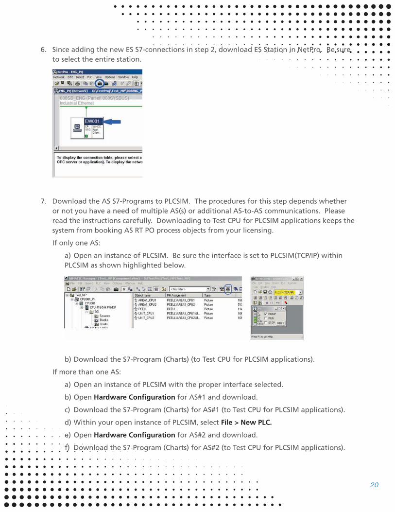
6. Since adding the new ES S7-connections in step 2, download ES Station in NetPro. Be sure
to select the entire station.
7. Download the AS S7-Programs to PLCSIM. The procedures for this step depends whether
or not you have a need of multiple AS(s) or additional AS-to-AS communications. Please
read the instructions carefully. Downloading to Test CPU for PLCSIM applications keeps the
system from booking AS RT PO process objects from your licensing.
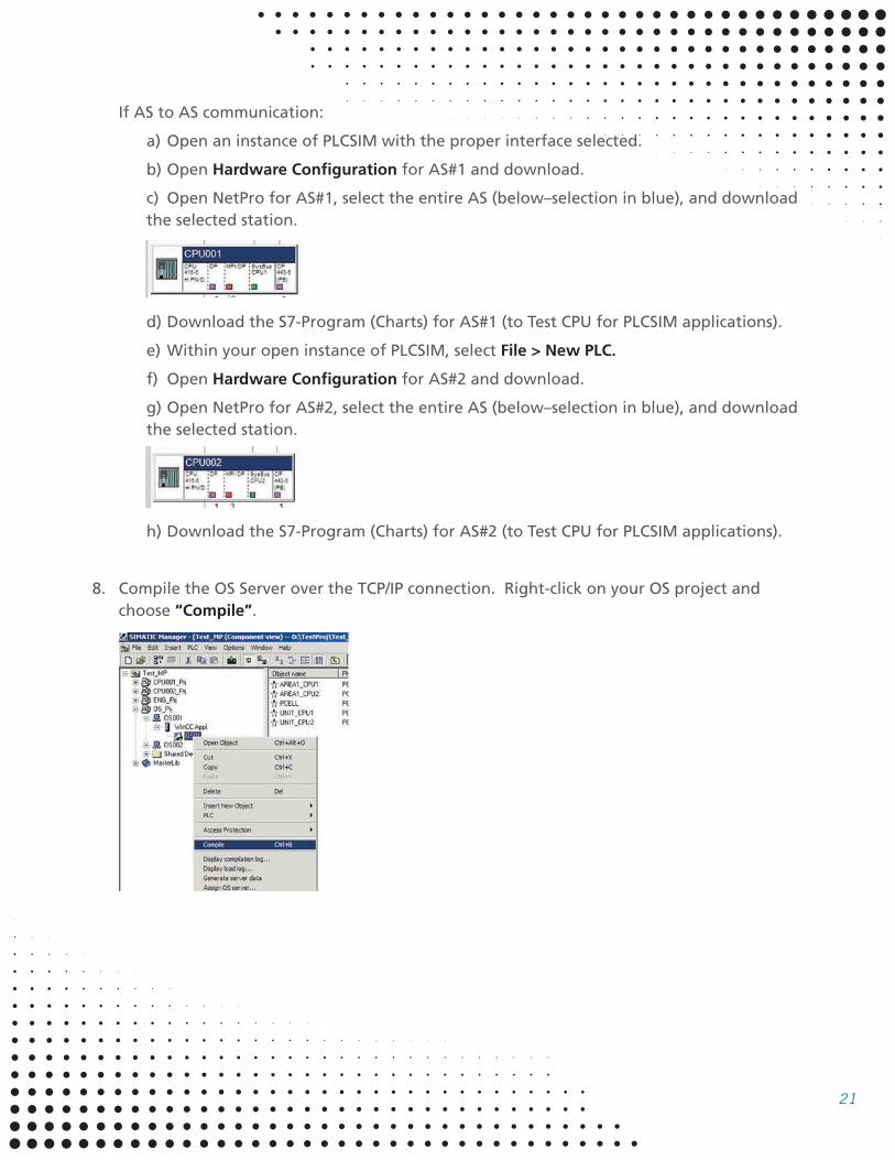
If only one AS:
a) Open an instance of PLCSIM. Be sure the interface is set to PLCSIM(TCP/IP) within
PLCSIM as shown highlighted below.
b) Download the S7-Program (Charts) (to Test CPU for PLCSIM applications).
If more than one AS:
a) Open an instance of PLCSIM with the proper interface selected.
b) Open Hardware Configuration for AS#1 and download.
c) Download the S7-Program (Charts) for AS#1 (to Test CPU for PLCSIM applications).
d) Within your open instance of PLCSIM, select File > New PLC.
e) Open Hardware Configuration for AS#2 and download.
f) Download the S7-Program (Charts) for AS#2 (to Test CPU for PLCSIM applications).
21
If AS to AS communication:
a) Open an instance of PLCSIM with the proper interface selected.
b) Open Hardware Configuration for AS#1 and download.
c) Open NetPro for AS#1, select the entire AS (below–selection in blue), and download
the selected station.
d) Download the S7-Program (Charts) for AS#1 (to Test CPU for PLCSIM applications).
e) Within your open instance of PLCSIM, select File > New PLC.
f) Open Hardware Configuration for AS#2 and download.
g) Open NetPro for AS#2, select the entire AS (below–selection in blue), and download
the selected station.
h) Download the S7-Program (Charts) for AS#2 (to Test CPU for PLCSIM applications).
8. Compile the OS Server over the TCP/IP connection. Right-click on your OS project and
choose “Compile”.
22
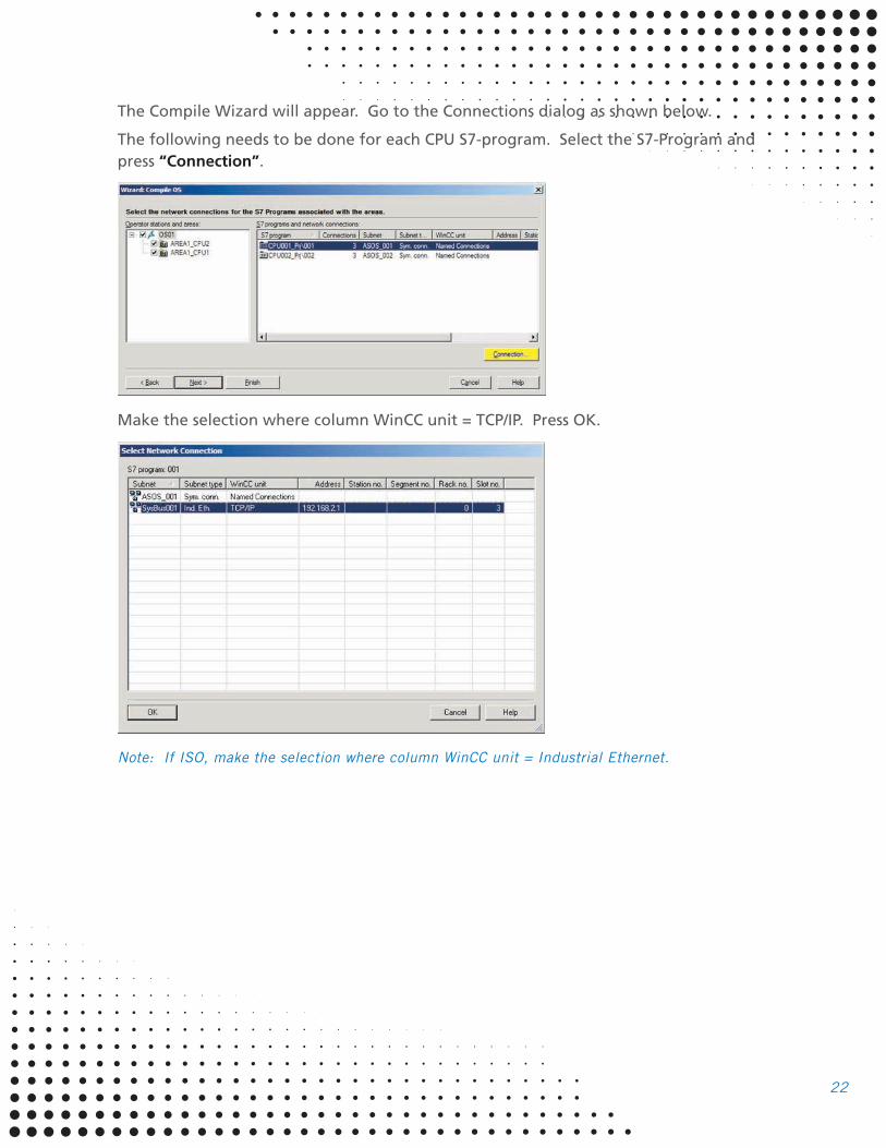
The Compile Wizard will appear. Go to the Connections dialog as shown below.
The following needs to be done for each CPU S7-program. Select the S7-Program and
press “Connection”.
Make the selection where column WinCC unit = TCP/IP. Press OK.
Note: If ISO, make the selection where column WinCC unit = Industrial Ethernet.

23
Once each S7-Program has TCP/IP (WinCC unit) as the connection (see below), then you
may continue with the OS compilation wizard.
Note: If ISO, then column WinCC unit should = Industrial Ethernet.
9. Change the TCP/IP Logical Device Name within Tag Management.
a) Open WinCC Explorer.
b) Within Tag Management, Right-click on TCP/IP and choose System Parameter.
Note: If ISO, then Right-Click on Industrial Ethernet instead. Your S7-programs (001 and 002)
should be beneath rather than beneath TCP/IP.
24
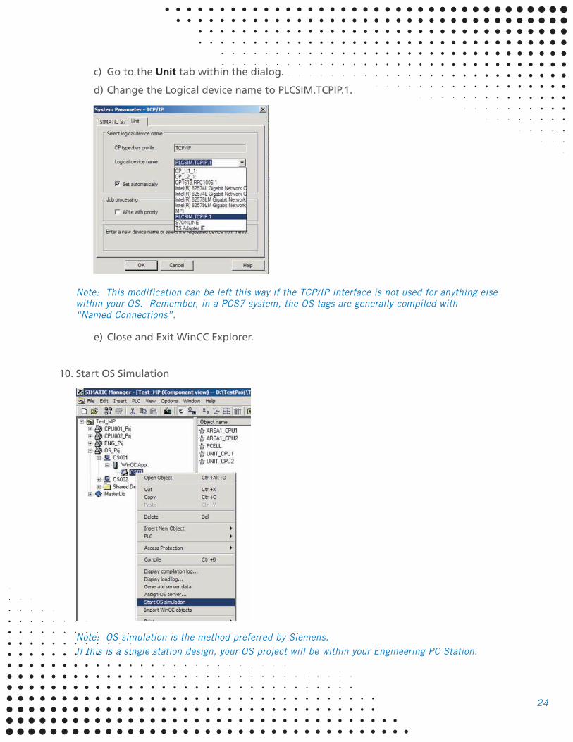
c) Go to the Unit tab within the dialog.
d) Change the Logical device name to PLCSIM.TCPIP.1.
Note: This modification can be left this way if the TCP/IP interface is not used for anything else
within your OS. Remember, in a PCS7 system, the OS tags are generally compiled with
“Named Connections”.
e) Close and Exit WinCC Explorer.
10. Start OS Simulation
Note: OS simulation is the method preferred by Siemens.
If this is a single station design, your OS project will be within your Engineering PC Station.
Related Documents