CHAPTER 11-1 Cisco GGSN Release 10.0 Configuration Guide, Cisco IOS Release 12.4(24)YE2 OL-19936-05 11 Configuring QoS on the GGSN This chapter describes how to configure Quality of Service (QoS) functions to differentiate traffic flow through the gateway GPRS support node (GGSN). For complete descriptions of the GGSN commands in this chapter, see Cisco GGSN Command Reference for the Cisco GGSN release you are using. To locate documentation of other commands that appear in this chapter, use the command reference master index or search online. This chapter includes the following sections: • Overview of QoS Support on the GGSN, page 11-1 • Configuring UMTS QoS on the GGSN, page 11-2 • Configuring the GGSN Default QoS as Requested QoS, page 11-13 • Configuring Call Admission Control on the GGSN, page 11-13 • Configuring Per-PDP Policing, page 11-17 • Monitoring and Maintaining QoS on the GGSN, page 11-20 • Configuration Examples, page 11-22 Overview of QoS Support on the GGSN The Cisco GGSN software supports 3G Universal Mobile Telecommunication System (UMTS) QoS. Each GPRS/UMTS packet data protocol (PDP) context request contains a UMTS QoS profile. The implementation of QoS support in the GPRS/UMTS public LAN mobile network (PLMN) varies by the service provider and the available resources in the network. The 3GPP standards define the UMTS QoS classes that can be defined by a UMTS MS. However, the resulting QoS is negotiated and variable within the GPRS/UMTS network backbone according to the implementations of the service provider. UMTS QoS To manage different level of QoS, UMTS has defined the four QoS traffic classes based on delay, jitter, bandwidth, and reliability factors: • Conversational • Streaming • Interactive • Background

Welcome message from author
This document is posted to help you gain knowledge. Please leave a comment to let me know what you think about it! Share it to your friends and learn new things together.
Transcript
Cisco GGSN Release 10.0 OL-19936-05
C H A P T E R 11
Configuring QoS on the GGSNThis chapter describes how to configure Quality of Service (QoS) functions to differentiate traffic flow through the gateway GPRS support node (GGSN).
For complete descriptions of the GGSN commands in this chapter, see Cisco GGSN Command Reference for the Cisco GGSN release you are using. To locate documentation of other commands that appear in this chapter, use the command reference master index or search online.
This chapter includes the following sections:
• Overview of QoS Support on the GGSN, page 11-1
• Configuring UMTS QoS on the GGSN, page 11-2
• Configuring the GGSN Default QoS as Requested QoS, page 11-13
• Configuring Call Admission Control on the GGSN, page 11-13
• Configuring Per-PDP Policing, page 11-17
• Monitoring and Maintaining QoS on the GGSN, page 11-20
• Configuration Examples, page 11-22
Overview of QoS Support on the GGSNThe Cisco GGSN software supports 3G Universal Mobile Telecommunication System (UMTS) QoS. Each GPRS/UMTS packet data protocol (PDP) context request contains a UMTS QoS profile.
The implementation of QoS support in the GPRS/UMTS public LAN mobile network (PLMN) varies by the service provider and the available resources in the network. The 3GPP standards define the UMTS QoS classes that can be defined by a UMTS MS. However, the resulting QoS is negotiated and variable within the GPRS/UMTS network backbone according to the implementations of the service provider.
UMTS QoS
To manage different level of QoS, UMTS has defined the four QoS traffic classes based on delay, jitter, bandwidth, and reliability factors:
• Conversational
• Streaming
• Interactive
• Background
11-1Configuration Guide, Cisco IOS Release 12.4(24)YE2
Chapter 11 Configuring QoS on the GGSN Configuring UMTS QoS on the GGSN
The Cisco GGSN delivers end-to-end UMTS QoS by implementing it using the Cisco IOS QoS differentiated services (Diffserv).
This chapter describes the QoS support that the GGSN provides for the UMTS QoS classes.
Note The Cisco GGSN supports downloading QoS profiles from an AAA server.
If an APN is configured in non-transparent mode, a user is authenticated before the PDP context is created. The GGSN sends an access-request to AAA server containing parameters in the user-provided PCO option, or using anonymous authentication if anonymous user is enabled on APN. In the access-accept from RADIUS, user-specific attributes such as session and idle timeout values can be downloaded and applied to the PDP context. In addition, the QoS profile can be downloaded via the QoS VSA (as defined by 3GPP TS 24.0008).
If a 3GPP QoS profile attribute is received in an access-accept from an AAA server, the GGSN retrieves the attribute and applies it to the PDP context. If the attribute is not valid, or there is a format error in the attribute, it is ignored and the SGSN requested QoS profile is used for QoS negotiation.
The 3GPP QoS attribute has a vendor-id of 10415 and code 5.
Configuring UMTS QoS on the GGSNThis section describes how to configure the UMTS QoS on the GGSN. It includes the following topics:
• Overview of UMTS QoS, page 11-2
• Configuring UMTS QoS Task Lists, page 11-4
• Enabling UMTS QoS Mapping on the GGSN, page 11-4
• Mapping UMTS QoS Traffic Classes to a DiffServ PHB Group, page 11-4
• Assigning a DSCP to a DiffServ PHB Group, page 11-5
• Configuring the DSCP in the Subscriber Datagram, page 11-7
• Configuring the Cisco 7600 Platform GGSN UMTS QoS Requirements, page 11-8
• Verifying the UMTS QoS Configuration, page 11-11
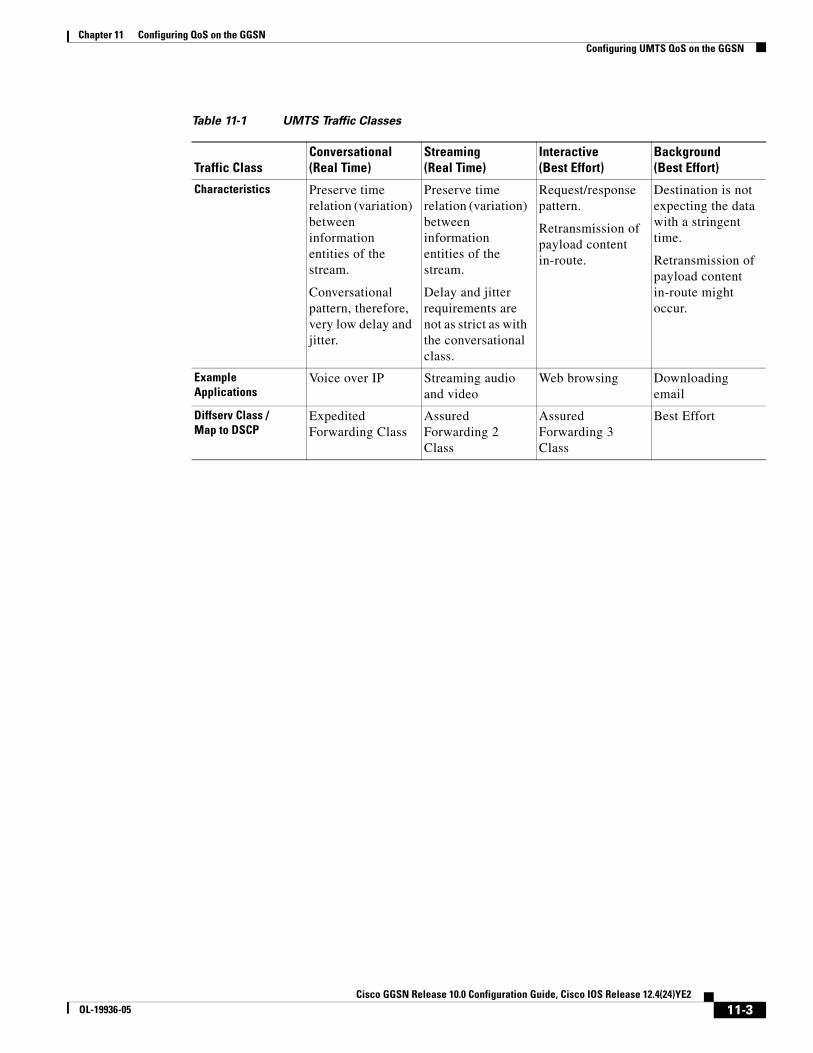
Overview of UMTS QoS3GPP standards define four QoS traffic classes based on delay, jitter, bandwidth, and reliability for UMTS. Table 11-1 describes these UMTS traffic classes and their characteristics, applications, and the mapped Cisco IOS QoS Diffserv class.
11-2Cisco GGSN Release 10.0 Configuration Guide, Cisco IOS Release 12.4(24)YE2
OL-19936-05
Chapter 11 Configuring QoS on the GGSN Configuring UMTS QoS on the GGSN
Table 11-1 UMTS Traffic Classes
Traffic ClassConversational(Real Time)
Streaming(Real Time)
Interactive(Best Effort)
Background(Best Effort)
Characteristics Preserve time relation (variation) between information entities of the stream.
Conversational pattern, therefore, very low delay and jitter.
Preserve time relation (variation) between information entities of the stream.
Delay and jitter requirements are not as strict as with the conversational class.
Request/response pattern.
Retransmission of payload content in-route.
Destination is not expecting the data with a stringent time.
Retransmission of payload content in-route might occur.
Example Applications
Voice over IP Streaming audio and video
Web browsing Downloading email
Diffserv Class / Map to DSCP
Expedited Forwarding Class
Assured Forwarding 2 Class
Assured Forwarding 3 Class
Best Effort
11-3Cisco GGSN Release 10.0 Configuration Guide, Cisco IOS Release 12.4(24)YE2
OL-19936-05

Chapter 11 Configuring QoS on the GGSN Configuring UMTS QoS on the GGSN
The Cisco GGSN supports end-to-end UMTS QoS by implementing it using the Cisco IOS Differentiated Services (DiffServ) model. The DiffServ model is a multiple-service model that can satisfy differing QoS requirements. With DiffServ, the network tries to deliver a particular kind of service based on the QoS specified by each packet. This specification can occur in different ways, for example, using the 6-bit differentiated services code point (DSCP) setting in IP packets or source and destination addresses. The network uses the QoS specification to classify, mark, shape, and police traffic, and to perform intelligent queueing.
For complete information on Cisco IOS QoS and the DiffServ service model, see Cisco IOS Quality of Service Solutions Configuration Guide.
Configuring UMTS QoS Task ListsTo implement the UMTS QoS method on a GGSN, you must first enable the function. From there, you can modify the UMTS QoS options to support your network needs.
Configuring GGSN UMTS QoS on the Cisco 7600 Platform Task List
If configuring UMTS QoS on a GGSN on the Cisco 7600 platform, perform the following tasks:
• Enabling UMTS QoS Mapping on the GGSN, page 11-4 (Required)
• Mapping UMTS QoS Traffic Classes to a DiffServ PHB Group, page 11-4 (Optional)
• Assigning a DSCP to a DiffServ PHB Group, page 11-5 (Optional)
• Configuring the DSCP in the Subscriber Datagram, page 11-7 (Optional)
• Configuring the Cisco 7600 Platform GGSN UMTS QoS Requirements, page 11-8 (Required)
• Configuring Call Admission Control on the GGSN, page 11-13 (Optional)
• Verifying the UMTS QoS Configuration, page 11-11
Enabling UMTS QoS Mapping on the GGSNBy default, UMTS QoS is not enabled on the GGSN. To enable UMTS QoS on the GGSN, use the following command in global configuration mode:
Mapping UMTS QoS Traffic Classes to a DiffServ PHB GroupBefore you can specify a QoS mapping from the UMTS QoS traffic classes to a DiffServ per-hop behavior (PHB) group, you must enable UMTS QoS mapping using the gprs qos map umts command in global configuration mode.
The default mapping values for UMTS QoS traffic classes are as follows:
• Conversational traffic class to the ef-class DiffServ PHB group
• Streaming traffic class to the af2-class DiffServ PHB group
Command Purpose
Router(config)# gprs qos map umts Enables UMTS QoS mapping on the GGSN.
11-4Cisco GGSN Release 10.0 Configuration Guide, Cisco IOS Release 12.4(24)YE2
OL-19936-05

Chapter 11 Configuring QoS on the GGSN Configuring UMTS QoS on the GGSN
• Interactive traffic class to the af3-class DiffServ PHB group
• Background traffic class to the best-effort DiffServ PHB group
If you wish to use mapping values other than these defaults, you can use the gprs umts-qos map traffic-class command to map a UMTS traffic class to another DiffServ PHB group.
Note To successfully map UMTS QoS traffic classes to a DiffServ PHB, the class maps must be configured using the class map and match ip dscp Cisco IOS software commands. For more information about configuring class maps, see Cisco IOS Quality of Service Solutions Configuration Guide.
To map a UMTS traffic class to a DiffServ PHB group, use the following command in global configuration mode:
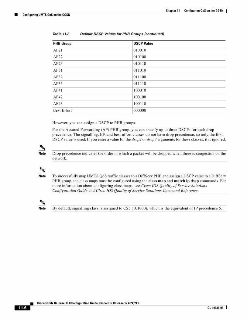
Assigning a DSCP to a DiffServ PHB GroupBy default, the default differentiated services code point (DSCP) value associated with a PHB class is used. Table 11-2 lists the default DSCP values for each PHB group.
Command Purpose
Router(config)# gprs umts-qos map traffic-class traffic-class diffserv-phb-group
Enables mapping of UMTS QoS traffic classes to a DiffServ PHB, where the UMTS traffic classes are:
• signalling
• conversational
• streaming
• interactive
• background
and the DiffServ PHB groups are:
• signalling-class
• ef-class
• af1-class
• af2-class
• af3-class
• af4-class
• best-effort
Table 11-2 Default DSCP Values for PHB Groups
PHB Group DSCP Value
EF 101110
AF11 001010
AF12 001100
AF13 001110
11-5Cisco GGSN Release 10.0 Configuration Guide, Cisco IOS Release 12.4(24)YE2
OL-19936-05
Chapter 11 Configuring QoS on the GGSN Configuring UMTS QoS on the GGSN
However, you can assign a DSCP to PHB groups.
For the Assured Forwarding (AF) PHB group, you can specify up to three DSCPs for each drop precedence. The signalling, EF, and best-effort classes do not have drop precedence, so only the first DSCP value is used. If you enter a value for the dscp2 or dscp3 arguments for these classes, it is ignored.
Note Drop precedence indicates the order in which a packet will be dropped when there is congestion on the network.
Note To successfully map UMTS QoS traffic classes to a DiffServ PHB and assign a DSCP value to a DiffServ PHB group, the class maps must be configured using the class map and match ip dscp commands. For more information about configuring class maps, see Cisco IOS Quality of Service Solutions Configuration Guide and Cisco IOS Quality of Service Solutions Command Reference.
Note By default, signalling class is assigned to CS5 (101000), which is the equivalent of IP precedence 5.
AF21 010010
AF22 010100
AF23 010110
AF31 011010
AF32 011100
AF33 011110
AF41 100010
AF42 100100
AF43 100110
Best Effort 000000
Table 11-2 Default DSCP Values for PHB Groups (continued)
PHB Group DSCP Value
11-6Cisco GGSN Release 10.0 Configuration Guide, Cisco IOS Release 12.4(24)YE2
OL-19936-05

Chapter 11 Configuring QoS on the GGSN Configuring UMTS QoS on the GGSN
To assign a DSCP value to a DiffServ PHB group, use the following command in global configuration mode:
Configuring the DSCP in the Subscriber DatagramBy default, the DSCP in subscriber datagrams is re-marked with the DSCP assigned to the traffic class when the PDP context was created.
To specify that the subscriber datagram be forwarded through the GTP path without modifying its DSCP, use the following command in global configuration mode:
To return to the default value, issue the no gprs umts-qos dscp unmodified command.
Command PurposeRouter(config)# gprs umts-qos map diffserv-phb diffserv-phb-group [dscp1] [dscp2] [dscp3]
Assigns a DSCP to a DiffServ PHB group where the DiffServ PHB groups are:
• signalling
• ef-class
• af1-class
• af2-class
• af3-class
• af4-class
• best-effort
and the DSCPs are:
• dscp1—Required for all classes. Specifies one of 64 DSCP values from 0 to 63. This DSCP value corresponds to drop precedence 1.
• dscp2—(Optional for AF classes) Specifies one of 64 DSCP values from 0 to 63. This DSCP value corresponds to drop precedence 2.
• dscp3—(Optional for AF classes) Specifies one of 64 DSCP values from 0 to 63. This DSCP value corresponds to drop precedence 3.
Command Purpose
Router(config)# gprs umts-qos dscp unmodified [up | down | all]
Specifies that the subscriber datagram be forwarded through the GTP path without modifying its DSCP.
11-7Cisco GGSN Release 10.0 Configuration Guide, Cisco IOS Release 12.4(24)YE2
OL-19936-05

Chapter 11 Configuring QoS on the GGSN Configuring UMTS QoS on the GGSN
Configuring the Cisco 7600 Platform GGSN UMTS QoS RequirementsWhen configuring UMTS QoS for a GGSN running on a Cisco Service and Application Module for IP (SAMI) in the Cisco 7600 platform, the different components of the platform perform different QoS functions. Table 11-3 summarizes the QoS function performed by the Cisco 7600 platform component.
After you configure UMTS QoS on the GGSN, ensure the following tasks are completed:
Supervisor Engine
Note The following list is a summary of the required tasks that need to be completed on the supervisor engine for UMTS QoS on a GGSN. For complete information each of these tasks, see Cisco 7600 Series Cisco IOS Software Configuration Guide.
1. Enable Mutlilayer Switching QoS using the mls qos command in global configuration mode.
Router# mls qos
2. On the supervisor engine, configure aggregate policing for Gi traffic.
Note Because there can be multiple Gn and Gi interfaces, but all the traffic eventually needs to go to a single GE port on the SAMI (one GE port for two GGSNs), we recommend that you use a Named Aggregate Policer to rate limit the traffic to the SAMI. We also recommend dropping all non-conforming traffic.
The following example illustrates the configuration for a named aggregate policer. The named policer is attached to the Gi interface:
Access-list 101 permit ip any any dscp efAccess-list 102 permit ip any any dscp af21Access-list 103 permit ip any any dscp af31Access-list 103 permit ip any any dscp af32Access-list 103 permit ip any any dscp af33Access-list 104 permit ip any any
Class-map match-all conversationalMatch access-group 101
Class-map match-all streamingMatch access-group 102
Class-map match-all interactiveMatch access-group 103
Class-map match-all backgroundMatch access-group 104
Table 11-3 QoS Function by Cisco 7600 Platform Component
Cisco 7600 Component UMTS QoS Function
Catalyst Line Card Classification and ingress and egress scheduling
Supervisor Engine Classification and aggregate policing
Cisco IOS GGSN image on the Cisco SAMI Classification, DSCP marking, and output queuing
11-8Cisco GGSN Release 10.0 Configuration Guide, Cisco IOS Release 12.4(24)YE2
OL-19936-05

Chapter 11 Configuring QoS on the GGSN Configuring UMTS QoS on the GGSN
Mls qos aggregate-policer AGGREGATE-CONV bit-rate1 normal-burst max-burst conform-action transmit exceed-action dropMls qos aggregate-policer AGGREGATE-STREAMING bit-rate1 normal-burst max-burst conform-action transmit exceed-action dropMls qos aggregate-policer AGGREGATE-INTERACTIVE bit-rate1 normal-burst max-burst conform-action transmit exceed-action dropMls qos aggregate-policer AGGREGATE-BACKGROUND bit-rate1 normal-burst max-burst conform-action transmit exceed-action drop
Policy-map Gi-incomingClass conversational
Police aggregate AGGREGATE-CONVClass streaming
Police aggregate AGGREGATE-STREAMINGClass interactive
Police aggregate AGGREGATE-INTERACTIVEClass background
Police aggregate AGGREGATE-BACKGROUND
Router(config-if)# service-policy input Gi-incoming
Note To monitor policing statistics, you can use the following show commands:- show mls qos aggregate-policer name- show policy-map interface interface- show policy interface interface
3. Set the trust state of the ingress ports to trust-dscp mode using the msl qos trust dscp command in interface configuration mode:
Router(config)# interface FastEthernet2/1Router(config-if)# mls qos trust dscp
4. Configure egress port scheduling by completing the following tasks:
a. Obtain the UMTS traffic class-to-DSCP mappings using the show gprs umts-qos traffic class privileged EXEC command on the GGSN running on the Cisco SAMI:
Router# ggsn show gprs umts-qos traffic-class
b. Obtain the default DSCP-to-CoS mapping by displaying the QoS mapping information using the show mls qos maps privileged EXEC command.
Router# show mls qos maps
c. Obtain the default CoS-to-queue mapping by displaying the queueing statistics of an interface using the show queuing interface privileged EXEC command.
Router# show queuing interface interface
11-9Cisco GGSN Release 10.0 Configuration Guide, Cisco IOS Release 12.4(24)YE2
OL-19936-05

Chapter 11 Configuring QoS on the GGSN Configuring UMTS QoS on the GGSN
d. Using the information obtained in Steps A, B, and C, determine if customized egress DSCP-to-CoS mapping is necessary and if so, define the mapping using the mls qos map dscp-cos command in global configuration mode.
Router(config)# mls qos map dscp-cos dscp to cos
When customizing DSCP-CoS mapping, ensure that:
- Conversational and streaming traffic are put into egress queue 4
- Interactive and background traffic are equally distributed between the two normal queues.
- Interactive traffic is mapped to different CoS values so that different thresholds can be configured on the queue to take advantage of WRED.
5. If the line card supports Weighted Random Early Detection WRED, configure congestion avoidance by completing the following tasks:
a. Enable WRED and specify the minimum and maximum threshold for specified queues using the wrr-queue random-detect max-threshold command in interface configuration mode (the defaults are recommended).
Router(config-if)# wrr-queue random-detect max-threshold queue percent-of-queue-size
b. Map CoS values to drop thresholds using the wrr-queue cos map command in interface configuration mode. When the threshold is exceeded, frames with specific CoS values will be dropped.
wrr-queue cos-map queue-id threshold-id cos-1 ... cos-n
In the following example, CoS values 3 and 4 are assigned to transmit queue 1/threshold 2 and transmit 2/threshold 1.
Router(config-if)# wrr-queue cos-map 1 1 3Router(config-if)# wrr-queue cos-map 1 2 4
c. Allocate bandwidth between standard transmit queue 1 (low priority) and standard transmit queue 2 (high priority) using the wrr-queue bandwidth command in interface configuration mode.
Router(config-if)# wrr-queue bandwidth weight1 weight2 weight3
Cisco GGSN
1. Configure an output queueing strategy for the UMTS traffic classes for each GGSN.
You can configure a queueing strategy for each of the UMTS traffic classes for each GGSN.
The following configuration example assumes that the UMTS traffic classes and class maps have been defined.
Interface GigabitEthernet0/0Bandwidth <max-bandwidth>
Service-policy output sami-output
Policy-map sami-outputClass conversational
Priority percent 5Class streaming
Priority percent15Class interactive
Bandwidth 20Class background
11-10Cisco GGSN Release 10.0 Configuration Guide, Cisco IOS Release 12.4(24)YE2
OL-19936-05

Chapter 11 Configuring QoS on the GGSN Configuring UMTS QoS on the GGSN
Bandwidth 20Class signaling
Bandwidth 15
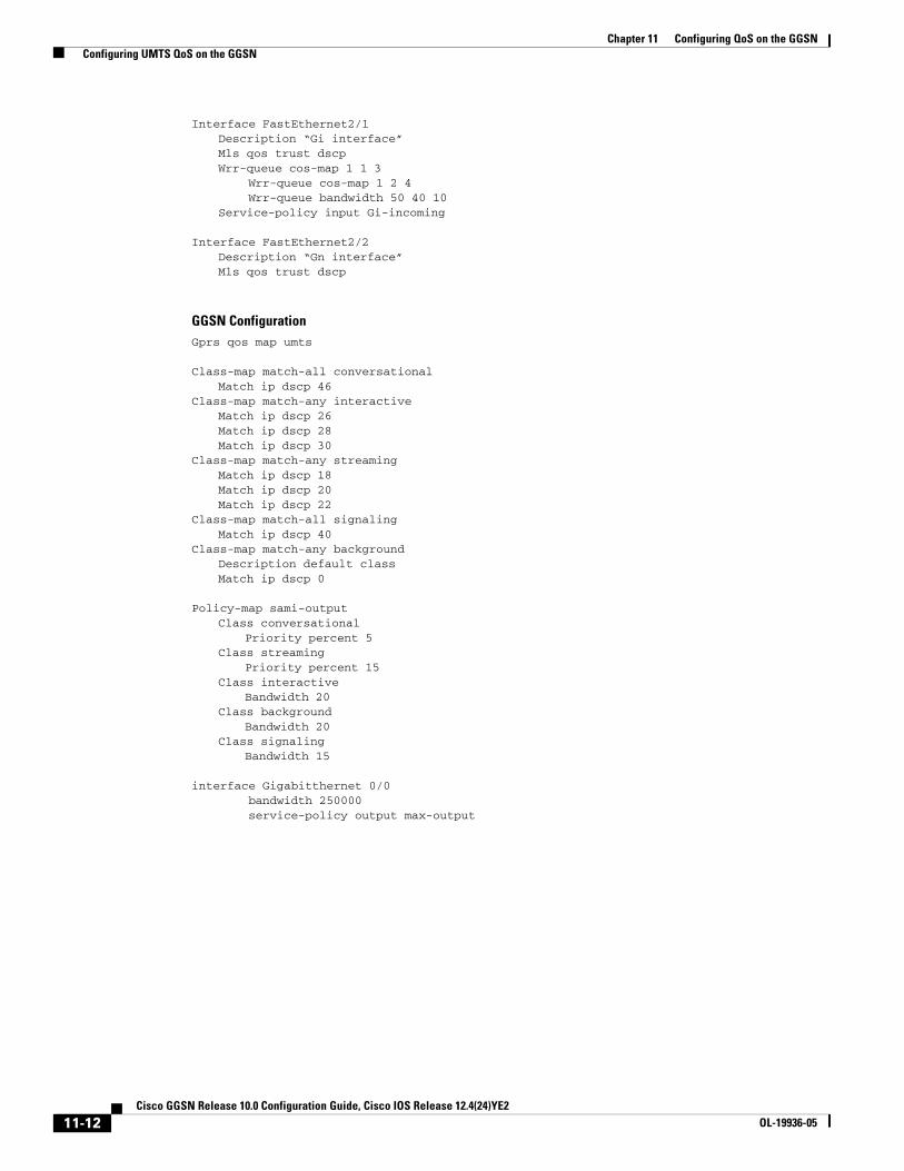
Verifying the UMTS QoS ConfigurationTo verify your UMTS QoS configuration, use the show running-config command on the supervisor engine and the GGSN running on the Cisco SAMI and observe the UMTS QoS parameters in the following example:
Supervisor Engine Configuration:Mls qos
Mls qos map dscp-cos 18 20 22 to 5Mls qos map dscp-cos 26 to 4Mls qos map dscp-cos 28,30 to 3
Access-list 101 permit ip any any dscp efAccess-list 102 permit ip any any dscp af21Access-list 103 permit ip any any dscp af31Access-list 103 permit ip any any dscp af32Access-list 103 permit ip any any dscp af33Access-list 104 permit ip any any
Class-map match-all conversational Match access-group 101Class-map match-all streaming
Match access-group 102Class-map match-all interactive
Match access-group 103Class-map match-all background
Match access-group 104
Mls qos aggregate-policer AGGREGATE-CONV <bit rate1> <normal-burst> <max-burst>Conform-action transmit exceed-action dropMls qos aggregate-policer AGGREGATE-STREAMING <bit rate2> <normal-burst> <max-burst> conform-action transmit exceed-action dropMls qos aggregate-policer AGGREGATE-INTERACTIVE <bit rate3> <normal-burst> <max-burst> conform-action transmit exceed-action dropMls qos aggregate-policer AGGREGATE-BACKGROUND <bit rate4> <normal-burst> <max-burst> conform-action transmit exceed-action drop
Policy-map Gi-incomingClass conversational
Police aggregate AGGREGATE-CONVClass streaming
Police aggregate AGGREGATE-STREAMINGClass interactive
Police aggregate AGGREGATE-INTERACTIVEClass background
Police aggregate AGGREGATE-BACKGROUND
11-11Cisco GGSN Release 10.0 Configuration Guide, Cisco IOS Release 12.4(24)YE2
OL-19936-05
Chapter 11 Configuring QoS on the GGSN Configuring UMTS QoS on the GGSN
Interface FastEthernet2/1Description “Gi interface”Mls qos trust dscpWrr-queue cos-map 1 1 3
Wrr-queue cos-map 1 2 4 Wrr-queue bandwidth 50 40 10
Service-policy input Gi-incoming
Interface FastEthernet2/2Description “Gn interface”Mls qos trust dscp
GGSN ConfigurationGprs qos map umts
Class-map match-all conversationalMatch ip dscp 46
Class-map match-any interactiveMatch ip dscp 26Match ip dscp 28Match ip dscp 30
Class-map match-any streamingMatch ip dscp 18Match ip dscp 20Match ip dscp 22
Class-map match-all signalingMatch ip dscp 40
Class-map match-any backgroundDescription default classMatch ip dscp 0
Policy-map sami-outputClass conversational
Priority percent 5Class streaming
Priority percent 15Class interactive
Bandwidth 20Class background
Bandwidth 20Class signaling
Bandwidth 15
interface Gigabitthernet 0/0 bandwidth 250000 service-policy output max-output
11-12Cisco GGSN Release 10.0 Configuration Guide, Cisco IOS Release 12.4(24)YE2
OL-19936-05

Chapter 11 Configuring QoS on the GGSN Configuring the GGSN Default QoS as Requested QoS
Configuring the GGSN Default QoS as Requested QoSIf you are not using UMTS QoS mapping on the GGSN, you can configure the GGSN to set its default QoS values in the response message exactly as requested in the Create PDP Context request. By using this command, you can prevent the GGSN from lowering the requested QoS.
To configure the GGSN to set the requested QoS as the default QoS, use the following command, beginning in global configuration mode:
Note When the gprs qos default-response requested command is not configured, and GPRS canonical QoS is not enabled, the GGSN sets its default QoS class to best effort.
Configuring Call Admission Control on the GGSNThe Call Admission Control (CAC) feature on the GGSN ensures that required network resources are available for real-time data traffic such as voice and video. CAC is applied at the APN and consists of two functions: maximum QoS authorization and bandwidth management.
The following sections describe how to configure these functions on the GGSN:
• Configuring Maximum QoS Authorization, page 11-13
• Configuring Bandwidth Management, page 11-16
• Configuration Examples, page 11-22
• CAC Configuration Example, page 11-24
Note CAC on the GGSN requires that UMTS QoS is enabled using the gprs qos map umts command in global configuration mode, and that traffic class criterion and traffic policies have been created.
Configuring Maximum QoS AuthorizationThe CAC maximum QoS authorization function ensures that the QoS requested by a Create PDP Context does not exceed the maximum QoS configured within an APN. Using a CAC maximum QoS policy, you define certain QoS parameters within a policy and attach the policy to an APN. The CAC maximum QoS policy limits the QoS requested by the PDP during its creation and modification process.
Note A CAC maximum QoS policy can be attached to multiple APNs.
Command PurposeRouter(config)# gprs qos default-response requested (Optional) Specifies that the GGSN sets its default QoS
values in the response message exactly as requested in the Create PDP Context request.
11-13Cisco GGSN Release 10.0 Configuration Guide, Cisco IOS Release 12.4(24)YE2
OL-19936-05
Chapter 11 Configuring QoS on the GGSN Configuring Call Admission Control on the GGSN
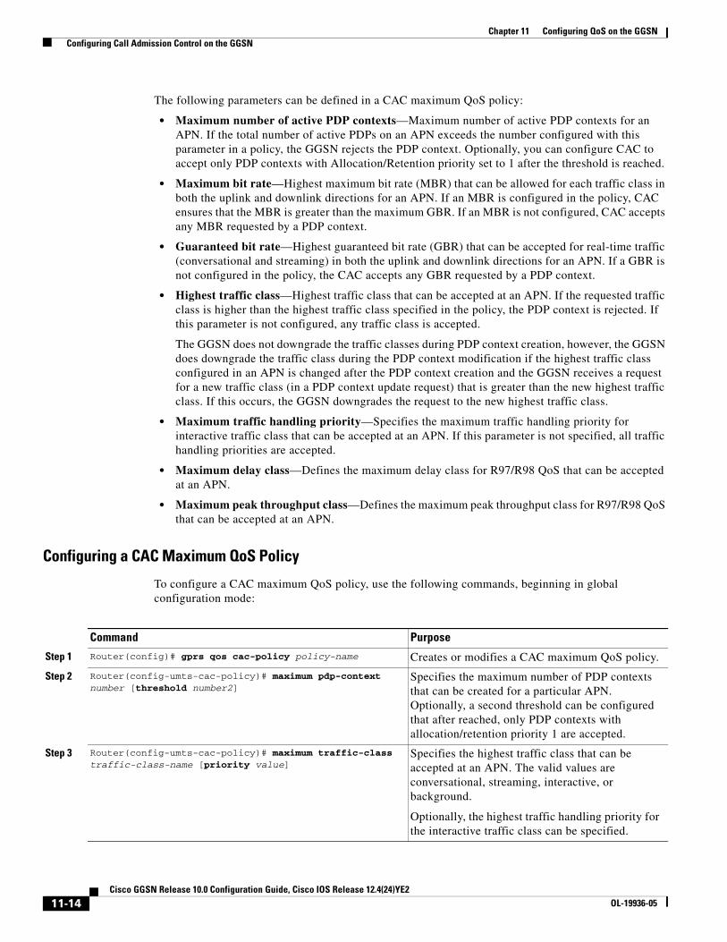
The following parameters can be defined in a CAC maximum QoS policy:
• Maximum number of active PDP contexts—Maximum number of active PDP contexts for an APN. If the total number of active PDPs on an APN exceeds the number configured with this parameter in a policy, the GGSN rejects the PDP context. Optionally, you can configure CAC to accept only PDP contexts with Allocation/Retention priority set to 1 after the threshold is reached.
• Maximum bit rate—Highest maximum bit rate (MBR) that can be allowed for each traffic class in both the uplink and downlink directions for an APN. If an MBR is configured in the policy, CAC ensures that the MBR is greater than the maximum GBR. If an MBR is not configured, CAC accepts any MBR requested by a PDP context.
• Guaranteed bit rate—Highest guaranteed bit rate (GBR) that can be accepted for real-time traffic (conversational and streaming) in both the uplink and downlink directions for an APN. If a GBR is not configured in the policy, the CAC accepts any GBR requested by a PDP context.
• Highest traffic class—Highest traffic class that can be accepted at an APN. If the requested traffic class is higher than the highest traffic class specified in the policy, the PDP context is rejected. If this parameter is not configured, any traffic class is accepted.
The GGSN does not downgrade the traffic classes during PDP context creation, however, the GGSN does downgrade the traffic class during the PDP context modification if the highest traffic class configured in an APN is changed after the PDP context creation and the GGSN receives a request for a new traffic class (in a PDP context update request) that is greater than the new highest traffic class. If this occurs, the GGSN downgrades the request to the new highest traffic class.
• Maximum traffic handling priority—Specifies the maximum traffic handling priority for interactive traffic class that can be accepted at an APN. If this parameter is not specified, all traffic handling priorities are accepted.
• Maximum delay class—Defines the maximum delay class for R97/R98 QoS that can be accepted at an APN.
• Maximum peak throughput class—Defines the maximum peak throughput class for R97/R98 QoS that can be accepted at an APN.
Configuring a CAC Maximum QoS Policy
To configure a CAC maximum QoS policy, use the following commands, beginning in global configuration mode:
Command Purpose
Step 1 Router(config)# gprs qos cac-policy policy-name Creates or modifies a CAC maximum QoS policy.
Step 2 Router(config-umts-cac-policy)# maximum pdp-context number [threshold number2]
Specifies the maximum number of PDP contexts that can be created for a particular APN. Optionally, a second threshold can be configured that after reached, only PDP contexts with allocation/retention priority 1 are accepted.
Step 3 Router(config-umts-cac-policy)# maximum traffic-class traffic-class-name [priority value]
Specifies the highest traffic class that can be accepted at an APN. The valid values are conversational, streaming, interactive, or background.
Optionally, the highest traffic handling priority for the interactive traffic class can be specified.
11-14Cisco GGSN Release 10.0 Configuration Guide, Cisco IOS Release 12.4(24)YE2
OL-19936-05

Chapter 11 Configuring QoS on the GGSN Configuring Call Admission Control on the GGSN
Enabling the CAC Maximum QoS Policy Function and Attaching a Policy to an APN
To enable the CAC maximum QoS policy function and attach a policy to an APN, use the following command in access-point configuration mode:
Step 4 Router(config-umts-cac-policy)# maximum peak-throughput value [reject]
Defines the maximum peak throughput for R97/R98 QoS that can be accepted at an APN. The valid values are between 1 and 9.
By default, PDP contexts for which the peak throughput is higher than the configured value are downgraded to the configured value. Optionally, you can specify the reject keyword to have these PDP contexts rejected instead.
Step 5 Router(config-umts-cac-policy)# maximum delay-class value [reject]
Specifies the maximum delay class for R97/R98 QoS that can be accepted at an APN.
By default, PDP contexts for which the maximum delay-class is higher than the configured value are downgraded to the configured value. Optionally, you can specify the reject keyword to have these PDP contexts rejected instead.
Step 6 Router(config-umts-cac-policy)# mbr traffic-class traffic-class-name bitrate {uplink | downlink} [reject]
Specifies the maximum bit rate (MBR) that can be allowed for each traffic class in both directions (downlink and uplink). The valid value is between 1 and 256000.
Optionally, using the reject keyword option, you can specify for Create PDP Context requests to be rejected when the MBR exceeds the configured value.
Step 7 Router(config-umts-cac-policy)# gbr traffic-class traffic-class-name bitrate {uplink | downlink} [reject]
Specifies the highest guaranteed bit rate (GBR) that can be allowed in uplink and downlink directions for real-time classes (conversational and streaming) at an APN. The valid value is between 1 and 1 and 256000.
Optionally, using the reject keyword option, you can specify for Create PDP Context requests to be rejected when the GBR exceeds the configured value.
Command Purpose
Command PurposeRouter(config-access-point)# cac-policy Enables the maximum QoS policy function of the CAC
feature and applies a policy to an APN.
11-15Cisco GGSN Release 10.0 Configuration Guide, Cisco IOS Release 12.4(24)YE2
OL-19936-05
Chapter 11 Configuring QoS on the GGSN Configuring Call Admission Control on the GGSN
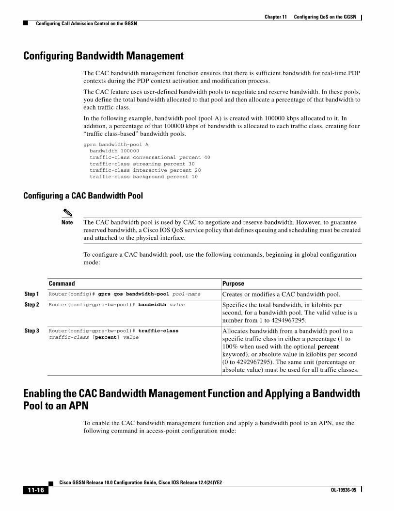
Configuring Bandwidth ManagementThe CAC bandwidth management function ensures that there is sufficient bandwidth for real-time PDP contexts during the PDP context activation and modification process.
The CAC feature uses user-defined bandwidth pools to negotiate and reserve bandwidth. In these pools, you define the total bandwidth allocated to that pool and then allocate a percentage of that bandwidth to each traffic class.
In the following example, bandwidth pool (pool A) is created with 100000 kbps allocated to it. In addition, a percentage of that 100000 kbps of bandwidth is allocated to each traffic class, creating four “traffic class-based” bandwidth pools.
gprs bandwidth-pool Abandwidth 100000traffic-class conversational percent 40traffic-class streaming percent 30traffic-class interactive percent 20traffic-class background percent 10
Configuring a CAC Bandwidth Pool
Note The CAC bandwidth pool is used by CAC to negotiate and reserve bandwidth. However, to guarantee reserved bandwidth, a Cisco IOS QoS service policy that defines queuing and scheduling must be created and attached to the physical interface.
To configure a CAC bandwidth pool, use the following commands, beginning in global configuration mode:
Enabling the CAC Bandwidth Management Function and Applying a Bandwidth Pool to an APN
To enable the CAC bandwidth management function and apply a bandwidth pool to an APN, use the following command in access-point configuration mode:
Command Purpose
Step 1 Router(config)# gprs qos bandwidth-pool pool-name Creates or modifies a CAC bandwidth pool.
Step 2 Router(config-gprs-bw-pool)# bandwidth value Specifies the total bandwidth, in kilobits per second, for a bandwidth pool. The valid value is a number from 1 to 4294967295.
Step 3 Router(config-gprs-bw-pool)# traffic-class traffic-class [percent] value
Allocates bandwidth from a bandwidth pool to a specific traffic class in either a percentage (1 to 100% when used with the optional percent keyword), or absolute value in kilobits per second (0 to 4292967295). The same unit (percentage or absolute value) must be used for all traffic classes.
11-16Cisco GGSN Release 10.0 Configuration Guide, Cisco IOS Release 12.4(24)YE2
OL-19936-05
Chapter 11 Configuring QoS on the GGSN Configuring Per-PDP Policing
Note A CAC bandwidth pool can be applied to multiple APNs.
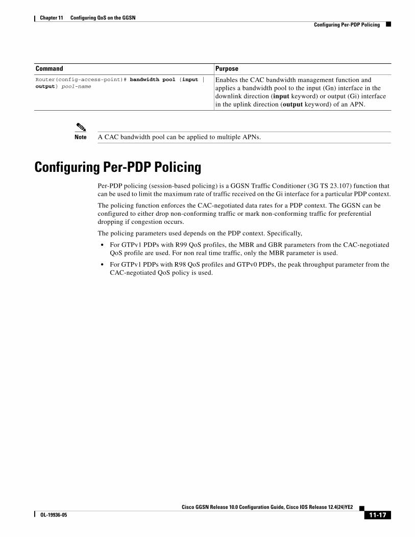
Configuring Per-PDP PolicingPer-PDP policing (session-based policing) is a GGSN Traffic Conditioner (3G TS 23.107) function that can be used to limit the maximum rate of traffic received on the Gi interface for a particular PDP context.
The policing function enforces the CAC-negotiated data rates for a PDP context. The GGSN can be configured to either drop non-conforming traffic or mark non-conforming traffic for preferential dropping if congestion occurs.
The policing parameters used depends on the PDP context. Specifically,
• For GTPv1 PDPs with R99 QoS profiles, the MBR and GBR parameters from the CAC-negotiated QoS profile are used. For non real time traffic, only the MBR parameter is used.
• For GTPv1 PDPs with R98 QoS profiles and GTPv0 PDPs, the peak throughput parameter from the CAC-negotiated QoS policy is used.
Command Purpose
Router(config-access-point)# bandwidth pool {input | output} pool-name
Enables the CAC bandwidth management function and applies a bandwidth pool to the input (Gn) interface in the downlink direction (input keyword) or output (Gi) interface in the uplink direction (output keyword) of an APN.
11-17Cisco GGSN Release 10.0 Configuration Guide, Cisco IOS Release 12.4(24)YE2
OL-19936-05

Chapter 11 Configuring QoS on the GGSN Configuring Per-PDP Policing
RestrictionsThe following restrictions apply to per-PDP policing:
• Per-PDP policing is supported for IPv4 PDP contexts only.
• UMTS QoS mapping must be enabled on the GGSN.
• Cisco Express Forwarding (CEF) must be enabled on Gi interface.
• Per-PDP policing is supported for downlink traffic at the Gi interface only.
• The initial packets of a PDP context are not policed.
• Hiearchical policing is not supported.
• If flow-based policing is configured in a policy map that is attached to an APN, the show policy-map apn command displays the total number of packets received before policing and does not display the policing counters.
• A service policy that is applied to an APN cannot be modified. To modify a service policy, remove the service policy from the APN, modify it, and then re-apply it.
• Multiple class maps, each with match flow pdp configured and a different differentiated services code point (DSCP), are supported in a policy map only if the DSCP is trusted (the gprs umts-qos dscp unmodified command in global configuration mode has not been configured on the GGSN).
Per-PDP Policing Configuration Task ListTo configure per-PDP policing on the GGSN, perform the following tasks:
• Creating a Class Map with PDP Flows as the Match Criterion, page 11-18
• Creating a Policy Map and Configuring Traffic Policing, page 11-19
• Attaching the Policy to an APN, page 11-20
• Resetting APN Policing Statistics, page 11-20
Creating a Class Map with PDP Flows as the Match Criterion To create a class match and specify PDP flows as the match criterion, use the following commands, beginning in global configuration mode:
Note Do no specify the match-any option when defining a class for PDP flow classification. The default is match-all.
Command Purpose
Step 1 Router(config)# class-map class-map-name Creates a class map to use for matching packets.
Step 2 Router(config-cmap)# match flow pdp Specifies PDP flows as the match criterion in a class map.
Step 3 Router(config-cmap)# exit Exits class map configuration mode.
11-18Cisco GGSN Release 10.0 Configuration Guide, Cisco IOS Release 12.4(24)YE2
OL-19936-05
Chapter 11 Configuring QoS on the GGSN Creating a Policy Map and Configuring Traffic Policing
Note Additional match criteria can also be configured in the class map. DSCP and precedence-based classifications are supported.
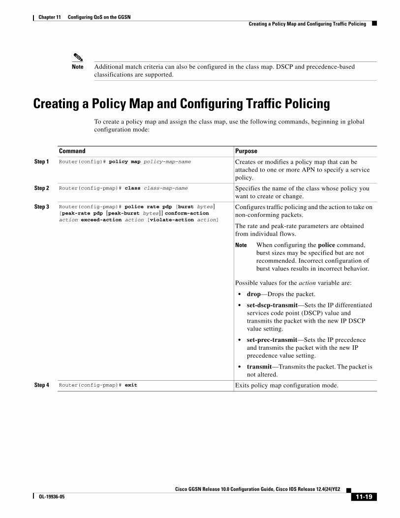
Creating a Policy Map and Configuring Traffic PolicingTo create a policy map and assign the class map, use the following commands, beginning in global configuration mode:
Command Purpose
Step 1 Router(config)# policy map policy-map-name Creates or modifies a policy map that can be attached to one or more APN to specify a service policy.
Step 2 Router(config-pmap)# class class-map-name Specifies the name of the class whose policy you want to create or change.
Step 3 Router(config-pmap)# police rate pdp [burst bytes] [peak-rate pdp [peak-burst bytes]] conform-action action exceed-action action [violate-action action]
Configures traffic policing and the action to take on non-conforming packets.
The rate and peak-rate parameters are obtained from individual flows.
Note When configuring the police command, burst sizes may be specified but are not recommended. Incorrect configuration of burst values results in incorrect behavior.
Possible values for the action variable are:
• drop—Drops the packet.
• set-dscp-transmit—Sets the IP differentiated services code point (DSCP) value and transmits the packet with the new IP DSCP value setting.
• set-prec-transmit—Sets the IP precedence and transmits the packet with the new IP precedence value setting.
• transmit—Transmits the packet. The packet is not altered.
Step 4 Router(config-pmap)# exit Exits policy map configuration mode.
11-19Cisco GGSN Release 10.0 Configuration Guide, Cisco IOS Release 12.4(24)YE2
OL-19936-05

Chapter 11 Configuring QoS on the GGSN Monitoring and Maintaining QoS on the GGSN
Attaching the Policy to an APNTo attach the policy map to an APN, use the following commands, beginning in access-point configuration mode:
Resetting APN Policing StatisticsTo reset policing counters displayed by the show policy-map apn command, use the following command in global configuration mode
Monitoring and Maintaining QoS on the GGSNThis section describes the commands used to display QoS configuration parameters and status on the GGSN. It contains the following information:
• show Command Summary, page 11-20
• Monitoring UMTS QoS, page 11-21
show Command SummaryThis section provides a summary list of the show commands that you can use to monitor GPRS and UMTS QoS on the GGSN. Not all commands provide information for all types of QoS methods on the GGSN.
The following privileged EXEC commands are used to monitor and maintain QoS on the GGSN:
Command Purpose
Step 1 Router(config-)# access-point index Specifies an access point number and enters access-point configuration mode.
Step 2 Router(config-access-point)# service-policy input policy-map-name
Attaches a service policy to an APN to use as the service policy in the downlink direction for PDP flows of that APN.
Step 3 Router(config-access-point)# exit Exits access-point configuration mode.
Command Purpose
Router(config)# clear gprs access-point statistics access-point-index
Clears statistics counters for a specific access point.
Command Purpose
Router# show gprs bandwidth-pool status pool-name Displays a list of configured CAC bandwidth pools, along with their status.
Router# show gprs gtp pdp-context imsi hex-data Displays PDP contexts by international mobile subscriber identity (IMSI).
Router# show gprs gtp pdp-context tid hex-data Displays PDP contexts by tunnel ID.
11-20Cisco GGSN Release 10.0 Configuration Guide, Cisco IOS Release 12.4(24)YE2
OL-19936-05
Chapter 11 Configuring QoS on the GGSN Monitoring and Maintaining QoS on the GGSN
Monitoring UMTS QoSThis section describes the commands used to display UMTS QoS configuration parameters and status on the GGSN.
It includes the following topics:
• Displaying UMTS QoS Status on the GGSN, page 11-21
• Displaying UMTS QoS Information for a PDP Context, page 11-21
Displaying UMTS QoS Status on the GGSN
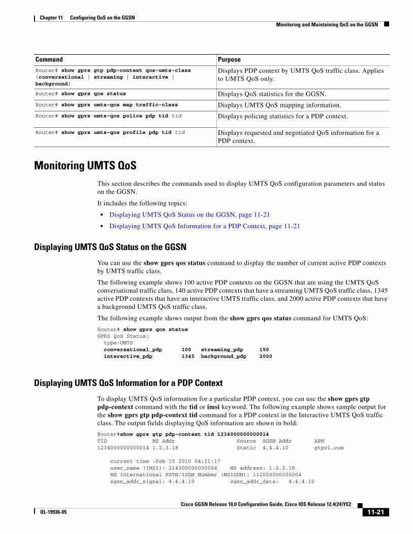
You can use the show gprs qos status command to display the number of current active PDP contexts by UMTS traffic class.
The following example shows 100 active PDP contexts on the GGSN that are using the UMTS QoS conversational traffic class, 140 active PDP contexts that have a streaming UMTS QoS traffic class, 1345 active PDP contexts that have an interactive UMTS traffic class, and 2000 active PDP contexts that have a background UMTS QoS traffic class.
The following example shows output from the show gprs qos status command for UMTS QoS:
Router# show gprs qos statusGPRS QoS Status: type:UMTS conversational_pdp 100 streaming_pdp 150 interactive_pdp 1345 background_pdp 2000
Displaying UMTS QoS Information for a PDP Context
To display UMTS QoS information for a particular PDP context, you can use the show gprs gtp pdp-context command with the tid or imsi keyword. The following example shows sample output for the show gprs gtp pdp-context tid command for a PDP context in the Interactive UMTS QoS traffic class. The output fields displaying QoS information are shown in bold:
Router#show gprs gtp pdp-context tid 1234000000000014TID MS Addr Source SGSN Addr APN1234000000000014 1.2.3.18 Static 4.4.4.10 gtpv1.com
current time :Feb 15 2010 04:11:17 user_name (IMSI): 214300000000004 MS address: 1.2.3.18 MS International PSTN/ISDN Number (MSISDN): 112000000000004 sgsn_addr_signal: 4.4.4.10 sgsn_addr_data: 4.4.4.10
Router# show gprs gtp pdp-context qos-umts-class {conversational | streaming | interactive | background}
Displays PDP context by UMTS QoS traffic class. Applies to UMTS QoS only.
Router# show gprs qos status Displays QoS statistics for the GGSN.
Router# show gprs umts-qos map traffic-class Displays UMTS QoS mapping information.
Router# show gprs umts-qos police pdp tid tid Displays policing statistics for a PDP context.
Router# show gprs umts-qos profile pdp tid tid Displays requested and negotiated QoS information for a PDP context.
Command Purpose
11-21Cisco GGSN Release 10.0 Configuration Guide, Cisco IOS Release 12.4(24)YE2
OL-19936-05

Chapter 11 Configuring QoS on the GGSN Configuration Examples
control teid local: 0x0210001F control teid remote: 0x00000041 data teid local: 0x02100020 data teid remote: 0x00000042 primary pdp: Y nsapi: 1 signal_sequence: 1 seq_tpdu_up: 0 seq_tpdu_down: 0 upstream_signal_flow: 0 upstream_data_flow: 0 downstream_signal_flow: 0 downstream_data_flow: 0 RAupdate_flow: 0 pdp_create_time: Feb 15 2010 04:07:59 last_access_time: Feb 15 2010 04:07:59 mnrgflag: 0 tos mask map: B8 session timeout: 86400 idle timeout: 720000
umts qos_req:0911016901010111050101 umts qos_neg:0911016901010111050101 QoS class:interactive QoS for charging: qos_req:000000 qos_neg:000000
rcv_pkt_count: 10026 rcv_byte_count: 1824732 send_pkt_count: 5380 send_byte_count: 4207160 cef_up_pkt: 0 cef_up_byte: 0 cef_down_pkt: 0 cef_down_byte: 0 cef_drop: 0 out-sequence pkt: 0 charging_id: 42194519 visitor: No roamer: Unknown charging characteristics: 1 charging characteristics received: 0 csg: csggroup1, address: 75.75.75.1 pdp reference count: 2 primary dns: 0.0.0.0 secondary dns: 0.0.0.0 primary nbns: 0.0.0.0 secondary nbns: 0.0.0.0 ntwk_init_pdp: 0 single pdp-session: Disabled
absolute session start time: NOT SET Accounting Session ID: 161616010283D657 Periodic accounting interval: NOT SET AAA Unique ID: 16 (0x10) Interim Update statistics: records sent 0, records failed 0 Direct Tunnel: Disabled Eggsn mode: 0x06 (QS: disabled, EGCDR: enabled, SVC-MESG: enabled) PDP internal flags: 7C0001 MCB internal flags: 0
Configuration ExamplesThis section includes the following examples:
• UMTS QoS Configuration Examples, page 11-23
• CAC Configuration Example, page 11-24
• Per-PDP Policing Configuration Example, page 11-26
11-22Cisco GGSN Release 10.0 Configuration Guide, Cisco IOS Release 12.4(24)YE2
OL-19936-05

Chapter 11 Configuring QoS on the GGSN Configuration Examples
UMTS QoS Configuration Examples
Supervisor Engine Configuration:Mls qos
Mls qos map dscp-cos 18 20 22 to 5Mls qos map dscp-cos 26 to 4Mls qos map dscp-cos 28,30 to 3
Access-list 101 permit ip any any dscp efAccess-list 102 permit ip any any dscp af21Access-list 103 permit ip any any dscp af31Access-list 103 permit ip any any dscp af32Access-list 103 permit ip any any dscp af33Access-list 104 permit ip any any
Class-map match-all conversational Match access-group 101Class-map match-all streaming
Match access-group 102Class-map match-all interactive
Match access-group 103Class-map match-all background
Match access-group 104
Mls qos aggregate-policer AGGREGATE-CONV <bit rate1> <normal-burst> <max-burst>Conform-action transmit exceed-action dropMls qos aggregate-policer AGGREGATE-STREAMING <bit rate2> <normal-burst> <max-burst> conform-action transmit exceed-action dropMls qos aggregate-policer AGGREGATE-INTERACTIVE <bit rate3> <normal-burst> <max-burst> conform-action transmit exceed-action dropMls qos aggregate-policer AGGREGATE-BACKGROUND <bit rate4> <normal-burst> <max-burst> conform-action transmit exceed-action drop
Policy-map Gi-incomingClass conversational
Police aggregate AGGREGATE-CONVClass streaming
Police aggregate AGGREGATE-STREAMINGClass interactive
Police aggregate AGGREGATE-INTERACTIVEClass background
Police aggregate AGGREGATE-BACKGROUND
Interface FastEthernet2/1Description “Gi interface”Mls qos trust dscpWrr-queue cos-map 1 1 3
Wrr-queue cos-map 1 2 4 Wrr-queue bandwidth 50 40 10
Service-policy input Gi-incoming
Interface FastEthernet2/2Description “Gn interface”Mls qos trust dscp
11-23Cisco GGSN Release 10.0 Configuration Guide, Cisco IOS Release 12.4(24)YE2
OL-19936-05

Chapter 11 Configuring QoS on the GGSN Configuration Examples
GGSN ConfigurationGprs qos map umts
Class-map match-all conversationalMatch ip dscp 46
Class-map match-any interactiveMatch ip dscp 26Match ip dscp 28Match ip dscp 30
Class-map match-any streamingMatch ip dscp 18Match ip dscp 20Match ip dscp 22
Class-map match-all signalingMatch ip dscp 40
Class-map match-any backgroundDescription default classMatch ip dscp 0
Policy-map sami-outputClass conversational
Priority percent 5Class streaming
Priority percent 15Class interactive
Bandwidth 20Class background
Bandwidth 20Class signaling
Bandwidth 15
interface Gigabitthernet 0/0 bandwidth 250000 service-policy output max-output
CAC Configuration ExampleThe following is a configuration example of CAC and QoS implemented on a GGSN running on the Cicso SAMI in a Cisco 7600 series router.
!Enable UMTS QoS Mapping
gprs qos map umts
!Create CAC Maximum QoS authorization policygprs qos cac-policy abc_qos_policy1
maximum pdp-context 1200 threshold 1000maximum traffic-class conversationalmbr traffic-class conversational 100 uplinkmbr traffic-class conversational 100 downlinkmbr traffic-class streaming 100 uplinkmbr traffic-class streaming 100 downlinkmbr traffic-class interactive 120 uplinkmbr traffic-class interactive 120 downlinkmbr traffic-class background 120 uplinkmbr traffic-class background 120 downlinkgbr traffic-class conversational 64 uplinkgbr traffic-class conversational 80 uplinkgbr traffic-class streaming 80 downlinkgbr traffic-class streaming 80 downlink
11-24Cisco GGSN Release 10.0 Configuration Guide, Cisco IOS Release 12.4(24)YE2
OL-19936-05
Chapter 11 Configuring QoS on the GGSN Configuration Examples
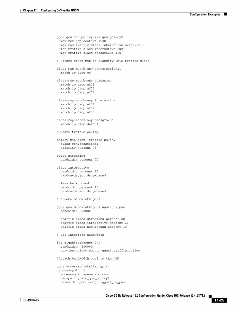
gprs qos cac-policy max_qos_policy2maximum pdp-context 1500maximum traffic-class interactive priority 1mbr traffic-class interactive 200mbr traffic-class background 150
! Create class-map to classify UMTS traffic class
class-map match-any conversationalmatch ip dscp ef
class-map match-any streamingmatch ip dscp af21match ip dscp af22match ip dscp af23
class-map match-any interactivematch ip dscp af31match ip dscp af32match ip dscp af33
class-map match-any backgroundmatch ip dscp default
!Create traffic policy
policy-map ggsn1_traffic_policyclass conversationalpriority percent 25
class streamingbandwidth percent 20
class interactivebandwidth percent 20random-detect dscp-based
class backgroundbandwidth percent 10random-detect dscp-based
! Create bandwidth pool
gprs qos bandwidth-pool ggsn1_bw_poolbandwidth 500000
traffic-class streaming percent 20traffic-class interactive percent 20traffic-class background percent 10
! Set interface bandwidth
int gigabitEthernet 0/0bandwidth 500000service-policy output ggsn1_traffic_policy
!Attach bandwidth pool to the APN
gprs access-point-list gprsaccess-point 1access-point-name abc.comcac-policy abc_qos_policy1bandwidth-pool output ggsn1_bw_pool
11-25Cisco GGSN Release 10.0 Configuration Guide, Cisco IOS Release 12.4(24)YE2
OL-19936-05
Chapter 11 Configuring QoS on the GGSN Configuration Examples
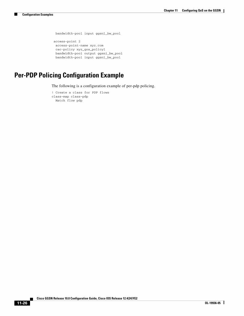
bandwidth-pool input ggsn1_bw_pool
access-point 2access-point-name xyz.comcac-policy xyz_qos_policy1bandwidth-pool output ggsn1_bw_poolbandwidth-pool input ggsn1_bw_pool
Per-PDP Policing Configuration ExampleThe following is a configuration example of per-pdp policing.
! Create a class for PDP flowsclass-map class-pdp
Match flow pdp
11-26Cisco GGSN Release 10.0 Configuration Guide, Cisco IOS Release 12.4(24)YE2
OL-19936-05

Chapter 11 Configuring QoS on the GGSN Configuration Examples
! Create a policy map and assign a class to the mappolicy-map policy-gprs
class class-pdp
! Configure traffic policingpolice rate pdp conform-action action exceed-action action violate-action action
! Attach a service policy to an APNgprs access-point-list gprsaccess-point 1service-policy in policy-gprs
11-27Cisco GGSN Release 10.0 Configuration Guide, Cisco IOS Release 12.4(24)YE2
OL-19936-05

Chapter 11 Configuring QoS on the GGSN Configuration Examples
11-28Cisco GGSN Release 10.0 Configuration Guide, Cisco IOS Release 12.4(24)YE2
OL-19936-05
Related Documents


![Configuring QoS on the GGSN · † Monitoring and Maintaining QoS on the GGSN, page 9-33 ... QoS (as defined in global system for mobile communication [GSM] standards 02.60, 03.60,](https://static.cupdf.com/doc/110x72/5f6af8f87cb9726380523adf/configuring-qos-on-the-ggsn-a-monitoring-and-maintaining-qos-on-the-ggsn-page.jpg)

