CHAPTER 47-1 Catalyst 4500 Series Switch, Cisco IOS Software Configuration Guide - Cisco IOS XE 3.9.xE and IOS 15.2(5)Ex 47 Configuring Private VLANs This chapter describes how to implement private VLANs (PVLANs) on Catalyst 4500 series switches. It also provides restrictions, procedures, and configuration examples. This chapter includes the following major sections: • About Private VLANs, page 47-1 • PVLAN Commands, page 47-10 • Configuring PVLANs, page 47-11 Note For complete syntax and usage information for the switch commands used in this chapter, see the Cisco IOS Command Reference Guides for the Catalyst 4500 Series Switch. If a command is not in the Cisco Catalyst 4500 Series Switch Command Reference , you can locate it in the Cisco IOS Master Command List, All Releases. About Private VLANs The private VLAN (PVLAN) feature addresses two problems that service providers face when using VLANs: • The switch supports up to 4094 active VLANs. If a service provider assigns one VLAN per customer, this limits the numbers of customers the service provider can support. • To enable IP routing, each VLAN is assigned a subnet address space or a block of addresses, which can result in wasting the unused IP addresses, and cause IP address management problems. To configure PVLANs, you need to understand the concepts in these sections: • Purpose of a PVLAN, page 47-2 • PVLAN Terminology, page 47-3 • PVLANs across Multiple Switches, page 47-5 • PVLAN Modes Over Gigabit Etherchannel, page 47-8 • Private-VLAN Interaction with Other Features, page 47-8

Welcome message from author
This document is posted to help you gain knowledge. Please leave a comment to let me know what you think about it! Share it to your friends and learn new things together.
Transcript
Catalyst 4500 Series Switch, Cisco IOS Software Configu
C H A P T E R 47
Configuring Private VLANsThis chapter describes how to implement private VLANs (PVLANs) on Catalyst 4500 series switches. It also provides restrictions, procedures, and configuration examples.
This chapter includes the following major sections:
• About Private VLANs, page 47-1
• PVLAN Commands, page 47-10
• Configuring PVLANs, page 47-11
Note For complete syntax and usage information for the switch commands used in this chapter, see theCisco IOS Command Reference Guides for the Catalyst 4500 Series Switch.
If a command is not in the Cisco Catalyst 4500 Series Switch Command Reference , you can locate it in the Cisco IOS Master Command List, All Releases.
About Private VLANsThe private VLAN (PVLAN) feature addresses two problems that service providers face when using VLANs:
• The switch supports up to 4094 active VLANs. If a service provider assigns one VLAN per customer, this limits the numbers of customers the service provider can support.
• To enable IP routing, each VLAN is assigned a subnet address space or a block of addresses, which can result in wasting the unused IP addresses, and cause IP address management problems.
To configure PVLANs, you need to understand the concepts in these sections:
• Purpose of a PVLAN, page 47-2
• PVLAN Terminology, page 47-3
• PVLANs across Multiple Switches, page 47-5
• PVLAN Modes Over Gigabit Etherchannel, page 47-8
• Private-VLAN Interaction with Other Features, page 47-8
47-1ration Guide - Cisco IOS XE 3.9.xE and IOS 15.2(5)Ex
Chapter 47 Configuring Private VLANsAbout Private VLANs
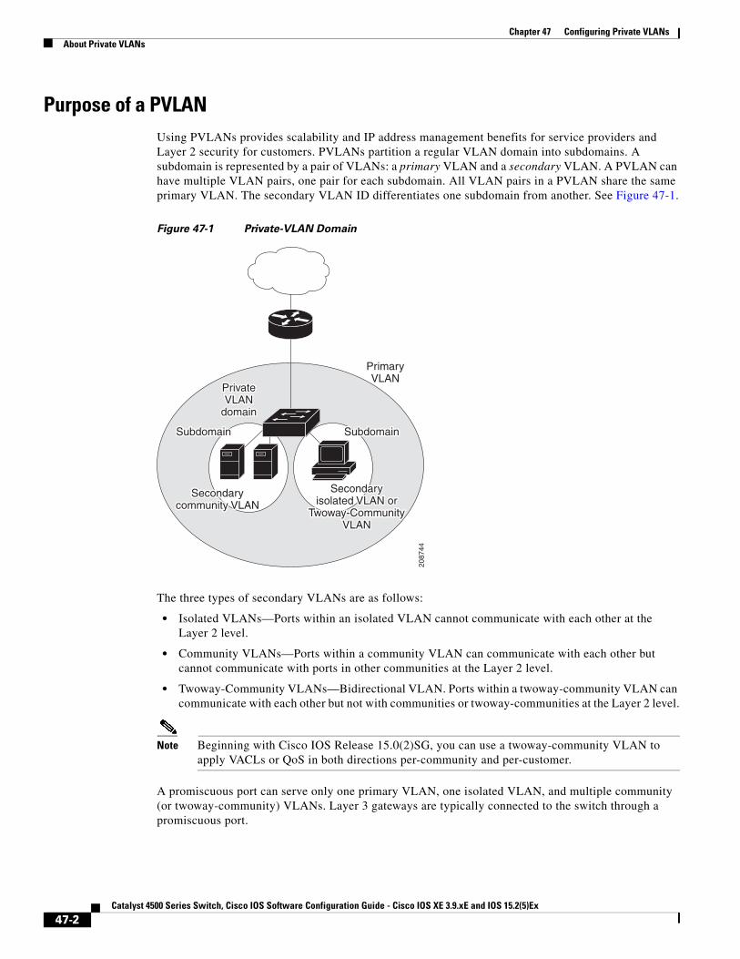
Purpose of a PVLANUsing PVLANs provides scalability and IP address management benefits for service providers and Layer 2 security for customers. PVLANs partition a regular VLAN domain into subdomains. A subdomain is represented by a pair of VLANs: a primary VLAN and a secondary VLAN. A PVLAN can have multiple VLAN pairs, one pair for each subdomain. All VLAN pairs in a PVLAN share the same primary VLAN. The secondary VLAN ID differentiates one subdomain from another. See Figure 47-1.
Figure 47-1 Private-VLAN Domain
The three types of secondary VLANs are as follows:
• Isolated VLANs—Ports within an isolated VLAN cannot communicate with each other at the Layer 2 level.
• Community VLANs—Ports within a community VLAN can communicate with each other but cannot communicate with ports in other communities at the Layer 2 level.
• Twoway-Community VLANs—Bidirectional VLAN. Ports within a twoway-community VLAN can communicate with each other but not with communities or twoway-communities at the Layer 2 level.
Note Beginning with Cisco IOS Release 15.0(2)SG, you can use a twoway-community VLAN to apply VACLs or QoS in both directions per-community and per-customer.
A promiscuous port can serve only one primary VLAN, one isolated VLAN, and multiple community (or twoway-community) VLANs. Layer 3 gateways are typically connected to the switch through a promiscuous port.
2087
44
PrivatePrivateVLANVLAN
domaindomain
PrivateVLAN
domain
PrimaryVLAN
SubdomainSubdomain
Secondarycommunity VLAN
SubdomainSubdomain
Secondarycommunity VLAN
Secondaryisolated VLAN or
Twoway-CommunityVLAN
Secondaryisolated VLAN or
Twoway-CommunityVLAN
47-2Catalyst 4500 Series Switch, Cisco IOS Software Configuration Guide - Cisco IOS XE 3.9.xE and IOS 15.2(5)Ex

Chapter 47 Configuring Private VLANsAbout Private VLANs
In a switched environment, you can assign an individual PVLAN and associated IP subnet to each individual or common group of end stations. The end stations need to communicate only with a default gateway to communicate outside the PVLAN.
You can use PVLANs to control access to end stations in these ways:
• Configure selected interfaces connected to end stations as isolated ports to prevent any communication at Layer 2. For example, if the end stations are servers, this configuration prevents Layer 2 communication between the servers.
• Configure interfaces connected to default gateways and selected end stations (such as, backup servers) as promiscuous ports to allow all end stations access to a default gateway.
• Reduce VLAN and IP subnet consumption; you can prevent traffic between end stations even though they are in the same VLAN and IP subnet.
With a promiscuous port, you can connect a wide range of devices as access points to a PVLAN. For example, you can connect a promiscuous port to the server port of a LocalDirector to connect an isolated VLAN or a number of community (or twoway-community) VLANs to the server. LocalDirector can load balance the servers present in the isolated, community, or twoway-community VLANs, or you can use a promiscuous port to monitor or back up all the PVLAN servers from an administration workstation.
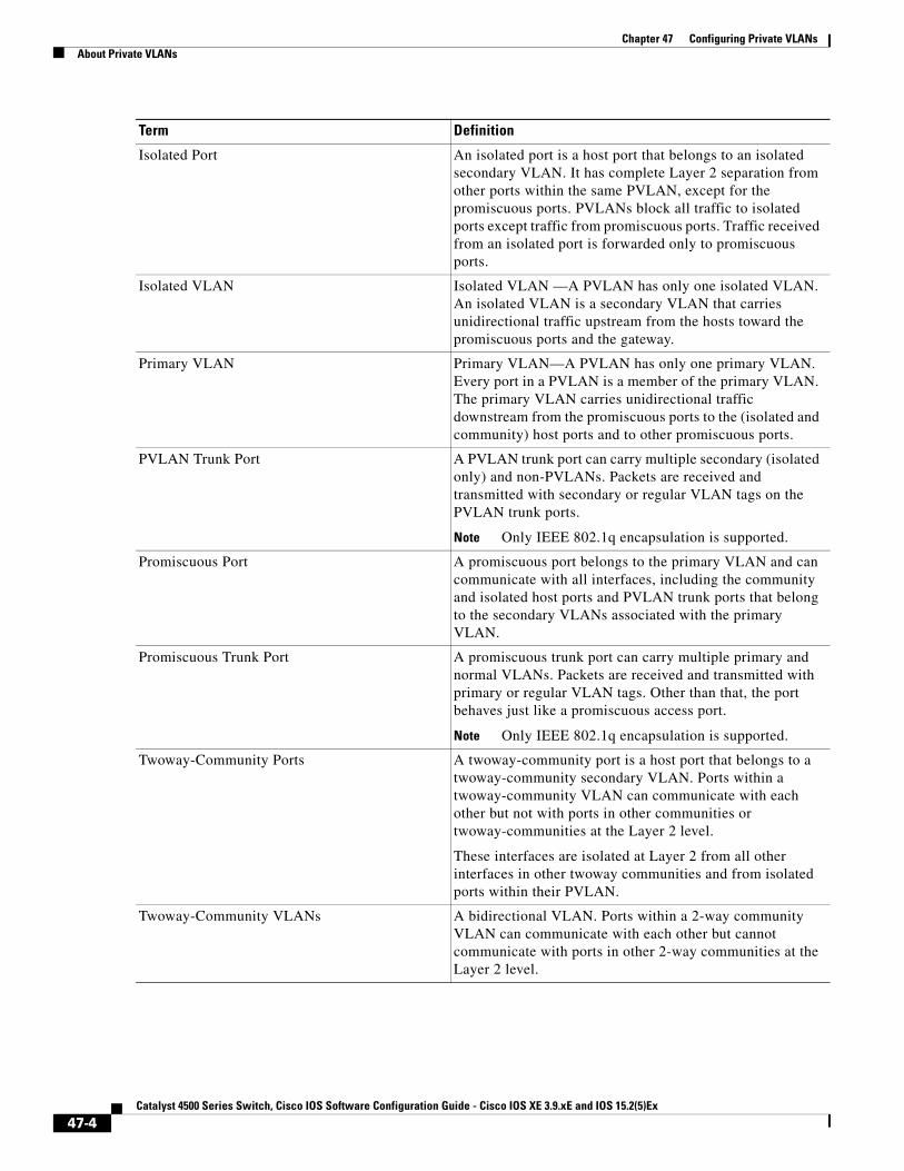
PVLAN TerminologyThe following table defines the key terms used in this chapter:
Term Definition
PVLANs PVLANs are sets of VLAN pairs that share a common primary identifier and provide a mechanism for achieving layer-2 separation between ports while sharing a single layer-3 router port and IP subnet.
Secondary VLAN A type of VLAN used to implement PVLANs. Secondary VLANs are associated with a primary VLAN, and are used to carry traffic from hosts to other allowed hosts or to routers.
Community Port A community port is a host port that belongs to a community secondary VLAN. Community ports communicate with other ports in the same community VLAN and with promiscuous ports. These interfaces are isolated at Layer 2 from all other interfaces in other communities and from isolated ports within their PVLAN.
Community VLAN Community VLAN—A community VLAN is a secondary VLAN that carries upstream traffic from the community ports to the promiscuous port gateways and to other host ports in the same community. You can configure multiple community VLANs in a PVLAN.
47-3Catalyst 4500 Series Switch, Cisco IOS Software Configuration Guide - Cisco IOS XE 3.9.xE and IOS 15.2(5)Ex
Chapter 47 Configuring Private VLANsAbout Private VLANs
Isolated Port An isolated port is a host port that belongs to an isolated secondary VLAN. It has complete Layer 2 separation from other ports within the same PVLAN, except for the promiscuous ports. PVLANs block all traffic to isolated ports except traffic from promiscuous ports. Traffic received from an isolated port is forwarded only to promiscuous ports.
Isolated VLAN Isolated VLAN —A PVLAN has only one isolated VLAN. An isolated VLAN is a secondary VLAN that carries unidirectional traffic upstream from the hosts toward the promiscuous ports and the gateway.
Primary VLAN Primary VLAN—A PVLAN has only one primary VLAN. Every port in a PVLAN is a member of the primary VLAN. The primary VLAN carries unidirectional traffic downstream from the promiscuous ports to the (isolated and community) host ports and to other promiscuous ports.
PVLAN Trunk Port A PVLAN trunk port can carry multiple secondary (isolated only) and non-PVLANs. Packets are received and transmitted with secondary or regular VLAN tags on the PVLAN trunk ports.
Note Only IEEE 802.1q encapsulation is supported.
Promiscuous Port A promiscuous port belongs to the primary VLAN and can communicate with all interfaces, including the community and isolated host ports and PVLAN trunk ports that belong to the secondary VLANs associated with the primary VLAN.
Promiscuous Trunk Port A promiscuous trunk port can carry multiple primary and normal VLANs. Packets are received and transmitted with primary or regular VLAN tags. Other than that, the port behaves just like a promiscuous access port.
Note Only IEEE 802.1q encapsulation is supported.
Twoway-Community Ports A twoway-community port is a host port that belongs to a twoway-community secondary VLAN. Ports within a twoway-community VLAN can communicate with each other but not with ports in other communities or twoway-communities at the Layer 2 level.
These interfaces are isolated at Layer 2 from all other interfaces in other twoway communities and from isolated ports within their PVLAN.
Twoway-Community VLANs A bidirectional VLAN. Ports within a 2-way community VLAN can communicate with each other but cannot communicate with ports in other 2-way communities at the Layer 2 level.
Term Definition
47-4Catalyst 4500 Series Switch, Cisco IOS Software Configuration Guide - Cisco IOS XE 3.9.xE and IOS 15.2(5)Ex
Chapter 47 Configuring Private VLANsAbout Private VLANs
PVLANs across Multiple SwitchesThis section discusses the following topics:
• Standard Trunk Ports, page 47-5
• Isolated PVLAN Trunk Ports, page 47-6
• Promiscuous PVLAN Trunk Ports, page 47-7
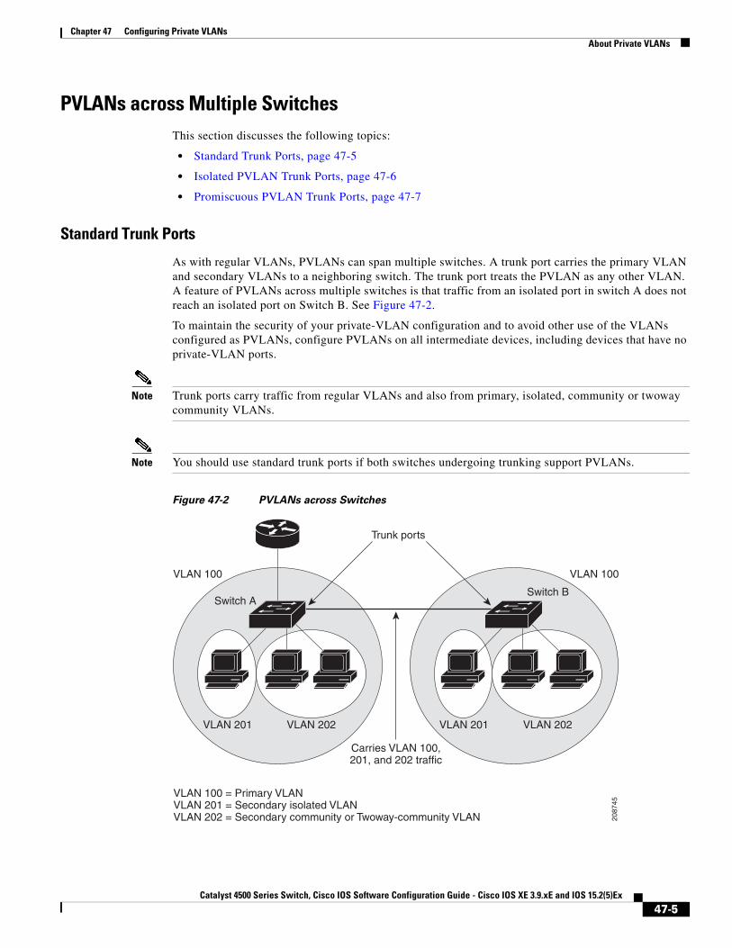
Standard Trunk Ports
As with regular VLANs, PVLANs can span multiple switches. A trunk port carries the primary VLAN and secondary VLANs to a neighboring switch. The trunk port treats the PVLAN as any other VLAN. A feature of PVLANs across multiple switches is that traffic from an isolated port in switch A does not reach an isolated port on Switch B. See Figure 47-2.
To maintain the security of your private-VLAN configuration and to avoid other use of the VLANs configured as PVLANs, configure PVLANs on all intermediate devices, including devices that have no private-VLAN ports.
Note Trunk ports carry traffic from regular VLANs and also from primary, isolated, community or twoway community VLANs.
Note You should use standard trunk ports if both switches undergoing trunking support PVLANs.
Figure 47-2 PVLANs across Switches
2087
45
VLAN 100
VLAN 201 VLAN 202
Switch B
VLAN 100
VLAN 100 = Primary VLANVLAN 201 = Secondary isolated VLANVLAN 202 = Secondary community or Twoway-community VLAN
VLAN 201
Carries VLAN 100,201, and 202 traffic
Trunk ports
VLAN 202
Switch A
47-5Catalyst 4500 Series Switch, Cisco IOS Software Configuration Guide - Cisco IOS XE 3.9.xE and IOS 15.2(5)Ex

Chapter 47 Configuring Private VLANsAbout Private VLANs
Because VTP does not support PVLANs, you must manually configure PVLANs on all switches in the Layer 2 network. If you do not configure the primary and secondary VLAN association in some switches in the network, the Layer 2 databases in these switches are not merged. This can result in unnecessary flooding of private-VLAN traffic on those switches.
Note PVLANs are supported in VTP v3 under server mode.
Isolated PVLAN Trunk Ports
You would use a isolated PVLAN trunk ports when you would anticipate using PVLAN isolated host ports to carry multiple VLANs, either normal VLANs or for multiple PVLAN domains. This makes it useful for connecting a downstream switch that does not support PVLANs such as Catalyst 2950.
Figure 47-3 Isolated PVLAN Trunk Ports
In this illustration, a Catalyst 4500 switch is being used to connect a downstream switch that does not support PVLANs.
Traffic being sent in the downstream direction towards host1 from the router is received by the Catalyst 4500 series switch on the promiscuous port and in the primary VLAN (VLAN 10). The packets are then switched out of the isolated PVLAN trunk. Rather that being tagged with the primary VLAN (VLAN 10), they are transmitted with the isolated VLAN’s tag (VLAN 11). In this way, when the packets arrive on the non-PVLAN switch, they can be bridged to the destination hosts’ access port.
Catalyst 7200router
Catalyst4500 switch
Non-PVLANswitch (2950)
Primary VLAN = VLAN10Isolated VLAN = VLAN11
Isolated PVLANtrunk port
Access portson VLAN11
Isolated port
2042
02
47-6Catalyst 4500 Series Switch, Cisco IOS Software Configuration Guide - Cisco IOS XE 3.9.xE and IOS 15.2(5)Ex
Chapter 47 Configuring Private VLANsAbout Private VLANs
Traffic in the upstream direction is sent by host1 to the non-PVLAN switch, arriving in VLAN 11. The packets are then transmitted to the switch tagged with that VLAN’s tag (VLAN 11) over the trunk port. On the switch, VLAN 11 is configured as the isolated VLAN, and the traffic is forwarded as if it came from an isolated host port.
Note When an isolated trunk is used in this way, Catalyst 4500 series switch provides isolation between the isolated trunk and directly connected hosts (such as host3) but not between hosts connected to the non-PVLAN switch (such as host1 and host2). The non-PVLAN switch must provide isolation between these hosts, using a feature such as protected ports on a Catalyst 2950.
For details on protected ports, see the URL:
http://www.cisco.com/en/US/docs/switches/lan/catalyst2950/software/release/12.1_22_ea11x/configuration/guide/swtrafc.html#wp1158863
Promiscuous PVLAN Trunk Ports
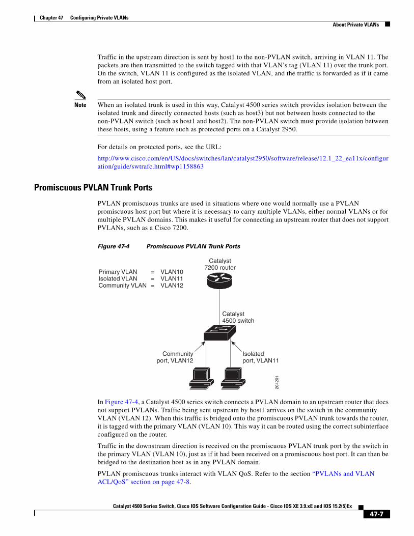
PVLAN promiscuous trunks are used in situations where one would normally use a PVLAN promiscuous host port but where it is necessary to carry multiple VLANs, either normal VLANs or for multiple PVLAN domains. This makes it useful for connecting an upstream router that does not support PVLANs, such as a Cisco 7200.
Figure 47-4 Promiscuous PVLAN Trunk Ports
In Figure 47-4, a Catalyst 4500 series switch connects a PVLAN domain to an upstream router that does not support PVLANs. Traffic being sent upstream by host1 arrives on the switch in the community VLAN (VLAN 12). When this traffic is bridged onto the promiscuous PVLAN trunk towards the router, it is tagged with the primary VLAN (VLAN 10). This way it can be routed using the correct subinterface configured on the router.
Traffic in the downstream direction is received on the promiscuous PVLAN trunk port by the switch in the primary VLAN (VLAN 10), just as if it had been received on a promiscuous host port. It can then be bridged to the destination host as in any PVLAN domain.
PVLAN promiscuous trunks interact with VLAN QoS. Refer to the section “PVLANs and VLAN ACL/QoS” section on page 47-8.
Catalyst7200 router
Catalyst4500 switch
Primary VLAN = VLAN10Isolated VLAN = VLAN11Community VLAN = VLAN12
Isolatedport, VLAN11
Communityport, VLAN12
2042
01
47-7Catalyst 4500 Series Switch, Cisco IOS Software Configuration Guide - Cisco IOS XE 3.9.xE and IOS 15.2(5)Ex

Chapter 47 Configuring Private VLANsAbout Private VLANs
PVLAN Modes Over Gigabit EtherchannelBeginning with Cisco IOS Release 15.0(2)SG you can configure PVLAN modes over Etherchannel. These new modes are:
• Host mode - Isolated, Community and 2-way community
• Promiscuous mode
• Secondary Isolated trunks
• Promiscuous trunks
The process of bundling ports has not changed. PVLAN modes are added to already existing modes such as access, trunk, routed, tunneled etc.
Feature interactions include:
• A primary VLAN can be associated with multiple community and twoway-community VLANs, but only one isolated VLAN.
• An isolated or community VLAN or 2-way community VLAN can be associated with only one primary VLAN.
• If you delete a VLAN used in a PVLAN configuration, the PVLAN ports associated with the VLAN become inactive.
• The default native VLAN for promiscuous trunk port is VLAN 1 (management VLAN). All untagged packets are forwarded in the native VLAN. Either the primary VLANs or a regular VLAN can be configured as the native VLAN.
• No default native VLAN set exists on an isolated secondary trunks. All untagged packets are dropped, if no native VLAN is configured.
• Community and twoway-community VLANs cannot be propagated or carried over PVLAN trunks.
• For IGMP Snooping, IGMP reports are learned on the primary VLAN and the platform decides if packet must be forwarded in the primary or secondary VLANs.
For details on configuring PVLANs over EtherChannel, Refer to the section “Configuring PVLAN over EtherChannel” section on page 47-24.
Private-VLAN Interaction with Other FeaturesPVLANs have specific interaction with some other features, described in these sections:
• PVLANs and VLAN ACL/QoS, page 47-8
• PVLANs and Unicast, Broadcast, and Multicast Traffic, page 47-9
• PVLANs and SVIs, page 47-10
• Per-Virtual Port Error-Disable on PVLANs, page 47-10
For details, see the section “PVLAN Configuration Guidelines and Restrictions” on page 12.
PVLANs and VLAN ACL/QoS
PVLAN ports use primary and secondary VLANs, as follows:
• A packet received on a PVLAN host port belongs to the secondary VLAN.
47-8Catalyst 4500 Series Switch, Cisco IOS Software Configuration Guide - Cisco IOS XE 3.9.xE and IOS 15.2(5)Ex

Chapter 47 Configuring Private VLANsAbout Private VLANs
• A packet received on a PVLAN trunk port belongs to the secondary VLAN if the packet is tagged with a secondary VLAN or if the packet is untagged and the native VLAN on the port is a secondary VLAN.
A packet received on a PVLAN host or trunk port and assigned to a secondary VLAN is bridged on the secondary VLAN. Because of this bridging, the secondary VLAN ACL as well as the secondary VLAN QoS (on input direction) apply.
When a packet is transmitted out of a PVLAN host or trunk port, the packet logically belongs to the primary VLAN. This relationship applies even though the packet may be transmitted with the secondary VLAN tagging for PVLAN trunk ports. In this situation, the primary VLAN ACL and the primary VLAN QoS on output apply to the packet.
• Similarly, a packet received on a PVLAN promiscuous access port belongs to primary VLAN.
• A packet received on a PVLAN promiscuous trunk port could belong to the primary VLAN or normal VLAN depending on incoming VLAN.
For traffic flowing in normal VLAN on promiscuous trunk ports, normal VLAN ACL and QoS policies apply. For traffic flowing in a PVLAN domain, a packet received on a promiscuous port is bridged in primary VLAN. The primary VLAN ACL and QoS policies apply on input.
For egress traffic on twoway-community host port, the secondary VLAN ACL and secondary VLAN QoS apply to egress unicast routed traffic stemming from the integrated router port.
When a packet is transmitted out of a promiscuous trunk port, the packet could logically belong to secondary VLAN if received from a secondary port, or in primary VLAN if bridged from another promiscuous port. Because we cannot differentiate between both packets, all VLAN QoS policies are ignored on packets egressing promiscuous trunk ports.
PVLANs and Unicast, Broadcast, and Multicast Traffic
In regular VLANs, devices in the same VLAN can communicate with each other at the Layer 2 level, but devices connected to interfaces in different VLANs must communicate at the Layer 3 level. In PVLANs, the promiscuous ports are members of the primary VLAN, while the host ports belong to secondary VLANs. Because the secondary VLAN is associated to the primary VLAN, members of the these VLANs can communicate with each other at the Layer 2 level.
In a regular VLAN, broadcasts are forwarded to all ports in that VLAN. PVLAN broadcast forwarding depends on the port sending the broadcast:
• An isolated port sends a broadcast only to the promiscuous ports or trunk ports.
• A community port sends a broadcast to all promiscuous ports, trunk ports, and ports in the same community VLAN.
• A promiscuous port sends a broadcast to all ports in the PVLAN (other promiscuous ports, trunk ports, isolated ports, and community ports).
Multicast traffic is routed or bridged across private-VLAN boundaries and within a single community VLAN. Multicast traffic is not forwarded between ports in the same isolated VLAN or between ports in different secondary VLANs.
Transmitting Multicast traffic through secondary private VLAN where the multicast source is located is not supported. This might result in software switching of the packets and thereby causing significantly lower forwarding rate and packet loss.
47-9Catalyst 4500 Series Switch, Cisco IOS Software Configuration Guide - Cisco IOS XE 3.9.xE and IOS 15.2(5)Ex

Chapter 47 Configuring Private VLANsPVLAN Commands
PVLANs and SVIs
In a Layer 3 switch, a switch virtual interface (SVI) represents the Layer 3 interface of a VLAN. Layer 3 devices communicate with a PVLAN only using the primary VLAN and not through secondary VLANs. Configure Layer 3 VLAN interfaces (SVIs) only for primary VLANs. You cannot configure Layer 3 VLAN interfaces for secondary VLANs. SVIs for secondary VLANs are inactive while the VLAN is configured as a secondary VLAN.
• If you try to configure a VLAN with an active SVI as a secondary VLAN, the configuration is not allowed until you disable the SVI.
• If you try to create an SVI on a VLAN that is configured as a secondary VLAN and the secondary VLAN is already mapped at Layer 3, the SVI is not created, and an error is returned. If the SVI is not mapped at Layer 3, the SVI is created, but it is automatically shut down.
When the primary VLAN is associated with and mapped to the secondary VLAN, any configuration on the primary VLAN is propagated to the secondary VLAN SVIs. For example, if you assign an IP subnet to the primary VLAN SVI, this subnet is the IP subnet address of the entire PVLAN.
Per-Virtual Port Error-Disable on PVLANs
For PVLANs, per-virtual port error-disable behavior is defined as follows:
• On a PVLAN promiscuous or promiscuous trunk ports, if a violation occurs on the primary VLAN, it is error-disabled.
• On a PVLAN host or trunk port, if a violation occurs on the secondary VLAN, the associated primary VLAN is error-disabled.
• On a standard trunk port that carries both primary and secondary VLANs, if a violation occurs on the primary VLAN, this VLAN and all its associated secondary VLANs are error-disabled. If a violation occurs on a secondary VLAN, the associated primary VLAN and all its associated secondary VLANs are error-disabled.
PVLAN CommandsThis table lists the commands most commonly used with PVLANs.
Command Purpose Location
private-vlan {community | twoway-community | isolated | primary}
Configures a VLAN as a PVLAN. Configuring a VLAN as a PVLAN, page 47-15
private-vlan association {secondary_vlan_list | add secondary_vlan_list | remove secondary_vlan_list}
Associates the secondary VLAN with the primary VLAN.
The list can contain only one isolated VLAN ID; it can also contain multiple community VLAN IDs.
Associating a Secondary VLAN with a Primary VLAN, page 47-16
show vlan private-vlan [type] Verifies the configuration. Configuring a VLAN as a PVLAN, page 47-15
Associating a Secondary VLAN with a Primary VLAN, page 47-16
47-10Catalyst 4500 Series Switch, Cisco IOS Software Configuration Guide - Cisco IOS XE 3.9.xE and IOS 15.2(5)Ex
Chapter 47 Configuring Private VLANsConfiguring PVLANs
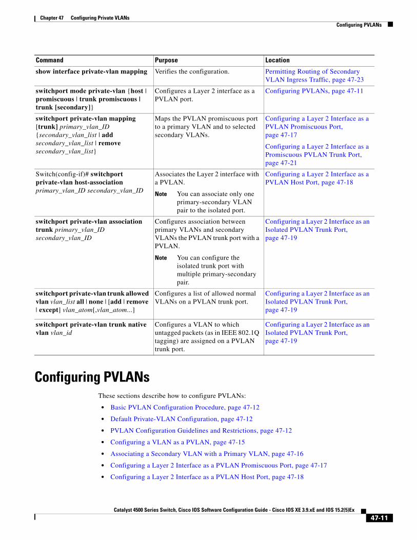
Configuring PVLANsThese sections describe how to configure PVLANs:
• Basic PVLAN Configuration Procedure, page 47-12
• Default Private-VLAN Configuration, page 47-12
• PVLAN Configuration Guidelines and Restrictions, page 47-12
• Configuring a VLAN as a PVLAN, page 47-15
• Associating a Secondary VLAN with a Primary VLAN, page 47-16
• Configuring a Layer 2 Interface as a PVLAN Promiscuous Port, page 47-17
• Configuring a Layer 2 Interface as a PVLAN Host Port, page 47-18
show interface private-vlan mapping Verifies the configuration. Permitting Routing of Secondary VLAN Ingress Traffic, page 47-23
switchport mode private-vlan {host | promiscuous | trunk promiscuous | trunk [secondary]}
Configures a Layer 2 interface as a PVLAN port.
Configuring PVLANs, page 47-11
switchport private-vlan mapping [trunk] primary_vlan_ID {secondary_vlan_list | add secondary_vlan_list | remove secondary_vlan_list}
Maps the PVLAN promiscuous port to a primary VLAN and to selected secondary VLANs.
Configuring a Layer 2 Interface as a PVLAN Promiscuous Port, page 47-17
Configuring a Layer 2 Interface as a Promiscuous PVLAN Trunk Port, page 47-21
Switch(config-if)# switchport private-vlan host-association primary_vlan_ID secondary_vlan_ID
Associates the Layer 2 interface with a PVLAN.
Note You can associate only one primary-secondary VLAN pair to the isolated port.
Configuring a Layer 2 Interface as a PVLAN Host Port, page 47-18
switchport private-vlan association trunk primary_vlan_ID secondary_vlan_ID
Configures association between primary VLANs and secondary VLANs the PVLAN trunk port with a PVLAN.
Note You can configure the isolated trunk port with multiple primary-secondary pair.
Configuring a Layer 2 Interface as an Isolated PVLAN Trunk Port, page 47-19
switchport private-vlan trunk allowed vlan vlan_list all | none | [add | remove | except] vlan_atom[,vlan_atom...]
Configures a list of allowed normal VLANs on a PVLAN trunk port.
Configuring a Layer 2 Interface as an Isolated PVLAN Trunk Port, page 47-19
switchport private-vlan trunk native vlan vlan_id
Configures a VLAN to which untagged packets (as in IEEE 802.1Q tagging) are assigned on a PVLAN trunk port.
Configuring a Layer 2 Interface as an Isolated PVLAN Trunk Port, page 47-19
Command Purpose Location
47-11Catalyst 4500 Series Switch, Cisco IOS Software Configuration Guide - Cisco IOS XE 3.9.xE and IOS 15.2(5)Ex

Chapter 47 Configuring Private VLANsConfiguring PVLANs
• Configuring a Layer 2 Interface as an Isolated PVLAN Trunk Port, page 47-19
• Configuring a Layer 2 Interface as a Promiscuous PVLAN Trunk Port, page 47-21
• Permitting Routing of Secondary VLAN Ingress Traffic, page 47-23
• Configuring PVLAN over EtherChannel, page 47-24
Basic PVLAN Configuration ProcedureTo configure a PVLAN, follow these basic steps:
Step 1 Set VTP mode to transparent. See the “VLAN Trunking Protocol” section on page 17-7.
Step 2 Create the secondary VLANs. See the “Configuring a VLAN as a PVLAN” section on page 47-15.
Step 3 Create the primary VLAN. See the “Configuring a VLAN as a PVLAN” section on page 47-15.
Step 4 Associate the secondary VLAN to the primary VLAN. See the “Associating a Secondary VLAN with a Primary VLAN” section on page 47-16.
Note Only one isolated VLAN can be mapped to a primary VLAN, but more than one community (or twoway-community) VLAN can be mapped to a primary VLAN.
Step 5 Configure an interface as an isolated or community host or trunk port. See the “Configuring a Layer 2 Interface as a PVLAN Host Port” section on page 47-18 and “Configuring a Layer 2 Interface as an Isolated PVLAN Trunk Port” section on page 47-19.
Step 6 Associate the isolated port or community port to the primary-secondary VLAN pair. See the “Associating a Secondary VLAN with a Primary VLAN” section on page 47-16.
Step 7 Configure an interface as a promiscuous port. See the “Configuring a Layer 2 Interface as a PVLAN Promiscuous Port” section on page 47-17.
Step 8 Map the promiscuous port to the primary-secondary VLAN pair. See the “Configuring a Layer 2 Interface as a PVLAN Promiscuous Port” section on page 47-17.
Step 9 If you plan to use inter-VLAN routing, configure the primary SVI, and map secondary VLANs to the primary. See the “Permitting Routing of Secondary VLAN Ingress Traffic” section on page 47-23.
Step 10 Verify private-VLAN configuration. See the “Switch#” section on page 47-24.
Default Private-VLAN ConfigurationNo PVLANs are configured.
PVLAN Configuration Guidelines and RestrictionsWhen using (or configuring) PVLANs, consider these guidelines and restrictions:
• To configure a PVLAN correctly, enable VTP in transparent mode in VTP version 1 and VTP version 2. (VTP version 3 enables you to create it in server mode).
You cannot change the VTP mode to client or server for PVLANs.
47-12Catalyst 4500 Series Switch, Cisco IOS Software Configuration Guide - Cisco IOS XE 3.9.xE and IOS 15.2(5)Ex

Chapter 47 Configuring Private VLANsConfiguring PVLANs
• Do not include VLAN 1 or VLANs 1002 through 1005 in PVLANs.
• Use only PVLAN commands to assign ports to primary, isolated, community VLANs, or twoway-community VLANs.
Layer 2 interfaces on primary, isolated, community VLANs, or twoway-community VLANs are inactive in PVLANs. Layer 2 trunk interfaces remain in the STP forwarding state.
• You cannot configure Layer 3 VLAN interfaces for secondary VLANs.
Layer 3 VLAN interfaces for isolated and community (secondary) VLANs are inactive while the VLAN is configured as an isolated or community VLAN.
• Do not apply dynamic access control entries (ACEs) to primary VLANs.
Cisco IOS dynamic ACL configuration applied to a primary VLAN is inactive while the VLAN is part of the PVLAN configuration.
• To prevent spanning tree loops due to misconfigurations, enable PortFast on the PVLAN trunk ports with the spanning-tree portfast trunk command.
• Any VLAN ACL configured on a secondary VLAN is effective in the input direction, and any VLAN ACL configured on the primary VLAN associated with the secondary VLAN is effective in the output direction. Exception case is given below.
• On twoway-community host ports, secondary VLAN ACL and QoS are applied on egress unicast routed traffic stemming from the integrated router port
• You can stop Layer 3 switching on an isolated or community VLAN by deleting the mapping of that VLAN with its primary VLAN.
• PVLAN ports can be on different network devices as long as the devices are trunk-connected and the primary and secondary VLANs remain associated with the trunk
• Isolated ports on two different devices cannot communicate with each other, but community VLAN ports can.
• PVLANs support the following SPAN features:
– You can configure a PVLAN port as a SPAN source port.
– To monitor egress or ingress traffic separately, you can use VLAN-based SPAN (VSPAN) on primary, isolated, community VLANs, twoway-community VLANs, or use SPAN on only one VLAN.
For more information about SPAN, see Chapter 66, “Configuring SPAN and RSPAN.”
• A primary VLAN can be associated with multiple community VLANs, or twoway-community VLANs, but only one isolated VLAN.
• An isolated or community VLAN can be associated with only one primary VLAN.
• If you delete a VLAN used in a PVLAN configuration, the PVLAN ports associated with the VLAN become inactive.
• VTP does not support PVLANs. You must configure PVLANs on each device in which you plan to use PVLAN ports.
• To maintain the security of your PVLAN configuration and avoid other use of VLANs configured as PVLANs, configure PVLANs on all intermediate devices, even if the devices have no PVLAN ports.
• Prune the PVLANs from trunks on devices that carry no traffic in the PVLANs.
47-13Catalyst 4500 Series Switch, Cisco IOS Software Configuration Guide - Cisco IOS XE 3.9.xE and IOS 15.2(5)Ex
Chapter 47 Configuring Private VLANsConfiguring PVLANs
• With port ACLS functionality available, you can apply Cisco IOS ACLS to secondary VLAN ports and Cisco IOS ACLS to PVLANS (VACLs). For more information on VACLs, see Chapter 62, “Configuring Network Security with ACLs.”
• You can apply different quality of service (QoS) configurations to primary, isolated, community VLANs, and twoway-community VLANs. See Chapter 44, “Configuring Quality of Service.” Cisco IOS ACLs applied to the Layer 3 VLAN interface of a primary VLAN automatically apply to the associated isolated, community VLANs, and twoway-community VLANs.
• On a PVLAN trunk port a secondary VLAN ACL is applied on ingress traffic and a primary VLAN ACL is applied on egress traffic.
• On a promiscuous port the primary VLAN ACL is applied on ingress traffic.
• Both PVLAN secondary and promiscuous trunk ports support only IEEE 802.1q encapsulation.
• Community VLANs cannot be propagated or carried over PVLAN trunks.
• ARP entries learned on Layer 3 PVLAN interfaces are termed “sticky” ARP entries (we recommend that you display and verify PVLAN interface ARP entries).
• For security reasons, PVLAN port sticky ARP entries do not age out. Connecting a device with a different MAC address but with the same IP address generates an error message and the ARP entry is not created.
• Because PVLAN port sticky ARP entries do not age out, you must manually remove the entries if you change the MAC address. To overwrite a sticky ARP entry, first delete the entry with the no arp command, then overwrite the entry with the arp command.
• In a DHCP environment, if you shut down your PC, it is not possible to give your IP address to someone else. To solve this problem, the Catalyst 4500 series switch supports the no ip sticky-arp command. This command promotes IP address overwriting and reuse in a DHCP environment.
• Normal VLANs can be carried on a promiscuous or isolated trunk port.
• The default native VLAN for promiscuous trunk port is VLAN 1, the management VLAN. All untagged packets are forwarded in the native VLAN. Either the primary VLANs or a regular VLAN can be configured as native VLAN.
• Promiscuous trunks cannot be configured to carry secondary VLANs. If a secondary VLAN is specified in the allowed VLAN list, the configuration is accepted but the port is not operational/forwarding in the secondary VLAN. This includes even those VLANs that are of secondary but not associated with any primary VLAN on given port.
• On a promiscuous trunk port, the primary VLAN ACL and QoS are applied on ingress traffic coming in primary VLANs.
• On a promiscuous trunk port, no VLAN ACL or QoS is applied to the egress traffic. it is because for upstream direction, traffic in PVLAN logically flows in the secondary VLAN. Due to VLAN translation in hardware, information about received secondary VLANs has been lost. No policies are applied. This restriction also applies to traffic bridged from other ports in the same primary VLANs.
• Do not configure port security on PVLAN promiscuous trunk port and vice versa.
If port security is enabled on a promiscuous trunk port, that port may behave in an unpredictable manner because this functionality is not supported.
• Do not configure IEEE 802.1X on a PVLAN promiscuous trunk port.
Note Community or twoway-community PVLAN trunk ports are not supported.
47-14Catalyst 4500 Series Switch, Cisco IOS Software Configuration Guide - Cisco IOS XE 3.9.xE and IOS 15.2(5)Ex
Chapter 47 Configuring Private VLANsConfiguring PVLANs
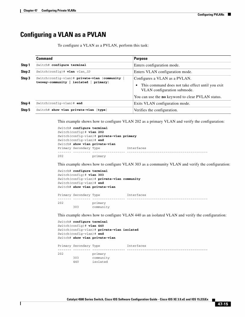
Configuring a VLAN as a PVLANTo configure a VLAN as a PVLAN, perform this task:
This example shows how to configure VLAN 202 as a primary VLAN and verify the configuration:
Switch# configure terminal Switch(config)# vlan 202 Switch(config-vlan)# private-vlan primary Switch(config-vlan)# end Switch# show vlan private-vlanPrimary Secondary Type Interfaces------- --------- ----------------- ------------------------------------------202 primary
This example shows how to configure VLAN 303 as a community VLAN and verify the configuration:
Switch# configure terminal Switch(config)# vlan 303 Switch(config-vlan)# private-vlan community Switch(config-vlan)# end Switch# show vlan private-vlan
Primary Secondary Type Interfaces------- --------- ----------------- ------------------------------------------202 primary 303 community
This example shows how to configure VLAN 440 as an isolated VLAN and verify the configuration:
Switch# configure terminal Switch(config)# vlan 440 Switch(config-vlan)# private-vlan isolated Switch(config-vlan)# end Switch# show vlan private-vlan
Primary Secondary Type Interfaces------- --------- ----------------- ------------------------------------------202 primary 303 community 440 isolated
Command Purpose
Step 1 Switch# configure terminal Enters configuration mode.
Step 2 Switch(config)# vlan vlan_ID Enters VLAN configuration mode.
Step 3 Switch(config-vlan)# private-vlan {community | twoway-community | isolated | primary}
Configures a VLAN as a PVLAN.
• This command does not take effect until you exit VLAN configuration submode.
You can use the no keyword to clear PVLAN status.
Step 4 Switch(config-vlan)# end Exits VLAN configuration mode.
Step 5 Switch# show vlan private-vlan [type] Verifies the configuration.
47-15Catalyst 4500 Series Switch, Cisco IOS Software Configuration Guide - Cisco IOS XE 3.9.xE and IOS 15.2(5)Ex

Chapter 47 Configuring Private VLANsConfiguring PVLANs
This example shows how to configure VLAN 550 as a twoway-community VLAN and verify the configuration:
Switch# configure terminal Switch(config)# vlan 550 Switch(config-vlan)# private-vlan twoway-communitySwitch(config-vlan)# end Switch# show vlan private-vlan
Primary Secondary Type Interfaces------- --------- ----------------- ------------------------------------------202 primary303 community 440 isolated550 twoway-community
Associating a Secondary VLAN with a Primary VLANTo associate secondary VLANs with a primary VLAN, perform this task:
When you associate secondary VLANs with a primary VLAN, note the following:
• The secondary_vlan_list parameter cannot contain spaces. It can contain multiple comma-separated items. Each item can be a single PVLAN ID or a hyphenated range of PVLAN IDs.
• The secondary_vlan_list parameter can contain multiple community or twoway-community VLAN IDs.
• The secondary_vlan_list parameter can contain only one isolated VLAN ID.
• Enter a secondary_vlan_list or use the add keyword with a secondary_vlan_list to associate secondary VLANs with a primary VLAN.
• Use the remove keyword with a secondary_vlan_list to clear the association between secondary VLANs and a primary VLAN.
• The command does not take effect until you exit VLAN configuration submode.
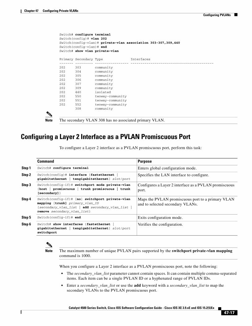
This example shows how to associate community VLANs 303 through 307 and 309, twoway-community VLANs 550 through 552, and isolated VLAN 440 with primary VLAN 202 and verify the configuration:
Command Purpose
Step 1 Switch# configure terminal Enters configuration mode.
Step 2 Switch(config)# vlan primary_vlan_ID Enters VLAN configuration mode for the primary VLAN.
Step 3 Switch(config-vlan)# private-vlan association {secondary_vlan_list | add secondary_vlan_list | remove secondary_vlan_list}
Associates the secondary VLAN with the primary VLAN.
The list can contain only one isolated VLAN ID; it can also contain multiple community or twoway-community VLAN IDs.
You can use the no keyword to clear all secondary associations.
Step 4 Switch(config-vlan)# end Exits VLAN configuration mode.
Step 5 Switch# show vlan private-vlan [type] Verifies the configuration.
47-16Catalyst 4500 Series Switch, Cisco IOS Software Configuration Guide - Cisco IOS XE 3.9.xE and IOS 15.2(5)Ex
Chapter 47 Configuring Private VLANsConfiguring PVLANs
Switch# configure terminal Switch(config)# vlan 202 Switch(config-vlan)# private-vlan association 303-307,309,440 Switch(config-vlan)# end Switch# show vlan private-vlan
Primary Secondary Type Interfaces------- --------- ----------------- ------------------------------------------202 303 community 202 304 community 202 305 community 202 306 community 202 307 community 202 309 community 202 440 isolated 202 550 twoway-community 202 551 twoway-community 202 552 twoway-community 308 community
Note The secondary VLAN 308 has no associated primary VLAN.
Configuring a Layer 2 Interface as a PVLAN Promiscuous PortTo configure a Layer 2 interface as a PVLAN promiscuous port, perform this task:
Note The maximum number of unique PVLAN pairs supported by the switchport private-vlan mapping command is 1000.
When you configure a Layer 2 interface as a PVLAN promiscuous port, note the following:
• The secondary_vlan_list parameter cannot contain spaces. It can contain multiple comma-separated items. Each item can be a single PVLAN ID or a hyphenated range of PVLAN IDs.
• Enter a secondary_vlan_list or use the add keyword with a secondary_vlan_list to map the secondary VLANs to the PVLAN promiscuous port.
Command Purpose
Step 1 Switch# configure terminal Enters global configuration mode.
Step 2 Switch(config)# interface {fastethernet | gigabitethernet | tengigabitethernet} slot/port
Specifies the LAN interface to configure.
Step 3 Switch(config-if)# switchport mode private-vlan {host | promiscuous | trunk promiscuous | trunk [secondary]}
Configures a Layer 2 interface as a PVLAN promiscuous port.
Step 4 Switch(config-if)# [no] switchport private-vlan mapping [trunk] primary_vlan_ID {secondary_vlan_list | add secondary_vlan_list | remove secondary_vlan_list}
Maps the PVLAN promiscuous port to a primary VLAN and to selected secondary VLANs.
Step 5 Switch(config-if)# end Exits configuration mode.
Step 6 Switch# show interfaces {fastethernet | gigabitethernet | tengigabitethernet} slot/port switchport
Verifies the configuration.
47-17Catalyst 4500 Series Switch, Cisco IOS Software Configuration Guide - Cisco IOS XE 3.9.xE and IOS 15.2(5)Ex

Chapter 47 Configuring Private VLANsConfiguring PVLANs
• Use the remove keyword with a secondary_vlan_list to clear the mapping between secondary VLANs and the PVLAN promiscuous port.
This example shows how to configure interface FastEthernet 5/2 as a PVLAN promiscuous port, map it to a PVLAN, and verify the configuration:
Switch# configure terminal Switch(config)# interface fastethernet 5/2 Switch(config-if)# switchport mode private-vlan promiscuous Switch(config-if)# switchport private-vlan mapping 200 2Switch(config-if)# end Switch# show interfaces fastethernet 5/2 switchportName:Fa5/2Switchport:EnabledAdministrative Mode:private-vlan promiscuousOperational Mode:private-vlan promiscuousAdministrative Trunking Encapsulation:negotiateOperational Trunking Encapsulation:nativeNegotiation of Trunking:OffAccess Mode VLAN:1 (default)Trunking Native Mode VLAN:1 (default)Voice VLAN:noneAdministrative Private VLAN Host Association:noneAdministrative Private VLAN Promiscuous Mapping:200 (VLAN0200) 2 (VLAN0002)Private VLAN Trunk Native VLAN:noneAdministrative Private VLAN Trunk Encapsulation:dot1qAdministrative Private VLAN Trunk Normal VLANs:noneAdministrative Private VLAN Trunk Private VLANs:noneOperational Private VLANs: 200 (VLAN0200) 2 (VLAN0002)Trunking VLANs Enabled:ALLPruning VLANs Enabled:2-1001Capture Mode DisabledCapture VLANs Allowed:ALL
Configuring a Layer 2 Interface as a PVLAN Host PortTo configure a Layer 2 interface as a PVLAN host port, perform this task:
Command Purpose
Step 1 Switch# configure terminal Enters configuration mode.
Step 2 Switch(config)# interface {fastethernet | gigabitethernet | tengigabitethernet} slot/port
Specifies the LAN port to configure.
Step 3 Switch(config-if)# switchport mode private-vlan {host | promiscuous | trunk promiscuous | trunk [secondary]}
Configures a Layer 2 interface as a PVLAN host port.
Step 4 Switch(config-if)# [no] switchport private-vlan host-association primary_vlan_ID secondary_vlan_ID
Associates the Layer 2 interface with a PVLAN.
You can use the no keyword to delete all associations from the primary VLAN.
Step 5 Switch(config-if)# end Exits configuration mode.
Step 6 Switch# show interfaces {fastethernet | gigabitethernet | tengigabitethernet} slot/port switchport
Verifies the configuration.
47-18Catalyst 4500 Series Switch, Cisco IOS Software Configuration Guide - Cisco IOS XE 3.9.xE and IOS 15.2(5)Ex

Chapter 47 Configuring Private VLANsConfiguring PVLANs
This example shows how to configure interface FastEthernet 5/1 as a PVLAN host port and verify the configuration:
Switch# configure terminal Switch(config)# interface fastethernet 5/1 Switch(config-if)# switchport mode private-vlan host Switch(config-if)# switchport private-vlan host-association 202 440
Switch(config-if)# end
Switch# show interfaces fastethernet 5/1 switchportName: Fa5/1Switchport: EnabledAdministrative Mode: private-vlan hostOperational Mode: private-vlan hostAdministrative Trunking Encapsulation: negotiateOperational Trunking Encapsulation: nativeNegotiation of Trunking: OffAccess Mode VLAN: 1 (default)Trunking Native Mode VLAN: 1 (default)Voice VLAN: noneAppliance trust: noneAdministrative Private Vlan Host Association: 202 (VLAN0202) 440 (VLAN0440) Promiscuous Mapping: none Trunk encapsulation : dot1q Trunk vlans:Operational private-vlan(s): 202 (VLAN0202) 440 (VLAN0440) Trunking VLANs Enabled: ALLPruning VLANs Enabled: 2-1001Capture Mode DisabledCapture VLANs Allowed: ALL
Configuring a Layer 2 Interface as an Isolated PVLAN Trunk PortTo configure a Layer 2 interface as an isolated PVLAN trunk port, perform this task:
Command Purpose
Step 1 Switch# configure terminal Enters global configuration mode.
Step 2 Switch(config)# interface {fastethernet | gigabitethernet | tengigabitethernet} slot/port
Specifies the LAN port to configure.
Step 3 Switch(config-if)# switchport mode private-vlan {host | promiscuous | trunk promiscuous | trunk [secondary]}
Configures a Layer 2 interface as a PVLAN trunk port.
47-19Catalyst 4500 Series Switch, Cisco IOS Software Configuration Guide - Cisco IOS XE 3.9.xE and IOS 15.2(5)Ex

Chapter 47 Configuring Private VLANsConfiguring PVLANs
This example shows how to configure interface FastEthernet 5/2 as a secondary trunk port, and verify the configuration:
Switch# configure terminal Switch(config)# interface fastethernet 5/2 Switch(config-if)# switchport mode private-vlan trunk secondarySwitch(config-if)# switchport private-vlan trunk native vlan 10Switch(config-if)# switchport private-vlan trunk allowed vlan 10. 3-4Switch(config-if)# switchport private-vlan association trunk 3 301Switch(config-if)# end Switch# show interfaces fastethernet 5/2 switchportName: Fa5/2
Switchport: EnabledAdministrative Mode: private-vlan trunk secondary Operational Mode: private-vlan trunk secondary Administrative Trunking Encapsulation: negotiate Operational Trunking Encapsulation: dot1q Negotiation of Trunking: On Access Mode VLAN: 1 (default)
Step 4 Switch(config-if)# [no] switchport private-vlan association trunk primary_vlan_ID secondary_vlan_ID
Configures association between primary VLANs and secondary VLANs the PVLAN trunk port with a PVLAN.
Note Multiple PVLAN pairs can be specified using this command so that a PVLAN trunk port can carry multiple secondary VLANs. If an association is specified for the existing primary VLAN, the existing association is replaced. If there is no trunk association, any packets received on secondary VLANs are dropped.
You can use the no keyword to delete all associations from the primary VLAN.
Step 5 Switch(config-if)# [no] switchport private-vlan trunk allowed vlan vlan_list all | none | [add | remove | except] vlan_atom[,vlan_atom...]
Configures a list of allowed normal VLANs on a PVLAN trunk port.
You can use the no keyword to remove all allowed normal VLANs on a PVLAN trunk port.
Step 6 Switch(config-if)# switchport private-vlan trunk native vlan vlan_id
Configures a VLAN to which untagged packets (as in IEEE 802.1Q tagging) are assigned on a PVLAN trunk port.
If there is no native VLAN configured, all untagged packets are dropped.
If the native VLAN is a secondary VLAN and the port does not have the association for the secondary VLAN, the untagged packets are dropped.
You can use the no keyword to remove all native VLANs on a PVLAN trunk port.
Step 7 Switch(config-if)# end Exits configuration mode.
Step 8 Switch# show interfaces {fastethernet | gigabitethernet | tengigabitethernet} slot/port switchport
Verifies the configuration.
Command Purpose
47-20Catalyst 4500 Series Switch, Cisco IOS Software Configuration Guide - Cisco IOS XE 3.9.xE and IOS 15.2(5)Ex
Chapter 47 Configuring Private VLANsConfiguring PVLANs
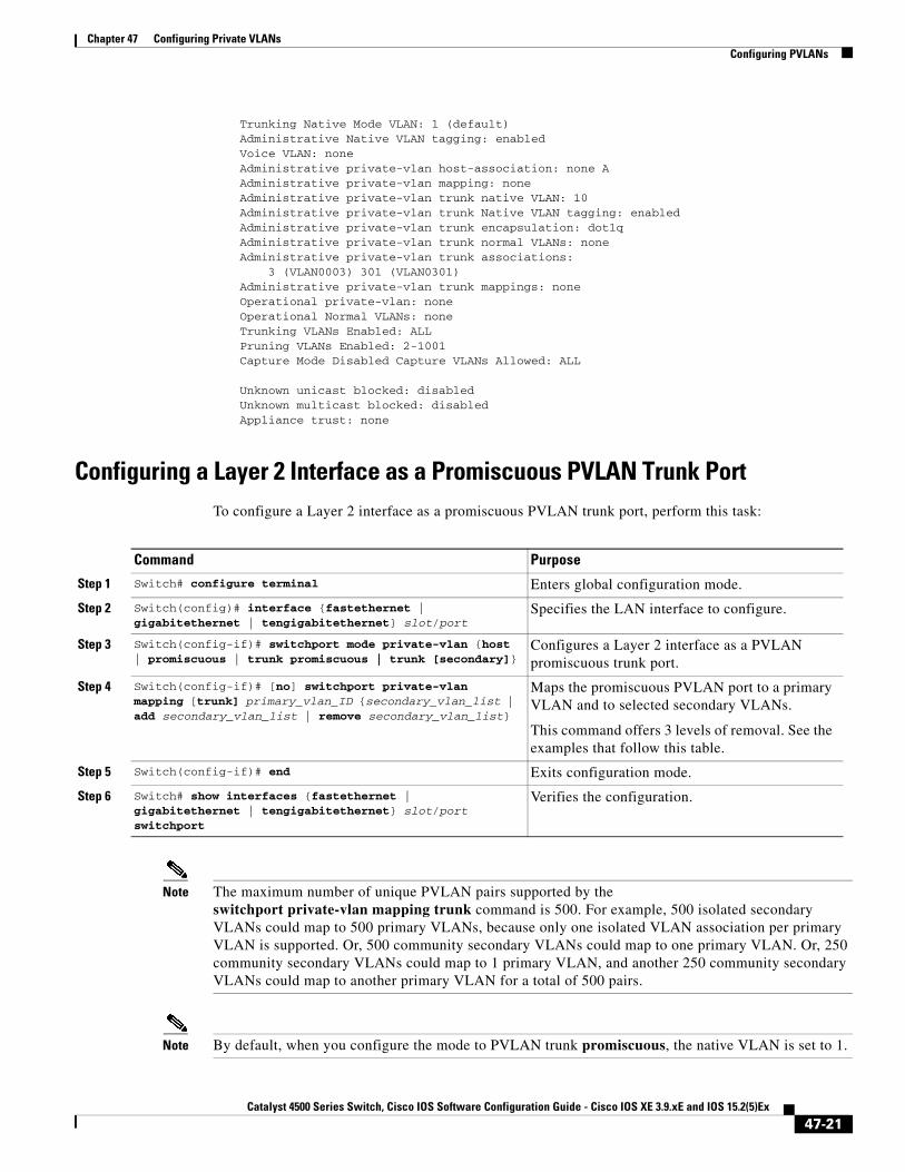
Trunking Native Mode VLAN: 1 (default) Administrative Native VLAN tagging: enabled Voice VLAN: none Administrative private-vlan host-association: none AAdministrative private-vlan mapping: none Administrative private-vlan trunk native VLAN: 10 Administrative private-vlan trunk Native VLAN tagging: enabled Administrative private-vlan trunk encapsulation: dot1q Administrative private-vlan trunk normal VLANs: none Administrative private-vlan trunk associations: 3 (VLAN0003) 301 (VLAN0301)Administrative private-vlan trunk mappings: none Operational private-vlan: none Operational Normal VLANs: none Trunking VLANs Enabled: ALL Pruning VLANs Enabled: 2-1001 Capture Mode Disabled Capture VLANs Allowed: ALL
Unknown unicast blocked: disabledUnknown multicast blocked: disabledAppliance trust: none
Configuring a Layer 2 Interface as a Promiscuous PVLAN Trunk PortTo configure a Layer 2 interface as a promiscuous PVLAN trunk port, perform this task:
Note The maximum number of unique PVLAN pairs supported by the switchport private-vlan mapping trunk command is 500. For example, 500 isolated secondary VLANs could map to 500 primary VLANs, because only one isolated VLAN association per primary VLAN is supported. Or, 500 community secondary VLANs could map to one primary VLAN. Or, 250 community secondary VLANs could map to 1 primary VLAN, and another 250 community secondary VLANs could map to another primary VLAN for a total of 500 pairs.
Note By default, when you configure the mode to PVLAN trunk promiscuous, the native VLAN is set to 1.
Command Purpose
Step 1 Switch# configure terminal Enters global configuration mode.
Step 2 Switch(config)# interface {fastethernet | gigabitethernet | tengigabitethernet} slot/port
Specifies the LAN interface to configure.
Step 3 Switch(config-if)# switchport mode private-vlan {host | promiscuous | trunk promiscuous | trunk [secondary]}
Configures a Layer 2 interface as a PVLAN promiscuous trunk port.
Step 4 Switch(config-if)# [no] switchport private-vlan mapping [trunk] primary_vlan_ID {secondary_vlan_list | add secondary_vlan_list | remove secondary_vlan_list}
Maps the promiscuous PVLAN port to a primary VLAN and to selected secondary VLANs.
This command offers 3 levels of removal. See the examples that follow this table.
Step 5 Switch(config-if)# end Exits configuration mode.
Step 6 Switch# show interfaces {fastethernet | gigabitethernet | tengigabitethernet} slot/port switchport
Verifies the configuration.
47-21Catalyst 4500 Series Switch, Cisco IOS Software Configuration Guide - Cisco IOS XE 3.9.xE and IOS 15.2(5)Ex
Chapter 47 Configuring Private VLANsConfiguring PVLANs
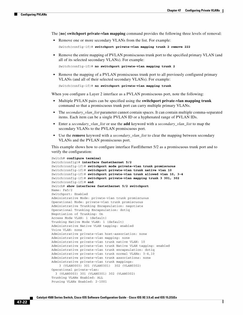
The [no] switchport private-vlan mapping command provides the following three levels of removal:
• Remove one or more secondary VLANs from the list. For example:
Switch(config-if)# switchport private-vlan mapping trunk 2 remove 222
• Remove the entire mapping of PVLAN promiscuous trunk port to the specified primary VLAN (and all of its selected secondary VLANs). For example:
Switch(config-if)# no switchport private-vlan mapping trunk 2
• Remove the mapping of a PVLAN promiscuous trunk port to all previously configured primary VLANs (and all of their selected secondary VLANs). For example:
Switch(config-if)# no switchport private-vlan mapping trunk
When you configure a Layer 2 interface as a PVLAN promiscuous port, note the following:
• Multiple PVLAN pairs can be specified using the switchport private-vlan mapping trunk command so that a promiscuous trunk port can carry multiple primary VLANs.
• The secondary_vlan_list parameter cannot contain spaces. It can contain multiple comma-separated items. Each item can be a single PVLAN ID or a hyphenated range of PVLAN IDs.
• Enter a secondary_vlan_list or use the add keyword with a secondary_vlan_list to map the secondary VLANs to the PVLAN promiscuous port.
• Use the remove keyword with a secondary_vlan_list to clear the mapping between secondary VLANs and the PVLAN promiscuous port.
This example shows how to configure interface FastEthernet 5/2 as a promiscuous trunk port and to verify the configuration:
Switch# configure terminal Switch(config)# interface fastethernet 5/2 Switch(config-if)# switchport mode private-vlan trunk promiscuousSwitch(config-if)# switchport private-vlan trunk native vlan 10Switch(config-if)# switchport private-vlan trunk allowed vlan 10, 3-4Switch(config-if)# switchport private-vlan mapping trunk 3 301, 302Switch(config-if)# end Switch# show interfaces fastethernet 5/2 switchportName: Fa5/2Switchport: EnabledAdministrative Mode: private-vlan trunk promiscuous Operational Mode: private-vlan trunk promiscuous Administrative Trunking Encapsulation: negotiate Operational Trunking Encapsulation: dot1q Negotiation of Trunking: On Access Mode VLAN: 1 (default) Trunking Native Mode VLAN: 1 (default) Administrative Native VLAN tagging: enabled Voice VLAN: none Administrative private-vlan host-association: none Administrative private-vlan mapping: none Administrative private-vlan trunk native VLAN: 10 Administrative private-vlan trunk Native VLAN tagging: enabled Administrative private-vlan trunk encapsulation: dot1q Administrative private-vlan trunk normal VLANs: 3-4,10 Administrative private-vlan trunk associations: none Administrative private-vlan trunk mappings: 3 (VLAN0003) 301 (VLAN0301) 302 (VLAN0302) Operational private-vlan: 3 (VLAN0003) 301 (VLAN0301) 302 (VLAN0302) Trunking VLANs Enabled: ALL Pruning VLANs Enabled: 2-1001
47-22Catalyst 4500 Series Switch, Cisco IOS Software Configuration Guide - Cisco IOS XE 3.9.xE and IOS 15.2(5)Ex
Chapter 47 Configuring Private VLANsConfiguring PVLANs
Capture Mode Disabled Capture VLANs Allowed: ALL
Unknown unicast blocked: disabledUnknown multicast blocked: disabledAppliance trust: none
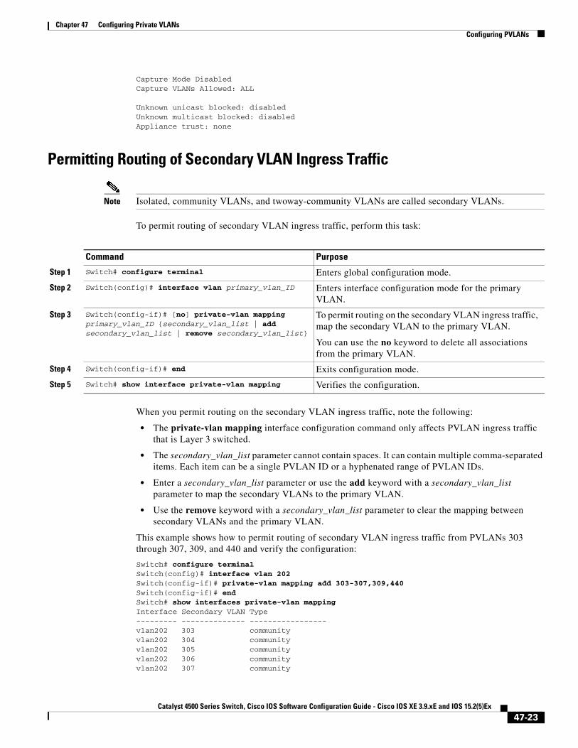
Permitting Routing of Secondary VLAN Ingress Traffic
Note Isolated, community VLANs, and twoway-community VLANs are called secondary VLANs.
To permit routing of secondary VLAN ingress traffic, perform this task:
When you permit routing on the secondary VLAN ingress traffic, note the following:
• The private-vlan mapping interface configuration command only affects PVLAN ingress traffic that is Layer 3 switched.
• The secondary_vlan_list parameter cannot contain spaces. It can contain multiple comma-separated items. Each item can be a single PVLAN ID or a hyphenated range of PVLAN IDs.
• Enter a secondary_vlan_list parameter or use the add keyword with a secondary_vlan_list parameter to map the secondary VLANs to the primary VLAN.
• Use the remove keyword with a secondary_vlan_list parameter to clear the mapping between secondary VLANs and the primary VLAN.
This example shows how to permit routing of secondary VLAN ingress traffic from PVLANs 303 through 307, 309, and 440 and verify the configuration:
Switch# configure terminal Switch(config)# interface vlan 202 Switch(config-if)# private-vlan mapping add 303-307,309,440 Switch(config-if)# end Switch# show interfaces private-vlan mapping Interface Secondary VLAN Type--------- -------------- -----------------vlan202 303 communityvlan202 304 communityvlan202 305 communityvlan202 306 communityvlan202 307 community
Command Purpose
Step 1 Switch# configure terminal Enters global configuration mode.
Step 2 Switch(config)# interface vlan primary_vlan_ID Enters interface configuration mode for the primary VLAN.
Step 3 Switch(config-if)# [no] private-vlan mapping primary_vlan_ID {secondary_vlan_list | add secondary_vlan_list | remove secondary_vlan_list}
To permit routing on the secondary VLAN ingress traffic, map the secondary VLAN to the primary VLAN.
You can use the no keyword to delete all associations from the primary VLAN.
Step 4 Switch(config-if)# end Exits configuration mode.
Step 5 Switch# show interface private-vlan mapping Verifies the configuration.
47-23Catalyst 4500 Series Switch, Cisco IOS Software Configuration Guide - Cisco IOS XE 3.9.xE and IOS 15.2(5)Ex
Chapter 47 Configuring Private VLANsConfiguring PVLANs
vlan202 309 communityvlan202 440 isolated
Switch#
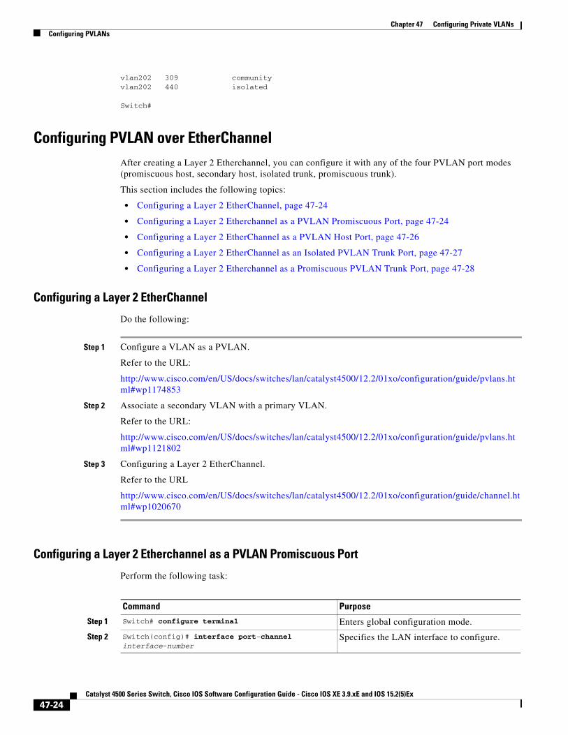
Configuring PVLAN over EtherChannelAfter creating a Layer 2 Etherchannel, you can configure it with any of the four PVLAN port modes (promiscuous host, secondary host, isolated trunk, promiscuous trunk).
This section includes the following topics:
• Configuring a Layer 2 EtherChannel, page 47-24
• Configuring a Layer 2 Etherchannel as a PVLAN Promiscuous Port, page 47-24
• Configuring a Layer 2 EtherChannel as a PVLAN Host Port, page 47-26
• Configuring a Layer 2 EtherChannel as an Isolated PVLAN Trunk Port, page 47-27
• Configuring a Layer 2 Etherchannel as a Promiscuous PVLAN Trunk Port, page 47-28
Configuring a Layer 2 EtherChannel
Do the following:
Step 1 Configure a VLAN as a PVLAN.
Refer to the URL:
http://www.cisco.com/en/US/docs/switches/lan/catalyst4500/12.2/01xo/configuration/guide/pvlans.html#wp1174853
Step 2 Associate a secondary VLAN with a primary VLAN.
Refer to the URL:
http://www.cisco.com/en/US/docs/switches/lan/catalyst4500/12.2/01xo/configuration/guide/pvlans.html#wp1121802
Step 3 Configuring a Layer 2 EtherChannel.
Refer to the URL
http://www.cisco.com/en/US/docs/switches/lan/catalyst4500/12.2/01xo/configuration/guide/channel.html#wp1020670
Configuring a Layer 2 Etherchannel as a PVLAN Promiscuous Port
Perform the following task:
Command Purpose
Step 1 Switch# configure terminal Enters global configuration mode.
Step 2 Switch(config)# interface port-channel interface-number
Specifies the LAN interface to configure.
47-24Catalyst 4500 Series Switch, Cisco IOS Software Configuration Guide - Cisco IOS XE 3.9.xE and IOS 15.2(5)Ex
Chapter 47 Configuring Private VLANsConfiguring PVLANs
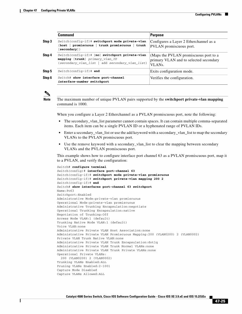
Note The maximum number of unique PVLAN pairs supported by the switchport private-vlan mapping command is 1000.
When you configure a Layer 2 Etherchannel as a PVLAN promiscuous port, note the following:
• The secondary_vlan_list parameter cannot contain spaces. It can contain multiple comma-separated items. Each item can be a single PVLAN ID or a hyphenated range of PVLAN IDs.
• Enter a secondary_vlan_list or use the add keyword with a secondary_vlan_list to map the secondary VLANs to the PVLAN promiscuous port.
• Use the remove keyword with a secondary_vlan_list to clear the mapping between secondary VLANs and the PVLAN promiscuous port.
This example shows how to configure interface port channel 63 as a PVLAN promiscuous port, map it to a PVLAN, and verify the configuration:
Switch# configure terminalSwitch(config)# interface port-channel 63Switch(config-if)# switchport mode private-vlan promiscuousSwitch(config-if)# switchport private-vlan mapping 200 2Switch(config-if)# endSwitch# show interfaces port-channel 63 switchportName:Po63Switchport:EnabledAdministrative Mode:private-vlan promiscuousOperational Mode:private-vlan promiscuousAdministrative Trunking Encapsulation:negotiateOperational Trunking Encapsulation:nativeNegotiation of Trunking:OffAccess Mode VLAN:1 (default)Trunking Native Mode VLAN:1 (default)Voice VLAN:noneAdministrative Private VLAN Host Association:noneAdministrative Private VLAN Promiscuous Mapping:200 (VLAN0200) 2 (VLAN0002)Private VLAN Trunk Native VLAN:noneAdministrative Private VLAN Trunk Encapsulation:dot1qAdministrative Private VLAN Trunk Normal VLANs:noneAdministrative Private VLAN Trunk Private VLANs:noneOperational Private VLANs: 200 (VLAN0200) 2 (VLAN0002)Trunking VLANs Enabled:ALLPruning VLANs Enabled:2-1001Capture Mode DisabledCapture VLANs Allowed:ALL
Step 3 Switch(config-if)# switchport mode private-vlan {host | promiscuous | trunk promiscuous | trunk [secondary]}
Configures a Layer 2 Etherchannel as a PVLAN promiscuous port.
Step 4 Switch(config-if)# [no] switchport private-vlan mapping [trunk] primary_vlan_ID {secondary_vlan_list | add secondary_vlan_list}
(Maps the PVLAN promiscuous port to a primary VLAN and to selected secondary VLANs.
Step 5 Switch(config-if)# end Exits configuration mode.
Step 6 Switch# show interface port-channel interface-number switchport
Verifies the configuration.
Command Purpose
47-25Catalyst 4500 Series Switch, Cisco IOS Software Configuration Guide - Cisco IOS XE 3.9.xE and IOS 15.2(5)Ex

Chapter 47 Configuring Private VLANsConfiguring PVLANs
Configuring a Layer 2 EtherChannel as a PVLAN Host Port
To configure a Layer 2 EtherChannel as a PVLAN host port, perform this task:
This example shows how to configure interface port channel 63 as a PVLAN host port and to verify the configuration:
Switch# configure terminal Switch(config)# interface port-channel 63Switch(config-if)# switchport mode private-vlan host Switch(config-if)# switchport private-vlan host-association 202 440Switch(config-if)# endSwitch# show interfaces port-channel 63 switchportName: Po63Switchport: EnabledAdministrative Mode: private-vlan hostOperational Mode: private-vlan hostAdministrative Trunking Encapsulation: negotiateOperational Trunking Encapsulation: nativeNegotiation of Trunking: OffAccess Mode VLAN: 1 (default)Trunking Native Mode VLAN: 1 (default)Voice VLAN: noneAppliance trust: noneAdministrative Private Vlan Host Association: 202 (VLAN0202) 440 (VLAN0440) Promiscuous Mapping: none Trunk encapsulation : dot1q Trunk vlans:Operational private-vlan(s): 202 (VLAN0202) 440 (VLAN0440) Trunking VLANs Enabled: ALLPruning VLANs Enabled: 2-1001Capture Mode DisabledCapture VLANs Allowed: ALL
Command Purpose
Step 1 Switch# configure terminal Enters global configuration mode.
Step 2 Switch(config)# interface port-channel interface-number
Specifies the LAN interface to configure.
Step 3 Switch(config-if)# switchport mode private-vlan {host | promiscuous | trunk promiscuous | trunk [secondary]}
Configures a Layer 2 Etherchannel as a PVLAN host port.
Step 4 Switch(config-if)# [no] switchport private-vlan host-association primary_vlanb_ID secondary_vlan_ID
Associates the Layer 2 interface with a PVLAN.
You can use the no keyword to delete all associations from the primary VLAN.
Step 5 Switch(config-if)# end Exits configuration mode.
Step 6 Switch# show interface port-channel interface-number switchport
Verifies the configuration.
47-26Catalyst 4500 Series Switch, Cisco IOS Software Configuration Guide - Cisco IOS XE 3.9.xE and IOS 15.2(5)Ex
Chapter 47 Configuring Private VLANsConfiguring PVLANs
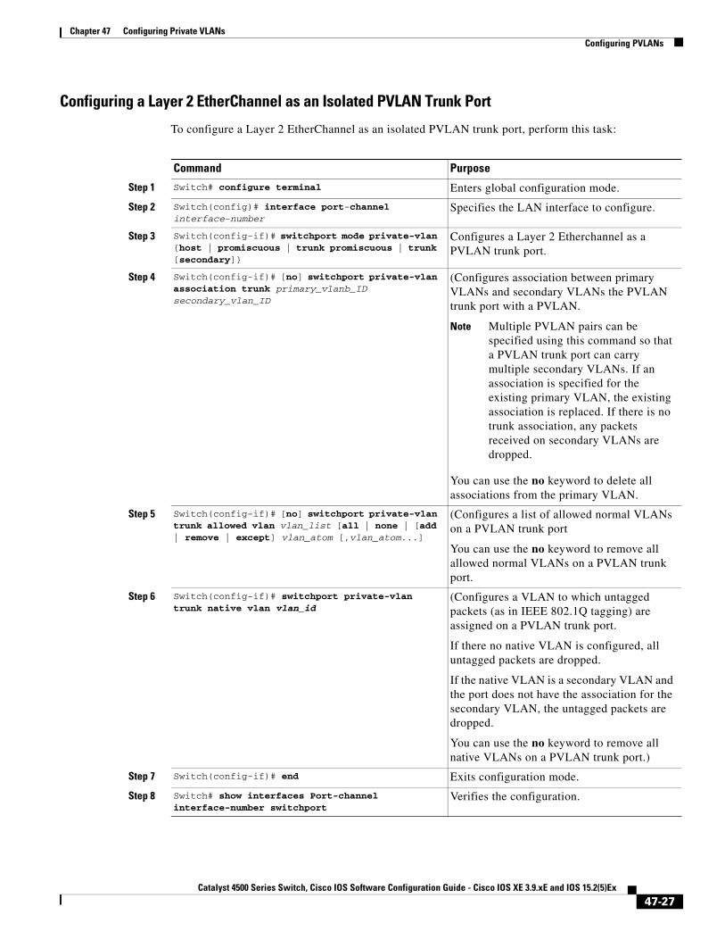
Configuring a Layer 2 EtherChannel as an Isolated PVLAN Trunk Port
To configure a Layer 2 EtherChannel as an isolated PVLAN trunk port, perform this task:
Command Purpose
Step 1 Switch# configure terminal Enters global configuration mode.
Step 2 Switch(config)# interface port-channel interface-number
Specifies the LAN interface to configure.
Step 3 Switch(config-if)# switchport mode private-vlan {host | promiscuous | trunk promiscuous | trunk [secondary]}
Configures a Layer 2 Etherchannel as a PVLAN trunk port.
Step 4 Switch(config-if)# [no] switchport private-vlan association trunk primary_vlanb_ID secondary_vlan_ID
(Configures association between primary VLANs and secondary VLANs the PVLAN trunk port with a PVLAN.
Note Multiple PVLAN pairs can be specified using this command so that a PVLAN trunk port can carry multiple secondary VLANs. If an association is specified for the existing primary VLAN, the existing association is replaced. If there is no trunk association, any packets received on secondary VLANs are dropped.
You can use the no keyword to delete all associations from the primary VLAN.
Step 5 Switch(config-if)# [no] switchport private-vlan trunk allowed vlan vlan_list [all | none | [add | remove | except] vlan_atom [,vlan_atom...]
(Configures a list of allowed normal VLANs on a PVLAN trunk port
You can use the no keyword to remove all allowed normal VLANs on a PVLAN trunk port.
Step 6 Switch(config-if)# switchport private-vlan trunk native vlan vlan_id
(Configures a VLAN to which untagged packets (as in IEEE 802.1Q tagging) are assigned on a PVLAN trunk port.
If there no native VLAN is configured, all untagged packets are dropped.
If the native VLAN is a secondary VLAN and the port does not have the association for the secondary VLAN, the untagged packets are dropped.
You can use the no keyword to remove all native VLANs on a PVLAN trunk port.)
Step 7 Switch(config-if)# end Exits configuration mode.
Step 8 Switch# show interfaces Port-channel interface-number switchport
Verifies the configuration.
47-27Catalyst 4500 Series Switch, Cisco IOS Software Configuration Guide - Cisco IOS XE 3.9.xE and IOS 15.2(5)Ex

Chapter 47 Configuring Private VLANsConfiguring PVLANs
This example shows how to configure interface port channel 63 as a secondary trunk port, and to verify the configuration:
Switch# configure terminal Switch(config)# interface port-channel 63Switch(config-if)# switchport mode private-vlan trunk secondarySwitch(config-if)# switchport private-vlan trunk native vlan 10Switch(config-if)# switchport private-vlan trunk allowed vlan 10. 3-4Switch(config-if)# switchport private-vlan association trunk 3 301Switch(config-if)# end Switch# show interfaces port-channel 63 switchportName: Po63Switchport: EnabledAdministrative Mode: private-vlan trunk secondary Operational Mode: private-vlan trunk secondary Administrative Trunking Encapsulation: negotiate Operational Trunking Encapsulation: dot1q Negotiation of Trunking: On Access Mode VLAN: 1 (default) Trunking Native Mode VLAN: 1 (default) Administrative Native VLAN tagging: enabled Voice VLAN: none Administrative private-vlan host-association: none Administrative private-vlan mapping: none Administrative private-vlan trunk native VLAN: 10 Administrative private-vlan trunk Native VLAN tagging: enabled Administrative private-vlan trunk encapsulation: dot1q Administrative private-vlan trunk normal VLANs: none Administrative private-vlan trunk associations: 3 (VLAN0003) 301 (VLAN0301)Administrative private-vlan trunk mappings: none Operational private-vlan: none Operational Normal VLANs: none Trunking VLANs Enabled: ALL Pruning VLANs Enabled: 2-1001 Capture Mode Disabled Capture VLANs Allowed: ALLUnknown unicast blocked: disabledUnknown multicast blocked: disabledAppliance trust: none
Configuring a Layer 2 Etherchannel as a Promiscuous PVLAN Trunk Port
To configure a Layer 2 Etherchannel as a promiscuous PVLAN trunk port, perform this task:
Command Purpose
Step 1 Switch# configure terminal Enters global configuration mode.
Step 2 Switch(config)# interface port-channel interface-number
Specifies the LAN interface to configure.
Step 3 Switch(config-if)# switchport mode private-vlan {host | promiscuous | trunk promiscuous | trunk [secondary]}
Configures a Layer 2 Etherchannel as a PVLAN promiscuous trunk port.
Step 4 Switch(config-if)# [no] switchport private-vlan mapping [trunk] primary_vlan_ID {secondary_vlan_list | add secondary_vlan_list | remove secondary_vlan_list}
Maps the promiscuous PVLAN port to a primary VLAN and to the selected secondary VLANs.
This command offers 3 levels of removal.
47-28Catalyst 4500 Series Switch, Cisco IOS Software Configuration Guide - Cisco IOS XE 3.9.xE and IOS 15.2(5)Ex

Chapter 47 Configuring Private VLANsConfiguring PVLANs
Note The maximum number of unique PVLAN pairs supported by the switchport private-vlan mapping trunk command is 500. For example, 500 isolated secondary VLANs could map to 500 primary VLANs, because only one isolated VLAN association per primary VLAN is supported. Or, 500 community secondary VLANs could map to one primary VLAN. Or, 250 community secondary VLANs could map to 1 primary VLAN, and another 250 community secondary VLANs could map to another primary VLAN for a total of 500 pairs.
Note By default, when you configure the mode to private VLAN trunk promiscuous, the native VLAN is set to 1.
The [no] switchport private-vlan mapping command provides the following three levels of removal:
• Remove one or more secondary VLANs from the list.
For example:
Switch(config-if)# switchport private-vlan mapping trunk 2 remove 222
• Remove the entire mapping of PVLAN promiscuous trunk port to the specified primary VLAN (and all of its selected secondary VLANs).
For example:
Switch(config-if)# no switchport private-vlan mapping trunk 2
• Remove the mapping of a PVLAN promiscuous trunk port to all previously configured primary VLANs (and all of their selected secondary VLANs).
For example:
Switch(config-if)# no switchport private-vlan mapping trunk
When you configure a Layer 2 etherchannel as a PVLAN promiscuous trunk port, observe that multiple private VLAN pairs can be specified with the switchport private-vlan mapping trunk command so that a promiscuous trunk port can carry multiple primary VLANs.
•The secondary_vlan_list parameter cannot contain spaces. It can contain multiple comma-separated items. Each item can be a single PVLAN ID or a hyphenated range of PVLAN IDs.
•Enter a secondary_vlan_list or use the add keyword with a secondary_vlan_list to map the secondary VLANs to the PVLAN promiscuous port.
•Use the remove keyword with a secondary_vlan_list to clear the mapping between secondary VLANs and the PVLAN promiscuous port.
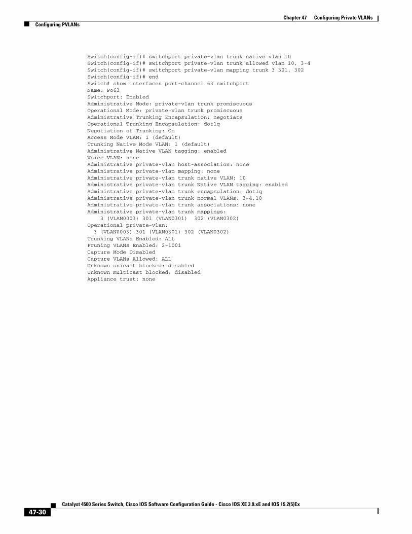
This example shows how to configure interface Port-channel 63 as a promiscuous trunk port and to verify the configuration:
Switch# configure terminal Switch(config)# interface port-channel 63 Switch(config-if)# switchport mode private-vlan trunk promiscuous
Step 5 Switch(config-if)# end Exits configuration mode.
Step 6 Switch# show interfaces port-channel interface-number switchport
Verifies the configuration.
Command Purpose
47-29Catalyst 4500 Series Switch, Cisco IOS Software Configuration Guide - Cisco IOS XE 3.9.xE and IOS 15.2(5)Ex
Chapter 47 Configuring Private VLANsConfiguring PVLANs
Switch(config-if)# switchport private-vlan trunk native vlan 10Switch(config-if)# switchport private-vlan trunk allowed vlan 10, 3-4Switch(config-if)# switchport private-vlan mapping trunk 3 301, 302Switch(config-if)# end Switch# show interfaces port-channel 63 switchportName: Po63Switchport: EnabledAdministrative Mode: private-vlan trunk promiscuous Operational Mode: private-vlan trunk promiscuous Administrative Trunking Encapsulation: negotiate Operational Trunking Encapsulation: dot1q Negotiation of Trunking: On Access Mode VLAN: 1 (default) Trunking Native Mode VLAN: 1 (default) Administrative Native VLAN tagging: enabled Voice VLAN: none Administrative private-vlan host-association: none Administrative private-vlan mapping: none Administrative private-vlan trunk native VLAN: 10 Administrative private-vlan trunk Native VLAN tagging: enabled Administrative private-vlan trunk encapsulation: dot1q Administrative private-vlan trunk normal VLANs: 3-4,10 Administrative private-vlan trunk associations: none Administrative private-vlan trunk mappings: 3 (VLAN0003) 301 (VLAN0301) 302 (VLAN0302) Operational private-vlan: 3 (VLAN0003) 301 (VLAN0301) 302 (VLAN0302) Trunking VLANs Enabled: ALL Pruning VLANs Enabled: 2-1001 Capture Mode Disabled Capture VLANs Allowed: ALLUnknown unicast blocked: disabledUnknown multicast blocked: disabledAppliance trust: none
47-30Catalyst 4500 Series Switch, Cisco IOS Software Configuration Guide - Cisco IOS XE 3.9.xE and IOS 15.2(5)Ex
Related Documents