Configuring IEEE 802.1ad Provider networks handle traffic from a large number of customers. It is important that one customer’s traffic is isolated from the other customer’s traffic. IEEE 802.1ad enables the service providers to use the architecture and protocols of IEEE 802.1Q to offer separate LANs, bridged local area networks, or virtual bridged local area networks to a number of customers, with minimal cooperation or no cooperation between each customer and the service provider. IEEE 802.1ad implements standard protocols for double tagging of data. The data traffic coming from the customer side are double tagged in the provider network where the inner tag is the customer-tag (C-tag) and the outer tag is the provider-tag (S-tag). The control packets are tunneled by changing the destination MAC address in the provider network. A service provider's Layer 2 network transports the subscriber's Layer 2 protocols transparently. Provider Bridge allows the service provider switches to transparently carry customer Layer 2 control frames, such as spanning tree Bridge Protocol Data Units (BPDUs) or Cisco proprietary protocol frames such as Cisco Discovery Protocol (CDP) without mixing the service provider's own traffic and with other customer traffic in the service provider's network. A provider bridge is just like a standard 802.1Q bridge, but it imposes a set of requirements, defined by IEEE 802.1ad standards, on a port in a provider bridge which interfaces to customer. This port is a UNI Port. 802.1ad Provider Bridge thus achieves the same functionality as being addressed with L2PT and QinQ. When Connectivity Fault Management (CFM) is configured on 802.1ad interfaces, all CFM, Link Ethernet Operations, Administration, and Maintenance (OAM), Enhanced Local Management Interface (ELMI) or Y.1731 performance monitoring packets have their own peer or data rules depending on the type of 802.1ad port configured. • Finding Feature Information, on page 2 • Prerequisites for 802.1ad, on page 2 • Restrictions for 802.1ad, on page 2 • Information About 802.1ad, on page 3 • How to Configure 802.1ad, on page 8 • Verifying IEEE 802.1ad, on page 15 • Additional References, on page 16 • Feature Information for IEEE 802.1ad, on page 17 Configuring IEEE 802.1ad 1

Welcome message from author
This document is posted to help you gain knowledge. Please leave a comment to let me know what you think about it! Share it to your friends and learn new things together.
Transcript

Configuring IEEE 802.1ad
Provider networks handle traffic from a large number of customers. It is important that one customer’s trafficis isolated from the other customer’s traffic.
IEEE 802.1ad enables the service providers to use the architecture and protocols of IEEE 802.1Q to offerseparate LANs, bridged local area networks, or virtual bridged local area networks to a number of customers,with minimal cooperation or no cooperation between each customer and the service provider.
IEEE 802.1ad implements standard protocols for double tagging of data. The data traffic coming from thecustomer side are double tagged in the provider network where the inner tag is the customer-tag (C-tag) andthe outer tag is the provider-tag (S-tag). The control packets are tunneled by changing the destination MACaddress in the provider network.
A service provider's Layer 2 network transports the subscriber's Layer 2 protocols transparently. ProviderBridge allows the service provider switches to transparently carry customer Layer 2 control frames, such asspanning tree Bridge Protocol Data Units (BPDUs) or Cisco proprietary protocol frames such as CiscoDiscovery Protocol (CDP) without mixing the service provider's own traffic and with other customer trafficin the service provider's network. A provider bridge is just like a standard 802.1Q bridge, but it imposes a setof requirements, defined by IEEE 802.1ad standards, on a port in a provider bridge which interfaces to customer.This port is a UNI Port. 802.1ad Provider Bridge thus achieves the same functionality as being addressed withL2PT and QinQ.
When Connectivity Fault Management (CFM) is configured on 802.1ad interfaces, all CFM, Link EthernetOperations, Administration, and Maintenance (OAM), Enhanced Local Management Interface (ELMI) orY.1731 performance monitoring packets have their own peer or data rules depending on the type of 802.1adport configured.
• Finding Feature Information, on page 2• Prerequisites for 802.1ad, on page 2• Restrictions for 802.1ad, on page 2• Information About 802.1ad, on page 3• How to Configure 802.1ad, on page 8• Verifying IEEE 802.1ad, on page 15• Additional References, on page 16• Feature Information for IEEE 802.1ad, on page 17
Configuring IEEE 802.1ad1

Finding Feature InformationYour software release may not support all the features documented in this module. For the latest caveats andfeature information, see Bug Search Tool and the release notes for your platform and software release. Tofind information about the features documented in this module, and to see a list of the releases in which eachfeature is supported, see the feature information table.
Use Cisco Feature Navigator to find information about platform support and Cisco software image support.To access Cisco Feature Navigator, go to www.cisco.com/go/cfn. An account on Cisco.com is not required.
Prerequisites for 802.1ad• Ethertype should be configured.
Restrictions for 802.1ad• 802.1ad is supported only on EFP and Trunk EFPs (TEFP).
• Termination of Layer3 interfaces is not supported.
• QoS support is same as supported on the 802.1q EVCs.
• Routing over BDI with 802.1ad EVC is not supported.
• Outer tag Ethertype 0X88a8 is only supported.
• Global dot1ad command is not supported.
• Ethernet 802.1ad is not supported on port-channels.
• VPLS is not supported for 802.1ad.
• l2protocol peer and l2protocol drop commands are not supported.
• NNI port does not drop packets with dot1q outer tag.
• Encapsulation dot1ad <dot1q> on NNI ports with rewrite configured as rewrite ingress tag pop
2 symm at egress results in pushing 2 dot1q tags. It is advised not to use pop 2.
Rewrite Configuration Model for 802.1ad Ports
This section is not applicable for RSP3 ModuleNote
The table describes the rewrite configuration supported on service instances for the C-UNI, S-UNI and NNIports
Configuring IEEE 802.1ad2
Configuring IEEE 802.1adFinding Feature Information

Egress DirectionIngress DirectionRewritePort
Bridge Domain
Not supportedSupportedPushC-UNI
S-UNI
Not supportedSupportedPopNNI
SupportedNot supportedPush
Trunk EFP
SupportedSupportedPopC-UNI
NANANAS-UNI
Not supportedSupportedPopNNI
SupportedNot supportedPush
Cross Connect
Not supportedSupportedPushC-UNI
S-UNI
NANANANNI
Information About 802.1ad
802.1ad PortsIn 802.1ad, a port is configured as either a customer user-network interface (C-UNI), a service-provider UNI(S-UNI), or a network-to-network interface (NNI). Only Layer 2 interfaces can be 802.1ad ports.
• C-UNI—an be either an access port or an 802.1Q trunk port. The port uses the customer bridge addresses.To configure a C-UNI port, enter the ethernet dot1ad uni c-port interface configuration command.
• S-UNI—an access port that provides the same service to all customer VLANs entering the interface,marking all C-VLANs entering the port with the same S-VLAN. In this mode, the customer's port isconfigured as a trunk port, and traffic entering the S-UNI is tagged. Use the ethernet dot1ad uni s-portinterface configuration command on an access port with an access VLAN.
• NNI—entering the ethernet dot1ad nni interface command on a trunk port creates 802.1ad EtherType(0x88a8) and uses S-bridge addresses for CPU-generated Layer 2 protocol PDUs.
Configuring IEEE 802.1ad3
Configuring IEEE 802.1adInformation About 802.1ad

Service Provider BridgesProvider bridges pass the network traffic of multiple customers. The traffic flow of each customer must beisolated from one another. For Layer 2 protocols within customer domains to function properly, geographicallyseparated customer sites must appear to be connected via a LAN and the provider network must be transparent.
The IEEE has reserved 33 Layer 2 MAC addresses for customer devices that operate Layer 2 protocols. If aprovider bridge uses these standardMAC addresses for its Layer 2 protocols, the Layer 2 traffic of the customerdevices and the service provider is mixed together. Provider bridges solve this traffic-mixing issue by providingLayer 2 protocol data unit (PDU) tunneling when a provider bridge (S-bridge) component and a provider edgebridge (C-bridge) component are used. The figure below shows the topology.
Figure 1: Layer 2 PDU Tunneling
S-Bridge ComponentThe S-bridge component is capable of inserting or removing a service provider VLAN (S-VLAN) for alltraffic on a particular port. IEEE 802.1ad adds a new tag called a Service tag (S-tag) to all ingress framestraveling from the customer to the service provider.
The VLAN in the S-tag is used for forwarding the traffic in the service provider network. Different customersuse different S-VLANs, which results in isolation of traffic of each customer. In the S-tag, provider bridgesdo not understand the standard Ethertype. Hence, they use an Ethertype value that is different from the standard802.1Q Ethertype value. This difference makes customer traffic that is tagged with the standard Ethertypeappear as untagged in the provider network. The customer traffic is tunneled in the port VLAN of the providerport. 802.1ad service provider user network interfaces (S-UNIs) and network-network interfaces (NNIs)implement the S-bridge component.
For example, a VLAN tag has a VLAN ID of 1, the C-tag Ethertype has a value of 8100 0001, the S-tagEthertype has a value of 88A8 0001, and the class of service (CoS) has a value of zero.
C-tag S-tag
------------------------------------------------------- --------------------------------------------------
0x8100 | Priority bits | CFI | C-VLAN-ID 0x88A8 | Priority bits | 0 | S-VLAN-ID
------------------------------------------------------- --------------------------------------------------
Configuring IEEE 802.1ad4
Configuring IEEE 802.1adService Provider Bridges

C-Bridge ComponentAll customer VLANs (C-VLANs) that enter a user network interface (UNI) port in an S-bridge componentreceive the same service (marked with the same S-VLAN). C-VLAN components are not supported, but acustomer may want to tag a particular C-VLAN packet separately to differentiate between services. Providerbridges allow C-VLAN packet tagging with a provider edge bridge, called the C-bridge component of theprovider bridge. C-bridge components are C-VLAN aware and can insert or remove a C-VLAN 802.1Q tag.The C-bridge UNI port is capable of identifying the customer 802.1Q tag and inserting or removing an S-tagon the packet on a per-service instance or C-VLAN basis. A C-VLAN tagged service instance allows serviceinstance selection and identification by C-VLAN. The 801.1ad customer user network interfaces (C-UNIs)implement the C-component.
NNI PortDot1ad NNI port are core facing ports. On this port dot1ad (0x88A8) ethertype is used. The customer facingS-bridge port is identified by using the ethernet dot1ad nni command. The frames forwarded on this port aredouble tagged with the S-Tag ethertype set at. 0x88a8.
MAC Addresses for Layer 2 ProtocolsLayer 2 protocol data units (PDUs) of customers that are received by a provider bridge are not forwarded.Hence, Layer 2 protocols running at customer sites do not know the complete network topology. By usingdifferent set of addresses for the Layer 2 protocols running on provider bridges, IEEE 802.1ad causes Layer2 PDUs of the customers device that enter the provider bridge to appear as unknown multicast traffic andforwards it on customer ports (on the same service provider VLAN (S-VLAN)). Layer 2 protocols of customerdevice can then run transparently.
The table below shows Layer 2 MAC addresses that are reserved for the C-VLAN component.
Table 1: Reserved Layer 2 MAC Addresses for the C-VLAN Component
ValueAssignment
01-80-C2-00-00-00Bridge Group Address
01-80-C2-00-00-01IEEE 802.3 Full Duplex PAUSE Operation
01-80-C2-00-00-02IEEE 802.3 Slow_Protocols_Multicast_Address
01-80-C2-00-00-03IEEE 802.1X PAE Address
01-80-C2-00-00-08Provider Bridge Group Address
01-80-C2-00-00-0DProvider Bridge GVRP Address
01-80-C2-00-00-0EIEEE 802.1AB Link Layer Discovery Protocol Multicast Address
Configuring IEEE 802.1ad5
Configuring IEEE 802.1adC-Bridge Component

ValueAssignment
01-80-C2-00-00-04
01-80-C2-00-00-05
01-80-C2-00-00-06
01-80-C2-00-00-07
01-80-C2-00-00-09
01-80-C2-00-00-0A
01-80-C2-00-00-0B
01-80-C2-00-00-0C
01-80-C2-00-00-0F
Reserved for future standardization
The table below shows Layer 2MAC addresses that are reserved for the S-VLAN component. These addressesare a subset of the C-VLAN component addresses, and the C-bridge does not forward the bridge protocol dataunits (BPDUs) of a provider to a customer network.
Table 2: Reserved Layer 2 MAC Addresses for the S-VLAN Component
ValueAssignment
01-80-C2-00-00-01IEEE 802.3 Full Duplex PAUSE Operation
01-80-C2-00-00-02IEEE 802.3 Slow_Protocols_Multicast_Address
01-80-C2-00-00-03IEEE 802.1X PAE Address
01-80-C2-00-00-08Provider Bridge Group Address
01-80-C2-00-00-04
01-80-C2-00-00-05
01-80-C2-00-00-06
01-80-C2-00-00-07
01-80-C2-00-00-09
01-80-C2-00-00-0A
Reserved for future standardization
Bridge Protocol Data Units Destination MAC Addresses
The table summarizes the actions when a packet is received with destination MAC address for C-UNI, S-UNIand NNI interfaces.
Table 3: Destination MAC Addresses C-UNI, S-UNI and NNI Ports
NNI ActionS-UNI ActionC-UNI ActionProtocolMAC Address
DataDataPeerBridge ProtocolData Units (BPDUs)
01-80-C2-00-00-00
Configuring IEEE 802.1ad6
Configuring IEEE 802.1adBridge Protocol Data Units Destination MAC Addresses

NNI ActionS-UNI ActionC-UNI ActionProtocolMAC Address
DropDropDrop802.3X PauseProtocol
01-80-C2-00-00-01
PeerPeerPeerSlow protocoladdress: 802.3adLACP, 802.3ahOAM
01-80-C2-00-00-02
Not supportedNot supportedNot supported802.1x01-80-C2-00-00-03
DropDropDropReserved for futuremedia accessmethod
01-80-C2-00-00-04
DropDropDropReserved for futuremedia accessmethod
01-80-C2-00-00-05
DropDropDropReserved for futurebridge use
01-80-C2-00-00-06
DropDropDropReserved for futurebridge use
01-80-C2-00-00-07
PeerDropDropProvider STP(BPDU)
01-80-C2-00-00-08
DropDropDropReserved for futurebridge use
01-80-C2-00-00-09
DropDropDropReserved for futurebridge use
01-80-C2-00-00-0A
DropDropDropReserved for futureS-bridge use
01-80-C2-00-00-0B
DropDropDropReserved for futureS-bridge purposes
01-80-C2-00-00-0C
DropDropDropProvider bridgeGeneric VLANRegistrationProtocol (GVRP)address
01-80-C2-00-00-0D
DataDatamay Peer802.1ab Link LayerDiscovery Protocol(LLDP)
01-80-C2-00-00-0E
DropDropDropReserved for futureC- bridge orQ-bridge use
01-80-C2-00-00-0F
Configuring IEEE 802.1ad7
Configuring IEEE 802.1adBridge Protocol Data Units Destination MAC Addresses

NNI ActionS-UNI ActionC-UNI ActionProtocolMAC Address
Not supportedNot supportedNot supportedAll bridge domains01-80-C2-00-00-10
DataDataDataGARP MulticastRegistrationProtocol (GMRP)
01-80-C2-00-00-20
DataDataDataGeneric VLANRegistrationProtocol (GVRP)
01-80-C2-00-00-21
DataDataDataOther GARPaddresses
01-80-C2-00-00-22-2F
PeerPeerPeerPort AggregationProtocol (PagP),UniDirectional LinkDetection (UDLD),
01-00-0C-CC-CC-CC
DataDataPeerCisco DiscoveryProtocol (CDP),VLAN TrunkProtocol (VTP)
NANANADynamic TrunkingProtocol (DTP)
DataDataPeerPer-VLANSpanning Tree(PVST)
01-00-0C-CC-CC-CD
How to Configure 802.1ad
Configuring the IEEE 802.1ad on Service Instances
• Only encapsulation default command is supported on S-UNI portsNote
SUMMARY STEPS
1. enable2. configure terminal3. interface interface-id
4. ethernet dot1ad {nni | uni {c-port | s-port}}5. service instance number ethernet [name]6. encapsulation {default | dot1q | priority-tagged | untagged}
Configuring IEEE 802.1ad8
Configuring IEEE 802.1adHow to Configure 802.1ad

7. bridge-domain bridge-id [split-horizon group group-id]8. rewrite ingress tag { pop {1 | 2} symmetric | push dot1ad vlan-id [dot1q vlan-id] symmetric}9. end
DETAILED STEPS
PurposeCommand or Action
Enables privileged EXEC mode.enableStep 1
Example: • Enter your password if prompted.Router> enable
Enter global configuration mode.configure terminal
Example:
Step 2
Router# configure terminal
Enter interface configuration mode. Valid interfaces arephysical ports.
interface interface-id
Example:
Step 3
Router(config)# interface gigabitethernet0/0/1
Configures dot1ad NNI, C-port or S-port on the interface.ethernet dot1ad {nni | uni {c-port | s-port}}
Example:
Step 4
Router(config-if)# ethernet dot1ad nniorRouter(config-if)# ethernet dot1ad uni c-portorRouter(config-if)# ethernet dot1ad uni s-port
Configure an EFP (service instance) and enter serviceinstance configuration) mode.
service instance number ethernet [name]
Example:
Step 5
• The number is the EFP identifier, an integer from 1 to4000.
Router(config-if)# service instance 1 Ethernet
• (Optional) ethernet name is the name of a previouslyconfigured EVC. You do not need to use an EVC namein a service instance.
Configure encapsulation type for the service instance.encapsulation {default | dot1q | priority-tagged |untagged}
Step 6
• default—Configure to match all unmatched packets.Example:
• dot1q—Configure 802.1Q encapsulation. See Table 1for details about options for this keyword.Router(config-if-srv)# encapsulation dot1q 10
• priority-tagged—Specify priority-tagged frames,VLAN-ID 0 and CoS value of 0 to 7.
• untagged—Map to untagged VLANs. Only one EFPper port can have untagged encapsulation.
Configuring IEEE 802.1ad9
Configuring IEEE 802.1adConfiguring the IEEE 802.1ad on Service Instances
PurposeCommand or Action
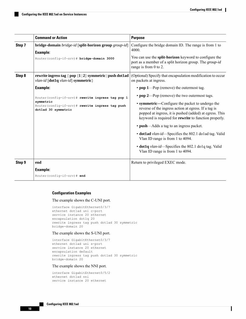
Configure the bridge domain ID. The range is from 1 to4000.
bridge-domain bridge-id [split-horizon group group-id]
Example:
Step 7
You can use the split-horizon keyword to configure theport as a member of a split horizon group. The group-idrange is from 0 to 2.
Router(config-if-srv)# bridge-domain 3000
(Optional) Specify that encapsulation modification to occuron packets at ingress.
rewrite ingress tag { pop {1 | 2} symmetric | push dot1advlan-id [dot1q vlan-id] symmetric}
Step 8
Example: • pop 1—Pop (remove) the outermost tag.
Router(config-if-srv)# rewrite ingress tag pop 1 • pop 2—Pop (remove) the two outermost tags.symmetric • symmetric—Configure the packet to undergo the
reverse of the ingress action at egress. If a tag isRouter(config-if-srv)# rewrite ingress tag pushdot1ad 30 symmetric
popped at ingress, it is pushed (added) at egress. Thiskeyword is required for rewrite to function properly.
• push—Adds a tag to an ingress packet.
• dot1ad vlan-id—Specifies the 802.1 do1ad tag. ValidVlan ID range is from 1 to 4094.
• dot1q vlan-id—Specifies the 802.1 do1q tag. ValidVlan ID range is from 1 to 4094.
Return to privileged EXEC mode.end
Example:
Step 9
Router(config-if-srv)# end
Configuration Examples
The example shows the C-UNI port.interface GigabitEthernet0/3/7ethernet dot1ad uni c-portservice instance 20 ethernetencapsulation dot1q 20rewrite ingress tag push dot1ad 30 symmetricbridge-domain 20
The example shows the S-UNI port.interface GigabitEthernet0/3/7ethernet dot1ad uni s-portservice instance 20 ethernetencapsulation defaultrewrite ingress tag push dot1ad 30 symmetricbridge-domain 20
The example shows the NNI port.interface GigabitEthernet0/5/2ethernet dot1ad nniservice instance 20 ethernet
Configuring IEEE 802.1ad10
Configuring IEEE 802.1adConfiguring the IEEE 802.1ad on Service Instances

encapsulation dot1ad 30bridge-domain 20
Configuring the IEEE 802.1ad on Trunk EFP Service Instances
• Trunk EFP is not supported on S-UNI portsNote
SUMMARY STEPS
1. enable2. configure terminal3. interface interface-id
4. ethernet dot1ad {nni | uni {c-port}}5. service instance [trunk] number ethernet6. encapsulation dot1q7. bridge-domin bridge-id from-encapsulation8. rewrite ingress tag { pop {1 | 2} symmetric9. end
DETAILED STEPS
PurposeCommand or Action
Enables privileged EXEC mode.enableStep 1
Example: • Enter your password if prompted.Router> enable
Enter global configuration mode.configure terminal
Example:
Step 2
Router# configure terminal
Enter interface configuration mode. Valid interfaces arephysical ports.
interface interface-id
Example:
Step 3
Router(config)# interface gigabitethernet0/0/1
Configures Trunk EFP on dot1ad NNI and C-UNI ports onthe interface.
ethernet dot1ad {nni | uni {c-port}}
Example:
Step 4
Trunk EFP is not supported on the S-UNI port.NoteRouter(config-if)# ethernet dot1ad nniorRouter(config-if)# ethernet dot1ad uni c-port
Configure an EFP (service instance) and enter serviceinstance configuration) mode
service instance [trunk] number ethernet
Example:
Step 5
Configuring IEEE 802.1ad11
Configuring IEEE 802.1adConfiguring the IEEE 802.1ad on Trunk EFP Service Instances

PurposeCommand or ActionRouter(config-if)# service instance trunk 1ethernet
• The number is the EFP identifier, an integer from 1 to4000
• The trunk keyword identifies the trunk ID to whichthe service instance is assigned.
Trunk EFP (without port channel) supportsencapsulation of up to 1000 Vlans.
Note
Configure encapsulation type for the service instance.encapsulation dot1qStep 6
Example: • dot1q—Configure 802.1Q encapsulation.Router(config-if-srv)# encapsulation dot1q 10
Configures the router to derive bridge domains from theencapsulation VLAN list.
bridge-domin bridge-id from-encapsulation
Example:
Step 7
Router(config-if-srv)# bridge-domainfrom-encapsulation
(Optional) Specify that encapsulation modification to occuron packets at ingress.
rewrite ingress tag { pop {1 | 2} symmetric
Example:
Step 8
• pop 1—Pop (remove) the outermost tag.Router(config-if-srv)# rewrite ingress tag pop 1symmetric • pop 2—Pop (remove) the two outermost tags.
• symmetric—Configure the packet to undergo thereverse of the ingress action at egress. If a tag ispopped at ingress, it is pushed (added) at egress. Thiskeyword is required for rewrite to function properly.
Return to privileged EXEC mode.end
Example:
Step 9
Router(config-if-srv)# end
Configuration Examples
The example shows the Trunk EFP configuration on the C-UNI port.interface GigabitEthernet0/3/7ethernet dot1ad uni c-portservice instance trunk 20 ethernetencapsulation dot1q 20-30rewrite ingress tag pop1 symmetricbridge-domain from-encapsulation
The example shows the Trunk EFP configuration on the NNI port.interface GigabitEthernet0/5/2ethernet dot1ad nniservice instance trunk 20 ethernetencapsulation dot1ad 20-30
Configuring IEEE 802.1ad12
Configuring IEEE 802.1adConfiguring the IEEE 802.1ad on Trunk EFP Service Instances

rewrite ingress tag pop1 symmetricbridge-domain from-encapsulation
Configuring the IEEE 802.1ad on Cross-Connect on EFP
• The rewrite push command is supported on C-UNI and S-UNI ports. Rewrite is not supported for NNIports.
• Only encapsulation default command is supported on S-UNI ports
Note
SUMMARY STEPS
1. enable2. configure terminal3. interface interface-id
4. ethernet dot1ad {nni | uni {c-port | s-port}}5. service instance number ethernet [name]6. encapsulation {default | dot1q | priority-tagged | untagged}7. rewrite ingress tag push dot1ad vlan-id [dot1q vlan-id] symmetric}8. xconnect peer-router-id vcid pw-class pw-class name
9. end
DETAILED STEPS
PurposeCommand or Action
Enables privileged EXEC mode.enableStep 1
Example: • Enter your password if prompted.Router> enable
Enter global configuration mode.configure terminal
Example:
Step 2
Router# configure terminal
Enter interface configuration mode. Valid interfaces arephysical ports.
interface interface-id
Example:
Step 3
Router(config)# interface gigabitethernet0/0/1
Configures dot1ad NNI, C-port or S-port on the interface.ethernet dot1ad {nni | uni {c-port | s-port}}
Example:
Step 4
Router(config-if)# ethernet dot1ad nniorRouter(config-if)# ethernet dot1ad uni c-portorRouter(config-if)# ethernet dot1ad uni s-port
Configuring IEEE 802.1ad13
Configuring IEEE 802.1adConfiguring the IEEE 802.1ad on Cross-Connect on EFP

PurposeCommand or Action
Configure an EFP (service instance) and enter serviceinstance configuration) mode.
service instance number ethernet [name]
Example:
Step 5
• The number is the EFP identifier, an integer from 1 to4000.
Router(config-if)# service instance 1 Ethernet
• (Optional) ethernet name is the name of a previouslyconfigured EVC. You do not need to use an EVC namein a service instance.
Configure encapsulation type for the service instance.encapsulation {default | dot1q | priority-tagged |untagged}
Step 6
• default—Configure to match all unmatched packets.Example:
• dot1q—Configure 802.1Q encapsulation. See Table 1for details about options for this keyword.Router(config-if-srv)# encapsulation dot1q 10
• priority-tagged—Specify priority-tagged frames,VLAN-ID 0 and CoS value of 0 to 7.
• untagged—Map to untagged VLANs. Only one EFPper port can have untagged encapsulation.
(Optional) Specify that encapsulation modification to occuron packets at ingress.
rewrite ingress tag push dot1ad vlan-id [dot1q vlan-id]symmetric}
Step 7
Example: • symmetric—Configure the packet to undergo thereverse of the ingress action at egress. If a tag is
Router(config-if-srv)# rewrite ingress tag pushdot1ad 30 symmetric
popped at ingress, it is pushed (added) at egress. Thiskeyword is required for rewrite to function properly.
• push—Adds a tag to an ingress packet.
• dot1ad vlan-id—Specifies the 802.1 do1ad tag. ValidVlan ID range is from 1 to 4094.
• dot1q vlan-id—Specifies the 802.1 do1q tag. ValidVlan ID range is from 1 to 4094.
Bind the attachment circuit to a pseudowire virtual circuit(VC) and enter cross connect configuration mode.
xconnect peer-router-id vcid pw-class pw-class name
Example:
Step 8
Router(config-if-srv)# xconnect 10.10.10.10 123encapsulation mpls
Return to privileged EXEC mode.end
Example:
Step 9
Router(config-if-srv)# end
Configuration Examples
The example shows the C-UNI port.
Configuring IEEE 802.1ad14
Configuring IEEE 802.1adConfiguring the IEEE 802.1ad on Cross-Connect on EFP

interface GigabitEthernet0/3/7ethernet dot1ad uni c-portservice instance 20 ethernetencapsulation dot1q 20rewrite ingress tag push dot1ad 30 symmetricxconnect 2.2.2.2 20 encap mpls
The example shows the S-UNI port.
interface GigabitEthernet0/3/7ethernet dot1ad uni s-portservice instance 20 ethernetencapsulation defaultrewrite ingress tag push dot1ad 30 symmetricxconnect 2.2.2.2 20 encap mpls
The example shows the NNI port.
interface GigabitEthernet0/3/7ethernet dot1ad nniservice instance 20 ethernetencapsulation dot1ad 20xconnect 2.2.2.2 20 encap mpls
Verifying IEEE 802.1adUse the show ethernet do1adcommands to verify IEEE 802.1ad configuration.
• show ethernet do1ad
This command displays 802.1ad configuration globally on the router. The following is a sample outputfrom the command:Router# show ethernet dot1ad
Interface: GigabitEthernet0/2/1DOT1AD NNI PortL2protocol pass
Interface: GigabitEthernet0/2/7DOT1AD C-Bridge PortL2protocol pass
• show ethernet do1ad [inteface inteface-name]
This command displays interface dot1ad configuration The following is a sample output from thecommand:Router# show ethernet do1ad interface gigabitethernet 0/2/1
Interface: GigabitEthernet0/2/1DOT1AD NNI PortL2protocol pass
Configuring IEEE 802.1ad15
Configuring IEEE 802.1adVerifying IEEE 802.1ad

Additional ReferencesRelated Documents
Document TitleRelated Topic
Cisco IOS Master Command List , All ReleasesCisco IOS master command list
Standards
TitleStandard
--No new or modified standards are supported, and support for existing standards has not been modified.
MIBs
MIBs LinkMIB
To locate and download MIBs for selected platforms, CiscoIOS releases, and feature sets, use Cisco MIB Locator foundat the following URL:
http://www.cisco.com/go/mibs
No new ormodifiedMIBs are supported, andsupport for existing MIBs has not beenmodified.
RFCs
TitleRFC
--No new or modified RFCs are supported, and support for existing RFCs has not been modified.
Technical Assistance
LinkDescription
http://www.cisco.com/cisco/web/support/index.htmlTheCisco Support andDocumentationwebsite providesonline resources to download documentation, software,and tools. Use these resources to install and configurethe software and to troubleshoot and resolve technicalissues with Cisco products and technologies. Access tomost tools on the Cisco Support and Documentationwebsite requires a Cisco.com user ID and password.
Configuring IEEE 802.1ad16
Configuring IEEE 802.1adAdditional References

Feature Information for IEEE 802.1adThe following table provides release information about the feature or features described in this module. Thistable lists only the software release that introduced support for a given feature in a given software releasetrain. Unless noted otherwise, subsequent releases of that software release train also support that feature.
Use Cisco Feature Navigator to find information about platform support and Cisco software image support.To access Cisco Feature Navigator, go to www.cisco.com/go/cfn. An account on Cisco.com is not required.
Table 4: Feature Information for IEEE 802.1ad
Feature InformationReleasesFeature Name
The IEEE 802.1ad feature supported on service instances andCross Connect on EFPs. This feature was implemented on CiscoASR 900 Series Aggregation Services Routers.
Cisco IOSXERelease 3.13S802.1ad
Configuring IEEE 802.1ad17
Configuring IEEE 802.1adFeature Information for IEEE 802.1ad

Configuring IEEE 802.1ad18
Configuring IEEE 802.1adFeature Information for IEEE 802.1ad
Related Documents