CHAPTER 29-506 Cisco Nexus 7000 Series NX-OS MPLS Configuration Guide OL-23587-01 29 Configuring Ethernet over MPLS Note The Cisco NX-OS release that is running on a managed device may not support all the features or settings described in this chapter. For the latest feature information and caveats, see the documentation and release notes for your platform and software release. This chapter describes how to configure Ethernet Virtual Circuits (EVCs) using the Cisco Data Center Network Manager (DCNM) for Ethernet over Multiprotocol Label Switching (EoMPLS) on Cisco NX-OS devices. This chapter includes the following sections: • Finding Feature Information, page 29-506 • Information About Ethernet over MPLS, page 29-507 • Licensing Requirements for Ethernet over MPLS, page 29-513 • Guidelines and Limitations for Ethernet over MPLS, page 29-513 • Platform Support, page 29-516 • Configuring Ethernet over MPLS, page 29-516 • Verifying the Ethernet over MPLS Configuration, page 29-522 • Monitoring Tunnel Interfaces, page 29-522 • Configuration Examples for Ethernet over MPLS, page 29-523 • Field Descriptions for Tunnel Interfaces, page 29-514 • Additional References, page 29-525 • Feature History for Ethernet Virtual Circuits, page 29-526 Finding Feature Information Your software release might not support all the features documented in this module. For the latest caveats and feature information, see the Bug Search Tool at https://tools.cisco.com/bugsearch/ and the release notes for your software release. To find information about the features documented in this module, and to see a list of the releases in which each feature is supported, see the “New and Changed Information” chapter or the Feature History table below.

Welcome message from author
This document is posted to help you gain knowledge. Please leave a comment to let me know what you think about it! Share it to your friends and learn new things together.
Transcript

Cisco NOL-23587-01
C H A P T E R 29
Configuring Ethernet over MPLSNote The Cisco NX-OS release that is running on a managed device may not support all the features or settings described in this chapter. For the latest feature information and caveats, see the documentation and release notes for your platform and software release.
This chapter describes how to configure Ethernet Virtual Circuits (EVCs) using the Cisco Data Center Network Manager (DCNM) for Ethernet over Multiprotocol Label Switching (EoMPLS) on Cisco NX-OS devices.
This chapter includes the following sections:
• Finding Feature Information, page 29-506
• Information About Ethernet over MPLS, page 29-507
• Licensing Requirements for Ethernet over MPLS, page 29-513
• Guidelines and Limitations for Ethernet over MPLS, page 29-513
• Platform Support, page 29-516
• Configuring Ethernet over MPLS, page 29-516
• Verifying the Ethernet over MPLS Configuration, page 29-522
• Monitoring Tunnel Interfaces, page 29-522
• Configuration Examples for Ethernet over MPLS, page 29-523
• Field Descriptions for Tunnel Interfaces, page 29-514
• Additional References, page 29-525
• Feature History for Ethernet Virtual Circuits, page 29-526
Finding Feature InformationYour software release might not support all the features documented in this module. For the latest caveats and feature information, see the Bug Search Tool at https://tools.cisco.com/bugsearch/ and the release notes for your software release. To find information about the features documented in this module, and to see a list of the releases in which each feature is supported, see the “New and Changed Information” chapter or the Feature History table below.
29-506exus 7000 Series NX-OS MPLS Configuration Guide
Chapter 29 Configuring Ethernet over MPLSInformation About Ethernet over MPLS
Information About Ethernet over MPLSThis section includes the following topics:
• Layer 2 Services, page 29-507
• Ethernet over MPLS, page 29-507
• Attachment Circuits, page 29-507
• Ethernet Virtual Circuits, page 29-508
• Bridge Domain, page 29-508
• Ethernet Flow Point, page 29-508
• Layer 2 VPN Internetworking, page 29-510
• Layer 2 VPN Stateful High Availability, page 29-510
• LinkSec, page 29-511
• MPLS Quality of Service, page 29-512
Layer 2 ServicesA Layer 2 Virtual Private Network (L2VPN) enables service providers to carry multiple network services over a single converged network using Multiprotocol Label Switching (MPLS). MPLS L2VPN extends the Layer 2 domains in data centers. MPLS can be used to connect branch offices to back up data centers and also to interconnect multiple data centers in the same organization.
L2VPN services using the MPLS/IP core can be divided into two categories: wire and LAN services. The Virtual Private Wire Service (VPWS) provides point-to-point service between two customer edge (CE) devices over the provider core. The Virtual Private LAN Service (VPLS) provides point-to-multipoint service between multiple customer sites using a mesh of point-to-point pseudowires over the provider core to emulate a LAN between the sites.
Ethernet over MPLSEthernet over MPLS (EoMPLS) is a VPWS service that is used to carry Layer 2 Ethernet frames over an MPLS network. EoMPLS enables service providers to offer emulated Ethernet services over existing MPLS networks.
EoMPLS encapsulates Ethernet frames in MPLS packets and forwards them across the MPLS network. Each frame is transported as a single packet, and the PE routers connected to the backbone add and remove labels as appropriate for packet encapsulation. Using EoMPLS, Layer 2 networks that are geographically separated can be connected without requiring bridges or routers at the remote locations.
Attachment CircuitsA Layer 2 circuit that connects a customer edge (CE) node to a provider edge (PE) node is known as an attachment circuit or AC. A Layer 2 VPN (L2VPN) supports only Ethernet ACs on Cisco NX-OS devices.
29-507Cisco Nexus 7000 Series NX-OS MPLS Configuration Guide
OL-23587-01
Chapter 29 Configuring Ethernet over MPLSInformation About Ethernet over MPLS
To cross the network core, the Layer 2 traffic is tunneled inside a pseudowire. A pseudowire is typically a Multiprotocol Label Switching (MPLS) label-switched path (LSP), or a Layer 2 Tunneling Protocol (L2TP) tunnel, or the psuedowire can be locally switched from another AC. Layer 2 VPN connects different types of circuits (that is, different types of Layer 2 ACs and pseudowires) together in different ways to implement different types of end-to-end services.
The following types of ACs are supported:
• Ethernet port mode—This AC includes all frames that are sent and received on a physical Ethernet port.
• Ethernet 802.1Q—This AC includes all frames that are sent and received with a particular VLAN tag.
• Ethernet 802.1ad (Q-in-Q)—This AC includes all frames that are sent and received with a specific outer VLAN tag and a specific inner VLAN tag. VLAN-in-VLAN (Q-in-Q) is supported only in the service instance configuration and not in the subinterface configuration.
• Ethernet QinAny—This AC includes all frames that are sent and received with a specific outer VLAN tag and any inner VLAN tags, as long as the inner VLAN tag is not used on another subinterface.
Ethernet Virtual CircuitsAn Ethernet Virtual Circuit (EVC) as defined by the Metro Ethernet Forum is a port-level point-to-point or multipoint-to-multipoint Layer 2 circuit. It is an end-to-end representation of a single instance of a Layer 2 service being offered by a provider to a customer.
Bridge DomainA bridge domain is a generic object that represents a Layer 2 broadcast domain on a device. The EVC architecture uses a bridge domain to define a Layer 2 multipoint service.
Creating a bridge domain also creates the underlying VLAN, if it does not already exist. There is a one-to-one mapping of bridge domains to VLANs; bridge domain 100 maps to VLAN 100.
Ethernet Flow PointAn Ethernet Flow Point (EFP) is the instantiation of an EVC on a specific interface on a device. The EFP interface representation is similar to that of a subinterface that maintains the parent-child relationship with the port.
The EFP interface is a Layer 2 logical interface. Any Layer 2 feature, protocol, or application that functions on a switchport is equally applicable to an EFP, although some constraints might apply. Similar to a physical port, the interface state machine and forwarding behavior for the EFP depends on the service to which it belongs.
An EFP interface, also known as a service instance, is implicitly created when you configure an Ethernet service instance on a port. An EFP can be configured under a physical or logical parent port. Each service instance has its own configuration submode. Different features that apply to the service instance can be configured in that submode.
29-508Cisco Nexus 7000 Series NX-OS MPLS Configuration Guide
OL-23587-01
Chapter 29 Configuring Ethernet over MPLSInformation About Ethernet over MPLS
Because a single parent port can support multiple service instances, several EFPs can be associated with the port, with each EFP as part of a different EVC. For this reason, whenever a service instance is configured on a port, the port is internally brought up in trunk mode.
Note The EVC represents a bridge domain. An EFP is an instance of an Ethernet flow on a particular interface that belongs to a bridge domain. The Ethernet flow, not the entire port, belongs to the bridge domain.
Flow per EFP
A trunk is a point-to-point link between the switch and another networking device. Trunks carry the traffic of multiple VLANs over a single link and allow you to extend VLANs across an entire network. EVCs can identify flows based on multiple criteria in the Layer 2 header. In Cisco NX-OS, the flow identification for devices with Enhanced Logic recognition Logic 8 (Earl8) hardware is based on matching the VLAN tag of the incoming packet. If the incoming packet has multiple VLAN tags, only the outer tag is used for traffic mapping to an EFP.
To correctly deliver the traffic on a trunk port with several VLANs, the device uses the IEEE 802.1Q encapsulation, or tagging method, that uses a tag that is inserted into the frame header. This tag carries information about the specific VLAN to which the frame and packet belong. This method allows packets that are encapsulated for several different VLANs to traverse the same port and maintain traffic separation between the VLANs. Also, the encapsulated VLAN tag allows the trunk to move traffic end-to-end through the network on the same VLAN.
Encapsulation defines the matching criteria that maps a VLAN to the service instance. A single VLAN ID can be configured for an exact match of the outermost tag. Any VLAN ID that is not specifically configured on an EFP or subinterface is treated as if it is implicitly configured for default encapsulation. On a parent port, you can configure either a single default EFP or one or more EFPs with explicit encapsulation, but not both.
VLAN Translations
VLAN translation, also know as a rewrite operation, provides flexibility in managing virtual LANs (VLANs) and Metro Ethernet-related services. VLAN translation is supported for Ethernet interfaces only, not for other types of interfaces.
With 1:1 VLAN translation, the VLAN of the incoming traffic (CE VLAN) is rewritten (replaced) by a provider edge (PE) VLAN. This process enables the service provider to address the situation where incoming traffic from two different customers share the same customer edge (CE) VLAN. The service provider can map the two CE VLANs to two different PE VLANs, and customer traffic will not be mixed.
Devices can also push (add) or pop (remove) VLAN tags in frame headers. A VLAN tag push is supported only on a service instance that is configured as the default EFP. In order to push a VLAN tag, the port mode is implicitly changed to a tunnel, making the port unable to distinguish the incoming flow based on VLAN tags. A VLAN tag is pushed for every frame that enters the port, irrespective of the incoming VLAN tag. In port mode, a VLAN tag is pushed at ingress and the same tag is popped at the egress to apply symmetric rewrites on an EFP.
29-509Cisco Nexus 7000 Series NX-OS MPLS Configuration Guide
OL-23587-01
Chapter 29 Configuring Ethernet over MPLSInformation About Ethernet over MPLS
Layer 2 VPN InternetworkingLayer 2 transport over Multiprotocol Label Switching (MPLS) already exists for like-to-like attachment circuits, such as Ethernet-to-Ethernet. Layer 2 Virtual Private Network (L2VPN) internetworking builds on this functionality by allowing disparate attachment circuits to be connected. The internetworking function facilitates the translation between the different Layer 2 encapsulations.
The EoMPLS L2VPN Internetworking feature supports Ethernet and VLAN attachment circuits over MPLS. The features and restrictions for like-to-like functionality also apply to L2VPN internetworking.
For more information, see the “Configuring Any Transport over MPLS” chapter.
Layer 2 VPN Stateful High AvailabilityThe L2VPN Stateful High Availability (HA) feature uses two supervisor modules to provide uninterrupted service during a system failure. This implementation is the same for both Ethernet over Multiprotocol Label Switching (EoMPLS) and Virtual Private LAN Service (VPLS). During a failure, when an active supervisor is down, the standby supervisor seamlessly takes over all operations without disruptions. The supervisor modules also use Nonstop Forwarding (NSF), Stateful Switchover (SSO), and Graceful Restart (GR) for Any Transport over MPLS (AToM) to recover from an interruption in the service.
Peer Label Switch Routers (LSRs) exchange label binding information in an Multiprotocol Label Switching (MPLS) network to support the forwarding process. The MPLS Label Distribution Protocol Graceful Restart feature provides a mechanism by which the forwarding state between LSRs can be maintained during interruptions such as SSO failover events and temporary loss of Label Distribution Protocol (LDP) communication between the LSRs to enable NSF for MPLS traffic.
To enable NSF for Any Transport over MPLS (AToM) traffic, the provider edge (PE) devices and the LDP peers involved in the SSO event must support GR. There is no specific configuration required for Layer 2 VPN stateful HA.
Ethernet over MPLS CoexistenceThis section includes the following topics. There are no specific tasks required to configure these features:
• Ethernet over Multiprotocol Label Switching and Virtual Private LAN Service, page 29-510
• Ethernet over MPLS and Cisco Overlay Transport Virtualization, page 29-511
• Ethernet over MPLS and Virtual Private Lan Service, page 29-511
Ethernet over Multiprotocol Label Switching and Virtual Private LAN Service
Ethernet over Multiprotocol Label Switching (EoMPLS) and Virtual Private LAN Service (VPLS) can coexist with MPLS Layer 3 VPNs (L3VPNs) on the same device. When you use a routed pseudowire, EoMPLS is configured on a bridge domain or a VLAN and the switched virtual interface (SVI) for that VLAN participates in Layer 3 forwarding or is part of a virtual routing and forwarding (VRF) instance. You can also configure a routed pseudowire by adding the pseudowire directly to a bridge domain. Adding a pseudowire directly to a bridge domain is not supported on all Cisco Nexus platforms. If this configuration is not supported, and VPLS is already configured on the device, the Layer 3 configuration on the SVI is rejected and vice versa.
29-510Cisco Nexus 7000 Series NX-OS MPLS Configuration Guide
OL-23587-01
Chapter 29 Configuring Ethernet over MPLSInformation About Ethernet over MPLS
Pseudowires enable payloads to be transparently carried across IP or MPLS packet-switched networks (PSNs). This functionality provides a Layer 3 virtual interface representation of a pseudowire on a provider edge (PE) device. This functionality also allows the backhaul of customer packets over pseudowires and the application of Layer 3 features, such as quality of service (QoS) policing and shaping, and access lists on customer packets.
A pseudowire head end allows a pseudowire to be terminated on a VRF instance; however, this termination is not required for EoMPLS co-existence.
Ethernet over MPLS and Cisco Overlay Transport Virtualization
If Ethernet over Multiprotocol Label Switching (EoMPLS) and Cisco Overlay Transport Virtualization (OTV) are configured on different bridge domains or VLANs, they can coexist on the same device. If EoMPLS and OTV coexist on a device, one part of the network uses MPLS EoMPLS and the other part uses OTV. The Provider Edge Gateway (PE-G) forwards packets between these two parts of the network. The IP (OTV) cloud and the MPLS cloud can be the same physical network. In OTV, MAC-address learning occurs in the control plane and in EoMPLS, it occurs in the data plane.
Ethernet over MPLS and Virtual Private Lan Service
Ethernet over Multiprotocol Label Switching (EoMPLS) can coexist with Virtual Private LAN Service (VPLS) on the same device because EoMPLS is configured on interfaces and VPLS is configured on a bridge domain. Point-to-point EoMPLS and VPLS can also coexist on the same device.
In EoMPLS port-mode operation, an attachment circuit (AC) cannot be part of a bridge domain of a VPLS because all incoming tagged packets are tunneled through a pseudowire. In EoMPLS VLAN mode operation, a packet with a matching VLAN is sent over a point-to-point pseudowire. Packets with other VLANs are mapped to a bridge domain and hence, these packets can participate in VPLS forwarding.
LinkSecThe LinkSec feature provides security for data centers over pseudowires using point-to-point encryption. LinkSec supports IEEE 802.1AE link-layer cryptography that provides hop-by-hop security of data in the MAC layer. Link-layer cryptography helps ensure end-to-end data privacy while enabling the insertion of security service devices along the encrypted path.
Hop-by-Hop Encryption
In this type of deployment, data is encrypted on the egress interface of the device and decrypted on the ingress interface of the device. Data is encrypted while being transmitted on interfaces but decrypted inside devices. However, if LinkSec is unavailable on certain segments of the network, data is sent in decrypted state on these segments. The advantage of this type of deployment is that Layer 2 Virtual Private Network (L2VPN) or Multiprotocol Label Switching (MPLS) is not aware of the encryption.
Hop-by-hop encryption is the default mode of encryption in LinkSec.
29-511Cisco Nexus 7000 Series NX-OS MPLS Configuration Guide
OL-23587-01
Chapter 29 Configuring Ethernet over MPLSInformation About Ethernet over MPLS
Encryption and Decryption at Customer Edge Devices
After Layer 2 Virtual Private Network (L2VPN) or Multiprotocol Label Switching (MPLS) has added its label information to the frame, LinkSec encrypts both the data packet and the VLAN tag. The VLAN tag is lost and LinkSec sends the entire package across the network as payload. In this type of deployment, data is encrypted and decrypted at customer edge (CE) devices only.
To enable this deployment, you should configure the provider edge (PE) ports in the port mode of L2VPN operation because the VLAN tag is lost during LinkSec encryption.
This method can also be deployed by configuring the PE ports as access switchports and mapping the packets that enter the ingress PE1 interface to an access VLAN. The packets are then forwarded using Virtual Private Lan Service (VPLS) or Ethernet over Multiprotocol Label Switching (EoMPLS) if the egress PE1 interface is configured to be part of a bridge domain of the VLAN.
MPLS Quality of ServiceTo maintain the quality of service (QoS) when a packet traverses both Layer 2 and Layer 3 domains, the type of service (ToS) and CoS values must be mapped to each other. CoS refers to three bits in either an Inter-Switch Link (ISL) header or an 802.1Q header that are used to indicate the priority of an Ethernet frame as it passes through a switched network.
The 802.1Q provides QoS-based matching and marking to VLAN user priority bits to provide QoS on the Gigabit Ethernet WAN interface for 802.1Q packets. Packet marking helps identify packet flows. Packet marking enables the partitioning of a network into multiple priority levels or CoS. During network congestion, packets that are marked as priority are offered a higher priority than other packets.
802.1Q input packets are classified at eight different QoS levels (0 to 7) based on the VLAN user priority bits. For 802.1Q output packets, QoS marking is done at the VLAN header to modify VLAN user priority bits. QoS services use these priority bit settings to gain traffic priority during network congestion.
Experimental Bits
EXP is a 3-bit field and part of a Multiprotocol Label Switching (MPLS) header. Experimental (EXP) bits in an MPLS header carry the priority of packets. Each label switching device along the network path honors the packet priority by queuing packets in the proper queue and servicing packets according to the priority. EXP bits define the quality of service (QoS) treatment (per-hop behavior) that a node should give to a packet. It is the equivalent of the differentiated service code point (DSCP) in the IP network. A DSCP defines a class and drop precedence. The EXP bits generally carry all information encoded in IP DSCP. However, in some cases, the EXP bits are used exclusively to encode the dropping precedence.
QoS on a Layer 2 VPN (L2VPN) network usually has two parts, an attachment circuit (AC) side and a pseudowire side. Layer 2 QoS is applied on the AC side and Layer 3 MPLS or IP QoS is applied on the pseudowire side.
Virtual Private LAN Service (VPLS) QoS is similar to Ethernet over MPLS (EoMPLS) QoS, except that QoS in VPLS is applied at ACs that participate in a VPLS bridge domain.
The core-facing MPLS interface must support a QoS policy. This QoS policy is applied on Ethernet Virtual Circuits (EVCs) and switchport interfaces. If a switchport interface participates in QoS handling, the matching criteria must include the VLAN on which VPLS forwarding is configured.
Setting the EXP bit value helps service providers who do not want to modify the value of the IP precedence field within the IP packets that are transported through their networks. By choosing different values for the Multiprotocol Label Switching (MPLS) EXP bit field, you can specify the priority that a packet requires during periods of network congestion. By default, the IP precedence value is copied into
29-512Cisco Nexus 7000 Series NX-OS MPLS Configuration Guide
OL-23587-01
Chapter 29 Configuring Ethernet over MPLSLicensing Requirements for Ethernet over MPLS
the MPLS EXP field during imposition. On the imposition path, packets are received from the AC and are sent to the MPLS core. You can specify the MPLS EXP bits with an MPLS quality of service (QoS) policy.
By default, EXP is derived from COS for VPLS and VLAN-based EoMPLS. For port-based EoMPLS, by default, EXP is derived from the DSCP value.
Licensing Requirements for Ethernet over MPLSThe following table shows the licensing requirements for this feature:
Prerequisites• MPLS must be configured in the core so that a label-switched path (LSP) exists between the provider
edge (PE) devices.
• Cisco Express Forwarding must be enabled before you configure any Layer 2 circuits.
Guidelines and Limitations for Ethernet over MPLSEthernet over MPLS (EoMPLS) has the following guidelines and limitations:
• Fabric Extender (FEX) ports are not supported as members of either XConnect or virtual forwarding instance (VFI) contexts.
• EoMPLS and VPLS can coexist on the same device.
• EoMPLS and VPLS can coexist with MPLS Layer 3 VPNs on the same device.
• If EoMPLS and Cisco Overlay Transport Virtualization (OTV) are configured on different bridge domains or VLANs, they can coexist on the same device.
• The load balancing method required in the Layer 2 VPN is different from the Layer 3 VPN. Layer 3 VPN and Layer 2 VPN forwarding are performed independently on the device using two different types of adjacencies; therefore, the forwarding is not impacted by having a different method of load balancing for the Layer 2 VPN.
• Starting from Cisco NX-OS Release 8.2(1), all EoMPLS functionalities, except Ethernet Flow Points (EFP), Service Instances and Bridge Domains, are supported on M3-Series I/O modules.
• Starting from Cisco NX-OS Release 8.4(1), all EoMPLS functionalities, except Ethernet Flow Points (EFP), Service Instances and Bridge Domains, are supported on F4-Series I/O modules.
EVCs have the following configuration guidelines and limitations:
• EFPs can be created only on Layer 3 interfaces without a switchport or IP address configuration.
Product License Requirement
Cisco DCNM IP tunnels require a LAN Enterprise license. For a complete explanation of the DCNM licensing scheme and how to obtain and apply licenses, see the Cisco DCNM Installation and Licensing Guide, Release 5.x.
Cisco NX-OS Layer 2 MVPNs require an MPLS license. For a complete explanation of the Cisco NX-OS licensing scheme and how to obtain and apply licenses, see the Cisco NX-OS Licensing Guide.
29-513Cisco Nexus 7000 Series NX-OS MPLS Configuration Guide
OL-23587-01
Chapter 29 Configuring Ethernet over MPLSField Descriptions for Tunnel Interfaces
• EFPs are not supported on subinterfaces.
• The total number of EFPs and subinterfaces that are supported in a system is 4000.
• The following features are not supported:
– Service instance (Ethernet flow point [EFP]) group support.
– EVC cross-connect and connect forwarding services.
– Ethernet service protection features such as Ethernet Operations, Administration, and Maintenance (EOAM), Connectivity Fault Management (CFM), or Ethernet Local Management Interface (E-LMI).
– Access control lists (ACLs).
Layer 2 VPN internetworking has the following configuration guidelines and limitations:
• Ethernet interworking for a raw Ethernet port or a VLAN trunk is not supported. Traffic streams are not kept separate when traffic is sent between transport types.
• The following restrictions apply to Layer 2 VPN internetworking and VLAN:
– There must be a one-to-one relationship between an attachment circuit and the pseudowire. Point-to-multipoint or multipoint-to-point configurations are not supported.
– The routing protocols for point-to-point operation on the customer edge (CE) devices must be configured when configuring an Ethernet to a non-Ethernet setup.
– The Ethernet or VLAN must contain only two IP devices: the PE device and the CE device. The PE device performs proxy Address Resolution Protocol (ARP) and responds to all ARP requests that it receives. Therefore, only one CE and one PE device should be on the Ethernet or VLAN segment.
– When you change the interworking configuration on an Ethernet PE device, clear the ARP entry on the adjacent CE device so that it can learn the new MAC address. Otherwise, you might experience traffic drops.
• The following restriction applies if you configure Layer 2 VPN internetworking between Ethernet and VLAN with Cisco Catalyst switches as the CE devices:
– The Spanning Tree Protocol (STP) is supported for Ethernet interworking. Ethernet interworking between an Ethernet port and a VLAN supports STP only on VLAN 1. Configure VLAN 1 as a non native VLAN.
Field Descriptions for Tunnel InterfacesThis section includes the following field descriptions for tunnel interfaces:
• Tunnel: Details Tab: Tunnel Details Section, page 29-515
• Tunnels: Details Tab: Source Section, page 29-515
• Tunnel: Statistics Tab, page 29-515
29-514Cisco Nexus 7000 Series NX-OS MPLS Configuration Guide
OL-23587-01
Chapter 29 Configuring Ethernet over MPLSField Descriptions for Tunnel Interfaces
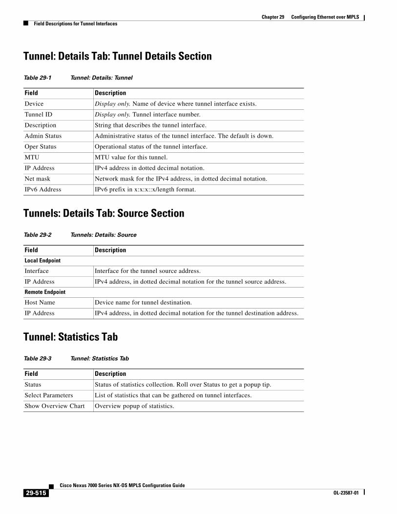
Tunnel: Details Tab: Tunnel Details Section
Tunnels: Details Tab: Source Section
Tunnel: Statistics Tab
Table 29-1 Tunnel: Details: Tunnel
Field Description
Device Display only. Name of device where tunnel interface exists.
Tunnel ID Display only. Tunnel interface number.
Description String that describes the tunnel interface.
Admin Status Administrative status of the tunnel interface. The default is down.
Oper Status Operational status of the tunnel interface.
MTU MTU value for this tunnel.
IP Address IPv4 address in dotted decimal notation.
Net mask Network mask for the IPv4 address, in dotted decimal notation.
IPv6 Address IPv6 prefix in x:x:x::x/length format.
Table 29-2 Tunnels: Details: Source
Field Description
Local Endpoint
Interface Interface for the tunnel source address.
IP Address IPv4 address, in dotted decimal notation for the tunnel source address.
Remote Endpoint
Host Name Device name for tunnel destination.
IP Address IPv4 address, in dotted decimal notation for the tunnel destination address.
Table 29-3 Tunnel: Statistics Tab
Field Description
Status Status of statistics collection. Roll over Status to get a popup tip.
Select Parameters List of statistics that can be gathered on tunnel interfaces.
Show Overview Chart Overview popup of statistics.
29-515Cisco Nexus 7000 Series NX-OS MPLS Configuration Guide
OL-23587-01
Chapter 29 Configuring Ethernet over MPLSPlatform Support
Platform SupportThe following platform supports this feature. For platform-specific information, including guidelines and limitations, system defaults, and configuration limits, see the corresponding documentation.
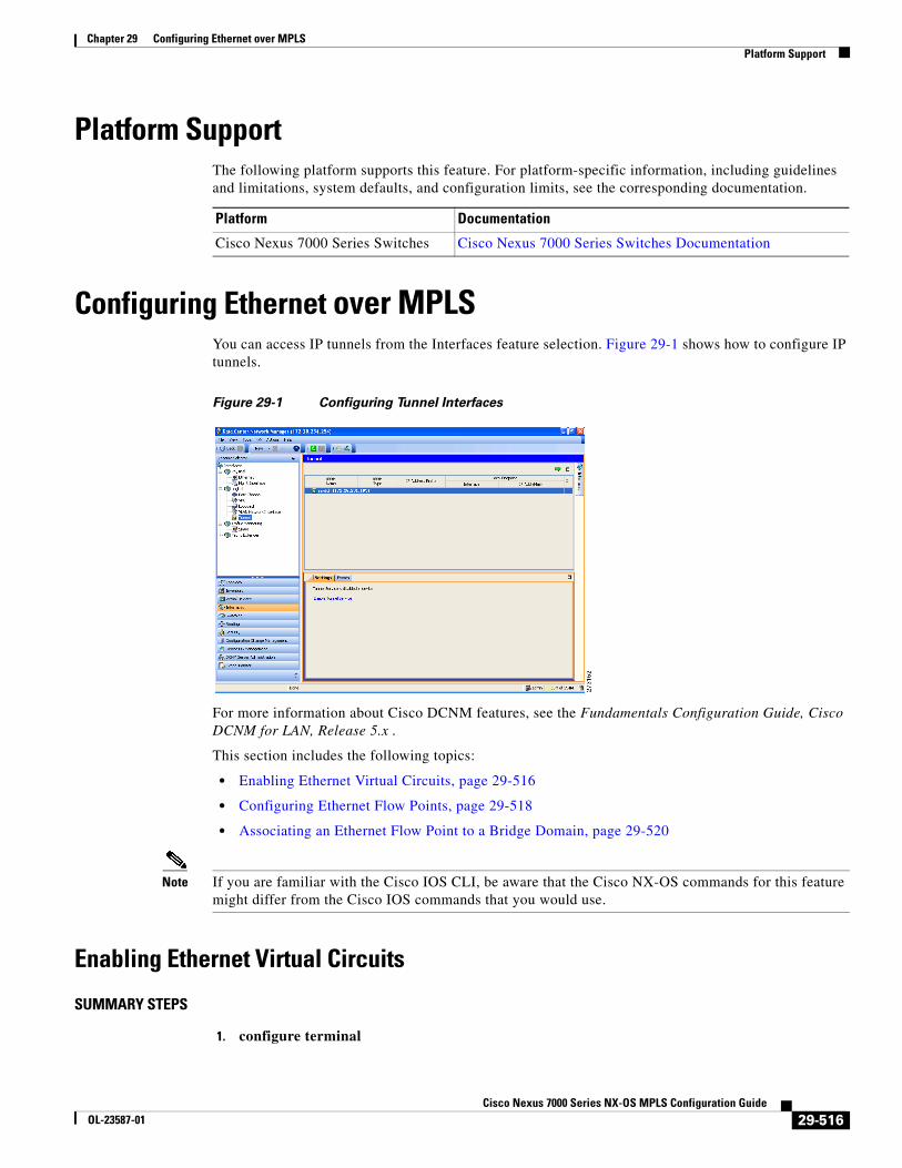
Configuring Ethernet over MPLSYou can access IP tunnels from the Interfaces feature selection. Figure 29-1 shows how to configure IP tunnels.
Figure 29-1 Configuring Tunnel Interfaces
For more information about Cisco DCNM features, see the Fundamentals Configuration Guide, Cisco DCNM for LAN, Release 5.x .
This section includes the following topics:
• Enabling Ethernet Virtual Circuits, page 29-516
• Configuring Ethernet Flow Points, page 29-518
• Associating an Ethernet Flow Point to a Bridge Domain, page 29-520
Note If you are familiar with the Cisco IOS CLI, be aware that the Cisco NX-OS commands for this feature might differ from the Cisco IOS commands that you would use.
Enabling Ethernet Virtual Circuits
SUMMARY STEPS
1. configure terminal
Platform Documentation
Cisco Nexus 7000 Series Switches Cisco Nexus 7000 Series Switches Documentation
29-516Cisco Nexus 7000 Series NX-OS MPLS Configuration Guide
OL-23587-01
Chapter 29 Configuring Ethernet over MPLSConfiguring Ethernet over MPLS
2. feature evc
3. exit
4. (Optional) show feature
5. (Optional) copy running-config startup-config
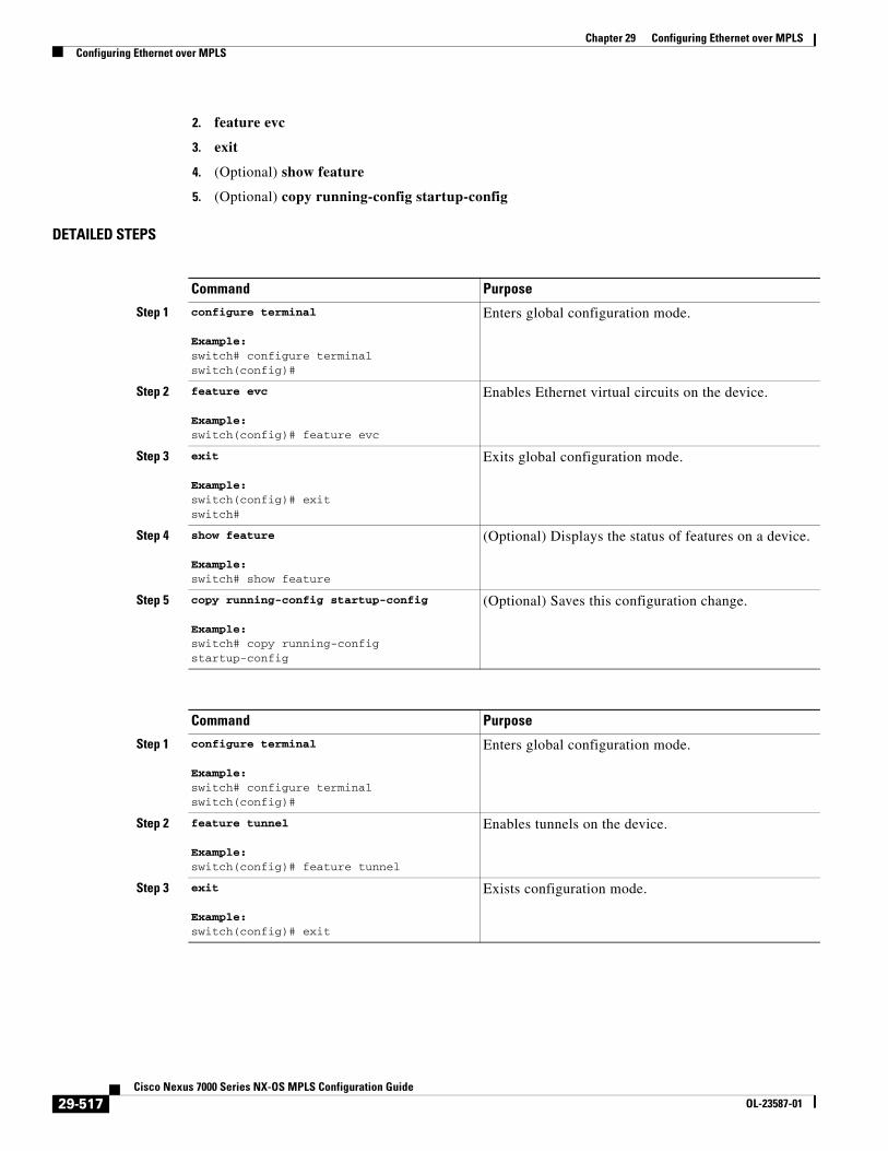
DETAILED STEPS
Command Purpose
Step 1 configure terminal
Example:switch# configure terminalswitch(config)#
Enters global configuration mode.
Step 2 feature evc
Example:switch(config)# feature evc
Enables Ethernet virtual circuits on the device.
Step 3 exit
Example:switch(config)# exit switch#
Exits global configuration mode.
Step 4 show feature
Example:switch# show feature
(Optional) Displays the status of features on a device.
Step 5 copy running-config startup-config
Example:switch# copy running-config startup-config
(Optional) Saves this configuration change.
Command Purpose
Step 1 configure terminal
Example:switch# configure terminalswitch(config)#
Enters global configuration mode.
Step 2 feature tunnel
Example:switch(config)# feature tunnel
Enables tunnels on the device.
Step 3 exit
Example:switch(config)# exit
Exists configuration mode.
29-517Cisco Nexus 7000 Series NX-OS MPLS Configuration Guide
OL-23587-01
Chapter 29 Configuring Ethernet over MPLSConfiguring Ethernet over MPLS
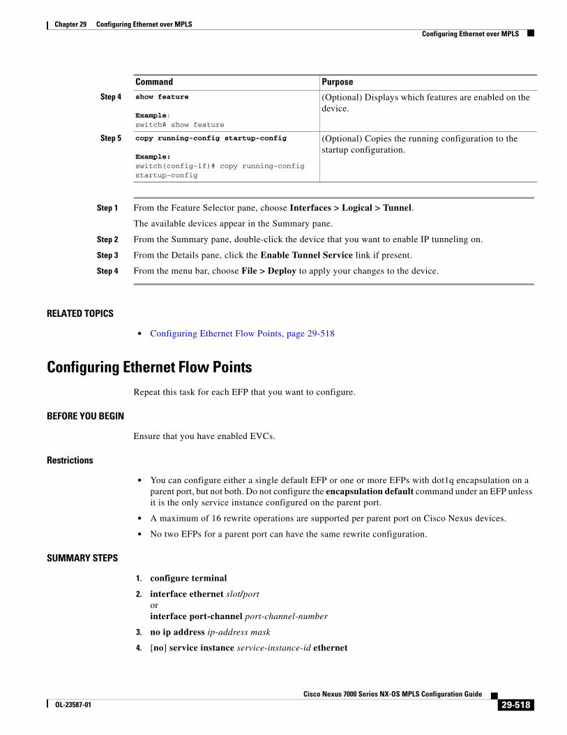
Step 1 From the Feature Selector pane, choose Interfaces > Logical > Tunnel.
The available devices appear in the Summary pane.
Step 2 From the Summary pane, double-click the device that you want to enable IP tunneling on.
Step 3 From the Details pane, click the Enable Tunnel Service link if present.
Step 4 From the menu bar, choose File > Deploy to apply your changes to the device.
RELATED TOPICS
• Configuring Ethernet Flow Points, page 29-518
Configuring Ethernet Flow PointsRepeat this task for each EFP that you want to configure.
BEFORE YOU BEGIN
Ensure that you have enabled EVCs.
Restrictions
• You can configure either a single default EFP or one or more EFPs with dot1q encapsulation on a parent port, but not both. Do not configure the encapsulation default command under an EFP unless it is the only service instance configured on the parent port.
• A maximum of 16 rewrite operations are supported per parent port on Cisco Nexus devices.
• No two EFPs for a parent port can have the same rewrite configuration.
SUMMARY STEPS
1. configure terminal
2. interface ethernet slot/portorinterface port-channel port-channel-number
3. no ip address ip-address mask
4. [no] service instance service-instance-id ethernet
Step 4 show feature
Example:switch# show feature
(Optional) Displays which features are enabled on the device.
Step 5 copy running-config startup-config
Example:switch(config-if)# copy running-config startup-config
(Optional) Copies the running configuration to the startup configuration.
Command Purpose
29-518Cisco Nexus 7000 Series NX-OS MPLS Configuration Guide
OL-23587-01
Chapter 29 Configuring Ethernet over MPLSConfiguring Ethernet over MPLS
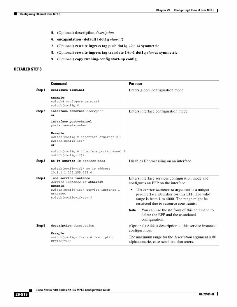
5. (Optional) description description
6. encapsulation {default | dot1q vlan-id}
7. (Optional) rewrite ingress tag push dot1q vlan-id symmetric
8. (Optional) rewrite ingress tag translate 1-to-1 dot1q vlan-id symmetric
9. (Optional) copy running-config start-up config
DETAILED STEPS
Command Purpose
Step 1 configure terminal
Example:switch# configure terminalswitch(config)#
Enters global configuration mode.
Step 2 interface ethernet slot/port
or
interface port-channel port-channel-number
Example:switch(config)# interface ethernet 2/1switch(config-if)#
or
switch(config)# interface port-channel 1switch(config-if)#
Enters interface configuration mode.
Step 3 no ip address ip-address mask
switch(config-if)# no ip address 10.1.1.1 255.255.255.0
Disables IP processing on an interface.
Step 4 [no] service instance service-instance-id ethernet Example:switch(config-if)# service instance 1 ethernet switch(config-if-srv)#
Enters interface services configuration mode and configures an EFP on the interface.
• The service-instance-id argument is a unique per-interface identifier for this EFP. The valid range is from 1 to 4000. The range might be restricted due to resource constraints.
Note You can use the no form of this command to delete the EFP and the associated configuration.
Step 5 description description
Example:switch(config-if-srv)# description EFP1forTest
(Optional) Adds a description to this service instance configuration.
The maximum range for the description argument is 80 alphanumeric, case-sensitive characters.
29-519Cisco Nexus 7000 Series NX-OS MPLS Configuration Guide
OL-23587-01
Chapter 29 Configuring Ethernet over MPLSConfiguring Ethernet over MPLS
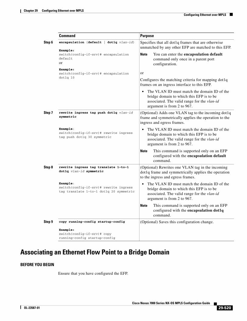
Associating an Ethernet Flow Point to a Bridge Domain
BEFORE YOU BEGIN
Ensure that you have configured the EFP.
Step 6 encapsulation {default | dot1q vlan-id}
Example:switch(config-if-srv)# encapsulation default
or
Example:switch(config-if-srv)# encapsulation dot1q 10
Specifies that all dot1q frames that are otherwise unmatched by any other EFP are matched to this EFP.
Note You can enter the encapsulation default command only once in a parent port configuration.
or
Configures the matching criteria for mapping dot1q frames on an ingress interface to this EFP.
• The VLAN ID must match the domain ID of the bridge domain to which this EFP is to be associated. The valid range for the vlan-id argument is from 2 to 967.
Step 7 rewrite ingress tag push dot1q vlan-id symmetric
Example:switch(config-if-srv)# rewrite ingress tag push dot1q 30 symmetric
(Optional) Adds one VLAN tag to the incoming dot1q frame and symmetrically applies the operation to the ingress and egress frames.
• The VLAN ID must match the domain ID of the bridge domain to which this EFP is to be associated. The valid range for the vlan-id argument is from 2 to 967.
Note This command is supported only on an EFP configured with the encapsulation default command.
Step 8 rewrite ingress tag translate 1-to-1 dot1q vlan-id symmetric
Example:switch(config-if-srv)# rewrite ingress tag translate 1-to-1 dot1q 20 symmetric
(Optional) Rewrites one VLAN tag in the incoming dot1q frame and symmetrically applies the operation to the ingress and egress frames.
• The VLAN ID must match the domain ID of the bridge domain to which this EFP is to be associated. The valid range for the vlan-id argument is from 2 to 967.
Note This command is supported only on an EFP configured with the encapsulation dot1q command.
Step 9 copy running-config startup-config
Example:switch(config-if-srv)# copy running-config startup-config
(Optional) Saves this configuration change.
Command Purpose
29-520Cisco Nexus 7000 Series NX-OS MPLS Configuration Guide
OL-23587-01
Chapter 29 Configuring Ethernet over MPLSConfiguring Ethernet over MPLS
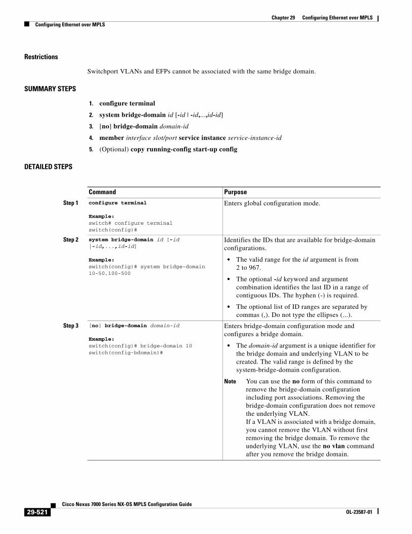
Restrictions
Switchport VLANs and EFPs cannot be associated with the same bridge domain.
SUMMARY STEPS
1. configure terminal
2. system bridge-domain id [-id | -id,...,id-id]
3. [no] bridge-domain domain-id
4. member interface slot/port service instance service-instance-id
5. (Optional) copy running-config start-up config
DETAILED STEPS
Command Purpose
Step 1 configure terminal
Example:switch# configure terminalswitch(config)#
Enters global configuration mode.
Step 2 system bridge-domain id [-id |-id,...,id-id]
Example:switch(config)# system bridge-domain 10-50,100-500
Identifies the IDs that are available for bridge-domain configurations.
• The valid range for the id argument is from 2 to 967.
• The optional -id keyword and argument combination identifies the last ID in a range of contiguous IDs. The hyphen (-) is required.
• The optional list of ID ranges are separated by commas (,). Do not type the ellipses (...).
Step 3 [no] bridge-domain domain-id
Example:switch(config)# bridge-domain 10switch(config-bdomain)#
Enters bridge-domain configuration mode and configures a bridge domain.
• The domain-id argument is a unique identifier for the bridge domain and underlying VLAN to be created. The valid range is defined by the system-bridge-domain configuration.
Note You can use the no form of this command to remove the bridge-domain configuration including port associations. Removing the bridge-domain configuration does not remove the underlying VLAN. If a VLAN is associated with a bridge domain, you cannot remove the VLAN without first removing the bridge domain. To remove the underlying VLAN, use the no vlan command after you remove the bridge domain.
29-521Cisco Nexus 7000 Series NX-OS MPLS Configuration Guide
OL-23587-01

Chapter 29 Configuring Ethernet over MPLSVerifying the Ethernet over MPLS Configuration
Verifying the Ethernet over MPLS ConfigurationTo verify EoMPLS configuration information, perform one of the following tasks:
Monitoring Tunnel InterfacesYou can configure DCNM to collect tunnel interface statistics. Choose Interfaces > Logical > Tunnel from the Feature Selector and navigate to the interface that you want to collect statistics on.
You see the Port Traffic Statistics window. You can collect statistics on input and output (packet and byte) counters, broadcast, multicast, and unicast traffic.
Step 4 member interface slot/port service instance service-instance-id
Example:switch(config-bdomain)# member ethernet 2/1 service instance 1
Binds a service instance to this bridge domain.
• The interface slot/port argument identifies the interface under which the service instance is configured.
• The service-instance-id argument identifies the service instance to be bound. The valid range is from 1 to 4000.
Step 5 copy running-config startup-config
Example:switch(config-bdomain)# copy running-config startup-config
(Optional) Saves this configuration change.
Command Purpose
Command Purpose
show bridge-domain Displays information about bridge domains that are configured on the device.
show ethernet service instance [detail] Displays information about service instances that are configured on the device.
show ethernet service instance interface ethernet slot/port [detail]
Displays information about service instances that are configured on an interface.
show ethernet service instance id service-instance-id interface ethernet slot/port [detail]
Displays information about a specific service instance that is configured on an interface.
show interface description Displays a description for interfaces.
show interface ethernet Displays interface status and information.
show interface ethernet slot/port brief Displays brief information about the interface.
show interface ethernet slot/port counters Displays in and out counters for the interface.
show interface status Displays the interface line status.
show l2vpn service all detail Displays information about Layer 2 VPN services.
show vlan bridge-domain-id Displays EFPs associated with a bridge domain.
29-522Cisco Nexus 7000 Series NX-OS MPLS Configuration Guide
OL-23587-01
Chapter 29 Configuring Ethernet over MPLSConfiguration Examples for Ethernet over MPLS
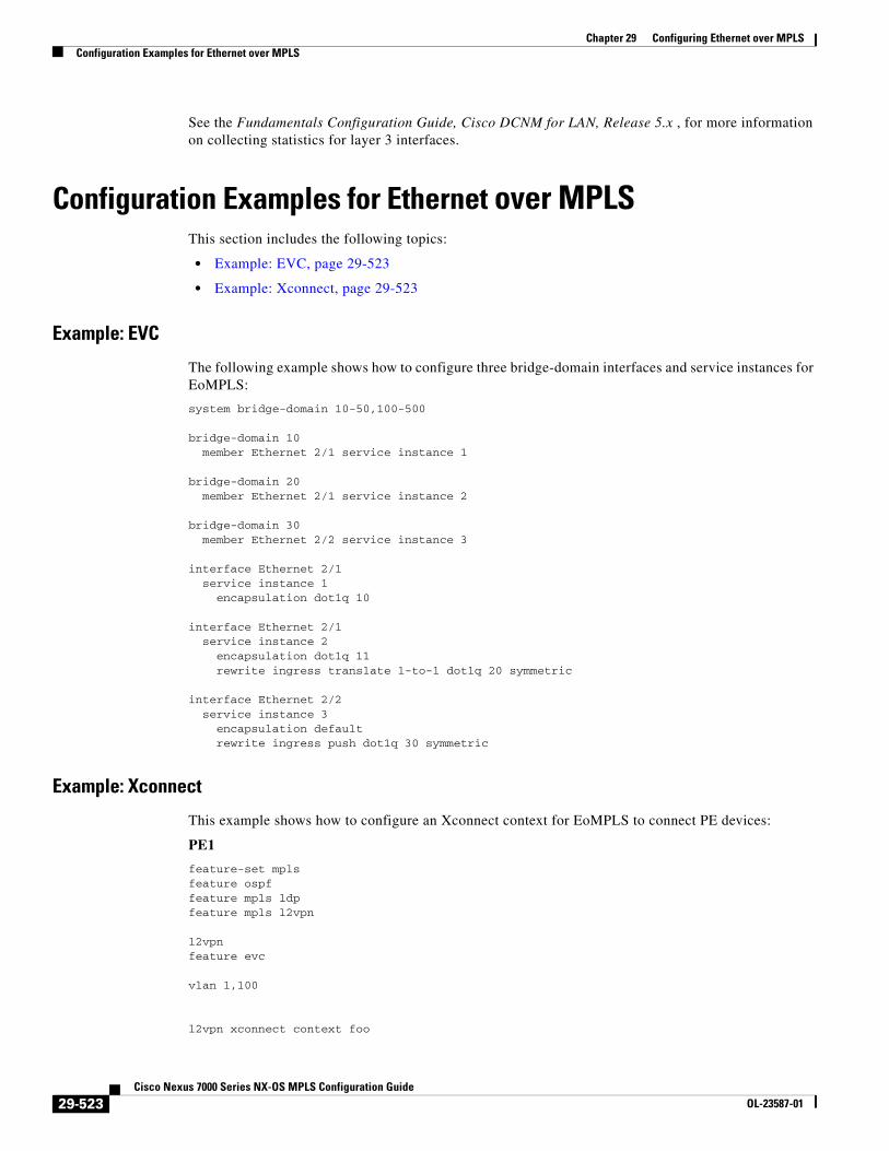
See the Fundamentals Configuration Guide, Cisco DCNM for LAN, Release 5.x , for more information on collecting statistics for layer 3 interfaces.
Configuration Examples for Ethernet over MPLSThis section includes the following topics:
• Example: EVC, page 29-523
• Example: Xconnect, page 29-523
Example: EVC
The following example shows how to configure three bridge-domain interfaces and service instances for EoMPLS:
system bridge-domain 10-50,100-500
bridge-domain 10 member Ethernet 2/1 service instance 1
bridge-domain 20 member Ethernet 2/1 service instance 2
bridge-domain 30 member Ethernet 2/2 service instance 3
interface Ethernet 2/1 service instance 1 encapsulation dot1q 10
interface Ethernet 2/1 service instance 2 encapsulation dot1q 11 rewrite ingress translate 1-to-1 dot1q 20 symmetric
interface Ethernet 2/2 service instance 3 encapsulation default rewrite ingress push dot1q 30 symmetric
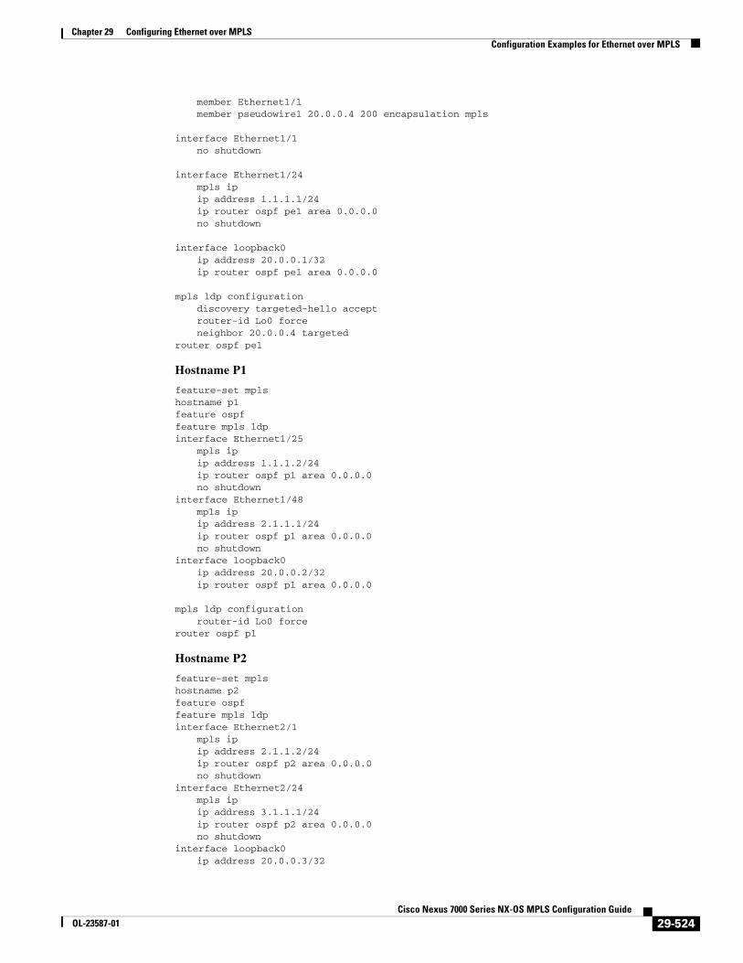
Example: Xconnect
This example shows how to configure an Xconnect context for EoMPLS to connect PE devices:
PE1
feature-set mplsfeature ospffeature mpls ldpfeature mpls l2vpn
l2vpnfeature evc
vlan 1,100
l2vpn xconnect context foo
29-523Cisco Nexus 7000 Series NX-OS MPLS Configuration Guide
OL-23587-01
Chapter 29 Configuring Ethernet over MPLSConfiguration Examples for Ethernet over MPLS
member Ethernet1/1member pseudowire1 20.0.0.4 200 encapsulation mpls
interface Ethernet1/1no shutdown
interface Ethernet1/24mpls ipip address 1.1.1.1/24ip router ospf pe1 area 0.0.0.0no shutdown
interface loopback0ip address 20.0.0.1/32ip router ospf pe1 area 0.0.0.0
mpls ldp configurationdiscovery targeted-hello acceptrouter-id Lo0 forceneighbor 20.0.0.4 targeted
router ospf pe1
Hostname P1
feature-set mplshostname p1feature ospffeature mpls ldpinterface Ethernet1/25
mpls ipip address 1.1.1.2/24ip router ospf p1 area 0.0.0.0no shutdown
interface Ethernet1/48mpls ipip address 2.1.1.1/24ip router ospf p1 area 0.0.0.0no shutdown
interface loopback0ip address 20.0.0.2/32ip router ospf p1 area 0.0.0.0
mpls ldp configurationrouter-id Lo0 force
router ospf p1
Hostname P2
feature-set mplshostname p2feature ospffeature mpls ldpinterface Ethernet2/1
mpls ipip address 2.1.1.2/24ip router ospf p2 area 0.0.0.0no shutdown
interface Ethernet2/24mpls ipip address 3.1.1.1/24ip router ospf p2 area 0.0.0.0no shutdown
interface loopback0ip address 20.0.0.3/32
29-524Cisco Nexus 7000 Series NX-OS MPLS Configuration Guide
OL-23587-01
Chapter 29 Configuring Ethernet over MPLSAdditional References
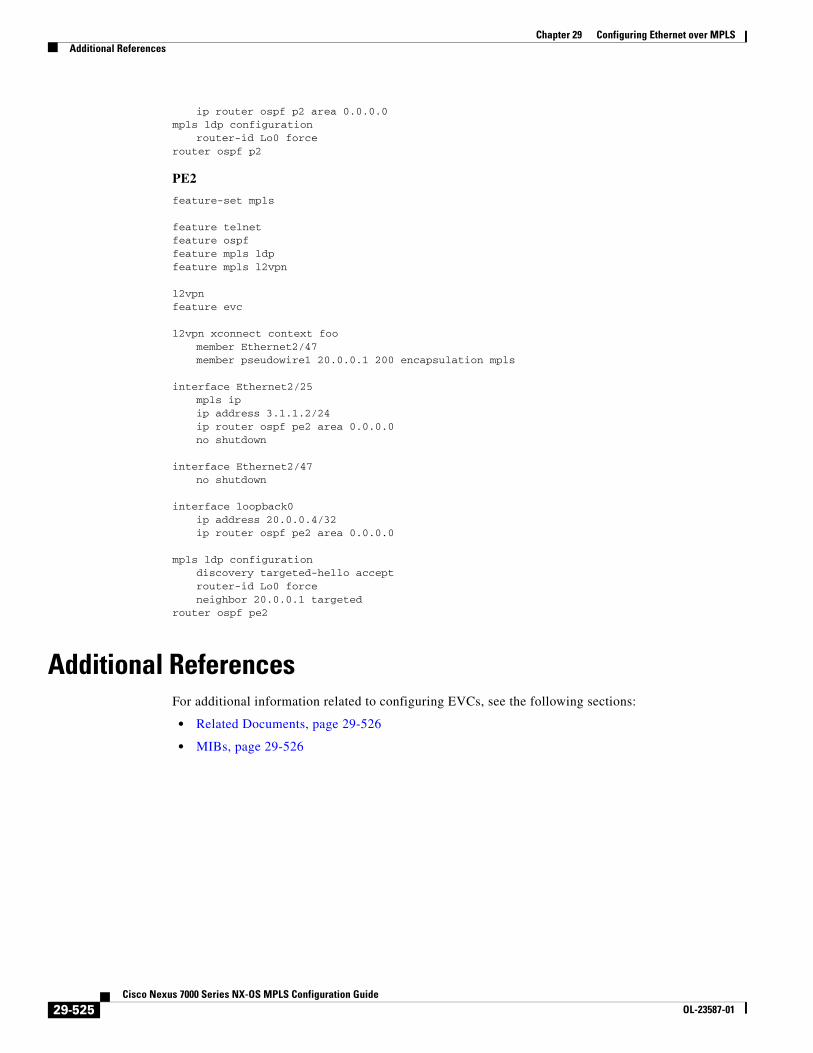
ip router ospf p2 area 0.0.0.0mpls ldp configuration
router-id Lo0 forcerouter ospf p2
PE2
feature-set mpls
feature telnetfeature ospffeature mpls ldpfeature mpls l2vpn
l2vpnfeature evc
l2vpn xconnect context foomember Ethernet2/47member pseudowire1 20.0.0.1 200 encapsulation mpls
interface Ethernet2/25mpls ipip address 3.1.1.2/24ip router ospf pe2 area 0.0.0.0no shutdown
interface Ethernet2/47no shutdown
interface loopback0ip address 20.0.0.4/32ip router ospf pe2 area 0.0.0.0
mpls ldp configurationdiscovery targeted-hello acceptrouter-id Lo0 forceneighbor 20.0.0.1 targeted
router ospf pe2
Additional ReferencesFor additional information related to configuring EVCs, see the following sections:
• Related Documents, page 29-526
• MIBs, page 29-526
29-525Cisco Nexus 7000 Series NX-OS MPLS Configuration Guide
OL-23587-01
Chapter 29 Configuring Ethernet over MPLSFeature History for Ethernet Virtual Circuits
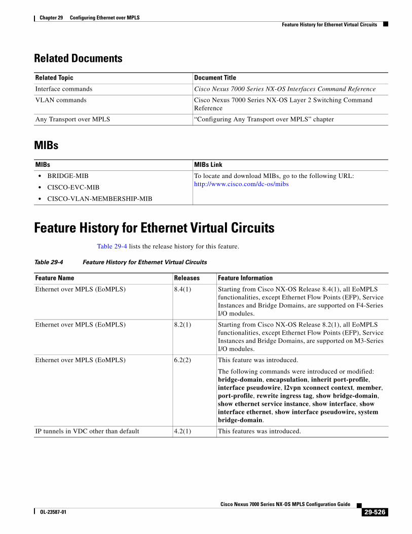
Related Documents
MIBs
Feature History for Ethernet Virtual CircuitsTable 29-4 lists the release history for this feature.
Related Topic Document Title
Interface commands Cisco Nexus 7000 Series NX-OS Interfaces Command Reference
VLAN commands Cisco Nexus 7000 Series NX-OS Layer 2 Switching Command Reference
Any Transport over MPLS “Configuring Any Transport over MPLS” chapter
MIBs MIBs Link
• BRIDGE-MIB
• CISCO-EVC-MIB
• CISCO-VLAN-MEMBERSHIP-MIB
To locate and download MIBs, go to the following URL: http://www.cisco.com/dc-os/mibs
Table 29-4 Feature History for Ethernet Virtual Circuits
Feature Name Releases Feature Information
Ethernet over MPLS (EoMPLS) 8.4(1) Starting from Cisco NX-OS Release 8.4(1), all EoMPLS functionalities, except Ethernet Flow Points (EFP), Service Instances and Bridge Domains, are supported on F4-Series I/O modules.
Ethernet over MPLS (EoMPLS) 8.2(1) Starting from Cisco NX-OS Release 8.2(1), all EoMPLS functionalities, except Ethernet Flow Points (EFP), Service Instances and Bridge Domains, are supported on M3-Series I/O modules.
Ethernet over MPLS (EoMPLS) 6.2(2) This feature was introduced.
The following commands were introduced or modified: bridge-domain, encapsulation, inherit port-profile, interface pseudowire, l2vpn xconnect context, member, port-profile, rewrite ingress tag, show bridge-domain, show ethernet service instance, show interface, show interface ethernet, show interface pseudowire, system bridge-domain.
IP tunnels in VDC other than default 4.2(1) This features was introduced.
29-526Cisco Nexus 7000 Series NX-OS MPLS Configuration Guide
OL-23587-01

Chapter 29 Configuring Ethernet over MPLSFeature History for Ethernet Virtual Circuits
29-527Cisco Nexus 7000 Series NX-OS MPLS Configuration Guide
OL-23587-01
Related Documents