CHAPTER 3-1 Cisco Video Surveillance 4300 and 4500 High-Definition IP Cameras User Guide OL-19609-04 3 Configuring and Managing the IP Camera The Cisco Video Surveillance IP Camera provides configuration windows that you use to configure and manage the IP camera. This chapter explains how to access the configuration windows, describes each window, and provides detailed information about the options that are available in each window. When configuring the IP camera, be aware of these guidelines: • You must install and set up the Cisco Video Surveillance IP camera as described in Chapter 2, “Getting Started,” before you can access the configuration menus. • You must be an IP camera user with administrator privileges to access the configuration windows. • For security, the configuration windows time out after 30 minutes of no activity. If a time out occurs, you are prompted to log back in by entering your user name and password when you next press a key or click an item. When you log back in, the home window appears. This chapter includes these topics: • Accessing Navigating the Configuration Windows, page 3-1 • Feature Setup Windows, page 3-2 • Network Setup Windows, page 3-16 • Administration Windows, page 3-26 • Log Windows, page 3-33 Accessing Navigating the Configuration Windows When you are logged in to the IP camera as a user with administrator privileges, you can access the configuration windows at any time by clicking the Setup link at the top of an IP camera window. (For information about logging in to the IP camera, see the “Accessing the IP Camera” section on page 2-6). When you click Setup, a window appears that includes these components: • Navigation tree—Appears at the left of the window and provides links to each configuration window • Configuration area—Appears to the right of the navigation tree The navigation tree always appears. The right area varies depending on the configuration window that you choose from the navigation tree. Use the Navigation Tree to access each configuration window. To do so, click the link or right arrow next to the link for the group of configuration windows that you want. The name of each associated window appears as a link. Then click the link for the desired window. To collapse a set of links, click the down-arrow next to the top-level link.

Welcome message from author
This document is posted to help you gain knowledge. Please leave a comment to let me know what you think about it! Share it to your friends and learn new things together.
Transcript

Cisco Video Surveillance 43OL-19609-04
C H A P T E R 3
Configuring and Managing the IP CameraThe Cisco Video Surveillance IP Camera provides configuration windows that you use to configure and manage the IP camera. This chapter explains how to access the configuration windows, describes each window, and provides detailed information about the options that are available in each window.
When configuring the IP camera, be aware of these guidelines:
• You must install and set up the Cisco Video Surveillance IP camera as described in Chapter 2, “Getting Started,” before you can access the configuration menus.
• You must be an IP camera user with administrator privileges to access the configuration windows.
• For security, the configuration windows time out after 30 minutes of no activity. If a time out occurs, you are prompted to log back in by entering your user name and password when you next press a key or click an item. When you log back in, the home window appears.
This chapter includes these topics:
• Accessing Navigating the Configuration Windows, page 3-1
• Feature Setup Windows, page 3-2
• Network Setup Windows, page 3-16
• Administration Windows, page 3-26
• Log Windows, page 3-33
Accessing Navigating the Configuration WindowsWhen you are logged in to the IP camera as a user with administrator privileges, you can access the configuration windows at any time by clicking the Setup link at the top of an IP camera window. (For information about logging in to the IP camera, see the “Accessing the IP Camera” section on page 2-6).
When you click Setup, a window appears that includes these components:
• Navigation tree—Appears at the left of the window and provides links to each configuration window
• Configuration area—Appears to the right of the navigation tree
The navigation tree always appears. The right area varies depending on the configuration window that you choose from the navigation tree. Use the Navigation Tree to access each configuration window. To do so, click the link or right arrow next to the link for the group of configuration windows that you want. The name of each associated window appears as a link. Then click the link for the desired window.
To collapse a set of links, click the down-arrow next to the top-level link.
3-100 and 4500 High-Definition IP Cameras User Guide

Chapter 3 Configuring and Managing the IP CameraFeature Setup Windows
The configuration windows are organized as follows:
• Feature Setup
– Streaming
– Camera
– Video Overlay
– IO Ports
– Pan/Tilt
– Event
– Patrol Sequence
– Analytics
• Network Setup
– Basic
– IP Addressing
– Time
– Discovery
– SNMP
– 802.1x
– IP Filtering
– QoS
• Administration
– Initialization
– Users
– Maintenance
– Firmware
– Device Processes
– Password Complexity
• Log
– Setup
– Local Log
Feature Setup WindowsThe Feature Setup windows let you configure a variety of IP camera features and functions. The following sections describe the Feature Setup windows in detail:
• Streaming Settings Window, page 3-3
• Camera Settings Window, page 3-6
• Video Overlay Settings Window, page 3-8
• IO Ports Settings Window, page 3-8
3-2Cisco Video Surveillance 4300 and 4500 High-Definition IP Cameras User Guide
OL-19609-04
Chapter 3 Configuring and Managing the IP CameraFeature Setup Windows
• Pan Tilt Settings Window, page 3-9
• Event Notification Window, page 3-10
• Patrol Sequence Window, page 3-14
• Analytics Windows, page 3-16
Streaming Settings WindowThe Streaming Settings window provides options for configuring audio and video streams from the IP camera. You can configure settings for the primary and an optional secondary video stream.
Configuring a secondary stream is useful for providing a video stream that is at a lower resolution than the primary stream to third-party devices or software.
The primary stream supports H.264 for video and G.711 A-law, G.711 u-law, and AAC for audio. The secondary stream supports MJPEG for video and does not support audio.
When configuring video streams, be aware of the following guidelines:
• You cannot configure a secondary stream (channel 2) if you configure the resolution for the primary stream (channel 1) to 1920 x 1080
• You cannot configure the resolution for the primary stream to 1920 x 1080 if a secondary stream is enabled
• The resolution of the primary stream must be higher than the resolution of the secondary stream
• You cannot configure a maximum frame rate of 60 for the primary stream if the secondary stream is enabled.
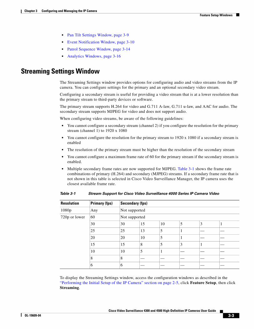
• Multiple secondary frame rates are now supported for MJPEG. Table 3-1 shows the frame rate combinations of primary (H.264) and secondary (MJPEG) streams. If a secondary frame rate that is not shown in this table is selected in Cisco Video Surveillance Manager, the IP camera uses the closest available frame rate.
To display the Streaming Settings window, access the configuration windows as described in the “Performing the Initial Setup of the IP Camera” section on page 2-5, click Feature Setup, then click Streaming.
Table 3-1 Stream Support for Cisco Video Surveillance 4000 Series IP Camera Video
Resolution Primary (fps) Secondary (fps)
1080p Any Not supported
720p or lower 60 Not supported
30 30 15 10 5 3 1
25 25 13 5 1 — —
20 20 10 5 1 — —
15 15 8 5 3 1 —
10 10 5 1 — — —
8 8 — — — — —
6 6 — — — — —
3-3Cisco Video Surveillance 4300 and 4500 High-Definition IP Cameras User Guide
OL-19609-04

Chapter 3 Configuring and Managing the IP CameraFeature Setup Windows
If you change any options in this window, you must click the Save Settings button to save the changes. If you do not click this button, changes are not retained when you exit the window. Save Settings appears at the bottom of the window. You may need to scroll down to it.
Table 3-2 describes the options in the Streaming Settings window.
Table 3-2 Streaming Settings Window Options
Option Description
Current Channel Area
Channel Choose the video stream (Channel 1 or Channel 2) to which the configuration settings in the Streaming Settings window apply. Channel 1 is the primary stream and Channel 2 is the secondary stream.
Enable Channel Check this check box to cause the IP camera to send audio/video data on the selected stream.
Channel Name Name of the video stream.
The name can contain up to 16 characters, which can be letters, numbers, and special characters, but no spaces. Special characters are: ! % ( ) + , - : = @ _ ~
Streaming Setup Area
Note These options apply to the primary stream only.
Enable SRTP Check this check box to enable Secure Real-time Transport Protocol (SRTP), which provides encryption for the audio/video stream from the IP camera.
RTSP Port Transmission Control Protocol (TCP) port on which the IP camera receives Real-Time Streaming Protocol (RTSP) commands. You must configure this port if you want to allow third-party devices or software to access video streams from the IP camera.
RTSP is a standard for connecting a client to control streaming data over the web.
Valid values are 554 and 1024 through 65535. The default port is 554.
Video Source Port Universal Datagram Protocol (UDP) port on which the IP camera transmits Video Real-Time Transport Protocol (RTP) data.
Valid values are even numbers 1024 through 65534. The default port is 1024.
Audio Source Port UDP port on which the IP camera transmits audio RTP data
Valid values even numbers 1024 through 65534. The default value is 1026.
Max RTP Packet Size Maximum number of bytes per data packets that are sent in each RTP request.
Configure a lower number if you are streaming video to a cell phone that requires smaller data packets.
Valid values are 400 through 1400. The default value is 1400.
Enable Multicast Check this check box to send video and audio data as a multicast stream.
When multicast is enabled, the IP camera sends video and audio to the multicast addresses that you designate. Multicast enables several devices to receive the video signal from the IP camera simultaneously.
Multicast Address Enter the multicast IP address on which the IP camera sends a multicast audio/video stream.
3-4Cisco Video Surveillance 4300 and 4500 High-Definition IP Cameras User Guide
OL-19609-04

Chapter 3 Configuring and Managing the IP CameraFeature Setup Windows
Multicast Video Port Enter the port on which the IP camera sends a multicast video stream.
Valid values are even numbers 1024 through 65532.
Multicast Audio Port Enter the port on which the IP camera sends a multicast audio stream.
Valid values are even numbers 1024 through 65532.
Time to Live Enter the number of hops, which specifies the number of network devices that an audio/video stream can pass before arriving at its destination or being dropped.
Valid values are 1 through 255.
Video Area
Video Standard Choose the system for video transmission: NTSC or PAL.
The setting that you make affects each channel that is enabled.
Video Codec Display only: Shows the codec for video transmission: H.264 for the primary stream and MJPEG for the secondary stream.
Video Resolution Choose the resolution for video transmission. The resolutions in this drop-down list depend on the video standard that you selected.
You can also change the resolution for video transmission by using the Video Resolution drop-down list in the Camera Video/Control window, as described in Table 4-1.
Maximum Frame Rate Choose the maximum frame rate of the video stream.
Video Quality Choose an option for the video quality of the primary video stream from the IP camera:
• Constant Bit Rate—Available for the primary stream only. Specifies that the video stream is output at or close to the constant bit rate that you choose. The default value is 4 Mbps. A higher bit rate provides better video quality but consumes more bandwidth.
• Fixed Quality—Specifies that video is output at a fixed quality, which ranges from Very High to Low. The bit rate may vary to maintain this quality. The default fixed quality is Normal. A higher fixed quality provides better video quality but consumes more bandwidth.
You can use these options to help manage bandwidth use in your network. For example, if the IP camera is focused on an area with little movement, such as an emergency exit, you can configure it with a low fixed quality.
Audio Setup Area
Note These options apply to the primary stream only.
Enable Audio Check this check box if you if you want the IP camera to transmit and receive audio.
Audio Compression Choose the codec (G.711 A-Law, G.711 u-Law, or AAC) for audio that is transmitted from the IP camera.
AAC provides highest quality audio and consumes the least bandwidth.
The default value is G.711 A-law.
Table 3-2 Streaming Settings Window Options (continued)
Option Description
3-5Cisco Video Surveillance 4300 and 4500 High-Definition IP Cameras User Guide
OL-19609-04
Chapter 3 Configuring and Managing the IP CameraFeature Setup Windows
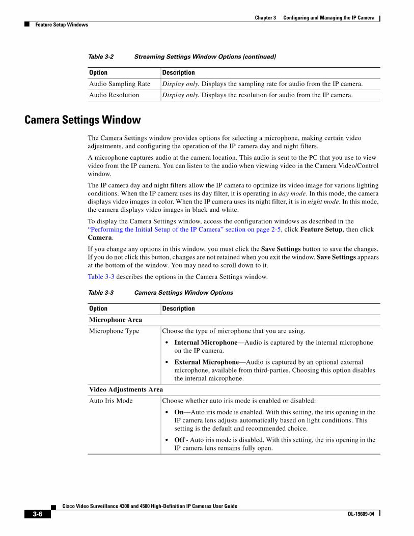
Camera Settings WindowThe Camera Settings window provides options for selecting a microphone, making certain video adjustments, and configuring the operation of the IP camera day and night filters.
A microphone captures audio at the camera location. This audio is sent to the PC that you use to view video from the IP camera. You can listen to the audio when viewing video in the Camera Video/Control window.
The IP camera day and night filters allow the IP camera to optimize its video image for various lighting conditions. When the IP camera uses its day filter, it is operating in day mode. In this mode, the camera displays video images in color. When the IP camera uses its night filter, it is in night mode. In this mode, the camera displays video images in black and white.
To display the Camera Settings window, access the configuration windows as described in the “Performing the Initial Setup of the IP Camera” section on page 2-5, click Feature Setup, then click Camera.
If you change any options in this window, you must click the Save Settings button to save the changes. If you do not click this button, changes are not retained when you exit the window. Save Settings appears at the bottom of the window. You may need to scroll down to it.
Table 3-3 describes the options in the Camera Settings window.
Audio Sampling Rate Display only. Displays the sampling rate for audio from the IP camera.
Audio Resolution Display only. Displays the resolution for audio from the IP camera.
Table 3-2 Streaming Settings Window Options (continued)
Option Description
Table 3-3 Camera Settings Window Options
Option Description
Microphone Area
Microphone Type Choose the type of microphone that you are using.
• Internal Microphone—Audio is captured by the internal microphone on the IP camera.
• External Microphone—Audio is captured by an optional external microphone, available from third-parties. Choosing this option disables the internal microphone.
Video Adjustments Area
Auto Iris Mode Choose whether auto iris mode is enabled or disabled:
• On—Auto iris mode is enabled. With this setting, the iris opening in the IP camera lens adjusts automatically based on light conditions. This setting is the default and recommended choice.
• Off - Auto iris mode is disabled. With this setting, the iris opening in the IP camera lens remains fully open.
3-6Cisco Video Surveillance 4300 and 4500 High-Definition IP Cameras User Guide
OL-19609-04

Chapter 3 Configuring and Managing the IP CameraFeature Setup Windows
Sensitivity Designates how the iris opening in the IP camera lens adjusts when auto iris mode is enabled. As sensitivity increases, the auto iris closes more to reduce the light level and increase the depth of field in bright environments. However, a high sensitivity may cause the image to oscillate between bright and dim. In this situation, reduce the sensitivity to improve the image quality.
White Balance Mode Choose one the following white balance modes from the drop-down list:
• Manual—Choose this option if you want to set the white balance by using the White Balance slider in the Camera Video/Control window as described in Chapter 4, “Viewing Live Video.”
• Auto—Suitable for most conditions that do not have special lighting
• Indoor (incandescent)—Suitable for indoor conditions
• Fluorescent (white light)—Suitable for indoor conditions with fluorescent white lighting
• Fluorescent (yellow light)—Suitable for indoor conditions with fluorescent yellow lighting
• Outdoor—Suitable for outdoor conditions.
The default setting is Auto.
Day Night Filter Area
Filter Type Choose the day/night mode for the IP camera:
• Day—IP camera always remains in day mode.
• Night—IP camera always remains in night mode.
• Auto—IP camera automatically switches between day and night mode based on the lighting condition threshold that you specify.
Day to Night Threshold If the Filter Type day/night mode is set to Auto, choose the value that specifies the relative light threshold at which the IP camera switches from day to night mode. A lower value designates that the IP camera switches from day to night mode in brighter conditions. A higher value designated that the IP camera switches modes in darker conditions.
The default value is 10.
Night to Day Threshold If the Filter Type day/night mode is set to Auto, choose the value that specifies the relative light threshold at which the IP camera switches from night to day mode. A lower value designates that the IP camera switches from night to day mode in darker conditions. A higher value designated that the IP camera switches modes in lighter conditions.
The default value is 15.
Enable Night Vision Schedule
Check this check box if you want to configure the times that the camera switches to and from night mode. Enabling the Night Vision Schedule disables the Filter Type option.
Note If you configure a schedule, make sure that the time on the IP camera is set correctly.
Start Time Enter the time, in 24 hour format, that the camera enables its night filter.
End Time Enter the time, in 24 hour format, that the camera disables its night filter.
Table 3-3 Camera Settings Window Options (continued)
Option Description
3-7Cisco Video Surveillance 4300 and 4500 High-Definition IP Cameras User Guide
OL-19609-04

Chapter 3 Configuring and Managing the IP CameraFeature Setup Windows
Video Overlay Settings WindowThe Video Overlay Settings window provides options for configuring overlay information that appears on the video image in the Camera Video/Control window.
To display the Video Overlay Settings window, access the configuration windows as described in the “Performing the Initial Setup of the IP Camera” section on page 2-5, click Feature Setup, then click Video Overlay.
If you change any options in this window, you must click the Save Settings button to save the change. If you do not click this button, changes are not retained when you exit the window. Save Settings appears at the bottom of the window. You may need to scroll down to it.
Table 3-4 describes the option in the Video Overlay Settings window.
IO Ports Settings WindowThe IO Ports Settings window lets you configure various options for the two input and two output ports on the IP camera. A state change of an input ports triggers a camera to take configured actions. Output ports send signals that can control external devices, such as alarms or door switches.
The IP camera can trigger an action only when the input that is received on an input port comes from a contact that is in a normally closed condition. The camera triggers the action when the contact changes to an open condition.
To display the IO Ports Settings window, access the configuration windows as described in the “Performing the Initial Setup of the IP Camera” section on page 2-5, click Feature Setup, then click IO Ports.
If you change the option in this window, you must click the Save Settings button to save the change. If you do not click this button, changes are not retained when you exit the window. Save Settings appears at the bottom of the window. You may need to scroll down to it.
Table 3-5 describes the option in the IO Ports Settings window.
Table 3-4 Video Overlay Settings Window Options
Option Description
Text Overlay Area
Enable Time Stamp Check this check box to display the time from the internal clock of the IP camera as an overlay on the video image from the IP camera.
Enable Text Display Check this check box to display the text that you enter in the Display Text field as an overlay on the video image from the IP camera.
This option can be useful for identifying this IP camera in an installation with several IP cameras.
Display Text If you check the Enable Text Display check box, the text that you enter in this field appears as an overlay on the video image from the IP camera.
The text can contain up to 26 characters, which can include letters, numbers, spaces, and these characters: ! $ % ( ) + , - . / : = @ ^ _ ` { } ~
3-8Cisco Video Surveillance 4300 and 4500 High-Definition IP Cameras User Guide
OL-19609-04

Chapter 3 Configuring and Managing the IP CameraFeature Setup Windows
Pan Tilt Settings WindowThe Pan Tilt Settings window provides options for configuring pan and tilt functions for the IP camera. These functions require that the IP camera be installed with a pan/tilt mount that supports the Pelco D protocol.
If you use a pan/tilt mount that requires RS-422 or RS-485 connections, you must connect the mount to the IP camera through a Cisco data converter (part number CIVS-KYBD22232-B).
To display the Pan Tilt Settings window, access the configuration windows as described in the “Performing the Initial Setup of the IP Camera” section on page 2-5, click Feature Setup, then click Pan/Tilt.
If you change any options in this window, you must click the Save Settings button to save the change. If you do not click this button, changes are not retained when you exit the window. Save Settings appears at the bottom of the window. You may need to scroll down to it.
Table 3-6 describes the option in the Pan Tilt Settings window.
Table 3-5 IO Ports Settings Window Options
Option Description
Input Ports Area
Port # Display only. Indicates input port 1 and input port 2.
Current State Display only. Indicates the current state (high or low) of the corresponding port.
Event Trigger Choose the state (Rising or Falling) that triggers designated camera actions. When an input port changes to the configured state, the camera determines that an event has occurred and takes the actions that you have configured.
Output Ports
Port # Display only. Indicates output port 1 and output port 2.
Current State Display only. Indicates the current state (high or low) of the corresponding port.
Default State Choose the state (low or high) that the corresponding port is set to when the IP camera powers on or resets.
The port changes to this state when you click Save Settings.
The default setting is High.
Event Action Display only. Indicates the current state (high or low) that the output port changes to when an event occurs.
Automatic Reset Check this check box if you want the corresponding output port to go back to its default state after an event occurs.
Duration If you checked the Automatic Reset check box, enter the amount of time, in milliseconds, that elapses before the port goes back to its default state after an event changes it from the default state.
3-9Cisco Video Surveillance 4300 and 4500 High-Definition IP Cameras User Guide
OL-19609-04

Chapter 3 Configuring and Managing the IP CameraFeature Setup Windows
Event Notification WindowThe Event Notification window provides options for how the IP camera handles events. An event is any of the following:
• A change of state from low to high or from high to low on an input port of the IP camera. For related information about input ports, see the “IO Ports Settings Window” section on page 3-8.
• Motion that the IP camera detects. For related information about motion detection, see the “Motion detection controls” rows in Table 4-1.
• Loss of video signal.
When an event occurs, it triggers the IP camera to take certain configured actions:
• HTTP notification—IP camera sends notification to a remote system via HTTP. This information includes the following:
– Device ID—ID of the IP camera
– Device name—Name of the IP camera
– IP address—IP address of the IP camera
– MAC address—MAC address of the IP camera
– Channel ID—Channel identification number (1 for primary stream or 2 for secondary stream)
– Channel name—Name that is configured for the channel
– Date and time—Date and time that the event occurred
– Active post Count—Sequence number of the notification for this event
– Event type—Type of event
Table 3-6 Pan Tilt Settings Window Options
Option Description
Pan/Tilt Area
Pan and Tilt Enabled Check this check box to enable pan and tilt operation for the IP camera.
Protocol Display only. Indicates the protocol for the pan/tilt functionality.
Address Enter the logical address of the external PTZ device.
To determine this address, refer to the documentation for that device.
RS-232 Settings
Baud Rate Choose the Baud rate value that is configured on the device that controls the pan and tilt functions of the IP camera.
The default setting is 4800 bps.
Data Bits Display only. Indicates the data bits configuration for the serial port on the IP camera.
Parity Display only. Indicates the parity configuration for the serial port on the IP camera.
Stop Bits Display only. Indicates the stop bits configuration for the serial port on the IP camera.
3-10Cisco Video Surveillance 4300 and 4500 High-Definition IP Cameras User Guide
OL-19609-04
Chapter 3 Configuring and Managing the IP CameraFeature Setup Windows
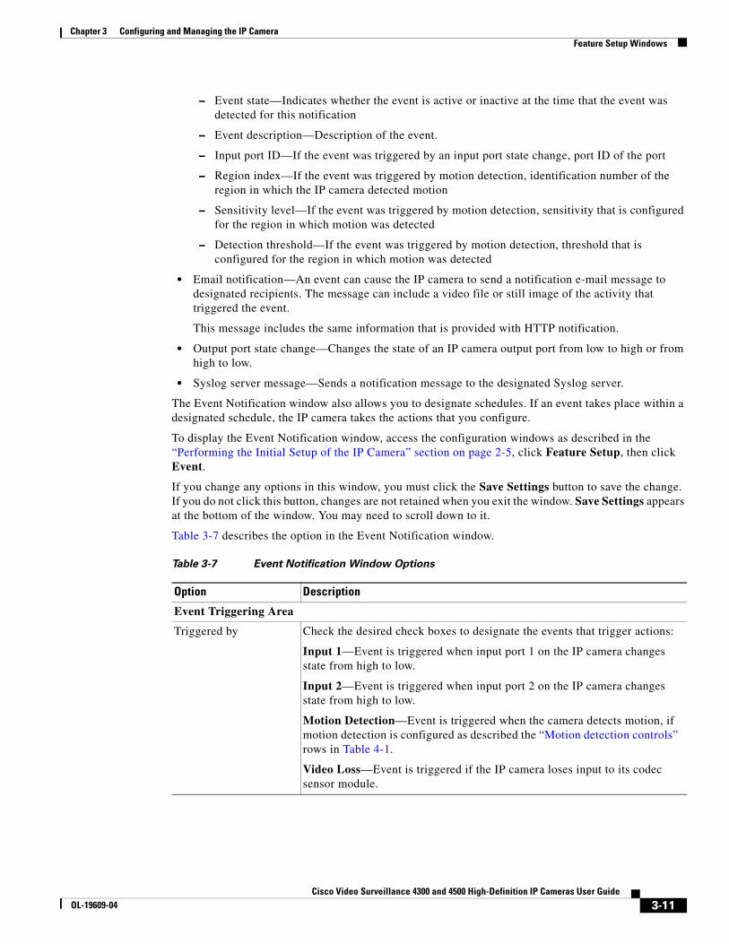
– Event state—Indicates whether the event is active or inactive at the time that the event was detected for this notification
– Event description—Description of the event.
– Input port ID—If the event was triggered by an input port state change, port ID of the port
– Region index—If the event was triggered by motion detection, identification number of the region in which the IP camera detected motion
– Sensitivity level—If the event was triggered by motion detection, sensitivity that is configured for the region in which motion was detected
– Detection threshold—If the event was triggered by motion detection, threshold that is configured for the region in which motion was detected
• Email notification—An event can cause the IP camera to send a notification e-mail message to designated recipients. The message can include a video file or still image of the activity that triggered the event.
This message includes the same information that is provided with HTTP notification.
• Output port state change—Changes the state of an IP camera output port from low to high or from high to low.
• Syslog server message—Sends a notification message to the designated Syslog server.
The Event Notification window also allows you to designate schedules. If an event takes place within a designated schedule, the IP camera takes the actions that you configure.
To display the Event Notification window, access the configuration windows as described in the “Performing the Initial Setup of the IP Camera” section on page 2-5, click Feature Setup, then click Event.
If you change any options in this window, you must click the Save Settings button to save the change. If you do not click this button, changes are not retained when you exit the window. Save Settings appears at the bottom of the window. You may need to scroll down to it.
Table 3-7 describes the option in the Event Notification window.
Table 3-7 Event Notification Window Options
Option Description
Event Triggering Area
Triggered by Check the desired check boxes to designate the events that trigger actions:
Input 1—Event is triggered when input port 1 on the IP camera changes state from high to low.
Input 2—Event is triggered when input port 2 on the IP camera changes state from high to low.
Motion Detection—Event is triggered when the camera detects motion, if motion detection is configured as described the “Motion detection controls” rows in Table 4-1.
Video Loss—Event is triggered if the IP camera loses input to its codec sensor module.
3-11Cisco Video Surveillance 4300 and 4500 High-Definition IP Cameras User Guide
OL-19609-04

Chapter 3 Configuring and Managing the IP CameraFeature Setup Windows
Actions Check the desired check boxes to designate that actions that the IP camera takes when the corresponding trigger occurs.
• Email—Sends information about the event in an e-mail message to the designated recipient. You design the recipient and configure other e-mail options in other fields in this window.
• Output 1—Changes the state of the output 1 port on the IP camera as defined in the Port Settings window.
• Output 2—Changes the state of the output 2 port on the IP camera as defined in the Port Settings window.
• Syslog—Sends information about the event to a designated Syslog server.
• HTTP—Sends information about the event as an HTTP stream to a remote system.
Event Scheduling Area
Scheduling Grid Designate the times at which an event causes the IP camera to take the designed actions. If an event occurs during a time that is not designated, the IP camera does not take any action.
Each cell in this grid represents one hour on the corresponding day, starting at 12:00 a.m. (0:00). To designate times, click the desired cells. Selected cells appear shaded.
To select all times, click the Set All button.
To deselect all times, click the Clear All button.
To change the scheduling settings to the last saved configuration, click Undo.
Set All button Selects all cells in the scheduling grid.
Clear All button Deselects all cells in the scheduling grid.
Undo All button Deselects cells in the scheduling grid that you selected since last saving Event Notification window settings.
HTTP Notification Area
Primary HTTP Server Identify the primary server to which HTTP messages are sent by choosing IP Address or Hostname from the drop-down list and entering the IP address or host name in the corresponding field.
URL Base Enter a string to be used as the prefix in the HTTP URL. The HTTP URL is sent in this format:
http://<IP address>/<URL Base>?<system-provided-name-value-pairs>
where IP address is the IP address of the destination server, URL Base is the string that you enter, and system-provided-name-value-pairs is information about the event.
Port Number Enter the port number that receives messages on the primary server to which HTTP messages are sent.
Table 3-7 Event Notification Window Options (continued)
Option Description
3-12Cisco Video Surveillance 4300 and 4500 High-Definition IP Cameras User Guide
OL-19609-04

Chapter 3 Configuring and Managing the IP CameraFeature Setup Windows
User Name If authentication is required on the primary server to which HTTP messages are sent, enter the user name.
Password If authentication is required on the primary server to which HTTP messages are sent, enter the password.
HTTP Authentication If authentication is required on the primary server to which HTTP messages are sent, choose the authentication method.
Secondary HTTP Server Identify an optional secondary server to which HTTP messages are sent by choosing IP Address or Hostname from the drop-down list and entering the IP address or host name in the corresponding field.
URL Base Enter a string to be used as the prefix in the HTTP URL for the secondary server. The HTTP URL is sent in this format:
http://<IP address>/<URL Base>?<system-provided-name-value-pairs>
where IP address is the IP address of the destination server, URL Base is the string that you enter, and system-provided-name-value-pairs is information about the event.
Port Number Enter the port number that receives messages on the secondary server to which HTTP messages are sent.
User Name If authentication is required on the secondary server to which HTTP messages are sent, enter the user name.
Password If authentication is required on the secondary server to which HTTP messages are sent, enter the password.
HTTP Authentication If authentication is required on the secondary server to which HTTP messages are sent, choose the authentication method.
Email Notification Area
Primary SMTP Server Identify the primary SMTP server that is used for sending e-mail by choosing IP Address or Hostname from the drop-down list and entering the IP address or host name in the corresponding field.
Primary SMTP Port Enter the port number for the primary SMTP server.
POP Server Identify the primary POP server that is used for sending e-mail by choosing IP Address or Hostname from the drop-down list and entering the IP address or host name in the corresponding field.
This field is dimmed if you do not choose Requires POP Before SMTP in the Authentication field that follows.
Authentication If the primary SMTP server requires authentication to send e-mail, choose the appropriate authentication type. The authentication type typically is the same as that for the POP3 server that you use to receive e-mail.
Account Name If the primary SMTP server requires authentication, enter the account name for the server.
Password If the primary SMTP server requires authentication, enter the account password for the server.
Table 3-7 Event Notification Window Options (continued)
Option Description
3-13Cisco Video Surveillance 4300 and 4500 High-Definition IP Cameras User Guide
OL-19609-04

Chapter 3 Configuring and Managing the IP CameraFeature Setup Windows
Patrol Sequence WindowThe Preset Settings window provides options for configuring a patrol sequence for the IP camera. A patrol sequence consists of up to eight steps, each of which causes the camera to move to a designated preset position and remain in the position for a designated time.
When you create a patrol sequence, you define the order of the steps. When the patrol sequence executes, the IP camera goes to the preset position that is defined by the first step, then moves through each preset position in the configured order. It stops at the preset position that is defined by the last step.
Before you can configure a patrol sequence, you must define preset positions as described in the “Presets controls” rows in Table 4-1. These rows also explain how to start and stop the execution of a patrol sequence.
Secondary SMTP Server
Identify an optional secondary SMTP server that is used for sending e-mail by choosing IP Address or Hostname from the drop-down list and entering the IP address or host name in the corresponding field.
Secondary SMTP Port Enter the port number for the secondary SMTP server.
POP Server Identify an optional secondary POP server that is used for sending e-mail by choosing IP Address or Hostname from the drop-down list and entering the IP address or host name in the corresponding field.
This field is dimmed if you do not choose Requires POP Before SMTP in the Authentication field that follows.
Authentication If the secondary SMTP server requires authentication to send e-mail, choose the appropriate authentication type. The authentication type typically is the same as that for the POP3 server that you use to receive e-mail.
Account Name If the secondary SMTP server requires authentication, enter the account name for the server.
Password If the secondary SMTP server requires authentication, enter the account password for the server.
Send To Enter an e-mail address to which an e-mail message is sent when an event occurs.
Show From Address As Enter the e-mail address to be shown in the From field for the e-mail message that is sent when an event occurs.
Subject Enter the text to be shown in the Subject field for the e-mail messages that the IP camera sends when events occur. The subject can contain up to 118 characters, including spaces.
Attach Video Streaming URL Address
Check this check box to include in the e-mail message body the URL from which the recipient can access the live video stream from the camera on which the event was detected.
Attach Snapshot Check this check box to include with the e-mail message a still picture from the beginning of the event. This snapshot is stored on the IP camera until the message is sent.
This functionality is available only when the secondary video stream is enabled.
Table 3-7 Event Notification Window Options (continued)
Option Description
3-14Cisco Video Surveillance 4300 and 4500 High-Definition IP Cameras User Guide
OL-19609-04

Chapter 3 Configuring and Managing the IP CameraFeature Setup Windows
To display the Patrol Sequence window, access the configuration windows as described in the “Performing the Initial Setup of the IP Camera” section on page 2-5, click Feature Setup, then click Patrol Sequence.
If you change any options in this window, you must click the Save Settings button to save the change. If you do not click this button, changes are not retained when you exit the window. Save Settings appears at the bottom of the window. You may need to scroll down to it.
Table 3-8 describes the option in the Patrol Sequence window.
Table 3-8 Patrol Sequence Window Options
Option Description
Patrol Sequence Area
Dwell Time Choose the length of time in seconds that the camera remains in each preset position when a patrol sequence executes.
Available list
Selected list
Configure the order in which the IP camera executes up to 8 steps in a patrol sequence. The Available list displays preset positions that you can use in the patrol sequence. You define these preset positions in the Camera Video/Control window. The Selected list displays the steps in the patrol sequence.
When the patrol sequence executes, the IP camera goes to the first preset position in the Selected list, then moves through each position in the list in order. It remains in each position for the time that is defined in the Time Delay field. It stops at the last position in the list.
To move preset positions between the Available list and the Selected list, use the following buttons. Buttons become highlighted when they are available.
—Move the selected preset position or positions from the Available list to the Selected list. To select a preset position, click it to highlight it. To select more than one preset positions, Ctrl-click each one.
—Move the selected preset position or positions from the Selected list to the Available list. To select a preset position, click it to highlight it. To select more than one preset positions, Ctrl-click each one.
—Move all preset positions from the Available list to the Selected list.
—Move all preset positions from the Selected list to the Available list.
To configure the order of steps in the Selected list, use the following buttons. Buttons become highlighted when they are available. To select a preset position, click it to highlight it.
—Move the selected preset position to the top of the list.
—Move the selected preset position up one position.
—Move the selected preset position down one position.
—Move the selected preset position to the bottom of the list.
3-15Cisco Video Surveillance 4300 and 4500 High-Definition IP Cameras User Guide
OL-19609-04

Chapter 3 Configuring and Managing the IP CameraNetwork Setup Windows
Analytics WindowsThe Analytics windows provide access to options for configuring the Cisco video analytics feature.
To display the Analytics windows, access the configuration windows as described in the “Performing the Initial Setup of the IP Camera” section on page 2-5, click Feature Setup, then click Analytics. A new browser session starts and the Analytics Home window appears. This window displays video from the IP camera and provides access to other windows that contain information and configuration options.
For detailed information about Cisco video analytics and the Analytics windows, see Cisco Video Analytics User Guide.
Note The Cisco video analytics feature requires Cisco Video Surveillance Manager (VSM) 6.3.1 or later to process analytics events. For related information, see the current version of Cisco Video Surveillance Manager User Guide.
Network Setup WindowsThe Network Setup windows let you configure various network-related settings for the IP camera.
The following sections describe the Network Setup windows in detail:
• Basic Settings Window, page 3-16
• IP Addressing Window, page 3-17
• Time Settings Window, page 3-18
• Discovery Settings Window, page 3-20
• SNMP Settings Window, page 3-21
• 802.1x Settings Window, page 3-23
• IP Filter Settings Window, page 3-24
• QoS Settings Window, page 3-25
Basic Settings WindowThe Basic Settings window provides options for identifying the IP camera and controlling basic operations.
To display the Basic Settings window, access the configuration windows as described in the “Performing the Initial Setup of the IP Camera” section on page 2-5, click Network Setup, then click Basic.
If you change any options in this window, you must click the Save Settings button to save the changes. If you do not click this button, changes are not retained when you exit the window. Save Settings appears at the bottom of the window. You may need to scroll down to it.
Table 3-9 describes the options in the Basic Settings window.
3-16Cisco Video Surveillance 4300 and 4500 High-Definition IP Cameras User Guide
OL-19609-04

Chapter 3 Configuring and Managing the IP CameraNetwork Setup Windows
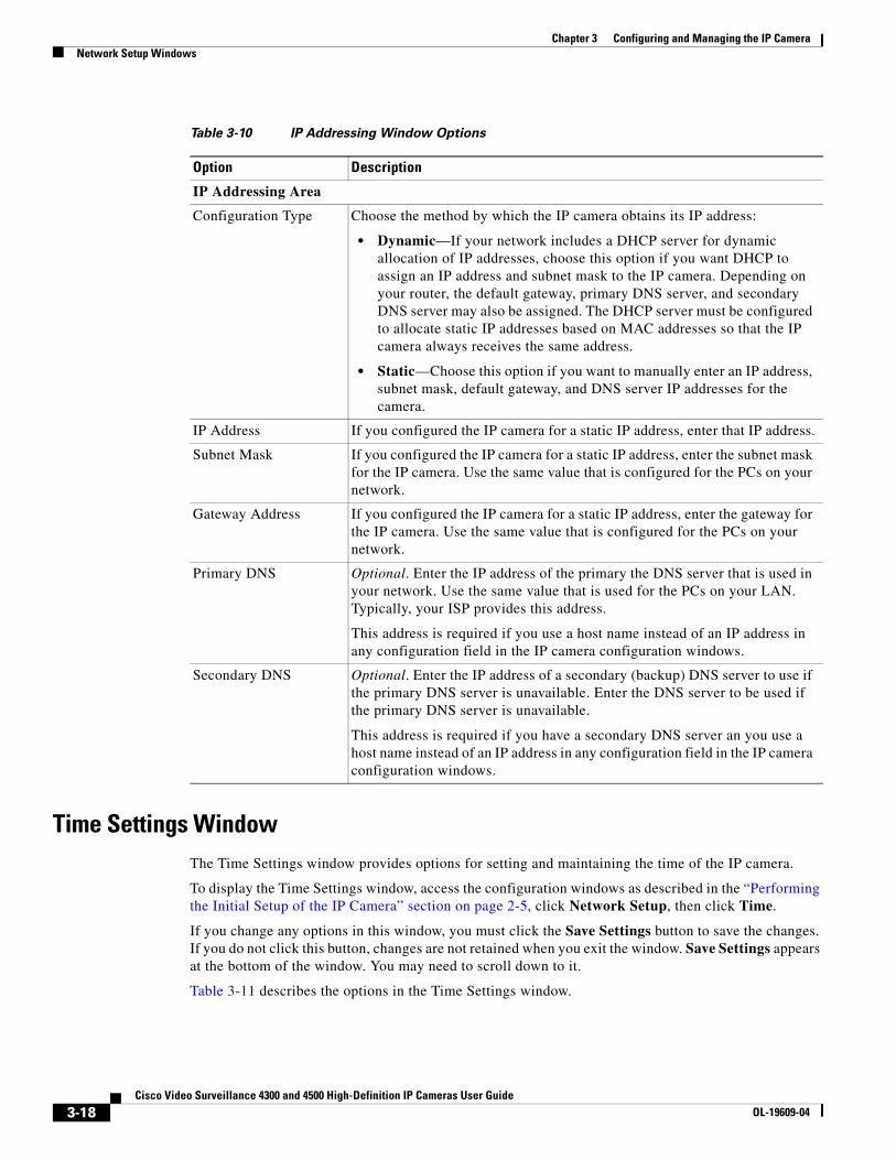
IP Addressing WindowThe IP Addressing window provides options for configuring the IP address of the IP camera.
To display the IP Addressing window, access the configuration windows as described in the “Performing the Initial Setup of the IP Camera” section on page 2-5, click Network Setup, then click IP Addressing.
If you change any options in this window, you must click the Save Settings button to save the changes. If you do not click this button, changes are not retained when you exit the window. Save Settings appears at the bottom of the window. You may need to scroll down to it.
Table 3-10 describes the options in the IP Addressing window.
Table 3-9 Basic Settings Window Options
Option Description
Basic Settings Area
ID Enter a unique identification for the IP camera, which is used to identify the IP camera to various external applications.
The ID can contain up to 64 numbers.
Name Enter a name for the IP camera. This name appears in the IP camera log file for information that is associated with this IP camera.
The name can contain up to 64 characters, which can include letters, numbers, spaces, and these characters: ! $ % ( ) + , - . / = @ ^ _ ` { } ~. Cisco recommends that you give each IP camera a unique name so that you can identify it easily.
Description Enter a description of the IP camera. For example, enter the IP camera location, such as “North Entrance Camera 1.”
The description can contain up to 128 characters, which can include letters, numbers, spaces, and these characters: ! $ % ( ) + , - . / = @ ^ _ ` { } ~
Location Enter the physical location of the IP camera, such as “North Entrance.”
The location can contain up to 64 characters, which can include letters, numbers, spaces, and these characters: ! $ % ( ) + , - . / = @ ^ _ ` { } ~
Contact Enter system contact information for someone such as the system administrator. For example, enter the e-mail address of the system administrator.
The contact can contain up to 64 characters, which can include letters, numbers, spaces, and these characters: ! $ % ( ) + , - . / = @ ^ _ ` { } ~
Basic Device Operations Area
Enable Power LED Check this check box if you want the Power LED on the back of the IP camera to light.
If you do not check this check box, this LED does not light.
3-17Cisco Video Surveillance 4300 and 4500 High-Definition IP Cameras User Guide
OL-19609-04
Chapter 3 Configuring and Managing the IP CameraNetwork Setup Windows
Time Settings WindowThe Time Settings window provides options for setting and maintaining the time of the IP camera.
To display the Time Settings window, access the configuration windows as described in the “Performing the Initial Setup of the IP Camera” section on page 2-5, click Network Setup, then click Time.
If you change any options in this window, you must click the Save Settings button to save the changes. If you do not click this button, changes are not retained when you exit the window. Save Settings appears at the bottom of the window. You may need to scroll down to it.
Table 3-11 describes the options in the Time Settings window.
Table 3-10 IP Addressing Window Options
Option Description
IP Addressing Area
Configuration Type Choose the method by which the IP camera obtains its IP address:
• Dynamic—If your network includes a DHCP server for dynamic allocation of IP addresses, choose this option if you want DHCP to assign an IP address and subnet mask to the IP camera. Depending on your router, the default gateway, primary DNS server, and secondary DNS server may also be assigned. The DHCP server must be configured to allocate static IP addresses based on MAC addresses so that the IP camera always receives the same address.
• Static—Choose this option if you want to manually enter an IP address, subnet mask, default gateway, and DNS server IP addresses for the camera.
IP Address If you configured the IP camera for a static IP address, enter that IP address.
Subnet Mask If you configured the IP camera for a static IP address, enter the subnet mask for the IP camera. Use the same value that is configured for the PCs on your network.
Gateway Address If you configured the IP camera for a static IP address, enter the gateway for the IP camera. Use the same value that is configured for the PCs on your network.
Primary DNS Optional. Enter the IP address of the primary the DNS server that is used in your network. Use the same value that is used for the PCs on your LAN. Typically, your ISP provides this address.
This address is required if you use a host name instead of an IP address in any configuration field in the IP camera configuration windows.
Secondary DNS Optional. Enter the IP address of a secondary (backup) DNS server to use if the primary DNS server is unavailable. Enter the DNS server to be used if the primary DNS server is unavailable.
This address is required if you have a secondary DNS server an you use a host name instead of an IP address in any configuration field in the IP camera configuration windows.
3-18Cisco Video Surveillance 4300 and 4500 High-Definition IP Cameras User Guide
OL-19609-04

Chapter 3 Configuring and Managing the IP CameraNetwork Setup Windows
Table 3-11 Time Settings Window Options
Option Description
Set Time Mode Area
Manually Configure Time
Choose this option if you want to set the time for the IP camera manually.
Use NTP Server to Update Time
Choose this option if you want the IP camera to obtain its time from a network time protocol (NTP) server.
If you check this check box, the camera contacts the designated NTP server every 64 seconds and synchronizes its internal clock with the time of that server.
Local Time Area
Note These options do not apply if you choose the Use NTP Server to Update Time option.
Set Local Date Enter a date for the IP camera. The camera is updated with this date when you click Save Settings.
Set Local Time Enter a time for the IP camera. The camera is updated with this time when you click Save Settings.
Clone PC Time button Click this button to update the IP camera date and time with the date and time of the PC that you are using.
Time Zone and Daylight Saving Area
Time Zone Choose the time zone in which the IP camera is located.
The time that appears when you view video from this IP camera reflects this time zone.
Adjust for Daylight Saving Time
Check this check box if you want the time of the IP camera to adjust automatically for daylight saving time.
Edit Default Daylight Saving Configuration for Time Zone
Check this check box if you want the daylight saving time adjustment of the IP camera to be different than the default adjustment for the selected time zone.
Time Offset If you choose to overwrite the default time zone configuration, enter the number of minutes that the time of the camera adjusts when daylight saving time starts.
The camera automatically adjusts its time back by this number of minutes when daylight saving time ends.
Start Date
Start Time
If you choose to overwrite the default time zone configuration, enter the day and time (in 24 hour format) that daylight saving time begins. At this day and time, the time of the IP camera adjusts by the value in the Time Offset field.
End Date
End Time
If you choose to overwrite the default time zone configuration, enter the day and time (in 24 hour format) that daylight saving time ends. At this day and time, the time of the IP camera adjusts to the non-daylight saving time.
3-19Cisco Video Surveillance 4300 and 4500 High-Definition IP Cameras User Guide
OL-19609-04
Chapter 3 Configuring and Managing the IP CameraNetwork Setup Windows
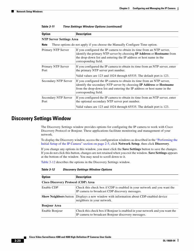
Discovery Settings WindowThe Discovery Settings window provides options for configuring the IP camera to work with Cisco Discovery Protocol or Bonjour. These applications facilitate monitoring and management of your network.
To display the Discovery window, access the configuration windows as described in the “Performing the Initial Setup of the IP Camera” section on page 2-5, click Network Setup, then click Discovery.
If you change any options in this window, you must click the Save Settings button to save the changes. If you do not click this button, changes are not retained when you exit the window. Save Settings appears at the bottom of the window. You may need to scroll down to it.
Table 3-12 describes the options in the Discovery Settings window.
NTP Server Settings Area
Note These options do not apply if you choose the Manually Configure Time option.
Primary NTP Server If you configured the IP camera to obtain its time from an NTP server, identify the primary NTP server by choosing IP Address or Hostname from the drop-down list and entering the IP address or host name in the corresponding field.
Primary NTP Server Port
If you configured the IP camera to obtain its time from an NTP server, enter the primary NTP server port number.
Valid values are 123 and 1024 through 65535. The default port is 123.
Secondary NTP Server If you configured the IP camera to obtain its time from an NTP server, identify the secondary NTP server by choosing IP Address or Hostname from the drop-down list and entering the IP address or host name in the corresponding field.
Secondary NTP Server Port
If you configured the IP camera to obtain its time from an NTP server, enter the optional secondary NTP server port number.
Valid values are 123 and 1024 through 65535. The default port is 123.
Table 3-11 Time Settings Window Options (continued)
Option Description
Table 3-12 Discovery Settings Window Options
Option Description
Cisco Discovery Protocol (CDP) Area
Enable CDP Check this check box if CDP is enabled in your network and you want the IP camera to broadcast CDP discovery messages.
Show Neighbors button Displays a new window with information about CDP-enabled device neighbors in your network.
Bonjour Area
Enable Bonjour Check this check box if Bonjour is enabled in your network and you want the IP camera to broadcast Bonjour discovery messages.
3-20Cisco Video Surveillance 4300 and 4500 High-Definition IP Cameras User Guide
OL-19609-04
Chapter 3 Configuring and Managing the IP CameraNetwork Setup Windows
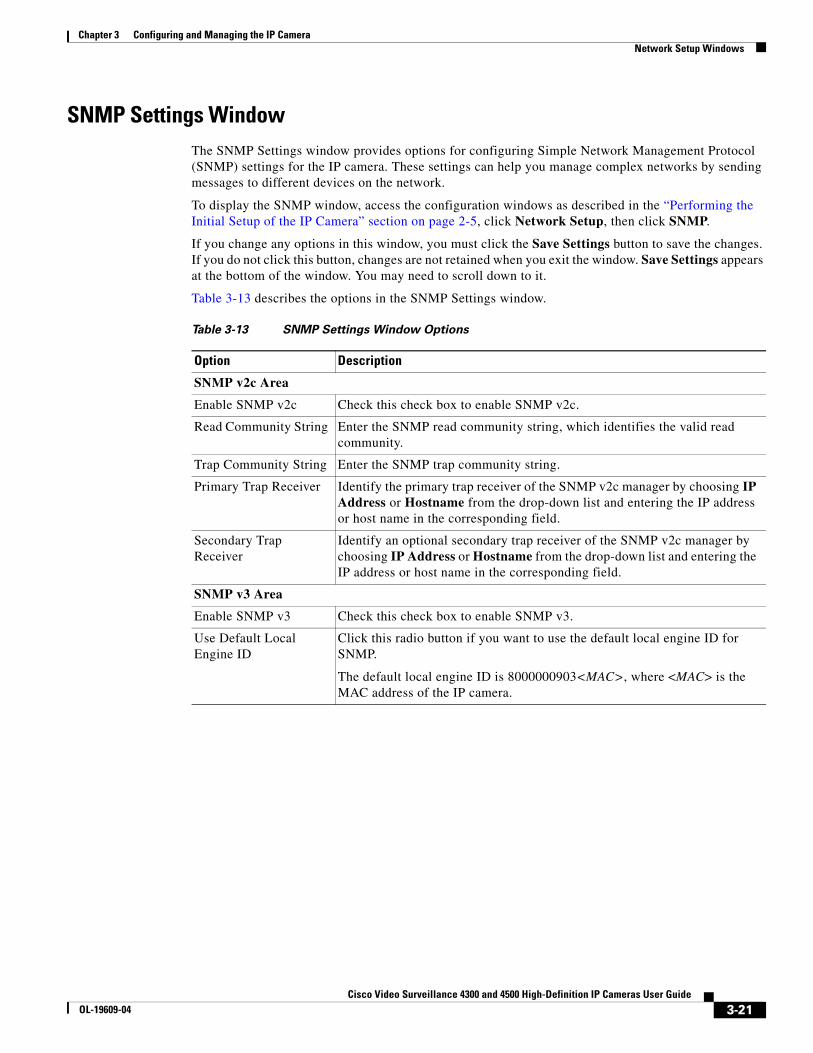
SNMP Settings WindowThe SNMP Settings window provides options for configuring Simple Network Management Protocol (SNMP) settings for the IP camera. These settings can help you manage complex networks by sending messages to different devices on the network.
To display the SNMP window, access the configuration windows as described in the “Performing the Initial Setup of the IP Camera” section on page 2-5, click Network Setup, then click SNMP.
If you change any options in this window, you must click the Save Settings button to save the changes. If you do not click this button, changes are not retained when you exit the window. Save Settings appears at the bottom of the window. You may need to scroll down to it.
Table 3-13 describes the options in the SNMP Settings window.
Table 3-13 SNMP Settings Window Options
Option Description
SNMP v2c Area
Enable SNMP v2c Check this check box to enable SNMP v2c.
Read Community String Enter the SNMP read community string, which identifies the valid read community.
Trap Community String Enter the SNMP trap community string.
Primary Trap Receiver Identify the primary trap receiver of the SNMP v2c manager by choosing IP Address or Hostname from the drop-down list and entering the IP address or host name in the corresponding field.
Secondary Trap Receiver
Identify an optional secondary trap receiver of the SNMP v2c manager by choosing IP Address or Hostname from the drop-down list and entering the IP address or host name in the corresponding field.
SNMP v3 Area
Enable SNMP v3 Check this check box to enable SNMP v3.
Use Default Local Engine ID
Click this radio button if you want to use the default local engine ID for SNMP.
The default local engine ID is 8000000903<MAC>, where <MAC> is the MAC address of the IP camera.
3-21Cisco Video Surveillance 4300 and 4500 High-Definition IP Cameras User Guide
OL-19609-04

Chapter 3 Configuring and Managing the IP CameraNetwork Setup Windows
Manually Configure Local Engine ID
Click this radio button if you want to enter a local engine ID manually, then enter a unique local engine ID.
Enter this information in a standard format as defined in RFC3411. Valid formats include (but are not limited to) the following:
• 8000000903<MAC>
where <MAC> is the MAC address of the IP camera. For example, if the IP camera MAC address is 00:04:9F:11:22:33, enter 800000090300049F112233. This format is the default.
• 8000000901<IPv4_address_hex>
where <IPv4_address_hex> is the IPv4 address of the IP camera in hexadecimal format. For example, if the IP camera IPv4 address is 192.168.0.100, enter 8000000901C0A80064.
• 8000000904<text>
where <text> is a string of up to 54 characters.
Primary Trap Receiver Identify the primary trap receiver of the SNMP v3 manager by choosing IP Address or Hostname from the drop-down list and entering the IP address or host name in the corresponding field.
Secondary Trap Receiver
Identify an optional secondary trap receiver of the SNMP v3 manager by choosing IP Address or Hostname from the drop-down list and entering the IP address or host name in the corresponding field.
User # Display only. Lists the user number of each IP camera user who is configured with the administrator privilege level.
User Name Display only. Displays the name that is associated with the corresponding user number
Authentication Method Choose the authentication protocol for SNMP v3 messages that are sent on behalf of the corresponding user.
Authentication Password
Enter a password for the authentication protocol for SNMP v3 messages that are sent on behalf of the corresponding user.
This password can contain from 8 to 63 characters, which can be letters, numbers, and special characters, but no spaces. Special characters are: ! $ ( ) - . @ ^ _ ` { } ~
Privacy Method Choose DES if you want to use this privacy method for SNMP v3 messages that are sent on behalf of the corresponding user.
If you do not want to use a privacy method, choose None.
Privacy Password If you choose a privacy method, enter a password for SNMP v3 messages that are sent on behalf of the corresponding user.
This password can contain from 8 to 63 characters, which can be letters, numbers, and special characters, but no spaces. Special characters are: ! $ ( ) - . @ ^ _ ` { } ~
Table 3-13 SNMP Settings Window Options (continued)
Option Description
3-22Cisco Video Surveillance 4300 and 4500 High-Definition IP Cameras User Guide
OL-19609-04

Chapter 3 Configuring and Managing the IP CameraNetwork Setup Windows
802.1x Settings WindowThe 802.1x Settings window provides options for configuring 802.1x authentication for the IP camera. These settings require that RADIUS be configured on your network to provide the client authentication.
To display the 802.1x Settings window, access the configuration windows as described in the “Performing the Initial Setup of the IP Camera” section on page 2-5, click Network Setup, then click 802.1x (RADIUS).
If you change any options in this window, you must click the Save Settings button to save the changes. If you do not click this button, changes are not retained when you exit the window. Save Settings appears at the bottom of the window. You may need to scroll down to it.
Table 3-14 describes the options in the 802.1x Settings window.
Table 3-14 802.1x Settings Window Options
Option Description
802.1x Settings Area
Enable 802.1x Check this check box to enable 802.1x authentication for the IP camera.
Protocol Type Choose the protocol for 802.1x authentication. Options are EAP-TLS, EAP-TTLS, EAP-PEAP, and EAP-FAST.
The remaining fields in this window change depending on the protocol type that you choose.
EAP-TLS Configuration Options
Note These options appear if you select the protocol type EAP-TLS.
User Name Enter the user name that the IP camera uses to access the RADIUS server.
Device (Client) Certificate
Path and folder where the device certificate for the IP camera is stored. You can click Browse to find this location.
After you enter this information, click Upload to upload the certificate to the IP camera.
Password (for Private Key)
If the private key in the device certificate is password protected, enter the password that is required to unlock the private key.
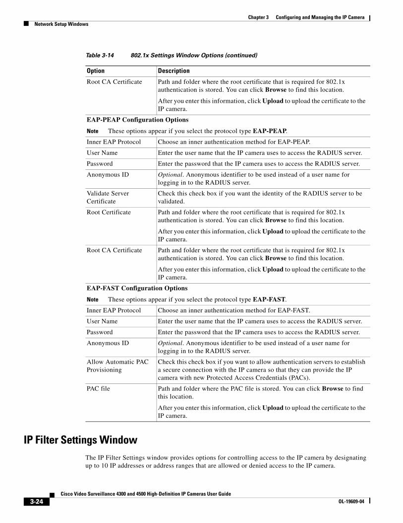
Root CA Certificate Path and folder where the root certificate that is required for 802.1x authentication is stored. You can click Browse to find this location.
After you enter this information, click Upload to upload the certificate to the IP camera.
EAP-TTLS Configuration Options
Note These options appear if you select the protocol type EAP-TTLS.
Inner Authentication Choose an inner authentication method for EAP-TTLS. Options are MS-CHAP, MS-CHAP v2, PEAP, and EAP-MDS.
User Name Enter the user name that the IP camera uses to access the RADIUS server.
Password Enter the password that the IP camera uses to access the RADIUS server.
Anonymous ID Optional. Unsigned public identifier to be used instead of a user name for logging in to the RADIUS server.
Validate Server Certificate
Check this check box if you want the identity of the RADIUS server to be validated.
3-23Cisco Video Surveillance 4300 and 4500 High-Definition IP Cameras User Guide
OL-19609-04
Chapter 3 Configuring and Managing the IP CameraNetwork Setup Windows
IP Filter Settings WindowThe IP Filter Settings window provides options for controlling access to the IP camera by designating up to 10 IP addresses or address ranges that are allowed or denied access to the IP camera.
Root CA Certificate Path and folder where the root certificate that is required for 802.1x authentication is stored. You can click Browse to find this location.
After you enter this information, click Upload to upload the certificate to the IP camera.
EAP-PEAP Configuration Options
Note These options appear if you select the protocol type EAP-PEAP.
Inner EAP Protocol Choose an inner authentication method for EAP-PEAP.
User Name Enter the user name that the IP camera uses to access the RADIUS server.
Password Enter the password that the IP camera uses to access the RADIUS server.
Anonymous ID Optional. Anonymous identifier to be used instead of a user name for logging in to the RADIUS server.
Validate Server Certificate
Check this check box if you want the identity of the RADIUS server to be validated.
Root Certificate Path and folder where the root certificate that is required for 802.1x authentication is stored. You can click Browse to find this location.
After you enter this information, click Upload to upload the certificate to the IP camera.
Root CA Certificate Path and folder where the root certificate that is required for 802.1x authentication is stored. You can click Browse to find this location.
After you enter this information, click Upload to upload the certificate to the IP camera.
EAP-FAST Configuration Options
Note These options appear if you select the protocol type EAP-FAST.
Inner EAP Protocol Choose an inner authentication method for EAP-FAST.
User Name Enter the user name that the IP camera uses to access the RADIUS server.
Password Enter the password that the IP camera uses to access the RADIUS server.
Anonymous ID Optional. Anonymous identifier to be used instead of a user name for logging in to the RADIUS server.
Allow Automatic PAC Provisioning
Check this check box if you want to allow authentication servers to establish a secure connection with the IP camera so that they can provide the IP camera with new Protected Access Credentials (PACs).
PAC file Path and folder where the PAC file is stored. You can click Browse to find this location.
After you enter this information, click Upload to upload the certificate to the IP camera.
Table 3-14 802.1x Settings Window Options (continued)
Option Description
3-24Cisco Video Surveillance 4300 and 4500 High-Definition IP Cameras User Guide
OL-19609-04

Chapter 3 Configuring and Managing the IP CameraNetwork Setup Windows
To display the IP Filtering window, access the configuration windows as described in the “Performing the Initial Setup of the IP Camera” section on page 2-5, click Network Setup, then click IP Filtering.
If you change any options in this window, you must click the Save Settings button to save the changes. If you do not click this button, changes are not retained when you exit the window. Save Settings appears at the bottom of the window. You may need to scroll down to it.
Table 3-15 describes the options in the IP Filter Settings window.
QoS Settings WindowThe QoS Settings window provides options for configuring quality of service (QoS) settings for audio/video streams.
To display the QoS Settings window, access the configuration windows as described in the “Performing the Initial Setup of the IP Camera” section on page 2-5, click Network Setup, then click IP Filtering.
If you change any options in this window, you must click the Save Settings button to save the changes. If you do not click this button, changes are not retained when you exit the window. Save Settings appears at the bottom of the window. You may need to scroll down to it.
Table 3-16 describes the options in the QoS Settings window.
Table 3-15 IP Filter Settings Window Options
Option Description
IP Filter Area
Enable IP Filtering Check this check box to cause the IP camera to allow or deny access to IP addresses as configured in the IP Filtering window.
Filter Entries Area
# Display only. Filter number.
Action Choose an action for the corresponding IP address or address range:
• Deny—IP address or address range cannot access the IP camera
• Allow—IP address or address range can access the IP camera
IP Address/Bit Mask Enter the IP address and bit mask to which the corresponding action applies.
Make these entries in Classless Inter-Domain Routing (CIDR) notation. CIDR is defined in RFC 4632.
Table 3-16 QoS Settings Window Options
Option Description
Class of Service (CoS) Area
Enable CoS for Video Streaming
Check this check box to enable class of service (CoS) control for video streams.
If you enable this option, the IP camera specifies a VLAN tag that appends to an Ethernet MAC frame for video streaming data.
Video Priority Value from 0 (lowest priority) through 7 (highest priority) that specifies the CoS priority value for steaming video data.
Video VLAN ID Enter the ID of the video VLAN to which CoS packets are directed.
3-25Cisco Video Surveillance 4300 and 4500 High-Definition IP Cameras User Guide
OL-19609-04

Chapter 3 Configuring and Managing the IP CameraAdministration Windows
Administration WindowsThe Administrator windows lets you perform several general administrative operations, including enabling HTTP and HTTPS access to the IP camera, configuring users, resetting or rebooting the IP camera, and updating firmware.
The following sections describe the Administration windows in detail:
• Account Initialization Window, page 3-26
• User Settings Window, page 3-28
• Maintenance Settings Window, page 3-29
• Firmware Settings Window, page 3-31
• Device Processes Window, page 3-32
• Password Complexity Window, page 3-33
Account Initialization WindowThe Account Initialization window provides options for configuring passwords for the IP camera default administrator accounts, and for configuring which protocols can be used to access the IP camera.
The IP camera always has an HTTP/HTTPS administrator who can access the IP camera through an HTTP or HTTPS connection. The name of this administrator is admin. The password is configurable.
If you want to access the IP camera through SSH, you must configure a password for an SSH administrator. The name of this administrator is root. The password is configurable.
Enable CoS for Audio Streaming
Check this check box to enable class of service (CoS) control for audio streams.
Audio Priority Value from 0 (lowest priority) through 7 (highest priority) that specifies the CoS priority value for steaming audio data.
Audio VLAN ID Enter the ID of the audio VLAN to which CoS packets are directed.
Differentiated Services (DiffServ) Area
Enable DiffServ for Video Streaming
Check this check box to enable Differentiated Services (DiffServ) for video streams.
If you enable this option, the IP camera specifies the DSCP priority value that appends to an IP header for video streaming packets.
Video DSCP Priority Value
Value from 0 (lowest priority) through 63 (highest priority) that specifies the DSCP priority value for steaming video data.
Enable DiffServ for Audio Streaming
Check this check box to enable Differentiated Services (DiffServ) for audio streams.
Audio DSCP Priority Value
Value from 0 (lowest priority) through 63 (highest priority) that specifies the DSCP priority value for steaming audio data.
Table 3-16 QoS Settings Window Options (continued)
Option Description
3-26Cisco Video Surveillance 4300 and 4500 High-Definition IP Cameras User Guide
OL-19609-04

Chapter 3 Configuring and Managing the IP CameraAdministration Windows
To display the Account Initialization window, access the configuration windows as described in the “Performing the Initial Setup of the IP Camera” section on page 2-5, click Administration, then click Initialization.
If you change any options in this window, you must click the Save Settings button to save the changes. If you do not click this button, changes are not retained when you exit the window. Save Settings appears at the bottom of the window. You may need to scroll down to it.
Table 3-17 describes the options in the Account Initialization window.
Table 3-17 Account Initialization Window Options
Option Description
Administrator Accounts Area
Protocol Display only. Indicates the protocol that the corresponding administrator can use to access the IP camera: HTTP/HTTPS or SSH.
User Name Display only. Indicates the default user name for the corresponding administrator: admin or root
Password Enter a password for the corresponding administrator. The password is case sensitive and must contain from 8 to 32 characters, which can be letters, numbers, and special characters, but no spaces. Special characters are: ! $ ( ) - . @ ^ _ ` { } ~
Confirm password Re-enter the password for the corresponding administrator.
Access Protocols Area
Enable HTTP Check this check box if you want to allow HTTP connections to the IP camera.
HTTP Port Enter the HTTP port that is used to access the IP camera. Valid port numbers are 80 and 1024 through 32767. The default port is 80.
If you configure the HTTP port to a value other than 80, you must specify the port number in the URL for the IP camera when you access it through an HTTP connection. For example, if the IP address of the IP camera is 192.168.1.100 and the HTTP port is 1024, enter this URL for the IP camera: http://192.168.1.100:1024.
Enable HTTPS Check this check box if you want to allow HTTPS connections to the IP camera.
HTTPS Port Enter the HTTPS port that is used to access the IP camera. Valid port numbers are 443 and 1024 through 65535. The default port is 443.
If you configure the HTTPS port to a value other than 443, you must specify the port number in the URL for the IP camera when you access it through an HTTPS connection. For example, if the IP address of the IP camera is 192.168.1.100 and the HTTPS port is 1024, enter this URL for the IP camera: https://192.168.1.100:1024.
Enable Secure Shell (SSH)
Check this check box if you want to allow access to the camera through a SSH connection.
Secure Shell (SSH) Port Enter the SSH port that is used to access the IP camera. Valid port numbers are 22 and 1024 through 65535. The default port is 22.
3-27Cisco Video Surveillance 4300 and 4500 High-Definition IP Cameras User Guide
OL-19609-04

Chapter 3 Configuring and Managing the IP CameraAdministration Windows
User Settings WindowThe User Settings window lets you configure the following types of IP camera users:
• Administrator—Can access all IP camera windows, features, and functions.
• Viewer—Can access only the Camera Video/Control window and all features in that window except:
– Video image controls
– Set Current Preset as Home button
– Add Preset Position button
– Deleted Selected Preset button
– Pan/tilt speed controls
– Motion detection controls
There is always at least one user with Administrator privileges configured. The user name of this user is “admin.” You can configure up to four additional users and assign privilege levels to each one.
When you configure users, follow these guidelines:
• After you enter a name, password, and privilege level for a user, click Add next to the user information to save your changes.
• To change the password for an existing user, click Change next to the user name.
• To remove a user, click Delete next to the user. If you delete a user who is logged into the IP camera, the user remains logged in and can continue access the IP camera.
• To change the name of a user, you must delete the user then create a new user.
To display the User Settings window, access the configuration windows as described in the “Performing the Initial Setup of the IP Camera” section on page 2-5, click Administration, then click Users.
Table 3-18 describes the options in the User Settings window.
Table 3-18 User Settings Window Options
Option Description
User List Area
User Name Enter a unique name for the user.
The user name is case sensitive and can include up to 64 letters, numbers, and special characters, but no spaces. Special characters are: ! % ( ) + , - = @ _ ~
There is always one user named admin (all lower case), which cannot be deleted.
Password Enter a password for the user.
The password is case sensitive and must contain from 8 to 32 characters, which can be letters, numbers, and special characters, but no spaces. Special characters are: ! $ ( ) - . @ ^ _ ` { } ~
Confirm Password Re-enter the password for the user.
3-28Cisco Video Surveillance 4300 and 4500 High-Definition IP Cameras User Guide
OL-19609-04

Chapter 3 Configuring and Managing the IP CameraAdministration Windows
Maintenance Settings WindowThe Maintenance Settings window provides options for setting or restarting the IP camera, saving configuration information from the IP camera, and uploading the configuration information to the IP camera.
Saving and uploading configuration is useful for these activities:
• Configuring multiple IP cameras—If your network includes several IP cameras that should have similar configurations, you can configure one IP camera, save that configuration, and upload it to other IP cameras. Then, instead of manually configuring all options on each IP camera, you manually configure only the options that are unique, such as the IP address, if not obtained from DHCP.
• Backing up configuration—If you save the configuration from the IP camera, you can upload it to the IP camera to restore the configuration if it is lost, or if you can upload it to a replacement IP camera, if needed.
To display the Maintenance Settings window, access the configuration windows as described in the “Performing the Initial Setup of the IP Camera” section on page 2-5, click Administration, then click Maintenance.
If you change any options in this window, you must click the Save Settings button to save the changes. If you do not click this button, changes are not retained when you exit the window. Save Settings appears at the bottom of the window. You may need to scroll down to it.
Table 3-19 describes the options in the Maintenance Settings window.
Privilege Level Select the desired privilege level for the user:
• Administrator—Can access all IP camera windows, features, and functions.
• Viewer—Can access the Camera Video/Control window with limited controls, and can access the Refresh, Logout, About, and Help links from that window.
Change button Click this button to change the password of the corresponding user.
Add button Click this button to add the corresponding user. That user can then log in to the IP camera.
Delete button Click this button to remove the corresponding user. This user can no longer log in to the IP camera.
Table 3-18 User Settings Window Options (continued)
Option Description
3-29Cisco Video Surveillance 4300 and 4500 High-Definition IP Cameras User Guide
OL-19609-04
Chapter 3 Configuring and Managing the IP CameraAdministration Windows
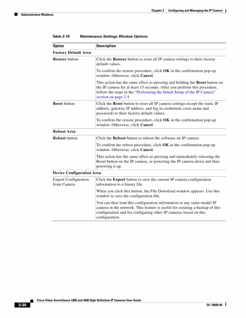
Table 3-19 Maintenance Settings Window Options
Option Description
Factory Default Area
Restore button Click the Restore button to reset all IP camera settings to their factory default values.
To confirm the restore procedure, click OK in the confirmation pop-up window. Otherwise, click Cancel.
This action has the same effect as pressing and holding the Reset button on the IP camera for at least 15 seconds. After you perform this procedure, follow the steps in the “Performing the Initial Setup of the IP Camera” section on page 2-5.
Reset button Click the Reset button to reset all IP camera settings except the static IP address, gateway IP address, and log in credentials (user name and password) to their factory default values.
To confirm the restore procedure, click OK in the confirmation pop-up window. Otherwise, click Cancel.
Reboot Area
Reboot button Click the Reboot button to reboot the software on IP camera.
To confirm the reboot procedure, click OK in the confirmation pop-up window. Otherwise, click Cancel.
This action has the same effect as pressing and immediately releasing the Reset button on the IP camera, or powering the IP camera down and then powering it up.
Device Configuration Area
Export Configuration from Camera
Click the Export button to save the current IP camera configuration information to a binary file.
When you click this button, the File Download window appears. Use this window to save the configuration file.
You can then load this configuration information to any same-model IP camera in the network. This feature is useful for creating a backup of this configuration and for configuring other IP cameras based on this configuration.
3-30Cisco Video Surveillance 4300 and 4500 High-Definition IP Cameras User Guide
OL-19609-04

Chapter 3 Configuring and Managing the IP CameraAdministration Windows
Firmware Settings WindowThe Firmware Settings window lets you view information about the firmware that is installed on the IP camera and upgrade the firmware.
Before you upgrade firmware, download the firmware file to a PC that is accessible on your network and unzip the file if it is zipped. To download firmware, go to this web page:
http://www.cisco.com/en/US/products/ps6918/Products_Sub_Category_Home.html
After you upgrade firmware, the IP camera restarts automatically. It retains all configuration information.
To display the Firmware Settings window, access the configuration windows as described in the “Performing the Initial Setup of the IP Camera” section on page 2-5, click Administration, then click Firmware.
If you change any options in this window, you must click the Save Settings button to save the changes. If you do not click this button, changes are not retained when you exit the window. Save Settings appears at the bottom of the window. You may need to scroll down to it.
Table 3-20 describes the options in the Firmware Settings window.
Import configuration to camera
Path and folder where a configuration file is stored. You can click Browse to find this location. After you enter this information, click Import to load the configuration file to the IP camera.
After you upload a configuration file to the IP camera, the IP camera restarts automatically.
If you upload configuration from another IP camera that is active in your network, make sure to configure this IP camera with a name, description, and unique IP address (if not obtained through DHCP). To change these options, see the “Basic Settings Window” section on page 3-16 and the “IP Addressing Window” section on page 3-17.
A configuration file that you upload includes the passwords that are configured for the administrator and for users. If you change any passwords after saving the configuration file, be aware that uploading the file overwrites the new passwords with the saved ones.
Table 3-19 Maintenance Settings Window Options (continued)
Option Description
Table 3-20 Firmware Settings Window Options
Option Description
Device Information Area
IP Address Display only. IP address of the IP camera
MAC Address Display only. MAC address of the IP camera.
Device Name Display only. ID of the IP camera, as configured in the Basic Settings window. For more information, see the “Basic Settings Window” section on page 3-16.
3-31Cisco Video Surveillance 4300 and 4500 High-Definition IP Cameras User Guide
OL-19609-04
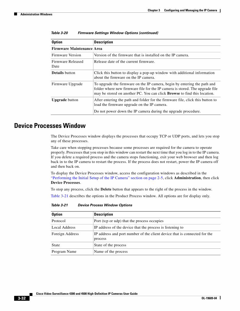
Chapter 3 Configuring and Managing the IP CameraAdministration Windows
Device Processes WindowThe Device Processes window displays the processes that occupy TCP or UDP ports, and lets you stop any of these processes.
Take care when stopping processes because some processes are required for the camera to operate properly. Processes that you stop in this window can restart the next time that you log in to the IP camera. If you delete a required process and the camera stops functioning, exit your web browser and then log back in to the IP camera to restart the process. If the process does not restart, power the IP camera off and then back on.
To display the Device Processes window, access the configuration windows as described in the “Performing the Initial Setup of the IP Camera” section on page 2-5, click Administration, then click Device Processes.
To stop any process, click the Delete button that appears to the right of the process in the window.
Table 3-21 describes the options in the Product Process window. All options are for display only.
Firmware Maintenance Area
Firmware Version Version of the firmware that is installed on the IP camera.
Firmware Released Date
Release date of the current firmware.
Details button Click this button to display a pop-up window with additional information about the firmware on the IP camera.
Firmware Upgrade To upgrade the firmware on the IP camera, begin by entering the path and folder where new firmware file for the IP camera is stored. The upgrade file may be stored on another PC. You can click Browse to find this location.
Upgrade button After entering the path and folder for the firmware file, click this button to load the firmware upgrade on the IP camera.
Do not power down the IP camera during the upgrade procedure.
Table 3-20 Firmware Settings Window Options (continued)
Option Description
Table 3-21 Device Process Window Options
Option Description
Protocol Port (tcp or udp) that the process occupies
Local Address IP address of the device that the process is listening to
Foreign Address IP address and port number of the client device that is connected for the process
State State of the process
Program Name Name of the process
3-32Cisco Video Surveillance 4300 and 4500 High-Definition IP Cameras User Guide
OL-19609-04
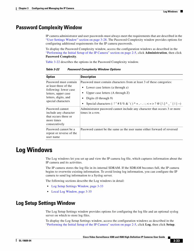
Chapter 3 Configuring and Managing the IP CameraLog Windows
Password Complexity WindowIP camera administrator and user passwords must always meet the requirements that are described in the “User Settings Window” section on page 3-28. The Password Complexity window provides options for configuring additional requirements for the IP camera passwords.
To display the Password Complexity window, access the configuration windows as described in the “Performing the Initial Setup of the IP Camera” section on page 2-5, click Administration, then click Password Complexity.
Table 3-22 describes the options in the Password Complexity window.
Log WindowsThe Log windows let you set up and view the IP camera log file, which captures information about the IP camera and its activities.
The IP camera stores the log file in its internal SDRAM. If the SDRAM becomes full, the IP camera begins to overwrite existing information. To avoid losing log information, you can configure the IP camera to send log information to a Syslog server.
The following sections describe the Log windows in detail:
• Log Setup Settings Window, page 3-33
• Local Log Window, page 3-35
Log Setup Settings WindowThe Log Setup Settings window provides options for configuring the log file and an optional syslog server on which to store log files.
To display the Log Setup Settings window, access the configuration windows as described in the “Performing the Initial Setup of the IP Camera” section on page 2-5, click Log, then click Setup.
Table 3-22 Password Complexity Window Options
Option Description
Password must contain at least three of the following: lower case letters, upper case letters, digits, and special characters
Password must contain characters from at least 3 of these categories:
• Lower case letters (a through z)
• Upper case letters (A through Z)
• Digits (0 through 9)
• Special characters (: ! " # $ % & ' ( ) * + , - . : ; < = > ? @ [ \ ] ^ _ ` { | } ~)
Password cannot include any character that occurs three or more times consecutively
Administrator password cannot include any character that occurs 3 or more times in a row.
Password cannot be a repeat or reverse of the user name
Password cannot be the same as the user name either forward of reversed
3-33Cisco Video Surveillance 4300 and 4500 High-Definition IP Cameras User Guide
OL-19609-04

Chapter 3 Configuring and Managing the IP CameraLog Windows
If you change any options in this window, you must click the Save Settings button to save the changes. If you do not click this button, changes are not retained when you exit the window. Save Settings appears at the bottom of the window. You may need to scroll down to it.
Table 3-23 describes the options in the Log Setup Settings window.
Table 3-23 Log Setup Settings Window Options
Option Description
Local Log Settings Area
Minimum Log Severity Choose the minimum severity of messages that the appear in the log file. The system logs all messages of this severity and higher. Message severities, from highest to lowest, are:
• Emergency—The system is unusable.
• Alert—A situation occurred that requires immediate action.
• Critical—A situation occurred that requires action soon.
• Error—An error occurred, but it does not necessarily affects the ability of the system to function.
• Warning—A undesirable condition occurred.
• Notice—Notification about a system condition that is not necessarily an error condition.
• Informational—Information about a system activity.
• Debug—Information about a system activity with detailed technical information. Includes messages of every other severity.
The default severity is Informational.
Maximum Log Entries Maximum number of entries that the log file maintains. When the log file reaches this limit, it begins overwriting entries, starting with the oldest one.
The default value is 100.
Syslog Settings Area
Enable Syslog Check this check box to send the log information to a designated Syslog server. The selected information also is maintained on the IP camera until it is overwritten.
This option is useful for consolidating logs in deployments with several IP cameras and for retaining logs.
Primary Syslog Server Identify the primary Syslog server by choosing IP Address or Hostname from the drop-down list and entering the IP address or host name in the corresponding field.
Primary Syslog Server Port
Enter the primary Syslog server port number that receives the logs.
Valid values are 514 and 1024 through 65535. The default Syslog port is 514.
Facility Enter the system facility that receives logs on the Syslog server.
3-34Cisco Video Surveillance 4300 and 4500 High-Definition IP Cameras User Guide
OL-19609-04

Chapter 3 Configuring and Managing the IP CameraLog Windows
Local Log WindowThe Local Log window lets you view the log file that is stored on the IP camera.
Minimum Log Severity Choose the minimum severity of messages that are sent to the Syslog server. The system sends all messages of this severity and higher. Message severities, from highest to lowest, are:
• Emergency—The system is unusable.
• Alert—A situation occurred that requires immediate action.
• Critical—A situation occurred that requires action soon.
• Error—An error occurred, but it does not necessarily affects the ability of the system to function.
• Warning—A undesirable condition occurred.
• Notice—Notification about a system condition that is not an error condition.
• Informational—Information about a system activity.
• Debug—Information about a system activity with detailed technical information. Includes messages of every other severity.
The default severity is Informational.
Secondary Syslog Server
Identify an optional secondary Syslog server by choosing IP Address or Hostname from the drop-down list and entering the IP address or host name in the corresponding field.
Secondary Syslog Server Port
Enter the port number that receives the logs on the secondary Syslog server.
Valid values are 514 and 1024 through 65535. The default Syslog port is 514.
Facility Enter the system facility that receives logs on the Syslog server.
Minimum Log Severity Choose the minimum severity of messages that are sent to the secondary Syslog server. The system sends all messages of this severity and higher. Message severities, from highest to lowest, are:
• Emergency—The system is unusable.
• Alert—A situation occurred that requires immediate action.
• Critical—A situation occurred that requires action soon.
• Error—An error occurred, but it does not necessarily affect the ability of the system to function.
• Warning—An undesirable condition occurred.
• Notice—Notification about a system condition that is not an error condition.
• Informational—Information about a system activity.
• Debug—Information about a system activity with detailed technical information. Includes messages of every other severity.
Table 3-23 Log Setup Settings Window Options (continued)
Option Description
3-35Cisco Video Surveillance 4300 and 4500 High-Definition IP Cameras User Guide
OL-19609-04

Chapter 3 Configuring and Managing the IP CameraLog Windows
To display the Local Log window, access the configuration windows as described in the “Performing the Initial Setup of the IP Camera” section on page 2-5, click Log, then click Local Log.
Table 3-24 describes the options in the Local Log window.
Table 3-24 Local Log Window Options
Option Description
Log List Area
Rows per page Choose the number of log entry rows to display per page and click the Go button to the right of this option to update the display.
Filter Choose the type of log message to include in the display.
To include messages of every severity, choose All.
Since Choose the time period for which you want to view log messages.
Go button Update the log display based on the values in the Filter and Since fields.
Severity An icon in this column indicates the severity of the corresponding log message:
—Emergency message
—Alert message
—Critical message
—Error message
—Warning message
—Notice message
—Informational message
—Debug message
To display log messages in order of severity with the least severity first, click the Severity column heading. Click the heading again to reverse the display order.
Date/Time Date and time that the logged activity occurred.
By default, log messages appear in the order that the activity occurred with the oldest message first. To reverse this display order, click the Date/Time column heading.
Description Message that describes the logged activity. For detailed information about log messages, see Table 3-25 on page 3-37.
Page controls Let you move through the log file entries:
Page field—Enter a page number and press Enter.
—Go to first page
—Go to previous page
—Go to next page
—Go to last page
3-36Cisco Video Surveillance 4300 and 4500 High-Definition IP Cameras User Guide
OL-19609-04

Chapter 3 Configuring and Managing the IP CameraLog Windows
Table 3-25 describes the messages that can appear in the IP camera log file. When you view the log file, each message includes the date and time that it was logged. In this table:
• Messages appear in alphabetical order
• Angle brackets (<>) indicate items that are replaced by appropriate information when the message appears. Italic text describes these items.
• Severity indicates the severity of the message:
– 0—Emergency (the system is unusable)
– 1—Alert (a situation occurred that requires immediate action)
– 2—Critical (a situation occurred that requires action soon)
– 3—Error (an error occurred, but it does not necessarily affect the ability of the system to function)
– 4—Warning (an undesirable condition occurred)
– 5—Notice (notification about a system condition that is not an error condition)
– 6—Informational (information about a system activity)
– 7—Debug (information about a system activity with detailed technical information)
Table 3-25 Log Messages
Message Name Description that Appears in Log File Explanation Severity
AUTHENTICATION_FAILED Access authentication to <web server, streaming server, or SSH server> by user <user> <IP address or hostname> failed.
An attempt to log in or authenticate to the IP camera failed.
3
AUTHENTICATION_FAILED Access authentication to <server type> server <server IP address or hostname> failed.
The IP camera was unable to access an SNTP, Syslog, DNS, SMTP, HTTP, or 802.1x server.
4
AUTHORIZATION_FAILED Unauthorized address <IP address or hostname> attempted to access camera.
An attempt was made to access the IP camera by using invalid user credentials for from an IP address that has been configured for no access.
3
CODEC_LOST Connection to Codec/Sensor module was lost. Internal module is either down or not responding.
The IP camera codec/sensor module is not responding.
4
CONFIG_SAVE_FAILED Saving configuration to user <user> <IP address or hostname> failed.
A user attempt to save the IP camera configuration failed.
3
CONFIG_SAVED Configuration saved by user <user> <IP address or hostname>.
The IP camera configuration was saved by a user.
5
CONFIG_UPLOAD_FAILED Uploading configuration failed from user <user> <IP address or hostname>.
A user attempt to import the IP camera configuration failed.
3
CONFIG_UPLOADED Configuration uploaded from user <user> <IP address or hostname>.
The IP camera configuration was imported by a user.
5
DEFAULTS_FAILED Restoring factory defaults failed for user <user> <IP address or hostname>.
An attempt to reset the IP camera to its factory default configuration failed.
3
3-37Cisco Video Surveillance 4300 and 4500 High-Definition IP Cameras User Guide
OL-19609-04
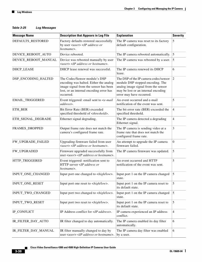
Chapter 3 Configuring and Managing the IP CameraLog Windows
DEFAULTS_RESTORED Factory defaults restored successfully by user <user> <IP address or hostname>.
The IP camera was reset to its factory default configuration.
5
DEVICE_REBOOT_AUTO Device rebooted. The IP camera rebooted automatically. 5
DEVICE_REBOOT_MANUAL Device was rebooted manually by user <user> <IP address or hostname>.
The IP camera was rebooted by a user. 5
DHCP_LEASE DHCP lease renewal was successful. The IP camera renewed its DHCP lease.
6
DSP_ENCODING_HALTED The Codec/Sensor module’s DSP encoding was halted. Either the analog image signal from the sensor has been lost, or an internal encoding error has occurred.
The DSP of the IP camera codec/sensor module DSP stopped encoding. The analog image signal from the sensor may be lost or an internal encoding error may have occurred.
2
EMAIL_TRIGGERED Event triggered: email sent to <e-mail address>.
An event occurred and e-mail notification of the event was sent.
5
ETH_BER Bit Error Rate (BER) exceeded specified threshold of <threshold>.
The bit error rate (BER) exceeded the specified threshold.
4
ETH_SIGNAL_DEGRADE Ethernet signal degrading. The IP camera detected a degrading Ethernet signal.
4
FRAMES_DROPPED Output frame rate does not match the camera’s configured frame rate.
The IP camera is sending video at a frame rate that does not match the configured frame rate.
3
FW_UPGRADE_FAILED Upgrading firmware failed from user <user> <IP address or hostname>.
An attempt to upgrade the IP camera firmware failed.
0
FW_UPGRADED Firmware upgraded successfully from user <user> <IP address or hostname>.
The IP camera firmware was updated. 5
HTTP_TRIGGERED Event triggered: notification sent to HTTP server <IP address or hostname>.
An event occurred and HTTP notification of the event was sent.
5
INPUT_ONE_CHANGED Input port one changed to <high/low>. Input port 1 on the IP camera changed state.
5
INPUT_ONE_RESET Input port one reset to <high/low>. Input port 1 on the IP camera reset to its default state.
5
INPUT_TWO_CHANGED Input port two changed to <high/low>. Input port 1 on the IP camera changed state.
5
INPUT_TWO_RESET Input port two reset to <high/low>. Input port 1 on the IP camera reset to its default state.
5
IP_CONFLICT IP Address conflict for <IP address>. IP camera experienced an IP address conflict.
4
IR_FILTER_DAY_AUTO IR filter changed to day automatically. The IP camera enabled its day filter automatically.
6
IR_FILTER_DAY_MANUAL IR filter manually changed to day by user <user> <IP address or hostname>.
The IP camera day filter was enabled by a user.
6
Table 3-25 Log Messages
Message Name Description that Appears in Log File Explanation Severity
3-38Cisco Video Surveillance 4300 and 4500 High-Definition IP Cameras User Guide
OL-19609-04

Chapter 3 Configuring and Managing the IP CameraLog Windows
IR_FILTER_NIGHT_AUTO IR filter changed to night automatically.
The IP camera enabled its night filter automatically.
6
IR_FILTER_NIGHT_MANUAL IR filter changed to night by user <user> <IP address or hostname>.
The IP camera night filter was enabled by a user.
6
LOG_IN User <user> <IP address or hostname> logged in to <web server or SSH server>.
A user logged in to the IP camera. 5
LOG_OUT User <user> <IP address or hostname> logged out of <web server or SSH server>.
A user logged out of the IP camera. 5
MOTION_DETECTED Motion detected in region <region index>.
The IP camera detected motion in its video field.
5
MOTION_STOPPED Motion in region <region index> stopped.
The IP camera stopped detecting motion in its video field.
5
OUTPUT_ONE_RESET Output port one reset to <high/low>. Output port 1 on the IP camera reset to its default state.
5
OUTPUT_ONE_TRIGGERED Output port one triggered to <high/low>.
Output port 1 on the IP camera changed state.
5
OUTPUT_TWO_RESET Output port two reset to <high/low>. Output port 2 on the IP camera reset to its default state.
5
OUTPUT_TWO_TRIGGERED Output port two triggered to <high/low>.
Output port 2 on the IP camera changed state.
5
PAN Pan <left/right> by user <user> <IP address or hostname>.
The IP camera was panned by a user. 6
PATROL_START Patrol started by user <user> <IP address or hostname>.
A patrol sequence was started by a user.
6
PATROL_STOP Patrol stopped by user <user> <IP address or hostname>.
A patrol sequence was stopped by a user.
6
POWER_SUPPLY_FAILURE DC power supply failure. The DC power for the IP camera failed. 2
PTZ_LOST Connection to PTZ device was lost. Device is either down or not responding.
The pan/tilt device that the IP camera is connected to is not responding.
4
SERVER_CONTACTED Communication established with <server type> server <server or IP address>.
The IP camera established communication with an SNTP, DHCP, Syslog, DNS, SMTP, HTTP, or 802.1x server.
6
SERVER_LOST Communication lost with <server type> server <server or IP address>.
The IP camera lost communication with an SNTP, DHCP, Syslog, DNS, SMTP, HTTP, or 802.1x server.
4
SERVER_UNREACHABLE Failed to contact <server type> server <server or IP address>.
The IP camera was unable to contact an SNTP, DHCP, Syslog, DNS, SMTP, HTTP, or 802.1x server or a gateway.
4
Table 3-25 Log Messages
Message Name Description that Appears in Log File Explanation Severity
3-39Cisco Video Surveillance 4300 and 4500 High-Definition IP Cameras User Guide
OL-19609-04

Chapter 3 Configuring and Managing the IP CameraLog Windows
START_STREAM Channel <channel ID> started streaming to user <user> <IP address or hostname>.
The IP camera began streaming video to a user device.
6
STOP_STREAM Channel <channel ID> stopped streaming to user <user> <IP address or hostname>.
The IP camera stopped streaming video to a user device.
6
TEMP_THRESHOLD_T1 Current temperature, <temperature>, <exceeds/is below> <high temperature/ low_temperature> threshold.
The internal temperature of the IP camera is lower than 59°F (15°C) or higher than 149°F (65°C).
2
TEMP_THRESHOLD_T2 Current temperature, <temperature>, <exceeds/is below> <high temperature/ low_temperature> threshold.
The internal temperature of the IP camera is lower than 32°F (0°C) or higher than 176°F (80°C).
4
TEMP_THRESHOLD_T3 Current temperature, <temperature>, <exceeds/is below> <high temperature/ low_temperature> threshold.
The internal temperature of the IP camera is lower than 5°F (–15°C) or higher than 194°F (90°C).
5
TILT Tilt <up/down> by user <user> <IP address or hostname>.
The IP camera was tilted by a user. 6
TIME_DST_SWITCH Time switched to Daylight Savings time with an offset of <offset> minutes.
The IP camera internal clock switched to daylight saving time.
6
TIME_REG_SWITCH Time switched from Daylight Savings time with an offset of <offset> minutes.
The IP camera internal clock switched to standard time.
6
UNEXPECTED_EXCEPTION Unexpected exception occurred. Pan <left/right> failed by user <user> <IP address or hostname>.
An attempt by a user to pan the IP camera failed.
1
UNEXPECTED_EXCEPTION Unexpected exception occurred. Tilt <up/down> failed by user <user> <IP address or hostname>.
An attempt by a user to tilt the IP camera failed.
1
UNEXPECTED_EXCEPTION Unexpected exception occurred. Patrol failed by user <user> <IP address or hostname>.
An attempt by a user to start a patrol sequence failed.
1
UNEXPECTED_EXCEPTION Unexpected exception occurred. Could not <read/write> <to/from> repository by user <user> <IP address or hostname>.
IP camera could not read or write information to its internal repository.
2
Table 3-25 Log Messages
Message Name Description that Appears in Log File Explanation Severity
3-40Cisco Video Surveillance 4300 and 4500 High-Definition IP Cameras User Guide
OL-19609-04
Related Documents