Network Diagram This document uses this network setup: Configurations This document uses these configurations: 1. Configure the ASA/PIX firewall Firewall names !--- Access control list (ACL) for interesting traffic to be encrypted and !--- to bypass the Network Address Translation (NAT) process. access-list nonat permit ip 10.0.25.0 255.255.255.0 10.0.3.0 255.255.255.0 pager lines 24 logging on logging timestamp logging buffered debugging icmp permit any inside mtu outside 1500 mtu inside 1500 !--- IP addresses on the interfaces. interface ethernet0 nameif outside ip address 172.18.124.96 255.255.255.0 interface ethernet1 nameif inside ip address 10.0.25.254 255.255.255.0 global (outside) 1 interface !--- Bypass of NAT for IPsec interesting inside network traffic. nat (inside) 0 access-list nonat nat (inside) 1 0.0.0.0 0.0.0.0 0 0 !--- Default gateway to the Internet. route outside 0.0.0.0 0.0.0.0 172.18.124.1 1

Welcome message from author
This document is posted to help you gain knowledge. Please leave a comment to let me know what you think about it! Share it to your friends and learn new things together.
Transcript
Network Diagram This document uses this network setup:
Configurations This document uses these configurations:
1. Configure the ASA/PIX firewall Firewall
names
!--- Access control list (ACL) for interesting traffic to be encrypted and !--- to bypass the Network Address Translation (NAT) process.
access-list nonat permit ip 10.0.25.0 255.255.255.0 10.0.3.0 255.255.255.0pager lines 24logging onlogging timestamplogging buffered debuggingicmp permit any insidemtu outside 1500mtu inside 1500
!--- IP addresses on the interfaces.
interface ethernet0 nameif outside ip address 172.18.124.96 255.255.255.0
interface ethernet1 nameif inside ip address 10.0.25.254 255.255.255.0
global (outside) 1 interface
!--- Bypass of NAT for IPsec interesting inside network traffic.
nat (inside) 0 access-list nonatnat (inside) 1 0.0.0.0 0.0.0.0 0 0
!--- Default gateway to the Internet.
route outside 0.0.0.0 0.0.0.0 172.18.124.1 1
!--- This command avoids applied ACLs or conduits on encrypted packets.
sysopt connection permit-ipsec
!--- Configuration of IPsec Phase 2.
crypto ipsec transform-set mytrans esp-3des esp-sha-hmaccrypto map mymap 10 ipsec-isakmp
crypto map mymap 10 match address nonatcrypto map mymap 10 set pfs group2crypto map mymap 10 set peer 172.18.173.85crypto map mymap 10 set transform-set mytranscrypto map mymap interface outside
!--- Configuration of IPsec Phase 1.
isakmp enable outside
!--- Internet Key Exchange (IKE) pre-shared key!--- that the peers use to authenticate.
isakmp key testme address 172.18.173.85 netmask 255.255.255.255isakmp identity addressisakmp policy 10 authentication pre-shareisakmp policy 10 encryption 3desisakmp policy 10 hash shaisakmp policy 10 group 2isakmp policy 10 lifetime 86400
2. Configure the NetScreen Firewall
Complete these steps in order to configure the NetScreen Firewall.
1. Select Lists > Address, go to the Trusted tab, and click New Address. 2. Add the NetScreen internal network that is encrypted on the tunnel and click OK.
Note: Ensure that the Trust option is selected.
This example uses network 10.0.3.0 with a mask of 255.255.255.0.
1.

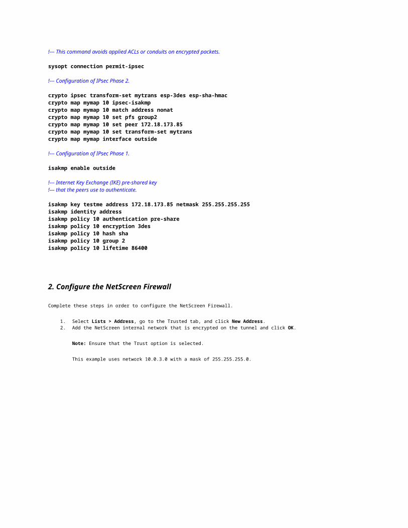
1. Select Lists > Address, go to the Untrusted tab, and click New Address.2. Add the remote network that NetScreen Firewall uses when it encrypts packets and click OK.
Note: Do not use address groups when you configure a VPN to a non NetScreen gateway. VPN interoperability fails if you use address groups. The non NetScreen security gateway does not know how to interpret the proxy ID created by NetScreen when address group is used.
There are couple of workarounds for this:
o Separate the address groups into individual address book entries. Specify individual policies on a per address book entry basis.
o Configure proxy ID to be 0.0.0.0/0 on the non NetScreen gateway (firewall device) if possible.
This example uses network 10.0.25.0 with a mask of 255.255.255.0.
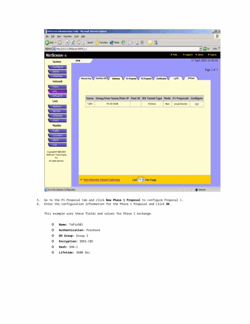
3. Select Network > VPN, go to the Gateway tab, and click New Remote Tunnel Gateway to configure the VPN gateway (Phase 1 and Phase 2 IPsec policies).
4. Use the IP address of the PIX's outside interface in order to terminate the tunnel, and configure the Phase 1 IKE options to bind. Click OK when you are finished.
This example uses these fields and values.
o Gateway Name: To501
o Static IP Address: 172.18.124.96
o Mode: Main (ID Protection)
o Preshared Key: "testme"
o Phase 1 proposal: pre-g2-3des-sha
When the remote tunnel gateway is successfully created, a screen similar to this appears.

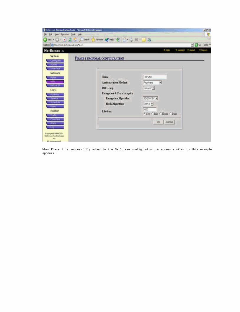
5. Go to the P1 Proposal tab and click New Phase 1 Proposal to configure Proposal 1.6. Enter the configuration information for the Phase 1 Proposal and click OK.
This example uses these fields and values for Phase 1 exchange.
o Name: ToPix501
o Authentication: Preshare
o DH Group: Group 2
o Encryption: 3DES-CBC
o Hash: SHA-1
o Lifetime: 3600 Sec.
When Phase 1 is successfully added to the NetScreen configuration, a screen similar to this example appears.
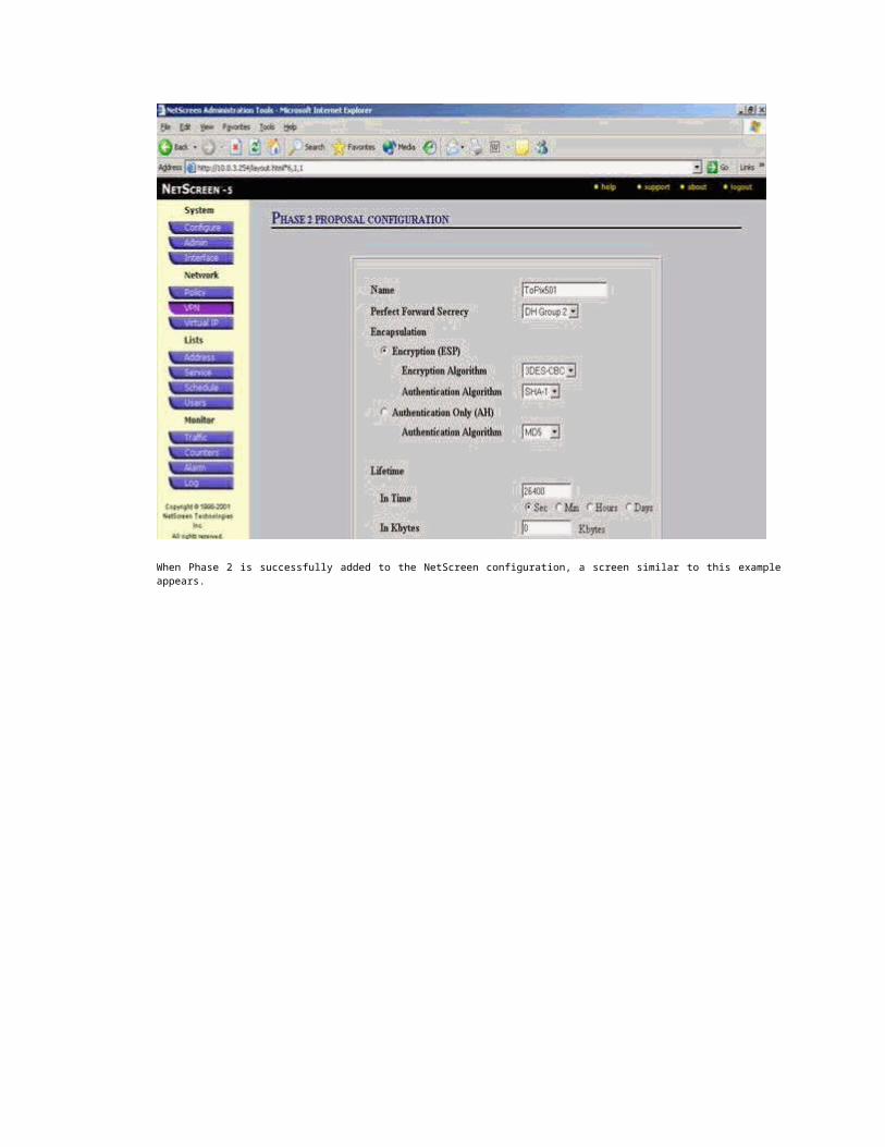
7. Go to the P2 Proposal tab and click New Phase 2 Proposal to configure Phase 2.8. Enter the configuration information for the Phase 2 Proposal and click OK.
This example uses these fields and values for Phase 2 exchange.
o Name: ToPix501
o Perfect Forward Secrecy: DH-2 (1024 bits)
o Encryption Algorithm: 3DES-CBC
o Authentication Algorithm: SHA-1
o Lifetime: 26400 Sec

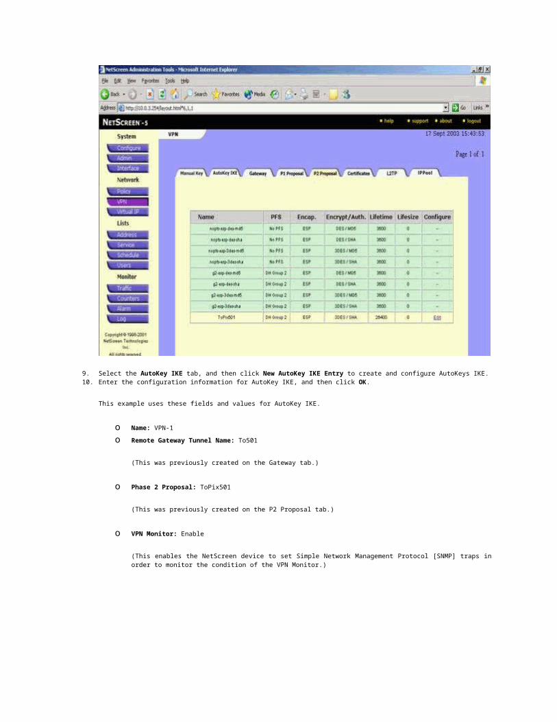
When Phase 2 is successfully added to the NetScreen configuration, a screen similar to this example appears.
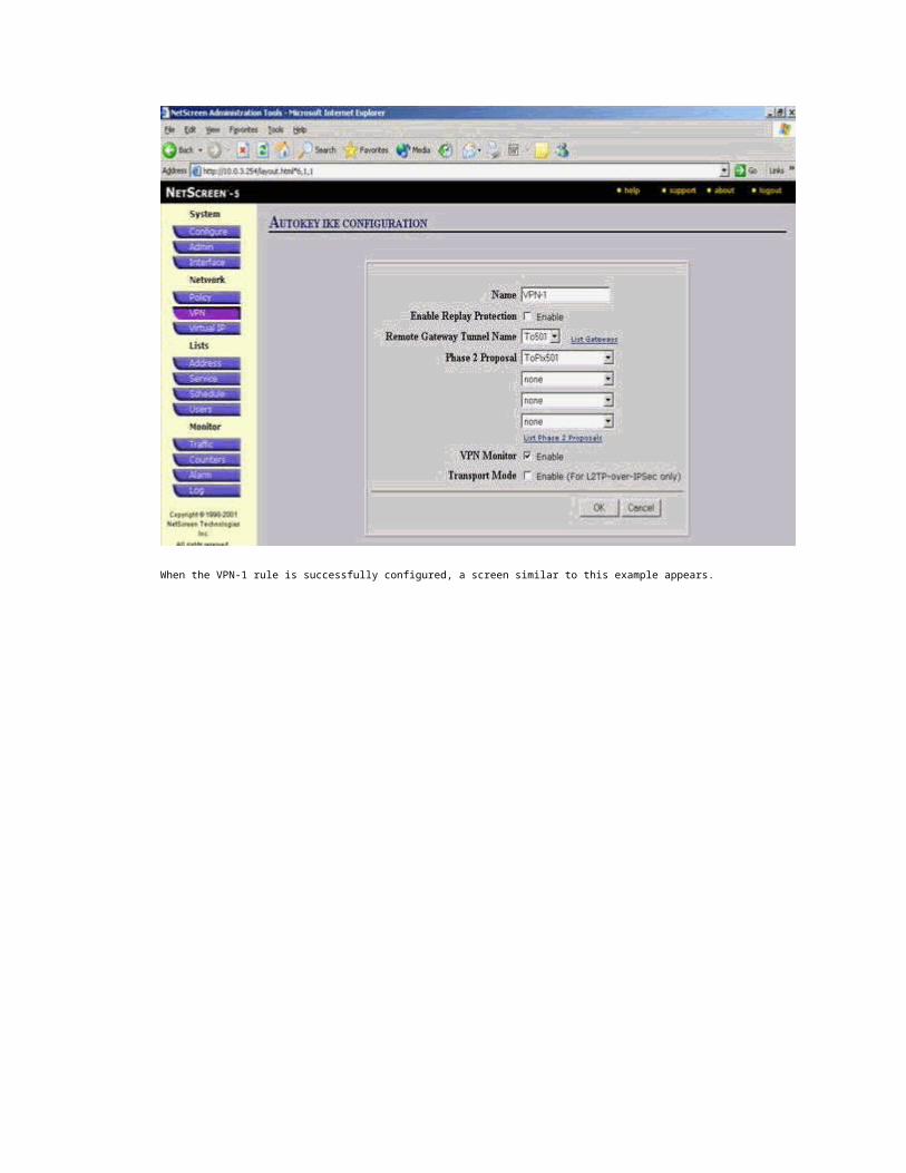
9. Select the AutoKey IKE tab, and then click New AutoKey IKE Entry to create and configure AutoKeys IKE.10. Enter the configuration information for AutoKey IKE, and then click OK.
This example uses these fields and values for AutoKey IKE.
o Name: VPN-1
o Remote Gateway Tunnel Name: To501
(This was previously created on the Gateway tab.)
o Phase 2 Proposal: ToPix501
(This was previously created on the P2 Proposal tab.)
o VPN Monitor: Enable
(This enables the NetScreen device to set Simple Network Management Protocol [SNMP] traps in order to monitor the condition of the VPN Monitor.)
When the VPN-1 rule is successfully configured, a screen similar to this example appears.
11. Select Network > Policy, go to the Outgoing tab, and click New Policy to configure the rules that allow encryption of the IPsec traffic.12. Enter the configuration information for the policy and click OK.
This example uses these fields and values for the policy. The Name field is optional and is not used in this example.
o Source Address: InsideNetwork
(This was previously defined on the Trusted tab.)
o Destination Address: RemoteNetwork
(This was previously defined under the Untrusted tab.)
o Service: Any
o Action: Tunnel
o VPN Tunnel: VPN-1
(This was previously defined as the VPN tunnel on the AutoKey IKE tab.)
o Modify matching incoming VPN policy: Checked
(This option automatically creates an inbound rule that matches the outside network VPN traffic.)

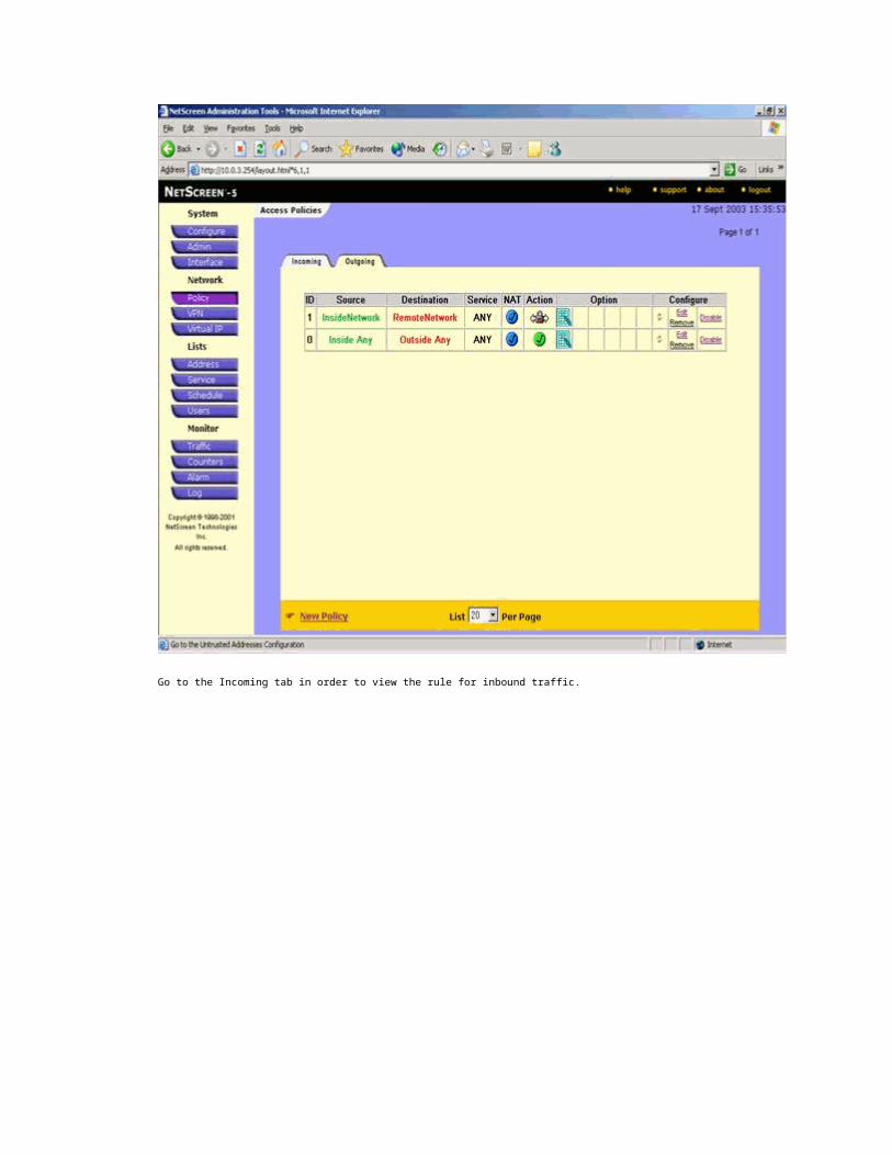
13. When the policy is added, ensure that the outbound VPN rule is first in the list of policies. (The rule that is created automatically for inbound traffic is on the Incoming tab.)
Complete these steps if you need to change the order of the policies:
a. Click the Outgoing tab.
b. Click the circular arrows in the Configure column in order to display the Move Policy Micro window.
c. Change the order of the policies so that the VPN policy is above policy ID 0 (so that the VPN policy is at the top of the list).

Go to the Incoming tab in order to view the rule for inbound traffic.
Related Documents