Configuration of a S7 Connection via Industrial Ethernet with SIMATIC NET V6.1 (SOFTNET-S7) Whitepaper The information in this article refers to: - SIMATIC NET Software-Product-CD 11/2002 (Software-Version V6.1). - CitectSCADA V5.x Summary: This article describes the configuration of a S7 Connection with the SIMATIC NET software V6.1. Communication is acheived using a standard network card (e.g. 3COM) via Softnet-S7 Industrial Ethernet to a S7-300 with an Ethernet CP343 module. There is no STEP7 installed on the PC.

Welcome message from author
This document is posted to help you gain knowledge. Please leave a comment to let me know what you think about it! Share it to your friends and learn new things together.
Transcript

Configuration of a S7 Connection via Industrial Ethernet with SIMATIC NET V6.1 (SOFTNET-S7)
Whitepaper The information in this article refers to: - SIMATIC NET Software-Product-CD 11/2002 (Software-Version V6.1). - CitectSCADA V5.x Summary: This article describes the configuration of a S7 Connection with the SIMATIC NET software V6.1. Communication is acheived using a standard network card (e.g. 3COM) via Softnet-S7 Industrial Ethernet to a S7-300 with an Ethernet CP343 module. There is no STEP7 installed on the PC.

1. General information
Citect performs communication via the S7-Functions (S7API) of Siemens. Therefore the Siemens software (SIMATIC NET) with the S7-Functions must be installed and configured before successful communications with the Citect S7NT driver is possible.
Fig. 1: Communication principle
The SIMATIC NET software supports different kinds of communication (MPI, Profibus, Ethernet) with Siemens PLCs. Therefore it is possible to use one Citect driver for different kinds of communication (MPI, Profibus, Ethernet) since the S7API makes it transparent.
The following operating systems are supported by the Citect S7 driver:
S7NT S7WIN S7NTSP S7WINSP
Windows 2000/XP Windows 95/98E Windows 2000/XP Windows 95/98
S7NTSP and S7WINSP driver support reading from PID Blocks. ATTENTION The S7NTSP and S7WINSP drivers do not perform Blocking. Therefore it has lower performance than the S7NT/S7WIN drivers. The latest Citect drivers can be downloaded from www.citect.com.
The following SIMATIC NET versions are supported by Citect:
SIMATIC Net V6.1 SIMATIC Net V6.0
Windows XP Professional + SP1 Windows NT4.0+SP6.0a or Windows 2000 Professional+SP1/2/3
ATTENTION SIMATIC NET V6.0 does not support Windows 2000 service pack 4. SIMATIC NET version 6.0 requies service pack 4 or higher (of Simatic NET).
Citect / SIMATIC NET V6.1 – Whitepaper V1.0 ( 2 / 29 )

2. Configuration example
Required Software / Hardware Software - Siemens SIMATIC NET Software V6.1 SOFTNET-S7 Industrial Ethernet - CitectSCADA V5.x - Windows XP + SP1
Hardware - Standard Network Card - S7-300 with CPU315-2 DP - Siemens power supply PS30 / 5A - Siemens CP343-1 TCP
Fig. 2: Configuration Example
The hardware modules occupy the following slots in the Siemens PLC: 1. Siemens Power Supply 2. S7-300 CPU 315-2 DP 3. Ethernet CP343-1 TCP
Information: The card location of S7 CPU becomes important later in the configuration.
Citect / SIMATIC NET V6.1 – Whitepaper V1.0 ( 3 / 29 )

3. Installation of SIMATIC NET Software V6.1
1. Once you have logged on to the PC with administration rights, put the SIMATIC NET CD in the CD drive. Should the installation not start automatically, then you can run Setup.exe from the root directory of the CD.
2. Start the SIMATIC NET installation by clicking on the button Install SIMATIC NET Software.
Fig. 1: SIMATIC NET Software installation
3. Read the information below, it is important to familiarise yourself with the new properties of the changed configuration; to continue click Next >.
Fig. 2: Information about Changed Configuration
Citect / SIMATIC NET V6.1 – Whitepaper V1.0 ( 4 / 29 )

4. In the Setup Language dialogue select the langauge applicable to you. In this case English; to continue click Next >.
Fig. 3: Selection of the Setup Language
5. End all currently running Windows programs; to continue Click Next >.
Fig. 4: SIMATIC NET Installations start
Information: Also disable your virus scanner temporarily for the installation!!
Citect / SIMATIC NET V6.1 – Whitepaper V1.0 ( 5 / 29 )

6. Read the software licence contract and click Yes if you agree to the license agreement.
Fig. 5: Software Licence agreement
Information:
The software can be used for testing and validation purposes without a license.
7. Enter your name and company in the dialogue user registration; to continue click Next >.
Fig. 8: User Registration
Citect / SIMATIC NET V6.1 – Whitepaper V1.0 ( 6 / 29 )

If you already have SIMATIC NET software installed, this drive should then be selected as the destination drive. Untick the option to Run automatic authorization; to continue Click Next >.
Fig. 9: Destination drive selection
Infomation: Authorizing the software can be done at a later time. Usually this authorization key is located on a separate floppy disk.
8. Select all application options to be installed. This is necessary if no STEP7 is installed on your PC. If STEP7 V5.2 or higher is already on your PC, it is not necessary to install SIMATIC NCM PC/S7 V5.2; to continue Click Next >.
Fig. 10: Installing applications
Citect / SIMATIC NET V6.1 – Whitepaper V1.0 ( 7 / 29 )

9. The SIMATIC NET Setup will now install some components. It will then request that the system be restarted in order to complete the installation; to confirm click OK.
Fig. 11: Restart of the system
10. After the restart of the system the installation of the Setup is locked. The installation may take several minutes to complete. Once setup is successful, Click Finish to restart the computer.
Fig. 12: Installation was successful.
11. The installation of the SIMATIC NET software is finished!!
Citect / SIMATIC NET V6.1 – Whitepaper V1.0 ( 8 / 29 )

4. Configuration of the SIMATIC NET software
After the successful installation of SIMATIC NET software a computer restart is automatically done. On startup a search of the hardware configuration of the PC system is performed.
Fig. 13: Searching hardware configuration of the PC system Information: When the hardware configuration of the PC is changed later on, for example if an extra CP card is added, or a component is inadvertently deleted via the Compenent Configurator, then you need to set the mode of that card via the ‚Configuration Console’ from ‚not yet specified’ to ‚PG-Operation’ to be able to set the parameters for that card. Citect needs the card to be set in ‚configured mode’. This can be quite tricky since this phenomenon also happens when you remove a broken card and replace it. Then on startup the card is automatically put in ‚not yet specified’ mode, and thus the Citect S7NT driver will not go online, although in Citect nothing was changed !! For more info see th chapter 5, Troubleshooting.
Step 1: Defining the module configuration
1. Once you have successfully installed the hardware and software and have restarted the computer, the commissioning wizard opens as the first step; to continue Click Next >.
Fig. 14: SIMATIC NET Commissioning Wizard after restarting computer for the first time
The number of steps required depends on the number of PC Ethernet Cards (or modules) detected in your PC. The more modules you operate in the computer, the more steps are run through. Information: The Commissioning Wizard is also found under Start/Simatic/SIMATIC NET/Settings/Commissioning Wizard.
Citect / SIMATIC NET V6.1 – Whitepaper V1.0 ( 9 / 29 )

2. Select Use the module for productive operation in configured PC station; to continue Click Next >.
Fig. 15: SIMATIC NET Commissioning Wizard - defining the module mode
An Ethernet Network Card with with the IP addresses settings shown above was found. This is the Network Card which will be configured for communication with the Siemens PLC. This is put on index 5. Information: The index of the Network card can be set with the NCM PC Configuration (hardware configuration). The station Index defaults to 5 if you use the Commissioning Wizard.
3. Deactivate the SIMATIC NET OPC Server in configured PC Station and select Configure more applications; to continue click Next >.
Fig. 16: SIMATIC NET Commissioning Wizard Settings for the local software application
Citect / SIMATIC NET V6.1 – Whitepaper V1.0 ( 10 / 29 )

4. Register the names for your user application. In this case VFD1. This user application is then put on index 1; to continue Click Next >.
Fig. 17: SIMATIC NET Commissioning Wizard - Application fixed on index 1
Information: The name of the application is the VFD name. This comes later in the Citect Project Editor under Communication | Ports, in the field Special options.
7. The module configuration is finished; to continue Click Next >.
Fig. 18: Module configuration is finished
Citect / SIMATIC NET V6.1 – Whitepaper V1.0 ( 11 / 29 )

8. The configuration is stored and the PC station is reconfigured. Existing configuration data will be lost; to confirm Click OK.
Fig. 19: Saving the configuration
9. The Module configuration is finished!! Step 2: Project configuration with the PC Station Wizard
Citect / SIMATIC NET V6.1 – Whitepaper V1.0 ( 12 / 29 )
1. Start the PC Station Wizard…
Fig. 20: PC Station Wizard

Choose Create a new project and configuration. A new project is created; to continue Click Next >.
Fig. 21: Create a new project and configuration
2. Define a project name, in this example CitectS7 is used. Also specify where the copy of the
local PC station settings will reside; to continue Click Next >.
Fig. 22: Enter Project name
Citect / SIMATIC NET V6.1 – Whitepaper V1.0 ( 13 / 29 )
3. Choose the option Edit network and connection configuration; to confirm Click Finish. This will automatically launch NetPro.
Fig. 23: Edit network and connection configuration
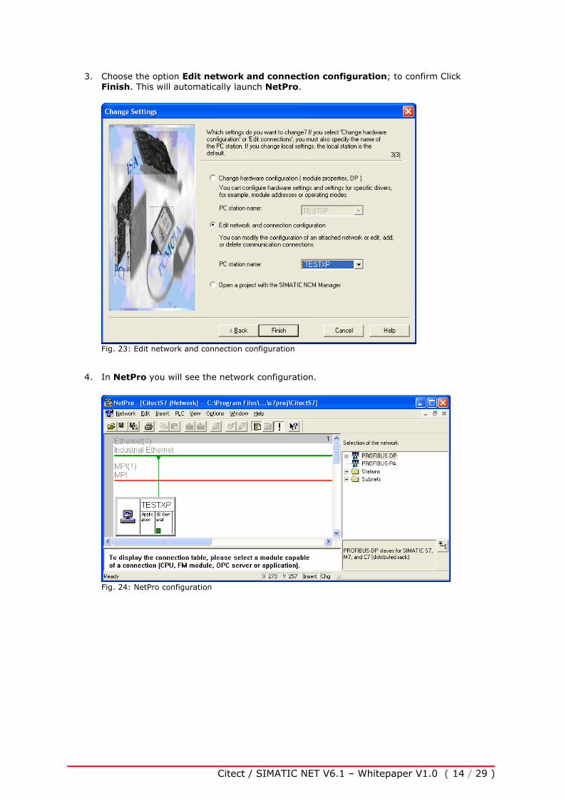
4. In NetPro you will see the network configuration.
Fig. 24: NetPro configuration
Citect / SIMATIC NET V6.1 – Whitepaper V1.0 ( 14 / 29 )

5. Click on the Application box in the PC Station, and from the menu select Insert / New Connection…
Fig. 25: Insert new connection
6. Im the dialog Insert New Connection choose Unspecified, then as Connection Type a
S7-Connection; to confirm Click OK or Apply.
Citect / SIMATIC NET V6.1 – Whitepaper V1.0 ( 15 / 29 )
Fig. 26: New S7-Connection

7. In the Properties – S7-Connection dailog window, the local IP Address should be the
address of the Ethernet card in the PC. In our case 192.168.0.190. The partner IP Address should be that of the Ethernet CP343 module in the PLC, in this case 192.168.0.148. The Local ID is the connection identifier of this connection. In this case S7-Connection_1. It will be used later on as the address of the Citect I/O Device. Afterwards click on the box Address Details… .
Fig. 27: Enter the PLC’s IP Address and Local ID.
Information: The Local ID “S7-Connection_1” is used later in the Citect Project Editor under Communication | I/O Devices in the I/O Device Address field. Take care of spelling!! (Case Sensitive). This name may also not contain any spaces.
8. In the dialog Address Details enter the card location of the CPU the SIMATIC S7 communicates with. In our case the card location is 2; to confirm Click OK.
Fig. 28: Enter Card location of the CPU
Information: Note that some power supplies may occupy 2 slots. The card location of the CPU is then one higher at 3.
Citect / SIMATIC NET V6.1 – Whitepaper V1.0 ( 16 / 29 )

9. In the window NetPro you will notice the new “S7-Connection_1”. Now select Network / Save and Compile …
Fig. 29:Placing one S7-Connection in NetPro.
10. In the dialog Save and Compile select Compile and check everything; to confirm Click
OK.
Fig. 30: Save and Compile
11. After completing the save and compile operation a message appears in the NetPro window. This indicates the warnings and errors present in the configuration. If warnings should occur here, then this is to be handled as information only. In the case of errors however it is not possible to load the project configuration. To view errors at any time, go to the menu View / Outputs.
Fig. 31: NetPro – Save and Compile without errors
Citect / SIMATIC NET V6.1 – Whitepaper V1.0 ( 17 / 29 )

12. Highlight by clicking on the PC Station (TESTXP). Afterwards the connection table disappears in the message window. From the NetPro menu go PLC / Download / Selected Stations to transfer the project configuration to the PC. Alternatively you can right click on the PC Station and select Download / Selected Stations.
Fig. 32: NetPro – Load Configuration into the target system
13. To confirm the overwrite of configuration data and to proceed with the download, click Yes.
Fig. 33: Load target system
14. To confirm stopping the Target Module (Network interface Card) click OK.
Fig. 34: Stop Target Module
15. The configuration should now be successfully loaded. Exit NetPro and click Next, and
Next again to finish the Commissioning Wizard. If an error should arise, then you should consult chapter 5 Troubleshooting for more information.
Citect / SIMATIC NET V6.1 – Whitepaper V1.0 ( 18 / 29 )

Step 3: Defining a unique Access Point for the application 1. The Configuration Console should appear after terminating the Commissioning Wizard. If it
doesn’t, you can open the “Configuration Console” by selecting START / SIMATIC / Simatic Net / Settings / Configuration Console.
2. In the dialog “Configuration Console” highlight the Access Point object with a right mouse click, and select New | New access point.
Fig. 35: Configuration Console – New access point
Information: The name of the Access point is free to choose. It should not contain spaces and should not be greater than 32 characters in length.
3. In the dialog New access point enter your access point name. In our case CitectS7. Select the hardware component that will be associated with this access point. In our case TCP/IP -> ASUSTeK/Broadcom 440x… .
Fig. 36: New Citect access point Information: The name of the access point is used later in CitectSCADA in the Project Editor under Communication | Boards in the Special Options field. Take care of your spelling!! (Case Sensitive)
Citect / SIMATIC NET V6.1 – Whitepaper V1.0 ( 19 / 29 )

4. After creating the access point the Configuration Console should look as follows.
Fig. 37: PC Station – Creation of new access point
5. You can now close the Configuration Console. The Simatic NET software configuration is now complete!!!!
Citect / SIMATIC NET V6.1 – Whitepaper V1.0 ( 20 / 29 )

5. CitectSCADA S7-Driver Configuration
The Citect S7 driver needs three names (settings) from the SIMATIC NET software configuration. The following points are needed:
SIMATIC NET Configuration example Citect Info
Access point of the application CitectS7 Boards, Special options Field
Chapter 4,Step 3 Point 3
VFD/Application Name VFD1 Ports, Special options Field
Chapter 4,Step 1 Point 4
Name of the connection (or Local ID)
S7-Connection_1 IODevices, Address Field
Chapter 4,Step 1 Point 7
Step 1: CitectSCADA Express Wizard (Communication)
1. In Citect Explorer create a NEW (empty) test project.
2. Then go to Citect Project Editor under the Communication menu select Express Wizard.
Do the following in the wizard:
1. Create a new I/O Servers e.g. IOServer
2. Create a new I/O Device e.g. IODev
3. Select external as the type of the I/O Device (PLC) Select the Siemens | S7-300 or S7-400| TCPIP using NE2000 network CARD for Windows NT for NT/W2K/XP/2003 or TCPIP using NE2000 network CARD for Windows 95/98 for 95/98/ME.
Citect / SIMATIC NET V6.1 – Whitepaper V1.0 ( 21 / 29 )
Fig. 38: Selection of the Citect driver

4. Define the name of the connection. We defined this (Local ID) name previously in chapter 4 Configuration of SIMATIC NET Software Step 1, Point 7. In this example it is S7-Connection_1.
Fig. 39: Enter "Connection name"
Information: Take care of your spelling!!! (Case sensitive)
4. Do not Link I/O Device to an external tag Database.
5. Finished !!
Step 2: Setting the Access Point of the application in Citect
1. Open the Boards Form. You will find this in the Citect Project Editor under Communication | Boards.
2. Enter in the Special Options field, the Access Point of the application. In this particular case the name CitectS7 is used. The name CitectS7 was defined in chapter 4 Configuration of SIMATIC NET Software under Step 3, Point 3.
Fig. 40: Enter the "Access Point of the application"
Citect / SIMATIC NET V6.1 – Whitepaper V1.0 ( 22 / 29 )

Step 3: Setting the VFD Name in Citect
1. Open the Ports Form. You will find this in the Citect Project Editor under Communication | Ports.
2. Enter in the Special Options the VFD Name. In this case VFD1. We have defined this name before in the chapter 4 Configuration of SIMATIC NET Software under Step 1, Point 4.
Fig. 41: Enter VFD Name
Step 4: Check the Name of the S7 Connection
1. Open the I/O Device Form. You will find this in the Citect Project Editor under Communication | I/O Devices.
2. Enter in the Address field the "name of the connection" to the PLC. We have defined this before in chapter 4 Configuration of SIMATIC NET Software under Step 1, Point 7. In our case it is S7-Connection_1.
Fig. 42: Check the name of the connection
Citect / SIMATIC NET V6.1 – Whitepaper V1.0 ( 23 / 29 )

Step 5: CitectSCADA S7 Variable declaration
1. Open the Tags Form. You will find this in the Citect Project Editor under Tags | Variable Tags.
2. Create a variable with the following information:
Variable Tag Name: TestInteger I/O Device Name: IODev Type: INT Address: DB190,0
Fig. 43: Creation of a Citect Variable
Information: For more information about the different data types and the Citect variable addressing format, look in the description of the driver (Citect Help).
Citect / SIMATIC NET V6.1 – Whitepaper V1.0 ( 24 / 29 )

6. Troubleshooting
1. Question: I receive the following error message when performing a Download of the PC station in the SIMATIC NCM PC manager. Details: "the module “station manager“ cannot be contacted. Change the on-line interface."
"For On-line connections via the PC internal interface a station name must be assigned in the component configurator. This name must be identical to the name of the PC station, as configured in the STEP7 (or Simatic Net) project."
"Online: No connection could be made. The participant does not announce itself."
Solution:
1. Check in SIMATIC NCM PC Manager (or "SIMATIC manager" in STEP 7) under the Menu option Options | Set PG/PC Interface, whether the point of entrance S7ONLINE is linked with the PC internal (local) interface.
Fig. 44: Set PG/PC Interface
2. The Station Confugration Editor tells you whether your module is Online. You can start the Station Configuration Editor by double clicking on the icon.
Station Configuration Editor
Citect / SIMATIC NET V6.1 – Whitepaper V1.0 ( 25 / 29 )

This should not be OFFLINE, so to change its mode of operation, click on the button Change Mode… The mode of operation should now change to ONLINE.
Fig. 45: Station Configuration Editor: OFFLINE
3. Check the station name in the Station Configuration Editor.
This must match with the name in SIMATIC NCM PC Manager. You can change the station name in the Station Configuration Editor by clicking Station Name…
Citect / SIMATIC NET V6.1 – Whitepaper V1.0 ( 26 / 29 )
Fig. 46: Checking Station name

4. Open the Station Configuration Editor and the SIMATIC NCM PC Manager (or in Step7 the PC-Station). Check the order and the number of configured components and the indexes that are used. These should match.
Fig. 47: Checking the group configuration
Citect / SIMATIC NET V6.1 – Whitepaper V1.0 ( 27 / 29 )

5. FAQs
Question How can I reread the hardware configuration, if the module is not detected in the Station Configurator? Solution Modify the PC Station settings in the Configuration Console. You can find this in Start / SIMATIC / SIMATIC NET / Settings / Configuration Console. Change the Mode of the module to “not yet specified”.
Fig. 48: PC-Station settings – Changing mode (Ethernet module)
After setting this, you should start the Commissioning Wizard. This can be found in Start / SIMATIC NET / Settings / Commissioning Wizard. The required steps are described in chapter 4 Configuration of SIMATIC NET Software. Information: Configured Mode In this mode, all parameters of the module are specified in the defined configuration of the automation project and transferred to the module. If you use this mode, you can use all the protocols available with SIMATIC NET as well as the OPC Server with the module. PG-Operation In this mode, the network-related parameters of the module such as the station address and transmission rate are set using the "Set PG/PC Interface" configuration tool. This configuration is possible only locally on the computer itself. If you select this mode, PG functions (for example, SIMATIC STEP 7) can be used with the module. Communication functions requiring a configuration as defined in a project or OPC operation are then not possible. Not yet specified If you select this setting, the mode is indicated as "not yet specified". This is the original setting after you have installed the module. The next time you start the Commissioning Wizard, the module will be treated like a newly detected module and the module can be initialized again.
Citect / SIMATIC NET V6.1 – Whitepaper V1.0 ( 28 / 29 )

6. Contact Information
SIEMENS Australia Cnr Herring and Talavera Road Macquarie Park, North Ryde 2113 Australia Tel 13 72 22 Fax 1300 360 222 Siemens Automation Technical Support Telephone: 1800 630 685 Web: http://www.siemens.com.au Citect Pty Ltd 3 Fitzsimons Lane Gordon NSW 2072 Australia Telephone: +61 (0) 2 9496 6000 Fax: +61 (0) 2 9496 7399 E-Mail: [email protected] Web: http://www.citect.com/
Citect / SIMATIC NET V6.1 – Whitepaper V1.0 ( 29 / 29 )
Related Documents