Huawei AR2200-S Series Enterprise Routers V200R001C01 Configuration Guide - VPN Issue 01 Date 2012-01-06 HUAWEI TECHNOLOGIES CO., LTD.

Welcome message from author
This document is posted to help you gain knowledge. Please leave a comment to let me know what you think about it! Share it to your friends and learn new things together.
Transcript

Huawei AR2200-S Series Enterprise RoutersV200R001C01
Configuration Guide - VPN
Issue 01
Date 2012-01-06
HUAWEI TECHNOLOGIES CO., LTD.

Copyright © Huawei Technologies Co., Ltd. 2012. All rights reserved.No part of this document may be reproduced or transmitted in any form or by any means without prior writtenconsent of Huawei Technologies Co., Ltd. Trademarks and Permissions
and other Huawei trademarks are trademarks of Huawei Technologies Co., Ltd.All other trademarks and trade names mentioned in this document are the property of their respective holders. NoticeThe purchased products, services and features are stipulated by the contract made between Huawei and thecustomer. All or part of the products, services and features described in this document may not be within thepurchase scope or the usage scope. Unless otherwise specified in the contract, all statements, information,and recommendations in this document are provided "AS IS" without warranties, guarantees or representationsof any kind, either express or implied.
The information in this document is subject to change without notice. Every effort has been made in thepreparation of this document to ensure accuracy of the contents, but all statements, information, andrecommendations in this document do not constitute the warranty of any kind, express or implied.
Huawei Technologies Co., Ltd.Address: Huawei Industrial Base
Bantian, LonggangShenzhen 518129People's Republic of China
Website: http://www.huawei.com
Email: [email protected]
Issue 01 (2012-01-06) Huawei Proprietary and ConfidentialCopyright © Huawei Technologies Co., Ltd.
i

About This Document
Intended AudienceThis document provides the basic concepts, configuration procedures, and configurationexamples in different application scenarios of the VPN supported by the AR2200-S device.
This document describes how to configure the VPN.
This document is intended for:
l Data configuration engineers
l Commissioning engineers
l Network monitoring engineers
l System maintenance engineers
Symbol ConventionsThe symbols that may be found in this document are defined as follows.
Symbol Description
DANGERIndicates a hazard with a high level of risk, which if notavoided, will result in death or serious injury.
WARNINGIndicates a hazard with a medium or low level of risk, whichif not avoided, could result in minor or moderate injury.
CAUTIONIndicates a potentially hazardous situation, which if notavoided, could result in equipment damage, data loss,performance degradation, or unexpected results.
TIP Indicates a tip that may help you solve a problem or savetime.
NOTE Provides additional information to emphasize or supplementimportant points of the main text.
Huawei AR2200-S Series Enterprise RoutersConfiguration Guide - VPN About This Document
Issue 01 (2012-01-06) Huawei Proprietary and ConfidentialCopyright © Huawei Technologies Co., Ltd.
ii

Command ConventionsThe command conventions that may be found in this document are defined as follows.
Convention Description
Boldface The keywords of a command line are in boldface.
Italic Command arguments are in italics.
[ ] Items (keywords or arguments) in brackets [ ] are optional.
{ x | y | ... } Optional items are grouped in braces and separated by verticalbars. One item is selected.
[ x | y | ... ] Optional items are grouped in brackets and separated by verticalbars. One item is selected or no item is selected.
{ x | y | ... }* Optional items are grouped in braces and separated by verticalbars. A minimum of one item or a maximum of all items can beselected.
[ x | y | ... ]* Optional items are grouped in brackets and separated by verticalbars. Several items or no item can be selected.
&<1-n> The parameter before the & sign can be repeated 1 to n times.
# A line starting with the # sign is comments.
Interface Numbering ConventionsInterface numbers used in this manual are examples. In device configuration, use the existinginterface numbers on devices.
Change HistoryChanges between document issues are cumulative. Therefore, the latest document versioncontains all updates made to previous versions.
Changes in Issue 01 (2012-01-06)Initial commercial release.
Huawei AR2200-S Series Enterprise RoutersConfiguration Guide - VPN About This Document
Issue 01 (2012-01-06) Huawei Proprietary and ConfidentialCopyright © Huawei Technologies Co., Ltd.
iii

Contents
About This Document.....................................................................................................................ii
1 GRE Configuration.......................................................................................................................11.1 Introduction to GRE...........................................................................................................................................21.2 GRE Features Supported by the AR2200-S.......................................................................................................21.3 Configuring GRE................................................................................................................................................3
1.3.1 Establishing the Configuration Task.........................................................................................................31.3.2 Configuring a Tunnel Interface.................................................................................................................41.3.3 Configuring Routes for the Tunnel............................................................................................................51.3.4 (Optional) Configuring GRE Security Options.........................................................................................61.3.5 Checking the Configuration.......................................................................................................................7
1.4 Configuring the Keepalive Function..................................................................................................................81.4.1 Establishing the Configuration Task.........................................................................................................81.4.2 Enabling the Keepalive Function..............................................................................................................91.4.3 Checking the Configuration.....................................................................................................................10
1.5 Maintaining GRE..............................................................................................................................................111.5.1 Resetting the Statistics of a Tunnel Interface..........................................................................................111.5.2 Monitoring the Running Status of GRE..................................................................................................121.5.3 Debugging GRE......................................................................................................................................12
1.6 Configuration Examples...................................................................................................................................121.6.1 Example for Configuring a Static Route for GRE...................................................................................121.6.2 Example for Configuring a Dynamic Routing Protocol for GRE...........................................................171.6.3 Example for Configuring a GRE Tunnel to Transmit VPN Multicast Data Encrypted with IPSec........201.6.4 Example for Configuring the Keepalive Function for GRE....................................................................26
2 MCE Configuration.....................................................................................................................292.1 Introduction to MCE.........................................................................................................................................30
2.1.1 MCE Overview........................................................................................................................................302.1.2 MCE Functions Supported by the AR2200-S.........................................................................................31
2.2 Configuring a VPN Instance.............................................................................................................................312.2.1 Establishing the Configuration Task.......................................................................................................322.2.2 Creating a VPN instance..........................................................................................................................322.2.3 Binding an Interface with a VPN Instance..............................................................................................332.2.4 Checking the Configuration.....................................................................................................................34
Huawei AR2200-S Series Enterprise RoutersConfiguration Guide - VPN Contents
Issue 01 (2012-01-06) Huawei Proprietary and ConfidentialCopyright © Huawei Technologies Co., Ltd.
iv

2.3 Configuring a Route Multi-Instance Between an MCE and a Site...................................................................342.3.1 Establishing the Configuration Task.......................................................................................................342.3.2 (Optional) Configuring a Static Route Between an MCE and a Site......................................................352.3.3 (Optional) Configuring RIP Between an MCE and a Site.......................................................................362.3.4 (Optional) Configuring OSPF Between an MCE and a Site...................................................................362.3.5 (Optional) Configuring IS-IS Between an MCE and a Site....................................................................372.3.6 Checking the Configuration.....................................................................................................................37
2.4 Configuring a Route Multi-Instance Between an MCE and a PE....................................................................382.4.1 Establishing the Configuration Task.......................................................................................................382.4.2 (Optional) Configuring a Static Route Between an MCE and a PE........................................................392.4.3 (Optional) Configuring RIP Between an MCE and a PE........................................................................392.4.4 (Optional) Configuring OSPF Between an MCE and a PE.....................................................................402.4.5 (Optional) Configuring IS-IS Between an MCE and a PE......................................................................412.4.6 Checking the Configuration.....................................................................................................................41
2.5 MCE Configuration Examples.........................................................................................................................422.5.1 Example for Configuring MCE...............................................................................................................42
3 IPSec Configuration....................................................................................................................493.1 IPSec Overview................................................................................................................................................503.2 IPSec Features Supported by the AR2200-S....................................................................................................513.3 Establishing an IPSec Tunnel Manually...........................................................................................................52
3.3.1 Establishing the Configuration Task.......................................................................................................523.3.2 Defining Protected Data Flows................................................................................................................533.3.3 Configuring an IPSec Proposal................................................................................................................533.3.4 Configuring an IPSec Policy...................................................................................................................543.3.5 Applying an IPSec Policy to an Interface................................................................................................563.3.6 Checking the Configuration.....................................................................................................................56
3.4 Establishing an IPSec Tunnel Through IKE Negotiation.................................................................................573.4.1 Establishing the Configuration Task.......................................................................................................573.4.2 Defining Protected Data Flows................................................................................................................583.4.3 Configuring an IKE Proposal..................................................................................................................583.4.4 Configuring an IKE Peer.........................................................................................................................593.4.5 Configuring an IPSec Proposal................................................................................................................613.4.6 Configuring an IPSec Policy...................................................................................................................623.4.7 (Optional) Configuring an IPSec Policy Template..................................................................................633.4.8 (Optional) Setting Optional Parameters..................................................................................................643.4.9 Applying an IPSec policy to an interface................................................................................................653.4.10 Checking the Configuration...................................................................................................................66
3.5 Maintaining IPSec............................................................................................................................................663.5.1 Displaying the IPSec Configuration........................................................................................................663.5.2 Clearing IPSec Information.....................................................................................................................67
3.6 Configuration Examples...................................................................................................................................673.6.1 Example for Establishing an SA Manually.............................................................................................67
Huawei AR2200-S Series Enterprise RoutersConfiguration Guide - VPN Contents
Issue 01 (2012-01-06) Huawei Proprietary and ConfidentialCopyright © Huawei Technologies Co., Ltd.
v

3.6.2 Example for Configuring IKE Negotiation Using Default Settings........................................................723.6.3 Example for Configuring IKE Negotiation.............................................................................................77
Huawei AR2200-S Series Enterprise RoutersConfiguration Guide - VPN Contents
Issue 01 (2012-01-06) Huawei Proprietary and ConfidentialCopyright © Huawei Technologies Co., Ltd.
vi

1 GRE Configuration
About This Chapter
Generic Routing Encapsulation (GRE) encapsulates the packets of certain network layerprotocols so that the encapsulated packets can be transmitted over the IPv4 network.
1.1 Introduction to GREThe transmission of packets in a GRE tunnel involves two processes: encapsulation anddecapsulation. After receiving a packet of a certain network layer protocol that needs to beencapsulated and routed, the system adds a GRE header to the packet, and encapsulates thepacket into a packet of another protocol, such as IP.
1.2 GRE Features Supported by the AR2200-SGRE features supported by the AR2200-S include the following: enlargement of the operationscope of the network running a hop-limited protocol, and working in conjunction with the IPSecurity Protocol (IPSec) to compensate for the IPSec flaw in multicast data protection.
1.3 Configuring GREYou can configure GRE only after a GRE tunnel is configured.
1.4 Configuring the Keepalive FunctionBefore configuring a tunnel policy and a GRE tunnel for the VPN, enable the GRE tunnelKeepalive function. With this function enabled, the VPN does not select the GRE tunnel thatcannot reach the remote end, and data loss can be avoided.
1.5 Maintaining GREThis section describes how to reset the statistics of a tunnel interface and monitor the GRErunning status.
1.6 Configuration ExamplesFamiliarize yourself with the configuration procedures against the networking diagrams. Thissection provides networking requirements, configuration notes, and configuration roadmap inconfigurations examples.
Huawei AR2200-S Series Enterprise RoutersConfiguration Guide - VPN 1 GRE Configuration
Issue 01 (2012-01-06) Huawei Proprietary and ConfidentialCopyright © Huawei Technologies Co., Ltd.
1

1.1 Introduction to GREThe transmission of packets in a GRE tunnel involves two processes: encapsulation anddecapsulation. After receiving a packet of a certain network layer protocol that needs to beencapsulated and routed, the system adds a GRE header to the packet, and encapsulates thepacket into a packet of another protocol, such as IP.
GRE encapsulates the packets of certain network layer protocols. After encapsulation, thesepackets can be transmitted over the network by another network layer protocol, such as IP.
GRE can serve as a Layer 3 tunneling protocol for VPNs. A tunnel is a virtual point-to-pointconnection and can be regarded as a virtual interface that supports only point-to-pointconnections. This interface provides a path to transmit encapsulated datagrams. GREencapsulates and decapsulates datagrams at both ends of the tunnel.
1.2 GRE Features Supported by the AR2200-SGRE features supported by the AR2200-S include the following: enlargement of the operationscope of the network running a hop-limited protocol, and working in conjunction with the IPSecurity Protocol (IPSec) to compensate for the IPSec flaw in multicast data protection.
Enlarging the Operation Scope of the Network Running a Hop-Limited ProtocolIf the hop count between two terminals in Figure 1-1 is more than 15, the two terminals cannotcommunicate with each other.
Figure 1-1 Networking diagram of enlarged network operation scope
IPnetwork
IPnetwork
IPnetwork
PC PC
Tunnel
When the tunnel is used in the network, a few hops are hidden. This enlarges the scope of thenetwork operation.
Working in Combination with IPSec to Compensate for the IPSec Flaw in MulticastData Protection
Based on GRE, multicast data can be encapsulated and transmitted in the GRE tunnel. Based onIPSec, only the unicast data can realize encrypted protection.
Huawei AR2200-S Series Enterprise RoutersConfiguration Guide - VPN 1 GRE Configuration
Issue 01 (2012-01-06) Huawei Proprietary and ConfidentialCopyright © Huawei Technologies Co., Ltd.
2

Figure 1-2 Networking diagram of GRE-IPSec tunnel application
IPSec tunnelGRE tunnel
Internet
Corporateintranet
Remoteoffice
network
As shown in Figure 1-2, if the multicast data is transmitted in the IPSec tunnel, establish theGRE tunnel and encapsulate the multicast data with GRE. Then encrypt the encapsulatedmulticast data with IPSec. When these tasks are performed, the encrypted multicast data can betransmitted in the IPSec tunnel.
1.3 Configuring GREYou can configure GRE only after a GRE tunnel is configured.
1.3.1 Establishing the Configuration TaskBefore configuring a GRE tunnel, familiarize yourself with the applicable environment,complete the pre-configuration tasks, and obtain the data required for the configuration.
Applicable EnvironmentTo set up a GRE tunnel, create a tunnel interface first, and configure the GRE functions on thetunnel interface. If the tunnel interface is deleted, all the configurations on the interface aredeleted.
Pre-configuration TasksBefore configuring an ordinary GRE tunnel, complete the following task:
l Configuring reachable routes between the source and destination interfaces
Data PreparationTo configure an ordinary GRE tunnel, you need the following data.
No. Data
1 Number of the tunnel interface
2 Source address and destination address of the tunnel
Huawei AR2200-S Series Enterprise RoutersConfiguration Guide - VPN 1 GRE Configuration
Issue 01 (2012-01-06) Huawei Proprietary and ConfidentialCopyright © Huawei Technologies Co., Ltd.
3

No. Data
3 IP address of the tunnel interface
4 Key of the tunnel interface
1.3.2 Configuring a Tunnel InterfaceAfter creating a tunnel interface, specify GRE as the encapsulation type, set the tunnel sourceaddress or source interface, and set the tunnel destination address. In addition, set the tunnelinterface network address so that the tunnel can support dynamic routing protocols.
ContextPerform the following steps on the routers at the two ends of a tunnel.
Procedure
Step 1 Run:system-view
The system view is displayed.
Step 2 Run:interface tunnel interface-number
A tunnel interface is created and the tunnel interface view is displayed.
Step 3 Run:tunnel-protocol { gre | none }
The tunnel is encapsulated with GRE.
Step 4 Run:source { source-ip-address | interface-type interface-number }
The source address or source interface of the tunnel is configured.
NOTE
l The virtual IP address of the VRRP backup group can be configured as the source address of the GREtunnel.
l The bridge-if interface can not be configured as the source interface of the GRE tunnel.
The source interface of the tunnel cannot be the interface of the tunnel, but can be specified asthe interface of another tunnel.
Step 5 Run:destination ip-address
The destination address of the tunnel is configured.
Step 6 (Optional) Run:mtu mtu
The Maximum Transmission Unit (MTU) of the tunnel interface is modified.
Huawei AR2200-S Series Enterprise RoutersConfiguration Guide - VPN 1 GRE Configuration
Issue 01 (2012-01-06) Huawei Proprietary and ConfidentialCopyright © Huawei Technologies Co., Ltd.
4

The new MTU takes effect only after you run the shutdown command and the undoshutdown command on the interface.
Step 7 Choose one of the following commands to configure the IP address of the tunnel interface.l Run the ip address ip-address { mask | mask-length } [ sub ] command to configure the IP
address of the tunnel interface.l Run the ip address unnumbered interface interface-type interface-number command to
configure IP unnumbered for the tunnel interface.
To support dynamic routing protocols on a tunnel, configure a network address for the tunnelinterface. The network address of the tunnel interface may not be a public address, but shouldbe in the same network segment on both ends of the tunnel.
By default, the network address of a tunnel interface is not set.
----End
1.3.3 Configuring Routes for the TunnelRoutes for a tunnel must be available on both the source and destination devices so that packetsencapsulated with GRE can be forwarded correctly. A route passing through tunnel interfacescan be a static route or a dynamic route.
ContextPerform the following steps on the devices at two ends of a tunnel.
NOTE
The packets encapsulated with GRE are forwarded correctly only if the routes for the tunnel are availableon both the source and destination routers.
ProcedureStep 1 Run:
system-view
The system view is displayed.
Step 2 Choose one of the following methods to configure routes passing through the tunnel interface.l Run the ip route-static ip-address { mask | mask-length } tunnel interface-number
[ description text ] command to configure a static route.The static route must be configured on both ends of the tunnel. In this command, thedestination address is neither the destination address of the tunnel nor the address of theopposite tunnel interface, but the destination address of the packet that is not encapsulatedwith GRE. The outbound interface must be the local tunnel interface.
l Configure dynamic routes using IGP or BGP. Details for the procedure are not provided here.For the configuration of dynamic routes, see the AR2200-S Configuration Guide - IPRouting.When configuring a dynamic routing protocol, enable the dynamic routing protocol on boththe tunnel interface and the interface connected to the private network. To ensure correctrouting, do not choose the tunnel interface as the next hop when configuring the route to thephysical or logical interface of the destination tunnel.Use Router A in Figure 1-3 as an example. The source interface of Tunnel 0/0/1 is GE 1/0/0on Router A, and its destination interface is GE 2/0/0 on Router C. If a dynamic routing
Huawei AR2200-S Series Enterprise RoutersConfiguration Guide - VPN 1 GRE Configuration
Issue 01 (2012-01-06) Huawei Proprietary and ConfidentialCopyright © Huawei Technologies Co., Ltd.
5

protocol is used, the protocol must be configured on the tunnel interface and the GE interfaceconnected to the PC. Moreover, in the routing table of Router A, the egress with thedestination as the network segment where GE 2/0/0 on Router C resides cannot be Tunnel0/0/1.In practical configurations, configure a multi-process routing protocol or change the metricvalue of the tunnel interface. This prevents the tunnel interface from being selected as theoutbound interface of routes to the destination physical interface of the tunnel.In practical configurations, tunnel interfaces and physical interfaces connected to the publicnetwork should use different routing protocols or different processes of the same routingprotocol. With one of these procedures in place, you can avoid selecting a tunnel interfaceas an outbound interface for packets destined for the destination of the tunnel. In addition, aphysical interface is prevented from forwarding user packets that should be forwardedthrough the tunnel.
Figure 1-3 Diagram of configuring the GRE dynamic routing protocol
RouterA RouterC
Tunnel0/0/1 Tunnel0/0/2
PC2PC1
GE1/0/0 GE2/0/0
Backbone
GE2/0/0 GE1/0/0Tunnel
----End
1.3.4 (Optional) Configuring GRE Security OptionsTo enhance the security of a GRE tunnel, configure end-to-end checksum authentication or keyauthentication. This security mechanism can prevent the tunnel interface from incorrectlyidentifying and receiving packets from other devices.
ContextPerform the following steps on the routers at two ends of a tunnel.
Procedure
Step 1 Run:system-view
The system view is displayed.
Step 2 Run:interface tunnel interface-number
Huawei AR2200-S Series Enterprise RoutersConfiguration Guide - VPN 1 GRE Configuration
Issue 01 (2012-01-06) Huawei Proprietary and ConfidentialCopyright © Huawei Technologies Co., Ltd.
6

The tunnel interface view is displayed.
Step 3 Run:gre checksum
End-to-end checksum authentication is configured for the tunnel.
By default, end-to-end checksum authentication is disabled.
Step 4 Run:gre key key-number
The key is set for the tunnel interface.
If the keys are set for tunnel interfaces on the two ends of the tunnel, ensure that they have thesame key number. Alternatively, you may choose not to set the keys for tunnel interfaces onboth ends of the tunnel.
By default, no key is configured for the tunnel.
NOTEStep 3 and Step 4 can be performed in random order.
----End
1.3.5 Checking the ConfigurationAfter a GRE tunnel is set up, you can view the running status and routing information about thetunnel interface.
ContextThe configurations of the GRE function are complete.
Procedurel Run the display interface tunnel [ interface-number ] command to check tunnel interface
information.l Run the display ip routing-table command to check the IPv4 routing table.l Run the ping -a source-ip-address host command to check whether the two ends of the
tunnel can successfully ping each other.
----End
ExampleRun the display interface tunnel command. If the tunnel interface is Up, the configurationsucceeds. For example:
<Huawei> display interface Tunnel 0/0/1Tunnel0/0/1 current state : UP Line protocol current state : UP Description:HUAWEI, AR Series, Tunnel0/0/1 Interface Route Port,The Maximum Transmit Unit is 1500 Internet Address is 5.5.5.2/24 Encapsulation is TUNNEL, loopback not set Tunnel source 150.1.1.1 (Ethernet4/0/0), destination 150.1.1.2 Tunnel protocol/transport GRE/IP, key disabled keepalive disabled Checksumming of packets disabled
Huawei AR2200-S Series Enterprise RoutersConfiguration Guide - VPN 1 GRE Configuration
Issue 01 (2012-01-06) Huawei Proprietary and ConfidentialCopyright © Huawei Technologies Co., Ltd.
7

Current system time: 2008-03-04 19:17:30 300 seconds input rate 0 bits/sec, 0 packets/sec 300 seconds output rate 0 bits/sec, 0 packets/sec 0 seconds input rate 0 bits/sec, 0 packets/sec 0 seconds output rate 0 bits/sec, 0 packets/sec 0 packets input, 0 bytes 0 input error 0 packets output, 0 bytes 0 output error Input: Unicast: 0 packets, Multicast: 0 packets Output: Unicast: 0 packets, Multicast: 0 packets Input bandwidth utilization : -- Output bandwidth utilization : --
Run the display ip routing-table command. If the route passing through the tunnel interfaceexists in the routing table, the configuration succeeds. For example:
[Huawei] display ip routing-tableRoute Flags: R - relay, D - download to fib------------------------------------------------------------------------------Routing Tables: Public Destinations : 8 Routes : 8Destination/Mask Proto Pre Cost Flags NextHop Interface 10.1.1.0/24 Direct 0 0 D 10.1.1.2 GigabitEthernet2/0/0 10.1.1.2/32 Direct 0 0 D 127.0.0.1 InLoopBack0 10.2.1.0/24 Static 60 0 D 40.1.1.1 Tunnel0/0/2 20.1.1.1/32 Direct 0 0 D 127.0.0.1 InLoopBack0 40.1.1.0/24 Direct 0 0 D 40.1.1.1 Tunnel0/0/2 40.1.1.1/32 Direct 0 0 D 127.0.0.1 InLoopBack0 127.0.0.0/8 Direct 0 0 D 127.0.0.1 InLoopBack0 127.0.0.1/32 Direct 0 0 D 127.0.0.1 InLoopBack0
Run the ping -a source-ip-address host command to see that the ping from the local tunnelinterface to the destination tunnel succeeds.
<Huawei> ping -a 40.1.1.1 40.1.1.2 PING 40.1.1.2: 56 data bytes, press CTRL_C to break Reply from 40.1.1.2: bytes=56 Sequence=1 ttl=255 time=24 ms Reply from 40.1.1.2: bytes=56 Sequence=2 ttl=255 time=33 ms Reply from 40.1.1.2: bytes=56 Sequence=3 ttl=255 time=48 ms Reply from 40.1.1.2: bytes=56 Sequence=4 ttl=255 time=33 ms Reply from 40.1.1.2: bytes=56 Sequence=5 ttl=255 time=36 ms --- 40.1.1.2 ping statistics --- 5 packet(s) transmitted 5 packet(s) received 0.00% packet loss round-trip min/avg/max = 24/34/48 ms
1.4 Configuring the Keepalive FunctionBefore configuring a tunnel policy and a GRE tunnel for the VPN, enable the GRE tunnelKeepalive function. With this function enabled, the VPN does not select the GRE tunnel thatcannot reach the remote end, and data loss can be avoided.
1.4.1 Establishing the Configuration TaskBefore configuring the GRE tunnel Keepalive function, familiarize yourself with the applicableenvironment, complete the pre-configuration tasks, and obtain the required data. This can helpyou complete the configuration task quickly and accurately.
Huawei AR2200-S Series Enterprise RoutersConfiguration Guide - VPN 1 GRE Configuration
Issue 01 (2012-01-06) Huawei Proprietary and ConfidentialCopyright © Huawei Technologies Co., Ltd.
8

Application EnvironmentThe Keepalive function can be configured on one end of a GRE tunnel to test the GRE tunnelstatus. If the remote end is found unreachable, the tunnel is disconnected on time to avoid datablack hole.
Figure 1-4 GRE tunnel supporting Keepalive
RouterA RouterBGRE tunnel
Source DestinationInternet
Pre-configuration TasksBefore configuring the Keepalive function, complete the following tasks:
l Configuring the link layer attributes of the interfacesl Assigning IP addresses to the interfacesl Establishing the GRE tunnel and keeping the tunnel Up
Data PreparationTo configure the Keepalive function, you need the following data.
No. Data
1 Interval for sending Keepalive messages
2 Retry times of the unreachable timer
1.4.2 Enabling the Keepalive FunctionThe GRE tunnel Keepalive function is unidirectional. To implement the Keepalive function onboth ends, enable the Keepalive function on both ends of a GRE tunnel.
ContextPerform the following steps on the router that requires the Keepalive function.
Procedure
Step 1 Run:system-view
The system view is displayed.
Huawei AR2200-S Series Enterprise RoutersConfiguration Guide - VPN 1 GRE Configuration
Issue 01 (2012-01-06) Huawei Proprietary and ConfidentialCopyright © Huawei Technologies Co., Ltd.
9

Step 2 Run:interface tunnel interface-number
The tunnel interface view is displayed.
Step 3 Run:tunnel-protocol gre
The tunnel is encapsulated with GRE.
Step 4 Run:keepalive [ period period [ retry-times retry-times ] ]
The Keepalive function is enabled.
The GRE tunnel Keepalive function is unidirectional. Therefore, to realize the Keepalivefunction on both ends, enable the Keepalive function on both ends of a GRE tunnel. One endcan be configured with the Keepalive function regardless of whether the remote end is enabledwith the Keepalive function. But it is still recommended to enable the Keepalive function onboth ends of the GRE tunnel.
TIP
Before configuring the tunnel policy and the GRE tunnel for the VPN, enable the GRE tunnel Keepalivefunction. With this function enabled, the VPN does not select the GRE tunnel that cannot reach the remoteend, and the data loss can be avoided. The reasons for enabling the Keepalive function are listed below:
l If the Keepalive function is not enabled, the local tunnel interface may always be Up regardless ofwhether data reaches the remote end.
l If the Keepalive function is enabled on the local end, the local tunnel interface is set Down when theremote end is unreachable. As a result, the VPN does not select the unreachable GRE tunnel and thedata is not lost.
----End
1.4.3 Checking the ConfigurationAfter a GRE tunnel is enabled with the Keepalive function, you can view the Keepalive packetsand Keepalive Response packets sent and received by the GRE tunnel interfaces.
PrerequisiteThe Keepalive function is enabled on the GRE tunnel.
Procedure
Step 1 Run:system-view
The system view is displayed.
Step 2 Run:interface tunnel interface-number
The tunnel interface view is displayed.
Step 3 Run:display keepalive packets count
Huawei AR2200-S Series Enterprise RoutersConfiguration Guide - VPN 1 GRE Configuration
Issue 01 (2012-01-06) Huawei Proprietary and ConfidentialCopyright © Huawei Technologies Co., Ltd.
10

Check the Keepalive packets and Keepalive Response packets sent and received by the GREtunnel interface.
----End
ExampleOn the tunnel interface that is enabled with the Keepalive function, run the display keepalivepackets count command to ascertain the number of sent Keepalive packets and receivedKeepalive Response packets on both the local end and the remote end. If the Keepalive functionis successfully configured on the local tunnel interface, the number of sent Keepalive packetsor received Keepalive Response packets on the local end is not 0.
[Huawei] interface tunnel 0/0/1[Huawei-Tunnel0/0/1] tunnel-protocol gre[Huawei-Tunnel0/0/1] keepalive[Huawei-Tunnel0/0/1] display keepalive packets countSend 34 keepalive packets to peers, Receive 34 keepalive response packets from peersReceive 0 keepalive packets from peers, Send 0 keepalive response packets to peers
1.5 Maintaining GREThis section describes how to reset the statistics of a tunnel interface and monitor the GRErunning status.
1.5.1 Resetting the Statistics of a Tunnel InterfaceWhen you need to reset the statistics of a tunnel interface, you can run the reset commands toclear the Keepalive packets and Keepalive Response packets sent and received by a GRE tunnelinterface.
Procedurel Run the reset counters interface tunnel [ interface-number ] command in the system view
to reset statistics about the tunnel interface.l Reset statistics about Keepalive packets on the tunnel interface.
1. Run:system-view
The system view is displayed.2. Run:
interface tunnel interface-number
The tunnel interface view is displayed.3. Run:
reset keepalive packets count
Reset the statistics on Keepalive packets on the tunnel interface.
NOTE
You can run the reset keepalive packets count command only in the tunnel interface view,and the interface tunnel protocol must be GRE.
----End
Huawei AR2200-S Series Enterprise RoutersConfiguration Guide - VPN 1 GRE Configuration
Issue 01 (2012-01-06) Huawei Proprietary and ConfidentialCopyright © Huawei Technologies Co., Ltd.
11

1.5.2 Monitoring the Running Status of GREIn routine maintenance, you can run the GRE related display commands to view the GRE runningstatus.
Context
In routine maintenance, you can run the following commands to view the GRE running status.
Procedurel Run the display interface tunnel [ interface-number ] command to check the tunnel
interface running status.l Run the display ip routing-table command to check the routing table on the CE.
l Run the ping [ -a source-ip-address | -vpn-instance vpn-instance-name ] * host commandto check whether the two ends of the tunnel can communicate with each other.
----End
1.5.3 Debugging GREWhen a GRE fault occurs, you can run the L2TP related debugging commands to debug GREand locate the fault.
ContextNOTE
The debugging process affects system performance. Therefore, after finishing the debugging process, runthe undo debugging all command immediately to disable the debugging.
When GRE goes abnormal, run the debugging commands in the user view to view debugginginformation, locate the fault, and analyze the cause.
Procedurel Run the debugging tunnel keepalive command in the user view to debug the Keepalive
function of the GRE tunnel.
----End
1.6 Configuration ExamplesFamiliarize yourself with the configuration procedures against the networking diagrams. Thissection provides networking requirements, configuration notes, and configuration roadmap inconfigurations examples.
1.6.1 Example for Configuring a Static Route for GREThis section provides an example for configuring a static route for GRE. In this networking,traffic between users is transmitted through a GRE tunnel; a static route is configured betweenthe device and its connected client.
Huawei AR2200-S Series Enterprise RoutersConfiguration Guide - VPN 1 GRE Configuration
Issue 01 (2012-01-06) Huawei Proprietary and ConfidentialCopyright © Huawei Technologies Co., Ltd.
12

Networking Requirements
In Figure 1-5, Router A, Router B, and Router C belong to the VPN backbone network andOSPF runs between them.
GRE is enabled between Router A and Router C to achieve interworking between PC 1 and PC2.
PC1 takes Router A as its default gateway, and PC2 takes Router C as its default gateway.
Figure 1-5 Networking diagram of configuring a static route for GRE
RouterA RouterC
RouterB
Tunnel0/0/140.1.1.1/24
Tunnel0/0/140.1.1.2/24
10.2.1.1/2410.1.1.1/24
GE2/0/010.1.1.2/24
GE1/0/020.1.1.1/24
GE1/0/020.1.1.2/24
GE1/0/030.1.1.2/24
GE2/0/030.1.1.1/24
GE2/0/010.2.1.2/24
Tunnel
PC1 PC2
Configuration Roadmap
The configuration roadmap is as follows:
1. Configure a dynamic routing protocol on routers.2. Create a tunnel interface on Router A and Router C.3. Specify the source address of the tunnel interface as the IP address of the interface that
sends the packet.4. Specify the destination address of the tunnel interface as the IP address of the interface that
receives the packet.5. Assign network addresses to the tunnel interfaces to enable the tunnel to support the
dynamic routing protocol.6. Configure the static route between Router A and its connected PC, and the static route
between Router C and its connected PC to make the traffic between PC1 and PC2transmitted through the GRE tunnel.
7. Configure the egress of the static route as the local tunnel interface.
Data Preparation
To complete the configuration, you need the following data:
Huawei AR2200-S Series Enterprise RoutersConfiguration Guide - VPN 1 GRE Configuration
Issue 01 (2012-01-06) Huawei Proprietary and ConfidentialCopyright © Huawei Technologies Co., Ltd.
13

l Data for running OSPFl Source address and destination address of the GRE tunnel, and IP addresses of tunnel
interfaces
Procedure
Step 1 Assign an IP address to each interface.
Assign an IP address to each interface as shown in Figure 1-5. The specific configuration is notmentioned here.
Step 2 Configure IGP for the VPN backbone network.
# Configure Router A.
[RouterA] ospf 1[RouterA-ospf-1] area 0[RouterA-ospf-1-area-0.0.0.0] network 20.1.1.0 0.0.0.255[RouterA-ospf-1-area-0.0.0.0] quit[RouterA-ospf-1] quit
# Configure Router B.
[RouterB] ospf 1[RouterB-ospf-1] area 0[RouterB-ospf-1-area-0.0.0.0] network 20.1.1.0 0.0.0.255[RouterB-ospf-1-area-0.0.0.0] network 30.1.1.0 0.0.0.255[RouterB-ospf-1-area-0.0.0.0] quit[RouterB-ospf-1] quit
# Configure Router C.
[RouterC] ospf 1[RouterC-ospf-1] area 0[RouterC-ospf-1-area-0.0.0.0] network 30.1.1.0 0.0.0.255[RouterC-ospf-1-area-0.0.0.0] quit[RouterC-ospf-1] quit
After the configuration, run the display ip routing-table command on Router A and Router C.You can find that they both learn the OSPF route to the network segment of the remote interface.
Take Router A as an example.
[RouterA] display ip routing-tableRoute Flags: R - relay, D - download to fib------------------------------------------------------------------------------Routing Tables: Public Destinations : 8 Routes : 8Destination/Mask Proto Pre Cost Flags NextHop Interface 10.1.1.0/24 Direct 0 0 D 10.1.1.2 GigabitEthernet2/0/0 10.1.1.2/32 Direct 0 0 D 127.0.0.1 InLoopBack0 20.1.1.1/32 Direct 0 0 D 127.0.0.1 InLoopBack0 30.1.1.0/24 OSPF 10 2 D 20.1.1.2 GigabitEthernet1/0/0 127.0.0.0/8 Direct 0 0 D 127.0.0.1 InLoopBack0 127.0.0.1/32 Direct 0 0 D 127.0.0.1 InLoopBack0
Step 3 Configure the tunnel interface.
# Configure Router A.
[RouterA] interface tunnel 0/0/1[RouterA-Tunnel0/0/1] ip address 40.1.1.1 24[RouterA-Tunnel0/0/1] source 20.1.1.1[RouterA-Tunnel0/0/1] destination 30.1.1.2
Huawei AR2200-S Series Enterprise RoutersConfiguration Guide - VPN 1 GRE Configuration
Issue 01 (2012-01-06) Huawei Proprietary and ConfidentialCopyright © Huawei Technologies Co., Ltd.
14

[RouterA-Tunnel0/0/1] quit
# Configure Router C.
[RouterC] interface tunnel 0/0/1[RouterC-Tunnel0/0/1] ip address 40.1.1.2 24[RouterC-Tunnel0/0/1] source 30.1.1.2[RouterC-Tunnel0/0/1] destination 20.1.1.1[RouterC-Tunnel0/0/1] quit
After the configuration, the status of tunnel interfaces goes Up, and the tunnel interfaces canping each other successfully.
Take Router A as an example:
[RouterA] ping -a 40.1.1.1 40.1.1.2 PING 40.1.1.2: 56 data bytes, press CTRL_C to break Reply from 40.1.1.2: bytes=56 Sequence=1 ttl=255 time=24 ms Reply from 40.1.1.2: bytes=56 Sequence=2 ttl=255 time=33 ms Reply from 40.1.1.2: bytes=56 Sequence=3 ttl=255 time=48 ms Reply from 40.1.1.2: bytes=56 Sequence=4 ttl=255 time=33 ms Reply from 40.1.1.2: bytes=56 Sequence=5 ttl=255 time=36 ms --- 40.1.1.2 ping statistics --- 5 packet(s) transmitted 5 packet(s) received 0.00% packet loss round-trip min/avg/max = 24/34/48 ms
Step 4 Configure a static route.
# Configure Router A.
[RouterA] ip route-static 10.2.1.0 24 tunnel 0/0/1
# Configure Router C.
[RouterC] ip route-static 10.1.1.0 24 tunnel 0/0/1
After the configuration, run the displayip routing-table command on Router A and Router C.You can find the static route to the network segment of the remote user end through the tunnelinterface.
Take Router A as an example:
[RouterA] display ip routing-tableRoute Flags: R - relay, D - download to fib------------------------------------------------------------------------------Routing Tables: Public Destinations : 11 Routes : 11Destination/Mask Proto Pre Cost Flags NextHop Interface 10.1.1.0/24 Direct 0 0 D 10.1.1.2 GigabitEthernet2/0/0 10.1.1.2/32 Direct 0 0 D 127.0.0.1 InLoopBack0 10.2.1.0/24 Static 60 0 D 40.1.1.1 Tunnel0/0/1 20.1.1.0/24 Direct 0 0 D 20.1.1.1 GigabitEthernet1/0/0 20.1.1.1/32 Direct 0 0 D 127.0.0.1 InLoopBack0 20.1.1.2/32 Direct 0 0 D 20.1.1.2 GigabitEthernet1/0/0 30.1.1.0/24 OSPF 10 2 D 20.1.1.2 GigabitEthernet1/0/0 40.1.1.0/24 Direct 0 0 D 40.1.1.1 Tunnel0/0/1 40.1.1.1/32 Direct 0 0 D 127.0.0.1 InLoopBack0 127.0.0.0/8 Direct 0 0 D 127.0.0.1 InLoopBack0 127.0.0.1/32 Direct 0 0 D 127.0.0.1 InLoopBack0
PC 1 and PC 2 can ping each other successfully.
----End
Huawei AR2200-S Series Enterprise RoutersConfiguration Guide - VPN 1 GRE Configuration
Issue 01 (2012-01-06) Huawei Proprietary and ConfidentialCopyright © Huawei Technologies Co., Ltd.
15

Configuration Filesl Configuration file of Router A
# sysname RouterA#interface GigabitEthernet1/0/0 ip address 20.1.1.1 255.255.255.0#interface GigabitEthernet2/0/0 ip address 10.1.1.2 255.255.255.0#interface Tunnel0/0/1 ip address 40.1.1.1 255.255.255.0 tunnel-protocol gre source 20.1.1.1 destination 30.1.1.2#ospf 1 area 0.0.0.0 network 20.1.1.0 0.0.0.255#ip route-static 10.2.1.0 255.255.255.0 Tunnel0/0/1#return
l Configuration file of Router B# sysname RouterB#interface GigabitEthernet1/0/0 ip address 20.1.1.2 255.255.255.0#interface GigabitEthernet2/0/0 ip address 30.1.1.1 255.255.255.0#ospf 1 area 0.0.0.0 network 20.1.1.0 0.0.0.255 network 30.1.1.0 0.0.0.255#return
l Configuration file of Router C# sysname RouterC#interface GigabitEthernet1/0/0 ip address 30.1.1.2 255.255.255.0#interface GigabitEthernet2/0/0 ip address 10.2.1.2 255.255.255.0#interface Tunnel0/0/1 ip address 40.1.1.2 255.255.255.0 tunnel-protocol gre source 30.1.1.2 destination 20.1.1.1#ospf 1 area 0.0.0.0 network 30.1.1.0 0.0.0.255#ip route-static 10.1.1.0 255.255.255.0 Tunnel0/0/1#return
Huawei AR2200-S Series Enterprise RoutersConfiguration Guide - VPN 1 GRE Configuration
Issue 01 (2012-01-06) Huawei Proprietary and ConfidentialCopyright © Huawei Technologies Co., Ltd.
16

1.6.2 Example for Configuring a Dynamic Routing Protocol for GREThis section provides an example for configuring a dynamic route for GRE. In this networking,traffic between users is transmitted through a GRE tunnel; a dynamic route is configured betweenthe device and its connected user.
Networking Requirements
In Figure 1-6, Router A, Router B, and Router C belong to the VPN backbone network andOSPF runs between them.
GRE is enabled between Router A and Router C for the interworking between PC1 and PC2.
PC1 takes Router A as its default gateway, and PC2 takes Router C as its default gateway.
OSPF is enabled on the tunnel interface. OSPF process 1 is used for the VPN backbone networkand OSPF process 2 is used for user access.
Figure 1-6 Networking diagram of configuring a dynamic routing protocol for GRE
RouterA RouterC
RouterB
Tunnel0/0/140.1.1.1/24
Tunnel0/0/140.1.1.2/24
10.2.1.1/2410.1.1.1/24
GE2/0/010.1.1.2/24
GE1/0/020.1.1.1/24
GE1/0/020.1.1.2/24
GE1/0/030.1.1.2/24
GE2/0/030.1.1.1/24
GE2/0/010.2.1.2/24
OSPF 1
OSPF 2
PC1 PC2
Tunnel
Configuration Roadmap
The configuration roadmap is as follows:
1. Configure IGP on each router in the backbone network to realize the interworking betweenthese devices. Here OSPF process 1 is used.
2. Create the GRE tunnel between routers that are connected to PCs.Then routers cancommunicate through the GRE runnel.
Huawei AR2200-S Series Enterprise RoutersConfiguration Guide - VPN 1 GRE Configuration
Issue 01 (2012-01-06) Huawei Proprietary and ConfidentialCopyright © Huawei Technologies Co., Ltd.
17

3. Configure the dynamic routing protocol on the network segments through which PCs accessthe backbone network. Here OSPF process 2 is used.
Data PreparationTo complete the configuration, you need the following data:
l Source address and destination address of the GRE tunnell IP addresses of the interfaces on both ends of the GRE tunnel
Procedure
Step 1 Assign an IP address to each interface.
Assign an IP address to each interface as shown in Figure 1-6. The specific configuration is notmentioned here.
Step 2 Configure IGP for the VPN backbone network.
The specific configuration procedures are the same as those in 1.6.1 Example for Configuringa Static Route for GRE and are not mentioned here.
Step 3 Configuring the tunnel interfaces
The specific configuration procedures are the same as those in 1.6.1 Example for Configuringa Static Route for GRE and are not mentioned here.
Step 4 Configure OSPF on the tunnel interfaces.
# Configure Router A.
[RouterA] ospf 2[RouterA-ospf-2] area 0[RouterA-ospf-2-area-0.0.0.0] network 40.1.1.0 0.0.0.255[RouterA-ospf-2-area-0.0.0.0] network 10.1.1.0 0.0.0.255[RouterA-ospf-2-area-0.0.0.0] quit[RouterA-ospf-2] quit
# Configure Router C.
[RouterC] ospf 2[RouterC-ospf-2] area 0[RouterC-ospf-2-area-0.0.0.0] network 40.1.1.0 0.0.0.255[RouterC-ospf-2-area-0.0.0.0] network 10.2.1.0 0.0.0.255[RouterC-ospf-2-area-0.0.0.0] quit[RouterC-ospf-2] quit
Step 5 Verify the configuration.
After the configuration, run the display ip routing-table command on Router A and Router C.You can find the OSPF route to the network segment of the remote user end through the tunnelinterface. Moreover, the next hop to the destination physical address (30.1.1.0/24) of the tunnelis not the tunnel interface.
Take Router A as an example:
[RouterA] display ip routing-tableRoute Flags: R - relay, D - download to fib------------------------------------------------------------------------------Routing Tables: Public Destinations : 11 Routes : 11Destination/Mask Proto Pre Cost Flags NextHop Interface
Huawei AR2200-S Series Enterprise RoutersConfiguration Guide - VPN 1 GRE Configuration
Issue 01 (2012-01-06) Huawei Proprietary and ConfidentialCopyright © Huawei Technologies Co., Ltd.
18

10.1.1.0/24 Direct 0 0 D 10.1.1.2 GigabitEthernet2/0/0 10.1.1.2/32 Direct 0 0 D 127.0.0.1 InLoopBack0 10.2.1.0/24 OSPF 10 2 D 40.1.1.2 Tunnel0/0/1 20.1.1.0/24 Direct 0 0 D 20.1.1.1 GigabitEthernet1/0/0 20.1.1.1/32 Direct 0 0 D 127.0.0.1 InLoopBack0 30.1.1.0/24 OSPF 10 2 D 20.1.1.2 GigabitEthernet1/0/0 40.1.1.0/24 Direct 0 0 D 40.1.1.1 Tunnel0/0/1 40.1.1.1/32 Direct 0 0 D 127.0.0.1 InLoopBack0 127.0.0.0/8 Direct 0 0 D 127.0.0.1 InLoopBack0 127.0.0.1/32 Direct 0 0 D 127.0.0.1 InLoopBack0
PC 1 and PC 2 can ping each other successfully.
----End
Configuration Filesl Configuration file of Router A
# sysname RouterA#interface GigabitEthernet1/0/0 ip address 20.1.1.1 255.255.255.0#interface GigabitEthernet2/0/0 ip address 10.1.1.2 255.255.255.0#interface Tunnel0/0/1 ip address 40.1.1.1 255.255.255.0 tunnel-protocol gre source 20.1.1.1 destination 30.1.1.2#ospf 1 area 0.0.0.0 network 20.1.1.0 0.0.0.255#ospf 2 area 0.0.0.0 network 40.1.1.0 0.0.0.255 network 10.1.1.0 0.0.0.255#return
l Configuration file of Router B# sysname RouterB#interface GigabitEthernet1/0/0 ip address 20.1.1.2 255.255.255.0#interface GigabitEthernet2/0/0 ip address 30.1.1.1 255.255.255.0#ospf 1 area 0.0.0.0 network 20.1.1.0 0.0.0.255 network 30.1.1.0 0.0.0.255#return
l Configuration file of Router C# sysname RouterC#
Huawei AR2200-S Series Enterprise RoutersConfiguration Guide - VPN 1 GRE Configuration
Issue 01 (2012-01-06) Huawei Proprietary and ConfidentialCopyright © Huawei Technologies Co., Ltd.
19

interface GigabitEthernet1/0/0 ip address 30.1.1.2 255.255.255.0#interface GigabitEthernet2/0/0 ip address 10.2.1.2 255.255.255.0#interface Tunnel0/0/1 ip address 40.1.1.2 255.255.255.0 tunnel-protocol gre source 30.1.1.2 destination 20.1.1.1#ospf 1 area 0.0.0.0 network 30.1.1.0 0.0.0.255#ospf 2 area 0.0.0.0 network 40.1.1.0 0.0.0.255 network 10.2.1.0 0.0.0.255#return
1.6.3 Example for Configuring a GRE Tunnel to Transmit VPNMulticast Data Encrypted with IPSec
This section provides an example for configuring a GRE tunnel to transmit multicast packetsencrypted with IPSec. In this networking, a GRE tunnel is set up between devices; multicastpackets are encapsulated with GRE and then IPSec.
Networking RequirementsIn Figure 1-7, Router A and Router C are required to transmit multicast packets, and the multicastpackets must be encrypted through IPSec. Before being encrypted through IPSec, multicastpackets must be encapsulated with GRE because IPSec cannot directly encrypt multicast packets.
Figure 1-7 Networking diagram of transmitting IPSec-encrypted multicast packets through aGRE tunnel
RouterA RouterC
RouterB
Tunnel0/0/140.1.1.1/24
Tunnel0/0/140.1.1.2/24
10.2.1.1/2410.1.1.1/24
GE2/0/010.1.1.2/24
GE1/0/020.1.1.1/24
GE1/0/020.1.1.2/24
GE1/0/030.1.1.2/24
GE2/0/030.1.1.1/24
GE2/0/010.2.1.2/24
GRE with IPSec
Huawei AR2200-S Series Enterprise RoutersConfiguration Guide - VPN 1 GRE Configuration
Issue 01 (2012-01-06) Huawei Proprietary and ConfidentialCopyright © Huawei Technologies Co., Ltd.
20

Configuration RoadmapThe configuration roadmap is as follows:
1. Configure OSPF on the backbone network devices, namely, Router A, Router B, andRouter C, to realize the interworking between these devices.
2. Create a GRE tunnel between Router A and Router C to encapsulate multicast packets.3. Create an IPSec tunnel between Router A and Router C to encrypt the GRE encapsulated
multicast packets.
Data PreparationTo complete the configuration, you need the following data:
l Data for configuring the routing protocol for the backbone networkl Source address and destination address of the GRE tunnell IP addresses of the interfaces on both ends of the GRE tunnell Parameters for configuring IKE such as pre-shared-key and remote-namel Data for configuring IPSec such as IPSec proposal name and ACL
Procedure
Step 1 Configure the routing protocol.
Configure a routing protocol on Router A, Router B, and Router C to implement the interworkingbetween these devices. OSPF is configured in this example. The configuration details are notmentioned here.
After the configuration,
l Router A and Router C are routable.l Router A can successfully ping GE1/0/0 of Router C.l Router C can successfully ping GE1/0/0 of Router A.
Step 2 Configure the interfaces of the GRE tunnel.
# Configure Router A.
[RouterA] interface tunnel0/0/1[RouterA-Tunnel0/0/1] ip address 40.1.1.1 255.255.255.0[RouterA-Tunnel0/0/1] tunnel-protocol gre[RouterA-Tunnel0/0/1] source 20.1.1.1[RouterA-Tunnel0/0/1] destination 30.1.1.2[RouterA-Tunnel0/0/1] quit
# Configure Router C.
[RouterC] interface tunnel0/0/1[RouterC-Tunnel0/0/1] ip address 40.1.1.2 255.255.255.0[RouterC-Tunnel0/0/1] tunnel-protocol gre[RouterC-Tunnel0/0/1] source 30.1.1.2[RouterC-Tunnel0/0/1] destination 20.1.1.1[RouterC-Tunnel0/0/1] quit
After the configuration,
l The GRE tunnel between Router A and Router C is set up.
Huawei AR2200-S Series Enterprise RoutersConfiguration Guide - VPN 1 GRE Configuration
Issue 01 (2012-01-06) Huawei Proprietary and ConfidentialCopyright © Huawei Technologies Co., Ltd.
21

l The status of the tunnel interfaces is Up.
Step 3 Enable multicast.
# Enable the multicast routing protocol globally. Enable PIM DM on the tunnel interfaces, andenable PIM DM and IGMP on the interfaces connected to the PCs.
# Configure Router A.
[RouterA] multicast routing-enable[RouterA] interface gigabitethernet 2/0/0[RouterA-GigabitEthernet2/0/0] pim dm[RouterA-GigabitEthernet2/0/0] igmp enable[RouterA-GigabitEthernet2/0/0] quit[RouterA] interface tunnel0/0/1[RouterA-Tunnel0/0/1] pim dm[RouterA-Tunnel0/0/1] quit
# Configure Router C.
[RouterC] multicast routing-enable[RouterC] interface gigabitethernet 2/0/0[RouterC-GigabitEthernet2/0/0] pim dm[RouterC-GigabitEthernet2/0/0] igmp enable[RouterC-GigabitEthernet2/0/0] quit[RouterC] interface tunnel0/0/1[RouterC-Tunnel0/0/1] pim dm[RouterC-Tunnel0/0/1] quit
# After multicast is enabled, the multicast data between Router A and Router C is transmittedthrough the GRE tunnel.
Step 4 Configure aggressive IKE negotiation between Router A and Router C.
NOTE
To encapsulate multicast packets with GRE and then encrypt the multicast packets with IPSec, the remoteaddress in IKE peer mode must be the destination address of the local tunnel.
# Configure Router A.
[RouterA] ike local-name rta[RouterA] ike peer RouterC v1[RouterA-ike-peer-routerc] exchange-mode aggressive[RouterA-ike-peer-routerc] local-id-type name[RouterA-ike-peer-routerc] pre-shared-key 12345[RouterA-ike-peer-routerc] remote-name rtc[RouterA-ike-peer-routerc] remote-address 30.1.1.2[RouterA-ike-peer-routerc] quit
# Configure Router C.
[RouterC] ike local-name rtc[RouterC] ike peer RouterA v1[RouterC-ike-peer-routera] exchange-mode aggressive[RouterC-ike-peer-routera] local-id-type name[RouterC-ike-peer-routera] pre-shared-key 12345[RouterC-ike-peer-routera] remote-name rta[RouterC-ike-peer-routera] remote-address 20.1.1.1[RouterC-ike-peer-routera] quit
Step 5 Configure IPSec.
NOTE
Encapsulate multicast packets with GRE and then encrypt these packets with IPSec. Note that the sourceand destination addresses for the local end of the tunnel must match the ACL of the IPSec policy, and theIPSec policy must be applied to the physical interface transmitting data.
Huawei AR2200-S Series Enterprise RoutersConfiguration Guide - VPN 1 GRE Configuration
Issue 01 (2012-01-06) Huawei Proprietary and ConfidentialCopyright © Huawei Technologies Co., Ltd.
22

# Configure IPSec on Router A and Router C. The default parameters of the IPSec proposal isused in this example.
# Configure Router A.
[RouterA] acl number 3000[RouterA-acl-adv-3000] rule permit gre source 20.1.1.1 0 destination 30.1.1.2 0[RouterA-acl-adv-3000] quit[RouterA] ipsec proposal p1[RouterA-ipsec-proposal-p1] quit[RouterA] ipsec policy policy1 1 isakmp[RouterA-ipsec-policy-isakmp-policy1-1] security acl 3000[RouterA-ipsec-policy-isakmp-policy1-1] ike-peer RouterC[RouterA-ipsec-policy-isakmp-policy1-1] proposal p1[RouterA-ipsec-policy-isakmp-policy1-1] quit[RouterA] interface gigabitethernet 1/0/0[RouterA-GigabitEthernet1/0/0] ipsec policy policy1[RouterA-GigabitEthernet1/0/0] quit
# Configure Router C.
[RouterC] acl number 3000[RouterC-acl-adv-3000] rule permit gre source 30.1.1.2 0 destination 20.1.1.1 0[RouterC-acl-adv-3000] quit[RouterC] ipsec proposal p1[RouterC-ipsec-proposal-p1] quit[RouterC] ipsec policy policy1 1 isakmp [RouterC-ipsec-policy-isakmp-policy1-1] security acl 3000 [RouterC-ipsec-policy-isakmp-policy1-1] ike-peer RouterA[RouterC-ipsec-policy-isakmp-policy1-1] proposal p1 [RouterC-ipsec-policy-isakmp-policy1-1] quit[RouterC] interface gigabitethernet 1/0/0[RouterC-GigabitEthernet1/0/0] ipsec policy policy1[RouterC-GigabitEthernet1/0/0] quit
# After the configuration, the multicast data between Router A and Router C can be transmittedthrough the GRE tunnel encrypted with IPSec.
Step 6 On the source device and the destination device of the tunnel, configure the tunnel to forwardroutes.
# Configure Router A.
[RouterA] ip route-static 10.2.1.0 255.255.255.0 tunnel 0/0/1
# Configure Router C.
[RouterC] ip route-static 10.1.1.0 255.255.255.0 tunnel 0/0/1
Step 7 Verify the configuration.
# After PC1 and PC2 successfully ping each other, you can view that IKE negotiation isconfigured and IPSec encryption takes effect.
[RouterA] display ike sa Conn-ID Peer VPN Flag(s) Phase --------------------------------------------------------------- 16 30.1.1.2 0 RD 1 17 30.1.1.2 0 RD 2
Flag Description: RD--READY ST--STAYALIVE RL--REPLACED FD--FADING TO--TIMEOUT HRT--HEARTBEAT LKG--LAST KNOWN GOOD SEQ NO. BCK--BACKED UP[RouterA] display ips sa===============================Interface: GigabitEthernet1/0/0 path MTU: 1500===============================
Huawei AR2200-S Series Enterprise RoutersConfiguration Guide - VPN 1 GRE Configuration
Issue 01 (2012-01-06) Huawei Proprietary and ConfidentialCopyright © Huawei Technologies Co., Ltd.
23

----------------------------- IPsec policy name: "policy1" sequence number: 1 mode: isakmp ----------------------------- connection id: 17 encapsulation mode: tunnel tunnel local : 20.1.1.1 tunnel remote: 30.1.1.2 [inbound ESP SAs] spi: 2970386335 (0xb10c7f9f) proposal: ESP-ENCRYPT-DES ESP-AUTH-MD5 sa remaining key duration (bytes/sec): 1887434624/3081 max received sequence-number: 32 udp encapsulation used for nat traversal: N [outbound ESP SAs] spi: 1720763150 (0x6690c30e) proposal: ESP-ENCRYPT-DES ESP-AUTH-MD5 sa remaining key duration (bytes/sec): 1887434112/3081 max sent sequence-number: 33 udp encapsulation used for nat traversal: N[RouterC] display ike sa Conn-ID Peer VPN Flag(s) Phase --------------------------------------------------------- ---- 20 20.1.1.2 0 RD|ST 1 21 20.1.1.2 0 RD|ST 2
Flag Description: RD--READY ST--STAYALIVE RL--REPLACED FD--FADING TO--TIMEOUT HRT--HEARTBEAT LKG--LAST KNOWN GOOD SEQ NO. BCK--BACKED UP[RouterC] display ips sa===============================Interface: GigabitEthernet1/0/0 path MTU: 1500=============================== ----------------------------- IPsec policy name: "policy1" sequence number: 1 mode: isakmp ----------------------------- connection id: 21 encapsulation mode: tunnel tunnel local : 30.1.1.2 tunnel remote: 20.1.1.1 [inbound ESP SAs] spi: 1720763150 (0x6690c30e) proposal: ESP-ENCRYPT-DES ESP-AUTH-MD5 sa remaining key duration (bytes/sec): 1887434624/3041 max received sequence-number: 32 udp encapsulation used for nat traversal: N [outbound ESP SAs] spi: 2970386335 (0xb10c7f9f) proposal: ESP-ENCRYPT-DES ESP-AUTH-MD5 sa remaining key duration (bytes/sec): 1887434112/3041 max sent sequence-number: 33 udp encapsulation used for nat traversal: N
----End
Configuration Filesl Configuration file of Router A
# sysname RouterA# ike local-name rta# multicast routing-enable#acl number 3000
Huawei AR2200-S Series Enterprise RoutersConfiguration Guide - VPN 1 GRE Configuration
Issue 01 (2012-01-06) Huawei Proprietary and ConfidentialCopyright © Huawei Technologies Co., Ltd.
24

rule 5 permit gre source 20.1.1.1 0.0.0.0 destination 30.1.1.2 0.0.0.0#ike peer routerc v1 exchange-mode aggressive pre-shared-key 12345 local-id-type name remote-name rtc remote-address 30.1.1.2#ipsec proposal p1#ipsec policy policy1 1 isakmp security acl 3000 ike-peer Routerc proposal p1#interface GigabitEthernet1/0/0 ip address 20.1.1.1 255.255.255.0ipsec policy policy1#interface GigabitEthernet2/0/0 ip address 10.1.1.2 255.255.255.0 pim dm igmp enable#interface Tunnel0/0/1 ip address 40.1.1.1 255.255.255.0 tunnel-protocol gre source 20.1.1.1 destination 30.1.1.2 pim dm#ospf 1 area 0.0.0.0 network 20.1.1.1 0.0.0.0#ip route-static 10.2.1.0 255.255.255.0 Tunnel0/0/1#return
l Configuration file of Router B# sysname RouterB#interface GigabitEthernet1/0/0 ip address 20.1.1.2 255.255.255.0#interface GigabitEthernet2/0/0 ip address 30.1.1.1 255.255.255.0#ospf 1 area 0.0.0.0 network 20.1.1.0 0.0.0.255 network 30.1.1.0 0.0.0.255#return
l Configuration file of Router C# sysname RouterC# ike local-name rtc# multicast routing-enable#acl number 3000 rule 5 permit gre source 30.1.1.2 0.0.0.0 destination 20.1.1.1 0.0.0.0#ike peer routera v1 exchange-mode aggressive
Huawei AR2200-S Series Enterprise RoutersConfiguration Guide - VPN 1 GRE Configuration
Issue 01 (2012-01-06) Huawei Proprietary and ConfidentialCopyright © Huawei Technologies Co., Ltd.
25

pre-shared-key 12345 local-id-type name remote-name rta remote-address 20.1.1.1#ipsec proposal p1#ipsec policy policy1 1 isakmp security acl 3000 ike-peer Routera proposal p1#interface GigabitEthernet1/0/0 ip address 30.1.1.2 255.255.255.0ipsec policy policy1#interface GigabitEthernet2/0/0 ip address 10.2.1.2 255.255.255.0 pim dm igmp enable#interface Tunnel0/0/1 ip address 40.1.1.2 255.255.255.0 tunnel-protocol gre source 30.1.1.2 destination 20.1.1.1 pim dm#ospf 1 area 0.0.0.0 network 30.1.1.2 0.0.0.0#ip route-static 10.1.1.0 255.255.255.0 Tunnel0/0/1#return
1.6.4 Example for Configuring the Keepalive Function for GREThis section provides an example for configuring the Keepalive function of the GRE tunnel. Inthis manner, the VPN does not select the GRE tunnel that cannot reach the remote end, and dataloss can be avoided.
Networking RequirementsAs shown in Figure 1-8, Router A and Router B are configured with the GRE protocol. The twoends of the GRE tunnel need be configured with the Keepalive function.
Figure 1-8 Networking diagram of configuring the Keepalive function on two ends of a GREtunnel
GE1/0/020.1.1.1/24
GE1/0/030.1.1.2/24Internet
GRE Tunnel
Tunnel0/0/140.1.1.1/24
Tunnel0/0/140.1.1.2/24
RouterA RouterB
Huawei AR2200-S Series Enterprise RoutersConfiguration Guide - VPN 1 GRE Configuration
Issue 01 (2012-01-06) Huawei Proprietary and ConfidentialCopyright © Huawei Technologies Co., Ltd.
26

Configuration RoadmapTo enable the Keepalive function on one end of the GRE tunnel, run the keepalive command inthe tunnel interface view on the end.
TIP
If the Keepalive function is enabled on the source end, the forwarding function is obligatory, and theKeepalive function is optional for the destination end.
Data PreparationTo complete the configuration, you need the following data:
l Data for configuring the routing protocol for the backbone networkl Source address and destination address of the GRE tunnell Interval for sending Keepalive messagesl Parameters of unreachable timer
Procedure
Step 1 Configure Router A and Router B to implement the interworking between the two devices.
The detailed procedures are not mentioned here.
Step 2 Configure a tunnel on Router A and enable the Keepalive function.<RouterA> system-view[RouterA] interface tunnel 0/0/1[RouterA-Tunnel0/0/1] ip address 40.1.1.1 255.255.255.0[RouterA-Tunnel0/0/1] source 20.1.1.1[RouterA-Tunnel0/0/1] destination 30.1.1.2[RouterA-Tunnel0/0/1] keepalive period 20 retry-times 3[RouterA-Tunnel0/0/1] quit
Step 3 Configure a tunnel on Router B and enable the Keepalive function.<RouterB> system-view[RouterB] interface tunnel 0/0/1[RouterB-Tunnel0/0/1] ip address 40.1.1.2 255.255.255.0[RouterB-Tunnel0/0/1] source 30.1.1.2[RouterB-Tunnel0/0/1] destination 20.1.1.1[RouterB-Tunnel0/0/1] keepalive period 20 retry-times 3[RouterB-Tunnel0/0/1] quit
Step 4 Verify the configuration.
# The tunnel interface on Router A can successfully ping the tunnel interface on Router B.
<RouterA> ping -a 40.1.1.1 40.1.1.2 PING 40.1.1.2: 56 data bytes, press CTRL_C to break Reply from 40.1.1.2: bytes=56 Sequence=1 ttl=255 time=9 ms Reply from 40.1.1.2: bytes=56 Sequence=2 ttl=255 time=7 ms Reply from 40.1.1.2: bytes=56 Sequence=3 ttl=255 time=7 ms Reply from 40.1.1.2: bytes=56 Sequence=4 ttl=255 time=7 ms Reply from 40.1.1.2: bytes=56 Sequence=5 ttl=255 time=7 ms --- 40.1.1.2 ping statistics --- 5 packet(s) transmitted 5 packet(s) received 0.00% packet loss round-trip min/avg/max = 7/7/9 ms
# Enable the debugging of the Keepalive messages on Router A and view information about theKeepalive messages.
Huawei AR2200-S Series Enterprise RoutersConfiguration Guide - VPN 1 GRE Configuration
Issue 01 (2012-01-06) Huawei Proprietary and ConfidentialCopyright © Huawei Technologies Co., Ltd.
27

<RouterA> terminal monitor<RouterA> terminal debugging<RouterA> debugging tunnel keepaliveMay 18 2011 11:36:11.590.1+00:00 AR1220 TUNNEL/7/debug:GRE_KEEP:Judge keepalivefinished. Received keepalive detecting packet from peer router.<RouterA>May 18 2011 11:36:11.590.2+00:00 AR1220 TUNNEL/7/debug:GRE_KEEP_NSR: Mainboard ulKeepaliveReceiveOpposite++ then send mbuf to slave when RECEIVE keepalive packet.<RouterA>May 18 2011 11:36:11.590.3+00:00 AR1220 TUNNEL/7/debug:GRE_FWD: Receive peer keepalive on mainboard successfully. Put into decapsulation.<RouterA>May 18 2011 11:36:15.120.1+00:00 AR1220 TUNNEL/7/debug:GRE_KEEP:Judge keepalivefinished. Received keepalive response packet from peer router.<RouterA>May 18 2011 11:36:15.120.2+00:00 AR1220 TUNNEL/7/debug:GRE_FWD: Receive the response keepalive packet on mainboard successfully, keepalive finished.<RouterA>May 18 2011 11:36:15.120.3+00:00 AR1220 TUNNEL/7/debug:GRE_KEEP_NSR: Mainboard send mbuf to slaveboard when RECEIVE response packet.
----End
Configuration Filesl Configuration file of Router A
#sysname RouterA#interface GigabitEthernet1/0/0 ip address 20.1.1.1 255.255.255.0#interface Tunnel0/0/1 ip address 40.1.1.1 255.255.255.0 tunnel-protocol gre source 20.1.1.1 destination 30.1.1.2 keepalive period 20#return
l Configuration file of Router B# sysname RouterB#interface GigabitEthernet1/0/0 ip address 30.1.1.2 255.255.255.0#interface Tunnel0/0/1 ip address 40.1.1.2 255.255.255.0 tunnel-protocol gre source 30.1.1.2 destination 20.1.1.1 keepalive period 20#return
Huawei AR2200-S Series Enterprise RoutersConfiguration Guide - VPN 1 GRE Configuration
Issue 01 (2012-01-06) Huawei Proprietary and ConfidentialCopyright © Huawei Technologies Co., Ltd.
28

2 MCE Configuration
About This Chapter
Generally, a Customer Edge (CE) can connect to only one Virtual Private Network (VPN). Ifmultiple VPNs need to be divided, multiple CEs are required. The Multi-VPN-Instance CE(MCE) technology enables a CE to be connected to multiple VPNs. This isolates servicesbetween different VPNs and reduces the investment on network devices.
2.1 Introduction to MCEMCE isolates different services or users by using the route multi-instance on the CE.
2.2 Configuring a VPN InstanceThis section describes how to configure a VPN instance.
2.3 Configuring a Route Multi-Instance Between an MCE and a SiteThis section describes how to configure static routes, RIP, OSPF, IS-IS, and BGP between anMCE and a site.
2.4 Configuring a Route Multi-Instance Between an MCE and a PEThis section describes how to configure static routes, RIP, OSPF, IS-IS, and BGP between anMCE and a PE.
2.5 MCE Configuration ExamplesThis section provides several configuration examples of MCE.
Huawei AR2200-S Series Enterprise RoutersConfiguration Guide - VPN 2 MCE Configuration
Issue 01 (2012-01-06) Huawei Proprietary and ConfidentialCopyright © Huawei Technologies Co., Ltd.
29

2.1 Introduction to MCEMCE isolates different services or users by using the route multi-instance on the CE.
2.1.1 MCE OverviewMCE isolates different services or users by using the route multi-instance on the CE.
Background
With increasing diversification of user services and higher requirements on the security, multipleVPNs are required in a private network in most cases and services of different VPNs need to beisolated. In this case, using a CE for each VPN increases the device expenditure and maintenancecost; the security of data cannot be ensured if multiple VPNs share a CE and a route forwardingtable.
As shown in Figure 2-1, MCE can effectively solve issues of security of the data and networkcosts in a VPN. MCE isolates services of different VPNs by binding VLANIF interfaces toVPNs, and creating and maintaining an independent multi-VRF table for each VPN.
Figure 2-1 Typical MCE networking diagram
CE
MCE
Service provider's backbone
CEVPN 1
Site
SiteSite
Site
VPN 1VPN 2
PEPE
PE
P
P P
PVPN 2
Basic Conceptsl CE
An edge device that is located in a user network. A CE provides interfaces that are directlyconnected to the Service Provider (SP) network. A CE can be a router, a switch, or a host.In most situations, a CE neither senses a VPN nor supports MPLS.
l MCEA CE configured with MCE functions. An MCE can connect to multiple VPNs whoseservices are isolated completely.
Huawei AR2200-S Series Enterprise RoutersConfiguration Guide - VPN 2 MCE Configuration
Issue 01 (2012-01-06) Huawei Proprietary and ConfidentialCopyright © Huawei Technologies Co., Ltd.
30

l PE
An edge router that is located in an SP network. A PE is an edge device in the SP networkand is directly connected to the CE and MCE. In an MPLS network, PEs process all VPNservices.
l Provider (P)
A backbone router that is located in an SP network. A P device is not directly connectedto CEs. The P devices only need the basic MPLS forwarding capability, withoutmaintaining information about a VPN.
l Site
A group of IP systems with IP connectivity between each other. Their connectivity neednot be implemented through an SP network. The site is connected to the SP network througha CE or an MCE.
2.1.2 MCE Functions Supported by the AR2200-SWhen the AR2200-S functions as an MCE, multiple routing protocols can be run between anMCE and a PE, and between an MCE and a site, including static routes, the Routing InformationProtocol (RIP), the Open Shortest Path First (OSPF), the Intermediate System-to-IntermediateSystem (IS-IS), and BGP.
Multiple Routing Protocols Run Between an MCE and a PE
When the AR2200-S functions as an MCE, multiple routing protocols can be run between theAR2200-S and a PE, including:
l Static routes
l RIP
l OSPF
l IS-IS
l BGP
Multiple Routing Protocols Run Between an MCE and a Site
When the AR2200-S functions as an MCE, multiple routing protocols can be run between theAR2200-S and a site, including:
l Static routes
l RIP
l OSPF
l IS-IS
l BGP
2.2 Configuring a VPN InstanceThis section describes how to configure a VPN instance.
Huawei AR2200-S Series Enterprise RoutersConfiguration Guide - VPN 2 MCE Configuration
Issue 01 (2012-01-06) Huawei Proprietary and ConfidentialCopyright © Huawei Technologies Co., Ltd.
31

2.2.1 Establishing the Configuration Task
Applicable Environment
To connect a CE to multiple VPNs and isolate services of these VPNs, you need to configureMCE functions. Before configuring MCE functions, you need to configure VPN instances onan MCE and a PE.
Pre-configuration Tasks
Before configuring a VPN instance, complete the following tasks:l Creating a VLAN on the MCE and adding the interface connecting the site and PE to the
VLANl Creating a VLAN on the PE and adding the sub-interface connecting the MCE to the VLANl Creating a VLAN on the device connected to the MCE in a site and adding the interface
connected to the MCE on the device to the VLAN
Data Preparation
To configure a VPN instance, you need the following data.
No. Data
1 Name of the VPN instance
2 Route Distinguisher (RD) of the VPN instance
3 (Optional) Description of the VPN instance
4 (Optional) Maximum number of routes supported by the VPN instance
5 ID of the VLAN corresponding to the VPN instance
2.2.2 Creating a VPN instance
Context
Do as follows on the MCE.
You need to perform similar configurations on the PE; however, configuration commands andmethods may be different because device manufacturers and types are different. For details, referto manuals of corresponding products.
Procedure
Step 1 Run the system-view command to enter the system view.
Step 2 Run the ip vpn-instance vpn-instance-name command to create a VPN instance and enter theVPN instance view.
Huawei AR2200-S Series Enterprise RoutersConfiguration Guide - VPN 2 MCE Configuration
Issue 01 (2012-01-06) Huawei Proprietary and ConfidentialCopyright © Huawei Technologies Co., Ltd.
32

NOTEThe name of a VPN instance is case-sensitive. For example, "vpn1" and "VPN1" are taken as differentVPN instances.
Step 3 Run the route-distinguisher route-distinguisher command to configure an RD for the VPNinstance.
The RD does not have a default value; therefore, you must configure an RD when creating aVPN instance.
A VPN instance takes effect only after it is configured with an RD. The RDs of different VPNinstances on a device should be different.
Before configuring an RD, you can configure only the description.
Step 4 (Optional) Run the description description command to configure the description for the VPNinstance.
By default, no description is configured for a VPN instance.
The description is similar to that of the host name and interface, which can be used to recordinformation about the relationship between a VPN instance and a VPN.
Step 5 (Optional) Run the routing-table limit number { alert-percent | simply-alert } command to setthe maximum number of routes supported by the VPN instance.
By default, the maximum number of routes supported by a VPN instance is not set.
To prevent excessive routes from being imported, set the maximum number of routes supportedby a VPN instance.
----End
2.2.3 Binding an Interface with a VPN InstanceAfter associating an interface with a VPN instance, you can change the interface to a VPNinterface. As a result, packets that pass through the interface are forwarded according to theforwarding information of the VPN instance, and Layer 3 attributes such as the IP address androuting protocol that are configured for the interface, are deleted. These Layer 3 attributes needto be re-configured if required.
ContextDo as follows on the PE that is connected to the CE.
Procedure
Step 1 Run:system-view
The system view is displayed.
Step 2 Run:interface interface-type interface-number
The view of the interface that is to be bound with the VPN instance is displayed.
Step 3 Run:ip binding vpn-instance vpn-instance-name
Huawei AR2200-S Series Enterprise RoutersConfiguration Guide - VPN 2 MCE Configuration
Issue 01 (2012-01-06) Huawei Proprietary and ConfidentialCopyright © Huawei Technologies Co., Ltd.
33

The interface is bound to the VPN instance.
NOTE
The running of the ip binding vpn-instance command on an interface can delete the Layer 3 attributes,such as the IP address and routing protocol. If these Layer 3 attributes are still required, you need toconfigure them again.An interface cannot be bound to any VPN instance that is not enabled with an address family.Disabling an address family of a VPN instance deletes the Layer 3 attributes, such as the IP address androuting protocol of the interface bound to the VPN instance. Disabling all address families of a VPN instanceunbinds all bound interfaces from the VPN instance.
Step 4 Run:ip address ip-address { mask | mask-length }
The IP address is configured.
----End
2.2.4 Checking the ConfigurationRun the command display ip vpn-instance [ verbose ] [ vpn-instance-name ] to check theprevious configuration.
If the configuration is correct, you can view:l VPN instance created correctlyl Name of the VPN instancel RDl Descriptionl Maximum number of routes supported by the VPN instancel Interface configured correctly<Quidway> display ip vpn-instance verbose Total VPN-Instances configured : 1
VPN-Instance Name and ID : vpn1, 1 Create date : 2011/09/10 16:58:42 Up time : 0 days, 21 hours, 42 minutes and 10 seconds Log Interval : 5
2.3 Configuring a Route Multi-Instance Between an MCEand a Site
This section describes how to configure static routes, RIP, OSPF, IS-IS, and BGP between anMCE and a site.
For configuring a route multi-instance between an MCE and a site,2.3.2 (Optional) Configuringa Static Route Between an MCE and a Site to (Optional) Configuring BGP Between an MCEand a Site are optional and can be configured as required.
2.3.1 Establishing the Configuration Task
Applicable EnvironmentTo connect a CE to multiple VPNs and isolate services of these VPNs, you need to configureMCE functions. Before configuring MCE functions, you need to perform the task of 2.2
Huawei AR2200-S Series Enterprise RoutersConfiguration Guide - VPN 2 MCE Configuration
Issue 01 (2012-01-06) Huawei Proprietary and ConfidentialCopyright © Huawei Technologies Co., Ltd.
34

Configuring a VPN Instance on the MCE and PE and then configure a route multi-instancebetween an MCE and a site.
Pre-configuration TasksBefore configuring a route multi-instance between an MCE and a site, complete the followingtask:l 2.2 Configuring a VPN Instance
Data PreparationTo configure a route multi-instance between an MCE and a site, you need the following data.
No. Data
1 Name of the VPN instance
2 (Optional) Destination address of a static route to the site, name of the destinationVPN instance, mask or mask length, next hop IP address, priority of the route, anddescription of the route
3 (Optional) RIP process number, address of the network segment where the VLANIFinterface bound to the VPN instance is located, type and process number of the routingprotocol run between an MCE and a PE, cost of the imported route, and name of therouting policy during route importing
4 (Optional) OSPF process number, router ID of OSPF, area ID of OSPF, address ofthe network segment where the VLANIF interface bound to the VPN instance islocated, type and process number of the routing protocol run between an MCE and aPE, cost of the imported route, metric of the imported route, tag in the external LinkState Advertisement (LSA) of the imported route, and name of the routing policyduring route importing
5 (Optional) IS-IS process number, Network Entity Title (NET) of the IS-IS process,number of the VLANIF interface bound to the VPN instance, type and process numberof the routing protocol run between an MCE and a PE, type and value of the cost ofthe imported route, administrative tag of the imported route, and level of the routingtable for storing the imported route
6 (Optional) Autonomous System (AS) number, IP address of the VLANIF interfaceconnecting a CE and an MCE, type and process number of the routing protocol runbetween an MCE and a PE, Multi-Exit Discriminator (MED) of the imported route,and name of the routing policy during route importing
2.3.2 (Optional) Configuring a Static Route Between an MCE and aSite
ContextDo as follows on the MCE.
You need to configure only routing protocols on a device in a site.
Huawei AR2200-S Series Enterprise RoutersConfiguration Guide - VPN 2 MCE Configuration
Issue 01 (2012-01-06) Huawei Proprietary and ConfidentialCopyright © Huawei Technologies Co., Ltd.
35

Procedure
Step 1 Run the system-view command to enter the system view.
Step 2 Run the ip route-static vpn-instance vpn-source-name destination-address { mask | mask-length }{ interface-type interface-number [ gateway-address ] | vpn-instance vpn-destination-name gateway-address | gateway-address } [ preference preference ] [ track bfd-session cfg-name ] [ description description ] command to configure a static route to the site.
You must specify the next hop address on the local device.
----End
2.3.3 (Optional) Configuring RIP Between an MCE and a Site
Context
Do as follows on the MCE.
You need to configure only routing protocols on a device in a site.
Procedure
Step 1 Run the system-view command to enter the system view.
Step 2 Run the rip [ process-id ] [ vpn-instance vpn-instance-name ] command to create and enable aRIP process used by a VPN instance and enter the RIP view.
Step 3 Run the network network-address command to enable RIP routes on the network segment wherethe IP address of the interface bound to the VPN instance belongs.
Step 4 (Optional) Run the import-route { { static | direct } | { { rip | ospf | isis } [ process-id ] } }[ cost cost | route-policy route-policy-name ] * command to import routes from other routingprotocols.If another routing protocol is run between an MCE and a PE in this VPN, you need to performthis step.
----End
2.3.4 (Optional) Configuring OSPF Between an MCE and a Site
Context
Do as follows on the MCE.
You need to configure only routing protocols on a device in a site.
Procedure
Step 1 Run the system-view command to enter the system view.
Step 2 Run the ospf [ process-id | router-id router-id | vpn-instance vpn-instance-name ] * commandto create an OSPF process used by a VPN instance and enter the OSPF view.
Huawei AR2200-S Series Enterprise RoutersConfiguration Guide - VPN 2 MCE Configuration
Issue 01 (2012-01-06) Huawei Proprietary and ConfidentialCopyright © Huawei Technologies Co., Ltd.
36

NOTEIn this step, you must specify vpn-instance vpn-instance-name.
Step 3 (Optional) Run the import-route { limit limit-number | protocol [ process-id ] [ cost cost |route-policy route-policy-name | tag tag | type type ] * } command to import routes from otherrouting protocols.If another routing protocol is run between an MCE and a PE in this VPN, you need to performthis step.
Step 4 Run the area area-id command to create an OSPF area and enter the OSPF area view.
Step 5 Run the network address wildcard-mask [ description text ] command to enable OSPF routeson the network segment where the IP address of the interface bound to the VPN instance belongs.
----End
2.3.5 (Optional) Configuring IS-IS Between an MCE and a Site
ContextDo as follows on the MCE.
You need to configure only routing protocols on a device in a site.
Procedure
Step 1 Run the system-view command to enter the system view.
Step 2 Run the interface interface-type interface-number command to enter the view of the interfacebound to the VPN instance.
Step 3 Run the isis enable [ process-id ] command to enable IS-IS on the interface.By default, IS-IS is disabled on a VLANIF interface.
Step 4 Run the isis [ process-id ] vpn-instance vpn-instance-name command to create an IS-IS processused by a VPN instance and enter the IS-IS view.
Step 5 Run the network-entity net command to configure an NET.
By default, no NET is configured for an IS-IS process.
Step 6 Run the import-route protocol [ process-id ] [ cost-type { external | internal } | cost cost |tag tag | route-policy route-policy-name | [ level-1 | level-2 | level-1-2 ] ] * command to importroutes from other routing protocols.If another routing protocol is run between an MCE and a PE in this VPN, you need to performthis step.
----End
2.3.6 Checking the ConfigurationRun the display ip vpn-instance [ verbose ] [ vpn-instance-name ] command on the MCE. Ifyou can view the route to the local VPN in the display, it means that the configuration succeeds.Take RIP used between an MCE and a site as an example. The information is displayed asfollows:
Huawei AR2200-S Series Enterprise RoutersConfiguration Guide - VPN 2 MCE Configuration
Issue 01 (2012-01-06) Huawei Proprietary and ConfidentialCopyright © Huawei Technologies Co., Ltd.
37

[MCE] display ip routing-table vpn-instance vpnbRoute Flags: R - relay, D - download to fib------------------------------------------------------------------------------Routing Tables: vpnb Destinations : 7 Routes : 7
Destination/Mask Proto Pre Cost Flags NextHop Interface
172.16.0.0/16 Direct 0 0 D 172.16.1.2 Vlanif10 172.16.1.1/32 Direct 0 0 D 172.16.1.1 Vlanif10 172.16.1.2/32 Direct 0 0 D 127.0.0.1 InLoopBack0 172.18.0.0/16 Direct 0 0 D 172.18.1.2 Vlanif30 172.18.1.1/32 Direct 0 0 D 172.18.1.1 Vlanif30 172.18.1.2/32 Direct 0 0 D 127.0.0.1 InLoopBack0 192.168.0.0/16 RIP 100 1 D 172.16.1.1 Vlanif10
2.4 Configuring a Route Multi-Instance Between an MCEand a PE
This section describes how to configure static routes, RIP, OSPF, IS-IS, and BGP between anMCE and a PE.
For configuring a route multi-instance between an MCE and a PE, 2.4.2 (Optional) Configuringa Static Route Between an MCE and a PE to (Optional) Configuring BGP Between an MCEand a PE are optional and can be configured as required.
2.4.1 Establishing the Configuration Task
Applicable Environment
To connect a CE to multiple VPNs and isolate services of these VPNs, you need to configureMCE functions. Before configuring MCE functions, you need to perform the task of 2.2Configuring a VPN Instance on the MCE and PE and then configure a route multi-instancebetween the MCE and PE.
Pre-configuration Tasks
Before configuring a route multi-instance between an MCE and a PE, complete the followingtask:
l 2.2 Configuring a VPN Instance
Data Preparation
To configure a route multi-instance between an MCE and a PE, you need the following data.
No. Data
1 Name of the VPN instance
2 (Optional) Destination address of a static route to the PE, name of thedestination VPN instance, mask or mask length, next hop IP address,priority of the route, and description of the route
Huawei AR2200-S Series Enterprise RoutersConfiguration Guide - VPN 2 MCE Configuration
Issue 01 (2012-01-06) Huawei Proprietary and ConfidentialCopyright © Huawei Technologies Co., Ltd.
38

No. Data
3 (Optional) RIP process number, address of the network segment wherethe interface bound to the VPN instance is located, type and processnumber of the routing protocol run between an MCE and a site, costof the imported route, and name of the routing policy used during routeimporting
4 (Optional) OSPF process number, router ID of OSPF, area ID of OSPF,address of the network segment where the interface bound to the VPNinstance is located, type and process number of the routing protocolrun between an MCE and a site, cost of the imported route, metric ofthe imported route, tag in the external LSA of the imported route, andname of the routing policy during route importing
5 (Optional) IS-IS process number, NET of the IS-IS process, numberof the interface bound to the VPN instance, type and process numberof the routing protocol run between an MCE and a site, type and valueof the cost of the imported route, administrative tag of the importedroute, and level of the routing table for storing the imported route
6 (Optional) AS number, IP address of the interface connecting a CE andan MCE, type and process number of the routing protocol run betweenan MCE and a site, MED of the imported route, and name of the routingpolicy during route importing
2.4.2 (Optional) Configuring a Static Route Between an MCE and aPE
ContextDo as follows on the MCE.
You can use a static route on a PE, and can also use RIP, OSPF, IS-IS, or BGP. For details, referto manuals of corresponding products.
Procedure
Step 1 Run the system-view command to enter the system view.
Step 2 Run the ip route-static vpn-instance vpn-source-name destination-address { mask | mask-length }{ interface-type interface-number [ gateway-address ] | vpn-instance vpn-destination-name gateway-address | gateway-address } [ preference preference ] [ track bfd-session cfg-name ] [ description description ] command to configure a static route to a PE.
You must specify the next hop address on the local device.
----End
2.4.3 (Optional) Configuring RIP Between an MCE and a PE
Huawei AR2200-S Series Enterprise RoutersConfiguration Guide - VPN 2 MCE Configuration
Issue 01 (2012-01-06) Huawei Proprietary and ConfidentialCopyright © Huawei Technologies Co., Ltd.
39

ContextDo as follows on the MCE.
You need to perform similar configurations on a PE. For details, refer to manuals ofcorresponding products.
Procedure
Step 1 Run the system-view command to enter the system view.
Step 2 Run the rip [ process-id ] vpn-instance vpn-instance-name command to create and enable aRIP process used by a VPN instance and enter the RIP view.
Step 3 Run the network network-address command to enable RIP routes on the network segment wherethe IP address of the interface bound to the VPN instance belongs.
Step 4 (Optional) Run the import-route { { static | direct } | { { rip | ospf | isis } [ process-id ] } }[ cost cost | route-policy route-policy-name ] * command to import routes from other routingprotocols.If another routing protocol is run between an MCE and a site in this VPN, you need to performthis step.
----End
2.4.4 (Optional) Configuring OSPF Between an MCE and a PE
ContextDo as follows on the MCE.
You need to perform similar configurations on a PE. For details, refer to manuals ofcorresponding products.
Procedure
Step 1 Run the system-view command to enter the system view.
Step 2 Run the ospf [ process-id | router-id router-id | vpn-instance vpn-instance-name ] * commandto create an OSPF process used by a VPN instance and enter the OSPF view.
NOTEIn this step, you must specify vpn-instance vpn-instance-name.
Step 3 (Optional) Run the import-route { limit limit-number | protocol [ process-id ] [ cost cost |route-policy route-policy-name | tag tag | type type ] * } command to import routes from otherrouting protocols.If another routing protocol is run between an MCE and a site in this VPN, you need to performthis step.
Step 4 Run the area area-id command to create an OSPF area and enter the OSPF area view.
Step 5 Run the network address wildcard-mask [ description text ] command to enable OSPF routeson the network segment where the IP address of the interface bound to the VPN instance belongs.
----End
Huawei AR2200-S Series Enterprise RoutersConfiguration Guide - VPN 2 MCE Configuration
Issue 01 (2012-01-06) Huawei Proprietary and ConfidentialCopyright © Huawei Technologies Co., Ltd.
40

2.4.5 (Optional) Configuring IS-IS Between an MCE and a PE
Context
Do as follows on the MCE.
You need to perform similar configurations on a PE. For details, refer to manuals ofcorresponding products.
Procedure
Step 1 Run the system-view command to enter the system view.
Step 2 Run the interface interface-type interface-number command to enter the view of the interfacebound to the VPN instance.
Step 3 Run the isis enable [ process-id ] command to enable IS-IS on the interface.By default, IS-IS is disabled on a VLANIF interface.
Step 4 Run the isis [ process-id ] vpn-instance vpn-instance-name command to create an IS-IS processused by a VPN instance and enter the IS-IS view.
Step 5 Run the network-entity net command to configure a NET.
By default, no NET is configured for an IS-IS process.
Step 6 (Optional) Run the import-route protocol [ process-id ] [ cost-type { external | internal } |cost cost | tag tag | route-policy route-policy-name | [ level-1 | level-2 | level-1-2 ] ] * commandto import routes from other routing protocols.If another routing protocol is run between an MCE and a site in this VPN, you need to performthis step.
----End
2.4.6 Checking the ConfigurationRun the display ip routing-table vpn-instance command on the PE, and you can find the routesto the local VPN. Take Huawei Huawei AR2200-S Series as an example. The information isdisplayed as follows:
[PE1] display ip routing-table vpn-instance vpnbRoute Flags: R - relay, D - download to fib------------------------------------------------------------------------------Routing Tables: vpnb Destinations : 5 Routes : 5
Destination/Mask Proto Pre Cost Flags NextHop Interface
172.18.0.0/16 Direct 0 0 D 172.18.1.1 Ethernet0/0/0172.18.1.1/32 Direct 0 0 D 127.0.0.1 InLoopBack0172.18.255.255/32 Direct 0 0 D 127.0.0.1 InLoopBack0192.168.0.0/16 O_ASE 150 1 D 172.16.1.1 Ethernet0/0/0255.255.255.255/32 Direct 0 0 D 127.0.0.1 InLoopBack0
Huawei AR2200-S Series Enterprise RoutersConfiguration Guide - VPN 2 MCE Configuration
Issue 01 (2012-01-06) Huawei Proprietary and ConfidentialCopyright © Huawei Technologies Co., Ltd.
41

2.5 MCE Configuration ExamplesThis section provides several configuration examples of MCE.
2.5.1 Example for Configuring MCE
Networking Requirements
As shown in Figure 2-2, the networking is as follows:l CE1, CE2, CE3, and CE4 are edge devices of the VPN.l CE1 and CE3 belong to a VPN instance named vpnb, and CE2 and CE4 belong to a VPN
instance named vpna.l PE1 and PE2 are edge routers of the backbone network. BGP or MPLS IP VPN is configured
on the backbone network between PE1 and PE2.l The MCE functions as a Multi-VPN-Instance CE located in the user network.l RIP is run between the MCE, CE3, and CE4.l OSPF is run between the MCE and PE2.
It is required that route isolation between VPNs be implemented on the MCE and routes of VPNsbe advertised to the PE2 through OSPF.
Figure 2-2 Networking diagram for configuring MCE
vpnb
vpna vpna192.168.2.0/24
vpnb192.168.1.0/24
BGP MPLSIP VPN
CE1
CE2 CE4
CE3
MCEPE1PE2
Eth0/0/1Eth0/0/3
Eth0/0/1
Eth0/0/4
Eth0/0/1
VLAN10
VLAN20
VLANIF30172.18.1.2/16
VLANIF40172.19.1.2/16
VLANIF10172.16.1.1/16
VLANIF20172.17.1.1/16
VLANIF10172.16.1.2/16
VLANIF20172.17.1.2/16
VLAN30
VLAN40
172.18.1.1/16GE0/0/1
GE0/0/2172.19.1.1/16
Eth0/0/2
Huawei AR2200-S Series Enterprise RoutersConfiguration Guide - VPN 2 MCE Configuration
Issue 01 (2012-01-06) Huawei Proprietary and ConfidentialCopyright © Huawei Technologies Co., Ltd.
42

Configuration RoadmapThe configuration roadmap is as follows:
1. Create VLANs on the MCE, PE2, CE3, and CE4, and add the interfaces connecting thesedevices to the VLANs.
2. Create and configure VPN instances on the MCE and PE2.3. Configure the OSPF route multi-instance on the MCE and PE2.4. Configure RIP between the MCE and CE3, and between the MCE and CE4.
Data PreparationTo complete the configuration, you need the following data:
l VLANs between the MCE, PE2, CE3, and CE4, as shown in Figure 2-2l IP addresses of VLANIF interfaces, as shown in Figure 2-2
Configuration Procedure1. Create VLANs on the MCE, PE2, CE3, and CE4, and add the interfaces connecting these
devices to the VLANs.# Create VLANs on the MCE.<Quidway> system-view[Quidway] sysname MCE[MCE] vlan batch 10 20 30 40# Add interfaces to the VLANs on the MCE.[MCE] interface ethernet 0/0/1[MCE-Ethernet0/0/1] port link-type access[MCE-Ethernet0/0/1] port default vlan 30[MCE-Ethernet0/0/1] quit[MCE] interface ethernet 0/0/2[MCE-Ethernet0/0/2] port link-type access[MCE-Ethernet0/0/2] port default vlan 40[MCE-Ethernet0/0/2] quit[MCE] interface ethernet 0/0/3[MCE-Ethernet0/0/3] port link-type trunk[MCE-Ethernet0/0/3] port trunk allow-pass vlan 10[MCE-Ethernet0/0/3] quit[MCE] interface ethernet 0/0/4[MCE-Ethernet0/0/4] port link-type trunk[MCE-Ethernet0/0/4] port trunk allow-pass vlan 20[MCE-Ethernet0/0/4] quit# Create a VLAN on CE3.<Quidway> system-view[Quidway] sysname CE3[CE3] vlan 10# Add an interface to the VLAN on CE3.[CE3-A] interface ethernet 0/0/1[CE3-Ethernet0/0/1] port link-type trunk[CE3-Ethernet0/0/1] port trunk allow-pass vlan 10[CE3-Ethernet0/0/1] quit# Create a VLAN on CE4.The configuration on CE4 is similar to that on CE3, and is not mentioned here.# Add an interface to the VLAN on CE4.The configuration on CE4 is similar to that on CE3, and is not mentioned here.
Huawei AR2200-S Series Enterprise RoutersConfiguration Guide - VPN 2 MCE Configuration
Issue 01 (2012-01-06) Huawei Proprietary and ConfidentialCopyright © Huawei Technologies Co., Ltd.
43

2. Create and configure VPN instances.# Create VPN instances on the MCE.[MCE] ip vpn-instance vpna[MCE-vpn-instance-vpna] ipv4-family[MCE-vpn-instance-vpna-af-ipv4] route-distinguisher 100:1[MCE-vpn-instance-vpna-af-ipv4] quit[MCE-vpn-instance-vpna] quit[MCE] ip vpn-instance vpnb[MCE-vpn-instance-vpnb] ipv4-family[MCE-vpn-instance-vpnb-af-ipv4] route-distinguisher 100:2[MCE-vpn-instance-vpnb-af-ipv4] quit[MCE-vpn-instance-vpnb] quit# Bind VPN instances to VLANIF interfaces on the MCE and assign IP addresses to theVLANIF interfaces.[MCE] interface vlanif 10[MCE-Vlanif10] ip binding vpn-instance vpnb[MCE-Vlanif10] ip address 172.16.1.2 16[MCE-Vlanif10] quit[MCE] interface vlanif 20[MCE-Vlanif20] ip binding vpn-instance vpna[MCE-Vlanif20] ip address 172.17.1.2 16[MCE-Vlanif20] quit[MCE] interface vlanif 30[MCE-Vlanif30] ip binding vpn-instance vpnb[MCE-Vlanif30] ip address 172.18.1.2 16[MCE-Vlanif30] quit[MCE] interface vlanif 40[MCE-Vlanif40] ip binding vpn-instance vpna[MCE-Vlanif40] ip address 172.19.1.2 16[MCE-Vlanif40] quit# Create VPN instances on PE2.[PE2] ip vpn-instance vpna[PE2-vpn-instance-vpna] route-distinguisher 100:1[PE2-vpn-instance-vpna] quit[PE2] ip vpn-instance vpnb[PE2-vpn-instance-vpnb] route-distinguisher 100:2[PE2-vpn-instance-vpnb] quit# Bind VPN instances to sub-interfaces on PE2 and assign IP addresses to the sub-interfaces.[PE2] interface gigabitethernet 0/0/1[PE2-GigabitEthernet0/0/1] ip binding vpn-instance vpnb[PE2-GigabitEthernet0/0/1] ip address 172.18.1.1 255.255.0.0[PE2-GigabitEthernet0/0/1] quit[PE2] interface gigabitethernet 0/0/2[PE2-GigabitEthernet0/0/2] ip binding vpn-instance vpna[PE2-GigabitEthernet0/0/2] ip address 172.19.1.1 255.255.0.0[PE2-GigabitEthernet0/0/2] quit
3. Configure the OSPF route multi-instance between the MCE and PE2.# Configure the OSPF route multi-instance on PE2.[PE2] ospf 100 vpn-instance vpna[PE2-ospf-100] vpn-instance-capability simple[PE2-ospf-100] area 0[PE2-ospf-100-area-0.0.0.0] network 172.19.0.0 0.0.255.255[PE2-ospf-100-area-0.0.0.0] quit[PE2-ospf-100] quit[PE2] ospf 200 vpn-instance vpnb[PE2-ospf-100] vpn-instance-capability simple[PE2-ospf-200] area 0[PE2-ospf-200-area-0.0.0.0] network 172.18.0.0 0.0.255.255[PE2-ospf-200-area-0.0.0.0] quit[PE2-ospf-200] quit# Configure the OSPF route multi-instance on the MCE.
Huawei AR2200-S Series Enterprise RoutersConfiguration Guide - VPN 2 MCE Configuration
Issue 01 (2012-01-06) Huawei Proprietary and ConfidentialCopyright © Huawei Technologies Co., Ltd.
44

[MCE] ospf 100 vpn-instance vpna[MCE-ospf-100] area 0[MCE-ospf-100-area-0.0.0.0] network 172.19.0.0 0.0.255.255[MCE-ospf-100-area-0.0.0.0] quit[MCE-ospf-100] quit[MCE] ospf 200 vpn-instance vpnb[MCE-ospf-200] area 0[MCE-ospf-200-area-0.0.0.0] network 172.18.0.0 0.0.255.255[MCE-ospf-200-area-0.0.0.0] quit
4. Configure RIP between the MCE and CE3, and between the MCE and CE4.# Configure RIP-2 on the MCE.[MCE] rip 100 vpn-instance vpna[MCE-rip-100] version 2[MCE-rip-100] network 172.17.0.0[MCE-rip-100] import-route ospf 100[MCE-rip-100] quit[MCE] rip 200 vpn-instance vpnb[MCE-rip-200] version 2[MCE-rip-200] network 172.16.0.0[MCE-rip-200] import-route ospf 200# Configure RIP-2 on CE3.[CE3] rip 200[CE3-rip-200] version 2[CE3-rip-200] network 172.16.0.0[CE3-rip-200] network 192.168.1.0[CE3-rip-200] import-route direct# Configure RIP-2 on CE4.[CE4] rip 100[CE4-rip-100] version 2[CE4-rip-100] network 172.17.0.0[CE4-rip-100] network 192.168.2.0[CE4-rip-100] import-route direct# Import RIP routes on the MCE.[MCE] ospf 100[MCE-ospf-100] import-route rip 100[MCE-ospf-100] quit[MCE] ospf 200[MCE-ospf-200] import-route rip 200
5. Verify the configuration.# After the configuration, run the display ip routing-table vpn-instance command on theMCE, and you can view the routes to the local VPN.Take vpnb as an example:[MCE] display ip routing-table vpn-instance vpnbRoute Flags: R - relay, D - download to fib------------------------------------------------------------------------------Routing Tables: vpnb Destinations : 7 Routes : 7
Destination/Mask Proto Pre Cost Flags NextHop Interface
172.16.0.0/16 Direct 0 0 D 172.16.1.2 Vlanif10 172.16.1.1/32 Direct 0 0 D 172.16.1.1 Vlanif10 172.16.1.2/32 Direct 0 0 D 127.0.0.1 InLoopBack0 172.18.0.0/16 Direct 0 0 D 172.18.1.2 Vlanif30 172.18.1.1/32 Direct 0 0 D 172.18.1.1 Vlanif30 172.18.1.2/32 Direct 0 0 D 127.0.0.1 InLoopBack0 192.168.0.0/16 RIP 100 1 D 172.16.1.1 Vlanif10# Run the display ip routing-table vpn-instance command on the PE, and you can viewthe routes to the local VPN.Take vpnb on PE2 as an example:
Huawei AR2200-S Series Enterprise RoutersConfiguration Guide - VPN 2 MCE Configuration
Issue 01 (2012-01-06) Huawei Proprietary and ConfidentialCopyright © Huawei Technologies Co., Ltd.
45

[PE1] display ip routing-table vpn-instance vpnbRoute Flags: R - relay, D - download to fib------------------------------------------------------------------------------Routing Tables: vpnb Destinations : 3 Routes : 3
Destination/Mask Proto Pre Cost Flags NextHop Interface
172.18.0.0/16 Direct 0 0 D 172.18.1.1 GigabitEthernet0/0/1172.18.1.1/32 Direct 0 0 D 127.0.0.1 InLoopBack0192.168.0.0/16 O_ASE 150 1 D 172.18.1.2 GigabitEthernet0/0/1
Configuration Filesl Configuration file of the MCE
# sysname MCE# vlan batch 10 20 30 40#ip vpn-instance vpna ipv4-family route-distinguisher 100:1#ip vpn-instance vpnb ipv4-familyroute-distinguisher 100:2#interface Vlanif10 ip binding vpn-instance vpnb ip address 172.16.1.2 255.255.0.0#interface Vlanif20 ip binding vpn-instance vpna ip address 172.17.1.2 255.255.0.0#interface Vlanif30 ip binding vpn-instance vpnb ip address 172.18.1.2 255.255.0.0#interface Vlanif40 ip binding vpn-instance vpna ip address 172.19.1.2 255.255.0.0#interface Ethernet0/0/1 port link-type access port default vlan 30#interface Ethernet0/0/2 port link-type access port default vlan 40#interface Ethernet0/0/3 port link-type trunk port trunk allow-pass vlan 10#interface Ethernet0/0/4 port link-type trunk port trunk allow-pass vlan 20#ospf 100 vpn-instance vpna import-route rip 100 area 0.0.0.0 network 172.17.0.0 0.0.255.255 network 172.19.0.0 0.0.255.255#ospf 200 vpn-instance vpnb
Huawei AR2200-S Series Enterprise RoutersConfiguration Guide - VPN 2 MCE Configuration
Issue 01 (2012-01-06) Huawei Proprietary and ConfidentialCopyright © Huawei Technologies Co., Ltd.
46

import-route rip 200 area 0.0.0.0 network 172.16.0.0 0.0.255.255 network 172.18.0.0 0.0.255.255#rip 100 vpn-instance vpna version 2 network 172.17.0.0 import-route ospf 100#rip 200 vpn-instance vpnb version 2 network 172.16.0.0 import-route ospf 200#return
l Configuration file of PE2# sysname PE2#ip vpn-instance vpna route-distinguisher 100:1#ip vpn-instance vpnb route-distinguisher 100:2#interface GigabitEthernet0/0/1 ip binding vpn-instance vpnb ip address 172.18.1.3 255.255.0.0#interface GigabitEthernet0/0/2ip binding vpn-instance vpna ip address 172.19.1.3 255.255.0.0##ospf 100 vpn-instance vpna vpn-instance-capability simple area 0.0.0.0 network 172.19.0.0 0.0.255.255#ospf 200 vpn-instance vpnb vpn-instance-capability simple area 0.0.0.0 network 172.18.0.0 0.0.255.255#return
NOTEThe following lists only configuration files related to the MCE. For details on configuring BGP orMPLS IP VPN, refer to manuals of corresponding devices.
l Configuration file of CE3# sysname CE3#vlan batch 10#interface Vlanif10 ip address 172.16.1.1 255.255.0.0#interface Ethernet0/0/1 port link-type trunk port trunk allow-pass vlan 10#rip 200 version 2 network 172.16.0.0
Huawei AR2200-S Series Enterprise RoutersConfiguration Guide - VPN 2 MCE Configuration
Issue 01 (2012-01-06) Huawei Proprietary and ConfidentialCopyright © Huawei Technologies Co., Ltd.
47

network 192.168.1.0 import-route direct#return
l Configuration file of CE4# sysname CE4#vlan batch 20#interface Vlanif20 ip address 172.17.1.1 255.255.0.0#interface Ethernet0/0/1 port trunk allow-pass vlan 20#rip 100 version 2 network 172.17.0.0 network 192.168.2.0 import-route direct#return
Huawei AR2200-S Series Enterprise RoutersConfiguration Guide - VPN 2 MCE Configuration
Issue 01 (2012-01-06) Huawei Proprietary and ConfidentialCopyright © Huawei Technologies Co., Ltd.
48

3 IPSec Configuration
About This Chapter
IP Security (IPSec) uses data encryption and data source authentication at the IP layer to ensuredata confidentiality and integrity and prevent replay of data packets. Internet Key Exchange(IKE) enables key negotiation and security associations (SAs) establishment to simplify use andmanagement of IPSec. This chapter describes how to configure IPSec and IKE.
3.1 IPSec OverviewThe IP Security (IPSec) protocol family is a series of protocols defined by the InternetEngineering Task Force (IETF). This protocol family provides high quality, interoperable, andcryptology-based security for IP packets. Communicating parties encrypt data and authenticatethe data source at the IP layer to ensure data confidentiality and integrity and prevent replay ofdata packets.
3.2 IPSec Features Supported by the AR2200-SThe AR2200-S supports IPSec tunnel established in manual mode or IKE negotiation mode.
3.3 Establishing an IPSec Tunnel ManuallyYou can establish IPSec tunnels manually when the network topology is simple.
3.4 Establishing an IPSec Tunnel Through IKE NegotiationIKE provides an automatic protection mechanism to distribute keys, authenticate the identity,and set up SAs on an insecure network.
3.5 Maintaining IPSecThis section describes how to display the IPSec configuration and clear the IPSec statistics.
3.6 Configuration ExamplesThis section provides several configuration examples of IPSec.
Huawei AR2200-S Series Enterprise RoutersConfiguration Guide - VPN 3 IPSec Configuration
Issue 01 (2012-01-06) Huawei Proprietary and ConfidentialCopyright © Huawei Technologies Co., Ltd.
49

3.1 IPSec OverviewThe IP Security (IPSec) protocol family is a series of protocols defined by the InternetEngineering Task Force (IETF). This protocol family provides high quality, interoperable, andcryptology-based security for IP packets. Communicating parties encrypt data and authenticatethe data source at the IP layer to ensure data confidentiality and integrity and prevent replay ofdata packets.
IPSec uses two security protocols: Authentication Header (AH) protocol and EncapsulatingSecurity Payload (ESP). Key exchange and SA establishment in IPSec is implemented by theInternet Key Exchange (IKE) protocol, which simplifies use and management of IPSec.
IPSec involves the following terms:
l Security association (SA)– An SA is a set of conventions adopted by the communicating parties. For example, it
determines the security protocol (AH, ESP, or both), encapsulation mode (transportmode or tunnel mode), key algorithm (DES, 3DES, or AES), shared key to protectcertain flow, and the lifetime of the shared key.
– An SA is unidirectional, at least two SAs are required to protect data flows inbidirectional communication. If two peers need to communicate using both AH andESP, each peer needs to establish two SAs for the two protocols.
– An SA is identified by three parameters: Security Parameter Index (SPI), destination IPaddress, and security protocol ID (AH or ESP).
l Encapsulation mode– Transport mode: AH or ESP is inserted behind the IP header but before all transport-
layer protocols or all other IPSec protocols, as shown in Figure 3-1.– Tunnel mode: AH or ESP is inserted before the original IP header but behind a new IP
header, as shown in Figure 3-2.
Figure 3-1 Packet format in transport mode
Mode
Protocoltransport
AH
ESP
AH-ESP
ESP data ESPTail ESP Auth dataIP Header TCP Header
IP Header AH dataTCP Header
ESP data ESP Tail ESP Auth dataIP Header TCP HeaderAH
Huawei AR2200-S Series Enterprise RoutersConfiguration Guide - VPN 3 IPSec Configuration
Issue 01 (2012-01-06) Huawei Proprietary and ConfidentialCopyright © Huawei Technologies Co., Ltd.
50

Figure 3-2 Packet format in tunnel mode
Mode
Protocoltunnel
AH
ESP
AH-ESP
new IP Header AH dataTCP Headerraw IP Header
new IPHeader ESP dataTCP Headerraw IP
Header ESP Tail ESP Auth data
ESP dataESP TailESP Auth datanew IP Header TCP HeaderAH raw IP Header
l Authentication algorithm and encryption algorithm
– IPSec uses the Message Digest 5 (MD5) algorithm or Secure Hash Algorithm (SHA-1)for authentication. The MD5 algorithm computes faster than the SHA-1 algorithm, butthe SHA-1 algorithm is more secure than the MD5 algorithm.
– IPSec uses the DES, Triple Data Encryption Standard (3DES), or Advanced EncryptionStandard (AES) algorithm for encryption. The ASE algorithm encrypts plain text byusing a key of 128 bits, 192 bits, or 256 bits.
l Negotiation mode
IPSec uses two negotiation modes to establish SAs: manual mode (manual) and IKEnegotiation mode (isakmp).
3.2 IPSec Features Supported by the AR2200-SThe AR2200-S supports IPSec tunnel established in manual mode or IKE negotiation mode.
The AR2200-S implements the IPSec functions described in 3.1 IPSec Overview.
IPSec peers adopt various security protection measures (authentication, encryption, or both) ondifferent data flows.
The IPSec configuration roadmap is as follows:
1. Define data flows to be protected by using an ACL.
2. Configure an IPSec proposal to specify the security protocol, authentication algorithm,encryption algorithm, and encapsulation mode.
3. Configure an IPSec policy or an IPSec policy group to specify the association between dataflows and the IPSec proposal (protection measures for the data flows), SA negotiationmode, peer IP address (start and end points of the protection path), required key, and SAlifetime.
4. Apply the IPSec policy on an interface of the router.
In addition, IPSec supports MPLS VPN access. You can implement this function by:
l Associating a VPN instance with an SA
l Configuring the router as a PE and associating the VPN instance with the PE interfaceconnected to the CE
Huawei AR2200-S Series Enterprise RoutersConfiguration Guide - VPN 3 IPSec Configuration
Issue 01 (2012-01-06) Huawei Proprietary and ConfidentialCopyright © Huawei Technologies Co., Ltd.
51

3.3 Establishing an IPSec Tunnel ManuallyYou can establish IPSec tunnels manually when the network topology is simple.
3.3.1 Establishing the Configuration TaskBefore manually establishing an IPSec tunnel, familiarize yourself with the applicableenvironment, complete the pre-configuration tasks, and obtain the required data.
Applicable EnvironmentData flows must be authenticated to ensure data transmission security. In a high security scenario,data flows must be authenticated and encrypted. In such a scenario, configure IPSec on the devicethat initiates the IPSec service and the device that terminates the IPSec service.
Pre-configuration TasksBefore establishing an IPSec tunnel manually, complete the following tasks:
l Setting parameters of the link-layer protocol for the interfaces to ensure that the link-layerprotocol on the interfaces is Up
l Configuring routes between the source and the destination
Data PreparationTo establish an IPSec tunnel manually, you need the following data.
No. Data
1 Parameters of an advanced ACL
2 IPSec proposal name, security protocol, authentication algorithm of AH,authentication algorithm and encryption algorithm of ESP, and packetencapsulation mode
3 IPSec policy settings, including:l Name and sequence number of the IPSec policyl Local and peer IP addresses of the tunnell Inbound and outbound SPIs for AH or ESPl Inbound and outbound authentication keys (character string or hexadecimal
number) for AH or ESPl (optional) VPN instance name
4 Type and number of the interface to which the IPSec policy is applied
NOTE
Use the AH or ESP protocol based on requirements on your network.
Huawei AR2200-S Series Enterprise RoutersConfiguration Guide - VPN 3 IPSec Configuration
Issue 01 (2012-01-06) Huawei Proprietary and ConfidentialCopyright © Huawei Technologies Co., Ltd.
52

3.3.2 Defining Protected Data FlowsIPSec can protect different data flows. In real-world applications, configure an ACL to definethe protected data flows and apply the ACL to a security policy.
Procedure
Step 1 Run:system-view
The system view is displayed.
Step 2 Run:acl [ number ] acl-number [ match-order { config | auto } ]
An advanced ACL is created and the ACL view is displayed.
Step 3 Run:rule
An ACL rule is configured.
NOTE
l The ACL must be configured to match the data flows accurately. It is recommended that you set theaction of the ACL rule to permit for the data flows that need to be protected.
l Create different ACLs and IPSec policies for the data flows with different security requirements.
----End
3.3.3 Configuring an IPSec ProposalAn IPSec proposal defines the security protocol, authentication algorithm, encryption algorithm,and packet encapsulation mode. Both ends of a tunnel must use the same IPSec proposalconfiguration.
Procedure
Step 1 Run:system-view
The system view is displayed.
Step 2 Run:ipsec proposal proposal-name
An IPSec proposal is created and the IPSec proposal view is displayed.
Step 3 (Optional) Run:transform { ah | esp | ah-esp }
The security protocol is specified.
By default, the ESP protocol defined in RFC 2406 is used.
Step 4 (Optional) Run:ah authentication-algorithm { md5 | sha1 }
The authentication algorithm used by AH is specified.
Huawei AR2200-S Series Enterprise RoutersConfiguration Guide - VPN 3 IPSec Configuration
Issue 01 (2012-01-06) Huawei Proprietary and ConfidentialCopyright © Huawei Technologies Co., Ltd.
53

By default, AH uses the MD5 authentication algorithm.
Step 5 (Optional) Run:esp authentication-algorithm [ md5 | sha1 ]
The authentication algorithm used by ESP is specified.
By default, both ESP and AH use the MD5 authentication algorithm.
You can configure the authentication and encryption algorithms only after selecting a securityprotocol using the transform command.
Step 6 (Optional) Run:esp encryption-algorithm [ 3des | des | aes-128 | aes-192 | aes-256 ]
The encryption algorithm used by ESP is specified.
By default, ESP uses the DES encryption algorithm.
Step 7 (Optional) Run:encapsulation-mode { transport | tunnel }
The packet encapsulation mode is configured.
By default, the tunnel mode is used.
----End
3.3.4 Configuring an IPSec PolicyAfter establishing an IPSec tunnel manually, configure an IPSec policy for the tunnel.
Context
CAUTIONWhen configuring SPI, string authentication key (string-key), hexadecimal authentication key(authentication-hex), and hexadecimal encryption key (encryption-hex) on two ends of anIPSec tunnel, ensure that the inbound parameters on the local end are the same as the outboundparameters on the remote end, and the outbound parameters on the local end are the same as theinbound parameters on the remote end.
Procedure
Step 1 Run:system-view
The system view is displayed.
Step 2 Run:ipsec policy policy-name seq-number manual
An IPSec policy is created.
Huawei AR2200-S Series Enterprise RoutersConfiguration Guide - VPN 3 IPSec Configuration
Issue 01 (2012-01-06) Huawei Proprietary and ConfidentialCopyright © Huawei Technologies Co., Ltd.
54

An IPSec policy group can contain up to 10000 IPSec policies. By default, no IPSec policyexists.
Step 3 Run:security acl acl-number
An ACL is applied to the IPSec policy.
An IPSec policy can use only one ACL. If more than one ACL is applied to the IPSec policy,the last configured ACL takes effect.
Step 4 Run:proposal proposal-name
An IPSec proposal is applied to the IPSec policy.
If the manual mode is used, an IPSec policy can use only one proposal. If an IPSec proposal hasbeen applied to the IPSec policy, cancel the existing proposal before applying a new one to theIPSec policy. In addition, the IPSec proposals applied on the two ends of a tunnel must have thesame security protocol, algorithm, and packet encapsulation mode.
Step 5 Run:tunnel local ip-address
The IP address of the local end is configured.
Step 6 Run:tunnel remote ip-address
The IP address of the remote end is configured.
Step 7 Run:sa spi { inbound | outbound } { ah | esp } spi-number
The SPI of the SA is configured.
When configuring an SA, set both inbound and outbound parameters.
To manually create an IPSec tunnel, use the sa spi command together with the sa string-key,sa authentication-hex, or sa encryption-hex command.
The SA parameters on two ends of a tunnel must match each other. The inbound SPI of the localend must be the same as the outbound SPI of the remote end, and the outbound SPI of the localend must be the same as the inbound SPI of the remote end.
Step 8 (Optional) Run:sa authentication-hex { inbound | outbound } { ah | esp } hex-key
The authentication key (a hexadecimal number) of the security protocol is configured.
Step 9 (Optional) Run:sa string-key { inbound | outbound } { ah | esp } string-key
The authentication key (a character string) of the security protocol is configured.
Huawei AR2200-S Series Enterprise RoutersConfiguration Guide - VPN 3 IPSec Configuration
Issue 01 (2012-01-06) Huawei Proprietary and ConfidentialCopyright © Huawei Technologies Co., Ltd.
55

CAUTIONUse the same key format on the two ends. For example, if the key on one end is a character stringbut the key on the other end is a hexadecimal number, the IPSec tunnel cannot be established.
If you configure the keys in different formats, the last configured key takes effect.
Step 10 (Optional) Run:sa encryption-hex { inbound | outbound } esp hex-key
The encryption key (a hexadecimal number) is configured for ESP.
----End
3.3.5 Applying an IPSec Policy to an InterfaceA manually configured IPSec policy can be applied to only one interface.
Context
An interface can use only one IPSec policy. An IPSec policy group that establishes an SA throughIKE negotiation can be applied to multiple interfaces, whereas an IPSec policy group that is usedto establish an SA manually can be applied only to one interface. If the applied IPSec policyestablishes an SA in manual mode, the SA is generated immediately.
Procedure
Step 1 Run:system-view
The system view is displayed.
Step 2 Run:interface interface-type interface-number
The interface view is displayed.
Step 3 Run:ipsec policy policy-name
An IPSec policy is applied to the interface.
----End
3.3.6 Checking the ConfigurationAfter an IPSec tunnel is manually established, you can check information about the SA, IPSecproposal, and IPSec policy.
Prerequisite
The configurations required for establishing an IPSec tunnel manually are complete.
Huawei AR2200-S Series Enterprise RoutersConfiguration Guide - VPN 3 IPSec Configuration
Issue 01 (2012-01-06) Huawei Proprietary and ConfidentialCopyright © Huawei Technologies Co., Ltd.
56

Procedurel Run the display ipsec sa command to view information about the SA.l Run the display ipsec proposal [ name proposal-name ] command to view information
about the IPSec proposal.l Run the display ipsec policy [ brief | name policy-name [ seq-number ] ] command to view
information about the IPSec policy.
----End
3.4 Establishing an IPSec Tunnel Through IKE NegotiationIKE provides an automatic protection mechanism to distribute keys, authenticate the identity,and set up SAs on an insecure network.
3.4.1 Establishing the Configuration TaskBefore establishing an IPSec tunnel through IKE negotiation, familiarize yourself with theapplicable environment, complete the pre-configuration tasks, and obtain the required data.
Application EnvironmentData flows must be authenticated to ensure data transmission security. In a high security scenario,data flows must be authenticated and encrypted. In such a scenario, configure IPSec on the devicethat initiates the IPSec service and the device that terminates the IPSec service.
When the network topology is complex, you can establish IPSec tunnels through IKEnegotiation.
Pre-configuration TasksBefore establishing an IPSec tunnel through IKE negotiation, complete the following tasks:
l Setting parameters of the link-layer protocol and IP addresses for the interfaces to ensurethat the link-layer protocol on the interfaces is Up
l Configuring routes between the source and the destination
Data PreparationTo establish an IPSec tunnel through IKE negotiation, you need to the following data.
No. Data
1 Parameters of an advanced ACL
2 Priority of the IKE proposal, encryption algorithm, authentication algorithm, andauthentication method used in IKE negotiation, identifier of the Diffie-Hellmangroup, and SA lifetime
3 IKE peer name, negotiation mode, IKE proposal name, IKE peer ID type, pre-shared key, remote address, (optional) VPN instance bound to the IPSec tunnel,and remote host name
Huawei AR2200-S Series Enterprise RoutersConfiguration Guide - VPN 3 IPSec Configuration
Issue 01 (2012-01-06) Huawei Proprietary and ConfidentialCopyright © Huawei Technologies Co., Ltd.
57

No. Data
4 IPSec proposal name, security protocol, authentication algorithm of AH,authentication algorithm and encryption algorithm of ESP, and packetencapsulation mode
5 Name and sequence number of the IPSec policy, (optional) Perfect ForwardSecrecy (PFS) feature used in IKE negotiation
6 (Optional) Name of the IPSec policy template
7 (Optional) Local address of the IPSec policy group, time-based global SAlifetime, traffic-based global SA lifetime, interval for sending keepalive packets,timeout inertial of keepalive packets, and interval for sending NAT update packets
8 Type and number of the interface to which the IPSec policy is applied
NOTE
Use the AH or ESP protocol based on requirements on your network.
3.4.2 Defining Protected Data FlowsIPSec can protect different data flows. In real-world applications, configure an ACL to definethe protected data flows and apply the ACL to a security policy.
Procedure
Step 1 Run:system-view
The system view is displayed.
Step 2 Run:acl [ number ] acl-number [ match-order { config | auto }]
An advanced ACL is created and the ACL view is displayed.
Step 3 Run:rule
An ACL rule is configured.
----End
3.4.3 Configuring an IKE ProposalYou can create multiple IKE proposals with different priority levels. The two ends must haveat least one matching IKE proposal for IKE negotiation.
Procedure
Step 1 Run:system-view
Huawei AR2200-S Series Enterprise RoutersConfiguration Guide - VPN 3 IPSec Configuration
Issue 01 (2012-01-06) Huawei Proprietary and ConfidentialCopyright © Huawei Technologies Co., Ltd.
58

The system view is displayed.
Step 2 Run:ike proposal proposal-number
An IKE proposal is created and the IKE proposal view is displayed.
The IKE negotiation succeeds only when the two ends use the IKE proposals with the samesettings.
Step 3 (Optional) Run:encryption-algorithm { des-cbc |3des-cbc | aes-cbc-128 | aes-cbc-192 | aes-cbc-256 }
The encryption algorithm is configured.
By default, an IKE proposal uses the DES-CBC encryption algorithm.
Step 4 (Optional) Run:authentication-algorithm { md5 | sha1 }
The authentication algorithm is configured.
By default, an IKE proposal uses the SHA-1 algorithm.
Step 5 (Optional) Run:dh { group1 | group2 }
The Diffie-Hellman group is specified.
Step 6 (Optional) Run:prf { hmac-md5 | hmac-sha1 }
The algorithm used to generate the pseudo random number is specified.
Step 7 (Optional) Run:sa duration interval
The SA lifetime is set.
If the lifetime expires, the IKE SA is automatically updated.
You can set the lifetime only for the SAs established through IKE negotiation. The lifetime ofmanually created SAs is not limited. That is, the manually created SAs are always effective.
----End
3.4.4 Configuring an IKE Peer
Procedure
Step 1 Run:system-view
The system view is displayed.
Step 2 Run:ike peer peer-name [ v1 | v2 ]
An IKE peer is created and the IKE peer view is displayed.
Huawei AR2200-S Series Enterprise RoutersConfiguration Guide - VPN 3 IPSec Configuration
Issue 01 (2012-01-06) Huawei Proprietary and ConfidentialCopyright © Huawei Technologies Co., Ltd.
59

Step 3 (Optional) Run:exchange-mode { main | aggressive }
The IKE negotiation mode is configured.
In aggressive mode, the local ID type must be set to ip or name in step 5. In main mode, thelocal ID type must be set to ip.
Step 4 (Optional) Run:ike-proposal proposal-number
An IKE proposal is configured.
Step 5 (Optional) Run:local-id-type { ip | name }
The local ID type is configured.
By default, the IP address of the local end is used as the local ID.
Step 6 (Optional) Run:local-address address
The IP address of the local end is configured.
By default, the local end address is the IP address of the interface bound to the IPSec policy.
Step 7 (Optional) Run:peer-id-type { ip | name }
The peer ID type is configured.
By default, the IP address of the local end is used as the local ID.
The peer-id-type command is valid only when IKEv2 is used.
Step 8 (Optional) Run:nat traversal
NAT traversal is enabled.
When NAT traversal is enabled, local-id-type must be set to name.
Step 9 (Optional) Run:pre-shared-key key-string
The pre-shared key used by the local end and remote peer is configured.
If pre-shared key authentication is configured, configure a pre-shared key for each remote peer.The two ends of an IPSec tunnel must use the same pre-shared key.
When pre-shared key authentication is configured, an authenticator must be configured.
Step 10 (Optional) Run:remote-address [ vpn-instance vpn-instance-name ] ip-address
The IP address or the domain name of the remote peer is configured.
Step 11 (Optional) Run:remote-name name
The remote host name is configured. Perform this step only when name authentication is usedin aggressive mode.
Huawei AR2200-S Series Enterprise RoutersConfiguration Guide - VPN 3 IPSec Configuration
Issue 01 (2012-01-06) Huawei Proprietary and ConfidentialCopyright © Huawei Technologies Co., Ltd.
60

If IKEv2 is used, set local-id-type to ip and peer-id-type to name, and configure remote-name.
Step 12 Run:quit
Return to the system view.
Step 13 (Optional) Run:ike local-name local-name
The local host name used in the IKE negotiation is configured.
Perform this step when the local-id-type is set to name.
----End
3.4.5 Configuring an IPSec ProposalBoth ends of the tunnel must be configured with the same security protocol, authenticationalgorithm, encryption algorithm, and packet encapsulation mode.
Procedure
Step 1 Run:system-view
The system view is displayed.
Step 2 Run:ipsec proposal proposal-name
An IPSec proposal is created and the IPSec proposal view is displayed.
Step 3 (Optional) Run:transform { ah | esp | ah-esp }
The security protocol is configured.
By default, the ESP protocol defined in RFC 2406 is used.
Step 4 (Optional) Run:ah authentication-algorithm { md5 | sha1 }
The authentication algorithm used by AH is configured.
By default, AH uses the MD5 authentication algorithm.
Step 5 (Optional) Run:esp authentication-algorithm [ md5 | sha1 ]
The authentication algorithm used by ESP is configured.
By default, ESP uses the MD5 authentication algorithm.
Step 6 (Optional) Run:esp encryption-algorithm { 3des | des | aes-128 | aes-192 | aes-256 }
The encryption algorithm used by ESP is configured.
Huawei AR2200-S Series Enterprise RoutersConfiguration Guide - VPN 3 IPSec Configuration
Issue 01 (2012-01-06) Huawei Proprietary and ConfidentialCopyright © Huawei Technologies Co., Ltd.
61

By default, ESP uses the DES encryption algorithm.
Step 7 (Optional) Run:encapsulation-mode { transport | tunnel }
The packet encapsulation mode is configured.
By default, the security protocol uses the tunnel mode to encapsulate IP packets.
----End
3.4.6 Configuring an IPSec PolicyAfter configuring an IKE peer, apply it to an IPSec policy. Then the two ends can start IKEnegotiation.
Procedure
Step 1 Run:system-view
The system view is displayed.
Step 2 Run:ipsec policy policy-name seq-number isakmp [ template template-name ]
An IPSec policy is created.
Step 3 Run:proposal proposal-name
An IPSec proposal is applied to the IPSec policy.
An IPSec policy that uses IKE negotiation can reference a maximum of six IPSec proposals.During IKE negotiation, the two ends of the IPSec tunnel use the IPSec proposals with the sameparameter settings first.
Step 4 Run:security acl acl-number
An ACL is applied to the IPSec policy.
Step 5 (Optional) Run:sa trigger-mode { auto | traffic-based }
The SA triggering mode is configured.
After IKE negotiation phase 1 succeeds, the IPSec SA is established in the specified triggeringmode. In automatic triggering mode, the IPSec SA is established immediately after IKEnegotiation phase 1 succeeds. In traffic-based triggering mode, the IPSec SA is established onlyafter packets are received.
By default, the automatic triggering mode is used.
Step 6 (Optional) Run:sa duration { traffic-based kilobytes | time-based interval }
The SA lifetime is set.
Huawei AR2200-S Series Enterprise RoutersConfiguration Guide - VPN 3 IPSec Configuration
Issue 01 (2012-01-06) Huawei Proprietary and ConfidentialCopyright © Huawei Technologies Co., Ltd.
62

l In IKEv1, the IKE peers compare the lifetime set in their IPSec proposals and use the smallervalue as the IPSec SA lifetime.
l In IKEv2, the IKE peers do not negotiate the SA lifetime. Instead, they use the locally setSA lifetime.
l The default IPSec SA lifetime is 3600 seconds, and the default traffic volume is 1843200kilobytes.
Step 7 Run:ike-peer peer-name
An IKE peer is applied to the IPSec policy.
Step 8 (Optional) Run:pfs { dh-group1 | dh-group2 }
The Perfect Forward Secrecy (PFS) feature used in the negotiation is configured.
If PFS is specified on the local end, you also need to specify PFS on the remote peer. The Diffie-Hellman group specified on the two ends must be the same; otherwise, the negotiation fails. Ifthe remote end uses the template mode, the Diffie-Hellman groups can be different.
----End
3.4.7 (Optional) Configuring an IPSec Policy TemplateAn IPSec policy template can be used to configure multiple IPSec policies, reducing theworkload of establishing multiple IPSec tunnels.
Procedure
Step 1 Run:system-view
The system view is displayed.
Step 2 Run:ipsec policy-template policy-template-name seq-number
An IPSec policy template is created.
Step 3 (Optional) Run:security acl acl-number
An ACL is applied to the IPSec policy template.
Step 4 Run:proposal proposal-name
An IPSec proposal is applied to the IPSec policy template.
An IPSec policy that uses IKE negotiation can reference a maximum of six IPSec proposals.During IKE negotiation, the two ends of the IPSec tunnel use the IPSec proposals with the sameparameter settings first.
Step 5 (Optional) Run:sa duration { traffic-based kilobytes | time-based interval }
The IPSec SA lifetime is set.
Huawei AR2200-S Series Enterprise RoutersConfiguration Guide - VPN 3 IPSec Configuration
Issue 01 (2012-01-06) Huawei Proprietary and ConfidentialCopyright © Huawei Technologies Co., Ltd.
63

Step 6 Run:ike-peer peer-name
An IKE peer is applied to the IPSec policy template.
Step 7 (Optional) Run:pfs { dh-group1 | dh-group2 }
The Perfect Forward Secrecy (PFS) feature used in the negotiation is configured.
By default, the PFS feature is not used in IKE negotiation.
----End
3.4.8 (Optional) Setting Optional ParametersThis section describes how to set optional parameters for IKE negotiation.
Procedure
Step 1 Run:system-view
The system view is displayed.
Step 2 Run:ipsec sa global-duration { time-based interval | traffic-based kilobytes }
The global SA lifetime is set.
You can set the lifetime only for the SAs established through IKE negotiation. The lifetime ofmanually created SAs is not limited. That is, the manually created SAs are always effective.
If the SA lifetime is not set in an IPSec policy, the global lifetime is used.
The new global lifetime does not affect the IPSec policies that have their own lifetime or theSAs that have been established. The new global lifetime will be used to establish new SAs duringIKE negotiation.
Step 3 Run:ike heartbeat-timer interval interval
The interval for sending heartbeat packets is set.
Step 4 Run:ike heartbeat-timer timeout interval
The timeout interval of heartbeat packets is set.
If the interval for sending heartbeat packets is set on one end, the timeout interval of heartbeatpackets must be set on the other end.
On a network, packet loss rarely occurs consecutively more than three times. Therefore, thetimeout interval of heartbeat packets on one end can be set to three times the interval for sendingheartbeat packets on the other end.
Step 5 Run:ike nat-keepalive-timer interval interval
The interval for sending NAT keepalive packets is set.
Huawei AR2200-S Series Enterprise RoutersConfiguration Guide - VPN 3 IPSec Configuration
Issue 01 (2012-01-06) Huawei Proprietary and ConfidentialCopyright © Huawei Technologies Co., Ltd.
64

Step 6 Run:ipsec anti-replay { enable | disable }
The anti-replay function is set.
Step 7 Run:ike peer
The IKE peer view is displayed.
Step 8 Run:local-address address
The IP address of the local end is configured.
Step 9 Run following commands to configure the dead peer detection (DPD) function.l Run:
dpd { idle-time seconds | retransmit-interval seconds | retry-limit times }The idle time for DPD, retransmission interval of DPD packets, and maximum number ofretransmissions are set.
l Run:dpd msg { seq-hash-notify | seq-notify-hash }The sequence of payload in DPD packets is configured.
l Run:dpd type { on-demand | periodic }The DPD mode is configured.
----End
3.4.9 Applying an IPSec policy to an interfaceAn interface can use only one IPSec policy. An IPSec policy for IKE negotiation can be appliedto multiple interfaces.
Procedure
Step 1 Run:system-view
The system view is displayed.
Step 2 Run:interface interface-type interface-number
The interface view is displayed.
Step 3 Run:ipsec policy policy-name
An IPSec policy is applied to the interface.
Only one IPSec policy can be applied to an interface. An IPSec policy can be applied to multipleinterfaces.
After the configuration is complete, the packets transmitted between two ends of the IPSec tunneltrigger SA establishment through IKE negotiation. In automatic triggering mode, the SA is
Huawei AR2200-S Series Enterprise RoutersConfiguration Guide - VPN 3 IPSec Configuration
Issue 01 (2012-01-06) Huawei Proprietary and ConfidentialCopyright © Huawei Technologies Co., Ltd.
65

established immediately after the IKE negotiation succeeds. In traffic-based triggering mode,the SA is established only after data flows matching the IPSec policy are sent from the interface.After IKE negotiation succeeds and the SA is established, the data flows are encrypted and thentransmitted between two ends.
----End
3.4.10 Checking the ConfigurationAfter an IPSec tunnel is established through IKE negotiation, you can view information aboutthe SA, configuration of the IKE peer, and configuration of the IKE proposal.
Prerequisite
The configurations required to establish an IPSec tunnel through IKE negotiation are complete.
Procedurel Run the display ike sa command to view information about the SAs established through
IKE negotiation.l Run the display ike peer [ name peer-name ] [ verbose ] command to view the
configuration of a specified IKE peer or all IKE peers.l Run the display ike proposal command to view the configuration of a specified IKE
proposal or all IKE proposals.l Run the display ipsec sa [ brief | duration | policy policy-name [ seq-number ] | peerip
peer-ip-address ] command to view the configuration of a specified SA or all SAs.l Run the display ipsec policy [ brief | name policy-name [ seq-number ] ] command to view
information about a specified IPSec policy or all IPSec policies.l Run the display ipsec proposal [ name proposal-name ] command to view information
about a specified IPSec proposal or all IPSec proposals.
----End
3.5 Maintaining IPSecThis section describes how to display the IPSec configuration and clear the IPSec statistics.
3.5.1 Displaying the IPSec ConfigurationYou can run the following display commands to view information about the SA, establishedIPSec tunnel, and statistics about IPSec packets.
Prerequisite
The configurations of IPSec are complete.
Procedurel Run the display ipsec sa [ brief | duration | policy policy-name [ seq-number ] | peerip
peer-ip-address ] command to check information about the IPSec SA.
Huawei AR2200-S Series Enterprise RoutersConfiguration Guide - VPN 3 IPSec Configuration
Issue 01 (2012-01-06) Huawei Proprietary and ConfidentialCopyright © Huawei Technologies Co., Ltd.
66

l Run the display ike sa [ v2 ] [ conn-id connid | peer-name peername | phase phase-number | verbose ] command to check information about the IPSec tunnel that isestablished.
l Run the display ipsec statistics { ah | esp } command to check the statistics about IPSecpackets.
l Run the display ike statistics { all | msg | v2 } command to check the statistics about IKEpackets.
----End
3.5.2 Clearing IPSec InformationThis section describes how to clear the statistics about IPSec and IKE packets, information aboutSAs, and information about the IPSec tunnels established through IKE negotiation.
Context
CAUTIONThe statistics cannot be restored after being cleared.
Procedurel Run the reset ipsec statistics { ah | esp } command in the user view to clear the statistics
about IPSec packets.l Run the reset ike statistics { all | msg } command in the user view to clear the statistics
about IKE packets.l Run the reset ipsec sa [ remote ip-address | policy policy-name [ seq-number ] |
parameters dest-address { ah | esp } spi ] command in the user view to clear an SA.l Run the reset ike sa { all | conn-id connection-id } command in the user view to delete a
specified IPSec tunnel or all established IPSec tunnels.
----End
3.6 Configuration ExamplesThis section provides several configuration examples of IPSec.
3.6.1 Example for Establishing an SA ManuallyYou can establish security associations (SAs) manually when the network topology is simple.When there are a large number of devices on the network, it is difficult to establish SAs manually,and network security cannot be ensured.
Networking RequirementsAs shown in Figure 3-3, an IPSec tunnel is established between RouterA and RouterB to protectdata flows between the subnet of PC A (10.1.1.x) and subnet of PC B (10.1.2.x). The IPSectunnel uses the ESP protocol, DES encryption algorithm, and SHA-1 authentication algorithm.
Huawei AR2200-S Series Enterprise RoutersConfiguration Guide - VPN 3 IPSec Configuration
Issue 01 (2012-01-06) Huawei Proprietary and ConfidentialCopyright © Huawei Technologies Co., Ltd.
67

Figure 3-3 Network diagram for configuring IPSec
PC A PC B
RouterBRouterA
10.1.1.2/24 10.1.2.2/24
Eth 1/0/0 Eth 1/0/0
Internet
202.138.163.1/24 202.138.162.1/24
IPSec Tunnel
Configuration RoadmapThe configuration roadmap is as follows:
1. Configure IP addresses for interfaces.2. Configure Access Control Lists (ACLs) and define the data flows to be protected.3. Configure static routes to peers.4. Configure an IPSec proposal.5. Configure IPSec policies and apply the ACLs and IPSec proposal to the IPSec policies.6. Apply IPSec policies to interfaces.
ProcedureStep 1 Configure IP addresses for the interfaces on RouterA and RouterB.
# Assign an IP address to the interface of RouterA.
<Huawei> system-view[Huawei] interface ethernet 1/0/0[Huawei-Ethernet1/0/0] ip address 202.138.163.1 255.255.255.0[Huawei-Ethernet1/0/0] quit
# Assign an IP address to the interface of RouterB.
<Huawei> system-view[Huawei] interface ethernet 1/0/0 [Huawei-Ethernet1/0/0] ip address 202.138.162.1 255.255.255.0[Huawei-Ethernet1/0/0] quit
Step 2 Configure ACLs on RouterA and RouterB to define the data flows to be protected.
# Configure an ACL on RouterA.
[Huawei] acl number 3101[Huawei-acl-adv-3101] rule permit ip source 10.1.1.0 0.0.0.255 destination 10.1.2.0 0.0.0.255[Huawei-acl-adv-3101] quit
# Configure an ACL on RouterB.
Huawei AR2200-S Series Enterprise RoutersConfiguration Guide - VPN 3 IPSec Configuration
Issue 01 (2012-01-06) Huawei Proprietary and ConfidentialCopyright © Huawei Technologies Co., Ltd.
68

[Huawei] acl number 3101[Huawei-acl-adv-3101] rule permit ip source 10.1.2.0 0.0.0.255 destination 10.1.1.0 0.0.0.255[Huawei-acl-adv-3101] quit
Step 3 Configure static routes to the peers on RouterA and RouterB.
# Configure a static route to the peer on RouterA. In this example, the next hop to PCB is202.138.163.2.
[Huawei] ip route-static 10.1.2.0 255.255.255.0 202.138.163.2
# Configure a static route to the peer on RouterB. In this example, the next hop to PCA is202.138.162.2.
[Huawei] ip route-static 10.1.1.0 255.255.255.0 202.138.162.2
Step 4 Create an IPSec proposal on RouterA and RouterB.
# Create the IPSec proposal on RouterA.
[Huawei] ipsec proposal tran1[Huawei-ipsec-proposal-tran1] encapsulation-mode tunnel[Huawei-ipsec-proposal-tran1] transform esp[Huawei-ipsec-proposal-tran1] esp encryption-algorithm des[Huawei-ipsec-proposal-tran1] esp authentication-algorithm sha1[Huawei-ipsec-proposal-tran1] quit
# Create the IPSec proposal on RouterB.
[Huawei] ipsec proposal tran1[Huawei-ipsec-proposal-tran1] encapsulation-mode tunnel[Huawei-ipsec-proposal-tran1] transform esp[Huawei-ipsec-proposal-tran1] esp encryption-algorithm des[Huawei-ipsec-proposal-tran1] esp authentication-algorithm sha1[Huawei-ipsec-proposal-tran1] quit
Run the display ipsec proposal command on RouterA and RouterB to view the configurationof the IPSec proposal. Take the display on RouterA as an example.
[Huawei] display ipsec proposalNumber of Proposals: 1
IPsec proposal name: tran1 Encapsulation mode: Tunnel Transform : esp-new ESP protocol : Authentication SHA1-HMAC-96 Encryption DES
Step 5 Create IPSec policies on RouterA and RouterB.
# Create an IPSec policy on RouterA.
[Huawei] ipsec policy map1 10 manual[Huawei-ipsec-policy-manual-map1-10] security acl 3101[Huawei-ipsec-policy-manual-map1-10] proposal tran1[Huawei-ipsec-policy-manual-map1-10] tunnel remote 202.138.162.1[Huawei-ipsec-policy-manual-map1-10] tunnel local 202.138.163.1[Huawei-ipsec-policy-manual-map1-10] sa spi outbound esp 12345[Huawei-ipsec-policy-manual-map1-10] sa spi inbound esp 54321[Huawei-ipsec-policy-manual-map1-10] sa string-key outbound esp abcdefg[Huawei-ipsec-policy-manual-map1-10] sa string-key inbound esp gfedcba[Huawei-ipsec-policy-manual-map1-10] quit
# Create an IPSec policy on RouterB.
[Huawei] ipsec policy use1 10 manual[Huawei-ipsec-policyl-manual-use1-10] security acl 3101[Huawei-ipsec-policyl-manual-use1-10] proposal tran1
Huawei AR2200-S Series Enterprise RoutersConfiguration Guide - VPN 3 IPSec Configuration
Issue 01 (2012-01-06) Huawei Proprietary and ConfidentialCopyright © Huawei Technologies Co., Ltd.
69

[Huawei-ipsec-policyl-manual-use1-10] tunnel remote 202.138.163.1[Huawei-ipsec-policyl-manual-use1-10] tunnel local 202.138.162.1[Huawei-ipsec-policyl-manual-use1-10] sa spi outbound esp 54321[Huawei-ipsec-policyl-manual-use1-10] sa spi inbound esp 12345[Huawei-ipsec-policyl-manual-use1-10] sa string-key outbound esp gfedcba[Huawei-ipsec-policyl-manual-use1-10] sa string-key inbound esp abcdefg[Huawei-ipsec-policyl-manual-use1-10] quit
Run the display ipsec policy command on RouterA and RouterB to view the configurations ofthe IPSec policies. Take the display on RouterA as an example.
[Huawei] display ipsec policy===========================================IPsec Policy Group: "map1"Using interface: {}===========================================
Sequence number: 10 Security data flow: 3101 Tunnel local address: 202.138.163.1 Tunnel remote address: 202.138.162.1 Proposal name:tran1 Inbound AH setting: AH SPI: AH string-key: AH authentication hex key: Inbound ESP setting: ESP SPI: 54321 (0xd431) ESP string-key: gfedcba ESP encryption hex key: ESP authentication hex key: Outbound AH setting: AH SPI: AH string-key: AH authentication hex key: Outbound ESP setting: ESP SPI: 12345 (0x3039) ESP string-key: abcdefg ESP encryption hex key: ESP authentication hex key:
Step 6 Apply the IPSec policies to the interfaces of RouterA and RouterB.
# Apply the IPSec policy to the interface of RouterA.
[Huawei] interface ethernet 1/0/0[Huawei-Ethernet1/0/0] ipsec policy map1[Huawei-Ethernet1/0/0] quit
# Apply the IPSec policy to the interface of RouterB.
[Huawei] interface ethernet 1/0/0[Huawei-Ethernet1/0/0] ipsec policy use1[Huawei-Ethernet1/0/0] quit
Run the display ipsec sa command on RouterA and RouterB to view the configuration of theIPSec SAs. Take the display on RouterA as an example.
[Huawei] display ipsec sa===============================Interface: Ethernet 1/0/0 Path MTU: 1500===============================
----------------------------- IPsec policy name: "map1" Sequence number: 10
Huawei AR2200-S Series Enterprise RoutersConfiguration Guide - VPN 3 IPSec Configuration
Issue 01 (2012-01-06) Huawei Proprietary and ConfidentialCopyright © Huawei Technologies Co., Ltd.
70

Mode: Manual ----------------------------- Encapsulation mode: Tunnel Tunnel local : 202.138.163.1 Tunnel remote: 202.138.162.1 [Outbound ESP SAs] SPI: 12345 (0x3039) Proposal: ESP-ENCRYPT-DES-64 ESP-AUTH-SHA1 No duration limit for this SA
[Inbound ESP SAs] SPI: 54321 (0xd431) Proposal: ESP-ENCRYPT-DES-64 ESP-AUTH-SHA1 No duration limit for this SA
Step 7 Verify the configurations.
After the configurations are complete, PC A can ping PC B successfully. You can run the displayipsec statistics esp command to view packet statistics.
----End
Configuration Filesl Configuration file of RouterA
# acl number 3101 rule 5 permit ip source 10.1.1.0 0.0.0.255 destination 10.1.2.0 0.0.0.255 # ipsec proposal tran1 esp authentication-algorithm sha1 # ipsec policy map1 10 manual security acl 3101 proposal tran1 tunnel local 202.138.163.1 tunnel remote 202.138.162.1 sa spi inbound esp 54321 sa string-key inbound esp gfedcba sa spi outbound esp 12345 sa string-key outbound esp abcdefg # ip route-static 10.1.2.0 255.255.255.0 202.138.163.2 # interface Ethernet1/0/0 ip address 202.138.163.1 255.255.255.0 ipsec policy map1 # return
l Configuration file of RouterB
Huawei AR2200-S Series Enterprise RoutersConfiguration Guide - VPN 3 IPSec Configuration
Issue 01 (2012-01-06) Huawei Proprietary and ConfidentialCopyright © Huawei Technologies Co., Ltd.
71

# acl number 3101 rule 5 permit ip source 10.1.2.0 0.0.0.255 destination 10.1.1.0 0.0.0.255 # ipsec proposal tran1 esp authentication-algorithm sha1 # ipsec policy use1 10 manual security acl 3101 proposal tran1 tunnel local 202.138.162.1 tunnel remote 202.138.163.1 sa spi inbound esp 12345 sa string-key inbound esp abcdefg sa spi outbound esp 54321 sa string-key outbound esp gfedcba # ip route-static 10.1.1.0 255.255.255.0 202.138.162.2 # interface Ethernet1/0/0 ip address 202.138.162.1 255.255.255.0 ipsec policy use1 # return
3.6.2 Example for Configuring IKE Negotiation Using DefaultSettings
This section provides an example for configuring IKE negotiation using default settings.
Networking RequirementsAs shown in Figure 3-4, an IPSec tunnel is established between RouterA and RouterB. ThisIPSec tunnel protects data flows between the subnet of PC A (10.1.1.x) and subnet of PC B(10.1.2.x). The IPSec tunnel uses the ESP protocol, DES encryption algorithm, and MD5authentication algorithm.
NOTE
l In this example, the default IKE proposal is used.
l By default, a new IPSec proposal created using the ipsec proposal command uses the ESP protocol, DESencryption algorithm, MD5 authentication algorithm, and tunnel encapsulation mode.
Huawei AR2200-S Series Enterprise RoutersConfiguration Guide - VPN 3 IPSec Configuration
Issue 01 (2012-01-06) Huawei Proprietary and ConfidentialCopyright © Huawei Technologies Co., Ltd.
72

Figure 3-4 Network diagram for configuring IKE negotiation
PC A PC B
RouterBRouterA
10.1.1.2/24 10.1.2.2/24
Eth 1/0/0 Eth 1/0/0
Internet
202.138.163.1/24 202.138.162.1/24
IPSec Tunnel
Configuration RoadmapThe configuration roadmap is as follows:
1. Configure IP addresses for interfaces.2. Specify the local host ID and IKE peer for IKE negotiation.3. Configure Access Control Lists (ACLs) and define the data flows to be protected.4. Configure static routes to peers.5. Configure an IPSec proposal.6. Configure IPSec policies and apply the ACLs and IPSec proposal to the IPSec policies.7. Apply IPSec policies to interfaces.
Procedure
Step 1 Configure IP addresses for the interfaces on RouterA and RouterB.
# Assign an IP address to the interface of RouterA.
<Huawei> system-view[Huawei] interface ethernet 1/0/0[Huawei-Ethernet1/0/0] ip address 202.138.163.1 255.255.255.0[Huawei-Ethernet1/0/0] quit
# Assign an IP address to the interface of RouterB.
<Huawei> system-view[Huawei] interface ethernet 1/0/0 [Huawei-Ethernet1/0/0] ip address 202.138.162.1 255.255.255.0[Huawei-Ethernet1/0/0] quit
Step 2 Configure local IDs and IKE peers on RouterA and RouterB.
# Configure the local ID and IKE peer on RouterA.
[Huawei] ike peer spub v1[Huawei-ike-peer-spub] pre-shared-key huawei[Huawei-ike-peer-spub] remote-address 202.138.162.1[Huawei-ike-peer-spub] quit
Huawei AR2200-S Series Enterprise RoutersConfiguration Guide - VPN 3 IPSec Configuration
Issue 01 (2012-01-06) Huawei Proprietary and ConfidentialCopyright © Huawei Technologies Co., Ltd.
73

NOTE
In aggressive mode, if the value of local-id-type is name, configure the IP address of the remote peer(remote-address x.x.x.x) on the local end.
# Configure the local ID and IKE peer on RouterB.
[Huawei] ike peer spua v1[Huawei-ike-peer-spua] pre-shared-key huawei[Huawei-ike-peer-spua] remote-address 202.138.163.1[Huawei-ike-peer-spua] quit
Run the display ike peer command on RouterA and RouterB to view the configuration of theIKE peer. Take the display on RouterA as an example.
[Huawei] display ike peer name spub verbose---------------------------------------- Peer name : spub Exchange mode : main on phase 1 Pre-shared-key : huawei Local ID type : IP DPD : Disable DPD mode : Periodic DPD idle time : 30 DPD retransmit interval : 15 DPD retry limit : 3 Peer Ip address : 202.138.162.1 VPN name : Local IP address : Remote name : Nat-traversal : Disable Configured IKE version : Version one ----------------------------------------
Step 3 Configure ACLs on RouterA and RouterB to define the data flows to be protected.
# Configure an ACL on RouterA.
[Huawei] acl number 3101[Huawei-acl-adv-3101] rule permit ip source 10.1.1.0 0.0.0.255 destination 10.1.2.0 0.0.0.255[Huawei-acl-adv-3101] quit
# Configure an ACL on RouterB.
[Huawei] acl number 3101[Huawei-acl-adv-3101] rule permit ip source 10.1.2.0 0.0.0.255 destination 10.1.1.0 0.0.0.255[Huawei-acl-adv-3101] quit
Step 4 Configure static routes to the peers on RouterA and RouterB.
# Configure a static route to the peer on RouterA. In this example, the next hop to PCB is202.138.163.2.
[Huawei] ip route-static 10.1.2.0 255.255.255.0 202.138.163.2
# Configure a static route to the peer on RouterB. In this example, the next hop to PCA is202.138.162.2.
[Huawei] ip route-static 10.1.1.0 255.255.255.0 202.138.162.2
Step 5 Create an IPSec proposal on RouterA and RouterB.
# Create the IPSec proposal on RouterA.
Huawei AR2200-S Series Enterprise RoutersConfiguration Guide - VPN 3 IPSec Configuration
Issue 01 (2012-01-06) Huawei Proprietary and ConfidentialCopyright © Huawei Technologies Co., Ltd.
74

[Huawei] ipsec proposal tran1[Huawei-ipsec-proposal-tran1] quit
# Create the IPSec proposal on RouterB.
[Huawei] ipsec proposal tran1[Huawei-ipsec-proposal-tran1] quit
Run the display ipsec proposal command on RouterA and RouterB to view the configurationof the IPSec proposal. Take the display on RouterA as an example.
[Huawei] display ipsec proposalNumber of Proposals: 1
IPsec proposal name: tran1 Encapsulation mode: Tunnel Transform : esp-new ESP protocol : Authentication MD5-HMAC-96 Encryption DES
Step 6 Create IPSec policies on RouterA and RouterB.
# Create an IPSec policy on RouterA.
[Huawei] ipsec policy map1 10 isakmp[Huawei-ipsec-policy-isakmp-map1-10] ike-peer spub[Huawei-ipsec-policy-isakmp-map1-10] proposal tran1[Huawei-ipsec-policy-isakmp-map1-10] security acl 3101[Huawei-ipsec-policy-isakmp-map1-10] quit
# Create an IPSec policy on RouterB.
[Huawei] ipsec policy use1 10 isakmp[Huawei-ipsec-policy-isakmp-use1-10] ike-peer spua[Huawei-ipsec-policy-isakmp-use1-10] proposal tran1[Huawei-ipsec-policy-isakmp-use1-10] security acl 3101[Huawei-ipsec-policy-isakmp-use1-10] quit
Run the display ipsec policy command on RouterA and RouterB to view the configurations ofthe IPSec policies. Take the display on RouterA as an example.
[Huawei] display ipsec policy===========================================IPsec policy group: "map1"Using interface: {}===========================================
Sequence number: 10 Security data flow: 3101 Peer name: spub Perfect forward secrecy: None Proposal name: tran1 IPsec SA local duration(time based): 3600 seconds IPsec SA local duration(traffic based): 1843200 kilobytes SA trigger mode: Automatic
Step 7 Apply the IPSec policies to the interfaces of RouterA and RouterB.
# Apply the IPSec policy to the interface of RouterA.
[Huawei] interface ethernet 1/0/0[Huawei-Ethernet1/0/0] ipsec policy map1[Huawei-Ethernet1/0/0] quit
# Apply the IPSec policy to the interface of RouterB.
[Huawei] interface ethernet 1/0/0[Huawei-Ethernet1/0/0] ipsec policy use1
Huawei AR2200-S Series Enterprise RoutersConfiguration Guide - VPN 3 IPSec Configuration
Issue 01 (2012-01-06) Huawei Proprietary and ConfidentialCopyright © Huawei Technologies Co., Ltd.
75

[Huawei-Ethernet1/0/0] quit
Run the display ipsec sa command on RouterA and RouterB to view the configuration of theIPSec SAs. Take the display on RouterA as an example.[Huawei] display ipsec sa===============================Interface: Ethernet 1/0/0 path MTU: 1500=============================== ----------------------------- IPsec policy name: "map1" sequence number: 10 mode: isakmp ----------------------------- Connection id: 3 encapsulation mode: tunnel tunnel local : 202.138.163.1 tunnel remote: 202.138.162.1 [inbound ESP SAs] spi: 1406123142 (0x53cfbc86) proposal: ESP-ENCRYPT-DES ESP-AUTH-MD5 sa remaining key duration (bytes/sec): 1887436528/3575 max received sequence-number: 4 udp encapsulation used for nat traversal: N [outbound ESP SAs] spi: 3835455224 (0xe49c66f8) proposal: ESP-ENCRYPT-DES ESP-AUTH-MD5 sa remaining key duration (bytes/sec): 1887436464/3575 max sent sequence-number: 5 udp encapsulation used for nat traversal: N
Step 8 Verify the configurations.
After the configurations are complete, PC A can ping PC B successfully. The data transmittedbetween PC A and PC B is encrypted.
Run the display ike sa command on RouterA, and the following information is displayed:[Huawei] display ike sa Conn-ID Peer VPN Flag(s) Phase --------------------------------------------------------- 14 202.138.162.1 0 RD|ST 1 16 202.138.162.1 0 RD|ST 2 Flag Description: RD--READY ST--STAYALIVE RL--REPLACED FD--FADING TO--TIMEOUT HRT--HEARTBEAT LKG--LAST KNOWN GOOD SEQ NO. BCK--BACKED UP
----End
Configuration Filesl Configuration file of RouterA
# acl number 3101 rule 5 permit ip source 10.1.1.0 0.0.0.255 destination 10.1.2.0 0.0.0.255 # ipsec proposal tran1 # ike peer spub v1 pre-shared-key huawei remote-address 202.138.162.1 #
Huawei AR2200-S Series Enterprise RoutersConfiguration Guide - VPN 3 IPSec Configuration
Issue 01 (2012-01-06) Huawei Proprietary and ConfidentialCopyright © Huawei Technologies Co., Ltd.
76
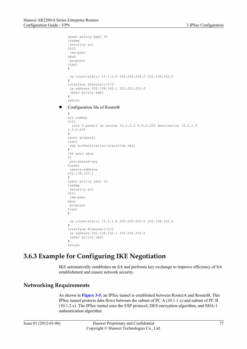
ipsec policy map1 10 isakmp security acl 3101 ike-peer spub proposal tran1 # ip route-static 10.1.2.0 255.255.255.0 202.138.163.2 # interface Ethernet1/0/0 ip address 202.138.163.1 255.255.255.0 ipsec policy map1 # return
l Configuration file of RouterB# acl number 3101 rule 5 permit ip source 10.1.2.0 0.0.0.255 destination 10.1.1.0 0.0.0.255 # ipsec proposal tran1 esp authentication-algorithm sha1 # ike peer spua v1 pre-shared-key huawei remote-address 202.138.163.1 # ipsec policy use1 10 isakmp security acl 3101 ike-peer spua proposal tran1 # ip route-static 10.1.1.0 255.255.255.0 202.138.162.2 # interface Ethernet1/0/0 ip address 202.138.162.1 255.255.255.0 ipsec policy use1 # return
3.6.3 Example for Configuring IKE NegotiationIKE automatically establishes an SA and performs key exchange to improve efficiency of SAestablishment and ensure network security.
Networking Requirements
As shown in Figure 3-5, an IPSec tunnel is established between RouterA and RouterB. ThisIPSec tunnel protects data flows between the subnet of PC A (10.1.1.x) and subnet of PC B(10.1.2.x). The IPSec tunnel uses the ESP protocol, DES encryption algorithm, and SHA-1authentication algorithm.
Huawei AR2200-S Series Enterprise RoutersConfiguration Guide - VPN 3 IPSec Configuration
Issue 01 (2012-01-06) Huawei Proprietary and ConfidentialCopyright © Huawei Technologies Co., Ltd.
77

Figure 3-5 Network diagram for configuring IKE negotiation
PC A PC B
RouterBRouterA
10.1.1.2/24 10.1.2.2/24
Eth 1/0/0 Eth 1/0/0
Internet
202.138.163.1/24 202.138.162.1/24
IPSec Tunnel
Configuration RoadmapThe configuration roadmap is as follows:
1. Configure IP addresses for interfaces.2. Configure an IKE proposal.3. Specify the local host ID and IKE peer for IKE negotiation.4. Configure Access Control Lists (ACLs) and define the data flows to be protected.5. Configure static routes to peers.6. Configure an IPSec proposal.7. Configure IPSec policies and apply the ACLs and IPSec proposal to the IPSec policies.8. Apply IPSec policies to interfaces.
Procedure
Step 1 Configure IP addresses for the interfaces on RouterA and RouterB.
# Assign an IP address to the interface of RouterA.
<Huawei> system-view[Huawei] interface ethernet 1/0/0[Huawei-Ethernet1/0/0] ip address 202.138.163.1 255.255.255.0[Huawei-Ethernet1/0/0] quit
# Assign an IP address to the interface of RouterB.
<Huawei> system-view[Huawei] interface ethernet 1/0/0 [Huawei-Ethernet1/0/0] ip address 202.138.162.1 255.255.255.0[Huawei-Ethernet1/0/0] quit
Step 2 Create an IKE proposal on RouterA and RouterB.
# Create the IKE proposal on RouterA.[Huawei] ike proposal 1[Huawei-ike-proposal-1] encryption-algorithm aes-cbc-128
Huawei AR2200-S Series Enterprise RoutersConfiguration Guide - VPN 3 IPSec Configuration
Issue 01 (2012-01-06) Huawei Proprietary and ConfidentialCopyright © Huawei Technologies Co., Ltd.
78

[Huawei-ike-proposal-1] authentication-algorithm md5[Huawei-ike-proposal-1] quit
# Create the IKE proposal on RouterB.
[Huawei] ike proposal 1[Huawei-ike-proposal-1] encryption-algorithm aes-cbc-128[Huawei-ike-proposal-1] authentication-algorithm md5[Huawei-ike-proposal-1] quit
Step 3 Configure local IDs and IKE peers on RouterA and RouterB.
# Configure the local ID and IKE peer on RouterA.
[Huawei] ike local-name huawei01[Huawei] ike peer spub v1[Huawei-ike-peer-spub] exchange-mode aggressive[Huawei-ike-peer-spub] ike-proposal 1[Huawei-ike-peer-spub] local-id-type name[Huawei-ike-peer-spub] pre-shared-key huawei[Huawei-ike-peer-spub] remote-name huawei02[Huawei-ike-peer-spub] remote-address 202.138.162.1[Huawei-ike-peer-spub] local-address 202.138.163.1[Huawei-ike-peer-spub] quit
NOTE
In aggressive mode, if the value of local-id-type is name, configure the IP address of the remote peer(remote-address x.x.x.x) on the local end.
# Configure the local ID and IKE peer on RouterB.
[Huawei] ike local-name huawei02[Huawei] ike peer spua v1[Huawei-ike-peer-spua] exchange-mode aggressive[Huawei-ike-peer-spua] ike-proposal 1[Huawei-ike-peer-spua] local-id-type name[Huawei-ike-peer-spua] pre-shared-key huawei[Huawei-ike-peer-spua] remote-name huawei01[Huawei-ike-peer-spua] remote-address 202.138.163.1[Huawei-ike-peer-spua] local-address 202.138.162.1[Huawei-ike-peer-spua] quit
Run the display ike peer command on RouterA and RouterB to view the configuration of theIKE peer. Take the display on RouterA as an example.
[Huawei] display ike peer name spub verbose---------------------------------------- Peer name : spub Exchange mode : aggressive on phase 1 Pre-shared-key : huawei Proposal : 1 Local ID type : Name DPD : Disable DPD mode : Periodic DPD idle time : 30 DPD retransmit interval : 15 DPD retry limit : 3 Peer Ip address : 202.138.162.1 VPN name : Local IP address : 202.138.163.1 Remote name : huawei02 Nat-traversal : Disable Configured IKE version : Version one ----------------------------------------
Huawei AR2200-S Series Enterprise RoutersConfiguration Guide - VPN 3 IPSec Configuration
Issue 01 (2012-01-06) Huawei Proprietary and ConfidentialCopyright © Huawei Technologies Co., Ltd.
79

Step 4 Configure ACLs on RouterA and RouterB to define the data flows to be protected.
# Configure an ACL on RouterA.
[Huawei] acl number 3101[Huawei-acl-adv-3101] rule permit ip source 10.1.1.0 0.0.0.255 destination 10.1.2.0 0.0.0.255[Huawei-acl-adv-3101] quit
# Configure an ACL on RouterB.
[Huawei] acl number 3101[Huawei-acl-adv-3101] rule permit ip source 10.1.2.0 0.0.0.255 destination 10.1.1.0 0.0.0.255[Huawei-acl-adv-3101] quit
Step 5 Configure static routes to the peers on RouterA and RouterB.
# Configure a static route to the peer on RouterA. In this example, the next hop to PCB is202.138.163.2.
[Huawei] ip route-static 10.1.2.0 255.255.255.0 202.138.163.2
# Configure a static route to the peer on RouterB. In this example, the next hop to PCA is202.138.162.2.
[Huawei] ip route-static 10.1.1.0 255.255.255.0 202.138.162.2
Step 6 Create an IPSec proposal on RouterA and RouterB.
# Create the IPSec proposal on RouterA.
[Huawei] ipsec proposal tran1[Huawei-ipsec-proposal-tran1] encapsulation-mode tunnel[Huawei-ipsec-proposal-tran1] transform esp[Huawei-ipsec-proposal-tran1] esp encryption-algorithm des[Huawei-ipsec-proposal-tran1] esp authentication-algorithm sha1[Huawei-ipsec-proposal-tran1] quit
# Create the IPSec proposal on RouterB.
[Huawei] ipsec proposal tran1[Huawei-ipsec-proposal-tran1] encapsulation-mode tunnel[Huawei-ipsec-proposal-tran1] transform esp[Huawei-ipsec-proposal-tran1] esp encryption-algorithm des[Huawei-ipsec-proposal-tran1] esp authentication-algorithm sha1[Huawei-ipsec-proposal-tran1] quit
Run the display ipsec proposal command on RouterA and RouterB to view the configurationof the IPSec proposal. Take the display on RouterA as an example.
[Huawei] display ipsec proposalNumber of Proposals: 1
IPsec proposal name: tran1 Encapsulation mode: Tunnel Transform : esp-new ESP protocol : Authentication SHA1-HMAC-96 Encryption DES
Step 7 Create IPSec policies on RouterA and RouterB.
# Create an IPSec policy on RouterA.
[Huawei] ipsec policy map1 10 isakmp[Huawei-ipsec-policy-isakmp-map1-10] ike-peer spub[Huawei-ipsec-policy-isakmp-map1-10] proposal tran1[Huawei-ipsec-policy-isakmp-map1-10] security acl 3101
Huawei AR2200-S Series Enterprise RoutersConfiguration Guide - VPN 3 IPSec Configuration
Issue 01 (2012-01-06) Huawei Proprietary and ConfidentialCopyright © Huawei Technologies Co., Ltd.
80

[Huawei-ipsec-policy-isakmp-map1-10] quit
# Create an IPSec policy on RouterB.
[Huawei] ipsec policy use1 10 isakmp[Huawei-ipsec-policy-isakmp-use1-10] ike-peer spua[Huawei-ipsec-policy-isakmp-use1-10] proposal tran1[Huawei-ipsec-policy-isakmp-use1-10] security acl 3101[Huawei-ipsec-policy-isakmp-use1-10] quit
Run the display ipsec policy command on RouterA and RouterB to view the configurations ofthe IPSec policies. Take the display on RouterA as an example.
[Huawei] display ipsec policy===========================================IPsec policy group: "map1"Using interface: {}===========================================
Sequence number: 10 Security data flow: 3101 Peer name: spub Perfect forward secrecy: None Proposal name: tran1 IPsec SA local duration(time based): 3600 seconds IPsec SA local duration(traffic based): 1843200 kilobytes SA trigger mode: Automatic
Step 8 Apply the IPSec policies to the interfaces of RouterA and RouterB.
# Apply the IPSec policy to the interface of RouterA.
[Huawei] interface ethernet 1/0/0[Huawei-Ethernet1/0/0] ipsec policy map1[Huawei-Ethernet1/0/0] quit
# Apply the IPSec policy to the interface of RouterB.
[Huawei] interface ethernet 1/0/0[Huawei-Ethernet1/0/0] ipsec policy use1[Huawei-Ethernet1/0/0] quit
Run the display ipsec sa command on RouterA and RouterB to view the configuration of theIPSec SAs. Take the display on RouterA as an example.
[Huawei] display ipsec sa===============================Interface: Ethernet 1/0/0 path MTU: 1500=============================== ----------------------------- IPsec policy name: "map1" sequence number: 10 mode: isakmp ----------------------------- Connection id: 3 encapsulation mode: tunnel tunnel local : 202.138.163.1 tunnel remote: 202.138.162.1 [inbound ESP SAs] spi: 1406123142 (0x53cfbc86) proposal: ESP-ENCRYPT-DES ESP-AUTH-SHA1 sa remaining key duration (bytes/sec): 1887436528/3575 max received sequence-number: 4 udp encapsulation used for nat traversal: N [outbound ESP SAs] spi: 3835455224 (0xe49c66f8) proposal: ESP-ENCRYPT-DES ESP-AUTH-SHA1 sa remaining key duration (bytes/sec): 1887436464/3575
Huawei AR2200-S Series Enterprise RoutersConfiguration Guide - VPN 3 IPSec Configuration
Issue 01 (2012-01-06) Huawei Proprietary and ConfidentialCopyright © Huawei Technologies Co., Ltd.
81

max sent sequence-number: 5 udp encapsulation used for nat traversal: N
Step 9 Verify the configurations.
After the configurations are complete, PC A can ping PC B successfully. The data transmittedbetween PC A and PC B is encrypted.
Run the display ike sa command on RouterA, and the following information is displayed:
[Huawei] display ike sa Conn-ID Peer VPN Flag(s) Phase --------------------------------------------------------- 14 202.138.162.1 0 RD|ST 1 16 202.138.162.1 0 RD|ST 2 Flag Description: RD--READY ST--STAYALIVE RL--REPLACED FD--FADING TO--TIMEOUT HRT--HEARTBEAT LKG--LAST KNOWN GOOD SEQ NO. BCK--BACKED UP
----End
Configuration Filesl Configuration file of RouterA
# acl number 3101 rule 5 permit ip source 10.1.1.0 0.0.0.255 destination 10.1.2.0 0.0.0.255 # ipsec proposal tran1 esp authentication-algorithm sha1 # ike proposal 1 encryption-algorithm aes-cbc-128 authentication-algorithm md5 # ike local-name huawei01 # ike peer spub v1 exchange-mode aggressive pre-shared-key huawei ike-proposal 1 local-id-type name remote-name huawei02 local-address 202.138.163.1 remote-address 202.138.162.1 # ipsec policy map1 10 isakmp security acl 3101 ike-peer spub proposal tran1 #
Huawei AR2200-S Series Enterprise RoutersConfiguration Guide - VPN 3 IPSec Configuration
Issue 01 (2012-01-06) Huawei Proprietary and ConfidentialCopyright © Huawei Technologies Co., Ltd.
82

ip route-static 10.1.2.0 255.255.255.0 202.138.163.2 # interface Ethernet1/0/0 ip address 202.138.163.1 255.255.255.0 ipsec policy map1 # return
l Configuration file of RouterB# acl number 3101 rule 5 permit ip source 10.1.2.0 0.0.0.255 destination 10.1.1.0 0.0.0.255 # ipsec proposal tran1 esp authentication-algorithm sha1 # ike proposal 1 encryption-algorithm aes-cbc-128 authentication-algorithm md5 # ike local-name huawei02 # ike peer spua v1 exchange-mode aggressive pre-shared-key huawei ike-proposal 1 local-id-type name remote-name huawei01 local-address 202.138.162.1 remote-address 202.138.163.1 # ipsec policy use1 10 isakmp security acl 3101 ike-peer spua proposal tran1 # ip route-static 10.1.1.0 255.255.255.0 202.138.162.2 # interface Ethernet1/0/0 ip address 202.138.162.1 255.255.255.0 ipsec policy use1 # return
Huawei AR2200-S Series Enterprise RoutersConfiguration Guide - VPN 3 IPSec Configuration
Issue 01 (2012-01-06) Huawei Proprietary and ConfidentialCopyright © Huawei Technologies Co., Ltd.
83
Related Documents