Configuration Fundamentals Command Reference, Cisco IOS XE Release 3SE (Catalyst 5700 Switches) Americas Headquarters Cisco Systems, Inc. 170 West Tasman Drive San Jose, CA 95134-1706 USA http://www.cisco.com Tel: 408 526-4000 800 553-NETS (6387) Fax: 408 527-0883

Welcome message from author
This document is posted to help you gain knowledge. Please leave a comment to let me know what you think about it! Share it to your friends and learn new things together.
Transcript
Configuration Fundamentals Command Reference, Cisco IOS XERelease 3SE (Catalyst 5700 Switches)
Americas HeadquartersCisco Systems, Inc.170 West Tasman DriveSan Jose, CA 95134-1706USAhttp://www.cisco.comTel: 408 526-4000 800 553-NETS (6387)Fax: 408 527-0883

© 2013 Cisco Systems, Inc. All rights reserved.
C O N T E N T S
C H A P T E R 1 Configuration Fundamentals Commands 1
Configuration Fundamentals Commands 1
archive tar 2
boot system 5
copy 12
debug installer 32
debug iosd issu 34
define interface-range 35
enable 37
erase 41
errdisable detect cause 45
errdisable recovery 47
file verify auto 50
hostname 52
reload 54
remote-span 58
setup 59
show debugging 65
show hosts 68
show inventory 72
show pagp 76
show processes cpu 78
show running-config 90
show software authenticity file 98
show software authenticity keys 101
show software authenticity running 103
show software installer rollback-timer 106
show software package 108
Configuration Fundamentals Command Reference, Cisco IOS XE Release 3SE (Catalyst 5700 Switches) iii
show version 112
software auto-upgrade 137
software clean 139
software commit 142
software expand 145
software install file 149
software install source switch 153
software rollback 156
test cable-diagnostics 159
traceroute mac 161
upgrade rom-monitor 165
verify 170
vtp 175
Configuration Fundamentals Command Reference, Cisco IOS XE Release 3SE (Catalyst 5700 Switches)iv
Contents
Configuration Fundamentals Commands
• Configuration Fundamentals Commands, page 1
Configuration Fundamentals Commands
Configuration Fundamentals Command Reference, Cisco IOS XE Release 3SE (Catalyst 5700 Switches) 1
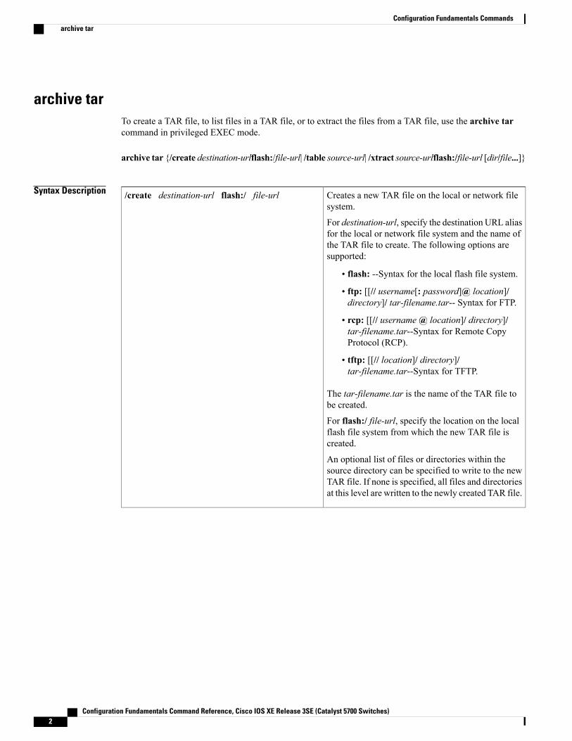
archive tarTo create a TAR file, to list files in a TAR file, or to extract the files from a TAR file, use the archive tarcommand in privileged EXEC mode.
archive tar {/create destination-urlflash:/file-url| /table source-url| /xtract source-urlflash:/file-url [dir/file...]}
Syntax Description Creates a new TAR file on the local or network filesystem.
For destination-url, specify the destination URL aliasfor the local or network file system and the name ofthe TAR file to create. The following options aresupported:
• flash: --Syntax for the local flash file system.
• ftp: [[// username[: password]@ location]/directory]/ tar-filename.tar-- Syntax for FTP.
• rcp: [[// username@ location]/ directory]/tar-filename.tar--Syntax for Remote CopyProtocol (RCP).
• tftp: [[// location]/ directory]/tar-filename.tar--Syntax for TFTP.
The tar-filename.tar is the name of the TAR file tobe created.
For flash:/ file-url, specify the location on the localflash file system from which the new TAR file iscreated.
An optional list of files or directories within thesource directory can be specified to write to the newTAR file. If none is specified, all files and directoriesat this level are written to the newly created TAR file.
/create destination-url flash:/ file-url
Configuration Fundamentals Command Reference, Cisco IOS XE Release 3SE (Catalyst 5700 Switches)2
Configuration Fundamentals Commandsarchive tar
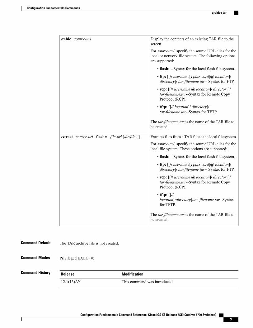
Display the contents of an existing TAR file to thescreen.
For source-url, specify the source URL alias for thelocal or network file system. The following optionsare supported:
• flash: --Syntax for the local flash file system.
• ftp: [[// username[: password]@ location]/directory]/ tar-filename.tar-- Syntax for FTP.
• rcp: [[// username@ location]/ directory]/tar-filename.tar--Syntax for Remote CopyProtocol (RCP).
• tftp: [[// location]/ directory]/tar-filename.tar--Syntax for TFTP.
The tar-filename.tar is the name of the TAR file tobe created.
/table source-url
Extracts files from a TAR file to the local file system.
For source-url, specify the source URL alias for thelocal file system. These options are supported:
• flash: --Syntax for the local flash file system.
• ftp: [[// username[: password]@ location]/directory]/ tar-filename.tar-- Syntax for FTP.
• rcp: [[// username@ location]/ directory]/tar-filename.tar--Syntax for Remote CopyProtocol (RCP).
• tftp: [[//location]/directory]/tar-filename.tar--Syntaxfor TFTP.
The tar-filename.tar is the name of the TAR file tobe created.
/xtract source-url flash:/ file-url [dir/file...]
Command Default The TAR archive file is not created.
Command Modes Privileged EXEC (#)
Command History ModificationRelease
This command was introduced.12.1(13)AY
Configuration Fundamentals Command Reference, Cisco IOS XE Release 3SE (Catalyst 5700 Switches) 3
Configuration Fundamentals Commandsarchive tar
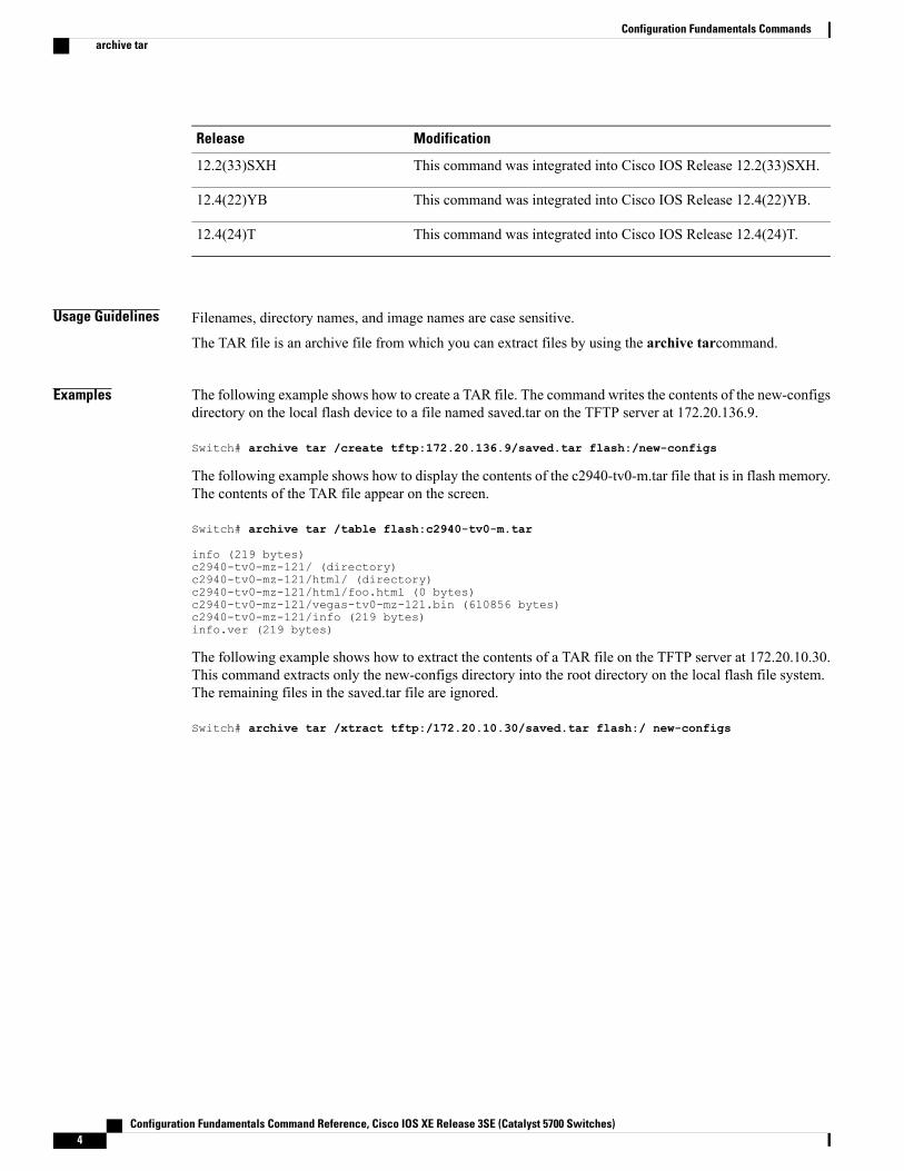
ModificationRelease
This command was integrated into Cisco IOS Release 12.2(33)SXH.12.2(33)SXH
This command was integrated into Cisco IOS Release 12.4(22)YB.12.4(22)YB
This command was integrated into Cisco IOS Release 12.4(24)T.12.4(24)T
Usage Guidelines Filenames, directory names, and image names are case sensitive.
The TAR file is an archive file from which you can extract files by using the archive tarcommand.
Examples The following example shows how to create a TAR file. The command writes the contents of the new-configsdirectory on the local flash device to a file named saved.tar on the TFTP server at 172.20.136.9.
Switch# archive tar /create tftp:172.20.136.9/saved.tar flash:/new-configs
The following example shows how to display the contents of the c2940-tv0-m.tar file that is in flash memory.The contents of the TAR file appear on the screen.
Switch# archive tar /table flash:c2940-tv0-m.tar
info (219 bytes)c2940-tv0-mz-121/ (directory)c2940-tv0-mz-121/html/ (directory)c2940-tv0-mz-121/html/foo.html (0 bytes)c2940-tv0-mz-121/vegas-tv0-mz-121.bin (610856 bytes)c2940-tv0-mz-121/info (219 bytes)info.ver (219 bytes)
The following example shows how to extract the contents of a TAR file on the TFTP server at 172.20.10.30.This command extracts only the new-configs directory into the root directory on the local flash file system.The remaining files in the saved.tar file are ignored.
Switch# archive tar /xtract tftp:/172.20.10.30/saved.tar flash:/ new-configs
Configuration Fundamentals Command Reference, Cisco IOS XE Release 3SE (Catalyst 5700 Switches)4
Configuration Fundamentals Commandsarchive tar
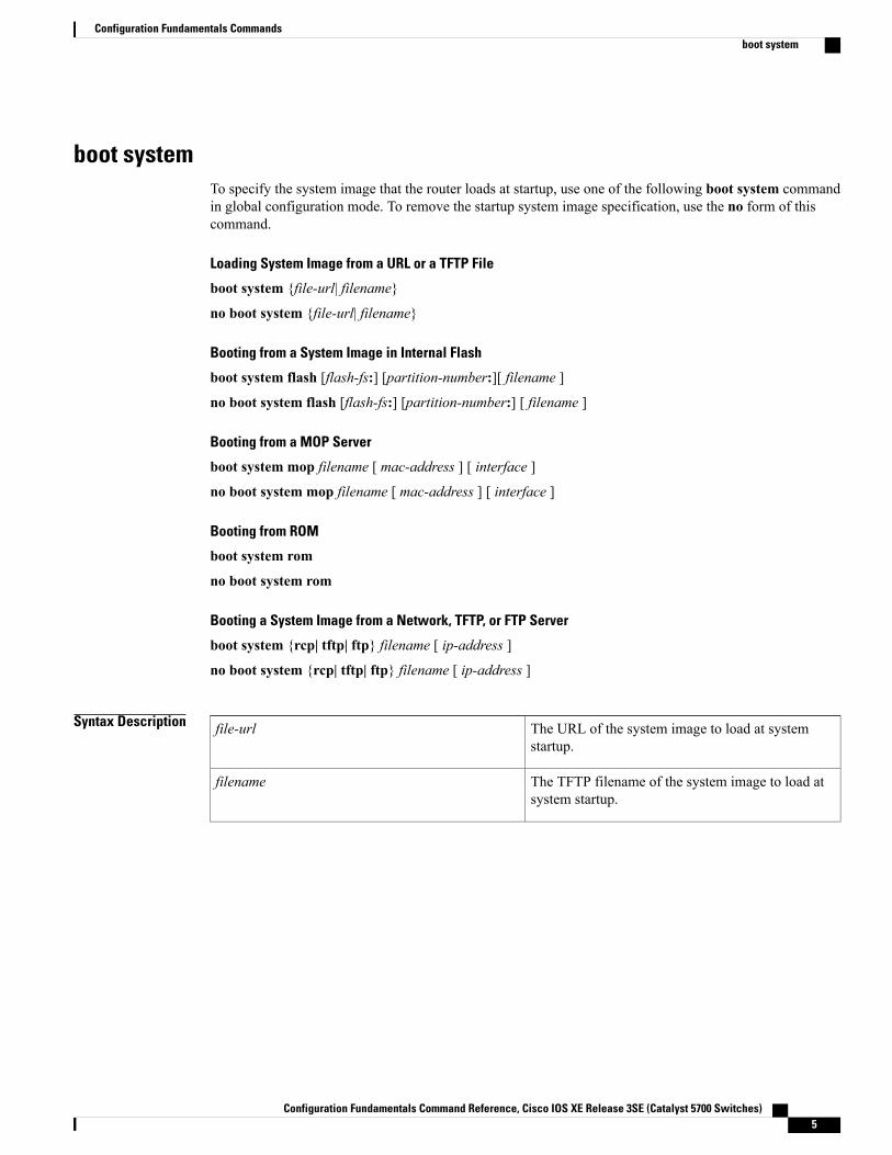
boot systemTo specify the system image that the router loads at startup, use one of the following boot system commandin global configuration mode. To remove the startup system image specification, use the no form of thiscommand.
Loading System Image from a URL or a TFTP File
boot system {file-url| filename}
no boot system {file-url| filename}
Booting from a System Image in Internal Flash
boot system flash [flash-fs:] [partition-number:][ filename ]
no boot system flash [flash-fs:] [partition-number:] [ filename ]
Booting from a MOP Server
boot system mop filename [ mac-address ] [ interface ]
no boot system mop filename [ mac-address ] [ interface ]
Booting from ROM
boot system rom
no boot system rom
Booting a System Image from a Network, TFTP, or FTP Server
boot system {rcp| tftp| ftp} filename [ ip-address ]
no boot system {rcp| tftp| ftp} filename [ ip-address ]
Syntax Description The URL of the system image to load at systemstartup.
file-url
The TFTP filename of the system image to load atsystem startup.
filename
Configuration Fundamentals Command Reference, Cisco IOS XE Release 3SE (Catalyst 5700 Switches) 5
Configuration Fundamentals Commandsboot system
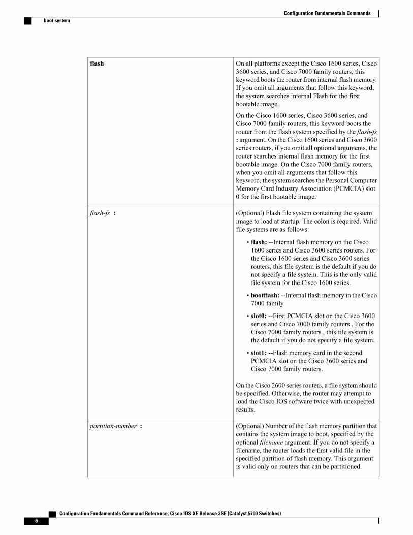
On all platforms except the Cisco 1600 series, Cisco3600 series, and Cisco 7000 family routers, thiskeyword boots the router from internal flash memory.If you omit all arguments that follow this keyword,the system searches internal Flash for the firstbootable image.
On the Cisco 1600 series, Cisco 3600 series, andCisco 7000 family routers, this keyword boots therouter from the flash system specified by the flash-fs: argument. On the Cisco 1600 series and Cisco 3600series routers, if you omit all optional arguments, therouter searches internal flash memory for the firstbootable image. On the Cisco 7000 family routers,when you omit all arguments that follow thiskeyword, the system searches the Personal ComputerMemory Card Industry Association (PCMCIA) slot0 for the first bootable image.
flash
(Optional) Flash file system containing the systemimage to load at startup. The colon is required. Validfile systems are as follows:
• flash: --Internal flash memory on the Cisco1600 series and Cisco 3600 series routers. Forthe Cisco 1600 series and Cisco 3600 seriesrouters, this file system is the default if you donot specify a file system. This is the only validfile system for the Cisco 1600 series.
• bootflash: --Internal flash memory in the Cisco7000 family.
• slot0: --First PCMCIA slot on the Cisco 3600series and Cisco 7000 family routers . For theCisco 7000 family routers , this file system isthe default if you do not specify a file system.
• slot1: --Flash memory card in the secondPCMCIA slot on the Cisco 3600 series andCisco 7000 family routers.
On the Cisco 2600 series routers, a file system shouldbe specified. Otherwise, the router may attempt toload the Cisco IOS software twice with unexpectedresults.
flash-fs :
(Optional) Number of the flash memory partition thatcontains the system image to boot, specified by theoptional filename argument. If you do not specify afilename, the router loads the first valid file in thespecified partition of flash memory. This argumentis valid only on routers that can be partitioned.
partition-number :
Configuration Fundamentals Command Reference, Cisco IOS XE Release 3SE (Catalyst 5700 Switches)6
Configuration Fundamentals Commandsboot system
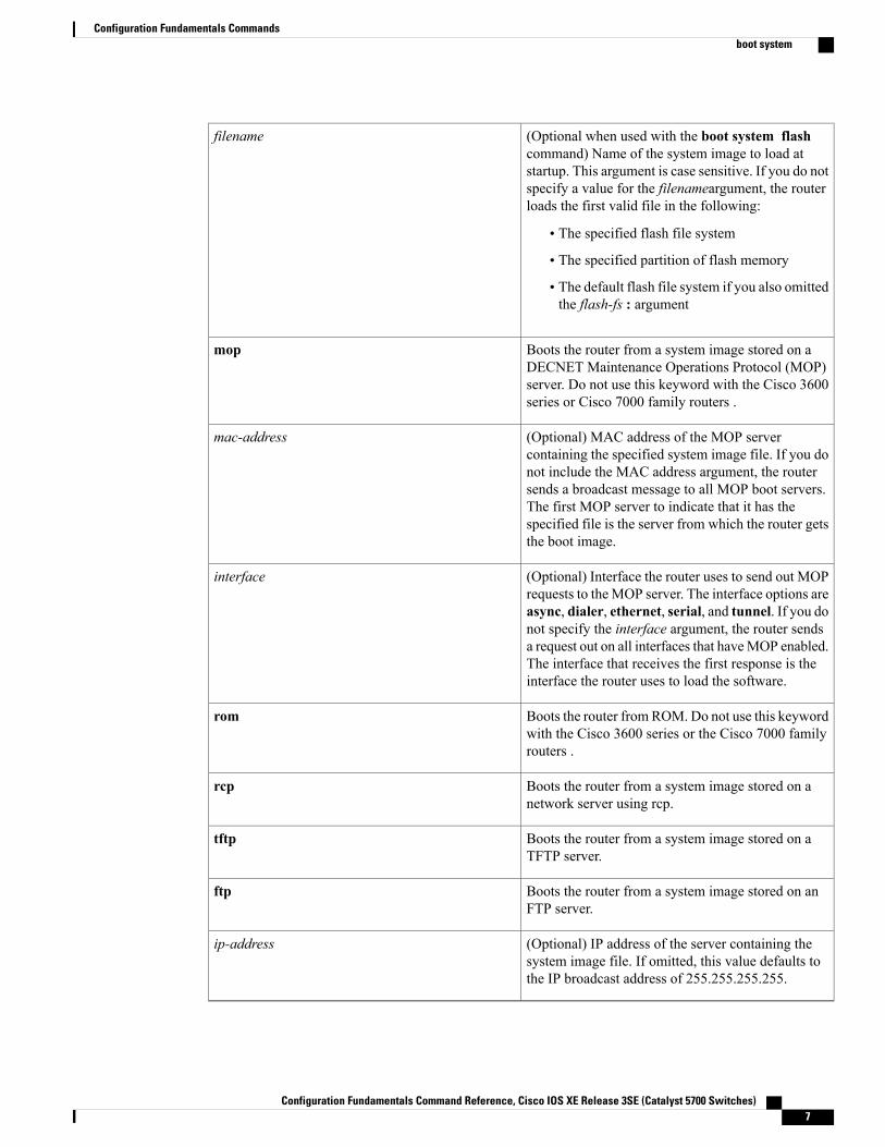
(Optional when used with the boot system flashcommand) Name of the system image to load atstartup. This argument is case sensitive. If you do notspecify a value for the filenameargument, the routerloads the first valid file in the following:
• The specified flash file system
• The specified partition of flash memory
• The default flash file system if you also omittedthe flash-fs : argument
filename
Boots the router from a system image stored on aDECNET Maintenance Operations Protocol (MOP)server. Do not use this keyword with the Cisco 3600series or Cisco 7000 family routers .
mop
(Optional) MAC address of the MOP servercontaining the specified system image file. If you donot include the MAC address argument, the routersends a broadcast message to all MOP boot servers.The first MOP server to indicate that it has thespecified file is the server from which the router getsthe boot image.
mac-address
(Optional) Interface the router uses to send out MOPrequests to theMOP server. The interface options areasync, dialer, ethernet, serial, and tunnel. If you donot specify the interface argument, the router sendsa request out on all interfaces that haveMOP enabled.The interface that receives the first response is theinterface the router uses to load the software.
interface
Boots the router fromROM. Do not use this keywordwith the Cisco 3600 series or the Cisco 7000 familyrouters .
rom
Boots the router from a system image stored on anetwork server using rcp.
rcp
Boots the router from a system image stored on aTFTP server.
tftp
Boots the router from a system image stored on anFTP server.
ftp
(Optional) IP address of the server containing thesystem image file. If omitted, this value defaults tothe IP broadcast address of 255.255.255.255.
ip-address
Configuration Fundamentals Command Reference, Cisco IOS XE Release 3SE (Catalyst 5700 Switches) 7
Configuration Fundamentals Commandsboot system
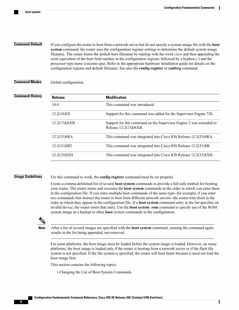
Command Default If you configure the router to boot from a network server but do not specify a system image file with the bootsystem command, the router uses the configuration register settings to determine the default system imagefilename. The router forms the default boot filename by starting with the word cisco and then appending theoctal equivalent of the boot field number in the configuration register, followed by a hyphen (-) and theprocessor type name (cisconn-cpu). Refer to the appropriate hardware installation guide for details on theconfiguration register and default filename. See also the config-register or confreg command.
Command Modes Global configuration
Command History ModificationRelease
This command was introduced.10.0
Support for this command was added for the Supervisor Engine 720.12.2(14)SX
Support for this command on the Supervisor Engine 2 was extended toRelease 12.2(17d)SXB.
12.2(17d)SXB
This command was integrated into Cisco IOS Release 12.2(33)SRA.12.2(33)SRA
This command was integrated into Cisco IOS Release 12.2(31)SB.12.2(31)SB2
This command was integrated into Cisco IOS Release 12.2(33)SXH.12.2(33)SXH
Usage Guidelines For this command to work, the config-register command must be set properly.
Create a comma-delimited list of several boot system commands to provide a fail-safe method for bootingyour router. The router stores and executes the boot system commands in the order in which you enter themin the configuration file. If you enter multiple boot commands of the same type--for example, if you entertwo commands that instruct the router to boot from different network servers--the router tries them in theorder in which they appear in the configuration file. If a boot system command entry in the list specifies aninvalid device, the router omits that entry. Use the boot system rom command to specify use of the ROMsystem image as a backup to other boot system commands in the configuration.
After a list of several images are specified with the boot system command, running the command againresults in the list being appended, not removed.
Note
For some platforms, the boot image must be loaded before the system image is loaded. However, on manyplatforms, the boot image is loaded only if the router is booting from a network server or if the flash filesystem is not specified. If the file system is specified, the router will boot faster because it need not load theboot image first.
This section contains the following topics:
• Changing the List of Boot System Commands
Configuration Fundamentals Command Reference, Cisco IOS XE Release 3SE (Catalyst 5700 Switches)8
Configuration Fundamentals Commandsboot system
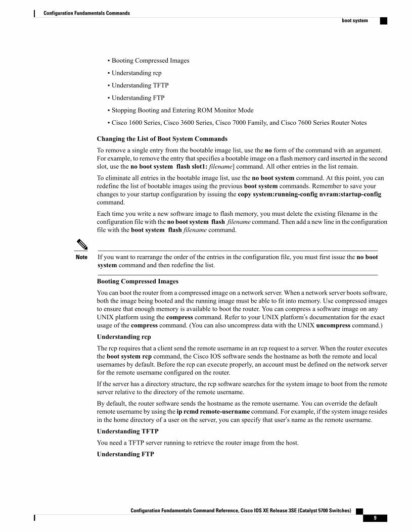
• Booting Compressed Images
• Understanding rcp
• Understanding TFTP
• Understanding FTP
• Stopping Booting and Entering ROM Monitor Mode
• Cisco 1600 Series, Cisco 3600 Series, Cisco 7000 Family, and Cisco 7600 Series Router Notes
Changing the List of Boot System Commands
To remove a single entry from the bootable image list, use the no form of the command with an argument.For example, to remove the entry that specifies a bootable image on a flash memory card inserted in the secondslot, use the no boot system flash slot1: filename] command. All other entries in the list remain.
To eliminate all entries in the bootable image list, use the no boot system command. At this point, you canredefine the list of bootable images using the previous boot system commands. Remember to save yourchanges to your startup configuration by issuing the copy system:running-config nvram:startup-configcommand.
Each time you write a new software image to flash memory, you must delete the existing filename in theconfiguration file with the no boot system flash filename command. Then add a new line in the configurationfile with the boot system flash filename command.
If you want to rearrange the order of the entries in the configuration file, you must first issue the no bootsystem command and then redefine the list.
Note
Booting Compressed Images
You can boot the router from a compressed image on a network server. When a network server boots software,both the image being booted and the running image must be able to fit into memory. Use compressed imagesto ensure that enough memory is available to boot the router. You can compress a software image on anyUNIX platform using the compress command. Refer to your UNIX platform’s documentation for the exactusage of the compress command. (You can also uncompress data with the UNIX uncompress command.)
Understanding rcp
The rcp requires that a client send the remote username in an rcp request to a server. When the router executesthe boot system rcp command, the Cisco IOS software sends the hostname as both the remote and localusernames by default. Before the rcp can execute properly, an account must be defined on the network serverfor the remote username configured on the router.
If the server has a directory structure, the rcp software searches for the system image to boot from the remoteserver relative to the directory of the remote username.
By default, the router software sends the hostname as the remote username. You can override the defaultremote username by using the ip rcmd remote-username command. For example, if the system image residesin the home directory of a user on the server, you can specify that user’s name as the remote username.Understanding TFTP
You need a TFTP server running to retrieve the router image from the host.
Understanding FTP
Configuration Fundamentals Command Reference, Cisco IOS XE Release 3SE (Catalyst 5700 Switches) 9
Configuration Fundamentals Commandsboot system
You need an FTP server running to retrieve the router image from the host. You also need an account on theserver or anonymous file access to the server.
Stopping Booting and Entering ROMMonitor Mode
During the first 60 seconds of startup, you can force the router to stop booting by pressing the Break key. Therouter will enter ROMmonitor mode, where you can change the configuration register value or boot the routermanually.
Cisco 1600 Series, Cisco 3600 Series, Cisco 7000 Family, and Cisco 7600 Series Router Notes
For the Cisco 3600 series and Cisco 7000 family, the boot system command modifies the BOOT variable inthe running configuration. The BOOT variable specifies a list of bootable images on various devices.
When you use the boot system command on the Cisco 1600 series, Cisco 3600 series, Cisco 7000 family,and Cisco 7600 series, you affect only the running configuration. You must save the BOOT variablesettings to your startup configuration to place the information under ROM monitor control and to havethe variable function as expected. Use the copy system:running-config nvram:startup-config privilegedEXEC command to save the variable from your running configuration to your startup configuration.
Note
To display the contents of the BOOT variable, use the show bootvar EXEC command.
Examples The following example illustrates a configuration that specifies two possible internetwork locations for asystem image, with the ROM software being used as a backup:
Router(config)# boot system tftp://192.168.7.24/cs3-rx.90-1
Router(config)# boot system tftp://192.168.7.19/cs3-rx.83-2
Router(config)# boot system romThe following example boots the system boot relocatable image file named igs-bpx-l from partition 2 of theflash device:
Router(config)# boot system flash:2:igs-bpx-lThe following example instructs the router to boot from an image located on the flash memory card insertedin slot 0:
Router(config)# boot system slot0:new-configThe following example specifies the file named new-ios-image as the system image for a Cisco 3600 seriesrouter to load at startup. This file is located in the fourth partition of the flash memory card in slot 0.
Router(config)# boot system slot0:4:dirt/images/new-ios-imageThis example boots from the image fi le named c1600-y-l in part ition 2 of flash memory of a Cisco 1600series router:
Router(config)# boot system flash:2:c1600-y-l
Related Commands DescriptionCommand
Boots the router manually.boot
Changes the configuration register settings.config-register
Configuration Fundamentals Command Reference, Cisco IOS XE Release 3SE (Catalyst 5700 Switches)10
Configuration Fundamentals Commandsboot system
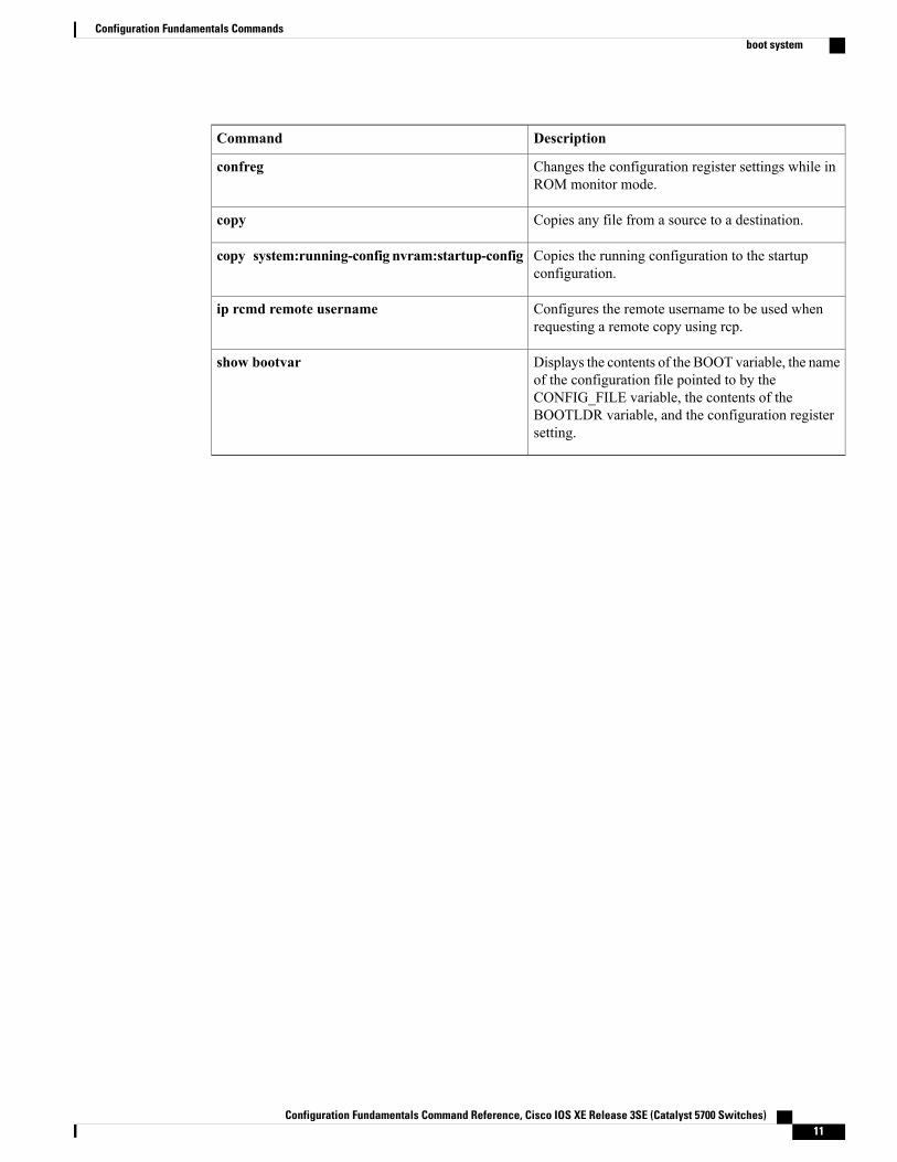
DescriptionCommand
Changes the configuration register settings while inROM monitor mode.
confreg
Copies any file from a source to a destination.copy
Copies the running configuration to the startupconfiguration.
copy system:running-config nvram:startup-config
Configures the remote username to be used whenrequesting a remote copy using rcp.
ip rcmd remote username
Displays the contents of the BOOT variable, the nameof the configuration file pointed to by theCONFIG_FILE variable, the contents of theBOOTLDR variable, and the configuration registersetting.
show bootvar
Configuration Fundamentals Command Reference, Cisco IOS XE Release 3SE (Catalyst 5700 Switches) 11
Configuration Fundamentals Commandsboot system
copyTo copy any file from a source to a destination, use the copy command in privileged EXEC or diagnosticmode.
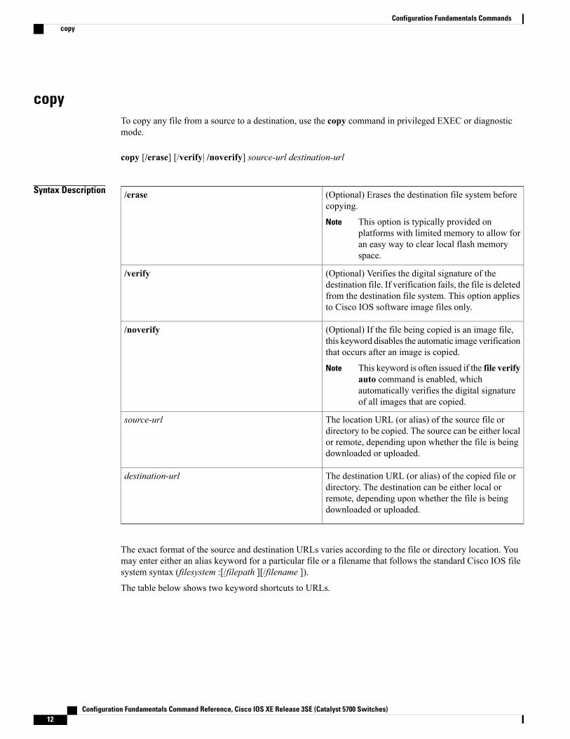
copy [/erase] [/verify| /noverify] source-url destination-url
Syntax Description (Optional) Erases the destination file system beforecopying.
This option is typically provided onplatforms with limited memory to allow foran easy way to clear local flash memoryspace.
Note
/erase
(Optional) Verifies the digital signature of thedestination file. If verification fails, the file is deletedfrom the destination file system. This option appliesto Cisco IOS software image files only.
/verify
(Optional) If the file being copied is an image file,this keyword disables the automatic image verificationthat occurs after an image is copied.
This keyword is often issued if the file verifyauto command is enabled, whichautomatically verifies the digital signatureof all images that are copied.
Note
/noverify
The location URL (or alias) of the source file ordirectory to be copied. The source can be either localor remote, depending upon whether the file is beingdownloaded or uploaded.
source-url
The destination URL (or alias) of the copied file ordirectory. The destination can be either local orremote, depending upon whether the file is beingdownloaded or uploaded.
destination-url
The exact format of the source and destination URLs varies according to the file or directory location. Youmay enter either an alias keyword for a particular file or a filename that follows the standard Cisco IOS filesystem syntax (filesystem :[/filepath ][/filename ]).
The table below shows two keyword shortcuts to URLs.
Configuration Fundamentals Command Reference, Cisco IOS XE Release 3SE (Catalyst 5700 Switches)12
Configuration Fundamentals Commandscopy
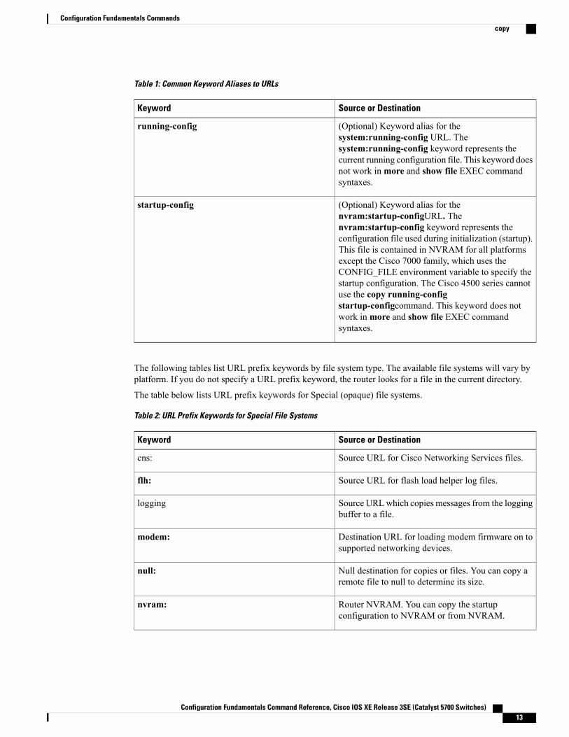
Table 1: Common Keyword Aliases to URLs
Source or DestinationKeyword
(Optional) Keyword alias for thesystem:running-config URL. Thesystem:running-config keyword represents thecurrent running configuration file. This keyword doesnot work inmore and show file EXEC commandsyntaxes.
running-config
(Optional) Keyword alias for thenvram:startup-configURL. Thenvram:startup-config keyword represents theconfiguration file used during initialization (startup).This file is contained in NVRAM for all platformsexcept the Cisco 7000 family, which uses theCONFIG_FILE environment variable to specify thestartup configuration. The Cisco 4500 series cannotuse the copy running-configstartup-configcommand. This keyword does notwork inmore and show file EXEC commandsyntaxes.
startup-config
The following tables list URL prefix keywords by file system type. The available file systems will vary byplatform. If you do not specify a URL prefix keyword, the router looks for a file in the current directory.
The table below lists URL prefix keywords for Special (opaque) file systems.
Table 2: URL Prefix Keywords for Special File Systems
Source or DestinationKeyword
Source URL for Cisco Networking Services files.cns:
Source URL for flash load helper log files.flh:
Source URLwhich copies messages from the loggingbuffer to a file.
logging
Destination URL for loading modem firmware on tosupported networking devices.
modem:
Null destination for copies or files. You can copy aremote file to null to determine its size.
null:
Router NVRAM. You can copy the startupconfiguration to NVRAM or from NVRAM.
nvram:
Configuration Fundamentals Command Reference, Cisco IOS XE Release 3SE (Catalyst 5700 Switches) 13
Configuration Fundamentals Commandscopy
Source or DestinationKeyword
Source or destination URL for Onboard FailureLogging files.
obfl:
Router NVRAM on the standby hardware. You cancopy the startup configuration to NVRAM or fromNVRAM.
stby-nvram:
Source or destination URL for Onboard FailureLogging files on the standby hardware.
stby-obfl:
Source or destinationURL for systemmemory, whichincludes the running configuration.
system:
Source URL for the archive file system.tar:
Source or destination URL for the temporary systemfiles.
tmpsys:
Source or destination for a file from a networkmachine that uses the Xmodem protocol.
xmodem:
Source or destination for a file from a networkmachine that uses the Ymodem protocol.
ymodem:
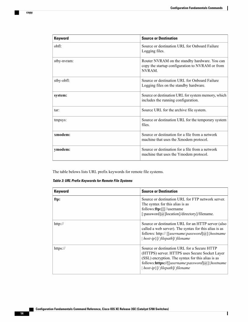
The table belows lists URL prefix keywords for remote file systems.
Table 3: URL Prefix Keywords for Remote File Systems
Source or DestinationKeyword
Source or destination URL for FTP network server.The syntax for this alias is asfollows:ftp:[[[//username[:password]@]location]/directory]/filename.
ftp:
Source or destination URL for an HTTP server (alsocalled a web server). The syntax for this alias is asfollows: http:// [[username:password]@]{hostname| host-ip}[/ filepath]/ filename
http://
Source or destination URL for a Secure HTTP(HTTPS) server. HTTPS uses Secure Socket Layer(SSL) encryption. The syntax for this alias is asfollows:https://[[username:password]@]{hostname| host-ip}[/ filepath]/ filename
https://
Configuration Fundamentals Command Reference, Cisco IOS XE Release 3SE (Catalyst 5700 Switches)14
Configuration Fundamentals Commandscopy
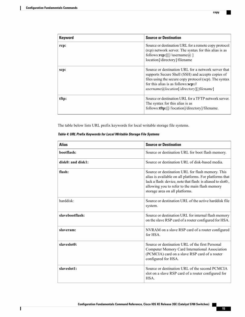
Source or DestinationKeyword
Source or destination URL for a remote copy protocol(rcp) network server. The syntax for this alias is asfollows:rcp:[[[//username@ ]location]/directory]/filename
rcp:
Source or destination URL for a network server thatsupports Secure Shell (SSH) and accepts copies offiles using the secure copy protocol (scp). The syntaxfor this alias is as follows:scp://username@location[/directory][/filename]
scp:
Source or destinationURL for a TFTP network server.The syntax for this alias is asfollows:tftp:[[//location]/directory]/filename.
tftp:
The table below lists URL prefix keywords for local writable storage file systems.
Table 4: URL Prefix Keywords for Local Writable Storage File Systems
Source or DestinationAlias
Source or destination URL for boot flash memory.bootflash:
Source or destination URL of disk-based media.disk0: and disk1:
Source or destination URL for flash memory. Thisalias is available on all platforms. For platforms thatlack a flash: device, note that flash: is aliased to slot0:,allowing you to refer to the main flash memorystorage area on all platforms.
flash:
Source or destination URL of the active harddisk filesystem.
harddisk:
Source or destination URL for internal flash memoryon the slave RSP card of a router configured for HSA.
slavebootflash:
NVRAM on a slave RSP card of a router configuredfor HSA.
slaveram:
Source or destination URL of the first PersonalComputer Memory Card International Association(PCMCIA) card on a slave RSP card of a routerconfigured for HSA.
slaveslot0:
Source or destination URL of the second PCMCIAslot on a slave RSP card of a router configured forHSA.
slaveslot1:
Configuration Fundamentals Command Reference, Cisco IOS XE Release 3SE (Catalyst 5700 Switches) 15
Configuration Fundamentals Commandscopy
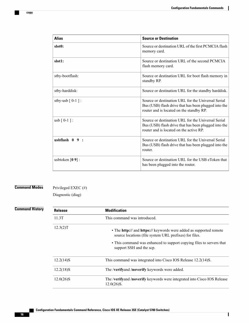
Source or DestinationAlias
Source or destinationURL of the first PCMCIA flashmemory card.
slot0:
Source or destination URL of the second PCMCIAflash memory card.
slot1:
Source or destination URL for boot flash memory instandby RP.
stby-bootflash:
Source or destination URL for the standby harddisk.stby-harddisk:
Source or destination URL for the Universal SerialBus (USB) flash drive that has been plugged into therouter and is located on the standby RP.
stby-usb [ 0-1 ] :
Source or destination URL for the Universal SerialBus (USB) flash drive that has been plugged into therouter and is located on the active RP.
usb [ 0-1 ] :
Source or destination URL for the Universal SerialBus (USB) flash drive that has been plugged into therouter.
usbflash 0 9 :
Source or destination URL for the USB eToken thathas been plugged into the router.
usbtoken [0 9] :
Command Modes Privileged EXEC (#)
Diagnostic (diag)
Command History ModificationRelease
This command was introduced.11.3T
• The http:// and https:// keywords were added as supported remotesource locations (file system URL prefixes) for files.
• This command was enhanced to support copying files to servers thatsupport SSH and the scp.
12.3(2)T
This command was integrated into Cisco IOS Release 12.2(14)S.12.2(14)S
The /verifyand /noverify keywords were added.12.2(18)S
The /verifyand /noverify keywords were integrated into Cisco IOS Release12.0(26)S.
12.0(26)S
Configuration Fundamentals Command Reference, Cisco IOS XE Release 3SE (Catalyst 5700 Switches)16
Configuration Fundamentals Commandscopy
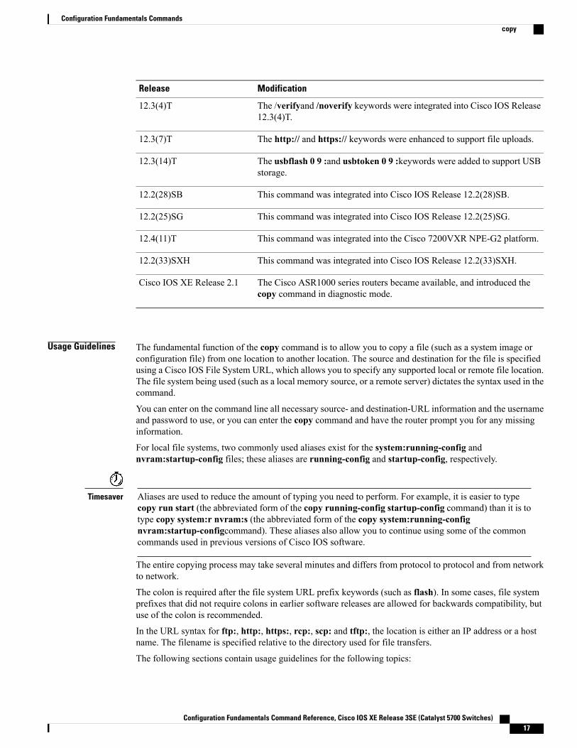
ModificationRelease
The /verifyand /noverify keywords were integrated into Cisco IOS Release12.3(4)T.
12.3(4)T
The http:// and https:// keywords were enhanced to support file uploads.12.3(7)T
The usbflash 0 9 :and usbtoken 0 9 :keywords were added to support USBstorage.
12.3(14)T
This command was integrated into Cisco IOS Release 12.2(28)SB.12.2(28)SB
This command was integrated into Cisco IOS Release 12.2(25)SG.12.2(25)SG
This command was integrated into the Cisco 7200VXR NPE-G2 platform.12.4(11)T
This command was integrated into Cisco IOS Release 12.2(33)SXH.12.2(33)SXH
The Cisco ASR1000 series routers became available, and introduced thecopy command in diagnostic mode.
Cisco IOS XE Release 2.1
Usage Guidelines The fundamental function of the copy command is to allow you to copy a file (such as a system image orconfiguration file) from one location to another location. The source and destination for the file is specifiedusing a Cisco IOS File System URL, which allows you to specify any supported local or remote file location.The file system being used (such as a local memory source, or a remote server) dictates the syntax used in thecommand.
You can enter on the command line all necessary source- and destination-URL information and the usernameand password to use, or you can enter the copy command and have the router prompt you for any missinginformation.
For local file systems, two commonly used aliases exist for the system:running-config andnvram:startup-config files; these aliases are running-config and startup-config, respectively.
Aliases are used to reduce the amount of typing you need to perform. For example, it is easier to typecopy run start (the abbreviated form of the copy running-config startup-config command) than it is totype copy system:r nvram:s (the abbreviated form of the copy system:running-confignvram:startup-configcommand). These aliases also allow you to continue using some of the commoncommands used in previous versions of Cisco IOS software.
Timesaver
The entire copying process may take several minutes and differs from protocol to protocol and from networkto network.
The colon is required after the file system URL prefix keywords (such as flash). In some cases, file systemprefixes that did not require colons in earlier software releases are allowed for backwards compatibility, butuse of the colon is recommended.
In the URL syntax for ftp:, http:, https:, rcp:, scp: and tftp:, the location is either an IP address or a hostname. The filename is specified relative to the directory used for file transfers.
The following sections contain usage guidelines for the following topics:
Configuration Fundamentals Command Reference, Cisco IOS XE Release 3SE (Catalyst 5700 Switches) 17
Configuration Fundamentals Commandscopy
Understanding Invalid Combinations of Source and Destination
Some invalid combinations of source and destination exist. Specifically, you cannot copy:
• From a running configuration to a running configuration
• From a startup configuration to a startup configuration
• From a device to the same device (for example, the copy flash: flash: command is invalid)
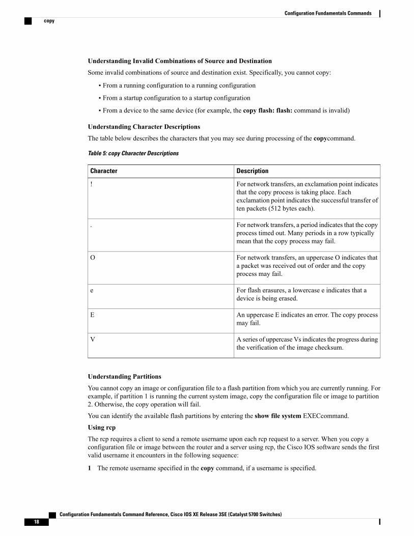
Understanding Character Descriptions
The table below describes the characters that you may see during processing of the copycommand.
Table 5: copy Character Descriptions
DescriptionCharacter
For network transfers, an exclamation point indicatesthat the copy process is taking place. Eachexclamation point indicates the successful transfer often packets (512 bytes each).
!
For network transfers, a period indicates that the copyprocess timed out. Many periods in a row typicallymean that the copy process may fail.
.
For network transfers, an uppercase O indicates thata packet was received out of order and the copyprocess may fail.
O
For flash erasures, a lowercase e indicates that adevice is being erased.
e
An uppercase E indicates an error. The copy processmay fail.
E
A series of uppercase Vs indicates the progress duringthe verification of the image checksum.
V
Understanding Partitions
You cannot copy an image or configuration file to a flash partition from which you are currently running. Forexample, if partition 1 is running the current system image, copy the configuration file or image to partition2. Otherwise, the copy operation will fail.
You can identify the available flash partitions by entering the show file system EXECcommand.
Using rcp
The rcp requires a client to send a remote username upon each rcp request to a server. When you copy aconfiguration file or image between the router and a server using rcp, the Cisco IOS software sends the firstvalid username it encounters in the following sequence:
1 The remote username specified in the copy command, if a username is specified.
Configuration Fundamentals Command Reference, Cisco IOS XE Release 3SE (Catalyst 5700 Switches)18
Configuration Fundamentals Commandscopy
2 The username set by the ip rcmd remote-username global configuration command, if the command isconfigured.
3 The remote username associated with the current tty (terminal) process. For example, if the user is connectedto the router through Telnet and was authenticated through the username command, the router softwaresends the Telnet username as the remote username.
4 The router host name.
For the rcp copy request to process, an account must be defined on the network server for the remote username.If the network administrator of the destination server did not establish an account for the remote username,this command will not run. If the server has a directory structure, the configuration file or image is written toor copied from the directory associated with the remote username on the server. For example, if the systemimage resides in the home directory of a user on the server, specify that username as the remote username.
If you are writing to the server, the rcp server must be properly configured to accept the rcp write requestfrom the user on the router. For UNIX systems, add an entry to the .rhosts file for the remote user on the rcpserver. Suppose the router contains the following configuration lines:
hostname Rtr1ip rcmd remote-username User0If the router IP address translates to Router1.company.com, then the .rhosts file for User0 on the rcp servershould contain the following line:
Router1.company.com Rtr1Refer to the documentation for your rcp server for more details.
If you are using a personal computer as a file server, the computer must support the remote shell protocol(rsh).
Using FTP
The FTP protocol requires a client to send a username and password with each FTP request to a remote FTPserver. Use the ip ftp username and ip ftp password global configuration commands to specify a defaultusername and password for all copy operations to or from an FTP server. Include the username in the copycommand syntax if you want to specify a username for that copy operation only.
When you copy a file from the router to a server using FTP, the Cisco IOS software sends the first validusername that it encounters in the following sequence:
1 The username specified in the copy command, if a username is specified.
2 The username set by the ip ftp username command, if the command is configured.
3 Anonymous.
The router sends the first valid password in the following list:
1 The password specified in the copy command, if a password is specified.
2 The password set by the ip ftp password command, if the command is configured.
3 The router forms a password [email protected]. The variable username is the usernameassociated with the current session, routername is the configured host name, and domain is the domain ofthe router.
The username and password must be associated with an account on the FTP server. If you are writing to theserver, the FTP server must be properly configured to accept the FTP write request from the user on the router.
Configuration Fundamentals Command Reference, Cisco IOS XE Release 3SE (Catalyst 5700 Switches) 19
Configuration Fundamentals Commandscopy
The Syslog message will display 'xxxx' in place of the password entered in the syntax of the copy {ftp:}command.
Note
If the server has a directory structure, the configuration file or image is written to or copied from the directoryassociated with the username on the server. For example, if the system image resides in the home directoryof a user on the server, specify that username as the remote username.
Refer to the documentation for your FTP server for details on setting up the server.
Using HTTP or HTTPS
Copying a file to or from a remote HTTP or HTTPS server, to or from a local file system, is performed usingthe embedded Secure HTTP client that is integrated in Cisco IOS software. The HTTP client is enabled bydefault.
Downloading files from a remote HTTP or HTTPS server is performed using the HTTP client integrated inCisco IOS software.
If a username and password are not specified in the copy command syntax, the system uses the default HTTPclient username and password, if configured.
When you copy a file from a remote HTTP or HTTPS server, the Cisco IOS software sends the first validusername that it encounters in the following sequence:
1 The username specified in the copy command, if a username is specified.
2 The username set by the ip http client username command, if the command is configured.
3 Anonymous.
The router sends the first valid password in the following list:
1 The password specified in the copy command, if a password is specified.
2 The password set by the ip http client password command, if the command is configured.
3 The router forms the password [email protected]. The variable username is the usernameassociated with the current session, routername is the configured host name, and domain is the domain ofthe router.
Storing Images on Servers
Use the copy flash: destination-urlcommand (for example, copy flash: tftp:) to copy a system image orboot image from flash memory to a network server. You can use the copy of the image as a backup copy.Also, you can also use the image backup file to verify that the image in flash memory is the same as that inthe original file.
Copying from a Server to Flash Memory
Use the copy destination-url flash: command (for example, copy tftp: flash:) to copy an image from a serverto flash memory.
On Class B file system platforms, the system provides an option to erase existing flash memory before writingonto it.
Configuration Fundamentals Command Reference, Cisco IOS XE Release 3SE (Catalyst 5700 Switches)20
Configuration Fundamentals Commandscopy
Verify the image in flash memory before booting the image.Note
Verifying Images
When copying a new image to your router, you should confirm that the image was not corrupted during thecopy process. You can verify the integrity of the image in any of the following ways:
• Depending on the destination file system type, a checksum for the image file may be displayed whenthe copy command completes. You can verify this checksum by comparing it to the checksum valueprovided for your image file on Cisco.com.
If the checksum values do not match, do not reboot the router. Instead, reissue the copycommand andcompare the checksums again. If the checksum is repeatedly wrong, copy the original image back intoflash memory beforeyou reboot the router from flash memory. If you have a corrupted image in flashmemory and try to boot from flash memory, the router will start the system image contained in ROM(assuming booting from a network server is not configured). If ROM does not contain a fully functionalsystem image, the router might not function and will need to be reconfigured through a direct console portconnection.
Caution
• Use the /verifykeyword.
• Enable automatic image verification by default by issuing the file verify auto command. This commandwill automatically check the integrity of each file that is copied via the copy command (without specifyingthe /verifyoption) to the router unless the /noverify keyword is specified.
• Use the UNIX 'diff' command. This method can also be applied to file types other than Cisco IOS images.If you suspect that a file is corrupted, copy the suspect file and the original file to a UNIX server. (Thefile names may need to be modified if you try to save the files in the same directory.) Then run the UNIX'diff' command on the two files. If there is no difference, then the file has not been corrupted.
Copying a Configuration File from a Server to the Running Configuration
Use the copy {ftp: | rcp: | scp: | tftp: running-configcommand to load a configuration file from a networkserver to the running configuration of the router. (Note that running-config is the alias for thesystem:running-config keyword.) The configuration will be added to the running configuration as if thecommands were typed in the command-line interface (CLI). Thus, the resulting configuration file will be acombination of the previous running configuration and the loaded configuration file, with the loadedconfiguration file having precedence.
You can copy either a host configuration file or a network configuration file. Accept the default value of hostto copy and load a host configuration file containing commands that apply to one network server in particular.Enter network to copy and load a network configuration file containing commands that apply to all networkservers on a network.
Copying a Configuration File from a Server to the Startup Configuration
Use the copy {ftp: | rcp: | scp: | tftp:} nvram:startup-configcommand to copy a configuration file from anetwork server to the router startup configuration. These commands replace the startup configuration file withthe copied configuration file.
Storing the Running or Startup Configuration on a Server
Configuration Fundamentals Command Reference, Cisco IOS XE Release 3SE (Catalyst 5700 Switches) 21
Configuration Fundamentals Commandscopy
Use the copy system:running-config {ftp: | rcp: | scp: | tftp:} command to copy the current configurationfile to a network server using FTP, rcp, scp, or TFTP. Use the copy nvram:startup-config {ftp: | rcp: | scp:| tftp:} command to copy the startup configuration file to a network server.
The configuration file copy can serve as a backup copy.
Saving the Running Configuration to the Startup Configuration
Use the copy system:running-config nvram:startup-config command to copy the running configurationto the startup configuration.
Some specific commands might not get saved to NVRAM. You will need to enter these commands againif you reboot the machine. These commands are noted in the documentation. We recommend that youkeep a listing of these settings so you can quickly reconfigure your router after rebooting.
Note
If you issue the copy system:running-config nvram:startup-configcommand from a bootstrap systemimage, a warning will instruct you to indicate whether you want your previous NVRAM configuration to beoverwritten and configuration commands to be lost. This warning does not appear if NVRAM contains aninvalid configuration or if the previous configuration in NVRAMwas generated by a bootstrap system image.
On all platforms except Class A file system platforms, the copy system:running-config nvram:startup-configcommand copies the currently running configuration to NVRAM.
On the Class A flash file system platforms, the copy system:running-config nvram:startup-config commandcopies the currently running configuration to the location specified by the CONFIG_FILE environmentvariable. This variable specifies the device and configuration file used for initialization. When theCONFIG_FILE environment variable points to NVRAM or when this variable does not exist (such as atfirst-time startup), the software writes the current configuration to NVRAM. If the current configuration istoo large for NVRAM, the software displays a message and stops executing the command.
When the CONFIG_FILE environment variable specifies a valid device other than nvram: (that is, flash:,bootflash:, slot0:, or slot1:), the software writes the current configuration to the specified device and filename,and stores a distilled version of the configuration in NVRAM. A distilled version is one that does not containaccess list information. If NVRAM already contains a copy of a complete configuration, the router promptsyou to confirm the copy.
Using CONFIG_FILE, BOOT, and BOOTLDR Environment Variables
For the Class A flash file system platforms, specifications are as follows:
• The CONFIG_FILE environment variable specifies the configuration file used during router initialization.
• The BOOT environment variable specifies a list of bootable images on various devices.
• The BOOTLDR environment variable specifies the flash device and filename containing the rxbootimage that ROM uses for booting.
• Cisco 3600 routers do not use a dedicated boot helper image (rxboot), which many other routers use tohelp with the boot process. Instead, the BOOTLDR ROM monitor environment variable identifies theflash memory device and filename that are used as the boot helper; the default is the first system imagein flash memory.
To view the contents of environment variables, use the show bootvar EXEC command. To modify theCONFIG_FILE environment variable, use the boot config global configuration command. To modify theBOOTLDR environment variable, use the boot bootldr global configuration command. Tomodify the BOOT
Configuration Fundamentals Command Reference, Cisco IOS XE Release 3SE (Catalyst 5700 Switches)22
Configuration Fundamentals Commandscopy
environment variable, use the boot system global configuration command. To save your modifications, usethe copy system:running-config nvram:startup-configcommand.
When the destination of a copy command is specified by the CONFIG_FILE or BOOTLDR environmentvariable, the router prompts you for confirmation before proceeding with the copy. When the destination isthe only valid image in the BOOT environment variable, the router also prompts you for confirmation beforeproceeding with the copy.
Using the Copy Command with the Dual RSP Feature
The Dual RSP feature allows you to install two Route Switch Processor (RSP) cards in a single router on theCisco 7507 and Cisco 7513 platforms.
On a Cisco 7507 or Cisco 7513 router configured for Dual RSPs, if you copy a file tonvram:startup-configuration with automatic synchronization disabled, the system prompts whether youalso want to copy the file to the slave startup configuration. The default answer is yes. If automaticsynchronization is enabled, the system automatically copies the file to the slave startup configuration eachtime you use a copy command with nvram:startup-configuration as the destination.
Using the copy command with the ASR1000 Series Routers
The copy command is available in both privileged EXEC and diagnostic mode on the Cisco ASR1000 seriesrouters. Because the copycommand is available in diagnostic mode, it can be used to copy all types of filesbetween directories and remote locations even in the event of an IOS failure.
Examples The following examples illustrate uses of the copy command:
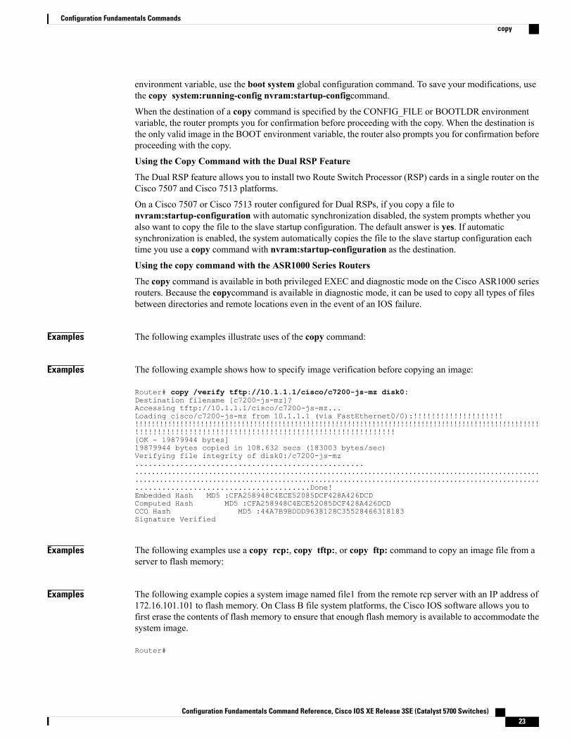
Examples The following example shows how to specify image verification before copying an image:
Router# copy /verify tftp://10.1.1.1/cisco/c7200-js-mz disk0:Destination filename [c7200-js-mz]?Accessing tftp://10.1.1.1/cisco/c7200-js-mz...Loading cisco/c7200-js-mz from 10.1.1.1 (via FastEthernet0/0):!!!!!!!!!!!!!!!!!!!!!!!!!!!!!!!!!!!!!!!!!!!!!!!!!!!!!!!!!!!!!!!!!!!!!!!!!!!!!!!!!!!!!!!!!!!!!!!!!!!!!!!!!!!!!!!!!!!!!!!!!!!!!!!!!!!!!!!!!!!!!!!!!!!!!!!!!!!!!!!!!!!!!!!!!!!!!!!!![OK - 19879944 bytes]19879944 bytes copied in 108.632 secs (183003 bytes/sec)Verifying file integrity of disk0:/c7200-js-mz................................................................................................................................................................................................................................................................................................Done!Embedded Hash MD5 :CFA258948C4ECE52085DCF428A426DCDComputed Hash MD5 :CFA258948C4ECE52085DCF428A426DCDCCO Hash MD5 :44A7B9BDDD9638128C35528466318183Signature Verified
Examples The following examples use a copy rcp:, copy tftp:, or copy ftp: command to copy an image file from aserver to flash memory:
Examples The following example copies a system image named file1 from the remote rcp server with an IP address of172.16.101.101 to flash memory. On Class B file system platforms, the Cisco IOS software allows you tofirst erase the contents of flash memory to ensure that enough flash memory is available to accommodate thesystem image.
Router#
Configuration Fundamentals Command Reference, Cisco IOS XE Release 3SE (Catalyst 5700 Switches) 23
Configuration Fundamentals Commandscopy
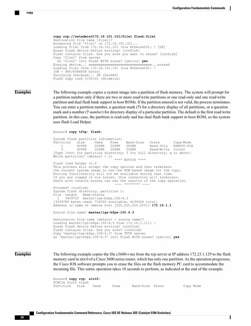
copy rcp://[email protected]/file1 flash:file1Destination file name [file1]?Accessing file 'file1' on 172.16.101.101...Loading file1 from 172.16.101.101 (via Ethernet0): ! [OK]Erase flash device before writing? [confirm]Flash contains files. Are you sure you want to erase? [confirm]Copy 'file1' from serveras 'file1' into Flash WITH erase? [yes/no] yes
Erasing device... eeeeeeeeeeeeeeeeeeeeeeeeeeeeeeee...erasedLoading file1 from 172.16.101.101 (via Ethernet0): ![OK - 984/8388608 bytes]Verifying checksum... OK (0x14B3)Flash copy took 0:00:01 [hh:mm:ss]
Examples The following example copies a system image into a partition of flash memory. The system will prompt fora partition number only if there are two or more read/write partitions or one read-only and one read/writepartition and dual flash bank support in boot ROMs. If the partition entered is not valid, the process terminates.You can enter a partition number, a question mark (?) for a directory display of all partitions, or a questionmark and a number (? number) for directory display of a particular partition. The default is the first read/writepartition. In this case, the partition is read-only and has dual flash bank support in boot ROM, so the systemuses flash Load Helper.
Router# copy tftp: flash:
System flash partition information:Partition Size Used Free Bank-Size State Copy-Mode
1 4096K 2048K 2048K 2048K Read Only RXBOOT-FLH2 4096K 2048K 2048K 2048K Read/Write Direct
[Type ?<no> for partition directory; ? for full directory; q to abort]Which partition? [default = 2]
**** NOTICE ****Flash load helper v1.0This process will accept the copy options and then terminatethe current system image to use the ROM based image for the copy.Routing functionality will not be available during that time.If you are logged in via telnet, this connection will terminate.Users with console access can see the results of the copy operation.
---- ******** ----Proceed? [confirm]System flash directory, partition 1:File Length Name/status1 3459720 master/igs-bfpx.100-4.3
[3459784 bytes used, 734520 available, 4194304 total]Address or name of remote host [255.255.255.255]? 172.16.1.1
Source file name? master/igs-bfpx-100.4.3
Destination file name [default = source name]?Loading master/igs-bfpx.100-4.3 from 172.16.1.111: !Erase flash device before writing? [confirm]Flash contains files. Are you sure? [confirm]Copy 'master/igs-bfpx.100-4.3' from TFTP serveras 'master/igs-bfpx.100-4.3' into Flash WITH erase? [yes/no] yes
Examples The following example copies the file c3600-i-mz from the rcp server at IP address 172.23.1.129 to the flashmemory card in slot 0 of a Cisco 3600 series router, which has only one partition. As the operation progresses,the Cisco IOS software prompts you to erase the files on the flash memory PC card to accommodate theincoming file. This entire operation takes 18 seconds to perform, as indicated at the end of the example.
Router# copy rcp: slot0:PCMCIA Slot0 flashPartition Size Used Free Bank-Size State Copy Mode
Configuration Fundamentals Command Reference, Cisco IOS XE Release 3SE (Catalyst 5700 Switches)24
Configuration Fundamentals Commandscopy
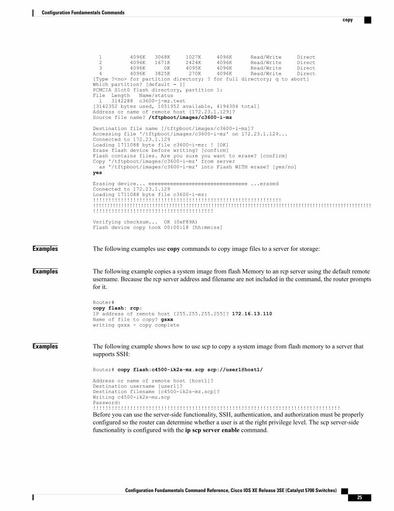
1 4096K 3068K 1027K 4096K Read/Write Direct2 4096K 1671K 2424K 4096K Read/Write Direct3 4096K 0K 4095K 4096K Read/Write Direct4 4096K 3825K 270K 4096K Read/Write Direct
[Type ?<no> for partition directory; ? for full directory; q to abort]Which partition? [default = 1]PCMCIA Slot0 flash directory, partition 1:File Length Name/status1 3142288 c3600-j-mz.test
[3142352 bytes used, 1051952 available, 4194304 total]Address or name of remote host [172.23.1.129]?Source file name? /tftpboot/images/c3600-i-mz
Destination file name [/tftpboot/images/c3600-i-mz]?Accessing file '/tftpboot/images/c3600-i-mz' on 172.23.1.129...Connected to 172.23.1.129Loading 1711088 byte file c3600-i-mz: ! [OK]Erase flash device before writing? [confirm]Flash contains files. Are you sure you want to erase? [confirm]Copy '/tftpboot/images/c3600-i-mz' from serveras '/tftpboot/images/c3600-i-mz' into Flash WITH erase? [yes/no]
yes
Erasing device... eeeeeeeeeeeeeeeeeeeeeeeeeeeeeeee ...erasedConnected to 172.23.1.129Loading 1711088 byte file c3600-i-mz:!!!!!!!!!!!!!!!!!!!!!!!!!!!!!!!!!!!!!!!!!!!!!!!!!!!!!!!!!!!!!!!!!!!!!!!!!!!!!!!!!!!!!!!!!!!!!!!!!!!!!!!!!!!!!!!!!!!!!!!!!!!!!!!!!!!!!!!!!!!!!!!!!!!!!!!!!!!!!!!!!!!!!!!!!!!!!!!!!!!!!!!!!!!!!!!!!!!!!!!
Verifying checksum... OK (0xF89A)Flash device copy took 00:00:18 [hh:mm:ss]
Examples The following examples use copy commands to copy image files to a server for storage:
Examples The following example copies a system image from flash Memory to an rcp server using the default remoteusername. Because the rcp server address and filename are not included in the command, the router promptsfor it.
Router#copy flash: rcp:IP address of remote host [255.255.255.255]? 172.16.13.110Name of file to copy? gsxxwriting gsxx - copy complete
Examples The following example shows how to use scp to copy a system image from flash memory to a server thatsupports SSH:
Router# copy flash:c4500-ik2s-mz.scp scp://user1@host1/
Address or name of remote host [host1]?Destination username [user1]?Destination filename [c4500-ik2s-mz.scp]?Writing c4500-ik2s-mz.scpPassword:!!!!!!!!!!!!!!!!!!!!!!!!!!!!!!!!!!!!!!!!!!!!!!!!!!!!!!!!!!!!!!!!!!!!!!!!!!!!!!!!Before you can use the server-side functionality, SSH, authentication, and authorization must be properlyconfigured so the router can determine whether a user is at the right privilege level. The scp server-sidefunctionality is configured with the ip scp server enable command.
Configuration Fundamentals Command Reference, Cisco IOS XE Release 3SE (Catalyst 5700 Switches) 25
Configuration Fundamentals Commandscopy
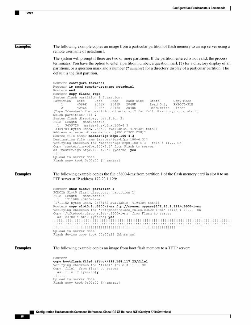
Examples The following example copies an image from a particular partition of flash memory to an rcp server using aremote username of netadmin1.
The system will prompt if there are two or more partitions. If the partition entered is not valid, the processterminates. You have the option to enter a partition number, a question mark (?) for a directory display of allpartitions, or a question mark and a number (? number) for a directory display of a particular partition. Thedefault is the first partition.
Router# configure terminalRouter# ip rcmd remote-username netadmin1Router# endRouter# copy flash: rcp:System flash partition information:Partition Size Used Free Bank-Size State Copy-Mode
1 4096K 2048K 2048K 2048K Read Only RXBOOT-FLH2 4096K 2048K 2048K 2048K Read/Write Direct
[Type ?<number> for partition directory; ? for full directory; q to abort]Which partition? [1] 2System flash directory, partition 2:File Length Name/status1 3459720 master/igs-bfpx.100-4.3
[3459784 bytes used, 734520 available, 4194304 total]Address or name of remote host [ABC.CISCO.COM]?Source file name? master/igs-bfpx.100-4.3Destination file name [master/igs-bfpx.100-4.3]?Verifying checksum for 'master/igs-bfpx.100-4.3' (file # 1)... OKCopy 'master/igs-bfpx.100-4.3' from Flash to serveras 'master/igs-bfpx.100-4.3'? [yes/no] yes!!!!...Upload to server doneFlash copy took 0:00:00 [hh:mm:ss]
Examples The following example copies the file c3600-i-mz from partition 1 of the flash memory card in slot 0 to anFTP server at IP address 172.23.1.129:
Router# show slot0: partition 1PCMCIA Slot0 flash directory, partition 1:File Length Name/status1 1711088 c3600-i-mz
[1711152 bytes used, 2483152 available, 4194304 total]Router# copy slot0:1:c3600-i-mz ftp://myuser:[email protected]/c3600-i-mzVerifying checksum for '/tftpboot/cisco_rules/c3600-i-mz' (file # 1)... OKCopy '/tftpboot/cisco_rules/c3600-i-mz' from Flash to serveras 'c3700-i-mz'? [yes/no] yes
!!!!!!!!!!!!!!!!!!!!!!!!!!!!!!!!!!!!!!!!!!!!!!!!!!!!!!!!!!!!!!!!!!!!!!!!!!!!!!!!!!!!!!!!!!!!!!!!!!!!!!!!!!!!!!!!!!!!!!!!!!!!!!!!!!!!!!!!!!!!!!!!!!!!!!!!!!!!!!!!!!!!!!!!!!!!!!!!!!!!!!!!!!!!!!!!!!!!!!!!!!!!!!!!!!!!!!!!!!!!!!!!!!!!!!!!!!!!!!!!!!!!!!!!!!!!!!!!!!!!Upload to server doneFlash device copy took 00:00:23 [hh:mm:ss]
Examples The following example copies an image from boot flash memory to a TFTP server:
Router#copy bootflash:file1 tftp://192.168.117.23/file1Verifying checksum for 'file1' (file # 1)... OKCopy 'file1' from Flash to serveras 'file1'? [yes/no]y
!!!!...Upload to server doneFlash copy took 0:00:00 [hh:mm:ss]
Configuration Fundamentals Command Reference, Cisco IOS XE Release 3SE (Catalyst 5700 Switches)26
Configuration Fundamentals Commandscopy
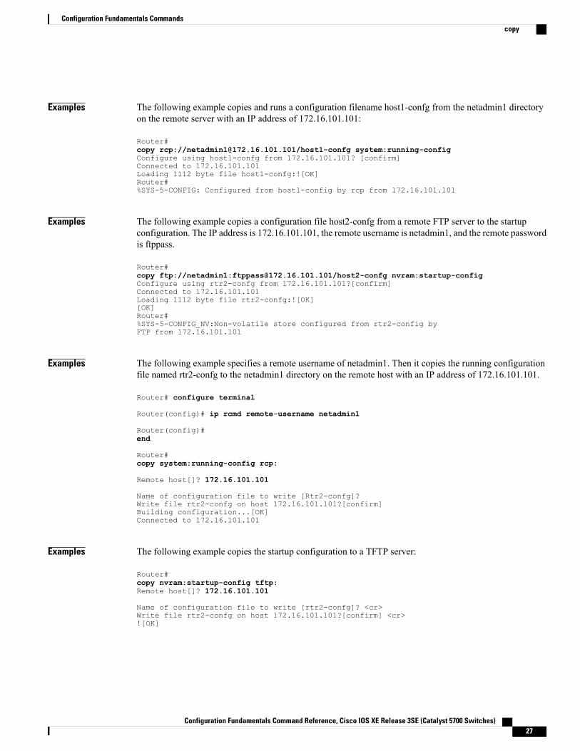
Examples The following example copies and runs a configuration filename host1-confg from the netadmin1 directoryon the remote server with an IP address of 172.16.101.101:
Router#copy rcp://[email protected]/host1-confg system:running-configConfigure using host1-confg from 172.16.101.101? [confirm]Connected to 172.16.101.101Loading 1112 byte file host1-confg:![OK]Router#%SYS-5-CONFIG: Configured from host1-config by rcp from 172.16.101.101
Examples The following example copies a configuration file host2-confg from a remote FTP server to the startupconfiguration. The IP address is 172.16.101.101, the remote username is netadmin1, and the remote passwordis ftppass.
Router#copy ftp://netadmin1:[email protected]/host2-confg nvram:startup-configConfigure using rtr2-confg from 172.16.101.101?[confirm]Connected to 172.16.101.101Loading 1112 byte file rtr2-confg:![OK][OK]Router#%SYS-5-CONFIG_NV:Non-volatile store configured from rtr2-config byFTP from 172.16.101.101
Examples The following example specifies a remote username of netadmin1. Then it copies the running configurationfile named rtr2-confg to the netadmin1 directory on the remote host with an IP address of 172.16.101.101.
Router# configure terminal
Router(config)# ip rcmd remote-username netadmin1
Router(config)#end
Router#copy system:running-config rcp:
Remote host[]? 172.16.101.101
Name of configuration file to write [Rtr2-confg]?Write file rtr2-confg on host 172.16.101.101?[confirm]Building configuration...[OK]Connected to 172.16.101.101
Examples The following example copies the startup configuration to a TFTP server:
Router#copy nvram:startup-config tftp:Remote host[]? 172.16.101.101
Name of configuration file to write [rtr2-confg]? <cr>Write file rtr2-confg on host 172.16.101.101?[confirm] <cr>![OK]
Configuration Fundamentals Command Reference, Cisco IOS XE Release 3SE (Catalyst 5700 Switches) 27
Configuration Fundamentals Commandscopy
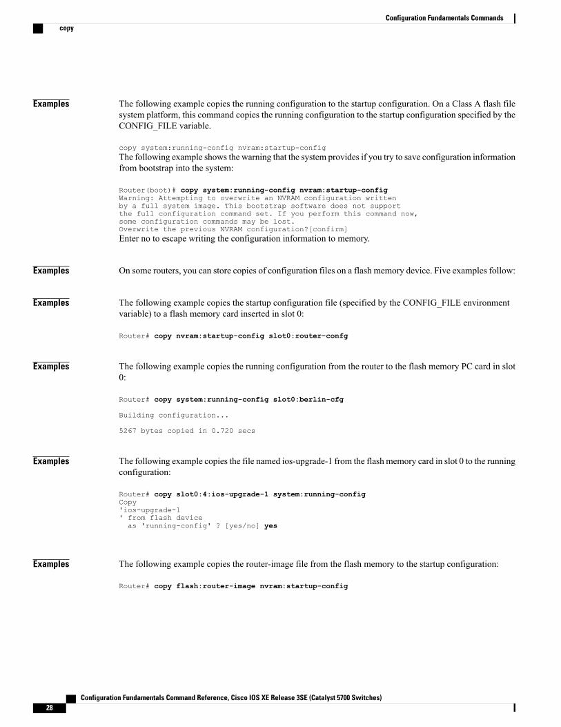
Examples The following example copies the running configuration to the startup configuration. On a Class A flash filesystem platform, this command copies the running configuration to the startup configuration specified by theCONFIG_FILE variable.
copy system:running-config nvram:startup-configThe following example shows the warning that the system provides if you try to save configuration informationfrom bootstrap into the system:
Router(boot)# copy system:running-config nvram:startup-configWarning: Attempting to overwrite an NVRAM configuration writtenby a full system image. This bootstrap software does not supportthe full configuration command set. If you perform this command now,some configuration commands may be lost.Overwrite the previous NVRAM configuration?[confirm]Enter no to escape writing the configuration information to memory.
Examples On some routers, you can store copies of configuration files on a flash memory device. Five examples follow:
Examples The following example copies the startup configuration file (specified by the CONFIG_FILE environmentvariable) to a flash memory card inserted in slot 0:
Router# copy nvram:startup-config slot0:router-confg
Examples The following example copies the running configuration from the router to the flash memory PC card in slot0:
Router# copy system:running-config slot0:berlin-cfg
Building configuration...
5267 bytes copied in 0.720 secs
Examples The following example copies the file named ios-upgrade-1 from the flash memory card in slot 0 to the runningconfiguration:
Router# copy slot0:4:ios-upgrade-1 system:running-configCopy'ios-upgrade-1' from flash deviceas 'running-config' ? [yes/no] yes
Examples The following example copies the router-image file from the flash memory to the startup configuration:
Router# copy flash:router-image nvram:startup-config
Configuration Fundamentals Command Reference, Cisco IOS XE Release 3SE (Catalyst 5700 Switches)28
Configuration Fundamentals Commandscopy
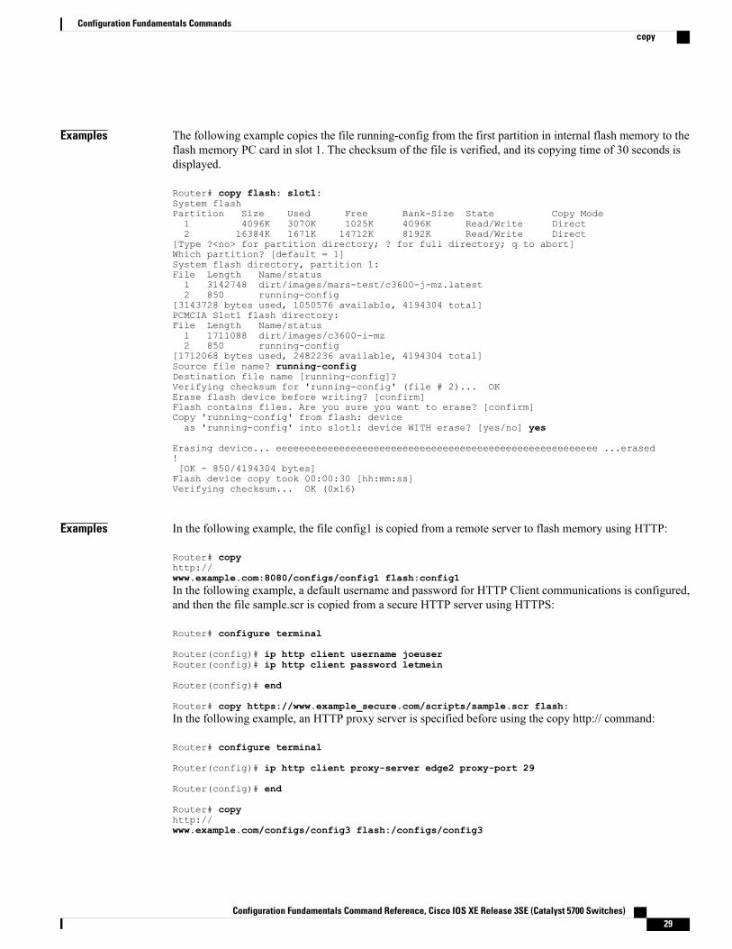
Examples The following example copies the file running-config from the first partition in internal flash memory to theflash memory PC card in slot 1. The checksum of the file is verified, and its copying time of 30 seconds isdisplayed.
Router# copy flash: slot1:System flashPartition Size Used Free Bank-Size State Copy Mode1 4096K 3070K 1025K 4096K Read/Write Direct2 16384K 1671K 14712K 8192K Read/Write Direct
[Type ?<no> for partition directory; ? for full directory; q to abort]Which partition? [default = 1]System flash directory, partition 1:File Length Name/status1 3142748 dirt/images/mars-test/c3600-j-mz.latest2 850 running-config
[3143728 bytes used, 1050576 available, 4194304 total]PCMCIA Slot1 flash directory:File Length Name/status1 1711088 dirt/images/c3600-i-mz2 850 running-config
[1712068 bytes used, 2482236 available, 4194304 total]Source file name? running-configDestination file name [running-config]?Verifying checksum for 'running-config' (file # 2)... OKErase flash device before writing? [confirm]Flash contains files. Are you sure you want to erase? [confirm]Copy 'running-config' from flash: deviceas 'running-config' into slot1: device WITH erase? [yes/no] yes
Erasing device... eeeeeeeeeeeeeeeeeeeeeeeeeeeeeeeeeeeeeeeeeeeeeeeeeeeeeeee ...erased![OK - 850/4194304 bytes]Flash device copy took 00:00:30 [hh:mm:ss]Verifying checksum... OK (0x16)
Examples In the following example, the file config1 is copied from a remote server to flash memory using HTTP:
Router# copyhttp://www.example.com:8080/configs/config1 flash:config1In the following example, a default username and password for HTTP Client communications is configured,and then the file sample.scr is copied from a secure HTTP server using HTTPS:
Router# configure terminal
Router(config)# ip http client username joeuserRouter(config)# ip http client password letmein
Router(config)# end
Router# copy https://www.example_secure.com/scripts/sample.scr flash:In the following example, an HTTP proxy server is specified before using the copy http:// command:
Router# configure terminal
Router(config)# ip http client proxy-server edge2 proxy-port 29
Router(config)# end
Router# copyhttp://www.example.com/configs/config3 flash:/configs/config3
Configuration Fundamentals Command Reference, Cisco IOS XE Release 3SE (Catalyst 5700 Switches) 29
Configuration Fundamentals Commandscopy
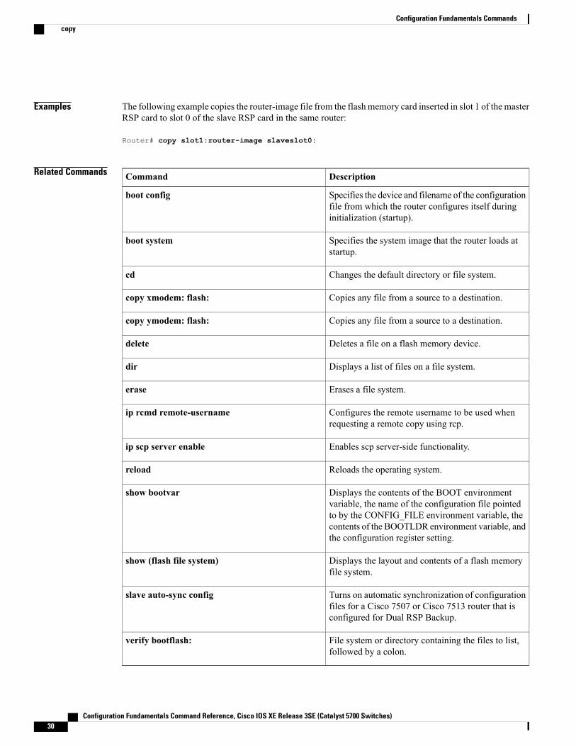
Examples The following example copies the router-image file from the flash memory card inserted in slot 1 of the masterRSP card to slot 0 of the slave RSP card in the same router:
Router# copy slot1:router-image slaveslot0:
Related Commands DescriptionCommand
Specifies the device and filename of the configurationfile from which the router configures itself duringinitialization (startup).
boot config
Specifies the system image that the router loads atstartup.
boot system
Changes the default directory or file system.cd
Copies any file from a source to a destination.copy xmodem: flash:
Copies any file from a source to a destination.copy ymodem: flash:
Deletes a file on a flash memory device.delete
Displays a list of files on a file system.dir
Erases a file system.erase
Configures the remote username to be used whenrequesting a remote copy using rcp.
ip rcmd remote-username
Enables scp server-side functionality.ip scp server enable
Reloads the operating system.reload
Displays the contents of the BOOT environmentvariable, the name of the configuration file pointedto by the CONFIG_FILE environment variable, thecontents of the BOOTLDR environment variable, andthe configuration register setting.
show bootvar
Displays the layout and contents of a flash memoryfile system.
show (flash file system)
Turns on automatic synchronization of configurationfiles for a Cisco 7507 or Cisco 7513 router that isconfigured for Dual RSP Backup.
slave auto-sync config
File system or directory containing the files to list,followed by a colon.
verify bootflash:
Configuration Fundamentals Command Reference, Cisco IOS XE Release 3SE (Catalyst 5700 Switches)30
Configuration Fundamentals Commandscopy

Configuration Fundamentals Command Reference, Cisco IOS XE Release 3SE (Catalyst 5700 Switches) 31
Configuration Fundamentals Commandscopy
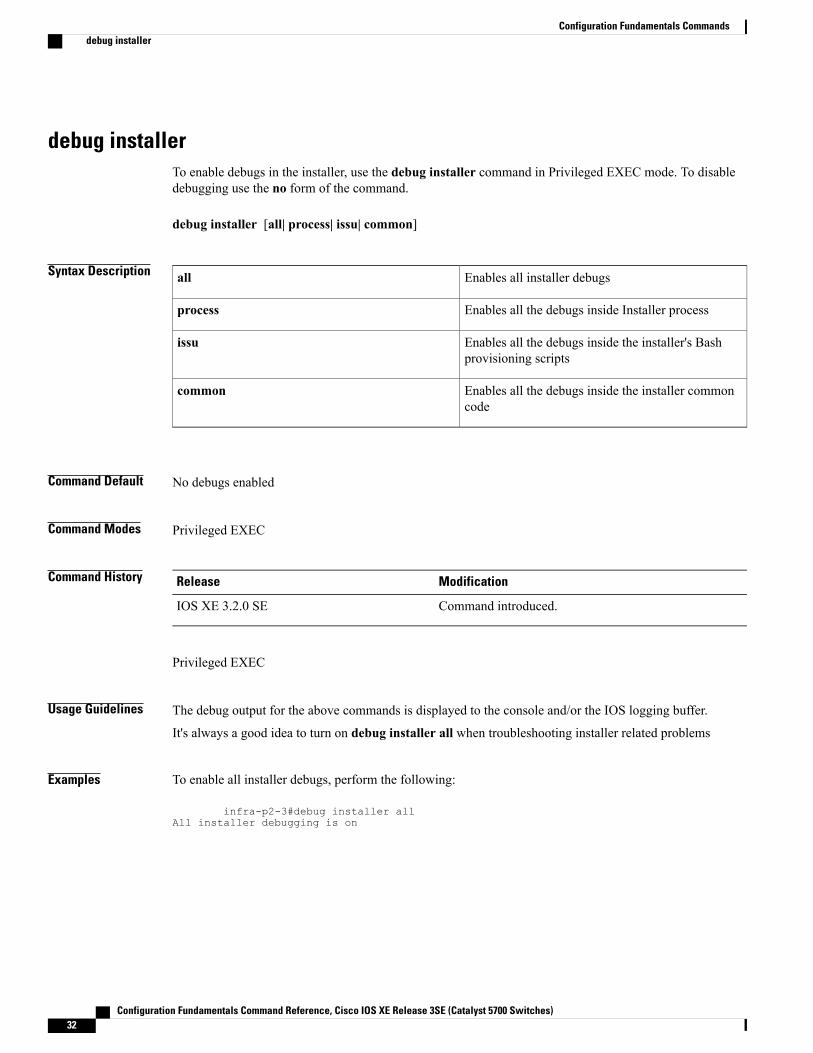
debug installerTo enable debugs in the installer, use the debug installer command in Privileged EXEC mode. To disabledebugging use the no form of the command.
debug installer [all| process| issu| common]
Syntax Description Enables all installer debugsall
Enables all the debugs inside Installer processprocess
Enables all the debugs inside the installer's Bashprovisioning scripts
issu
Enables all the debugs inside the installer commoncode
common
Command Default No debugs enabled
Command Modes Privileged EXEC
Command History ModificationRelease
Command introduced.IOS XE 3.2.0 SE
Privileged EXEC
Usage Guidelines The debug output for the above commands is displayed to the console and/or the IOS logging buffer.
It's always a good idea to turn on debug installer all when troubleshooting installer related problems
Examples To enable all installer debugs, perform the following:
infra-p2-3#debug installer allAll installer debugging is on
Configuration Fundamentals Command Reference, Cisco IOS XE Release 3SE (Catalyst 5700 Switches)32
Configuration Fundamentals Commandsdebug installer
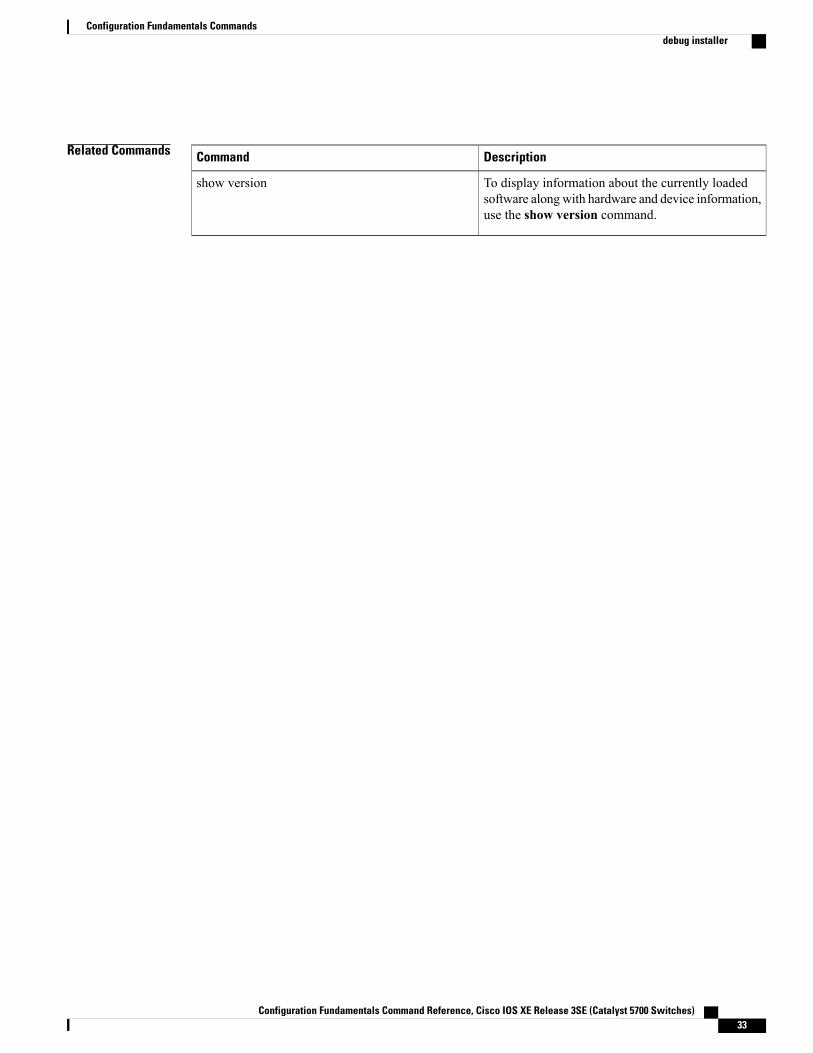
Related Commands DescriptionCommand
To display information about the currently loadedsoftware alongwith hardware and device information,use the show version command.
show version
Configuration Fundamentals Command Reference, Cisco IOS XE Release 3SE (Catalyst 5700 Switches) 33
Configuration Fundamentals Commandsdebug installer
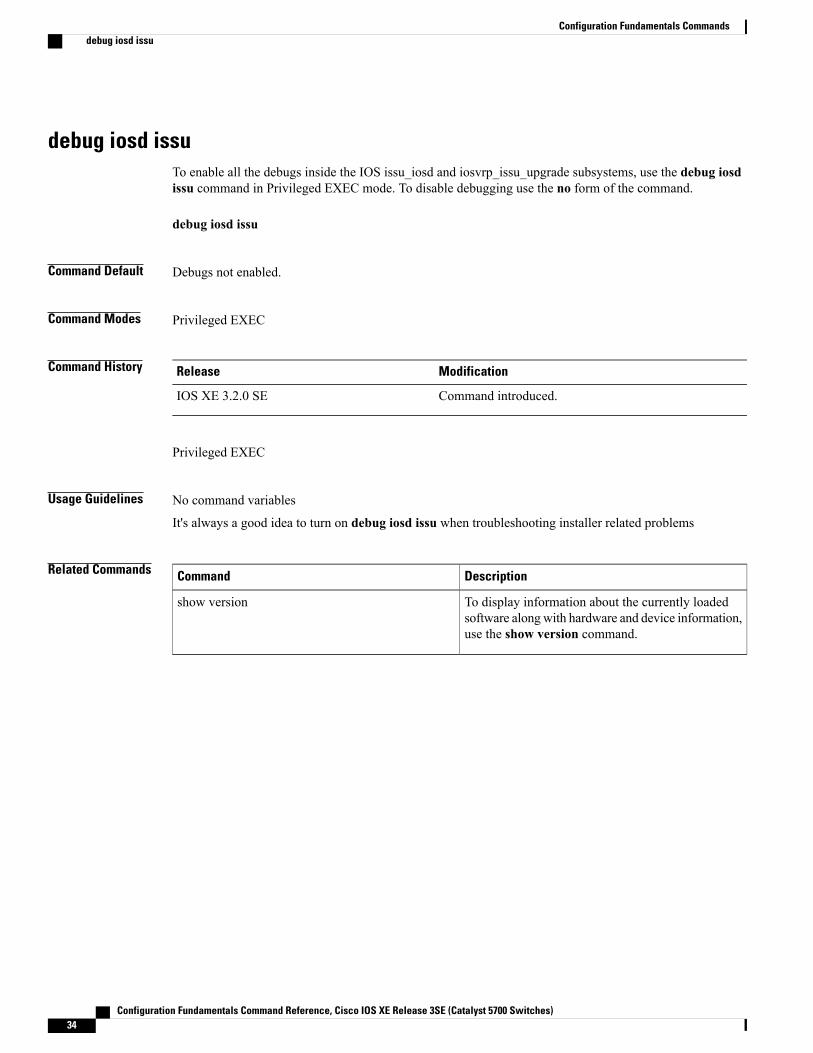
debug iosd issuTo enable all the debugs inside the IOS issu_iosd and iosvrp_issu_upgrade subsystems, use the debug iosdissu command in Privileged EXEC mode. To disable debugging use the no form of the command.
debug iosd issu
Command Default Debugs not enabled.
Command Modes Privileged EXEC
Command History ModificationRelease
Command introduced.IOS XE 3.2.0 SE
Privileged EXEC
Usage Guidelines No command variables
It's always a good idea to turn on debug iosd issu when troubleshooting installer related problems
Related Commands DescriptionCommand
To display information about the currently loadedsoftware alongwith hardware and device information,use the show version command.
show version
Configuration Fundamentals Command Reference, Cisco IOS XE Release 3SE (Catalyst 5700 Switches)34
Configuration Fundamentals Commandsdebug iosd issu
define interface-rangeTo create an interface-range macro, use the define interface-range command in global configuration mode.To remove an interface-range macro, use the no form of this command.
define interface-range macro-name interface-range
Syntax Description Name of the interface-range macro.macro-name
Type of interface range.
• For a list of valid values, see the “UsageGuidelines” section.
interface-range
Command Default Interface-range macro is not configured.
Command Modes Global configuration (config)
Command History ModificationRelease
This command was introduced.12.2(14)SX
This commandwas integrated into Cisco IOSXERelease 12.2(17d)SXB.12.2(17d)SXB
This command was integrated into Cisco IOS Release 12.2(33)SRA.12.2(33)SRA
This command was implemented on the Cisco ASR 901 SeriesAggregation Services Routers.
15.1(2)SNG
Usage Guidelines• The define interface-range command applies a particular configuration on multiple interfaces andcreates multiple logical, and sub interfaces.
• An interface range macro name can comprise up to 32 characters.
• An interface range for a macro can accept a maximum of five ranges. However, the subinterface rangefor a macro accepts only one range.
• An interface range cannot span slots.
• Use the interface-type slot/first-interface last-interface format to enter the interface range.
• Valid values for the interface-type argument are as follows:
Configuration Fundamentals Command Reference, Cisco IOS XE Release 3SE (Catalyst 5700 Switches) 35
Configuration Fundamentals Commandsdefine interface-range
atm—Supported on Cisco 7600 series routers that are configured with a Supervisor Engine 2•
• ethernet
• fastethernet
• ge-wan—Supported on Cisco 7600 series routers that are configured with a Supervisor Engine 2
• gigabitethernet
• loopback
• port-channel interface-number—Valid values are from 1 to 256
• pos—Supported on Cisco 7600 series routers that are configured with a Supervisor Engine 2
• tengigabitethernet
• tunnel
• vlan vlan-id—Valid values are from 1 to 4094
Examples The following example shows how to create a multiple-interface macro:Device(config)# define interface-range macro1 ethernet 1/2 - 5, fastethernet 5/5 - 10The following example shows how to create multiple loopback interfaces:Device(config)# define interface-range loopback1-10
Related Commands DescriptionCommand
Executes a command on multiple ports at the sametime.
interface range
Configuration Fundamentals Command Reference, Cisco IOS XE Release 3SE (Catalyst 5700 Switches)36
Configuration Fundamentals Commandsdefine interface-range
enableTo change the privilege level for a CLI session or to use a CLI view for a CLI session, use the enable commandin either user EXEC, privileged EXEC, or diagnostic mode.
enable [privilege-level] [view [ view-name ]]
Syntax Description (Optional) Privilege level at which to log in.privilege-level
(Optional) Enters into root view, which enables usersto configure CLI views.
This keyword is required if you want toconfigure a CLI view.
Note
view
(Optional) Enters or exits a specified command-lineinterface (CLI) view. This keyword can be used toswitch from one CLI view to another CLI view.
view-name
Command Default Privilege-level 15 (privileged EXEC)
Command Modes User EXEC (>)
Privileged EXEC (#)
Diagnostic Mode (diag)
Command History ModificationRelease
This command was introduced.10.0
The view keyword and view-name argument were added.12.3(7)T
This command was integrated into Cisco IOS Release 12.2(33)SRA.12.2(33)SRA
The view keyword and view-name argument were integrated into Cisco IOSRelease 12.2(33)SRB.
12.2(33)SRB
This command is supported in the Cisco IOS Release 12.2SX train. Supportin a specific 12.2SX release of this train depends on your feature set, platform,and platform hardware.
12.2SX
This command was integrated into Cisco IOS Release 12.2(22)SB.12.2(33)SB
This command became available on the ASR 1000 Series Routers, andbecame available in diagnostic mode for the first time.
Cisco IOS XE Release 2.1
Configuration Fundamentals Command Reference, Cisco IOS XE Release 3SE (Catalyst 5700 Switches) 37
Configuration Fundamentals Commandsenable
Usage Guidelines By default, using the enable command without the privilege-level argument in user EXEC mode causes therouter to enter privileged EXEC mode (privilege-level 15).
Entering privileged EXEC mode enables the use of privileged commands. Because many of the privilegedcommands set operating parameters, privileged access should be password-protected to prevent unauthorizeduse. If the system administrator has set a password with the enable password global configuration command,you are prompted to enter the password before being allowed access to privileged EXECmode. The passwordis case sensitive.
If an enable password has not been set, only enable mode can be accessed through the console connection.
Security levels can be set by an administrator using the enable password and privilege level commands. Upto 16 privilege levels can be specified, using the numbers 0 through 15. Using these privilege levels, theadministrator can allow or deny access to specific commands. Privilege level 0 is associated with user EXECmode, and privilege level 15 is associated with privileged EXEC mode.
For more information on defined privilege levels, see the Cisco IOSSecurity Configuration Guide and theCisco IOS Security Command Reference publications.
If a level is not specified when entering the enable command, the user will enter the default mode of privilegedEXEC (level 15).
Accessing a CLI View
CLI views restrict user access to specified CLI and configuration information. To configure and access CLIviews, users must first enter into root view, which is accomplished via the enable view command (withoutthe view-name argument). Thereafter, users are prompted for a password, which is the same password as theprivilege level 15 password.
The view-name argument is used to switch from one view to another view.
To prevent dictionary attacks, a user is prompted for a password even if an incorrect view name is given. Theuser is denied access only after an incorrect view name and password are given.
Examples In the following example, the user enters privileged EXEC mode (changes to privilege-level 15) by using theenable command without a privilege-level argument. The system prompts the user for a password beforeallowing access to the privileged EXEC mode. The password is not printed to the screen. The user then exitsback to user EXECmode using the disable command. Note that the prompt for user EXECmode is the greaterthan symbol (>), and the prompt for privileged EXEC mode is the number sign (#).
Router> enablePassword: <letmein>Router# disableRouter>The following example shows which commands are available inside the CLI view “first” after the user haslogged into this view:
Router# enable view firstPassword:00:28:23:%PARSER-6-VIEW_SWITCH:successfully set to view 'first'.Router# ?Exec commands:configure Enter configuration modeenable Turn on privileged commandsexit Exit from the EXECshow Show running system information
Configuration Fundamentals Command Reference, Cisco IOS XE Release 3SE (Catalyst 5700 Switches)38
Configuration Fundamentals Commandsenable
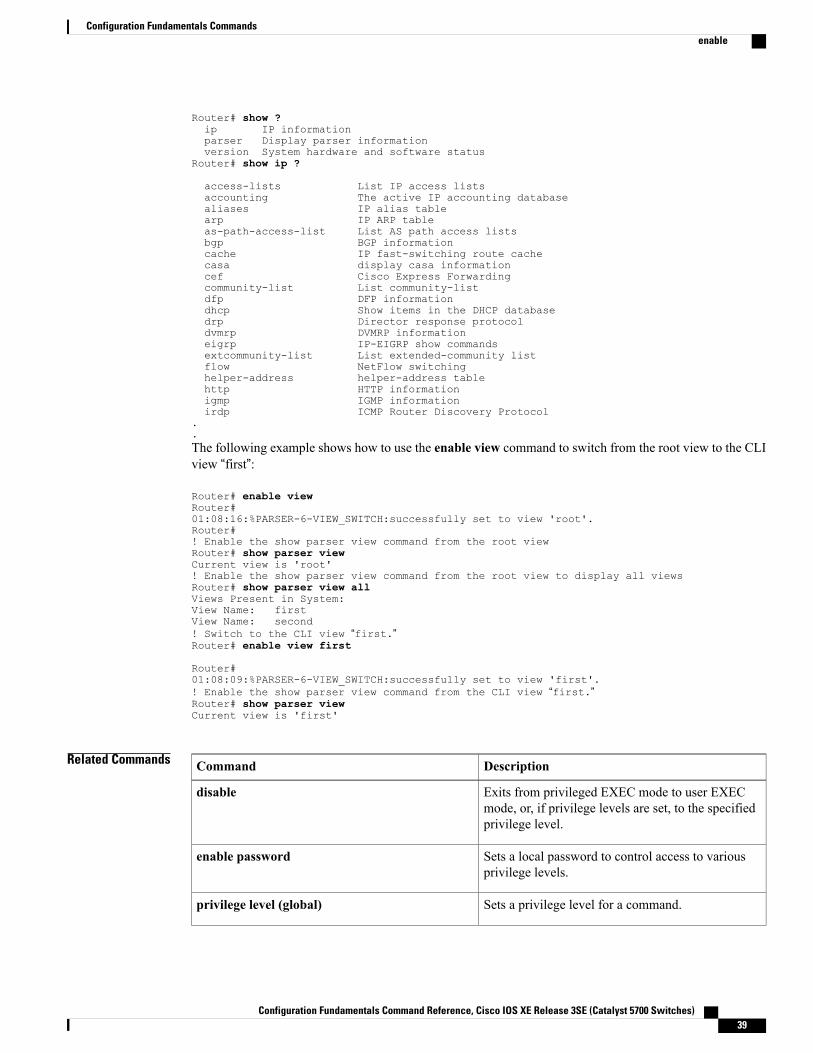
Router# show ?ip IP informationparser Display parser informationversion System hardware and software status
Router# show ip ?
access-lists List IP access listsaccounting The active IP accounting databasealiases IP alias tablearp IP ARP tableas-path-access-list List AS path access listsbgp BGP informationcache IP fast-switching route cachecasa display casa informationcef Cisco Express Forwardingcommunity-list List community-listdfp DFP informationdhcp Show items in the DHCP databasedrp Director response protocoldvmrp DVMRP informationeigrp IP-EIGRP show commandsextcommunity-list List extended-community listflow NetFlow switchinghelper-address helper-address tablehttp HTTP informationigmp IGMP informationirdp ICMP Router Discovery Protocol
.
.The following example shows how to use the enable view command to switch from the root view to the CLIview “first”:
Router# enable viewRouter#01:08:16:%PARSER-6-VIEW_SWITCH:successfully set to view 'root'.Router#! Enable the show parser view command from the root viewRouter# show parser viewCurrent view is 'root'! Enable the show parser view command from the root view to display all viewsRouter# show parser view allViews Present in System:View Name: firstView Name: second! Switch to the CLI view “first.”Router# enable view first
Router#01:08:09:%PARSER-6-VIEW_SWITCH:successfully set to view 'first'.! Enable the show parser view command from the CLI view “first.”Router# show parser viewCurrent view is 'first'
Related Commands DescriptionCommand
Exits from privileged EXEC mode to user EXECmode, or, if privilege levels are set, to the specifiedprivilege level.
disable
Sets a local password to control access to variousprivilege levels.
enable password
Sets a privilege level for a command.privilege level (global)
Configuration Fundamentals Command Reference, Cisco IOS XE Release 3SE (Catalyst 5700 Switches) 39
Configuration Fundamentals Commandsenable
DescriptionCommand
Sets a privilege level for a command for a specificline.
privilege level (line)
Configuration Fundamentals Command Reference, Cisco IOS XE Release 3SE (Catalyst 5700 Switches)40
Configuration Fundamentals Commandsenable
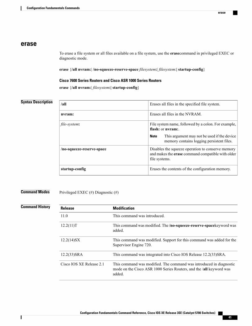
eraseTo erase a file system or all files available on a file system, use the erasecommand in privileged EXEC ordiagnostic mode.
erase {/all nvram:| /no-squeeze-reserve-space filesystem:| filesystem:| startup-config}
Cisco 7600 Series Routers and Cisco ASR 1000 Series Routers
erase {/all nvram:| filesystem:| startup-config}
Syntax Description Erases all files in the specified file system./all
Erases all files in the NVRAM.nvram:
File system name, followed by a colon. For example,flash: or nvram:.
This argument may not be used if the devicememory contains logging persistent files.
Note
file-system:
Disables the squeeze operation to conserve memoryandmakes the erase command compatible with olderfile systems.
/no-squeeze-reserve-space
Erases the contents of the configuration memory.startup-config
Command Modes Privileged EXEC (#) Diagnostic (#)
Command History ModificationRelease
This command was introduced.11.0
This command was modified. The /no-squeeze-reserve-spacekeyword wasadded.
12.2(11)T
This command was modified. Support for this command was added for theSupervisor Engine 720.
12.2(14)SX
This command was integrated into Cisco IOS Release 12.2(33)SRA.12.2(33)SRA
This command was modified. The command was introduced in diagnosticmode on the Cisco ASR 1000 Series Routers, and the /all keyword wasadded.
Cisco IOS XE Release 2.1
Configuration Fundamentals Command Reference, Cisco IOS XE Release 3SE (Catalyst 5700 Switches) 41
Configuration Fundamentals Commandserase
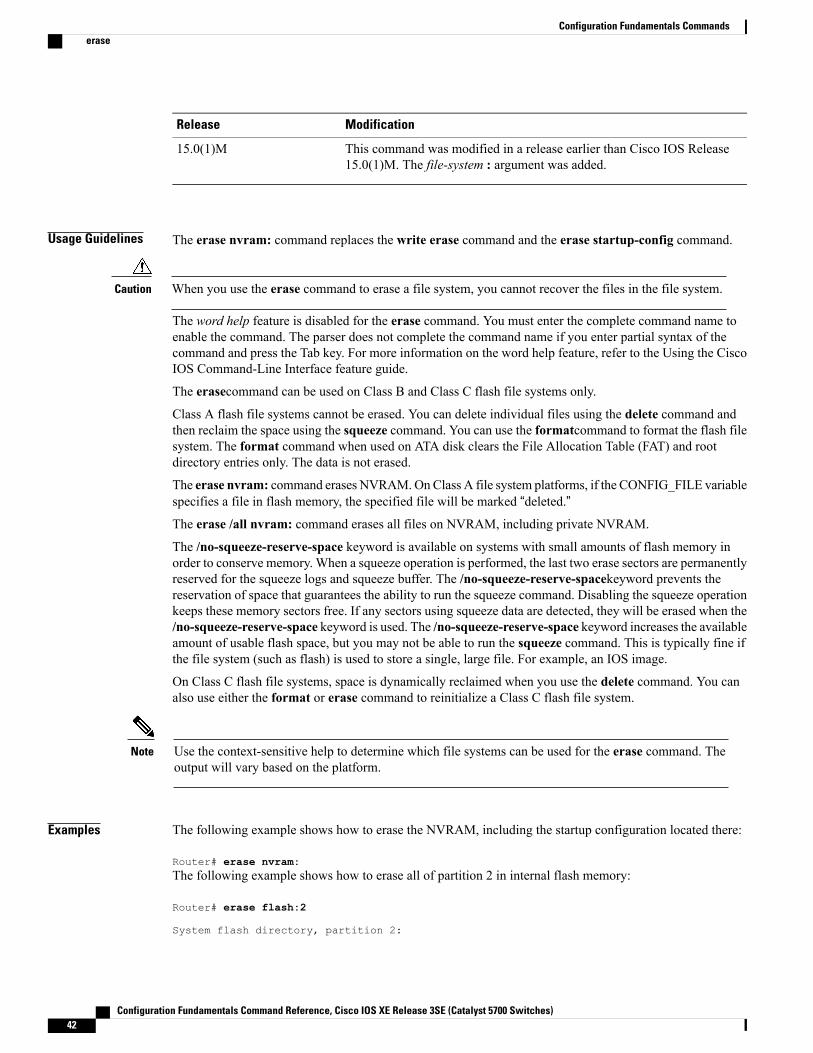
ModificationRelease
This command was modified in a release earlier than Cisco IOS Release15.0(1)M. The file-system : argument was added.
15.0(1)M
Usage Guidelines The erase nvram: command replaces the write erase command and the erase startup-config command.
When you use the erase command to erase a file system, you cannot recover the files in the file system.Caution
The word help feature is disabled for the erase command. You must enter the complete command name toenable the command. The parser does not complete the command name if you enter partial syntax of thecommand and press the Tab key. For more information on the word help feature, refer to the Using the CiscoIOS Command-Line Interface feature guide.
The erasecommand can be used on Class B and Class C flash file systems only.
Class A flash file systems cannot be erased. You can delete individual files using the delete command andthen reclaim the space using the squeeze command. You can use the formatcommand to format the flash filesystem. The format command when used on ATA disk clears the File Allocation Table (FAT) and rootdirectory entries only. The data is not erased.
The erase nvram: command erases NVRAM.OnClass A file system platforms, if the CONFIG_FILE variablespecifies a file in flash memory, the specified file will be marked “deleted.”The erase /all nvram: command erases all files on NVRAM, including private NVRAM.
The /no-squeeze-reserve-space keyword is available on systems with small amounts of flash memory inorder to conserve memory. When a squeeze operation is performed, the last two erase sectors are permanentlyreserved for the squeeze logs and squeeze buffer. The /no-squeeze-reserve-spacekeyword prevents thereservation of space that guarantees the ability to run the squeeze command. Disabling the squeeze operationkeeps these memory sectors free. If any sectors using squeeze data are detected, they will be erased when the/no-squeeze-reserve-space keyword is used. The /no-squeeze-reserve-space keyword increases the availableamount of usable flash space, but you may not be able to run the squeeze command. This is typically fine ifthe file system (such as flash) is used to store a single, large file. For example, an IOS image.
On Class C flash file systems, space is dynamically reclaimed when you use the delete command. You canalso use either the format or erase command to reinitialize a Class C flash file system.
Use the context-sensitive help to determine which file systems can be used for the erase command. Theoutput will vary based on the platform.
Note
Examples The following example shows how to erase the NVRAM, including the startup configuration located there:
Router# erase nvram:The following example shows how to erase all of partition 2 in internal flash memory:
Router# erase flash:2
System flash directory, partition 2:
Configuration Fundamentals Command Reference, Cisco IOS XE Release 3SE (Catalyst 5700 Switches)42
Configuration Fundamentals Commandserase
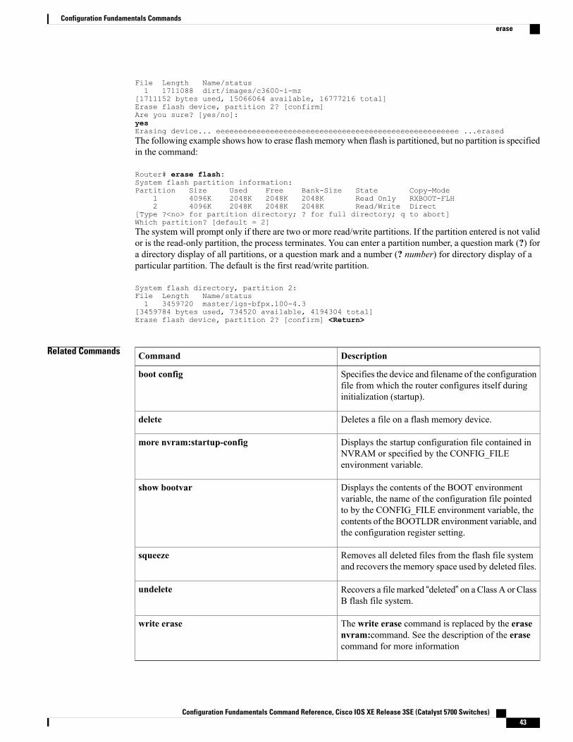
File Length Name/status1 1711088 dirt/images/c3600-i-mz
[1711152 bytes used, 15066064 available, 16777216 total]Erase flash device, partition 2? [confirm]Are you sure? [yes/no]:yesErasing device... eeeeeeeeeeeeeeeeeeeeeeeeeeeeeeeeeeeeeeeeeeeeeeeeeeeeee ...erasedThe following example shows how to erase flash memory when flash is partitioned, but no partition is specifiedin the command:
Router# erase flash:System flash partition information:Partition Size Used Free Bank-Size State Copy-Mode
1 4096K 2048K 2048K 2048K Read Only RXBOOT-FLH2 4096K 2048K 2048K 2048K Read/Write Direct
[Type ?<no> for partition directory; ? for full directory; q to abort]Which partition? [default = 2]The system will prompt only if there are two or more read/write partitions. If the partition entered is not validor is the read-only partition, the process terminates. You can enter a partition number, a question mark (?) fora directory display of all partitions, or a question mark and a number (? number) for directory display of aparticular partition. The default is the first read/write partition.
System flash directory, partition 2:File Length Name/status1 3459720 master/igs-bfpx.100-4.3
[3459784 bytes used, 734520 available, 4194304 total]Erase flash device, partition 2? [confirm] <Return>
Related Commands DescriptionCommand
Specifies the device and filename of the configurationfile from which the router configures itself duringinitialization (startup).
boot config
Deletes a file on a flash memory device.delete
Displays the startup configuration file contained inNVRAM or specified by the CONFIG_FILEenvironment variable.
more nvram:startup-config
Displays the contents of the BOOT environmentvariable, the name of the configuration file pointedto by the CONFIG_FILE environment variable, thecontents of the BOOTLDR environment variable, andthe configuration register setting.
show bootvar
Removes all deleted files from the flash file systemand recovers the memory space used by deleted files.
squeeze
Recovers a file marked “deleted” on a Class A or ClassB flash file system.
undelete
The write erase command is replaced by the erasenvram:command. See the description of the erasecommand for more information
write erase
Configuration Fundamentals Command Reference, Cisco IOS XE Release 3SE (Catalyst 5700 Switches) 43
Configuration Fundamentals Commandserase

Configuration Fundamentals Command Reference, Cisco IOS XE Release 3SE (Catalyst 5700 Switches)44
Configuration Fundamentals Commandserase
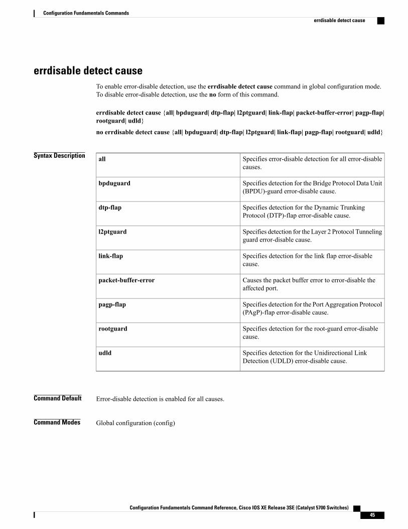
errdisable detect causeTo enable error-disable detection, use the errdisable detect cause command in global configuration mode.To disable error-disable detection, use the no form of this command.
errdisable detect cause {all| bpduguard| dtp-flap| l2ptguard| link-flap| packet-buffer-error| pagp-flap|rootguard| udld}
no errdisable detect cause {all| bpduguard| dtp-flap| l2ptguard| link-flap| pagp-flap| rootguard| udld}
Syntax Description Specifies error-disable detection for all error-disablecauses.
all
Specifies detection for the Bridge Protocol Data Unit(BPDU)-guard error-disable cause.
bpduguard
Specifies detection for the Dynamic TrunkingProtocol (DTP)-flap error-disable cause.
dtp-flap
Specifies detection for the Layer 2 Protocol Tunnelingguard error-disable cause.
l2ptguard
Specifies detection for the link flap error-disablecause.
link-flap
Causes the packet buffer error to error-disable theaffected port.
packet-buffer-error
Specifies detection for the Port Aggregation Protocol(PAgP)-flap error-disable cause.
pagp-flap
Specifies detection for the root-guard error-disablecause.
rootguard
Specifies detection for the Unidirectional LinkDetection (UDLD) error-disable cause.
udld
Command Default Error-disable detection is enabled for all causes.
Command Modes Global configuration (config)
Configuration Fundamentals Command Reference, Cisco IOS XE Release 3SE (Catalyst 5700 Switches) 45
Configuration Fundamentals Commandserrdisable detect cause
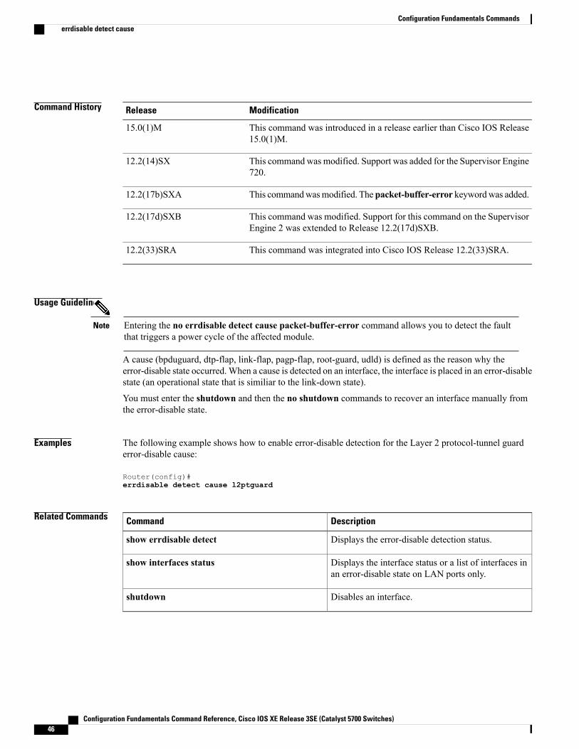
Command History ModificationRelease
This command was introduced in a release earlier than Cisco IOS Release15.0(1)M.
15.0(1)M
This command was modified. Support was added for the Supervisor Engine720.
12.2(14)SX
This commandwasmodified. The packet-buffer-error keywordwas added.12.2(17b)SXA
This command was modified. Support for this command on the SupervisorEngine 2 was extended to Release 12.2(17d)SXB.
12.2(17d)SXB
This command was integrated into Cisco IOS Release 12.2(33)SRA.12.2(33)SRA
Usage Guidelines
Entering the no errdisable detect cause packet-buffer-error command allows you to detect the faultthat triggers a power cycle of the affected module.
Note
A cause (bpduguard, dtp-flap, link-flap, pagp-flap, root-guard, udld) is defined as the reason why theerror-disable state occurred.When a cause is detected on an interface, the interface is placed in an error-disablestate (an operational state that is similiar to the link-down state).
You must enter the shutdown and then the no shutdown commands to recover an interface manually fromthe error-disable state.
Examples The following example shows how to enable error-disable detection for the Layer 2 protocol-tunnel guarderror-disable cause:
Router(config)#errdisable detect cause l2ptguard
Related Commands DescriptionCommand
Displays the error-disable detection status.show errdisable detect
Displays the interface status or a list of interfaces inan error-disable state on LAN ports only.
show interfaces status
Disables an interface.shutdown
Configuration Fundamentals Command Reference, Cisco IOS XE Release 3SE (Catalyst 5700 Switches)46
Configuration Fundamentals Commandserrdisable detect cause
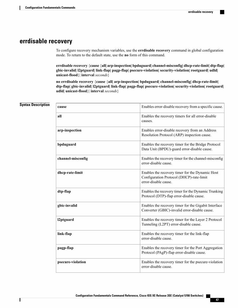
errdisable recoveryTo configure recovery mechanism variables, use the errdisable recovery command in global configurationmode. To return to the default state, use the no form of this command.
errdisable recovery {cause {all| arp-inspection| bpduguard| channel-misconfig| dhcp-rate-limit| dtp-flap|gbic-invalid| l2ptguard| link-flap| pagp-flap| psecure-violation| security-violation| rootguard| udld|unicast-flood}| interval seconds}
no errdisable recovery {cause {all| arp-inspection| bpduguard| channel-misconfig| dhcp-rate-limit|dtp-flap| gbic-invalid| l2ptguard| link-flap| pagp-flap| psecure-violation| security-violation| rootguard|udld| unicast-flood}| interval seconds}
Syntax Description Enables error-disable recovery from a specific cause.cause
Enables the recovery timers for all error-disablecauses.
all
Enables error-disable recovery from an AddressResolution Protocol (ARP) inspection cause.
arp-inspection
Enables the recovery timer for the Bridge ProtocolData Unit (BPDU)-guard error-disable cause.
bpduguard
Enables the recovery timer for the channel-misconfigerror-disable cause.
channel-misconfig
Enables the recovery timer for the Dynamic HostConfiguration Protocol (DHCP)-rate-limiterror-disable cause.
dhcp-rate-limit
Enables the recovery timer for the Dynamic TrunkingProtocol (DTP)-flap error-disable cause.
dtp-flap
Enables the recovery timer for the Gigabit InterfaceConverter (GBIC)-invalid error-disable cause.
gbic-invalid
Enables the recovery timer for the Layer 2 ProtocolTunneling (L2PT) error-disable cause.
l2ptguard
Enables the recovery timer for the link-flaperror-disable cause.
link-flap
Enables the recovery timer for the Port AggregationProtocol (PAgP)-flap error-disable cause.
pagp-flap
Enables the recovery timer for the psecure-violationerror-disable cause.
psecure-violation
Configuration Fundamentals Command Reference, Cisco IOS XE Release 3SE (Catalyst 5700 Switches) 47
Configuration Fundamentals Commandserrdisable recovery
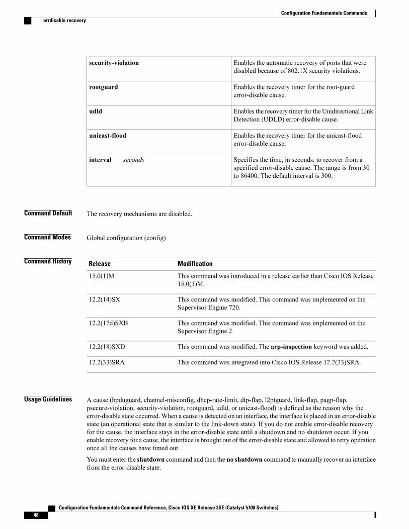
Enables the automatic recovery of ports that weredisabled because of 802.1X security violations.
security-violation
Enables the recovery timer for the root-guarderror-disable cause.
rootguard
Enables the recovery timer for the Unidirectional LinkDetection (UDLD) error-disable cause.
udld
Enables the recovery timer for the unicast-flooderror-disable cause.
unicast-flood
Specifies the time, in seconds, to recover from aspecified error-disable cause. The range is from 30to 86400. The default interval is 300.
interval seconds
Command Default The recovery mechanisms are disabled.
Command Modes Global configuration (config)
Command History ModificationRelease
This command was introduced in a release earlier than Cisco IOS Release15.0(1)M.
15.0(1)M
This command was modified. This command was implemented on theSupervisor Engine 720.
12.2(14)SX
This command was modified. This command was implemented on theSupervisor Engine 2.
12.2(17d)SXB
This command was modified. The arp-inspection keyword was added.12.2(18)SXD
This command was integrated into Cisco IOS Release 12.2(33)SRA.12.2(33)SRA
Usage Guidelines A cause (bpduguard, channel-misconfig, dhcp-rate-limit, dtp-flap, l2ptguard, link-flap, pagp-flap,psecure-violation, security-violation, rootguard, udld, or unicast-flood) is defined as the reason why theerror-disable state occurred.When a cause is detected on an interface, the interface is placed in an error-disablestate (an operational state that is similar to the link-down state). If you do not enable error-disable recoveryfor the cause, the interface stays in the error-disable state until a shutdown and no shutdown occur. If youenable recovery for a cause, the interface is brought out of the error-disable state and allowed to retry operationonce all the causes have timed out.
Youmust enter the shutdown command and then the no shutdown command to manually recover an interfacefrom the error-disable state.
Configuration Fundamentals Command Reference, Cisco IOS XE Release 3SE (Catalyst 5700 Switches)48
Configuration Fundamentals Commandserrdisable recovery
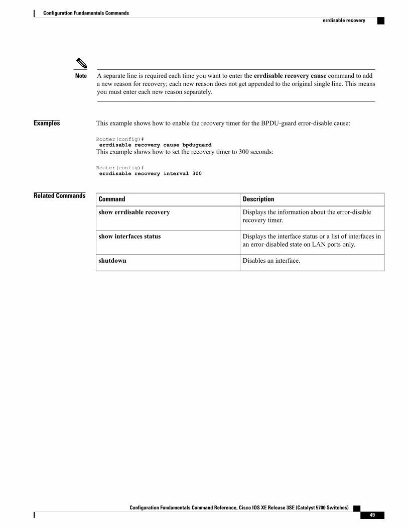
A separate line is required each time you want to enter the errdisable recovery cause command to adda new reason for recovery; each new reason does not get appended to the original single line. This meansyou must enter each new reason separately.
Note
Examples This example shows how to enable the recovery timer for the BPDU-guard error-disable cause:
Router(config)#errdisable recovery cause bpduguardThis example shows how to set the recovery timer to 300 seconds:
Router(config)#errdisable recovery interval 300
Related Commands DescriptionCommand
Displays the information about the error-disablerecovery timer.
show errdisable recovery
Displays the interface status or a list of interfaces inan error-disabled state on LAN ports only.
show interfaces status
Disables an interface.shutdown
Configuration Fundamentals Command Reference, Cisco IOS XE Release 3SE (Catalyst 5700 Switches) 49
Configuration Fundamentals Commandserrdisable recovery
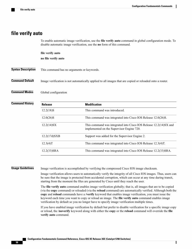
file verify autoTo enable automatic image verification, use the file verify auto command in global configuration mode. Todisable automatic image verification, use the no form of this command.
file verify auto
no file verify auto
Syntax Description This command has no arguments or keywords.
Command Default Image verification is not automatically applied to all images that are copied or reloaded onto a router.
Command Modes Global configuration
Command History ModificationRelease
This command was introduced.12.2(18)S
This command was integrated into Cisco IOS Release 12.0(26)S.12.0(26)S
This command was integrated into Cisco IOS Release 12.2(14)SX andimplemented on the Supervisor Engine 720.
12.2(14)SX
Support was added for the Supervisor Engine 2.12.2(17d)SXB
This command was integrated into Cisco IOS Release 12.3(4)T.12.3(4)T
This command was integrated into Cisco IOS Release 12.2(33)SRA.12.2(33)SRA
Usage Guidelines Image verification is accomplished by verifying the compressed Cisco IOS image checksum.
Image verification allows users to automatically verify the integrity of all Cisco IOS images. Thus, users canbe sure that the image is protected from accidental corruption, which can occur at any time during transit,starting from the moment the files are generated by Cisco until they reach the user.
The file verify auto command enables image verification globally; that is, all images that are to be copied(via the copy command) or reloaded (via the reload command) are automatically verified. Although both thecopy and reload commands have a /verify keyword that enables image verification, you must issue thekeyword each time you want to copy or reload an image. The file verify auto command enables imageverification by default so you no longer have to specify image verification multiple times.
If you have enabled image verification by default but prefer to disable verification for a specific image copyor reload, the /noverify keyword along with either the copy or the reload command will override the fileverify auto command.
Configuration Fundamentals Command Reference, Cisco IOS XE Release 3SE (Catalyst 5700 Switches)50
Configuration Fundamentals Commandsfile verify auto
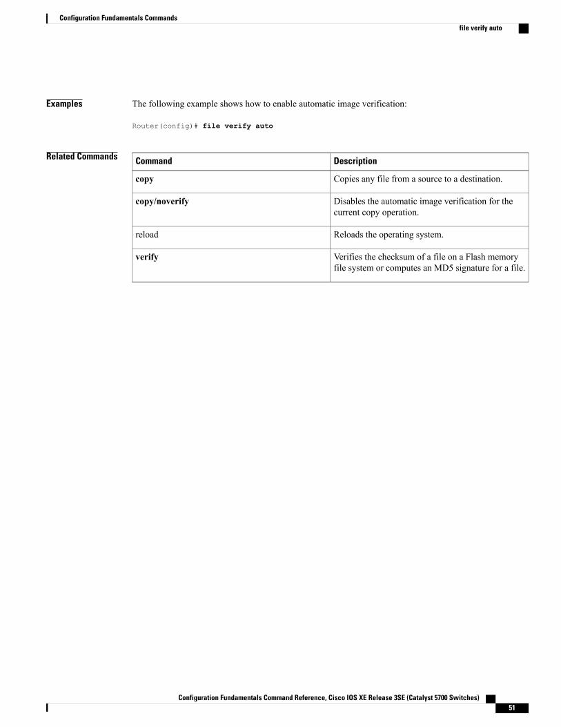
Examples The following example shows how to enable automatic image verification:
Router(config)# file verify auto
Related Commands DescriptionCommand
Copies any file from a source to a destination.copy
Disables the automatic image verification for thecurrent copy operation.
copy/noverify
Reloads the operating system.reload
Verifies the checksum of a file on a Flash memoryfile system or computes an MD5 signature for a file.
verify
Configuration Fundamentals Command Reference, Cisco IOS XE Release 3SE (Catalyst 5700 Switches) 51
Configuration Fundamentals Commandsfile verify auto
hostnameTo specify or modify the hostname for the network server, use the hostname command in global configurationmode.
hostname name
Syntax Description New hostname for the network server.name
Command Default The default hostname is Router.
Command Modes Global configuration
Command History ModificationRelease
This command was introduced.10.0
This command was integrated into Cisco IOS Release 12.2(33)SRA.12.2(33)SRA
This command was integrated into Cisco IOS Release 12.2(33)SB.12.2(33)SB
This command was integrated into Cisco IOS Release 12.2(33)SXI.12.2(33)SXI
This command was integrated into Cisco IOS XE Release 2.5.Cisco IOS XE Release 2.5
This command was integrated into Cisco IOS Release 15.0(1)M4 andsupport for numeric hostnames added.
15.0(1)M4
Usage Guidelines The hostname is used in prompts and default configuration filenames.
Do not expect case to be preserved. Uppercase and lowercase characters look the same to many internetsoftware applications. It may seem appropriate to capitalize a name the same way you might do in English,but conventions dictate that computer names appear all lowercase. For more information, refer to RFC 1178,Choosing a Name for Your Computer .
The name must also follow the rules for ARPANET hostnames. They must start with a letter, end with a letteror digit, and have as interior characters only letters, digits, and hyphens. Names must be 63 characters orfewer. Creating an all numeric hostname is not recommended but the name will be accepted after an error isreturned.
Router(config)#hostname 123% Hostname contains one or more illegal characters.123(config)#
Configuration Fundamentals Command Reference, Cisco IOS XE Release 3SE (Catalyst 5700 Switches)52
Configuration Fundamentals Commandshostname
A hostname of less than 10 characters is recommended. For more information, refer to RFC 1035, DomainNames--Implementation and Specification .
On most systems, a field of 30 characters is used for the hostname and the prompt in the CLI. Note that thelength of your hostname may cause longer configuration mode prompts to be truncated. For example, the fullprompt for service profile configuration mode is:
(config-service-profile)#
However, if you are using the hostname of “Router,” you will only see the following prompt (on most systems):
Router(config-service-profil)#
If the hostname is longer, you will see even less of the prompt:
Basement-rtr2(config-service)#
Keep this behavior in mind when assigning a name to your system (using the hostname global configurationcommand). If you expect that users will be relying on mode prompts as a CLI navigation aid, you shouldassign hostnames of no more than nine characters.
The use of a special character such as '\'(backslash) and a three or more digit number for the character settinglike hostname, results in incorrect translation:
Router(config)#Router(config)#hostname \99% Hostname contains one or more illegal characters.
Examples The following example changes the hostname to “host1”:
Router(config)# hostname host1host1(config)#
Related Commands DescriptionCommand
Enables you to make major changes to yourconfigurations, for example, adding a protocol suit,making major addressing scheme changes, orconfiguring newly installed interfaces.
setup
Configuration Fundamentals Command Reference, Cisco IOS XE Release 3SE (Catalyst 5700 Switches) 53
Configuration Fundamentals Commandshostname
reloadTo reload the operating system, use the reload command in privileged EXEC or diagnostic mode.
reload [/verify| /noverify] [[warm file] [line| in [hhh:mm| mmm [ text ]]| at hh:mm [day month] [ text ]]|reason [ reason-string ]| cancel]
Syntax Description (Optional) Verifies the digital signature of the filethat will be loaded onto the operating system.
/verify
(Optional) Does not verify the digital signature of thefile that will be loaded onto the operating system.
This keyword is often issued if the file verifyauto command is enabled, whichautomatically verifies the digital signatureof all images that are copied.
Note
/noverify
(Optional) Specifies warm rebooting.warm
(Optional) Specifies the image file for warmrebooting.
file
(Optional) Reason for reloading; the string can befrom 1 to 255 characters long.
line
(Optional) Schedules a reload of the software to takeeffect in the specified minutes or hours and minutes.The reload must take place within approximately 24days.
in hhh : mm | mmm
(Optional) Reason for reloading; the string can befrom 1 to 255 characters long.
text
(Optional) Schedules a reload of the software to takeplace at the specified time (using a 24-hour clock). Ifyou specify the month and day, the reload isscheduled to take place at the specified time and date.If you do not specify the month and day, the reloadtakes place at the specified time on the current day(if the specified time is later than the current time) oron the next day (if the specified time is earlier thanthe current time). Specifying 00:00 schedules thereload for midnight. The reloadmust take place within24 days.
at hh : mm
(Optional) Number of the day in the range from 1 to31.
day
Configuration Fundamentals Command Reference, Cisco IOS XE Release 3SE (Catalyst 5700 Switches)54
Configuration Fundamentals Commandsreload
Month of the year.month
(Optional) Specifies a reason for reloading.reason reason-string
(Optional) Cancels a scheduled reload.cancel
Command Modes Privileged EXEC (#) Diagnostic (diag)
Command History ModificationRelease
This command was introduced.10.0
This command was modified. Support for this command was added for theSupervisor Engine 720.
12.2(14)SX
This command was modified. The warm keyword was added.12.3(2)T
This command was integrated into Cisco IOS Release 12.2(18)S. The/verifyand /noverify keywords were added.
12.2(18)S
This command was modified. Support was added for the Cisco 7304 router.The Cisco 7500 series router in not supported in Cisco IOS Release 12.2(20)S.
12.2(20)S
This command was modified. The /verifyand /noverify keywords wereintegrated into Cisco IOS Release 12.0(26)S.
12.0(26)S
This command was modified. The /verifyand /noverify keywords wereintegrated into Cisco IOS Release 12.3(4)T.
12.3(4)T
This command was modified. Support for this command on the SupervisorEngine 2 was extended to Release 12.2(17d)SXB.
12.2(17d)SXB
This command was modified. The file keyword and url argument were added.12.3(11)T
This command was integrated into Cisco IOS Release 12.2(28)SB.12.2(28)SB
This command was integrated into Cisco IOS Release 12.2(33)SRA.12.2(33)SRA
This commandwasmodified. The reason keyword and reason-stringargumentwere added.
15.0(1)M
This command was introduced on the Cisco ASR 1000 Series AggregationServices Router and was made available in diagnostic mode.
Cisco IOS XE Release 2.1
Configuration Fundamentals Command Reference, Cisco IOS XE Release 3SE (Catalyst 5700 Switches) 55
Configuration Fundamentals Commandsreload
Usage Guidelines The reload command halts the system. If the system is set to restart on error, it reboots itself. Use the reloadcommand after configuration information is entered into a file and saved to the startup configuration.
You cannot reload from a virtual terminal if the system is not set up for automatic booting. This restrictionprevents the system from using an image stored in the ROMmonitor and taking the system out of the remoteuser’s control.If you modify your configuration file, the system prompts you to save the configuration. During a saveoperation, the system prompts whether you want to proceed with the save if the CONFIG_FILE variablepoints to a startup configuration file that no longer exists. If you respond “yes” in this situation, the systementers setup mode upon reload.
When you schedule a reload to occur at a later time (using the in keyword), it must take place within 24 days.
The at keyword can be used only if the system clock has been set on the router (either through Network TimeProtocol [NTP], the hardware calendar, or manually). The time is relative to the configured time zone on therouter. To schedule reloads across several routers to occur simultaneously, synchronize the time on each routerwith NTP.
When you specify the reload time using the at keyword, if you specify the month and day, the reload takesplace at the specified time and date. If you do not specify the month and day, the reload takes place at thespecified time on the current day (if the specified time is later than the current time), or on the next day (ifthe specified time is earlier than the current time). Specifying 00:00 schedules the reload for midnight. Thereload must take place within 24 days.
To display information about a scheduled reload, use the show reload command.
The /verify and /noverify Keywords
If the /verify keyword is specified, the integrity of the image will be verified before it is reloaded onto a router.If verification fails, the image reload will not occur. Image verification is important because it assures theuser that the image is protected from accidental corruption, which can occur at any time during transit, startingfrom the moment the files are generated by Cisco until they reach the user.
The /noverify keyword overrides any global automatic image verification that may be enabled via the fileverify auto command.
The warm Keyword
If you issue the reload command after you have configured thewarm-reboot global configuration command,a cold reboot will occur. Thus, if you want to reload your system, but do not want to override the warm rebootfunctionality, you should specify thewarm keyword with the reload command. The warm reboot functionalityallows a Cisco IOS image to reload without ROM monitor intervention. That is, read-write data is saved inRAM during a cold startup and restored during a warm reboot. Warm rebooting allows the router to rebootquicker than conventional rebooting (where control is transferred to ROM monitor and back to the image)because nothing is copied from flash to RAM.
Examples The following example shows how to immediately reload the software on the router:
Router# reloadThe following example shows how to reload the software on the router in 10 minutes:
Router# reload in 10Router# Reload scheduled for 11:57:08 PDT Fri Apr 21 1996 (in 10 minutes)Proceed with reload? [confirm]
Configuration Fundamentals Command Reference, Cisco IOS XE Release 3SE (Catalyst 5700 Switches)56
Configuration Fundamentals Commandsreload
The following example shows how to reload the software on the router at 1:00 p.m. on that day:
Router# reload at 13:00Router# Reload scheduled for 13:00:00 PDT Fri Apr 21 1996 (in 1 hour and 2 minutes)Proceed with reload? [confirm]The following example shows how to reload the software on the router on April 21 at 2:00 a.m.:
Router# reload at 02:00 apr 21Router# Reload scheduled for 02:00:00 PDT Sat Apr 21 1996 (in 38 hours and 9 minutes)Proceed with reload? [confirm]The following example shows how to cancel a pending reload:
Router# reload cancel%Reload cancelled.The following example shows how to perform a warm reboot at 4:00 a.m. on that day:
Router# reload warm at 04:00
The following example shows how to specify a reason for the reload:
Router# reload reason reloaded with updated version
The following example shows how to specify image verification via the /verify keyword before reloading animage onto the router:
Router# reload /verifyVerifying file integrity of bootflash:c7200-kboot-mz.121-8a.E%ERROR:Signature not found in file bootflash:c7200-kboot-mz.121-8a.E.Signature not present. Proceed with verify? [confirm]Verifying file disk0:c7200-js-mz......................................................................................................................................Done!Embedded Hash MD5 :CFA258948C4ECE52085DCF428A426DCDComputed Hash MD5 :CFA258948C4ECE52085DCF428A426DCDCCO Hash MD5 :44A7B9BDDD9638128C35528466318183Signature VerifiedProceed with reload? [confirm]n
Related Commands DescriptionCommand
Copies any file from a source to a destination.copy system:running-config nvram:startup-config
Enables automatic image verification.file verify auto
Displays the reload status on the router.show reload
Enables router reloading with reading images fromstorage.
warm-reboot
Configuration Fundamentals Command Reference, Cisco IOS XE Release 3SE (Catalyst 5700 Switches) 57
Configuration Fundamentals Commandsreload
remote-spanTo configure a virtual local area network (VLAN) as a remote switched port analyzer (RSPAN) VLAN, usethe remote-span command in config-VLAN mode. To remove the RSPAN designation, use the no form ofthis command.
remote-span
no remote-span
Syntax Description This command has no arguments or keywords.
Command Default This command has no default settings.
Command Modes Config-VLAN mode
Command History ModificationRelease
Support for this command was introduced on the Supervisor Engine 720.12.2(14)SX
Support for this command on the Supervisor Engine 2 was extended toRelease 12.2(17d)SXB.
12.2(17d)SXB
This command was integrated into Cisco IOS Release 12.2(33)SRA.12.2(33)SRA
Usage Guidelines This command is not supported in the VLAN database mode.
You can enter the show vlan remote-span command to display the RSPAN VLANs in the Cisco 7600 seriesrouter.
Examples This example shows how to configure a VLAN as an RSPAN VLAN:
Router(config-vlan)# remote-spanRouter(config-vlan)This example shows how to remove the RSPAN designation:
Router(config-vlan)# no remote-spanRouter(config-vlan)
Related Commands DescriptionConnect
Displays a list of RSPAN VLANs.show vlan remote-span
Configuration Fundamentals Command Reference, Cisco IOS XE Release 3SE (Catalyst 5700 Switches)58
Configuration Fundamentals Commandsremote-span
setupTo enter Setup mode, use the setup command in privileged EXEC mode.
setup
Syntax Description This command has no arguments or keywords.
Command Modes Privileged EXEC
Command History ModificationRelease
This command was introduced.11.1
This command was integrated into Cisco IOS Release 12.2(33)SRA.12.2(33)SRA
Usage Guidelines Setup mode gives you the option of configuring your system without using the Cisco IOS Command LineInterface (CLI). For some tasks, you may find it easier to use Setup than to enter Cisco IOS commandsindividually. For example, you might want to use Setup to add a protocol suite, to make major addressingscheme changes, or to configure a newly installed interface. Although you can use the CLI to make thesechanges, Setup provides you with a high-level view of the configuration and guides you through theconfiguration process.
If you are not familiar with Cisco products and the CLI, Setup is a particularly valuable tool because it promptsyou for the specific information required to configure your system.
If you use the Setup mode to modify a configuration because you have added or modified the hardware,be sure to verify the physical connections using the show version EXEC command. Also, verify the logicalport assignments using the show running-config EXEC command to ensure that you configure the correctport. Refer to the hardware documentation for your platform for more information on physical and logicalport assignments.
Note
Before using the Setup mode, you should have the following information so that you can configure the systemproperly:
• Which interfaces you want to configure
• Which routing protocols you wish to enable
• Whether the router is to perform bridging
• Network addresses for the protocols being configured
• Password strategy for your environment
Configuration Fundamentals Command Reference, Cisco IOS XE Release 3SE (Catalyst 5700 Switches) 59
Configuration Fundamentals Commandssetup
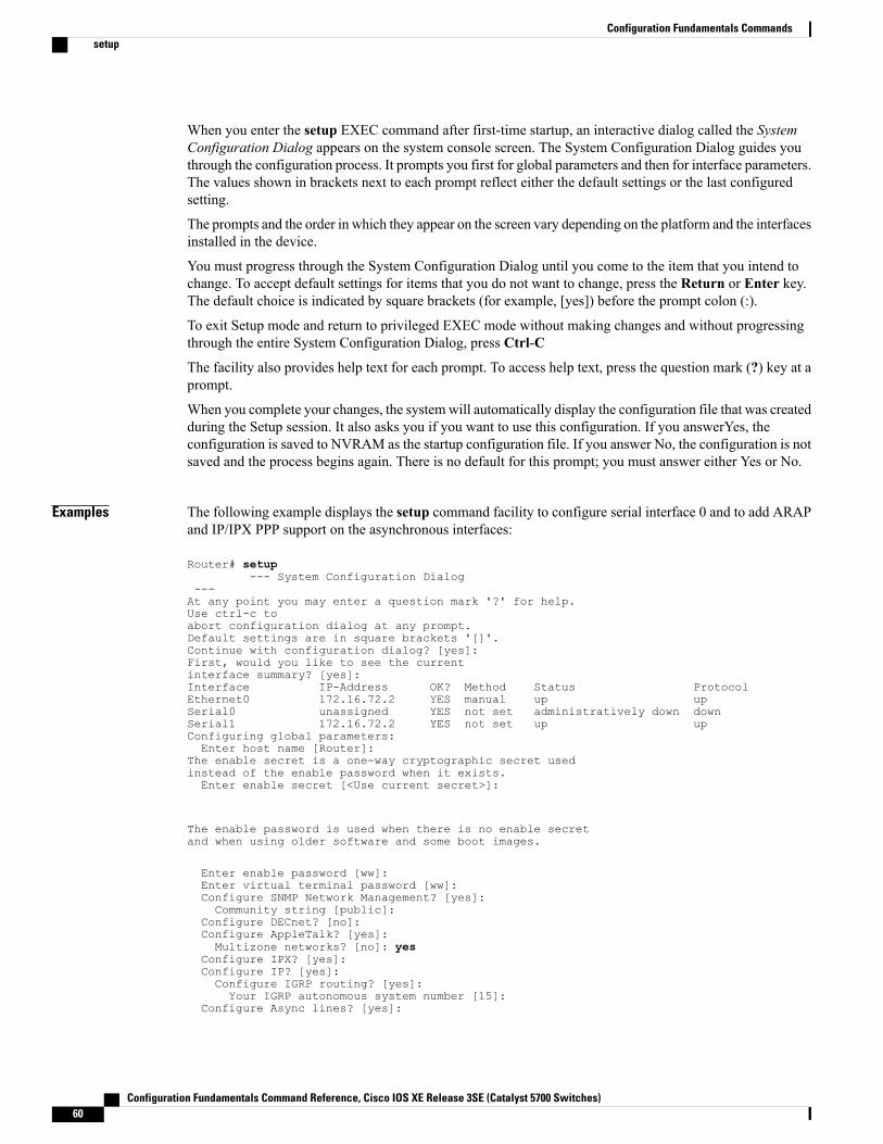
When you enter the setup EXEC command after first-time startup, an interactive dialog called the SystemConfiguration Dialog appears on the system console screen. The System Configuration Dialog guides youthrough the configuration process. It prompts you first for global parameters and then for interface parameters.The values shown in brackets next to each prompt reflect either the default settings or the last configuredsetting.
The prompts and the order in which they appear on the screen vary depending on the platform and the interfacesinstalled in the device.
You must progress through the System Configuration Dialog until you come to the item that you intend tochange. To accept default settings for items that you do not want to change, press the Return or Enter key.The default choice is indicated by square brackets (for example, [yes]) before the prompt colon (:).
To exit Setup mode and return to privileged EXEC mode without making changes and without progressingthrough the entire System Configuration Dialog, press Ctrl-C
The facility also provides help text for each prompt. To access help text, press the question mark (?) key at aprompt.
When you complete your changes, the systemwill automatically display the configuration file that was createdduring the Setup session. It also asks you if you want to use this configuration. If you answerYes, theconfiguration is saved to NVRAM as the startup configuration file. If you answer No, the configuration is notsaved and the process begins again. There is no default for this prompt; you must answer either Yes or No.
Examples The following example displays the setup command facility to configure serial interface 0 and to add ARAPand IP/IPX PPP support on the asynchronous interfaces:
Router# setup--- System Configuration Dialog
---At any point you may enter a question mark '?' for help.Use ctrl-c toabort configuration dialog at any prompt.Default settings are in square brackets '[]'.Continue with configuration dialog? [yes]:First, would you like to see the currentinterface summary? [yes]:Interface IP-Address OK? Method Status ProtocolEthernet0 172.16.72.2 YES manual up upSerial0 unassigned YES not set administratively down downSerial1 172.16.72.2 YES not set up upConfiguring global parameters:Enter host name [Router]:
The enable secret is a one-way cryptographic secret usedinstead of the enable password when it exists.Enter enable secret [<Use current secret>]:
The enable password is used when there is no enable secretand when using older software and some boot images.
Enter enable password [ww]:Enter virtual terminal password [ww]:Configure SNMP Network Management? [yes]:Community string [public]:
Configure DECnet? [no]:Configure AppleTalk? [yes]:Multizone networks? [no]: yes
Configure IPX? [yes]:Configure IP? [yes]:Configure IGRP routing? [yes]:Your IGRP autonomous system number [15]:
Configure Async lines? [yes]:
Configuration Fundamentals Command Reference, Cisco IOS XE Release 3SE (Catalyst 5700 Switches)60
Configuration Fundamentals Commandssetup
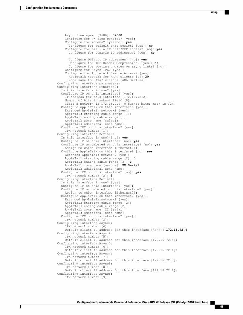
Async line speed [9600]: 57600Configure for HW flow control? [yes]:Configure for modems? [yes/no]: yesConfigure for default chat script? [yes]: no
Configure for Dial-in IP SLIP/PPP access? [no]: yesConfigure for Dynamic IP addresses? [yes]: no
Configure Default IP addresses? [no]: yesConfigure for TCP Header Compression? [yes]: noConfigure for routing updates on async links? [no]:
Configure for Async IPX? [yes]:Configure for Appletalk Remote Access? [yes]:AppleTalk Network for ARAP clients [1]: 20Zone name for ARAP clients [ARA Dialins]:
Configuring interface parameters:Configuring interface Ethernet0:Is this interface in use? [yes]:Configure IP on this interface? [yes]:IP address for this interface [172.16.72.2]:Number of bits in subnet field [8]:Class B network is 172.16.0.0, 8 subnet bits; mask is /24
Configure AppleTalk on this interface? [yes]:Extended AppleTalk network? [yes]:AppleTalk starting cable range [1]:AppleTalk ending cable range [1]:AppleTalk zone name [Sales]:AppleTalk additional zone name:
Configure IPX on this interface? [yes]:IPX network number [1]:
Configuring interface Serial0:Is this interface in use? [no]: yesConfigure IP on this interface? [no]: yesConfigure IP unnumbered on this interface? [no]: yesAssign to which interface [Ethernet0]:
Configure AppleTalk on this interface? [no]: yesExtended AppleTalk network? [yes]:AppleTalk starting cable range [2]: 3AppleTalk ending cable range [3]: 3AppleTalk zone name [myzone]: ZZ SerialAppleTalk additional zone name:
Configure IPX on this interface? [no]: yesIPX network number [2]: 3
Configuring interface Serial1:Is this interface in use? [yes]:Configure IP on this interface? [yes]:Configure IP unnumbered on this interface? [yes]:Assign to which interface [Ethernet0]:
Configure AppleTalk on this interface? [yes]:Extended AppleTalk network? [yes]:AppleTalk starting cable range [2]:AppleTalk ending cable range [2]:AppleTalk zone name [ZZ Serial]:AppleTalk additional zone name:
Configure IPX on this interface? [yes]:IPX network number [2]:
Configuring interface Async1:IPX network number [4]:Default client IP address for this interface [none]: 172.16.72.4
Configuring interface Async2:IPX network number [5]:Default client IP address for this interface [172.16.72.5]:
Configuring interface Async3:IPX network number [6]:Default client IP address for this interface [172.16.72.6]:
Configuring interface Async4:IPX network number [7]:Default client IP address for this interface [172.16.72.7]:
Configuring interface Async5:IPX network number [8]:Default client IP address for this interface [172.16.72.8]:
Configuring interface Async6:IPX network number [9]:
Configuration Fundamentals Command Reference, Cisco IOS XE Release 3SE (Catalyst 5700 Switches) 61
Configuration Fundamentals Commandssetup
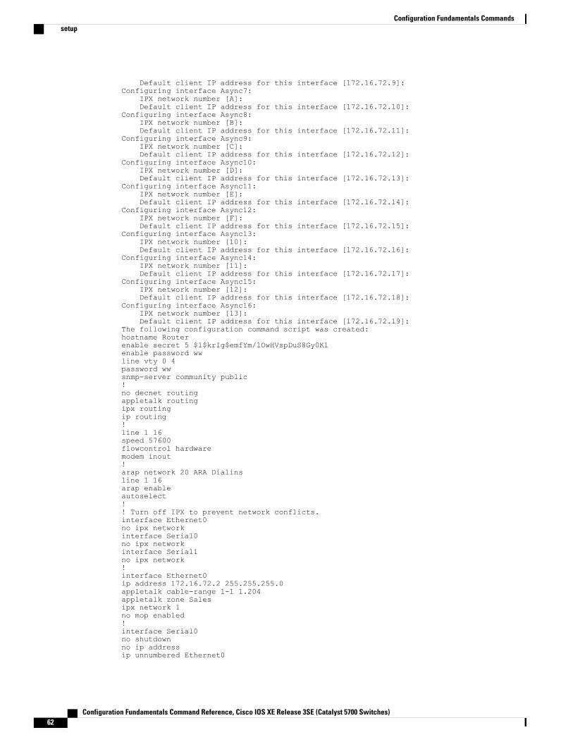
Default client IP address for this interface [172.16.72.9]:Configuring interface Async7:
IPX network number [A]:Default client IP address for this interface [172.16.72.10]:
Configuring interface Async8:IPX network number [B]:Default client IP address for this interface [172.16.72.11]:
Configuring interface Async9:IPX network number [C]:Default client IP address for this interface [172.16.72.12]:
Configuring interface Async10:IPX network number [D]:Default client IP address for this interface [172.16.72.13]:
Configuring interface Async11:IPX network number [E]:Default client IP address for this interface [172.16.72.14]:
Configuring interface Async12:IPX network number [F]:Default client IP address for this interface [172.16.72.15]:
Configuring interface Async13:IPX network number [10]:Default client IP address for this interface [172.16.72.16]:
Configuring interface Async14:IPX network number [11]:Default client IP address for this interface [172.16.72.17]:
Configuring interface Async15:IPX network number [12]:Default client IP address for this interface [172.16.72.18]:
Configuring interface Async16:IPX network number [13]:Default client IP address for this interface [172.16.72.19]:
The following configuration command script was created:hostname Routerenable secret 5 $1$krIg$emfYm/1OwHVspDuS8Gy0K1enable password wwline vty 0 4password wwsnmp-server community public!no decnet routingappletalk routingipx routingip routing!line 1 16speed 57600flowcontrol hardwaremodem inout!arap network 20 ARA Dialinsline 1 16arap enableautoselect!! Turn off IPX to prevent network conflicts.interface Ethernet0no ipx networkinterface Serial0no ipx networkinterface Serial1no ipx network!interface Ethernet0ip address 172.16.72.2 255.255.255.0appletalk cable-range 1-1 1.204appletalk zone Salesipx network 1no mop enabled!interface Serial0no shutdownno ip addressip unnumbered Ethernet0
Configuration Fundamentals Command Reference, Cisco IOS XE Release 3SE (Catalyst 5700 Switches)62
Configuration Fundamentals Commandssetup
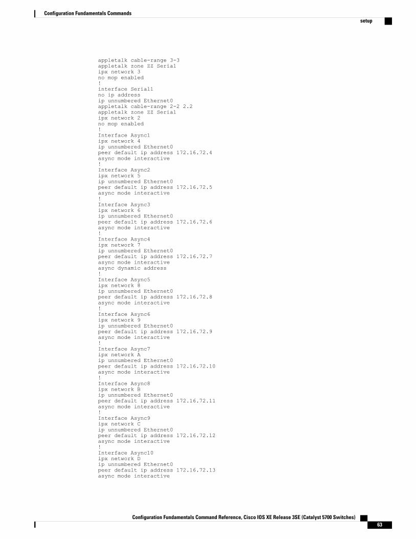
appletalk cable-range 3-3appletalk zone ZZ Serialipx network 3no mop enabled!interface Serial1no ip addressip unnumbered Ethernet0appletalk cable-range 2-2 2.2appletalk zone ZZ Serialipx network 2no mop enabled!Interface Async1ipx network 4ip unnumbered Ethernet0peer default ip address 172.16.72.4async mode interactive!Interface Async2ipx network 5ip unnumbered Ethernet0peer default ip address 172.16.72.5async mode interactive!Interface Async3ipx network 6ip unnumbered Ethernet0peer default ip address 172.16.72.6async mode interactive!Interface Async4ipx network 7ip unnumbered Ethernet0peer default ip address 172.16.72.7async mode interactiveasync dynamic address!Interface Async5ipx network 8ip unnumbered Ethernet0peer default ip address 172.16.72.8async mode interactive!Interface Async6ipx network 9ip unnumbered Ethernet0peer default ip address 172.16.72.9async mode interactive!Interface Async7ipx network Aip unnumbered Ethernet0peer default ip address 172.16.72.10async mode interactive!Interface Async8ipx network Bip unnumbered Ethernet0peer default ip address 172.16.72.11async mode interactive!Interface Async9ipx network Cip unnumbered Ethernet0peer default ip address 172.16.72.12async mode interactive!Interface Async10ipx network Dip unnumbered Ethernet0peer default ip address 172.16.72.13async mode interactive
Configuration Fundamentals Command Reference, Cisco IOS XE Release 3SE (Catalyst 5700 Switches) 63
Configuration Fundamentals Commandssetup
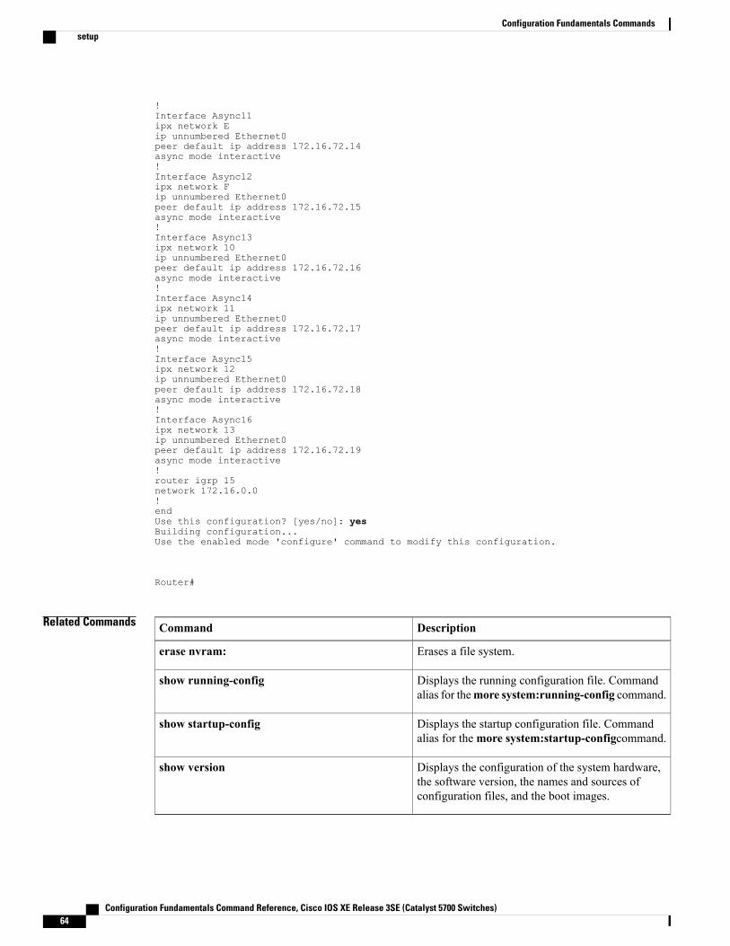
!Interface Async11ipx network Eip unnumbered Ethernet0peer default ip address 172.16.72.14async mode interactive!Interface Async12ipx network Fip unnumbered Ethernet0peer default ip address 172.16.72.15async mode interactive!Interface Async13ipx network 10ip unnumbered Ethernet0peer default ip address 172.16.72.16async mode interactive!Interface Async14ipx network 11ip unnumbered Ethernet0peer default ip address 172.16.72.17async mode interactive!Interface Async15ipx network 12ip unnumbered Ethernet0peer default ip address 172.16.72.18async mode interactive!Interface Async16ipx network 13ip unnumbered Ethernet0peer default ip address 172.16.72.19async mode interactive!router igrp 15network 172.16.0.0!endUse this configuration? [yes/no]: yesBuilding configuration...Use the enabled mode 'configure' command to modify this configuration.
Router#
Related Commands DescriptionCommand
Erases a file system.erase nvram:
Displays the running configuration file. Commandalias for themore system:running-config command.
show running-config
Displays the startup configuration file. Commandalias for themore system:startup-configcommand.
show startup-config
Displays the configuration of the system hardware,the software version, the names and sources ofconfiguration files, and the boot images.
show version
Configuration Fundamentals Command Reference, Cisco IOS XE Release 3SE (Catalyst 5700 Switches)64
Configuration Fundamentals Commandssetup
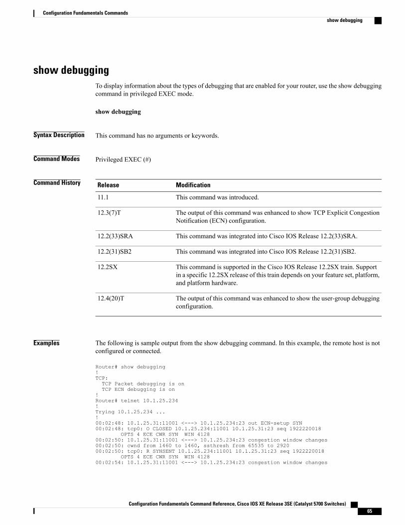
show debuggingTo display information about the types of debugging that are enabled for your router, use the show debuggingcommand in privileged EXEC mode.
show debugging
Syntax Description This command has no arguments or keywords.
Command Modes Privileged EXEC (#)
Command History ModificationRelease
This command was introduced.11.1
The output of this command was enhanced to show TCP Explicit CongestionNotification (ECN) configuration.
12.3(7)T
This command was integrated into Cisco IOS Release 12.2(33)SRA.12.2(33)SRA
This command was integrated into Cisco IOS Release 12.2(31)SB2.12.2(31)SB2
This command is supported in the Cisco IOS Release 12.2SX train. Supportin a specific 12.2SX release of this train depends on your feature set, platform,and platform hardware.
12.2SX
The output of this command was enhanced to show the user-group debuggingconfiguration.
12.4(20)T
Examples The following is sample output from the show debugging command. In this example, the remote host is notconfigured or connected.
Router# show debugging!TCP:TCP Packet debugging is onTCP ECN debugging is on
!Router# telnet 10.1.25.234!Trying 10.1.25.234 ...!00:02:48: 10.1.25.31:11001 <---> 10.1.25.234:23 out ECN-setup SYN00:02:48: tcp0: O CLOSED 10.1.25.234:11001 10.1.25.31:23 seq 1922220018
OPTS 4 ECE CWR SYN WIN 412800:02:50: 10.1.25.31:11001 <---> 10.1.25.234:23 congestion window changes00:02:50: cwnd from 1460 to 1460, ssthresh from 65535 to 292000:02:50: tcp0: R SYNSENT 10.1.25.234:11001 10.1.25.31:23 seq 1922220018
OPTS 4 ECE CWR SYN WIN 412800:02:54: 10.1.25.31:11001 <---> 10.1.25.234:23 congestion window changes
Configuration Fundamentals Command Reference, Cisco IOS XE Release 3SE (Catalyst 5700 Switches) 65
Configuration Fundamentals Commandsshow debugging
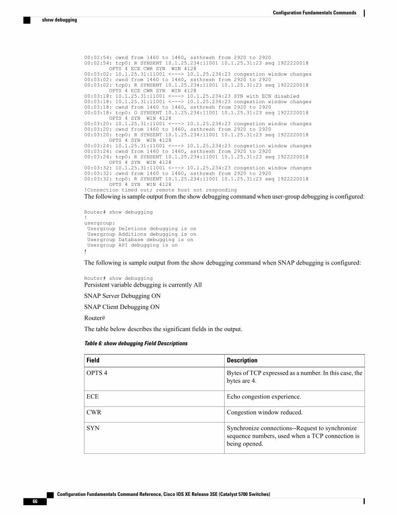
00:02:54: cwnd from 1460 to 1460, ssthresh from 2920 to 292000:02:54: tcp0: R SYNSENT 10.1.25.234:11001 10.1.25.31:23 seq 1922220018
OPTS 4 ECE CWR SYN WIN 412800:03:02: 10.1.25.31:11001 <---> 10.1.25.234:23 congestion window changes00:03:02: cwnd from 1460 to 1460, ssthresh from 2920 to 292000:03:02: tcp0: R SYNSENT 10.1.25.234:11001 10.1.25.31:23 seq 1922220018
OPTS 4 ECE CWR SYN WIN 412800:03:18: 10.1.25.31:11001 <---> 10.1.25.234:23 SYN with ECN disabled00:03:18: 10.1.25.31:11001 <---> 10.1.25.234:23 congestion window changes00:03:18: cwnd from 1460 to 1460, ssthresh from 2920 to 292000:03:18: tcp0: O SYNSENT 10.1.25.234:11001 10.1.25.31:23 seq 1922220018
OPTS 4 SYN WIN 412800:03:20: 10.1.25.31:11001 <---> 10.1.25.234:23 congestion window changes00:03:20: cwnd from 1460 to 1460, ssthresh from 2920 to 292000:03:20: tcp0: R SYNSENT 10.1.25.234:11001 10.1.25.31:23 seq 1922220018
OPTS 4 SYN WIN 412800:03:24: 10.1.25.31:11001 <---> 10.1.25.234:23 congestion window changes00:03:24: cwnd from 1460 to 1460, ssthresh from 2920 to 292000:03:24: tcp0: R SYNSENT 10.1.25.234:11001 10.1.25.31:23 seq 1922220018
OPTS 4 SYN WIN 412800:03:32: 10.1.25.31:11001 <---> 10.1.25.234:23 congestion window changes00:03:32: cwnd from 1460 to 1460, ssthresh from 2920 to 292000:03:32: tcp0: R SYNSENT 10.1.25.234:11001 10.1.25.31:23 seq 1922220018
OPTS 4 SYN WIN 4128!Connection timed out; remote host not respondingThe following is sample output from the show debugging commandwhen user-group debugging is configured:
Router# show debugging!usergroup:Usergroup Deletions debugging is onUsergroup Additions debugging is onUsergroup Database debugging is onUsergroup API debugging is on!
The following is sample output from the show debugging command when SNAP debugging is configured:
Router# show debuggingPersistent variable debugging is currently All
SNAP Server Debugging ON
SNAP Client Debugging ON
Router#
The table below describes the significant fields in the output.
Table 6: show debugging Field Descriptions
DescriptionField
Bytes of TCP expressed as a number. In this case, thebytes are 4.
OPTS 4
Echo congestion experience.ECE
Congestion window reduced.CWR
Synchronize connections--Request to synchronizesequence numbers, used when a TCP connection isbeing opened.
SYN
Configuration Fundamentals Command Reference, Cisco IOS XE Release 3SE (Catalyst 5700 Switches)66
Configuration Fundamentals Commandsshow debugging
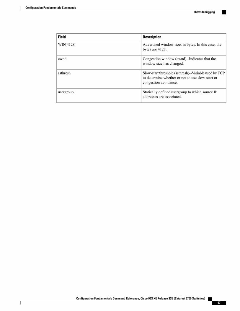
DescriptionField
Advertised window size, in bytes. In this case, thebytes are 4128.
WIN 4128
Congestion window (cwnd)--Indicates that thewindow size has changed.
cwnd
Slow-start threshold (ssthresh)--Variable used by TCPto determine whether or not to use slow-start orcongestion avoidance.
ssthresh
Statically defined usergroup to which source IPaddresses are associated.
usergroup
Configuration Fundamentals Command Reference, Cisco IOS XE Release 3SE (Catalyst 5700 Switches) 67
Configuration Fundamentals Commandsshow debugging
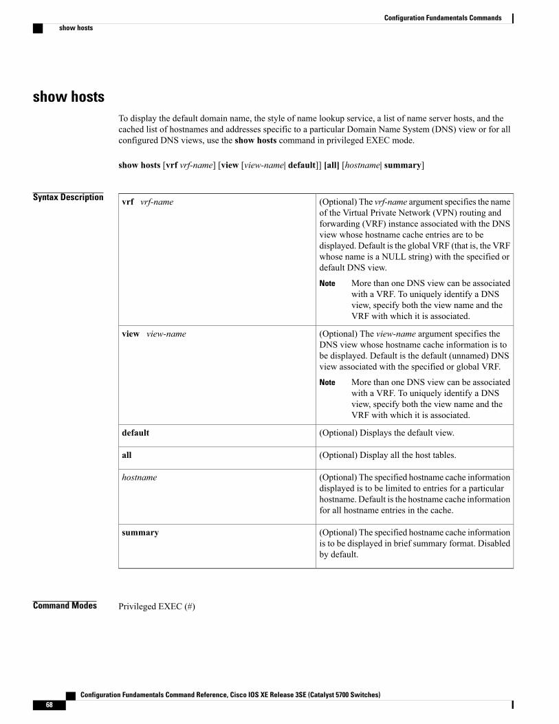
show hostsTo display the default domain name, the style of name lookup service, a list of name server hosts, and thecached list of hostnames and addresses specific to a particular Domain Name System (DNS) view or for allconfigured DNS views, use the show hosts command in privileged EXEC mode.
show hosts [vrf vrf-name] [view [view-name| default]] [all] [hostname| summary]
Syntax Description (Optional) The vrf-name argument specifies the nameof the Virtual Private Network (VPN) routing andforwarding (VRF) instance associated with the DNSview whose hostname cache entries are to bedisplayed. Default is the global VRF (that is, the VRFwhose name is a NULL string) with the specified ordefault DNS view.
More than one DNS view can be associatedwith a VRF. To uniquely identify a DNSview, specify both the view name and theVRF with which it is associated.
Note
vrf vrf-name
(Optional) The view-name argument specifies theDNS view whose hostname cache information is tobe displayed. Default is the default (unnamed) DNSview associated with the specified or global VRF.
More than one DNS view can be associatedwith a VRF. To uniquely identify a DNSview, specify both the view name and theVRF with which it is associated.
Note
view view-name
(Optional) Displays the default view.default
(Optional) Display all the host tables.all
(Optional) The specified hostname cache informationdisplayed is to be limited to entries for a particularhostname. Default is the hostname cache informationfor all hostname entries in the cache.
hostname
(Optional) The specified hostname cache informationis to be displayed in brief summary format. Disabledby default.
summary
Command Modes Privileged EXEC (#)
Configuration Fundamentals Command Reference, Cisco IOS XE Release 3SE (Catalyst 5700 Switches)68
Configuration Fundamentals Commandsshow hosts
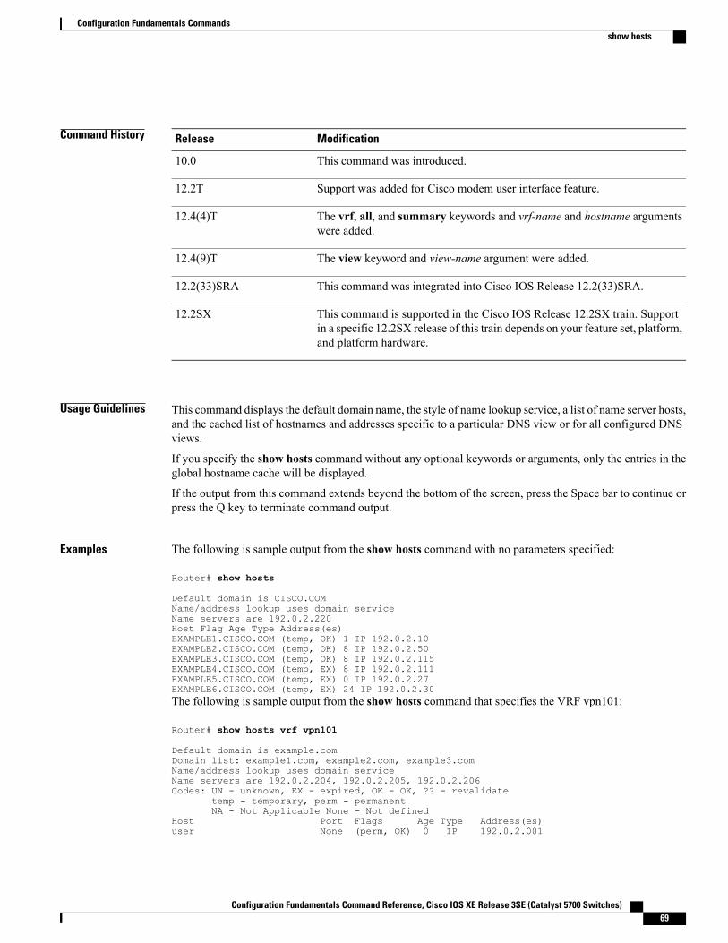
Command History ModificationRelease
This command was introduced.10.0
Support was added for Cisco modem user interface feature.12.2T
The vrf, all, and summary keywords and vrf-name and hostname argumentswere added.
12.4(4)T
The view keyword and view-name argument were added.12.4(9)T
This command was integrated into Cisco IOS Release 12.2(33)SRA.12.2(33)SRA
This command is supported in the Cisco IOS Release 12.2SX train. Supportin a specific 12.2SX release of this train depends on your feature set, platform,and platform hardware.
12.2SX
Usage Guidelines This command displays the default domain name, the style of name lookup service, a list of name server hosts,and the cached list of hostnames and addresses specific to a particular DNS view or for all configured DNSviews.
If you specify the show hosts command without any optional keywords or arguments, only the entries in theglobal hostname cache will be displayed.
If the output from this command extends beyond the bottom of the screen, press the Space bar to continue orpress the Q key to terminate command output.
Examples The following is sample output from the show hosts command with no parameters specified:
Router# show hosts
Default domain is CISCO.COMName/address lookup uses domain serviceName servers are 192.0.2.220Host Flag Age Type Address(es)EXAMPLE1.CISCO.COM (temp, OK) 1 IP 192.0.2.10EXAMPLE2.CISCO.COM (temp, OK) 8 IP 192.0.2.50EXAMPLE3.CISCO.COM (temp, OK) 8 IP 192.0.2.115EXAMPLE4.CISCO.COM (temp, EX) 8 IP 192.0.2.111EXAMPLE5.CISCO.COM (temp, EX) 0 IP 192.0.2.27EXAMPLE6.CISCO.COM (temp, EX) 24 IP 192.0.2.30The following is sample output from the show hosts command that specifies the VRF vpn101:
Router# show hosts vrf vpn101
Default domain is example.comDomain list: example1.com, example2.com, example3.comName/address lookup uses domain serviceName servers are 192.0.2.204, 192.0.2.205, 192.0.2.206Codes: UN - unknown, EX - expired, OK - OK, ?? - revalidate
temp - temporary, perm - permanentNA - Not Applicable None - Not defined
Host Port Flags Age Type Address(es)user None (perm, OK) 0 IP 192.0.2.001
Configuration Fundamentals Command Reference, Cisco IOS XE Release 3SE (Catalyst 5700 Switches) 69
Configuration Fundamentals Commandsshow hosts
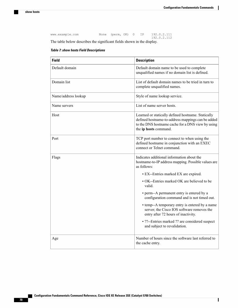
www.example.com None (perm, OK) 0 IP 192.0.2.111192.0.2.112
The table below describes the significant fields shown in the display.
Table 7: show hosts Field Descriptions
DescriptionField
Default domain name to be used to completeunqualified names if no domain list is defined.
Default domain
List of default domain names to be tried in turn tocomplete unqualified names.
Domain list
Style of name lookup service.Name/address lookup
List of name server hosts.Name servers
Learned or statically defined hostname. Staticallydefined hostname-to-address mappings can be addedto the DNS hostname cache for a DNS view by usingthe ip hosts command.
Host
TCP port number to connect to when using thedefined hostname in conjunction with an EXECconnect or Telnet command.
Port
Indicates additional information about thehostname-to-IP address mapping. Possible values areas follows:
• EX--Entries marked EX are expired.
• OK--Entries marked OK are believed to bevalid.
• perm--A permanent entry is entered by aconfiguration command and is not timed out.
• temp--A temporary entry is entered by a nameserver; the Cisco IOS software removes theentry after 72 hours of inactivity.
• ??--Entries marked ?? are considered suspectand subject to revalidation.
Flags
Number of hours since the software last referred tothe cache entry.
Age
Configuration Fundamentals Command Reference, Cisco IOS XE Release 3SE (Catalyst 5700 Switches)70
Configuration Fundamentals Commandsshow hosts
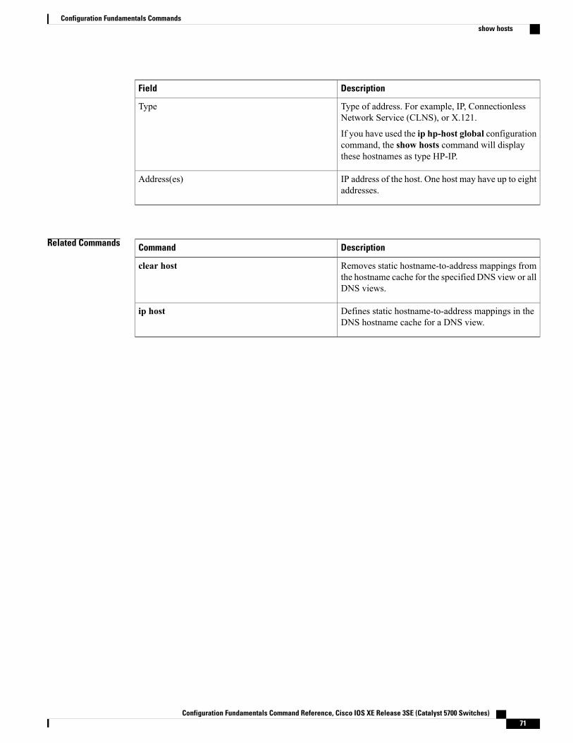
DescriptionField
Type of address. For example, IP, ConnectionlessNetwork Service (CLNS), or X.121.
If you have used the ip hp-host global configurationcommand, the show hosts command will displaythese hostnames as type HP-IP.
Type
IP address of the host. One host may have up to eightaddresses.
Address(es)
Related Commands DescriptionCommand
Removes static hostname-to-address mappings fromthe hostname cache for the specified DNS view or allDNS views.
clear host
Defines static hostname-to-address mappings in theDNS hostname cache for a DNS view.
ip host
Configuration Fundamentals Command Reference, Cisco IOS XE Release 3SE (Catalyst 5700 Switches) 71
Configuration Fundamentals Commandsshow hosts
show inventoryTo display the product inventory listing of all Cisco products installed in the networking device, use the showinventory command in user EXEC or privileged EXEC mode.
show inventory [raw] [entity]
Syntax Description (Optional) Retrieves information about all of theCisco products--referred to as entities--installed inthe Cisco networking device, even if the entities donot have a product ID (PID) value, a unique deviceidentifier (UDI), or other physical identification.
raw
(Optional) Name of a Cisco entity (for example,chassis, backplane, module, or slot). A quoted stringmay be used to display very specific UDI information;for example “sfslot 1” will display the UDIinformation for slot 1 of an entity named sfslot.
entity
Command Modes User EXEC Privileged EXEC
Command History ModificationRelease
This command was introduced.12.3(4)T
This command was integrated into Cisco IOS Release 12.0(27)S.12.0(27)S
This command was integrated into Cisco IOS Release 12.2(25)S.12.2(25)S
This command was integrated into Cisco IOS Release 12.2(27)SBC.12.2(27)SBC
This command was integrated into Cisco IOS Release 12.2(18)SXE5.12.2(18)SXE5
Usage Guidelines The show inventory command retrieves and displays inventory information about each Cisco product in theform of a UDI. The UDI is a combination of three separate data elements: a product identifier (PID), a versionidentifier (VID), and the serial number (SN).
The PID is the name by which the product can be ordered; it has been historically called the “Product Name”or “Part Number.” This is the identifier that one would use to order an exact replacement part.The VID is the version of the product. Whenever a product has been revised, the VID will be incremented.The VID is incremented according to a rigorous process derived from Telcordia GR-209-CORE, an industryguideline that governs product change notices.
Configuration Fundamentals Command Reference, Cisco IOS XE Release 3SE (Catalyst 5700 Switches)72
Configuration Fundamentals Commandsshow inventory
The SN is the vendor-unique serialization of the product. Eachmanufactured product will carry a unique serialnumber assigned at the factory, which cannot be changed in the field. This is the means by which to identifyan individual, specific instance of a product.
The UDI refers to each product as an entity. Some entities, such as a chassis, will have subentities like slots.Each entity will display on a separate line in a logically ordered presentation that is arranged hierarchicallyby Cisco entities.
Use the show inventory command without options to display a list of Cisco entities installed in the networkingdevice that are assigned a PID.
Examples The following is sample output from the show inventorycommand without any keywords or arguments. Thissample output displays a list of Cisco entities installed in a router that are assigned a PID.
Router# show inventoryNAME: “Chassis”, DESCR: “12008/GRP chassis”PID: GSR8/40 , VID: V01, SN: 63915640NAME: “slot 0”, DESCR: “GRP”PID: GRP-B , VID: V01, SN: CAB021300R5NAME: “slot 1”, DESCR: “4 port ATM OC3 multimode”PID: 4OC3/ATM-MM-SC , VID: V01, SN: CAB04036GT1NAME: “slot 3”, DESCR: “4 port 0C3 POS multimode”PID: LC-4OC3/POS-MM , VID: V01, SN: CAB014900GUNAME: “slot 5”, DESCR: “1 port Gigabit Ethernet”PID: GE-GBIC-SC-B , VID: V01, SN: CAB034251NXNAME: “slot 7”, DESCR: “GRP”PID: GRP-B , VID: V01, SN: CAB0428AN4ONAME: “slot 16”, DESCR: “GSR 12008 Clock Scheduler Card”PID: GSR8-CSC/ALRM , VID: V01, SN: CAB0429AUYHNAME: “sfslot 1”, DESCR: “GSR 12008 Switch Fabric Card”PID: GSR8-SFC , VID: V01, SN: CAB0428ALOSNAME: “sfslot 2”, DESCR: “GSR 12008 Switch Fabric Card”PID: GSR8-SFC , VID: V01, SN: CAB0429AU0MNAME: “sfslot 3”, DESCR: “GSR 12008 Switch Fabric Card”PID: GSR8-SFC , VID: V01, SN: CAB0429ARD7NAME: “PSslot 1”, DESCR: “GSR 12008 AC Power Supply”PID: FWR-GSR8-AC-B , VID: V01, SN: CAB041999CWThe table below describes the fields shown in the display.
Table 8: show inventory Field Descriptions
DescriptionField
Physical name (text string) assigned to the Ciscoentity. For example, console or a simple componentnumber (port or module number), such as “1,”depending on the physical component naming syntaxof the device.
NAME
Physical description of the Cisco entity thatcharacterizes the object. The physical descriptionincludes the hardware serial number and the hardwarerevision.
DESCR
Entity product identifier. Equivalent to theentPhysicalModelName MIB variable in RFC 2737.
PID
Configuration Fundamentals Command Reference, Cisco IOS XE Release 3SE (Catalyst 5700 Switches) 73
Configuration Fundamentals Commandsshow inventory
DescriptionField
Entity version identifier. Equivalent to theentPhysicalHardwareRevMIB variable in RFC 2737.
VID
Entity serial number. Equivalent to theentPhysicalSerialNum MIB variable in RFC 2737.
SN
For diagnostic purposes, the show inventorycommand can be used with the raw keyword to display everyRFC 2737 entity including those without a PID, UDI, or other physical identification.
The raw keyword option is primarily intended for troubleshooting problems with the show inventorycommand itself.
Note
Router# show inventory rawNAME: “Chassis”, DESCR: “12008/GRP chassis”PID: , VID: V01, SN: 63915640NAME: “slot 0”, DESCR: “GRP”PID: , VID: V01, SN: CAB021300R5NAME: “slot 1”, DESCR: “4 port ATM OC3 multimode”PID: 4OC3/ATM-MM-SC , VID: V01, SN: CAB04036GT1NAME: “slot 3”, DESCR: “4 port 0C3 POS multimode”PID: LC-4OC3/POS-MM , VID: V01, SN: CAB014900GUEnter the show inventorycommandwith an entity argument value to display the UDI information for a specifictype of Cisco entity installed in the networking device. In this example, a list of Cisco entities that match thesfslot argument string is displayed.
Router# show inventory sfslotNAME: “sfslot 1”, DESCR: “GSR 12008 Switch Fabric Card”PID: GSR8-SFC , VID: V01, SN: CAB0428ALOSNAME: “sfslot 2”, DESCR: “GSR 12008 Switch Fabric Card”PID: GSR8-SFC , VID: V01, SN: CAB0429AU0MNAME: “sfslot 3”, DESCR: “GSR 12008 Switch Fabric Card”PID: GSR8-SFC , VID: V01, SN: CAB0429ARD7You can request even more specific UDI information using the show inventorycommand with an entityargument value that is enclosed in quotation marks. In this example, only the details for the entity that exactlymatches the sfslot 1 argument string are displayed.
Router# show inventory “sfslot 1”NAME: “sfslot 1”, DESCR: “GSR 12008 Switch Fabric Card”PID: GSR8-SFC , VID: V01, SN: CAB0428ALOS
Related Commands DescriptionCommand
Displays diagnostic information about the controller,interface processor, and port adapters for a networkingdevice.
show diag
Displays general information about the router whenit reports a problem.
show tech-support
Configuration Fundamentals Command Reference, Cisco IOS XE Release 3SE (Catalyst 5700 Switches)74
Configuration Fundamentals Commandsshow inventory

Configuration Fundamentals Command Reference, Cisco IOS XE Release 3SE (Catalyst 5700 Switches) 75
Configuration Fundamentals Commandsshow inventory
show pagpTo display port-channel information, use the show pagp command in user EXEC or privileged EXEC mode.
show pagp [ group-number ] {counters| internal| neighbor| pgroup}
Syntax Description (Optional) Channel-group number; valid values area maximum of 64 values from 1 to 282.
group-number
Displays the traffic information.counters
Displays the internal information.internal
Displays the neighbor information.neighbor
Displays the active port channels.pgroup
Command Default This command has no default settings.
Command Modes User EXEC Privileged EXEC
Command History ModificationRelease
Support for this command was introduced on the Supervisor Engine 720.12.2(14)SX
Support for this command on the Supervisor Engine 2 was extended toRelease 12.2(17d)SXB.
12.2(17d)SXB
This command was integrated into Cisco IOS Release 12.2(33)SRA.12.2(33)SRA
Usage Guidelines You can enter any show pagp command to display the active port-channel information. To display thenonactive information, enter the show pagp command with a group.
The port-channel numbervalues from 257 to 282 are supported on the CSM and the FWSM only.
Examples This example shows how to display information about the PAgP counters:
Router#show pagpcounters
Information FlushPort Sent Recv Sent Recv
Configuration Fundamentals Command Reference, Cisco IOS XE Release 3SE (Catalyst 5700 Switches)76
Configuration Fundamentals Commandsshow pagp
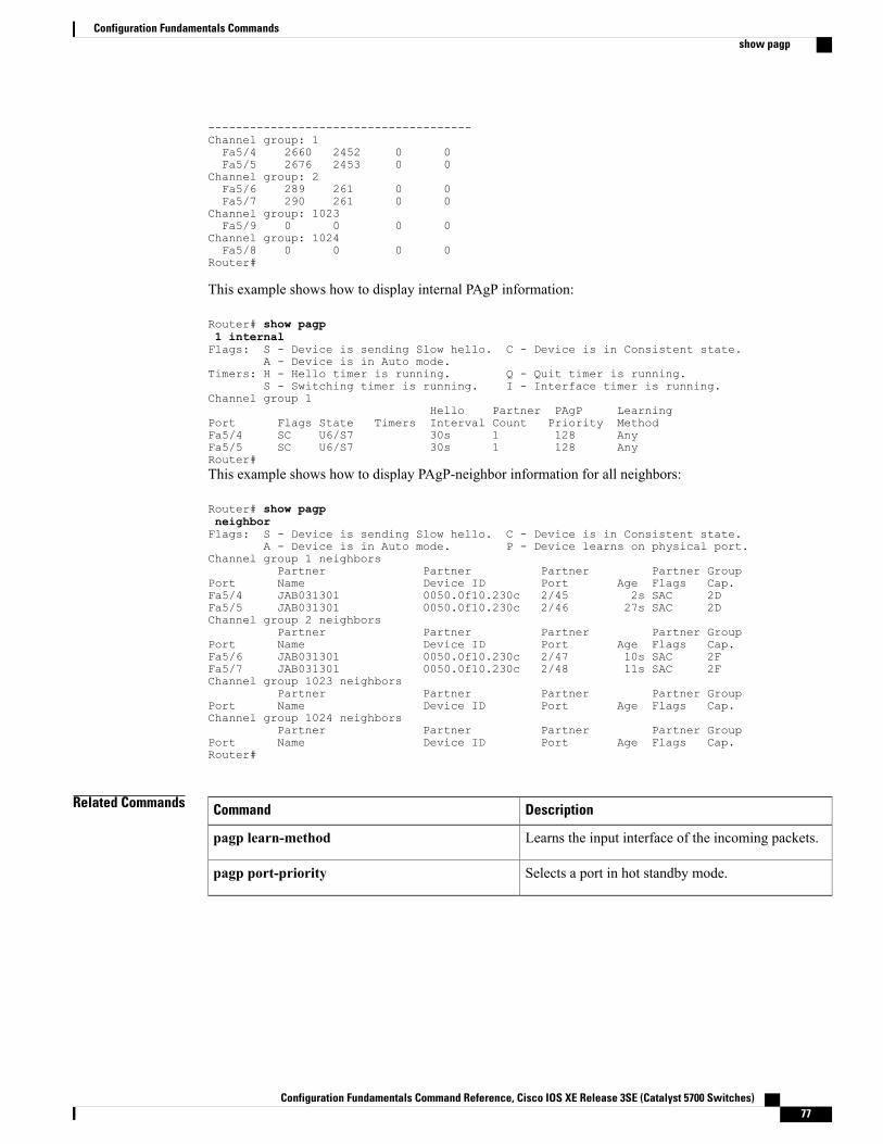
--------------------------------------Channel group: 1Fa5/4 2660 2452 0 0Fa5/5 2676 2453 0 0
Channel group: 2Fa5/6 289 261 0 0Fa5/7 290 261 0 0
Channel group: 1023Fa5/9 0 0 0 0
Channel group: 1024Fa5/8 0 0 0 0
Router#
This example shows how to display internal PAgP information:
Router# show pagp1 internalFlags: S - Device is sending Slow hello. C - Device is in Consistent state.
A - Device is in Auto mode.Timers: H - Hello timer is running. Q - Quit timer is running.
S - Switching timer is running. I - Interface timer is running.Channel group 1
Hello Partner PAgP LearningPort Flags State Timers Interval Count Priority MethodFa5/4 SC U6/S7 30s 1 128 AnyFa5/5 SC U6/S7 30s 1 128 AnyRouter#This example shows how to display PAgP-neighbor information for all neighbors:
Router# show pagpneighborFlags: S - Device is sending Slow hello. C - Device is in Consistent state.
A - Device is in Auto mode. P - Device learns on physical port.Channel group 1 neighbors
Partner Partner Partner Partner GroupPort Name Device ID Port Age Flags Cap.Fa5/4 JAB031301 0050.0f10.230c 2/45 2s SAC 2DFa5/5 JAB031301 0050.0f10.230c 2/46 27s SAC 2DChannel group 2 neighbors
Partner Partner Partner Partner GroupPort Name Device ID Port Age Flags Cap.Fa5/6 JAB031301 0050.0f10.230c 2/47 10s SAC 2FFa5/7 JAB031301 0050.0f10.230c 2/48 11s SAC 2FChannel group 1023 neighbors
Partner Partner Partner Partner GroupPort Name Device ID Port Age Flags Cap.Channel group 1024 neighbors
Partner Partner Partner Partner GroupPort Name Device ID Port Age Flags Cap.Router#
Related Commands DescriptionCommand
Learns the input interface of the incoming packets.pagp learn-method
Selects a port in hot standby mode.pagp port-priority
Configuration Fundamentals Command Reference, Cisco IOS XE Release 3SE (Catalyst 5700 Switches) 77
Configuration Fundamentals Commandsshow pagp
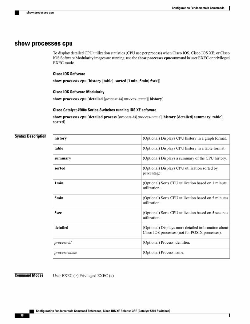
show processes cpuTo display detailed CPU utilization statistics (CPU use per process) when Cisco IOS, Cisco IOS XE, or CiscoIOS SoftwareModularity images are running, use the show processes cpucommand in user EXEC or privilegedEXEC mode.
Cisco IOS Software
show processes cpu [history [table]| sorted [1min| 5min| 5sec]]
Cisco IOS Software Modularity
show processes cpu [detailed [process-id| process-name]| history]
Cisco Catalyst 4500e Series Switches running IOS XE software
show processes cpu [detailed process [process-id| process-name]| history [detailed| summary| table]|sorted]
Syntax Description (Optional) Displays CPU history in a graph format.history
(Optional) Displays CPU history in a table format.table
(Optional) Displays a summary of the CPU history.summary
(Optional) Displays CPU utilization sorted bypercentage.
sorted
(Optional) Sorts CPU utilization based on 1 minuteutilization.
1min
(Optional) Sorts CPU utilization based on 5 minutesutilization.
5min
(Optional) Sorts CPU utilization based on 5 secondsutilization.
5sec
(Optional) Displays more detailed information aboutCisco IOS processes (not for POSIX processes).
detailed
(Optional) Process identifier.process-id
(Optional) Process name.process-name
Command Modes User EXEC (>) Privileged EXEC (#)
Configuration Fundamentals Command Reference, Cisco IOS XE Release 3SE (Catalyst 5700 Switches)78
Configuration Fundamentals Commandsshow processes cpu
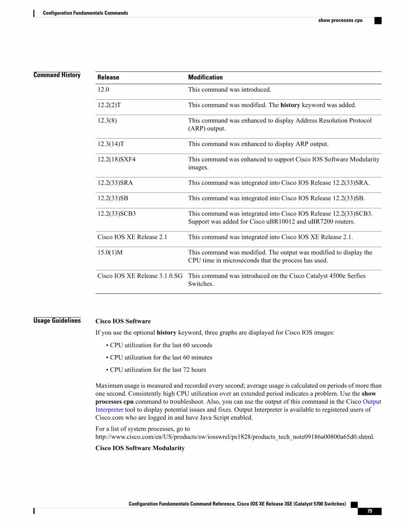
Command History ModificationRelease
This command was introduced.12.0
This command was modified. The history keyword was added.12.2(2)T
This command was enhanced to display Address Resolution Protocol(ARP) output.
12.3(8)
This command was enhanced to display ARP output.12.3(14)T
This command was enhanced to support Cisco IOS Software Modularityimages.
12.2(18)SXF4
This command was integrated into Cisco IOS Release 12.2(33)SRA.12.2(33)SRA
This command was integrated into Cisco IOS Release 12.2(33)SB.12.2(33)SB
This command was integrated into Cisco IOS Release 12.2(33)SCB3.Support was added for Cisco uBR10012 and uBR7200 routers.
12.2(33)SCB3
This command was integrated into Cisco IOS XE Release 2.1.Cisco IOS XE Release 2.1
This command was modified. The output was modified to display theCPU time in microseconds that the process has used.
15.0(1)M
This command was introduced on the Cisco Catalyst 4500e SerfiesSwitches.
Cisco IOS XE Release 3.1.0.SG
Usage Guidelines Cisco IOS Software
If you use the optional history keyword, three graphs are displayed for Cisco IOS images:
• CPU utilization for the last 60 seconds
• CPU utilization for the last 60 minutes
• CPU utilization for the last 72 hours
Maximum usage is measured and recorded every second; average usage is calculated on periods of more thanone second. Consistently high CPU utilization over an extended period indicates a problem. Use the showprocesses cpu command to troubleshoot. Also, you can use the output of this command in the Cisco OutputInterpreter tool to display potential issues and fixes. Output Interpreter is available to registered users ofCisco.com who are logged in and have Java Script enabled.
For a list of system processes, go tohttp://www.cisco.com/en/US/products/sw/iosswrel/ps1828/products_tech_note09186a00800a65d0.shtml.
Cisco IOS Software Modularity
Configuration Fundamentals Command Reference, Cisco IOS XE Release 3SE (Catalyst 5700 Switches) 79
Configuration Fundamentals Commandsshow processes cpu
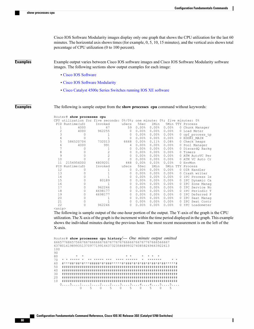
Cisco IOS Software Modularity images display only one graph that shows the CPU utilization for the last 60minutes. The horizontal axis shows times (for example, 0, 5, 10, 15 minutes), and the vertical axis shows totalpercentage of CPU utilization (0 to 100 percent).
Examples Example output varies between Cisco IOS software images and Cisco IOS Software Modularity softwareimages. The following sections show output examples for each image:
• Cisco IOS Software
• Cisco IOS Software Modularity
• Cisco Catalyst 4500e Series Switches running IOS XE software
Examples The following is sample output from the show processes cpu command without keywords:
Router# show processes cpuCPU utilization for five seconds: 0%/0%; one minute: 0%; five minutes: 0%PID Runtime(uS) Invoked uSecs 5Sec 1Min 5Min TTY Process1 4000 67 59 0.00% 0.00% 0.00% 0 Chunk Manager2 4000 962255 0 0.00% 0.00% 0.00% 0 Load Meter3 0 1 0 0.00% 0.00% 0.00% 0 cpf_process_tp4 0 1 0 0.00% 0.00% 0.00% 0 EDDRI_MAIN5 586520704 732013 6668 0.00% 0.11% 0.08% 0 Check heaps6 4000 991 4 0.00% 0.00% 0.00% 0 Pool Manager7 0 1 0 0.00% 0.00% 0.00% 0 DiscardQ Backg8 0 2 0 0.00% 0.00% 0.00% 0 Timers9 0 2 0 0.00% 0.00% 0.00% 0 ATM AutoVC Per10 0 2 0 0.00% 0.00% 0.00% 0 ATM VC Auto Cr11 2154956000 4809201 448 0.00% 0.03% 0.03% 0 EnvMonPID Runtime(uS) Invoked uSecs 5Sec 1Min 5Min TTY Process12 0 1 0 0.00% 0.00% 0.00% 0 OIR Handler13 0 1 0 0.00% 0.00% 0.00% 0 Crash writer14 0 1 0 0.00% 0.00% 0.00% 0 IPC Process le15 0 80189 0 0.00% 0.00% 0.00% 0 IPC Dynamic Ca16 0 1 0 0.00% 0.00% 0.00% 0 IPC Zone Manag17 0 962246 0 0.00% 0.00% 0.00% 0 IPC Service No18 0 4698177 0 0.00% 0.00% 0.00% 0 IPC Periodic T19 0 4698177 0 0.00% 0.00% 0.00% 0 IPC Deferred P20 0 1 0 0.00% 0.00% 0.00% 0 IPC Seat Manag21 0 1 0 0.00% 0.00% 0.00% 0 IPC Seat Contr22 0 962246 0 0.00% 0.00% 0.00% 0 IPC Loadometer
<snip>The following is sample output of the one-hour portion of the output. The Y-axis of the graph is the CPUutilization. The X-axis of the graph is the increment within the time period displayed in the graph. This exampleshows the individual minutes during the previous hour. The most recent measurement is on the left of theX-axis.
Router# show processes cpu history!--- One minute output omitted666577686575667667666666766767767676666676676776766656666763780161989935137097719914437323586899327408582696439226131009080 * * * * * * * *70 * * ***** * ** ***** *** **** ****** * ******* * *60 #***##*##*#***#####*#*###*****#*###*#*#*##*#*##*#*##*****#50 ##########################################################40 ##########################################################30 ##########################################################20 ##########################################################10 ##########################################################
0....5....1....1....2....2....3....3....4....4....5....5....0 5 0 5 0 5 0 5 0 5
Configuration Fundamentals Command Reference, Cisco IOS XE Release 3SE (Catalyst 5700 Switches)80
Configuration Fundamentals Commandsshow processes cpu
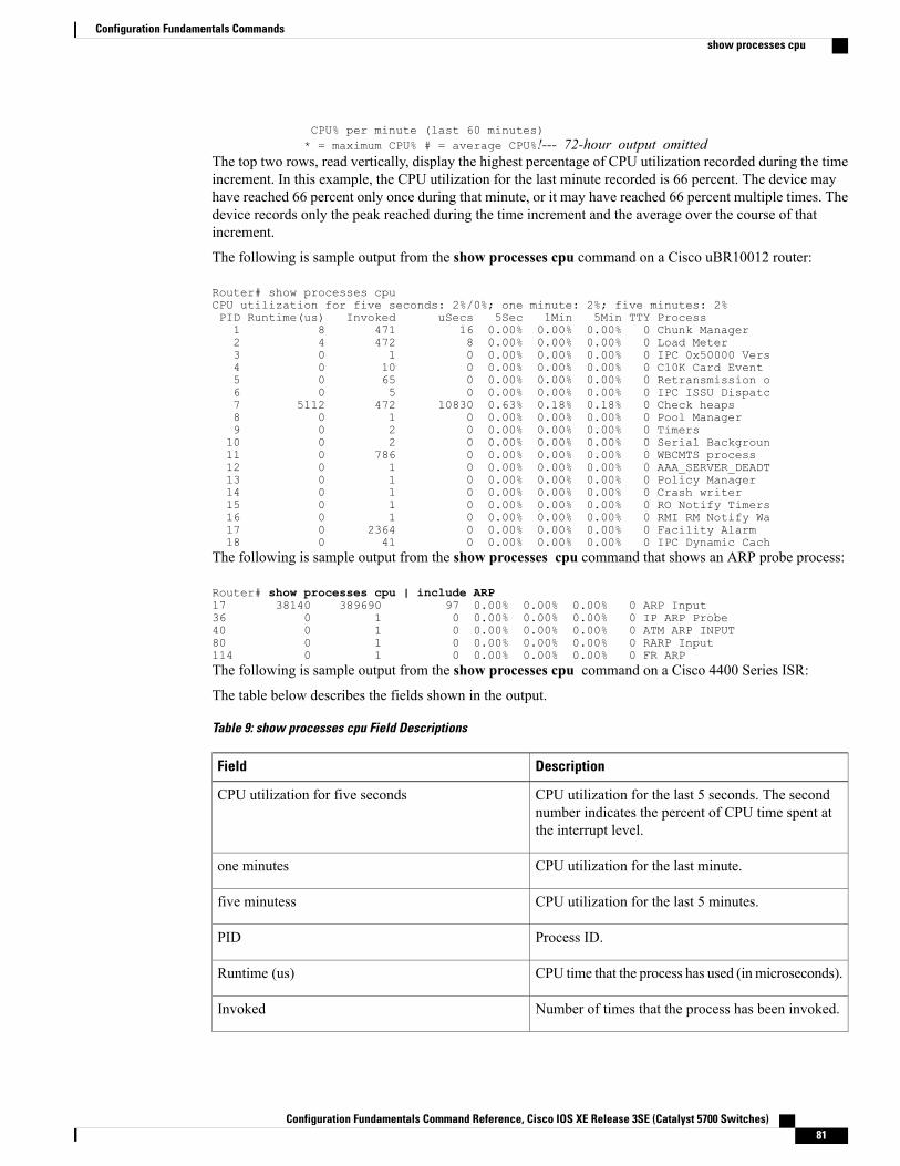
CPU% per minute (last 60 minutes)* = maximum CPU% # = average CPU%!--- 72-hour output omitted
The top two rows, read vertically, display the highest percentage of CPU utilization recorded during the timeincrement. In this example, the CPU utilization for the last minute recorded is 66 percent. The device mayhave reached 66 percent only once during that minute, or it may have reached 66 percent multiple times. Thedevice records only the peak reached during the time increment and the average over the course of thatincrement.
The following is sample output from the show processes cpu command on a Cisco uBR10012 router:
Router# show processes cpuCPU utilization for five seconds: 2%/0%; one minute: 2%; five minutes: 2%PID Runtime(us) Invoked uSecs 5Sec 1Min 5Min TTY Process1 8 471 16 0.00% 0.00% 0.00% 0 Chunk Manager2 4 472 8 0.00% 0.00% 0.00% 0 Load Meter3 0 1 0 0.00% 0.00% 0.00% 0 IPC 0x50000 Vers4 0 10 0 0.00% 0.00% 0.00% 0 C10K Card Event5 0 65 0 0.00% 0.00% 0.00% 0 Retransmission o6 0 5 0 0.00% 0.00% 0.00% 0 IPC ISSU Dispatc7 5112 472 10830 0.63% 0.18% 0.18% 0 Check heaps8 0 1 0 0.00% 0.00% 0.00% 0 Pool Manager9 0 2 0 0.00% 0.00% 0.00% 0 Timers10 0 2 0 0.00% 0.00% 0.00% 0 Serial Backgroun11 0 786 0 0.00% 0.00% 0.00% 0 WBCMTS process12 0 1 0 0.00% 0.00% 0.00% 0 AAA_SERVER_DEADT13 0 1 0 0.00% 0.00% 0.00% 0 Policy Manager14 0 1 0 0.00% 0.00% 0.00% 0 Crash writer15 0 1 0 0.00% 0.00% 0.00% 0 RO Notify Timers16 0 1 0 0.00% 0.00% 0.00% 0 RMI RM Notify Wa17 0 2364 0 0.00% 0.00% 0.00% 0 Facility Alarm18 0 41 0 0.00% 0.00% 0.00% 0 IPC Dynamic Cach
The following is sample output from the show processes cpu command that shows an ARP probe process:
Router# show processes cpu | include ARP17 38140 389690 97 0.00% 0.00% 0.00% 0 ARP Input36 0 1 0 0.00% 0.00% 0.00% 0 IP ARP Probe40 0 1 0 0.00% 0.00% 0.00% 0 ATM ARP INPUT80 0 1 0 0.00% 0.00% 0.00% 0 RARP Input114 0 1 0 0.00% 0.00% 0.00% 0 FR ARPThe following is sample output from the show processes cpu command on a Cisco 4400 Series ISR:
The table below describes the fields shown in the output.
Table 9: show processes cpu Field Descriptions
DescriptionField
CPU utilization for the last 5 seconds. The secondnumber indicates the percent of CPU time spent atthe interrupt level.
CPU utilization for five seconds
CPU utilization for the last minute.one minutes
CPU utilization for the last 5 minutes.five minutess
Process ID.PID
CPU time that the process has used (inmicroseconds).Runtime (us)
Number of times that the process has been invoked.Invoked
Configuration Fundamentals Command Reference, Cisco IOS XE Release 3SE (Catalyst 5700 Switches) 81
Configuration Fundamentals Commandsshow processes cpu
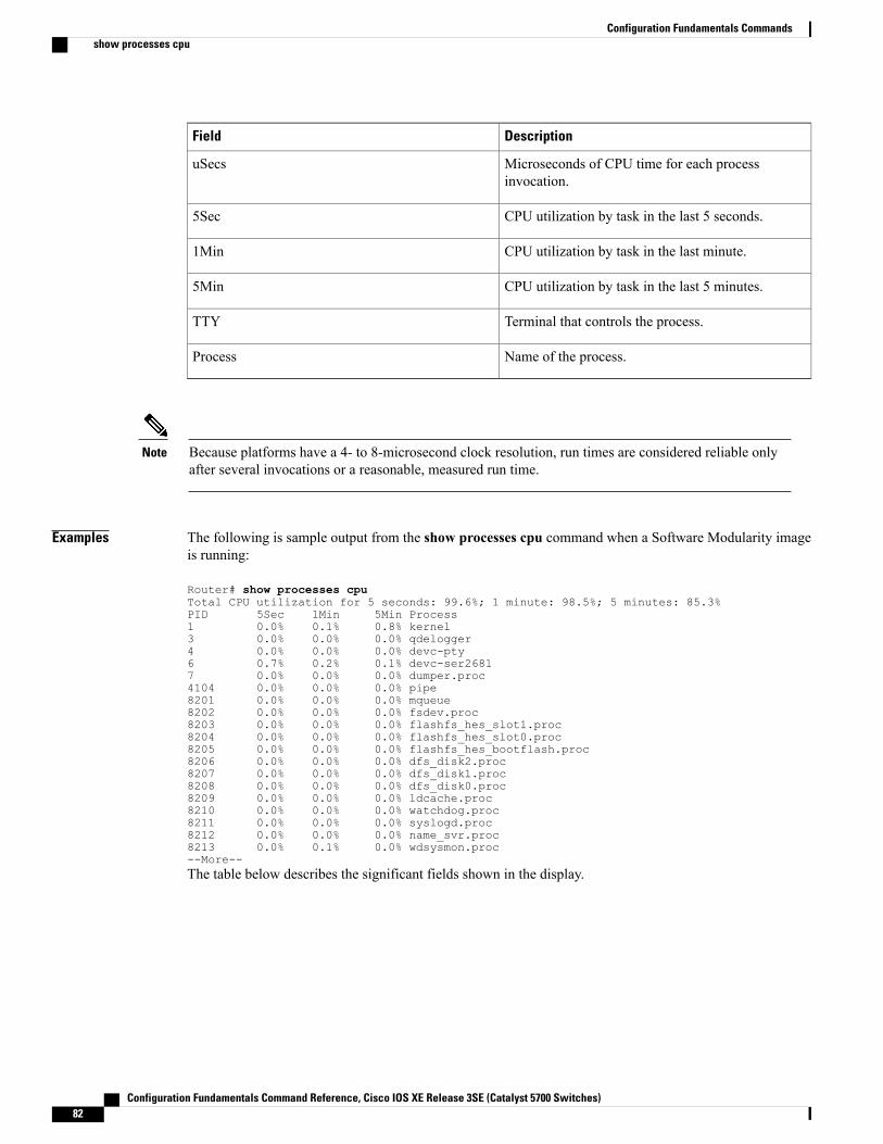
DescriptionField
Microseconds of CPU time for each processinvocation.
uSecs
CPU utilization by task in the last 5 seconds.5Sec
CPU utilization by task in the last minute.1Min
CPU utilization by task in the last 5 minutes.5Min
Terminal that controls the process.TTY
Name of the process.Process
Because platforms have a 4- to 8-microsecond clock resolution, run times are considered reliable onlyafter several invocations or a reasonable, measured run time.
Note
Examples The following is sample output from the show processes cpu command when a Software Modularity imageis running:
Router# show processes cpuTotal CPU utilization for 5 seconds: 99.6%; 1 minute: 98.5%; 5 minutes: 85.3%PID 5Sec 1Min 5Min Process1 0.0% 0.1% 0.8% kernel3 0.0% 0.0% 0.0% qdelogger4 0.0% 0.0% 0.0% devc-pty6 0.7% 0.2% 0.1% devc-ser26817 0.0% 0.0% 0.0% dumper.proc4104 0.0% 0.0% 0.0% pipe8201 0.0% 0.0% 0.0% mqueue8202 0.0% 0.0% 0.0% fsdev.proc8203 0.0% 0.0% 0.0% flashfs_hes_slot1.proc8204 0.0% 0.0% 0.0% flashfs_hes_slot0.proc8205 0.0% 0.0% 0.0% flashfs_hes_bootflash.proc8206 0.0% 0.0% 0.0% dfs_disk2.proc8207 0.0% 0.0% 0.0% dfs_disk1.proc8208 0.0% 0.0% 0.0% dfs_disk0.proc8209 0.0% 0.0% 0.0% ldcache.proc8210 0.0% 0.0% 0.0% watchdog.proc8211 0.0% 0.0% 0.0% syslogd.proc8212 0.0% 0.0% 0.0% name_svr.proc8213 0.0% 0.1% 0.0% wdsysmon.proc--More--The table below describes the significant fields shown in the display.
Configuration Fundamentals Command Reference, Cisco IOS XE Release 3SE (Catalyst 5700 Switches)82
Configuration Fundamentals Commandsshow processes cpu
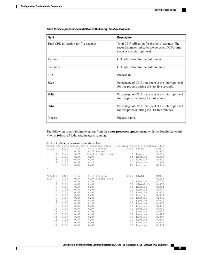
Table 10: show processes cpu (Software Modularity) Field Descriptions
DescriptionField
Total CPU utilization for the last 5 seconds. Thesecond number indicates the percent of CPU timespent at the interrupt level.
Total CPU utilization for five seconds
CPU utilization for the last minute.1 minute
CPU utilization for the last 5 minutes.5 minutes
Process ID.PID
Percentage of CPU time spent at the interrupt levelfor this process during the last five seconds.
5Sec
Percentage of CPU time spent at the interrupt levelfor this process during the last minute.
1Min
Percentage of CPU time spent at the interrupt levelfor this process during the last five minutes.
5Min
Process name.Process
The following is partial sample output from the show processes cpucommand with the detailedkeywordwhen a Software Modularity image is running:
Router# show processes cpu detailedTotal CPU utilization for 5 seconds: 99.6%; 1 minute: 99.3%; 5 minutes: 88.6%PID/TID 5Sec 1Min 5Min Process Prio STATE CPU1 0.0% 0.7% 0.7% kernel 8.900
1 0.4% 0.7% 11.4% [idle thread] 0 Ready 2m28s2 0.0% 0.0% 0.0% 63 Receive 0.0003 0.0% 0.0% 0.0% 10 Receive 0.0004 0.0% 0.0% 0.1% 11 Receive 1.8485 0.0% 0.0% 0.0% 63 Receive 0.000
.
.
.PID/TID 5Sec 1Min 5Min Process Prio STATE CPU8214 0.0% 0.0% 0.0% sysmgr.proc 0.216
1 0.0% 0.0% 0.0% 10 Receive 0.1322 0.0% 0.0% 0.0% 10 Sigwaitin 0.0003 0.0% 0.0% 0.0% 10 Receive 0.0044 0.0% 0.0% 0.0% 10 Receive 0.0005 0.0% 0.0% 0.0% 10 Receive 0.0006 0.0% 0.0% 0.0% 10 Receive 0.0047 0.0% 0.0% 0.0% 10 Receive 0.0008 0.0% 0.0% 0.0% 10 Receive 0.0009 0.0% 0.0% 0.0% 10 Receive 0.00010 0.0% 0.0% 0.0% 10 Receive 0.00011 0.0% 0.0% 0.0% 10 Receive 0.00012 0.0% 0.0% 0.0% 10 Receive 0.00013 0.0% 0.0% 0.0% 10 Receive 0.02814 0.0% 0.0% 0.0% 10 Receive 0.04015 0.0% 0.0% 0.0% 10 Receive 0.00016 0.0% 0.0% 0.0% 10 Receive 0.00017 0.0% 0.0% 0.0% 10 Receive 0.004
Configuration Fundamentals Command Reference, Cisco IOS XE Release 3SE (Catalyst 5700 Switches) 83
Configuration Fundamentals Commandsshow processes cpu
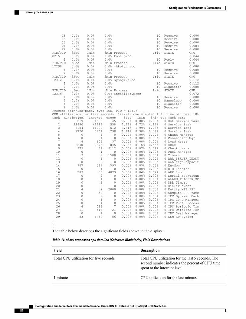
18 0.0% 0.0% 0.0% 10 Receive 0.00019 0.0% 0.0% 0.0% 10 Receive 0.00020 0.0% 0.0% 0.0% 10 Receive 0.00021 0.0% 0.0% 0.0% 10 Receive 0.00422 0.0% 0.0% 0.0% 10 Receive 0.000
PID/TID 5Sec 1Min 5Min Process Prio STATE CPU8215 0.0% 0.0% 0.0% kosh.proc 0.044
1 0.0% 0.0% 0.0% 10 Reply 0.044PID/TID 5Sec 1Min 5Min Process Prio STATE CPU12290 0.0% 0.0% 0.0% chkptd.proc 0.080
1 0.0% 0.0% 0.0% 10 Receive 0.0802 0.0% 0.0% 0.0% 10 Receive 0.000
PID/TID 5Sec 1Min 5Min Process Prio STATE CPU12312 0.0% 0.0% 0.0% sysmgr.proc 0.112
1 0.0% 0.0% 0.0% 10 Receive 0.1122 0.0% 0.0% 0.0% 10 Sigwaitin 0.000
PID/TID 5Sec 1Min 5Min Process Prio STATE CPU12316 0.0% 0.0% 0.0% installer.proc 0.072
1 0.0% 0.0% 0.0% 10 Receive 0.0003 0.0% 0.0% 0.0% 10 Nanosleep 0.0004 0.0% 0.0% 0.0% 10 Sigwaitin 0.0006 0.0% 0.0% 0.0% 10 Receive 0.000
Process sbin/ios-base, type IOS, PID = 12317CPU utilization for five seconds: 12%/9%; one minute: 13%; five minutes: 10%Task Runtime(us) Invoked uSecs 5Sec 1Min 5Min TTY Task Name
1 219 1503 145 0.00% 0.00% 0.00% 0 Hot Service Task2 23680 42384 558 2.39% 6.72% 4.81% 0 Service Task3 6104 11902 512 3.51% 1.99% 1.23% 0 Service Task4 1720 5761 298 1.91% 0.90% 0.39% 0 Service Task5 0 5 0 0.00% 0.00% 0.00% 0 Chunk Manager6 0 1 0 0.00% 0.00% 0.00% 0 Connection Mgr7 4 106 37 0.00% 0.00% 0.00% 0 Load Meter8 6240 7376 845 0.23% 0.15% 0.55% 0 Exec9 379 62 6112 0.00% 0.07% 0.04% 0 Check heaps10 0 1 0 0.00% 0.00% 0.00% 0 Pool Manager11 3 2 1500 0.00% 0.00% 0.00% 0 Timers12 0 1 0 0.00% 0.00% 0.00% 0 AAA_SERVER_DEADT13 0 2 0 0.00% 0.00% 0.00% 0 AAA high-capacit14 307 517 593 0.00% 0.05% 0.03% 0 EnvMon15 0 1 0 0.00% 0.00% 0.00% 0 OIR Handler16 283 58 4879 0.00% 0.04% 0.02% 0 ARP Input17 0 2 0 0.00% 0.00% 0.00% 0 Serial Backgroun18 0 81 0 0.00% 0.00% 0.00% 0 ALARM_TRIGGER_SC19 0 2 0 0.00% 0.00% 0.00% 0 DDR Timers20 0 2 0 0.00% 0.00% 0.00% 0 Dialer event21 4 2 2000 0.00% 0.00% 0.00% 0 Entity MIB API22 0 54 0 0.00% 0.00% 0.00% 0 Compute SRP rate23 0 9 0 0.00% 0.00% 0.00% 0 IPC Dynamic Cach24 0 1 0 0.00% 0.00% 0.00% 0 IPC Zone Manager25 0 1 0 0.00% 0.00% 0.00% 0 IPC Punt Process26 4 513 7 0.00% 0.00% 0.00% 0 IPC Periodic Tim27 11 513 21 0.00% 0.00% 0.00% 0 IPC Deferred Por28 0 1 0 0.00% 0.00% 0.00% 0 IPC Seat Manager29 83 1464 56 0.00% 0.00% 0.00% 0 EEM ED Syslog
.
.
.The table below describes the significant fields shown in the display.
Table 11: show processes cpu detailed (Software Modularity) Field Descriptions
DescriptionField
Total CPU utilization for the last 5 seconds. Thesecond number indicates the percent of CPU timespent at the interrupt level.
Total CPU utilization for five seconds
CPU utilization for the last minute.1 minute
Configuration Fundamentals Command Reference, Cisco IOS XE Release 3SE (Catalyst 5700 Switches)84
Configuration Fundamentals Commandsshow processes cpu
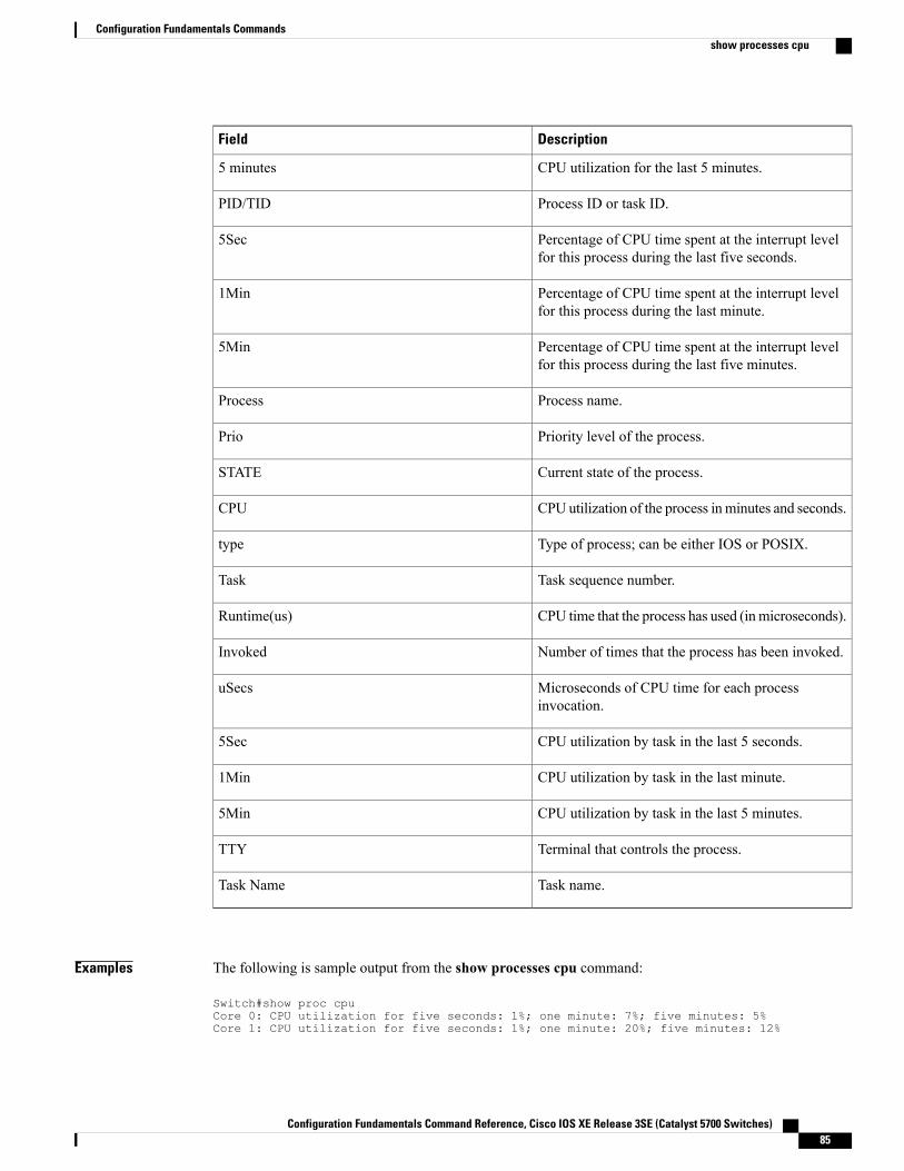
DescriptionField
CPU utilization for the last 5 minutes.5 minutes
Process ID or task ID.PID/TID
Percentage of CPU time spent at the interrupt levelfor this process during the last five seconds.
5Sec
Percentage of CPU time spent at the interrupt levelfor this process during the last minute.
1Min
Percentage of CPU time spent at the interrupt levelfor this process during the last five minutes.
5Min
Process name.Process
Priority level of the process.Prio
Current state of the process.STATE
CPU utilization of the process inminutes and seconds.CPU
Type of process; can be either IOS or POSIX.type
Task sequence number.Task
CPU time that the process has used (inmicroseconds).Runtime(us)
Number of times that the process has been invoked.Invoked
Microseconds of CPU time for each processinvocation.
uSecs
CPU utilization by task in the last 5 seconds.5Sec
CPU utilization by task in the last minute.1Min
CPU utilization by task in the last 5 minutes.5Min
Terminal that controls the process.TTY
Task name.Task Name
Examples The following is sample output from the show processes cpu command:
Switch#show proc cpuCore 0: CPU utilization for five seconds: 1%; one minute: 7%; five minutes: 5%Core 1: CPU utilization for five seconds: 1%; one minute: 20%; five minutes: 12%
Configuration Fundamentals Command Reference, Cisco IOS XE Release 3SE (Catalyst 5700 Switches) 85
Configuration Fundamentals Commandsshow processes cpu
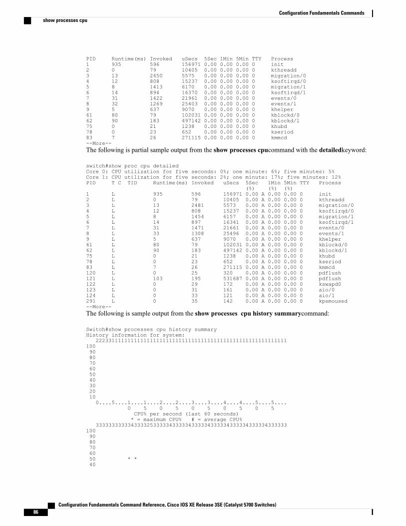
PID Runtime(ms) Invoked uSecs 5Sec 1Min 5Min TTY Process1 935 596 156971 0.00 0.00 0.00 0 init2 0 79 10405 0.00 0.00 0.00 0 kthreadd3 13 2450 5575 0.00 0.00 0.00 0 migration/04 12 808 15237 0.00 0.00 0.00 0 ksoftirqd/05 8 1413 6170 0.00 0.00 0.00 0 migration/16 14 894 16370 0.00 0.00 0.00 0 ksoftirqd/17 31 1422 21961 0.00 0.00 0.00 0 events/08 32 1269 25403 0.00 0.00 0.00 0 events/19 5 637 9070 0.00 0.00 0.00 0 khelper61 80 79 102031 0.00 0.00 0.00 0 kblockd/062 90 183 497142 0.00 0.00 0.00 0 kblockd/175 0 21 1238 0.00 0.00 0.00 0 khubd78 0 23 652 0.00 0.00 0.00 0 kseriod83 7 26 271115 0.00 0.00 0.00 0 kmmcd--More--The following is partial sample output from the show processes cpucommand with the detailedkeyword:
switch#show proc cpu detailedCore 0: CPU utilization for five seconds: 0%; one minute: 6%; five minutes: 5%Core 1: CPU utilization for five seconds: 2%; one minute: 17%; five minutes: 12%PID T C TID Runtime(ms) Invoked uSecs 5Sec 1Min 5Min TTY Process
(%) (%) (%)1 L 935 596 156971 0.00 A 0.00 0.00 0 init2 L 0 79 10405 0.00 A 0.00 0.00 0 kthreadd3 L 13 2481 5573 0.00 A 0.00 0.00 0 migration/04 L 12 808 15237 0.00 A 0.00 0.00 0 ksoftirqd/05 L 8 1454 6157 0.00 A 0.00 0.00 0 migration/16 L 14 897 16341 0.00 A 0.00 0.00 0 ksoftirqd/17 L 31 1471 21661 0.00 A 0.00 0.00 0 events/08 L 33 1308 25496 0.00 A 0.00 0.00 0 events/19 L 5 637 9070 0.00 A 0.00 0.00 0 khelper61 L 80 79 102031 0.00 A 0.00 0.00 0 kblockd/062 L 90 183 497142 0.00 A 0.00 0.00 0 kblockd/175 L 0 21 1238 0.00 A 0.00 0.00 0 khubd78 L 0 23 652 0.00 A 0.00 0.00 0 kseriod83 L 7 26 271115 0.00 A 0.00 0.00 0 kmmcd120 L 0 25 320 0.00 A 0.00 0.00 0 pdflush121 L 103 195 531687 0.00 A 0.00 0.00 0 pdflush122 L 0 29 172 0.00 A 0.00 0.00 0 kswapd0123 L 0 31 161 0.00 A 0.00 0.00 0 aio/0124 L 0 33 121 0.00 A 0.00 0.00 0 aio/1291 L 0 35 142 0.00 A 0.00 0.00 0 kpsmoused--More--The following is sample output from the show processes cpu history summarycommand:
Switch#show processes cpu history summaryHistory information for system:
2223311111111111111111111111111111111111111111111111111111111009080706050403020100....5....1....1....2....2....3....3....4....4....5....5....
0 5 0 5 0 5 0 5 0 5CPU% per second (last 60 seconds)* = maximum CPU% # = average CPU%
3333333333343333253333343333343333343333343333343333343333331009080706050 * *40
Configuration Fundamentals Command Reference, Cisco IOS XE Release 3SE (Catalyst 5700 Switches)86
Configuration Fundamentals Commandsshow processes cpu
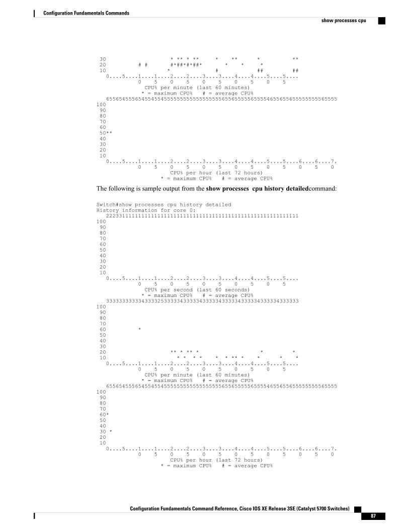
30 * ** * ** * ** * **20 # # #*##*#*##* * * *10 * # ## ##0....5....1....1....2....2....3....3....4....4....5....5....
0 5 0 5 0 5 0 5 0 5CPU% per minute (last 60 minutes)* = maximum CPU% # = average CPU%
6556545556545545545555555555555555556556555556555546556556555555555655551009080706050**403020100....5....1....1....2....2....3....3....4....4....5....5....6....6....7.
0 5 0 5 0 5 0 5 0 5 0 5 0CPU% per hour (last 72 hours)
* = maximum CPU% # = average CPU%
The following is sample output from the show processes cpu history detailedcommand:
Switch#show processes cpu history detailedHistory information for core 0:
2223311111111111111111111111111111111111111111111111111111111009080706050403020100....5....1....1....2....2....3....3....4....4....5....5....
0 5 0 5 0 5 0 5 0 5CPU% per second (last 60 seconds)* = maximum CPU% # = average CPU%
33333333333433332533333433333433333433333433333433333433333310090807060 *50403020 ** * ** * * *10 * * * * * * ** * * * *0....5....1....1....2....2....3....3....4....4....5....5....
0 5 0 5 0 5 0 5 0 5CPU% per minute (last 60 minutes)* = maximum CPU% # = average CPU%
65565455565455455455555555555555555565565555565555465565565555555556555510090807060*504030 *20100....5....1....1....2....2....3....3....4....4....5....5....6....6....7.
0 5 0 5 0 5 0 5 0 5 0 5 0CPU% per hour (last 72 hours)
* = maximum CPU% # = average CPU%
Configuration Fundamentals Command Reference, Cisco IOS XE Release 3SE (Catalyst 5700 Switches) 87
Configuration Fundamentals Commandsshow processes cpu
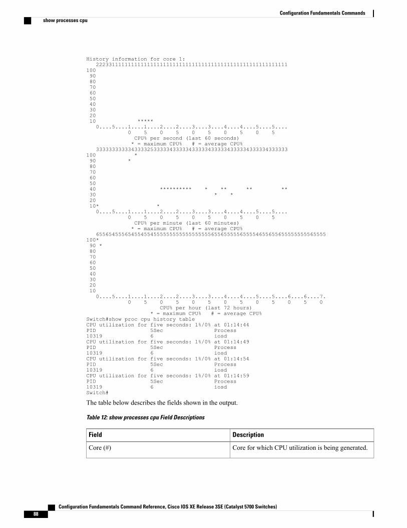
History information for core 1:222331111111111111111111111111111111111111111111111111111111
100908070605040302010 *****0....5....1....1....2....2....3....3....4....4....5....5....
0 5 0 5 0 5 0 5 0 5CPU% per second (last 60 seconds)* = maximum CPU% # = average CPU%
333333333334333325333334333334333334333334333334333334333333100 *90 *8070605040 ********** * ** ** **30 * *2010* *0....5....1....1....2....2....3....3....4....4....5....5....
0 5 0 5 0 5 0 5 0 5CPU% per minute (last 60 minutes)* = maximum CPU% # = average CPU%
655654555654554554555555555555555555655655555655554655655655555555565555100*90 *80706050403020100....5....1....1....2....2....3....3....4....4....5....5....6....6....7.
0 5 0 5 0 5 0 5 0 5 0 5 0CPU% per hour (last 72 hours)
* = maximum CPU% # = average CPU%Switch#show proc cpu history tableCPU utilization for five seconds: 1%/0% at 01:14:44PID 5Sec Process10319 6 iosdCPU utilization for five seconds: 1%/0% at 01:14:49PID 5Sec Process10319 6 iosdCPU utilization for five seconds: 1%/0% at 01:14:54PID 5Sec Process10319 6 iosdCPU utilization for five seconds: 1%/0% at 01:14:59PID 5Sec Process10319 6 iosdSwitch#
The table below describes the fields shown in the output.
Table 12: show processes cpu Field Descriptions
DescriptionField
Core for which CPU utilization is being generated.Core (#)
Configuration Fundamentals Command Reference, Cisco IOS XE Release 3SE (Catalyst 5700 Switches)88
Configuration Fundamentals Commandsshow processes cpu
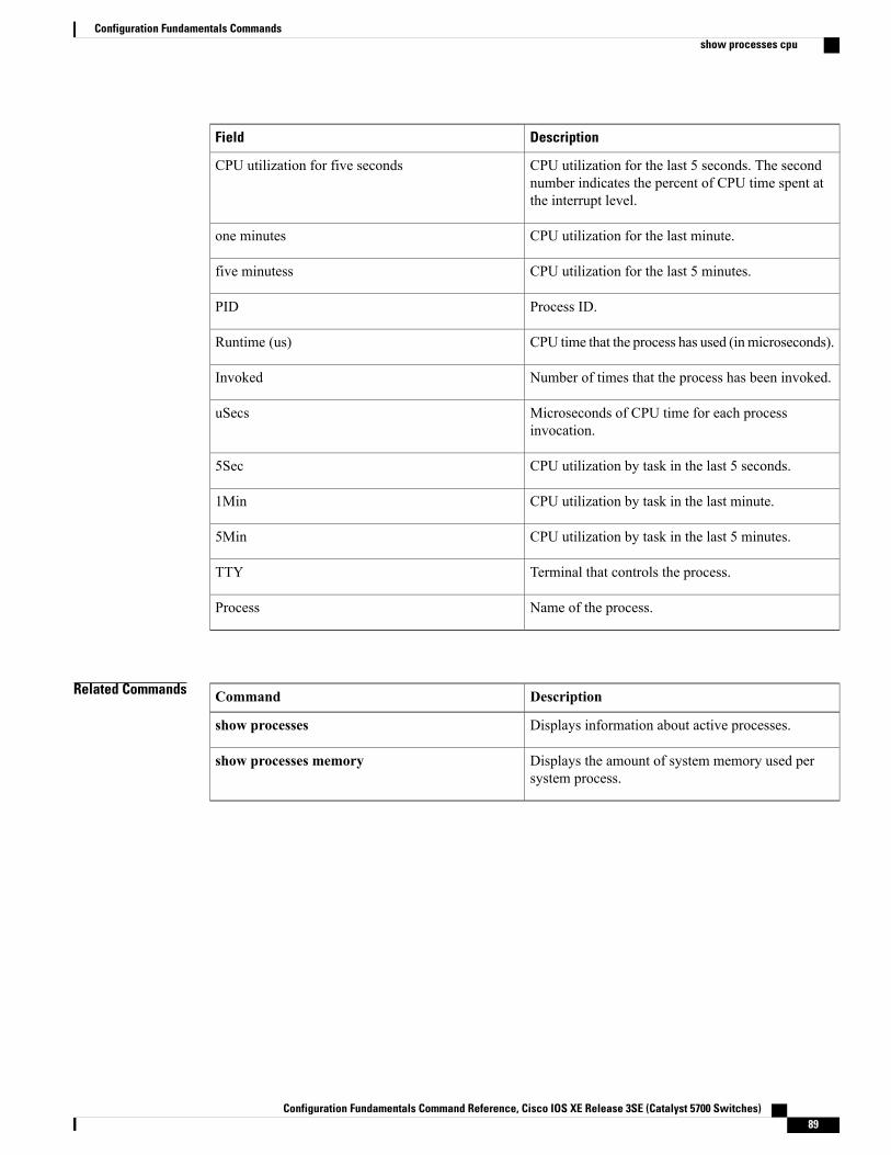
DescriptionField
CPU utilization for the last 5 seconds. The secondnumber indicates the percent of CPU time spent atthe interrupt level.
CPU utilization for five seconds
CPU utilization for the last minute.one minutes
CPU utilization for the last 5 minutes.five minutess
Process ID.PID
CPU time that the process has used (inmicroseconds).Runtime (us)
Number of times that the process has been invoked.Invoked
Microseconds of CPU time for each processinvocation.
uSecs
CPU utilization by task in the last 5 seconds.5Sec
CPU utilization by task in the last minute.1Min
CPU utilization by task in the last 5 minutes.5Min
Terminal that controls the process.TTY
Name of the process.Process
Related Commands DescriptionCommand
Displays information about active processes.show processes
Displays the amount of system memory used persystem process.
show processes memory
Configuration Fundamentals Command Reference, Cisco IOS XE Release 3SE (Catalyst 5700 Switches) 89
Configuration Fundamentals Commandsshow processes cpu
show running-configTo display the contents of the current running configuration file or the configuration for a specific module,Layer 2 VLAN, class map, interface, map class, policy map, or virtual circuit (VC) class, use the showrunning-config command in privileged EXEC mode.
show running-config [ options ]
Configuration Fundamentals Command Reference, Cisco IOS XE Release 3SE (Catalyst 5700 Switches)90
Configuration Fundamentals Commandsshow running-config
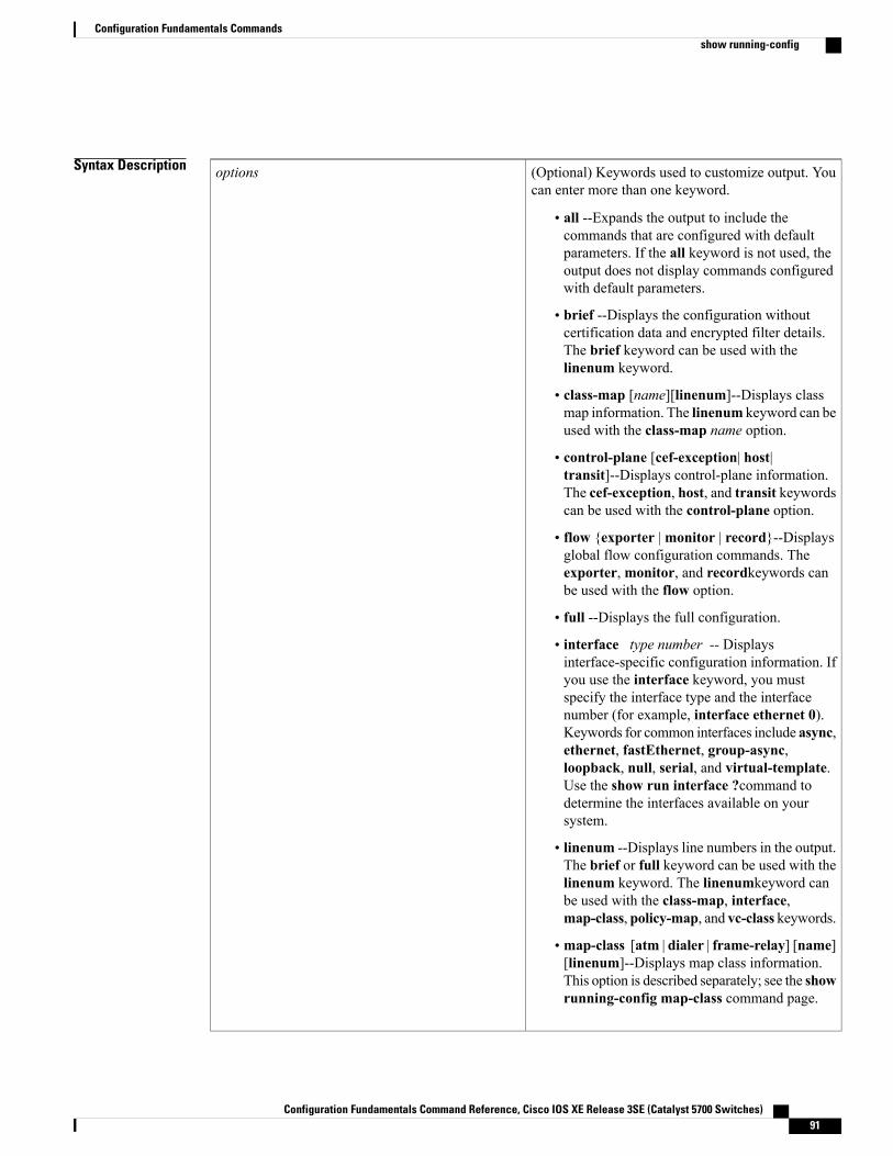
Syntax Description (Optional) Keywords used to customize output. Youcan enter more than one keyword.
• all --Expands the output to include thecommands that are configured with defaultparameters. If the all keyword is not used, theoutput does not display commands configuredwith default parameters.
• brief --Displays the configuration withoutcertification data and encrypted filter details.The brief keyword can be used with thelinenum keyword.
• class-map [name][linenum]--Displays classmap information. The linenum keyword can beused with the class-map name option.
• control-plane [cef-exception| host|transit]--Displays control-plane information.The cef-exception, host, and transit keywordscan be used with the control-plane option.
• flow {exporter |monitor | record}--Displaysglobal flow configuration commands. Theexporter, monitor, and recordkeywords canbe used with the flow option.
• full --Displays the full configuration.
• interface type number -- Displaysinterface-specific configuration information. Ifyou use the interface keyword, you mustspecify the interface type and the interfacenumber (for example, interface ethernet 0).Keywords for common interfaces include async,ethernet, fastEthernet, group-async,loopback, null, serial, and virtual-template.Use the show run interface ?command todetermine the interfaces available on yoursystem.
• linenum --Displays line numbers in the output.The brief or full keyword can be used with thelinenum keyword. The linenumkeyword canbe used with the class-map, interface,map-class, policy-map, and vc-class keywords.
• map-class [atm | dialer | frame-relay] [name][linenum]--Displays map class information.This option is described separately; see the showrunning-config map-class command page.
options
Configuration Fundamentals Command Reference, Cisco IOS XE Release 3SE (Catalyst 5700 Switches) 91
Configuration Fundamentals Commandsshow running-config
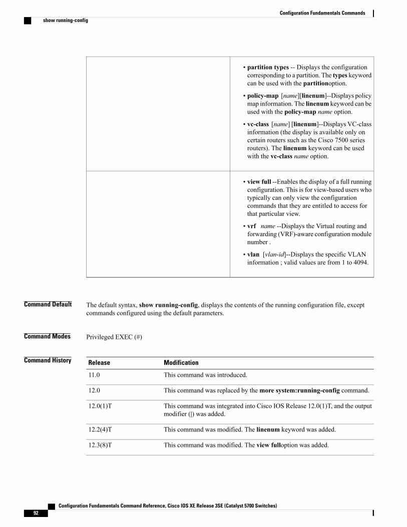
• partition types -- Displays the configurationcorresponding to a partition. The types keywordcan be used with the partitionoption.
• policy-map [name][linenum]--Displays policymap information. The linenum keyword can beused with the policy-map name option.
• vc-class [name] [linenum]--Displays VC-classinformation (the display is available only oncertain routers such as the Cisco 7500 seriesrouters). The linenum keyword can be usedwith the vc-class name option.
• view full --Enables the display of a full runningconfiguration. This is for view-based users whotypically can only view the configurationcommands that they are entitled to access forthat particular view.
• vrf name --Displays the Virtual routing andforwarding (VRF)-aware configuration modulenumber .
• vlan [vlan-id]--Displays the specific VLANinformation ; valid values are from 1 to 4094.
Command Default The default syntax, show running-config, displays the contents of the running configuration file, exceptcommands configured using the default parameters.
Command Modes Privileged EXEC (#)
Command History ModificationRelease
This command was introduced.11.0
This command was replaced by themore system:running-config command.12.0
This command was integrated into Cisco IOS Release 12.0(1)T, and the outputmodifier (|) was added.
12.0(1)T
This command was modified. The linenum keyword was added.12.2(4)T
This command was modified. The view fulloption was added.12.3(8)T
Configuration Fundamentals Command Reference, Cisco IOS XE Release 3SE (Catalyst 5700 Switches)92
Configuration Fundamentals Commandsshow running-config
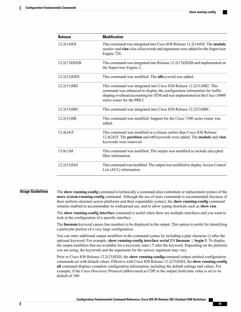
ModificationRelease
This command was integrated into Cisco IOS Release 12.2(14)SX. Themodulenumber and vlan vlan-id keywords and arguments were added for the SupervisorEngine 720.
12.2(14)SX
This command was integrated into Release 12.2(17d)SXB and implemented onthe Supervisor Engine 2.
12.2(17d)SXB
This command was modified. The allkeyword was added.12.2(33)SXH
This command was integrated into Cisco IOS Release 12.2(31)SB2. Thiscommand was enhanced to display the configuration information for trafficshaping overhead accounting for ATM andwas implemented on the Cisco 10000series router for the PRE3.
12.2(31)SB2
This command was integrated into Cisco IOS Release 12.2(33)SRC.12.2(33)SRC
This command was modified. Support for the Cisco 7300 series router wasadded.
12.2(33)SB
This command was modified in a release earlier than Cisco IOS Release12.4(24)T. The partition and vrf keywords were added. Themodule and vlankeywords were removed.
12.4(24)T
This command was modified. The output was modified to include encryptedfilter information.
15.0(1)M
This commandwasmodified. The output wasmodified to displayAccess ControlList (ACL) information.
12.2(33)SXI
Usage Guidelines The show running-config command is technically a command alias (substitute or replacement syntax) of themore system:running-config command. Although the use of more commands is recommended (because oftheir uniform structure across platforms and their expandable syntax), the show running-config commandremains enabled to accommodate its widespread use, and to allow typing shortcuts such as show run.
The show running-config interface command is useful when there are multiple interfaces and you want tolook at the configuration of a specific interface.
The linenum keyword causes line numbers to be displayed in the output. This option is useful for identifyinga particular portion of a very large configuration.
You can enter additional output modifiers in the command syntax by including a pipe character (|) after theoptional keyword. For example, show running-config interface serial 2/1 linenum | begin 3. To displaythe output modifiers that are available for a keyword, enter | ? after the keyword. Depending on the platformyou are using, the keywords and the arguments for the options argument may vary.
Prior to Cisco IOS Release 12.2(33)SXH, the show running-configcommand output omitted configurationcommands set with default values. Effective with Cisco IOS Release 12.2(33)SXH, the show running-configall command displays complete configuration information, including the default settings and values. Forexample, if the Cisco Discovery Protocol (abbreviated as CDP in the output) hold-time value is set to itsdefault of 180:
Configuration Fundamentals Command Reference, Cisco IOS XE Release 3SE (Catalyst 5700 Switches) 93
Configuration Fundamentals Commandsshow running-config
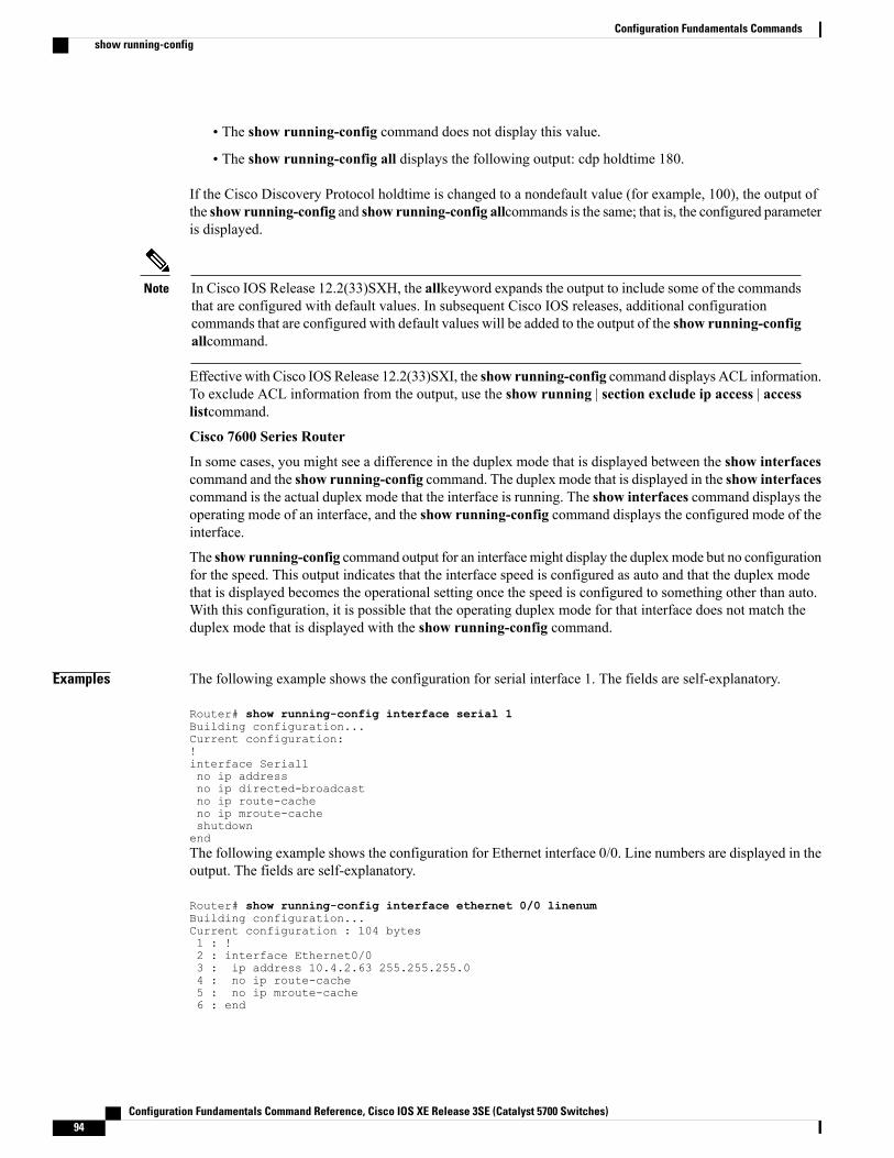
• The show running-config command does not display this value.
• The show running-config all displays the following output: cdp holdtime 180.
If the Cisco Discovery Protocol holdtime is changed to a nondefault value (for example, 100), the output ofthe show running-config and show running-config allcommands is the same; that is, the configured parameteris displayed.
In Cisco IOS Release 12.2(33)SXH, the allkeyword expands the output to include some of the commandsthat are configured with default values. In subsequent Cisco IOS releases, additional configurationcommands that are configured with default values will be added to the output of the show running-configallcommand.
Note
Effective with Cisco IOSRelease 12.2(33)SXI, the show running-config command displays ACL information.To exclude ACL information from the output, use the show running | section exclude ip access | accesslistcommand.
Cisco 7600 Series Router
In some cases, you might see a difference in the duplex mode that is displayed between the show interfacescommand and the show running-config command. The duplex mode that is displayed in the show interfacescommand is the actual duplex mode that the interface is running. The show interfaces command displays theoperating mode of an interface, and the show running-config command displays the configured mode of theinterface.
The show running-config command output for an interfacemight display the duplexmode but no configurationfor the speed. This output indicates that the interface speed is configured as auto and that the duplex modethat is displayed becomes the operational setting once the speed is configured to something other than auto.With this configuration, it is possible that the operating duplex mode for that interface does not match theduplex mode that is displayed with the show running-config command.
Examples The following example shows the configuration for serial interface 1. The fields are self-explanatory.
Router# show running-config interface serial 1Building configuration...Current configuration:!interface Serial1no ip addressno ip directed-broadcastno ip route-cacheno ip mroute-cacheshutdownendThe following example shows the configuration for Ethernet interface 0/0. Line numbers are displayed in theoutput. The fields are self-explanatory.
Router# show running-config interface ethernet 0/0 linenumBuilding configuration...Current configuration : 104 bytes1 : !2 : interface Ethernet0/03 : ip address 10.4.2.63 255.255.255.04 : no ip route-cache5 : no ip mroute-cache6 : end
Configuration Fundamentals Command Reference, Cisco IOS XE Release 3SE (Catalyst 5700 Switches)94
Configuration Fundamentals Commandsshow running-config
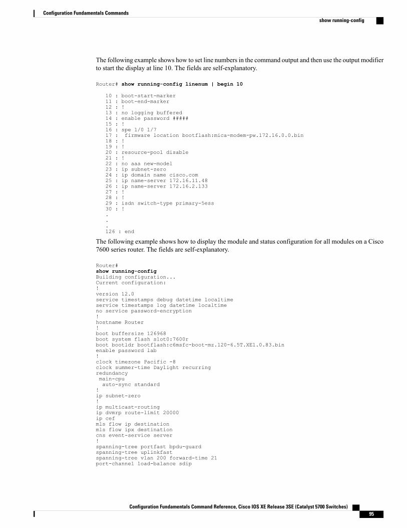
The following example shows how to set line numbers in the command output and then use the output modifierto start the display at line 10. The fields are self-explanatory.
Router# show running-config linenum | begin 10
10 : boot-start-marker11 : boot-end-marker12 : !13 : no logging buffered14 : enable password #####15 : !16 : spe 1/0 1/717 : firmware location bootflash:mica-modem-pw.172.16.0.0.bin18 : !19 : !20 : resource-pool disable21 : !22 : no aaa new-model23 : ip subnet-zero24 : ip domain name cisco.com25 : ip name-server 172.16.11.4826 : ip name-server 172.16.2.13327 : !28 : !29 : isdn switch-type primary-5ess30 : !...126 : end
The following example shows how to display the module and status configuration for all modules on a Cisco7600 series router. The fields are self-explanatory.
Router#show running-configBuilding configuration...Current configuration:!version 12.0service timestamps debug datetime localtimeservice timestamps log datetime localtimeno service password-encryption!hostname Router!boot buffersize 126968boot system flash slot0:7600rboot bootldr bootflash:c6msfc-boot-mz.120-6.5T.XE1.0.83.binenable password lab!clock timezone Pacific -8clock summer-time Daylight recurringredundancymain-cpuauto-sync standard
!ip subnet-zero!ip multicast-routingip dvmrp route-limit 20000ip cefmls flow ip destinationmls flow ipx destinationcns event-service server!spanning-tree portfast bpdu-guardspanning-tree uplinkfastspanning-tree vlan 200 forward-time 21port-channel load-balance sdip
Configuration Fundamentals Command Reference, Cisco IOS XE Release 3SE (Catalyst 5700 Switches) 95
Configuration Fundamentals Commandsshow running-config
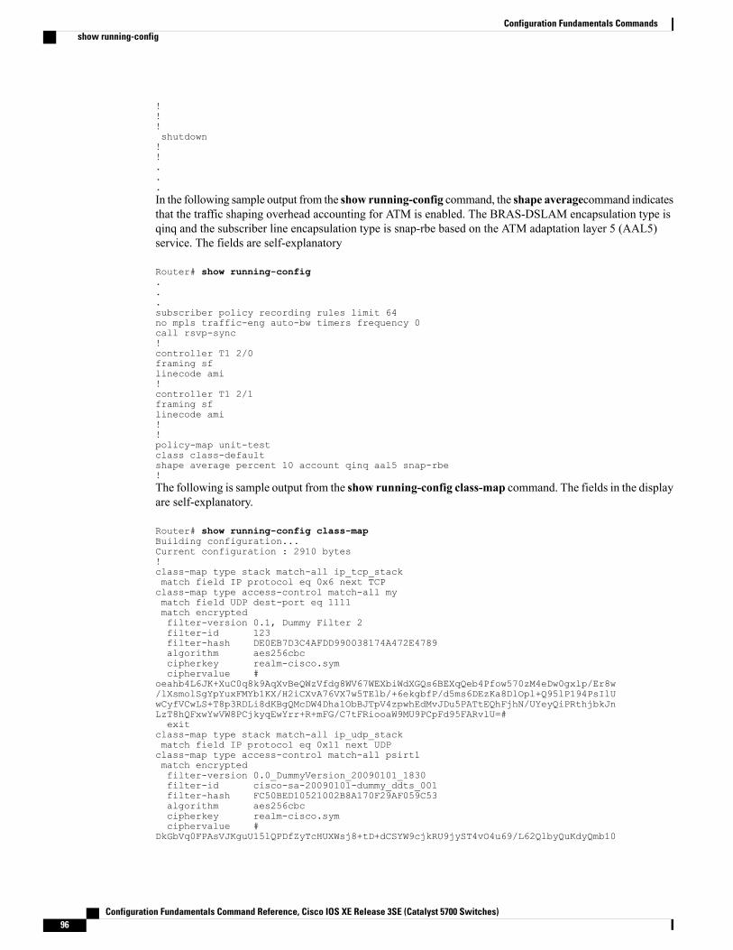
!!!shutdown!!...In the following sample output from the show running-config command, the shape averagecommand indicatesthat the traffic shaping overhead accounting for ATM is enabled. The BRAS-DSLAM encapsulation type isqinq and the subscriber line encapsulation type is snap-rbe based on the ATM adaptation layer 5 (AAL5)service. The fields are self-explanatory
Router# show running-config...subscriber policy recording rules limit 64no mpls traffic-eng auto-bw timers frequency 0call rsvp-sync!controller T1 2/0framing sflinecode ami!controller T1 2/1framing sflinecode ami!!policy-map unit-testclass class-defaultshape average percent 10 account qinq aal5 snap-rbe!The following is sample output from the show running-config class-map command. The fields in the displayare self-explanatory.
Router# show running-config class-mapBuilding configuration...Current configuration : 2910 bytes!class-map type stack match-all ip_tcp_stackmatch field IP protocol eq 0x6 next TCPclass-map type access-control match-all mymatch field UDP dest-port eq 1111match encryptedfilter-version 0.1, Dummy Filter 2filter-id 123filter-hash DE0EB7D3C4AFDD990038174A472E4789algorithm aes256cbccipherkey realm-cisco.symciphervalue #
oeahb4L6JK+XuC0q8k9AqXvBeQWzVfdg8WV67WEXbiWdXGQs6BEXqQeb4Pfow570zM4eDw0gxlp/Er8w/lXsmolSgYpYuxFMYb1KX/H2iCXvA76VX7w5TElb/+6ekgbfP/d5ms6DEzKa8DlOpl+Q95lP194PsIlUwCyfVCwLS+T8p3RDLi8dKBgQMcDW4Dha1ObBJTpV4zpwhEdMvJDu5PATtEQhFjhN/UYeyQiPRthjbkJnLzT8hQFxwYwVW8PCjkyqEwYrr+R+mFG/C7tFRiooaW9MU9PCpFd95FARvlU=#exit
class-map type stack match-all ip_udp_stackmatch field IP protocol eq 0x11 next UDPclass-map type access-control match-all psirt1match encryptedfilter-version 0.0_DummyVersion_20090101_1830filter-id cisco-sa-20090101-dummy_ddts_001filter-hash FC50BED10521002B8A170F29AF059C53algorithm aes256cbccipherkey realm-cisco.symciphervalue #
DkGbVq0FPAsVJKguU15lQPDfZyTcHUXWsj8+tD+dCSYW9cjkRU9jyST4vO4u69/L62QlbyQuKdyQmb10
Configuration Fundamentals Command Reference, Cisco IOS XE Release 3SE (Catalyst 5700 Switches)96
Configuration Fundamentals Commandsshow running-config
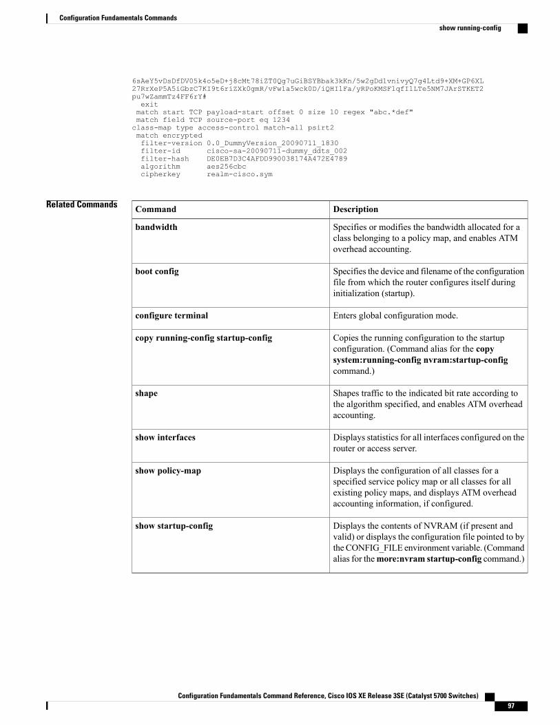
6sAeY5vDsDfDV05k4o5eD+j8cMt78iZT0Qg7uGiBSYBbak3kKn/5w2gDd1vnivyQ7g4Ltd9+XM+GP6XL27RrXeP5A5iGbzC7KI9t6riZXk0gmR/vFw1a5wck0D/iQHIlFa/yRPoKMSFlqfIlLTe5NM7JArSTKET2pu7wZammTz4FF6rY#exitmatch start TCP payload-start offset 0 size 10 regex "abc.*def"match field TCP source-port eq 1234class-map type access-control match-all psirt2match encryptedfilter-version 0.0_DummyVersion_20090711_1830filter-id cisco-sa-20090711-dummy_ddts_002filter-hash DE0EB7D3C4AFDD990038174A472E4789algorithm aes256cbccipherkey realm-cisco.sym
Related Commands DescriptionCommand
Specifies or modifies the bandwidth allocated for aclass belonging to a policy map, and enables ATMoverhead accounting.
bandwidth
Specifies the device and filename of the configurationfile from which the router configures itself duringinitialization (startup).
boot config
Enters global configuration mode.configure terminal
Copies the running configuration to the startupconfiguration. (Command alias for the copysystem:running-config nvram:startup-configcommand.)
copy running-config startup-config
Shapes traffic to the indicated bit rate according tothe algorithm specified, and enables ATM overheadaccounting.
shape
Displays statistics for all interfaces configured on therouter or access server.
show interfaces
Displays the configuration of all classes for aspecified service policy map or all classes for allexisting policy maps, and displays ATM overheadaccounting information, if configured.
show policy-map
Displays the contents of NVRAM (if present andvalid) or displays the configuration file pointed to bythe CONFIG_FILE environment variable. (Commandalias for themore:nvram startup-config command.)
show startup-config
Configuration Fundamentals Command Reference, Cisco IOS XE Release 3SE (Catalyst 5700 Switches) 97
Configuration Fundamentals Commandsshow running-config
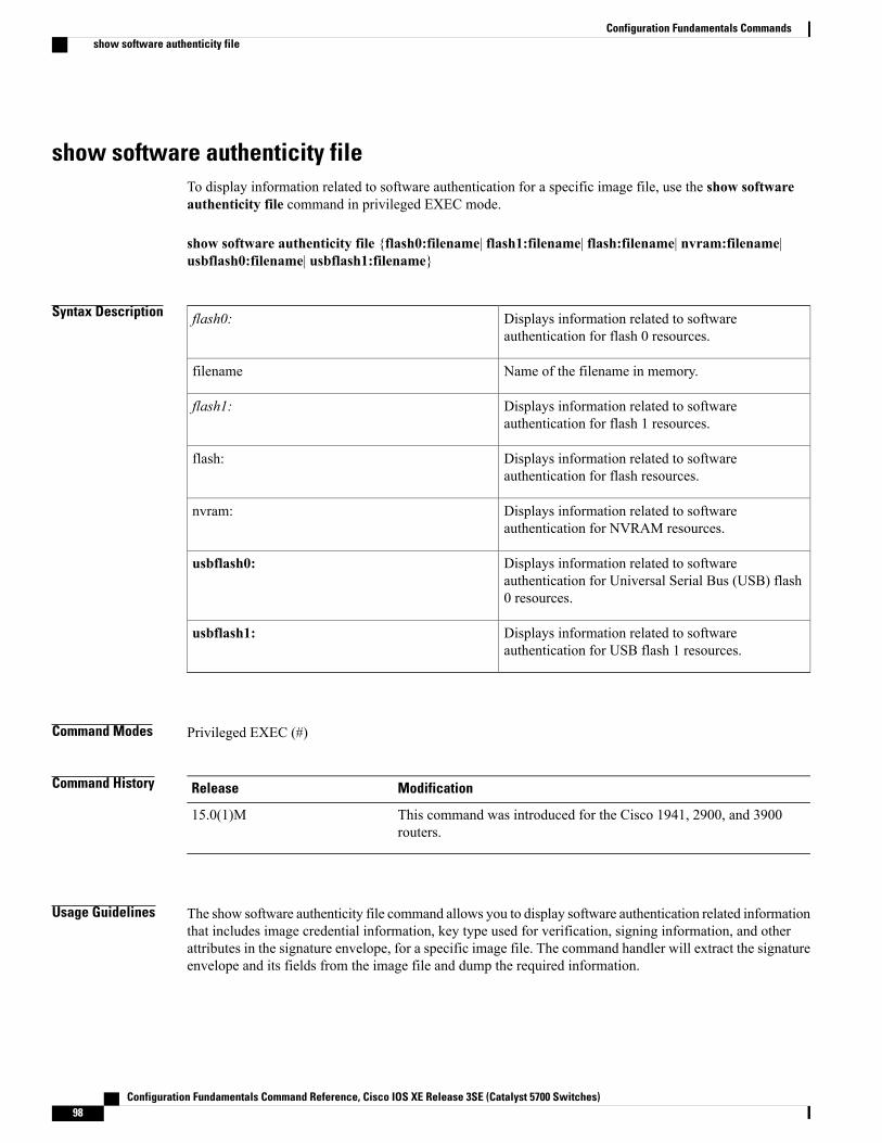
show software authenticity fileTo display information related to software authentication for a specific image file, use the show softwareauthenticity file command in privileged EXEC mode.
show software authenticity file {flash0:filename| flash1:filename| flash:filename| nvram:filename|usbflash0:filename| usbflash1:filename}
Syntax Description Displays information related to softwareauthentication for flash 0 resources.
flash0:
Name of the filename in memory.filename
Displays information related to softwareauthentication for flash 1 resources.
flash1:
Displays information related to softwareauthentication for flash resources.
flash:
Displays information related to softwareauthentication for NVRAM resources.
nvram:
Displays information related to softwareauthentication for Universal Serial Bus (USB) flash0 resources.
usbflash0:
Displays information related to softwareauthentication for USB flash 1 resources.
usbflash1:
Command Modes Privileged EXEC (#)
Command History ModificationRelease
This command was introduced for the Cisco 1941, 2900, and 3900routers.
15.0(1)M
Usage Guidelines The show software authenticity file command allows you to display software authentication related informationthat includes image credential information, key type used for verification, signing information, and otherattributes in the signature envelope, for a specific image file. The command handler will extract the signatureenvelope and its fields from the image file and dump the required information.
Configuration Fundamentals Command Reference, Cisco IOS XE Release 3SE (Catalyst 5700 Switches)98
Configuration Fundamentals Commandsshow software authenticity file
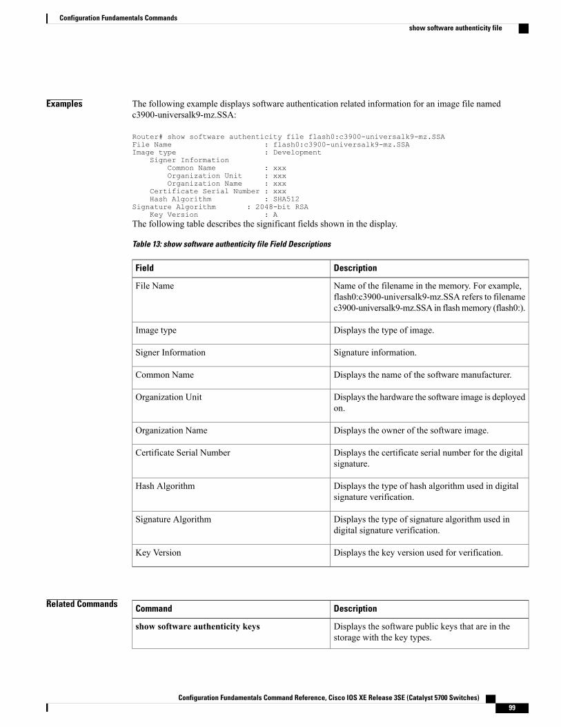
Examples The following example displays software authentication related information for an image file namedc3900-universalk9-mz.SSA:
Router# show software authenticity file flash0:c3900-universalk9-mz.SSAFile Name : flash0:c3900-universalk9-mz.SSAImage type : Development
Signer InformationCommon Name : xxxOrganization Unit : xxxOrganization Name : xxx
Certificate Serial Number : xxxHash Algorithm : SHA512
Signature Algorithm : 2048-bit RSAKey Version : A
The following table describes the significant fields shown in the display.
Table 13: show software authenticity file Field Descriptions
DescriptionField
Name of the filename in the memory. For example,flash0:c3900-universalk9-mz.SSA refers to filenamec3900-universalk9-mz.SSA in flashmemory (flash0:).
File Name
Displays the type of image.Image type
Signature information.Signer Information
Displays the name of the software manufacturer.Common Name
Displays the hardware the software image is deployedon.
Organization Unit
Displays the owner of the software image.Organization Name
Displays the certificate serial number for the digitalsignature.
Certificate Serial Number
Displays the type of hash algorithm used in digitalsignature verification.
Hash Algorithm
Displays the type of signature algorithm used indigital signature verification.
Signature Algorithm
Displays the key version used for verification.Key Version
Related Commands DescriptionCommand
Displays the software public keys that are in thestorage with the key types.
show software authenticity keys
Configuration Fundamentals Command Reference, Cisco IOS XE Release 3SE (Catalyst 5700 Switches) 99
Configuration Fundamentals Commandsshow software authenticity file

DescriptionCommand
Displays information related to softwareauthentication for the current ROMMON, monitorlibrary (monlib), and Cisco IOS image used forbooting.
show software authenticity running
Configuration Fundamentals Command Reference, Cisco IOS XE Release 3SE (Catalyst 5700 Switches)100
Configuration Fundamentals Commandsshow software authenticity file
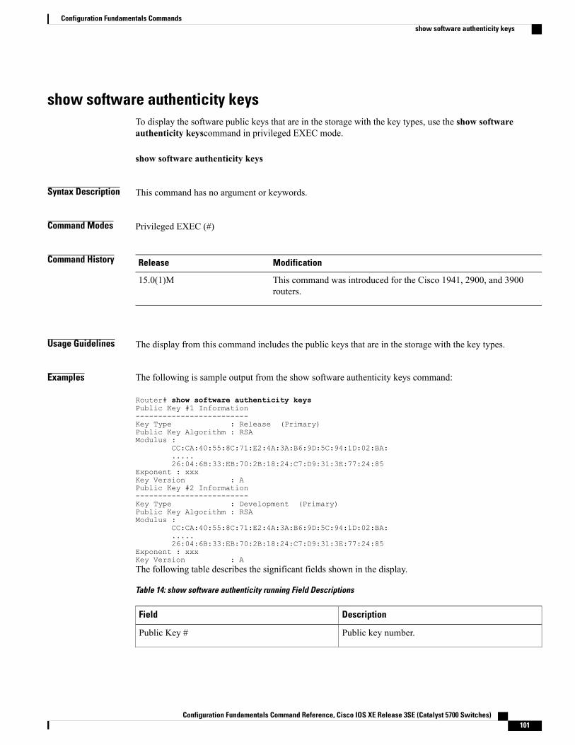
show software authenticity keysTo display the software public keys that are in the storage with the key types, use the show softwareauthenticity keyscommand in privileged EXEC mode.
show software authenticity keys
Syntax Description This command has no argument or keywords.
Command Modes Privileged EXEC (#)
Command History ModificationRelease
This command was introduced for the Cisco 1941, 2900, and 3900routers.
15.0(1)M
Usage Guidelines The display from this command includes the public keys that are in the storage with the key types.
Examples The following is sample output from the show software authenticity keys command:
Router# show software authenticity keysPublic Key #1 Information-------------------------Key Type : Release (Primary)Public Key Algorithm : RSAModulus :
CC:CA:40:55:8C:71:E2:4A:3A:B6:9D:5C:94:1D:02:BA:.....26:04:6B:33:EB:70:2B:18:24:C7:D9:31:3E:77:24:85
Exponent : xxxKey Version : APublic Key #2 Information-------------------------Key Type : Development (Primary)Public Key Algorithm : RSAModulus :
CC:CA:40:55:8C:71:E2:4A:3A:B6:9D:5C:94:1D:02:BA:.....26:04:6B:33:EB:70:2B:18:24:C7:D9:31:3E:77:24:85
Exponent : xxxKey Version : AThe following table describes the significant fields shown in the display.
Table 14: show software authenticity running Field Descriptions
DescriptionField
Public key number.Public Key #
Configuration Fundamentals Command Reference, Cisco IOS XE Release 3SE (Catalyst 5700 Switches) 101
Configuration Fundamentals Commandsshow software authenticity keys
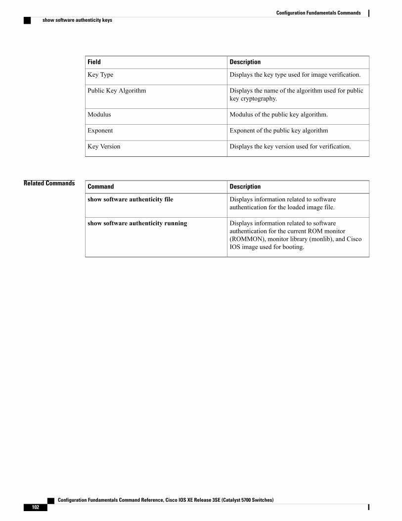
DescriptionField
Displays the key type used for image verification.Key Type
Displays the name of the algorithm used for publickey cryptography.
Public Key Algorithm
Modulus of the public key algorithm.Modulus
Exponent of the public key algorithmExponent
Displays the key version used for verification.Key Version
Related Commands DescriptionCommand
Displays information related to softwareauthentication for the loaded image file.
show software authenticity file
Displays information related to softwareauthentication for the current ROM monitor(ROMMON), monitor library (monlib), and CiscoIOS image used for booting.
show software authenticity running
Configuration Fundamentals Command Reference, Cisco IOS XE Release 3SE (Catalyst 5700 Switches)102
Configuration Fundamentals Commandsshow software authenticity keys
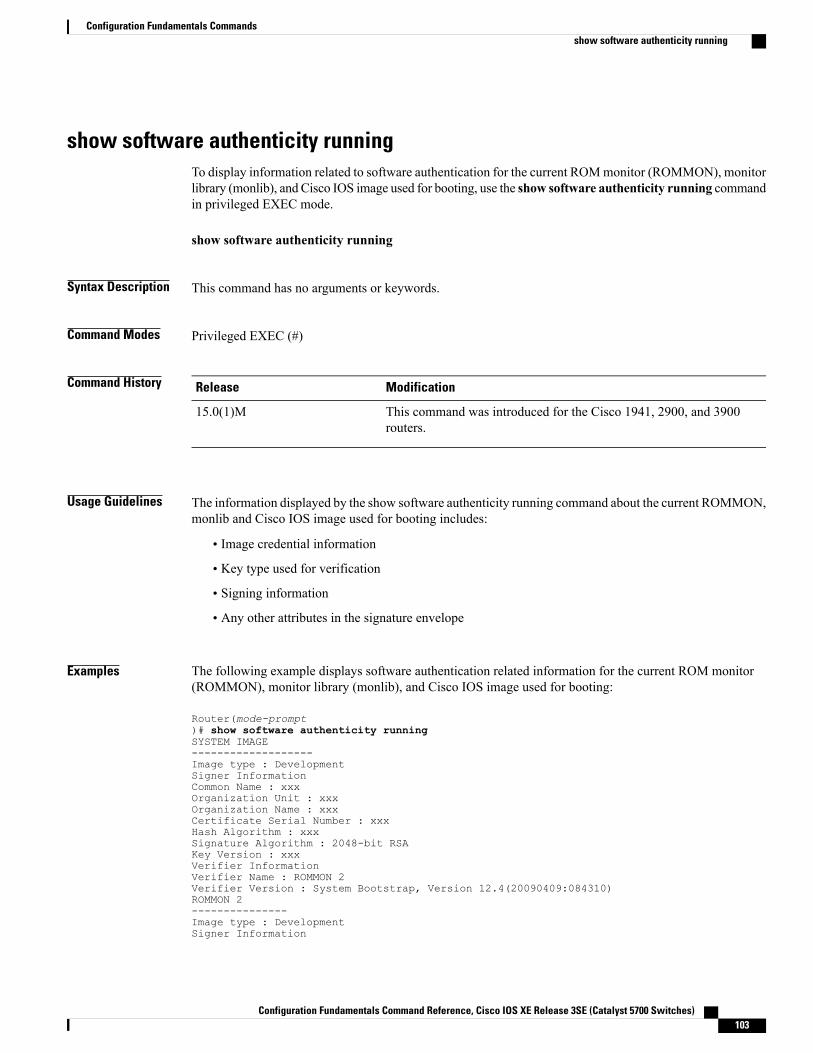
show software authenticity runningTo display information related to software authentication for the current ROMmonitor (ROMMON), monitorlibrary (monlib), and Cisco IOS image used for booting, use the show software authenticity running commandin privileged EXEC mode.
show software authenticity running
Syntax Description This command has no arguments or keywords.
Command Modes Privileged EXEC (#)
Command History ModificationRelease
This command was introduced for the Cisco 1941, 2900, and 3900routers.
15.0(1)M
Usage Guidelines The information displayed by the show software authenticity running command about the current ROMMON,monlib and Cisco IOS image used for booting includes:
• Image credential information
• Key type used for verification
• Signing information
• Any other attributes in the signature envelope
Examples The following example displays software authentication related information for the current ROM monitor(ROMMON), monitor library (monlib), and Cisco IOS image used for booting:
Router(mode-prompt)# show software authenticity runningSYSTEM IMAGE-------------------Image type : DevelopmentSigner InformationCommon Name : xxxOrganization Unit : xxxOrganization Name : xxxCertificate Serial Number : xxxHash Algorithm : xxxSignature Algorithm : 2048-bit RSAKey Version : xxxVerifier InformationVerifier Name : ROMMON 2Verifier Version : System Bootstrap, Version 12.4(20090409:084310)ROMMON 2---------------Image type : DevelopmentSigner Information
Configuration Fundamentals Command Reference, Cisco IOS XE Release 3SE (Catalyst 5700 Switches) 103
Configuration Fundamentals Commandsshow software authenticity running
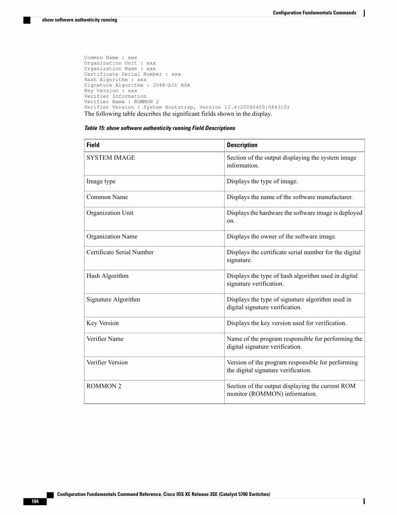
Common Name : xxxOrganization Unit : xxxOrganization Name : xxxCertificate Serial Number : xxxHash Algorithm : xxxSignature Algorithm : 2048-bit RSAKey Version : xxxVerifier InformationVerifier Name : ROMMON 2Verifier Version : System Bootstrap, Version 12.4(20090409:084310)The following table describes the significant fields shown in the display.
Table 15: show software authenticity running Field Descriptions
DescriptionField
Section of the output displaying the system imageinformation.
SYSTEM IMAGE
Displays the type of image.Image type
Displays the name of the software manufacturer.Common Name
Displays the hardware the software image is deployedon.
Organization Unit
Displays the owner of the software image.Organization Name
Displays the certificate serial number for the digitalsignature.
Certificate Serial Number
Displays the type of hash algorithm used in digitalsignature verification.
Hash Algorithm
Displays the type of signature algorithm used indigital signature verification.
Signature Algorithm
Displays the key version used for verification.Key Version
Name of the program responsible for performing thedigital signature verification.
Verifier Name
Version of the program responsible for performingthe digital signature verification.
Verifier Version
Section of the output displaying the current ROMmonitor (ROMMON) information.
ROMMON 2
Configuration Fundamentals Command Reference, Cisco IOS XE Release 3SE (Catalyst 5700 Switches)104
Configuration Fundamentals Commandsshow software authenticity running
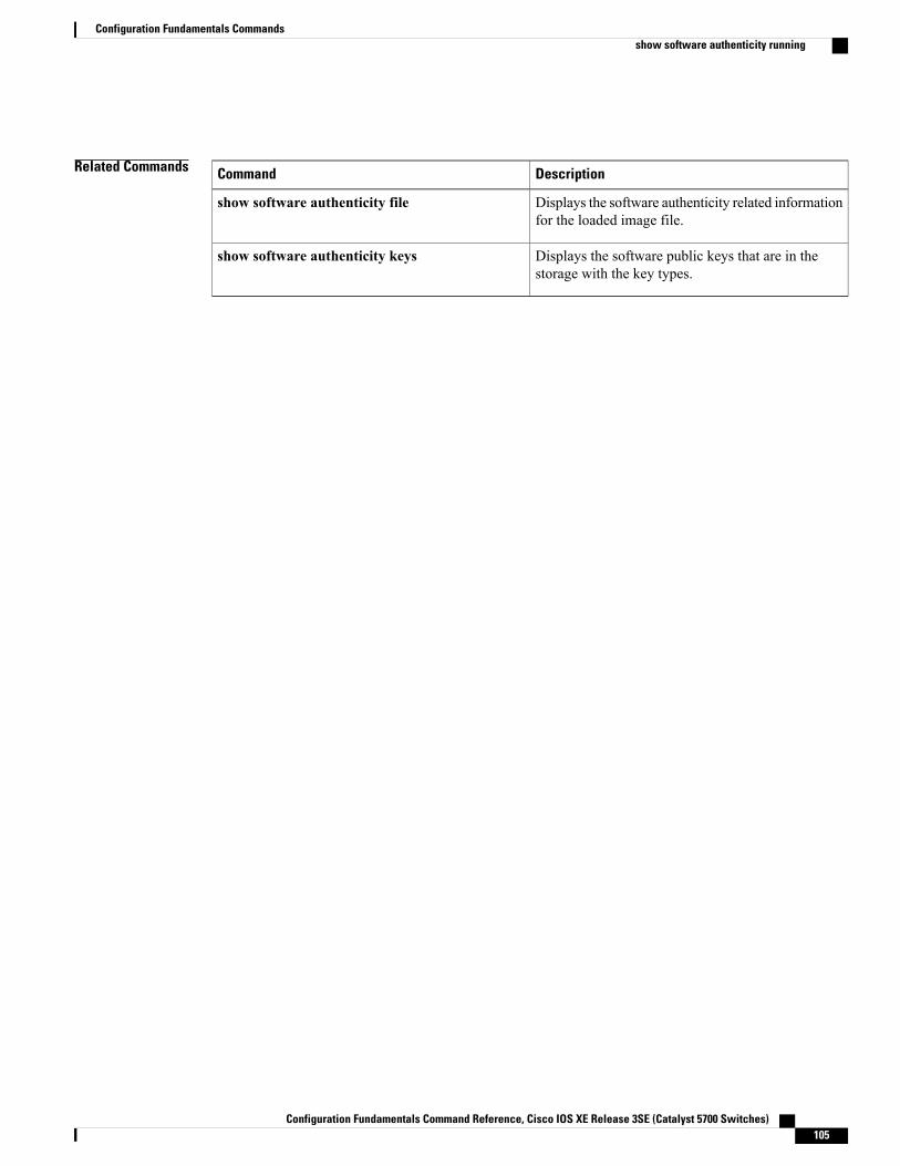
Related Commands DescriptionCommand
Displays the software authenticity related informationfor the loaded image file.
show software authenticity file
Displays the software public keys that are in thestorage with the key types.
show software authenticity keys
Configuration Fundamentals Command Reference, Cisco IOS XE Release 3SE (Catalyst 5700 Switches) 105
Configuration Fundamentals Commandsshow software authenticity running

show software installer rollback-timerThe show software installer rollback-timer command displays the current auto-rollback timer status for astandalone platform or all switches in a stacked system.
show software installer rollback-timer
Command Default There are no command options.
Command Modes User EXEC (>) Privileged EXEC (#)
Command History ModificationRelease
Command introduced.IOS XE 3.2.0 SE
This command was integrated.Cisco IOS XE Release 3.3 SE
Usage Guidelines There are no command options.
Examples To show the auto-rollback timer status for the current switch, perform the following.infra-p2-3#show software installer rollback-timerSwitch# Status Duration----------------------------------1 active 00:31:282 active 00:31:43
infra-p2-3#
infra-p2-3#show software installer rollback-timerSwitch# Status Duration----------------------------------1 inactive -2 inactive -
infra-p2-3#
Related Commands DescriptionCommand
Use this command to remove anyand all packages and provisioningfiles that are no longer in use.
software clean
Install Cisco IOS XE files.software install file
Configuration Fundamentals Command Reference, Cisco IOS XE Release 3SE (Catalyst 5700 Switches)106
Configuration Fundamentals Commandsshow software installer rollback-timer
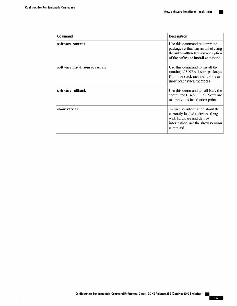
DescriptionCommand
Use this command to commit apackage set that was installed usingthe auto-rollback command optionof the software install command.
software commit
Use this command to install therunning IOSXE software packagesfrom one stack member to one ormore other stack members.
software install source switch
Use this command to roll back thecommitted Cisco IOSXE Softwareto a previous installation point.
software rollback
To display information about thecurrently loaded software alongwith hardware and deviceinformation, use the show versioncommand.
show version
Configuration Fundamentals Command Reference, Cisco IOS XE Release 3SE (Catalyst 5700 Switches) 107
Configuration Fundamentals Commandsshow software installer rollback-timer
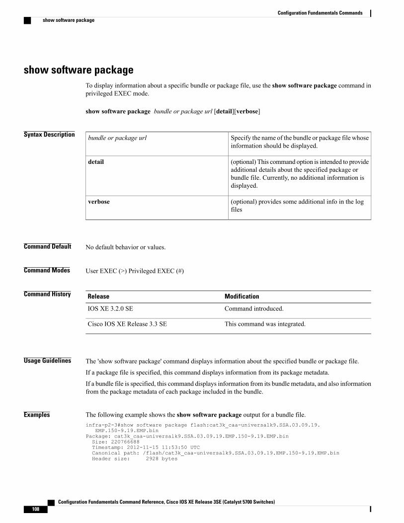
show software packageTo display information about a specific bundle or package file, use the show software package command inprivileged EXEC mode.
show software package bundle or package url [detail][verbose]
Syntax Description Specify the name of the bundle or package file whoseinformation should be displayed.
bundle or package url
(optional) This command option is intended to provideadditional details about the specified package orbundle file. Currently, no additional information isdisplayed.
detail
(optional) provides some additional info in the logfiles
verbose
Command Default No default behavior or values.
Command Modes User EXEC (>) Privileged EXEC (#)
Command History ModificationRelease
Command introduced.IOS XE 3.2.0 SE
This command was integrated.Cisco IOS XE Release 3.3 SE
Usage Guidelines The 'show software package' command displays information about the specified bundle or package file.
If a package file is specified, this command displays information from its package metadata.
If a bundle file is specified, this command displays information from its bundle metadata, and also informationfrom the package metadata of each package included in the bundle.
Examples The following example shows the show software package output for a bundle file.infra-p2-3#show software package flash:cat3k_caa-universalk9.SSA.03.09.19.
EMP.150-9.19.EMP.binPackage: cat3k_caa-universalk9.SSA.03.09.19.EMP.150-9.19.EMP.binSize: 220766688Timestamp: 2012-11-15 11:53:50 UTCCanonical path: /flash/cat3k_caa-universalk9.SSA.03.09.19.EMP.150-9.19.EMP.binHeader size: 2928 bytes
Configuration Fundamentals Command Reference, Cisco IOS XE Release 3SE (Catalyst 5700 Switches)108
Configuration Fundamentals Commandsshow software package
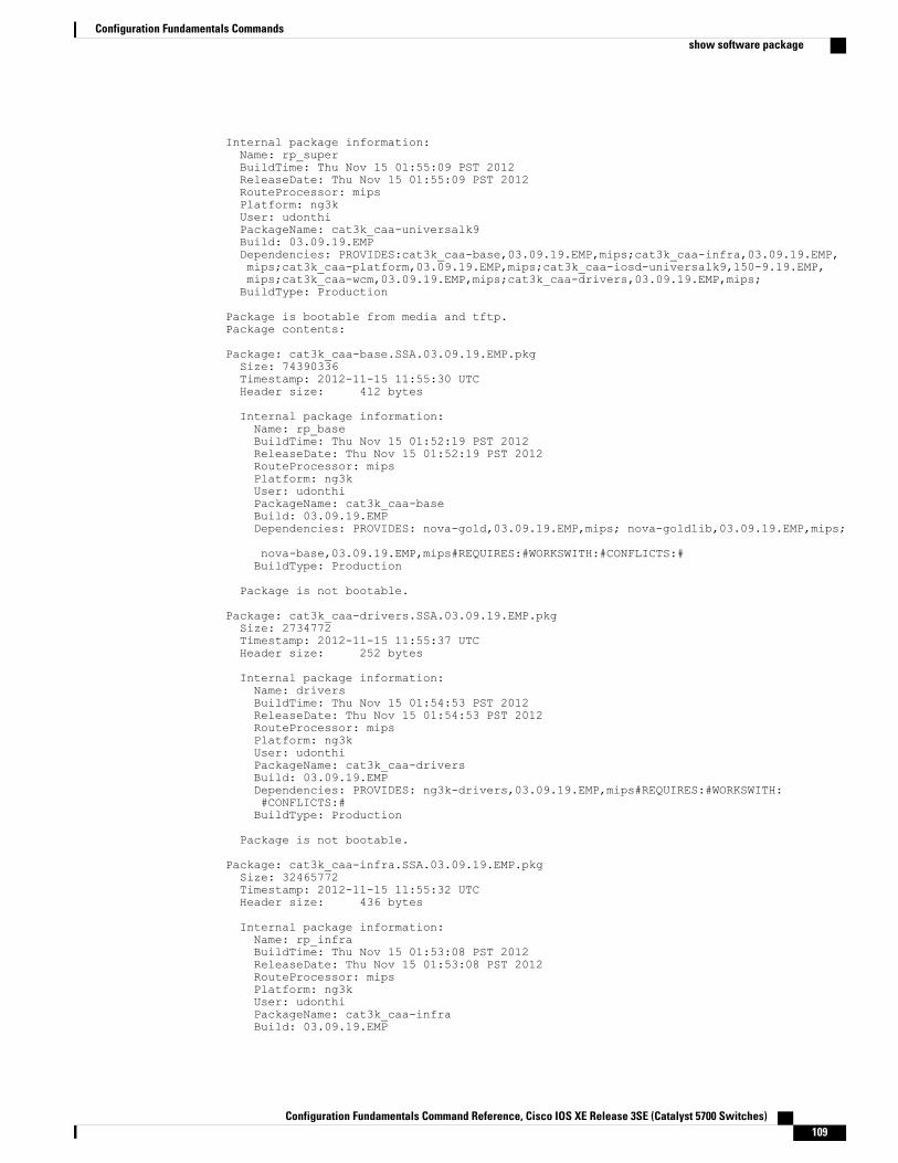
Internal package information:Name: rp_superBuildTime: Thu Nov 15 01:55:09 PST 2012ReleaseDate: Thu Nov 15 01:55:09 PST 2012RouteProcessor: mipsPlatform: ng3kUser: udonthiPackageName: cat3k_caa-universalk9Build: 03.09.19.EMPDependencies: PROVIDES:cat3k_caa-base,03.09.19.EMP,mips;cat3k_caa-infra,03.09.19.EMP,mips;cat3k_caa-platform,03.09.19.EMP,mips;cat3k_caa-iosd-universalk9,150-9.19.EMP,mips;cat3k_caa-wcm,03.09.19.EMP,mips;cat3k_caa-drivers,03.09.19.EMP,mips;BuildType: Production
Package is bootable from media and tftp.Package contents:
Package: cat3k_caa-base.SSA.03.09.19.EMP.pkgSize: 74390336Timestamp: 2012-11-15 11:55:30 UTCHeader size: 412 bytes
Internal package information:Name: rp_baseBuildTime: Thu Nov 15 01:52:19 PST 2012ReleaseDate: Thu Nov 15 01:52:19 PST 2012RouteProcessor: mipsPlatform: ng3kUser: udonthiPackageName: cat3k_caa-baseBuild: 03.09.19.EMPDependencies: PROVIDES: nova-gold,03.09.19.EMP,mips; nova-goldlib,03.09.19.EMP,mips;
nova-base,03.09.19.EMP,mips#REQUIRES:#WORKSWITH:#CONFLICTS:#BuildType: Production
Package is not bootable.
Package: cat3k_caa-drivers.SSA.03.09.19.EMP.pkgSize: 2734772Timestamp: 2012-11-15 11:55:37 UTCHeader size: 252 bytes
Internal package information:Name: driversBuildTime: Thu Nov 15 01:54:53 PST 2012ReleaseDate: Thu Nov 15 01:54:53 PST 2012RouteProcessor: mipsPlatform: ng3kUser: udonthiPackageName: cat3k_caa-driversBuild: 03.09.19.EMPDependencies: PROVIDES: ng3k-drivers,03.09.19.EMP,mips#REQUIRES:#WORKSWITH:#CONFLICTS:#BuildType: Production
Package is not bootable.
Package: cat3k_caa-infra.SSA.03.09.19.EMP.pkgSize: 32465772Timestamp: 2012-11-15 11:55:32 UTCHeader size: 436 bytes
Internal package information:Name: rp_infraBuildTime: Thu Nov 15 01:53:08 PST 2012ReleaseDate: Thu Nov 15 01:53:08 PST 2012RouteProcessor: mipsPlatform: ng3kUser: udonthiPackageName: cat3k_caa-infraBuild: 03.09.19.EMP
Configuration Fundamentals Command Reference, Cisco IOS XE Release 3SE (Catalyst 5700 Switches) 109
Configuration Fundamentals Commandsshow software package
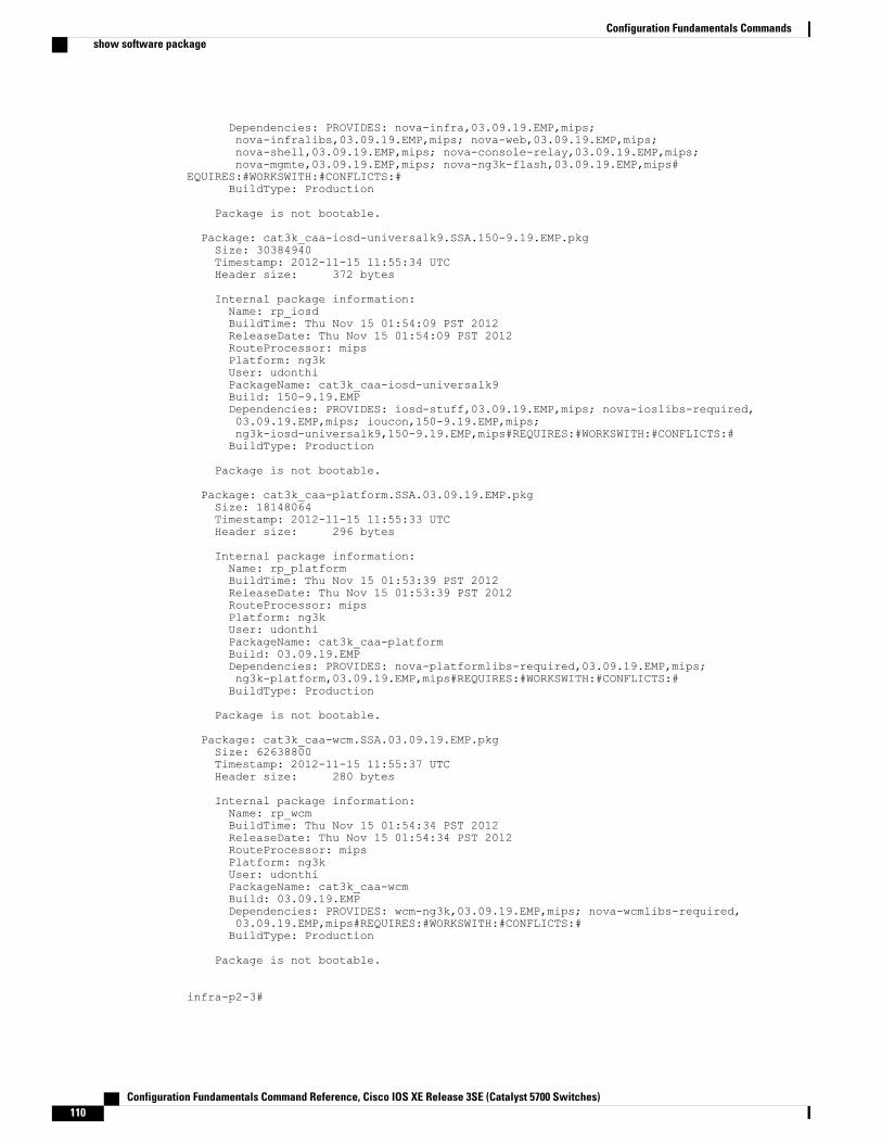
Dependencies: PROVIDES: nova-infra,03.09.19.EMP,mips;nova-infralibs,03.09.19.EMP,mips; nova-web,03.09.19.EMP,mips;nova-shell,03.09.19.EMP,mips; nova-console-relay,03.09.19.EMP,mips;nova-mgmte,03.09.19.EMP,mips; nova-ng3k-flash,03.09.19.EMP,mips#
EQUIRES:#WORKSWITH:#CONFLICTS:#BuildType: Production
Package is not bootable.
Package: cat3k_caa-iosd-universalk9.SSA.150-9.19.EMP.pkgSize: 30384940Timestamp: 2012-11-15 11:55:34 UTCHeader size: 372 bytes
Internal package information:Name: rp_iosdBuildTime: Thu Nov 15 01:54:09 PST 2012ReleaseDate: Thu Nov 15 01:54:09 PST 2012RouteProcessor: mipsPlatform: ng3kUser: udonthiPackageName: cat3k_caa-iosd-universalk9Build: 150-9.19.EMPDependencies: PROVIDES: iosd-stuff,03.09.19.EMP,mips; nova-ioslibs-required,03.09.19.EMP,mips; ioucon,150-9.19.EMP,mips;ng3k-iosd-universalk9,150-9.19.EMP,mips#REQUIRES:#WORKSWITH:#CONFLICTS:#BuildType: Production
Package is not bootable.
Package: cat3k_caa-platform.SSA.03.09.19.EMP.pkgSize: 18148064Timestamp: 2012-11-15 11:55:33 UTCHeader size: 296 bytes
Internal package information:Name: rp_platformBuildTime: Thu Nov 15 01:53:39 PST 2012ReleaseDate: Thu Nov 15 01:53:39 PST 2012RouteProcessor: mipsPlatform: ng3kUser: udonthiPackageName: cat3k_caa-platformBuild: 03.09.19.EMPDependencies: PROVIDES: nova-platformlibs-required,03.09.19.EMP,mips;ng3k-platform,03.09.19.EMP,mips#REQUIRES:#WORKSWITH:#CONFLICTS:#BuildType: Production
Package is not bootable.
Package: cat3k_caa-wcm.SSA.03.09.19.EMP.pkgSize: 62638800Timestamp: 2012-11-15 11:55:37 UTCHeader size: 280 bytes
Internal package information:Name: rp_wcmBuildTime: Thu Nov 15 01:54:34 PST 2012ReleaseDate: Thu Nov 15 01:54:34 PST 2012RouteProcessor: mipsPlatform: ng3kUser: udonthiPackageName: cat3k_caa-wcmBuild: 03.09.19.EMPDependencies: PROVIDES: wcm-ng3k,03.09.19.EMP,mips; nova-wcmlibs-required,03.09.19.EMP,mips#REQUIRES:#WORKSWITH:#CONFLICTS:#BuildType: Production
Package is not bootable.
infra-p2-3#
Configuration Fundamentals Command Reference, Cisco IOS XE Release 3SE (Catalyst 5700 Switches)110
Configuration Fundamentals Commandsshow software package
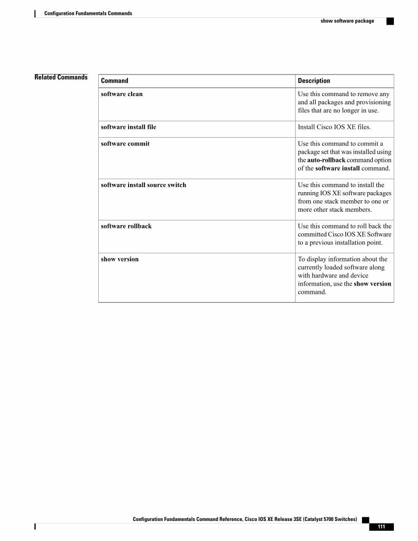
Related Commands DescriptionCommand
Use this command to remove anyand all packages and provisioningfiles that are no longer in use.
software clean
Install Cisco IOS XE files.software install file
Use this command to commit apackage set that was installed usingthe auto-rollback command optionof the software install command.
software commit
Use this command to install therunning IOSXE software packagesfrom one stack member to one ormore other stack members.
software install source switch
Use this command to roll back thecommitted Cisco IOSXE Softwareto a previous installation point.
software rollback
To display information about thecurrently loaded software alongwith hardware and deviceinformation, use the show versioncommand.
show version
Configuration Fundamentals Command Reference, Cisco IOS XE Release 3SE (Catalyst 5700 Switches) 111
Configuration Fundamentals Commandsshow software package
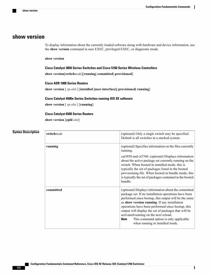
show versionTo display information about the currently loaded software along with hardware and device information, usethe show version command in user EXEC, privileged EXEC, or diagnostic mode.
show version
Cisco Catalyst 3850 Series Switches and Cisco 5760 Series Wireless Controllers
show version[switchnode][running| committed| provisioned]
Cisco ASR 1000 Series Routers
show version [ rp-slot ] [installed [user-interface]| provisioned| running]
Cisco Catalyst 4500e Series Switches running IOS XE software
show version [ rp-slot ] [running]
Cisco Catalyst 6500 Series Routers
show version [epld slot]
Syntax Description (optional) Only a single switch may be specified.Default is all switches in a stacked system.
switchnode
(optional) Specifies information on the files currentlyrunning.
cat3850 and ct5760: (optional) Displays informationabout the active package set currently running on theswitch. When booted in installed mode, this istypically the set of packages listed in the bootedprovisioning file. When booted in bundle mode, thisis typically the set of packages contained in the bootedbundle.
running
(optional) Displays information about the committedpackage set. If no installation operations have beenperformed since bootup, this output will be the sameas show version running. If any installationoperations have been performed since bootup, thisoutput will display the set of packages that will beactivated/running on the next reload.
This command option is only applicablewhen running in installed mode.
Note
committed
Configuration Fundamentals Command Reference, Cisco IOS XE Release 3SE (Catalyst 5700 Switches)112
Configuration Fundamentals Commandsshow version
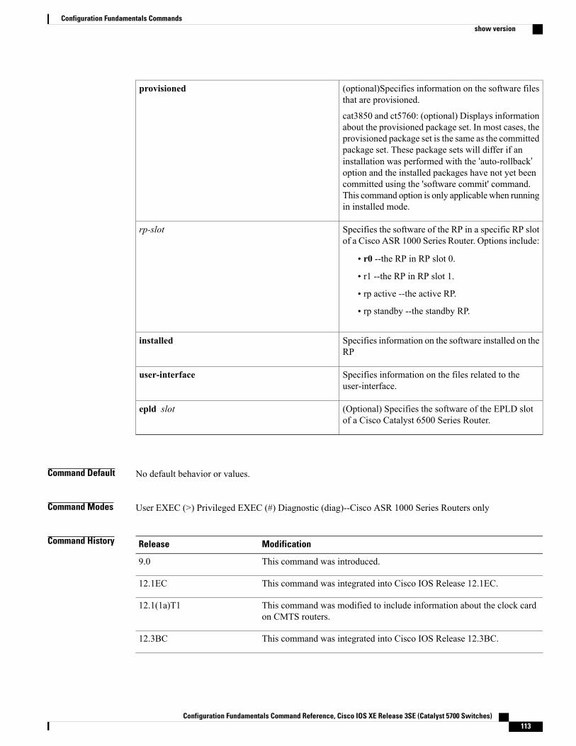
(optional)Specifies information on the software filesthat are provisioned.
cat3850 and ct5760: (optional) Displays informationabout the provisioned package set. In most cases, theprovisioned package set is the same as the committedpackage set. These package sets will differ if aninstallation was performed with the ‘auto-rollback’option and the installed packages have not yet beencommitted using the 'software commit' command.This command option is only applicablewhen runningin installed mode.
provisioned
Specifies the software of the RP in a specific RP slotof a Cisco ASR 1000 Series Router. Options include:
• r0 --the RP in RP slot 0.
• r1 --the RP in RP slot 1.
• rp active --the active RP.
• rp standby --the standby RP.
rp-slot
Specifies information on the software installed on theRP
installed
Specifies information on the files related to theuser-interface.
user-interface
(Optional) Specifies the software of the EPLD slotof a Cisco Catalyst 6500 Series Router.
epld slot
Command Default No default behavior or values.
Command Modes User EXEC (>) Privileged EXEC (#) Diagnostic (diag)--Cisco ASR 1000 Series Routers only
Command History ModificationRelease
This command was introduced.9.0
This command was integrated into Cisco IOS Release 12.1EC.12.1EC
This command was modified to include information about the clock cardon CMTS routers.
12.1(1a)T1
This command was integrated into Cisco IOS Release 12.3BC.12.3BC
Configuration Fundamentals Command Reference, Cisco IOS XE Release 3SE (Catalyst 5700 Switches) 113
Configuration Fundamentals Commandsshow version
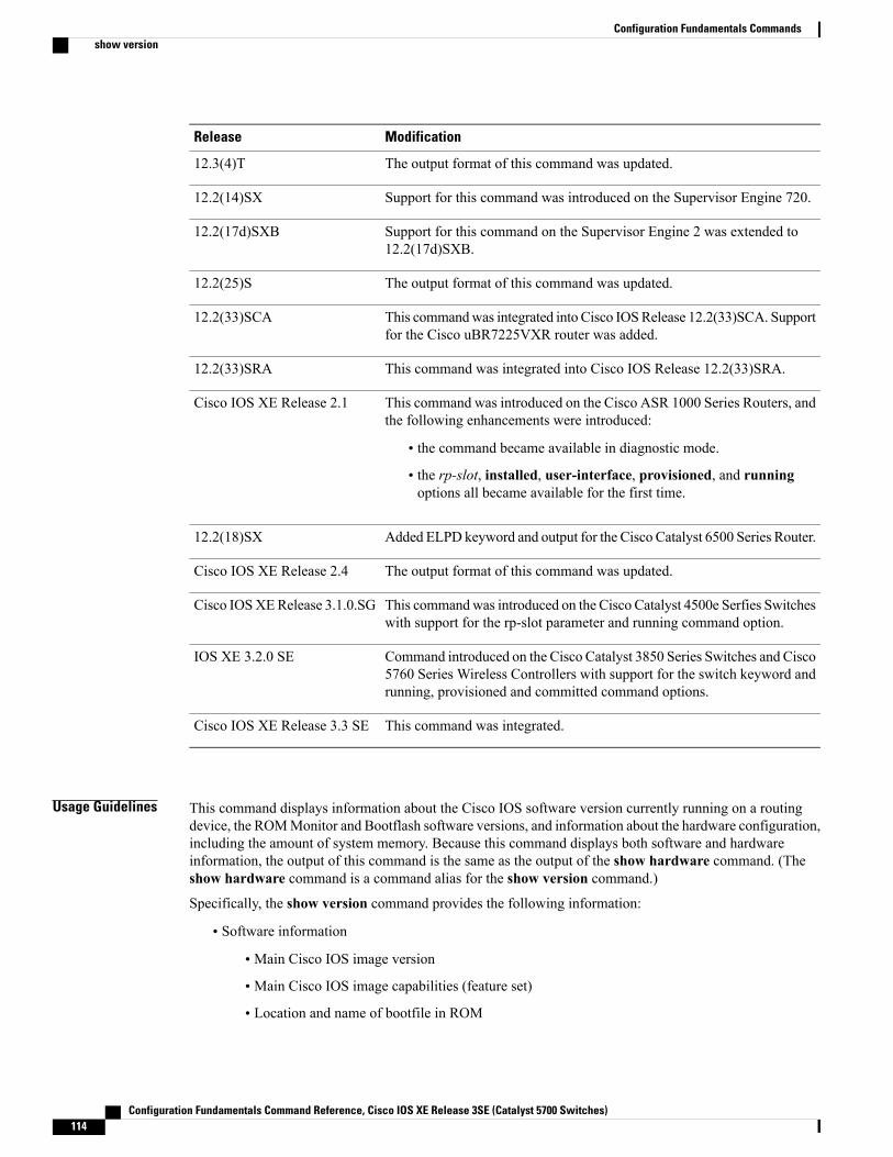
ModificationRelease
The output format of this command was updated.12.3(4)T
Support for this command was introduced on the Supervisor Engine 720.12.2(14)SX
Support for this command on the Supervisor Engine 2 was extended to12.2(17d)SXB.
12.2(17d)SXB
The output format of this command was updated.12.2(25)S
This commandwas integrated into Cisco IOSRelease 12.2(33)SCA. Supportfor the Cisco uBR7225VXR router was added.
12.2(33)SCA
This command was integrated into Cisco IOS Release 12.2(33)SRA.12.2(33)SRA
This command was introduced on the Cisco ASR 1000 Series Routers, andthe following enhancements were introduced:
• the command became available in diagnostic mode.
• the rp-slot, installed, user-interface, provisioned, and runningoptions all became available for the first time.
Cisco IOS XE Release 2.1
Added ELPD keyword and output for the Cisco Catalyst 6500 Series Router.12.2(18)SX
The output format of this command was updated.Cisco IOS XE Release 2.4
This commandwas introduced on the Cisco Catalyst 4500e Serfies Switcheswith support for the rp-slot parameter and running command option.
Cisco IOSXERelease 3.1.0.SG
Command introduced on the Cisco Catalyst 3850 Series Switches and Cisco5760 Series Wireless Controllers with support for the switch keyword andrunning, provisioned and committed command options.
IOS XE 3.2.0 SE
This command was integrated.Cisco IOS XE Release 3.3 SE
Usage Guidelines This command displays information about the Cisco IOS software version currently running on a routingdevice, the ROMMonitor and Bootflash software versions, and information about the hardware configuration,including the amount of system memory. Because this command displays both software and hardwareinformation, the output of this command is the same as the output of the show hardware command. (Theshow hardware command is a command alias for the show version command.)
Specifically, the show version command provides the following information:
• Software information
• Main Cisco IOS image version
• Main Cisco IOS image capabilities (feature set)
• Location and name of bootfile in ROM
Configuration Fundamentals Command Reference, Cisco IOS XE Release 3SE (Catalyst 5700 Switches)114
Configuration Fundamentals Commandsshow version
• Bootflash image version (depending on platform)
• Device-specific information
• Device name
• System uptime
• System reload reason
• Config-register setting
• Config-register settings for after the next reload (depending on platform)
• Hardware information
• Platform type
• Processor type
• Processor hardware revision
• Amount of main (processor) memory installed
• Amount I/O memory installed
• Amount of Flash memory installed on different types (depending on platform)
• Processor board ID
The output of this command uses the following format:
Cisco IOS Software, <platform> Software (<image-id>), Version <software-version>,<software-type
Technical Support: http://www.cisco.com/techsupportCopyright (c) <date-range> by Cisco Systems, Inc.Compiled <day> <date> <time> by <compiler-id>
ROM: System Bootstrap, Version <software-version>, <software-type>BOOTLDR: <platform> Software (image-id), Version <software-version>, <software-type>
<router-name> uptime is <w> weeks, <d> days, <h> hours,<m> minutesSystem returned to ROM by reload at <time> <day> <date>System image file is "<filesystem-location>/<software-image-name>"Last reload reason: <reload-reason>Cisco <platform-processor-type>processor (revision <processor-revision-id>) with <free-DRAM-memory>K/<packet-memory>K bytes of memory.Processor board ID <ID-number
<CPU-type> CPU at <clock-speed>Mhz, Implementation <number>, Rev <Revision-number>, <kilobytes-Processor-Cache-Memory>KB <cache-Level> CacheSee the Examples section for descriptions of the fields in this output.
Cisco ASR 1000 Series Routers
Entering show versionwithout any of the options on the Cisco ASR 1000 Series Router will generate outputsimilar to show version on other Cisco routers.
In order to understand the show versionoutput on Cisco ASR 1000 Series Routers, it is important to understandthat the individual sub-packages run the processes on the router. Among other things, the output of thiscommand provides information on where various individual sub-packages are stored on the router, and whichprocesses these individual sub-packages are and are not currently running.
Configuration Fundamentals Command Reference, Cisco IOS XE Release 3SE (Catalyst 5700 Switches) 115
Configuration Fundamentals Commandsshow version
More specifically, the command displays each individual sub-package file on the router, the hardware wherethe sub-package could be running, and whether the sub-package is currently being run on that hardware.
The show version provisioned command displays only the individual sub-packages that can be provisioned,which are the RP-specific sub-packages (RP Access, RP Base, RP Control, and RP IOS) and the provisioningfile. The output includes the individual sub-package file, the hardware where the sub-package could be running,and whether the sub-package is currently being run on that hardware.
The command displays only the individual sub-packages that are currently active. The output includes theindividual sub-package file and the hardware where the sub-package is running.
Cisco Catalyst 4500e Series Switches
Entering show version without any of the options on a Cisco Catalyst 4500e Series Switch running IOS XEsoftware will generate output similar to show version on other Cisco platforms. One notable difference isthat the output displays the IOS XE software version instead of the IOS image version.
The IOS XE software bundle includes a set of individual packages that comprise the complete set of softwarethat runs on the switch. The show version running command displays the list individual packages that arecurrently active, that is, the set of packages included in the IOS XE software bundle currently running on theCisco Catalyst 4500e Series Switch.
Cisco Catalyst 3850 Series Switches and Cisco 5760 Series Wireless Controllers
Entering show version without any of the options on a Cisco Catalyst 3850 Series Switch or Cisco 5760SeriesWireless Controller will generate output similar to show version on other Cisco platforms. One notabledifference is that the output displays the IOS XE software version instead of the IOS image version.
The IOS XE software bundle includes a set of individual packages that comprise the complete set of softwarethat runs on the switch or wireless controller.
The show version running command displays the list of individual packages that are currently running onthe switch.When booted in installed mode, this is typically the set of packages listed in the booted provisioningfile. When booted in bundle mode, this is typically the set of packages contained in the bundle.
The show version committed command displays information about the switch's or wireless controller'scommitted package set. If no installation operations have been performed since bootup, this output will bethe same as show version running. If any installation operations have been performed since bootup, thisoutput will display the set of packages that will be activated/running on the next reload. This command is notapplicable when running in bundle mode.
The show version provisioned command displays information about the provisioned package set. In mostcases, the provisioned package set is the same as the committed package set. These package sets will differif an installation was performed with the auto-rollback option and the installed packages have not yet beencommitted by use of the software commit command. This command is not applicable when running in bundlemode.
Examples
Examples The following is sample output from the show version command issued on a Cisco 3660 running Cisco IOSRelease 12.3(4)T:
Router# show version
Cisco IOS Software, 3600 Software (C3660-I-M), Version 12.3(4)TTAC Support: http://www.cisco.com/tacCopyright (c) 1986-2003 by Cisco Systems, Inc.Compiled Thu 18-Sep-03 15:37 by ccaiROM: System Bootstrap, Version 12.0(6r)T, RELEASE SOFTWARE (fc1)
Configuration Fundamentals Command Reference, Cisco IOS XE Release 3SE (Catalyst 5700 Switches)116
Configuration Fundamentals Commandsshow version
ROM:C3660-1 uptime is 1 week, 3 days, 6 hours, 41 minutesSystem returned to ROM by power-onSystem image file is "slot0:tftpboot/c3660-i-mz.123-4.T"Cisco 3660 (R527x) processor (revision 1.0) with 57344K/8192K bytes of memory.Processor board ID JAB055180FFR527x CPU at 225Mhz, Implementation 40, Rev 10.0, 2048KB L2 Cache3660 Chassis type: ENTERPRISE2 FastEthernet interfaces4 Serial interfacesDRAM configuration is 64 bits wide with parity disabled.125K bytes of NVRAM.16384K bytes of processor board System flash (Read/Write)Flash card inserted. Reading filesystem...done.20480K bytes of processor board PCMCIA Slot0 flash (Read/Write)Configuration register is 0x2102
Examples The following is sample output from the show version command issued on a Cisco 7200 router running CiscoIOS Release 12.4(4)T. This output shows the total bandwidth capacity and the bandwith capacity that isconfigured on the Cisco 7200. Displaying bandwidth capacity is available in Cisco IOS Release 12.2 and laterreleases.
Router# show versionCisco IOS Software, 7200 Software (C7200-JS-M), Version 12.4(4)T, RELEASE SOFTW)Technical Support: http://www.cisco.com/techsupportCopyright (c) 1986-2005 by Cisco Systems, Inc.Compiled Thu 27-Oct-05 05:58 by ccaiROM: System Bootstrap, Version 12.1(20000710:044039) [nlaw-121E_npeb 117], DEVEEBOOTLDR: 7200 Software (C7200-KBOOT-M), Version 12.3(16), RELEASE SOFTWARE (fc4)router uptime is 5 days, 18 hours, 2 minutesSystem returned to ROM by reload at 02:45:12 UTC Tue Feb 14 2006System image file is "disk0:c7200-js-mz.124-4.T"Last reload reason: Reload CommandCisco 7206VXR (NPE400) processor (revision A) with 491520K/32768K bytes of memo.Processor board ID 26793934R7000 CPU at 350MHz, Implementation 39, Rev 3.2, 256KB L2 Cache6 slot VXR midplane, Version 2.6Last reset from power-on
PCI bus mb0_mb1 (Slots 0, 1, 3 and 5) has a capacity of 600 bandwidth points.Current configuration on bus mb0_mb1 has a total of 440 bandwidth points.This configuration is within the PCI bus capacity and is supported.PCI bus mb2 (Slots 2, 4, 6) has a capacity of 600 bandwidth points.Current configuration on bus mb2 has a total of 390 bandwidth pointsThis configuration is within the PCI bus capacity and is supported.Please refer to the following document "Cisco 7200 Series Port AdaptorHardware Configuration Guidelines" on Cisco.com <http://www.cisco.com>for c7200 bandwidth points oversubscription and usage guidelines.4 Ethernet interfaces2 FastEthernet interfaces2 ATM interfaces125K bytes of NVRAM.62976K bytes of ATA PCMCIA card at slot 0 (Sector size 512 bytes).125952K bytes of ATA PCMCIA card at slot 1 (Sector size 512 bytes).8192K bytes of Flash internal SIMM (Sector size 256K).Configuration register is 0x2002
Router#For information about PCI buses and bandwidth calculation, go to the "Cisco 7200 Series Port AdapterInstallation Requirements" chapter, of theCisco 7200 Series Port Adapter Hardware Configuration Guidelinesguide.
The following table describes the significant fields shown in the display.
Configuration Fundamentals Command Reference, Cisco IOS XE Release 3SE (Catalyst 5700 Switches) 117
Configuration Fundamentals Commandsshow version
Table 16: show version Field Descriptions
DescriptionField
platform --Cisco hardware device name.
image-id --The coded software image identifier, inthe format platform-features-format (for example,“c7200-g4js-mz”.software-version --The Cisco IOS software releasenumber, in the format x.y(z)A, where x.y is the mainrelease identifier, z is the maintenance release number,and A, where applicable, is the special release trainidentifier. For example, 12.3(4)T indicates the fourthmaintenance release of the 12.3T special technologyrelease train.
In the full software image filename, 12.3(4)Tappears as 123-4.T. In the IOS UpgradePlanner, 12.3(4)T appears as 12.3.4T (ED).
Note
release-type --The description of the release type.Possible values include MAINTENANCE [forexample, 12.3(3)] or INTERIM [for example,12.3(3.2)].
Refer to “The ABC’s of Cisco IOSNetworking” (available on Cisco.com) formore information on Cisco IOS softwarerelease numbering and software versions.
Tip
Cisco IOS is a registered trademark (R) of CiscoSystems, Inc.
Cisco IOS Software, platform Software (image-id),Version software-version, release-type
For example:
Cisco IOSSoftware, 7200 Software (C7200-G4JS-M),Version 12.3(4)T
The Cisco Technical Support & Documentationwebsite contains thousands of pages of searchabletechnical content, including links to products,technologies, solutions, technical tips, and tools.Registered Cisco.com users can log in from this pageto access even more content.
Cisco IOS software, including the source code,user-help, and documentation, is copyrighted by CiscoSystems, Inc. It is Cisco’s policy to enforce itscopyrights against any third party who infringes onits copyright.
Technical Support: http://www.cisco.com/techsupport
Copyright (c) date-range by Cisco Systems, Inc.
The system “bootstrap” software, stored in ROMmemory.
ROM: System Bootstrap, Version 12.0(6r)T,RELEASE SOFTWARE (fc1)
The system “bootflash” software, stored in Flashmemory (if applicable).
BOOTFLASH:
Configuration Fundamentals Command Reference, Cisco IOS XE Release 3SE (Catalyst 5700 Switches)118
Configuration Fundamentals Commandsshow version
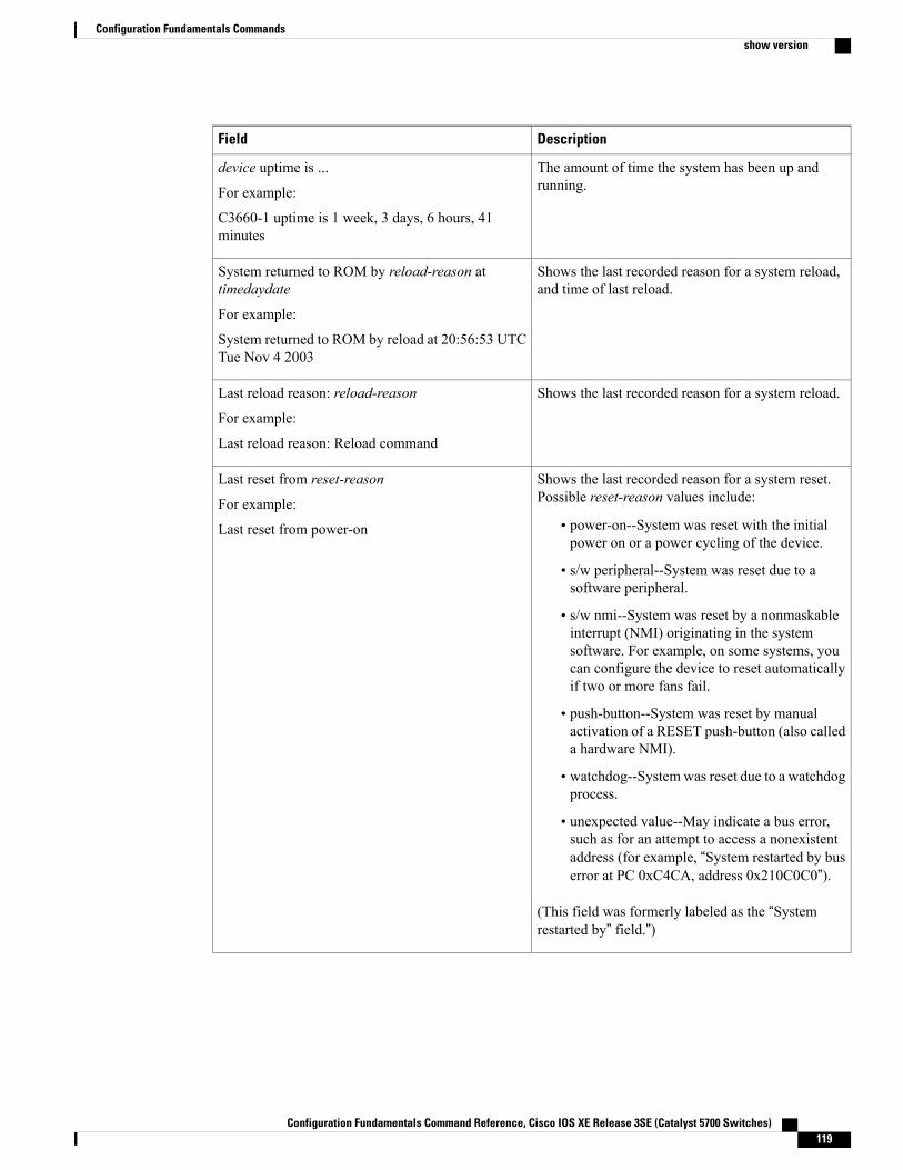
DescriptionField
The amount of time the system has been up andrunning.
device uptime is ...
For example:
C3660-1 uptime is 1 week, 3 days, 6 hours, 41minutes
Shows the last recorded reason for a system reload,and time of last reload.
System returned to ROM by reload-reason attimedaydate
For example:
System returned to ROM by reload at 20:56:53 UTCTue Nov 4 2003
Shows the last recorded reason for a system reload.Last reload reason: reload-reason
For example:
Last reload reason: Reload command
Shows the last recorded reason for a system reset.Possible reset-reason values include:
• power-on--System was reset with the initialpower on or a power cycling of the device.
• s/w peripheral--System was reset due to asoftware peripheral.
• s/w nmi--System was reset by a nonmaskableinterrupt (NMI) originating in the systemsoftware. For example, on some systems, youcan configure the device to reset automaticallyif two or more fans fail.
• push-button--System was reset by manualactivation of a RESET push-button (also calleda hardware NMI).
• watchdog--Systemwas reset due to a watchdogprocess.
• unexpected value--May indicate a bus error,such as for an attempt to access a nonexistentaddress (for example, “System restarted by buserror at PC 0xC4CA, address 0x210C0C0”).
(This field was formerly labeled as the “Systemrestarted by” field.”)
Last reset from reset-reason
For example:
Last reset from power-on
Configuration Fundamentals Command Reference, Cisco IOS XE Release 3SE (Catalyst 5700 Switches) 119
Configuration Fundamentals Commandsshow version
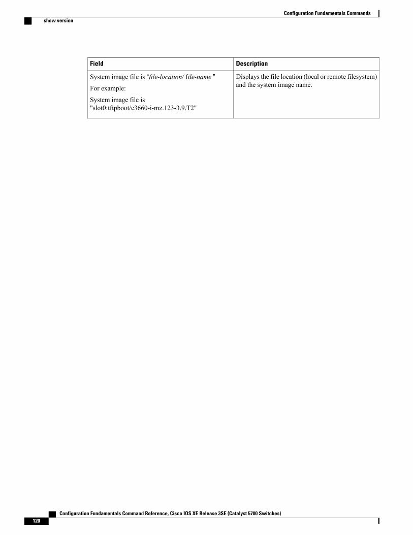
DescriptionField
Displays the file location (local or remote filesystem)and the system image name.
System image file is “file-location/ file-name ”For example:
System image file is"slot0:tftpboot/c3660-i-mz.123-3.9.T2"
Configuration Fundamentals Command Reference, Cisco IOS XE Release 3SE (Catalyst 5700 Switches)120
Configuration Fundamentals Commandsshow version
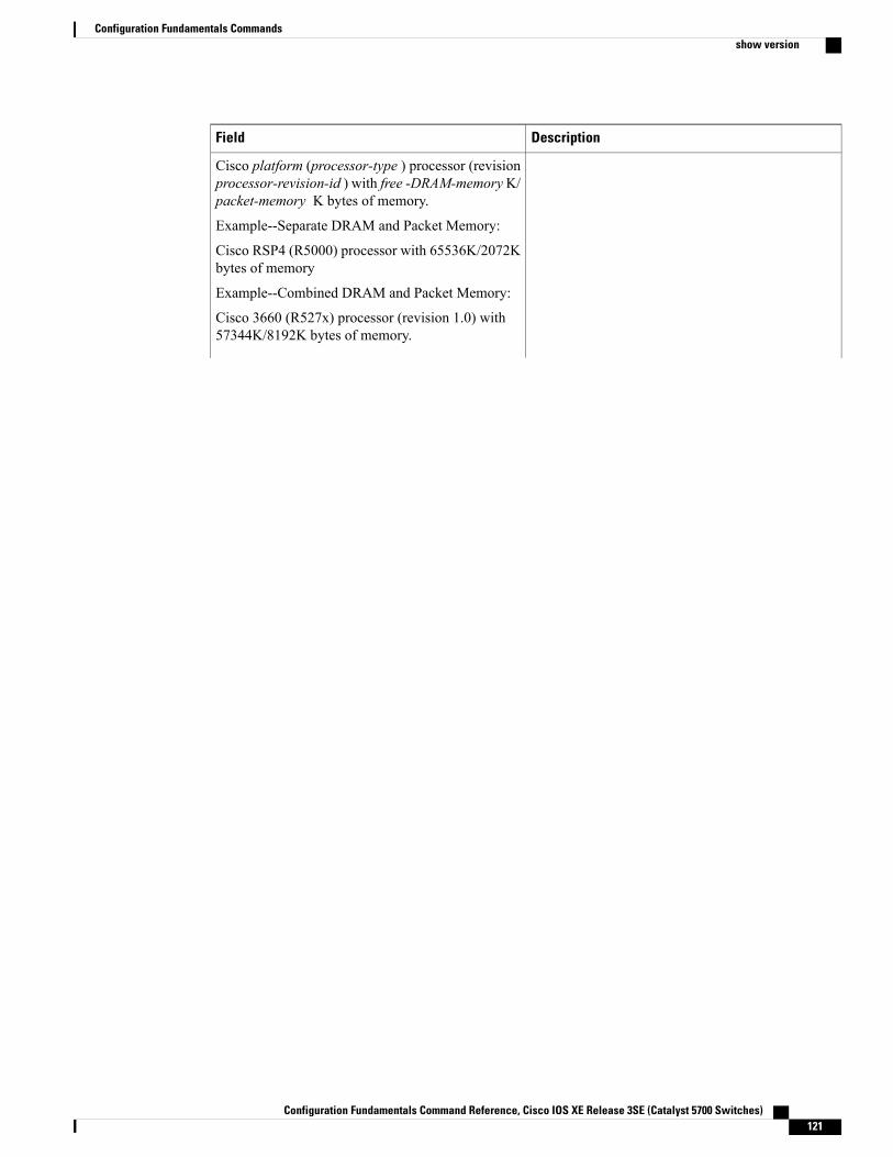
DescriptionField
Cisco platform (processor-type ) processor (revisionprocessor-revision-id ) with free -DRAM-memoryK/packet-memory K bytes of memory.
Example--Separate DRAM and Packet Memory:
Cisco RSP4 (R5000) processor with 65536K/2072Kbytes of memory
Example--Combined DRAM and Packet Memory:
Cisco 3660 (R527x) processor (revision 1.0) with57344K/8192K bytes of memory.
Configuration Fundamentals Command Reference, Cisco IOS XE Release 3SE (Catalyst 5700 Switches) 121
Configuration Fundamentals Commandsshow version
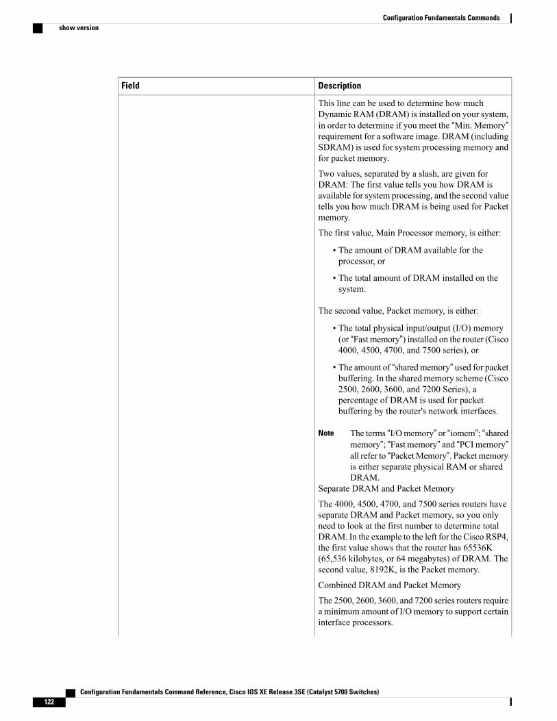
DescriptionField
This line can be used to determine how muchDynamic RAM (DRAM) is installed on your system,in order to determine if you meet the “Min. Memory”requirement for a software image. DRAM (includingSDRAM) is used for system processing memory andfor packet memory.
Two values, separated by a slash, are given forDRAM: The first value tells you how DRAM isavailable for system processing, and the second valuetells you how much DRAM is being used for Packetmemory.
The first value, Main Processor memory, is either:
• The amount of DRAM available for theprocessor, or
• The total amount of DRAM installed on thesystem.
The second value, Packet memory, is either:
• The total physical input/output (I/O) memory(or “Fast memory”) installed on the router (Cisco4000, 4500, 4700, and 7500 series), or
• The amount of “sharedmemory” used for packetbuffering. In the sharedmemory scheme (Cisco2500, 2600, 3600, and 7200 Series), apercentage of DRAM is used for packetbuffering by the router's network interfaces.
The terms “I/Omemory” or “iomem”; “sharedmemory”; “Fast memory” and “PCImemory”
Note
all refer to “PacketMemory”. Packetmemoryis either separate physical RAM or sharedDRAM.
Separate DRAM and Packet Memory
The 4000, 4500, 4700, and 7500 series routers haveseparate DRAM and Packet memory, so you onlyneed to look at the first number to determine totalDRAM. In the example to the left for the Cisco RSP4,the first value shows that the router has 65536K(65,536 kilobytes, or 64 megabytes) of DRAM. Thesecond value, 8192K, is the Packet memory.
Combined DRAM and Packet Memory
The 2500, 2600, 3600, and 7200 series routers requirea minimum amount of I/Omemory to support certaininterface processors.
Configuration Fundamentals Command Reference, Cisco IOS XE Release 3SE (Catalyst 5700 Switches)122
Configuration Fundamentals Commandsshow version
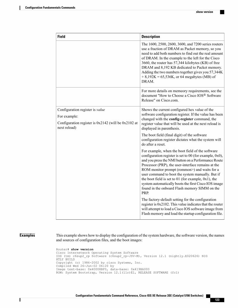
DescriptionField
The 1600, 2500, 2600, 3600, and 7200 series routersuse a fraction of DRAM as Packet memory, so youneed to add both numbers to find out the real amountof DRAM. In the example to the left for the Cisco3660, the router has 57,344 kilobytes (KB) of freeDRAM and 8,192 KB dedicated to Packet memory.Adding the two numbers together gives you 57,344K+ 8,192K = 65,536K, or 64 megabytes (MB) ofDRAM.
For more details on memeory requirements, see thedocument "How to Choose a Cisco IOS® SoftwareRelease" on Cisco.com.
Shows the current configured hex value of thesoftware configuration register. If the value has beenchanged with the config-register command, theregister value that will be used at the next reload isdisplayed in parenthesis.
The boot field (final digit) of the softwareconfiguration register dictates what the system willdo after a reset.
For example, when the boot field of the softwareconfiguration register is set to 00 (for example, 0x0),and you press the NMI button on a Performance RouteProcessor (PRP), the user-interface remains at theROM monitor prompt (rommon>) and waits for auser command to boot the system manually. But ifthe boot field is set to 01 (for example, 0x1), thesystem automatically boots the first Cisco IOS imagefound in the onboard Flash memory SIMM on thePRP.
The factory-default setting for the configurationregister is 0x2102. This value indicates that the routerwill attempt to load a Cisco IOS software image fromFlash memory and load the startup configuration file.
Configuration register is value
For example:
Configuration register is 0x2142 (will be 0x2102 atnext reload)
Examples This example shows how to display the configuration of the system hardware, the software version, the namesand sources of configuration files, and the boot images:
Router# show versionCisco Internetwork Operating System SoftwareIOS (tm) c6sup2_rp Software (c6sup2_rp-JSV-M), Version 12.1 (nightly.E020626) NIGHTLY BUILDCopyright (c) 1986-2002 by cisco Systems, Inc.Compiled Wed 26-Jun-02 06:20 byImage text-base: 0x40008BF0, data-base: 0x419BA000ROM: System Bootstrap, Version 12.1(11r)E1, RELEASE SOFTWARE (fc1)
Configuration Fundamentals Command Reference, Cisco IOS XE Release 3SE (Catalyst 5700 Switches) 123
Configuration Fundamentals Commandsshow version
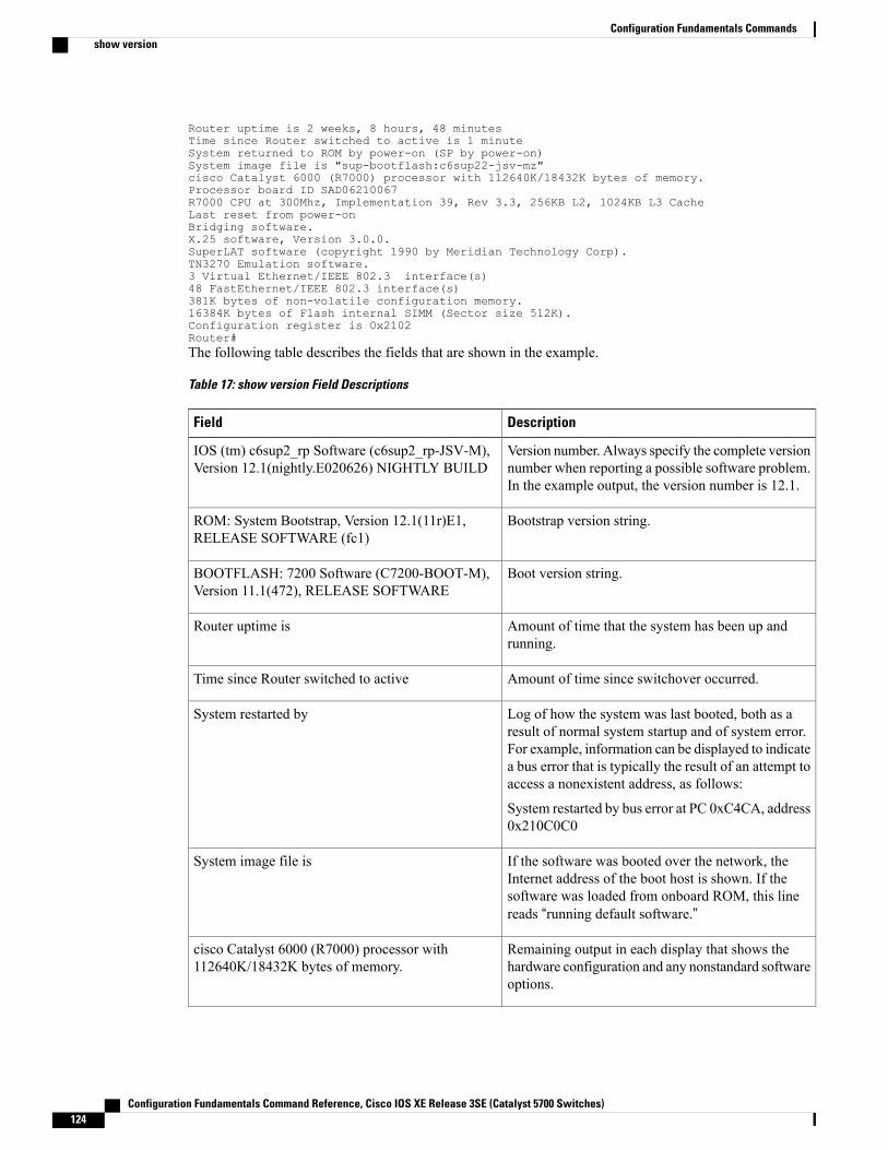
Router uptime is 2 weeks, 8 hours, 48 minutesTime since Router switched to active is 1 minuteSystem returned to ROM by power-on (SP by power-on)System image file is "sup-bootflash:c6sup22-jsv-mz"cisco Catalyst 6000 (R7000) processor with 112640K/18432K bytes of memory.Processor board ID SAD06210067R7000 CPU at 300Mhz, Implementation 39, Rev 3.3, 256KB L2, 1024KB L3 CacheLast reset from power-onBridging software.X.25 software, Version 3.0.0.SuperLAT software (copyright 1990 by Meridian Technology Corp).TN3270 Emulation software.3 Virtual Ethernet/IEEE 802.3 interface(s)48 FastEthernet/IEEE 802.3 interface(s)381K bytes of non-volatile configuration memory.16384K bytes of Flash internal SIMM (Sector size 512K).Configuration register is 0x2102Router#The following table describes the fields that are shown in the example.
Table 17: show version Field Descriptions
DescriptionField
Version number. Always specify the complete versionnumber when reporting a possible software problem.In the example output, the version number is 12.1.
IOS (tm) c6sup2_rp Software (c6sup2_rp-JSV-M),Version 12.1(nightly.E020626) NIGHTLY BUILD
Bootstrap version string.ROM: System Bootstrap, Version 12.1(11r)E1,RELEASE SOFTWARE (fc1)
Boot version string.BOOTFLASH: 7200 Software (C7200-BOOT-M),Version 11.1(472), RELEASE SOFTWARE
Amount of time that the system has been up andrunning.
Router uptime is
Amount of time since switchover occurred.Time since Router switched to active
Log of how the system was last booted, both as aresult of normal system startup and of system error.For example, information can be displayed to indicatea bus error that is typically the result of an attempt toaccess a nonexistent address, as follows:
System restarted by bus error at PC 0xC4CA, address0x210C0C0
System restarted by
If the software was booted over the network, theInternet address of the boot host is shown. If thesoftware was loaded from onboard ROM, this linereads “running default software.”
System image file is
Remaining output in each display that shows thehardware configuration and any nonstandard softwareoptions.
cisco Catalyst 6000 (R7000) processor with112640K/18432K bytes of memory.
Configuration Fundamentals Command Reference, Cisco IOS XE Release 3SE (Catalyst 5700 Switches)124
Configuration Fundamentals Commandsshow version
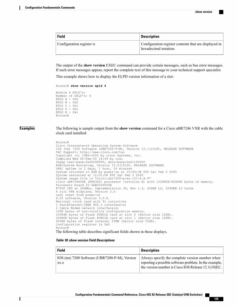
DescriptionField
Configuration register contents that are displayed inhexadecimal notation.
Configuration register is
The output of the show version EXEC command can provide certain messages, such as bus error messages.If such error messages appear, report the complete text of this message to your technical support specialist.
This example shows how to display the ELPD version information of a slot:
Router# show version epld 4
Module 4 EPLD's:Number of EPLD's: 6EPLD A : 0x5EPLD B : 0x2EPLD C : 0x1EPLD D : 0x1EPLD E : 0x1Router#
Examples The following is sample output from the show version command for a Cisco uBR7246 VXR with the cableclock card installed:
Router#Cisco Internetwork Operating System SoftwareIOS (tm) 7200 Software (UBR7200-P-M), Version 12.1(10)EC, RELEASE SOFTWARETAC Support: http://www.cisco.com/tacCopyright (c) 1986-2000 by cisco Systems, Inc.Compiled Wed 02-Feb-00 16:49 by ccaiImage text-base:0x60008900, data-base:0x61192000ROM:System Bootstrap, Version 12.0(15)SC, RELEASE SOFTWAREVXR1 uptime is 2 days, 1 hour, 24 minutesSystem returned to ROM by power-on at 10:54:38 PST Sat Feb 5 2000System restarted at 11:01:08 PST Sat Feb 5 2000System image file is "slot1:ubr7200-p-mz.121-0.8.T"cisco uBR7246VXR (NPE300) processor (revision B) with 122880K/40960K bytes of memory.Processor board ID SAB0329005NR7000 CPU at 262Mhz, Implementation 39, Rev 1.0, 256KB L2, 2048KB L3 Cache6 slot VXR midplane, Version 2.0Last reset from power-onX.25 software, Version 3.0.0.National clock card with T1 controller1 FastEthernet/IEEE 802.3 interface(s)2 Cable Modem network interface(s)125K bytes of non-volatile configuration memory.16384K bytes of Flash PCMCIA card at slot 0 (Sector size 128K).20480K bytes of Flash PCMCIA card at slot 1 (Sector size 128K).4096K bytes of Flash internal SIMM (Sector size 256K).Configuration register is 0x0Router#The following table describes significant fields shown in these displays.
Table 18: show version Field Descriptions
DescriptionField
Always specify the complete version number whenreporting a possible software problem. In the example,the version number is Cisco IOS Release 12.1(10)EC.
IOS (tm) 7200 Software (UBR7200-P-M), Versionxx.x
Configuration Fundamentals Command Reference, Cisco IOS XE Release 3SE (Catalyst 5700 Switches) 125
Configuration Fundamentals Commandsshow version
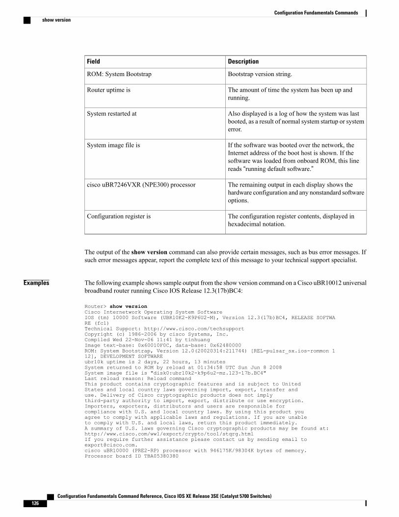
DescriptionField
Bootstrap version string.ROM: System Bootstrap
The amount of time the system has been up andrunning.
Router uptime is
Also displayed is a log of how the system was lastbooted, as a result of normal system startup or systemerror.
System restarted at
If the software was booted over the network, theInternet address of the boot host is shown. If thesoftware was loaded from onboard ROM, this linereads “running default software.”
System image file is
The remaining output in each display shows thehardware configuration and any nonstandard softwareoptions.
cisco uBR7246VXR (NPE300) processor
The configuration register contents, displayed inhexadecimal notation.
Configuration register is
The output of the show version command can also provide certain messages, such as bus error messages. Ifsuch error messages appear, report the complete text of this message to your technical support specialist.
Examples The following example shows sample output from the show version command on a Cisco uBR10012 universalbroadband router running Cisco IOS Release 12.3(17b)BC4:
Router> show versionCisco Internetwork Operating System SoftwareIOS (tm) 10000 Software (UBR10K2-K9P6U2-M), Version 12.3(17b)BC4, RELEASE SOFTWARE (fc1)Technical Support: http://www.cisco.com/techsupportCopyright (c) 1986-2006 by cisco Systems, Inc.Compiled Wed 22-Nov-06 11:41 by tinhuangImage text-base: 0x60010F0C, data-base: 0x62480000ROM: System Bootstrap, Version 12.0(20020314:211744) [REL-pulsar_sx.ios-rommon 112], DEVELOPMENT SOFTWAREubr10k uptime is 2 days, 22 hours, 13 minutesSystem returned to ROM by reload at 01:34:58 UTC Sun Jun 8 2008System image file is "disk0:ubr10k2-k9p6u2-mz.123-17b.BC4"Last reload reason: Reload commandThis product contains cryptographic features and is subject to UnitedStates and local country laws governing import, export, transfer anduse. Delivery of Cisco cryptographic products does not implythird-party authority to import, export, distribute or use encryption.Importers, exporters, distributors and users are responsible forcompliance with U.S. and local country laws. By using this product youagree to comply with applicable laws and regulations. If you are unableto comply with U.S. and local laws, return this product immediately.A summary of U.S. laws governing Cisco cryptographic products may be found at:http://www.cisco.com/wwl/export/crypto/tool/stqrg.htmlIf you require further assistance please contact us by sending email [email protected] uBR10000 (PRE2-RP) processor with 946175K/98304K bytes of memory.Processor board ID TBA05380380
Configuration Fundamentals Command Reference, Cisco IOS XE Release 3SE (Catalyst 5700 Switches)126
Configuration Fundamentals Commandsshow version
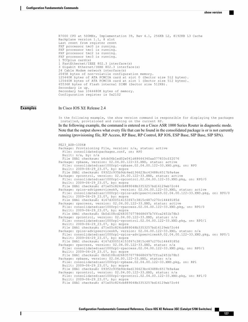
R7000 CPU at 500MHz, Implementation 39, Rev 4.1, 256KB L2, 8192KB L3 CacheBackplane version 1.1, 8 slotLast reset from register resetPXF processor tmc0 is running.PXF processor tmc1 is running.PXF processor tmc2 is running.PXF processor tmc3 is running.1 TCCplus card(s)1 FastEthernet/IEEE 802.3 interface(s)3 Gigabit Ethernet/IEEE 802.3 interface(s)24 Cable Modem network interface(s)2045K bytes of non-volatile configuration memory.125440K bytes of ATA PCMCIA card at slot 0 (Sector size 512 bytes).125440K bytes of ATA PCMCIA card at slot 1 (Sector size 512 bytes).65536K bytes of Flash internal SIMM (Sector size 512KB).Secondary is up.Secondary has 1044480K bytes of memory.Configuration register is 0x2102
Examples In Cisco IOS XE Release 2.4
In the following example, the show version command is responsible for displaying the packagesinstalled, provisioned and running on the current RP.In the following example, the command is entered on a Cisco ASR 1000 Series Router in diagnostic mode.Note that the output shows what every file that can be found in the consolidated package is or is not currentlyrunning (provisioning file, RP Access, RP Base, RP Control, RP IOS, ESP Base, SIP Base, SIP SPA).
PE23_ASR-1006#Package: Provisioning File, version: n/a, status: activeFile: consolidated:packages.conf, on: RP0Built: n/a, by: n/aFile SHA1 checksum: b6cb06b1ed02e041d48644340aa077833cff2076
Package: rpbase, version: 02.04.00.122-33.XND, status: activeFile: consolidated:asr1000rp1-rpbase.02.04.00.122-33.XND.pkg, on: RP0Built: 2009-06-29_23.07, by: mcpreFile SHA1 checksum: 093f2c935b9dc4ed136623bc43488c6517b9a4ae
Package: rpcontrol, version: 02.04.00.122-33.XND, status: activeFile: consolidated:asr1000rp1-rpcontrol.02.04.00.122-33.XND.pkg, on: RP0/0Built: 2009-06-29_23.07, by: mcpreFile SHA1 checksum: d71e05c824cb889048b3353257bd16129eb72c44
Package: rpios-advipservicesk9, version: 02.04.00.122-33.XND, status: activeFile: consolidated:asr1000rp1-rpios-advipservicesk9.02.04.00.122-33.XND.pkg, on: RP0/0Built: 2009-06-29_23.07, by: mcpreFile SHA1 checksum: 4167d300514153f67c3815c487c270c14449185d
Package: rpaccess, version: 02.04.00.122-33.XND, status: activeFile: consolidated:asr1000rp1-rpaccess.02.04.00.122-33.XND.pkg, on: RP0/0Built: 2009-06-29_23.07, by: mcpreFile SHA1 checksum: 0b0d108cd2683570778668697b7ffca2451b78b3
Package: rpcontrol, version: 02.04.00.122-33.XND, status: n/aFile: consolidated:asr1000rp1-rpcontrol.02.04.00.122-33.XND.pkg, on: RP0/1Built: 2009-06-29_23.07, by: mcpreFile SHA1 checksum: d71e05c824cb889048b3353257bd16129eb72c44
Package: rpios-advipservicesk9, version: 02.04.00.122-33.XND, status: n/aFile: consolidated:asr1000rp1-rpios-advipservicesk9.02.04.00.122-33.XND.pkg, on: RP0/1Built: 2009-06-29_23.07, by: mcpreFile SHA1 checksum: 4167d300514153f67c3815c487c270c14449185d
Package: rpaccess, version: 02.04.00.122-33.XND, status: n/aFile: consolidated:asr1000rp1-rpaccess.02.04.00.122-33.XND.pkg, on: RP0/1Built: 2009-06-29_23.07, by: mcpreFile SHA1 checksum: 0b0d108cd2683570778668697b7ffca2451b78b3
Package: rpbase, version: 02.04.00.122-33.XND, status: n/aFile: consolidated:asr1000rp1-rpbase.02.04.00.122-33.XND.pkg, on: RP1Built: 2009-06-29_23.07, by: mcpreFile SHA1 checksum: 093f2c935b9dc4ed136623bc43488c6517b9a4ae
Package: rpcontrol, version: 02.04.00.122-33.XND, status: n/aFile: consolidated:asr1000rp1-rpcontrol.02.04.00.122-33.XND.pkg, on: RP1/0Built: 2009-06-29_23.07, by: mcpreFile SHA1 checksum: d71e05c824cb889048b3353257bd16129eb72c44
Configuration Fundamentals Command Reference, Cisco IOS XE Release 3SE (Catalyst 5700 Switches) 127
Configuration Fundamentals Commandsshow version
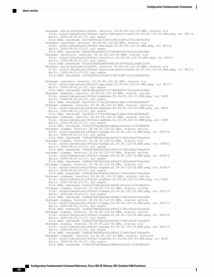
Package: rpios-advipservicesk9, version: 02.04.00.122-33.XND, status: n/aFile: consolidated:asr1000rp1-rpios-advipservicesk9.02.04.00.122-33.XND.pkg, on: RP1/0Built: 2009-06-29_23.07, by: mcpreFile SHA1 checksum: 4167d300514153f67c3815c487c270c14449185d
Package: rpaccess, version: 02.04.00.122-33.XND, status: n/aFile: consolidated:asr1000rp1-rpaccess.02.04.00.122-33.XND.pkg, on: RP1/0Built: 2009-06-29_23.07, by: mcpreFile SHA1 checksum: 0b0d108cd2683570778668697b7ffca2451b78b3
Package: rpcontrol, version: 02.04.00.122-33.XND, status: n/aFile: consolidated:asr1000rp1-rpcontrol.02.04.00.122-33.XND.pkg, on: RP1/1Built: 2009-06-29_23.07, by: mcpreFile SHA1 checksum: d71e05c824cb889048b3353257bd16129eb72c44
Package: rpios-advipservicesk9, version: 02.04.00.122-33.XND, status: n/aFile: consolidated:asr1000rp1-rpios-advipservicesk9.02.04.00.122-33.XND.pkg, on: RP1/1Built: 2009-06-29_23.07, by: mcpreFile SHA1 checksum: 4167d300514153f67c3815c487c270c14449185d
Package: rpaccess, version: 02.04.00.122-33.XND, status: n/aFile: consolidated:asr1000rp1-rpaccess.02.04.00.122-33.XND.pkg, on: RP1/1Built: 2009-06-29_23.07, by: mcpreFile SHA1 checksum: 0b0d108cd2683570778668697b7ffca2451b78b3
Package: espbase, version: 02.04.00.122-33.XND, status: activeFile: consolidated:asr1000rp1-espbase.02.04.00.122-33.XND.pkg, on: ESP0Built: 2009-06-29_23.07, by: mcpreFile SHA1 checksum: 3ae9255c7272a30f5dae319dec109acd29d9ae87
Package: espbase, version: 02.04.00.122-33.XND, status: inactiveFile: consolidated:asr1000rp1-espbase.02.04.00.122-33.XND.pkg, on: ESP1Built: 2009-06-29_23.07, by: mcpreFile SHA1 checksum: 3ae9255c7272a30f5dae319dec109acd29d9ae87
Package: sipbase, version: 02.04.00.122-33.XND, status: activeFile: consolidated:asr1000rp1-sipbase.02.04.00.122-33.XND.pkg, on: SIP0Built: 2009-06-29_23.07, by: mcpreFile SHA1 checksum: fc6e41d7de2ded3a16b6dc7e5e3a1151b788d254
Package: sipspa, version: 02.04.00.122-33.XND, status: activeFile: consolidated:asr1000rp1-sipspa.02.04.00.122-33.XND.pkg, on: SIP0/0Built: 2009-06-29_23.07, by: mcpreFile SHA1 checksum: 24fb5b788582e062c900e2713b5c56a2704ca836
Package: sipspa, version: 02.04.00.122-33.XND, status: n/aFile: consolidated:asr1000rp1-sipspa.02.04.00.122-33.XND.pkg, on: SIP0/1Built: 2009-06-29_23.07, by: mcpreFile SHA1 checksum: 24fb5b788582e062c900e2713b5c56a2704ca836
Package: sipspa, version: 02.04.00.122-33.XND, status: activeFile: consolidated:asr1000rp1-sipspa.02.04.00.122-33.XND.pkg, on: SIP0/2Built: 2009-06-29_23.07, by: mcpreFile SHA1 checksum: 24fb5b788582e062c900e2713b5c56a2704ca836
Package: sipspa, version: 02.04.00.122-33.XND, status: n/aFile: consolidated:asr1000rp1-sipspa.02.04.00.122-33.XND.pkg, on: SIP0/3Built: 2009-06-29_23.07, by: mcpreFile SHA1 checksum: 24fb5b788582e062c900e2713b5c56a2704ca836
Package: sipbase, version: 02.04.00.122-33.XND, status: activeFile: consolidated:asr1000rp1-sipbase.02.04.00.122-33.XND.pkg, on: SIP1Built: 2009-06-29_23.07, by: mcpreFile SHA1 checksum: fc6e41d7de2ded3a16b6dc7e5e3a1151b788d254
Package: sipspa, version: 02.04.00.122-33.XND, status: activeFile: consolidated:asr1000rp1-sipspa.02.04.00.122-33.XND.pkg, on: SIP1/0Built: 2009-06-29_23.07, by: mcpreFile SHA1 checksum: 24fb5b788582e062c900e2713b5c56a2704ca836
Package: sipspa, version: 02.04.00.122-33.XND, status: activeFile: consolidated:asr1000rp1-sipspa.02.04.00.122-33.XND.pkg, on: SIP1/1Built: 2009-06-29_23.07, by: mcpreFile SHA1 checksum: 24fb5b788582e062c900e2713b5c56a2704ca836
Package: sipspa, version: 02.04.00.122-33.XND, status: activeFile: consolidated:asr1000rp1-sipspa.02.04.00.122-33.XND.pkg, on: SIP1/2Built: 2009-06-29_23.07, by: mcpreFile SHA1 checksum: 24fb5b788582e062c900e2713b5c56a2704ca836
Package: sipspa, version: 02.04.00.122-33.XND, status: n/aFile: consolidated:asr1000rp1-sipspa.02.04.00.122-33.XND.pkg, on: SIP1/3Built: 2009-06-29_23.07, by: mcpreFile SHA1 checksum: 24fb5b788582e062c900e2713b5c56a2704ca836
Package: sipbase, version: 02.04.00.122-33.XND, status: inactiveFile: consolidated:asr1000rp1-sipbase.02.04.00.122-33.XND.pkg, on: SIP2Built: 2009-06-29_23.07, by: mcpreFile SHA1 checksum: fc6e41d7de2ded3a16b6dc7e5e3a1151b788d254
Configuration Fundamentals Command Reference, Cisco IOS XE Release 3SE (Catalyst 5700 Switches)128
Configuration Fundamentals Commandsshow version
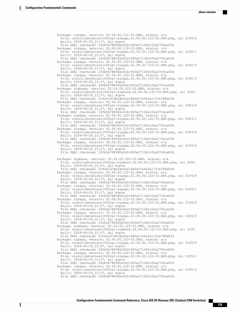
Package: sipspa, version: 02.04.00.122-33.XND, status: n/aFile: consolidated:asr1000rp1-sipspa.02.04.00.122-33.XND.pkg, on: SIP2/0Built: 2009-06-29_23.07, by: mcpreFile SHA1 checksum: 24fb5b788582e062c900e2713b5c56a2704ca836
Package: sipspa, version: 02.04.00.122-33.XND, status: n/aFile: consolidated:asr1000rp1-sipspa.02.04.00.122-33.XND.pkg, on: SIP2/1Built: 2009-06-29_23.07, by: mcpreFile SHA1 checksum: 24fb5b788582e062c900e2713b5c56a2704ca836
Package: sipspa, version: 02.04.00.122-33.XND, status: n/aFile: consolidated:asr1000rp1-sipspa.02.04.00.122-33.XND.pkg, on: SIP2/2Built: 2009-06-29_23.07, by: mcpreFile SHA1 checksum: 24fb5b788582e062c900e2713b5c56a2704ca836
Package: sipspa, version: 02.04.00.122-33.XND, status: n/aFile: consolidated:asr1000rp1-sipspa.02.04.00.122-33.XND.pkg, on: SIP2/3Built: 2009-06-29_23.07, by: mcpreFile SHA1 checksum: 24fb5b788582e062c900e2713b5c56a2704ca836
Package: sipbase, version: 02.04.00.122-33.XND, status: n/aFile: consolidated:asr1000rp1-sipbase.02.04.00.122-33.XND.pkg, on: SIP3Built: 2009-06-29_23.07, by: mcpreFile SHA1 checksum: fc6e41d7de2ded3a16b6dc7e5e3a1151b788d254
Package: sipspa, version: 02.04.00.122-33.XND, status: n/aFile: consolidated:asr1000rp1-sipspa.02.04.00.122-33.XND.pkg, on: SIP3/0Built: 2009-06-29_23.07, by: mcpreFile SHA1 checksum: 24fb5b788582e062c900e2713b5c56a2704ca836
Package: sipspa, version: 02.04.00.122-33.XND, status: n/aFile: consolidated:asr1000rp1-sipspa.02.04.00.122-33.XND.pkg, on: SIP3/1Built: 2009-06-29_23.07, by: mcpreFile SHA1 checksum: 24fb5b788582e062c900e2713b5c56a2704ca836
Package: sipspa, version: 02.04.00.122-33.XND, status: n/aFile: consolidated:asr1000rp1-sipspa.02.04.00.122-33.XND.pkg, on: SIP3/2Built: 2009-06-29_23.07, by: mcpreFile SHA1 checksum: 24fb5b788582e062c900e2713b5c56a2704ca836
Package: sipspa, version: 02.04.00.122-33.XND, status: n/aFile: consolidated:asr1000rp1-sipspa.02.04.00.122-33.XND.pkg, on: SIP3/3Built: 2009-06-29_23.07, by: mcpreFile SHA1 checksum: 24fb5b788582e062c900e2713b5c56a2704ca836
Package: sipbase, version: 02.04.00.122-33.XND, status: n/aFile: consolidated:asr1000rp1-sipbase.02.04.00.122-33.XND.pkg, on: SIP4Built: 2009-06-29_23.07, by: mcpreFile SHA1 checksum: fc6e41d7de2ded3a16b6dc7e5e3a1151b788d254
Package: sipspa, version: 02.04.00.122-33.XND, status: n/aFile: consolidated:asr1000rp1-sipspa.02.04.00.122-33.XND.pkg, on: SIP4/0Built: 2009-06-29_23.07, by: mcpreFile SHA1 checksum: 24fb5b788582e062c900e2713b5c56a2704ca836
Package: sipspa, version: 02.04.00.122-33.XND, status: n/aFile: consolidated:asr1000rp1-sipspa.02.04.00.122-33.XND.pkg, on: SIP4/1Built: 2009-06-29_23.07, by: mcpreFile SHA1 checksum: 24fb5b788582e062c900e2713b5c56a2704ca836
Package: sipspa, version: 02.04.00.122-33.XND, status: n/aFile: consolidated:asr1000rp1-sipspa.02.04.00.122-33.XND.pkg, on: SIP4/2Built: 2009-06-29_23.07, by: mcpreFile SHA1 checksum: 24fb5b788582e062c900e2713b5c56a2704ca836
Package: sipspa, version: 02.04.00.122-33.XND, status: n/aFile: consolidated:asr1000rp1-sipspa.02.04.00.122-33.XND.pkg, on: SIP4/3Built: 2009-06-29_23.07, by: mcpreFile SHA1 checksum: 24fb5b788582e062c900e2713b5c56a2704ca836
Package: sipbase, version: 02.04.00.122-33.XND, status: n/aFile: consolidated:asr1000rp1-sipbase.02.04.00.122-33.XND.pkg, on: SIP5Built: 2009-06-29_23.07, by: mcpreFile SHA1 checksum: fc6e41d7de2ded3a16b6dc7e5e3a1151b788d254
Package: sipspa, version: 02.04.00.122-33.XND, status: n/aFile: consolidated:asr1000rp1-sipspa.02.04.00.122-33.XND.pkg, on: SIP5/0Built: 2009-06-29_23.07, by: mcpreFile SHA1 checksum: 24fb5b788582e062c900e2713b5c56a2704ca836
Package: sipspa, version: 02.04.00.122-33.XND, status: n/aFile: consolidated:asr1000rp1-sipspa.02.04.00.122-33.XND.pkg, on: SIP5/1Built: 2009-06-29_23.07, by: mcpreFile SHA1 checksum: 24fb5b788582e062c900e2713b5c56a2704ca836
Package: sipspa, version: 02.04.00.122-33.XND, status: n/aFile: consolidated:asr1000rp1-sipspa.02.04.00.122-33.XND.pkg, on: SIP5/2Built: 2009-06-29_23.07, by: mcpreFile SHA1 checksum: 24fb5b788582e062c900e2713b5c56a2704ca836
Configuration Fundamentals Command Reference, Cisco IOS XE Release 3SE (Catalyst 5700 Switches) 129
Configuration Fundamentals Commandsshow version
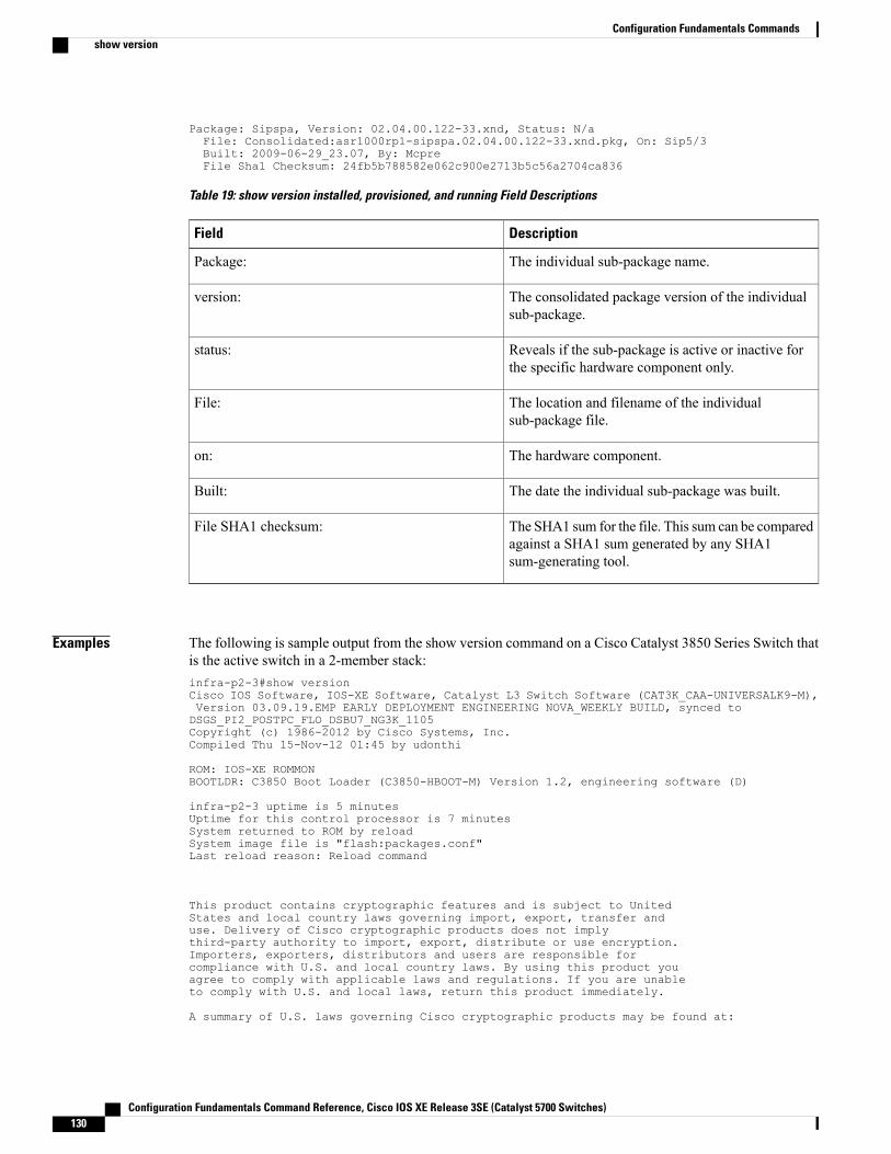
Package: Sipspa, Version: 02.04.00.122-33.xnd, Status: N/aFile: Consolidated:asr1000rp1-sipspa.02.04.00.122-33.xnd.pkg, On: Sip5/3Built: 2009-06-29_23.07, By: McpreFile Sha1 Checksum: 24fb5b788582e062c900e2713b5c56a2704ca836
Table 19: show version installed, provisioned, and running Field Descriptions
DescriptionField
The individual sub-package name.Package:
The consolidated package version of the individualsub-package.
version:
Reveals if the sub-package is active or inactive forthe specific hardware component only.
status:
The location and filename of the individualsub-package file.
File:
The hardware component.on:
The date the individual sub-package was built.Built:
The SHA1 sum for the file. This sum can be comparedagainst a SHA1 sum generated by any SHA1sum-generating tool.
File SHA1 checksum:
Examples The following is sample output from the show version command on a Cisco Catalyst 3850 Series Switch thatis the active switch in a 2-member stack:infra-p2-3#show versionCisco IOS Software, IOS-XE Software, Catalyst L3 Switch Software (CAT3K_CAA-UNIVERSALK9-M),Version 03.09.19.EMP EARLY DEPLOYMENT ENGINEERING NOVA_WEEKLY BUILD, synced toDSGS_PI2_POSTPC_FLO_DSBU7_NG3K_1105Copyright (c) 1986-2012 by Cisco Systems, Inc.Compiled Thu 15-Nov-12 01:45 by udonthi
ROM: IOS-XE ROMMONBOOTLDR: C3850 Boot Loader (C3850-HBOOT-M) Version 1.2, engineering software (D)
infra-p2-3 uptime is 5 minutesUptime for this control processor is 7 minutesSystem returned to ROM by reloadSystem image file is "flash:packages.conf"Last reload reason: Reload command
This product contains cryptographic features and is subject to UnitedStates and local country laws governing import, export, transfer anduse. Delivery of Cisco cryptographic products does not implythird-party authority to import, export, distribute or use encryption.Importers, exporters, distributors and users are responsible forcompliance with U.S. and local country laws. By using this product youagree to comply with applicable laws and regulations. If you are unableto comply with U.S. and local laws, return this product immediately.
A summary of U.S. laws governing Cisco cryptographic products may be found at:
Configuration Fundamentals Command Reference, Cisco IOS XE Release 3SE (Catalyst 5700 Switches)130
Configuration Fundamentals Commandsshow version
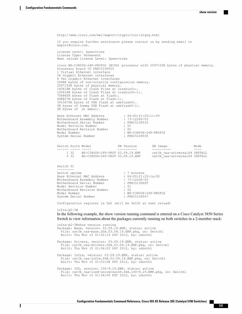
http://www.cisco.com/wwl/export/crypto/tool/stqrg.html
If you require further assistance please contact us by sending email [email protected].
License Level: IpservicesLicense Type: PermanentNext reload license Level: Ipservices
cisco WS-C3850X-24P-PROTO2 (MIPS) processor with 2097152K bytes of physical memory.Processor board ID FHH1515P03Y1 Virtual Ethernet interface56 Gigabit Ethernet interfaces8 Ten Gigabit Ethernet interfaces2048K bytes of non-volatile configuration memory.2097152K bytes of physical memory.160618K bytes of Crash Files at crashinfo:.160618K bytes of Crash Files at crashinfo-1:.706860K bytes of Flash at flash:.698827K bytes of Flash at flash-1:.3915670K bytes of USB Flash at usbflash0:.0K bytes of Dummy USB Flash at usbflash0-1:.0K bytes of at webui:.
Base Ethernet MAC Address : 64:00:f1:25:11:00Motherboard Assembly Number : 73-12240-03Motherboard Serial Number : FHH15130010Model Revision Number : 01Motherboard Revision Number : 02Model Number : WS-C3850X-24P-PROTO2System Serial Number : FHH1515P03Y
Switch Ports Model SW Version SW Image Mode------ ----- ----- ---------- ---------- ----
1 32 WS-C3850X-24P-PROT 03.09.19.EMP cat3k_caa-universalk9 INSTALL2 32 WS-C3850X-24P-PROT 03.09.19.EMP cat3k_caa-universalk9 INSTALL
Switch 01---------Switch uptime : 7 minutesBase Ethernet MAC Address : 64:00:f1:25:1a:00Motherboard Assembly Number : 73-12240-03Motherboard Serial Number : FHH1513000TModel Revision Number : 01Motherboard Revision Number : 02Model Number : WS-C3850X-24P-PROTO2System Serial Number : FHH1515P047
Configuration register is 0x2 (will be 0x102 at next reload)
infra-p2-3#In the following example, the show version running command is entered on a Cisco Catalyst 3850 SeriesSwitch to view information about the packages currently running on both switches in a 2-member stack:infra-p2-3#show version runningPackage: Base, version: 03.09.19.EMP, status: activeFile: cat3k_caa-base.SSA.03.09.19.EMP.pkg, on: Switch1Built: Thu Nov 15 01:52:19 PST 2012, by: udonthi
Package: Drivers, version: 03.09.19.EMP, status: activeFile: cat3k_caa-drivers.SSA.03.09.19.EMP.pkg, on: Switch1Built: Thu Nov 15 01:54:53 PST 2012, by: udonthi
Package: Infra, version: 03.09.19.EMP, status: activeFile: cat3k_caa-infra.SSA.03.09.19.EMP.pkg, on: Switch1Built: Thu Nov 15 01:53:08 PST 2012, by: udonthi
Package: IOS, version: 150-9.19.EMP, status: activeFile: cat3k_caa-iosd-universalk9.SSA.150-9.19.EMP.pkg, on: Switch1Built: Thu Nov 15 01:54:09 PST 2012, by: udonthi
Configuration Fundamentals Command Reference, Cisco IOS XE Release 3SE (Catalyst 5700 Switches) 131
Configuration Fundamentals Commandsshow version
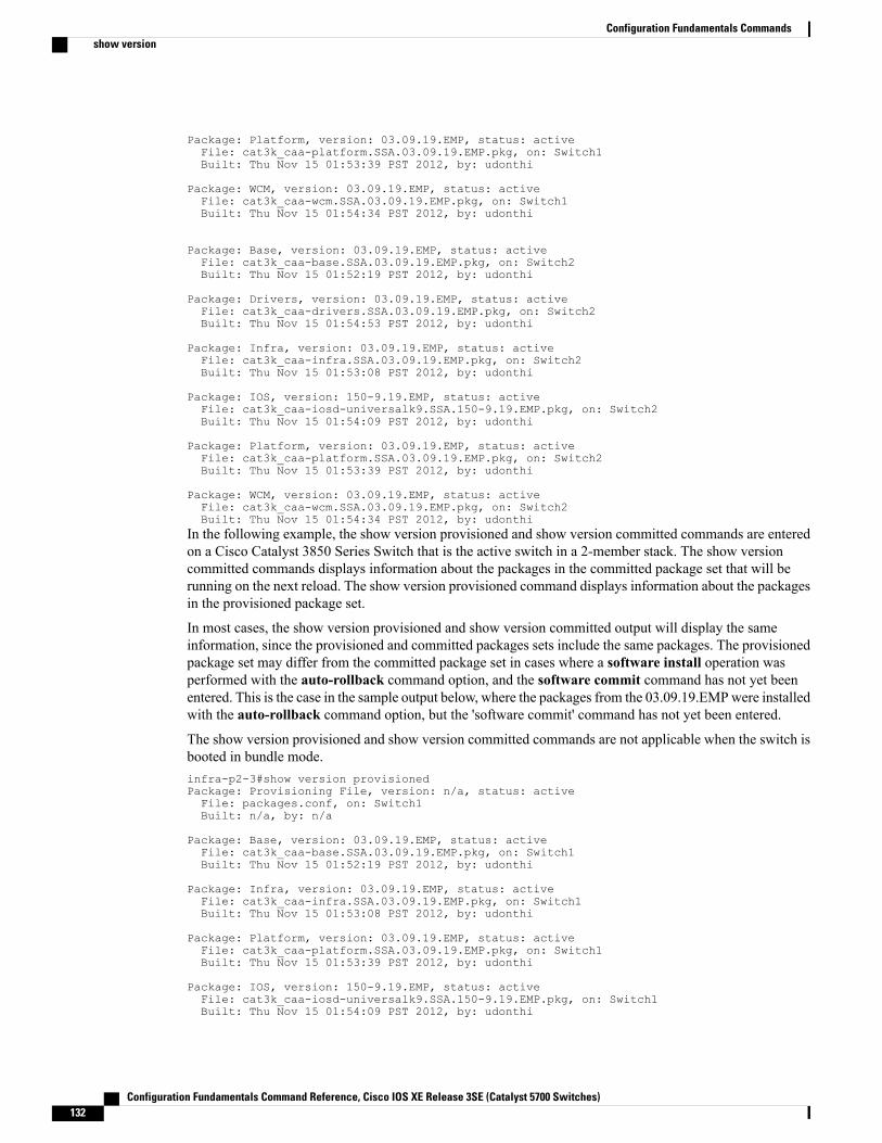
Package: Platform, version: 03.09.19.EMP, status: activeFile: cat3k_caa-platform.SSA.03.09.19.EMP.pkg, on: Switch1Built: Thu Nov 15 01:53:39 PST 2012, by: udonthi
Package: WCM, version: 03.09.19.EMP, status: activeFile: cat3k_caa-wcm.SSA.03.09.19.EMP.pkg, on: Switch1Built: Thu Nov 15 01:54:34 PST 2012, by: udonthi
Package: Base, version: 03.09.19.EMP, status: activeFile: cat3k_caa-base.SSA.03.09.19.EMP.pkg, on: Switch2Built: Thu Nov 15 01:52:19 PST 2012, by: udonthi
Package: Drivers, version: 03.09.19.EMP, status: activeFile: cat3k_caa-drivers.SSA.03.09.19.EMP.pkg, on: Switch2Built: Thu Nov 15 01:54:53 PST 2012, by: udonthi
Package: Infra, version: 03.09.19.EMP, status: activeFile: cat3k_caa-infra.SSA.03.09.19.EMP.pkg, on: Switch2Built: Thu Nov 15 01:53:08 PST 2012, by: udonthi
Package: IOS, version: 150-9.19.EMP, status: activeFile: cat3k_caa-iosd-universalk9.SSA.150-9.19.EMP.pkg, on: Switch2Built: Thu Nov 15 01:54:09 PST 2012, by: udonthi
Package: Platform, version: 03.09.19.EMP, status: activeFile: cat3k_caa-platform.SSA.03.09.19.EMP.pkg, on: Switch2Built: Thu Nov 15 01:53:39 PST 2012, by: udonthi
Package: WCM, version: 03.09.19.EMP, status: activeFile: cat3k_caa-wcm.SSA.03.09.19.EMP.pkg, on: Switch2Built: Thu Nov 15 01:54:34 PST 2012, by: udonthi
In the following example, the show version provisioned and show version committed commands are enteredon a Cisco Catalyst 3850 Series Switch that is the active switch in a 2-member stack. The show versioncommitted commands displays information about the packages in the committed package set that will berunning on the next reload. The show version provisioned command displays information about the packagesin the provisioned package set.
In most cases, the show version provisioned and show version committed output will display the sameinformation, since the provisioned and committed packages sets include the same packages. The provisionedpackage set may differ from the committed package set in cases where a software install operation wasperformed with the auto-rollback command option, and the software commit command has not yet beenentered. This is the case in the sample output below, where the packages from the 03.09.19.EMPwere installedwith the auto-rollback command option, but the 'software commit' command has not yet been entered.
The show version provisioned and show version committed commands are not applicable when the switch isbooted in bundle mode.infra-p2-3#show version provisionedPackage: Provisioning File, version: n/a, status: activeFile: packages.conf, on: Switch1Built: n/a, by: n/a
Package: Base, version: 03.09.19.EMP, status: activeFile: cat3k_caa-base.SSA.03.09.19.EMP.pkg, on: Switch1Built: Thu Nov 15 01:52:19 PST 2012, by: udonthi
Package: Infra, version: 03.09.19.EMP, status: activeFile: cat3k_caa-infra.SSA.03.09.19.EMP.pkg, on: Switch1Built: Thu Nov 15 01:53:08 PST 2012, by: udonthi
Package: Platform, version: 03.09.19.EMP, status: activeFile: cat3k_caa-platform.SSA.03.09.19.EMP.pkg, on: Switch1Built: Thu Nov 15 01:53:39 PST 2012, by: udonthi
Package: IOS, version: 150-9.19.EMP, status: activeFile: cat3k_caa-iosd-universalk9.SSA.150-9.19.EMP.pkg, on: Switch1Built: Thu Nov 15 01:54:09 PST 2012, by: udonthi
Configuration Fundamentals Command Reference, Cisco IOS XE Release 3SE (Catalyst 5700 Switches)132
Configuration Fundamentals Commandsshow version
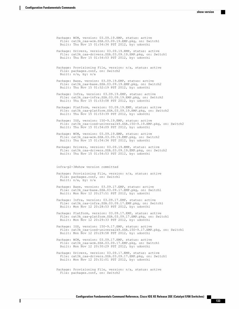
Package: WCM, version: 03.09.19.EMP, status: activeFile: cat3k_caa-wcm.SSA.03.09.19.EMP.pkg, on: Switch1Built: Thu Nov 15 01:54:34 PST 2012, by: udonthi
Package: Drivers, version: 03.09.19.EMP, status: activeFile: cat3k_caa-drivers.SSA.03.09.19.EMP.pkg, on: Switch1Built: Thu Nov 15 01:54:53 PST 2012, by: udonthi
Package: Provisioning File, version: n/a, status: activeFile: packages.conf, on: Switch2Built: n/a, by: n/a
Package: Base, version: 03.09.19.EMP, status: activeFile: cat3k_caa-base.SSA.03.09.19.EMP.pkg, on: Switch2Built: Thu Nov 15 01:52:19 PST 2012, by: udonthi
Package: Infra, version: 03.09.19.EMP, status: activeFile: cat3k_caa-infra.SSA.03.09.19.EMP.pkg, on: Switch2Built: Thu Nov 15 01:53:08 PST 2012, by: udonthi
Package: Platform, version: 03.09.19.EMP, status: activeFile: cat3k_caa-platform.SSA.03.09.19.EMP.pkg, on: Switch2Built: Thu Nov 15 01:53:39 PST 2012, by: udonthi
Package: IOS, version: 150-9.19.EMP, status: activeFile: cat3k_caa-iosd-universalk9.SSA.150-9.19.EMP.pkg, on: Switch2Built: Thu Nov 15 01:54:09 PST 2012, by: udonthi
Package: WCM, version: 03.09.19.EMP, status: activeFile: cat3k_caa-wcm.SSA.03.09.19.EMP.pkg, on: Switch2Built: Thu Nov 15 01:54:34 PST 2012, by: udonthi
Package: Drivers, version: 03.09.19.EMP, status: activeFile: cat3k_caa-drivers.SSA.03.09.19.EMP.pkg, on: Switch2Built: Thu Nov 15 01:54:53 PST 2012, by: udonthi
infra-p2-3#show version committed
Package: Provisioning File, version: n/a, status: activeFile: packages.conf, on: Switch1Built: n/a, by: n/a
Package: Base, version: 03.09.17.EMP, status: activeFile: cat3k_caa-base.SSA.03.09.17.EMP.pkg, on: Switch1Built: Mon Nov 12 20:27:51 PST 2012, by: udonthi
Package: Infra, version: 03.09.17.EMP, status: activeFile: cat3k_caa-infra.SSA.03.09.17.EMP.pkg, on: Switch1Built: Mon Nov 12 20:28:53 PST 2012, by: udonthi
Package: Platform, version: 03.09.17.EMP, status: activeFile: cat3k_caa-platform.SSA.03.09.17.EMP.pkg, on: Switch1Built: Mon Nov 12 20:29:33 PST 2012, by: udonthi
Package: IOS, version: 150-9.17.EMP, status: activeFile: cat3k_caa-iosd-universalk9.SSA.150-9.17.EMP.pkg, on: Switch1Built: Mon Nov 12 20:29:58 PST 2012, by: udonthi
Package: WCM, version: 03.09.17.EMP, status: activeFile: cat3k_caa-wcm.SSA.03.09.17.EMP.pkg, on: Switch1Built: Mon Nov 12 20:30:29 PST 2012, by: udonthi
Package: Drivers, version: 03.09.17.EMP, status: activeFile: cat3k_caa-drivers.SSA.03.09.17.EMP.pkg, on: Switch1Built: Mon Nov 12 20:31:01 PST 2012, by: udonthi
Package: Provisioning File, version: n/a, status: activeFile: packages.conf, on: Switch2
Configuration Fundamentals Command Reference, Cisco IOS XE Release 3SE (Catalyst 5700 Switches) 133
Configuration Fundamentals Commandsshow version

Built: n/a, by: n/a
Package: Base, version: 03.09.17.EMP, status: activeFile: cat3k_caa-base.SSA.03.09.17.EMP.pkg, on: Switch2Built: Mon Nov 12 20:27:51 PST 2012, by: udonthi
Package: Infra, version: 03.09.17.EMP, status: activeFile: cat3k_caa-infra.SSA.03.09.17.EMP.pkg, on: Switch2Built: Mon Nov 12 20:28:53 PST 2012, by: udonthi
Package: Platform, version: 03.09.17.EMP, status: activeFile: cat3k_caa-platform.SSA.03.09.17.EMP.pkg, on: Switch2Built: Mon Nov 12 20:29:33 PST 2012, by: udonthi
Package: IOS, version: 150-9.17.EMP, status: activeFile: cat3k_caa-iosd-universalk9.SSA.150-9.17.EMP.pkg, on: Switch2Built: Mon Nov 12 20:29:58 PST 2012, by: udonthi
Package: WCM, version: 03.09.17.EMP, status: activeFile: cat3k_caa-wcm.SSA.03.09.17.EMP.pkg, on: Switch2Built: Mon Nov 12 20:30:29 PST 2012, by: udonthi
Package: Drivers, version: 03.09.17.EMP, status: activeFile: cat3k_caa-drivers.SSA.03.09.17.EMP.pkg, on: Switch2Built: Mon Nov 12 20:31:01 PST 2012, by: udonthi
infra-p2-3#
Table 20: Table 5,Cisco Catalyst 3850 Series Switches and Cisco 5760 Series Wireless Controllers show version runningField Descriptions
DescriptionField
The individual sub-package name.Package:
The individual sub-package version.version:
Reveals if the package is active or inactive for thespecific Supervisor module.
status:
The filename of the individual package file.File:
The slot number of the Active or Standby Supervisorthat this package is running on.
on:
The date the individual package was built.Built:
Examples The following is sample output from the show version command on a Cisco Catalyst 4500e Series Switchrunning IOS XE software:Switch#show versionCisco IOS Software, IOS-XE Software, Catalyst 4500 L3 Switch Software(cat4500e-UNIVERSALK9-M), Experimental Version 3.1.0.SG[/nobackup/xxxx/cwab/build/arch_ppc/buildtree-ios/vob/ios/sys 100] Copyright (c)1986-2010 by Cisco Systems, Inc.Compiled Mon 19-Apr-10 09:19 by xxxx
Cisco IOS-XE software, Copyright (c) 2005-2010 by cisco Systems, Inc.
Configuration Fundamentals Command Reference, Cisco IOS XE Release 3SE (Catalyst 5700 Switches)134
Configuration Fundamentals Commandsshow version
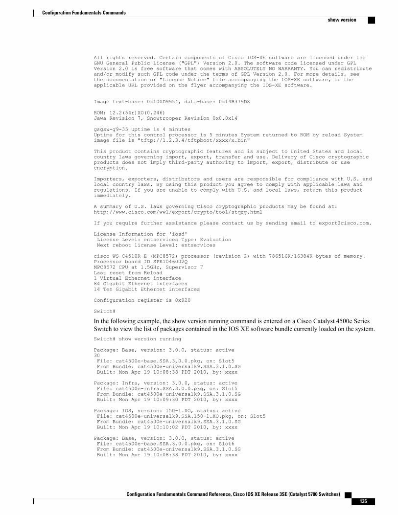
All rights reserved. Certain components of Cisco IOS-XE software are licensed under theGNU General Public License ("GPL") Version 2.0. The software code licensed under GPLVersion 2.0 is free software that comes with ABSOLUTELY NO WARRANTY. You can redistributeand/or modify such GPL code under the terms of GPL Version 2.0. For more details, seethe documentation or "License Notice" file accompanying the IOS-XE software, or theapplicable URL provided on the flyer accompanying the IOS-XE software.
Image text-base: 0x100D9954, data-base: 0x14B379D8
ROM: 12.2(54r)XO(0.246)Jawa Revision 7, Snowtrooper Revision 0x0.0x14
gsgsw-g9-35 uptime is 4 minutesUptime for this control processor is 5 minutes System returned to ROM by reload Systemimage file is "tftp://1.2.3.4/tftpboot/xxxx/x.bin"
This product contains cryptographic features and is subject to United States and localcountry laws governing import, export, transfer and use. Delivery of Cisco cryptographicproducts does not imply third-party authority to import, export, distribute or useencryption.
Importers, exporters, distributors and users are responsible for compliance with U.S. andlocal country laws. By using this product you agree to comply with applicable laws andregulations. If you are unable to comply with U.S. and local laws, return this productimmediately.
A summary of U.S. laws governing Cisco cryptographic products may be found at:http://www.cisco.com/wwl/export/crypto/tool/stqrg.html
If you require further assistance please contact us by sending email to [email protected].
License Information for 'iosd'License Level: entservices Type: EvaluationNext reboot license Level: entservices
cisco WS-C4510R-E (MPC8572) processor (revision 2) with 786516K/16384K bytes of memory.Processor board ID SPE1046002QMPC8572 CPU at 1.5GHz, Supervisor 7Last reset from Reload1 Virtual Ethernet interface84 Gigabit Ethernet interfaces14 Ten Gigabit Ethernet interfaces
Configuration register is 0x920
Switch#
In the following example, the show version running command is entered on a Cisco Catalyst 4500e SeriesSwitch to view the list of packages contained in the IOS XE software bundle currently loaded on the system.Switch# show version running
Package: Base, version: 3.0.0, status: active30File: cat4500e-base.SSA.3.0.0.pkg, on: Slot5From Bundle: cat4500e-universalk9.SSA.3.1.0.SGBuilt: Mon Apr 19 10:08:38 PDT 2010, by: xxxx
Package: Infra, version: 3.0.0, status: activeFile: cat4500e-infra.SSA.3.0.0.pkg, on: Slot5From Bundle: cat4500e-universalk9.SSA.3.1.0.SGBuilt: Mon Apr 19 10:09:30 PDT 2010, by: xxxx
Package: IOS, version: 150-1.XO, status: activeFile: cat4500e-universalk9.SSA.150-1.XO.pkg, on: Slot5From Bundle: cat4500e-universalk9.SSA.3.1.0.SGBuilt: Mon Apr 19 10:10:02 PDT 2010, by: xxxx
Package: Base, version: 3.0.0, status: activeFile: cat4500e-base.SSA.3.0.0.pkg, on: Slot6From Bundle: cat4500e-universalk9.SSA.3.1.0.SGBuilt: Mon Apr 19 10:08:38 PDT 2010, by: xxxx
Configuration Fundamentals Command Reference, Cisco IOS XE Release 3SE (Catalyst 5700 Switches) 135
Configuration Fundamentals Commandsshow version
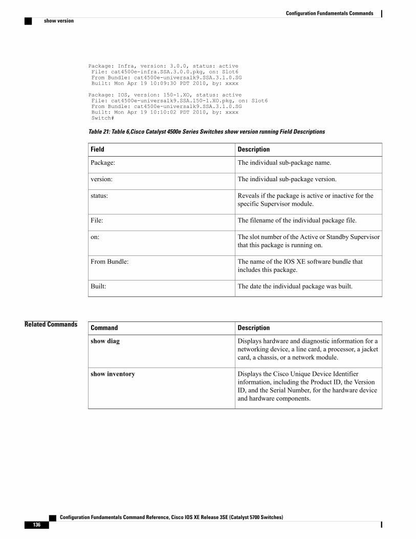
Package: Infra, version: 3.0.0, status: activeFile: cat4500e-infra.SSA.3.0.0.pkg, on: Slot6From Bundle: cat4500e-universalk9.SSA.3.1.0.SGBuilt: Mon Apr 19 10:09:30 PDT 2010, by: xxxx
Package: IOS, version: 150-1.XO, status: activeFile: cat4500e-universalk9.SSA.150-1.XO.pkg, on: Slot6From Bundle: cat4500e-universalk9.SSA.3.1.0.SGBuilt: Mon Apr 19 10:10:02 PDT 2010, by: xxxxSwitch#
Table 21: Table 6,Cisco Catalyst 4500e Series Switches show version running Field Descriptions
DescriptionField
The individual sub-package name.Package:
The individual sub-package version.version:
Reveals if the package is active or inactive for thespecific Supervisor module.
status:
The filename of the individual package file.File:
The slot number of the Active or Standby Supervisorthat this package is running on.
on:
The name of the IOS XE software bundle thatincludes this package.
From Bundle:
The date the individual package was built.Built:
Related Commands DescriptionCommand
Displays hardware and diagnostic information for anetworking device, a line card, a processor, a jacketcard, a chassis, or a network module.
show diag
Displays the Cisco Unique Device Identifierinformation, including the Product ID, the VersionID, and the Serial Number, for the hardware deviceand hardware components.
show inventory
Configuration Fundamentals Command Reference, Cisco IOS XE Release 3SE (Catalyst 5700 Switches)136
Configuration Fundamentals Commandsshow version
software auto-upgradeTo enable the user to initiate the auto-upgrade functionality in scenarios where the feature is disabled, use thesoftware auto-upgrade command in privileged EXEC mode or global configuration mode. To disable thisfunctionality, use the no form of this command.
software auto-upgrade enable | source url software-location
no software auto-upgrade enable | source url software-location
Syntax Description
Syntax Description Enables the auto-upgrade installation feature.enable
Configures software auto-upgrade source parameters.source
Provides the software location to install during auto-upgrades.url
Specifies a bin file to use to auto-upgrade a switch.software-location
Command Default This feature is disabled by default.
Command Modes Privileged EXEC (#)
Global configuration (config)
Command History ModificationRelease
This command was introduced.Cisco IOS XE Release 3.3SE
Usage Guidelines The software auto-upgrade command initiates the auto upgrade process if the switches are runningincompatible software or in an incompatible mode. If the software auto-upgrade enable command is notconfigured, auto-advise syslog messages are displayed.
The software auto-upgrade command is used in privileged EXEC mode to auto upgrade the incompatibleswitch. This command has no keywords. The software auto-upgrade command, determines the switchesthat are running incompatible software or running in an incompatible mode and initiates the auto upgradeprocess for each. If sufficient space is available in flash, the software auto-upgrade command in privilegedEXEC mode is invoked to auto-upgrade and reload the incompatible switch.
When the auto-upgrade functionality is enabled and the software auto-upgrade source url command isconfigured, active installer verifies that the specified software location exists and is valid for the platform.
Configuration Fundamentals Command Reference, Cisco IOS XE Release 3SE (Catalyst 5700 Switches) 137
Configuration Fundamentals Commandssoftware auto-upgrade
Examples The following example shows how to configure the software auto-upgrade command in privileged EXECmode.Device> enableDevice# software auto-upgrade
The following sample output shows the INFO level systemmessages displayed to the console by the auto-advisefeature when auto-upgrade is disabled.*Oct 18 11:09:47.005: %INSTALLER-6-AUTO_ADVISE_SW_INITIATED: 2 installer: Auto adviseinitiated for switch 1*Oct 18 11:09:47.005: %INSTALLER-6-AUTO_ADVISE_SW: 2 installer: Switch 1 running bundledsoftware has been added*Oct 18 11:09:47.005: %INSTALLER-6-AUTO_ADVISE_SW: 2 installer: to the stack that is runninginstalled software.*Oct 18 11:09:47.005: %INSTALLER-6-AUTO_ADVISE_SW: 2 installer: The 'software auto-upgrade'command can be used to*Oct 18 11:09:47.005: %INSTALLER-6-AUTO_ADVISE_SW: 2 installer: convert switch 1 to theinstalled running mode by*Oct 18 11:09:47.005: %INSTALLER-6-AUTO_ADVISE_SW: 2 installer: installing its runningsoftware
The following example shows how to configure the software auto-upgrade command in global configurationmode.Device> enableDevice# configure terminalDevice(config)# software auto-upgradeDevice(config)# software auto-upgrade enableDevice(config)# software auto-upgrade sourceDevice(config)# software auto-upgrade source url
The following sample output shows the INFO level system messages displayed to the console whenauto-upgrade is used to upgrade the incompatible switch in global configuration mode.infra-p2-3# show runn | include auto-upgradesoftware auto-upgrade source urltftp://172.19.211.47/cstohs/cat3k_caa-universalk9.SSA.05.00.1015.152-1.1015.binsoftware auto-upgrade enableinfra-p2-3#*Oct 18 16:14:41.782: %INSTALLER-6-AUTO_UPGRADE_SW_INITIATED: 2 installer: Auto upgradeinitiated for switch 1*Oct 18 16:14:45.824: %INSTALLER-6-AUTO_UPGRADE_SW: 2 installer: Upgrading switch 1 withconfigured auto upgrade*Oct 18 16:14:45.824: %INSTALLER-6-AUTO_UPGRADE_SW: 2 installer: bundletftp://172.19.211.47/cstohs/cat3k_caa-universalk9.SSA.05.00.1015.152-1.1015.bin*Oct 18 16:20:53.546: %INSTALLER-6-AUTO_UPGRADE_SW: 2 installer: Finished installingsoftware on switch 1*Oct 18 16:20:53.546: %INSTALLER-6-AUTO_UPGRADE_SW: 2 installer: Reloading switch 1 tocomplete the auto upgrade
Related Commands DescriptionCommand
Removes all packages and provisioning files that areno longer in use.
software clean
Commits a package set that was installed using theauto-rollback command option of the softwareinstall command.
software commit
Configuration Fundamentals Command Reference, Cisco IOS XE Release 3SE (Catalyst 5700 Switches)138
Configuration Fundamentals Commandssoftware auto-upgrade
software cleanTo remove any and all packages and provisioning files that are no longer in use, use the software cleancommand in Privileged EXEC mode.
software clean[filefile url][switchnodes][verbose]
Syntax Description Full path to wildcarded filename(s). Optional whenrunning in installedmode.When no command optionsare specified, all unused package, bundle andprovisioning files in the current boot directory willbe cleaned.
filefile url
(optional) Specifies which switch(es) should performthe clean operation using '1,2,4' and/or '2-4' notation.Default is all switches in the stack.
switchnodes
(optional) provides some additional info in the logfiles .
verbose
Command Default No software package(s) will be cleaned by default.
Command Modes Privileged EXEC
Command History ModificationRelease
Command introduced.IOS XE 3.2.0 SE
This command was integrated.Cisco IOS XE Release 3.3SE
Usage Guidelines If no specific file to be deleted is indicated, the installer will search for unused packages and provisioningfiles on a given media device (eg., bootflash:, usb0: etc) to delete. One or more nodes may be given.
With no options specified for software clean, all unused packages and provisioning files on the currentlybooted device will be cleaned. The currently booted device is where the committed packages.conf file resides.
Examples This example uses the 'software clean' command with no command options to clean the current boot directory,flash:, on a standalone switch that is running in installed mode.infra-p2-3#dir flash:Directory of flash:/
7378 -rwx 2097152 Nov 15 2012 09:45:11 +00:00 nvram_config
Configuration Fundamentals Command Reference, Cisco IOS XE Release 3SE (Catalyst 5700 Switches) 139
Configuration Fundamentals Commandssoftware clean
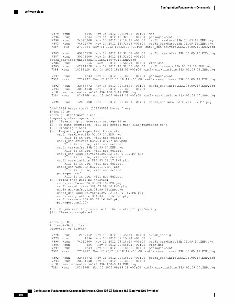
7379 drwx 4096 Nov 15 2012 09:19:24 +00:00 mnt7396 -rwx 1244 Nov 14 2012 18:32:55 +00:00 packages.conf.00-7390 -rwx 74390300 Nov 15 2012 09:18:17 +00:00 cat3k_caa-base.SSA.03.09.17.EMP.pkg7383 -rwx 74601776 Nov 14 2012 18:31:59 +00:00 cat3k_caa-base.SSA.03.09.16.EMD.pkg7384 -rwx 2732724 Nov 14 2012 18:32:08 +00:00 cat3k_caa-drivers.SSA.03.09.16.EMD.pkg
7385 -rwx 49886128 Nov 14 2012 18:32:02 +00:00 cat3k_caa-infra.SSA.03.09.16.EMD.pkg7387 -rwx 30579500 Nov 14 2012 18:32:05 +00:00cat3k_caa-iosd-universalk9.SSA.150-9.16.EMD.pkg7386 -rwx 556 Nov 9 2012 09:58:21 +00:00 vlan.dat7389 -rwx 62814928 Nov 14 2012 18:32:08 +00:00 cat3k_caa-wcm.SSA.03.09.16.EMD.pkg7388 -rwx 18193120 Nov 14 2012 18:32:03 +00:00 cat3k_caa-platform.SSA.03.09.16.EMD.pkg
7397 -rwx 1243 Nov 15 2012 09:18:55 +00:00 packages.conf7391 -rwx 2734772 Nov 15 2012 09:18:17 +00:00 cat3k_caa-drivers.SSA.03.09.17.EMP.pkg
7392 -rwx 32465772 Nov 15 2012 09:18:24 +00:00 cat3k_caa-infra.SSA.03.09.17.EMP.pkg7393 -rwx 30384940 Nov 15 2012 09:18:35 +00:00cat3k_caa-iosd-universalk9.SSA.150-9.17.EMP.pkg7394 -rwx 18143968 Nov 15 2012 09:18:39 +00:00 cat3k_caa-platform.SSA.03.09.17.EMP.pkg
7395 -rwx 62638800 Nov 15 2012 09:18:51 +00:00 cat3k_caa-wcm.SSA.03.09.17.EMP.pkg
712413184 bytes total (208535552 bytes free)infra-p2-3#infra-p2-3#software cleanPreparing clean operation ...[2]: Cleaning up unnecessary package files[2]: No path specified, will use booted path flash:packages.conf[2]: Cleaning flash:[2]: Preparing packages list to delete ...
cat3k_caa-base.SSA.03.09.17.EMP.pkgFile is in use, will not delete.
cat3k_caa-drivers.SSA.03.09.17.EMP.pkgFile is in use, will not delete.
cat3k_caa-infra.SSA.03.09.17.EMP.pkgFile is in use, will not delete.
cat3k_caa-iosd-universalk9.SSA.150-9.17.EMP.pkgFile is in use, will not delete.
cat3k_caa-platform.SSA.03.09.17.EMP.pkgFile is in use, will not delete.
cat3k_caa-wcm.SSA.03.09.17.EMP.pkgFile is in use, will not delete.
packages.confFile is in use, will not delete.
[2]: Files that will be deleted:cat3k_caa-base.SSA.03.09.16.EMD.pkgcat3k_caa-drivers.SSA.03.09.16.EMD.pkgcat3k_caa-infra.SSA.03.09.16.EMD.pkgcat3k_caa-iosd-universalk9.SSA.150-9.16.EMD.pkgcat3k_caa-platform.SSA.03.09.16.EMD.pkgcat3k_caa-wcm.SSA.03.09.16.EMD.pkgpackages.conf.00-
[2]: Do you want to proceed with the deletion? [yes/no]: y[2]: Clean up completed
infra-p2-3#infra-p2-3#dir flash:Directory of flash:/
7378 -rwx 2097152 Nov 15 2012 09:45:11 +00:00 nvram_config7379 drwx 4096 Nov 15 2012 09:19:24 +00:00 mnt7390 -rwx 74390300 Nov 15 2012 09:18:17 +00:00 cat3k_caa-base.SSA.03.09.17.EMP.pkg7386 -rwx 556 Nov 9 2012 09:58:21 +00:00 vlan.dat7397 -rwx 1243 Nov 15 2012 09:18:55 +00:00 packages.conf7391 -rwx 2734772 Nov 15 2012 09:18:17 +00:00 cat3k_caa-drivers.SSA.03.09.17.EMP.pkg
7392 -rwx 32465772 Nov 15 2012 09:18:24 +00:00 cat3k_caa-infra.SSA.03.09.17.EMP.pkg7393 -rwx 30384940 Nov 15 2012 09:18:35 +00:00cat3k_caa-iosd-universalk9.SSA.150-9.17.EMP.pkg7394 -rwx 18143968 Nov 15 2012 09:18:39 +00:00 cat3k_caa-platform.SSA.03.09.17.EMP.pkg
Configuration Fundamentals Command Reference, Cisco IOS XE Release 3SE (Catalyst 5700 Switches)140
Configuration Fundamentals Commandssoftware clean
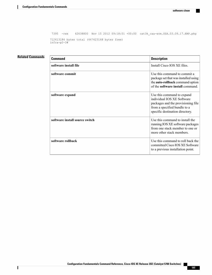
7395 -rwx 62638800 Nov 15 2012 09:18:51 +00:00 cat3k_caa-wcm.SSA.03.09.17.EMP.pkg
712413184 bytes total (447623168 bytes free)infra-p2-3#
Related Commands DescriptionCommand
Install Cisco IOS XE files.software install file
Use this command to commit apackage set that was installed usingthe auto-rollback command optionof the software install command.
software commit
Use this command to expandindividual IOS XE Softwarepackages and the provisioning filefrom a specified bundle to aspecific destination directory.
software expand
Use this command to install therunning IOSXE software packagesfrom one stack member to one ormore other stack members.
software install source switch
Use this command to roll back thecommitted Cisco IOSXE Softwareto a previous installation point.
software rollback
Configuration Fundamentals Command Reference, Cisco IOS XE Release 3SE (Catalyst 5700 Switches) 141
Configuration Fundamentals Commandssoftware clean
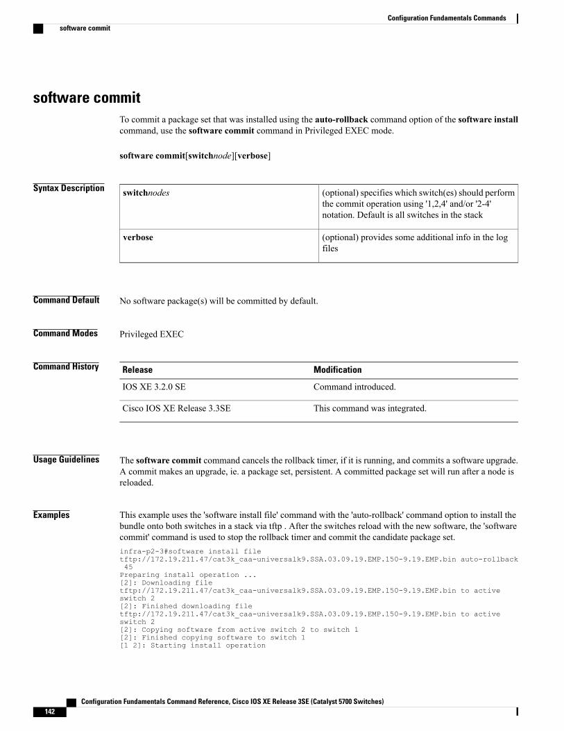
software commitTo commit a package set that was installed using the auto-rollback command option of the software installcommand, use the software commit command in Privileged EXEC mode.
software commit[switchnode][verbose]
Syntax Description (optional) specifies which switch(es) should performthe commit operation using '1,2,4' and/or '2-4'notation. Default is all switches in the stack
switchnodes
(optional) provides some additional info in the logfiles
verbose
Command Default No software package(s) will be committed by default.
Command Modes Privileged EXEC
Command History ModificationRelease
Command introduced.IOS XE 3.2.0 SE
This command was integrated.Cisco IOS XE Release 3.3SE
Usage Guidelines The software commit command cancels the rollback timer, if it is running, and commits a software upgrade.A commit makes an upgrade, ie. a package set, persistent. A committed package set will run after a node isreloaded.
Examples This example uses the 'software install file' command with the 'auto-rollback' command option to install thebundle onto both switches in a stack via tftp . After the switches reload with the new software, the 'softwarecommit' command is used to stop the rollback timer and commit the candidate package set.infra-p2-3#software install filetftp://172.19.211.47/cat3k_caa-universalk9.SSA.03.09.19.EMP.150-9.19.EMP.bin auto-rollback45Preparing install operation ...[2]: Downloading filetftp://172.19.211.47/cat3k_caa-universalk9.SSA.03.09.19.EMP.150-9.19.EMP.bin to activeswitch 2[2]: Finished downloading filetftp://172.19.211.47/cat3k_caa-universalk9.SSA.03.09.19.EMP.150-9.19.EMP.bin to activeswitch 2[2]: Copying software from active switch 2 to switch 1[2]: Finished copying software to switch 1[1 2]: Starting install operation
Configuration Fundamentals Command Reference, Cisco IOS XE Release 3SE (Catalyst 5700 Switches)142
Configuration Fundamentals Commandssoftware commit
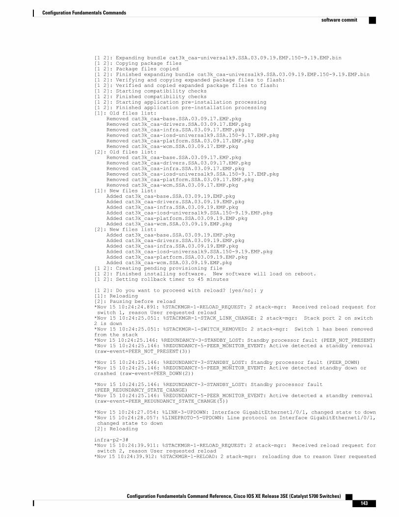
[1 2]: Expanding bundle cat3k_caa-universalk9.SSA.03.09.19.EMP.150-9.19.EMP.bin[1 2]: Copying package files[1 2]: Package files copied[1 2]: Finished expanding bundle cat3k_caa-universalk9.SSA.03.09.19.EMP.150-9.19.EMP.bin[1 2]: Verifying and copying expanded package files to flash:[1 2]: Verified and copied expanded package files to flash:[1 2]: Starting compatibility checks[1 2]: Finished compatibility checks[1 2]: Starting application pre-installation processing[1 2]: Finished application pre-installation processing[1]: Old files list:
Removed cat3k_caa-base.SSA.03.09.17.EMP.pkgRemoved cat3k_caa-drivers.SSA.03.09.17.EMP.pkgRemoved cat3k_caa-infra.SSA.03.09.17.EMP.pkgRemoved cat3k_caa-iosd-universalk9.SSA.150-9.17.EMP.pkgRemoved cat3k_caa-platform.SSA.03.09.17.EMP.pkgRemoved cat3k_caa-wcm.SSA.03.09.17.EMP.pkg
[2]: Old files list:Removed cat3k_caa-base.SSA.03.09.17.EMP.pkgRemoved cat3k_caa-drivers.SSA.03.09.17.EMP.pkgRemoved cat3k_caa-infra.SSA.03.09.17.EMP.pkgRemoved cat3k_caa-iosd-universalk9.SSA.150-9.17.EMP.pkgRemoved cat3k_caa-platform.SSA.03.09.17.EMP.pkgRemoved cat3k_caa-wcm.SSA.03.09.17.EMP.pkg
[1]: New files list:Added cat3k_caa-base.SSA.03.09.19.EMP.pkgAdded cat3k_caa-drivers.SSA.03.09.19.EMP.pkgAdded cat3k_caa-infra.SSA.03.09.19.EMP.pkgAdded cat3k_caa-iosd-universalk9.SSA.150-9.19.EMP.pkgAdded cat3k_caa-platform.SSA.03.09.19.EMP.pkgAdded cat3k_caa-wcm.SSA.03.09.19.EMP.pkg
[2]: New files list:Added cat3k_caa-base.SSA.03.09.19.EMP.pkgAdded cat3k_caa-drivers.SSA.03.09.19.EMP.pkgAdded cat3k_caa-infra.SSA.03.09.19.EMP.pkgAdded cat3k_caa-iosd-universalk9.SSA.150-9.19.EMP.pkgAdded cat3k_caa-platform.SSA.03.09.19.EMP.pkgAdded cat3k_caa-wcm.SSA.03.09.19.EMP.pkg
[1 2]: Creating pending provisioning file[1 2]: Finished installing software. New software will load on reboot.[1 2]: Setting rollback timer to 45 minutes
[1 2]: Do you want to proceed with reload? [yes/no]: y[1]: Reloading[2]: Pausing before reload*Nov 15 10:24:24.891: %STACKMGR-1-RELOAD_REQUEST: 2 stack-mgr: Received reload request forswitch 1, reason User requested reload*Nov 15 10:24:25.051: %STACKMGR-1-STACK_LINK_CHANGE: 2 stack-mgr: Stack port 2 on switch2 is down*Nov 15 10:24:25.051: %STACKMGR-1-SWITCH_REMOVED: 2 stack-mgr: Switch 1 has been removedfrom the stack*Nov 15 10:24:25.146: %REDUNDANCY-3-STANDBY_LOST: Standby processor fault (PEER_NOT_PRESENT)*Nov 15 10:24:25.146: %REDUNDANCY-5-PEER_MONITOR_EVENT: Active detected a standby removal(raw-event=PEER_NOT_PRESENT(3))
*Nov 15 10:24:25.146: %REDUNDANCY-3-STANDBY_LOST: Standby processor fault (PEER_DOWN)*Nov 15 10:24:25.146: %REDUNDANCY-5-PEER_MONITOR_EVENT: Active detected standby down orcrashed (raw-event=PEER_DOWN(2))
*Nov 15 10:24:25.146: %REDUNDANCY-3-STANDBY_LOST: Standby processor fault(PEER_REDUNDANCY_STATE_CHANGE)*Nov 15 10:24:25.146: %REDUNDANCY-5-PEER_MONITOR_EVENT: Active detected a standby removal(raw-event=PEER_REDUNDANCY_STATE_CHANGE(5))
*Nov 15 10:24:27.054: %LINK-3-UPDOWN: Interface GigabitEthernet1/0/1, changed state to down*Nov 15 10:24:28.057: %LINEPROTO-5-UPDOWN: Line protocol on Interface GigabitEthernet1/0/1,changed state to down[2]: Reloading
infra-p2-3#*Nov 15 10:24:39.911: %STACKMGR-1-RELOAD_REQUEST: 2 stack-mgr: Received reload request forswitch 2, reason User requested reload*Nov 15 10:24:39.912: %STACKMGR-1-RELOAD: 2 stack-mgr: reloading due to reason User requested
Configuration Fundamentals Command Reference, Cisco IOS XE Release 3SE (Catalyst 5700 Switches) 143
Configuration Fundamentals Commandssoftware commit
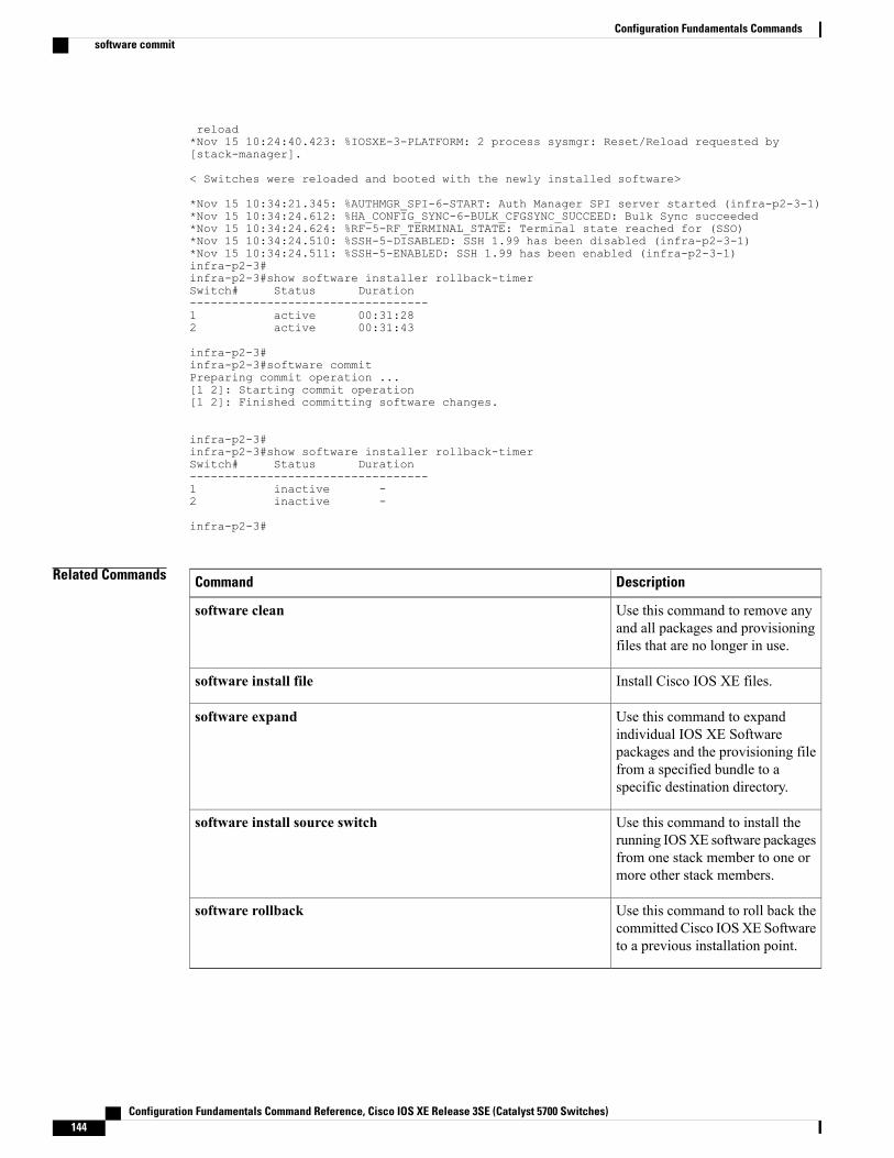
reload*Nov 15 10:24:40.423: %IOSXE-3-PLATFORM: 2 process sysmgr: Reset/Reload requested by[stack-manager].
< Switches were reloaded and booted with the newly installed software>
*Nov 15 10:34:21.345: %AUTHMGR_SPI-6-START: Auth Manager SPI server started (infra-p2-3-1)*Nov 15 10:34:24.612: %HA_CONFIG_SYNC-6-BULK_CFGSYNC_SUCCEED: Bulk Sync succeeded*Nov 15 10:34:24.624: %RF-5-RF_TERMINAL_STATE: Terminal state reached for (SSO)*Nov 15 10:34:24.510: %SSH-5-DISABLED: SSH 1.99 has been disabled (infra-p2-3-1)*Nov 15 10:34:24.511: %SSH-5-ENABLED: SSH 1.99 has been enabled (infra-p2-3-1)infra-p2-3#infra-p2-3#show software installer rollback-timerSwitch# Status Duration----------------------------------1 active 00:31:282 active 00:31:43
infra-p2-3#infra-p2-3#software commitPreparing commit operation ...[1 2]: Starting commit operation[1 2]: Finished committing software changes.
infra-p2-3#infra-p2-3#show software installer rollback-timerSwitch# Status Duration----------------------------------1 inactive -2 inactive -
infra-p2-3#
Related Commands DescriptionCommand
Use this command to remove anyand all packages and provisioningfiles that are no longer in use.
software clean
Install Cisco IOS XE files.software install file
Use this command to expandindividual IOS XE Softwarepackages and the provisioning filefrom a specified bundle to aspecific destination directory.
software expand
Use this command to install therunning IOSXE software packagesfrom one stack member to one ormore other stack members.
software install source switch
Use this command to roll back thecommitted Cisco IOSXE Softwareto a previous installation point.
software rollback
Configuration Fundamentals Command Reference, Cisco IOS XE Release 3SE (Catalyst 5700 Switches)144
Configuration Fundamentals Commandssoftware commit
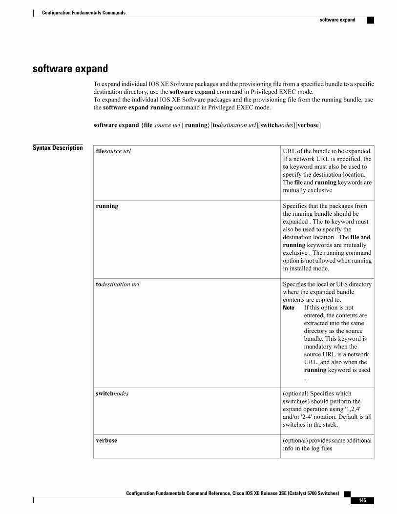
software expandTo expand individual IOS XE Software packages and the provisioning file from a specified bundle to a specificdestination directory, use the software expand command in Privileged EXEC mode.To expand the individual IOS XE Software packages and the provisioning file from the running bundle, usethe software expand running command in Privileged EXEC mode.
software expand {file source url | running}[todestination url][switchnodes][verbose]
Syntax Description URL of the bundle to be expanded.If a network URL is specified, theto keyword must also be used tospecify the destination location.The file and running keywords aremutually exclusive
filesource url
Specifies that the packages fromthe running bundle should beexpanded . The to keyword mustalso be used to specify thedestination location . The file andrunning keywords are mutuallyexclusive . The running commandoption is not allowedwhen runningin installed mode.
running
Specifies the local or UFS directorywhere the expanded bundlecontents are copied to.
If this option is notentered, the contents areextracted into the samedirectory as the sourcebundle. This keyword ismandatory when thesource URL is a networkURL, and also when therunning keyword is used.
Note
todestination url
(optional) Specifies whichswitch(es) should perform theexpand operation using '1,2,4'and/or '2-4' notation. Default is allswitches in the stack.
switchnodes
(optional) provides some additionalinfo in the log files
verbose
Configuration Fundamentals Command Reference, Cisco IOS XE Release 3SE (Catalyst 5700 Switches) 145
Configuration Fundamentals Commandssoftware expand
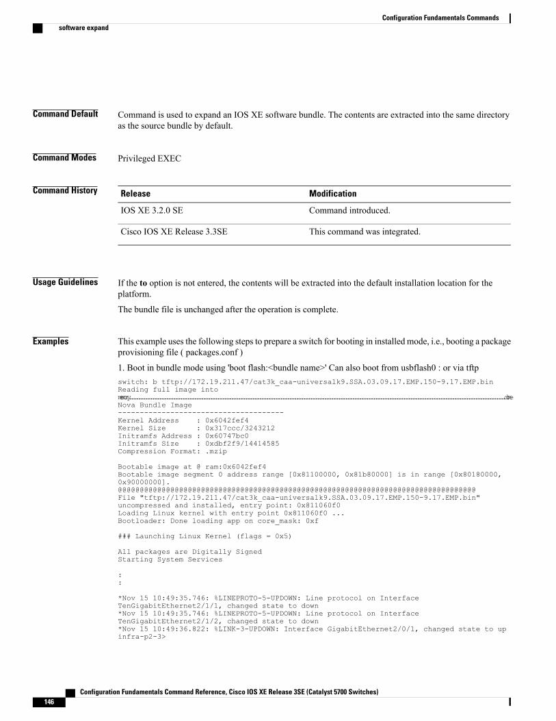
Command Default Command is used to expand an IOS XE software bundle. The contents are extracted into the same directoryas the source bundle by default.
Command Modes Privileged EXEC
Command History ModificationRelease
Command introduced.IOS XE 3.2.0 SE
This command was integrated.Cisco IOS XE Release 3.3SE
Usage Guidelines If the to option is not entered, the contents will be extracted into the default installation location for theplatform.
The bundle file is unchanged after the operation is complete.
Examples This example uses the following steps to prepare a switch for booting in installed mode, i.e., booting a packageprovisioning file ( packages.conf )
1. Boot in bundle mode using 'boot flash:<bundle name>' Can also boot from usbflash0 : or via tftpswitch: b tftp://172.19.211.47/cat3k_caa-universalk9.SSA.03.09.17.EMP.150-9.17.EMP.binReading full image intomemory......................................................................................................................................................................................................................doneNova Bundle Image--------------------------------------Kernel Address : 0x6042fef4Kernel Size : 0x317ccc/3243212Initramfs Address : 0x60747bc0Initramfs Size : 0xdbf2f9/14414585Compression Format: .mzip
Bootable image at @ ram:0x6042fef4Bootable image segment 0 address range [0x81100000, 0x81b80000] is in range [0x80180000,0x90000000].@@@@@@@@@@@@@@@@@@@@@@@@@@@@@@@@@@@@@@@@@@@@@@@@@@@@@@@@@@@@@@@@@@@@@@@@@@@@@@@@@@File "tftp://172.19.211.47/cat3k_caa-universalk9.SSA.03.09.17.EMP.150-9.17.EMP.bin"uncompressed and installed, entry point: 0x811060f0Loading Linux kernel with entry point 0x811060f0 ...Bootloader: Done loading app on core_mask: 0xf
### Launching Linux Kernel (flags = 0x5)
All packages are Digitally SignedStarting System Services
::
*Nov 15 10:49:35.746: %LINEPROTO-5-UPDOWN: Line protocol on InterfaceTenGigabitEthernet2/1/1, changed state to down*Nov 15 10:49:35.746: %LINEPROTO-5-UPDOWN: Line protocol on InterfaceTenGigabitEthernet2/1/2, changed state to down*Nov 15 10:49:36.822: %LINK-3-UPDOWN: Interface GigabitEthernet2/0/1, changed state to upinfra-p2-3>
Configuration Fundamentals Command Reference, Cisco IOS XE Release 3SE (Catalyst 5700 Switches)146
Configuration Fundamentals Commandssoftware expand
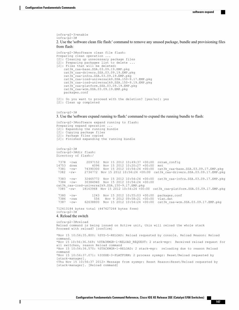
infra-p2-3>enableinfra-p2-3#2. Use the 'software clean file flash:' command to remove any unused package, bundle and provisioning filesfrom flash:infra-p2-3#software clean file flash:Preparing clean operation ...[2]: Cleaning up unnecessary package files[2]: Preparing packages list to delete ...[2]: Files that will be deleted:
cat3k_caa-base.SSA.03.09.19.EMP.pkgcat3k_caa-drivers.SSA.03.09.19.EMP.pkgcat3k_caa-infra.SSA.03.09.19.EMP.pkgcat3k_caa-iosd-universalk9.SSA.150-9.17.EMP.pkgcat3k_caa-iosd-universalk9.SSA.150-9.19.EMP.pkgcat3k_caa-platform.SSA.03.09.19.EMP.pkgcat3k_caa-wcm.SSA.03.09.19.EMP.pkgpackages.conf
[2]: Do you want to proceed with the deletion? [yes/no]: yes[2]: Clean up completed
infra-p2-3#3. Use the 'software expand running to flash:' command to expand the running bundle to flash:infra-p2-3#software expand running to flash:Preparing expand operation ...[2]: Expanding the running bundle[2]: Copying package files[2]: Package files copied[2]: Finished expanding the running bundle
infra-p2-3#infra-p2-3#dir flash:Directory of flash:/
7378 -rwx 2097152 Nov 15 2012 10:49:37 +00:00 nvram_config14753 drwx 4096 Nov 15 2012 10:20:27 +00:00 mnt7381 -rw- 74390300 Nov 15 2012 10:54:24 +00:00 cat3k_caa-base.SSA.03.09.17.EMP.pkg7382 -rw- 2734772 Nov 15 2012 10:54:24 +00:00 cat3k_caa-drivers.SSA.03.09.17.EMP.pkg
7383 -rw- 32465772 Nov 15 2012 10:54:24 +00:00 cat3k_caa-infra.SSA.03.09.17.EMP.pkg7384 -rw- 30384940 Nov 15 2012 10:54:24 +00:00cat3k_caa-iosd-universalk9.SSA.150-9.17.EMP.pkg7385 -rw- 18143968 Nov 15 2012 10:54:24 +00:00 cat3k_caa-platform.SSA.03.09.17.EMP.pkg
7380 -rw- 1243 Nov 15 2012 10:55:03 +00:00 packages.conf7386 -rwx 556 Nov 9 2012 09:58:21 +00:00 vlan.dat7387 -rw- 62638800 Nov 15 2012 10:54:24 +00:00 cat3k_caa-wcm.SSA.03.09.17.EMP.pkg
712413184 bytes total (447627264 bytes free)infra-p2-3#4. Reload the switchinfra-p2-3#reloadReload command is being issued on Active unit, this will reload the whole stackProceed with reload? [confirm]
*Nov 15 10:56:35.800: %SYS-5-RELOAD: Reload requested by console. Reload Reason: Reloadcommand.*Nov 15 10:56:36.569: %STACKMGR-1-RELOAD_REQUEST: 2 stack-mgr: Received reload request forall switches, reason Reload command*Nov 15 10:56:36.570: %STACKMGR-1-RELOAD: 2 stack-mgr: reloading due to reason Reloadcommand*Nov 15 10:56:37.071: %IOSXE-3-PLATFORM: 2 process sysmgr: Reset/Reload requested by[stack-manager].<Thu Nov 15 10:56:37 2012> Message from sysmgr: Reset Reason:Reset/Reload requested by[stack-manager]. [Reload command]
Configuration Fundamentals Command Reference, Cisco IOS XE Release 3SE (Catalyst 5700 Switches) 147
Configuration Fundamentals Commandssoftware expand
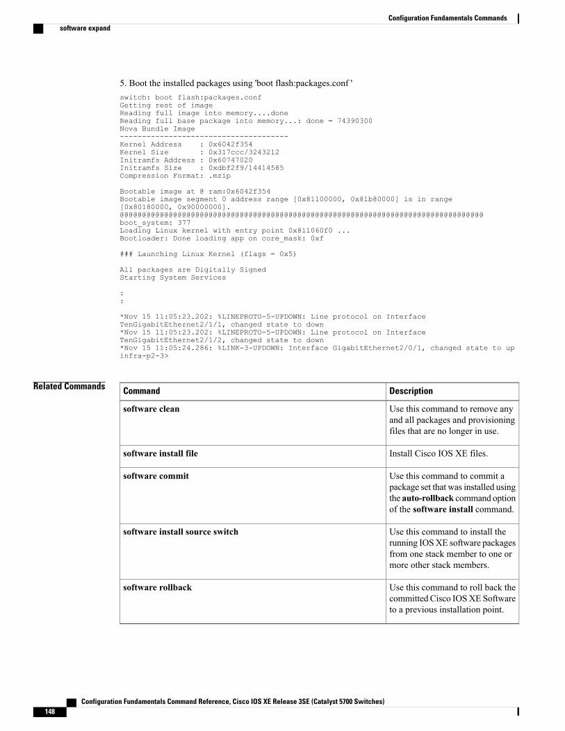
5. Boot the installed packages using 'boot flash:packages.conf 'switch: boot flash:packages.confGetting rest of imageReading full image into memory....doneReading full base package into memory...: done = 74390300Nova Bundle Image--------------------------------------Kernel Address : 0x6042f354Kernel Size : 0x317ccc/3243212Initramfs Address : 0x60747020Initramfs Size : 0xdbf2f9/14414585Compression Format: .mzip
Bootable image at @ ram:0x6042f354Bootable image segment 0 address range [0x81100000, 0x81b80000] is in range[0x80180000, 0x90000000].@@@@@@@@@@@@@@@@@@@@@@@@@@@@@@@@@@@@@@@@@@@@@@@@@@@@@@@@@@@@@@@@@@@@@@@@@@@@@@@@@@boot_system: 377Loading Linux kernel with entry point 0x811060f0 ...Bootloader: Done loading app on core_mask: 0xf
### Launching Linux Kernel (flags = 0x5)
All packages are Digitally SignedStarting System Services
::
*Nov 15 11:05:23.202: %LINEPROTO-5-UPDOWN: Line protocol on InterfaceTenGigabitEthernet2/1/1, changed state to down*Nov 15 11:05:23.202: %LINEPROTO-5-UPDOWN: Line protocol on InterfaceTenGigabitEthernet2/1/2, changed state to down*Nov 15 11:05:24.286: %LINK-3-UPDOWN: Interface GigabitEthernet2/0/1, changed state to upinfra-p2-3>
Related Commands DescriptionCommand
Use this command to remove anyand all packages and provisioningfiles that are no longer in use.
software clean
Install Cisco IOS XE files.software install file
Use this command to commit apackage set that was installed usingthe auto-rollback command optionof the software install command.
software commit
Use this command to install therunning IOSXE software packagesfrom one stack member to one ormore other stack members.
software install source switch
Use this command to roll back thecommitted Cisco IOSXE Softwareto a previous installation point.
software rollback
Configuration Fundamentals Command Reference, Cisco IOS XE Release 3SE (Catalyst 5700 Switches)148
Configuration Fundamentals Commandssoftware expand
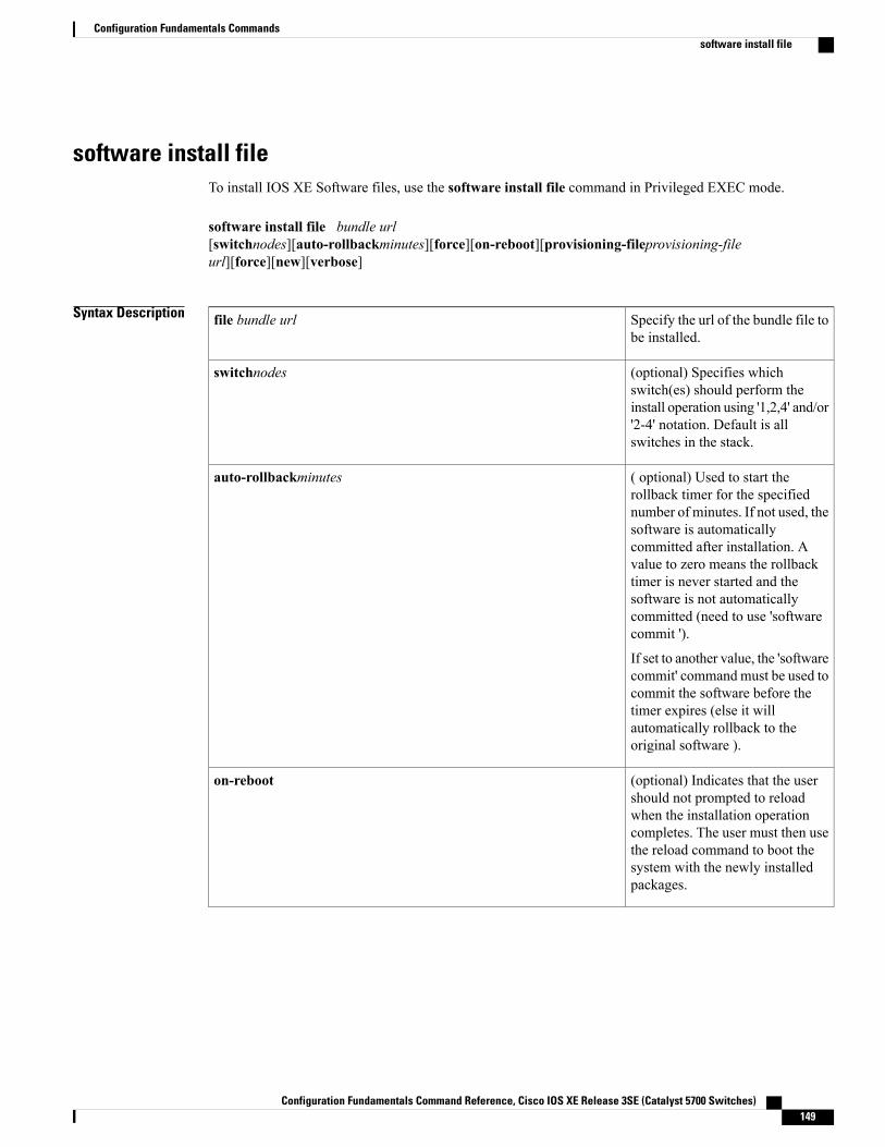
software install fileTo install IOS XE Software files, use the software install file command in Privileged EXEC mode.
software install file bundle url[switchnodes][auto-rollbackminutes][force][on-reboot][provisioning-fileprovisioning-fileurl][force][new][verbose]
Syntax Description Specify the url of the bundle file tobe installed.
file bundle url
(optional) Specifies whichswitch(es) should perform theinstall operation using '1,2,4' and/or'2-4' notation. Default is allswitches in the stack.
switchnodes
( optional) Used to start therollback timer for the specifiednumber of minutes. If not used, thesoftware is automaticallycommitted after installation. Avalue to zero means the rollbacktimer is never started and thesoftware is not automaticallycommitted (need to use 'softwarecommit ').
If set to another value, the 'softwarecommit' command must be used tocommit the software before thetimer expires (else it willautomatically rollback to theoriginal software ).
auto-rollbackminutes
(optional) Indicates that the usershould not prompted to reloadwhen the installation operationcompletes. The user must then usethe reload command to boot thesystem with the newly installedpackages.
on-reboot
Configuration Fundamentals Command Reference, Cisco IOS XE Release 3SE (Catalyst 5700 Switches) 149
Configuration Fundamentals Commandssoftware install file
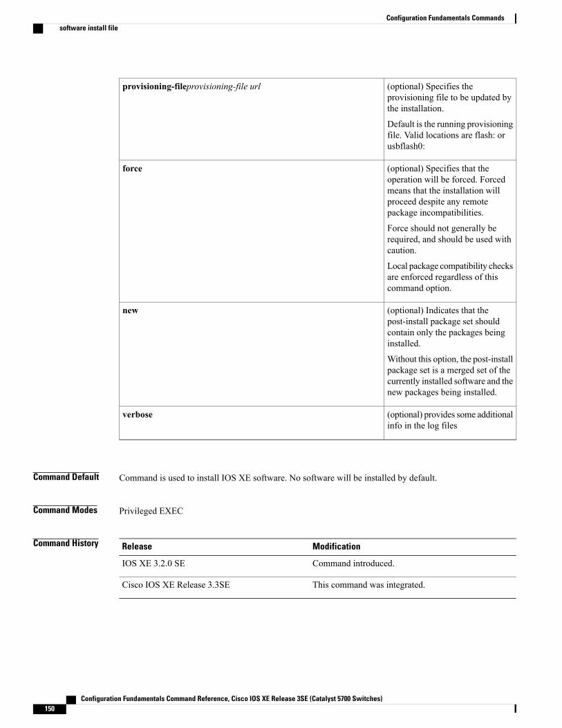
(optional) Specifies theprovisioning file to be updated bythe installation.
Default is the running provisioningfile. Valid locations are flash: orusbflash0:
provisioning-fileprovisioning-file url
(optional) Specifies that theoperation will be forced. Forcedmeans that the installation willproceed despite any remotepackage incompatibilities.
Force should not generally berequired, and should be used withcaution.
Local package compatibility checksare enforced regardless of thiscommand option.
force
(optional) Indicates that thepost-install package set shouldcontain only the packages beinginstalled.
Without this option, the post-installpackage set is a merged set of thecurrently installed software and thenew packages being installed.
new
(optional) provides some additionalinfo in the log files
verbose
Command Default Command is used to install IOS XE software. No software will be installed by default.
Command Modes Privileged EXEC
Command History ModificationRelease
Command introduced.IOS XE 3.2.0 SE
This command was integrated.Cisco IOS XE Release 3.3SE
Configuration Fundamentals Command Reference, Cisco IOS XE Release 3SE (Catalyst 5700 Switches)150
Configuration Fundamentals Commandssoftware install file
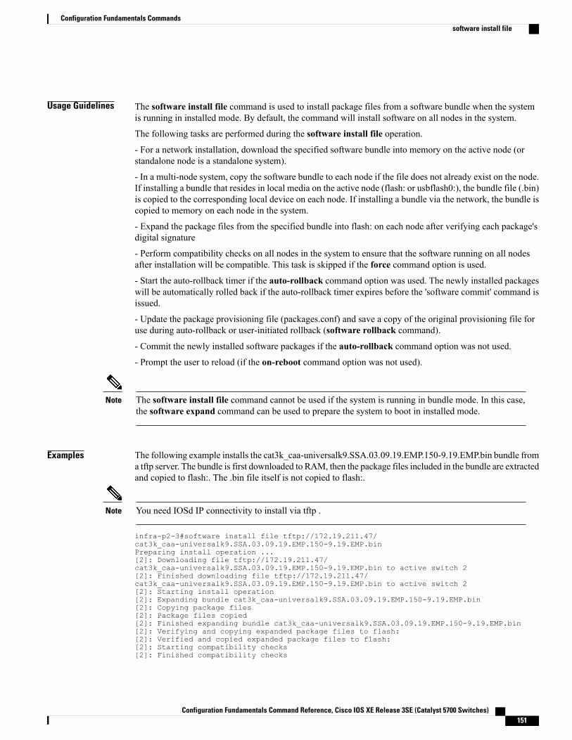
Usage Guidelines The software install file command is used to install package files from a software bundle when the systemis running in installed mode. By default, the command will install software on all nodes in the system.
The following tasks are performed during the software install file operation.
- For a network installation, download the specified software bundle into memory on the active node (orstandalone node is a standalone system).
- In a multi-node system, copy the software bundle to each node if the file does not already exist on the node.If installing a bundle that resides in local media on the active node (flash: or usbflash0:), the bundle file (.bin)is copied to the corresponding local device on each node. If installing a bundle via the network, the bundle iscopied to memory on each node in the system.
- Expand the package files from the specified bundle into flash: on each node after verifying each package'sdigital signature
- Perform compatibility checks on all nodes in the system to ensure that the software running on all nodesafter installation will be compatible. This task is skipped if the force command option is used.
- Start the auto-rollback timer if the auto-rollback command option was used. The newly installed packageswill be automatically rolled back if the auto-rollback timer expires before the 'software commit' command isissued.
- Update the package provisioning file (packages.conf) and save a copy of the original provisioning file foruse during auto-rollback or user-initiated rollback (software rollback command).
- Commit the newly installed software packages if the auto-rollback command option was not used.
- Prompt the user to reload (if the on-reboot command option was not used).
The software install file command cannot be used if the system is running in bundle mode. In this case,the software expand command can be used to prepare the system to boot in installed mode.
Note
Examples The following example installs the cat3k_caa-universalk9.SSA.03.09.19.EMP.150-9.19.EMP.bin bundle froma tftp server. The bundle is first downloaded to RAM, then the package files included in the bundle are extractedand copied to flash:. The .bin file itself is not copied to flash:.
You need IOSd IP connectivity to install via tftp .Note
infra-p2-3#software install file tftp://172.19.211.47/cat3k_caa-universalk9.SSA.03.09.19.EMP.150-9.19.EMP.binPreparing install operation ...[2]: Downloading file tftp://172.19.211.47/cat3k_caa-universalk9.SSA.03.09.19.EMP.150-9.19.EMP.bin to active switch 2[2]: Finished downloading file tftp://172.19.211.47/cat3k_caa-universalk9.SSA.03.09.19.EMP.150-9.19.EMP.bin to active switch 2[2]: Starting install operation[2]: Expanding bundle cat3k_caa-universalk9.SSA.03.09.19.EMP.150-9.19.EMP.bin[2]: Copying package files[2]: Package files copied[2]: Finished expanding bundle cat3k_caa-universalk9.SSA.03.09.19.EMP.150-9.19.EMP.bin[2]: Verifying and copying expanded package files to flash:[2]: Verified and copied expanded package files to flash:[2]: Starting compatibility checks[2]: Finished compatibility checks
Configuration Fundamentals Command Reference, Cisco IOS XE Release 3SE (Catalyst 5700 Switches) 151
Configuration Fundamentals Commandssoftware install file
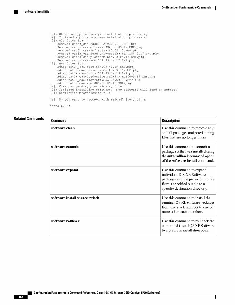
[2]: Starting application pre-installation processing[2]: Finished application pre-installation processing[2]: Old files list:
Removed cat3k_caa-base.SSA.03.09.17.EMP.pkgRemoved cat3k_caa-drivers.SSA.03.09.17.EMP.pkgRemoved cat3k_caa-infra.SSA.03.09.17.EMP.pkgRemoved cat3k_caa-iosd-universalk9.SSA.150-9.17.EMP.pkgRemoved cat3k_caa-platform.SSA.03.09.17.EMP.pkgRemoved cat3k_caa-wcm.SSA.03.09.17.EMP.pkg
[2]: New files list:Added cat3k_caa-base.SSA.03.09.19.EMP.pkgAdded cat3k_caa-drivers.SSA.03.09.19.EMP.pkgAdded cat3k_caa-infra.SSA.03.09.19.EMP.pkgAdded cat3k_caa-iosd-universalk9.SSA.150-9.19.EMP.pkgAdded cat3k_caa-platform.SSA.03.09.19.EMP.pkgAdded cat3k_caa-wcm.SSA.03.09.19.EMP.pkg
[2]: Creating pending provisioning file[2]: Finished installing software. New software will load on reboot.[2]: Committing provisioning file
[2]: Do you want to proceed with reload? [yes/no]: n
infra-p2-3#
Related Commands DescriptionCommand
Use this command to remove anyand all packages and provisioningfiles that are no longer in use.
software clean
Use this command to commit apackage set that was installed usingthe auto-rollback command optionof the software install command.
software commit
Use this command to expandindividual IOS XE Softwarepackages and the provisioning filefrom a specified bundle to aspecific destination directory.
software expand
Use this command to install therunning IOSXE software packagesfrom one stack member to one ormore other stack members.
software install source switch
Use this command to roll back thecommitted Cisco IOSXE Softwareto a previous installation point.
software rollback
Configuration Fundamentals Command Reference, Cisco IOS XE Release 3SE (Catalyst 5700 Switches)152
Configuration Fundamentals Commandssoftware install file
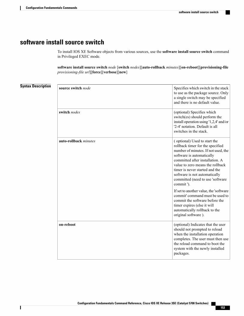
software install source switchTo install IOS XE Software objects from various sources, use the software install source switch commandin Privileged EXEC mode.
software install source switch node [switch nodes][auto-rollback minutes][on-reboot][provisioning-fileprovisioning-file url][force][verbose][new]
Syntax Description Specifies which switch in the stackto use as the package source. Onlya single switch may be specifiedand there is no default value.
source switch node
(optional) Specifies whichswitch(es) should perform theinstall operation using '1,2,4' and/or'2-4' notation. Default is allswitches in the stack.
switch nodes
( optional) Used to start therollback timer for the specifiednumber of minutes. If not used, thesoftware is automaticallycommitted after installation. Avalue to zero means the rollbacktimer is never started and thesoftware is not automaticallycommitted (need to use 'softwarecommit ').
If set to another value, the 'softwarecommit' command must be used tocommit the software before thetimer expires (else it willautomatically rollback to theoriginal software ).
auto-rollback minutes
(optional) Indicates that the usershould not prompted to reloadwhen the installation operationcompletes. The user must then usethe reload command to boot thesystem with the newly installedpackages.
on-reboot
Configuration Fundamentals Command Reference, Cisco IOS XE Release 3SE (Catalyst 5700 Switches) 153
Configuration Fundamentals Commandssoftware install source switch
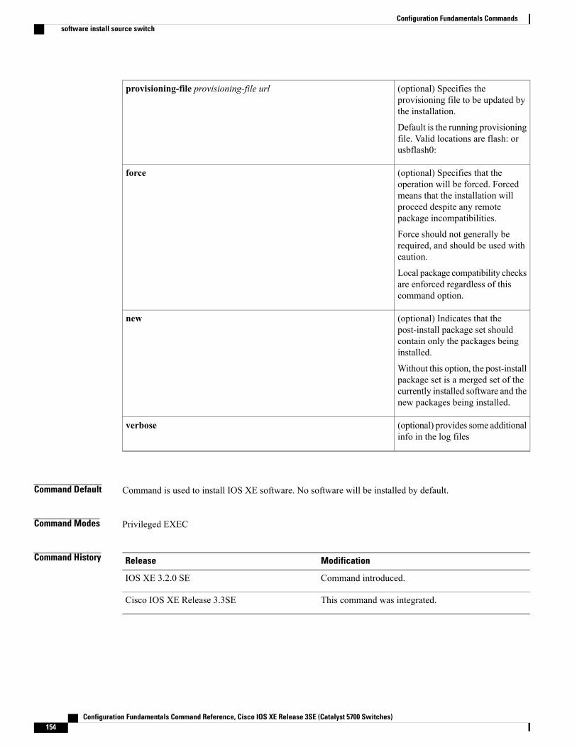
(optional) Specifies theprovisioning file to be updated bythe installation.
Default is the running provisioningfile. Valid locations are flash: orusbflash0:
provisioning-file provisioning-file url
(optional) Specifies that theoperation will be forced. Forcedmeans that the installation willproceed despite any remotepackage incompatibilities.
Force should not generally berequired, and should be used withcaution.
Local package compatibility checksare enforced regardless of thiscommand option.
force
(optional) Indicates that thepost-install package set shouldcontain only the packages beinginstalled.
Without this option, the post-installpackage set is a merged set of thecurrently installed software and thenew packages being installed.
new
(optional) provides some additionalinfo in the log files
verbose
Command Default Command is used to install IOS XE software. No software will be installed by default.
Command Modes Privileged EXEC
Command History ModificationRelease
Command introduced.IOS XE 3.2.0 SE
This command was integrated.Cisco IOS XE Release 3.3SE
Configuration Fundamentals Command Reference, Cisco IOS XE Release 3SE (Catalyst 5700 Switches)154
Configuration Fundamentals Commandssoftware install source switch
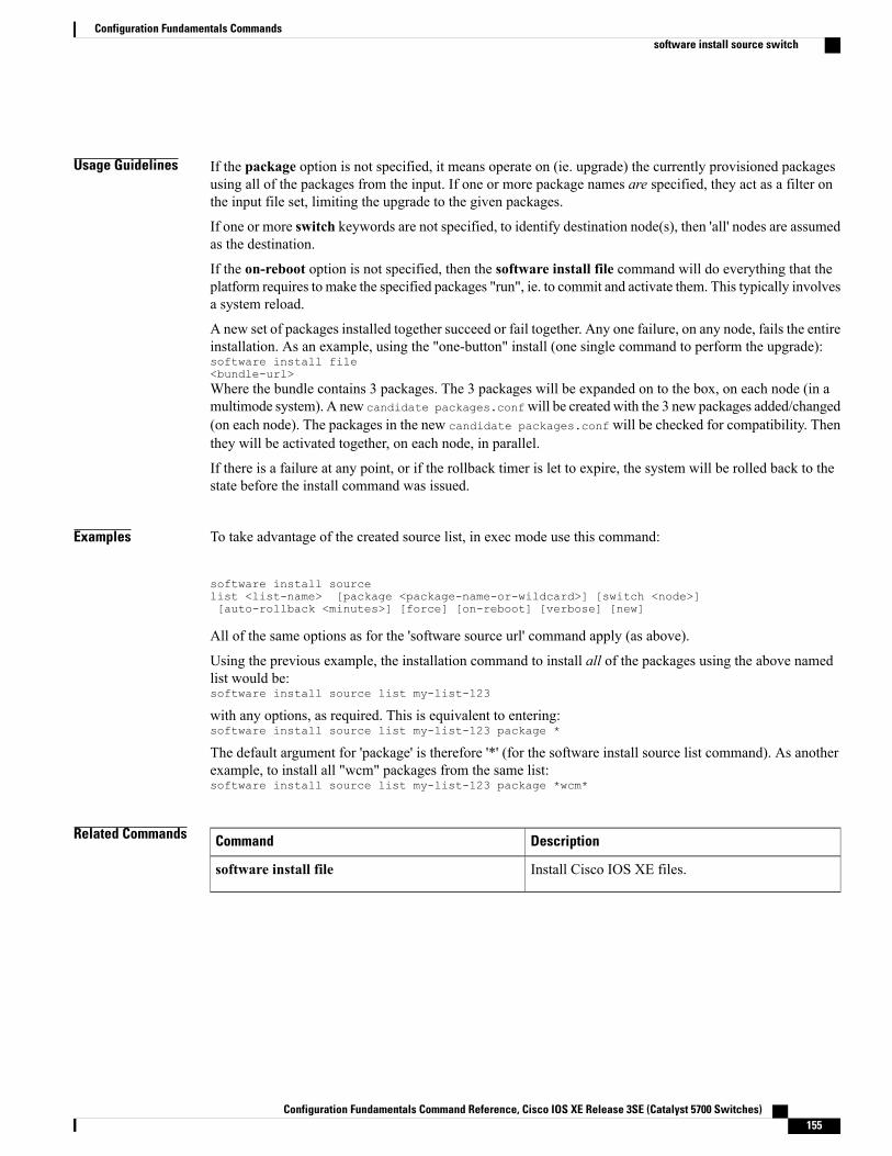
Usage Guidelines If the package option is not specified, it means operate on (ie. upgrade) the currently provisioned packagesusing all of the packages from the input. If one or more package names are specified, they act as a filter onthe input file set, limiting the upgrade to the given packages.
If one or more switch keywords are not specified, to identify destination node(s), then 'all' nodes are assumedas the destination.
If the on-reboot option is not specified, then the software install file command will do everything that theplatform requires to make the specified packages "run", ie. to commit and activate them. This typically involvesa system reload.
A new set of packages installed together succeed or fail together. Any one failure, on any node, fails the entireinstallation. As an example, using the "one-button" install (one single command to perform the upgrade):software install file<bundle-url>Where the bundle contains 3 packages. The 3 packages will be expanded on to the box, on each node (in amultimode system). A new candidate packages.confwill be created with the 3 new packages added/changed(on each node). The packages in the new candidate packages.conf will be checked for compatibility. Thenthey will be activated together, on each node, in parallel.
If there is a failure at any point, or if the rollback timer is let to expire, the system will be rolled back to thestate before the install command was issued.
Examples To take advantage of the created source list, in exec mode use this command:
software install sourcelist <list-name> [package <package-name-or-wildcard>] [switch <node>][auto-rollback <minutes>] [force] [on-reboot] [verbose] [new]
All of the same options as for the 'software source url' command apply (as above).
Using the previous example, the installation command to install all of the packages using the above namedlist would be:software install source list my-list-123
with any options, as required. This is equivalent to entering:software install source list my-list-123 package *
The default argument for 'package' is therefore '*' (for the software install source list command). As anotherexample, to install all "wcm" packages from the same list:software install source list my-list-123 package *wcm*
Related Commands DescriptionCommand
Install Cisco IOS XE files.software install file
Configuration Fundamentals Command Reference, Cisco IOS XE Release 3SE (Catalyst 5700 Switches) 155
Configuration Fundamentals Commandssoftware install source switch
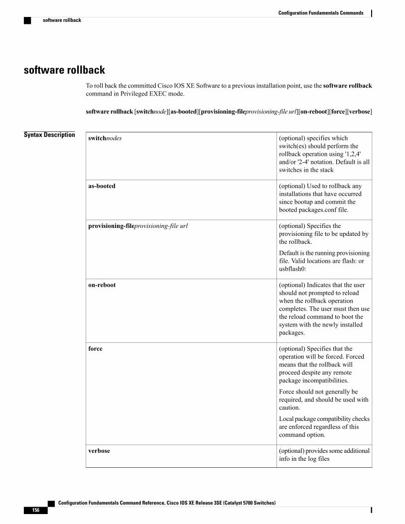
software rollbackTo roll back the committed Cisco IOS XE Software to a previous installation point, use the software rollbackcommand in Privileged EXEC mode.
software rollback [switchnode][as-booted][provisioning-fileprovisioning-file url][on-reboot][force][verbose]
Syntax Description (optional) specifies whichswitch(es) should perform therollback operation using '1,2,4'and/or '2-4' notation. Default is allswitches in the stack
switchnodes
(optional) Used to rollback anyinstallations that have occurredsince bootup and commit thebooted packages.conf file.
as-booted
(optional) Specifies theprovisioning file to be updated bythe rollback.
Default is the running provisioningfile. Valid locations are flash: orusbflash0:
provisioning-fileprovisioning-file url
(optional) Indicates that the usershould not prompted to reloadwhen the rollback operationcompletes. The user must then usethe reload command to boot thesystem with the newly installedpackages.
on-reboot
(optional) Specifies that theoperation will be forced. Forcedmeans that the rollback willproceed despite any remotepackage incompatibilities.
Force should not generally berequired, and should be used withcaution.
Local package compatibility checksare enforced regardless of thiscommand option.
force
(optional) provides some additionalinfo in the log files
verbose
Configuration Fundamentals Command Reference, Cisco IOS XE Release 3SE (Catalyst 5700 Switches)156
Configuration Fundamentals Commandssoftware rollback
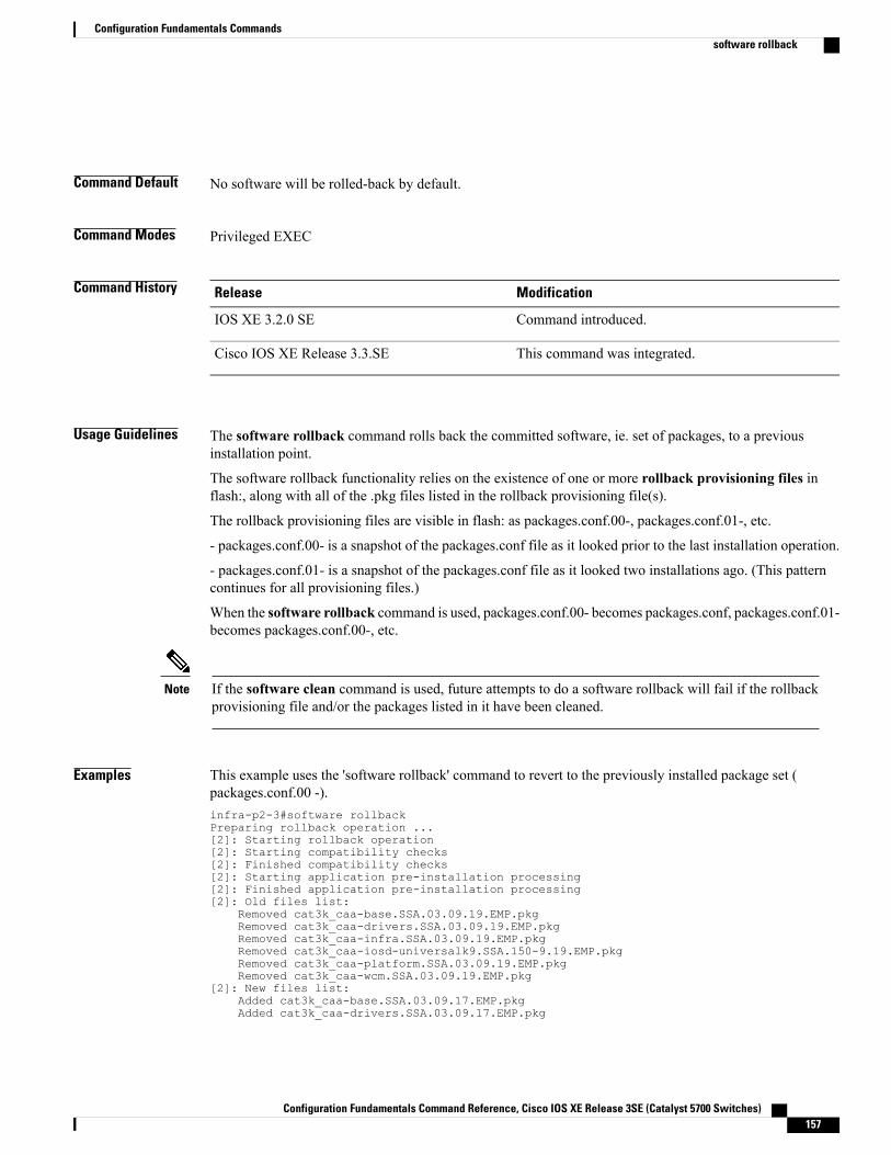
Command Default No software will be rolled-back by default.
Command Modes Privileged EXEC
Command History ModificationRelease
Command introduced.IOS XE 3.2.0 SE
This command was integrated.Cisco IOS XE Release 3.3.SE
Usage Guidelines The software rollback command rolls back the committed software, ie. set of packages, to a previousinstallation point.
The software rollback functionality relies on the existence of one or more rollback provisioning files inflash:, along with all of the .pkg files listed in the rollback provisioning file(s).
The rollback provisioning files are visible in flash: as packages.conf.00-, packages.conf.01-, etc.
- packages.conf.00- is a snapshot of the packages.conf file as it looked prior to the last installation operation.
- packages.conf.01- is a snapshot of the packages.conf file as it looked two installations ago. (This patterncontinues for all provisioning files.)
When the software rollback command is used, packages.conf.00- becomes packages.conf, packages.conf.01-becomes packages.conf.00-, etc.
If the software clean command is used, future attempts to do a software rollback will fail if the rollbackprovisioning file and/or the packages listed in it have been cleaned.
Note
Examples This example uses the 'software rollback' command to revert to the previously installed package set (packages.conf.00 -).infra-p2-3#software rollbackPreparing rollback operation ...[2]: Starting rollback operation[2]: Starting compatibility checks[2]: Finished compatibility checks[2]: Starting application pre-installation processing[2]: Finished application pre-installation processing[2]: Old files list:
Removed cat3k_caa-base.SSA.03.09.19.EMP.pkgRemoved cat3k_caa-drivers.SSA.03.09.19.EMP.pkgRemoved cat3k_caa-infra.SSA.03.09.19.EMP.pkgRemoved cat3k_caa-iosd-universalk9.SSA.150-9.19.EMP.pkgRemoved cat3k_caa-platform.SSA.03.09.19.EMP.pkgRemoved cat3k_caa-wcm.SSA.03.09.19.EMP.pkg
[2]: New files list:Added cat3k_caa-base.SSA.03.09.17.EMP.pkgAdded cat3k_caa-drivers.SSA.03.09.17.EMP.pkg
Configuration Fundamentals Command Reference, Cisco IOS XE Release 3SE (Catalyst 5700 Switches) 157
Configuration Fundamentals Commandssoftware rollback
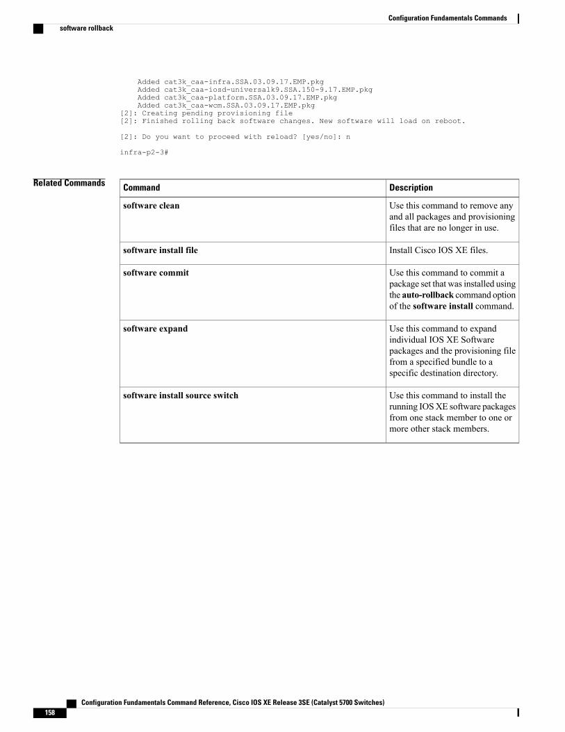
Added cat3k_caa-infra.SSA.03.09.17.EMP.pkgAdded cat3k_caa-iosd-universalk9.SSA.150-9.17.EMP.pkgAdded cat3k_caa-platform.SSA.03.09.17.EMP.pkgAdded cat3k_caa-wcm.SSA.03.09.17.EMP.pkg
[2]: Creating pending provisioning file[2]: Finished rolling back software changes. New software will load on reboot.
[2]: Do you want to proceed with reload? [yes/no]: n
infra-p2-3#
Related Commands DescriptionCommand
Use this command to remove anyand all packages and provisioningfiles that are no longer in use.
software clean
Install Cisco IOS XE files.software install file
Use this command to commit apackage set that was installed usingthe auto-rollback command optionof the software install command.
software commit
Use this command to expandindividual IOS XE Softwarepackages and the provisioning filefrom a specified bundle to aspecific destination directory.
software expand
Use this command to install therunning IOSXE software packagesfrom one stack member to one ormore other stack members.
software install source switch
Configuration Fundamentals Command Reference, Cisco IOS XE Release 3SE (Catalyst 5700 Switches)158
Configuration Fundamentals Commandssoftware rollback
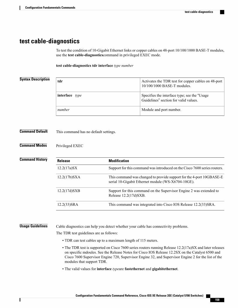
test cable-diagnosticsTo test the condition of 10-Gigabit Ethernet links or copper cables on 48-port 10/100/1000 BASE-T modules,use the test cable-diagnosticscommand in privileged EXEC mode.
test cable-diagnostics tdr interface type number
Syntax Description Activates the TDR test for copper cables on 48-port10/100/1000 BASE-T modules.
tdr
Specifies the interface type; see the “UsageGuidelines” section for valid values.
interface type
Module and port number.number
Command Default This command has no default settings.
Command Modes Privileged EXEC
Command History ModificationRelease
Support for this commandwas introduced on the Cisco 7600 series routers.12.2(17a)SX
This command was changed to provide support for the 4-port 10GBASE-Eserial 10-Gigabit Ethernet module (WS-X6704-10GE).
12.2(17b)SXA
Support for this command on the Supervisor Engine 2 was extended toRelease 12.2(17d)SXB.
12.2(17d)SXB
This command was integrated into Cisco IOS Release 12.2(33)SRA.12.2(33)SRA
Usage Guidelines Cable diagnostics can help you detect whether your cable has connectivity problems.
The TDR test guidelines are as follows:
• TDR can test cables up to a maximum length of 115 meters.
• The TDR test is supported on Cisco 7600 series routers running Release 12.2(17a)SX and later releaseson specific mdoules. See the Release Notes for Cisco IOS Release 12.2SX on the Catalyst 6500 andCisco 7600 Supervisor Engine 720, Supervisor Engine 32, and Supervisor Engine 2 for the list of themodules that support TDR.
• The valid values for interface typeare fastethernet and gigabitethernet.
Configuration Fundamentals Command Reference, Cisco IOS XE Release 3SE (Catalyst 5700 Switches) 159
Configuration Fundamentals Commandstest cable-diagnostics
• Do not start the test at the same time on both ends of the cable. Starting the test at both ends of the cableat the same time can lead to false test results.
• Do not change the port configuration during any cable diagnostics test. This action may result in incorrecttest results.
• The interface must be up before running the TDR test. If the port is down, the test cable-diagnosticstdr command is rejected and the following message is displayed:
Router# test cable-diagnostics tdr interface gigabitethernet2/12% Interface Gi2/12 is administratively down% Use 'no shutdown' to enable interface before TDR test start.
• If the port speed is 1000 and the link is up, do not disable the auto-MDIX feature.
• For fixed 10/100 ports, before running the TDR test, disable auto-MDIX on both sides of the cable.Failure to do so can lead to misleading results.
• For all other conditions, you must disable the auto-MDIX feature on both ends of the cable (use the nomdix autocommand). Failure to disable auto-MDIX will interfere with the TDR test and generate falseresults.
• If a link partner has auto-MDIX enabled, this action will interfere with the TDR-cable diagnostics testand test results will be misleading. The workaround is to disable auto-MDIX on the link partner.
• If you change the port speed from 1000 to 10/100, enter the no mdix autocommand before running theTDR test. Note that entering the speed 1000 command enables auto-MDIX regardless of whether theno mdix autocommand has been run.
Examples This example shows how to run the TDR-cable diagnostics:
Router # test cable-diagnostics tdr interface gigabitethernet2/1TDR test started on interface Gi2/1A TDR test can take a few seconds to run on an interfaceUse 'show cable-diagnostics tdr' to read the TDR results.
Related Commands DescriptionCommand
Clears a specific interface or clears all interfaces thatsupport TDR.
clear cable-diagnostics tdr
Displays the test results for the TDR cablediagnostics.
show cable-diagnostics tdr
Configuration Fundamentals Command Reference, Cisco IOS XE Release 3SE (Catalyst 5700 Switches)160
Configuration Fundamentals Commandstest cable-diagnostics
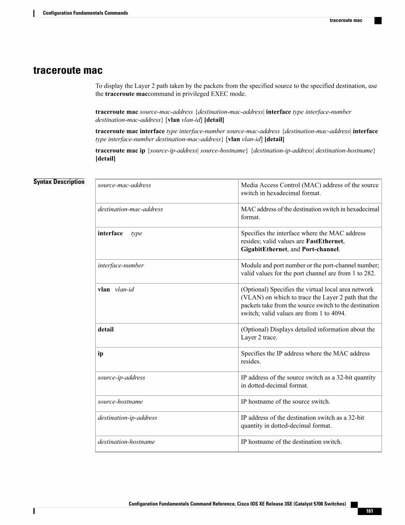
traceroute macTo display the Layer 2 path taken by the packets from the specified source to the specified destination, usethe traceroute maccommand in privileged EXEC mode.
traceroute mac source-mac-address {destination-mac-address| interface type interface-numberdestination-mac-address} [vlan vlan-id] [detail]
traceroute mac interface type interface-number source-mac-address {destination-mac-address| interfacetype interface-number destination-mac-address} [vlan vlan-id] [detail]
traceroute mac ip {source-ip-address| source-hostname} {destination-ip-address| destination-hostname}[detail]
Syntax Description Media Access Control (MAC) address of the sourceswitch in hexadecimal format.
source-mac-address
MACaddress of the destination switch in hexadecimalformat.
destination-mac-address
Specifies the interface where the MAC addressresides; valid values are FastEthernet,GigabitEthernet, and Port-channel.
interface type
Module and port number or the port-channel number;valid values for the port channel are from 1 to 282.
interface-number
(Optional) Specifies the virtual local area network(VLAN) on which to trace the Layer 2 path that thepackets take from the source switch to the destinationswitch; valid values are from 1 to 4094.
vlan vlan-id
(Optional) Displays detailed information about theLayer 2 trace.
detail
Specifies the IP address where the MAC addressresides.
ip
IP address of the source switch as a 32-bit quantityin dotted-decimal format.
source-ip-address
IP hostname of the source switch.source-hostname
IP address of the destination switch as a 32-bitquantity in dotted-decimal format.
destination-ip-address
IP hostname of the destination switch.destination-hostname
Configuration Fundamentals Command Reference, Cisco IOS XE Release 3SE (Catalyst 5700 Switches) 161
Configuration Fundamentals Commandstraceroute mac
Command Default This command has no default settings.
Command Modes Privileged EXEC
Command History ModificationRelease
Support for this command was introduced on the Supervisor Engine720.
12.2(18)SXE
This command was integrated into Cisco IOS Release 12.2(33)SRA.12.2(33)SRA
Usage Guidelines This command is not supported on the Cisco 7600 series router that is configured with a Supervisor Engine2.
Do not use leading zeros when entering a VLAN ID.
For Layer 2 traceroute to functional properly, you must enable CDP on all of the switches in the network. Donot disable CDP.
When the switch detects a device in the Layer 2 path that does not support Layer 2 traceroute, the switchcontinues to send Layer 2 trace queries and lets them time out.
The maximum number of hops identified in the path is ten .
Layer 2 traceroute supports only unicast traffic. If you specify a multicast source or destinationMAC address,the physical path is not identified, and a message appears.
The traceroute mac command output shows the Layer 2 path when the specified source and destinationaddresses belong to the same VLAN. If you specify source and destination addresses that belong to differentVLANs, the Layer 2 path is not identified, and a message appears.
If the source or destination MAC address belongs to multiple VLANs, you must specify the VLAN to whichboth the source and destinationMAC addresses belong. If the VLAN is not specified, the path is not identified,and a message appears.
When multiple devices are attached to one port through hubs (for example, multiple CDP neighbors aredetected on a port), the Layer 2 traceroute utility terminates at that hop and displays an error message.
This feature is not supported in Token Ring VLANs.
Examples This example shows how to display detailed information about the Layer 2 path:
Router# traceroute mac 0001.0000.0204 0001.0000.0304 detailSource 1001.0000.0204 found on VAYU[WS-C6509] (10.1.1.10)1 VAYU / WS-C6509 / 10.1.1.10 :Gi6/1 [full, 1000M] => Po100 [auto, auto]2 PANI / WS-C6509 / 10.1.1.12 :Po100 [auto, auto] => Po110 [auto, auto]3 BUMI / WS-C6509 / 10.1.1.13 :Po110 [auto, auto] => Po120 [auto, auto]4 AGNI / WS-C6509 / 10.1.1.11 :Po120 [auto, auto] => Gi8/12 [full, 1000M]
Configuration Fundamentals Command Reference, Cisco IOS XE Release 3SE (Catalyst 5700 Switches)162
Configuration Fundamentals Commandstraceroute mac
Destination 1001.0000.0304 found on AGNI[WS-C6509] (10.1.1.11)Layer 2 trace completed.Router#This example shows the output when the switch is not connected to the source switch:
Router# traceroute mac 0000.0201.0501 0000.0201.0201 detailSource not directly connected, tracing source .....Source 1000.0201.0501 found on con5[WS-C6509] (10.2.5.5)con5 / WS-C6509 / 10.2.5.5 :
Fa0/1 [auto, auto] =>Gi0/1 [auto, auto]con1 / WS-C6509 / 10.2.1.1 :
Gi0/1 [auto, auto] =>Gi0/2 [auto, auto]con2 / WS-C6509 / 10.2.2.2 :
Gi0/2 [auto, auto] =>Fa0/1 [auto, auto]Destination 1000.0201.0201 found on con2[WS-C6509] (10.2.2.2)Layer 2 trace completed.Router#This example shows the output when the switch cannot find the destination port for the source MAC address:
Router# traceroute mac 0000.0011.1111 0000.0201.0201Error:Source Mac address not found.Layer2 trace aborted.Router#This example shows the output when the source and destination devices are in different VLANs:
Router# traceroute mac 0000.0201.0601 0000.0301.0201Error:Source and destination macs are on different vlans.Layer2 trace aborted.Router#This example shows the output when the destination MAC address is a multicast address:
Router# traceroute mac 0000.0201.0601 0100.0201.0201Invalid destination mac addressRouter#This example shows the output when the source and destination switches belong to multiple VLANs:
Router# traceroute mac 0000.0201.0601 0000.0201.0201Error:Mac found on multiple vlans.Layer2 trace aborted.Router#This example shows how to display the Layer 2 path by specifying the interfaces on the source and destinationswitches:
Router# traceroute mac interface fastethernet0/1 0000.0201.0601 interface fastethernet0/30000.0201.0201Source 1000.0201.0601 found on con6[WS-C6509] (10.2.6.6)con6 (10.2.6.6) :Fa0/1 =>Fa0/3con5 (10.2.5.5 ) : Fa0/3 =>Gi0/1con1 (10.2.1.1 ) : Gi0/1 =>Gi0/2con2 (10.2.2.2 ) : Gi0/2 =>Fa0/1Destination 1000.0201.0201 found on con2[WS-C6509] (10.2.2.2)Layer 2 trace completedRouter#This example shows how to display detailed traceroute information:
Router# traceroute mac ip 10.2.66.66 10.2.22.22 detailTranslating IP to mac.....10.2.66.66 =>0000.0201.060110.2.22.22 =>0000.0201.0201Source 0000.0201.0601 found on con6[WS-C6509] (10.2.6.6)con6 / WS-C6509 / 10.2.6.6 :
Fa0/1 [auto, auto] =>Fa0/3 [auto, auto]con5 / WS-C6509 / 10.2.5.5 :
Fa0/3 [auto, auto] =>Gi0/1 [auto, auto]con1 / WS-C6509 / 10.2.1.1 :
Configuration Fundamentals Command Reference, Cisco IOS XE Release 3SE (Catalyst 5700 Switches) 163
Configuration Fundamentals Commandstraceroute mac
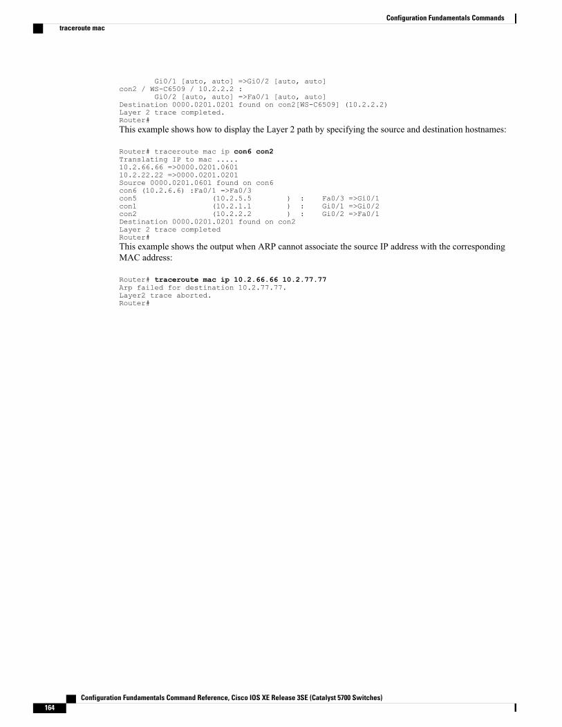
Gi0/1 [auto, auto] =>Gi0/2 [auto, auto]con2 / WS-C6509 / 10.2.2.2 :
Gi0/2 [auto, auto] =>Fa0/1 [auto, auto]Destination 0000.0201.0201 found on con2[WS-C6509] (10.2.2.2)Layer 2 trace completed.Router#This example shows how to display the Layer 2 path by specifying the source and destination hostnames:
Router# traceroute mac ip con6 con2Translating IP to mac .....10.2.66.66 =>0000.0201.060110.2.22.22 =>0000.0201.0201Source 0000.0201.0601 found on con6con6 (10.2.6.6) :Fa0/1 =>Fa0/3con5 (10.2.5.5 ) : Fa0/3 =>Gi0/1con1 (10.2.1.1 ) : Gi0/1 =>Gi0/2con2 (10.2.2.2 ) : Gi0/2 =>Fa0/1Destination 0000.0201.0201 found on con2Layer 2 trace completedRouter#This example shows the output when ARP cannot associate the source IP address with the correspondingMAC address:
Router# traceroute mac ip 10.2.66.66 10.2.77.77Arp failed for destination 10.2.77.77.Layer2 trace aborted.Router#
Configuration Fundamentals Command Reference, Cisco IOS XE Release 3SE (Catalyst 5700 Switches)164
Configuration Fundamentals Commandstraceroute mac
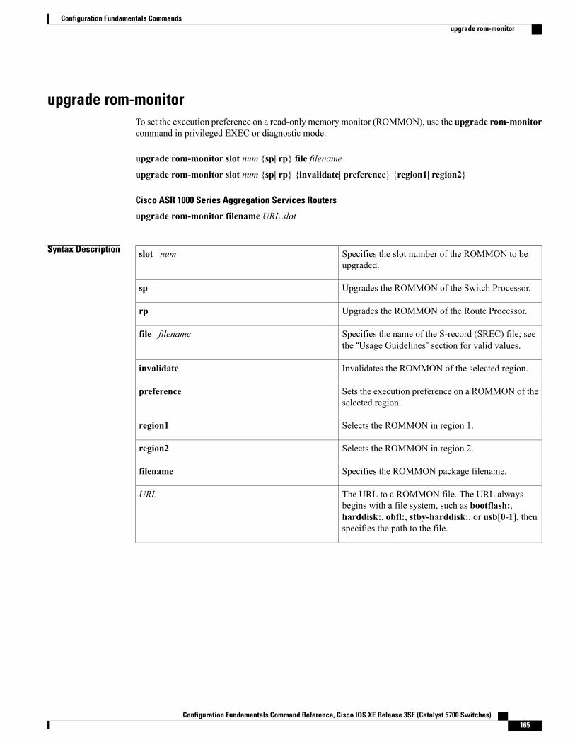
upgrade rom-monitorTo set the execution preference on a read-only memory monitor (ROMMON), use the upgrade rom-monitorcommand in privileged EXEC or diagnostic mode.
upgrade rom-monitor slot num {sp| rp} file filename
upgrade rom-monitor slot num {sp| rp} {invalidate| preference} {region1| region2}
Cisco ASR 1000 Series Aggregation Services Routers
upgrade rom-monitor filename URL slot
Syntax Description Specifies the slot number of the ROMMON to beupgraded.
slot num
Upgrades the ROMMON of the Switch Processor.sp
Upgrades the ROMMON of the Route Processor.rp
Specifies the name of the S-record (SREC) file; seethe “Usage Guidelines” section for valid values.
file filename
Invalidates the ROMMON of the selected region.invalidate
Sets the execution preference on a ROMMON of theselected region.
preference
Selects the ROMMON in region 1.region1
Selects the ROMMON in region 2.region2
Specifies the ROMMON package filename.filename
The URL to a ROMMON file. The URL alwaysbegins with a file system, such as bootflash:,harddisk:, obfl:, stby-harddisk:, or usb[0-1], thenspecifies the path to the file.
URL
Configuration Fundamentals Command Reference, Cisco IOS XE Release 3SE (Catalyst 5700 Switches) 165
Configuration Fundamentals Commandsupgrade rom-monitor
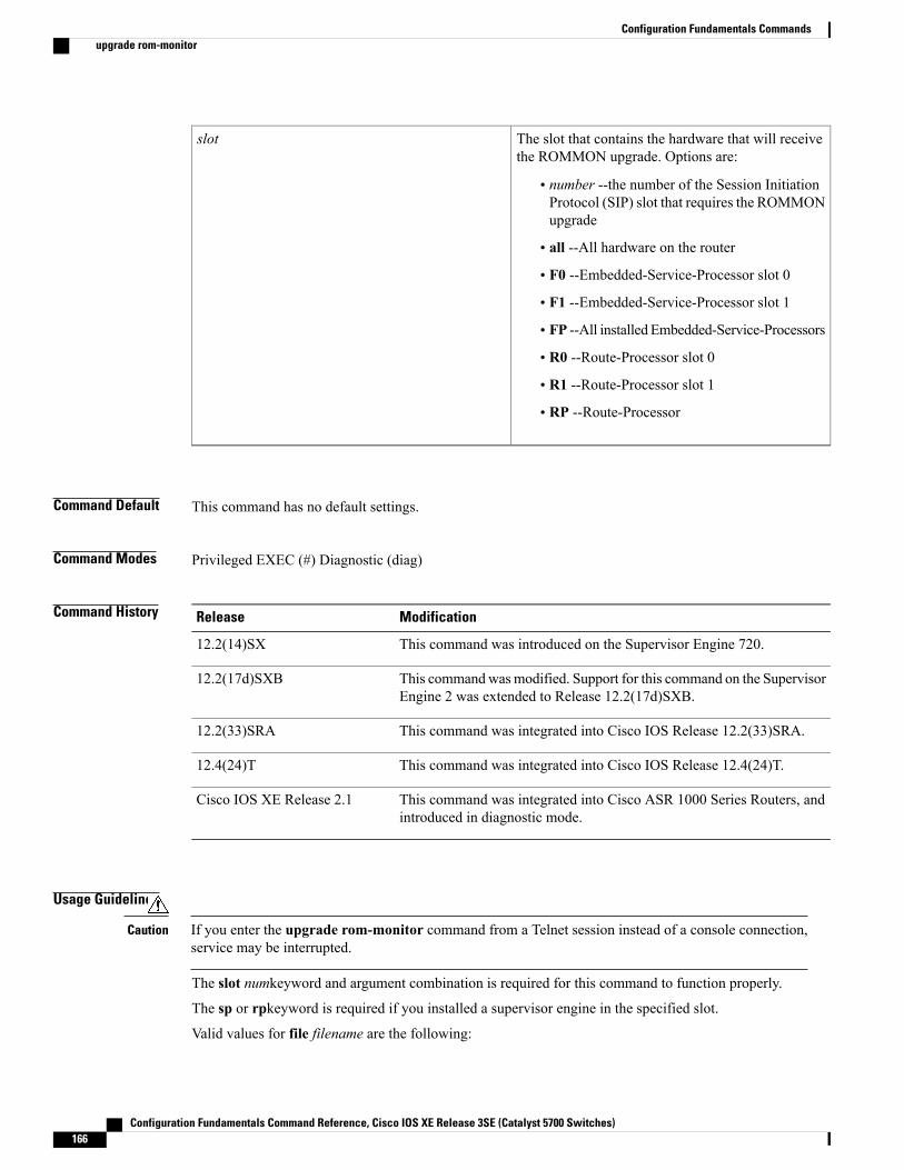
The slot that contains the hardware that will receivethe ROMMON upgrade. Options are:
• number --the number of the Session InitiationProtocol (SIP) slot that requires the ROMMONupgrade
• all --All hardware on the router
• F0 --Embedded-Service-Processor slot 0
• F1 --Embedded-Service-Processor slot 1
• FP --All installed Embedded-Service-Processors
• R0 --Route-Processor slot 0
• R1 --Route-Processor slot 1
• RP --Route-Processor
slot
Command Default This command has no default settings.
Command Modes Privileged EXEC (#) Diagnostic (diag)
Command History ModificationRelease
This command was introduced on the Supervisor Engine 720.12.2(14)SX
This commandwasmodified. Support for this command on the SupervisorEngine 2 was extended to Release 12.2(17d)SXB.
12.2(17d)SXB
This command was integrated into Cisco IOS Release 12.2(33)SRA.12.2(33)SRA
This command was integrated into Cisco IOS Release 12.4(24)T.12.4(24)T
This command was integrated into Cisco ASR 1000 Series Routers, andintroduced in diagnostic mode.
Cisco IOS XE Release 2.1
Usage Guidelines
If you enter the upgrade rom-monitor command from a Telnet session instead of a console connection,service may be interrupted.
Caution
The slot numkeyword and argument combination is required for this command to function properly.
The sp or rpkeyword is required if you installed a supervisor engine in the specified slot.
Valid values for file filename are the following:
Configuration Fundamentals Command Reference, Cisco IOS XE Release 3SE (Catalyst 5700 Switches)166
Configuration Fundamentals Commandsupgrade rom-monitor
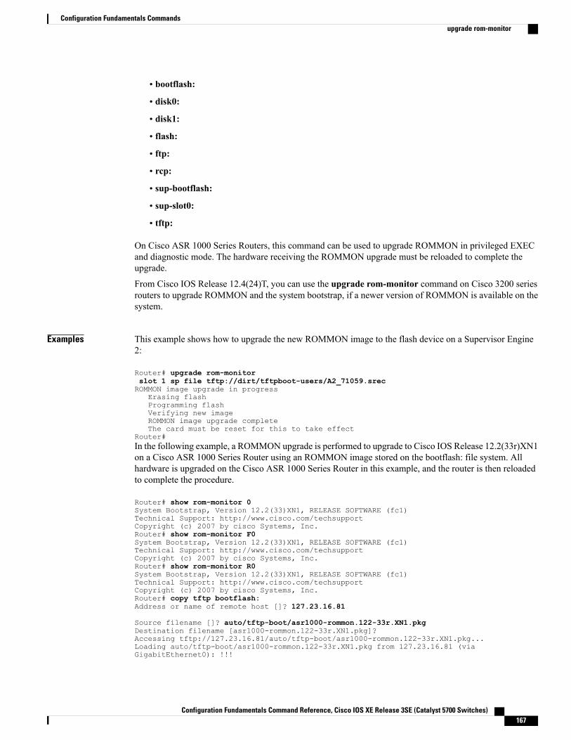
• bootflash:
• disk0:
• disk1:
• flash:
• ftp:
• rcp:
• sup-bootflash:
• sup-slot0:
• tftp:
On Cisco ASR 1000 Series Routers, this command can be used to upgrade ROMMON in privileged EXECand diagnostic mode. The hardware receiving the ROMMON upgrade must be reloaded to complete theupgrade.
From Cisco IOS Release 12.4(24)T, you can use the upgrade rom-monitor command on Cisco 3200 seriesrouters to upgrade ROMMON and the system bootstrap, if a newer version of ROMMON is available on thesystem.
Examples This example shows how to upgrade the new ROMMON image to the flash device on a Supervisor Engine2:
Router# upgrade rom-monitorslot 1 sp file tftp://dirt/tftpboot-users/A2_71059.srecROMMON image upgrade in progress
Erasing flashProgramming flashVerifying new imageROMMON image upgrade completeThe card must be reset for this to take effect
Router#In the following example, a ROMMON upgrade is performed to upgrade to Cisco IOS Release 12.2(33r)XN1on a Cisco ASR 1000 Series Router using an ROMMON image stored on the bootflash: file system. Allhardware is upgraded on the Cisco ASR 1000 Series Router in this example, and the router is then reloadedto complete the procedure.
Router# show rom-monitor 0System Bootstrap, Version 12.2(33)XN1, RELEASE SOFTWARE (fc1)Technical Support: http://www.cisco.com/techsupportCopyright (c) 2007 by cisco Systems, Inc.Router# show rom-monitor F0System Bootstrap, Version 12.2(33)XN1, RELEASE SOFTWARE (fc1)Technical Support: http://www.cisco.com/techsupportCopyright (c) 2007 by cisco Systems, Inc.Router# show rom-monitor R0System Bootstrap, Version 12.2(33)XN1, RELEASE SOFTWARE (fc1)Technical Support: http://www.cisco.com/techsupportCopyright (c) 2007 by cisco Systems, Inc.Router# copy tftp bootflash:Address or name of remote host []? 127.23.16.81
Source filename []? auto/tftp-boot/asr1000-rommon.122-33r.XN1.pkgDestination filename [asr1000-rommon.122-33r.XN1.pkg]?Accessing tftp://127.23.16.81/auto/tftp-boot/asr1000-rommon.122-33r.XN1.pkg...Loading auto/tftp-boot/asr1000-rommon.122-33r.XN1.pkg from 127.23.16.81 (viaGigabitEthernet0): !!!
Configuration Fundamentals Command Reference, Cisco IOS XE Release 3SE (Catalyst 5700 Switches) 167
Configuration Fundamentals Commandsupgrade rom-monitor
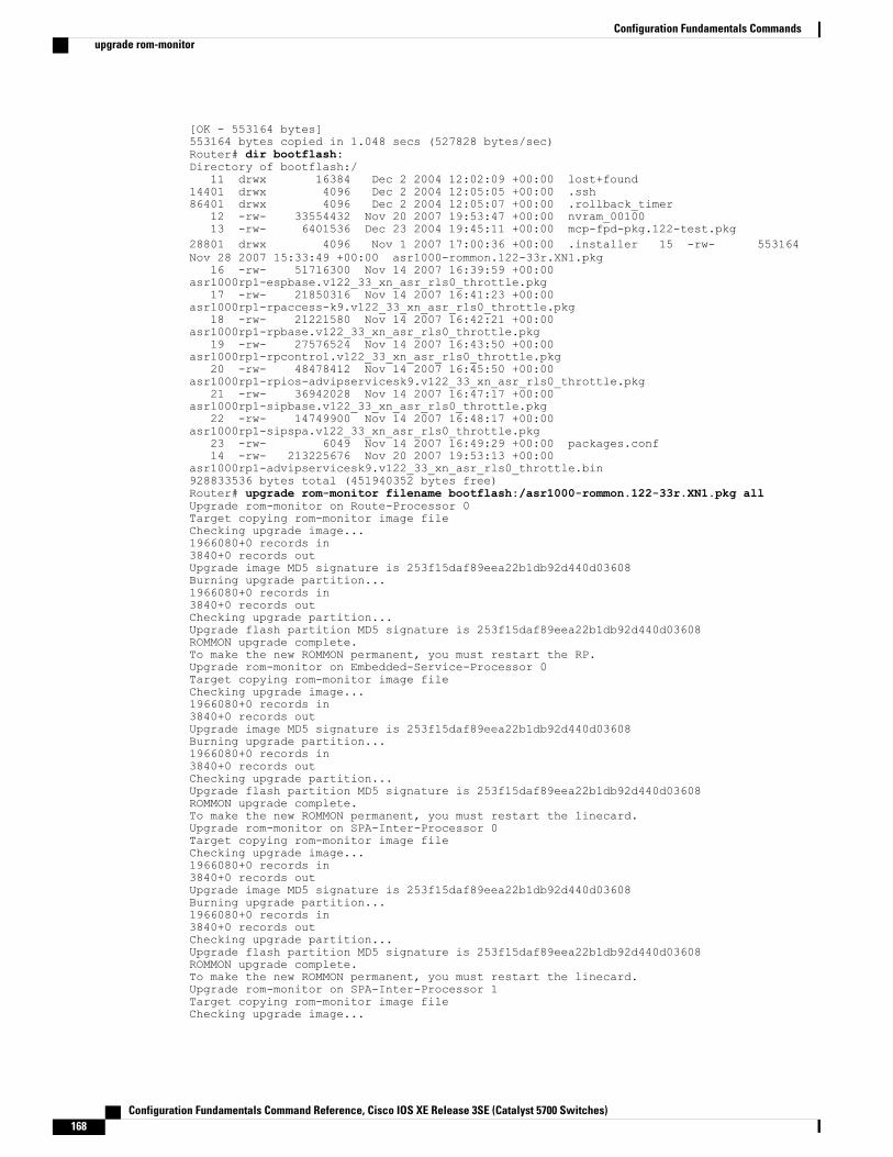
[OK - 553164 bytes]553164 bytes copied in 1.048 secs (527828 bytes/sec)Router# dir bootflash:Directory of bootflash:/
11 drwx 16384 Dec 2 2004 12:02:09 +00:00 lost+found14401 drwx 4096 Dec 2 2004 12:05:05 +00:00 .ssh86401 drwx 4096 Dec 2 2004 12:05:07 +00:00 .rollback_timer
12 -rw- 33554432 Nov 20 2007 19:53:47 +00:00 nvram_0010013 -rw- 6401536 Dec 23 2004 19:45:11 +00:00 mcp-fpd-pkg.122-test.pkg
28801 drwx 4096 Nov 1 2007 17:00:36 +00:00 .installer 15 -rw- 553164Nov 28 2007 15:33:49 +00:00 asr1000-rommon.122-33r.XN1.pkg
16 -rw- 51716300 Nov 14 2007 16:39:59 +00:00asr1000rp1-espbase.v122_33_xn_asr_rls0_throttle.pkg
17 -rw- 21850316 Nov 14 2007 16:41:23 +00:00asr1000rp1-rpaccess-k9.v122_33_xn_asr_rls0_throttle.pkg
18 -rw- 21221580 Nov 14 2007 16:42:21 +00:00asr1000rp1-rpbase.v122_33_xn_asr_rls0_throttle.pkg
19 -rw- 27576524 Nov 14 2007 16:43:50 +00:00asr1000rp1-rpcontrol.v122_33_xn_asr_rls0_throttle.pkg
20 -rw- 48478412 Nov 14 2007 16:45:50 +00:00asr1000rp1-rpios-advipservicesk9.v122_33_xn_asr_rls0_throttle.pkg
21 -rw- 36942028 Nov 14 2007 16:47:17 +00:00asr1000rp1-sipbase.v122_33_xn_asr_rls0_throttle.pkg
22 -rw- 14749900 Nov 14 2007 16:48:17 +00:00asr1000rp1-sipspa.v122_33_xn_asr_rls0_throttle.pkg
23 -rw- 6049 Nov 14 2007 16:49:29 +00:00 packages.conf14 -rw- 213225676 Nov 20 2007 19:53:13 +00:00
asr1000rp1-advipservicesk9.v122_33_xn_asr_rls0_throttle.bin928833536 bytes total (451940352 bytes free)Router# upgrade rom-monitor filename bootflash:/asr1000-rommon.122-33r.XN1.pkg allUpgrade rom-monitor on Route-Processor 0Target copying rom-monitor image fileChecking upgrade image...1966080+0 records in3840+0 records outUpgrade image MD5 signature is 253f15daf89eea22b1db92d440d03608Burning upgrade partition...1966080+0 records in3840+0 records outChecking upgrade partition...Upgrade flash partition MD5 signature is 253f15daf89eea22b1db92d440d03608ROMMON upgrade complete.To make the new ROMMON permanent, you must restart the RP.Upgrade rom-monitor on Embedded-Service-Processor 0Target copying rom-monitor image fileChecking upgrade image...1966080+0 records in3840+0 records outUpgrade image MD5 signature is 253f15daf89eea22b1db92d440d03608Burning upgrade partition...1966080+0 records in3840+0 records outChecking upgrade partition...Upgrade flash partition MD5 signature is 253f15daf89eea22b1db92d440d03608ROMMON upgrade complete.To make the new ROMMON permanent, you must restart the linecard.Upgrade rom-monitor on SPA-Inter-Processor 0Target copying rom-monitor image fileChecking upgrade image...1966080+0 records in3840+0 records outUpgrade image MD5 signature is 253f15daf89eea22b1db92d440d03608Burning upgrade partition...1966080+0 records in3840+0 records outChecking upgrade partition...Upgrade flash partition MD5 signature is 253f15daf89eea22b1db92d440d03608ROMMON upgrade complete.To make the new ROMMON permanent, you must restart the linecard.Upgrade rom-monitor on SPA-Inter-Processor 1Target copying rom-monitor image fileChecking upgrade image...
Configuration Fundamentals Command Reference, Cisco IOS XE Release 3SE (Catalyst 5700 Switches)168
Configuration Fundamentals Commandsupgrade rom-monitor
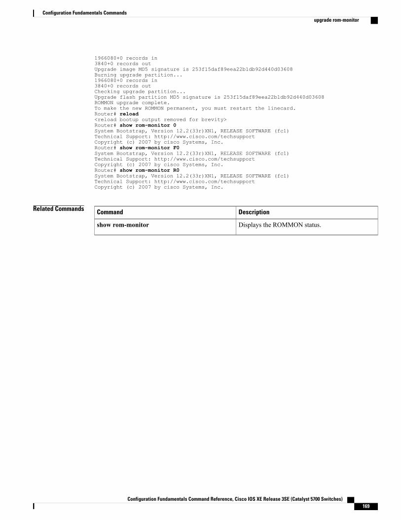
1966080+0 records in3840+0 records outUpgrade image MD5 signature is 253f15daf89eea22b1db92d440d03608Burning upgrade partition...1966080+0 records in3840+0 records outChecking upgrade partition...Upgrade flash partition MD5 signature is 253f15daf89eea22b1db92d440d03608ROMMON upgrade complete.To make the new ROMMON permanent, you must restart the linecard.Router# reload<reload bootup output removed for brevity>Router# show rom-monitor 0System Bootstrap, Version 12.2(33r)XN1, RELEASE SOFTWARE (fc1)Technical Support: http://www.cisco.com/techsupportCopyright (c) 2007 by cisco Systems, Inc.Router# show rom-monitor F0System Bootstrap, Version 12.2(33r)XN1, RELEASE SOFTWARE (fc1)Technical Support: http://www.cisco.com/techsupportCopyright (c) 2007 by cisco Systems, Inc.Router# show rom-monitor R0System Bootstrap, Version 12.2(33r)XN1, RELEASE SOFTWARE (fc1)Technical Support: http://www.cisco.com/techsupportCopyright (c) 2007 by cisco Systems, Inc.
Related Commands DescriptionCommand
Displays the ROMMON status.show rom-monitor
Configuration Fundamentals Command Reference, Cisco IOS XE Release 3SE (Catalyst 5700 Switches) 169
Configuration Fundamentals Commandsupgrade rom-monitor

verifyTo verify the checksum of a file on a flash memory file system or compute aMessage Digest 5 (MD5) signaturefor a file, use the verify command in privileged EXEC mode.
verify [/md5 [ md5-value ]] filesystem: [ file-url ]
Cisco 7600 Series Router
verify {/md5 flash-filesystem [ expected-md5-signature ]| /ios flash-filesystem| flash-filesystem}
Syntax Description (Optional) Calculates and displays theMD5 value forthe specified software image. Compare this value withthe value available on Cisco.com for this image.
/md5
(Optional) The known MD5 value for the specifiedimage. When an MD5 value is specified in thecommand, the system calculates the MD5 value forthe specified image and display a message verifyingthat theMD5 valuesmatch or that there is a mismatch.
md5-value
File system or directory containing the files to list,followed by a colon. Standard file system keywordsfor this command are flash: and bootflash:.
filesystem :
(Optional) The name of the files to display on aspecified device. The files can be of any type. Youcan use wildcards in the filename. A wildcardcharacter (*) matches all patterns. Strings after awildcard are ignored.
file-url
Cisco 7600 Series Router
Computes an MD5 signature for a file; valid valuesare bootflash:, disk0:, disk1:, flash:, orsup-bootflash:.
/md5 flash-filesystem
(Optional) MD5 signature.expected-md5-signature
Verifies the compressed Cisco IOS image checksum;valid values are bootflash:, disk0:, disk1:, flash:, orsup-bootflash:.
/ios flash-filesystem
Device where the Flashmemory resides; valid valuesare bootflash:, disk0:, disk1:, flash:, orsup-bootflash:.
flash-filesystem
Configuration Fundamentals Command Reference, Cisco IOS XE Release 3SE (Catalyst 5700 Switches)170
Configuration Fundamentals Commandsverify
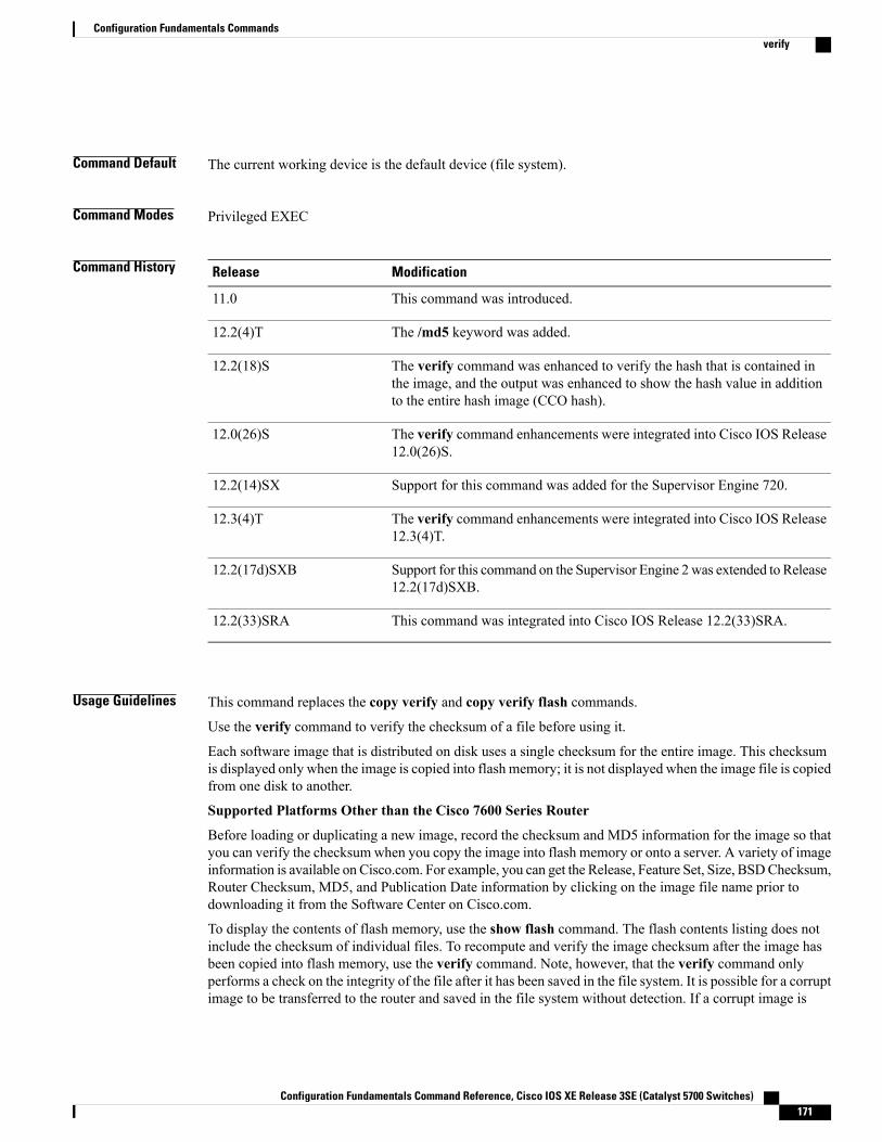
Command Default The current working device is the default device (file system).
Command Modes Privileged EXEC
Command History ModificationRelease
This command was introduced.11.0
The /md5 keyword was added.12.2(4)T
The verify command was enhanced to verify the hash that is contained inthe image, and the output was enhanced to show the hash value in additionto the entire hash image (CCO hash).
12.2(18)S
The verify command enhancements were integrated into Cisco IOS Release12.0(26)S.
12.0(26)S
Support for this command was added for the Supervisor Engine 720.12.2(14)SX
The verify command enhancements were integrated into Cisco IOS Release12.3(4)T.
12.3(4)T
Support for this command on the Supervisor Engine 2was extended to Release12.2(17d)SXB.
12.2(17d)SXB
This command was integrated into Cisco IOS Release 12.2(33)SRA.12.2(33)SRA
Usage Guidelines This command replaces the copy verify and copy verify flash commands.
Use the verify command to verify the checksum of a file before using it.
Each software image that is distributed on disk uses a single checksum for the entire image. This checksumis displayed only when the image is copied into flash memory; it is not displayed when the image file is copiedfrom one disk to another.
Supported Platforms Other than the Cisco 7600 Series Router
Before loading or duplicating a new image, record the checksum and MD5 information for the image so thatyou can verify the checksum when you copy the image into flash memory or onto a server. A variety of imageinformation is available on Cisco.com. For example, you can get the Release, Feature Set, Size, BSDChecksum,Router Checksum, MD5, and Publication Date information by clicking on the image file name prior todownloading it from the Software Center on Cisco.com.
To display the contents of flash memory, use the show flash command. The flash contents listing does notinclude the checksum of individual files. To recompute and verify the image checksum after the image hasbeen copied into flash memory, use the verify command. Note, however, that the verify command onlyperforms a check on the integrity of the file after it has been saved in the file system. It is possible for a corruptimage to be transferred to the router and saved in the file system without detection. If a corrupt image is
Configuration Fundamentals Command Reference, Cisco IOS XE Release 3SE (Catalyst 5700 Switches) 171
Configuration Fundamentals Commandsverify
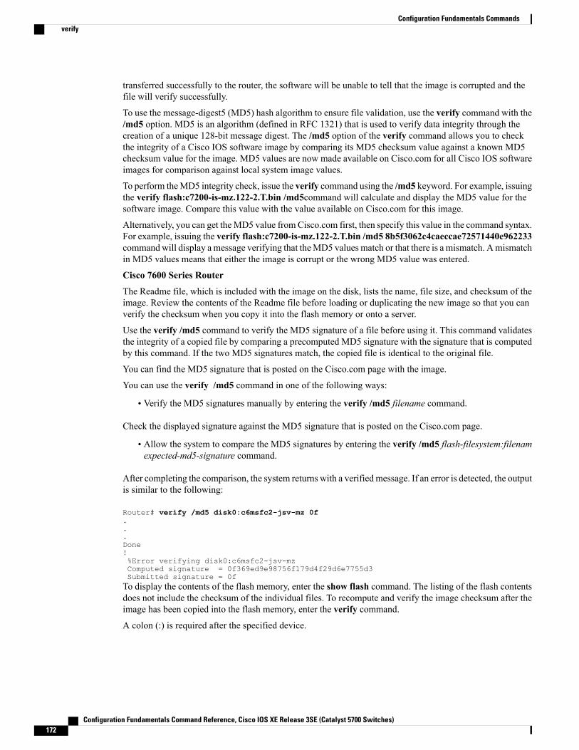
transferred successfully to the router, the software will be unable to tell that the image is corrupted and thefile will verify successfully.
To use the message-digest5 (MD5) hash algorithm to ensure file validation, use the verify command with the/md5 option. MD5 is an algorithm (defined in RFC 1321) that is used to verify data integrity through thecreation of a unique 128-bit message digest. The /md5 option of the verify command allows you to checkthe integrity of a Cisco IOS software image by comparing its MD5 checksum value against a known MD5checksum value for the image. MD5 values are now made available on Cisco.com for all Cisco IOS softwareimages for comparison against local system image values.
To perform theMD5 integrity check, issue the verify command using the /md5 keyword. For example, issuingthe verify flash:c7200-is-mz.122-2.T.bin /md5command will calculate and display the MD5 value for thesoftware image. Compare this value with the value available on Cisco.com for this image.
Alternatively, you can get theMD5 value from Cisco.com first, then specify this value in the command syntax.For example, issuing the verify flash:c7200-is-mz.122-2.T.bin /md5 8b5f3062c4caeccae72571440e962233commandwill display a message verifying that theMD5 values match or that there is a mismatch. Amismatchin MD5 values means that either the image is corrupt or the wrong MD5 value was entered.
Cisco 7600 Series Router
The Readme file, which is included with the image on the disk, lists the name, file size, and checksum of theimage. Review the contents of the Readme file before loading or duplicating the new image so that you canverify the checksum when you copy it into the flash memory or onto a server.
Use the verify /md5 command to verify the MD5 signature of a file before using it. This command validatesthe integrity of a copied file by comparing a precomputed MD5 signature with the signature that is computedby this command. If the two MD5 signatures match, the copied file is identical to the original file.
You can find the MD5 signature that is posted on the Cisco.com page with the image.
You can use the verify /md5 command in one of the following ways:
• Verify the MD5 signatures manually by entering the verify /md5 filename command.
Check the displayed signature against the MD5 signature that is posted on the Cisco.com page.
• Allow the system to compare the MD5 signatures by entering the verify /md5 flash-filesystem:filenamexpected-md5-signature command.
After completing the comparison, the system returns with a verified message. If an error is detected, the outputis similar to the following:
Router# verify /md5 disk0:c6msfc2-jsv-mz 0f...Done!%Error verifying disk0:c6msfc2-jsv-mzComputed signature = 0f369ed9e98756f179d4f29d6e7755d3Submitted signature = 0fTo display the contents of the flash memory, enter the show flash command. The listing of the flash contentsdoes not include the checksum of the individual files. To recompute and verify the image checksum after theimage has been copied into the flash memory, enter the verify command.
A colon (:) is required after the specified device.
Configuration Fundamentals Command Reference, Cisco IOS XE Release 3SE (Catalyst 5700 Switches)172
Configuration Fundamentals Commandsverify
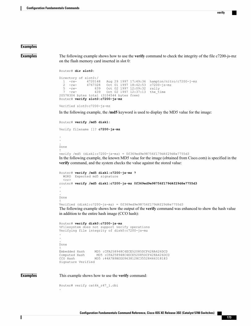
Examples
Examples The following example shows how to use the verify command to check the integrity of the file c7200-js-mzon the flash memory card inserted in slot 0:
Router# dir slot0:
Directory of slot0:/1 -rw- 4720148 Aug 29 1997 17:49:36 hampton/nitro/c7200-j-mz2 -rw- 4767328 Oct 01 1997 18:42:53 c7200-js-mz5 -rw- 639 Oct 02 1997 12:09:32 rally7 -rw- 639 Oct 02 1997 12:37:13 the_time
20578304 bytes total (3104544 bytes free)Router# verify slot0:c7200-js-mz
Verified slot0:c7200-js-mz
In the following example, the /md5 keyword is used to display the MD5 value for the image:
Router# verify /md5 disk1:
Verify filename []? c7200-js-mz
.
.
.Done!verify /md5 (disk1:c7200-js-mz) = 0f369ed9e98756f179d4f29d6e7755d3In the following example, the known MD5 value for the image (obtained from Cisco.com) is specified in theverify command, and the system checks the value against the stored value:
Router# verify /md5 disk1:c7200-js-mz ?WORD Expected md5 signature<cr>
router# verify /md5 disk1:c7200-js-mz 0f369ed9e98756f179d4f29d6e7755d3...Done!Verified (disk1:c7200-js-mz) = 0f369ed9e98756f179d4f29d6e7755d3The following example shows how the output of the verify command was enhanced to show the hash valuein addition to the entire hash image (CCO hash):
Router# verify disk0:c7200-js-mz%Filesystem does not support verify operationsVerifying file integrity of disk0:c7200-js-mz...Done!Embedded Hash MD5 :CFA258948C4ECE52085DCF428A426DCDComputed Hash MD5 :CFA258948C4ECE52085DCF428A426DCDCCO Hash MD5 :44A7B9BDDD9638128C35528466318183Signature Verified
Examples This example shows how to use the verify command:
Router# verify cat6k_r47_1.cbi.
Configuration Fundamentals Command Reference, Cisco IOS XE Release 3SE (Catalyst 5700 Switches) 173
Configuration Fundamentals Commandsverify
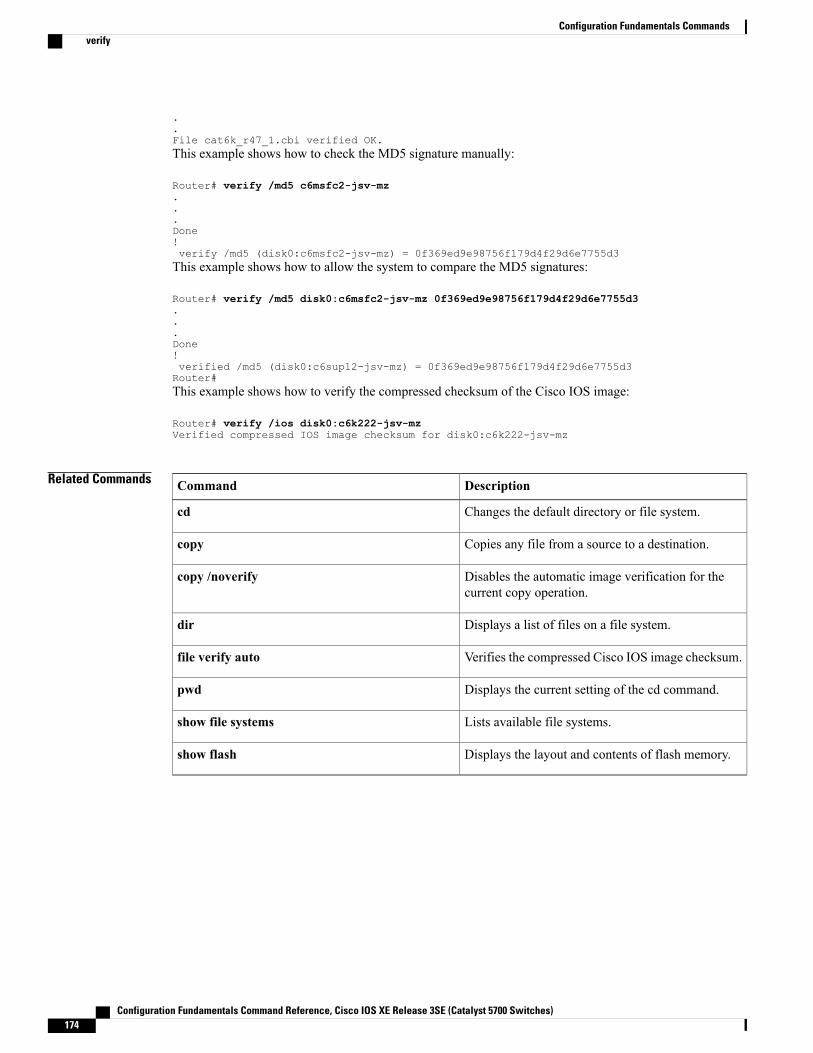
.
.File cat6k_r47_1.cbi verified OK.This example shows how to check the MD5 signature manually:
Router# verify /md5 c6msfc2-jsv-mz...Done!verify /md5 (disk0:c6msfc2-jsv-mz) = 0f369ed9e98756f179d4f29d6e7755d3This example shows how to allow the system to compare the MD5 signatures:
Router# verify /md5 disk0:c6msfc2-jsv-mz 0f369ed9e98756f179d4f29d6e7755d3...Done!verified /md5 (disk0:c6sup12-jsv-mz) = 0f369ed9e98756f179d4f29d6e7755d3Router#This example shows how to verify the compressed checksum of the Cisco IOS image:
Router# verify /ios disk0:c6k222-jsv-mzVerified compressed IOS image checksum for disk0:c6k222-jsv-mz
Related Commands DescriptionCommand
Changes the default directory or file system.cd
Copies any file from a source to a destination.copy
Disables the automatic image verification for thecurrent copy operation.
copy /noverify
Displays a list of files on a file system.dir
Verifies the compressed Cisco IOS image checksum.file verify auto
Displays the current setting of the cd command.pwd
Lists available file systems.show file systems
Displays the layout and contents of flash memory.show flash
Configuration Fundamentals Command Reference, Cisco IOS XE Release 3SE (Catalyst 5700 Switches)174
Configuration Fundamentals Commandsverify
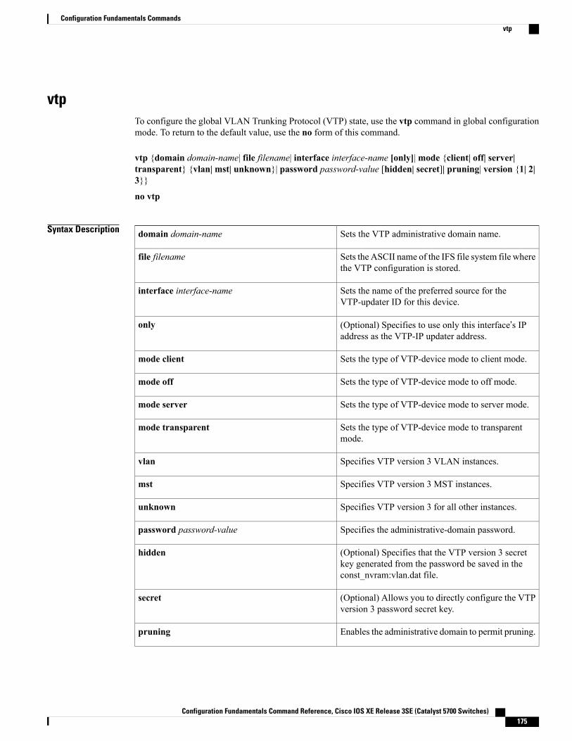
vtpTo configure the global VLAN Trunking Protocol (VTP) state, use the vtp command in global configurationmode. To return to the default value, use the no form of this command.
vtp {domain domain-name| file filename| interface interface-name [only]|mode {client| off| server|transparent} {vlan| mst| unknown}| password password-value [hidden| secret]| pruning| version {1| 2|3}}
no vtp
Syntax Description Sets the VTP administrative domain name.domain domain-name
Sets the ASCII name of the IFS file system file wherethe VTP configuration is stored.
file filename
Sets the name of the preferred source for theVTP-updater ID for this device.
interface interface-name
(Optional) Specifies to use only this interface’s IPaddress as the VTP-IP updater address.
only
Sets the type of VTP-device mode to client mode.mode client
Sets the type of VTP-device mode to off mode.mode off
Sets the type of VTP-device mode to server mode.mode server
Sets the type of VTP-device mode to transparentmode.
mode transparent
Specifies VTP version 3 VLAN instances.vlan
Specifies VTP version 3 MST instances.mst
Specifies VTP version 3 for all other instances.unknown
Specifies the administrative-domain password.password password-value
(Optional) Specifies that the VTP version 3 secretkey generated from the password be saved in theconst_nvram:vlan.dat file.
hidden
(Optional) Allows you to directly configure the VTPversion 3 password secret key.
secret
Enables the administrative domain to permit pruning.pruning
Configuration Fundamentals Command Reference, Cisco IOS XE Release 3SE (Catalyst 5700 Switches) 175
Configuration Fundamentals Commandsvtp
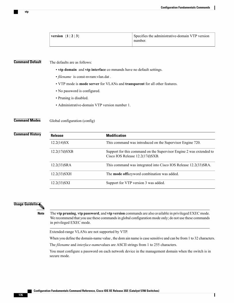
Specifies the administrative-domain VTP versionnumber.
version {1 | 2 | 3}
Command Default The defaults are as follows:
• vtp domain and vtp interface co mmands have no default settings.
• filename is const-nvram:vlan.dat .
• VTP mode ismode server for VLANs and transparent for all other features.
• No password is configured.
• Pruning is disabled.
• Administrative-domain VTP version number 1.
Command Modes Global configuration (config)
Command History ModificationRelease
This command was introduced on the Supervisor Engine 720.12.2(14)SX
Support for this command on the Supervisor Engine 2 was extended toCisco IOS Release 12.2(17d)SXB.
12.2(17d)SXB
This command was integrated into Cisco IOS Release 12.2(33)SRA.12.2(33)SRA
Themode offkeyword combination was added.12.2(33)SXH
Support for VTP version 3 was added.12.2(33)SXI
Usage Guidelines
The vtp pruning, vtp password, and vtp version commands are also available in privileged EXECmode.We recommend that you use these commands in global configurationmode only; do not use these commandsin privileged EXEC mode.
Note
Extended-range VLANs are not supported by VTP.
When you define the domain-name value , the dom ain name is case sensitive and can be from 1 to 32 characters.
The filename and interface-namevalues are ASCII strings from 1 to 255 characters.
You must configure a password on each network device in the management domain when the switch is insecure mode.
Configuration Fundamentals Command Reference, Cisco IOS XE Release 3SE (Catalyst 5700 Switches)176
Configuration Fundamentals Commandsvtp
If you configure VTP in secure mode, the management domain does not function properly if you do notassign a management domain password to each network device in the domain.
Caution
A VTP version 2-capable network device can operate in the same VTP domain as a network device runningVTP version 1 if VTP version 2 is disabled on the VTP version 2-capable network device (VTP version 2 isdisabled by default).
Do not enable VTP version 2 on a network device unless all of the network devices in the same VTP domainare version 2-capable. When you enable VTP version 2 on a network device, all of the version 2-capablenetwork devices in the domain enable VTP version 2.
In a Token Ring environment, you must enable VTP version 2 for VLAN switching to function properly.
Enabling or disabling VTP pruning on a VTP server enables or disables VTP pruning for the entire managementdomain.
Configuring VLANs as pruning eligible or pruning ineligible on a Cisco 7600 series router affects pruningeligibility for those VLANs on that switch only; it does not affect pruning eligibility on all network devicesin the VTP domain.
The vtp password, vtp pruning, and vtp version commands are not placed in startupmemory but are includedin the VTP transparent-mode startup configuration file.
Extended-range VLANs are not supported by VTP.
You can configure the pruning keyword in VTP-server mode; the version keyword is configurable inVTP-server mode or VTP transparent mode.
The password-value argument is an ASCII string from 8 to 64 characters identifying the administrative domainfor the device.
VTP pruning causes information about each pruning-eligible VLAN to be removed fromVTP updates if thereare no stations belonging to that VLAN.
All Cisco 7600 series routers in a VTP domain must run the same version of VTP. VTP version 1 and VTPversion 2 do not operate on Cisco 7600 series routers in the same VTP domain.
If all Cisco 7600 series routers in a domain are VTP version 2-capable, you need only to enable VTP version2 on one Cisco 7600 series router; the version number is then propagated to the other version 2-capable Cisco7600 series routers in the VTP domain.
If you toggle the version 2 mode, certain default VLAN parameters are modified.
If you enter the vtp mode off command, it sets the device to off. If you enter the no vtp mode off command,it resets the device to the VTP server mode.
In VTP version 3, the VTP mode has to be specified on a per-feature basis. Use the vlan andmst keywordsto configure the VTP mode on VLAN and MST instances. To configure the VTP mode for any other feature,use the unknown keyword. When you convert from either VTP version 1 or 2 to version 3, the current modeconfiguration will be preserved.
With VTP version 3, a new method is available for hiding the VTP password from the configuration file.When you use the hidden keyword, the secret key that is generated from the password string is saved in theconst_nvram:vlan.dat file. If you use the secret keyword, you can directly configure the password secret key.By using the secret keyword, you can distribute the password in the secret key format rather than in thecleartext format.
Configuration Fundamentals Command Reference, Cisco IOS XE Release 3SE (Catalyst 5700 Switches) 177
Configuration Fundamentals Commandsvtp
Examples This example shows how to set the device’s management domain:
Router(config)#vtp domain DomainName1This example shows how to specify the file in the IFS-file system where the VTP configuration is stored:
Router(config)#vtp file vtpconfigSetting device to store VLAN database at filename vtpconfig.This example shows how to set the VTP mode to client:
Router(config)#vtp mode clientSetting device to VTP CLIENT mode.This example shows how to disable VTP mode globally:
Router(config)# vtp mode offSetting device to VTP OFF mode.This example shows how to reset the device to the VTP server mode:
Router(config)# no vtp mode offSetting device to VTP OFF mode.
Related Commands DescriptionCommand
Displays the VTP statistics and domain information.show vtp
Enables VTP on a per-port basis.vtp (interface configuration)
Configuration Fundamentals Command Reference, Cisco IOS XE Release 3SE (Catalyst 5700 Switches)178
Configuration Fundamentals Commandsvtp
Related Documents