C613-16092-00 REV A www.alliedtelesis.com How To| Introduction Putting a ring of Ethernet switches at the core of a network is a simple way to increase the network’s resilience—such a network is no longer susceptible to a single point of failure. However, the ring must be protected from Layer 2 loops. Traditionally , STP-based technologies are used to protect rings, but they are relatively slow to recover from link failure. This can create problems for applications that have strict loss requirements, such as voice and video traffic, where the speed of recovery is highly significant. This How To Note describes a fast alternative to STP: Ethernet Protection Switching Ring (EPSR). EPSR enables rings to recover rapidly from link or node failures—within as little as 50 ms, depending on port type and configurati on. This is much faster than STP at 30 seconds or even RSTP at 1to 3 seconds. What information will you find in this document? This How To Note begins by describing EPSR in the following sections: • "How EPSR Works" on page 3 • "Est ablishi ng a Ring " on pa ge 4 • "De tect ing a Faul t" on pag e5 • "Re cov ering fr om a Fau lt" on pa ge 5 • "Res tori ng Normal Operation" on page 7 Next it gives step-by-step configuration details and examples in the following sections: • "How T o Confi gur e EPSR" on page 8 • "Example 1: A Basi c Rin g" on pa ge 10 • "Example 2: A Double Ri ng" on pag e 13 • "Example 3 : EPS R and RSTP " on pa ge 16 • "Example 4: EP SR with Nested VLANs " on page 19 • "Example 5: EPSR wi th Sta ckin g" on pag e 22 • "Example 6: EPSR with an iMAP" on page 25 Configure Ethernet Protection Switching Ring (EPSR) to Protect a Ring from Loops

Welcome message from author
This document is posted to help you gain knowledge. Please leave a comment to let me know what you think about it! Share it to your friends and learn new things together.
Transcript
8/6/2019 Config Epsr Sd A
http://slidepdf.com/reader/full/config-epsr-sd-a 1/54
C613-16092-00 REV A www.alliedtelesis.com
How To|
Introduction
Putting a ring of Ethernet switches at the core of a network is a simple way to increase thenetwork’s resilience—such a network is no longer susceptible to a single point of failure.However, the ring must be protected from Layer 2 loops. Traditionally, STP-basedtechnologies are used to protect rings, but they are relatively slow to recover from link failure. This can create problems for applications that have strict loss requirements, such asvoice and video traffic, where the speed of recovery is highly significant.
This How To Note describes a fast alternative to STP: Ethernet Protection Switching Ring(EPSR). EPSR enables rings to recover rapidly from link or node failures—within as little as50ms, depending on port type and configuration. This is much faster than STP at 30 secondsor even RSTP at 1to 3 seconds.
What information will you find in this document?This How To Note begins by describing EPSR in the following sections:
• "How EPSR Works" on page 3
• "Establishing a Ring" on page 4
• "Detecting a Fault" on page 5
• "Recovering from a Fault" on page 5
• "Restoring Normal Operation" on page 7
Next it gives step-by-step configuration details and examples in the following sections:• "How To Configure EPSR" on page 8
• "Example 1: A Basic Ring" on page 10
• "Example 2: A Double Ring" on page 13
• "Example 3: EPSR and RSTP" on page 16
• "Example 4: EPSR with Nested VLANs" on page 19
• "Example 5: EPSR with Stacking" on page 22
• "Example 6: EPSR with an iMAP" on page 25
Configure Ethernet Protection Switching Ring (EPSR) toProtect a Ring from Loops
8/6/2019 Config Epsr Sd A
http://slidepdf.com/reader/full/config-epsr-sd-a 2/54
Configure Ethernet Protection Switching Ring (EPSR) to Protect a Ring from Loops 2
Next, it discusses important implementation details in the following sections:
• "Classifiers and Hardware Filters" on page 28
• "Ports and Recovery Times" on page 29
• "IGMP Snooping and Recovery Times" on page 30
• "Health Message Priority" on page 30 Finally, it ends with troubleshooting information in the following sections:
• "EPSR State and Settings" on page 31
• "SNMP Traps" on page 33
• "Counters" on page 34
• "Debugging" on page 35
Which products and software versions does itapply to?
EPSR is available on the following Layer 3 switches:
• AT-8948, x900-48FE, x900-48FE-N, AT-9924T, AT-9924SP, and AT-9924T/4SP switches,
running software version 2.8.1 or later
• AT-9924Ts, x900-24XT, and x900-24XT-N switches running software version 3.1.1 or
later
EPSR on these switches is also compatible with EPSR on Allied Telesis’ Multiservice Access
Platforms (iMAPs).
8/6/2019 Config Epsr Sd A
http://slidepdf.com/reader/full/config-epsr-sd-a 3/54
Configure Ethernet Protection Switching Ring (EPSR) to Protect a Ring from Loops 3
How EPSR Works
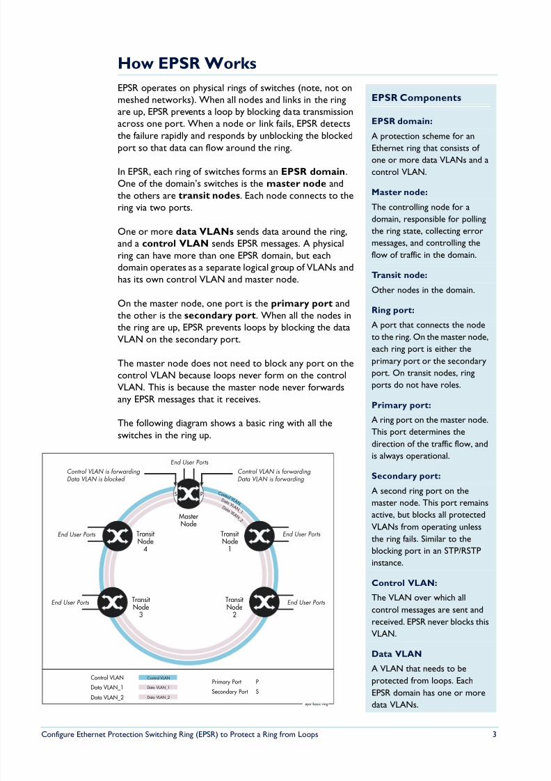
EPSR operates on physical rings of switches (note, not onmeshed networks). When all nodes and links in the ringare up, EPSR prevents a loop by blocking data transmissionacross one port. When a node or link fails, EPSR detects
the failure rapidly and responds by unblocking the blockedport so that data can flow around the ring.
In EPSR, each ring of switches forms an EPSR domain.One of the domain’s switches is the master node andthe others are transit nodes. Each node connects to thering via two ports.
One or more data VLANs sends data around the ring,and a control VLAN sends EPSR messages. A physicalring can have more than one EPSR domain, but eachdomain operates as a separate logical group of VLANs andhas its own control VLAN and master node.
On the master node, one port is the primary port andthe other is the secondary port. When all the nodes inthe ring are up, EPSR prevents loops by blocking the dataVLAN on the secondary port.
The master node does not need to block any port on thecontrol VLAN because loops never form on the controlVLAN. This is because the master node never forwardsany EPSR messages that it receives.
The following diagram shows a basic ring with all theswitches in the ring up.
EPSR Components
EPSR domain:
A protection scheme for anEthernet ring that consists of
one or more data VLANs and a
control VLAN.
Master node:
The controlling node for a
domain, responsible for polling
the ring state, collecting error
messages, and controlling the
flow of traffic in the domain.
Transit node:
Other nodes in the domain.
Ring port:
A port that connects the node
to the ring. On the master node,
each ring port is either the
primary port or the secondary
port. On transit nodes, ring
ports do not have roles.
Primary port:
A ring port on the master node.
This port determines the
direction of the traffic flow, and
is always operational.
Secondary port:
A second ring port on the
master node. This port remains
active, but blocks all protected
VLANs from operating unless
the ring fails. Similar to the
blocking port in an STP/RSTPinstance.
Control VLAN:
The VLAN over which all
control messages are sent and
received. EPSR never blocks this
VLAN.
Data VLAN
A VLAN that needs to be
protected from loops. EachEPSR domain has one or more
data VLANs.
D a t a V L A N _2
D a t a V L A N _1
C o n t r o l V L A N
MasterNode
Transit Node
1
Transit Node
4
Transit Node
2
Data VLAN_1
Control VLAN
Primary Port
Transit Node
3
epsr-basic-ring
Control VLAN
Data VLAN_2
PSSecondary Port
Control VLAN is forwardingData VLAN is forwarding
End User Ports
Data VLAN_2
Control VLAN is forwardingData VLAN is blocked
Data VLAN_1
PS
End User Ports
End User Ports
End User Ports
End User Ports
8/6/2019 Config Epsr Sd A
http://slidepdf.com/reader/full/config-epsr-sd-a 4/54
Configure Ethernet Protection Switching Ring (EPSR) to Protect a Ring from Loops 4
Establishing a Ring
Once you have configured EPSR on the switches, the following steps complete the EPSR ring:
1. The master node creates an EPSR Health message and sends it out the primary port. Thisincrements the master node’s Transmit: Health counter in the show epsr count command.
2. The first transit node receives the Health message on one of its two ring ports and, usinga hardware filter, sends the message out its other ring port.
Note that transit nodes never generate Health messages, only receive them and forwardthem with their switching hardware. This does not increment the transit node’s Transmit:Health counter. However, it does increment the Transmit counter in the show switch
port command.
The hardware filter also copies the Health message to the CPU. This increments thetransit node’s Receive: Health counter. The CPU processes this message as required bythe state machines, but does not send the message anywhere because the switchinghardware has already done this.
3. The Health message continues around the rest of the transit nodes, being copied to theCPU and forwarded in the switching hardware.
4. The master node eventually receives the Health message on its secondary port. Themaster node's hardware filter copies the packet to the CPU (which increments the masternode’s Receive: Health counter). Because the master received the Health message on itssecondary port, it knows that all links and nodes in the ring are up.
When the master node receives the Health message back on its secondary port, it resetsthe Failover timer. If the Failover timer expires before the master node receives the Healthmessage back, it concludes that the ring must be broken.
Note that the master node does not send that particular Health message out again. If itdid, the packet would be continuously flooded around the ring. Instead, the master nodegenerates a new Health message when the Hello timer expires.
8/6/2019 Config Epsr Sd A
http://slidepdf.com/reader/full/config-epsr-sd-a 5/54
Configure Ethernet Protection Switching Ring (EPSR) to Protect a Ring from Loops 5
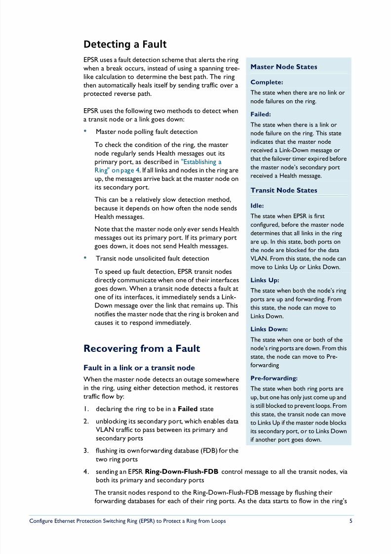
Detecting a Fault
EPSR uses a fault detection scheme that alerts the ringwhen a break occurs, instead of using a spanning tree-like calculation to determine the best path. The ringthen automatically heals itself by sending traffic over a
protected reverse path.
EPSR uses the following two methods to detect whena transit node or a link goes down:
• Master node polling fault detection
To check the condition of the ring, the masternode regularly sends Health messages out itsprimary port, as described in "Establishing aRing" on page 4. If all links and nodes in the ring areup, the messages arrive back at the master node onits secondary port.
This can be a relatively slow detection method,because it depends on how often the node sendsHealth messages.
Note that the master node only ever sends Healthmessages out its primary port. If its primary portgoes down, it does not send Health messages.
• Transit node unsolicited fault detection
To speed up fault detection, EPSR transit nodesdirectly communicate when one of their interfaces
goes down. When a transit node detects a fault atone of its interfaces, it immediately sends a Link-Down message over the link that remains up. Thisnotifies the master node that the ring is broken andcauses it to respond immediately.
Recovering from a Fault
Fault in a link or a transit node
When the master node detects an outage somewhere
in the ring, using either detection method, it restorestraffic flow by:
1. declaring the ring to be in a Failed state
2. unblocking its secondary port, which enables dataVLAN traffic to pass between its primary andsecondary ports
3. flushing its own forwarding database (FDB) for thetwo ring ports
4. sending an EPSR Ring-Down-Flush-FDB control message to all the transit nodes, viaboth its primary and secondary ports
The transit nodes respond to the Ring-Down-Flush-FDB message by flushing theirforwarding databases for each of their ring ports. As the data starts to flow in the ring’s
Master Node States
Complete:
The state when there are no link or
node failures on the ring.
Failed:
The state when there is a link or
node failure on the ring. This state
indicates that the master node
received a Link-Down message or
that the failover timer expired before
the master node’s secondary port
received a Health message.
Transit Node States
Idle:
The state when EPSR is first
configured, before the master node
determines that all links in the ring
are up. In this state, both ports on
the node are blocked for the data
VLAN. From this state, the node can
move to Links Up or Links Down.
Links Up:
The state when both the node’s ringports are up and forwarding. From
this state, the node can move to
Links Down.
Links Down:
The state when one or both of the
node’s ring ports are down. From this
state, the node can move to Pre-
forwarding
Pre-forwarding:
The state when both ring ports areup, but one has only just come up and
is still blocked to prevent loops. From
this state, the transit node can move
to Links Up if the master node blocks
its secondary port, or to Links Down
if another port goes down.
8/6/2019 Config Epsr Sd A
http://slidepdf.com/reader/full/config-epsr-sd-a 6/54
Configure Ethernet Protection Switching Ring (EPSR) to Protect a Ring from Loops 6
new configuration, the nodes (master and transit) re-learn their layer 2 addresses. Duringthis period, the master node continues to send Health messages over the control VLAN.This situation continues until the faulty link or node is repaired.
For a multidomain ring, this process occurs separately for each domain within the ring.
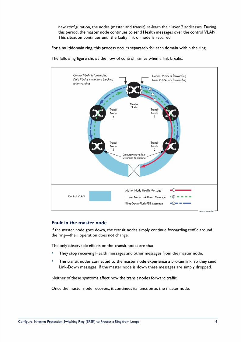
The following figure shows the flow of control frames when a link breaks.
Fault in the master node
If the master node goes down, the transit nodes simply continue forwarding traffic aroundthe ring—their operation does not change.
The only observable effects on the transit nodes are that:
• They stop receiving Health messages and other messages from the master node.
• The transit nodes connected to the master node experience a broken link, so they send
Link-Down messages. If the master node is down these messages are simply dropped.
Neither of these symtoms affect how the transit nodes forward traffic.
Once the master node recovers, it continues its function as the master node.
MasterNode
Transit Node
1
Transit Node
4
Transit Node
2
Control VLAN
Ring-Down-Flush-FDB Message
Transit Node
3
Control VLAN is forwarding
Data VLANs are forwarding
Control VLAN is forwarding
Data VLANs move from blocking
to forwarding
Data ports move fromfowarding to blocking
Transit Node Link-Down Message
Master Node Health Message
PS
epsr-broken-ring
1
2
3
1
2
3
8/6/2019 Config Epsr Sd A
http://slidepdf.com/reader/full/config-epsr-sd-a 7/54
Configure Ethernet Protection Switching Ring (EPSR) to Protect a Ring from Loops 7
Restoring Normal Operation
Master Node
Once the fault has been fixed, the master node’s Health messages traverse the whole ring andarrive at the master node’s secondary port. The master node then restores normalconditions by:
1. declaring the ring to be in a state of Complete
2. blocking its secondary port for data VLAN traffic (but not for the control VLAN)
3. flushing its forwarding database for its two ring ports
4. sending a Ring-Up-Flush-FDB message from its primary port, to all transit nodes.
Transit Nodes with One Port Down
As soon as the fault has been fixed, the transit nodes on each side of the (previously) faultylink section detect that link connectivity has returned. They change their ring port state fromLinks Down to Pre-Forwarding, and wait for the master node to send a Ring-Up-Flush-FDB
control message.
Once these transit nodes receive the Ring-Up-Flush-FDB message, they:
• flush the forwarding databases for both their ring ports
• change the state of their ports from blocking to forwarding for the data VLAN, which
allows data to flow through their previously-blocked ring ports
The transit nodes do not start forwarding traffic on the previously-down ports until afterthey receive the Ring-Up-Flush-FDB message. This makes sure the previously-down transitnode ports stay blocked until after the master node blocks its secondary port. Otherwise,
the ring could form a loop because it had no blocked ports.
Transit Nodes with Both Ports Down
The Allied Telesis implementation includes an extra feature to improve handling of doublelink failures. If both ports on a transit node are down and one port comes up, the node:
1. puts the port immediately into the forwarding state and starts forwarding data out thatport. It does not need to wait, because the node knows there is no loop in the ring— because the other ring port on the node is down
2. remains in the Links Down state
3. starts a DoubleFailRecovery timer with a timeout of four seconds
4. waits for the timer to expire. At that time, if one port is still up and one is still down, thetransit node sends a Ring-Up-Flush-FDB message out the port that is up. This message isusually called a “Fake Ring Up message”.
Sending this message allows any ports on other transit nodes that are blocking or in the Pre-forwarding state to move to forwarding traffic in the Links Up state. The timer delay lets thedevice at the other end of the link that came up configure its port appropriately, so that it isready to receive the transmitted message.
Note that the master node would not send a Ring-Up-Flush-FDB message in thesecircumstances, because the ring is not in a state of Complete. The master node’s secondary
port remains unblocked.
8/6/2019 Config Epsr Sd A
http://slidepdf.com/reader/full/config-epsr-sd-a 8/54
Configure Ethernet Protection Switching Ring (EPSR) to Protect a Ring from Loops 8
How To Configure EPSR
This section first outlines, step-by-step, how to configure EPSR. Then it discusses changingthe settings for the control VLAN, if you need to do this after initial configuration.
Configuring EPSR
EPSR does not in itself limit the number of nodes that can exist on any given ring. Each switchcan participate in up to 16 r ings.
If you already have a ring in a live network, disconnect the cable between any two of thenodes before you start configuring EPSR, to prevent a loop.
On each switch, perform the following configuration steps. Configuration of the master nodeand each transit node is very similar.
Create the control VLAN and add the ring ports to it as tagged ports. Use thecommands:
create vlan=control-vlan-name vid=control-vid
add vlan=control-vid port=ring-ports frame=tagged
Note that you can use trunk groups for the ring ports.
Create the data VLAN (or VLANs—you can have as many as you want) and add thering ports as tagged ports. Use the commands:
create vlan=data-vlan-name vid=data-vid
add vlan=data-vid port=ring-ports frame=tagged
The two ring ports must belong to the control VLAN and all data VLANs.
If you leave all the ring ports in the default VLAN (vlan1), they will create a loop, unlessvlan1 is part of the EPSR domain. To avoid loops, you need to do one of the following:
• make vlan1 a data VLAN, or
• remove the ring ports from vlan1, or
1. Connect your switches into a ring
2. On each switch, configure EPSR
i. Configure the control VLAN
ii. Configure the data VLAN
iii. Remove the ring ports from the default VLAN
8/6/2019 Config Epsr Sd A
http://slidepdf.com/reader/full/config-epsr-sd-a 9/54
Configure Ethernet Protection Switching Ring (EPSR) to Protect a Ring from Loops 9
• remove at least one of the ring ports from vlan1 on at least one of the switches.
We do not recommend this option, because the action you have taken is less
obvious when maintaining the network later.
In this How To Note, we remove the ring ports from the default VLAN. Use thecommand:
delete vlan=1 port=ring-ports
Create the domain, specifying whether the switch is the master node or a transit node.Also specify which VLAN is the control VLAN, and on the master node which port isthe primary port. Use one of the following commands:
On the master node:
create epsr=name mode=master controlvlan=control-vlan-name primaryport= port-number
On each transit node:
create epsr=name mode=transit controlvlan=control-vlan-name
Add the data VLAN to the domain. Use the command:
add epsr=name datavlan=data-vlan-name
Enable the domain on each switch. Use the command:
enable epsr=name
On each switch, configure the other ports and protocols that make up your network.
Modifying the Control VLAN
You cannot modify the control VLAN while EPSR is enabled. If you try to remove or add
ports to the control VLAN, the switch generates an error message as follows:
Disable the EPSR domain and then make the required changes. Note that disabling EPSR willcreate a loop, so is not recommended on a network with live data. Of course, in a livenetwork, you can manually prevent a loop by disconnecting the cable between any two of thenodes.
iv. Configure the EPSR domain
v. Enable EPSR
3. Configure other ports and protocols as required
Manager> delete vlan=1000 port=1Error (3089409): VLAN 1000 is a control VLAN in EPSR and cannot be modified
8/6/2019 Config Epsr Sd A
http://slidepdf.com/reader/full/config-epsr-sd-a 10/54
Configure Ethernet Protection Switching Ring (EPSR) to Protect a Ring from Loops 10
Example 1: A Basic Ring
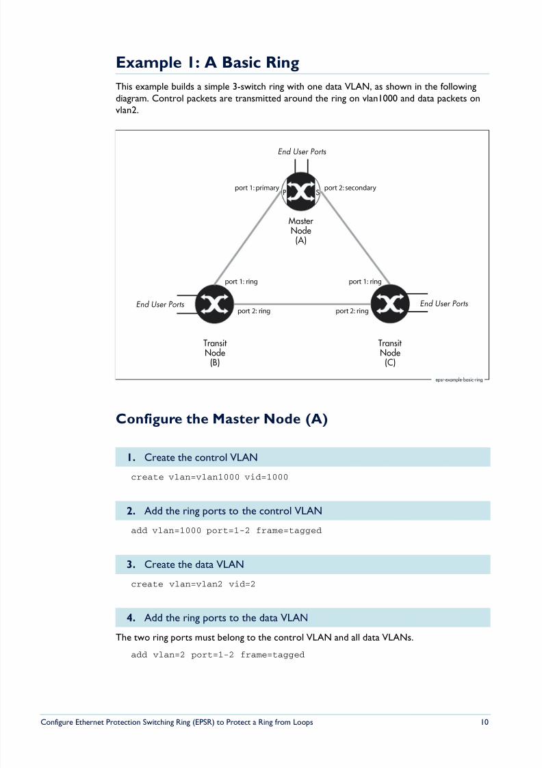
This example builds a simple 3-switch ring with one data VLAN, as shown in the followingdiagram. Control packets are transmitted around the ring on vlan1000 and data packets onvlan2.
Configure the Master Node (A)
create vlan=vlan1000 vid=1000
add vlan=1000 port=1-2 frame=tagged
create vlan=vlan2 vid=2
The two ring ports must belong to the control VLAN and all data VLANs.
add vlan=2 port=1-2 frame=tagged
1. Create the control VLAN
2. Add the ring ports to the control VLAN
3. Create the data VLAN
4. Add the ring ports to the data VLAN
MasterNode(A)
Transit Node(C)
Transit Node
(B)
epsr-example-basic-ring
End User Ports
SP
End User PortsEnd User Ports
port 1: primary port 2: secondary
port 1: ring
port 2: ring
port 1: ring
port 2: ring
8/6/2019 Config Epsr Sd A
http://slidepdf.com/reader/full/config-epsr-sd-a 11/54
Configure Ethernet Protection Switching Ring (EPSR) to Protect a Ring from Loops 11
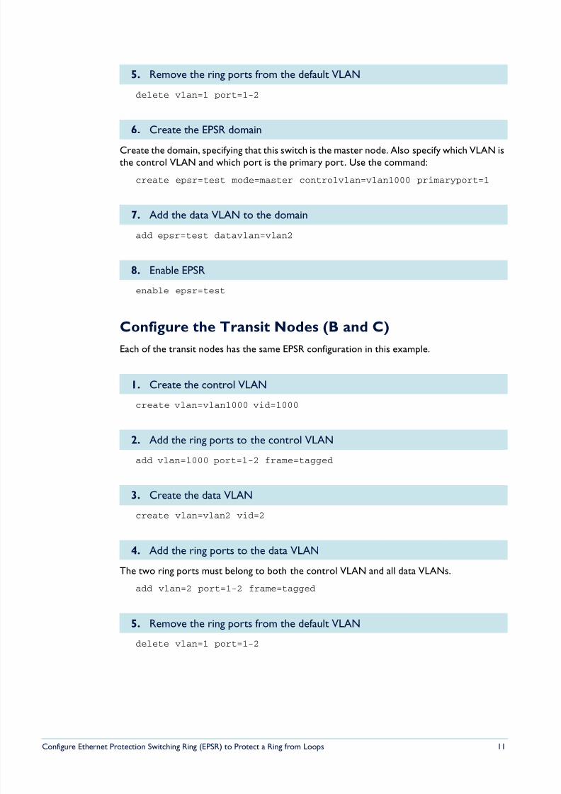
delete vlan=1 port=1-2
Create the domain, specifying that this switch is the master node. Also specify which VLAN isthe control VLAN and which port is the primary port. Use the command:
create epsr=test mode=master controlvlan=vlan1000 primaryport=1
add epsr=test datavlan=vlan2
enable epsr=test
Configure the Transit Nodes (B and C)
Each of the transit nodes has the same EPSR configuration in this example.
create vlan=vlan1000 vid=1000
add vlan=1000 port=1-2 frame=tagged
create vlan=vlan2 vid=2
The two ring ports must belong to both the control VLAN and all data VLANs.
add vlan=2 port=1-2 frame=tagged
delete vlan=1 port=1-2
5. Remove the ring ports from the default VLAN
6. Create the EPSR domain
7. Add the data VLAN to the domain
8. Enable EPSR
1. Create the control VLAN
2. Add the ring ports to the control VLAN
3. Create the data VLAN
4. Add the ring ports to the data VLAN
5. Remove the ring ports from the default VLAN
8/6/2019 Config Epsr Sd A
http://slidepdf.com/reader/full/config-epsr-sd-a 12/54
Configure Ethernet Protection Switching Ring (EPSR) to Protect a Ring from Loops 12
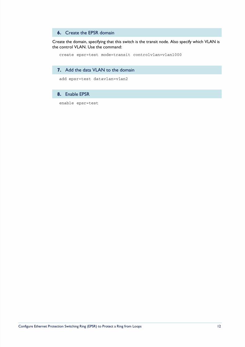
Create the domain, specifying that this switch is the transit node. Also specify which VLAN isthe control VLAN. Use the command:
create epsr=test mode=transit controlvlan=vlan1000
add epsr=test datavlan=vlan2
enable epsr=test
6. Create the EPSR domain
7. Add the data VLAN to the domain
8. Enable EPSR
8/6/2019 Config Epsr Sd A
http://slidepdf.com/reader/full/config-epsr-sd-a 13/54
Configure Ethernet Protection Switching Ring (EPSR) to Protect a Ring from Loops 13
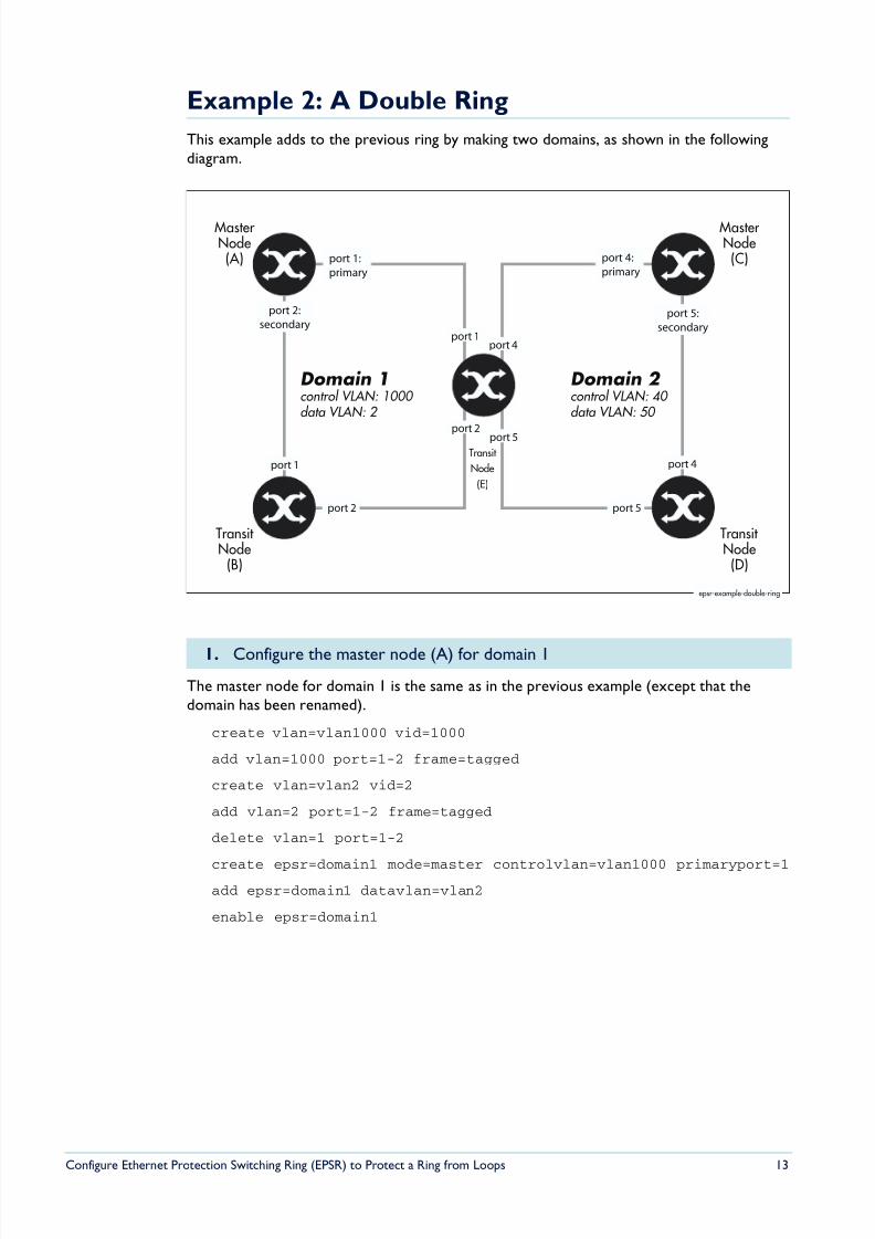
Example 2: A Double Ring
This example adds to the previous ring by making two domains, as shown in the followingdiagram.
The master node for domain 1 is the same as in the previous example (except that thedomain has been renamed).
create vlan=vlan1000 vid=1000
add vlan=1000 port=1-2 frame=tagged
create vlan=vlan2 vid=2
add vlan=2 port=1-2 frame=tagged
delete vlan=1 port=1-2
create epsr=domain1 mode=master controlvlan=vlan1000 primaryport=1add epsr=domain1 datavlan=vlan2
enable epsr=domain1
1. Configure the master node (A) for domain 1
MasterNode(A)
Transit Node(D)
Transit Node
(B)
epsr-example-double-ring
port 2:
secondary
MasterNode(C)
port 1
Domain 1control VLAN: 1000
data VLAN: 2
Domain 2 control VLAN: 40
data VLAN: 50
port 2
port 1
port 2
port 1:
primary
port 5:
secondary
port 4:
primary
port 4
port 5
port 4
port 5
Transit
Node
(E)
8/6/2019 Config Epsr Sd A
http://slidepdf.com/reader/full/config-epsr-sd-a 14/54
Configure Ethernet Protection Switching Ring (EPSR) to Protect a Ring from Loops 14
This transit node is the same as in the previous example (except that the domain has beenrenamed).
create vlan=vlan1000 vid=1000
add vlan=1000 port=1-2 frame=tagged
create vlan=vlan2 vid=2
add vlan=2 port=1-2 frame=tagged
delete vlan=1 port=1-2
create epsr=domain1 mode=transit controlvlan=vlan1000
add epsr=domain1 datavlan=vlan2
enable epsr=domain1
Configure the control VLAN:
create vlan=vlan40 vid=40
add vlan=40 port=4-5 frame=tagged
Configure the data VLAN:
create vlan=vlan50 vid=50
add vlan=50 port=4-5 frame=tagged
Remove the ring ports from the default VLAN:delete vlan=1 port=4-5
Configure EPSR:
create epsr=domain2 mode=master controlvlan=vlan40 primaryport=4
add epsr=domain2 datavlan=vlan50
enable epsr=domain2
Configure the control VLAN:
create vlan=vlan40 vid=40
add vlan=40 port=4-5 frame=tagged
Configure the data VLAN:
create vlan=vlan50 vid=50
add vlan=50 port=4-5 frame=tagged
Remove the ring ports from the default VLAN:
delete vlan=1 port=4-5
2. Configure the transit node (B) that belongs just to domain 1
3. Configure the master node (C) for domain 2
4. Configure the transit node (D) that belongs just to domain 2
8/6/2019 Config Epsr Sd A
http://slidepdf.com/reader/full/config-epsr-sd-a 15/54
Configure Ethernet Protection Switching Ring (EPSR) to Protect a Ring from Loops 15
Configure EPSR:
create epsr=domain2 mode=transit controlvlan=vlan40
add epsr=domain2 datavlan=vlan50
enable epsr=domain2
Configure the control VLAN for domain 1:
create vlan=vlan1000 vid=1000
add vlan=1000 port=1-2 frame=tagged
Configure the control VLAN for domain 2:
create vlan=vlan40 vid=40
add vlan=40 port=4-5 frame=tagged
Configure the data VLAN for domain 1:
create vlan=vlan2 vid=2
add vlan=2 port=1-2 frame=tagged
Configure the data VLAN for domain 2:
create vlan=vlan50 vid=50
add vlan=50 port=4-5 frame=tagged
Remove the ring ports from the default VLAN:
delete vlan=1 port=1-2,4-5
Configure EPSR for domain 1:
create epsr=domain1 mode=transit controlvlan=vlan1000
add epsr=domain1 datavlan=vlan2
enable epsr=domain1
Configure EPSR for domain 2:
create epsr=domain2 mode=transit controlvlan=vlan40
add epsr=domain2 datavlan=vlan50enable epsr=domain2
5. Configure the transit node (E) that belongs to both domains
8/6/2019 Config Epsr Sd A
http://slidepdf.com/reader/full/config-epsr-sd-a 16/54
Configure Ethernet Protection Switching Ring (EPSR) to Protect a Ring from Loops 16
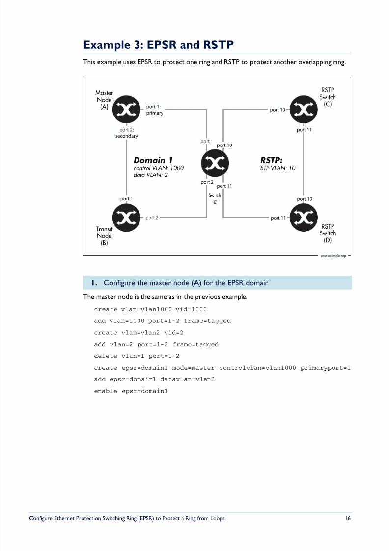
Example 3: EPSR and RSTP
This example uses EPSR to protect one ring and RSTP to protect another overlapping ring.
The master node is the same as in the previous example.
create vlan=vlan1000 vid=1000
add vlan=1000 port=1-2 frame=tagged
create vlan=vlan2 vid=2
add vlan=2 port=1-2 frame=tagged
delete vlan=1 port=1-2
create epsr=domain1 mode=master controlvlan=vlan1000 primaryport=1
add epsr=domain1 datavlan=vlan2
enable epsr=domain1
1. Configure the master node (A) for the EPSR domain
MasterNode(A)
Transit Node
(B)
epsr-example-rstp
port 2:
secondary
port 1
Domain 1control VLAN: 1000
data VLAN: 2
RSTP: STP VLAN: 10
port 2
port 1
port 2
port 1:
primary
port 10
port 11
RSTP
Switch(C)
RSTPSwitch
(D)
Switch
(E)
port 10
port 11
port 10
port 11
8/6/2019 Config Epsr Sd A
http://slidepdf.com/reader/full/config-epsr-sd-a 17/54
Configure Ethernet Protection Switching Ring (EPSR) to Protect a Ring from Loops 17
This transit node (B) is the same as in the previous example.
create vlan=vlan1000 vid=1000
add vlan=1000 port=1-2 frame=tagged
create vlan=vlan2 vid=2
add vlan=2 port=1-2 frame=tagged
delete vlan=1 port=1-2
create epsr=domain1 mode=transit controlvlan=vlan1000
add epsr=domain1 datavlan=vlan2
enable epsr=domain1
Switches C and D have the same configuration in this example.
Configure the STP VLAN:
create vlan=vlan10 vid=10
add vlan=10 port=10-11 frame=tagged
Remove the STP VLAN’s ports from the default VLAN:
delete vlan=1 port=10-11
Configure STP:
create stp=example
add stp=example vlan=vlan10
enable stp=example
set stp=example mode=rapid
Configure the control VLAN for EPSR:
create vlan=vlan1000 vid=1000
add vlan=1000 port=1-2 frame=tagged
Configure the data VLAN for EPSR:
create vlan=vlan2 vid=2
add vlan=2 port=1-2 frame=tagged
Remove the ring ports from the default VLAN:
delete vlan=1 port=1-2
2. Configure the transit node (B) that belongs just to the EPSR domain
3. Configure the switches that belong to the RSTP instance (C and D)
4. Configure switch E for EPSR and RSTP
8/6/2019 Config Epsr Sd A
http://slidepdf.com/reader/full/config-epsr-sd-a 18/54
Configure Ethernet Protection Switching Ring (EPSR) to Protect a Ring from Loops 18
Configure EPSR:
create epsr=domain1 mode=transit controlvlan=vlan1000
add epsr=domain1 datavlan=vlan2
enable epsr=domain1
Configure the STP VLAN:create vlan=vlan10 vid=10
add vlan=10 port=10-11 frame=tagged
Remove the STP VLAN’s ports from the default VLAN:
delete vlan=1 port=10-11
Configure STP:
create stp=example
add stp=example vlan=vlan10
enable stp=example
set stp=example mode=rapid
8/6/2019 Config Epsr Sd A
http://slidepdf.com/reader/full/config-epsr-sd-a 19/54
Configure Ethernet Protection Switching Ring (EPSR) to Protect a Ring from Loops 19
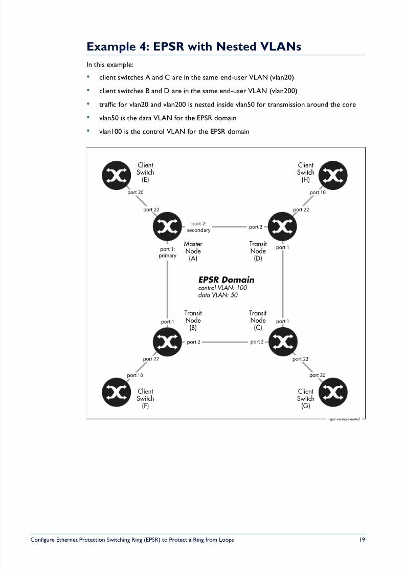
Example 4: EPSR with Nested VLANs
In this example:
• client switches A and C are in the same end-user VLAN (vlan20)
• client switches B and D are in the same end-user VLAN (vlan200)
• traffic for vlan20 and vlan200 is nested inside vlan50 for transmission around the core
• vlan50 is the data VLAN for the EPSR domain
• vlan100 is the control VLAN for the EPSR domain
MasterNode(A)
Transit Node(C)
Transit Node
(B)
epsr-example-nested
port 2:
secondary
Transit Node(D)
port 1
EPSR Domaincontrol VLAN: 100
data VLAN: 50
port 2
port 1:
primary
port 1
port 2port 2
port 1
Client Switch
(E)
Client Switch
(H)
Client
Switch(F)
Client
Switch(G)
port 22 port 22port 22
port 10 port 20
port 22port 22
port 20 port 10
8/6/2019 Config Epsr Sd A
http://slidepdf.com/reader/full/config-epsr-sd-a 20/54
Configure Ethernet Protection Switching Ring (EPSR) to Protect a Ring from Loops 20
Configure the EPSR control VLAN:
create vlan=vlan100 vid=100
add vlan=100 port=1-2 frame=tagged
Configure vlan50. This VLAN acts as both the nested VLAN and the EPSR data VLAN. Thefollowing commands create vlan50 and configure it as a nested VLAN:
create vlan=vlan50 vid=50 nested
add vlan=50 port=22 nestedtype=customer
add vlan=50 port=1-2 nestedtype=core
Remove the ring ports from the default VLAN:
delete vlan=1 port=1-2
Configure EPSR:
create epsr=example mode=master controlvlan=vlan100 primaryport=1
add epsr=example datavlan=vlan50
enable epsr=example
Each of the transit nodes has the same EPSR configuration in this example.
Configure the EPSR control VLAN:create vlan=vlan100 vid=100
add vlan=100 port=1-2 frame=tagged
Configure vlan50, which acts as both the nested VLAN and the EPSR data VLAN:
create vlan=vlan50 vid=50 nested
add vlan=50 port=22 nestedtype=customer
add vlan=50 port=1-2 nestedtype=core
Remove the ring ports from the default VLAN:
delete vlan=1 port=1-2
Configure EPSR:
create epsr=example mode=transit controlvlan=vlan100
add epsr=example datavlan=vlan50
enable epsr=example
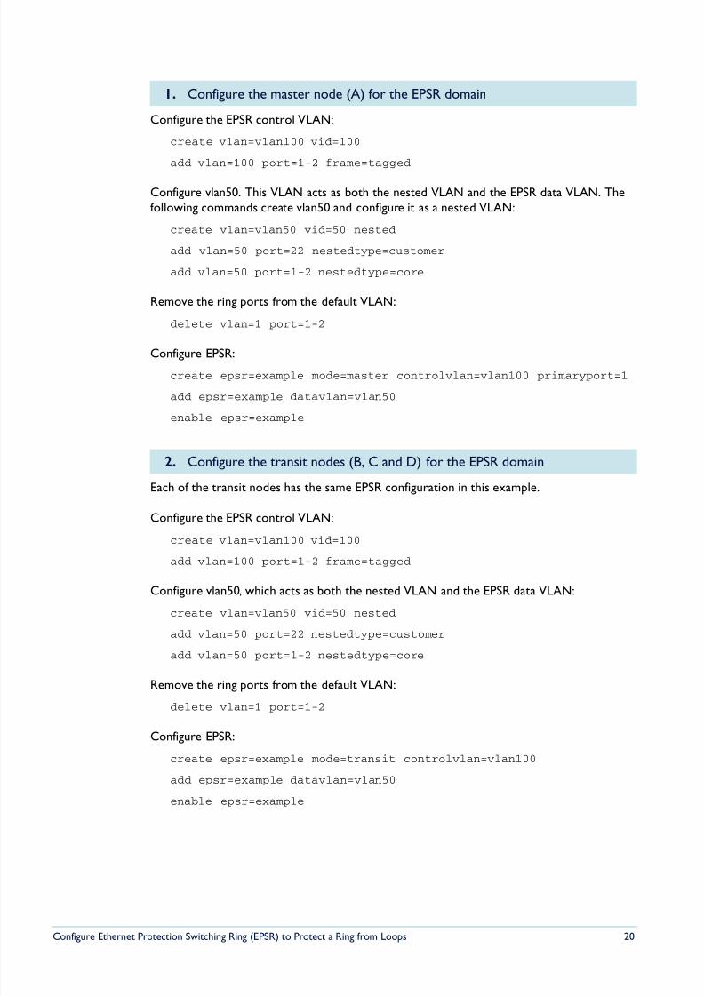
1. Configure the master node (A) for the EPSR domain
2. Configure the transit nodes (B, C and D) for the EPSR domain
8/6/2019 Config Epsr Sd A
http://slidepdf.com/reader/full/config-epsr-sd-a 21/54
Configure Ethernet Protection Switching Ring (EPSR) to Protect a Ring from Loops 21
create vlan=vlan20 vid=20
add vlan=20 port=20 frame=tagged
enable ip
add ip interface=vlan20 ip=192.168.20.10
create vlan=vlan200 vid=200
add vlan=200 port=10 frame=tagged
enable ip
add ip interface=vlan200 ip=192.168.200.1
create vlan=vlan20 vid=20
add vlan=20 port=20 frame=tagged
enable ip
add ip int=vlan20 ip=192.168.20.1
create vlan=vlan200 vid=200add vlan=200 port=10 frame=tagged
enable ip
add ip interface=vlan200 ip=192.168.200.10
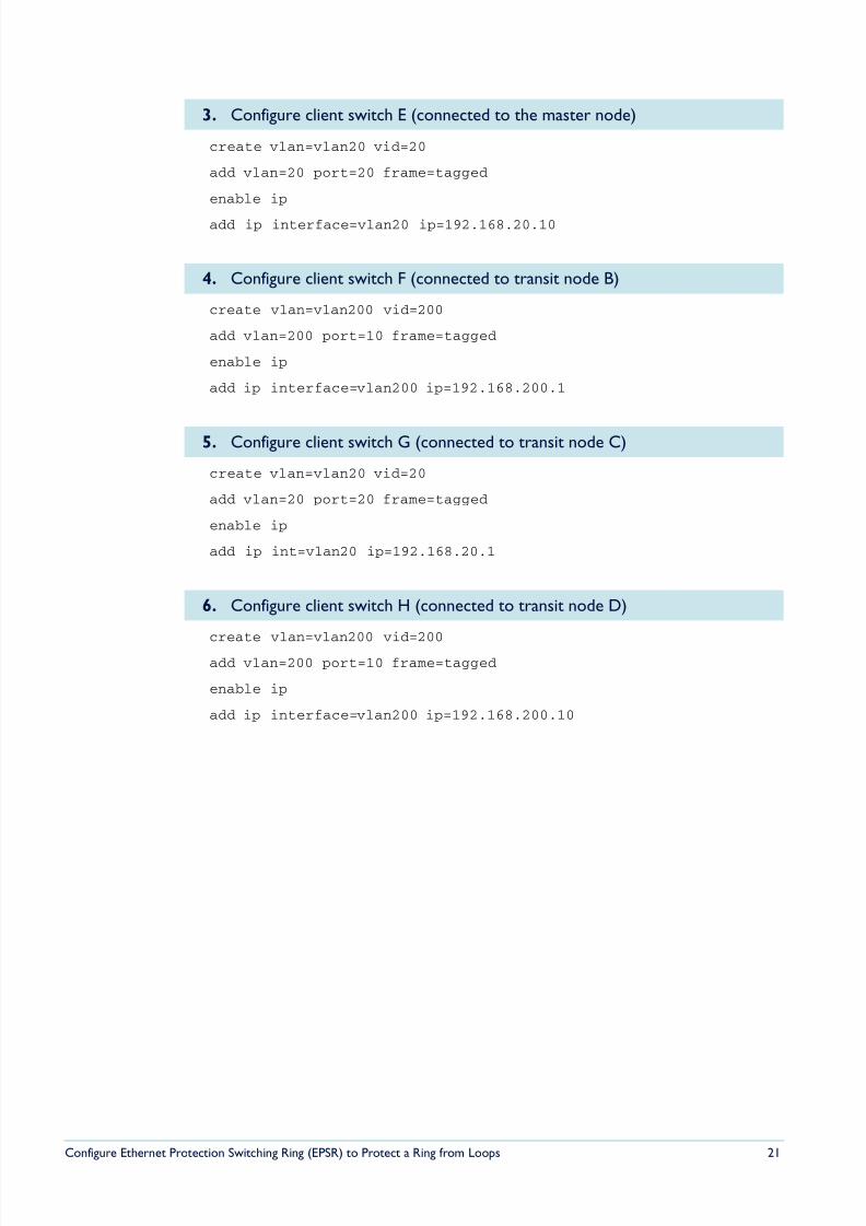
3. Configure client switch E (connected to the master node)
4. Configure client switch F (connected to transit node B)
5. Configure client switch G (connected to transit node C)
6. Configure client switch H (connected to transit node D)
8/6/2019 Config Epsr Sd A
http://slidepdf.com/reader/full/config-epsr-sd-a 22/54
Configure Ethernet Protection Switching Ring (EPSR) to Protect a Ring from Loops 22
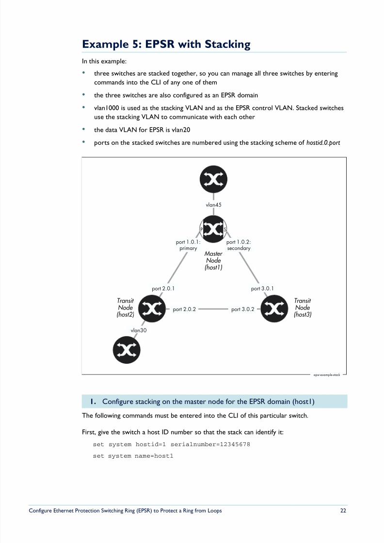
Example 5: EPSR with Stacking
In this example:
• three switches are stacked together, so you can manage all three switches by entering
commands into the CLI of any one of them
• the three switches are also configured as an EPSR domain
• vlan1000 is used as the stacking VLAN and as the EPSR control VLAN. Stacked switches
use the stacking VLAN to communicate with each other
• the data VLAN for EPSR is vlan20
• ports on the stacked switches are numbered using the stacking scheme of hostid.0.port
The following commands must be entered into the CLI of this particular switch.
First, give the switch a host ID number so that the stack can identify it:
set system hostid=1 serialnumber=12345678
set system name=host1
1. Configure stacking on the master node for the EPSR domain (host1)
Master Node (host1)
Transit Node (host3)
Transit Node (host2)
epsr-example-stack
SP
port 1.0.1:primary
port 1.0.2:secondary
vlan45
vlan30
port 2.0.1
port 2.0.2 port 3.0.2
port 3.0.1
8/6/2019 Config Epsr Sd A
http://slidepdf.com/reader/full/config-epsr-sd-a 23/54
Configure Ethernet Protection Switching Ring (EPSR) to Protect a Ring from Loops 23
Create the stacking VLAN and add the ring ports to it. Note the port numbering notation— these are ports 1 and 2 on stacking host 1. Because this VLAN will also be the EPSR controlVLAN, this step also adds the ring ports to the control VLAN. Use the commands:
create vlan=stack vid=1000
add vlan=1000 port=1.0.1-1.0.2 frame=tagged
Add the stacking VLAN to the stack and enable stacking:
add stack interface=vlan1000
enable stack
These commands must be entered into the CLI of this particular switch.
set system hostid=2 serialnumber=23456789
set system name=host2
create vlan=stack vid=1000
add vlan=1000 port=2.0.1-2.0.2 frame=tagged
add stack interface=vlan1000
enable stack
These commands must be entered into the CLI of this particular switch.
set system hostid=3 serialnumber=34567890
set system name=host3
create vlan=stack vid=1000
add vlan=1000 port=3.0.1-3.0.2 frame=tagged
add stack interface=vlan1000
enable stack
The stack now exists, so you can configure all three switches from the CLI of the masternode (or any other of the switches). However, the ports and IP addresses are different foreach switch, so you need to make most of the commands host-directed.
Create the EPSR data VLAN. This command will propagate to all three switches:
create vlan=vlan20 vid=20
2. Configure stacking on the first transit node (host2)
3. Configure stacking on the second transit node (host3)
4. Configure the other VLANs on the stacked switches
8/6/2019 Config Epsr Sd A
http://slidepdf.com/reader/full/config-epsr-sd-a 24/54
Configure Ethernet Protection Switching Ring (EPSR) to Protect a Ring from Loops 24
Assign ports and an IP address to the data VLAN on each switch. You can type the followingcommands into any switch in the stack. To apply them to the correct switches, make themhost-directed by starting each command with the host ID number of the target switch.Therefore, use the following commands:
1: add vlan=20 port=1.0.1-1.0.2 frame=tagged
1: add ip int=vlan20 ip=192.168.20.1
2: add vlan=20 port=2.0.1-2.0.2 frame=tagged
2: add ip int=vlan20 ip=192.168.20.2
3: add vlan=20 port=3.0.1-3.0.2 frame=tagged
3: add ip int=vlan20 ip=192.168.20.3
Configure other VLANs as required. In this example, two of the switches have other VLANsattached:
1: create vlan=vlan45 vid=45
1: add vlan=45 port=1.0.23-1.0.24 frame=tagged
1: add ip int=vlan45 ip=192.168.45.1
2: create vlan=vlan30 vid=30
2: add vlan=30 port=2.0.10 frame=tagged
2: add ip int=vlan30 ip=192.168.30.1
Enable IP on the whole stack:
enable ip
Create the EPSR domain:
1: create epsr=example mode=master controlvlan=stack primary=1.0.1
2: create epsr=example mode=transit controlvlan=stack
3: create epsr=example mode=transit controlvlan=stack
Specify the data VLAN:
add epsr=example datavlan=vlan20
Enable the EPSR domain:enable epsr=example
5. Configure EPSR on the stacked switches
8/6/2019 Config Epsr Sd A
http://slidepdf.com/reader/full/config-epsr-sd-a 25/54
Configure Ethernet Protection Switching Ring (EPSR) to Protect a Ring from Loops 25
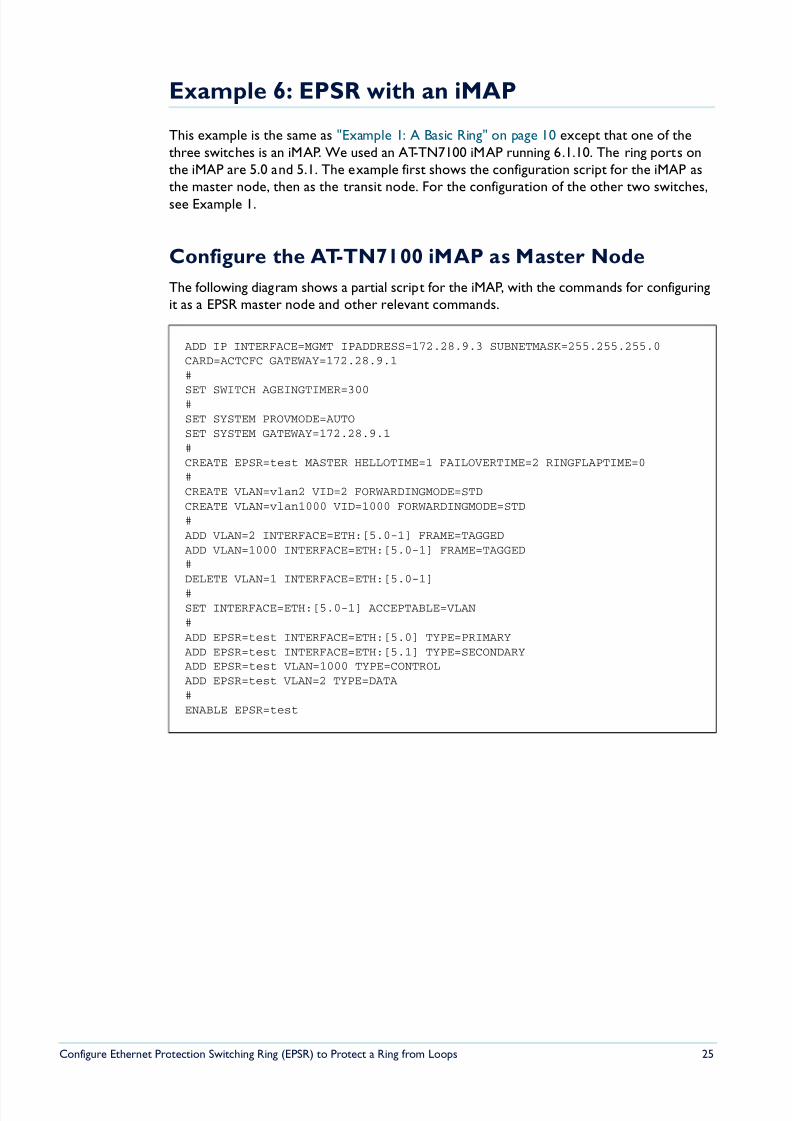
Example 6: EPSR with an iMAP
This example is the same as "Example 1: A Basic Ring" on page 10 except that one of thethree switches is an iMAP. We used an AT-TN7100 iMAP running 6.1.10. The ring ports onthe iMAP are 5.0 and 5.1. The example first shows the configuration script for the iMAP asthe master node, then as the transit node. For the configuration of the other two switches,see Example 1.
Configure the AT-TN7100 iMAP as Master Node
The following diagram shows a partial script for the iMAP, with the commands for configuringit as a EPSR master node and other relevant commands.
ADD IP INTERFACE=MGMT IPADDRESS=172.28.9.3 SUBNETMASK=255.255.255.0CARD=ACTCFC GATEWAY=172.28.9.1#
SET SWITCH AGEINGTIMER=300#SET SYSTEM PROVMODE=AUTOSET SYSTEM GATEWAY=172.28.9.1#CREATE EPSR=test MASTER HELLOTIME=1 FAILOVERTIME=2 RINGFLAPTIME=0#CREATE VLAN=vlan2 VID=2 FORWARDINGMODE=STDCREATE VLAN=vlan1000 VID=1000 FORWARDINGMODE=STD#ADD VLAN=2 INTERFACE=ETH:[5.0-1] FRAME=TAGGEDADD VLAN=1000 INTERFACE=ETH:[5.0-1] FRAME=TAGGED#DELETE VLAN=1 INTERFACE=ETH:[5.0-1]
#SET INTERFACE=ETH:[5.0-1] ACCEPTABLE=VLAN#ADD EPSR=test INTERFACE=ETH:[5.0] TYPE=PRIMARYADD EPSR=test INTERFACE=ETH:[5.1] TYPE=SECONDARYADD EPSR=test VLAN=1000 TYPE=CONTROLADD EPSR=test VLAN=2 TYPE=DATA#ENABLE EPSR=test
8/6/2019 Config Epsr Sd A
http://slidepdf.com/reader/full/config-epsr-sd-a 26/54
Configure Ethernet Protection Switching Ring (EPSR) to Protect a Ring from Loops 26
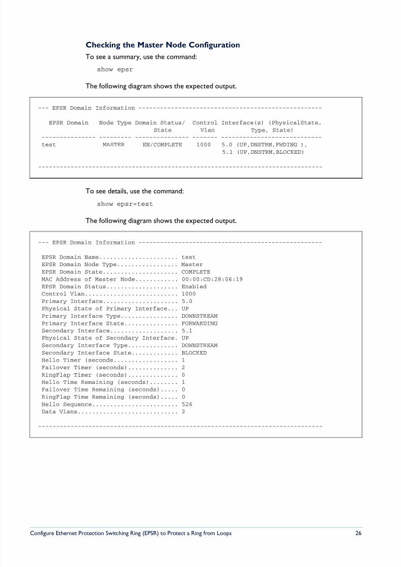
Checking the Master Node Configuration
To see a summary, use the command:
show epsr
The following diagram shows the expected output.
To see details, use the command:
show epsr=test
The following diagram shows the expected output.
--- EPSR Domain Information ---------------------------------------------------
EPSR Domain Node Type Domain Status/ Control Interface(s) (PhysicalState,State Vlan Type, State)
--------------- --------- --------------- ------- ----------------------------test MASTER EN/COMPLETE 1000 5.0 (UP,DNSTRM,FWDING ),
5.1 (UP,DNSTRM,BLOCKED)
-------------------------------------------------------------------------------
--- EPSR Domain Information ---------------------------------------------------
EPSR Domain Name...................... testEPSR Domain Node Type................. MasterEPSR Domain State..................... COMPLETEMAC Address of Master Node............ 00:00:CD:28:06:19EPSR Domain Status.................... EnabledControl Vlan.......................... 1000Primary Interface..................... 5.0Physical State of Primary Interface... UPPrimary Interface Type................ DOWNSTREAMPrimary Interface State............... FORWARDINGSecondary Interface................... 5.1Physical State of Secondary Interface. UPSecondary Interface Type.............. DOWNSTREAMSecondary Interface State............. BLOCKEDHello Timer (seconds.................. 1Failover Timer (seconds).............. 2RingFlap Timer (seconds).............. 0Hello Time Remaining (seconds)........ 1Failover Time Remaining (seconds)..... 0
RingFlap Time Remaining (seconds)..... 0Hello Sequence........................ 526Data Vlans............................ 2
-------------------------------------------------------------------------------
8/6/2019 Config Epsr Sd A
http://slidepdf.com/reader/full/config-epsr-sd-a 27/54
Configure Ethernet Protection Switching Ring (EPSR) to Protect a Ring from Loops 27
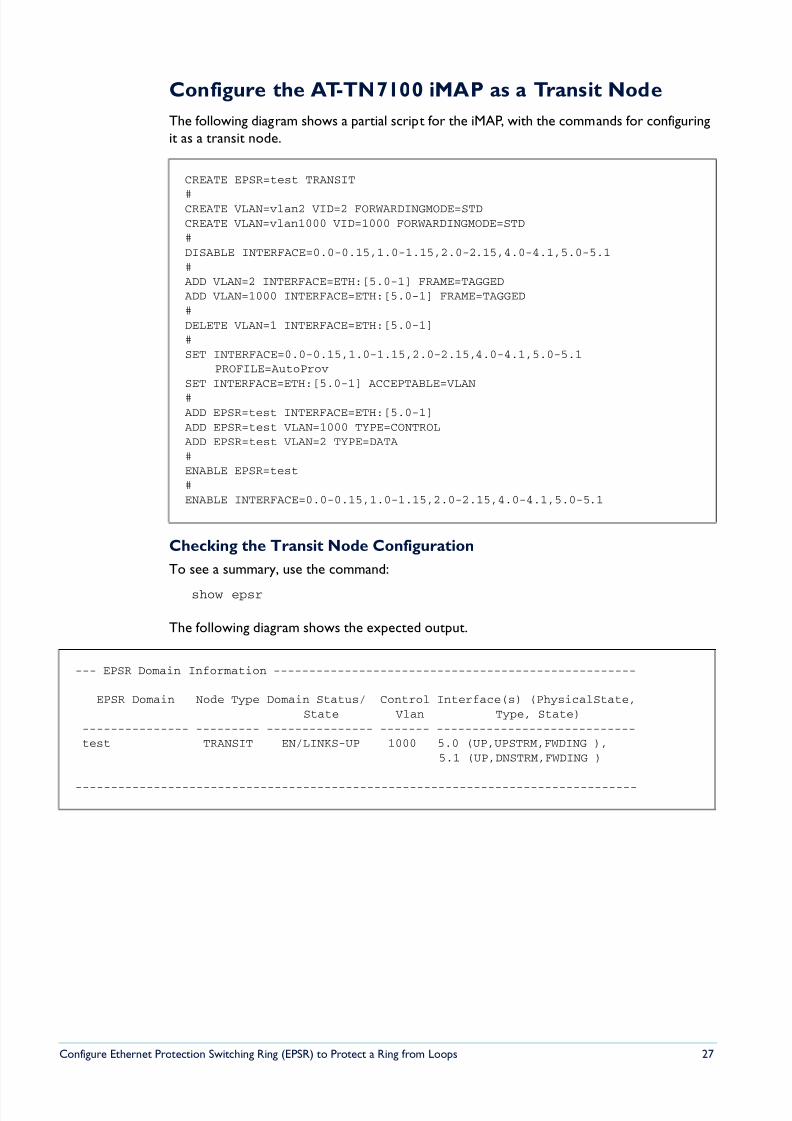
Configure the AT-TN7100 iMAP as a Transit Node
The following diagram shows a partial script for the iMAP, with the commands for configuringit as a transit node.
Checking the Transit Node Configuration
To see a summary, use the command:
show epsr
The following diagram shows the expected output.
CREATE EPSR=test TRANSIT
#CREATE VLAN=vlan2 VID=2 FORWARDINGMODE=STDCREATE VLAN=vlan1000 VID=1000 FORWARDINGMODE=STD#DISABLE INTERFACE=0.0-0.15,1.0-1.15,2.0-2.15,4.0-4.1,5.0-5.1#ADD VLAN=2 INTERFACE=ETH:[5.0-1] FRAME=TAGGEDADD VLAN=1000 INTERFACE=ETH:[5.0-1] FRAME=TAGGED#DELETE VLAN=1 INTERFACE=ETH:[5.0-1]#SET INTERFACE=0.0-0.15,1.0-1.15,2.0-2.15,4.0-4.1,5.0-5.1
PROFILE=AutoProvSET INTERFACE=ETH:[5.0-1] ACCEPTABLE=VLAN#ADD EPSR=test INTERFACE=ETH:[5.0-1]ADD EPSR=test VLAN=1000 TYPE=CONTROLADD EPSR=test VLAN=2 TYPE=DATA#ENABLE EPSR=test#ENABLE INTERFACE=0.0-0.15,1.0-1.15,2.0-2.15,4.0-4.1,5.0-5.1
--- EPSR Domain Information ---------------------------------------------------
EPSR Domain Node Type Domain Status/ Control Interface(s) (PhysicalState,State Vlan Type, State)
--------------- --------- --------------- ------- ----------------------------test TRANSIT EN/LINKS-UP 1000 5.0 (UP,UPSTRM,FWDING ),
5.1 (UP,DNSTRM,FWDING )
-------------------------------------------------------------------------------
8/6/2019 Config Epsr Sd A
http://slidepdf.com/reader/full/config-epsr-sd-a 28/54
Configure Ethernet Protection Switching Ring (EPSR) to Protect a Ring from Loops 28
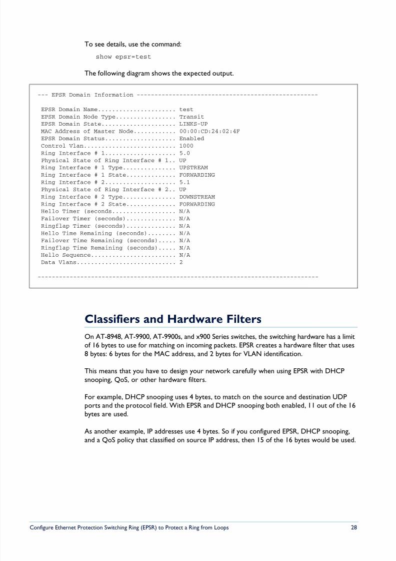
To see details, use the command:
show epsr=test
The following diagram shows the expected output.
Classifiers and Hardware Filters
On AT-8948, AT-9900, AT-9900s, and x900 Series switches, the switching hardware has a limitof 16 bytes to use for matching on incoming packets. EPSR creates a hardware filter that uses8 bytes: 6 bytes for the MAC address, and 2 bytes for VLAN identification.
This means that you have to design your network carefully when using EPSR with DHCPsnooping, QoS, or other hardware filters.
For example, DHCP snooping uses 4 bytes, to match on the source and destination UDPports and the protocol field. With EPSR and DHCP snooping both enabled, 11 out of the 16bytes are used.
As another example, IP addresses use 4 bytes. So if you configured EPSR, DHCP snooping,and a QoS policy that classified on source IP address, then 15 of the 16 bytes would be used.
--- EPSR Domain Information ---------------------------------------------------
EPSR Domain Name...................... testEPSR Domain Node Type................. TransitEPSR Domain State..................... LINKS-UPMAC Address of Master Node............ 00:00:CD:24:02:4FEPSR Domain Status.................... EnabledControl Vlan.......................... 1000Ring Interface # 1.................... 5.0Physical State of Ring Interface # 1.. UPRing Interface # 1 Type............... UPSTREAMRing Interface # 1 State.............. FORWARDINGRing Interface # 2.................... 5.1Physical State of Ring Interface # 2.. UP
Ring Interface # 2 Type............... DOWNSTREAMRing Interface # 2 State.............. FORWARDINGHello Timer (seconds.................. N/AFailover Timer (seconds).............. N/ARingflap Timer (seconds).............. N/AHello Time Remaining (seconds)........ N/AFailover Time Remaining (seconds)..... N/ARingflap Time Remaining (seconds)..... N/AHello Sequence........................ N/AData Vlans............................ 2
-------------------------------------------------------------------------------
8/6/2019 Config Epsr Sd A
http://slidepdf.com/reader/full/config-epsr-sd-a 29/54
Configure Ethernet Protection Switching Ring (EPSR) to Protect a Ring from Loops 29
Ports and Recovery Times
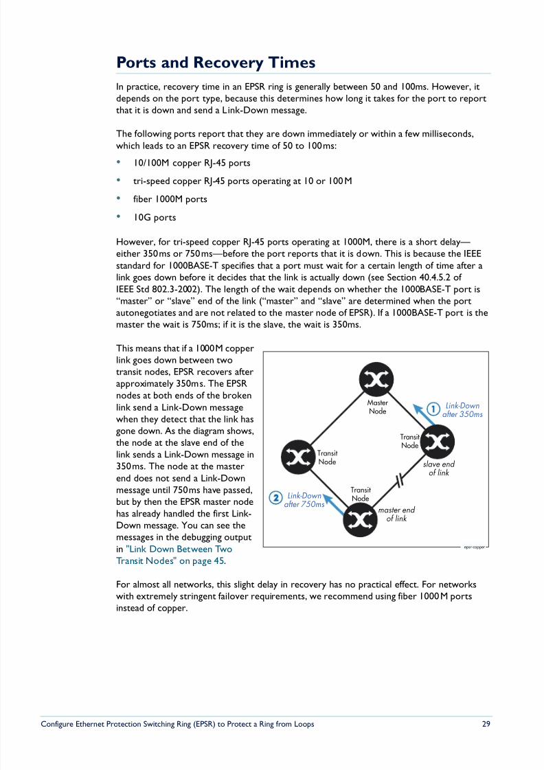
In practice, recovery time in an EPSR ring is generally between 50 and 100ms. However, itdepends on the port type, because this determines how long it takes for the port to reportthat it is down and send a Link-Down message.
The following ports report that they are down immediately or within a few milliseconds,which leads to an EPSR recovery time of 50 to 100ms:
• 10/100M copper RJ-45 ports
• tri-speed copper RJ-45 ports operating at 10 or 100M
• fiber 1000M ports
• 10G ports
However, for tri-speed copper RJ-45 ports operating at 1000M, there is a short delay— either 350ms or 750ms—before the port reports that it is down. This is because the IEEE
standard for 1000BASE-T specifies that a port must wait for a certain length of time after alink goes down before it decides that the link is actually down (see Section 40.4.5.2 of IEEE Std 802.3-2002). The length of the wait depends on whether the 1000BASE-T port is“master” or “slave” end of the link (“master” and “slave” are determined when the portautonegotiates and are not related to the master node of EPSR). If a 1000BASE-T port is themaster the wait is 750ms; if it is the slave, the wait is 350ms.
This means that if a 1000M copperlink goes down between twotransit nodes, EPSR recovers afterapproximately 350ms. The EPSRnodes at both ends of the broken
link send a Link-Down messagewhen they detect that the link hasgone down. As the diagram shows,the node at the slave end of thelink sends a Link-Down message in350ms. The node at the masterend does not send a Link-Downmessage until 750ms have passed,but by then the EPSR master nodehas already handled the first Link-Down message. You can see the
messages in the debugging outputin "Link Down Between TwoTransit Nodes" on page 45.
For almost all networks, this slight delay in recovery has no practical effect. For networkswith extremely stringent failover requirements, we recommend using fiber 1000M portsinstead of copper.
MasterNode
Transit Node
Transit Node
Transit Node
epsr-copper
slave end
of link
master end
of link
Link-Down
after 750ms
Link-Downafter 350ms
2
8/6/2019 Config Epsr Sd A
http://slidepdf.com/reader/full/config-epsr-sd-a 30/54
Configure Ethernet Protection Switching Ring (EPSR) to Protect a Ring from Loops 30
IGMP Snooping and Recovery Times
Since Software Version 281-03, IGMP snooping includes query solicitation, a new featurethat minimises loss of multicast data after a topology change.
When IGMP snooping is enabled on a VLAN, and EPSR changes the underlying link layer
topology of that VLAN, this can interrupt multicast data flow for a significant length of time.Query solicitation prevents this by monitoring the VLAN for any topology changes. When itdetects a change, it generates a special IGMP Leave message known as a Query Solicit, andfloods the Query Solicit message to all ports. When the IGMP Querier receives the message,it responds by sending a General Query. This refreshes snooped group membershipinformation in the network.
Query solicitation functions by default (without you enabling it) on the EPSR master node. Bydefault, the master node always sends a Query Solicit message when the topology changes.
On other switches in the network, the query solicitation is disabled by default, but you canenable it by using the command:
set igmpsnooping vlan={vlan-name|1..4094|all}querysolicit={on|yes|true}
If you enable query solicitation on an EPSR transit node, both that node and the master nodesend a Query Solicit message.
Once the Querier receives the Query Solicit message, it sends out a General Query andwaits for responses, which update the snooping information throughout the network. If necessary, you can reduce the time this takes by tuning the IGMP timers, especially thequeryresponseinterval parameter. For more information, see the “IGMP Timers andCounters” section of “How To Configure IGMP on Allied Telesyn Routers and Switches forMulticasting”. This How To Note is available in the Resource Center of the Documentationand Tools CDROM for Software Version 2.8.1, or from:www.alliedtelesyn.co.uk/en-gb/solutions/techdocs.asp?area=howto
Query solicitation also works with networks that use Spanning Tree (STP, RSTP, or MSTP).
Health Message Priority
EPSR uses Health messages to check that the ring is intact. If switches in the ring were to
drop Health messages, this could make the ring unstable. Therefore, Health messages aresent to the highest priority queue (queue 7), which uses strict priority scheduling by default.This makes sure that the switches forward Health messages even if the network is congested.
We recommend that you leave queue 7 as the highest priority queue, leave it using strictpriority scheduling, and only send essential control traffic to it.
In the unlikely event that this is impossible, you can increase the failover time so that themaster node only changes the ring topology if several Health messages in a row fail to arrive.By default, the failover time is set to two seconds, which means that the master node decidesthat the ring is down if two Health messages in a row fail to arrive.
8/6/2019 Config Epsr Sd A
http://slidepdf.com/reader/full/config-epsr-sd-a 31/54
Configure Ethernet Protection Switching Ring (EPSR) to Protect a Ring from Loops 31
EPSR State and Settings
To display the EPSR state, the attached VLANs, the ring ports, and the timer values, use thecommand:
show epsr
Master Nodein a Complete
Ring
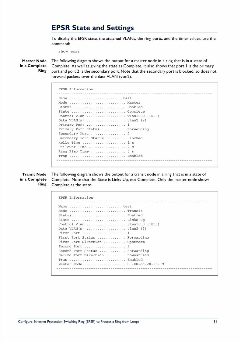
The following diagram shows the output for a master node in a ring that is in a state of Complete. As well as giving the state as Complete, it also shows that port 1 is the primaryport and port 2 is the secondary port. Note that the secondary port is blocked, so does notforward packets over the data VLAN (vlan2).
Transit Node
in a CompleteRing
The following diagram shows the output for a transit node in a ring that is in a state of
Complete. Note that the State is Links-Up, not Complete. Only the master node showsComplete as the state.
EPSR Information------------------------------------------------------------------------Name ........................ testMode .......................... MasterStatus ........................ EnabledState ......................... CompleteControl Vlan .................. vlan1000 (1000)
Data VLAN(s) .................. vlan2 (2)Primary Port .................. 1Primary Port Status ........... ForwardingSecondary Port ................ 2Secondary Port Status ......... BlockedHello Time .................... 1 sFailover Time ................. 2 sRing Flap Time ................ 0 sTrap .......................... Enabled
------------------------------------------------------------------------
EPSR Information------------------------------------------------------------------------Name ........................ testMode .......................... TransitStatus ........................ EnabledState ......................... Links-UpControl Vlan .................. vlan1000 (1000)Data VLAN(s) .................. vlan2 (2)First Port .................... 1First Port Status ............. ForwardingFirst Port Direction .......... UpstreamSecond Port ................... 2Second Port Status ............ ForwardingSecond Port Direction ......... DownstreamTrap .......................... EnabledMaster Node ................... 00-00-cd-28-06-19
------------------------------------------------------------------------
8/6/2019 Config Epsr Sd A
http://slidepdf.com/reader/full/config-epsr-sd-a 32/54
Configure Ethernet Protection Switching Ring (EPSR) to Protect a Ring from Loops 32
Master Node
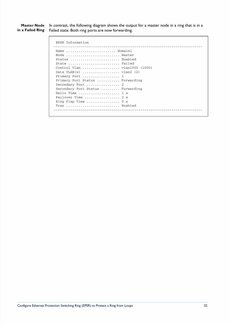
in a Failed Ring
In contrast, the following diagram shows the output for a master node in a ring that is in aFailed state. Both ring ports are now forwarding.
EPSR Information------------------------------------------------------------------------Name ........................ domain1Mode .......................... MasterStatus ........................ EnabledState ......................... FailedControl Vlan .................. vlan1000 (1000)Data VLAN(s) .................. vlan2 (2)Primary Port .................. 1Primary Port Status ........... ForwardingSecondary Port ................ 2Secondary Port Status ......... ForwardingHello Time .................... 1 sFailover Time ................. 2 sRing Flap Time ................ 0 sTrap .......................... Enabled
------------------------------------------------------------------------
8/6/2019 Config Epsr Sd A
http://slidepdf.com/reader/full/config-epsr-sd-a 33/54
Configure Ethernet Protection Switching Ring (EPSR) to Protect a Ring from Loops 33
SNMP Traps
You can use SNMP traps to notify you when events occur in the EPSR ring.
Download the latest version of the Allied Telesis Enterprise MIB fromwww.alliedtelesis.co.nz/support/updates/patches.html . The EPSR Group is contained in the
sub-file called atr-epsr.mib.
The EPSR Group has the object identifier prefix epsr ({ modules 136}), and contains acollection of objects and traps for monitoring EPSR states.
The following trap is defined under the epsrEvents ({ epsr 0}) subtree:
• atrEpsrNodeTrap ({ epsrEvents 1}) is the trap type of the EPSR node trap (master/transit).
The following objects are defined under the epsrEventVariables ({ epsr 1}) subtree:
• atrEpsrNodeTrapType ({epsrEventVariables 1}) is the trap type of the EPSR node trap
(master/transit).• atrEpsrDomainName ({epsrEventVariables 2}) is the name assigned to the EPSR domain.
• atrEpsrFromState ({epsrEventVariables 3}) is the defined state that an EPSR domain is
transitioning from.
• atrEpsrToState ({epsrEventVariables 4}) is the state that an EPSR domain is transitioning
to.
• atrEpsrControlVLANId ({epsrEventVariables 5}) is the VLAN identifier for the control
VLAN.
• atrEpsrPrimaryIfIndex ({epsrEventVariables 6}) is the ifIndex of the primary interface.
• atrEpsrPrimaryIfState ({epsrEventVariables 7}) is the current state of the primary
interface.
• atrEpsrSecondaryIfIndex ({epsrEventVariables 8}) is the ifIndex of the secondary
interface.
• atrEpsrSecondaryIfState ({epsrEventVariables 9}) is the current state of the secondary
interface.
8/6/2019 Config Epsr Sd A
http://slidepdf.com/reader/full/config-epsr-sd-a 34/54
Configure Ethernet Protection Switching Ring (EPSR) to Protect a Ring from Loops 34
Counters
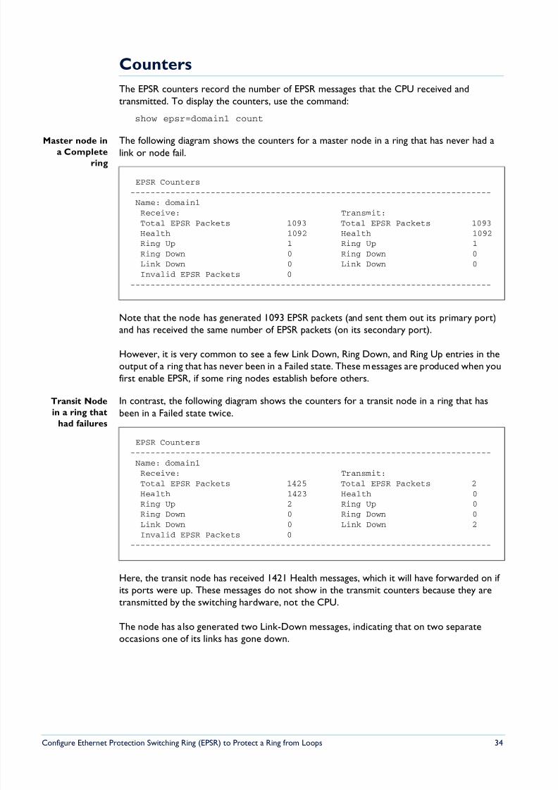
The EPSR counters record the number of EPSR messages that the CPU received andtransmitted. To display the counters, use the command:
show epsr=domain1 count
Master node ina Complete
ring
The following diagram shows the counters for a master node in a ring that has never had alink or node fail.
Note that the node has generated 1093 EPSR packets (and sent them out its primary port)and has received the same number of EPSR packets (on its secondary port).
However, it is very common to see a few Link Down, Ring Down, and Ring Up entries in theoutput of a ring that has never been in a Failed state. These messages are produced when youfirst enable EPSR, if some ring nodes establish before others.
Transit Node
in a ring thathad failures
In contrast, the following diagram shows the counters for a transit node in a ring that has
been in a Failed state twice.
Here, the transit node has received 1421 Health messages, which it will have forwarded on if its ports were up. These messages do not show in the transmit counters because they aretransmitted by the switching hardware, not the CPU.
The node has also generated two Link-Down messages, indicating that on two separateoccasions one of its links has gone down.
EPSR Counters------------------------------------------------------------------------Name: domain1Receive: Transmit:Total EPSR Packets 1093 Total EPSR Packets 1093Health 1092 Health 1092Ring Up 1 Ring Up 1Ring Down 0 Ring Down 0Link Down 0 Link Down 0
Invalid EPSR Packets 0------------------------------------------------------------------------
EPSR Counters------------------------------------------------------------------------Name: domain1Receive: Transmit:Total EPSR Packets 1425 Total EPSR Packets 2Health 1423 Health 0Ring Up 2 Ring Up 0Ring Down 0 Ring Down 0Link Down 0 Link Down 2Invalid EPSR Packets 0
------------------------------------------------------------------------
8/6/2019 Config Epsr Sd A
http://slidepdf.com/reader/full/config-epsr-sd-a 35/54
Configure Ethernet Protection Switching Ring (EPSR) to Protect a Ring from Loops 35
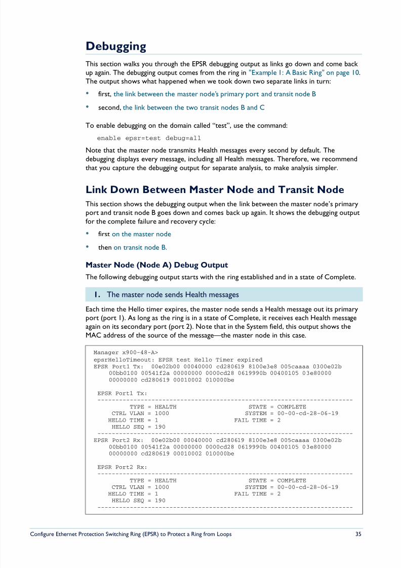
Debugging
This section walks you through the EPSR debugging output as links go down and come back up again. The debugging output comes from the ring in "Example 1: A Basic Ring" on page 10.The output shows what happened when we took down two separate links in turn:
• first, the link between the master node’s primary port and transit node B
• second, the link between the two transit nodes B and C
To enable debugging on the domain called “test”, use the command:
enable epsr=test debug=all
Note that the master node transmits Health messages every second by default. Thedebugging displays every message, including all Health messages. Therefore, we recommendthat you capture the debugging output for separate analysis, to make analysis simpler.
Link Down Between Master Node and Transit Node
This section shows the debugging output when the link between the master node’s primaryport and transit node B goes down and comes back up again. It shows the debugging outputfor the complete failure and recovery cycle:
• first on the master node
• then on transit node B.
Master Node (Node A) Debug Output
The following debugging output starts with the ring established and in a state of Complete.
Each time the Hello timer expires, the master node sends a Health message out its primaryport (port 1). As long as the ring is in a state of Complete, it receives each Health messageagain on its secondary port (port 2). Note that in the System field, this output shows theMAC address of the source of the message—the master node in this case.
1. The master node sends Health messages
Manager x900-48-A>epsrHelloTimeout: EPSR test Hello Timer expiredEPSR Port1 Tx: 00e02b00 00040000 cd280619 8100e3e8 005caaaa 0300e02b
00bb0100 00541f2a 00000000 0000cd28 0619990b 00400105 03e8000000000000 cd280619 00010002 010000be
EPSR Port1 Tx:
-----------------------------------------------------------------------TYPE = HEALTH STATE = COMPLETE
CTRL VLAN = 1000 SYSTEM = 00-00-cd-28-06-19HELLO TIME = 1 FAIL TIME = 2HELLO SEQ = 190
-----------------------------------------------------------------------EPSR Port2 Rx: 00e02b00 00040000 cd280619 8100e3e8 005caaaa 0300e02b
00bb0100 00541f2a 00000000 0000cd28 0619990b 00400105 03e8000000000000 cd280619 00010002 010000be
EPSR Port2 Rx:-----------------------------------------------------------------------
TYPE = HEALTH STATE = COMPLETECTRL VLAN = 1000 SYSTEM = 00-00-cd-28-06-19
HELLO TIME = 1 FAIL TIME = 2HELLO SEQ = 190
-----------------------------------------------------------------------
8/6/2019 Config Epsr Sd A
http://slidepdf.com/reader/full/config-epsr-sd-a 36/54
Configure Ethernet Protection Switching Ring (EPSR) to Protect a Ring from Loops 36
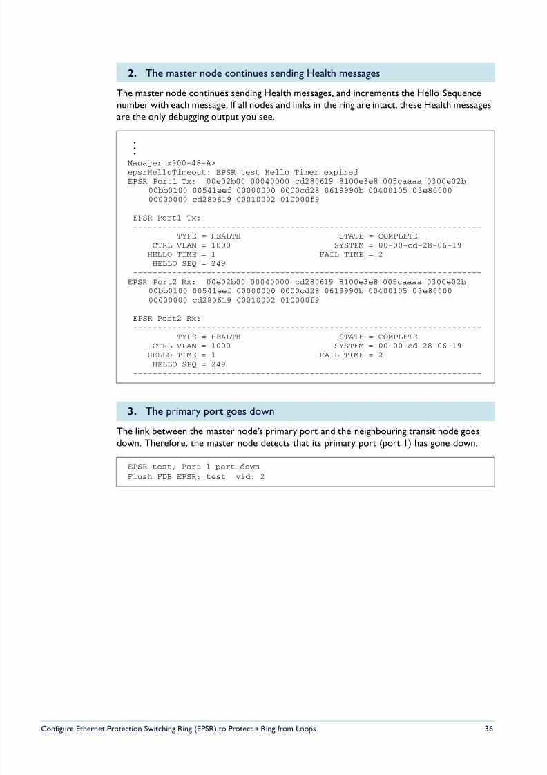
The master node continues sending Health messages, and increments the Hello Sequencenumber with each message. If all nodes and links in the ring are intact, these Health messagesare the only debugging output you see.
The link between the master node’s primary port and the neighbouring transit node goesdown. Therefore, the master node detects that its primary port (port 1) has gone down.
2. The master node continues sending Health messages
.
.
.Manager x900-48-A>epsrHelloTimeout: EPSR test Hello Timer expiredEPSR Port1 Tx: 00e02b00 00040000 cd280619 8100e3e8 005caaaa 0300e02b
00bb0100 00541eef 00000000 0000cd28 0619990b 00400105 03e8000000000000 cd280619 00010002 010000f9
EPSR Port1 Tx:-----------------------------------------------------------------------
TYPE = HEALTH STATE = COMPLETECTRL VLAN = 1000 SYSTEM = 00-00-cd-28-06-19
HELLO TIME = 1 FAIL TIME = 2HELLO SEQ = 249
-----------------------------------------------------------------------EPSR Port2 Rx: 00e02b00 00040000 cd280619 8100e3e8 005caaaa 0300e02b
00bb0100 00541eef 00000000 0000cd28 0619990b 00400105 03e8000000000000 cd280619 00010002 010000f9
EPSR Port2 Rx:-----------------------------------------------------------------------
TYPE = HEALTH STATE = COMPLETECTRL VLAN = 1000 SYSTEM = 00-00-cd-28-06-19
HELLO TIME = 1 FAIL TIME = 2HELLO SEQ = 249
-----------------------------------------------------------------------
3. The primary port goes down
EPSR test, Port 1 port downFlush FDB EPSR: test vid: 2
8/6/2019 Config Epsr Sd A
http://slidepdf.com/reader/full/config-epsr-sd-a 37/54
Configure Ethernet Protection Switching Ring (EPSR) to Protect a Ring from Loops 37
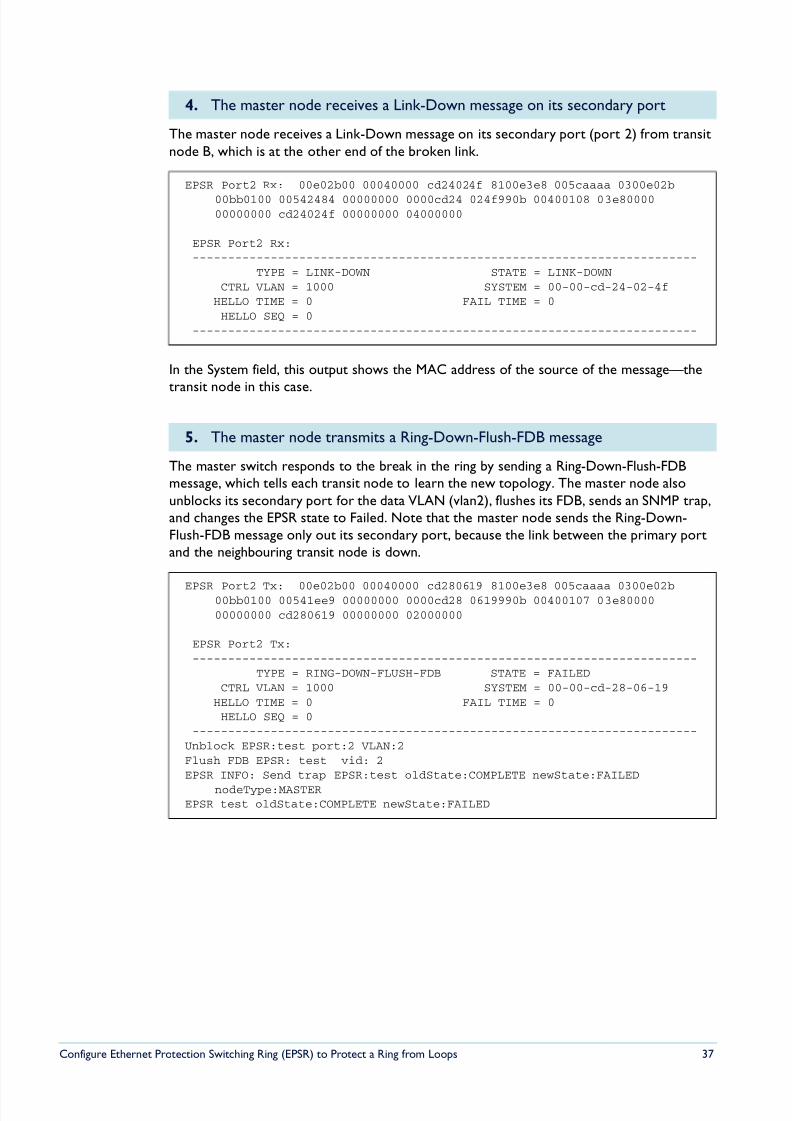
The master node receives a Link-Down message on its secondary port (port 2) from transitnode B, which is at the other end of the broken link.
In the System field, this output shows the MAC address of the source of the message—the
transit node in this case.
The master switch responds to the break in the ring by sending a Ring-Down-Flush-FDBmessage, which tells each transit node to learn the new topology. The master node alsounblocks its secondary port for the data VLAN (vlan2), flushes its FDB, sends an SNMP trap,and changes the EPSR state to Failed. Note that the master node sends the Ring-Down-Flush-FDB message only out its secondary port, because the link between the primary portand the neighbouring transit node is down.
4. The master node receives a Link-Down message on its secondary port
EPSR Port2 Rx: 00e02b00 00040000 cd24024f 8100e3e8 005caaaa 0300e02b
00bb0100 00542484 00000000 0000cd24 024f990b 00400108 03e8000000000000 cd24024f 00000000 04000000
EPSR Port2 Rx:-----------------------------------------------------------------------
TYPE = LINK-DOWN STATE = LINK-DOWNCTRL VLAN = 1000 SYSTEM = 00-00-cd-24-02-4f
HELLO TIME = 0 FAIL TIME = 0HELLO SEQ = 0
-----------------------------------------------------------------------
5. The master node transmits a Ring-Down-Flush-FDB message
EPSR Port2 Tx: 00e02b00 00040000 cd280619 8100e3e8 005caaaa 0300e02b00bb0100 00541ee9 00000000 0000cd28 0619990b 00400107 03e8000000000000 cd280619 00000000 02000000
EPSR Port2 Tx:-----------------------------------------------------------------------
TYPE = RING-DOWN-FLUSH-FDB STATE = FAILEDCTRL VLAN = 1000 SYSTEM = 00-00-cd-28-06-19
HELLO TIME = 0 FAIL TIME = 0HELLO SEQ = 0
-----------------------------------------------------------------------Unblock EPSR:test port:2 VLAN:2Flush FDB EPSR: test vid: 2EPSR INFO: Send trap EPSR:test oldState:COMPLETE newState:FAILED
nodeType:MASTEREPSR test oldState:COMPLETE newState:FAILED
8/6/2019 Config Epsr Sd A
http://slidepdf.com/reader/full/config-epsr-sd-a 38/54
Configure Ethernet Protection Switching Ring (EPSR) to Protect a Ring from Loops 38
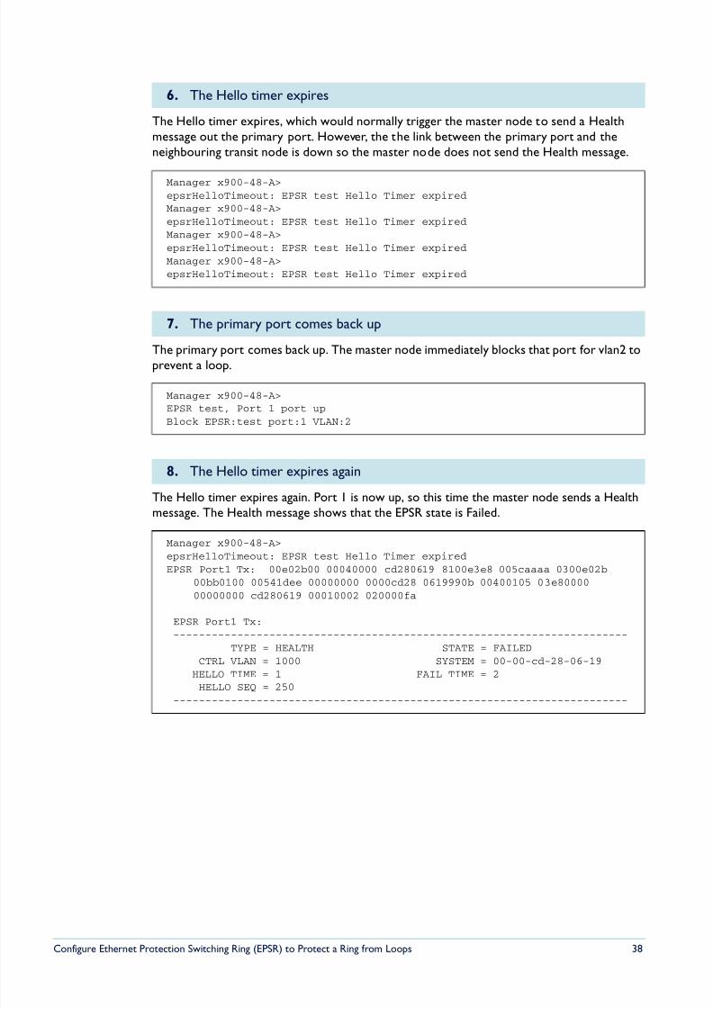
The Hello timer expires, which would normally trigger the master node to send a Healthmessage out the primary port. However, the the link between the primary port and theneighbouring transit node is down so the master node does not send the Health message.
The primary port comes back up. The master node immediately blocks that port for vlan2 toprevent a loop.
The Hello timer expires again. Port 1 is now up, so this time the master node sends a Healthmessage. The Health message shows that the EPSR state is Failed.
6. The Hello timer expires
Manager x900-48-A>epsrHelloTimeout: EPSR test Hello Timer expiredManager x900-48-A>epsrHelloTimeout: EPSR test Hello Timer expiredManager x900-48-A>epsrHelloTimeout: EPSR test Hello Timer expiredManager x900-48-A>epsrHelloTimeout: EPSR test Hello Timer expired
7. The primary port comes back up
Manager x900-48-A>EPSR test, Port 1 port upBlock EPSR:test port:1 VLAN:2
8. The Hello timer expires again
Manager x900-48-A>epsrHelloTimeout: EPSR test Hello Timer expiredEPSR Port1 Tx: 00e02b00 00040000 cd280619 8100e3e8 005caaaa 0300e02b
00bb0100 00541dee 00000000 0000cd28 0619990b 00400105 03e8000000000000 cd280619 00010002 020000fa
EPSR Port1 Tx:-----------------------------------------------------------------------
TYPE = HEALTH STATE = FAILEDCTRL VLAN = 1000 SYSTEM = 00-00-cd-28-06-19
HELLO TIME = 1 FAIL TIME = 2HELLO SEQ = 250
-----------------------------------------------------------------------
8/6/2019 Config Epsr Sd A
http://slidepdf.com/reader/full/config-epsr-sd-a 39/54
Configure Ethernet Protection Switching Ring (EPSR) to Protect a Ring from Loops 39
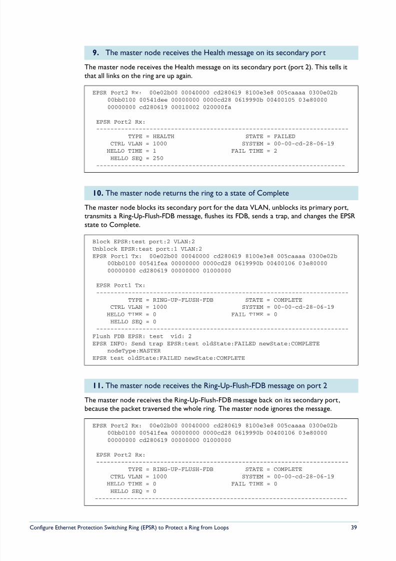
The master node receives the Health message on its secondary port (port 2). This tells itthat all links on the ring are up again.
The master node blocks its secondary port for the data VLAN, unblocks its primary port,transmits a Ring-Up-Flush-FDB message, flushes its FDB, sends a trap, and changes the EPSRstate to Complete.
The master node receives the Ring-Up-Flush-FDB message back on its secondary port,because the packet traversed the whole ring. The master node ignores the message.
9. The master node receives the Health message on its secondary port
EPSR Port2 Rx: 00e02b00 00040000 cd280619 8100e3e8 005caaaa 0300e02b
00bb0100 00541dee 00000000 0000cd28 0619990b 00400105 03e8000000000000 cd280619 00010002 020000fa
EPSR Port2 Rx:-----------------------------------------------------------------------
TYPE = HEALTH STATE = FAILEDCTRL VLAN = 1000 SYSTEM = 00-00-cd-28-06-19
HELLO TIME = 1 FAIL TIME = 2HELLO SEQ = 250
----------------------------------------------------------------------
10. The master node returns the ring to a state of Complete
Block EPSR:test port:2 VLAN:2Unblock EPSR:test port:1 VLAN:2EPSR Port1 Tx: 00e02b00 00040000 cd280619 8100e3e8 005caaaa 0300e02b
00bb0100 00541fea 00000000 0000cd28 0619990b 00400106 03e8000000000000 cd280619 00000000 01000000
EPSR Port1 Tx:
-----------------------------------------------------------------------TYPE = RING-UP-FLUSH-FDB STATE = COMPLETECTRL VLAN = 1000 SYSTEM = 00-00-cd-28-06-19
HELLO TIME = 0 FAIL TIME = 0HELLO SEQ = 0
-----------------------------------------------------------------------Flush FDB EPSR: test vid: 2EPSR INFO: Send trap EPSR:test oldState:FAILED newState:COMPLETE
nodeType:MASTEREPSR test oldState:FAILED newState:COMPLETE
11. The master node receives the Ring-Up-Flush-FDB message on port 2
EPSR Port2 Rx: 00e02b00 00040000 cd280619 8100e3e8 005caaaa 0300e02b00bb0100 00541fea 00000000 0000cd28 0619990b 00400106 03e8000000000000 cd280619 00000000 01000000
EPSR Port2 Rx:-----------------------------------------------------------------------
TYPE = RING-UP-FLUSH-FDB STATE = COMPLETECTRL VLAN = 1000 SYSTEM = 00-00-cd-28-06-19
HELLO TIME = 0 FAIL TIME = 0
HELLO SEQ = 0-----------------------------------------------------------------------
8/6/2019 Config Epsr Sd A
http://slidepdf.com/reader/full/config-epsr-sd-a 40/54
Configure Ethernet Protection Switching Ring (EPSR) to Protect a Ring from Loops 40
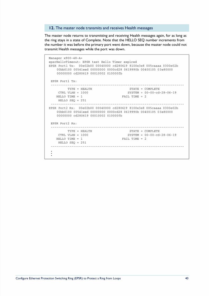
The master node returns to transmitting and receiving Health messages again, for as long asthe ring stays in a state of Complete. Note that the HELLO SEQ number increments fromthe number it was before the primary port went down, because the master node could nottransmit Health messages while the port was down.
12. The master node transmits and receives Health messages
Manager x900-48-A>epsrHelloTimeout: EPSR test Hello Timer expiredEPSR Port1 Tx: 00e02b00 00040000 cd280619 8100e3e8 005caaaa 0300e02b
00bb0100 00541eed 00000000 0000cd28 0619990b 00400105 03e8000000000000 cd280619 00010002 010000fb
EPSR Port1 Tx:-----------------------------------------------------------------------
TYPE = HEALTH STATE = COMPLETECTRL VLAN = 1000 SYSTEM = 00-00-cd-28-06-19
HELLO TIME = 1 FAIL TIME = 2HELLO SEQ = 251
-----------------------------------------------------------------------EPSR Port2 Rx: 00e02b00 00040000 cd280619 8100e3e8 005caaaa 0300e02b
00bb0100 00541eed 00000000 0000cd28 0619990b 00400105 03e8000000000000 cd280619 00010002 010000fb
EPSR Port2 Rx:-----------------------------------------------------------------------
TYPE = HEALTH STATE = COMPLETECTRL VLAN = 1000 SYSTEM = 00-00-cd-28-06-19
HELLO TIME = 1 FAIL TIME = 2HELLO SEQ = 251
-----------------------------------------------------------------------
.
.
.
8/6/2019 Config Epsr Sd A
http://slidepdf.com/reader/full/config-epsr-sd-a 41/54
Configure Ethernet Protection Switching Ring (EPSR) to Protect a Ring from Loops 41
Transit Node (Node B) Debug Output
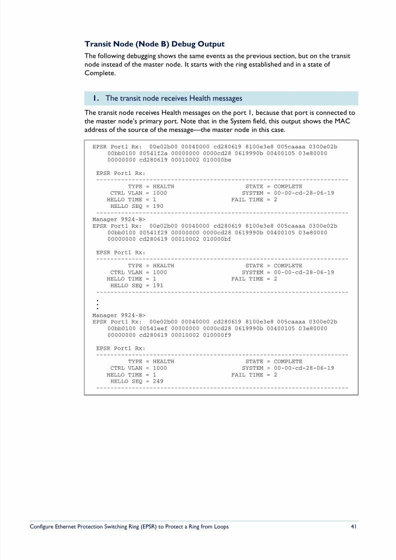
The following debugging shows the same events as the previous section, but on the transitnode instead of the master node. It starts with the ring established and in a state of Complete.
The transit node receives Health messages on the port 1, because that port is connected tothe master node’s primary port. Note that in the System field, this output shows the MACaddress of the source of the message—the master node in this case.
1. The transit node receives Health messages
EPSR Port1 Rx: 00e02b00 00040000 cd280619 8100e3e8 005caaaa 0300e02b00bb0100 00541f2a 00000000 0000cd28 0619990b 00400105 03e8000000000000 cd280619 00010002 010000be
EPSR Port1 Rx:-----------------------------------------------------------------------
TYPE = HEALTH STATE = COMPLETECTRL VLAN = 1000 SYSTEM = 00-00-cd-28-06-19
HELLO TIME = 1 FAIL TIME = 2HELLO SEQ = 190
-----------------------------------------------------------------------Manager 9924-B>EPSR Port1 Rx: 00e02b00 00040000 cd280619 8100e3e8 005caaaa 0300e02b
00bb0100 00541f29 00000000 0000cd28 0619990b 00400105 03e8000000000000 cd280619 00010002 010000bf
EPSR Port1 Rx:-----------------------------------------------------------------------
TYPE = HEALTH STATE = COMPLETECTRL VLAN = 1000 SYSTEM = 00-00-cd-28-06-19
HELLO TIME = 1 FAIL TIME = 2HELLO SEQ = 191
-----------------------------------------------------------------------...
Manager 9924-B>EPSR Port1 Rx: 00e02b00 00040000 cd280619 8100e3e8 005caaaa 0300e02b
00bb0100 00541eef 00000000 0000cd28 0619990b 00400105 03e8000000000000 cd280619 00010002 010000f9
EPSR Port1 Rx:-----------------------------------------------------------------------
TYPE = HEALTH STATE = COMPLETECTRL VLAN = 1000 SYSTEM = 00-00-cd-28-06-19
HELLO TIME = 1 FAIL TIME = 2HELLO SEQ = 249
-----------------------------------------------------------------------
8/6/2019 Config Epsr Sd A
http://slidepdf.com/reader/full/config-epsr-sd-a 42/54
Configure Ethernet Protection Switching Ring (EPSR) to Protect a Ring from Loops 42
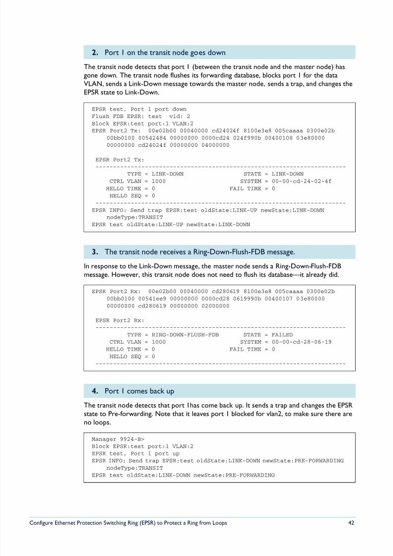
The transit node detects that port 1 (between the transit node and the master node) hasgone down. The transit node flushes its forwarding database, blocks port 1 for the dataVLAN, sends a Link-Down message towards the master node, sends a trap, and changes theEPSR state to Link-Down.
In response to the Link-Down message, the master node sends a Ring-Down-Flush-FDBmessage. However, this transit node does not need to flush its database—it already did.
The transit node detects that port 1has come back up. It sends a trap and changes the EPSRstate to Pre-forwarding. Note that it leaves port 1 blocked for vlan2, to make sure there areno loops.
2. Port 1 on the transit node goes down
EPSR test, Port 1 port downFlush FDB EPSR: test vid: 2Block EPSR:test port:1 VLAN:2EPSR Port2 Tx: 00e02b00 00040000 cd24024f 8100e3e8 005caaaa 0300e02b
00bb0100 00542484 00000000 0000cd24 024f990b 00400108 03e8000000000000 cd24024f 00000000 04000000
EPSR Port2 Tx:-----------------------------------------------------------------------
TYPE = LINK-DOWN STATE = LINK-DOWNCTRL VLAN = 1000 SYSTEM = 00-00-cd-24-02-4f
HELLO TIME = 0 FAIL TIME = 0
HELLO SEQ = 0-----------------------------------------------------------------------
EPSR INFO: Send trap EPSR:test oldState:LINK-UP newState:LINK-DOWNnodeType:TRANSIT
EPSR test oldState:LINK-UP newState:LINK-DOWN
3. The transit node receives a Ring-Down-Flush-FDB message.
EPSR Port2 Rx: 00e02b00 00040000 cd280619 8100e3e8 005caaaa 0300e02b00bb0100 00541ee9 00000000 0000cd28 0619990b 00400107 03e8000000000000 cd280619 00000000 02000000
EPSR Port2 Rx:-----------------------------------------------------------------------
TYPE = RING-DOWN-FLUSH-FDB STATE = FAILEDCTRL VLAN = 1000 SYSTEM = 00-00-cd-28-06-19
HELLO TIME = 0 FAIL TIME = 0HELLO SEQ = 0
-----------------------------------------------------------------------
4. Port 1 comes back up
Manager 9924-B>Block EPSR:test port:1 VLAN:2EPSR test, Port 1 port upEPSR INFO: Send trap EPSR:test oldState:LINK-DOWN newState:PRE-FORWARDING
nodeType:TRANSITEPSR test oldState:LINK-DOWN newState:PRE-FORWARDING
8/6/2019 Config Epsr Sd A
http://slidepdf.com/reader/full/config-epsr-sd-a 43/54
Configure Ethernet Protection Switching Ring (EPSR) to Protect a Ring from Loops 43
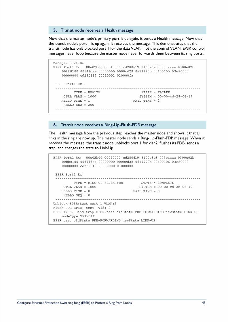
Now that the master node’s primary port is up again, it sends a Health message. Now thatthe transit node’s port 1 is up again, it receives the message. This demonstrates that thetransit node has only blocked port 1 for the data VLAN, not the control VLAN. EPSR controlmessages never loop because the master node never forwards them between its ring ports.
The Health message from the previous step reaches the master node and shows it that alllinks in the ring are now up. The master node sends a Ring-Up-Flush-FDB message. When itreceives the message, the transit node unblocks port 1 for vlan2, flushes its FDB, sends atrap, and changes the state to Link-Up.
5. Transit node receives a Health message
Manager 9924-B>EPSR Port1 Rx: 00e02b00 00040000 cd280619 8100e3e8 005caaaa 0300e02b
00bb0100 00541dee 00000000 0000cd28 0619990b 00400105 03e8000000000000 cd280619 00010002 020000fa
EPSR Port1 Rx:-----------------------------------------------------------------------
TYPE = HEALTH STATE = FAILEDCTRL VLAN = 1000 SYSTEM = 00-00-cd-28-06-19
HELLO TIME = 1 FAIL TIME = 2HELLO SEQ = 250
-----------------------------------------------------------------------
6. Transit node receives a Ring-Up-Flush-FDB message.
EPSR Port1 Rx: 00e02b00 00040000 cd280619 8100e3e8 005caaaa 0300e02b00bb0100 00541fea 00000000 0000cd28 0619990b 00400106 03e8000000000000 cd280619 00000000 01000000
EPSR Port1 Rx:-----------------------------------------------------------------------
TYPE = RING-UP-FLUSH-FDB STATE = COMPLETECTRL VLAN = 1000 SYSTEM = 00-00-cd-28-06-19
HELLO TIME = 0 FAIL TIME = 0HELLO SEQ = 0
-----------------------------------------------------------------------Unblock EPSR:test port:1 VLAN:2Flush FDB EPSR: test vid: 2EPSR INFO: Send trap EPSR:test oldState:PRE-FORWARDING newState:LINK-UP
nodeType:TRANSITEPSR test oldState:PRE-FORWARDING newState:LINK-UP
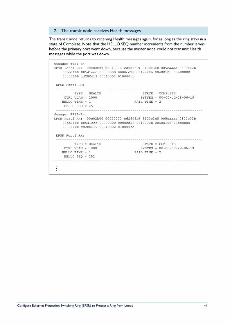
8/6/2019 Config Epsr Sd A
http://slidepdf.com/reader/full/config-epsr-sd-a 44/54
Configure Ethernet Protection Switching Ring (EPSR) to Protect a Ring from Loops 44
The transit node returns to receiving Health messages again, for as long as the ring stays in astate of Complete. Note that the HELLO SEQ number increments from the number it wasbefore the primary port went down, because the master node could not transmit Healthmessages while the port was down.
7. The transit node receives Health messages
Manager 9924-B>EPSR Port1 Rx: 00e02b00 00040000 cd280619 8100e3e8 005caaaa 0300e02b
00bb0100 00541eed 00000000 0000cd28 0619990b 00400105 03e8000000000000 cd280619 00010002 010000fb
EPSR Port1 Rx:-----------------------------------------------------------------------
TYPE = HEALTH STATE = COMPLETECTRL VLAN = 1000 SYSTEM = 00-00-cd-28-06-19
HELLO TIME = 1 FAIL TIME = 2HELLO SEQ = 251
-----------------------------------------------------------------------
Manager 9924-B>EPSR Port1 Rx: 00e02b00 00040000 cd280619 8100e3e8 005caaaa 0300e02b
00bb0100 00541eec 00000000 0000cd28 0619990b 00400105 03e8000000000000 cd280619 00010002 010000fc
EPSR Port1 Rx:-----------------------------------------------------------------------
TYPE = HEALTH STATE = COMPLETECTRL VLAN = 1000 SYSTEM = 00-00-cd-28-06-19
HELLO TIME = 1 FAIL TIME = 2HELLO SEQ = 252
-----------------------------------------------------------------------
.
.
.
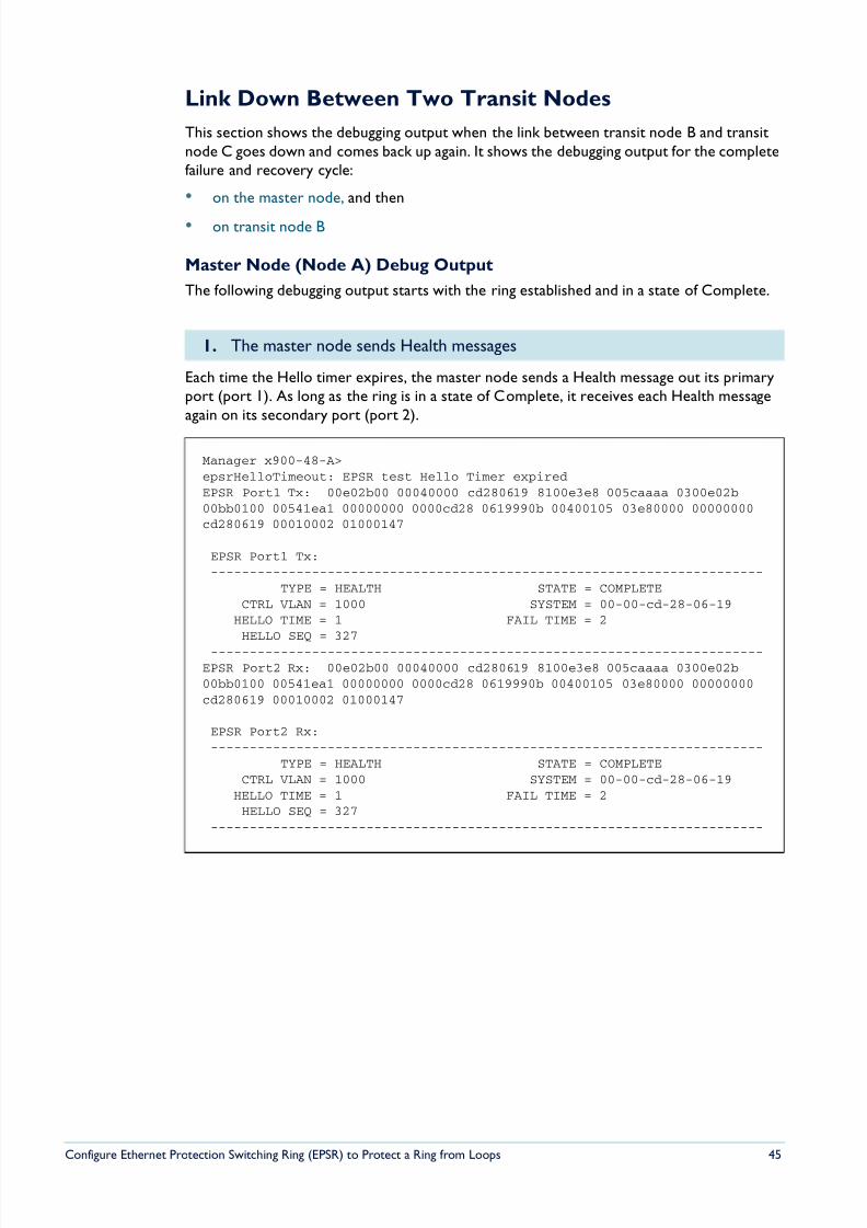
8/6/2019 Config Epsr Sd A
http://slidepdf.com/reader/full/config-epsr-sd-a 45/54
Configure Ethernet Protection Switching Ring (EPSR) to Protect a Ring from Loops 45
Link Down Between Two Transit Nodes
This section shows the debugging output when the link between transit node B and transitnode C goes down and comes back up again. It shows the debugging output for the completefailure and recovery cycle:
• on the master node, and then
• on transit node B
Master Node (Node A) Debug Output
The following debugging output starts with the ring established and in a state of Complete.
Each time the Hello timer expires, the master node sends a Health message out its primaryport (port 1). As long as the ring is in a state of Complete, it receives each Health messageagain on its secondary port (port 2).
1. The master node sends Health messages
Manager x900-48-A>epsrHelloTimeout: EPSR test Hello Timer expiredEPSR Port1 Tx: 00e02b00 00040000 cd280619 8100e3e8 005caaaa 0300e02b00bb0100 00541ea1 00000000 0000cd28 0619990b 00400105 03e80000 00000000cd280619 00010002 01000147
EPSR Port1 Tx:-----------------------------------------------------------------------
TYPE = HEALTH STATE = COMPLETECTRL VLAN = 1000 SYSTEM = 00-00-cd-28-06-19
HELLO TIME = 1 FAIL TIME = 2HELLO SEQ = 327
-----------------------------------------------------------------------EPSR Port2 Rx: 00e02b00 00040000 cd280619 8100e3e8 005caaaa 0300e02b00bb0100 00541ea1 00000000 0000cd28 0619990b 00400105 03e80000 00000000cd280619 00010002 01000147
EPSR Port2 Rx:-----------------------------------------------------------------------
TYPE = HEALTH STATE = COMPLETECTRL VLAN = 1000 SYSTEM = 00-00-cd-28-06-19
HELLO TIME = 1 FAIL TIME = 2HELLO SEQ = 327
-----------------------------------------------------------------------
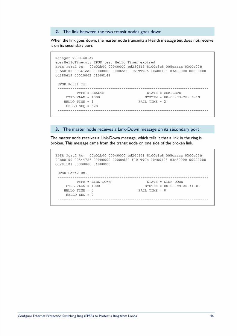
8/6/2019 Config Epsr Sd A
http://slidepdf.com/reader/full/config-epsr-sd-a 46/54
Configure Ethernet Protection Switching Ring (EPSR) to Protect a Ring from Loops 46
When the link goes down, the master node transmits a Health message but does not receiveit on its secondary port.
The master node receives a Link-Down message, which tells it that a link in the ring isbroken. This message came from the transit node on one side of the broken link.
2. The link between the two transit nodes goes down
Manager x900-48-A>epsrHelloTimeout: EPSR test Hello Timer expiredEPSR Port1 Tx: 00e02b00 00040000 cd280619 8100e3e8 005caaaa 0300e02b00bb0100 00541ea0 00000000 0000cd28 0619990b 00400105 03e80000 00000000cd280619 00010002 01000148
EPSR Port1 Tx:-----------------------------------------------------------------------
TYPE = HEALTH STATE = COMPLETECTRL VLAN = 1000 SYSTEM = 00-00-cd-28-06-19
HELLO TIME = 1 FAIL TIME = 2HELLO SEQ = 328
-----------------------------------------------------------------------
3. The master node receives a Link-Down message on its secondary port
EPSR Port2 Rx: 00e02b00 00040000 cd20f101 8100e3e8 005caaaa 0300e02b00bb0100 00544726 00000000 0000cd20 f101990b 00400108 03e80000 00000000cd20f101 00000000 04000000
EPSR Port2 Rx:
-----------------------------------------------------------------------TYPE = LINK-DOWN STATE = LINK-DOWN
CTRL VLAN = 1000 SYSTEM = 00-00-cd-20-f1-01HELLO TIME = 0 FAIL TIME = 0HELLO SEQ = 0
-----------------------------------------------------------------------
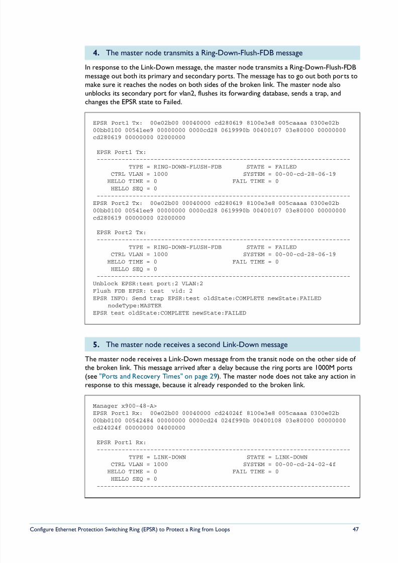
8/6/2019 Config Epsr Sd A
http://slidepdf.com/reader/full/config-epsr-sd-a 47/54
Configure Ethernet Protection Switching Ring (EPSR) to Protect a Ring from Loops 47
In response to the Link-Down message, the master node transmits a Ring-Down-Flush-FDBmessage out both its primary and secondary ports. The message has to go out both ports tomake sure it reaches the nodes on both sides of the broken link. The master node alsounblocks its secondary port for vlan2, flushes its forwarding database, sends a trap, andchanges the EPSR state to Failed.
The master node receives a Link-Down message from the transit node on the other side of the broken link. This message arrived after a delay because the ring ports are 1000M ports(see "Ports and Recovery Times" on page 29). The master node does not take any action inresponse to this message, because it already responded to the broken link.
4. The master node transmits a Ring-Down-Flush-FDB message
EPSR Port1 Tx: 00e02b00 00040000 cd280619 8100e3e8 005caaaa 0300e02b00bb0100 00541ee9 00000000 0000cd28 0619990b 00400107 03e80000 00000000cd280619 00000000 02000000
EPSR Port1 Tx:-----------------------------------------------------------------------
TYPE = RING-DOWN-FLUSH-FDB STATE = FAILEDCTRL VLAN = 1000 SYSTEM = 00-00-cd-28-06-19
HELLO TIME = 0 FAIL TIME = 0HELLO SEQ = 0
-----------------------------------------------------------------------EPSR Port2 Tx: 00e02b00 00040000 cd280619 8100e3e8 005caaaa 0300e02b00bb0100 00541ee9 00000000 0000cd28 0619990b 00400107 03e80000 00000000cd280619 00000000 02000000
EPSR Port2 Tx:-----------------------------------------------------------------------
TYPE = RING-DOWN-FLUSH-FDB STATE = FAILEDCTRL VLAN = 1000 SYSTEM = 00-00-cd-28-06-19
HELLO TIME = 0 FAIL TIME = 0HELLO SEQ = 0
-----------------------------------------------------------------------Unblock EPSR:test port:2 VLAN:2Flush FDB EPSR: test vid: 2
EPSR INFO: Send trap EPSR:test oldState:COMPLETE newState:FAILEDnodeType:MASTER
EPSR test oldState:COMPLETE newState:FAILED
5. The master node receives a second Link-Down message
Manager x900-48-A>EPSR Port1 Rx: 00e02b00 00040000 cd24024f 8100e3e8 005caaaa 0300e02b00bb0100 00542484 00000000 0000cd24 024f990b 00400108 03e80000 00000000cd24024f 00000000 04000000
EPSR Port1 Rx:-----------------------------------------------------------------------
TYPE = LINK-DOWN STATE = LINK-DOWNCTRL VLAN = 1000 SYSTEM = 00-00-cd-24-02-4f
HELLO TIME = 0 FAIL TIME = 0HELLO SEQ = 0
-----------------------------------------------------------------------
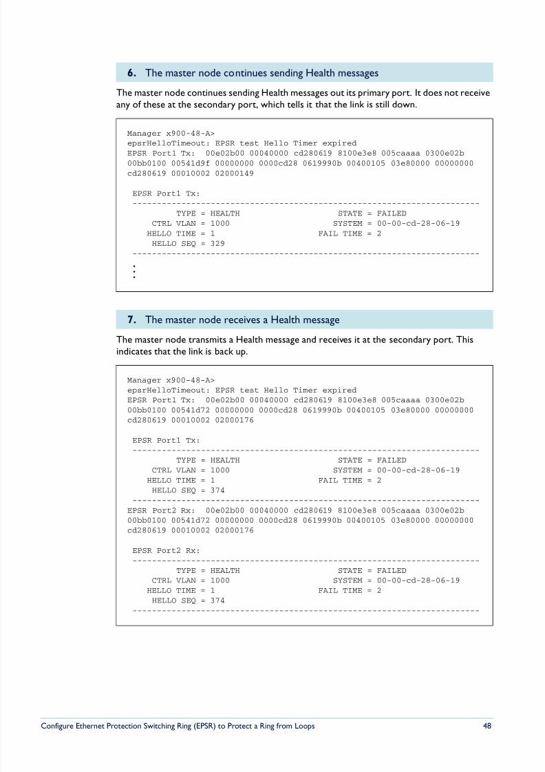
8/6/2019 Config Epsr Sd A
http://slidepdf.com/reader/full/config-epsr-sd-a 48/54
Configure Ethernet Protection Switching Ring (EPSR) to Protect a Ring from Loops 48
The master node continues sending Health messages out its primary port. It does not receiveany of these at the secondary port, which tells it that the link is still down.
The master node transmits a Health message and receives it at the secondary port. Thisindicates that the link is back up.
6. The master node continues sending Health messages
Manager x900-48-A>epsrHelloTimeout: EPSR test Hello Timer expiredEPSR Port1 Tx: 00e02b00 00040000 cd280619 8100e3e8 005caaaa 0300e02b00bb0100 00541d9f 00000000 0000cd28 0619990b 00400105 03e80000 00000000cd280619 00010002 02000149
EPSR Port1 Tx:-----------------------------------------------------------------------
TYPE = HEALTH STATE = FAILEDCTRL VLAN = 1000 SYSTEM = 00-00-cd-28-06-19
HELLO TIME = 1 FAIL TIME = 2HELLO SEQ = 329
-----------------------------------------------------------------------
.
..
7. The master node receives a Health message
Manager x900-48-A>epsrHelloTimeout: EPSR test Hello Timer expiredEPSR Port1 Tx: 00e02b00 00040000 cd280619 8100e3e8 005caaaa 0300e02b00bb0100 00541d72 00000000 0000cd28 0619990b 00400105 03e80000 00000000cd280619 00010002 02000176
EPSR Port1 Tx:-----------------------------------------------------------------------
TYPE = HEALTH STATE = FAILEDCTRL VLAN = 1000 SYSTEM = 00-00-cd-28-06-19
HELLO TIME = 1 FAIL TIME = 2HELLO SEQ = 374
-----------------------------------------------------------------------EPSR Port2 Rx: 00e02b00 00040000 cd280619 8100e3e8 005caaaa 0300e02b00bb0100 00541d72 00000000 0000cd28 0619990b 00400105 03e80000 00000000cd280619 00010002 02000176
EPSR Port2 Rx:-----------------------------------------------------------------------
TYPE = HEALTH STATE = FAILEDCTRL VLAN = 1000 SYSTEM = 00-00-cd-28-06-19
HELLO TIME = 1 FAIL TIME = 2HELLO SEQ = 374
-----------------------------------------------------------------------
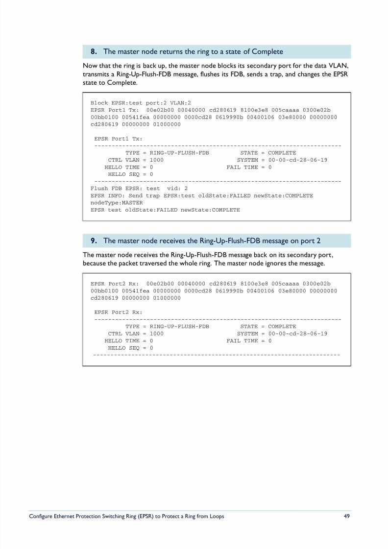
8/6/2019 Config Epsr Sd A
http://slidepdf.com/reader/full/config-epsr-sd-a 49/54
Configure Ethernet Protection Switching Ring (EPSR) to Protect a Ring from Loops 49
Now that the ring is back up, the master node blocks its secondary port for the data VLAN,transmits a Ring-Up-Flush-FDB message, flushes its FDB, sends a trap, and changes the EPSRstate to Complete.
The master node receives the Ring-Up-Flush-FDB message back on its secondary port,because the packet traversed the whole ring. The master node ignores the message.
8. The master node returns the ring to a state of Complete
Block EPSR:test port:2 VLAN:2EPSR Port1 Tx: 00e02b00 00040000 cd280619 8100e3e8 005caaaa 0300e02b00bb0100 00541fea 00000000 0000cd28 0619990b 00400106 03e80000 00000000cd280619 00000000 01000000
EPSR Port1 Tx:-----------------------------------------------------------------------
TYPE = RING-UP-FLUSH-FDB STATE = COMPLETECTRL VLAN = 1000 SYSTEM = 00-00-cd-28-06-19
HELLO TIME = 0 FAIL TIME = 0HELLO SEQ = 0
-----------------------------------------------------------------------Flush FDB EPSR: test vid: 2EPSR INFO: Send trap EPSR:test oldState:FAILED newState:COMPLETEnodeType:MASTEREPSR test oldState:FAILED newState:COMPLETE
9. The master node receives the Ring-Up-Flush-FDB message on port 2
EPSR Port2 Rx: 00e02b00 00040000 cd280619 8100e3e8 005caaaa 0300e02b
00bb0100 00541fea 00000000 0000cd28 0619990b 00400106 03e80000 00000000cd280619 00000000 01000000
EPSR Port2 Rx:-----------------------------------------------------------------------
TYPE = RING-UP-FLUSH-FDB STATE = COMPLETECTRL VLAN = 1000 SYSTEM = 00-00-cd-28-06-19
HELLO TIME = 0 FAIL TIME = 0HELLO SEQ = 0
-----------------------------------------------------------------------
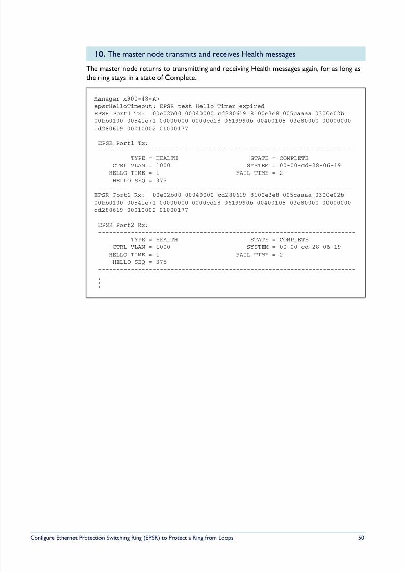
8/6/2019 Config Epsr Sd A
http://slidepdf.com/reader/full/config-epsr-sd-a 50/54
Configure Ethernet Protection Switching Ring (EPSR) to Protect a Ring from Loops 50
The master node returns to transmitting and receiving Health messages again, for as long asthe ring stays in a state of Complete.
10. The master node transmits and receives Health messages
Manager x900-48-A>epsrHelloTimeout: EPSR test Hello Timer expiredEPSR Port1 Tx: 00e02b00 00040000 cd280619 8100e3e8 005caaaa 0300e02b00bb0100 00541e71 00000000 0000cd28 0619990b 00400105 03e80000 00000000cd280619 00010002 01000177
EPSR Port1 Tx:-----------------------------------------------------------------------
TYPE = HEALTH STATE = COMPLETECTRL VLAN = 1000 SYSTEM = 00-00-cd-28-06-19
HELLO TIME = 1 FAIL TIME = 2HELLO SEQ = 375
-----------------------------------------------------------------------EPSR Port2 Rx: 00e02b00 00040000 cd280619 8100e3e8 005caaaa 0300e02b
00bb0100 00541e71 00000000 0000cd28 0619990b 00400105 03e80000 00000000cd280619 00010002 01000177
EPSR Port2 Rx:-----------------------------------------------------------------------
TYPE = HEALTH STATE = COMPLETECTRL VLAN = 1000 SYSTEM = 00-00-cd-28-06-19
HELLO TIME = 1 FAIL TIME = 2HELLO SEQ = 375
-----------------------------------------------------------------------
.
.
.
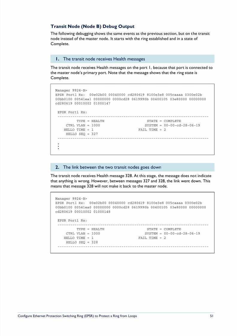
8/6/2019 Config Epsr Sd A
http://slidepdf.com/reader/full/config-epsr-sd-a 51/54
Configure Ethernet Protection Switching Ring (EPSR) to Protect a Ring from Loops 51
Transit Node (Node B) Debug Output
The following debugging shows the same events as the previous section, but on the transitnode instead of the master node. It starts with the ring established and in a state of Complete.
The transit node receives Health messages on the port 1, because that port is connected tothe master node’s primary port. Note that the message shows that the ring state isComplete.
The transit node receives Health message 328. At this stage, the message does not indicatethat anything is wrong. However, between messages 327 and 328, the link went down. Thismeans that message 328 will not make it back to the master node.
1. The transit node receives Health messages
Manager 9924-B>EPSR Port1 Rx: 00e02b00 00040000 cd280619 8100e3e8 005caaaa 0300e02b00bb0100 00541ea1 00000000 0000cd28 0619990b 00400105 03e80000 00000000cd280619 00010002 01000147
EPSR Port1 Rx:
-----------------------------------------------------------------------TYPE = HEALTH STATE = COMPLETECTRL VLAN = 1000 SYSTEM = 00-00-cd-28-06-19
HELLO TIME = 1 FAIL TIME = 2HELLO SEQ = 327
-----------------------------------------------------------------------
.
.
.
2. The link between the two transit nodes goes down
Manager 9924-B>EPSR Port1 Rx: 00e02b00 00040000 cd280619 8100e3e8 005caaaa 0300e02b00bb0100 00541ea0 00000000 0000cd28 0619990b 00400105 03e80000 00000000cd280619 00010002 01000148
EPSR Port1 Rx:-----------------------------------------------------------------------
TYPE = HEALTH STATE = COMPLETECTRL VLAN = 1000 SYSTEM = 00-00-cd-28-06-19
HELLO TIME = 1 FAIL TIME = 2HELLO SEQ = 328
-----------------------------------------------------------------------
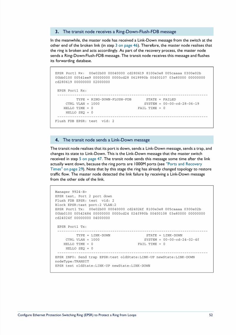
8/6/2019 Config Epsr Sd A
http://slidepdf.com/reader/full/config-epsr-sd-a 52/54
Configure Ethernet Protection Switching Ring (EPSR) to Protect a Ring from Loops 52
In the meanwhile, the master node has received a Link-Down message from the switch at theother end of the broken link (in step 3 on page 46). Therefore, the master node realises thatthe ring is broken and acts accordingly. As part of the recovery process, the master nodesends a Ring-Down-Flush-FDB message. The transit node receives this message and flushesits forwarding database.
The transit node realises that its port is down, sends a Link-Down message, sends a trap, andchanges its state to Link-Down. This is the Link-Down message that the master switchreceived in step 5 on page 47. The transit node sends this message some time after the link actually went down, because the ring ports are 1000M ports (see "Ports and RecoveryTimes" on page 29). Note that by this stage the ring has already changed topology to restore
traffic flow. The master node detected the link failure by receiving a Link-Down messagefrom the other side of the link.
3. The transit node receives a Ring-Down-Flush-FDB message
EPSR Port1 Rx: 00e02b00 00040000 cd280619 8100e3e8 005caaaa 0300e02b00bb0100 00541ee9 00000000 0000cd28 0619990b 00400107 03e80000 00000000cd280619 00000000 02000000
EPSR Port1 Rx:-----------------------------------------------------------------------
TYPE = RING-DOWN-FLUSH-FDB STATE = FAILEDCTRL VLAN = 1000 SYSTEM = 00-00-cd-28-06-19
HELLO TIME = 0 FAIL TIME = 0HELLO SEQ = 0
-----------------------------------------------------------------------Flush FDB EPSR: test vid: 2
4. The transit node sends a Link-Down message
Manager 9924-B>EPSR test, Port 2 port downFlush FDB EPSR: test vid: 2Block EPSR:test port:2 VLAN:2EPSR Port1 Tx: 00e02b00 00040000 cd24024f 8100e3e8 005caaaa 0300e02b00bb0100 00542484 00000000 0000cd24 024f990b 00400108 03e80000 00000000cd24024f 00000000 04000000
EPSR Port1 Tx:-----------------------------------------------------------------------
TYPE = LINK-DOWN STATE = LINK-DOWNCTRL VLAN = 1000 SYSTEM = 00-00-cd-24-02-4f
HELLO TIME = 0 FAIL TIME = 0HELLO SEQ = 0
-----------------------------------------------------------------------EPSR INFO: Send trap EPSR:test oldState:LINK-UP newState:LINK-DOWNnodeType:TRANSITEPSR test oldState:LINK-UP newState:LINK-DOWN
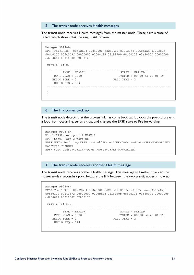
8/6/2019 Config Epsr Sd A
http://slidepdf.com/reader/full/config-epsr-sd-a 53/54
Configure Ethernet Protection Switching Ring (EPSR) to Protect a Ring from Loops 53
The transit node receives Health messages from the master node. These have a state of Failed, which shows that the ring is still broken.
The transit node detects that the broken link has come back up. It blocks the port to preventa loop from occurring, sends a trap, and changes the EPSR state to Pre-forwarding.
The transit node receives another Health message. This message will make it back to themaster node’s secondary port, because the link between the two transit nodes is now up.
5. The transit node receives Health messages
Manager 9924-B>EPSR Port1 Rx: 00e02b00 00040000 cd280619 8100e3e8 005caaaa 0300e02b00bb0100 00541d9f 00000000 0000cd28 0619990b 00400105 03e80000 00000000cd280619 00010002 02000149
EPSR Port1 Rx:-----------------------------------------------------------------------
TYPE = HEALTH STATE = FAILEDCTRL VLAN = 1000 SYSTEM = 00-00-cd-28-06-19
HELLO TIME = 1 FAIL TIME = 2HELLO SEQ = 329
-----------------------------------------------------------------------
.
.
.
6. The link comes back up
Manager 9924-B>Block EPSR:test port:2 VLAN:2EPSR test, Port 2 port upEPSR INFO: Send trap EPSR:test oldState:LINK-DOWN newState:PRE-FORWARDINGnodeType:TRANSITEPSR test oldState:LINK-DOWN newState:PRE-FORWARDING
7. The transit node receives another Health message
Manager 9924-B>EPSR Port1 Rx: 00e02b00 00040000 cd280619 8100e3e8 005caaaa 0300e02b
00bb0100 00541d72 00000000 0000cd28 0619990b 00400105 03e80000 00000000cd280619 00010002 02000176
EPSR Port1 Rx:-----------------------------------------------------------------------
TYPE = HEALTH STATE = FAILEDCTRL VLAN = 1000 SYSTEM = 00-00-cd-28-06-19
HELLO TIME = 1 FAIL TIME = 2HELLO SEQ = 374
-----------------------------------------------------------------------
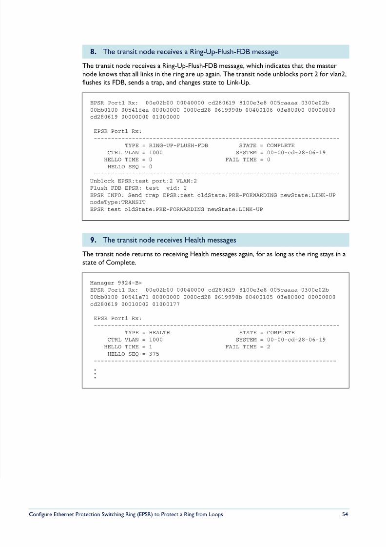
8/6/2019 Config Epsr Sd A
http://slidepdf.com/reader/full/config-epsr-sd-a 54/54
The transit node receives a Ring-Up-Flush-FDB message, which indicates that the masternode knows that all links in the ring are up again. The transit node unblocks port 2 for vlan2,flushes its FDB, sends a trap, and changes state to Link-Up.
The transit node returns to receiving Health messages again, for as long as the ring stays in astate of Complete.
8. The transit node receives a Ring-Up-Flush-FDB message
EPSR Port1 Rx: 00e02b00 00040000 cd280619 8100e3e8 005caaaa 0300e02b00bb0100 00541fea 00000000 0000cd28 0619990b 00400106 03e80000 00000000cd280619 00000000 01000000
EPSR Port1 Rx:-----------------------------------------------------------------------
TYPE = RING-UP-FLUSH-FDB STATE = COMPLETECTRL VLAN = 1000 SYSTEM = 00-00-cd-28-06-19
HELLO TIME = 0 FAIL TIME = 0HELLO SEQ = 0
-----------------------------------------------------------------------Unblock EPSR:test port:2 VLAN:2Flush FDB EPSR: test vid: 2EPSR INFO: Send trap EPSR:test oldState:PRE-FORWARDING newState:LINK-UPnodeType:TRANSITEPSR test oldState:PRE-FORWARDING newState:LINK-UP
9. The transit node receives Health messages
Manager 9924-B>
EPSR Port1 Rx: 00e02b00 00040000 cd280619 8100e3e8 005caaaa 0300e02b00bb0100 00541e71 00000000 0000cd28 0619990b 00400105 03e80000 00000000cd280619 00010002 01000177
EPSR Port1 Rx:-----------------------------------------------------------------------
TYPE = HEALTH STATE = COMPLETECTRL VLAN = 1000 SYSTEM = 00-00-cd-28-06-19
HELLO TIME = 1 FAIL TIME = 2HELLO SEQ = 375
----------------------------------------------------------------------
.
.
.
Related Documents