W.H. Mason 2/12/06 4-1 4. Aircraft Configuration Design Options 4.1 Overview As hard as it might be for the aerodynamicist to imagine, aircraft designs are the result of the integration of several technologies, of which aerodynamics, although a key, is only one. Thus the aerodynamicis t is responsible as a team member for the overall concept . Traditionally, the other technologies are propulsion, structures and flight control. For many military aircraft stealth has become a critical technology impacting the configuration shape. Some notes describing stealth issues for aerodynamic design are given in Appendix B. To achieve a successful design the aerodynamicist must be a strong advocate for effective aerodynamic design. If this isn’t done, the team will likely not produce a winning design. Recent examples where the aerodynamics group’s failure to persuade the company of aerodynamics’ importance include reducing manufacturing costs by eliminating wing camber and twist, and allowing the stealth group to dominate the design at the expense of aerodynamic maneuvering performance. In one case enormous development costs were incurred, while still resulting in a reduced performance aircraft. In the other case the proposed design lost to the competition. To be an effective advocate, the aerodynamicist must have an understanding of the configuration options available and the aerodynamic implications. So where do we start when considering the aerodynamic layout of an airplane? In general, form follows function. We decide on candidate configurations based on what the airplane is supposed to do. Generally, this starts with a decision on the type of payload and the “mission” the airplane is supposed to carry out with this payload. This is expressed generally in terms of • What does it carry? • How far does it go? • How fast is it supposed to fly? • What are the field requirements? (how short is the runway?) • Are there any maneuvering and/or acceleration requirements? Another consideration is the specific safety-related requirements that must be satisfied. For commercial aircraft this means satisfying the Federal Air Regulations (FARs) and JARs for Europe. Satisfying these requirements defines the takeoff and landing distances, engine-out performance requirements, noise limits, icing performance, and emergency evacuation among many others. Military aircraft also have numerous requirements. In both situations the emphasis is on safety, including the handling qualities. Appendix C provides a few details of these requirements.

Welcome message from author
This document is posted to help you gain knowledge. Please leave a comment to let me know what you think about it! Share it to your friends and learn new things together.
Transcript
8/8/2019 Config a Erode Sign Opt
http://slidepdf.com/reader/full/config-a-erode-sign-opt 1/23
W.H. Mason
2/12/06 4-1
4. Aircraft Configuration Design Options4.1 Overview
As hard as it might be for the aerodynamicist to imagine, aircraft designs are the result of the
integration of several technologies, of which aerodynamics, although a key, is only one. Thus the
aerodynamicist is responsible as a team member for the overall concept . Traditionally, the other
technologies are propulsion, structures and flight control. For many military aircraft stealth has
become a critical technology impacting the configuration shape. Some notes describing stealth
issues for aerodynamic design are given in Appendix B.
To achieve a successful design the aerodynamicist must be a strong advocate for effective
aerodynamic design. If this isn’t done, the team will likely not produce a winning design. Recentexamples where the aerodynamics group’s failure to persuade the company of aerodynamics’
importance include reducing manufacturing costs by eliminating wing camber and twist, and
allowing the stealth group to dominate the design at the expense of aerodynamic maneuvering
performance. In one case enormous development costs were incurred, while still resulting in a
reduced performance aircraft. In the other case the proposed design lost to the competition. To be
an effective advocate, the aerodynamicist must have an understanding of the configuration
options available and the aerodynamic implications.
So where do we start when considering the aerodynamic layout of an airplane? In general,
form follows function. We decide on candidate configurations based on what the airplane is
supposed to do. Generally, this starts with a decision on the type of payload and the “mission”
the airplane is supposed to carry out with this payload. This is expressed generally in terms of
• What does it carry?• How far does it go?• How fast is it supposed to fly?• What are the field requirements? (how short is the runway?)• Are there any maneuvering and/or acceleration requirements?
Another consideration is the specific safety-related requirements that must be satisfied. For
commercial aircraft this means satisfying the Federal Air Regulations (FARs) and JARs for
Europe. Satisfying these requirements defines the takeoff and landing distances, engine-out
performance requirements, noise limits, icing performance, and emergency evacuation among
many others. Military aircraft also have numerous requirements. In both situations the emphasis
is on safety, including the handling qualities. Appendix C provides a few details of these
requirements.
8/8/2019 Config a Erode Sign Opt
http://slidepdf.com/reader/full/config-a-erode-sign-opt 2/23
4-2 Configuration Aerodynamics
2/12/06
With this start, the aerodynamicist, reluctantly allowing other members of the design team
and management to participate, develops a concept architecture and shape that responds to the
mission . At the outset, the following list describes the considerations associated with defining a
configuration concept. At this stage we begin to see that configuration design resembles putting a
puzzle together. These components all have to be completely integrated.Configuration Concept:
• Lifting surface arrangement• Control surface(s) location• Propulsion system selection• Payload• Landing Gear
The components listed above must be coordinated in such a fashion that the airplane satisfies
the requirements given in the following list. The configuration designer works to satisfy these
requirements with input from the various team members. This is where the team member thatdominates can distort the design in a way that keeps it from being the right response to the design
requirements. To be successful the following criteria must be met.
Good Aircraft
• Aerodynamically efficient, including propulsion integration (streamlining!)• Must balance near stability level for minimum drag• Landing gear must be located relative to cg to allow rotation at takeoff • Adequate control authority must be available throughout the flight envelope• Design to build easily (cheaply) and have low maintenance costs• Today, commercial airplanes must be quiet and nonpolluting
Two books do an especially good job of covering the aerodynamic layout issues. The first is by
Ray Whitford 1, and the second by Abzug and Larrabee 2. In both cases the titles are slightly
misleading. Design books that discuss configuration options are by Raymer 3 and Roskam 4
We can translate these desirable properties into specific aerodynamic characteristics.
Essentially, they can be given as:
Design for Performance
• Reduce minimum drag:- Minimize the wetted area to reduce skin friction- Streamline to reduce flow separation (pressure drag)- Distribute area smoothly, especially for supersonic a/c (area ruling)- Consider laminar flow- Emphasize clean design/manufacture with few protuberances, steps or gaps
• Reduce drag due to lift:- Maximize span (must be traded against wing weight)- Tailor spanload to get a good span e, (twist)- Distribute lifting load longitudinally to reduce wave drag due to lift
(a supersonic requirement, note R.T. Jones’ oblique wing idea)- Camber as well as twist to integrate airfoil, maintain good 2D characteristics
8/8/2019 Config a Erode Sign Opt
http://slidepdf.com/reader/full/config-a-erode-sign-opt 3/23
W.H. Mason Aerodynamic Configuration Design Options 4-3
2/12/06
• Key constraints:- At cruise: buffet and overspeed constraints on the wing- Adequate high lift for field performance (simpler is cheaper)- Alpha tailscrape, ( C Lα goes down with sweep, AR)
Design for Handling Qualities
• Adequate control power is essential- Nose up pitching moment for stable vehicles- Nose down pitching moment for unstable vehicles- Yawing moment, especially for flying wings and fighters at Hi- α
- Consider the full range of cg’s.• Implies: must balance the configuration around the cg properly
FAA and Military Requirements
• Safety: for the aerodynamic configuration this means safe flying qualities- FAR Part 25 and some of Part 121 for commercial transports- MIL STD 1797 for military airplanes
• Ability to use the airplane as a stable weapons platform• Noise: community noise, FAR Part 36, no sonic booms over land(High L/D in the takeoff configuration reduces thrust requirements,makes the plane quieter)
To start considering the various configuration concepts, we use the successful transonic
commercial transport as a starting point. This configuration is mature. New commercial
transports have almost uniformly adopted this configuration and variations are minor. An
interesting comparison of two different transport configuration development philosophies is
available in the papers describing the development of the original Douglas DC-9 5 and Boeing
737 6 designs. Advances in performance and reduction in cost are currently obtained by
improvements in the contributing technologies.
After we establish the baseline, we will examine other configuration component concepts
that are often considered. We give a summary of the major options. Many, many other
innovations have been tried, and we make no attempt to be comprehensive.
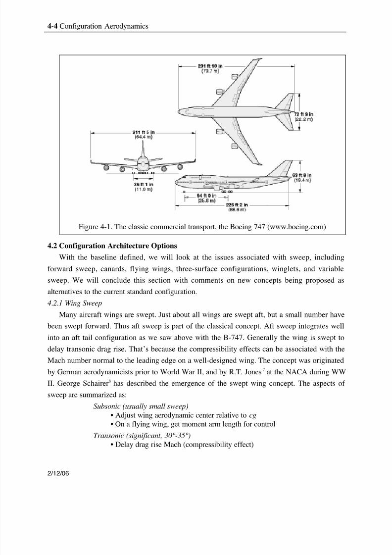
The Boeing 747 layout is shown in Figure 4-1. It meets the criteria cited above. The payload
is distributed around the cg. Longitudinal stability and control power comes from the horizontal
tail and elevator, which has a very useful moment arm. The vertical tail provides directional
stability, using the rudder for directional control. The wing/fuselage/landing gear setup allows
the wing to provide its lift near the center of gravity and positions the landing gear so that theairplane can rotate at takeoff speed and also provides for adequate rotation without scraping the
tail. This arrangement also results in low trimmed drag. The engines are located on pylons below
the wing. This arrangement allows the engine weight to counteract the wing lift, reducing the
wing root bending moment, resulting in a lighter wing. This engine location can also be designed
so that there is essentially no adverse aerodynamic interference.
8/8/2019 Config a Erode Sign Opt
http://slidepdf.com/reader/full/config-a-erode-sign-opt 4/23
4-4 Configuration Aerodynamics
2/12/06
4.2 Configuration Architecture Options
With the baseline defined, we will look at the issues associated with sweep, including
forward sweep, canards, flying wings, three-surface configurations, winglets, and variable
sweep. We will conclude this section with comments on new concepts being proposed as
alternatives to the current standard configuration.4.2.1 Wing Sweep
Many aircraft wings are swept. Just about all wings are swept aft, but a small number have
been swept forward. Thus aft sweep is part of the classical concept. Aft sweep integrates well
into an aft tail configuration as we saw above with the B-747. Generally the wing is swept to
delay transonic drag rise. That’s because the compressibility effects can be associated with the
Mach number normal to the leading edge on a well-designed wing. The concept was originated
by German aerodynamicists prior to World War II, and by R.T. Jones 7 at the NACA during WW
II. George Schairer 8 has described the emergence of the swept wing concept. The aspects of
sweep are summarized as:
Subsonic (usually small sweep)• Adjust wing aerodynamic center relative to cg• On a flying wing, get moment arm length for control
Transonic (significant, 30°-35°)• Delay drag rise Mach (compressibility effect)
Figure 4-1. The classic commercial transport, the Boeing 747 (www.boeing.com)
8/8/2019 Config a Erode Sign Opt
http://slidepdf.com/reader/full/config-a-erode-sign-opt 5/23
W.H. Mason Aerodynamic Configuration Design Options 4-5
2/12/06
Supersonic (large, 45°-70°)• Wing concept changes to slender wing theory, vortex flow wing
- Must distribute load longitudinally as well as laterally• Reduce max cross-sectional area and area variation occurs more slowly
Sweeping the wing is not without drawbacks. Wing sweep increases the wing weight for
fixed span since the length of the wing increases with sweep to get reach same wingspan. Inaddition, high-lift devices aren’t as effective when the trailing edge is swept. Also, the wing
tends to stall outboard first, leading to pitchup , a situation where the wing stops lifting well aft of
the center of gravity, while continuing to lift ahead of the center of gravity. This results in a
sudden nose up pitching moment, and an unstable slope. Pitchup is discussed in detail in the
paper by Shevell and Schaufele. 5 Finally, for aft sweep the wing tends to be flutter critical.
4.2.2 Why sweep the wing forward?
Several designs have adopted a forward swept wing. It was known for some time that a forward
swept wing has the same drag rise delay benefit as an aft swept wing. However, forward sweptwings tend to suffer from aeroelastic divergence. This prevented them from being considered for
most design concepts. One notable exception was a German bomber used in WW II (the Junkers
JU-287). The wing was swept forward so that the wing carry-through structure would be aft of
the bomb that was carried on the cg . After the war, this design team produced a transonic
business jet (the HFB-320 Hansajet), using the same logic to provide room for passengers,
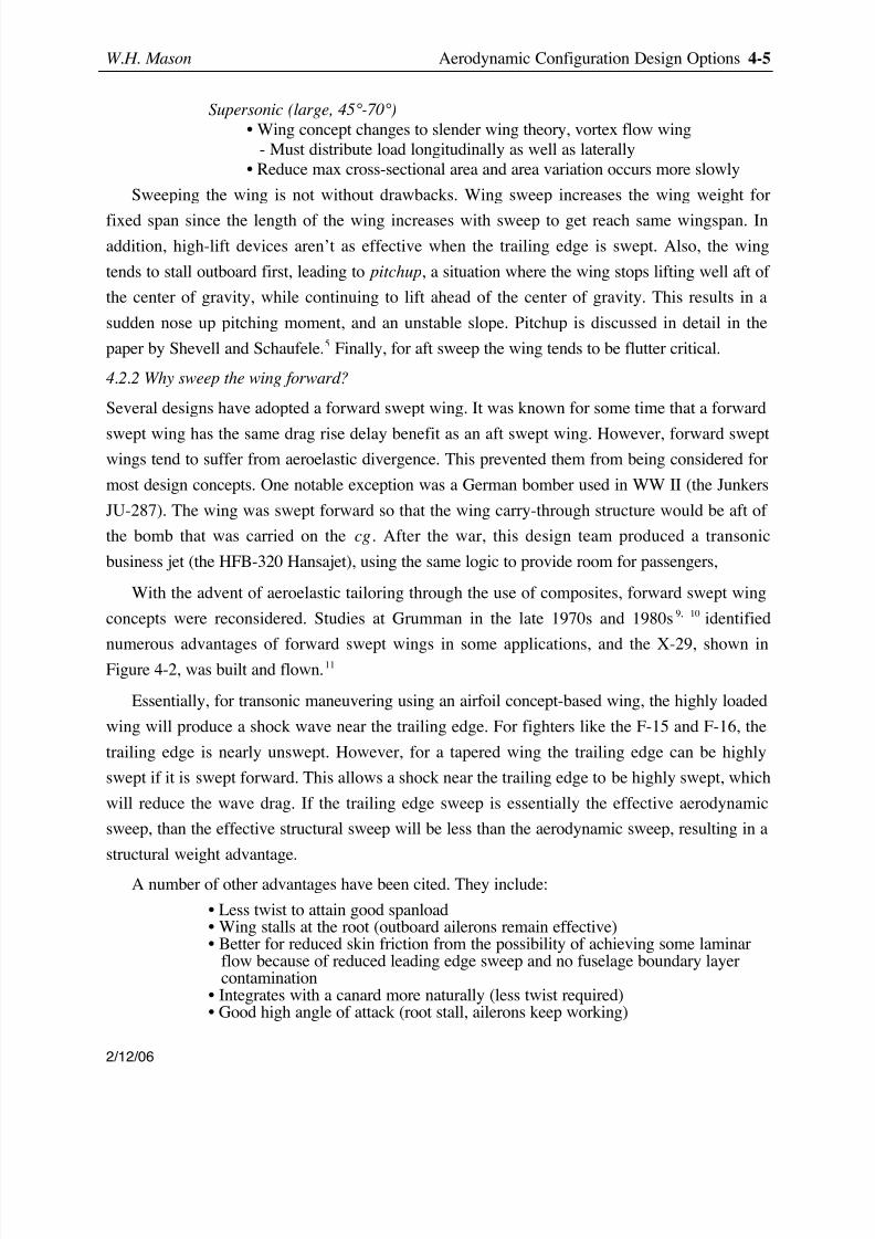
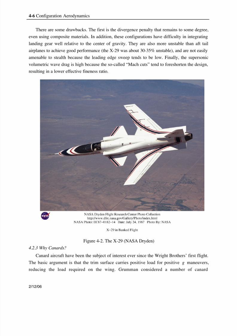
With the advent of aeroelastic tailoring through the use of composites, forward swept wing
concepts were reconsidered. Studies at Grumman in the late 1970s and 1980s 9, 10 identified
numerous advantages of forward swept wings in some applications, and the X-29, shown inFigure 4-2, was built and flown. 11
Essentially, for transonic maneuvering using an airfoil concept-based wing, the highly loaded
wing will produce a shock wave near the trailing edge. For fighters like the F-15 and F-16, the
trailing edge is nearly unswept. However, for a tapered wing the trailing edge can be highly
swept if it is swept forward. This allows a shock near the trailing edge to be highly swept, which
will reduce the wave drag. If the trailing edge sweep is essentially the effective aerodynamic
sweep, than the effective structural sweep will be less than the aerodynamic sweep, resulting in a
structural weight advantage.
A number of other advantages have been cited. They include:
• Less twist to attain good spanload• Wing stalls at the root (outboard ailerons remain effective)• Better for reduced skin friction from the possibility of achieving some laminar
flow because of reduced leading edge sweep and no fuselage boundary layercontamination
• Integrates with a canard more naturally (less twist required)• Good high angle of attack (root stall, ailerons keep working)
8/8/2019 Config a Erode Sign Opt
http://slidepdf.com/reader/full/config-a-erode-sign-opt 6/23
4-6 Configuration Aerodynamics
2/12/06
There are some drawbacks. The first is the divergence penalty that remains to some degree,
even using composite materials. In addition, these configurations have difficulty in integrating
landing gear well relative to the center of gravity. They are also more unstable than aft tail
airplanes to achieve good performance (the X-29 was about 30-35% unstable), and are not easily
amenable to stealth because the leading edge sweep tends to be low. Finally, the supersonicvolumetric wave drag is high because the so-called “Mach cuts” tend to foreshorten the design,
resulting in a lower effective fineness ratio.
Figure 4-2. The X-29 (NASA Dryden)
4.2.3 Why Canards?
Canard aircraft have been the subject of interest ever since the Wright Brothers’ first flight.
The basic argument is that the trim surface carries positive load for positive g maneuvers,
reducing the load required on the wing. Grumman considered a number of canard
8/8/2019 Config a Erode Sign Opt
http://slidepdf.com/reader/full/config-a-erode-sign-opt 7/23
W.H. Mason Aerodynamic Configuration Design Options 4-7
2/12/06
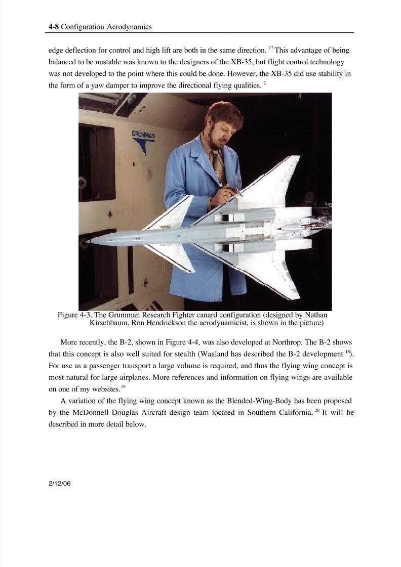
configurations, 12,13 including the Research Fighter Configuration (RFC) shown in Figure. 4-3. In
general I think canard configurations should only be considered for designs with stringent
requirements for both supersonic cruise and transonic maneuver. The recent generation of
European fighters has adopted canard configurations. The SAAB JAS 39 Grippen is a good
example.14
Issues related to the use of canards include:
• Reduces subsonic-supersonic aerodynamic center shift.• Needs to be balanced unstable to take full advantage of performance.• Drawback: the downwash from the canard unloads wing
(for forward swept wing concepts this is good).• If balanced stable, C L on the canard is much higher than the wing.• If balanced unstable, the control system design is expensive.• Acceptable high angle of attack lateral/directional characteristics are very hard
to obtain.
Canard configurations are more difficult to develop than traditional aft-swept wingconfigurations. Note in Figure 4-3 that the inlets are behind the canards, so that it was possible
that under some circumstances the wake from the canard could enter the inlets. When balanced
stable, the demands on the canard airfoil are quite high. It appears that when the airfoils used on
the canards of early Rutan designs encountered rain, the boundary layer transitioned early and as
a result didn’t produce the required lift to allow level flight. These airplanes had to get out of the
rain before they encountered the ground! Garrison has given a particularly cogent discussion of
canard configurations, primarily for general aviation designs. 15
4.2.4 Why a flying wing?
Another concept popular with aerodynamicists is the flying wing. The advantage is that
eliminating the surface area of the fuselage and control surfaces reduces the parasite drag,
improving the aerodynamic efficiency. You also eliminate the weight of the tail. This concept
can work well if extreme maneuverability is not needed. The volume distribution can be an issue.
John Northrop devoted much of his career to the development of flying wings, and the XB-35
and YB-49 bombers employed this concept. For a variety of reasons these designs weren’t
practical at the time. John Northrop’s excellent paper on flying wings is still worth reading. 16
One particularly important technology not available to John Northrop was the modern
digital flight control system. This concept makes extensive use of stability and control
augmentation systems. For a wing without a vertical tail and rudder, directional stability and
control requires special attention. The usual method of producing yawing moments is to use so-
called “drag rudders”, which consist of split flaps on the outboard portion of the wings. The
flying wing is also synergistic with relaxed static stability. This is because when the airplane is
unstable the trailing edge will be deflected down to bring the nose up. This means that trailing
8/8/2019 Config a Erode Sign Opt
http://slidepdf.com/reader/full/config-a-erode-sign-opt 8/23
4-8 Configuration Aerodynamics
2/12/06
edge deflection for control and high lift are both in the same direction. 17 This advantage of being
balanced to be unstable was known to the designers of the XB-35, but flight control technology
was not developed to the point where this could be done. However, the XB-35 did use stability in
the form of a yaw damper to improve the directional flying qualities. 2
Figure 4-3. The Grumman Research Fighter canard configuration (designed by NathanKirschbaum, Ron Hendrickson the aerodynamicist, is shown in the picture)
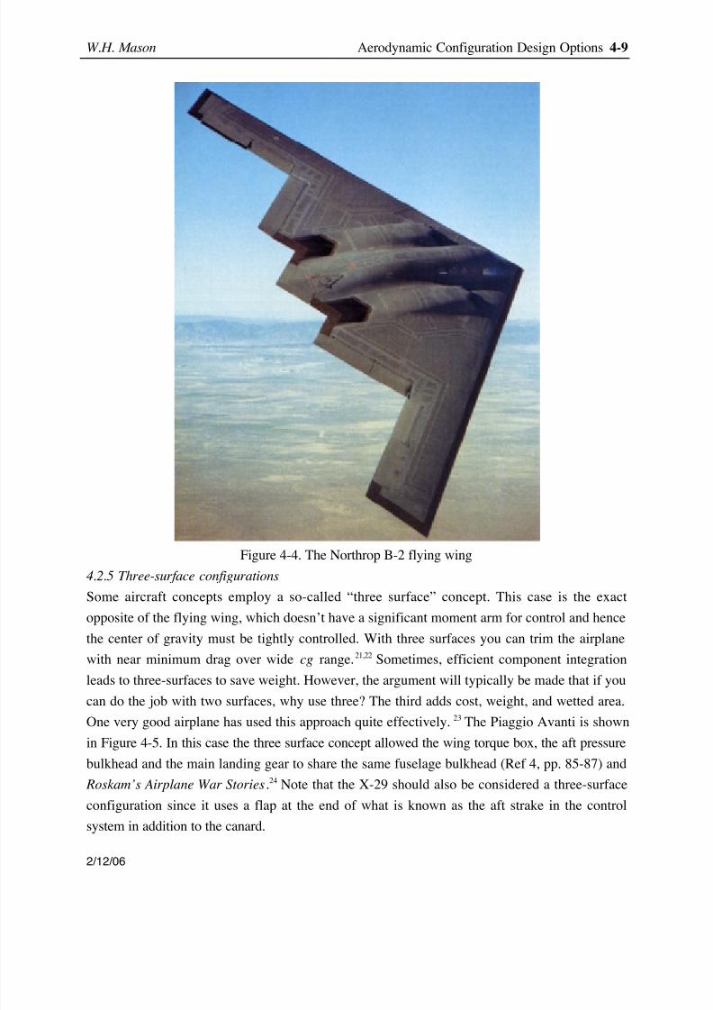
More recently, the B-2, shown in Figure 4-4, was also developed at Northrop. The B-2 shows
that this concept is also well suited for stealth (Waaland has described the B-2 development 18).
For use as a passenger transport a large volume is required, and thus the flying wing concept is
most natural for large airplanes. More references and information on flying wings are available
on one of my websites. 19
A variation of the flying wing concept known as the Blended-Wing-Body has been proposed
by the McDonnell Douglas Aircraft design team located in Southern California. 20 It will be
described in more detail below.
8/8/2019 Config a Erode Sign Opt
http://slidepdf.com/reader/full/config-a-erode-sign-opt 9/23
W.H. Mason Aerodynamic Configuration Design Options 4-9
2/12/06
Figure 4-4. The Northrop B-2 flying wing
4.2.5 Three-surface configurations
Some aircraft concepts employ a so-called “three surface” concept. This case is the exact
opposite of the flying wing, which doesn’t have a significant moment arm for control and hence
the center of gravity must be tightly controlled. With three surfaces you can trim the airplane
with near minimum drag over wide cg range. 21,22 Sometimes, efficient component integration
leads to three-surfaces to save weight. However, the argument will typically be made that if you
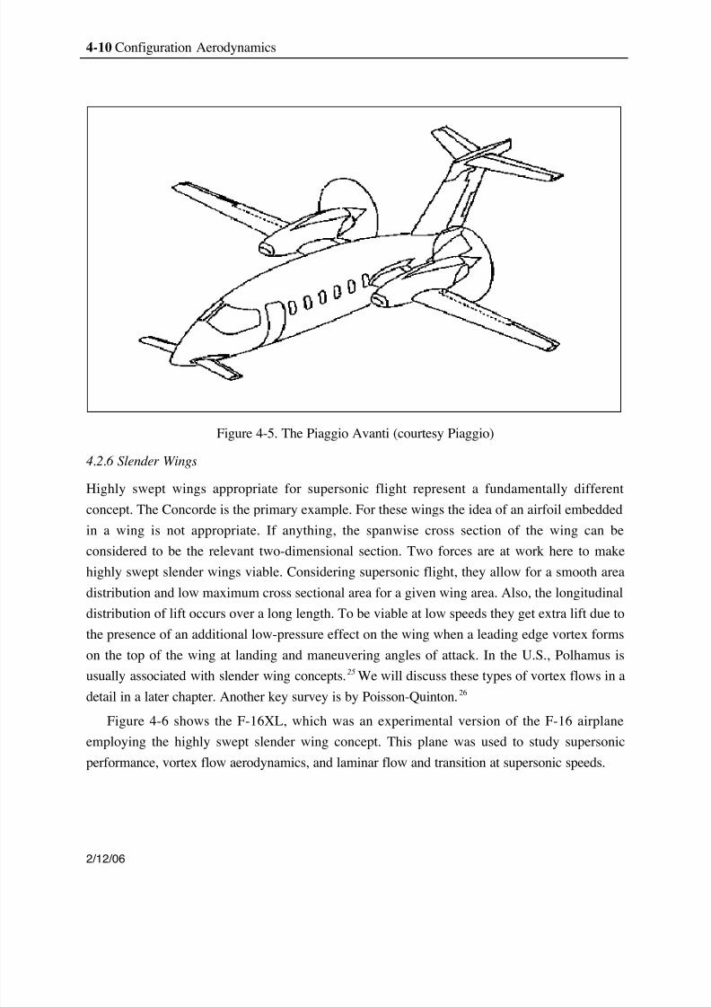
can do the job with two surfaces, why use three? The third adds cost, weight, and wetted area.One very good airplane has used this approach quite effectively. 23 The Piaggio Avanti is shown
in Figure 4-5. In this case the three surface concept allowed the wing torque box, the aft pressure
bulkhead and the main landing gear to share the same fuselage bulkhead (Ref 4, pp. 85-87) and
Roskam’s Airplane War Stories .24 Note that the X-29 should also be considered a three-surface
configuration since it uses a flap at the end of what is known as the aft strake in the control
system in addition to the canard.
8/8/2019 Config a Erode Sign Opt
http://slidepdf.com/reader/full/config-a-erode-sign-opt 10/23
4-10 Configuration Aerodynamics
2/12/06
Figure 4-5. The Piaggio Avanti (courtesy Piaggio)
4.2.6 Slender Wings
Highly swept wings appropriate for supersonic flight represent a fundamentally different
concept. The Concorde is the primary example. For these wings the idea of an airfoil embedded
in a wing is not appropriate. If anything, the spanwise cross section of the wing can beconsidered to be the relevant two-dimensional section. Two forces are at work here to make
highly swept slender wings viable. Considering supersonic flight, they allow for a smooth area
distribution and low maximum cross sectional area for a given wing area. Also, the longitudinal
distribution of lift occurs over a long length. To be viable at low speeds they get extra lift due to
the presence of an additional low-pressure effect on the wing when a leading edge vortex forms
on the top of the wing at landing and maneuvering angles of attack. In the U.S., Polhamus is
usually associated with slender wing concepts. 25 We will discuss these types of vortex flows in a
detail in a later chapter. Another key survey is by Poisson-Quinton. 26
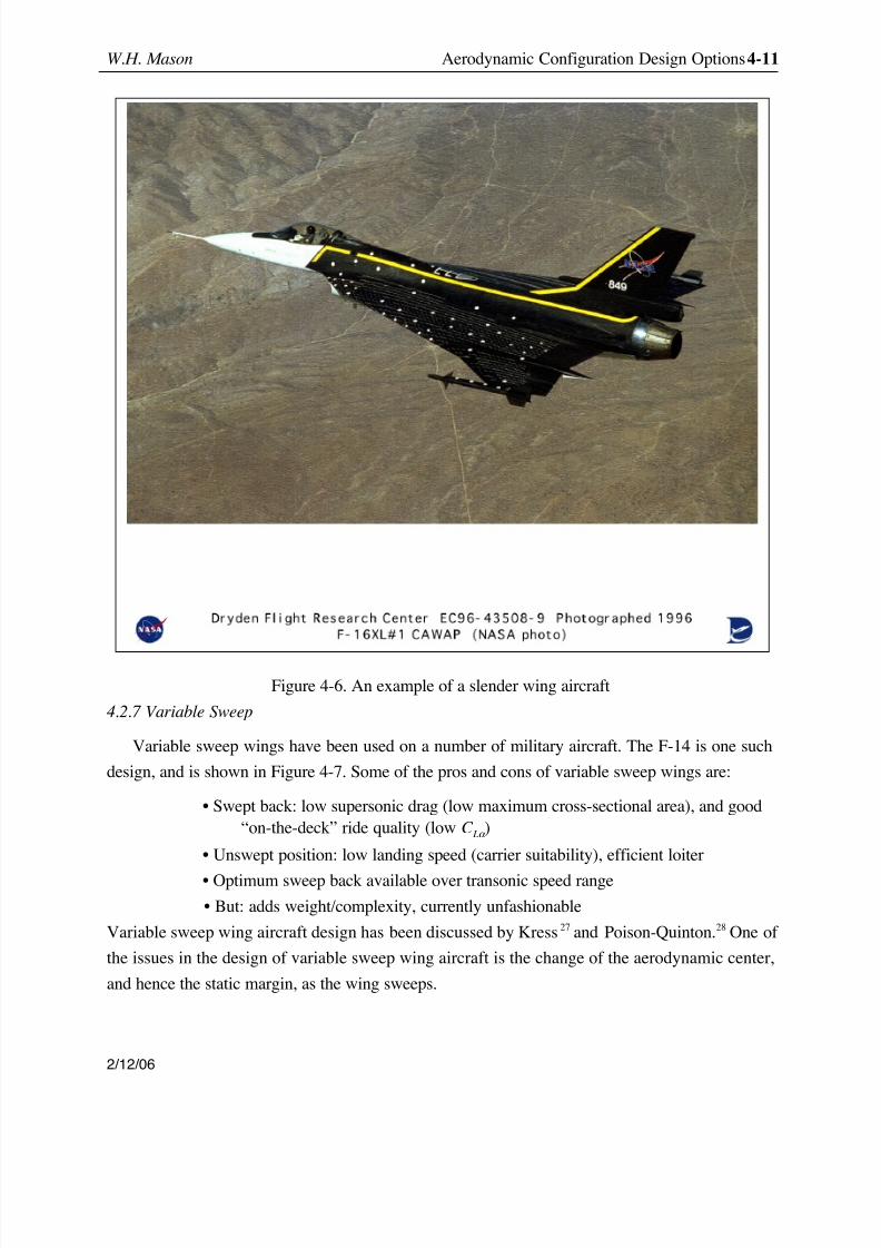
Figure 4-6 shows the F-16XL, which was an experimental version of the F-16 airplane
employing the highly swept slender wing concept. This plane was used to study supersonic
performance, vortex flow aerodynamics, and laminar flow and transition at supersonic speeds.
8/8/2019 Config a Erode Sign Opt
http://slidepdf.com/reader/full/config-a-erode-sign-opt 11/23
W.H. Mason Aerodynamic Configuration Design Options 4-11
2/12/06
Figure 4-6. An example of a slender wing aircraft
4.2.7 Variable Sweep
Variable sweep wings have been used on a number of military aircraft. The F-14 is one such
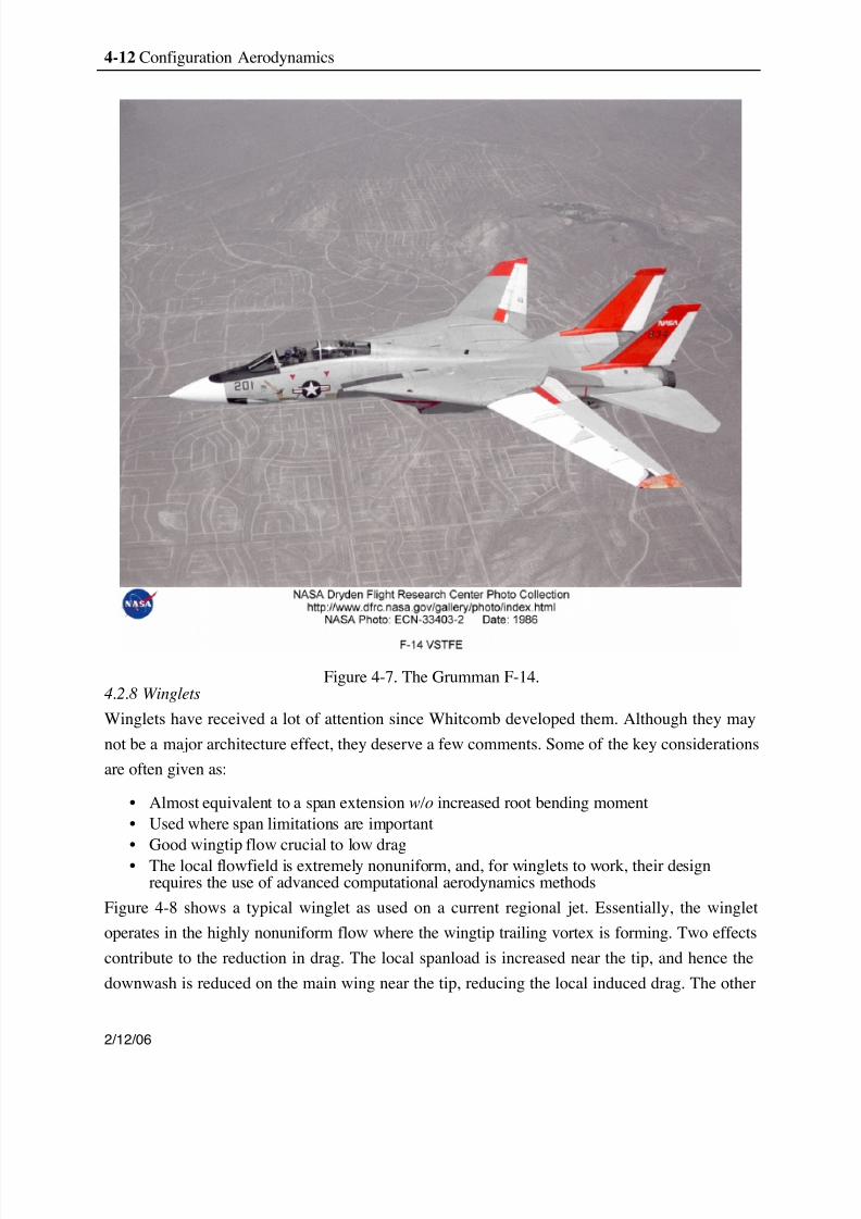
design, and is shown in Figure 4-7. Some of the pros and cons of variable sweep wings are:
• Swept back: low supersonic drag (low maximum cross-sectional area), and good“on-the-deck” ride quality (low C Lα )
• Unswept position: low landing speed (carrier suitability), efficient loiter
• Optimum sweep back available over transonic speed range• But: adds weight/complexity, currently unfashionable
Variable sweep wing aircraft design has been discussed by Kress 27 and Poison-Quinton. 28 One of
the issues in the design of variable sweep wing aircraft is the change of the aerodynamic center,
and hence the static margin, as the wing sweeps.
8/8/2019 Config a Erode Sign Opt
http://slidepdf.com/reader/full/config-a-erode-sign-opt 12/23
4-12 Configuration Aerodynamics
2/12/06
Figure 4-7. The Grumman F-14.4.2.8 Winglets
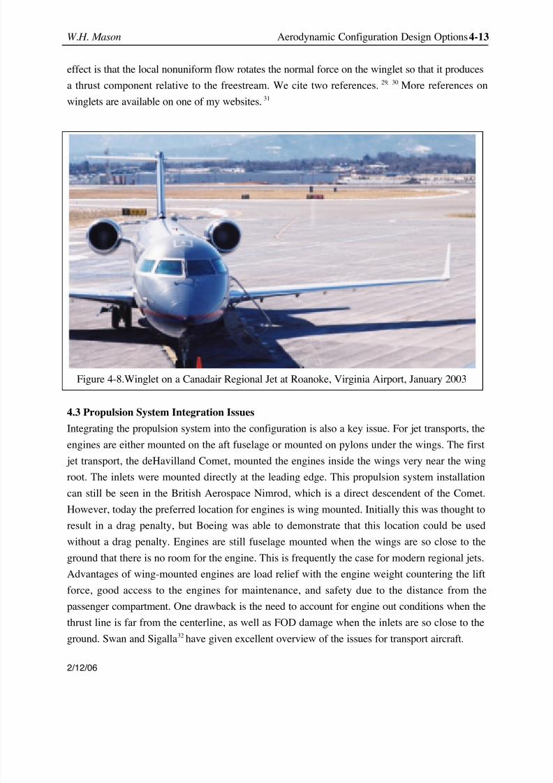
Winglets have received a lot of attention since Whitcomb developed them. Although they may
not be a major architecture effect, they deserve a few comments. Some of the key considerations
are often given as:
• Almost equivalent to a span extension w/o increased root bending moment• Used where span limitations are important• Good wingtip flow crucial to low drag• The local flowfield is extremely nonuniform, and, for winglets to work, their design
requires the use of advanced computational aerodynamics methods
Figure 4-8 shows a typical winglet as used on a current regional jet. Essentially, the winglet
operates in the highly nonuniform flow where the wingtip trailing vortex is forming. Two effects
contribute to the reduction in drag. The local spanload is increased near the tip, and hence the
downwash is reduced on the main wing near the tip, reducing the local induced drag. The other
8/8/2019 Config a Erode Sign Opt
http://slidepdf.com/reader/full/config-a-erode-sign-opt 13/23
W.H. Mason Aerodynamic Configuration Design Options 4-13
2/12/06
effect is that the local nonuniform flow rotates the normal force on the winglet so that it produces
a thrust component relative to the freestream. We cite two references. 29, 30 More references on
winglets are available on one of my websites. 31
4.3 Propulsion System Integration IssuesIntegrating the propulsion system into the configuration is also a key issue. For jet transports, the
engines are either mounted on the aft fuselage or mounted on pylons under the wings. The first
jet transport, the deHavilland Comet, mounted the engines inside the wings very near the wing
root. The inlets were mounted directly at the leading edge. This propulsion system installation
can still be seen in the British Aerospace Nimrod, which is a direct descendent of the Comet.
However, today the preferred location for engines is wing mounted. Initially this was thought to
result in a drag penalty, but Boeing was able to demonstrate that this location could be used
without a drag penalty. Engines are still fuselage mounted when the wings are so close to the
ground that there is no room for the engine. This is frequently the case for modern regional jets.
Advantages of wing-mounted engines are load relief with the engine weight countering the lift
force, good access to the engines for maintenance, and safety due to the distance from the
passenger compartment. One drawback is the need to account for engine out conditions when the
thrust line is far from the centerline, as well as FOD damage when the inlets are so close to the
ground. Swan and Sigalla 32 have given excellent overview of the issues for transport aircraft.
Figure 4-8.Winglet on a Canadair Regional Jet at Roanoke, Virginia Airport, January 2003
8/8/2019 Config a Erode Sign Opt
http://slidepdf.com/reader/full/config-a-erode-sign-opt 14/23
4-14 Configuration Aerodynamics
2/12/06
Other installations have also been used. Engines are placed above the wing on short takeoff
and landing (STOL) airplanes when the high lift system incorporates over the wing blowing,
using the engine exhaust to flow over the deflected flaps, leading to increased values of
maximum lift. Other installations are used on fighter aircraft.
4.4 Controlling the Airplane
Appropriate integration of control surfaces also requires careful consideration. Longitudinal
(pitch) control is usually the starting point, with an aft-mounted tail being the standard
configuration. Perhaps the chief consideration is controllability at high angles of attack. In
particular, when the engines are fuselage mounted, the horizontal stabilizer and elevator are
typically attached to the top of the vertical stabilizer and rudder. This is known as a T-tail
configuration. With a T-tail arrangement the horizontal tail can become immersed in the wake of
the wing at high angles of attack, resulting in the loss of effectiveness of the tail, both as a
stabilizing surface and as a control. This problem is know as pitchup, and in the worst casesituation, the plane can be caught in a high angle of attack stable trim condition known as a
“hung” or “deep stall.” The paper by Shevell and Schaufele 5 describes the redesign of the DC-9
when the crash of a BAC-111 in flight test brought this problem to the attention of commercial
transport designers. This example is discussed in more detail in Chapter 6. Military
aerodynamicists were already familiar with the problem, as a result of experiences with airplanes
like the McDonnell F-101 Voodoo. Fighter airplanes employing strakes for high lift can also
encounter hung stalls. One example is the F-16, which uses an alpha limiter in the control system
to avoid the problem. The C-17 also uses an alpha limiter in the control system.
Another aspect of the longitudinal control is the use of so-called “all flying” tails in place of
the conventional horizontal stabilizer and elevator to increase the control effectiveness. This is
especially important at high transonic and supersonic speeds. Yeager attributes the discovery of
the all-flying tail approach on the X-1 program to the eventual incorporation on the F-86 and its
subsequent outstanding high-speed performance.
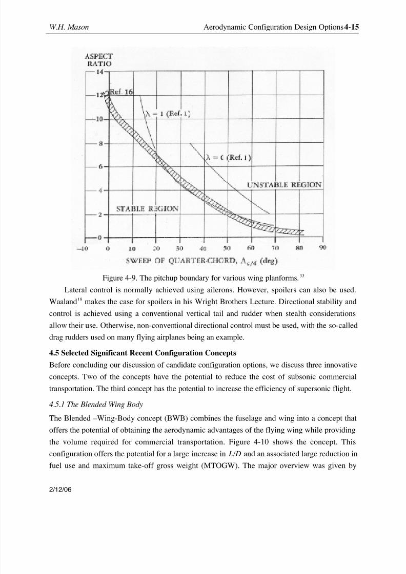
The choice of the wing planform sweep, taper and aspect ratio is also critical in establishing
the basic pitching moment characteristics. Typically, an aft swept wing stalls near the tip, and the
forward inboard portion of the wing continues to lift, leading to a change in the slope of the
pitching moment curve, and pitchup. The allowable boundaries for these parameters weredeveloped experimentally in the 1950s, and are summarized in Figure 4-9 from the USAF
DATCOM. 33 The figure provides an indication of the allowable design space, although detailed
design may allow accatable characteristics to be obtained outside the region labeled “stable”.
8/8/2019 Config a Erode Sign Opt
http://slidepdf.com/reader/full/config-a-erode-sign-opt 15/23
W.H. Mason Aerodynamic Configuration Design Options 4-15
2/12/06
Figure 4-9. The pitchup boundary for various wing planforms. 33
Lateral control is normally achieved using ailerons. However, spoilers can also be used.
Waaland 18 makes the case for spoilers in his Wright Brothers Lecture. Directional stability andcontrol is achieved using a conventional vertical tail and rudder when stealth considerations
allow their use. Otherwise, non-conventional directional control must be used, with the so-called
drag rudders used on many flying airplanes being an example.
4.5 Selected Significant Recent Configuration Concepts
Before concluding our discussion of candidate configuration options, we discuss three innovative
concepts. Two of the concepts have the potential to reduce the cost of subsonic commercial
transportation. The third concept has the potential to increase the efficiency of supersonic flight.
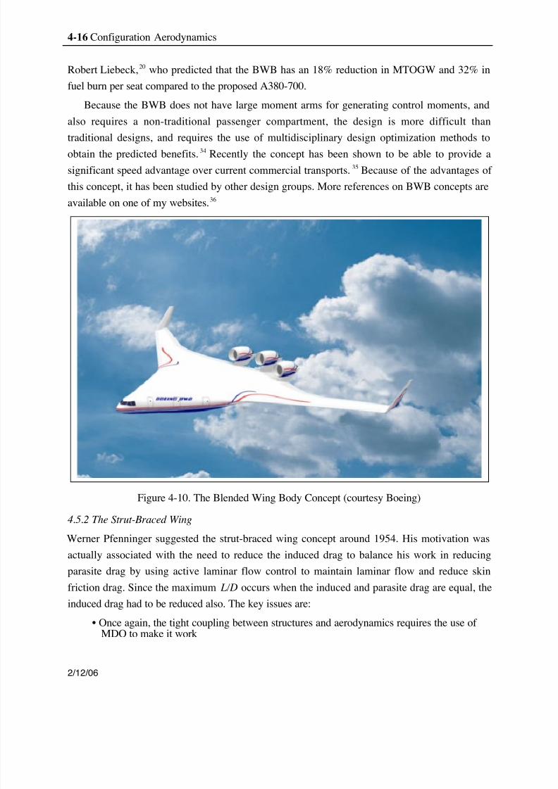
4.5.1 The Blended Wing Body
The Blended –Wing-Body concept (BWB) combines the fuselage and wing into a concept that
offers the potential of obtaining the aerodynamic advantages of the flying wing while providing
the volume required for commercial transportation. Figure 4-10 shows the concept. This
configuration offers the potential for a large increase in L/D and an associated large reduction in
fuel use and maximum take-off gross weight (MTOGW). The major overview was given by
8/8/2019 Config a Erode Sign Opt
http://slidepdf.com/reader/full/config-a-erode-sign-opt 16/23
4-16 Configuration Aerodynamics
2/12/06
Robert Liebeck, 20 who predicted that the BWB has an 18% reduction in MTOGW and 32% in
fuel burn per seat compared to the proposed A380-700.
Because the BWB does not have large moment arms for generating control moments, and
also requires a non-traditional passenger compartment, the design is more difficult than
traditional designs, and requires the use of multidisciplinary design optimization methods toobtain the predicted benefits. 34 Recently the concept has been shown to be able to provide a
significant speed advantage over current commercial transports. 35 Because of the advantages of
this concept, it has been studied by other design groups. More references on BWB concepts are
available on one of my websites. 36
Figure 4-10. The Blended Wing Body Concept (courtesy Boeing)
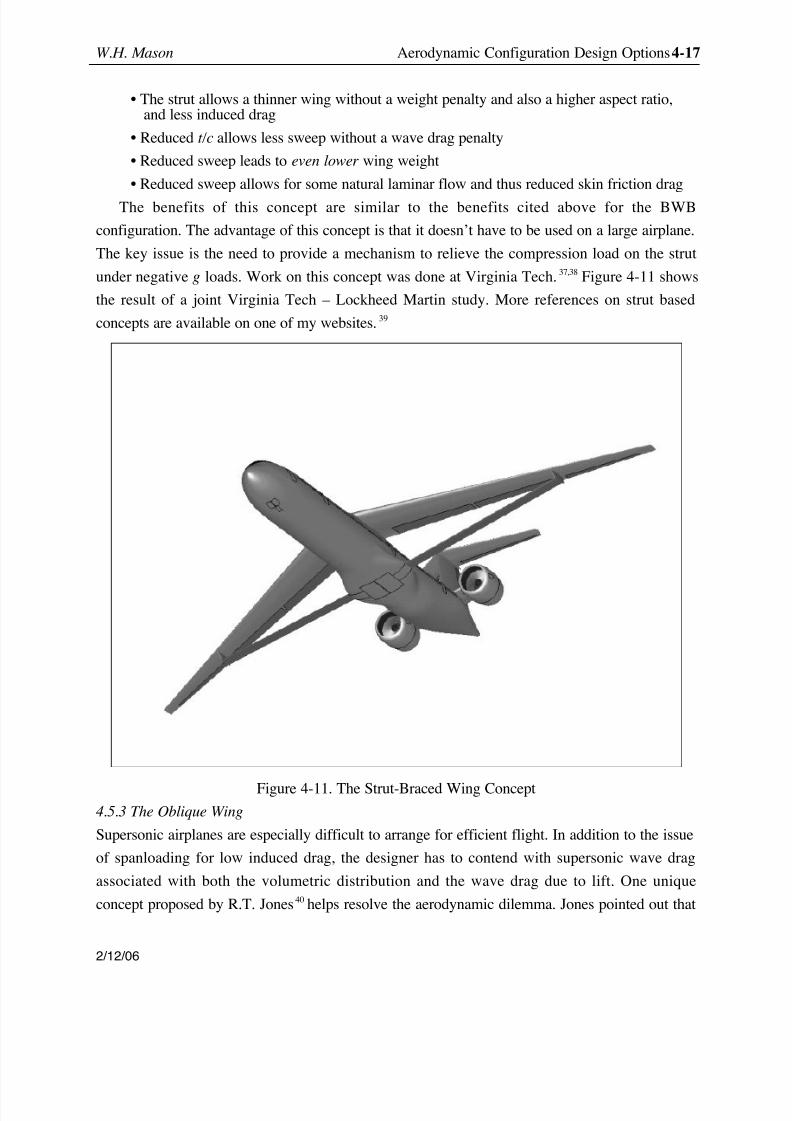
4.5.2 The Strut-Braced Wing
Werner Pfenninger suggested the strut-braced wing concept around 1954. His motivation was
actually associated with the need to reduce the induced drag to balance his work in reducingparasite drag by using active laminar flow control to maintain laminar flow and reduce skin
friction drag. Since the maximum L/D occurs when the induced and parasite drag are equal, the
induced drag had to be reduced also. The key issues are:
• Once again, the tight coupling between structures and aerodynamics requires the use of MDO to make it work
8/8/2019 Config a Erode Sign Opt
http://slidepdf.com/reader/full/config-a-erode-sign-opt 17/23
W.H. Mason Aerodynamic Configuration Design Options 4-17
2/12/06
• The strut allows a thinner wing without a weight penalty and also a higher aspect ratio,and less induced drag
• Reduced t/c allows less sweep without a wave drag penalty
• Reduced sweep leads to even lower wing weight
• Reduced sweep allows for some natural laminar flow and thus reduced skin friction drag
The benefits of this concept are similar to the benefits cited above for the BWB
configuration. The advantage of this concept is that it doesn’t have to be used on a large airplane.
The key issue is the need to provide a mechanism to relieve the compression load on the strut
under negative g loads. Work on this concept was done at Virginia Tech. 37,38 Figure 4-11 shows
the result of a joint Virginia Tech – Lockheed Martin study. More references on strut based
concepts are available on one of my websites. 39
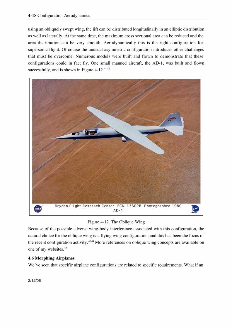
Figure 4-11. The Strut-Braced Wing Concept4.5.3 The Oblique Wing
Supersonic airplanes are especially difficult to arrange for efficient flight. In addition to the issue
of spanloading for low induced drag, the designer has to contend with supersonic wave drag
associated with both the volumetric distribution and the wave drag due to lift. One unique
concept proposed by R.T. Jones 40 helps resolve the aerodynamic dilemma. Jones pointed out that
8/8/2019 Config a Erode Sign Opt
http://slidepdf.com/reader/full/config-a-erode-sign-opt 18/23
4-18 Configuration Aerodynamics
2/12/06
using an obliquely swept wing, the lift can be distributed longitudinally in an elliptic distribution
as well as laterally. At the same time, the maximum cross sectional area can be reduced and the
area distribution can be very smooth. Aerodynamically this is the right configuration for
supersonic flight. Of course the unusual asymmetric configuration introduces other challenges
that must be overcome. Numerous models were built and flown to demonstrate that theseconfigurations could in fact fly. One small manned aircraft, the AD-1, was built and flown
successfully, and is shown in Figure 4-12. 41,42
Figure 4-12. The Oblique Wing
Because of the possible adverse wing-body interference associated with this configuration, thenatural choice for the oblique wing is a flying wing configuration, and this has been the focus of
the recent configuration activity. 43,44 More references on oblique wing concepts are available on
one of my websites. 45
4.6 Morphing Airplanes
We’ve seen that specific airplane configurations are related to specific requirements. What if an
8/8/2019 Config a Erode Sign Opt
http://slidepdf.com/reader/full/config-a-erode-sign-opt 19/23
W.H. Mason Aerodynamic Configuration Design Options 4-19
2/12/06
airplane could change its shape in flight to respond to each different flight requirement? One
example has been given above: the variable sweep wing airplane. The possibility of using
advances in structures, actuators, sensors and controls to design an airplane with significantly
increased performance by changing its shape in flight is currently the subject of considerable
interest, and is being called morphing .46
This is a true multidisciplinary design activity, and anumber of different advanced concept investigations fall within this general category, including
recent work at Virginia Tech. 47
4.7 Decision Issues
With the airplane’s mission requirements and configuration options discussed above in mind, the
designers have to choose the configuration that best satisfies the requirements. The following list
summarizes the possibilities that have to be considered:
• Should it be a canard? aft tail? tailless? three-surface? (sensitivity to cg travel?)
• Should the wings be swept? forward or aft?• Should it be a high aspect ratio, low aspect ratio, or slender wing?• What is the control concept, should it be stable or unstable?• Should thrust vectoring be used as a control? How is the propulsion system integrated?
These decisions are based on an understanding of the connection between the missionrequirements and the strengths and weaknesses of the various configuration concepts.
Knowledge of previous designs is important in making these decisions. As an example,
consider the recent JSF competition. In the 60s the services tried to design a plane to be used by
both the Air Force and Navy. The result was the F-111, which proved to be too heavy for use on
a carrier. The JSF project requires a plane for the Navy, Air Force, and Marines. The F-35 willnot be a single airframe, but will have different versions for each service. It will be interesting to
see how well this approach works.
Another example of a key design constraint is the 80-meter gate box-based span limit. The
A380 design is affected by this constraint. If you simply scale up previous Airbus designs you
discover that the wingspan would be much larger than 80 meters. So it is clear that aerodynamic
efficiency has been compromised to meet the span limit constraint.
4.8 Design Approaches
Traditional approach: Usually a matrix of concepts is defined in trying to create a final conceptto satisfy a design requirement. They are then evaluated against each other. Time is not available
to make a thorough evaluation of each design concept, and often not much detail is used.
Relatively crude approximate analyses are used and the configuration is picked. Once the
concept is selected, more detailed design studies begin.
8/8/2019 Config a Erode Sign Opt
http://slidepdf.com/reader/full/config-a-erode-sign-opt 20/23
4-20 Configuration Aerodynamics
2/12/06
At this point detailed designers (including the aerodynamicists) are given the basic design
parameters such as the wing planform (sweep, AR, etc .) and maximum t/c, etc . At this stage there
is usually limited opportunity to change the basic design parameters. The aerodynamicist defines
the detailed airfoil shapes, twist and camber, high lift system and, for supersonic aircraft, the area
ruling.M DO (Multidisciplinary Design Optimization) approach : This is a new approach to
computational design technology that seeks to use the more detailed analyses and design
methods typical of preliminary and detail design much earlier in the design process. This allows
the configuration to be defined using much more accurate information, with less uncertainty and
risk. This approach has become known as MDO. A classic example that can be addressed using
MDO is the aero-structures trade:
• A thinner wing is better for aerodynamics, worse for structures (fuel weight vs.structural weight)
• More sweep reduces transonic wave drag, increases wing weight
Numerous airplane design research studies using MDO have been done recently. We cite two
examples. 48, 49
4.9 The role of aerodynamics within the overall design process
You have to be the advocate for your discipline
• Which aerodynamic concepts are appropriate?• Consider the appropriate use and risks of advanced technology
To be effective:
• You must show the aerodynamic benefits of the configuration very clearly.• You must accommodate other team members.• You must be ready to change.
Finally, the best airplane is not the one with the highest L/D max , but most likely the one with
the lowest cost. There are many costs. Ultimately there is the life cycle cost, LCC. Other costs
are frequently the most important. Examples include the direct operating cost, DOC, and the
acquisition cost.
Once the concept is selected, many more details of the aerodynamic configuration will be
still have to be determined. After providing an overview of the role of computational
aerodynamics in the next chapter we will discuss some of these details.4.10 A concluding comment
Considering the range of configuration options discussed here, there is still room for dreamers.
We don’t yet know what the ultimate airplane concept is. Concerning the configurations
described here, all of them are appropriate in the right circumstance. There is a time and place
for everything
8/8/2019 Config a Erode Sign Opt
http://slidepdf.com/reader/full/config-a-erode-sign-opt 21/23
W.H. Mason Aerodynamic Configuration Design Options 4-21
2/12/06
4.11 Exercises
1. Read the paper on the DC-9 development by Shevell and Schaufele and discuss theirexperiences with aerodynamic pitchup.
2. Summarize the aerodynamic configuration issues for the Black Widow UAV.3. Summarize the aerodynamic configuration issues for SpaceShipOne.4. Summarize the aerodynamic configuration issues for Boomerang.5. Summarize the aerodynamic configuration issues for the low-strength sonic boom
supersonic demonstrator.
4.12 References
1 Ray Whitford, Design for Air Combat , Jane’s Information Group, 1987.2 Malcolm J. Abzug and E. Eugene Larrabee, Airplane Stability and Control , CambridgeUniversity Press, 1997.3 Daniel P. Raymer, Aircraft Design: A Conceptual Approach Third Edition , AIAA, Reston,1999. pp. 617-680.4
Jan Roskam,Airplane Design: Part II. Preliminary Configuration Design and Integration of
the Propulsion System, DARCorp., Lawrence, KS, 19865 Richard S. Shevell and Roger D. Schaufele, “Aerodynamic Design Features of the DC-9,”Journal of Aircraft , Vol. 3, No. 6, Nov-Dec 1966, pp. 515-523.6 M.L. Olason and D.A. Norton, “Aerodynamic Design Philosophy of the Boeing 737,” Journal of Aircraft , Vol. 3, No. 6, Nov-Dec 1966, pp. 524-528. (also AIAA Paper 65-739)7 Robert T. Jones, Wing Theory , Princeton University Press, Princeton, 19908 George S. Schairer, “Evolution of Modern Air Transport Wings,” in Evolution of Aircraft WingDesign , March 18-19, 1980, Dayton, Ohio, AIAA Paper 80-3037, March 1980.9 Spacht, G., “The Forward Swept Wing: A Unique Design Challenge,” AIAA Paper 80-1885,August 1980.10 Mark Moore, and Doug Frei, “X-29 Forward Swept Wing Aerodynamic Overview,” AIAAPaper 83-1834, July 1983.11 Steve Pace, The Grumman X-29 , TAB Books, Blue Ridge Summit, 199112 Rudolph Meyer and W.D. Fields (AFWAL), “Configuration Development of a SupersonicCruise Strike-Fighter,” AIAA Paper 78-148, January 1978.13 Ronald H. Hendrickson, R. Grossman, and G. Sclafani, “Design Evolution of a SupersonicCruise Strike-Fighter,” AIAA Paper 78-1452, 1978.14 Karl E. Modin and Ulf Claréus, “Aerodynamic Design Evolution of the SAAB JAS 39Grippen Aircraft,” AIAA Paper 91-3195, Baltimore, MD, Sept. 1991.15 Peter Garrison, “Go South, Young Duck,” Flying , Feb. 2000, pp 100-101.16
Northrop, J.K., “The Development of the All-Wing Aircraft,” 35th Wilbur Wright MemorialLecture, The Royal Aeronautical Society Journal , Vol. 51, pp. 481-510, 1947.17 W.R. Sears, “Flying-Wing Airplanes: The XB-35/YB-49 Program,” in Evolution of Aircraft Wing Design , March 18-19, 1980, Dayton, Ohio, AIAA Paper 80-3036, March 1980.18 Irving T. Waaland, “Technology in the Lives of an Aircraft Designer,” AIAA Wright BrothersLecture, Sept., 199119 W.H. Mason, “Flying Wings including the B-2,”http://www.aoe.vt.edu/~mason/Mason/ACiFlyWngs.html
8/8/2019 Config a Erode Sign Opt
http://slidepdf.com/reader/full/config-a-erode-sign-opt 22/23
4-22 Configuration Aerodynamics
2/12/06
20 Robert H. Liebeck, “Design of the Blended-Wing-Body Subsonic Transport,” AIAA paper2002-0002, 2002 Wright Brothers Lecture, January 2002.21 J.W. Agnew, and J.R. Hess, Jr., “Benefits of the Aerodynamic Interaction to the Three SurfaceConfiguration,” AIAA Paper 79-1830, August 1979.22
J.W. Agnew, G.W. Lyerla, and S.B. Grafton, “The Linear and Non-linear aerodynamics of Three-Surface Aircraft Concepts,” AIAA Paper 80-1581, 1980.23 ._,“Piaggio Avanti, Beech Starship Offer Differing Performance Characteristics,” Av. Wk. &Sp. Tech ., Oct 2, 1989, pp75-78.24 Roskam’s Airplane War Stories , DARcorp., Lawrence, KS, 2002, pp. 194-198.25 E.C. Polhamus, “Applying Slender Wing Benefits to Military Aircraft,” AIAA WrightBrothers lecture, Journal of Aircraft , Vol. 21, No. 6, August 1984, pp. 545-559.26 Ph. Poisson-Quinton, “Slender Wings for Civil and Military Aircraft,” Eighth Theodore vonKármán Memorial Lecture , Israel Journal of Technology , Vol. 16, No. 3, 1978, pp. 97-131.27 Robert W. Kress, “Variable Sweep Wing Design,” in Evolution of Aircraft Wing Design ,March 18-19, 1980, Dayton, Ohio, AIAA Paper 80-3043, 1980.28 Poison-Quinton, P., “Aerodynamics of variable sweep,” in
Assessment of Lift Augmentation
Devices , AGARD-LS-43-71, Aug. 1970 (71N20054)29 James F. Marchman III, H. F. Faery, Jr., and D. Manor, “Whitcomb Winglet Applications toGeneral Aviation Aircraft,” AIAA Paper 78-1478, August 1978.30 Ilan Kroo, “Drag Due to Lift: Concepts for Prediction and Reduction,” Annual Review of Fluid Mechanics , Vol. 33, 2001, pp. 587-617.31 W.H. Mason, “Winglet Aerodynamics (including tip sails),”http://www.aoe.vt.edu/~mason/Mason/AeroWinglets.html32 Walter C. Swan and Armand Sigalla, “The Problem of Installing a Modern High BypassEngine on a Twin Jet Transonic Transport,” in Aerodynamic Drag , AGARD CP-124, April
1973.33 Hoak, D.E., et al, “USAF Stability and Control DATCOM,” Flight Control Division, AirForce Flight Dynamics Laboratory, WPAFB, Ohio, 45433-0000, 1978.34 Sean Wakayama, “Multidisciplinary Design Optimization of the Blended-Wing-Body,” AIAAPaper 98-4938, Sept. 199835 Dino Roman, Richard Gilmore and Sean Wakayama, “Aerodynamics of High-SubsonicBlended-Wing-Body Configurations,” AIAA Paper 2003-0554, Jan. 2003.36 W.H. Mason, “Blended Wing-Body Concept,”http://www.aoe.vt.edu/~mason/Mason/ACiADblended.html37 Grasmeyer, J.M., Naghshineh, A., Tetrault, P.-A., Grossman, B., Haftka, R.T., Kapania, R.K.,Mason, W.H., Schetz, J.A., “Multidisciplinary Design Optimization of a Strut-Braced WingAircraft with Tip-Mounted Engines,” MAD Center Report MAD 98-01-01, January 1998.38 J.F. Gundlach, P.-A. Tetrault, F.H. Gern, , A. Naghshineh-Pour, A. Ko, J.A. Schetz, W.H.Mason, B. Grossman. R.K. Kapania, and R.T. Haftka, “Multidisciplinary Design Optimization of a Strut-Braced Transonic Transport,” AIAA 36th Aerospace Sciences Meeting and Exhibit,Reno, NV, AIAA Paper 2000-0420, Jan. 200039 W.H. Mason, “Strut and Truss-Braced Wing Concepts,”http://www.aoe.vt.edu/~mason/Mason/ACiADtbw.html40 Robert T. Jones and James W. Nisbet, “Transonic Transport Wings-Oblique or Swept?”
8/8/2019 Config a Erode Sign Opt
http://slidepdf.com/reader/full/config-a-erode-sign-opt 23/23
W.H. Mason Aerodynamic Configuration Design Options 4-23
Astronautics and Aeronautics , Jan. 1974, pp. 40-47. They really mean supersonic transports, butcouldn't say so.41 T.C. Mcmurty, A.G. Sim, and W. H. Andrews, “AD-1 Oblique Wing Aircraft Program,”AIAA Paper 81-2354, Nov., 198142
R.E Curry, and A.G. Sim, “Unique Flight Characteristics of the AD-1 Oblique-Wing ResearchAirplane,” AIA Paper 82-1329, Aug. 1982.43 Alex J. M. ven der Velden and E. Torebeek, “Design of a Small Supersonic Oblique- WingTransport Aircraft,” Journal of Aircraft , Vol. 26, No. 3, Mar. 1989, pp.193-197.44 Richard Seebass, “Oblique Flying Wing Studies,” New Design Concepts for High Speed Transport , edited by H. Sobieczky, CISM Courses and Lectures, Vol. 366, Springer-Verlag,Vienna/New York, 1997, pp. 317-336.45 W. H. Mason, “Oblique Wing Concepts,”http://www.aoe.vt.edu/~mason/Mason/ACiADoblique.html46 R.W. Wlezien, G.C. Horner, A. R. McGowan, S.L. Padula, M. A. Scott, R. J. Silcox, and J. O.Simpson, “The Aircraft Morphing Program,” AIAA Paper 98-1927, April 1998.
47 C. O. Johnston, D. A. Neal, L. D. Wiggins. H.H. Robertshaw, W.H. Mason and D.J. Inman,“A Model to Compare the Flight Control Energy Requirements of Morphing and ConventionallyActuated Wings, ” 11th AIAA/ASME/AHS Adaptive Structures Conference, Norfolk, VA, AIAAPaper 2003-1716, 7-10 April 200348 Natalia M. Alexandrov and M.Y. Hussaini, editors, Multidisciplinary Design Optimization:State of the Art , SIAM, Philadelphia, 199749 Giunta, A.A., Golovidov, O., Knill, D.L., Grossman, B., Mason, W.H., Watson, L.T., andHaftka, R.T., “Multidisciplinary Design Optimization of Advanced Aircraft Configurations,”Fifteenth International Conference on Numerical Methods in Fluid Dynamics, P. Kutler, J.Flores, J.-J. Chattot, Eds., in Lecture Notes in Physics, Vol. 490, Springer-Verlag, Berlin, 1997,pp. 14-34.
Related Documents