CONFIDENTIAL Application for Certification - Part 1 Volume 1 [ Common Information ] 2014 Model Year For Outlander Sport (RVR) 2.0L Response Requested by : May 9, 2013 (for EPA) May 16, 2013 (for ARB) For Lancer, Lancer Sportback 2.0L & 2.4L Response Requested by : March 14, 2013 (for EPA) March 21, 2013 (for ARB) For Lancer Evolution, Lancer, Lancer Sportback 2.0L Response Requested by : March 14, 2013 (for EPA) March 21, 2013 (for ARB) For Outlander 2.4L Response Requested by : March 14, 2013 (for EPA) March 21, 2013 (for ARB) For Outlander 3.0L Response Requested by : March 14, 2013 (for EPA) March 21, 2013 (for ARB) For MIRAGE 1.2L Response Requested by : December 13, 2012 (for EPA) December 20, 2012 (for ARB) For Questions, Contact : David Patterson, MRDA-CYP (TEL) 714 372-6000, (FAX) 714 372-6243 $ Issue Date : 11-12-2012 Revised Date : 02-07-2013, 04-04-2013, 12-19-2013 $

Welcome message from author
This document is posted to help you gain knowledge. Please leave a comment to let me know what you think about it! Share it to your friends and learn new things together.
Transcript

CONFIDENTIAL
Application for Certification - Part 1
Volume 1 [ Common Information ]
2014 Model Year
For Outlander Sport (RVR) 2.0LResponse Requested by : May 9, 2013 (for EPA)
May 16, 2013 (for ARB)
For Lancer, Lancer Sportback 2.0L & 2.4LResponse Requested by : March 14, 2013 (for EPA)
March 21, 2013 (for ARB)
For Lancer Evolution, Lancer, Lancer Sportback 2.0LResponse Requested by : March 14, 2013 (for EPA)
March 21, 2013 (for ARB)
For Outlander 2.4L Response Requested by : March 14, 2013 (for EPA)
March 21, 2013 (for ARB)
For Outlander 3.0L Response Requested by : March 14, 2013 (for EPA)
March 21, 2013 (for ARB)
For MIRAGE 1.2L Response Requested by : December 13, 2012 (for EPA)
December 20, 2012 (for ARB)
For Questions, Contact :David Patterson, MRDA-CYP (TEL) 714 372-6000, (FAX) 714 372-6243 $
Issue Date : 11-12-2012Revised Date : 02-07-2013, 04-04-2013, 12-19-2013 $

2014 MY Application for Certification
File Name : Volume 1 Common InformationTest Group : ALL
Section No. Content Volume00.00.00 Preface 101.00.00 Correspondence and Communications 102.00.00 Durability Group Description 1, 203.00.00 Evaporative/ Refueling Family Description 104.00.00 Durability Procedure Description 1, 205.00.00 Test Group Description 1, 2, 306.00.00 Test Vehicle Description 307.00.00 Test Results 308.00.00 Emission Testing Waiver Statement 109.00.00 OBD System Description 210.00.00 Description of Alternate-fueled Vehicles 111.00.00 AECD Description 1, 212.00.00 Description of Vehicles Covered by Certificate and Test Parameters 1, 313.00.00 Projected Sales / Actual Sales 1, 214.00.00 Request for Certificate 315.00.00 Other Information 1, 316.00.00 Notice of Confidential Information 117.00.00 California ARB Information 1, 2, 318.00.00 References 2

'14MY
PREFACE
A. Test Group
Model Name Test Group Emission Sales AreaStandard
MIRAGE EMTXV01.2GRB Tier 2 Bin 5 50-StatesLEV II LEV
Lancer EMTXV02.4GRB Tier 2 Bin 5 50-StatesLEV II LEV
Lancer Sportback
Lancer Evolution EMTXV02.0GRB Tier 2 Bin 5 50-StatesLEV II LEV
Lancer
Lancer Sportback
Outlander Sport EMTXT02.0GR4 Tier 2 Bin 5 50-States $(RVR) LEV II ULEV
Outlander EMTXT02.4GR4 Tier 2 Bin 5 50-StatesLEV II ULEV
Outlander EMTXT02.4GR2 Tier 2 Bin 5 50-StatesLEV II ULEV
Outlander EMTXT03.0GRB Tier2 Bin 5 CanadaLEV II LEV
Outlander EMTXT03.0GR4 Tier 2 Bin 5 50-StatesLEV II ULEV
Issue Date : 11-12-2012Revised Date : 02-07-2013, 04-04-2013 $
00.00-1

'14MY
B. Emission Control System Acronyms
AIS : Auto Idle Speed (motor)A/F Sensor : Air Fuel Ration SensorAFS : Air Flow SensorAPS : Accelerator Pedal Position SensorBPS : Barometric Pressure SensorCAC : Charge Air CoolerCAN : Evap. Canister or Controller Area NetworkCAS : Crank Angle SensorC.C : Catalytic Converter CPS : Cam Position SensorCVT : Continuously Variable TransmissionDOHC : Double Over Head CamshaftDOR : Direct Ozone ReductionECM : Engine Control ModuleECTS : Engine Coolant Temperature SensorEET : Electric EGR TransducerEGR : Exhaust Gas RecirculationESC : Electronic Spark Control IgniterESS : Engine Speed SensorETV : Electronic Throttle ValveFLICS : Flow Limited Idle Speed Control SystemFLS : Fuel Level SensorFTPS : Fuel Tank Pressure SensorFTS : Fuel Temperature SensorHAFS : Heated Air Fuel Ratio SensorHC Adsorber TWC : Hydrocarbon Adsorber Three Way Catalytic ConverterHO2S : Heated Oxygen SensorIAC : Idle Air Control (Valve)IAT : Intake Air TemperatureISC : Idle Speed ControlL4 : Automatic/Four-Speed (Lock-Up)M5 : Manual/Five SpeedM6 : Manual/Six SpeedMAP : Manifold Absolute PressureMIVEC : Mitsubishi Innovative Valve Timing & Lift Electronic Control System
(2-Cam Profile System)MIVEC+ : Mitsubishi Innovative Valve Timing Electronic Control System
(Variable Valve Timing System with both inlet and exhaust)MIVEC- : Mitsubishi Innovative Valve Timing Electronic Control System
(Variable Valve Timing System with inlet)MIVEC2 : Mitsubishi Innovative Valve Timing Electronic Control System
(Continuous Variable Valve Timing System with inlet and Variable Valve Timing System with exhaust)
Issue Date : 11-12-2012Revised Date :
00.00-2

'14MY
B. Emission Control System Acronyms (continued)
OBD II : On-board Diagnostic II SystemOCV : Oil Control Valve (MIVEC)O/P SW : Oil Pressure Switch (MIVEC)PCM : Powertrain Control Module PCV : Purge Control ValvePCVV : Positive Crankcase Ventilation ValveS4 : Automatic/Four-Speed (Lock-Up) with Manual Shift ModeS5 : Automatic/Five-Speed (Lock-Up) with Manual Shift ModeS6 : Automatic/Six-Speed (Lock-Up) with Manual Shift ModeS-CVT : Continuously Variable Transmission with Manual Shift ModeSCI : Serial Communication InterfaceSFI : Sequential Multiport Electronic Fuel InjectionSOHC : Single Over Head CamshaftTC : TurbochargerTCL : Traction ControlTCM : Transmission Control ModuleTDC : Top Dead Center (Sensor)TPS : Throttle Position SensorTWC : Three Way Catalytic ConverterVCV : Vacuum Controlled ValveVIS : Variable Induction SystemVVT : Variable Valve Timing SystemWU-TWC : Warm Up Three Way Catalytic ConverterW/G : Waste Gate5SST : Automatic/Five-Speed (Dual Clutch) with Manual Shift Mode6SST : Automatic/Six-Speed (Dual Clutch) with Manual Shift Mode
Issue Date : 11-12-2012Revised Date :
00.00-3

'14MY
01.00.00 CORRESPONDENCE AND COMMUNICATIONS
01.01.00 Certification Information
1. Corporate Name that appears on the Certificate(s) of Conformity / Executive Order(s)
Mitsubishi Motors Corporation
2. Responsible Official
(1) MRDA-Cypress TEL : 714-372-6000, FAX : 714-372-6243 $ / Responsibility : All areas of emission certification related to California ARB
* David Patterson : Chief Engineer [email protected]
(2) MRDA-Ann Arbor Lab. TEL : 734-971-0900, FAX : 734-971-0901 $ / Responsibility : Overall emission certification
Hayami Nakagawa : Director [email protected] $
(3) Okazaki Office (Japan) TEL : 0564-32-5281, FAX : 0564-33-1202 $Certification and Regulation Compliance Department
/ Responsibility : Overall emission certification
* Tomonobu Sakagami : Manager [email protected] (Authorized Representative Applicant)
* : Primary contact person at each branch office
Issue Date : 11-12-2012Revised Date : 12-19-2013 $
01.00-1

'14MY
3. Addressee of the Certificate(s) of Conformity
David PattersonChief Engineer
Mitsubishi Motors R & D of America, Inc.(MRDA) $Cypress Office6400 W. Katella Ave.Cypress, California 90630U.S.A.
Telephone Number : 714-372-6000 $Fax Number : 714-372-6243 $
4. Addressee of the Executive Order(s)
David PattersonChief Engineer
Mitsubishi Motors R & D of America, Inc.(MRDA) $Cypress Office6400 W. Katella Ave.Cypress, California 90630U.S.A.
Telephone Number : 714-372-6000 $Fax Number : 714-372-6243 $
Issue Date : 11-12-2012Revised Date : 12-19-2013 $
01.00-2

'14MY
02.00.00 DURABILITY GROUP DESCRIPTION
02.01.00 Breakdown of Durability Group
E MTX G P G N N JA1
Character 10 thru. 12 Catalyst CodeSee Vol.2-1 Sec.02.02.00
Character 9 Third Fuel usedN : Not Applicable
Character 8 Second Fuel usedN : Not Applicable E : Battery Electric
Character 7 Primary Fuel usedG : Gasoline E : Battery Electric
Character 6 Engine TypeP : Piston E : Battery ElectricH : Hybrid Electric
Character 5 Combustion CycleG : Otto Cycle - Four StrokeE : Battery ElectricH : Hybrid EV with Otto Cycle 4 Stroke
Character 2 thru. 4 Manufacturer CodeMTX : MMC DSX : MMNA
Character 1 Model YearE : 2014
02.02.00 Durability Group Description
See Vol.2-1 (Section 02.02.00)
Issue Date : 11-12-2012Revised Date :
02.00-1

'14MY
03.00.00 EVAPORATIVE / REFUELING FAMILY DESCRIPTION
03.01.00 Breakdown of Evap. / Refueling Family
E MTX R 0078 A 1 F
Character 12 Wild Card
Character 11 Evap. Standard1 : Federal LEV II / LEV II Evap.2 : Zero Evap.
Character 10 Canister Config. Purge ControlA : Plastic Housing- Closed Bottom-
Purge Controlled
Character 6 thru. 9 Canister Working Capacity(g)
Character 5 Evap. FamilyR : Evap. / ORVR System
Character 2 thru. 4 Manufacturer CodeMTX : MMC DSX : MMNA
Character 1 Model YearE : 2014
Issue Date : 11-12-2012Revised Date :
03.00-1

'14MY
03.02.00 Evap. / Refueling Family : EMTXR0078A1F (Federal LEV II / LEV II Evap.)
Parameter Description
(1) Type of Vapor Storage Device Evaporative Canister(2) Basic Canister Design
(i) Working Capacity 78 g(ii) System Configuration 1 canister(iii) Geometry Construction
Type : Dual Carbon BedsTotal Carbon Volume : 1.4 L
Activated Carbon : (MAIN) BAX1100(SUB) BAXLBE
(iv) Materials Plastic(3) Fuel System SFI(4) Type of Refueling Emission Integrated with Evaporative Control System
Control System(5) Fill Pipe Seal Mechanism Liquid Seal(6) Valve :
2 Way Valve for Overfill LimiterLeveling Valve for Overfill LimiterFuel Cut-off Valve for Rollover Protection and Vapor ReliefCanister Vent Valve N/A1 Way Check Valve N/AFuel Shut-off Valve for Spit Back
(7) Solenoid Valve :Evap. Purge Solenoid Valve to control Airflow in the Purge Solenoid ValveCanister Vent Solenoid Valve to close the Whole Evaporative System
for Evaporative System Monitor (OBD II)(8) Vapor Hose Material Metal, Rubber and Plastic(9) Fuel Tank Material Plastic
Issue Date : 11-12-2012Revised Date :
03.02-1
Vent Port
Main Carbon Bed Sub Carbon Bed
Purge PortVapor Port Vent Port
Main Carbon Bed Sub Carbon Bed
Purge PortVapor Port

'14MY
03.02.00 Evap. / Refueling Family : EMTXR0135A1D (Federal LEV II / LEV II Evap.)
Parameter Description
(1) Type of Vapor Storage Device Evaporative Canister(2) Basic Canister Design
(i) Working Capacity 135 g(ii) System Configuration 1 canister(iii) Geometry Construction
Type : Dual Carbon BedsTotal Carbon Volume : 2.1 L
Activated Carbon : (MAIN) BAX1500(SUB) BAXLBE
(iv) Materials Plastic(3) Fuel System SFI(4) Type of Refueling Emission Integrated with Evaporative Control System
Control System(5) Fill Pipe Seal Mechanism Liquid Seal(6) Valve :
2 Way Valve for Overfill LimiterLeveling Valve for Overfill LimiterFuel Cut-off Valve for Rollover Protection and Vapor ReliefCanister Vent Valve N/A1 Way Check Valve N/AFuel Shut-off Valve for Spit Back
(7) Solenoid Valve :Evap. Purge Solenoid Valve to control Airflow in the Purge Solenoid ValveCanister Vent Solenoid Valve to close the Whole Evaporative System
for Evaporative System Monitor (OBD II)(8) Vapor Hose Material Metal, Rubber and Plastic(9) Fuel Tank Material Metal
Issue Date : 02-07-2013Revised Date :
03.02-2
Vent Port
Main Carbon Bed Sub Carbon Bed
Purge PortVapor Port

'14MY
03.02.00 Evap. / Refueling Family : EMTXR0135A1C (Federal LEV II / LEV II Evap.)
Parameter Description
(1) Type of Vapor Storage Device Evaporative Canister(2) Basic Canister Design
(i) Working Capacity 135 g(ii) System Configuration 1 canister(iii) Geometry Construction
Type : Dual Carbon BedsTotal Carbon Volume : 2.1 L
Activated Carbon : (MAIN) BAX1500(SUB) BAXLBE
(iv) Materials Plastic(3) Fuel System SFI(4) Type of Refueling Emission Integrated with Evaporative Control System
Control System(5) Fill Pipe Seal Mechanism Liquid Seal(6) Valve :
2 Way Valve for Overfill LimiterLeveling Valve for Overfill LimiterFuel Cut-off Valve for Rollover Protection and Vapor ReliefCanister Vent Valve N/A1 Way Check Valve N/AFuel Shut-off Valve for Spit Back
(7) Solenoid Valve :Evap. Purge Solenoid Valve to control Airflow in the Purge Solenoid ValveCanister Vent Solenoid Valve to close the Whole Evaporative System
for Evaporative System Monitor (OBD II)(8) Vapor Hose Material Metal, Rubber and Plastic(9) Fuel Tank Material Metal
Issue Date : 02-07-2013Revised Date :
03.02-3
Main Carbon Bed Sub Carbon Bed
Vent PortPurge Port
Vapor Port

'14MY
04.00.00 DURABILITY PROCEDURE DESCRIPTION
04.01.00 Exhaust Durability Procedures
04.01.01 Exhaust Durability Procedure (ASADP/ADP)
See Vol.2-1 (Section 04.01.02)
Issue Date : 11-12-2012Revised Date :
04.00-1

'14MY
04.02.00 Exhaust Emission Deterioration Factors (derived from ADP)
Test Group : EMTXV01.2GRBDurability Group : EMTXGPGNNJA1
Test DataVehicle I.D. No.: EB14-LD2A
Actual NMHC NMOG CO NOxSystem Mile (g/mile) (g/mile) (g/mile) (g/mile)
4007 # 0.03287 0.03418 0.28417 0.017164065 ## 0.03068 0.03191 0.24893 0.012514083 ### 0.03013 0.03134 0.22686 0.01808
120000 # 0.03705 0.03853 0.34197 0.03005120019 ## 0.03522 0.03663 0.30256 0.04046120037 ### 0.03650 0.03796 0.31435 0.03703
# : 1st test## : 2nd test
### : 3rd test
Calculated Emissions :NMHC NMOG CO NOx(g/mile) (g/mile) (g/mile) (g/mile)
4,000-mile 0.03122 0.03247 0.25330 0.0159150,000-mile 0.03322 0.03455 0.27959 0.02381
120,000-mile 0.03626 0.03771 0.31961 0.03584Deterioration Factor for 50K 0.0020 0.0021 0.03 0.008
Deterioration Factor for 120K 0.0050 0.0052 0.07 0.020Note) Additive DFs for both 50K and 120K are applied.
SFTP DF comes from FTP DF.
Issue Date : 11-12-2012Revised Date :
04.02-1

'14MY
04.02.00 Exhaust Emission Deterioration Factors (derived from ADP)
Test Group : EMTXV02.4GRBDurability Group : EMTXGPGNNAT2
Test DataVehicle I.D. No.: EB11-DB5B
Actual NMHC NMOG CO NOxSystem Mile (g/mile) (g/mile) (g/mile) (g/mile)
4093 # 0.02888 0.03004 0.31492 0.017804149 ## 0.02515 0.02616 0.33150 0.018094168 ### 0.02417 0.02514 0.31791 0.01598
120000 # 0.03761 0.03911 0.53973 0.03601120019 ## 0.03504 0.03644 0.49760 0.03571120037 ### 0.03956 0.04114 0.64764 0.03638
# : 1st test## : 2nd test
### : 3rd test
Calculated Emissions :NMHC NMOG CO NOx(g/mile) (g/mile) (g/mile) (g/mile)
4,000-mile 0.02605 0.02710 0.32115 0.0172750,000-mile 0.03055 0.03178 0.41651 0.02471
120,000-mile 0.03740 0.03890 0.56162 0.03603Deterioration Factor for 50K 0.0045 0.0047 0.10 0.007
Deterioration Factor for 120K 0.0113 0.0118 0.24 0.019Note) Additive DFs for both 50K and 120K are applied.
SFTP DF comes from FTP DF.This test group is carried over from a previous model year.
Issue Date : 02-07-2013Revised Date :
04.02-2

'14MY
04.02.00 Exhaust Emission Deterioration Factors (derived from ADP)
Test Group : EMTXV02.0GRBDurability Group : EMTXGPGNNBR1
Test DataVehicle I.D. No.: EB11-CA73
Actual NMHC NMOG CO NOxSystem Mile (g/mile) (g/mile) (g/mile) (g/mile)
3979 # 0.03085 0.03208 0.66249 0.020924035 ## 0.03142 0.03268 0.67300 0.021844054 ### 0.03140 0.03266 0.71980 0.02198
120000 # 0.04382 0.04557 0.80197 0.03946120017 ## 0.04666 0.04853 0.98301 0.03890120036 ### 0.04599 0.04783 0.96865 0.03527
# : 1st test## : 2nd test
### : 3rd test
Calculated Emissions :NMHC NMOG CO NOx(g/mile) (g/mile) (g/mile) (g/mile)
4,000-mile 0.03122 0.03247 0.68504 0.0215850,000-mile 0.03688 0.03835 0.77736 0.02804
120,000-mile 0.04549 0.04731 0.91785 0.03787Deterioration Factor for 50K 0.0057 0.0059 0.09 0.006
Deterioration Factor for 120K 0.0143 0.0148 0.23 0.016Note) Additive DFs for both 50K and 120K are applied.
SFTP DF comes from FTP DF.This test group is carried over from a previous model year.
Issue Date : 02-07-2013Revised Date :
04.02-3
'14MY
04.02.00 Exhaust Emission Deterioration Factors (derived from ADP)
Test Group : EMTXT02.4GR4, EMTXT02.4GR2Durability Group : EMTXGPGNNAU1
Test DataVehicle I.D. No.: EB14-RB2A
Actual NMHC NMOG CO NOxSystem Mile (g/mile) (g/mile) (g/mile) (g/mile)
4015 # 0.02094 0.02178 0.41233 0.012494072 ## 0.02010 0.02090 0.35134 0.018444089 ### 0.02011 0.02091 0.42124 0.01595
120000 # 0.03091 0.03215 0.84269 0.03281120018 ## 0.03170 0.03297 0.98971 0.03732120036 ### 0.03245 0.03375 1.13592 0.03816
# : 1st test## : 2nd test
### : 3rd test
Calculated Emissions :NMHC NMOG CO NOx(g/mile) (g/mile) (g/mile) (g/mile)
4,000-mile 0.02038 0.02119 0.39466 0.0156250,000-mile 0.02486 0.02586 0.63049 0.02374
120,000-mile 0.03168 0.03295 0.98936 0.03609Deterioration Factor for 50K 0.0045 0.0047 0.24 0.008
Deterioration Factor for 120K 0.0113 0.0118 0.59 0.020Note) Additive DFs for both 50K and 120K are applied.
SFTP DF comes from FTP DF.
Issue Date : 02-07-2013Revised Date :
04.02-4

'14MY
04.02.00 Exhaust Emission Deterioration Factors (derived from ADP)
Test Group : EMTXT03.0GRBDurability Group : EMTXGPGNNEA1
Test DataVehicle I.D. No.: EF14-RC21
Actual NMHC NMOG CO NOxSystem Mile (g/mile) (g/mile) (g/mile) (g/mile)
3964 # 0.03159 0.03285 0.36602 0.004664020 ## 0.02581 0.02684 0.32199 0.003304039 ### 0.02981 0.03100 0.37575 0.00397
120000 # 0.05684 0.05911 0.88997 0.01041120018 ## 0.05751 0.05981 0.91925 0.01237120037 ### 0.05475 0.05694 0.90174 0.01361
# : 1st test## : 2nd test
### : 3rd test
Calculated Emissions :NMHC NMOG CO NOx(g/mile) (g/mile) (g/mile) (g/mile)
4,000-mile 0.02907 0.03023 0.35455 0.0039850,000-mile 0.03989 0.04149 0.57226 0.00721
120,000-mile 0.05636 0.05862 0.90357 0.01213Deterioration Factor for 50K 0.0108 0.0113 0.22 0.003
Deterioration Factor for 120K 0.0273 0.0284 0.55 0.008Note) Additive DFs for both 50K and 120K are applied.
SFTP DF comes from FTP DF.
Issue Date : 02-07-2013Revised Date :
04.02-5

'14MY
04.02.00 Exhaust Emission Deterioration Factors (derived from ADP)
Test Group : EMTXT03.0GR4Durability Group : EMTXGPGNNEA2
Test DataVehicle I.D. No.: EB14-RC23
Actual NMHC NMOG CO NOxSystem Mile (g/mile) (g/mile) (g/mile) (g/mile)
4012 # 0.01593 0.01657 0.31444 0.001244044 ## 0.01382 0.01437 0.23186 0.002084079 ### 0.01550 0.01612 0.29953 0.00177
120000 # 0.02025 0.02106 0.55992 0.00397120018 ## 0.02145 0.02231 0.60922 0.00397120037 ### 0.02335 0.02428 0.59224 0.00423
# : 1st test## : 2nd test
### : 3rd test
Calculated Emissions :NMHC NMOG CO NOx(g/mile) (g/mile) (g/mile) (g/mile)
4,000-mile 0.01508 0.01568 0.28182 0.0017050,000-mile 0.01770 0.01841 0.40287 0.00263
120,000-mile 0.02168 0.02255 0.58708 0.00406Deterioration Factor for 50K 0.0026 0.0027 0.12 0.001
Deterioration Factor for 120K 0.0066 0.0069 0.31 0.002Note) Additive DFs for both 50K and 120K are applied.
SFTP DF comes from FTP DF.
Issue Date : 02-07-2013Revised Date :
04.02-6

'14MY
04.02.00 Exhaust Emission Deterioration Factors (derived from ADP)
Test Group : EMTXT02.0GR4Durability Group : EMTXGPGNNAU2
Test DataVehicle I.D. No.: EB14-RB2A
Actual NMHC NMOG CO NOxSystem Mile (g/mile) (g/mile) (g/mile) (g/mile)
4015 # 0.02094 0.02178 0.41233 0.012494072 ## 0.02010 0.02090 0.35134 0.018444089 ### 0.02011 0.02091 0.42124 0.01595
120000 # 0.03091 0.03215 0.84269 0.03281120018 ## 0.03170 0.03297 0.98971 0.03732120036 ### 0.03245 0.03375 1.13592 0.03816
# : 1st test## : 2nd test
### : 3rd test
Calculated Emissions :NMHC NMOG CO NOx(g/mile) (g/mile) (g/mile) (g/mile)
4,000-mile 0.02038 0.02119 0.39466 0.0156250,000-mile 0.02486 0.02586 0.63049 0.02374
120,000-mile 0.03168 0.03295 0.98936 0.03609Deterioration Factor for 50K 0.0045 0.0047 0.24 0.008
Deterioration Factor for 120K 0.0113 0.0118 0.59 0.020Note) Additive DFs for both 50K and 120K are applied.
SFTP DF comes from FTP DF.
Issue Date : 04-04-2013Revised Date :
04.02-7

'14MY
04.03.00 Evaporative System Durability Procedure
For 150K
Applicable : All Models
This procedure meets the requirements of Part ll. Section A. of the California EvaporativeEmission Standards and Test Procedures for 2001 and Subsequent Model Motor Vehicles(adopted 8/5/1999).
(1) The vehicle evaporative emission deterioration factor is defined by all valid evaporativeemission data from the durability data vehicles tests, within each California evaporative emissionfamily. If the deterioration factor is less than zero, the factor is set as zero.
(2) The averages of all four tests (using bench aged components) at 4,000-mile and at 150,000-mileon the stabilized vehicle are used in the following formula to determine a bench aged evaporativeemission deterioration factor (DFB).
DFB = ((Evap. average @ 150K miles) - (Evap. average @ 4K miles)) gHC/test
In the case of negative values,the factor is reported as zero.
(3) Certification Deterioration Factor (additive) :The evaporative emissions deterioration factor for the purpose of California ARB certification isdetermined by averaging the bench aged evaporative emission deterioration factors for eachCalifornia evaporative emission family.If the deterioration factor is less than zero, the factor is set as zero.
Issue Date : 11-12-2012Revised Date :
04.03-1

'14MY
For Bench Aging
According to California Evaporative Emission Standards and Test Procedures for 1978 Through2000 Model Motor Vehicles (Section 4.c.iii), and California Exhaust Emission Standards andTest Procedures for 2001 and Subsequent Model Passenger Cars, Light-Duty Trucks, andMedium-Duty Vehicles (Part l, Section F.5), last amended August 4, 2005, the evaporative emissionrelated components for each evaporative family are subjected to the bench aging tests and theSHED test using the procedures described in the documents submitted to ARB that receivedapproval C-98-082 dated March 11, 1998. The procedure was updated to accommodate 150,000 mileuseful life on October 15, 2001, which received ARB approval CLC-2001-041, dated 11/14/2001.
For Zero-Fuel Evaporative Emission
Our test procedure meets the Manufacturer Advisory Correspondence (MAC) 2005-03 notifying an optional test procedure for certifying 2008 and later model year gasoline-fueled zero-fuelevaporative vehicles.
Issue Date : 11-12-2012Revised Date :
04.03-2

'14MY
04.04.00 Evap. Emission Deterioration Factors
Evaporative Family : EMTXR0078A1F
Test DataVehicle ID No. : EB14-LD22
Bench (Stabilized Vehicle No. ADVB#54 )System Test CaseMiles No.1-1 No.1-2 No.2-1 No.2-2 Average
4,000 HC-TEV-3D 0.221 0.174 0.212 0.177 0.196HC-R/L 0.011 0.010 0.008 0.007 0.009HC-TEV-2D 0.233 0.214 0.187 0.173 0.202ORVR 0.034 0.036 0.041 0.042 0.038
150,000 HC-TEV-3D 0.225 0.235 0.307 0.176 0.236HC-R/L 0.009 0.008 0.015 0.008 0.010HC-TEV-2D 0.180 0.161 0.221 0.205 0.192ORVR 0.053 0.056 0.043 0.046 0.050
Deterioration Factor Calculation
3-Day (Bench) 2-Day (Bench)(DBL+HSL) (RL) (DBL+HSL)Interpreted Values : Interpreted Values : Interpreted Values :4,000-mile = 0.196 4,000-mile = 0.009 4,000-mile = 0.202150,000-mile = 0.236 150,000-mile = 0.010 150,000-mile = 0.192D.F. = 0.040 D.F. = 0.001 D.F. = -0.010 as 0.000
Deterioration Factor (additive) : Deterioration Factor (additive) : Deterioration Factor (additive) :DBL+HSL : DF = 0.040 RL : DF = 0.001 DBL+HSL : DF = 0.000
(ORVR)Interpreted Values :4,000-mile = 0.038150,000-mile = 0.050 D.F. = 0.011
Deterioration Factor (additive) :ORVR : DF = 0.011
Issue Date : 11-12-2012Revised Date :
04.04-1
'14MY
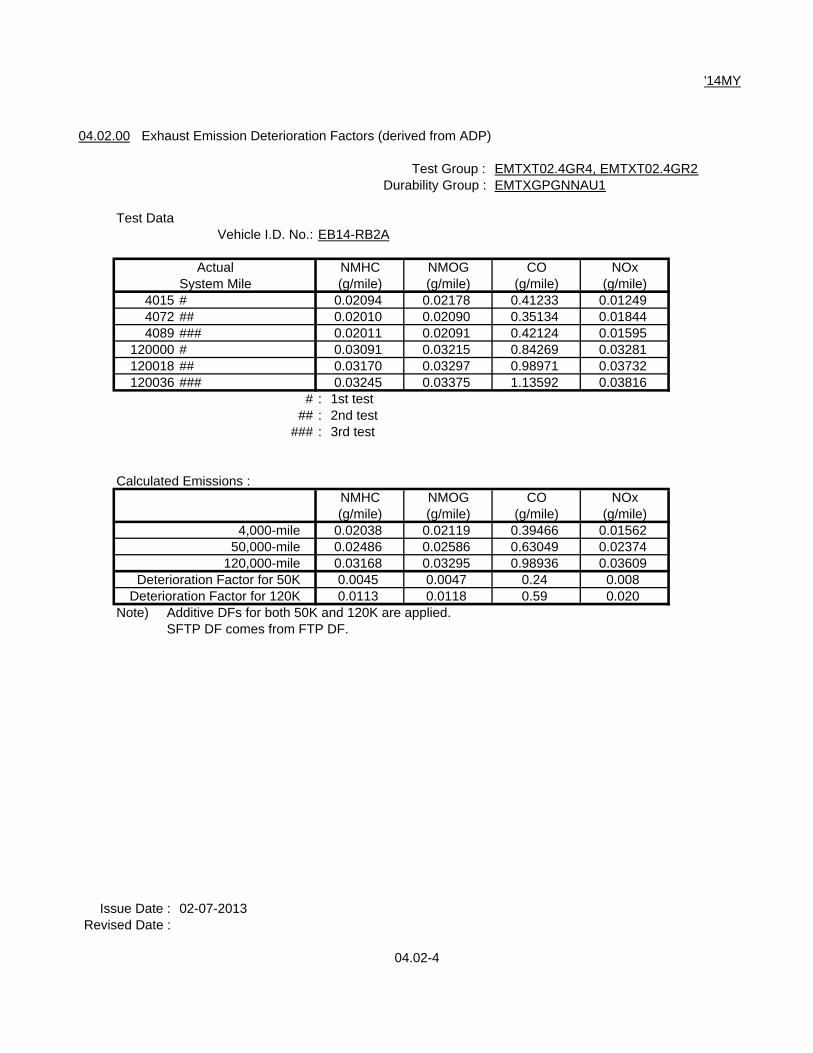
04.04.00 Evap. Emission Deterioration Factors
Evaporative Family : EMTXR0135A1D
Test DataVehicle ID No. : DF07-CA02
Bench (Stabilized Vehicle No. DF07-CA02 )System Test CaseMiles No.1-1 No.1-2 No.2-1 No.2-2 Average
4,000 HC-TEV-3D 0.264 0.257 0.297 0.275 0.273HC-R/L 0.007 0.007 0.006 0.007 0.007HC-TEV-2D 0.277 0.241 0.266 0.274 0.265ORVR 0.016 0.021 0.048 0.079 0.041
150,000 HC-TEV-3D 0.240 0.248 0.223 0.214 0.231HC-R/L 0.009 0.009 0.010 0.010 0.010HC-TEV-2D 0.267 0.269 0.247 0.256 0.260ORVR 0.031 0.017 0.014 0.012 0.019
Deterioration Factor Calculation
3-Day (Bench) 2-Day (Bench)(DBL+HSL) (RL) (DBL+HSL)Interpreted Values : Interpreted Values : Interpreted Values :4,000-mile = 0.273 4,000-mile = 0.007 4,000-mile = 0.265150,000-mile = 0.231 150,000-mile = 0.010 150,000-mile = 0.260D.F. = -0.042 as 0.000 D.F. = 0.003 D.F. = -0.005 as 0.000
Deterioration Factor (additive) : Deterioration Factor (additive) : Deterioration Factor (additive) :DBL+HSL : DF = 0.000 RL : DF = 0.003 DBL+HSL : DF = 0.000
(ORVR)Interpreted Values :4,000-mile = 0.041150,000-mile = 0.019 D.F. = -0.023 as 0.000
Deterioration Factor (additive) :ORVR : DF = 0.000
Issue Date : 02-07-2013Revised Date :
04.04-2

'14MY
04.04.00 Evap. Emission Deterioration Factors
Evaporative Family : EMTXR0135A1C
Test DataVehicle ID No. : DB09-CA06
Bench (Stabilized Vehicle No. DB09-CA06 )System Test CaseMiles No.1-1 No.1-2 No.2-1 No.2-2 Average
4,000 HC-TEV-3D 0.342 0.293 0.274 0.295 0.301HC-R/L 0.008 0.006 0.006 0.006 0.0065HC-TEV-2D 0.325 0.283 0.273 0.279 0.290ORVR 0.006 0.006 0.007 0.008 0.0068
150,000 HC-TEV-3D 0.303 0.267 0.311 0.304 0.296HC-R/L 0.010 0.009 0.008 0.009 0.0090HC-TEV-2D 0.291 0.270 0.294 0.301 0.289ORVR 0.007 0.007 0.008 0.007 0.0073
Deterioration Factor Calculation
3-Day (Bench) 2-Day (Bench)(DBL+HSL) (RL) (DBL+HSL)Interpreted Values : Interpreted Values : Interpreted Values :4,000-mile = 0.301 4,000-mile = 0.0065 4,000-mile = 0.290150,000-mile = 0.296 150,000-mile = 0.009 150,000-mile = 0.289D.F. = -0.005 as 0.000 D.F. = 0.0025 D.F. = -0.001 as 0.000
Deterioration Factor (additive) : Deterioration Factor (additive) : Deterioration Factor (additive) :DBL+HSL : DF = 0.000 RL : DF = 0.003 DBL+HSL : DF = 0.000
(ORVR)Interpreted Values :4,000-mile = 0.0068150,000-mile = 0.0073 D.F. = 0.0005
Deterioration Factor (additive) :ORVR : DF = 0.001
Issue Date : 02-07-2013Revised Date :
04.04-3

'14MY
04.05.00 Determination of DOR Radiator Deterioration Factor
(Reserved this page)
04.05-1

'14MY
05.00.00 TEST GROUP DESCRIPTION
05.01.00 Breakdown of Test Group
E MTX V 01.2 G R B
Character 12 Wild CardG and H : Single StandardB, 2 and 4 : Commonized CA and FED Std. $
Character 11 Emission StandardR : Tier 2 Bin 5 / LEV II LEV or ULEVV : Tier 2 Bin 2 / LEV II SULEVW: Tier 2 Bin 1 / LEV II ZEV
Character 10 FuelG : Gasoline E: Battery ElectricH : Hybrid
Character 6 thru. 9 Displacement00.0 : Battery Electric 01.2 : 1.2L02.0 : 2.0L 02.4 : 2.4L03.0 : 3.0L
Character 5 Family TypeV : LDV T : LDT
Character 2 thru. 4 Manufacturer CodeMTX : MMC
Character 1 Model YearE : 2014
Issue Date : 11-12-2012Revised Date : 02-07-2013 $
05.00-1

'14MY
05.02.00 Engine Code
Engine Code
12 D A - U N N
Character 8 Wild CardNothing : No Variety
Character 7 Charge Air System N : Normal AspirationA : Turbo ChargedB : Low Pressure Turbo Charged
Character 6 EGRN : Without EGRE : With EGR
Character 5 In/Ex Valve ControlC : Conventional S : 2-Cam Profile SystemU : VVT (MIVEC-) V : VVT (MIVEC+)
W : VVT2 (MIVEC2)
Character 4 Fuel CalibrationA-H : Regular Fuel J-N : Premium FuelP-R : Flexible Fuel S : Battery ElectricT-Z : HEV, PHEV
Character 3 Cam - ShaftS : Single Over Head Cam (S4) N: N/AD : Double Over Head Cam (D4)
Character 1 thru 2 Displacement00 : Battery 12 : 1.2L 20 : 2.0L24 : 2.4L 30 : 3.0L
Issue Date : 11-12-2012Revised Date :
05.00-2

'14MY
05.03.00 Test Group Description
See Vol.3 (Vehicle Information)
Issue Date : 11-12-2012Revised Date :
05.00-3

'14MY
08.00.00 EMISSION TESTING WAIVER STATEMENT
08.01.00 Statement of Compliance
Every new motor vehicle manufactured by Mitsubishi for sale in the U. S. A., through Mitsubishi MotorsNorth America, Inc. which is subject to the 2014 model year emission standards, shall be coveredby a certificate of conformity.
Mitsubishi states, as required by 40 Code of Federal Regulations (CFR) sec.86.1810-01(a), (b), (c)& Advisory Circular No.46, that the emission control systems used on these 2014 model yearMitsubishi vehicles :
- will not in its operation or function cause the emission into the ambient air of any noxious or toxicsubstance that would not be emitted in the operation of such vehicle without such system,except as specifically permitted by regulation.
- will not in its operation, function, or malfunction result in any unsafe condition endangering themotor vehicle, its occupants, or persons or property in close proximity to the vehicle.
- were tested in accordance with good engineering practice to ascertain that such test vehicles willmeet the requirements for the useful life of the vehicles.
Mitsubishi states, in accordance with sec.86.1810-01(a), (b), (c) and sec.86.1844-01(g)(2), thatthe vehicle for which certificate is requested comply with the requirements and that the descriptionsof tests performed for confirmation comply with the general standards, and the data derived from such tests, are available to the Administrator upon request.
Mitsubishi states, in accordance with sec.86.1810-01(b), Mitsubishi has ensured that all vehicles havesafe vehicle drivability characteristics within the physically adjustable range of each adjustableparameter.
Mitsubishi states, in accordance with sec.86.1843-01, that the test vehicles for which data aresubmitted to demonstrate compliance with this part and with sec.86.1811-04 are in all material respectsas described in our application for certification, that they have been tested in accordance with theapplicable test procedures utilizing the fuels and equipment described in the application for certification,and that on the basis of such tests, the vehicles conform to the requirements of the regulations. Based on Mitsubishi's good engineering judgement, all the vehicles described in this Application forCertification comply with all applicable intermediate and full useful life standards.
Mitsubishi states that evaporative emission durability conforms to the requirements in sec.86.1843-01.
Issue Date : 11-12-2012Revised Date :
08.00-1

'14MY
Mitsubishi states, in accordance with the provisions of the Advisory Circular No.76-1, that anyelement of design, system, or emission control device installed on or incorporated in Mitsubishi's newmotor vehicles, for the purpose of complying with standards prescribed under section 202 of theClean Air Act, will not, to the best of Mitsubishi's information and belief, cause the emission into theambient air of pollutants in the operation of its motor vehicles which cause or contribute to anunreasonable risk to public health or welfare except as specifically permitted by the standardsprescribed under section 202 of the clean Air Act.
The term pollutant means:a. Nickelb. MMT combustion productsc. Ammoniad. Sulfatese. Hydrogen sulfidef. Hydrogen cyanideg. Ruthenium combustion productsh. Nitrosamines
or any other pollutant which Mitsubishi has identified which can reasonably be expected to be emittedfrom these vehicles.
Mitsubishi states that any element of design, system, or emission control device installed onor incorporated in Mitsubishi's new motor vehicles, for the purpose of complying with standardsprescribed under section 202 of the Clean Air Act, will not, to the best of Mitsubishi's informationand belief, cause unreasonable risk to public safety.
Mitsubishi states, for Tier 2 beginning with the 2004 model year, that all vehicles in this applicationhave a leak-free exhaust system designed for operation over the full useful life of the vehiclein accordance with sec.86.1844-01(d)(16).
Mitsubishi states that no Mitsubishi vehicles are equipped with a defeat device in accordance withCFR sec. 86.1809-01.
Mitsubishi states, in accordance with VPCD-02-19, that the OBD system meets the full intent of boththe Clean Air Act as amended in 1990, section 202(m), and the federal OBD regulations contained insec.86.1806-05, including those provisions pertaining to requests for deficiencies in the limitedinstances where an OBD II system that complies with sec.1968.2 does not comply with all the requirements of sec.1968.1.
Issue Date : 11-12-2012Revised Date :
08.00-2

'14MY
Pursuant to sec. 86.1810-01(i)6 and Part 1, Section D.2. of the California Exhaust EmissionStandards and Test Procedures for 2001 and Subsequent Model Passenger Cars, Light-Duty Trucks,and Medium-Duty Vehicles, Mitsubishi states that during the SC03 driving cycle the air to fuel (A/F)ratio is not richer at any time than the leanest A/F mixture required to obtain maximum torque(lean best torque, or LBT). Mitsubishi also states that during the US06 driving cycle, the A/F ratio ismostly controlled to stoichiometric. Some areas outside of the A/F feedback zone include the area ofA/F ratio for LBT and the area where the A/F mixture is richer than required for LBT by more than 6%,as described in the “Application of Air to Fuel Ratio Control under the SFTP Driving Cycle” submittedseparately. The area where richer A/F mixture is provided is small, and the reason for this enrichmentis to protect the catalytic converters and the oxygen sensors from overheating.
Mitsubishi vehicles meet the requirements for compliance with the NMOG adjustment factor "1.04"for 2006 and subsequent model year according to sec.86.1810-01(p), as allowed by EPA(Letter number: 04VCG-A069, dated on November 22, 2004) and ARB (Letter number: 04VCG-A070,dated on December 17, 2004).
Pursuant to sec.86.1603(b), Mitsubishi has determined that the vehicles within this test group areexempted from the requirements of submitting altitude performance adjustment instructions. All of vehicles within this test group have fuel control system which maintain a stoichiometric air-fuel ratioat all altitude conditions.
Issue Date : 11-12-2012Revised Date :
08.00-3

'14MY
- The Safety Statement for ORVR System -
Mitsubishi states, with respect to vehicles and engines, that any emission control device, system, orelement of design does comply with standards prescribed on sec.202(a)(4) and sec.206(a)(3)(A)-(B)of Clean Air Act (CAA).
Mitsubishi states that ORVR-equipped vehicles meet the applicable requirements in accordance withsec.86.1844-01(g)(2) and that the vehicles for which emission certification is required conform tothe requirement in accordance with sec.86.1810-01(a), (b), (c).
For ORVR-equipped vehicles, Mitsubishi states, in accordance with sec.86.1810-01(a)(2), that anysystem installed on a new motor vehicle to conform to standards shall not, in its operation, function,or malfunction, result in any unsafe condition endangering the motor vehicle, its occupants, or personsor property in close proximity to the vehicle.
Mitsubishi states that ORVR-equipped vehicles meet the applicable FMVSS, including FMVSS 301related to fuel system integrity.
Mitsubishi shows the list for previously certified evaporative/ORVR family from which the currentfamily is being carried over or carried across.
Applicable Applicable Test Group Any Change from Carried Over or Evap/ORVR Family Original System Carried Across fromEMTXR0135A1D EMTXV02.4GRB, EMTXT02.0GR4 No DMTXR0135A1D
EMTXT02.4GR4, EMTXT02.4GR2EMTXT03.0GRB, EMTXT03.0GR4
EMTXR0135A1C EMTXV02.0GRB No DMTXR0135A1C
Mitsubishi states, in accordance with CCD-05-03, that the carried over or carried across ORVR systemslisted above table have been no substantial changes from the previously certified system.
Issue Date : 11-12-2012Revised Date :
08.00-4

'14MY
08.02.00 Emission Testing Waiver Statement
Mitsubishi states, in accordance with sec.86.1829-01(b)(1)(ii)(B) and (b)(2)(ii)(B), the Federal vehiclescomply with both the low and high altitude emission requirements based on Mitsubishi's engineeringevaluation of such high altitude emission testing as Mitsubishi deems appropriate.
Mitsubishi states, in accordance with sec.86.001-21(b)(1)(i)(C), that Mitsubishi's test groups towhich Cold CO emission standard is applied are designed pursuant to the intermediate temperaturecold testing defeat device guidance as described in sec.86.1809-10.
Mitsubishi states, in accordance with sec.86.1829-01(b)(1)(iii)(B), that the design for all vehicles issubstantially similar to existing designs that have particulate levels significantly below the standard,and that these vehicles are expected to demonstrate similar characteristics.
Mitsubishi states, in accordance with sec.86.1829-01(b)(1)(iii)(G), that the design for all vehicles issubstantially similar to existing designs that have N2O emission levels significantly below the standard,and that these vehicles are expected to demonstrate similar characteristics.
Mitsubishi states, in accordance with sec.86.1829-01(b)(4)(i)(B), that the design for all vehicles issubstantially similar to existing designs that have emission levels significantly below the CST standard,and that these vehicles are expected to demonstrate similar characteristics.
Mitsubishi states, in accordance with sec.86.1829-01(b)(1)(iii)(E), that the design for all vehicles issubstantially similar to existing designs that have formaldehyde levels significantly below the standard,and that these vehicles are expected to demonstrate similar characteristics. Mitsubishi vehiclesmeet the requirements for compliance with the formaldehyde standards for 2006 and subsequentmodel years, as allowed by EPA (Letter number: 04VCG-A069, dated on November 22, 2004)and ARB (Letter number: 04VCG-A070, dated on December 17, 2004).
Mitsubishi states, in accordance with VPCD-97-01, that the knock sensor does not activate in anyway during the FTP and the HWFET, and the calibration is designed to operate on 91 RON gasolinewithout the need for spark adjustment. And also, the city and highway fuel economy test resultdifferences between comparing 91 RON operation and 96 RON operation is within 3%, and there areno emissions increases (beyond normal test variability) using 91 RON fuel when tested on the FTP(or SFTP as applicable). Please note that vehicles requiring premium gasoline are excluded from this statement.
Issue Date : 11-12-2012Revised Date :
08.00-5

'14MY
08.03.00 Performance Warranty Testing Exemption or Alternative Procedure at I/M Station for Full-TimeFour-Wheel Drive
Not Applicable
Issue Date : 11-12-2012Revised Date :
08.00-6

'14MY
10.00.00 DESCRIPTION OF ALTERNATIVE-FUELED VEHICLES
Not Applicable
Issue Date : 11-12-2012Revised Date :
10.00-1

'14MY
11.00.00 AECD DESCRIPTION
11.01.00 Auxiliary Emission Control Features
See Vol. 2-1 (Section 11.01.00)
Issue Date : 11-12-2012Revised Date :
11.00-1

'14MY
12.00.00 DESCRIPTION OF VEHICLES COVERED BY CERTIFICATE AND TEST PARAMETERS
12.01.00 Vehicle Parameters
See Vol.3 (Section 12.01.00)
12.02.00 Emission Control System Description
See Vol.2-1 (Section 09.04.02)
Issue Date : 11-12-2012Revised Date :
12.00-1

'14MY
12.03.00 Test Parameters
12.03.01 Engine Starting Procedure
(1) Vehicles not equipped with Engine Switch (Automatic Transmission)1. Close door.2. Insert the ignition key if not equipped F.A.S.T. key, and fasten seat belt.3. Place the selector lever of Automatic Transmission in “P”(Park) or “N”(Neutral) position. *14. Cold & Warm Engine:
No throttle depression, turn the ignition key to start position and release when engine starts.
(2) Vehicles not equipped with Engine Switch (Manual Transmission)1. Close door.2. Insert the ignition key if not equipped F.A.S.T. key, and fasten seat belt.3. Place the gearshift lever of the Manual Transmission in "Neutral".4. Cold & Warm Engine:
1) Depress and hold clutch pedal. *22) No throttle depression, turn the ignition key to start position and release when engine starts.
(3) Vehicles equipped with Engine Switch (Automatic Transmission)1. Close door and fasten seat belt.2. Place the selector lever of Automatic Transmission in “P”(Park) or “N”(Neutral) position.*33. Press Engine Switch once in any indicator light condition (Off or Orange or Green)
(4) Vehicles equipped with Engine Switch (Manual Transmission)1. Close door and fasten seat belt.2. Depress and hold clutch pedal. *23. Press Engine Switch once in any indicator light condition (Off or Orange or Green)
Notes) *1 : Vehicles equipped with Automatic Transmission have shift-lock device that holdsthe selector lever in "P" (Park) position.To move the selector lever from “P”(Park) position to another position, follow the stepsbelow.
(1) Depress and hold brake pedal.(2) Move the selector lever to the desired position.
When removing key, first set the selector lever to "P"(Park) position, and then turnkey to "LOCK" position and remove it.
*2 : All light duty vehicles having Manual Transmission are equipped with clutch switch.*3 : Vehicles equipped with Automatic Transmission have shift-lock device that holds
the selector lever in “P”(Park) position. To move the selector lever from “P”(Park) position to another position, follow the stepsbelow.
(1) Without pressing brake pedal, press Engine Switch twice.Do not press brake pedal while pressing Engine Switch.
(2) Depress and hold brake pedal while moving the selector lever to the desiredposition.
Issue Date : 11-12-2012Revised Date :
12.03-1

'14MY
12.03.02 Shift Schedule
1. EPA Shift Schedule No.
ModeTest Group*1 T/M City Highway US06 SC03
EMTXV01.2GRB M5 490-#19 490-#20 490-#22 490-#23EMTXV02.4GRBEMTXV02.0GRB M5 FT5 HW5 490-#27 490-#26
EMTXT02.0GR4 M5 FT5 HW5 490-#22 490-#23 $
*1 : See Vol.1, Page 00.00-1
Note) Semi-automatic transmission Manual Shift Mode is not shown since vehicles equippedwith these transmissions were tested in "D-range" only.Please see Section 12.03.03 for more details.
2. Shift Speed
(1) Upshift Schedules (For City, Hwy)Test Alti- Except for
Group T/M tude Gear City 2nd *1 and City 2nd *1 and20th Hill (mph) 20th Hill (mph)
EMTXV01.2GRB M5 L 1st to 2nd 15 / 15 *2 15EMTXV02.4GRB 2nd to 3rd 28 / 19 *2 28
3rd to 4th 36 / 33 *2 404th to 5th 45 / 45 *2 45
H 1st to 2nd 15 152nd to 3rd 25 303rd to 4th 40 454th to 5th 45 50
Test Alti- Except for City CityGroup T/M tude Gear City 1st and 1st Hill 2nd Hill *1
2nd Hill (mph) (mph) (mph)EMTXV02.0GRB M5 L 1st to 2nd 15 Same as left Same as leftEMTXT02.0GR4 & 2nd to 3rd 25 $
H 3rd to 4th 404th to 5th 45
*1 : From 187sec through 220sec in city mode*2 : Accel / Cruise
Issue Date : 11-12-2012Revised Date : 02-07-2013, 04-04-2013 $
12.03-2

'14MY
(2) Downshift Schedules (For City, Hwy)Test
Group T/M Mode Time (sec.) GearEMTXV01.2GRB M5 City 186 3rd to 2ndEMTXV02.4GRB 840 4th to 2nd
Hwy 296 5th to 3rd
EMTXV02.0GRB M5 City 187 3rd to 2ndEMTXT02.0GR4 840 3th to 2nd $
Hwy N/A N/A
(3) Upshift Schedules (For SFTP)Test US06 SC03
Group T/M Gear (mph) (mph)EMTXV01.2GRB M5 1st to 2nd 22 15EMTXV02.4GRB 2nd to 3rd 39 25EMTXT02.0GR4 3rd to 4th 56 40 $
4th to 5th 66 45EMTXV02.0GRB M5 1st to 2nd 20 18
2nd to 3rd 35 303rd to 4th 50 404th to 5th 60 50
Note) Semi-automatic transmission Manual Shift Mode in this section (2. Shift Speed)is not shown since vehicles equipped with these transmissions were tested in "D-range" only.Please see Section 12.03.03 for more details.
Issue Date : 11-12-2012Revised Date : 02-07-2013, 04-04-2013 $
12.03-3

'14MY
(4) Downshift Schedules (For SFTP)Test
Group T/M Mode Time (sec.) GearEMTXV01.2GRB M5 US06 N/A N/AEMTXV02.4GRB EMTXT02.0GR4 SC03 432 3rd to 2nd $
EMTXV02.0GRB M5 US06 N/A N/A
SC03 434 3rd to 2nd
Note) Semi-automatic transmission Manual Shift Mode in this section (2. Shift Speed)is not shown since vehicles equipped with these transmissions were tested in "D-range" only.Please see Section 12.03.03 for more details.
Issue Date : 11-12-2012Revised Date : 02-07-2013, 04-04-2013 $
12.03-4

'14MY
12.03.03 Semi-Automatic Transmission Survey
In accordance with Dear Manufacturer Letter CISD-09-19, Mitsubishi performed the certificationtests for the vehicles with the semi-automatic transmission have been tested by D-range only.
The following table indicates which models have satisfied the requirement and are exempt fromtesting in the selectable shift mode.
Test Group Engine ETW Power ETW/Power Default mode Shift Previous Remarks(hp) (>15.0) at key-off? Survey? Survey Report
EMTXV02.4GRB 2.4L 3500 168 Yes Yes N/A 07CCG-A098 Test by(20.8) Nov.22, 2007 Default
for 2008MY modeEMTXV02.0GRB 2.0L 4000 291 No Yes Complete C/O Report Test by
T/C (13.7) 10CCG-A006 Default"Feb.24,2010" modefor 2008MY &
2009MY EMTXT02.0GR4 2.0L 3625 148 Yes Yes N/A N/A Test by $
(24.5) Defaultmode
EMTXT02.4GR4 2.4L 3750 166 Yes Yes N/A N/A Test by(22.6) Default
modeEMTXT02.4GR2 2.4L 3875 166 Yes Yes N/A N/A Test by
(23.3) Defaultmode
EMTXT03.0GRB 3.0L 4000 227 Yes Yes N/A N/A Test by(17.6) Default
modeEMTXT03.0GR4 3.0L 4000 224 Yes Yes N/A N/A Test by
(17.9) Defaultmode
Issue Date : 11-12-2012Revised Date : 02-07-2013, 04-04-2013 $
12.03-5

'14MY
12.03.04 Dyno Loading Information
Vehicle Test Trans. Tire Size ETW Target Coefficients C/DModel Group type Time
A B CMIRAGE EMTXV01.2GRB CVT P165/65R14 2375 15.205 0.19055 0.016010 17.04
(1.2L) (2WD)M5 P165/65R14 2375 13.058 0.20308 0.015708 17.77
(2WD)Lancer EMTXV02.4GRB S-CVT P215/45R18 3500 43.357 -0.17555 0.022994 17.63 $
Sportback (2WD)(2.4L)
M5 P215/45R18 3500 24.005 0.34357 0.017847 18.94(2WD)
Lancer S-CVT P205/60R16 3375 41.959 -0.31718 0.024077 18.14 $Sportback (2WD)
(2.0L) M5 P205/60R16 3250 20.032 0.32624 0.017997 18.56(2WD)
Lancer S-CVT P205/60R16 3500 43.357 -0.17555 0.022994 17.63 $(2.4L) (AWD) *1 *1 *1 *1
S-CVT P215/45R18 3375 48.755 -0.35942 0.023594 17.43(2WD)
M5 P215/45R18 3375 22.608 0.40551 0.016034 18.89(2WD)
Lancer S-CVT P205/60R16 3250 33.897 -0.07177 0.020155 18.68 $(2.0L) (2WD)
M5 P205/60R16 3250 19.004 0.33186 0.015420 20.35(2WD) 3125
Lancer EMTXV02.0GRB 6SST 245/40R18 4000 43.512 0.50916 0.019935 15.61 $ Evolution (AWD) *1 *1 *1 *1
M5 245/40R18 3875 46.337 0.63264 0.019137 14.28(AWD) *1 *1 *1 *1
Lancer 6SST 215/45R18 or 3875 39.495 0.53252 0.017156 16.48 $(AWD) P215/45R18 *1 *1 *1 *1
Lancer 6SST 215/45R18 or 3875 39.495 0.53252 0.017156 16.48 $Sportback (AWD) P215/45R18 *1 *1 *1 *1
*1 : This values are assigned for 2 wheel drive chassis dynamometer testing.
Issue Date : 11-12-2012Revised Date : 02-07-2013 $
12.03-6

'14MY
Vehicle Test Trans. Tire Size ETW Target Coefficients C/DModel Group type Time
A B COutlander EMTXT02.0GR4 S-CVT P225/55R18 3625 30.074 0.24380 0.022034 17.29 $
Sport (RVR) (4WD) *1 *1 *1 *1(2.0L) P215/70R16 30.622 0.16079 0.022754 17.61
*1 *1 *1 *1S-CVT P225/55R18 3500 31.309 0.06388 0.023984 17.20(2WD)
P215/70R16 31.557 0.07348 0.022872 17.58
M5 P225/55R18 3375 20.084 0.43542 0.022027 16.18(2WD)
P215/70R16 17.060 0.29712 0.020972 18.60
Outlander EMTXT02.4GR4 S-CVT P225/55R18 3625 36.962 -0.13456 0.026053 17.65(2.4L) (2WD)
P215/70R16 34.988 -0.14988 0.024654 18.88
S-CVT P215/70R16 3750 40.410 -0.07580 0.025840 17.19(4WD) *1 *1 *1 *1
EMTXT02.4GR2 S-CVT P225/55R18 3875 40.410 -0.07580 0.025840 17.77(4WD) *1 *1 *1 *1
Outlander EMTXT03.0GRB S6 P225/55R18 4000 23.555 0.57248 0.019957 18.20(3.0L) (4WD) *1 *1 *1 *1
P215/70R16 4000 22.008 0.51480 0.019122 19.44 *1 *1 *1 *1
EMTXT03.0GR4 S6 P225/55R18 4000 23.555 0.57248 0.019957 18.20(4WD) *1 *1 *1 *1
*1 : This values are assigned for 2 wheel drive chassis dynamometer testing.
Issue Date : 02-07-2013Revised Date : 04-04-2013 $
12.03-7

'14MY
12.04.00 Evap. Test Parameters
See Vol.3 (Section 12.04.00)
Issue Date : 11-12-2012Revised Date :
12.04-1

'14MY
13.00.00 PROJECTED SALES
13.01.00 Phase-in Implementation Schedule
See Vol.2-1 (Section 13.01.00)
13.02.00 Test Group Projected National Vehicle Sales
See Vol.2-1 (Section 13.02.00)
13.03.00 Final US Sales
See Vol.2-1 (Section 13.03.00)
Issue Date : 11-12-2012Revised Date :
13.00-1

'14MY
15.00.00 OTHER INFORMATION
15.01.00 Fee Filing Form
See Vol.3 (Section 15.01.00)
Issue Date : 11-12-2012Revised Date :
15.00-1

'14MY
15.02.00 ORVR Approval
See compliance statement in Volume 1, Section 08.01.00.
Issue Date : 11-12-2012Revised Date :
15.00-2

'14MY
15.03.00 ORVR Notification
See compliance statement in Volume 1, Section 08.01.00.Applicable Vehicle Model : EMTXV01.2GRB
Issue Date : 11-12-2012Revised Date :
15.00-3

'14MY
15.03.00 ORVR Notification
See compliance statement in Volume 1, Section 08.01.00.Applicable Vehicle Model : EMTXV02.4GRB, EMTXV02.0GRB, EMTXT02.0GR4, EMTXT02.4GR4,
EMTXT02.4GR2, EMTXT03.0GRB, EMTXT03.0GR4
Issue Date : 11-12-2012Revised Date :
15.00-4

'14MY
16.00.00 Notice of CONFIDENTIAL INFORMATION
16.01.00 Notice of Confidential Business Information
All pages under this cover marked in any form with the word CONFIDENTIAL constitute confidentialbusiness information and trade secrets of the Mitsubishi Motors Corporation.
DURATION OF CONFIDENTIALITYFOI Application Until issuance of Certification of ConformityCBI Application Permanent
ALL PORTIONS OF THIS DOCUMENT, AND ALL INFORMATION CONTAINEDHEREIN, ARE DEEMED CONFIDENTIAL INFORMATION
OF THE MITSUBISHI MOTORS CORPORATION.
Use, publication or release of this confidential information by unauthorized persons is not permittedwithout the express written consent of Mitsubishi.
Please address any inquiries concerning this information to:
Hayami NakagawaDirectorMitsubishi Motors R & D of America, Inc. (MRDA)Ann Arbor Laboratory $
3735, Varsity Drive, Ann Arbor, Michigan 48108 $U.S.A.
Telephone Number : 734-971-0900 $FAX Number : 734-971-0901 $
Issue Date : 11-12-2012Revised Date : 12-19-2013
16.00-1

'14MY
17.00.00 CALIFORNIA ARB INFORMATION
2014 Model Year Product Line Feature
Test Model T/M Exhaust Emission Special NoteGroup Control System Feature
EMTXV01.2GRB MIRAGE CVT A/F Sensor, WUTWC SFI, $M5 HO2S, TWC OBD-II,
MIVEC EMTXV02.4GRB Lancer/ S-CVT EGR, A/F Sensor, TWC, SFI, *1 $
Lancer Sportback M5 HO2S, TWC OBD-II, $MIVEC
EMTXV02.0GRB Lancer Evolution/ 6SST HO2S, TWC, HO2S, TWC, SFI, $Lancer/ M5 TC, CAC OBD-II,
Lancer Sportback MIVEC EMTXT02.0GR4 Outlander Sport S-CVT EGR, A/F Sensor, WUTWC, SFI, *1 $
(RVR) M5 HO2S, TWC OBD-II,MIVEC
EMTXT02.4GR4 Outlander S-CVT A/F Sensor, WUTWC, SFI, $HO2S, TWC OBD-II,
MIVECEMTXT02.4GR2 Outlander S-CVT A/F Sensor, WUTWC, SFI, $
HO2S, TWC OBD-II,MIVEC
EMTXT03.0GRB Outlander S6 EGR, 2A/F Sensor, 2WUTWC, SFI, *1 $2HO2S, TWC OBD-II, $
MIVECEMTXT03.0GR4 Outlander S6 EGR, 2A/F Sensor, 2WUTWC, SFI, *1 $
2HO2S, TWC OBD-II, $MIVEC
Notes)$
*1 : Electronic controlled EGR system is installed. $$
Issue Date : 11-12-2012Revised Date : 02-07-2013, 04-04-2013 $
17.00-1

'14MY
17.01.00 Test Procedure
17.01.01 High Altitude Emission Testing
In order to comply with "California Exhaust Emission Standards and Test Procedures for 2001 andSubsequent Model Year Passenger Cars, Light-Duty Trucks, and Medium-Duty Vehicles", Part lSection G(3.1.1), last amended August 4, 2005, relating to the California High Altitude TestRequirement, Mitsubishi vehicles are equipped with a barometric pressure sensor (or equivalent)which is utilized as a high altitude compensator.
17.01.02 Evap. Emission Bench Test Procedure
See evaporative system durability procedure in Volume 1, Section 04.03.00.
Issue Date : 11-12-2012Revised Date :
17.01-1

'14MY
17.01.03 Alternative Test Procedure
Applicable Vehicle Model : Except for Lancer Evolution
Issue Date : 11-12-2012Revised Date :
17.01-2

'14MY
17.01.03 Alternative Test Procedure
Applicable Vehicle Model : Lancer Evolution
Issue Date : 11-12-2012Revised Date :
17.01-3

'14MY
17.02.00 Warranty Statement and Maintenance Schedule
17.02.01 Emission System Warranty Statement
See compliance statement in Volume 1, Section 17.04.01.
17.02.02 Maintenance Schedule
All maintenance schedules for specific mileage intervals will be included in the owner's manual, to besupplied to the ultimate Mitsubishi vehicle purchaser.
Issue Date : 11-12-2012Revised Date :
17.02-1

'14MY
17.03.00 Fill Pipe Access Zone Statement and Specifications
See compliance statement in Volume 1, Section 17.04.01.
Issue Date : 11-12-2012Revised Date :
17.03-1

'14MY
AIR RESOURCES BOARD APPLICATION FORMATFOR COMPLIANCE WITH THE FILL PIPE REQUIREMENTS
Manufacturer Mitsubishi Motors CorporationTest Group EMTXV01.2GRBVehicle Model(s) MIRAGE
The nomenclature and symbols used below are the same as those defined in "Specifications for Fill Pipesand Openings of Motor Vehicle Fuel Tanks", last amended March 22, 2012.
ARB ManufacturerGeneral Specification Specification Specification*1
(1) Angle "a" in degrees -10 deg. <= a <= 20 deg. -2.35 deg. $(2) Spill prevention in degrees 30 deg. (MIN) 40.5 deg.
(angle between centerline of test spout in its resting position and the horizontal plane)
(3) Test nozzle penetration of restrictor 2.25 CM (MIN) 2.62 $(4) Angle "b" in degrees none 0.32 deg. $
Fill Pipe Specification
(1) Fill pipe face surface in TIR 0.025 CM (MAX) 0.020(2) Fill pipe face outside diameter 5.75 CM (MAX) 5.33(3) Internal locking lip in degrees of the 100 deg. (MIN) 360 deg.
inside circumference(a) degrees extending each side of reference 35 deg. (MIN) LS *2 270 deg.
plane each side RS *2 90 deg.(4) Height of lip measured from fill pipe inside 0.25 CM (MIN) 0.29
wall; or height of lip measured from fill pipeoutside wall for outside diameters between 0.85 CM (MIN) N/A5.20 and 5.75 CM
(5) Depth of lip(D) in centimeters 0.4 <= D <= 1.3 1.03 thru 1.13
OffsetOffset A none 0.27Offset B none 0.01 $
Notes) *1 : dimension should include adverse tolerance condition*2 : LS = Left side of reference plane
RS = Right side of reference plane
Issue Date : 11-12-2012Revised Date : 05-28-2013 $
17.03-2

'14MY
AIR RESOURCES BOARD APPLICATION FORMATFOR COMPLIANCE WITH THE FILL PIPE REQUIREMENTS
Manufacturer Mitsubishi Motors CorporationTest Group EMTXV02.4GRBVehicle Model(s) Lancer, Lancer Sportback
The nomenclature and symbols used below are the same as those defined in "Specifications for Fill Pipesand Openings of Motor Vehicle Fuel Tanks", last amended March 22, 2012.
ARB ManufacturerGeneral Specification Specification Specification*1
(1) Angle "a" in degrees -10 deg. <= a <= 20 deg. -2 deg.(2) Spill prevention in degrees 30 deg. (MIN) 33.5 deg.
(angle between centerline of test spout in its resting position and the horizontal plane)
(3) Test nozzle penetration of restrictor 2.25 CM (MIN) 4.40(4) Angle "b" in degrees none 1.7 deg.
Fill Pipe Specification
(1) Fill pipe face surface in TIR 0.025 CM (MAX) 0.020(2) Fill pipe face outside diameter 5.75 CM (MAX) 5.73(3) Internal locking lip in degrees of the 100 deg. (MIN) 360 deg.
inside circumference(a) degrees extending each side of reference 35 deg. (MIN) LS *2 281.8 deg.
plane each side RS *2 78.2 deg.(4) Height of lip measured from fill pipe inside 0.25 CM (MIN) 0.29
wall; or height of lip measured from fill pipeoutside wall for outside diameters between 0.85 CM (MIN) N/A5.20 and 5.75 CM
(5) Depth of lip(D) in centimeters 0.4 <= D <= 1.3 1.05 thru 1.15
OffsetOffset A none 0.26Offset B none 0.07
Notes) *1 : dimension should include adverse tolerance condition*2 : LS = Left side of reference plane
RS = Right side of reference plane
Issue Date : 02-07-2013Revised Date :
17.03-3

'14MY
AIR RESOURCES BOARD APPLICATION FORMATFOR COMPLIANCE WITH THE FILL PIPE REQUIREMENTS
Manufacturer Mitsubishi Motors CorporationTest Group EMTXV02.0GRBVehicle Model(s) Lancer Evolution, Lancer, Lancer Sportback
The nomenclature and symbols used below are the same as those defined in "Specifications for Fill Pipesand Openings of Motor Vehicle Fuel Tanks", last amended March 22, 2012.
ARB ManufacturerGeneral Specification Specification Specification*1
(1) Angle "a" in degrees -10 deg. <= a <= 20 deg. -2 deg.(2) Spill prevention in degrees 30 deg. (MIN) 33.5 deg.
(angle between centerline of test spout in its resting position and the horizontal plane)
(3) Test nozzle penetration of restrictor 2.25 CM (MIN) 4.40(4) Angle "b" in degrees none 1.7 deg.
Fill Pipe Specification
(1) Fill pipe face surface in TIR 0.025 CM (MAX) 0.020(2) Fill pipe face outside diameter 5.75 CM (MAX) 5.73(3) Internal locking lip in degrees of the 100 deg. (MIN) 360 deg.
inside circumference(a) degrees extending each side of reference 35 deg. (MIN) LS *2 281.8 deg.
plane each side RS *2 78.2 deg.(4) Height of lip measured from fill pipe inside 0.25 CM (MIN) 0.29
wall; or height of lip measured from fill pipeoutside wall for outside diameters between 0.85 CM (MIN) N/A5.20 and 5.75 CM
(5) Depth of lip(D) in centimeters 0.4 <= D <= 1.3 1.05 thru 1.15
OffsetOffset A none 0.26Offset B none 0.07
Notes) *1 : dimension should include adverse tolerance condition*2 : LS = Left side of reference plane
RS = Right side of reference plane
Issue Date : 02-07-2013Revised Date :
17.03-4

'14MY
AIR RESOURCES BOARD APPLICATION FORMATFOR COMPLIANCE WITH THE FILL PIPE REQUIREMENTS
Manufacturer Mitsubishi Motors CorporationTest Group EMTXT02.4GR4, EMTXT02.4GR2, EMTXT03.0GRB, EMTXT03.0GR4Vehicle Model(s) Outlander
The nomenclature and symbols used below are the same as those defined in "Specifications for Fill Pipesand Openings of Motor Vehicle Fuel Tanks", last amended March 22, 2012.
ARB ManufacturerGeneral Specification Specification Specification*1
(1) Angle "a" in degrees -10 deg. <= a <= 20 deg. -1.9 deg.(2) Spill prevention in degrees 30 deg. (MIN) 33.5 deg.
(angle between centerline of test spout in its resting position and the horizontal plane)
(3) Test nozzle penetration of restrictor 2.25 CM (MIN) 4.55(4) Angle "b" in degrees none 2.5 deg.
Fill Pipe Specification
(1) Fill pipe face surface in TIR 0.025 CM (MAX) 0.020(2) Fill pipe face outside diameter 5.75 CM (MAX) 5.33(3) Internal locking lip in degrees of the 100 deg. (MIN) 134 deg.
inside circumference(a) degrees extending each side of reference 35 deg. (MIN) LS *2 67 deg.
plane each side RS *2 67 deg.(4) Height of lip measured from fill pipe inside 0.25 CM (MIN) 0.28
wall; or height of lip measured from fill pipeoutside wall for outside diameters between 0.85 CM (MIN) N/A5.20 and 5.75 CM
(5) Depth of lip(D) in centimeters 0.4 <= D <= 1.3 1.17 thru 1.27
OffsetOffset A none 0.26Offset B none 0.10
Notes) *1 : dimension should include adverse tolerance condition*2 : LS = Left side of reference plane
RS = Right side of reference plane
Issue Date : 02-07-2013Revised Date :
17.03-5

'14MY
AIR RESOURCES BOARD APPLICATION FORMATFOR COMPLIANCE WITH THE FILL PIPE REQUIREMENTS
Manufacturer Mitsubishi Motors CorporationTest Group EMTXT02.0GR4Vehicle Model(s) Outlander Sport (RVR)
The nomenclature and symbols used below are the same as those defined in "Specifications for Fill Pipesand Openings of Motor Vehicle Fuel Tanks", last amended March 22, 2012.
ARB ManufacturerGeneral Specification Specification Specification*1
(1) Angle "a" in degrees -10 deg. <= a <= 20 deg. -1.9 deg.(2) Spill prevention in degrees 30 deg. (MIN) 33.5 deg.
(angle between centerline of test spout in its resting position and the horizontal plane)
(3) Test nozzle penetration of restrictor 2.25 CM (MIN) 4.55(4) Angle "b" in degrees none 2.5 deg.
Fill Pipe Specification
(1) Fill pipe face surface in TIR 0.025 CM (MAX) 0.020(2) Fill pipe face outside diameter 5.75 CM (MAX) 5.73(3) Internal locking lip in degrees of the 100 deg. (MIN) 134 deg.
inside circumference(a) degrees extending each side of reference 35 deg. (MIN) LS *2 67 deg.
plane each side RS *2 67 deg.(4) Height of lip measured from fill pipe inside 0.25 CM (MIN) 0.28
wall; or height of lip measured from fill pipeoutside wall for outside diameters between 0.85 CM (MIN) N/A5.20 and 5.75 CM
(5) Depth of lip(D) in centimeters 0.4 <= D <= 1.3 1.17 thru 1.27
OffsetOffset A none 0.26Offset B none 0.10
Notes) *1 : dimension should include adverse tolerance condition*2 : LS = Left side of reference plane
RS = Right side of reference plane
Issue Date : 04-04-2013Revised Date :
17.03-6

'14MY
17.04.00 Request for Certificate
17.04.01 Statement of Compliance
Mitsubishi states :that 2014model year production vehicles will be in all material respects the same as those forwhich certification is granted.
that vehicle emission control information labels and vacuum hose routing diagrams for 2014model year vehicles comply with the requirements of 40 Code of Federal Regulations (CFR) sec. 86.1807-01 and -07 and California Exhaust Emission Standards and Test Procedures for 2001 and Subsequent Model Vehicles (last amended August 4, 2005).
that all 2014MY MMC test groups will affix the Federal Fuel Economy and Environmental Label that complies with the requirements of California Environmental Performance Label Specifications for 2009 and Subsequent Model Vehicles (as amended March 22, 2012).
that those vehicles for which certification is requested have driveability and performancecharacteristics which satisfy Mitsubishi's customary driveability and performance requirements forvehicles sold in the United States.
that maintenance and procedures consistent with the restrictions imposed under sec.86.1808-01and -07 are necessary to assure that the vehicles covered by a Certificate of Conformity and/oran Executive Order will, in normal use, conform to the regulations.
that all Mitsubishi vehicles will meet the I/M standards when pre-conditioned and tested at ambienttemperatures from 35 to 68 degrees Fahrenheit because, regardless of ambient temperature, theengine coolant temperature is used to control the air-fuel feed back control system, as a functionof temperature.
that the emission control system service information availability requirements of California Healthand Safety Code Section 49036.2 are being met through a program managed by MitsubishiMotors North America, Inc.
that the OBD system meets the full intent of both the Clean Air Act as amended in 1990, section202(m), and the federal OBD regulations contained in sec.86.1806-05 including those provisionspertaining to requests for deficiencies.
that the OBD system meets the California Air Resources Board OBD requirements as containedin sec.1968, et seq., Title 13 CCR, as applicable.
that all PZEVs meet the applicable on-board diagnostic requirements in section 1968.2 of Title 13CCR, as applicable, for 150,000 miles in accordance with Section C.3. of the California Exhaust Emission Standards and Test Procedures for 2009 and Subsequent Model Zero-Emission Vehiclesand Hybrid Electric Vehicles, in the Passenger Car, Light-Duty Truck and Medium-Duty Vehicle Classes.
Issue Date : 11-12-2012Revised Date :
17.04-1

'14MY
that all LEV II vehicles meet the requirements for compliance with the Particulate Matter (PM)standards for 2004 and subsequent model year LEV II vehicles, as allowed by ARB approval(email authorization of January 14, 2004).
that all LEV II vehicles meet the requirements for the formaldehyde standards for 2007 andsubsequent model year LEV II vehicles in accordance with 40 CFR sec.86.1829-01(b)(1)(iii)(E),as allowed by EPA (Letter number: 04VCG-A069, dated on November 22, 2004)and ARB (Letter number: 04VCG-A070, dated on December 17, 2004).
that all LEV II vehicles meet the requirement of Standards and Test Procedures for 2001 and Subsequent Model Vehicles, Part I, Sec.E.1.4 (50 deg.F Requirement).
that all LEV II vehicles meet the requirements for California Inspection & Maintenance (I/M)emissions standards (Idle/2500 RPM and ASM), as allowed under Standards and Test Procedures Section G.3.1.4., last amended September 5, 2003.
that the Emission Control System Warranty meets the requirements of Title 13 CCR, sec.2035 et seq., and that a copy of the warranty is supplied to ARB with or before the Part II application, and supplied to purchasers of Mitsubishi vehicle.
that all PZEVs extend the performance and defect warranty period set forth in sections 2037(b)(2)and 2038(b)(2) to 15 years or 150,000 miles, whichever occurs first in accordance with Section C.3.of the California Exhaust Emission Standards and Test Procedures for 2009 and Subsequent ModelZero-Emission Vehicles and Hybrid Electric Vehicles, in the Passenger Car, Light-Duty Truck andMedium-Duty Vehicle Classes.
that is certified to the 150,000 mile standards in section 1961(a) extends the warranty on high costparts to 8 years or 100,000 miles, whichever occurs first, and agrees to extend the limit on highmileage in-use testing.
that the fill pipe access zones for the models covered by this Application for Certification are incompliance with the requirements specified by the Air Resources Board's "Specifications for FillPipes and Openings of Motor Vehicle Fuel Tanks " adopted March 19, 1976 and amendedJanuary 22, 1990 (Title 13, CCR, sec.2235 [adopted September 17, 1991] ) and are not obstructedin any manner by bumpers, body parts, body trim or accessories that are either factory ordealer installed.
Issue Date : 11-12-2012Revised Date :
17.04-2

'14MY
that the fill pipes installed on all production models listed herein are in compliance with all of therequirements of the Air Resources Board's "Specifications for Fill Pipes and Openings of MotorVehicle Fuel Tanks " amended January 22, 1990, (Title 13, CCR, sec.2235).
that all vehicles complies with High Altitude testing requirements of 40CFR sec.86.1829-01, asmodified by the "California Exhaust Emission Standards and Test Procedures for 2001 andSubsequent Model Passenger Cars, Light-Duty Trucks and Medium-Duty Vehicles", Part ISec. G.3.1.1, last amended August 4, 2005.
Issue Date : 11-12-2012Revised Date :
17.04-3

'14MY
17.04.02 Supplemental Data Sheet
See Vol.3 (Section 17.04.02)
17.04.03 Certification Review Sheet
See Vol.3 (Section 17.04.03)
Issue Date : 11-12-2012Revised Date :
17.04-4

'14MY
17.06.00 I/M Testing
See compliance statement in Volume 1, Section 17.04.01.
17.07.00 ASM Testing
See compliance statement in Volume 1, Section 17.04.01.
17.09.00 California Projected Sales
See Vol.2-1 (Section 17.09.00)
17.10.00 California Phase-in Schedule
See Vol.2-1 (Section 17.10.00)
Issue Date : 11-12-2012Revised Date :
17.06-1

'14MY
18.00.00 REFERENCES
18.01.00 Certification Change
See Vol.2-1(Section 18.00.00)
Issue Date : 11-12-2012Revised Date :
18.00-1

Application for Certification - Part 2
2014 Model Year
MITSUBISHI MOTORS CORPORATION
For Questions, Contact :David Patterson, MRDA-CYP (TEL) 714 372-6000, (FAX) 714 372-6243

2014 MY MMC Application for Certification
File Name : Part 2
Section No. Content00.00.00 Preface01.00.00 Part Numbers02.00.00 Calibration Information03.00.00 Detailed Description of Vehicles Covered by Certificate and Test Parameters04.00.00 Final US Sales05.00.00 Service Manuals, Service Bulletins06.00.00 Engineering Evaluation Demonstrating Continuity in Emissions17.00.00 California ARB Information

'14MY
PREFACE
A. Test Group
Model Name Test Group Emission Sales AreaStandard
MIRAGE EMTXV01.2GRB Tier 2 Bin 5 50-StatesLEV II LEV
Lancer EMTXV02.4GRB Tier 2 Bin 5 50-StatesLEV II LEV
Lancer Sportback
Lancer Evolution EMTXV02.0GRB Tier 2 Bin 5 50-StatesLEV II LEV
Lancer
Lancer Sportback
Outlander Sport EMTXT02.0GR4 Tier 2 Bin 5 50-States(RVR) LEV II ULEV
Outlander EMTXT02.4GR4 Tier 2 Bin 5 50-StatesLEV II ULEV
Outlander EMTXT02.4GR2 Tier 2 Bin 5 50-StatesLEV II ULEV
Outlander EMTXT03.0GRB Tier2 Bin 5 CanadaLEV II LEV
Outlander EMTXT03.0GR4 Tier 2 Bin 5 50-StatesLEV II ULEV
Issue Date : 12-19-2013Revised Date :
2-00.00-1

'14MY
B. Emission Control System Acronyms
AIS : Auto Idle Speed (motor)A/F Sensor : Air Fuel Ration SensorAFS : Air Flow SensorAPS : Accelerator Pedal Position SensorBPS : Barometric Pressure SensorCAC : Charge Air CoolerCAN : Evap. Canister or Controller Area NetworkCAS : Crank Angle SensorC.C : Catalytic Converter CPS : Cam Position SensorCVT : Continuously Variable TransmissionDOHC : Double Over Head CamshaftDOR : Direct Ozone ReductionECM : Engine Control ModuleECTS : Engine Coolant Temperature SensorEET : Electric EGR TransducerEGR : Exhaust Gas RecirculationESC : Electronic Spark Control IgniterESS : Engine Speed SensorETV : Electronic Throttle ValveFLICS : Flow Limited Idle Speed Control SystemFLS : Fuel Level SensorFTPS : Fuel Tank Pressure SensorFTS : Fuel Temperature SensorHAFS : Heated Air Fuel Ratio SensorHC Adsorber TWC : Hydrocarbon Adsorber Three Way Catalytic ConverterHO2S : Heated Oxygen SensorIAC : Idle Air Control (Valve)IAT : Intake Air TemperatureISC : Idle Speed ControlL4 : Automatic/Four-Speed (Lock-Up)M5 : Manual/Five SpeedM6 : Manual/Six SpeedMAP : Manifold Absolute PressureMIVEC : Mitsubishi Innovative Valve Timing & Lift Electronic Control System
(2-Cam Profile System)MIVEC+ : Mitsubishi Innovative Valve Timing Electronic Control System
(Variable Valve Timing System with both inlet and exhaust)MIVEC- : Mitsubishi Innovative Valve Timing Electronic Control System
(Variable Valve Timing System with inlet)MIVEC2 : Mitsubishi Innovative Valve Timing Electronic Control System
(Continuous Variable Valve Timing System with inlet and Variable Valve Timing System with exhaust)
Issue Date : 12-19-2013Revised Date :
2-00.00-2

'14MY
B. Emission Control System Acronyms (continued)
OBD II : On-board Diagnostic II SystemOCV : Oil Control Valve (MIVEC)O/P SW : Oil Pressure Switch (MIVEC)PCM : Powertrain Control Module PCV : Purge Control ValvePCVV : Positive Crankcase Ventilation ValveS4 : Automatic/Four-Speed (Lock-Up) with Manual Shift ModeS5 : Automatic/Five-Speed (Lock-Up) with Manual Shift ModeS6 : Automatic/Six-Speed (Lock-Up) with Manual Shift ModeS-CVT : Continuously Variable Transmission with Manual Shift ModeSCI : Serial Communication InterfaceSFI : Sequential Multiport Electronic Fuel InjectionSOHC : Single Over Head CamshaftTC : TurbochargerTCL : Traction ControlTCM : Transmission Control ModuleTDC : Top Dead Center (Sensor)TPS : Throttle Position SensorTWC : Three Way Catalytic ConverterVCV : Vacuum Controlled ValveVIS : Variable Induction SystemVVT : Variable Valve Timing SystemWU-TWC : Warm Up Three Way Catalytic ConverterW/G : Waste Gate5SST : Automatic/Five-Speed (Dual Clutch) with Manual Shift Mode6SST : Automatic/Six-Speed (Dual Clutch) with Manual Shift Mode
Issue Date : 12-19-2013Revised Date :
2-00.00-3

'14MY
C. Breakdown of Test Group
E MTX V 01.2 G R B
Character 12 Wild CardG and H : Single StandardB, 2 and 4 : Commonized CA and FED Std.
Character 11 Emission StandardR : Tier 2 Bin 5 / LEV II LEV or ULEV4 : LEV II ULEV6 : LEV II SULEV
Character 10 FuelG : Gasoline F : Flexible FuelH : Hybrid
Character 6 thru. 9 Displacement01.2 : 1.2L 02.0 : 2.0L02.4 : 2.4L 03.0 : 3.0L
Character 5 Family TypeV : LDV T : LDT
Character 2 thru. 4 Manufacturer CodeMTX : MMC DSX : MMNA
Character 1 Model YearE : 2014
Issue Date : 12-19-2013Revised Date :
2-00.00-4

'14MY
D. Engine Code
12 D A - U N N
Character 8 Wild CardNothing : No Variety
Character 7 Charge Air System N : Normal AspirationA : Turbo ChargedB : Low Pressure Turbo Charged
Character 6 EGRN : Without EGRE : With EGR
Character 5 In/Ex Valve ControlC : Conventional S : 2-Cam Profile SystemU : VVT (MIVEC-) V : VVT (MIVEC+)W : VVT2 (MIVEC2)
Character 4 Fuel CalibrationA-H : Regular Fuel J-N : Premium FuelP-R : Flexible Fuel T-Z : Hybrid
Character 3 Cam - ShaftS : Single Over Head Cam (S4)D : Double Over Head Cam (D4)
Character 1 thru 2 Displacement12 : 1.2L 20 : 2.0L24 : 2.4L 30 : 3.0L
Issue Date : 12-19-2013Revised Date :
2-00.00-5

'14MY01.00.00 PART NUMBERS
Common Notes)The following notes are common for all models.
1. Vendor No. information represents identifying marks found on production parts.2. --- : No number indication3. # : Variable*1 : Fuel Pressure Regulator is incorporated in Fuel pump module.*2 : Fuel pump is incorporated in fuel tank.*3 : Fuel temp. sensor and fuel level sensor are incorporated in fuel gauge unit.*4 : The barometric pressure sensor is included.*5 : The exhaust manifold part number is indicated , because catalytic converter is incorporated in the
exhaust manifold.*6 : The center exhaust pipe part number is indicated, because catalytic converter is incorporated in the
center exhaust pipe.*7 : Radiator Sensor is incorporated in DOR Radiator Assy.*8 : The front exhaust pipe part number is indicated, because catalytic converter is incorporated in the
front exhaust pipe.
Issue Date : 12-19-2013Revised Date :
2-01.01-1

'14MY01.00.00 PART NUMBERS
01.01.00 Parts List
Test Group : EMTXV01.2GRB (MIRAGE 1.2L 50-States Model)Engine Code 12DA-UNNParts Name Parts No. Identification Mark
Accel Position Sensor 1600A093Camshaft Position Sensor MR985041 31471Catalytic Converter Assy 1584A704 ABA
1571B496 AAE
Charge Air Cooler (N/A)Crankshaft Position Sensor MR985041 31471DOR Radiator(Radiator Sensor *7) (N/A)EGR Solenoid (N/A)EGR Valve (N/A)Electronic Throttle Valve Motor Integrated with throttle bodyEngine Coolant Temp. Sensor MD177572 or 1308A012 1071 or A012Evap. Canister 1780A088 E4Evap. Purge Solenoid MR507781 K5T48395Fuel Injector 1465A331 KMN230BFuel Pressure Regulator *1 1760A360 ---Fuel Pump *2 1760A360 ---Fuel Temp. Sensor *3 1718A159 ---Fuel Level Sensor *3 1718A159 ---Fuel Tank Pressure Sensor 8651A025 8651A025Idle Speed Control Motor (N/A)Knock Sensor 1865A014 1865A014Linear A/F Sensor 1588A260 UAA0008-MM001
MAP. Sensor 1865A248 1865A248Mass Air Flow Sensor *4 1525A031 E5T62172Intake Air Temp. SensorIntake Air Temp. Sensor 2 (N/A)Oil Control Valve Inlet: 1028A104 5480
Outlet: (N/A)Oxygen Sensor Front : --- ---
Rear : 1588A276 OZA639-M10
Powertrain Control Module See Part 2 Sec. 01.03.00PCV Valve 1035A789 MSpark Plug See Part 2 Sec. 01.02.00Throttle Body Assy 1450A193 40005Throttle Position Sensor Integrated with throttle bodyTransmission Control Module (N/A)Turbo Charger System (N/A)Vacuum Control Valve (N/A)Valve Lift Control Motor (N/A)Valve Lift Control Module (N/A)Valve Lift Sensor (N/A)Waste Gate Solenoid (N/A)
Issue Date : 12-19-2013Revised Date :
2-01.01-2

'14MY01.00.00 PART NUMBERS
01.01.00 Parts List
Test Group : EMTXV02.4GRB (Lancer/Lancer Sportback 2.0L 50-States Model)Engine Code 20DA-VEN, 20DC-VEN Parts Name Parts No. Identification Mark
Accel Position Sensor 1600A102 or 1600A104Camshaft Position Sensor 1865A066 J5T32071Catalytic Converter Assy 1570B556 *6 YQ
Charge Air Cooler (N/A)Crankshaft Position Sensor 1865A126 J5T31972DOR Radiator(Radiator Sensor *7) (N/A)EGR Solenoid (N/A)EGR Valve 1582A166 79490Electronic Throttle Valve Motor Integrated with throttle bodyEngine Coolant Temp. Sensor MD177572 1071Evap. Canister 1780A029 D8Evap. Purge Solenoid 8657A049 K5T46693Fuel Injector 1465A029 JME240BFuel Pressure Regulator *1 1760A167 ---Fuel Pump *2 1760A167 ---Fuel Temp. Sensor *3 1718A044 ---Fuel Level Sensor *3 1718A044 ---Fuel Tank Pressure Sensor 8651A025 8651A025Idle Speed Control Motor (N/A)Knock Sensor 1865A040 1865A040Linear A/F Sensor 1588A228 UAA0004-MM002
MAP. Sensor 1865A139 1865A139Mass Air Flow Sensor *4 MR985187 E5T60171Intake Air Temp. SensorIntake Air Temp. Sensor 2 (N/A)Oil Control Valve Inlet: 1028A109 5420
Outlet: 1028A110 5430Oxygen Sensor Front : --- ---
Rear : 1588A144 149100668#
Powertrain Control Module See Part 2 Sec. 01.03.00PCV Valve 1035A422 CSpark Plug See Part 2 Sec. 01.02.00Throttle Body Assy 1450A195 57021Throttle Position Sensor Integrated with throttle bodyTransmission Control Module (N/A)Turbo Charger System (N/A)Vacuum Control Valve (N/A)Valve Lift Control Motor (N/A)Valve Lift Control Module (N/A)Valve Lift Sensor (N/A)Waste Gate Solenoid (N/A)
Issue Date : 12-19-2013Revised Date :
2-01.01-3

'14MY01.00.00 PART NUMBERS
01.01.00 Parts List
Test Group : EMTXV02.4GRB (Lancer/Lancer Sportback 2.4L 2WD 50-States Model)Engine Code 24DE-VEN, 24DG-VENParts Name Parts No. Identification Mark
Accel Position Sensor 1600A102 or 1600A104Camshaft Position Sensor 1865A066 J5T32071Catalytic Converter Assy 1570B556 *6 YQ
Charge Air Cooler (N/A)Crankshaft Position Sensor 1865A126 J5T31972DOR Radiator(Radiator Sensor *7) (N/A)EGR Solenoid (N/A)EGR Valve 1582A166 79490Electronic Throttle Valve Motor Integrated with throttle bodyEngine Coolant Temp. Sensor MD177572 1071Evap. Canister 1780A029 D8Evap. Purge Solenoid 8657A049 K5T46693Fuel Injector 1465A205 JME290HFuel Pressure Regulator *1 1760A167 ---Fuel Pump *2 1760A167 ---Fuel Temp. Sensor *3 1718A044 ---Fuel Level Sensor *3 1718A044 ---Fuel Tank Pressure Sensor 8651A025 8651A025Idle Speed Control Motor (N/A)Knock Sensor 1865A040 1865A040Linear A/F Sensor 1588A228 UAA0004-MM002
MAP. Sensor 1865A139 1865A139Mass Air Flow Sensor *4 MR985187 E5T60171Intake Air Temp. SensorIntake Air Temp. Sensor 2 (N/A)Oil Control Valve Inlet: 1028A109 5420
Outlet: 1028A110 5430Oxygen Sensor Front : --- ---
Rear : 1588A144 149100668#
Powertrain Control Module See Part 2 Sec. 01.03.00PCV Valve 1035A422 CSpark Plug See Part 2 Sec. 01.02.00Throttle Body Assy 1450A195 57021Throttle Position Sensor Integrated with throttle bodyTransmission Control Module (N/A)Turbo Charger System (N/A)Vacuum Control Valve (N/A)Valve Lift Control Motor (N/A)Valve Lift Control Module (N/A)Valve Lift Sensor (N/A)Waste Gate Solenoid (N/A)
Issue Date : 12-19-2013Revised Date :
2-01.01-4

'14MY01.00.00 PART NUMBERS
01.01.00 Parts List
Test Group : EMTXV02.4GRB (Lancer 2.4L AWD 50-States Model)Engine Code 24DE-VENParts Name Parts No. Identification Mark
Accel Position Sensor 1600A102 or 1600A104Camshaft Position Sensor 1865A066 J5T32071Catalytic Converter Assy 1570C113 *6 YQ
Charge Air Cooler (N/A)Crankshaft Position Sensor 1865A126 J5T31972DOR Radiator(Radiator Sensor *7) (N/A)EGR Solenoid (N/A)EGR Valve 1582A166 79490Electronic Throttle Valve Motor Integrated with throttle bodyEngine Coolant Temp. Sensor MD177572 1071Evap. Canister 1780A029 D8Evap. Purge Solenoid 8657A049 K5T46693Fuel Injector 1465A205 JME290HFuel Pressure Regulator *1 1760A394 ---Fuel Pump *2 1760A394 ---Fuel Temp. Sensor *3 1718A054 ---Fuel Level Sensor *3 1718A054 and 1718A049 ---Fuel Tank Pressure Sensor 8651A025 8651A025Idle Speed Control Motor (N/A)Knock Sensor 1865A040 1865A040Linear A/F Sensor 1588A228 UAA0004-MM002
MAP. Sensor 1865A139 1865A139Mass Air Flow Sensor *4 MR985187 E5T60171Intake Air Temp. SensorIntake Air Temp. Sensor 2 (N/A)Oil Control Valve Inlet: 1028A109 5420
Outlet: 1028A110 5430Oxygen Sensor Front : --- ---
Rear : 1588A144 149100668#
Powertrain Control Module See Part 2 Sec. 01.03.00PCV Valve 1035A422 CSpark Plug See Part 2 Sec. 01.02.00Throttle Body Assy 1450A195 57021Throttle Position Sensor Integrated with throttle bodyTransmission Control Module (N/A)Turbo Charger System (N/A)Vacuum Control Valve (N/A)Valve Lift Control Motor (N/A)Valve Lift Control Module (N/A)Valve Lift Sensor (N/A)Waste Gate Solenoid (N/A)
Issue Date : 12-19-2013Revised Date :
2-01.01-5

'14MY01.00.00 PART NUMBERS
01.01.00 Parts List
Test Group : EMTXV02.0GRB (Lancer Evolution 2.0L 50-States Model)Engine Code 20DJ-VNA, 20DK-VNAParts Name Parts No. Identification Mark
Accel Position Sensor 1600A102 or 1600A104Camshaft Position Sensor 1865A066 J5T32071Catalytic Converter Assy 1584A558 YZ
Charge Air Cooler 1530A056Crankshaft Position Sensor 1865A126 J5T31972DOR Radiator(Radiator Sensor *7) (N/A)EGR Solenoid (N/A)EGR Valve (N/A)Electronic Throttle Valve Motor Integrated with throttle bodyEngine Coolant Temp. Sensor MD177572 1071Evap. Canister 1780A029 D8Evap. Purge Solenoid MR988075 K5T48477Fuel Injector 1465A174 JME600GFuel Pressure Regulator *1 1490A007 195300-538#Fuel Pump *2 1760A337 ---Fuel Temp. Sensor *3 1718A054 ---Fuel Level Sensor *3 1718A054 and 1718A049 ---Fuel Tank Pressure Sensor 8651A025 8651A025Idle Speed Control Motor (N/A)Knock Sensor 1865A040 1865A040Linear A/F Sensor (N/A)
MAP. Sensor 1865A052 1865A052Mass Air Flow Sensor *4 MR985187 E5T60171Intake Air Temp. SensorIntake Air Temp. Sensor 2 MD326170 25972Oil Control Valve Inlet: 1028A021 0760
Outlet: 1028A110 5430Oxygen Sensor Front : 1588A141 149100
Rear : 1588A144 149100668#
Third : --- ---Powertrain Control Module See Part 2 Sec. 01.03.00PCV Valve 1035A422 CSpark Plug See Part 2 Sec. 01.02.00Throttle Body Assy 1450A109 60026Throttle Position Sensor Integrated with throttle bodyTransmission Control Module (N/A)Turbo Charger System 1515A198 49378-0164#Vacuum Control Valve (N/A)Valve Lift Control Motor (N/A)Valve Lift Control Module (N/A)Valve Lift Sensor (N/A)Waste Gate Solenoid MN143213 and 8657A003 K5T48480 and K5T48483
Issue Date : 12-19-2013Revised Date :
2-01.01-6

'14MY01.00.00 PART NUMBERS
01.01.00 Parts List
Test Group : EMTXV02.0GRB (Lancer/Lancer Sportback RalliArt 2.0L 50-States Model)Engine Code 20DL-VNBParts Name Parts No. Identification Mark
Accel Position Sensor 1600A102 or 1600A104Camshaft Position Sensor 1865A066 J5T32071Catalytic Converter Assy 1584A558 YZ
Charge Air Cooler 1530A059Crankshaft Position Sensor 1865A126 J5T31972DOR Radiator(Radiator Sensor *7) (N/A)EGR Solenoid (N/A)EGR Valve (N/A)Electronic Throttle Valve Motor Integrated with throttle bodyEngine Coolant Temp. Sensor MD177572 1071Evap. Canister 1780A029 D8Evap. Purge Solenoid MR988075 K5T48477Fuel Injector 1465A174 JME600GFuel Pressure Regulator *1 1490A007 195300-538#Fuel Pump *2 1760A337 ---Fuel Temp. Sensor *3 1718A054 ---Fuel Level Sensor *3 1718A054 and 1718A049 ---Fuel Tank Pressure Sensor 8651A025 8651A025Idle Speed Control Motor (N/A)Knock Sensor 1865A040 1865A040Linear A/F Sensor (N/A)
MAP. Sensor 1865A052 1865A052Mass Air Flow Sensor *4 MR985187 E5T60171Intake Air Temp. SensorIntake Air Temp. Sensor 2 MD326170 25972Oil Control Valve Inlet: 1028A021 0760
Outlet: 1028A110 5430Oxygen Sensor Front : 1588A141 149100
666#Rear : 1588A144 149100
668#Third : --- ---
Powertrain Control Module See Part 2 Sec. 01.03.00PCV Valve 1035A422 CSpark Plug See Part 2 Sec. 01.02.00Throttle Body Assy 1450A109 60026Throttle Position Sensor Integrated with throttle bodyTransmission Control Module (N/A)Turbo Charger System 1515A191 49189-0440#Vacuum Control Valve (N/A)Valve Lift Control Motor (N/A)Valve Lift Control Module (N/A)Valve Lift Sensor (N/A)Waste Gate Solenoid MN143213 K5T48480
Issue Date : 12-19-2013Revised Date :
2-01.01-7

'14MY01.00.00 PART NUMBERS
01.01.00 Parts List
Test Group : EMTXT02.0GR4 (Outlander Sport (RVR) 2.0L 2WD 50-States Model)Engine Code 20DE-VEN, 20DG-VENParts Name Parts No. Identification Mark
Accel Position Sensor 1600A134Camshaft Position Sensor 1865A066 J5T32071Catalytic Converter Assy Front : 1555A757*5 ABX(2WD) Rear : 1570C689 *6 ADY
Charge Air Cooler (N/A)Crankshaft Position Sensor 1865A126 J5T31972DOR Radiator(Radiator Sensor *7) (N/A)EGR Solenoid (N/A)EGR Valve 1582A166 79490Electronic Throttle Valve Motor Integrated with throttle bodyEngine Coolant Temp. Sensor MD177572 1071Evap. Canister 1780A029 D8Evap. Purge Solenoid 8657A049 K5T46693Fuel Injector 1465A412 KME340CFuel Pressure Regulator *1 1760A476 ---Fuel Pump *2 1760A476 ---Fuel Temp. Sensor *3 1718A156 ---Fuel Level Sensor *3 1718A156 ---Fuel Tank Pressure Sensor 8651A025 8651A025Idle Speed Control Motor (N/A)Knock Sensor 1865A040 1865A040Linear A/F Sensor 1588A363 UAA0004-MM007
MAP. Sensor 1865A139 1865A139Mass Air Flow Sensor *4 1525A031 E5T62172Intake Air Temp. SensorIntake Air Temp. Sensor 2 (N/A)Oil Control Valve Inlet: 1028A109 5420
Outlet: 1028A110 5430Oxygen Sensor Front : --- ---
Rear : 1588A141 149100666#
Powertrain Control Module See Part 2 Sec. 01.03.00PCV Valve 1035A422 CSpark Plug See Part 2 Sec. 01.02.00Throttle Body Assy 1450A195 57021Throttle Position Sensor Integrated with throttle bodyTransmission Control Module (N/A)Turbo Charger System (N/A)Vacuum Control Valve (N/A)Valve Lift Control Motor (N/A)Valve Lift Control Module (N/A)Valve Lift Sensor (N/A)Waste Gate Solenoid (N/A)
Issue Date : 12-19-2013Revised Date :
2-01.01-8

'14MY01.00.00 PART NUMBERS
01.01.00 Parts List
Test Group : EMTXT02.0GR4 (Outlander Sport (RVR) 2.0L 4WD 50-States Model)Engine Code 20DE-VENParts Name Parts No. Identification Mark
Accel Position Sensor 1600A134Camshaft Position Sensor 1865A066 J5T32071Catalytic Converter Assy Front : 1555A757*5 ABX(4WD) Rear : 1570C694 *6 ADY
Charge Air Cooler (N/A)Crankshaft Position Sensor 1865A126 J5T31972DOR Radiator(Radiator Sensor *7) (N/A)EGR Solenoid (N/A)EGR Valve 1582A166 79490Electronic Throttle Valve Motor Integrated with throttle bodyEngine Coolant Temp. Sensor MD177572 1071Evap. Canister 1780A029 D8Evap. Purge Solenoid 8657A049 K5T46693Fuel Injector 1465A412 KME340CFuel Pressure Regulator *1 1760A465 ---Fuel Pump *2 1760A465 ---Fuel Temp. Sensor *3 1718A036 ---Fuel Level Sensor *3 1718A036 and 1718A026 ---Fuel Tank Pressure Sensor 8651A025 8651A025Idle Speed Control Motor (N/A)Knock Sensor 1865A040 1865A040Linear A/F Sensor 1588A363 UAA0004-MM007
MAP. Sensor 1865A139 1865A139Mass Air Flow Sensor *4 1525A031 E5T62172Intake Air Temp. SensorIntake Air Temp. Sensor 2 (N/A)Oil Control Valve Inlet: 1028A109 5420
Outlet: 1028A110 5430Oxygen Sensor Front : --- ---
Rear : 1588A141 149100666#
Powertrain Control Module See Part 2 Sec. 01.03.00PCV Valve 1035A422 CSpark Plug See Part 2 Sec. 01.02.00Throttle Body Assy 1450A195 57021Throttle Position Sensor Integrated with throttle bodyTransmission Control Module (N/A)Turbo Charger System (N/A)Vacuum Control Valve (N/A)Valve Lift Control Motor (N/A)Valve Lift Control Module (N/A)Valve Lift Sensor (N/A)Waste Gate Solenoid (N/A)
Issue Date : 12-19-2013Revised Date :
2-01.01-9

'14MY01.00.00 PART NUMBERS
01.01.00 Parts List
Test Group : EMTXT02.4GR4 (Outlander 2.4L 2WD 50-States Model)Engine Code 24SA-WNNParts Name Parts No. Identification Mark
Accel Position Sensor 1600A102 or 1600A104Camshaft Position Sensor 1865A066 J5T32071Catalytic Converter Assy Front : 1555A757*5 ABX(2WD) Rear : 1570C011 *6 ABE
Charge Air Cooler (N/A)Crankshaft Position Sensor 1865A126 J5T31972DOR Radiator(Radiator Sensor *7) (N/A)EGR Solenoid (N/A)EGR Valve (N/A)Electronic Throttle Valve Motor Integrated with throttle bodyEngine Coolant Temp. Sensor MD177572 1071Evap. Canister 1780A029 D8Evap. Purge Solenoid 8657A049 K5T46693Fuel Injector 1465A412 KME340CFuel Pressure Regulator *1 1760A386 ---Fuel Pump *2 1760A386 ---Fuel Temp. Sensor *3 1718A035 ---Fuel Level Sensor *3 1718A035 ---Fuel Tank Pressure Sensor 8651A025 8651A025Idle Speed Control Motor (N/A)Knock Sensor 1865A040 1865A040Linear A/F Sensor 1588A307 UAA0004-MM004
MAP. Sensor 1865A139 1865A139Mass Air Flow Sensor *4 1525A031 E5T62172Intake Air Temp. SensorIntake Air Temp. Sensor 2 (N/A)Oil Control Valve 1028A110 5430
Oxygen Sensor Front : --- ---
Rear : 1588A141 149100666#
Powertrain Control Module See Part 2 Sec. 01.03.00PCV Valve 1035A422 CSpark Plug See Part 2 Sec. 01.02.00Throttle Body Assy 1450A195 57021Throttle Position Sensor Integrated with throttle bodyTransmission Control Module (N/A)Turbo Charger System (N/A)Vacuum Control Valve (N/A)Valve Lift Control Motor 1864A001 K6T90971Valve Lift Control Module 1860C223 W4T990##Valve Lift Sensor 1865A211 1865A211Waste Gate Solenoid (N/A)
Issue Date : 12-19-2013Revised Date :
2-01.01-10

'14MY01.00.00 PART NUMBERS
01.01.00 Parts List
Test Group : EMTXT02.4GR4 (Outlander 2.4L 4WD 50-States Model)Engine Code 24SA-WNNParts Name Parts No. Identification Mark
Accel Position Sensor 1600A102 or 1600A104Camshaft Position Sensor 1865A066 J5T32071Catalytic Converter Assy Front : 1555A757*5 ABX(4WD) Rear : 1570C403 *6 ABE
Charge Air Cooler (N/A)Crankshaft Position Sensor 1865A126 J5T31972DOR Radiator(Radiator Sensor *7) (N/A)EGR Solenoid (N/A)EGR Valve (N/A)Electronic Throttle Valve Motor Integrated with throttle bodyEngine Coolant Temp. Sensor MD177572 1071Evap. Canister 1780A029 D8Evap. Purge Solenoid 8657A049 K5T46693Fuel Injector 1465A412 KME340CFuel Pressure Regulator *1 1760A388 ---Fuel Pump *2 1760A388 ---Fuel Temp. Sensor *3 1718A036 ---Fuel Level Sensor *3 1718A036 and 1718A026 ---Fuel Tank Pressure Sensor 8651A025 8651A025Idle Speed Control Motor (N/A)Knock Sensor 1865A040 1865A040Linear A/F Sensor 1588A307 UAA0004-MM004
MAP. Sensor 1865A139 1865A139Mass Air Flow Sensor *4 1525A031 E5T62172Intake Air Temp. SensorIntake Air Temp. Sensor 2 (N/A)Oil Control Valve 1028A110 5430
Oxygen Sensor Front : --- ---
Rear : 1588A141 149100666#
Powertrain Control Module See Part 2 Sec. 01.03.00PCV Valve 1035A422 CSpark Plug See Part 2 Sec. 01.02.00Throttle Body Assy 1450A195 57021Throttle Position Sensor Integrated with throttle bodyTransmission Control Module (N/A)Turbo Charger System (N/A)Vacuum Control Valve (N/A)Valve Lift Control Motor 1864A001 K6T90971Valve Lift Control Module 1860C223 W4T990##Valve Lift Sensor 1865A211 1865A211Waste Gate Solenoid (N/A)
Issue Date : 12-19-2013Revised Date :
2-01.01-11

'14MY01.00.00 PART NUMBERS
01.01.00 Parts List
Test Group : EMTXT02.4GR2 (Outlander 2.4L 4WD 50-States Model)Engine Code 24SA-WNNParts Name Parts No. Identification Mark
Accel Position Sensor 1600A102 or 1600A104Camshaft Position Sensor 1865A066 J5T32071Catalytic Converter Assy Front : 1555A757*5 ABX(4WD) Rear : 1570C403 *6 ABE
Charge Air Cooler (N/A)Crankshaft Position Sensor 1865A126 J5T31972DOR Radiator(Radiator Sensor *7) (N/A)EGR Solenoid (N/A)EGR Valve (N/A)Electronic Throttle Valve Motor Integrated with throttle bodyEngine Coolant Temp. Sensor MD177572 1071Evap. Canister 1780A029 D8Evap. Purge Solenoid 8657A049 K5T46693Fuel Injector 1465A412 KME340CFuel Pressure Regulator *1 1760A388 ---Fuel Pump *2 1760A388 ---Fuel Temp. Sensor *3 1718A036 ---Fuel Level Sensor *3 1718A036 and 1718A026 ---Fuel Tank Pressure Sensor 8651A025 8651A025Idle Speed Control Motor (N/A)Knock Sensor 1865A040 1865A040Linear A/F Sensor 1588A307 UAA0004-MM004
MAP. Sensor 1865A139 1865A139Mass Air Flow Sensor *4 1525A031 E5T62172Intake Air Temp. SensorIntake Air Temp. Sensor 2 (N/A)Oil Control Valve 1028A110 5430
Oxygen Sensor Front : --- ---
Rear : 1588A141 149100666#
Powertrain Control Module See Part 2 Sec. 01.03.00PCV Valve 1035A422 CSpark Plug See Part 2 Sec. 01.02.00Throttle Body Assy 1450A195 57021Throttle Position Sensor Integrated with throttle bodyTransmission Control Module (N/A)Turbo Charger System (N/A)Vacuum Control Valve (N/A)Valve Lift Control Motor 1864A001 K6T90971Valve Lift Control Module 1860C223 W4T990##Valve Lift Sensor 1865A211 1865A211Waste Gate Solenoid (N/A)
Issue Date : 12-19-2013Revised Date :
2-01.01-12

'14MY01.00.00 PART NUMBERS
01.01.00 Parts List
Test Group : EMTXT03.0GRB (Outlander 3.0L 4WD 50-States/Canada Model)Engine Code 30SJ-SENParts Name Parts No. Identification Mark
Accel Position Sensor 1600A102 or 1600A104Camshaft Position Sensor 1865A069 J5T32571Catalytic Converter Front : (Right) 1555A715 *5 ADLAssy (Left) 1555A714 *5 ADL
Rear : 1570C140 *6 ABWCharge Air Cooler (N/A)Crankshaft Position Sensor 1865A069 J5T32571DOR Radiator(Radiator Sensor *7) (N/A)EGR Solenoid (N/A)EGR Valve 1582A110 79480Electronic Throttle Valve Motor Integrated with throttle bodyEngine Coolant Temp. Sensor MD177572 1071Evap. Canister 1780A029 D8Evap. Purge Solenoid MN187611 K5T46691Fuel Injector 1465A414 KLN340CFuel Pressure Regulator *1 1760A392 ---Fuel Pump *2 1760A392 ---Fuel Temp. Sensor *3 1718A036 ---Fuel Level Sensor *3 1718A036 and 1718A026 ---Fuel Tank Pressure Sensor 8651A025 8651A025Idle Speed Control Motor (N/A)Knock Sensor 1865A077 1865A077Linear A/F Sensor 1588A273 UAA0004-MM005
1588A274 UAA0004-MM006MAP. Sensor 1865A148 1865A148Mass Air Flow Sensor *4 1525A031 E5T62172Intake Air Temp. SensorIntake Air Temp. Sensor 2 (N/A)Oil Control Valve 1028A053 K5T45593
Oxygen Sensor Front : (Right) --- ---(Left) --- ---
Rear : (Right) 1588A148 149100 663#(Left) 1588A147 149100 662#
3rd O2 (UCC) --- ---Powertrain Control Module See Part 2 Sec. 01.03.00PCV Valve 1035A422 CSpark Plug See Part 2 Sec. 01.02.00Throttle Body Assy 1450A205 65023Throttle Position Sensor Integrated with throttle bodyTransmission Control Module See Part 2 Sec. 01.03.00Turbo Charger System (N/A)Vacuum Control Valve (N/A)Valve Lift Control Motor (N/A)Valve Lift Control Module (N/A)Valve Lift Sensor (N/A)Waste Gate Solenoid (N/A)
Issue Date : 12-19-2013Revised Date :
2-01.01-13

'14MY01.00.00 PART NUMBERS
01.01.00 Parts List
Test Group : EMTXT03.0GR4 (Outlander 3.0L 4WD 50-States Model)Engine Code 30SK-SENParts Name Parts No. Identification Mark
Accel Position Sensor 1600A102 or 1600A104Camshaft Position Sensor 1865A069 J5T32571Catalytic Converter Front : (Right) 1555A713 *5 ADKAssy (Left) 1555A712 *5 ADK
Rear : 1570C140 *6 ABWCharge Air Cooler (N/A)Crankshaft Position Sensor 1865A069 J5T32571DOR Radiator(Radiator Sensor *7) (N/A)EGR Solenoid (N/A)EGR Valve 1582A110 79480Electronic Throttle Valve Motor Integrated with throttle bodyEngine Coolant Temp. Sensor MD177572 1071Evap. Canister 1780A029 D8Evap. Purge Solenoid MN187611 K5T46691Fuel Injector 1465A414 KLN340CFuel Pressure Regulator *1 1760A392 ---Fuel Pump *2 1760A392 ---Fuel Temp. Sensor *3 1718A036 ---Fuel Level Sensor *3 1718A036 and 1718A026 ---Fuel Tank Pressure Sensor 8651A025 8651A025Idle Speed Control Motor (N/A)Knock Sensor 1865A077 1865A077Linear A/F Sensor 1588A273 UAA0004-MM005
1588A274 UAA0004-MM006MAP. Sensor 1865A148 1865A148Mass Air Flow Sensor *4 1525A031 E5T62172Intake Air Temp. SensorIntake Air Temp. Sensor 2 (N/A)Oil Control Valve 1028A053 K5T45593
Oxygen Sensor Front : (Right) --- ---(Left) --- ---
Rear : (Right) 1588A148 149100 663#(Left) 1588A147 149100 662#
3rd O2 (UCC) --- ---Powertrain Control Module See Part 2 Sec. 01.03.00PCV Valve 1035A422 CSpark Plug See Part 2 Sec. 01.02.00Throttle Body Assy 1450A205 65023Throttle Position Sensor Integrated with throttle bodyTransmission Control Module See Part 2 Sec. 01.03.00Turbo Charger System (N/A)Vacuum Control Valve (N/A)Valve Lift Control Motor (N/A)Valve Lift Control Module (N/A)Valve Lift Sensor (N/A)Waste Gate Solenoid (N/A)
Issue Date : 12-19-2013Revised Date :
2-01.01-14

'14MY
01.02.00 Spark Plug Parts No.
Test Group Parts No. GAP [mm (inch)]LZFR5BI-11 , LZFR6BI-11 1.0-1.1
EMTXV01.2GRB (0.039-0.044)(MIRAGE)
DIFR5C11, DIFR6C11 1.0-1.1EMTXV02.4GRB (0.039-0.044)
(Lancer)(Lancer Sportback)
2.0L / 2.4LDILKR8B6 , DILKR7B6 0.5-0.6
EMTXV02.0GRB (0.020-0.024)(Lancer Evolution)
(Lancer) DILKR7B6 , DILKR8B6(Lancer Sportback)
DIFR6C11, DIFR5C11 1.0-1.1EMTXT02.0GR4 (0.039-0.044)
(Outlander Sport (RVR))DILKR6D11G , DILKR7D11G 1.0-1.1
EMTXT02.4GR4 (0.039-0.044)(Outlander)
2.4LDILKR6D11G , DILKR7D11G 1.0-1.1
EMTXT02.4GR2 (0.039-0.044)(Outlander)
2.4LDILKR7C11 , DILKR6C11 1.0-1.1
EMTXT03.0GRB (0.039-0.044)(Outlander)3.0L (CAN)
DILKR7C11 , DILKR6C11 1.0-1.1EMTXT03.0GR4 (0.039-0.044)
(Outlander)3.0L (50S)
Issue Date : 12-19-2013Revised Date :
2-01.02-1

'14MY
01.03.00 ECM/TCM Verification No.
- ECM (Engine Control Module) -
ECM Calibration CalibrationTest Group Trans. Parts No. ID No. Verification No. Note
EMTXV01.2GRB CVT 1860C142 1860C1420001 F89BAE18(MIRAGE) 1860C142 1860C1420101 3EEC8453 R/C MMC-14-04
M5 1860C141 1860C1410001 1B2809351860C141 1860C1410101 DA6A8D6B R/C MMC-14-04
EMTXV02.4GRB S-CVT 1860C036 1860C0360101 D23124C7(Lancer 2.0L) 1860C036 1860C0360201 87B11025 R/C MMC-14-05
M5 1860C035 1860C0350101 5D10178F
(Lancer Sportback 2.0L) S-CVT 1860C036 1860C0360101 D23124C71860C036 1860C0360201 87B11025 R/C MMC-14-05
M5 1860C035 1860C0350101 5D10178F
(Lancer 2.4L) S-CVT 1860C040 1860C0400101 AA84796B(2WD)S-CVT 1860C040 1860C0400102 A7C75FB2(AWD)
M5 1860C039 1860C0390101 95B48573
(Lancer Sportback 2.4L) S-CVT 1860C040 1860C0400101 AA84796B
M5 1860C039 1860C0390101 95B48573
S-CVT : Continuously Variable Transmission with Manual Shift ModeCVT : Continuously Variable TransmissionM5 : Manual/Five SpeedS6 : Automatic/Six-speed (Lock-up) with Manual shift mode6SST : Automatic/Six-Speed (Dual Clutch) with Manual Shift Mode2WD : 2 Wheel Drive4WD : 4 Wheel DriveAWD : All Wheel Drive
Issue Date : 12-19-2013Revised Date :
2-01.03-1

'14MY
01.03.00 ECM/TCM Verification No.
- ECM (Engine Control Module) -
ECM Calibration CalibrationTest Group Trans. Parts No. ID No. Verification No. Note
EMTXV02.0GRB 6SST 1860C046 1860C0460001 E7080434(Lancer Evolution) (AWD) 1860C046 1860C0460101 BF8AA08C R/C MMC-14-02
M5 1860C045 1860C0450001 283555F6(AWD) 1860C045 1860C0450101 C2D6AF65 R/C MMC-14-02
(Lancer) 6SST 1860C044 1860C0440001 EF68A7E3(AWD) 1860C044 1860C0440101 C9E625C3 R/C MMC-14-02
(Lancer Sportback) 6SST 1860C044 1860C0440001 EF68A7E3(AWD) 1860C044 1860C0440101 C9E625C3 R/C MMC-14-02
EMTXT02.0GR4 S-CVT 1860C298 1860C2980001 213054DB(Outlander Sport (RVR)) (2WD)
S-CVT 1860C298 1860C2980002 2C737202(4WD)
M5 1860C297 1860C2970001 78955125(2WD)
EMTXT02.4GR4 S-CVT 1860B954 1860B9540101 92ECBA79(Outlander) (2WD)
S-CVT 1860B954 1860B9540102 9FAF9CA0(4WD)
EMTXT02.4GR2 S-CVT 1860B954 1860B9540102 9FAF9CA0(Outlander) (4WD)
EMTXT03.0GRB S6(4WD) 1860C221 1860C2210001 CE77C4C0(Outlander)
EMTXT03.0GR4 S6(4WD) 1860B805 1860B8050001 299B20A9(Outlander)
S-CVT : Continuously Variable Transmission with Manual Shift ModeCVT : Continuously Variable TransmissionM5 : Manual/Five SpeedS6 : Automatic/Six-speed (Lock-up) with Manual shift mode6SST : Automatic/Six-Speed (Dual Clutch) with Manual Shift Mode2WD : 2 Wheel Drive4WD : 4 Wheel DriveAWD : All Wheel Drive
Issue Date : 12-19-2013Revised Date :
2-01.03-2

'14MY
01.03.00 ECM/TCM Verification No.
- TCM (Transmission Control Module) -
TCM Calibration CalibrationTest Group Trans. Parts No. ID No. Verification No. Note
EMTXV01.2GRB CVT 8631A974 8631A9740A AAD7C022(MIRAGE)
M5 8631A974 8631A9740A AAD7C022
EMTXV02.4GRB S-CVT 8631B144 8631B1440B 6C053699(Lancer 2.0L)
M5 8631B144 8631B1440B 6C053699
(Lancer Sportback 2.0L) S-CVT 8631B144 8631B1440B 6C053699
M5 8631B144 8631B1440B 6C053699
(Lancer 2.4L) S-CVT 8631B145 8631B1450C 765E3CC8(2WD)S-CVT 8631B145 8631B1450C 765E3CC8(AWD)
M5 8631B145 8631B1450C 765E3CC8
(Lancer Sportback 2.4L) S-CVT 8631B145 8631B1450C 765E3CC8
M5 8631B145 8631B1450C 765E3CC8
S-CVT : Continuously Variable Transmission with Manual Shift ModeCVT : Continuously Variable TransmissionM5 : Manual/Five SpeedS6 : Automatic/Six-speed (Lock-up) with Manual shift mode6SST : Automatic/Six-Speed (Dual Clutch) with Manual Shift Mode2WD : 2 Wheel Drive4WD : 4 Wheel DriveAWD : All Wheel Drive
Issue Date : 12-19-2013Revised Date :
2-01.03-3

'14MY
01.03.00 ECM/TCM Verification No.
- TCM (Transmission Control Module) -
TCM Calibration CalibrationTest Group Trans. Parts No. ID No. Verification No. Note
EMTXV02.0GRB 6SST 8631A971 8631A9710A8102 00008485(Lancer Evolution) (AWD)
M5 8631A971 8631A9710A8102 00008485(AWD)
(Lancer) 6SST 8631A972 8631A9720A8002 0000808C(AWD)
(Lancer Sportback) 6SST 8631A972 8631A9720A8302 0000A541(AWD)
EMTXT02.0GR4 S-CVT 8631B147 8631B1470B 58A3860D(Outlander Sport (RVR)) (2WD)
S-CVT 8631B147 8631B1470B 58A3860D(4WD)
M5 8631B147 8631B1470A 22 91 95 1E(2WD)
EMTXT02.4GR4 S-CVT 8631B134 8631B1340A ADD565C0(Outlander) (2WD)
S-CVT 8631B134 8631B1340A ADD565C0(4WD)
EMTXT02.4GR2 S-CVT 8631B134 8631B1340A ADD565C0(Outlander) (4WD)
EMTXT03.0GRB S6(4WD) 8631B125 8631B1250B 926BB509(Outlander)
EMTXT03.0GR4 S6(4WD) 8631B125 8631B1250B 926BB509(Outlander)
S-CVT : Continuously Variable Transmission with Manual Shift ModeCVT : Continuously Variable TransmissionM5 : Manual/Five SpeedS6 : Automatic/Six-speed (Lock-up) with Manual shift mode6SST : Automatic/Six-Speed (Dual Clutch) with Manual Shift Mode2WD : 2 Wheel Drive4WD : 4 Wheel DriveAWD : All Wheel Drive
Issue Date : 12-19-2013Revised Date :
2-01.03-4

'14MY
02.00.00 CALIBRATION INFORMATION
Test Group : EMTXV01.2GRB (for MIRAGE)(12DA-UNN, 12DB-UNN)
Fuel System
Fuel Pressure Regulator Regulated Fuel Pressure 324(kPa)Fuel Injector Point of Injection(No.) Inlet Port(3)
Control ElectronicStatic Flow Rate 158.0(g/min)@300(kPa)
N-HEPTANEFuel Pump Type Electronic
Location In TankPressure Range MAX 587(kPa), 12VFlow Rate at Regulated Pressure 50(L/hr)@324(kPa), 13V
Miscellaneous
Spark Plug Plug Gap 1.0 - 1.1(mm)Ignition Base Timing BTDC8deg@700rpm
Idle RPM A/C OFF N:700(rpm), D:680(rpm)A/C1 ON: HI ---A/C2 ON: LOW N:850(rpm), D:800(rpm)
A/F Sensor Number 1Output Level (ASIC* Output Level) 1.22-3.65(V)
Oxygen Sensor Number 1Output Level 0 - 1(V)
Thermostat Opening Temp. 87degC* Application Specific Integrated Circuit
Issue Date : 12-19-2013Revised Date :
2-02.00-1

'14MY
02.00.00 CALIBRATION INFORMATION
Test Group : EMTXV02.4GRB (for Lancer / Lancer Sportback 2.4L)(24DE-VEN, 24DG-VEN)
Fuel System
Fuel Pressure Regulator Regulated Fuel Pressure 324(kPa)Fuel Injector Point of Injection(No.) Inlet Port(4)
Control ElectronicStatic Flow Rate 209.7(g/min)@300(kPa)
N-HEPTANEFuel Pump Type Electronic
Location In TankPressure Range MAX 780(kPa), 12VFlow Rate at Regulated Pressure 100(L/hr)@324(kPa), 13.5V
EGR System
EGR Valve Flow Rate 345(L/min)@-6.7(kPa)Vacuum Regulation Stepper MotorOrifice ---
Miscellaneous
Spark Plug Plug Gap 1.0 - 1.1(mm)Ignition Base Timing BTDC10deg@650rpm
Idle RPM A/C OFF N:650(rpm), D:600(rpm)A/C1 ON: HI N:800(rpm), D:650(rpm)A/C2 ON: LOW N:700(rpm), D:650(rpm)
A/F Sensor Number 1Output Level (ASIC* Output Level) 1.22-3.65(V)
Oxygen Sensor Number 1Output Level 0 - 1(V)
Thermostat Opening Temp. 87degC* Application Specific Integrated Circuit
Issue Date : 12-19-2013Revised Date :
2-02.00-2

'14MY
02.00.00 CALIBRATION INFORMATION
Test Group : EMTXV02.4GRB (for Lancer / Lancer Sportback 2.0L)(20DA-VEN, 20DC-VEN)
Fuel System
Fuel Pressure Regulator Regulated Fuel Pressure 324(kPa)Fuel Injector Point of Injection(No.) Inlet Port(4)
Control ElectronicStatic Flow Rate 185.3(g/min)@300(kPa)
N-HEPTANEFuel Pump Type Electronic
Location In TankPressure Range MAX 780(kPa), 12VFlow Rate at Regulated Pressure 100(L/hr)@324(kPa), 13.5V
EGR System
EGR Valve Flow Rate 345(L/min)@-6.7(kPa)Vacuum Regulation Stepper MotorOrifice ---
Miscellaneous
Spark Plug Plug Gap 1.0 - 1.1(mm)Ignition Base Timing BTDC10deg@700rpm
Idle RPM A/C OFF N:700(rpm), D:600(rpm)A/C1 ON: HI N:750(rpm), D:700(rpm)A/C2 ON: LOW N:700(rpm), D:650(rpm)
A/F Sensor Number 1Output Level (ASIC* Output Level) 1.22-3.65(V)
Oxygen Sensor Number 1Output Level 0 - 1(V)
Thermostat Opening Temp. 87degC* Application Specific Integrated Circuit
Issue Date : 12-19-2013Revised Date :
2-02.00-3

'14MY
02.00.00 CALIBRATION INFORMATION
Test Group : EMTXV02.0GRB (for Lancer Evolution)(20DJ-VNA, 20DK-VNA)
Fuel System
Fuel Pressure Regulator Regulated Fuel Pressure 329(kPa)Fuel Injector Point of Injection(No.) Inlet Port(4)
Control ElectronicStatic Flow Rate 422.0(g/min)@300(kPa)
N-HEPTANEFuel Pump Type Electronic
Location In TankPressure Range MAX 926(kPa), 12VFlow Rate at Regulated Pressure 169(L/hr)@430(kPa), 12.5V
Miscellaneous
Spark Plug Plug Gap 0.5 - 0.6(mm)Ignition Base Timing BTDC10deg@700rpm
Idle RPM A/C OFF N:700(rpm), D:700(rpm)A/C1 ON: HI N:800(rpm), D:800(rpm)A/C2 ON: LOW N:700(rpm), D:700(rpm)
Oxygen Sensor Number 2Output Level 0 - 1(V)
Thermostat Opening Temp. 82degC
Issue Date : 12-19-2013Revised Date :
2-02.00-4

'14MY
02.00.00 CALIBRATION INFORMATION
Test Group : EMTXV02.0GRB (for Lancer with TC / Lancer Sportback with TC)(20DL-VNB)
Fuel System
Fuel Pressure Regulator Regulated Fuel Pressure 329(kPa)Fuel Injector Point of Injection(No.) Inlet Port(4)
Control ElectronicStatic Flow Rate 422.0(g/min)@300(kPa)
N-HEPTANEFuel Pump Type Electronic
Location In TankPressure Range MAX 926(kPa), 12VFlow Rate at Regulated Pressure 169(L/hr)@430(kPa), 12.5V
Miscellaneous
Spark Plug Plug Gap 0.5 - 0.6(mm)Ignition Base Timing BTDC10deg@700rpm
Idle RPM A/C OFF N:700(rpm), D:700(rpm)A/C1 ON: HI N:800(rpm), D:800(rpm)A/C2 ON: LOW N:700(rpm), D:700(rpm)
Oxygen Sensor Number 2Output Level 0 - 1(V)
Thermostat Opening Temp. 82degC
Issue Date : 12-19-2013Revised Date :
2-02.00-5

'14MY
02.00.00 CALIBRATION INFORMATION
Test Group : EMTXT02.0GR4 (for Outlander Sport (RVR) 2WD/4WD)(20DE-VEN, 20DG-VEN)
Fuel System
Fuel Pressure Regulator Regulated Fuel Pressure 324(kPa)Fuel Injector Point of Injection(No.) Inlet Port(4)
Control ElectronicStatic Flow Rate 233.7(g/min)@300(kPa)
N-HEPTANEFuel Pump Type Electronic
Location In TankPressure Range MAX 780(kPa), 12VFlow Rate at Regulated Pressure 100(L/hr)@324(kPa), 13.5V
EGR System
EGR Valve Flow Rate 345(L/min)@-6.7(kPa)Vacuum Regulation Stepper MotorOrifice ---
Miscellaneous
Spark Plug Plug Gap 1.0 - 1.1(mm)Ignition Base Timing BTDC10deg@700rpm
Idle RPM A/C OFF N:700(rpm), D:600(rpm)A/C1 ON: HI N:750(rpm), D:700(rpm)A/C2 ON: LOW N:700(rpm), D:650(rpm)
A/F Sensor Number 1Output Level (ASIC* Output Level) 1.22-3.65(V)
Oxygen Sensor Number 1Output Level 0 - 1(V)
Thermostat Opening Temp. 87degC* Application Specific Integrated Circuit
Issue Date : 12-19-2013Revised Date :
2-02.00-6

'14MY
02.00.00 CALIBRATION INFORMATION
Test Group : EMTXT02.4GR4 (for Outlander 2WD/4WD)(24SA-WNN)
Fuel System
Fuel Pressure Regulator Regulated Fuel Pressure 324(kPa)Fuel Injector Point of Injection(No.) Inlet Port(4)
Control ElectronicStatic Flow Rate 233.7(g/min)@300(kPa)
N-HEPTANEFuel Pump Type Electronic
Location In TankPressure Range MAX 780(kPa), 12VFlow Rate at Regulated Pressure 100(L/hr)@324(kPa), 13.5V
Miscellaneous
Spark Plug Plug Gap 1.0 - 1.1(mm)Ignition Base Timing BTDC5deg@650rpm
Idle RPM A/C OFF N:650(rpm), D:600(rpm)A/C1 ON: HI N:750(rpm), D:650(rpm)A/C2 ON: LOW N:750(rpm), D:650(rpm)
A/F Sensor Number 1Output Level (ASIC* Output Level) 1.22-3.65(V)
Oxygen Sensor Number 1Output Level 0 - 1(V)
Thermostat Opening Temp. 87degC* Application Specific Integrated Circuit
Issue Date : 12-19-2013Revised Date :
2-02.00-7

'14MY
02.00.00 CALIBRATION INFORMATION
Test Group : EMTXT02.4GR2 (for Outlander 4WD)(24SA-WNN)
Fuel System
Fuel Pressure Regulator Regulated Fuel Pressure 324(kPa)Fuel Injector Point of Injection(No.) Inlet Port(4)
Control ElectronicStatic Flow Rate 233.7(g/min)@300(kPa)
N-HEPTANEFuel Pump Type Electronic
Location In TankPressure Range MAX 780(kPa), 12VFlow Rate at Regulated Pressure 100(L/hr)@324(kPa), 13.5V
Miscellaneous
Spark Plug Plug Gap 1.0 - 1.1(mm)Ignition Base Timing BTDC5deg@650rpm
Idle RPM A/C OFF N:650(rpm), D:600(rpm)A/C1 ON: HI N:750(rpm), D:650(rpm)A/C2 ON: LOW N:750(rpm), D:650(rpm)
A/F Sensor Number 1Output Level (ASIC* Output Level) 1.22-3.65(V)
Oxygen Sensor Number 1Output Level 0 - 1(V)
Thermostat Opening Temp. 87degC* Application Specific Integrated Circuit
Issue Date : 12-19-2013Revised Date :
2-02.00-8

'14MY
02.00.00 CALIBRATION INFORMATION
Test Group : EMTXT03.0GRB (for Outlander 4WD)(30SJ-SEN)
Fuel System
Fuel Pressure Regulator Regulated Fuel Pressure 324(kPa)Fuel Injector Point of Injection(No.) Inlet Port(6)
Control ElectronicStatic Flow Rate 233.7(g/min)@300(kPa)
N-HEPTANEFuel Pump Type Electronic
Location In TankPressure Range MAX830(kPa),12VFlow Rate at Regulated Pressure 135(L/hr)@324(kPa), 13.5V
EGR System
EGR Valve Flow Rate 345(L/min)@-6.7(kPa)Vacuum Regulation Stepper MotorOrifice ---
Miscellaneous
Spark Plug Plug Gap 1.0 - 1.1(mm)Ignition Base Timing BTDC14deg@650rpm
Idle RPM A/C OFF N:650(rpm), D:600(rpm)A/C1 ON: HI N:760(rpm), D:650(rpm)A/C2 ON: LOW N:650(rpm), D:600(rpm)
A/F Sensor Number 2Output Level (ASIC* Output Level) 1.22-3.65(V)
Oxygen Sensor Number 2Output Level 0 - 1(V)
Thermostat Opening Temp. 82degC* Application Specific Integrated Circuit
Issue Date : 12-19-2013Revised Date :
2-02.00-9

'14MY
02.00.00 CALIBRATION INFORMATION
Test Group : EMTXT03.0GR4 (for Outlander 4WD)(30SK-SEN)
Fuel System
Fuel Pressure Regulator Regulated Fuel Pressure 324(kPa)Fuel Injector Point of Injection(No.) Inlet Port(6)
Control ElectronicStatic Flow Rate 233.7(g/min)@300(kPa)
N-HEPTANEFuel Pump Type Electronic
Location In TankPressure Range MAX830(kPa),12VFlow Rate at Regulated Pressure 135(L/hr)@324(kPa), 13.5V
EGR System
EGR Valve Flow Rate 345(L/min)@-6.7(kPa)Vacuum Regulation Stepper MotorOrifice ---
Miscellaneous
Spark Plug Plug Gap 1.0 - 1.1(mm)Ignition Base Timing BTDC14deg@650rpm
Idle RPM A/C OFF N:650(rpm), D:600(rpm)A/C1 ON: HI N:760(rpm), D:650(rpm)A/C2 ON: LOW N:650(rpm), D:600(rpm)
A/F Sensor Number 2Output Level (ASIC* Output Level) 1.22-3.65(V)
Oxygen Sensor Number 2Output Level 0 - 1(V)
Thermostat Opening Temp. 82degC* Application Specific Integrated Circuit
Issue Date : 12-19-2013Revised Date :
2-02.00-10

'14MY
03.00.00 DETAILED DESCRIPTION OF VEHICLES COVERED BY CERTIFICATE AND TEST PARAMETERS
03.01.00 Vehicle Parameters
See Part 1, Vol.3, Sec. 12.01.00
03.02.00 Test Parameters
See Part 1, Vol.1, Sec. 12.03.00(Dyno Driving) and Vol.3, Sec. 12.04.00(Evap)
03.03.00 Basic Information about the Engine Code
Test Group Engine Horsepower Torque Catalyst Idle Speed Model Code [HP/RPM] [lbft/RPM] Code
EMTXV01.2GRB 12DA-UNN 74/6000 74/4000 JA1 See Part 2MIRAGE 2WD (1.2L) 12DB-UNN Sec. 02.00.00EMTXV02.4GRB 20DA-VEN 148/6000 145/4200 AT2 Lancer 2WD (2.0L) 20DC-VEN
Lancer Sportback 2WD (2.0L) Lancer 2WD/AWD (2.4L) 24DE-VEN 168/6000 167/4100
Lancer Sportback 2WD (2.4L) 24DG-VEN
EMTXV02.0GRB 20DJ-VNA 291/6500 300/4000 BR1 Lancer Evolution AWD (2.0L TC) 20DK-VNA
Lancer AWD (2.0L TC) 20DL-VNB 237/6000 253/ Lancer Sportback AWD (2.0L TC) 2500 - 4750
EMTXT02.0GR4 20DE-VEN 148/6000 145/4200 AU2 Outlander Sport (RVR) 20DG-VEN
2WD/4WD (2.0L)EMTXT02.4GR4 24SA-WNN 166/6000 162/4200 AU1
Outlander 2WD/4WD (2.4L)EMTXT02.4GR2 24SA-WNN 166/6000 162/4200 AU1
Outlander 4WD (2.4L)EMTXT03.0GRB 30SJ-SEN 227/6250 215/3750 EA1
Outlander 4WD (3.0L)EMTXT03.0GR4 30SK-SEN 224/6250 215/3750 EA2
Outlander 4WD (3.0L)
Issue Date : 12-19-2013Revised Date :
2-03.00-1

'14MY
04.00.00 FINAL US SALES
(Reserved this page)
Issue Date : 12-19-2013Revised Date :
2-04.00-1

'14MY
05.00.00 SERVICE MANUALS, SERVICE BULLETINS
Those manuals were separately submitted to agency.
Issue Date : 12-19-2013Revised Date :
2-05.00-1

'14MY
06.00.00 Engineering Evaluation Demonstrating Continuity in Emissions
06.01.00 Test Vehicle and Test Results
To demonstrate the continuity in emissions in the temperature range of 20 to 86 deg F, emissiontest was conducted at 20, 32, 50, 68 and 86 deg F using development test vehicle 4k miles aged.
Test Vehicle
MIRAGE EMTXV01.2GRB EB14-LD2A 2375 CVT EPA Certification Fuel
Note) *1 : See Vol.1, Page 00.00-1
Test Results
Issue Date : 12-19-2013Revised Date :
2-06.01-1
T/M Test FuelVehicle Model Test Group*1 Vehicle ID ETW (lbs)
0.0
0.2
0.4
0.6
0.8
0 20 40 60 80 100Soak Temp(deg F)
NM
OG
(g/m
ile)
0
2
4
6
8
0 20 40 60 80 100Soak Temp(deg F)
CO
(g/m
ile)
0.00
0.04
0.08
0.12
0.16
0.20
0 10 20 30 40 50 60 70 80 90 100Soak Temp(deg F)
NO
x(g/
mile
)

'14MY
06.01.00 Test Vehicle and Test Results
To demonstrate the continuity in emissions in the temperature range of 20 to 86 deg F, emissiontests were conducted at 20, 32, 50, 77 and 86 deg F using development test vehicle 4k miles aged.
Test VehicleVehicle Model Test Group*1 Vehicle ID ETW T/M Test Fuel
Lancer Sportback EMTXV02.4GRB EB11-CB5C 3500 S-CVT EPA Certification Fuel
Note) *1 : See Vol.1, Page 00.00-1
Test Results
Issue Date : 12-19-2013Revised Date :
2-06.01-2
0.0
0.2
0.4
0.6
0.8
0 20 40 60 80 100Soak Temp(deg F)
NM
OG
(g/m
ile)
0
2
4
6
8
0 20 40 60 80 100Soak Temp(deg F)
CO
(g/m
ile)
0.00
0.05
0.10
0.15
0.20
0 10 20 30 40 50 60 70 80 90 100Soak Temp(deg F)
NO
x(g/
mile
)

'14MY
06.01.00 Test Vehicle and Test Results
To demonstrate the continuity in emissions in the temperature range of 20 to 86 deg F, emissiontest was conducted at 20, 32, 50, 77 and 86 deg F using development test vehicle 4k miles aged.
Test VehicleVehicle Model Test Group*1 Vehicle ID ETW T/M Test Fuel
Lancer Evolution EMTXV02.0GRB EB12-CA83 4000 6SST EPA Certification Fuel
Note) *1 : See Vol.1, Page 00.00-1
Test Results
Issue Date : 12-19-2013Revised Date :
2-06.01-3
0.0
0.2
0.4
0.6
0.8
0 20 40 60 80 100Soak Temp(deg F)
NM
OG
(g/m
ile)
0
2
4
6
8
0 20 40 60 80 100Soak Temp(deg F)
CO
(g/m
ile)
0.00
0.05
0.10
0.15
0.20
0 10 20 30 40 50 60 70 80 90 100Soak Temp(deg F)
NO
x(g/
mile
)

'14MY
06.01.00 Test Vehicle and Test Results
To demonstrate the continuity in emissions in the temperature range of 20 to 86 deg F, emissiontest was conducted at 20, 32, 50, 68 and 86 deg F using development test vehicle 4k miles aged.
Test Vehicle
Outlander Sport EMTXT02.0GR4 EB14-ZA3A 3625 S-CVT EPA Certification Fuel(RVR)
Note) *1 : See Vol.1, Page 00.00-1
Test Results
Issue Date : 12-19-2013Revised Date :
2-06.01-4
T/M Test FuelVehicle Model Test Group*1 Vehicle ID ETW (lbs)
0.0
0.2
0.4
0.6
0.8
0 20 40 60 80 100Soak Temp(deg F)
NM
OG
(g/m
ile)
0
2
4
6
8
0 20 40 60 80 100Soak Temp(deg F)
CO
(g/m
ile)
0.00
0.04
0.08
0.12
0.16
0.20
0 10 20 30 40 50 60 70 80 90 100Soak Temp(deg F)
NO
x(g/
mile
)

'14MY
06.01.00 Test Vehicle and Test Results
To demonstrate the continuity in emissions in the temperature range of 20 to 86 deg F, emissiontest was conducted at 20, 32, 50, 68 and 86 deg F using development test vehicle 4k miles aged.
Test Vehicle
Outlander EMTXT02.4GR2 EB14-RB2A 3875 S-CVT EPA Certification Fuel
Note) *1 : See Vol.1, Page 00.00-1
Test Results
Issue Date : 12-19-2013Revised Date :
2-06.01-5
Vehicle Model Test Group*1 Vehicle ID ETW (lbs) T/M Test Fuel
0.0
0.2
0.4
0.6
0.8
0 20 40 60 80 100Soak Temp(deg F)
NM
OG
(g/m
ile)
0
2
4
6
8
0 20 40 60 80 100Soak Temp(deg F)
CO
(g/m
ile)
0.00
0.04
0.08
0.12
0.16
0.20
0 10 20 30 40 50 60 70 80 90 100Soak Temp(deg F)
NO
x(g/
mile
)

'14MY
06.01.00 Test Vehicle and Test Results
To demonstrate the continuity in emissions in the temperature range of 20 to 86 deg F, emissiontest was conducted at 20, 32, 50, 68 and 86 deg F using development test vehicle 4k miles aged.
Test Vehicle
Outlander EMTXT03.0GRB EF14-RC21 4000 S-6AT EPA Certification Fuel
Note) *1 : See Vol.1, Page 00.00-1
Test Results
Issue Date : 12-19-2013Revised Date :
2-06.01-6
T/M Test FuelVehicle Model Test Group*1 Vehicle ID ETW (lbs)
0.0
0.2
0.4
0.6
0.8
0 20 40 60 80 100Soak Temp(deg F)
NM
OG
(g/m
ile)
0
2
4
6
8
0 20 40 60 80 100Soak Temp(deg F)
CO
(g/m
ile)
0.00
0.04
0.08
0.12
0.16
0.20
0 10 20 30 40 50 60 70 80 90 100Soak Temp(deg F)
NO
x(g/
mile
)

'14MY
06.01.00 Test Vehicle and Test Results
To demonstrate the continuity in emissions in the temperature range of 20 to 86 deg F, emissiontest was conducted at 20, 32, 50, 68 and 86 deg F using development test vehicle 4k miles aged.
Test Vehicle
Outlander EMTXT03.0GR4 EB14-RC23 4000 S-6AT EPA Certification Fuel
Note) *1 : See Vol.1, Page 00.00-1
Test Results
Issue Date : 12-19-2013Revised Date :
2-06.01-7
T/M Test FuelVehicle Model Test Group*1 Vehicle ID ETW (lbs)
0.0
0.2
0.4
0.6
0.8
0 20 40 60 80 100Soak Temp(deg F)
NM
OG
(g/m
ile)
0
2
4
6
8
0 20 40 60 80 100Soak Temp(deg F)
CO
(g/m
ile)
0.00
0.04
0.08
0.12
0.16
0.20
0 10 20 30 40 50 60 70 80 90 100Soak Temp(deg F)
NO
x(g/
mile
)

'14MY
17.00.00 CALIFORNIA ARB INFORMATION
17.02.00 Emission Warranty Statement
A copy of the Warranty Statement and a high-priced part supporting data were separatelysubmitted to ARB.
Issue Date : 12-19-2013Revised Date :
2-17.02-1
Related Documents