CONF-880558-- Uranium Hexafluoride — Safe Handling, Processing, and Transporting Conference Proceedings May 24-26, 1988 Oak Ridge, Tennessee OF Y;::S

Welcome message from author
This document is posted to help you gain knowledge. Please leave a comment to let me know what you think about it! Share it to your friends and learn new things together.
Transcript
CONF-880558--
UraniumHexafluoride —Safe Handling, Processing,and Transporting
Conference Proceedings
May 24-26, 1988Oak Ridge, Tennessee
OF Y;::S

Printed ;n the United States of America. Available fromNational Technical Information Service
U.S. Department of Commerce5285 Port Royal Road, Springfield, Virginia 22161
NTIS price codes—Printed Copy: A07 Microfiche A01
This report was prepared as an account of work sponsored by an agency of theUnited States Government. Neither the United Slates Government nor any agencythereof, nor any of their employees, makes any warranty, express or implied, orassumes any legal liability or responsibility for the accuracy, completeness, orusefulness of any information, apparatus, product, or process disclosed, orrepresents that its us-? would not infringe privately owned rights. Reference hereinto any specific commercial product, process, or service by trade name, trademark,manufacturer, or otherwise, does not necessarily constitute or imply itsendorsement, recommendation, or favoring by the United States Government orany agency thereof The views and opinions of authors expressed herein do notnecessarily state or reflect those of the United States Government or any agencythereof.

CONF-880558-
DE88 010460
Uranium Hexafluoride — SafeHandling, Processing, and Transporting
Conference Proceedings
May 2406, 1988'"' Oak Ridge, Tennessee
Sponsoring Organizations
U.S. DqunmcM of Energy. Oik Riog* OpcmiomOik Rid*, TcnnoKC
Miitin Miricni Energy Sy*«M. Inc.Oik Ridge, Ttnnoiee
Editors:
William D. StrunkSheila G. Thornton
Prepared by theOak Ridge Gattom DMuwxi PtoM
Oik Ridfe. Ttmrnm 37*31opentad by
Mirth Mmtni Energy SyMm. Inc. & f I? <F̂ Tforthc tA j j " \ !:
U.S. DEPARTMENT OF ENERGY If fa L t# Iunder Contract No. DEACO5J««:MOO
SbDISTRIBUTION OF THIS DOCUMENT IS UNLIMITED
FOREWORD
From the beginning of uranium enrichment activities over 40 years ago to the increasingly regulated
business environment of the present, the concern for the safe handling of uranium hexafluoride continues
to require a significant level of effort in the conversion, enrichment, and fuel fabrication industries.
Although the safety record of the entire uranium fuel industry has often been cited for its excellence,
there remains the opportunity for continued improvement.
The advent of recent technological progress, additional regulatory requirements, and increased scrutiny of
the entire nuclear industry has brought a heightened interest in safe handling of uranium hexafluoride to
public and private organizations around the world. As part of a continuing goal of the promotion of
uranium hexafluoride handling safety, the United States Department of Energy, Oak Ridge Operations,
and Martin Marietta Energy Systems, Inc., decided in 1987 to cosponsor this symposium.
This conference seeks to provide a forum for the exchange of information and ideas of the safety
aspects and technical issues related to the handling of uranium hexafluoride. By allowing operators,
engineers, scientists, managers, educators, and others to meet and share experiences of mutual concern,
the conference is also intended to provide the participants with a more complete knowledge of technical
and operational issues.
These proceedings contain the collected work of distinguished authors who have voluntarily offered to
share their knowledge and expertise with the world community. The topics for the papers in the
proceedings are widely varied and include the results of chemical, metallurgical, mechanical, thermal, and
analytical investigations, as well as the developed philosophies of operational, managerial, and regulatory
guidelines. These proceedings will be an excellent resource for those in the industry.
William D. Strunk
Technical Coordinator

TABLE OF CONTENTS
Title
The Physical and Chemical Propertiesof Uranium Hexafluoride
Acute Toxicity of Uranium HexafluorideUranyl Fluoride and Hydrogen Fluoride
An Experimental Study on Heat Transferof A UF6- Filled Vessel
Investigation of UF6 Behavior in a Fire
Fluorine Overpressurization in VHE(Five-Inch) Cylinders
The Toxic and Radiological RiskEquivalence Approach in UF6 Transport
Safety-Related Events at U.S. GaseousDiffusion Plants
Feeding UF6 Without Liquefaction
Safe Heating of 48G Cylinders ContainingUF6
UF6-Release in a German Fuel FabricationPlant - Sequence and Consequences
Efficient and Safe Hot Air Heating ofSize 5A/B UF6 Cylinders
Safety and Security Improvements in thePGDP UF6 Subsampling Laboratory
Use of Tamper Indicating Devices (TID)on UF6 Cylinders
Development of a 20-Ton-CapacityLoad-Cell-Based Weighing System forIAEA Field Use
Fracture Control of Steel UF6 Cylinders
Authorise Page
E. J. Barber 1
Robert A. Just 7
Mitsutoshi Suzuki 11Yoshiaki OhkumaShuji IkouKaoru ShimizuTeruo AkiyamaYumio Yato
W. Reid Williams 17
A. J. Saraceno 25
C. Ringot 29J. Hamard
J. E. Shoemaker 37
Jean-Marie Reneaud 47Jean-Luc Salanave
Robert H. Dyer 55
H. Bayer 5 ]T. Grillenberger
G. B. Binstock 55
S. K. Holshouser 69D. R. Jolly
J. W. Grisham 71
J. N. Cooley 75T. J. Huxford
S. C. Blue 81
111
TABLE OF CONTENTS (Continued)
Title Author^ Page
Thermal Tests on UF6 Containers and Valves B. Duret. 89Modelisation and Extrapolation on Real Fire P. WarniezSituations
Rupture Testing of UF6 Transport and Storage K. T. Ziehlke 97Cylinders C. R. Barlow
Monitoring of Corrosion in ORGDP Cylinder H. M. Henson 103Yards C. R. Barlow
J. L. FrazierK. T. Ziehlke
Overview of the Five-Inch Product Cylinder Ronald E. Doming I l l
Maximum Cylinder Fill Limit Evaluation D. C. Mason 115
Overpacks and Protective Packaging for 30-Inch P. A. Craig 119UF6 Cylinders
Safety Evaluation of the Transport Container Hidetsugu Yamakawa 125for Natural Uranium-Hexafluoride Under Fire Satoshi ShiomiAccident Sachio Ozaki
Hirotoshi AbeSeiichi Kobayashi
Thermal Behaviour of the Type 30B Cylinder P. Warniez 133Equipped with the 21PF.1 Overpack and Study C. Ringotof Protective Covers for the 48Y Cylinder J. PerrotValve H. Bernard
Need for Improved UF6 Handling and Francis M. Kovac 141Transportation Practices
Compliance Assessment of an Uranium P. Andreuccetti 147Hexafluoride Package 30B with Overpack D. Aquaroto the IAEA Standards G. Forasassi
G. BeoneG. ElettiA. Orsini
Update on Packaging for Uranium W. A. Pryor 157Hexafluoride Transport
Thermal Properties Evaluation of UF6 James Lanny Frazier 161Cylinder Overpack Insulation
Investigation of the Thermal Behavior of Shin H. Park 1632-1/2 Ton Cylinder Protective Overpack
tv
TABLE OF CONTENTS (Continued)
Title
One-Inch UF6 Cylinder Valve Failure
Testing of UF6 Pigtails
Safe Transport of UF6 in the Private Sector1967-1988
The IAEA Recommendations for ProvidingProtection During the Transport ofUranium Hexafluoride(ABSTRACT ONLY)
Impact in USA of Proposed IAEARecommendations(NOT INCLUDED IN PROCEEDINGS)
The Regulations and the Problems of TheirImplementation in UF6 Transport
The Cleaning of Uranium HexafluorideCylinders Containing ResidualQuantities of Uranium Hexafluorideand Impurities
Cleaning and Inspection Experienceof UF6 30B Cylinders
UF6 Cylinder Washing at ANF
UF6 Cylinder Inspection and TestFacility at Paducah Gaseous DiffusionPlant
Cogema's UMF
History of UF6 Handling Committee
Configuration Control of Safety Systems
Uranium Hexafluoride - EmergencyPreparedness Improvements
Author(s) Page
S. C. Blue 171J. H. Alderson
R. E. Doming 179
Bert Jody, Jr 183
I. Levin 187K. Wieser
M. Wangler 189J. W. ArendtR. I. Reynolds
C. Devillers 191M. GrenierC. RingotP. WarniezP. Blum
William M. Davis 197Daniel S. Huffman
Tsuneo Watanabe 201Tetsuo NakabayashiYoshinobu Kamei
W. Gill Keith 209
G. W. Lamb 215W. N. Whinnery, III
><̂
Guy Lamorlette 221
Jean-Paul Bertrand
W. E. Sykes 227
Ernest R. Johnson 231
N. F. Windt 235
THE PHYSICAL AND CHEMICAL PROPERTIESOF URANIUM HEXAFLUORIDE*
by E.J. Barber
Corporate Fellow, Martin Marietta Energy Systems, Inc.,Oak Ridge, Tennessee, USA
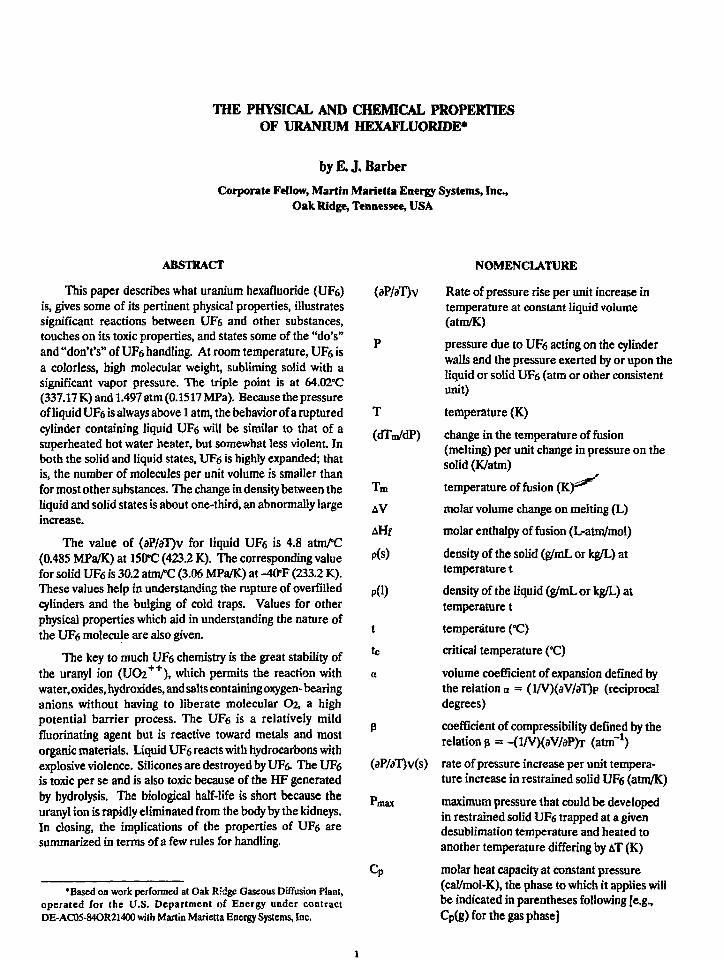
ABSTRACT
This paper describes what uranium hexafluoride (UF6) (dP/aT)vis, gives some of its pertinent physical properties, illustratessignificant reactions between UF6 and other substances,touches on its toxic properties, and states some of the "do's" _and "don't's" of UF6 handling. At room temperature, UF6 isa colorless, high molecular weight, subliming solid with asignificant vapor pressure. The triple point is at 64.02°C(337.17K)and 1.497 atm (0.1517 MPa). Because the pressureof liquid UF6 is always above 1 atm, the behavior of a rupturedcylinder containing liquid UFg will be similar to that of asuperheated hot water heater, but somewhat less violent. Inboth the solid and liquid states, UF6 is highly expanded; thatis, the number of molecules per unit volume is smaller thanfor most other substances. The change in density between theliquid and solid states is about one-third, an abnormally largeincrease.
The value of (aP/aT)v for liquid UF6 is 4.8 atnVC(0.485 MPa/K) at 150*C (423.2 K). The corresponding valuefor solid UF6 is 30.2 atm/C (3.06 MPa/K) at -40°F (233.2 K).These values help in understanding the rupture of overfilledcylinders and the bulging of cold traps. Values for otherphysical properties which aid in understanding the nature ofthe UFe molecule are also given.
The key to much UF6 chemistry is the great stability ofthe uranyl ion (UOi++), which permits the reaction withwater.oxides, hydroxides, andsaltscontainingoxygen-bearinganions without having to liberate molecular O2, a highpotential barrier process. The UF6 is a relatively mildfluorinating agent but is reactive toward metals and mostorganic materials. Liquid UFe reacts with hydrocarbons withexplosive violence. Silicones are destroyed by UF6. The UF6 (dP/aT)v(s)is toxic per se and is also toxic because of the HF generatedby hydrolysis. The biological half-life is short because the puranyl ion is rapidly eliminated from the body by the kidneys.In closing, the implications of the properties of UFe aresummarized in terms of a few rules for handling.
NOMENCLATURE
Rate of pressure rise per unit increase intemperature at constant liquid volume(atm/K)
pressure due to UF6 acting on the cylinderwalls and the pressure exerted by or upon theliquid or solid UF'6 (atm or other consistentunit)
T
(dTn/dP)
Tm
AV
AHf
P(S)
PG)
t
tc
a
temperature (K)
change in the temperature of fusion(melting) per unit change in pressure on thesolid (K/atm)
temperature of fusion (Kf^
molar volume change on melting (L)
molar enthalpy of fusion (L-atm/mol)
density of the solid (g/mL or kg/L) attemperature t
density of the liquid (g/mL or kg/L) attemperature t
temperature (°C)
critical temperature (°C)
volume coefficient of expansion defined bv
'Based on work performed at Oak Ridge Gaseous Diffusion Plant,operated for the U.S. Department of Energy under contractDE-AC05-84OR21400 with Martin Marietta Energy Systems, Inc.
the relation a = (l/V)(aV/aT)p (reciprocaldegrees)
coefficient of compressibility defined by therelation jj = -<l/V)(aV/aP)T (atnf1)
rate of pressure increase per unit tempera-ture increase in restrained solid UFg (atm/K)
maximum pressure that could be developedin restrained solid UF6 trapped at a givendesublimation temperature and heated toanother temperature differing by AT (K)
molar heat capacity at constant pressure(cal/mol-K), the phase to which it applies willbe indicated in parentheses following [e.g.,Cp(g) for the gas phase]

INTRODUCTION
This paper is intended to provide a description of whatUF6 is, some of its pertinent physical properties, illustrationsof the reactions between UF6 and other substances, someconcepts about UF6 reactions important to processing, andsome "do's" and "don't's" of UF6 handling and transporting.
At room temperature, UFe is a colorless, high molecularweight, nonpolar, subliming solid with significant, but less thanatmospheric vapor pressure. This statement immediatelyindicates that one will not be handed a bag containing UF6 ora bottle of liquid UF6 but that one will probably receive theUF6 in a metal tube sealed by a valve or valves. The contentsof the tube will not be subject to visual inspection and thereforemust be determined by analysis.
PHYSICAL PROPERTIES
Phase Diagram1
The phase diagram for pure UF6 is shown in Figure 1 inwhich the logarithm of the vapor pressure is given as a functionof the temperature. Only vapor exists in the region to the rightand below the continuous curve. The liquid exists to the rightof the dotted line and above the continuous line but to the leftof the critical-point temperature, above which temperaturethe liquid and vapor are indistinguishable. The liquid rangeis relatively long, and the critical pressure is relatively large,about 45.5 atm (4.61 MPa), for a material of this class. As willbe emphasized by others, UF6 storage cylinders are notdesigned to withstand such pressures. The area to the left ofthe dashed and continuous curves represents conditions underwhich the solid UF6 exists.
Note that the sublimation temperature is below the triplepoint. This has implications for processing because the
DWG. NC. K/C-S2-230I
100.00)
10.000
1,000
100
CRITICAL POINT: 230.2°C45.5 atm
- SOLID
TRIPLE POINT: 64.02°C1.497 atm
'SUBLIMATION POINT: 56.4°C1.00 atm
VAPOR
OLIVER, MILTON. AND GRISARD (REF. 1)
C A L c U f f i . = V l - 0.0439 deg /atmdP AH f
I I I I I I I I I I I I I I I I I I I I I I I I
pressure must be above 1.5 atm (0.152 MPa) and thetemperature above 64°C (337 K) for UF6 to be handled as aliquid. Thus, any process using liquid UF6 will be subject toleakage of the UF6 to the atmosphere through any holes. Also,because the pressure of liquid UF6 is always above 1 atm, thebehavior of a ruptured cylinder may be similar to that of asuperheated hotwaterheater, although somewhat less violent.Transfers below 1.5 atm or below 64*C involve moving vaporthatisproducedbysublimationandremovedbydesublimationin a cooled trap.
Density of UF6
The UF6 is a relatively expanded liquid and solid; that is,the number of molecules per unit volume of liquid and solidare relatively fewer than in most other materials. Still thedensities are quite large, as seen from Figure 2 in which thedensities of solid and liquid UF6 are shown as functions oftemperature. Equations expressing the density of the solidand liquid as a function of temperature are given below.Equation 1 comes from refs. 2 and 3, Equation 2 from ref. 4,and Equation 2a from ref. 5.
P(s) = 5.194-0.0051681, g/mL, (1)
,0.5p (1) = 1.670 + 0.15203 (230.2 -1)°°, g/mL, (2)
or
p(l) = 2.0843-0.00311 + 0.3710 (2302-t)0 3 0 4 5 ,g/mL, (2a)
Equation 2 is probably more accurate near the triplepoint, and Equation 2a is more accurate near the critical point
OMT6. NO. K/G-tt-MMlu)
6.0
5.0 -
,4.0 -
oS 3.0
1.0
p{«) * 5.194
SOLID UFg
— or
I
- 0.005168t
P(0
PHI
= 1.670
= 2.0843
1
t15203(tc-t)0-5
- 0.00311 + 0.3710(tc
LIQUID U F g ^ V
1 1
.,,0.3045
\
\23O.2°C
50 100 150TEMPERATURE. °C
200 250 50 100 150TEMPERATURE. °C
200 250
Figure 1. UF6 phase diagram. Figure 2. Density of UF6.
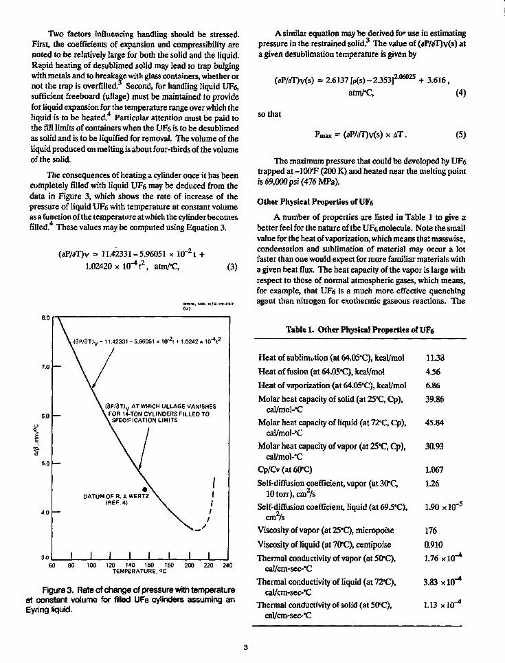
Two factors influencing handling should be stressed.First, the coefficients of expansion and compressibility arenoted to be relatively large for both the solid and the liquid.Rapid heating of desublimed solid may lead to trap bulgingwith metals and to breakage with glass containers, whether ornot the trap is overfilled. Second, for handling liquid UF&sufficient freeboard (ullage) must be maintained to providefor liquid expansion for the temperature range over which theliquid is to be heated.4 Particular attention must be paid tothe fill limits of containers when the UFe is to be desublimedas solid and is to be liquified for removal. The volume of theliquid produced on melting is about four-thirds of the volumeof the solid.
The consequences of heating a cylinder once it has beencompletely filled with liquid UFe may be deduced from thedata in Figure 3, which shows the rate of increase of thepressure of liquid UF6 with temperature at constant volumeas a function of the temperature atwhich the cylinder becomesfilled.4 These values may be computed using Equation 3.
(aP/aT)v = 11.42331-5.96051 x 10'1.02420 x lO"4!2, atm/°C,
,-2 t +(3)
DWG. NO. K/G-7V-I37
8.0
7.0
6.0
5.0
4.0
3.0
t (3P/3T)V = 11.42331 - 5.96051 x 10'2t + 1.0242 x 10*4t2
V AT WHICH ULLAGE VANISHESL FOR 14-TON CYLINDERS FILLED TO
I SPECIFICATION LIMITS
DATUM OF R. J. WERTZ(REF.4)
I I I I J I I60 80 100 120 140 160 180
TEMPERATURE. °C200 220 240
Figure 3. Rate of change of pressure with temperatureat constant volume for filled UF6 cylinders assuming anEyring liquid.
A similar equation maybe derived for use in estimatingpressure in the restrained solid.3 The value of (aP/aT)v(s) ata given desublimation temperature is given by
(aP/aT)v(s) = 2.6137 [p(s) - 2.353]206025 + 3.616,
so that
atnVC,
= (aP/aT)v(s)xAT.
(4)
(5)
The maximum pressure that could be developed by UF6trapped at -100*F (200 K) and heated near the melting pointis 69,000 psi (476 MPa).
Other Physical Properties of UFe
A number of properties are listed in Table 1 to give abetter feel for the nature of the UF6 molecule. Note the smallvalue for the heat of vaporization, which means that masswise,condensation and sublimation of material may occur a lotfaster than one would expect for more familiar materials witha given heat flux. The heat capacity of the vapor is large withrespect to those of normal atmospheric gases, which means,for example, that UF6 is a much more effective quenchingagent than nitrogen for exothermic gaseous reactions. The
Table 1. Other Physical Properties ofUF6
Heat of sublimation (at 64.05°C), kcal/mol
Heat of fusion (at 64.050C), kcal/mol
Heat of vaporization (at 64.05°C), kcal/mol
Molar heat capacity of solid (at 25"C, Cp),cal/mol-°C
Molar heat capacity of liquid (at 72°C, Cp),cal/mol-°C
Molar heat capacity of vapor (at 25°C, Cp),cal/mol-'C
Cp/Cv(at60»C)
Self-diffusion coefficient, vapor (at 30*C,10torr),cm2/s
Self-diffusion coefficient, liquid (at 69.5°C),cm2/s
Viscosity of vapor (at 25'C), micropoise
Viscosity of liquid (at 70*0), centipoise
Thermal conductivity of vapor (at 50°C),cal/cm-sec-°C
Thermal conductivity of liquid (at 72*C),cal/cm-sec-8C
Thermal conductivity of solid (at 50°C),cal/cm-scc-*C
11.33
4.56
6.86
39.86
45.84
30.93
1.067
1.26
1.90 xlO~"5
176
0.910
1.76 xlO-*
3.83 xlO"4
1.13 x 10"4
combination of low surface tension, low viscosity, and highdensity leads one to expect quite small droplets and thusstreaming in distillation columns at very low throughputs withsome resultant designproblems,suchashowtoeasureuniformwetting and flow throughout a column. Attention is called tothe apparent discrepancy in the value of the triple point givenin Figure 1 and Table 1 of 0.03'C. The value of 64.02'C isobtained experimentally by boiling the UF6 under a nitrogenatmosphere. The dissolved nitrogen in the liquid UF6depresses the triple point by 0.03°C; thus, the triple point underthe orthobaric pressure is 64.05°C.
CHEMICAL PROPERTIES
Chemistry of UF6 (ref. 6)
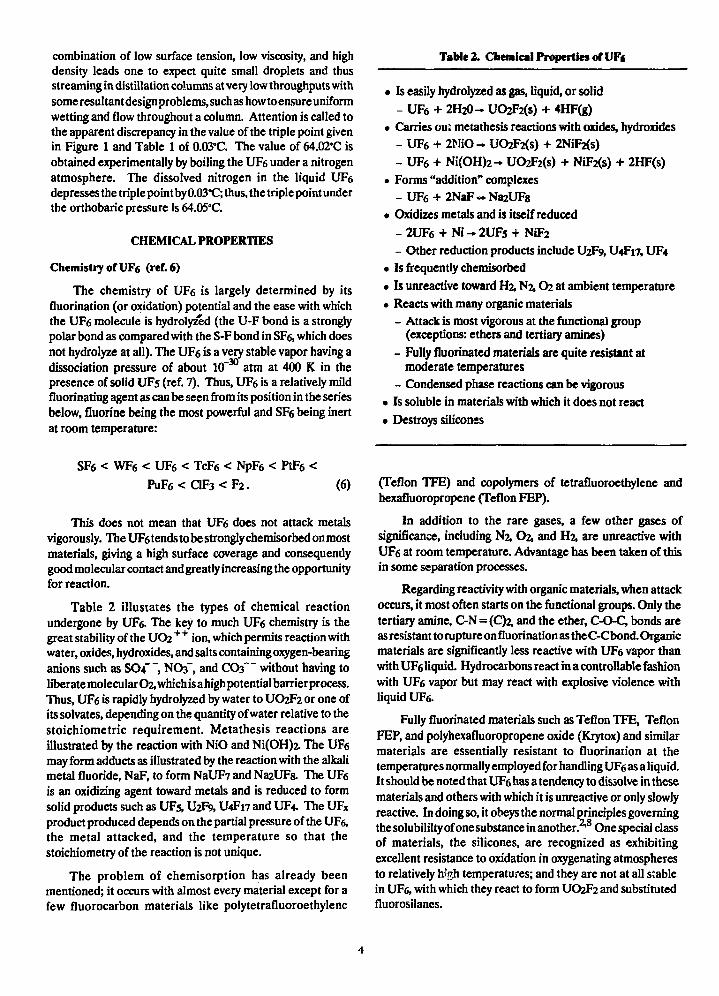
The chemistry of UF6 is largely determined by itsfluorination (or oxidation) potential and the ease with whichthe UF6 molecule is hydrolyzed (the U-F bond is a stronglypolar bond as compared with the S-F bond in SF& which doesnot hydrolyze at all). The UF6 is a very stable vapor having adissociation pressure of about 10"30 atm at 400 K in thepresence of solid UF5 (ref. 7). Thus, UF6 is a relatively mildfluorinating agent as can be seen from its position in the seriesbelow, fluorine being the most powerful and SF6 being inertat room temperature:
Table 2. Chemical Properties of VFt
• Is easily hydrolyzed as gas, liquid, or solid
- UF6 + 2H2O- UO2F2(s) + 4HF(g)
• Carries oui metathesis reactions with oxides, hydroxides
- UF6 + 2MiO- UO2F2(s) + 2NiF2(s)
- UF6 + Ni(OH)2-> UO2F2(s) + NiF2(s) + 2HF(s)• Forms "addition" complexes
- UF6 + 2NaF « Na2UFs• Oxidizes metals and is itself reduced
- 2UF6 + Ni - 2UFs + NiF2
- Other reduction products include U2F9, U4F17, UF4
• Is frequently chemisorbed
• Is unreactive toward H2, N2,02 at ambient temperature
• Reacts with many organic materials- Attack is most vigorous at the functional group
(exceptions: ethers and tertiary amines)
- Fully fluorinated materials are quite resistant atmoderate temperatures
- Condensed phase reactions can be vigorous
• Is soluble in materials with which it does not react
• Destroys silicons
SF6 < WF6 < UF6 < TcF6
P u F 6 < C l F 3 < F 2 .
PtF6
(6)
This does not mean that UF6 does not attack metalsvigorously. TheUF6tendstobestronglychemisorbedonmostmaterials, giving a high surface coverage and consequentlygood molecular contact and greatly increasing the opportunityfor reaction.
Table 2 illustates the types of chemical reactionundergone by UF6. The key to much UF6 chemistry is thegreat stability of the U O 2 + + ion, which permits reaction withwater, oxides, hydroxides, and salts containing oxygen-bearinganions such as SO4 , NO3-, and CO3 without having toliberate molecular O2, which isahighpotentialbarrierprocess.Thus, UF6 is rapidly hydrolyzed by water to UO2F2 or one ofits solvates, depending on the quantity of water relative to thestoichiometric requirement. Metathesis reactions areillustrated by the reaction with NiO and Ni(OH)i The UF6may form adducts as illustrated by the reaction with the alkalimetal fluoride, NaF, to form NaUF7 and Na2UFs. The UF6is an oxidizing agent toward metals and is reduced to formsolid products such as UF5, U2F9, U4F17 and UF4. The UFX
product produced depends on the partial pressure of the UF6,the metal attacked, and the temperature so that thestoichiometry of the reaction is not unique.
The problem of chemisorption has already beenmentioned; it occurs with almost every material except for afew fluorocarbon materials like polytetrafluoroethylene
(Teflon TFE) and copolymers of tetrafluoroethylene andhexafluoropropene (Teflon FEP).
In addition to the rare gases, a few other gases ofsignificance, including N& O2, and H2, are unreactive withUF6 at room temperature. Advantage has been taken of thisin some separation processes.
Regarding reactivity with organic materials, when attackoccurs, it most often starts on the functional groups. Only thetertiary amine, C-N=(C)2, and the ether, C-O-C, bonds areas resistant to rupture on fluorination as the C-Cbond. Organicmaterials are significantly less reactive with UF6 vapor thanwith UF6 liquid. Hydrocarbons react in a controllable fashionwith UFe vapor but may react with explosive violence withliquid UF6.
Fully fluorinated materials such as Teflon TFE, TeflonFEP, and polyhexafiuoropropene oxide (Krytox) and similarmaterials are essentially resistant to fluorination at thetemperatures normally employed for handling UF6 as a liquid.It should be noted that UFg has a tendency to dissolve in thesematerials and others with which it is unreactive or only slowlyreactive. In doing so, it obeys the normal principles governingthe solubililty of onesubstance in another.2"8 One special classof materials, the silicones, are recognized as exhibitingexcellent resistance to oxidation in oxygenating atmospheresto relatively high temperatures; and they are not at all stablein UF6, with which they react to form UO2F2 and substitutedfluorosilanes.

ToxicityofUFe (ref.9)
Elemental uranium is a highly toxic material on an acutebasis. Uranium hexafluoride vapor is toxic per se, producingsome kidney damage and hydrolyzing to produce HF, whichis itself a regulated toxic substance. The threshold limit value(TLV), which is the allowable 8-hour exposure level forindustrial workers, is 3 ppm for HF. This value of the TLV forHF translates into a TLV for UF6 of 0.75 ppm (volume basis)based on the fact that one UF6 molecule produces fourmolecules of HF as the essentially instantaneous hydrolysis inthe atmosphere occurs. Fortunately, the UO2++ ion has ashort biological half-life, and any UO2F2 absorbed throughthe lungs or injested orally is rapidly eliminated from the bodyby kidney action, thus minimizing the damage.
HANDLING RULES:SOME DO's AND DONT's WITH VF6
A few rules for handling UF6 can be based on theimplications of the properties of the compound:
1. Handle UF6 in a sealed system having vacuumcapability to aid in transfers. Liquid transfers are possible ina system that can be operated above about 1.5 atm(0.152 MPa) and 64.05°C (337.20 K).
2. Keep UF6 away from moisture; otherwise, it will belost from the gas phase as UO2F2.
3. Don't breathe UF6 or its reaction products. Getrespiratory protection before handling heated containers;handle them preferably in a fume hood.
4. Leave at least 40% ullage in cold traps.
5. Don't hook UF6 cylinders directly to vacuum pumps.
6. Remember that liquid UF6 and organic materials,other than fluoroplastics, can react violently. (Do not heatcylinders known to contain UF6 and liquid hydrocarbons.)
SUMMARY
In summary, be reminded that the properties of UF6determine howit must be handled and makedirect observationimpossible. To determine that the material in a container isUF6, one must use other instruments in addition to a scale.Because of the very large volume expansion of UF6 uponmelting, diligence must be exercised in filling cylinders inwhich the UF6 is partially solidified. A cylinder of liquifiedUF6 with no ullage is potentially the equivalent of asuperheated hot water heater, not just a hydraulicallyoverpressurized cylinder. Finally, UF6 can be handled safelyby careful attention to the suggested precautions.
REFERENCES
1. G. D. Oliver, H. T. Milton and J. W. Grisard, "TheVapor Pressure and Critical Constants of UF6,"/. Am. Chem.Soc. 75,2827-9 (1953).
2. R. DeWitt, Uranium Hexafluoride: A Survey of thePhysico-Chemical Properties, GAT-280, Goodyear AtomicCorporation, Portsmouth, Ohio, Aug. 12,1960.
3. E. J. Barber, Estimation of Pressures Developed byRestrained Solid Uranium Hexafluoride, K/ET-307, UnionCarbide Corporation, Nuclear Division, Oak Ridge GaseousDiffusion Plant, Sept. 14,1979.
4. E. J. Barber, Relationship of Pressure to TemperatureRise in Overfilled Cylinders, K/ET-194, Union CarbideCorporation, Nuclear Division, Oak Ridge GaseousDiffusion Plant, May 18,1979.
5. R. J. Wertz and W. D. Hedge, Density of LiquidUranium Hexafluoride, K-1466, Union Carbide Corporation,Nuclear Division, Oak Ridge Gaseous Diffusion Plant,Feb. 1,1965.
6. J. J. Katz and E. Rabinowitch, The Chemistry ofUranium. Part I: The Element, Its Binary and RelatedCompounds, National Nuclear Energy Series, Division VIII,Vol. 5, McGraw-Hill Book Company, New York, 1951.
7. J. M. Leitnaker, Thermodynamic Data for UraniumFluorides, K/PS-352, Union Carbide Corporation, NuclearDivision, Oak Ridge Gaseous Diffusion Plant, March 1983.
8. J. H. Hildebrand and R. L. Scott, The Solubility ofNonelectrolytes, Third Edition, American Chemical SocietyMonograph Series, Reinhold Publishing Corporation, NewYork, 1950.
9. N. I. Sax, Dangerous Properties of Industrial Materials,Sixth Edition, Van Nostrand Reinhold Company, New York,1984, p. 2711.
The submitted manuscript has been authored by acontractor oFtheU.S. Go vernmeni under Contract No.DE-AC05-84OR21400. Accordingly, the U.S.Government retains a nonexctustve, royalty-treelicense to publish or reproduce the published form orthis contribution, or to allow others to do so for U.S.Government Purposes.

ACUTE TOXICITY OF URANIUM HEXAFLUORIDE,URANYL FLUORIDE AND HYDROGEN FLUORIDE
Robert A. JustProcess Engineering
Oak Ridge National Laboratory1
Oak Ridge, Tennessee, U.S.A.
ABSTRACT
Uranium hexafluoride (UFS) released into theatmosphere will react rapidly with moisture in theair to form the hydrolysis products uranylfluoride (U02F2) and hydrogen fluoride (HF).Uranium compounds such as UF6 and U02F2 exhibitboth chemical toxicity and radiological effects,while HF exhibits only chemical toxicity. Thispaper describes the development of a methodologyfor assessing the human health consequences of aknown acute exposure to a mixture of UFS, U02F2,and HF.
1. INTRODUCTION
Uranium hexafluoride (UFS) released into theatmosphere will react rapidly with moisture in theair to form the hydrolysis products uranylfluoride (U02F2) and hydrogen fluoride (HF). Thecorrosive HF vapor formed by this reaction has apungent odor and is very irritating to the skinand mucous membranes. The soluble uraniumcompounds, U02F2 and UF6, exhibit both chemicaltoxicity and radiological effects.
Individuals exposed to these toxic materials maysuffer varying health effects depending upon theconcentration of the toxicant, the duration of theexposure and many other factors. For example, anaccident evaluation may require consideration ofthe ability of personnel to escape quickly, thevariation in the spatial concentration of thetoxicant(s), and the physical activity level atthe time of exposure. Although these factors maybe important when evaluating the hazard associatedwith an accidental UFS release, the informationpresented in this report does not attempt toaccount for all the many variables that may needto be considered in a hazard evaluation. Rather,this report focuses on predicting the healtheffects given the exposure duration and toxicantconcentration.
2. CHEMICAL TOXICITY OF UFe, HF and UO2F2
In 1980 a group of experts In the field ofchemical toxicity of soluble uranium and HF wereasked to apply known data and make their best
'•Operated by Martin Marietta Energy Systems,Inc. for the U. S. DEPARTMENT OF ENERGY underContract No. DE-AC05-84OR21400.
judgments about the toxicological effects ofpostulated exposures to soluble uranium and HF.This information was then used to developpreliminary Design and Analysis guidelines forestimating the toxicity of soluble uranium and HF.
A review of the information obtained during thedevelopment of the preliminary Design andAnalysis guidelines indicated a lack of directlyapplicable data for assessing the consequences ofacute UFa, U02F2 and HF exposures. Therefore, itwas concluded that it would be desirable to obtainadditional data on the consequences of acuteexposures to UFe and UF6 hydrolysis products. TheU. S. Department of Energy (DOE) sponsored aseries of animal toxicity experiments at theUniversity of Rochester in order to provideadditional data to support accident assessments -̂U. S. UFS handling facilities.
The primary objective of the toxicity experimentswas the development of a procedure for evaluatingthe consequences of acute exposures to mixtures ofUF6 and UFS hydrolysis products. This goal wasachieved by completing the following tasks:
(1) determination of the lethal exposuresusceptibility of rats and guinea pigs toUFe and the UFg hydrolysis products U02F2and HF;
(2) definition and measurement of delayedeffects of uranium and fluorine in animalsurvivors of UF6, U02F2 and HFexposures; and
(3) prediction from the results of the animalexperiments, minimum exposure levels forhumans of UFe and U02F2/HF mixtures whichwill result in significant physiologicaldamage for short periods of exposure.
In late 1983 the experimental work was completedand documented in a report submitted by theUniversity of Rochester to Martin Marietta EnergySystems, Inc.(l) As indicated in Table 1, a totalof 66 experiments were conducted utilizing 511rats and 78 guinea pigs for exposure durationsranging from 2 to 60 minutes. The results of theUniversity of Rochester rat and guinea pigexperiments are summarized in Table 2.
A "Delphi" panel of toxicologists was forned tointerpret the experimental results. J. B. Hursh,L. J. Leach, and P. E. Morrow of the University ofRochester and M. E. Wrenn of the University ofUtah were asked to develop independent,preliminary estimates of the toxicity of UF,hydrolysis products. These prelininary toxicityestimates were presented at a meeting where each
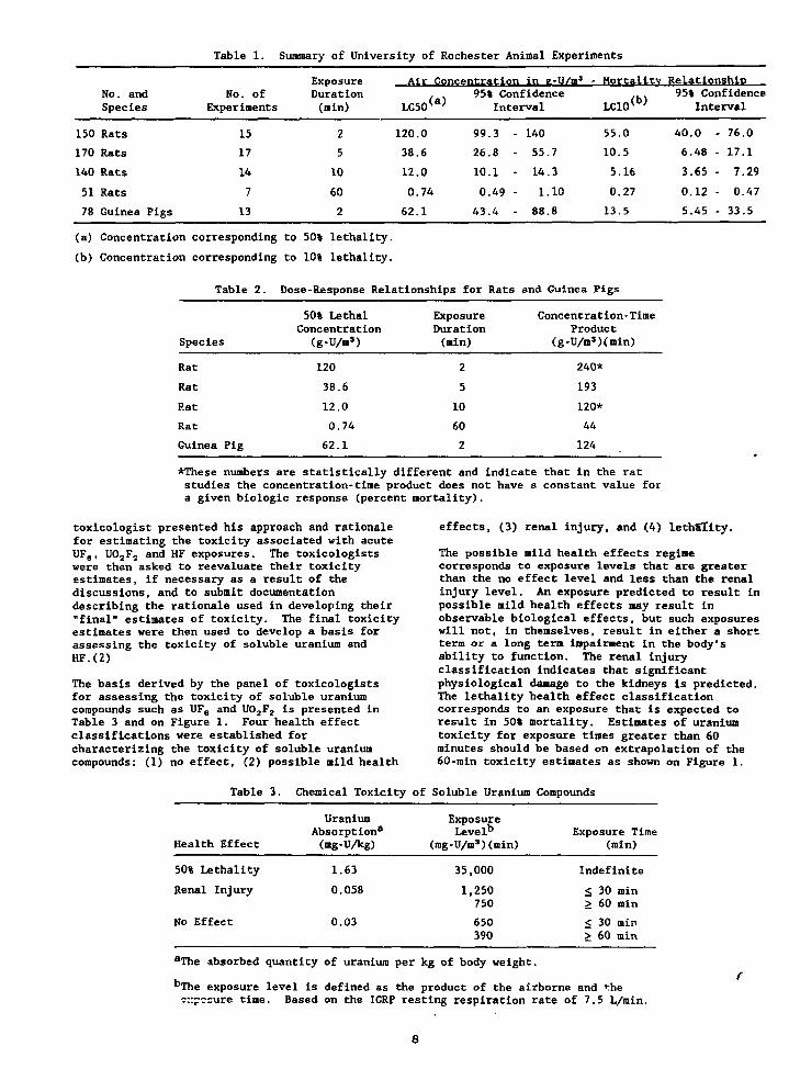
Table 1. Summary of University of Rochester Animal Experiments
No. andSpecies
150 Rats
170 Rats
140 Rats
51 Rats
78 Guinea Pigs
No. ofExperiments
15
17
14
7
13
ExposureDuration(min)
2
5
10
60
2
Air Concentration in e-U/m3
LC50(a)
120.0
38.6
12.0
0.74
62.1
95% ConfidenceInterval
99.3 - 140
26.8 - 55.7
10.1 - 14.3
0.49 - 1.10
43.4 - 88.8
- Mortality
LC10(b)
55.0
10.5
5.16
0.27
13.5
Relationship95% Confidence
Interval
40.0 - 76.0
6.48 - 17.1
3.65 - 7.29
0.12 - 0.47
5.45 - 33.5
(a) Concentration corresponding to 50% lethality.
(b) Concentration corresponding to 10% lethality.
Table 2. Dose-Response Relationships for Rats and Guinea Pigs
Species
Rat
Rat
Rat
Rat
Guinea Pig
50% LethalConcentration
(g-U/ns)
120
38.6
12.0
0.74
62.1
ExposureDuration(nin)
2
5
10
60
2
Concentration-TimeProduct
(g-U/ms)(min)
240*
193
120*
44
124
*These numbers are statistically different and indicate that in the ratstudies the concentration-time product does not have a constant value fora given biologic response (percent mortality).
toxicologist presented his approach and rationalefor estimating the toxicity associated with acuteUFg, U02F2 and HF exposures. The toxicologistswere then asked to reevaluate their toxicityestimates, if necessary as a result of thediscussions, and to submit documentationdescribing the rationale used in developing their"final" estimates of toxicity. The final toxicityestimates were then used to develop a basis forassessing the toxicity of soluble uranium andHF.(2)
The basis derived by the panel of toxicologistsfor assessing the toxicity of soluble uraniumcompounds such as UF6 and U02F2 is presented inTable 3 and on Figure 1. Four health effectclassifications were established forcharacterizing the toxicity of soluble uraniuncompounds: (1) no effect, (2) possible mild health
effects, (3) renal injury, and (4) lethSlity.
The possible mild health effects regimecorresponds to exposure levels that are greaterthan the no effect level and less than the renalinjury level. An exposure predicted to result inpossible mild health effects may result inobservable biological effects, but such exposureswill not, in themselves, result in either a shortterm or a long tern impairment in the body'sability to function. The renal injuryclassification indicates that significantphysiological damage to the kidneys is predicted.The lethality health effect classificationcorresponds to an exposure that is expected toresult in 50% mortality. Estimates of uraniumtoxicity for exposure times greater than 60minutes should be based on extrapolation of the60-rain toxicity estimates as shown on Figure 1.
Table 3. Chemical Toxicity of Soluble Uranium Compounds
Health Effect
UraniumAbsorption3
(mg-U/kg)
ExposureLevel0
(mg-U/m3)(min)Exposure Time
(min)
50% Lethality
Renal Injury
No Effect
1.63
0.058
0.03
35,000
1,250750
650390
Indefinite
< 30 min> 60 min
< 30 rain> 60 min
aThe absorbed quantity of uranium per kg of body weight.
bThe exposure level is defined as the product of the airborne and thec::pc=ure time. Based on the ICRP resting respiration rate of 7.5 L/min.
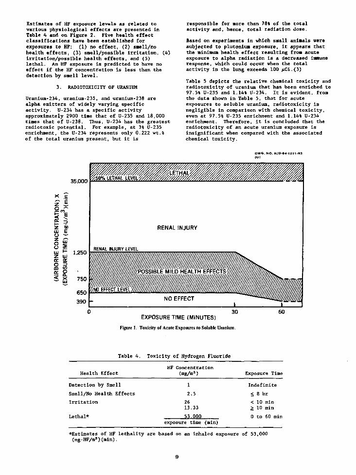
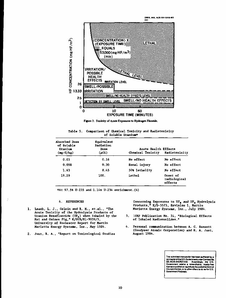
Estimates of HF exposure levels as related tovarious physiological effects are presented inTable 4 and on Figure 2. Five health effectclassifications have been established forexposures to HF: (1) no effect, (2) sue1I/nohealth effects, (3) snell/possible irritation, (4)irritation/possible health effects, and (5)lethal. An HF exposure is predicted to have noeffect if the HF concentration is less than thedetection by sue11 level.
3. RADIOTOXICITY OF URANIUM
Uranium-234, uranium-235, and uranium-238 arealpha emitters of widely varying specificactivity. U-234 has a specific activityapproximately 2900 time that of U-235 and 18,000times that of U-238. Thus, U-234 has the greatestradiotoxic potential. For example, at 3% U-235enrichment, the U-234 represents only 0.222 wt.%of the total uranium present, but it is
responsible for more than 78% of the totalactivity and, hence, total radiation dose.
Based on experiments in which saall animals weresubjected to plutoniun exposure, it appears thatthe nininun health effect resulting from acuteexposure to alpha radiation is a decreased inmuneresponse, which could occur when the totalactivity in the lung exceeds 100 >iCi.(3)
Table 5 depicts the relative chemical toxicity andradiotoxicity of uranium that has been enriched to97.5% U-235 and 1.14% U-234. It is evident, fromthe data shown in Table 5, that for acuteexposures to soluble uranium, radiotoxicity isnegligible in comparison with chemical toxicity,even at 97.5% U-235 enrichment and 1.14% U-234enrichment. Therefore, it is concluded that theradiotoxicity of an acute uranium exposure isinsignificant when compared with the associatedchemical toxicity.
DWG. NO. K/G-t4-12l1-R3
35,000
X
101
ccH-LUOoo111z(Xo
AIR
B
c1nE\
LUcr
X
1,250
750
650
390
RENAL INJURY
RENAL INJURY LEVEL
POSSIBLE MILD HEALTH EFFEC
EXPOSURE TIME (MINUTES)
Figure 1. Toxicity of Acute Exposures to Soluble Uranium.
60
Table 4. Toxicity of Hydrogen Fluoride
Health Effect
Detection by Smell
Smell/No Health Effects
Irritation
Lethal*
HF Concentration(mg/m3)
1
2.5
2613.33
53.000exposure time (min)
Exposure Time
Indefinite
< 8 hr
< 10 min> 10 min
0 to 60 min
^Estimates of HF lethality are based on an inhaled exposure of 53,000(mg-HF/ms)(min).
•WC. NO. K/G-M-IZtl-ltl("I
I00
rg
ooou.X 13.33
2.510
IRRITATION/POSSIBLEHEALTH
BY SMELL LEVEL SMELL/NO HEALTH EFFECTS
0 10 60EXPOSURE TIME (MINUTES)
Figure 2. Toxicity of Acute Exposures to Hydrogen Fluoride.
Table 5. Comparison of Chemical Toxlclty and Radlotoxlcityof Soluble Uranium*
Absorbed Doseof SolubleUranium(mg-UAg)
EquivalentRadiation
DoseOiCl)
Acute Health EffectsChemical Toxicity Radiotoxicity
0.03
0.058
1.63
19.29
0.16
0.30
8.45
100.
No effect
Renal injury
50% lethality
Lethal
No effect
No effect
No effect
Onset ofradiologicaleffects
*At 97.5% U-235 and 1.14% U-234 enrichment.(4)
4. REFERENCES
1. Leach, L. J., Gelein and R. M., et.al., "TheAcute Toxicity of the Hydrolysis Products ofUranium Hexafluoride (UFe) when Inhaled by theRat and Guinea Pig," K/SUB/81-9039/3,University of Rochester Report for MartinMarietta Energy Systems, Inc., May 1984.
2. Just, R. A., "Report on Toxicological Studies
Concerning Exposures to UF, and UFe HydrolysisProducts," K/D-5573, Revision 1, MartinMarietta Energy Systems, Inc., July 1984.
3. ICRP Publication No. 31, "Biological Effectsof Inhaled Radionuclides."
4. Personal communication between A. C. Bassett(Goodyear Atomic Corporation) and R. A. Just,August 1984.
Th» submimd manuscript has btwi authored by acontractor of th*U.S.GovtmnwnundtrConnct No.DE-AC0544OR21400. Accordingly, ty* U.S.Govtmmtnt retain* a nontxduiiv*. royalty-Ire*KoinM to publish or mproduc* th» published farm ofthis contribution, or to allow othtrs » do so lor U SGovemmentPurposfts.
10
An Experimental Study on Heat Transfer of A UFg-Filled Vessel
Mitsutoshi Suzuki, Yoshiaki Ohkuma1, Shuji Ikou,Kaoru Shimizu, Teruo Akiyama and Yumio Yato
Technology Development Section, Uranium Enrichment Development Division,Tokai Works, Power Reactor and Nuclear Fuel Development Corporation,
4-33 Muramatsu, Tokai-mura, Naka-gun, Ibaraki-ken, JAPAN
ABSTRACT
Thermal tests for a bare vessel filled with uraniumhexafluoride were conducted at Tokai Works of PNCduring August 1987, for a better understanding ofheat transfer phenomena in a hex cylinder. Theequipment for thermal tests consists of a 270 mmin diameter, 1400 mm long and 30 mm thick carbonsteel test cylinder encased with a 20 kW electricheater and measuring sensors. The test cylinderwas filled with about 110 kg of uranium hexafluoride,which amounted to 95% in volume of the test cylinderwhen the inner uranium hexafluoride temperaturebecame 120°C. The temperature of the heater sur-face was controlled by a PID controller in the rangefrom 80 to 400°C. The setup was equipped witha capacitance manometer to measure inner pressureof the test cylinder and 28 conventional seathedthermocouples attached to various places of boththe equipment and inner uranium hexafluoride, whichallowed us to observe the phase changes of inneruranium hexafluoride as a function of time. Basedon the experimental observation, we proposed aheat transfer model suitable for numerical analysisand derived the values related to heat transfer ina cylinder filled with uranium hexafluoride by usinga TRUMP code.
INTRODUCTION
The main purpose of thermal tests for a barevessel filled with uraniam hexafluoride is to derivevalues related to the heat transfer, such as theheat transmitted to inner uranium hexafluoride, theheat transfer coefficient between the cylinder mate-rial and uranium hexafluoride, and the apparentthermal conductivities of solid and liquid uraniumhexafluoride. Another purpose is to observe the phasechanges of uranium hexafluoride in the test cylinderas a function of time to construct a heat transfermodel suitable for numerical analysis. These experi-mental findings will contribute to determine analyti-cally if the 48Y cylinders would hydrostatically rup-ture and the time available for fire fighting beforethe incident occurred.
EXPERIMENTAL
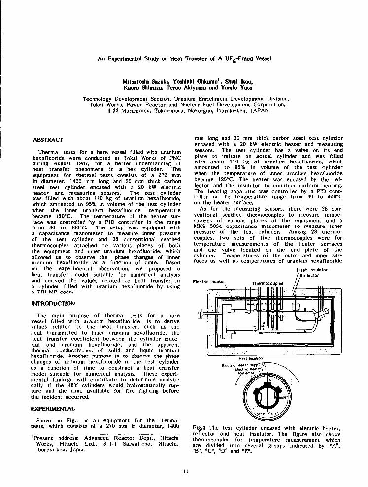
Shown in Fig. 1 is an equipment for the thermaltests, which consists of a 270 mm in diameter, 14001 Present address: Advanced Reactor Dept., Hitachi
Works, Hitachi Ltd., 3-1-1 Saiwai-cho, Hitachi,Ibaraki-ken, Japan
mm long and 30 mm thick carbon steel test cylinderencased with a 20 kW electric heater and measuringsensors. The test cylinder has a valve on its endplate to imitate an actual cylinder and was filledwith about 110 kg of uranium hexafluoride, whichamounted to 95% in volume of the test cylinderwhen the temperature of inner uranium hexafluoridebecame 120°C. The heater was encased by the ref-lector and the insulator to maintain uniform heating.This heating apparatus was controlled by a PID cont-roller in the temperature range from 80 to 400cCon the heater surface.
As for the measuring sensors, there were 28 con-ventional seathed thermocouples to measure tempe-ratures of various places of the equipment and aMKS 5034 capacitance manometer to measure innerpressure of the test cylinder. Among 28 thermo-couples, two sets of five thermocouples were fortemperature measurements of the heater surfacesand the valve located on the end plate of thecylinder. Temperatures of the outer ard inner sur-faces as well as temperatures of uranium hexafluoride
Heat insulatorReflector
Electric heater
Fig.l The test cylinder encased with electric heater,reflector and heat insulator. The figure also showsthermocouples for temperature measurement whichare divided into several groups indicated by "A","B", "C", "D" and "E".
11

in the cylinder were measured by the rest 18 ther-mocouples. These 18 thermocouples were dividedinto several groups to measure the radial temperaturedistribution. We labeled the groups measuring thelower and the upper parts on the vertical centerline as "A" ("E") and "D", respectively. Labels"B" and "C" were used for the groups measuringthe parts with angles of 90° and 45° to the verticalcenter line. These labels had additional sufficesto indicate radial positions. The outer and innersurfaces of the test cylinder were indicated by thesuffices "1" and "2" respectively. Indicated by"3", "4", "5" were 3 mm, 23mm and 43mm inwardsaway from the inner surface.
Fig. 2 shows the safety system of the testequipment, which consists of a large volume pressurerelease tank along with a safety valve and a rupturedisc whose working pressures are 3.2 and4.2 kg/cm G, respectively. This figure also showsthe data logger using a PC 9801 personal computerwhich facilitates data acquisition of all the 29 mea-surements in every three seconds.
Because of its large capacity, the heater tempera-ture went up rather fast and reached the desiredlevel in 7 to 8 minutes after supplying power withinthe temperature range from 200 to 400°C. In themean time, we observed that the pressure reachedand stayed at the triple point of uranium hexafluo-ride in a certain period and then rose rapidly.Since we observed that the inner pressure reachedand stayed at the triple point vapor pressure ofuranium hexafluoride in a certain period and thenrose rapidly, we determined the timing to turn offthe heater switch after repeated trial operationsof the equipment.
During August 1987, the total of 11 runs of thermaltests were carried out as shown in Table 1. InCase 1, the initial state of solid uranium hexafluoridewas considered to be in a cylindrical form, becauseit was the state right after 110 kg of gaseous ura-nium hexafluoride was first transferred into thecold test cylinder. Tests made after liquefyingand purifying uranium hexafluoride are the Cases2, 3, and 4, where we set the maximum temperatureof the heater for 200, 300 and 400°C, respectively.
RESULTS
• Shown in the above of Fig.3 is a typical exampleof the results in our thermal tests. We can seethat even after the heater surface reaches the pre-determined temperature, 200°C in this case, theinner pressure goes up rather slowly and then shows
, Safety valve
Rupture disc
Table 1. Conditions of thermal tests carried outin August 1987.
Pressure relief tank
• N £1/\Manometer fr g) X)~i Test cylinder
U«t .Heater
PC 9801
Data,processor
Thermocouples
Fig.2 Safety devices for thermal tests and dataacquisition system using a PC9801 processor whichallows to acquire 29 measurements in every 3 seconds.
Case
No.
1
2 -
2 -
2 -
2 -
3 -
3 -
3 -
4 -
4 -
4 -
1
2
3
4
1
2
3
1
2
3
UFecondition Thermal condition
weight heater heating heatinginitial form temp. rate time
(k9) CC) CC/min) (min.)
112
107
107
107
-cylinder
-cylinder
-cylinder
200
300
400
36
27
36
36
43
42
56
60
60
26
21
20
10
17
25
4000
20 40 60 80T I M E (min)
100 120
Fig.3 Typical examples of experimental results.The above figure shows both the inner pressure changeand the temperature changes as a function of timein Case 2-4. The result in Case 4-1 is shown below.Temperature measurements were shown at differentpositions from each other.
12
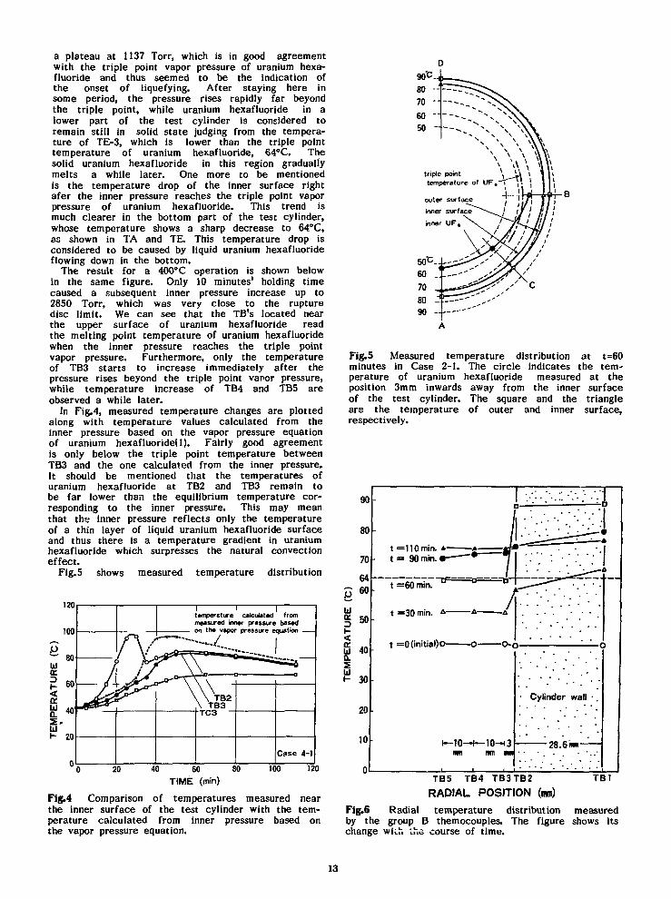
a plateau at 1137 Torr, which is in good agreementwith the triple point vapor pressure of uranium hexa-fluoride and thus seemed to be the indication ofthe onset of liquefying. After staying here insome period, the pressure rises rapidly far beyondthe triple point, while uranium hexafluoride in alower part of the test cylinder is considered toremain still in solid state judging from the tempera-ture of TE-3, which is lower than the triple pointtemperature of uranium hexafluoride, 64°C. Thesolid uranium hexafluoride in this region graduallymelts a while later. One more to be mentionedis the temperature drop of the inner surface rightafer the inner pressure reaches the triple point vaporpressure of uranium hexafluoride. This trend ismuch clearer in the bottom part of the test cylinder,whose temperature shows a sharp decrease to 64°C,as shown in TA and TE. This temperature drop isconsidered to be caused by liquid uranium hexafluorideflowing down in the bottom.
The result for a 400°C operation is shown belowin the same figure. Only 10 minutes' holding timecaused a subsequent inner pressure increase up to2850 Torr, which was very close to the rupturedisc limit. We can see that the TB's located nearthe upper surface of uranium hexafluoride readthe melting point temperature of uranium hexafluoridewhen the inner pressure reaches the triple pointvapor pressure. Furthermore, only the temperatureof TB3 starts to increase immediately after thepressure rises beyond the triple point vapor pressure,while temperature increase of TB4 and TB5 areobserved a while later.
In Fig.4, measured temperature changes are plottedalong with temperature values calculated from theinner pressure based on the vapor pressure equationof uranium hexafluoride(l). Fairly good agreementis only below the triple point temperature betweenTB3 and the one calculated, from the inner pressure.It should be mentioned that the temperatures ofuranium hexafluoride at TB2 and TB3 remain tobe far lower than the equilibrium temperature cor-responding to the inner pressure. This may meanthat the inner pressure reflects only the temperatureof a thin layer of liquid uranium hexafluoride surfaceand thus there is a temperature gradient in uraniumhexafluoride which surpresses the natural convectioneffect.
Fig. 5 shows measured temperature distribution
i ' itemperature calculated frommeasured inner pressure basedon the vapor pressure equation
40 60 80
TIME (min)
Fig.4 Comparison of temperatures measured nearthe inner surface of the test cylinder with the tem-perature calculated from inner pressure based onthe vapor pressure equation.
temperature of UF.-T ^triple point
Fig.5 Measured temperature distribution at t=60minutes in Case 2-1. The circle indicates the tem-perature of uranium hexafluoride measured at theposition 3mm inwards away from the inner surfaceof the test cylinder. The square and the triangleare the temperature of outer and inner surface,respectively.
TB5 TB4 TB3TB2RADIAL POSITION (mm)
TB1
Fig.6 Radial temperature distribution measuredby the group B themocouples. The figure shows itschange wiifc the course of time.
13

at t=60 minutes in Case 2-1. The circles, trianglesand squares indicate the temperatures of the outerand inner surfaces and 3mm inwards position fromthe inner surface, respectively. The temperaturescale is expressed in terms of the radial length.TC's are plotted on the assumption of axial symmetry.It should be noted that the temperature of liquiduranium hexafluoride can increase over the triplepoint even when there exists solid phase in the cy-linder.
Fig.6 shows the radial temperature distibutionchanges measured at TB's in the experiment of Case2-4. When the inner uranium hexafluoride tempera-ture remains lower than its triple point temperature,the temperature difference between the cylindermaterial and inner uranium hexafluoride increaseswith time. This leads us to assume a gap conduc-tance between the inner surface of cylinder anduranium hexafluoride. This figure also shows thatthe temperature differnce disappears between thecylinder material and uranium hexafluoride whenuranium hexafluoride turns into liquid. This suggestsliquid uranium hexafluoride eliminates this gap con-ductance to absorb the enthalpy of cylinder material.
Table 2. Overall emissivity on the cylinder surfaceand heat transfer coefficient between inner surfaceof the cylinder and uranium hexafluoride , derivedthrough one dimensional analysis using the experi-mental data.
Direction
( 0 )
A
S
c
0
n
15
10
53
11
15
10
heat tran:(kcal
tempei
60
19
23
17
62
27
25
22
ifer/m*
ratur
64
74
30
52
coefficienth "O
e (C>
70 72
- -
210 330
- -
85
-
1150
-
overallemissivity
0.55
0.60
0.58
Table 3. Apparent heat conductivity of uraniumhexafluoride obtained by one dimensional analysis.
Description
apparent heat conductivity of UFe(k cal/mh t )
temperature CC)35 45 55 59 63 64 65 69
heattransfer
model
mesh fornumericalanalysis
conduction
in U F .
interfacialtransfer
\
U F .
13 meshes
105.1mm
conductionin
cylindermaterial
cylinder
4 meshes
28.6mm
A, B, C
Fig.7 Heat transfer model and mesh division usedin one dimensional analysis.
This work 0.05 0.73 0.97 1.23 1.80 2.25 — 250
PATRAM -83 — — 2.58 — — — 3.44 —
DISCUSSION
The hydrostatic rupture concept of the cylindercaused by the expansion of liquid uranium hexafluorideunder fire was usually based on the following. Vheheat entering through the cylinder wall would makeall the uranium hexafluoride melt away in an equi-librium state at the triple point. And it wouldbe not untill the whole uranium hexafluoride becameliquid that the inner pressure and the temperatureof liquid uranium hexafluoride started to increaseover the triple point ones. However, the resultsof our experiment indicates the different featuresas stated in the preceding paragraph.
Prior to making a two-dimensional analysis, theestimation of values related to heat transfer wascarried out by an one-dimensional analysis. In thisone-dimensional analysis, as shown in Fig.7, theemission of heat between the surfaces of heaterand cylinder was expressed in terms of an overallemissivity and we assume an interfacial heat transfermodel to take account of the gap conductance dueto a gaseous layer resulting from the sublimationof uranium hexafluoride near the inner surface ofthe test cylinder by using a heat transfer coefficient.4 and 13 meshes were used for the calculation ofheat conduction in the cylinder material and in ura-nium hexafluoride, respectively. The calculationfor an overall emissivity and a heat transfer coeffi-cient was carried out for three regions of the testcylinder as indicated by A, B and C in Fig.7. Theresults obtained by iterative simulations with theuse of a TRUMP code are given in Tables 2 and3. The overall emissivity obtained here is veryclose to 0.6 which is a little smaller than the valuerecommended by IAEA. The heat transfer coefficienthas reasonable reflection of the gap conductancechange observed in the experiment. As for theapparent heat conductivity of uranium hexafluoride,
14

a little lower values are obtained in comparisonwith those reported by Duret and Bonnard(2). Theorigin of this diference will be clarified by anothertest program under way in our facility for themeasurement of heat conductivities of solid andliquid uranium hexafluoride by both equilibrium andnon-equilibrium methods.
Fig.8 shows a heat transfer model and a meshconfiguration used in a two-dimensional analysis.This configuration represents only a right half ofthe test cylinder cross section based on a symmetricassumption. The mesh division is intended to besuitable for heat flux calculation. Another to bementioned is finer meshes near the inner surface
simple conductionfor solid UF«. whilenatural convection
effect is consideredfor liquid U F .
interfacialheat transfer
meshes forvolume expansionof liquid U F ,
to take account of the natural convection as wellas prearranged meshes to accomodate the volumeexpansion of liquid uranium hexafluoride. The calcu-lation was made by using a TRUMP code slightlymodified by us.
Shown in Fig.9 is the simulation result of inneruranium hexafluoride temperature corresponding tothe thermal test of T=400°C on the heater surface.The result has a good reproducibility of the experi-mental trend as shown in Fig.5. The calculatedtemperature change of uranium hexafluoride is shownin Fig. 10. For comparison, experimental temperaturesare also plotted in the same figure. In spite thatthe calculation is made with the use of the heattransfer values obtained through an one-dimensionalanalysis, a fairly good agreement is obtained betweenthe calculation and the experiment. The reasonwhy the agreement becomes poor at higher tempera-ture is due to the negligience of the latent heatof vaporization of uranium hexafluoride. Modificationmust be made in computing the heat transfer problemof a 48Y cylinder at 800°C.
REFERENCES
(1) R.Dewitt , Uranium Hexafluoride : A Survey ofthe Physico-Chemical Properties, GAT-280,1960
(2) B.Duret and J.Bonnard, Behavior of UraniumHexafluoride Package in Fire - Comparison ofCalculations with Fire Experiment, PATRAM'83,1983, p747-754
Heat transfer model Mesh division fornumerical analysis
140
Fig.8 Heat transfer model and mesh division usedin 2-dimensional analysis.
T=50*C
T =60°C
Fig.9 Temperature of inner uranium hexafluoridecalculated for the thermal test of T=400°C on theheater surface.
100
20
140
p
jjj 100
20
140
100
20
calculatedexperimental
10
• calculated- experimental
10
- calculated- experimental
10
T , : temperature measured at TBST« ; temperature measured at TB4
20 30 40
T a '. temperature measured at TC3
20 30 40
T 3 : temperature measured at TA3T» : temperature measured at TA4
T«
20
T I M E (min)
30 40
Fig. 10 Time dependence of inner uranium hexafluo-ride temperature simulated for the thermal testof T=400°C on the heater surface by 2-dimensionalanalysis with the use of heat transfer values listedin Tables 2 and 3.
INVESTIGATION OF UF6 BEHAVIOR IN A FIRE1
W. Reid WilliamsProcess Engineering
Martin Marietta Energy Systems, Inc., EngineeringOak Ridge National Laboratory2
Oak Ridge, Tennessee, U.S.A.
ABSTRACT
Reactions between UFg and combustible gases and thepotential for UFg-filled cylinders to rupture whenexposed to fire are addressed. Although theabsence of kinetic data prevents specificidentification and quantification of the chemicalspecies formed, potential reaction productsresulting from the release of UFg into a fireinclude UF4, UO2F2, HF, C, CF4, COF2, and shortchain, fluorinated or partially fluorinatedhydrocarbons. Such a release adds energy to a firerelative to normal combustion reactions. Timeintervals to an assumed point of rupture for UFg-filled cylinders exposed to fir= are estimatedconservatively. Several related studies are alsosummarized, including a test series in which smallUFg-filled cylinders were immersed in fireresulting in valve failures and explosive ruptures.It is concluded that all sizes of UFg cylinderscurrently in use may rupture within 30 min whentotally immersed in a fire. For cylinders adjacentto fires, rupture of the larger cylinders appearsmuch less likely.
AE
FAH
NOMENCLATURE
area, ft2
total heat requirements for heating acylinder and UFg from initial to finalconditions, Btuview factorenthalpy change from initial to finalconditions, Btu/lbpressure, psia
•̂Sponsored by the U.S. Nuclear RegulatoryCommission, Office of Nuclear Material Safety andSafeguards, under Interagency AgreementDOE 0549-0549-A1, FIN B0298.
The submitted manuscript has been authored bya contractor of the U.S. Government under contractNo. DE-AC05-84OR21400. Accordingly, the U.S.Government retains a nonexclusive, royalty-freelicense to publish or reproduce the published formof this contribution, or allow others to do so, forU.S. Government purposes.
^Operated by Martin Marietta Energy Systems,Inc., for the U.S. Department of Energy underContract No. DE-AC05-84OR21400.
q2 - heat flux relative to the cylindersurface area, Btu/h-ft2
Q - heat rate, Btu/hr - cylinder radius, int — wall thickness, inT - absolute temperature, *R€ - emissivityo — Stefan-Boltzman constant
- 0.173 x 10"8 Btu/h«ft2-*R4
au - ultimate stress, psiaT - time to rupture, min1,2 - subscripts denoting fire and cylinder,
respectively
IHTRODOCTIOH AMD STMfAKY
In 1985, the Nuclear Regulatory Commission (NRC)requested that consideration be given to severalUFg-fire issues as a part of an ongoing program todevelop an Accident Analysis Handbook. The issuesconcern (I) the reactions occurring between UFgreleased into a fire and combustible gases andcombustion products and (II) the potential for UFg-filled cylinders to rupture when exposed to fire.The results presented in this paper represent thecurrent status of investigation into these issues.
Potential reaction products resulting from therelease of UFg into a fire include UF4, UO2F2, HF,C, CF4, COF2, and short chain, fluorinated orpartially fluorinated hydrocarbons. UFg reactionswith combustible gases add energy to a firerelative to normal combustion reactions with 03.However, energy release appears to be maximized bythe complete combustion of hydrocarbons to H2O andCO2 along with the complete hydrolysis of UFg byH2O. The absence of kinetic data precludesidentification of the most likely chemical speciesresulting from the release of UFg into a fire or,consequently, the corresponding energy increase.The development of appropriate kinetic data wouldrequire a substantial experimental program.
Time intervals to an assumed point of rupture forUFg-filled cylinders (liquid UFg at 300*F) exposedto fire have been estimated in what should beconsidered conservative, preliminary calculations.Consideration was given to cylinders fully immersedin a fire and to those adjacent to a fire. Fireconditions utilized in the analyses encompass NRCcriteria and a proposed ASTM standard. Severalrelated studies are summarized, including a seriesof tests in which small UFg-filled cylinders(corresponding to 5A- and 8A-sized cylinders) wereimmersed in fire resulting in valve failures andexplosive ruptures. It appears reasonable toconclude that all sizes of UFg cylinders currentlyin use may rupture within 30 min when totallyimmersed in a fire; in some cases, there may be
17
insufficient time to begin fighting a fire beforerupture occurs. For cylinders adjacent to fires,rupture of the larger cylinders (i.e., 30B, 48X,48Y) appears much less likely.
I. UFg-FIRE PRODUCT REACTIONS
The reaction of UFg with H2O, which occurs rapidlyir. the ambient environment, would also occur in afire due to the large quantities of H2O formed frontthe combustion of hydrocarbons. Free-radicalreactions between UFg and combustion products wouldalso be favored by the high temperatures of a fire.Possible reaction products include UF4, HF, C, CFX,and COF2; fluorine will also substitute freely intohydrocarbon chains (-CnH2n-).(1) Under non-fireconditions, UF5 and hydrocarbon oils have reactedexplosively. Rapp(2) described consequent reactionproducts as "black carbonaceous smoke," "carbon andreduced uranium in the residue," "uranium in thereduced state and an elevated carbon content,""solid residues ... consisced of fi UF5 containingabout 4% U2F9 in association with a small amount offluoriuated carbonaceous material," and "reduceduranium fluoride." Experimental results indicatethat the "reaction between uranium hexafluoride andhydrocarbon oil becomes vigorous at 70 to 90°C,forming UF4, carbon, and low molecular weightfluorinated compounds (CF4, C2Fg, C3F8, C4F10)•"He further states that "where excess UFg isinvolved the reduced uranium most probably wouldconsist of some UF5, U2F9 and/or U^FJJ." In theabsence of kinetic data, the final chemical speciesresulting from a release of UFg into a fire and thecorresponding energy increase cannot be determined.While a few well chosen experiments nay provide
useful information, obtaining sufficient data topredict with reasonable accuracy what occurs whenUFg is released into a fire would require a majorexperimental program.(3)
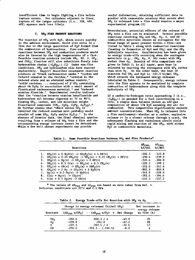
Nevertheless, potential effects of the release ofUFg into a fire can be evaluated. Several possiblereactions involving UFg and CH4, H2, C, and CO--combustible materials chosen as surrogates for thebroad range of gases present within H fire--arelisted in Table 1 along with combustion reactions(leading to formation of H2O and CO2) and the UFghydrolysis reaction. Consideration has been givento energy trade-offs occurring when the surrogatematerials (e.g., CH4, H2, C, CO) react with UFgrather than O2. Results of this comparison aregiven in Table 2; in all cases, more heat isreleased by reacting the surrogates with UFg ratherthan with O2. On the other hand, the heat ofreaction for UFg and H2O is -101.5 kj/mol UFg,which exceeds the increased energy releasestabulated in Table 2. Consequently, energy releaseinto the fire appears to be maximized by completecombustion of hydrocarbons along with the completehydrolysis of UFg.
If a carbon-to-hydrogen ratio approaching 2 (i.e.,-CnH2n-) is assumed for a fuel contributing to afire, a simple mass balance yields an off-gascomposition of about 13% H2O assuming dry air forcombustion. This composition significantly exceedsambient concentrations. When UFg is released into2 fire environment--whether as a .sudden, explosiverelease or in a slower release through a crack, thesubsequent flashing and turbulence should yieldrapid mixing and reaction of the UFg, with eitherH2O or combustible materials.
Table 1. Soae Possible Reactions between UFg and Fire Products8
ReactionsAHr AG'rxn<kJ/mol kJ/mol
1. UFg(v) + 2 H>>0(v) -> UO2F2(s) + 4 HF(v)2. UFg(v) + 0.25 CH4(v) -> UF4(s) + 0.25 CF4(v) + HF(v)3. UFg(v) + H2(v) -> UF4(s) + 2 HF(v)4. UFg(v) + 0.5 C(s) -> UF4(s) + 0.5 CF4CV)5. UF6(v) + C0(v) -> UF4(s) + COF2(v)6. CH4(v) + 2 O2 -> C02(v) + 2 H20(v)7. H2(v) +0.5 02(v) -> H20(v)8. C(s) + 02(v) -> C02(v)9. C(s) + 0.5 02(v) -> C0(v)
a The values of AH r x n and AG r x n are based on data taken from Ref. 4.Reference conditions are 25"C and 0.1 MPa
-101.5-250.4-309.4-229.3-291.0-802.3-241.8-393.5-110.5
-123.8-239.9-306.0-199.1-241.6-800.8-228.6-394.4-137.2
Table 2. Energy Trade-offs for Reaction with UFg vs O2
Change in energy released (kJ/mol UFg)
Reactant (AHrXn w/UFg) (AHrxn w/02)
Net increase inenergy release
Net Change to fire (%)
CH4H 2cCO
-250.4-309.0-229.3-291.0
-802, .3-241
-393.393.5 •
.5
/ *.8
/ 2(-110. 5)
-49.8-67.2-32.6-8.0
2528173
18
II. CYLINDER RUPTURE DOE TO FIRK
The tine required to rupture a cylinder exposed tofire has been conservatively estimated. Resultsare compared to experiments conducted in 1965.
FIRE CONDITIONS
There are several sources of fire conditions whichmay be used for analysis of fire effects. NRCcriteria are as follows:(5)
Exposure of the whole specimen for notless than 30 minutes to a heat flux notless than that of a radiation environmentof 800*C (1475*F) with an emissivitycoefficient of at least 0.9. Forpurposes of calculation, the surfaceabsorptivity must be either that valuewhich the package may be expected topossess if exposed to a fire or 0.8,whichever is greater.
Buck and Belason included the following descriptionof a design fire environment relative to a proposedASTM standard:(6)
A total heat flux of 174 kW/m2
(15.28 Btu/ft2s) *;ith components of158 kW/m2 (13.89 Btu/ft2«s) radiativeheat flux and 16 kW/m2 (1.39 Btu/ft2-s)convective heat flux, average flametemperatures of between 983'C (1700*F)and 1261'C (2300"F) ...
They also argue that "in ... large hydrocarbon poolfires, it [is] reasonable to assume an emissivityof 1.0" since "the flanes only have to be 3 to 6feet thick to be optically opaque."
The tabulated results presented subsequently assumea flame temperature of 1475*F and a flameemissivity of 1.0. It is also assumed (for thecase of complete immersion in a fire) that theconvective heat flux to the cylinder, which wouldbe about 10% of the total heat flux based on theproposed ASTM standard, is negligible relative toother uncertainties.
CYLINDER RUPTURE CONDITIONS
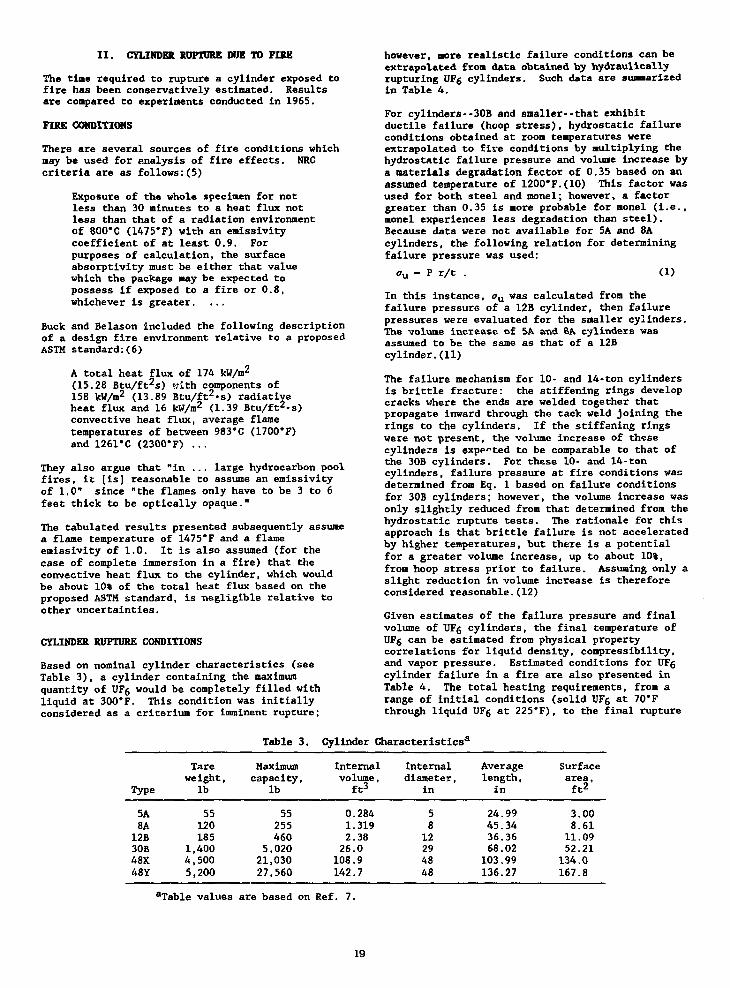
Based on nominal cylinder characteristics (seeTable 3), a cylinder containing the maximumquantity of UFg would be completely filled withliquid at 300*F. This condition was initiallyconsidered as a criterlum for imminent rupture;
however, more realistic failure conditions can beextrapolated from data obtained by hydraulicallyrupturing UFg cylinders. Such data are sunnarizedin Table 4.
For cylinders--30B and snaller--that exhibitductile failure (hoop stress}, hydrostatic failureconditions obtained at room temperatures wereextrapolated to fire conditions by multiplying thehydrostatic failure pressure and volume increase bya materials degradation factor of 0.35 based on anassumed temperature of 1200*F.(10) This factor wasused for both steel and monel; however, a factorgreater than 0.35 is more probable for monel (i.e.,monel experiences less degradation than steel).Because data were not available for 5A and 8Acylinders, the following relation for determiningfailure pressure was used:
<7U - P r/t . (1)
In this instance, an was calculated from thefailure pressure of a 12B cylinder, then failurepressures were evaluated for the smaller cylinders.The volume increase of 5A and 8A cylinders wasassumed to be the same as that of a 12Bcylinder.(11)
The failure mechanism for 10- and 14-ton cylindersis brittle fracture: the stiffening rings developcracks where the ends are welded together thatpropagate inward through the tack weld joining therings to the cylinders. If the stiffening ringswere not present, the volume increase of thesecylinders is expected to be comparable to that ofthe 30B cylinders. For these 10- and 14-toncylinders, failure pressure at fire conditions wasdetermined from Eq. 1 based on failure conditionsfor 30B cylinders; however, the volume increase wasonly slightly reduced from that determined from thehydrostatic rupture tests. The rationale for thisapproach is that brittle failure is not acceleratedby higher temperatures, but there is a potentialfor a greater volume increase, up to about 10%,from hoop stress prior to failure. Assuming only aslight reduction in volume increase is thereforeconsidered reasonable.(12)
Given estimates of the failure pressure and finalvolume of UFg cylinders, the final temperature ofUFg can be estimated from physical propertycorrelations for liquid density, compressibility,and vapor pressure. Estimated conditions for UFgcylinder failure in a fire are also presented inTable 4. The total heating requirements, from arange of initial conditions (solid UFg at 70*Fthrough liquid UFg at 225*F), to the final rupture
Table 3. Cylinder Characteristics8
Type
Tareweight,
lb
Maximumcapacity,
lb
Internalvolume,
ft*
Internaldiameter,
in
Averagelength,in
Surfacearea,ft2
5A8A12B30B48X48Y
145
55120185,400,500,200
55255460
5,02021,03027,560
0.2841.3192.3826.0108.9142.7
5812294848
24.9945.3436.3668.02103.99136.27
3.008.6111.0952.21134.0167.8
aTable values are based on Ref. 7.
19
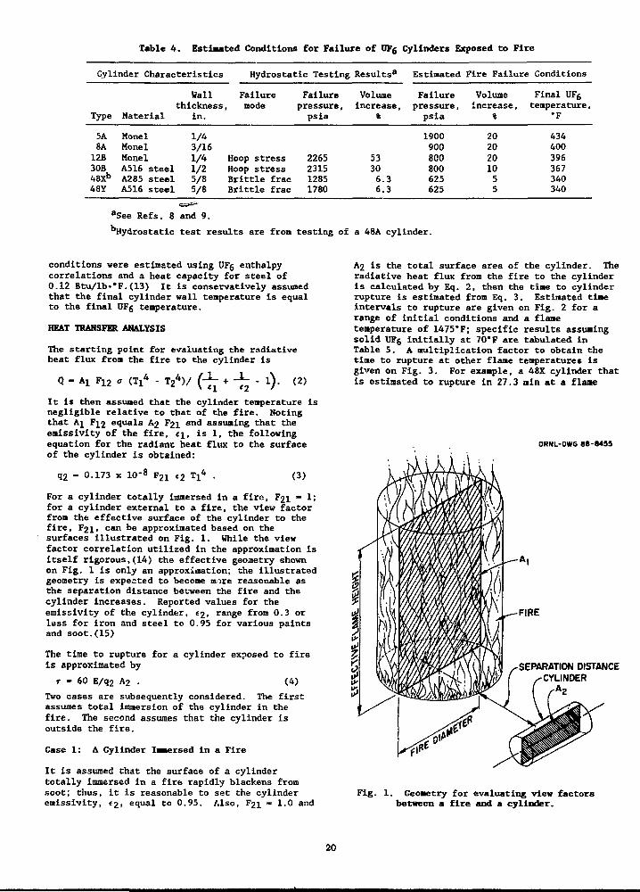
Table 4. Estimated Conditions for Failure of UFg Cylinders Exposed to Fire
Cylinder Characteristics
Type
5A8A12B30B48Xb
48Y
Wallthickness
Material
MonelMonelMonelA516 steelA285 steelAS16 steel
in.
1/43/161/41/25/85/8
Hydrostatic Testing
Failure, mode
Hoop stressHoop stressBrittle fracBrittle frac
Failurepressure,psia
2265231512851780
Results8
Volumeincrease,
%
53306.36.3
Estimated
Failurepressure,psia
1900900800800625625
Fire Failure
Volumeincrease,
%
2020201055
Conditions
Final UFgtemperature,
•F
434400396367340340
aSee Refs. 8 and 9.bHydrostatic test results are from testing of a 48A cylinder.
conditions were estimated using UFg enthalpycorrelations and a heat capacity for steel of0.12 Btu/lb-*F.(13) It is conservatively assumedthat the final cylinder wall temperature is equalto the final UFg temperature.
HEAT TRANSFER ANALYSIS
The starting point for evaluating the radiativeheat flux from the fire to the cylinder is
Q - AX F12 o - T 24 ) /
<2 • ' ) •
(2)
It is then assumed that the cylinder temperature isnegligible relative to that of the fire. Notingthat Ai F12 equals A2 F2j and assuming that theemissivity of the fire, t\, is 1, the followingequation for the radiant heat flux to the surfaceof the cylinder is obtained:
q2 - 0.173 x 10'8 F21 €2 Tj
4(3)
For a cylinder totally immersed in a fire, F2i - 1;for a cylinder external to a fire, the view factorfrom the effective surface of the cylinder to thefire, F21, can be approximated based on thesurfaces illustrated on Fig. 1. While the viewfactor correlation utilized in the approximation isitself rigorous,(14) the effective geometry shownon Fig. 1 is only an approximation; the illustratedgeometry is expected to become more reasonable asthe separation distance between the fire and thecylinder increases. Reported values for theemissivity of the cylinder, e2, range from 0.3 orless for iron and steel to 0.95 for various paintsand soot.(15)
The time to rupture for a cylinder exposed to fireis approximated by
r - 60 E/q2 A2 (4)
Two cases are subsequently considered. The firstassumes total immersion of the cylinder in thefire. The second assumes that the cylinder isoutside the fire.
Case 1: A Cylinder Iaersed in a Fire
It is assumed that the surface of a cylindertotally immersed in a fire rapidly blackens fromsoot; thus, it is reasonable to set the cylinderemissivity, «2, equal to 0.95. Also, F2i - 1.0 and
A2 is the total surface area of the cylinder. Theradiative heat flux from the fire to the cylinderis calculated by Eq. 2, then the time to cylinderrupture is estimated from Eq. 3. Estimated timeintervals to rupture are given on Fig. 2 for arange of initial conditions and a flametemperature of 1475*F; specific results assumingsolid UFg initially at 70*F are tabulated inTable 5. A multiplication factor to obtain thetime to rupture at other flame temperatures isgiven on Fig. 3. For example, a 48X cylinder thatis estimated to rupture in 27.3 min at a flame
ORNL-DWG 8B-8455
SEPARATION DISTANCECYLINDER
Fig. 1. Geometry for evaluating view factorsbetween a fire and a cylinder.
20

26
24
22
20-
10 -
1 0 -
14 -
12-
10-
0 -
0 -
4 -
2 -
0 -
40Y -^_401 - < ^ ^ _ ^
SOB — ^ ^ _ _ _ _ ^
" -
e» -—54 _
OKNL-DWC 0KC-MS2
- — —
— SOB
• 12B5*
CUmL-Df G WC-M53
110 130 150 170 1 »
INITIAL CYUHJEJl TEMFDUTUltE, T
Fig 2. Estimated ti>e interval to cylinder rupturebased on a flue temperature of 1475*F.
1.000 1.000 2.000
F1AHE TEMPER1TUM, T
Fig. 3. Multiplication factor for adjustingthe results given in Fig. 2 to temperatures
other than 1475*F.
teaperature of 1475*F would rupture at 12.3 Binbased on a 1900*F flame which yields amultiplication factor of 0.45.
Case 2: A Cylinder Adjacent to a Fire
For this second case, fires of several sizes wereconsidered. Fire diameters at the ground surfaceof 10, 20, and 50 ft were selected,, and effectiveflame heights twice the fire diameter were assumedbased on the work of Mudan.(16) [Greater height todiameter ratios could have been assumed; but, sincethe fire is approximated as a right-circularcylinder (see Fig. 1) rather c'.--m as a cone, aratio of 2 was considered a compromise.] Figure 4summarizes view factors, F21, from the cylinder tothe fire; the view factors are not a strongfunction of cylinder size when separation distancesexceed about 10 ft. A surface area multiplier,which is the ratio of the effective surface area(length x diameter) to the total surface area (seeTable 4), is given in Table 6. For a cylinder
Table 5. Estimated Time Intervalto Cylinder Rupture
UFg phase SolidCylinder temperature 70*FFlame temperature 1475*F
Heat flux 23,000 Btu/hr»f
Cylindertype
5A8A
12B30B48X48Y
Total heatrequirements,
Btu
6,40021,90038,000
364,0001,400,0001,810,000
Time torupture,
Bin
5.76.89 .1
18.527.328.2
adjacent to a fire, its emissivity, C2< c a n rangefrom less than 0.3 up to 0.95, depending on thesurface finish, as noted earlier.
To estimate the time to rupture for a cylinderadjacent to a fire multiply the time to rupture fora cylinder immersed in a fire (Fig. 2 or Table 5)by the flame temperature multiplication factor(Fig. 3) and the surface area multiplier (Table 6)and divide by the view factor (Fig. 4). If anemissivity other than 0.95 is assumed for thecylinder, multiply the result by 0.95 and divide bythe assumed emissivity. For example, a 12Bcylinder initially at 70*F will rupture in about1 h when exposed to a 20-ft diam, 1900*F fire at adistance of 10 ft (i.e., 9.1 x 0.45 x 3.66 + 0.24 -62 min) . Table 7 indicates time interval rangesneeded to reach rupture conditions for a range offire conditions.
RELATED STUDIES
In October 1965, cylinders containing from 5 to250 lb of UFg were exposed to fire in a series oftests conducted at the Oak Ridge Gaseous DiffusionPlant (ORGDP).(17) These tests were conducted "todetermine if the cylinders would hydrostatically orexplosively rupture [and] the time available forfire fighting before either incident occurred."The cylinders were mounted where they would becompletely within the fire. A summary of the testsis given in Table 8. During Test V, the cylinderwall temperature approached about 1000*F and UF5temperatures within the cylinder varied between 330and 440'F at the instant the cylinder explosivelyruptured. Mailett concluded that the tests"confirmed that [an] UFg cylinder rupture ofexplosive force is possible and that it can occurwithin a time sufficiently short as to possiblypreclude fire fighting unless initiated verypromptly. The explosions noted cannot beconsidered any more severe or hazardous than thosedue to other chemical or gas explosions. Theamount of water blown from the tank by the force of
21

ORNL-DWC BBC-S4M Table 6. Surface AreaMultipliers for Case 2
SEPASATION DISTANCE, [I
Fig. 4. View factors as a function of separationdistance between fire and cylinder and fire size,
the explosion contributed largely to the fireballformation, a cause which, in most transportationaccidents, is unlikely to be so available." Valvefailures precluded explosions in Test I and IV.
Duret and Bonnard described the results ofexperimental and modeling efforts which includedconsideration of internal heat transfer in an UFgcylinder exposed Co fire.(18) In a directcomparison with Mallett's results (which would beTests III and V), they estimated a time to cylinderrupture of 8 min 40 s assuming a fire temperatureof 800°C (1472°F); rupture would occur at an UFgtemperature of 16CC (320°F). In their analysis,the cylinder wall temperature approached 600°C(1112-F) at the end of 6 min. Predicted failuredurations for 30B and 48Y cylinders exposed to800°C and 900°C fires were also presented (seeTable 9).
UNCERTAINTIES IN THE ANALYSES
Direct comparison of time estimates to cylinderrupture based on the approach described herein (seeTable 5) to the results of the ORGDP tests (seeTable 8) shows a conservative estimate of thattime. Estimated times were 5.7 and 6.8 min for 5Aand 8A cylinders, respectively, assuming a firetemperature of 1475°F, while Mallett's dataindicated actual rupture occurred at 8 min for a5A-sized cylinder and at 8.5 and 10.5 min for two8A-sized cylinders. A number of conservativeassumptions were made in these analyses; anonconservative assumption is offset by theconservative assumptions. The various assumptionsand their impacts--both in general, as well as onthe comparison between calculations andexperiment--are discussed in the followingparagraphs.
Cylinder wall temperature. It has been assumed forthese analyses that the cylinder wall temperaturewill have a negligible impact on the heat flux.However, Mallett's data, as well as the modeling ofDuret and Bonnard, indicate that wall temperatures
Cylindertype
5A8A12B30B48X48Y
Multiplier
3.463.423.663.813.873.69
Table 7. Range of Time Intervals to Rupturefor a Cylinder Adjacent to a Fire, aina
Cylinctype
Fire
Separation
ler! 10
temperature:Cylinder emissivitv:
5A8A12B30B48X48Y
Fire
16 - 5716 - 6923 - 9844 - *62 - *62 - *
temperature:Cylinder emissivitv:
5A8A12B30B48X48Y
Fire
34 - *36 - *51 - *98 - *
**
temperature:Cylinder emissivitv:
5A8A12B30B48X48Y
Fire
49 - *52 - *73 - *
***
temperature:Cylinder emissivitv:
5A8A12B30B48X48Y
108 - *114 - *
****
1900°F0.95
202130588382
1475°F0.95
454767
1900'F0.30
646795
1475°F0.30
distance
20
-----
--***
-
***
*****
i
116*****
***
***
(ft)
31324689
6771101
97102
40
---**
--***
*
**
******
****
***
**
aThe first number in each range correspondsto an initial condition of liquid UFg at the triplepoint (147.3°F) exposed to a 50-ft diameter fire;the second number corresponds to solid UFg at 70°Fand a 10 ft fire. An asterisk, *, indicates a timegreater than 2 h.
22
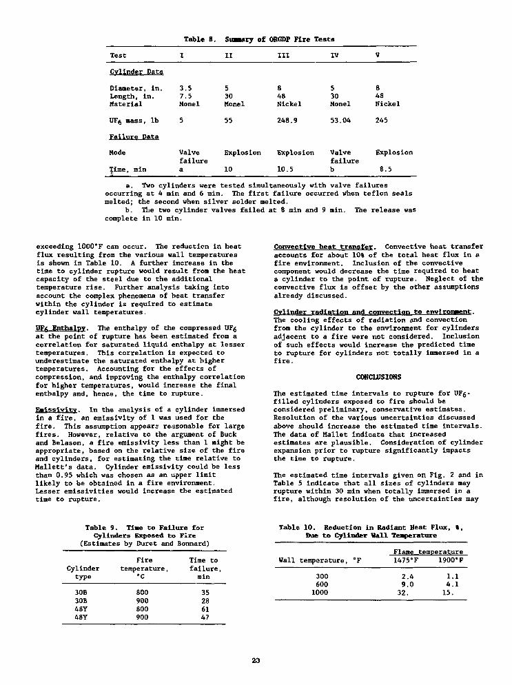
Table 8. Suaaary of ORGDF Fire Tests
Test
Cylinder Data
Diameter, in.Length, in.Material
UFg mass, lb
Failure Data
Mode
Time, minTt
I
3.57.5Monel
5
Valvefailurea
II
530Honel
55
Explosion
10
III
848Nickel
248.9
Explosion
10.5
IV
530Monel
53.04
Valvefailureb
V
848Nickel
245
Explosion
8.5
a. Two cylinders were tested simultaneously with valve failuresoccurring at 4 min and 6 min. The first failure occurred when teflon sealsmelted; the second when silver solder melted.
b. The two cylinder valves failed at 8 min and 9 min. The release wascomplete in 10 min.
exceeding 1000*F can occur. The reduction in heatflux resulting from the various wall temperaturesis shown in Table 10. A further increase in thetime to cylinder rupture would result from the heatcapacity of the steel due to the additionaltemperature rise. Further analysis taking intoaccount the complex phenomena of heat transferwithin the cylinder is required to estimatecylinder wall temperatures.
UFfr Enthalpy. The enthalpy of the compressed UFgat the point of rupture has been estimated from acorrelation for saturated liquid enthalpy at lessertemperatures. This correlation is expected tounderestimate the saturated enthalpy at highertemperatures. Accounting for the effects ofcompression, and improving the enthalpy correlationfor higher temperatures, would increase the finalenthalpy and, hence, the tine to rupture.
Ealsslvitv. In the analysis of a cylinder immersedin a fire, an emissivity of 1 was used for thefire. This assumption appears reasonable for largefires. However, relative to the argument of Buckand Belason, a fire emissivity less than 1 might beappropriate, based on the relative size of the fireand cylinders, for estimating the time relative toMallett's data. Cylinder emissivity could be lessthan 0.95 which was chosen as an upper limitlikely to be obtained in a fire environment.Lesser emissivities would increase the estimatedtime to rupture.
Convectlve heat transfer. Convective heat transferaccounts for about 10% of the total heat flux in afire environment. Inclusion of the convectivecomponent would decrease the time required to heata cylinder to the point of rupture. Neglect of theconvective flux is offset by the other assumptionsalready discussed.
Cylinder radiation and convection to eiwrlroi»ent.The cooling effects of radiation and convectionfrom the cylinder to the environment for cylindersadjacent to a fire were not considered. Inclusionof such effects would increase the predicted timeto rupture for cylinders not totally immersed in afire.
CONCLUSIONS
The estimated time intervals to rupture for VF&-filled cylinders exposed to fire should beconsidered preliminary, conservative estimates.Resolution of the various uncertainties discussedabove should increase the estimated time intervals.The data of Mallet indicate that increasedestimates are plausible. Consideration of cylinderexpansion prior to rupture significantly impactsthe time to rupture.
The estimated time intervals given on Fig. 2 and inTable 5 indicate that all sizes of cylinders mayrupture within 30 min when totally immersed in afire, although resolution of the uncertainties may
Table 9. Tiae to Failure forCylinders Exposed to Fire
(Estimates by Duret and Bonnard)
Cylindertype
30B30B48Y48Y
Firetemperature,
•c
800900800900
Time tofailure,min
35286147
Table
Wall
10. Reduction in Radiant Heat Flux,Due to Cylinder Wall Temperature
temperature, °F
3006001000
t.
Fiamf? temperature
1475°F
2.49.0
32.
1900*F
1.4.15.
.1
.1
23
increase time estimates for the 48X and 48Ycylinders beyond 30 min. For cylinders adjacent tofires, rupture of large cylinders appears much lesslikely. Te&t results show that valve failure mayoccasionally preclude cylinder rupture.
When a cylinder fails in a fire, the release of UF6into the fire will add energy to the fire.
REFERENCES
1. Barber, E. J., Oak Ridge Gaseous DiffusionPlant, Oak Ridge, Tennessee, personalcommunication, December 18, 1985.
2. Rapp, Karl E., "The Pattern of ExplosiveReaction Between Uranium Hexafluoride andHydrocarbon Oils," K/GD-1631, Rev. 1, OakRidge Gaseous Diffusion Plant, Oak Ridge,Tennessee, March 21, 1986.
3. Barber, E. J., personal communication,January 23, 1987.
4. J. Phvs. Chem. Ref. Data.. Vol. 11, Supple. 2,1982.
5. 10 CFR Part 71.73(c)(3), August 24, 1983.
6. Buck, Michael E., and Belnson, E. Bruce, "ASTMTest for Effects of Large Hydrocarbon PoolFires on Structural Members," Plant/OperationsProgress. Vol. 4. No. 4, pp. 225-229, October1985.
7. "Uranium Hexafluoride: Handling Proceduresand Container Criteria," ORO-651, Rev. 4, OakRidge Operations Office, U.S. Energy Researchand Development Administration, Oak Ridge,Tennessee, p. 73, April 1977.
8. Barlow, C. R., Oak Ridge Gaseous DiffusionPlant, Oak Ridge, Tennessee, personalcommunication, March 29, 1988.
9. Barlow, C. R., Ziehlke, K. T., andPryor, W. A. , "Effects of Fire Exposure onIntegrity of UF6 Shipping Cylinders," K-2056,Martin Marietta Energy Systems, Inc., OakRidge, Tennessee, June 17, 1985.
10.
11.
12.
13.
14.
"Military Standardization Handbook: MetallicMaterials and Elements for Aerospace VehicleStructures," MIL-HDBK-5C, Department ofDefense, Washington, D.C., p. 2-18,September 15, 1976.
Hammond, C. R., Martin Marietta EnergySystems, Inc., Oak Ridge, Tennessee, personalcommunication, March 29, 1988.
Theiss, T. J., Martin Marietta Energy Systems,Inc., personal communication, March 30, 1988.
Perry, Robert H., and Chilton, Cecil H.,Chemical Engineers' Handbook. 5th edition,McGraw-Hill Book Company, New York, p. 3-136,1973.
Hsu, Chai-Jung, "Shape Factor Equations forRadiant Heat Transfer between Two ArbitrarySizes of Rectangular Planes," The CanadianJournal of Chemical Engineering. Vol. 45,pp. 58-60, February 1967.
15. Siegel, Robert, and Howell, John R., ThermalRadiation Heat Transfer. 2nd ed., HemispherePublishing Corporation, Washington, D.C.,pp. 832-5, 1981.
16. Mudan, Krishna S., "Hydrocarbon Pool and VaporFire Data Analysis," DOE/EP/16008-1,A. D. Little, Inc., Cambridge, Massachusetts,p. 100, October 1984.
17. Mallett, A. J., "ORGDP Container Test andDevelopment Program: Fire Tests of UF5-FilledCylinders," K-D-1894, Oak Ridge GaseousDiffusion Plant, Oak Ridge, Tennessee,January 12, 1966.
18. Duret, B. and Bonnard, J. C., "Behavior of UFgPackage in Fire--Comparison of Calculationswith Fire Experiment," PATRAM '83Proceedings. Seventh International Symposiumon Packaging and Transportation of RadioactiveMaterials, New Orleans, Louisiana, May 15-20,1983, CONF-830528-Vol. 1, Oak Ridge NationalLaboratory, Oak Ridge, Tennessee, pp. 747-754,December 1983.
24
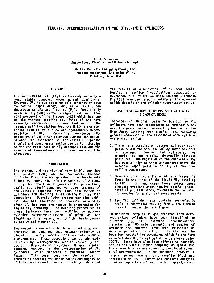
FLUORINE OVERPRESSURIZATION IN VHE (FIVE-INCH) CYLINDERS
A. J. SaracenoSupervisor, Chemical and Materials Dept.
Martin Marietta Energy Systems, Inc.Portsmouth Gaseous Diffusion Plant
Piketon, Ohio USA
ABSTRACT
Uranium hexafluoride (UF,) is thermodynamicaiiy avery stable compound under normal conditions.However, UF( is subjected to self-irradiation (dueto natural alpha decay) and, as a result, candecompose to UFx and fluorine (F 2). Very highlyenriched UF6 (VHE) contains significant quantities(1-2 percent) of the isotope U-234 which has oneof the highest specific activities of the morecommonly encountered uranium isotopes. Theintense self-irradiation from the U-234 alpha par-ticles results in a slow and spontaneous decom-position of UF6. Operating experience withcylinders of VHE after extended storage has demon-strated the existence of non-volatile deposits(heels) and overpressurization due to F2. Studieson the estimated rate of UF, decomposition and theresults of examinations of cylinder heels will bediscussed.
INTRODUCTION
The storage and transfer of very highly enrichedtop product (VHE) at the Portsmouth GaseousDiffusion Plant are accomplished in nuclearly safe5-inch cylinders with minimum spacing of 2-feet.During the more than 30 years of VHE production,small, but significant and variable, amounts ofnon-volatile deposits have been encountered incylinders and sampling lines during VHE transferoperations. Deposit-laden systems may also exhi-bit abnormal elevation of pressure especiallyafter UFS has been pre-heated in preparation forliquid UF, sampling. The handling procedures inthese instances have been modified to addresscylinder overpressurization, plugging of theliquid sampling system, and cylinder heels causedby non-volatile material.
The recent increased emphasis on uranium accoun-tability has demanded that greater priority beplaced on quality sampling and accurate uraniummeasurements. These operations can be adverselyaffected by heterogeneous samples caused by de-posits in UF,-containing systems. Of even greaterconcern, however, is the overpressuring of UF,cylinders, which presents a potential safetyissue. This paper describes the results ofstudies to identify the basic causes and magnitudeof this overpressurization of 5-inch cylinders and
the results of examinations of cylinder heels.Results of earlier investigations conducted byBernhardt et al at the Oak Ridge Gaseous DiffusionPlant(l) have been used to interpret the observedsolids deposition and cylinder overpressurization.
BASIC OBSERVATIONS OF OVERPRESSURIZATION IN5-INCH CYLINDERS
Instances of abnormal pressure buildup in VHEcylinders have been encountered at numerous timesover the years during pre-sampling heating at theHigh Assay Sampling Area (HASA). The followinggeneral observations are associated with cylinderoverpressurization:
1. There is a correlation between cylinder over-pressure and the time the VHE cylinder has beenin storage. Newly-filled cylinders, forexample, do not display abnormally elevatedpressures. The magnitude of the overpressuringhas been as high as three atmospheres above theexpected vapor pressure of UF, at the pre-vailing temperature.
2. Deposits of non-volatile solids are frequentlyfound in the lines of the liquid UFS samplingsystems. In many cases these solids causeplugging problems which require special proce-dures (e.g., filtration) to obtain the requiredUF6 samples for analytical measurements.
3. The VHE cylinders may contain non-volatileheels in quantities varying from a few hundredgrams to greater than a kilogram.
In addition, samples of gas obtained from over-pressurized cylinders have been identified asfluorine (F2) in substantial concentrations(greater than 80 mole percent), and samples ofcylinder heel material have been identified asuranium pentafluoride (UF;,). The UFS has thebeta-form crystalline structure, which is the formexpected when UF, is reduced at temperatures below300°F. There have also been efforts to identifythe solids within liquid sampling equipment buttheir amorphous nature generally precluded struc-tural determination. In one instance, however, asample removed from a liquid sampling block wasidentified as UF5. Direct wet chemical analysisof other deposits confirmed the high uranium con-
25
tent. It is likely that these materials are alsoUFS as in the case of the cylinder heels.
Of the number of possible causes of the aboveobservations, the decomposition of UF, due toself-irradiation is considered the most likelyexplanation of both the overpressurization andheel formation encountered with VHE cylinders. Adetailed look into a mechanism, which has beenlargely disregarded in UF, handling operations, isprovided below.
DECOMPOSITION DUE TO ALPHA IRRADIATION
Past studies on the alpha irradiation of UF,,using radon as the alpha source, form the basis ofmuch of the discussion presented here(l). Theresults of these studies applied to VHE productcharacteristics, present a convincing case thatself-irradiation of UF, by alpha particles resultsin its dissociation and formation of UFX and Fz.The extent of this decomposition is largely depen-dent on the U-234 content and time. UF, at VHEassays contains significant levels of U-234, whichhas a considerably highe- specific alpha activitythan U-235, U-236 or U-238 (Table 1).
TABLE 1 SPECIFIC ACTIVITIES OF U-ISOTOPES(disintegrations/sec/gram)
U-234 1.54 x 10jU-235 5.34 x 10U-236 1.58 x 10!U-238 8.34 x 10
When an alpha particle, strikes a UF, molecule,approximately 1.37 x 10 ion pairs are formed overits path length. (This figure is based on a gasphase determination and is assumed to also be theapproximate value for the solid phase.) VHE pro-duct decomposition occurs as a result of self-irradiation by alpha particles according to thefollowing equation:
UF alpha6 radiation
UFv F2; x
Although theoretically the solid UFX compound mayhave any stoichiometry intermediate between UF,and several subfluorides (UFS, UF,,, etc), onlybeta uranium pentafluoride has been identified asthe primary solid uranium fluoride in cylinderheels. The fluorine produced by this reactionwould be expected to build up slowly in a sealedcontainer at a rate determined by several factors.It might be expected that over a sufficiently longperiod of time, all the UF, would be eventuallyreduced to solid UFX. However, a reverse reac-tion, also induced by alpha particles, can opposethe decomposition as follows:
{-TI-^ Fs + UFv + 7"=-'- : • UFcv 2 ' 2 x radiation 6
The fluorination of UFX compounds with fluorinenormally occurs at a significant rate only at hightemperatures. UF4, for example, is not rapidlyconverted to UF6 by F2 until temperatures above400°F are present(2). However, UFX deposits(previously formed by radon alpha decomposition ofUF6) can be converted at measurable rates back toUF, in the presence of F2 at room temperatureunder the influence of alpha radiation(l). Under
self-irradiation exposure, the decomposition ofVHE UF, (in a sealed system where the Fz cannotescape) would be expected to reach an equilibriumat which point the UFX deposit formation rateequals the conversion rate back to gaseous UF,.The rate of the reverse reaction is a function ofthe available surface area of the UFX deposit aswell as the F, activity for a given radiationenvironment.
DISCUSSION
Calculations were made to estimate the quantity offluorine and UF5 produced based on this decomposi-tion model. The method employed to estimate anupper bound for the degree of alpha-induced decom-position assumed (1) no reverse reaction, (2) nocontainer wall effects, (3) every ion pair formedleads to the decomposition of one UF, molecule.The specific activity and the nominal value (1.37x 10s) for the number of ion-pairs created peralpha particle were used to calculate the quantityof UF5 and Fj, produced for a given time period.
The specific activity (SA) per gram of VHE UF, ofisotopic composition given in Table 2 was calcu-lated using the equation:
SA = (dps/g)
where: Xf = decay constant of isotope i= 0.693/ti, where tf = half life
in secondsA = number of molecules/
mole = 6.023 x 1 0 "Wi = isotopic weight fractionMi = molecular weight, grams/mole
TABLE 2 ASSUMED ISOTOPIC COMPOSITION OF UF, FORCALCULATION OF DECOMPOSITION RATE
U-234U-235U-236U-238
1.20%97.35%
0.0%1.45%
The results indicate that decomposition of UF6 toUFX and F2, due to self-irradiation, would be onthe order of 0.48% by weight per year. The esti-mated quantity of fluorine generated in one yearfor 25 Kg of UF, (fill limit for VHE cylinders)is 6.5 grams. With a free space of 1 liter, thisquantity of F2 would be expected to produce apressure in excess of 60 psia at room temperature,neglecting the solubility of F-, in solid UF6 andcorrosion losses. The quantity of UFS heel pro-duced is calculated to be 113 grams.
In addition to U-234, the presence of other radio-nuclides of high specific activity, and at suf-ficiently high concentrations, would be expectedto contribute to UF, decomposition. Decompositiondue to the uranium isotopes U-232 and U-236 is notsignificant since the concentration of U-235 hashistorically been below 0.02 weight percent in VHEmaterial, and no U-232 has been detected in VHE atthe analytical limits of sensitivity (2 parts perbillion, U-basis). The only non-uranium radioac-tive contaminant encountered in VHE product thathas the potential for radiation-induced UF,
26

decomposition is technetium-99, which is a weakbeta emitter present in trace amounts in recycleduranium from reactors. While the specific acti-vity of technetium-99 is nearly three times thatof U-234, the energy of its beta particle is con-siderably less than that for the alpha particlesfrom uranium isotopes. Additionally, the con-centrations of Tc-99 in VHE product are typicallyfour to five orders of magnitude below those ofU-234; therefore, no significant effect from thepresence of Tc-99 is expected.
CONCLUSIONS
The calculated pressures of F2 created as a resultof the dissociation of UFt due to self-irradiationcorrelate with pressures actually observed andtherefore supports the model for the production ofcylinder overpressurization and heel formation.The solid in cylinder heels and sampling systemshas been identified as beta UF5, while the gascontributing to the cylinder overpressure is Fa.
This model is also supported by observationsshowing that the amount of F2 overpressure is afunction of storage time. G. B. Binstock of E. I.Dupont (Savannah River Plant) has also observedthat the quantity of VHE cylinder heel variesdirectly with cylinder storage time(3). There isa lack of data, however, on whether the rela-tionship is linear or whether it begins to plateaudue to a reverse (fluorination) reaction. This isconsidered an important unknown aspect of theproblem since it would determine to what extent
the pressure buildup is self limiting and mightprovide approaches to minimizing or managing theproblem more efficiently.
Overpressurization in 5-inch (VHE) cylinders andthe formation of non-volatile heel materialrequires special attention during handling andtransfer of VHE product. In addition to thesafety aspects of the F2 pressure buildup inheated cylinders, there is interest in heel for-mation from the standpoint of improved samplingand uranium accountability. The operationalapproach at Portsmouth has been multi-faceted andinvolves special procedures for handling theoverpressurization and heel problems, while main-taining the storage time as short as possible.
REFERENCES
1. Bernhardt, H. A., Davis, Jr., W., and Shiflett,C. H., "Radiation Effects of Alpha Particles onUranium Hexafluoride," Proceedings of theSecond United Nations International Conferencein the Peaceful Uses of Atomic Energy, Volume29, Chemical Effects of Radiation, UN Publica-tion-P/522, pp. 62-70, 1958.
2. Labaton, V. Y., and Johnson, K. D. B., "TheFluorides of Uranium-III Kinetic Studies of theFluorination of Uranium Tetrafluoride byFluorine," Journal of Inorganic and NuclearChemistry, Vol. 10, pp. 74-85, 1959.
3. Binstock, G. B., E. I. Dupont, Savannah River,Private Communication.
Praparad by tha Porttmouih Gataoue OHTution Plant,Plk.lon. Ohio 45661. oparatad by MARTINMARIETTA ENERGY SYSTEMS. INCORPORATED,lor tha U.S. DEPARTMENT Of ENERGY. uKterContiaa No. DEAC05-76OR00001.
Tha submklad manuscript h a &aan author*] by aconiraoor ot tha U.S. Govammanl undar Contract No.OE-AC05-76OR0O001. Accordingly, tha U.S.Govarnmant ralalns a nonaxdulhnt. royaky-fraalicansa to publish or raproduca tna puWWtad form orIhtt contribution, or aSow othan to do so. tor U.S.Govammant Purpotaa.
27
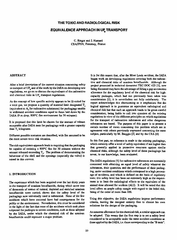
THE TOXIC AND RADIOLOGICAL RISK
EQUIVALENCE APPROACH IN UF, TRANSPORT
C. Ringot and J. HamardCEA/IPSN, Fontenay, France
ABSTRACT
After a brief description of the current situation concerning safetyin transport of UF6 and of the work by the IAEA on developing newregulations, we go on to discuss the equivalence of the radioactiveand chemical risks in UF6 transport regulations.
As the concept of low specific activity appears to be ill-suited fora toxic gas, we propose a quantity of material limit designated T2
(equivalent to Aj for radioactive substances) for packagings unableto withstand accident conditions equal to those laid down by theIAEA (9 m drop, 800°C fire environment for 30 minutes).
It is proposed that this limit be chosen for the amount of releaseacceptable after IAEA tests for packagings with a greater capacitythan T2 kilograms.
Different possible scenarios are described, with fire assumed to bethe most severe toxic risk situation.
The risk equivalence approach leads to requiring that the packagingbe capable of resisting a 800°C fire for 30 minutes without theamount released exceeding T2. The problem of demonstrating thebehaviour of the shell and the openings (especially the valve) israised in this context.
1. INTRODUCTION
The experience which has been acquired over the last thirty yearsin the transport of uranium hexafluoride, during which some tensof thousands of tonnes of natural, depleted and enriched uraniumhexafluoride were carried, shows that the safety level of thepackagings now universally used is substantial. None of the fewaccidents which have occurred have had consequences for thepublic or the environment. Nevertheless, this must be consideredin the light of the fact that none of the accidents which took placesubjected the packages to severe conditions, such as those adoptedby the IAEA, under which the chemical risk of the uraniumhexafluoride could represent a major problem.
It is for this reason that, after the Mont Louis accident, the IAEAbegan work on developing regulations covering both the radioac-tive and chemical risks of uranium hexafluoride. Although theproject presented in technical document TEC-DOC 423 [1], nowbeing discussed may have the advantage of filling a gap as concernsallowance for the regulatory level of the chemical risk for high-capacity packages, which had not previously been taken intoconsideration [2], it is nevertheless not fully satisfactory. Thereport acknowledges this shortcoming as it emphasizes that thelogical approach is to guarantee an equivalent radiological andchemical risk but that such an approach needs to be given carefulconsideration, being liable to call into question all the existingregulations in view of the different principles on which regulationsfor the transport of radioactive substances and other dangeroussubstances are based. The purpose of this paper is to present acertain number of views concerning this problem which are inagreement with others previously expressed concerning the samesubject, particularly by M. Biaggio [3] and by the CEA [4].
In this first part, no reference is made to the existing packagings,which certainly offer a level of safety equivalent if not higher thanthat generally applied in protective mea:'.ires against similarchemical risks, although the safety level of these packagings hasnever, to our knowledge, been evaluated.
The IAEA regulations [S] for radioactive substances are essentiallyconcerned with obtaining an equal level of safety whatever thesubstances, their quantities and the performance of their packag-ing, under accident conditions which correspond to a high percent-age of accidents, and which is defined on the basis of regulatorytests; this safety level has been set extremely high as the require-ment is to limit the radiological effects to the equivalent of theannual dose allowed for workers (ALI). It will be noted that thislevel offers an ample safety margin with regard to the lethal risk,being of the order of more than 100.
Using this objective, the IAEA regulations impose performancecriteria, leaving the designer entirely free to choose his ownsolutions for the design of the packaging.
As concerns allowance for the chemical risk, a similar approach canbe adopted. This means that the first step is to set a safety levelconsidered to be acceptable under the same accident conditions asthose applied by the IAEA, i.e. those corresponding to the "B tests".
29
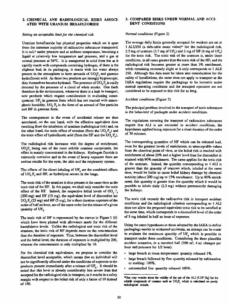
2. CHEMICAL AND RADIOLOGICAL RISKS ASSOCI-ATED WITH URANIUM HEXAFLUORIDE
3. COMPARED RISKS UNDER NORMAL AND ACCI-DENT CONDITIONS
Setting an acceptable limit for the chemical risk.
Uranium hexafluoride has physical properties which set it apartfrom the immense majority of radioactive substances transported.It is soliJ under pressure and at ambient temperature, becoming aliquid at relatively low temperature and pressure, and a gas atnormal pressure at 56°C. It is transported in solid form but as itrapidly reacts with compounds containing hydrogen, if there is theslightest leak in its packaging, it reacts with the water alwayspresent in the atmosphere to form aerosols of UOjF2 and gaseoushydrofluoric acid. As these two products are strongly hygroscopic,they themselves become hydrated. The presence of UO2 F2 is easilydetected by the presence of a cloud of white smoke. One findstherefore in the environment, whenever there is a leak in transport,new products which require consideration in evaluating conse-quences: UF6 in gaseous form which has not reacted with atmos-pheric humidity, UO2 F2 in the form of an aerosol of fine particlesand HF in gaseous form.
The consequences in the event of accidental release are thenassociated, on the one hand, with the effective equivalent doseresulting from the inhalation of uranium (radiological risk) and, onthe other hand, the toxic effect of uranium (from the UO2 F2) andthe toxic effect of hydrofluoric acid (from the HF and the UO2 F2).
The radiological risk increases with the degree of enrichment;UO2F2 being one of the most soluble uranium compounds, theeffect is mainly concentrated in the kidneys. Hydrogen fluoride isextremely corrosive and in the event of heavy exposure there areserious results for the eyes, the skin and the respiratory system.
The effects of the direct inhaling of UF6 are the combined effectsof UO2 F2 and HF, as hydrolysis occurs in the lungs.
The toxic risk of the uranium is thus present at the same time as thetoxic risk of the HF. In this paper, we shall only consider the toxiceffect of the HF. Indeed, the respective lethal levels of UO2 ?2
(200 mg) and HF (IS mg), the equivalent level of discomfort ibrUO2 F2 (25 mg) and HF (5 mg), for a short duration exposure of theorder of half an hour, are of the same order for the release of a givenquantity of UF6.
The toxic risk of HF is represented by the curves in Figure 1 [6]which have been plotted with allowance made for the differentharmfulness levels. Unlike the radiological and toxic risk of theuranium, the toxic risk of HF depends more on the concentrationthan the duration of exposure. Thus, between the discomfort leveland the lethal level, the duration of exposure is multiplied by 200,whereas the concentration is only multiplied by 10.
For the chemical risk equivalence, we propose to consider thediscomfort level acceptable, which means that an individual willnot be significantly affected under the conditions of exposure to theproducts present immediately after a release of UF6. It should benoted that this level is already considerably less severe than thataccepted for the radiological risk in transport, as it results in a safetymargin with respect to the lethal risk of only a factor of 10 insteadof 100.
Normal conditions (Figure 2)
The average daily limits generally accepted for workers are set at1 ALI/250 (a debatable mean value)* for the radiological risk,2.5 mg of uranium (3.7 mg of UF6) and 2 mg of HF (6 mg of UF6)for the toxic risk. The toxic risk of the uranium is, under theseconditions, in all cases greater than the toxic risk of the HF, and theradiological risk becomes greater at more than 3% enrichment,while remaining extremely slight as it only corresponds to 1 AH/250. Although this data must be taken into consideration for thesafety of installations, the same does not apply to transport as theIAEA regulations require the packagings to be hermetic undernormal operating conditions and the transport operators are notconsidered to be exposed to this risk for as long.
Accident conditions (Figure 3)
The principal problem involved in the transport of toxic substancesis the behaviour of packages under accident conditions.
The regulations covering the transport of radioactive substancesrequire that ALI is not exceeded in accident conditions, thehypotheses applied being exposure for a short duration of the orderof 30 minutes.
The corresponding quantities of HF which can be released lead,even for the greatest levels of enrichment, to unacceptable valuesfrom the chemical point of view, as the lethal risk is reached withenrichment of about 20% and a higher level than for discomfort isattained with 90% enrichment The same applies for the toxic riskof the uranium. Indeed, the quantity corresponding to 1 ALI isgreater than the quantity of uranium which, inhaled at the sametime, would be liable to cause lethal kidney damage by chemicaltoxicity (about 200 mg) up to 15% enrichment. Up to 90% enrich-ment, this quantity is greater than the quantity which it would bepossible to inhale daily (2.3 mg) without permanently damagingthe kidneys.
The toxic risk exceeds the radioactive risk in transport accidentconditions and the radiological criterion corresponding to 1 ALIdoes not allow the proposed equivalent toxic risk to be satisfied atthe same time, which corresponds to a discomfort level of the orderof 5 mg inhaled in half an hour of exposure.
Using the same hypotheses as those adopted by the IAEA to definepackagings unable to withstand accidents, an attempt can be madeto evaluate the maximum quantity of UF6 which is possible totransport under these conditions. Considering the three plausibleaccident scenarios, in a standard hall (300 m3, 4 air changes perhour and presence for 1/2 hour):
• large breach at room temperature: quantity released 1%,
• large breach followed by fire: quantity released by sublimationor melting: 100%,
• uncontrolled fire: quantity released 100%.
*One may wonder about the validity of the use of the ALI (5.10* Bq) for thesoluble compounds of uranium such as UO,Ft which is calculated on purelyradiological criteria.
30

The acceptable quantities are respectively of the order of 10 kg andabout one hundred grammes. The fire case is the most severe,especially as the aerosol concentration rapidly reaches levels atwhich visibility is practically zero, making evacuation extremelydifficult.
The fact that it is forbidden to store packagings of UF6 in halls closeto combustible materials should make it possible to makeallowance only for accident scenarios involving rupture at roomtemperature.
This means that to cover the toxic risk, all packagings containingmore than 10 kg of UF6 must be able to withstand the accidentconditions laid down by the IAEA with an allowable amount ofleakage on completing the tests which can be established on thebasis of the consequences of an accident outside, the occurrence ofan accident of the severity of those provided for in the B tests beingunlikely within a building. This results in an allowable leak rate ofthe order of 6 g/s for HF or 20 g/s for UF6, assuming discharge for30 minutes at ground level under normal conditions, in order not toexceed the discomfort level at a distance of 100 m (Figure 4).
Can the checking of the degree of leaktightness be limited to aduration of half an hour? It is reminded that, for the radiologicalrisk, the IAEA imposes a duration of one week as it assumes thatintervention can last for one week. A duration of intervention of 30minutes is certainly extremely optimistic. Indeed, this assumes thatthe emergency teams would have brought the accident undercontrol within half an hour (which is scarcely credible in the caseof a fire with a duration of half an hour), is that the populationconcerned would have been evacuated within this time. A plau-sible accident scenario is a fire with leakage of the valve initiatedsoon after the start of the fire and continuing for a certain length oftime after the fire has stopped. We estimate at an additional1/2 hour the time necessary to stop the leak by placing a wet clothover the valve. The leakage being slight, the product will tend tosolidify and rapidly form a plug by cooling as it passes through thevalve.
These hypotheses lead to defining an allowable leak in a period ofone hour from the start of the fire; allowable leak rates would thenbe 3 g/s of HF, i.e. 12 g/s of UF6.
4. THE CURRENT REGULATORY SYSTEM: APPLICA-TION OF IAEA REGULATIONS
From the strict application of the IAEA regulations, it appears thatthe problem covering the toxic risk is only present for less than 1%enrichment as once this limit is passed, the packages must meet thecriteria for fissile packages. For UF6 this condition requires thepackagings to remain hermetic after the accident tests, which isstipulated to meet the need to guarantee maintaining controlledmoderation.
At lower than 1% enrichment, the toxic risk is properly preventedwith our hypotheses only for transported quantities of less thanabout 10 kg, as the packagings required do not have to be capableof withstanding accidents.
It will be noticed that the recommendations put forward in theIAEA draft - TEC-DOC 423 currently under discussion, do notcover the toxic risk either, as the recommendations make noreference to design basis accidents, in particular to the case ofpackages of less than 450 litres which are precisely those for whichthe problem of being able to withstand fire is the most crucial.
5. IS THE RADIOLOGICAL RISK OF UF4 CORRECTLYCOVERED BY THE IAEA REGULATIONS?
Allowance for the toxic risk leads to raising in the question, whichmay appear surprising, of the radiological risk and whether it iscovered by the existing regulations at less than 1% enrichment.Indeed, UF6 is considered to be a solid substance of low specificactivity (TEC-DOC 423).
Is UF6 really a solid? §208 of S.S. No. 6 rightly mentions thatallowance should be made for the forming of other dangeroussubstances subsequent to reaction with the atmosphere in the eventof rupture of the containment envelope due to an accident. Indeed,it is the physical state in which the substance is present when thepackaging is faulty which is the one which requires consideration.However, as emphasized in this document, UF6 is then no long asolid, but has become, by dispersion, a gas on breaching of theenvelope which then becomes, at a rate depending on the condi-tions of the accident, an aerosol of UOJFJ and gaseous HF.
Therefore, in our opinion, UF6 should be considered to be a gas forregulatory purposes. It cannot therefore be placed in class LSA I.Can it be placed in class LS AII? Here we come to a delicate matteras the present regulations base the concept of substances of lowspecific activity on the axiom that it is highly improbable for anindividual to inhale more than 10 mg of a substance. This value iscontroversial, even for solids, as there are examples of inhalationof uranium powder by miners which have reached quantities of anumber of hundreds of milligrammes [7], and is difficult to acceptfor gases. This means that the value of A, for a gas cannot beunlimited and that the problem of the value of \ is raised. Theconcept of Aj being equal to 10s ALI is effectively based on thehypotheses that when a packaging of type A is destroyed, onlybetween 1/100 and 1/1000 of its content is in dispersable form, anda fraction between 10* and 103 of this quantity is inhaled.
The authors of system Q [8] considered that this value of 10 mgcould only be exceeded in extreme cases which should not need tobe taken into account. Do not gases, by their physical nature, con-stitute one of these extreme cases?
In the case of UF6, depending on the accident scenarios (rupture atroom temperature with a large or small breach, or rupture under fireconditions), the proportion of UF6 transformed into gaseous UF6 orinto an aerosol of fine particles of UO2 F2 may vary considerably,from values below one thousand to unity. The worst case wouldthen lead to giving A, a value of 10* ALI instead of 10* ALI.Therefore, the maximum quantity of natural UF6 (ALI equal to5.104 Becquerels) which could be transported in a type A packagingwould only be 20 kg instead of the 12 t regularly carried!
31
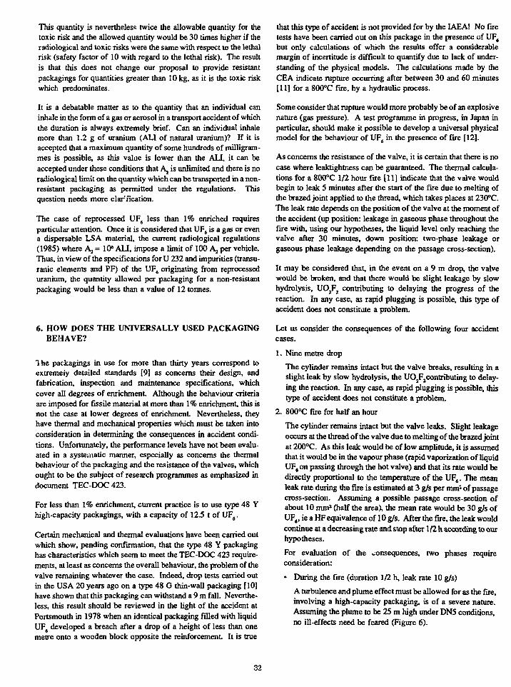
This quantity is nevertheless twice the allowable quantity for thetoxic risk and the allowed quantity would be 30 times higher if theradiological and toxic risks weie the same with respect to the lethalrisk (safety factor of 10 with regard to the lethal risk). The resultis that this does not change our proposal to provide resistantpackagings for quantities greater than 10 kg, as it is the toxic riskwhich predominates.
It is a debatable matter as to the quantity that an individual caninhale in the form of a gas or aerosol in a transport accident of whichthe duration is always extremely brief. Can an individual inhalemore than 1.2 g of uranium (ALI of natural uranium)? If it isaccepted that a maximum quantity of some hundreds of milligram-mes is possible, as this value is lower than the ALI, it can beaccepted under these conditions that A2 is unlimited and there is noradiological limit on the quantity which can be transported in a non-resistant packaging as permitted under the regulations. Thisquestion needs more clar'fication.
The case of reprocessed UF6 less than 1% enriched requiresparticular attention. Once it is considered that UF6 is a gas or evena dispersable LSA material, the current radiological regulations(1985) where A, = 10s ALI, impose a limit of 100 Aj per vehicle.Thus, in view of the specifications for U 232 and impurities (transu-ranic elements and PF) of the UF6 originating from reprocesseduranium, the quantity allowed per packaging for a non-resistantpackaging would be less than a value of 12 tonnes.
6. HOW DOES THE UNIVERSALLY USED PACKAGINGBEHAVE?
Ihe packagings in use for more than thirty years correspond toextremely detailed standards [9] as concerns their design, andfabrication, inspection and maintenance specifications, whichcover all degrees of enrichment. Although the behaviour criteriaare imposed for fissile material at more than 1% enrichment, this isnot the case at lower degrees of enrichment. Nevertheless, theyhave thermal and mechanical properties which must be taken intoconsideration in determining the consequences in accident condi-tions. Unfortunately, the performance levels have not been evalu-ated in a systematic manner, especially as concerns the thermalbehaviour of the packaging and the resistance of the valves, whichought to be the subject of research programmes as emphasized indocument TEC-DOC 423.
For less than 1% enrichment, current practice is to use type 48 Yhigh-capacity packagings, with a capacity of 12.5 t of UF6.
Certain mechanical and thermal evaluations have been carried outwhich show, pending confirmation, that the type 48 Y packaginghas characteristics which seem to meet the TEC-DOC 423 require-ments, at least as concerns the overall behaviour, the problem of thevalve remaining whatever the case. Indeed, drop tests carried outin the USA 20 years ago on a type 48 G thin-wall packaging [10]have shown that this packaging can withstand a 9 m fall. Neverthe-less, this result should be reviewed in the light of the accident atPortsmouth in 1978 when an identical packaging filled with liquidUF6 developed a breach after a drop of a height of less than onemetre onto a wooden block opposite the reinforcement. It is true
that this type of accident is not provided for by the IAEA! No firetests have been carried out on this package in the presence of UF6
but only calculations of which the results offer a considerablemargin of incertitude is difficult to quantify due to lack of under-standing of the physical models. The calculations made by theCEA indicate rupture occurring after between 30 and 60 minutes[11] for a 800°C fire, by a hydraulic process.
Some consider that rupture would more probably be of an explosivenature (gas pressure). A test programme in progress, in Japan inparticular, should make it possible to develop a universal physicalmodel for the behaviour of UF6 in the presence of fire [12].
As concerns the resistance of the valve, it is certain that there is nocase where leaktightness can be guaranteed. The thennal calcula-tions foT a 800°C 1/2 hour fire [11] indicate that the valve wouldbegin to leak 5 minutes after the start of the fire due to melting ofthe brazed joint applied to the thread, which takes places at 230°C.The leak rate depends on the position of the valve at the moment ofthe accident (up position: leakage in gaseous phase throughout thefire with, using our hypotheses, the liquid level only reaching thevalve after 30 minutes, down position: two-phase leakage orgaseous phase leakage depending on the passage cross-section).
It may be considered that, in the event on a 9 m drop, the valvewould be broken, and that there would be slight leakage by slowhydrolysis, UO2F2 contributing to delaying the progress of thereaction. In any case, as rapid plugging is possible, this type ofaccident does not constitute a problem.
Let us consider the consequences of the following four accidentcases.
1. Nine metre drop
The cylinder remains intact but the valve breaks, resulting in aslight leak by slow hydrolysis, the UO2F2contributing to delay-ing the reaction. In any case, as rapid plugging is possible, thistype of accident does not constitute a problem.
2. 800°C fire for half an hour
The cylinder remains intact but the valve leaks. Slight leakageoccurs at the thread of the valve due to melting of the brazed jointat 200°C. As this leak would be of low amplitude, it is assumedthat it would be in the vapour phase (rapid vaporization of liquidUF6 on passing through the hot valve) and that its rate would bedirectly proportional to the temperature of the UF6. The meanleak rate during the fire is estimated at 3 g/s per mm* of passagecross-section. Assuming a possible passage cross-section ofabout 10 mm2 (half the area), the mean rate would be 30 g/s ofUF6, ie a HF equivalence of 10 g/s. After the fire, the leak wouldcontinue at a decreasing rate and stop after 1/2 h according to ourhypotheses.
For evaluation of the consequences, two phases requireconsideration:
• During the fire (duration 1/2 h, leak rate 10 g/s)
A turbulence and plume effect must be allowed for as the fire,involving a high-capacity packaging, is of a severe nature.Assuming the plume to be 25 m high under DN5 conditions,no ill-effects need be feared (Figure 6).
32

• During the half hour following the fire
Release will occur at ground level. As in the preceding phasethe plume effect had protected an area extending out to 500 mfrom the site of the accident, it is considered for the purposesof evaluation of consequences at 100 m that release beginswhen the fire is extinguished. Assuming the same leak rate,ie 10 g/s of HF (which is extremely conservative), for 1/2 h,the consequences are acceptable, being close to the level setfor discomfort (Figure 4).
3. Nine metre drop with breaking of the cylinder followed by an800°C l/2h fire
The UF6, which is solid at atmospheric pressure, will sublimeduring the fire. Dispersion of a large quantity of the substancewill take place during the fire and continue for a number of hoursafter it if action is not taken. Assuming that action is rapidlytaken and that the leak is stopped after one hour, roughly half thecontent will have escaped [14], ie 6 t of UF6, which is equiva-lent to 1.5 t of HF. At a constant leak rate, this represents 2 kgof HF per second. Allowing foT the plume effect, lethal effectswill be observed at distances of 500 to 600 m from the site of theaccident (Figure 7).
4. Uncontrolled fire
Should the cylinder fail to resist an 800cC fire for 1/2 h or shouldthe fire last longer, the cylinder would eventually break andrelease its entire content virtually instantaneously, ie 12.5 t ofUF6 or 4.2 t of HF.
Lethal effects will be observed at distances of 500 to 1000 m(Figure 7).
7. CONCLUSION
The regulations concerning the transport of radioactive substancesprovide a high degree of safety which is equivalent for the toxic andradiological risks in the transport of more than 1% enriched UF6.This is not the case for less than 1% enriched UF6 for which thechemical risk of the.UF6 is the main one. Two approaches thenbecome possible to guarantee an acceptable level of safety. Thefirst approach wouKl be to apply ths same constraints as forchemical products involving a similar type of danger, for examplehydrofluoric acid or chlorine, i.e. to follow the UNO recommenda-tions for class 8. This is the approach which has been adopted indeveloping TEC-DOC 423. The otheT approach would be to applycriteria equivalent to those used for the radiological risk.
It is this second approach which we recommend be developed in thelong term. This approach is consistent with the one used by theIAEA to develop the regulations for the transport of radioactivesubstances, ie of first setting an objective then establishing criteriafor reaching it, indeed appears to be the only one liable to guaranteea known level of safety as it is the one which is self-imposed, whileleaving full scope for innovation as it is criteria which are laid downand not specifications.
REFERENCES
[ 1 ] TEC-DOC 423 AIEA "Recommendations for providing pro-tection during the transport of uranium hexafluoride".
[2] United Nations "Recommendations on the transport of dan-gerous goods" — 4th. revised edition U.N. 1986.
[3] Biaggio et al. "Uranium hexafluoride in transport accident"— Patram 86.
[4] C.T. AIEA 587 — Working paper No. 14 "Quelques scenar-ios en cours de transport terrestre d'un emballage de transportd'UFs naturel — Exemple du 48Y".
[5] S.S. No. 6 AIEA (1985) "Reglementation de transport desmatieres radioactives".
[6] Note technique DAS/SASC No. 87/583 — Sept. 87 "Sub-stances dangereuses presentes dans l'environnement. Inven-taire et evaluation de risque" — par Lhomme.
[7] Health Physics 1987, Koasnicka "Assessing dose equivalentfrom intensive short-term uranium product inhalation".
[ 8] CEGB — TR/B/8340/R83 — Sept. 83 "The Q system for thecalculation of At and Aj value within the IAEA regulations"by Mac Donald and Goldfinch.
[9] American National Standard Institute ANSI 14-1 198
[10] E.W. Richardson 'Testing of fourteen ton uranium hexafluo-ride cylinders" Union Carbide report KY 549 — 15th May1968.
[11] C.T. AIEA 587 —Working paper No. 14 "Comportement encas d'incendie des conteneurs de transport d'UFe".
[ 12] C.T. AIEA 587 — Working paper No. 13 "Japanese research
33

12
13
1 14
II III1E+00
12
13
14
1 1 1 III1E+0I
12
13
1 14
II III1E+02
I2
I3
I4
1 16
18
minutes1E-01
Figure 1
TOXICAL EFFECTS OF ANHTDROUS HF VERSUS CONCENTRATION AND TIME
ENRICHMENT% U235
%
NATUREL
1%
3%
5%
10%
50%
90%
SPEC.ACTIVITY
Bq/9
2.6104
2,8104
5,104
105
1,810s
9,3105
2,210s
EQUIVALENTMASS TOALI/250
mg
8
7
4
2
1.1
0.20
0.09
RADIOLOGICALRISK
TOXICALRISKU
TOXICALRISK HF
UF6 EQUIVALENT MASS TO mg
12
10.5
6
3
1.65
0.30
0.14
3,7
3,7
3,7
3,7
3,7
3,7
3,7
6
6
6
6
6
6
6
Figure 2
ENRICHMENT%U235
%
NATUREL
1%
5%
10%
20%
50%
90%
URANIUM MASSEQUIVALENT TO 1AL1
mg
1,900
1,800
500
300
145
50
20
UF6 MASS
mg
2,800
2,650
750
450
220
75
30
HF MASS
"IP
950
900
250
150
75
23
9
•ALL THE QUANTITY OF FLUOR IS TAKEN IN ACCOUNT (UO2Fj. AND HF)
Figure 3
34
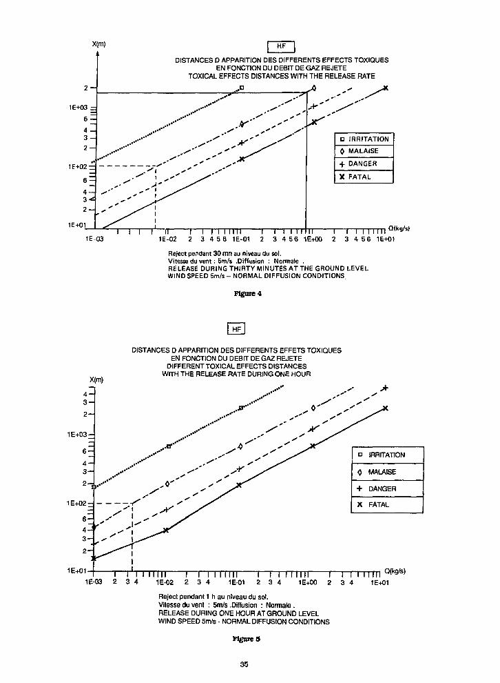
X(m)
2 -
1E+01
DISTANCES D APPARITION DES DIFFERENTS EFFECTS TOXIQUESEN FONCTION DU DEBIT DE GAZ REJETE
TOXICAL EFFECTS DISTANCES WITH THE RELEASE RATE
1E-03I f n
1E-02
\ I I I I I I I I2 3 4 5 6 1E-01
D
0
+X
IRRITATION
MALAISE
DANGER
FATAL
\ i i i 111 ii i r I I i 11112 3 4 5 6 1E+00 2 3 4 5 6 1E+01
Qfltg/s)
Reject pendant 30 mn au nlveau du sol.Vitesse du vent: 5m/s .Diffusion : Normale .RELEASE DURING THIRTY MINUTES AT THE GROUND LEVELWIND SPEED 5m/s - NORMAL DIFFUSION CONDITIONS
Figure 4
1E+03 -
DISTANCES D APPARITION DES DIFFERENTS EFFETS TOXIQUESEN FONCTION DU DEBIT DE GAZ REJETE
DIFFERENT TOXICAL EFFECTS DISTANCESWITH THE RELEASE RATE DURING ONE HOUR
1E+01
1E+02
i urn r i ITMITI I^ I M rrm i i i i 11 m1E-03 2 3 4 1E-02 2 3 4 1E-01 2 3 4 1E+00 2 3 4 1E+01
Reject pendant 1 h au niveau du sol.Vitesse du vent : 5m/s .Diffusion : Normale.RELEASE DURING ONE HOUR AT GROUND LEVELWIND SPEED 5m/s - NORMAL DIFFUSION CONDITIONS
FitfureS
Q(kg/s)
35
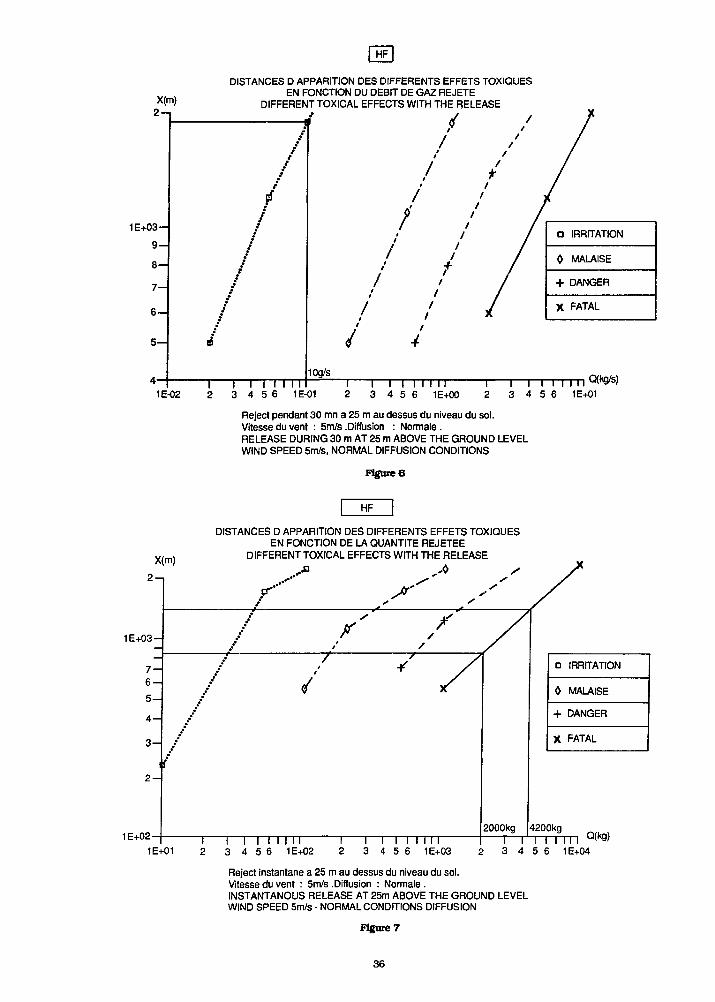
1E-02
X(m)
2 - ,
1E+03-
DISTANCES D APPARITION DES DIFFERENTS EFFETS TOXIQUESEN FONCTION DU DEBIT DE GAZ REJETE
DIFFERENT TOXICAL EFFECTS WITH THE RELEASE
10g/s
1 r I I I I3 4 5 6 1E-01
I I I I I I I I3 4 5 6 1E+00
Q(kg/s)
3 4 5 6 1E+01
Reject pendant 30 mn a 25 m au dessus du niveau du sol.Vitesseduvent : 5m/s.Diffusion : Normals.RELEASE DURING 30 m AT 25 m ABOVE THE GROUND LEVELWIND SPEED 5m/s, NORMAL DIFFUSION CONDITIONS
Figure 6
HF
DISTANCES D APPARITION DES DIFFERENTS EFFETS TOXIQUESEN FONCTION DE LA QUANTITE REJETEE
DIFFERENT TOXICAL EFFECTS WITH THE RELEASE
1E+02I I I I I I I I3 4 5 6 1E+02
D
0
+X
IRRITATION
MALAISE
DANGER
FATAL
1E+011 I I I I I I3 4 5 6 1E+03
1 I I I I I I I3 4 5 6 1E+04
Q(kg)
Reject instantane a 25 m au dessus du niveau du sol.Vitesse du vent : 5m/s .Diffusion : Normale .INSTANTANOUS RELEASE AT 25m ABOVE THE GROUND LEVELWIND SPEED 5m/s - NORMAL CONDITIONS DIFFUSION
Figure 7
36
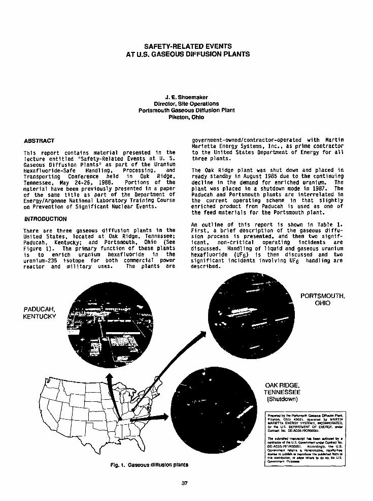
SAFETY-RELATED EVENTSAT U.S. GASEOUS DIFFUSION PLANTS
J. E. ShoemakerDirector, Site Operations
Portsmouth Gaseous Diffusion PlantPiketon, Ohio
ABSTRACT
This report contains material presented in thelecture entitled "Safety-Related Events at U. S.Gaseous Diffusion Plants" as part of the UraniumHexafluoride-Safe Handling, Processing, andTransporting Conference held in Oak Ridge,Tennessee, May 24-26, 1988. Portions of thematerial have been previously presented in a paperof the same title as part of the Department ofEnergy/Argonne National Laboratory Training Courseon Prevention of Significant Nuclear Events.
INTRODUCTION
There are three gaseous diffusion plants in theUnited States, located at Oak Ridge, Tennessee;Paducah, Kentucky; and Portsmouth, Ohio (SeeFigure 1). The primary function of these plantsis to enrich uranium hexafluoride in theuranium-235 Isotope for both commercial powerreactor and military uses. The plants are
PADUCAH,KENTUCKY
government-owned/contractor-operated with MartinMarietta Energy Systems, Inc., as prime contractorto the United States Department of Energy for allthree plants.
The Oak Ridge plant was shut down and placed inready standby in August 1985 due to the continuingdecline in the demand for enriched uranium. Theplant was placed in a shutdown mode in 1987. ThePaducah and Portsmouth plants are interrelated inthe current operating scheme In that slightlyenriched product from Paducah is used as one ofthe feed materials for the Portsmouth plant.
An outline of this report is shown in Table 1.First, a brief description of the gaseous diffu-sion process is presented, and then two signif-icant, non-critical operating incidents arediscussed. Handling of liquid and gaseous uraniumhexafluoride (UF6) 1s then discussed and twosignificant incidents involving UFg handling aredescribed.
PORTSMOUTH,OHIO
OAK RIDGE,TENNESSEE
(Shutdown)
Fig. 1. Gaseous diffusion plants
Praparad by tha Portsmouth Gasaout DBfMion Plan,Plkaton. Ohio 4SG61. oparatad by MARTINMARIETTA ENERGY SYSTEMS. INCORPORATED,lor tha US. DEPARTMENT OF ENERGY, undarContract No. DE-AC05-76OR00001.
Tha lubmktad manuscript hat baan authocad by •contractor or tha U.S. Govantmant undar Conrad No.DE-AC05-76OR00001. Accordingly, lha U.S.Govarnmant ratlins a nonaxckillva. roya)h/-fraalicanM to pubtittt or raproduca tha pubhhad lotm atthis contribution, or allow ottiars to do to. R» U.S.Govammam PurpOM*.
37
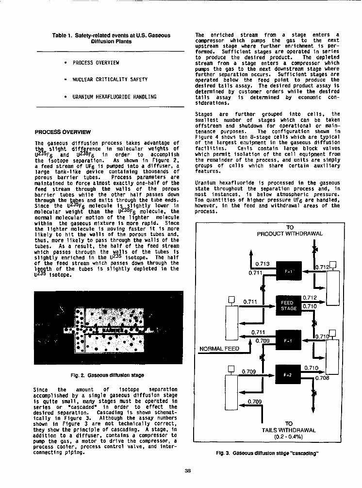
Table 1. Safety-related events at U.S. GaseousDiffusion Plants
PROCESS OVERVIEW
NUCLEAR CRITICALITY SAFETY
URANIUM HEXAFLUORIDE HANDLING
PROCESS OVERVIEW
The gaseous diffusion process takes advantage ofthe slight difference in molecular weights ofU" 5Fs and U238F6 1n order to accomplishthe Isotope separation. As shown in Figure 2,a feed stream of UF6 1s pumped Into a diffuser, alarge tank-like device containing thousands ofporous barrier tubes. Process parameters aremaintained to force almost exactly one-half of thefeed stream through the walls of the porousbarrier tubes while the other half passes down
bes and exits through the tube ends.5 lower 1n
6 molecule, thenormal molecular motion of the lighter moleculewithin the gaseous mixture 1s more rapid. Sincethe lighter molecule 1s moving faster it 1s morelikely to hit the walls of the porous tubes and,thus, more likely to pass through the walls of thetubes. As a result, the half of the feed streamwhich passes through the walls of the tubes 1sslightly enriched In the U 2 3 5 Isotope. The halfof the feed stream which passes down through the
barrier tubes while the other half pathrough the tubes and exits through the tSince the U235Fs molecule 1s slightlymolecular weight than the UZ38F6 mole
l l l ti f th liht
length of the tubes 1s slightly depleted in thei|235 Isotope.
Fig. 2. Gaseous diffusion stage
Since the amount of Isotope separationaccomplished by a single gaseous diffusion stageIs quite small, many stages must be operated inseries or "cascaded" In order to effect thedesired separation. Cascading 1s shown schemat-ically 1n Figure 3. Although the assay numbersshown In Figure 3 are not technically correct,they show the principle of cascading. A stage, inaddition to a diffuser, contains a compressor topump the gas, a motor to drive the compressor, aprocess cooler, process control valve, and Inter-connecting piping.
The enriched stream from a stage enters acompressor which pumps the gas to the nextupstream stage where further enrichment 1s per-formed. Sufficient stages are operated in seriesto produce the desired product. The depletedstream from a stage enters a compressor whichpumps the gas to the next downstream stage wherefurther separation occurs. Sufficient stages areoperated below the feed point to produce thedesired tails assay. The desired product assay 1sdetermined by customer orders while the desiredtails assay 1s determined by economic con-siderations.
Stages are further grouped into cells, thesmallest number of stages which can be takenoffstream and shutdown for operational or main-tenance purposes. The configuration shown inFigure 4 shows ten 8-stage cells which are typicalof the largest equipment in the gaseous diffusionfacilities. Ceils contain large block valveswhich permit Isolation of the cell equipment fromthe remainder of the process, and units are simplygroups of cells which share certain auxiliaryfeatures.
Uranium hexafluoride is processed in the gaseousstate throughout the separation process and, inmost instances, 1s below atmospheric pressure.Ton quantities of higher pressure UFg are handled,however, in the feed and withdrawal areas of theprocess.
TOPRODUCT WITHDRAWAL
Do:
NORMAL FEED
0.709
TOTAILS WITHDRAWAL
(0.2 - 0.4%)
Fig. 3. Gaseous diffusion stage "cascading"
38
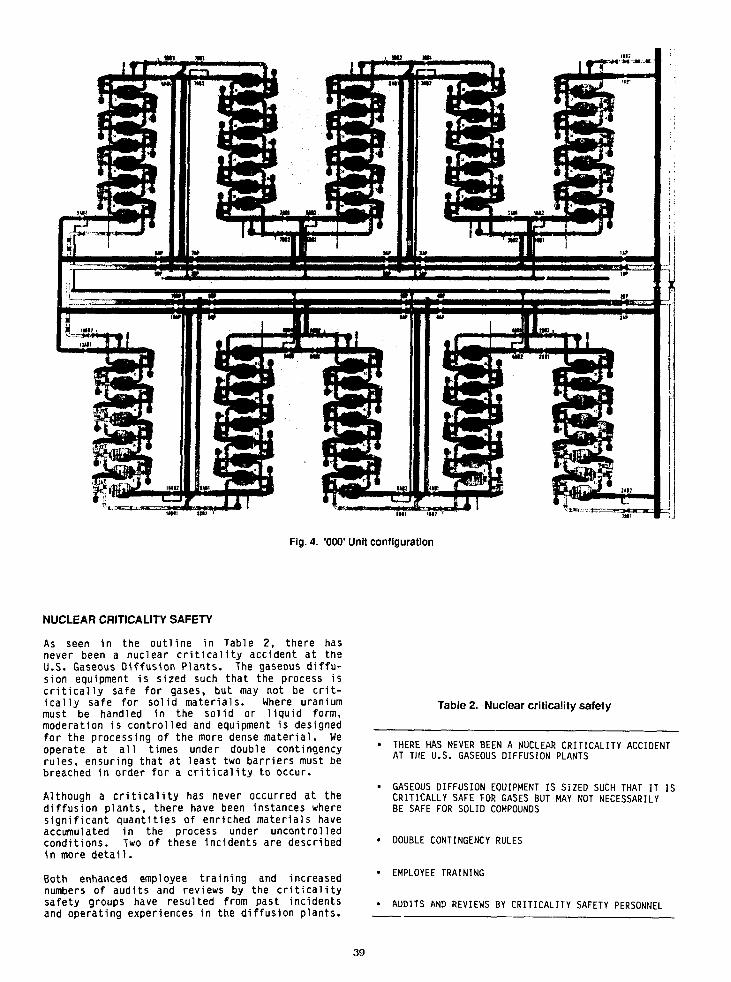
Fig. 4. '000' Unit configuration
NUCLEAR CRITICALITY SAFETY
As seen in the outline in Table 2, there hasnever been a nuclear criticality accident at theU.S. Gaseous Diffusion Plants. The gaseous diffu-sion equipment is sized such that the process iscritically safe for gases, but may not be crit-ically safe for solid materials. Where uraniummust be handled in the solid or liquid form,moderation is controlled and equipment is designedfor the processing of the more dense material. Weoperate at all times under double contingencyrules, ensuring that at least two barriers must bebreached in order for a criticality to occur.
Although a criticality has never occurred at thediffusion plants, there have been instances wheresignificant quantities of enriched materials haveaccumulated in the process under uncontrolledconditions. Two of these incidents are describedin more detail.
Both enhanced employee training and increasednumbers of audits and reviews by the criticalitysafety groups have resulted from past incidentsand operating experiences in the diffusion plants.
Table 2. Nuclear criticality safety
THERE HAS NEVER BEEN A NUCLEAR CRITICALITY ACCIDENTAT THE U.S. GASEOUS DIFFUSION PLANTS
GASEOUS DIFFUSION EQUIPMENT IS SIZED SUCH THAT IT ISCRITICALLY SAFE FOR GASES BUT MAY NOT NECESSARILYBE SAFE FOR SOLID COMPOUNDS
• DOUBLE CONTINGENCY RULES
• EMPLOYEE TRAINING
• AUDITS AND REVIEWS BY CRITICALITY SAFETY PERSONNEL
39
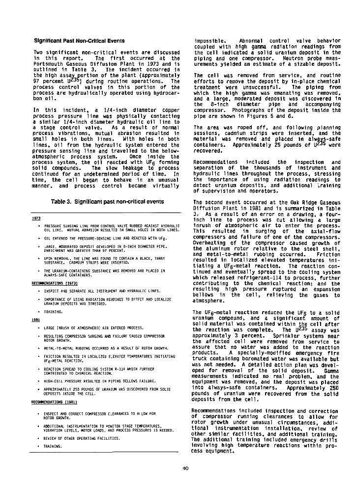
Significant Past Non-Crltlcal Events
Two significant non-critical events are discussedin this report. The first occurred at thePortsmouth Gaseous Diffusion Plant in 1973 and isoutlined in Table 3. The incident occurred inthe high assav portion of the plant (approximately97 percent U"=) during routine operations. Theprocess control valves in this portion of theprocess are hydraulically operated using hydrocar-bon oil.
In this incident, a 1/4-inch diameter copperprocess pressure line was physically contactinga similar 1/4-inch diameter hydraulic oil line toa stage control valve. As a result of normalprocess vibrations, mutual abrasion resulted insmall holes in both lines. With holes in bothlines, oil from the hydraulic system entered thepressure sensing line and travelled to the below-atmospheric process system. Once inside theprocess system, the oil reacted with UFg formingsolid compounds. The slow leakage to processcontinued for an undetermined period of time. Intime, the cell began to behave in an unusualmanner, and process control became virtually
Table 3. Significant past non-critical events
• PRESSURE SENSING LINE FROM CONTROL VALVE RUBBED AGAINST HYDRAULICOIL LINE. MUTUAL ABRASION RESULTED IN SMALL HOLES IN BOTH LINES.
• OIL ENTEREO THE PRESSURE-SENSING LINE AND REACTED WITH UF6.
• LARGE, MODERATED OEPOSIT DEVELOPED IN 8-INCH DIAMETER PIPE.ENRICHMENT WAS GREATER THAN 97 PERCENT.
• UPON REMOVAL, THE LINE WAS FOUND TO CONTAIN A BLACK, TARRYSUBSTANCE. CADMIUM STRIPS WERE INSERTED.
• THE URANIUM-CONTAINING SUBSTANCE WAS REMOVED AND PLACED INALWAYS-SAFE CONTAINERS.
RECOMMENDATIONS (1973)
• INSPECT AND SEPARATE ALL INSTRUMENT AND HYDRAULIC LINES.
• IMPORTANCE OF USING RADIATION READINGS TO DETECT AND LOCALIZEURANIUM DEPOSITS WAS STRESSED.
1981
• LARGE INRUSH OF ATMOSPHERIC AIR ENTERED PROCESS.
• RESULTING COMPRESSOR SURGING AND FAILURE CAUSED COMPRESSORROTOR GROWTH.
• METAL-TO-METAL RUBBING OCCURRED AS A RESULT OF ROTOR GROWTH.
• FRICTION RESULTED IN LOCALIZED ELEVATED TEMPERATURES INITIATINGUFs-METAL REACTION.
• REACTION SPREAD TO COOLING SYSTEM R-U4 WHICH FURTHERCONTRIBUTED TO CHEMICAL REACTION.
• HIGH-CELL PRESSURE RESULTED IN PIPING BELLOWS FAILURE.
• APPROXIMATELY 250 POUNDS OF URANIUM WAS DISCOVERED FROM SOLIDDEPOSITS INSIDE THE CELL.
RECOMMENDATIONS (1981)
INSPECT AND CORRECT COMPRESSOR CLEARANCES TO ALLOW FORROTOR GROWTH.
ADDITIONAL INSTRUMENTATION TO MONITOR STAGE TEMPERATURES,VIBRATION LEVELS, MOTOR LOADS, AND PROCESS PRESSURES IS NEEDED.
REVIEW OF OTHER OPERATING FACILITIES.
TRAINING.
impossible. Abnormal control valve behaviorcoupled with high gamma radiation readings fromthe cell indicated a solid uranium deposit in thepiping and one compressor. Neutron probe meas-urements yielded an estimate of a sizable deposit.
The cell was removed from service, and routineefforts to remove the deposit by in-piace chemicaltreatment were unsuccessful. The piping fromwhich the high gamma was emanating was removed,and a large, moderated deposit was discovered inthe 8-1nch diameter pipe and accompanyingcompressor. Photographs of the deposit inside thepipe are shown in Figures 5 and 6.
The area was roped off, and following planningsessions, cadmium strips were Inserted, and thematerial was removed and placed In always-safecontainers. Approximately 25 pounds of U " 5 wererecovered.
Recommendations Included the inspection andseparation of the thousands of instrument andhydraulic lines throughout the process, stressingthe Importance of using radiation readings todetect uranium deposits, and additional '..rainingof supervision and operators.
The second event occurred at the Oak Ridge GaseousDiffusion Plant in 1981 and is summarized in Table3. As a result of an error on a drawing, a four-inch line to process was cut allowing a largeinrush of atmospheric air to enter the process.This resulted in surging of the axial-flowcompressors and failure of one of the compressors.Overheating of the compressor caused growth ofthe aluminum rotor relative to the steel shell,and metal-to-metal rubbing occurred. Frictionresulted in localized elevated temperatures ini-tiating a UF6-metal reaction. The reaction con-tinued and eventually spread to the cooling systemwhich released refrigerant-114 to process, furthercontributing to the chemical reaction; and theresulting high pressure ruptured an expansionbellows in the cell, relieving the gases toatmosphere.
The UFg-metal reaction reduced the UF6 to a soliduranium compound, and a significant amount ofsolid material was contained within the cell afterthe reaction was complete. The U 2 3 5 assay wasapproximately 3 percent. Sprinkler systems nearthe affected cell were removed from service toassure that no water was added to the reactionproducts. A specially-modified emergency firetruck containing boronated water was available butwas not needed. A detailed action plan was devel-oped for removal of the solid deposit. Gammameasurements indicated no real problem, and theequipment was removed, and the deposit was placedinto always-safe containers. Approximately 250pounds of uranium were recovered from the soliddeposits from the cell.
Recommendations Included Inspection and correctionof compressor running clearances to allow forrotor growth under unusual circumstances, addi-tional instrumentation Installation, review ofother similar facilities, and additional training.The additional training included emergency drillsInvolving high temperature reactions within pro-cess equipment.
40

Fig. 5. Process pip* containing UFg/hydrocarbonreaction products
vsin— NUfXEAK CAT1CAUTY SAFETY
'" •"' EMPUYEE TMWME REPORT
" " " "
CMf^K) ><rul> M TOUMI IWH*.
*.b.c».™ M «-, .- M M ( « « ,™.. ......
KnurctM BH H COWKM .t.«nit.» M pMHf.cii'r «»rt to"w>w» •" v*«* *tn.
aw<Un<* el aiiuM *i»y cniww, Ms ID ̂ angrii »rtr«>i u u r i ma -s™ m u .
19. MpratM iwj f i ( n m i i . i»w M i x i p n •>• »0M' >ww»i>°" o< uniti itulcfwii M a* irn-i AUBM. of un:li
11. Liuu iM ifimitmt o' "(MihoniK «»«ni" m I W I W L
U. -fv-ftt.****,,'OHM, ***,«,*****..
TntitwnlbtnoanutisnimoettitiiilPitcMkini. a" cn»^*nnec*ji.B|B«)c«*i-n«uH t» tenj.Hr »«*«= "r * •11. NUCIMI &•*«"» hftly few.
It. M.MV!im>MHt)iilMH»<H<.
DM
no ha oneritM lanMimlT »i « * awcHM t..«i.un • e K w atw «• »i»ii J «•» - nM"<"""> *"* *' * * " •""""' « » " • ' '
Fig. 7. Nuclear critlcallty safety employee training report
Fig. 6. Process pipe containing UFg/hydrocarbonreaction products
Employee Training
Salaried and hourly employees who handle fissilematerials receive classroom training annually onthe general principles of crit lcallty safety.Both the employee and his supervisor then signthe form shown 1n Figure 7 following training.Specific on-the-job training 1n crit lcallty safety1s accomplished 1n the field In addition to theclassroom work.
Audits and Reviews by Critlcallty SafetyProfessional Staff
Figure B shows the form utilized by critlcalltysafety personnel 1n performing routine, 1n-plantaudits. The audit schedule Is computerized andoutlines the monthly audit requirements.Following the audit, the Incident report Iscompleted and presented to plant supervisionresponsible for the area audited. Findings withseverity Indices of 2 and above are also presentedto plant management. Audit severity Indices arestatistically studied to determine trends andareas needing particular attention.
CRmCALITY SAFETY AUDIT/INCIDENT REPORT1 "" "''"""•- LOCATION ft OHH«T1O«
(.N.MC Of OflflATIO, CONTACT
' D » " O " « ' 0 * » » |tJ.OlTICT.OKl
1'°"'°G«o ,I.-«O-
G MONMOU
* D fU«Tr
M l t e l b n ) 14 . . ,c
MKI G HOUI'MI
O i O M I l • IHC1.N
G OTHIK -snztf
O<lWl l (U 1MB
G*"**O<*<*t!Unla
QFmh «•••»••(.
G InarwnHsn to D*B>
G hwflsMnt Tmnmf
D I * » I I B I H I rlnnn
Qt46 FMVMl u NAG WltMn tggnM tWiioG Wr>Br O » Ota I H KQ SfjU Be** I OHM On* «**l>Q OavH* • « * a. 0-»
QvnuUfa-QUO*
D o n
QiwiiG*1H1Otan
'TIT"™ []liv<i««iirniiC«Wwi
•mrMon Q i l l ll HJUMI n—.1
Fig. 8. Critlcallty safety Incident report
41
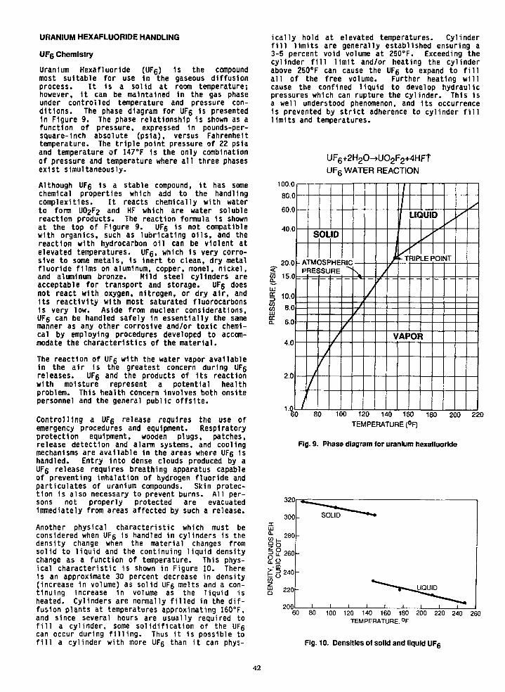
URANIUM HEXAFLUORIDE HANDLING
U F 6 Chemistry
Uranium Hexafluorlde (UFg) 1s the compoundmost suitable for use 1n the gaseous diffusionprocess. It 1s a solid at room temperature;however, it can be maintained In the gas phaseunder controlled temperature and pressure con-ditions. The phase diagram for UF6 is presentedin Figure 9. The phase relationship is shown as afunction of pressure, expressed in pounds-per-square-1nch absolute (psia), versus Fahrenheittemperature. The triple point pressure of 22 psiaand temperature of 147°F 1s the only combinationof pressure and temperature where all three phasesexist simultaneously.
Although UFg 1s a stable compound, it has somechemical properties which add to the handlingcomplexities. It reacts chemically with waterto form UO2F2 and HF which are water solublereaction products. The reaction formula 1s shownat the top of Figure 9. UFg 1s not compatiblewith organics, such as lubricating oils, and thereaction with hydrocarbon oil can be violent atelevated temperatures. UFg, which 1s very corro-sive to some metals, is inert to clean, dry metalfluoride films on aluminum, copper, monei, nickel,and aluminum bronze. Mild steel cylinders areacceptable for transport and storage. UFg doesnot react with oxygen, nitrogen, or dry air, andIts reactivity with most saturated fluorocarbons1s very low. Aside from nuclear considerations,UFg can be handled safely 1n essentially the samemanner as any other corrosive and/or toxic chemi-cal by employing procedures developed to accom-modate the characteristics of the material.
The reaction of UFg with the water vapor available1n the air 1s the greatest concern during UFgreleases. UFg and the products of Its reactionwith moisture represent a potential healthproblem. This health concern Involves both onsitepersonnel and the general public offsite.
Controlling a UFg release requires the use ofemergency procedures and equipment. Respiratoryprotection equipment, wooden plugs, patches,release detection and alarm systems, and coolingmechanisms are available in the areas where UFg 1shandled. Entry into dense clouds produced by aUFg release requires breathing apparatus capableof preventing inhalation of hydrogen fluoride andparticulates of uranium compounds. Skin protec-tion is also necessary to prevent burns. All per-sons not properly protected are evacuatedimmediately from areas affected by such a release.
Another physical characteristic which must beconsidered when UFg is handled in cylinders 1s thedensity change when the material changes fromsolid to liquid and the continuing liquid densitychange as a function of temperature. This phys-ical characteristic is shown in Figure 10. Thereis an approximate 30 percent decrease in density(increase in volume) as solid UFg melts and a con-tinuing Increase in volume as the liquid isheated. Cylinders are normally filled in the dif-fusion plants at temperatures approximating 160°F,and since several hours are usually required tofill a cylinder, some solidification of the UFgcan occur during filling. Thus it is possible tofill a cylinder with more UFg than it can phys-
ically hold at elevated temperatures. Cylinderfill limits are generally established ensuring a3-5 percent void volume at 250°F. Exceeding thecylinder fill limit and/or heating the cylinderabove 250°F can cause the UFg to expand to fillall of the free volume. Further heating willcause the confined liquid to develop hydraulicpressures which can rupture the cylinder. This isa well understood phenomenon, and its occurrence1s prevented by strict adherence to cylinder filllimits and temperatures.
100.0
80.0
60.0
40.0
_ 20.0
UJ
§ 10.0w 8.0UJ
E 6.0
4.0
2.0
1.0
- A
s
TMf
UF6+2H2O^UO2F2+4HFTUF6 WATER REACTION
OLID
U P
PRESSURE ^
1
/
/
/
k/
/ • •
1
i
VAP
LIC
HP
OF
IUI
y_EF
\
3
'OK
/
>4T
60 80 100 120 140 160 180 200 220TEMPERATURE (°F)
Fig. 9. Phase diagram for uranium hexafluorlde
320
60 80 100 120 140 160 180 200 220 240 260TEMPERATURE. °F
Fig. 10. Densities of solid and liquid UF6
42
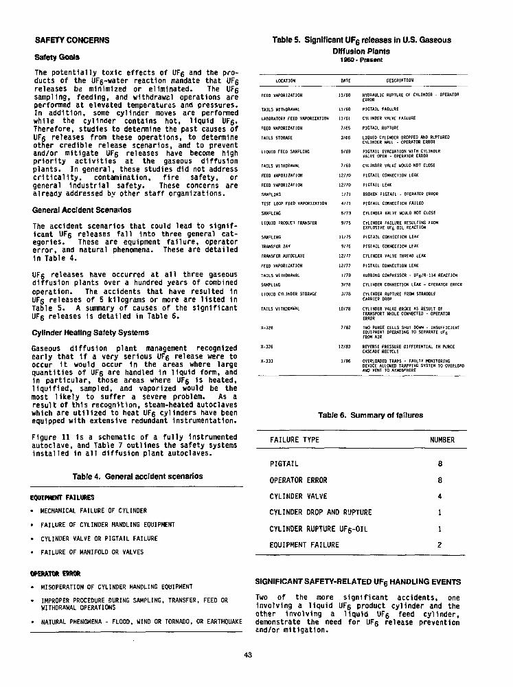
SAFETY C O N C E R N S
Safety Goals
The potentially toxic effects of UFg and the pro-ducts of the UF6-water reaction mandate that UFgreleases be minimized or eliminated. The UFgsampling, feeding, and withdrawal operations areperformed at elevated temperatures and pressures.In addition, some cylinder moves are performedwhile the cylinder contains hot, liquid UFg.Therefore, studies to determine the past causes ofUFg releases from these operations, to determineother credible release scenarios, and to preventand/or mitigate UFg releases have become highpriority activities at the gaseous diffusionplants. In general, these studies did not addresscNticality, contamination, fire safety, orgeneral industrial safety. These concerns arealready addressed by other staff organizations.
General Accident Scenarios
The accident scenarios that could lead to signif-icant UFg releases fall Into three general cat-egories. These are equipment failure, operatorerror, and natural phenomena. These are detailed1n Table 4.
UFg releases have occurred at all three gaseousdiffusion plants over a hundred years of combinedoperation. The accidents that have resulted 1nUFg releases of 5 kilograms or more are listed inTable 5. A summary of causes of the significantUFg releases 1s detailed In Table 6.
Cylinder Heating Safety Systems
Gaseous diffusion plant management recognizedearly that 1f a very serious UFg release were tooccur it would occur in the areas where largequantities of UFg are handled 1n liquid form, andin particular, those areas where UFg Is heated,liquified, sampled, and vaporized would be themost likely to suffer a severe problem. As aresult of this recognition, steam-heated autoclaveswhich are utilized to heat UFg cylinders have beenequipped with extensive redundant Instrumentation.
Figure 11 is a schematic of a fully instrumentedautoclave, and Table 7 outlines the safety systemsinstalled in all diffusion plant autoclaves.
Table 4. General accident scenarios
EQUIPHEHT FAILURES
• MECHANICAL FAILURE OF CYLINDER
• FAILURE OF CYLINDER HANDLING EQUIPMENT
• CYLINDER VALVE OR PIGTAIL FAILURE
• FAILURE OF MANIFOLD OR VALVES
Table 5. Significant UF6 releases in U.S. Gaseous
Diffusion PlantsI960-Present
LOCATION
FEED VAPORIZATION
TAILS WITHDRAWAL
LABORATORY FEED VAPORIZATION
FEED VAPORIZATION
TAILS STORAGE
LIQUID FEED SAMPLING
TAILS WITHDRAWAL
FEED VAPORIZATION
FEEO VAPORIZATION
SAMPLING
TEST LOOP FEED VAPORIZATION
SAMPLING
LIQUID PRODUCT TRANSFER
SAMPLING
TRANSFER BAY
TRANSFER AUTOCLAVE
FEED VAPORIZATION
TAILS WITHDRAWAL
SAMPLING
LIQUID CVLINDER STORAGE
TAILS WITHDRAWAL
X-326
X-326
X-333
OATE
11/60
11/60
11/61
7/65
3/66
5/69
7/69
12/70
12/70
1/71
4/71
5/73
9/75
11/75
9/76
12/77
12/77
1/76
3/78
3/78
10/78
7/82
12/83
1/86
DESCRIPTION
HYDRAULIC RUPTURE OF CYLINDER - 0PERAT08ERROR
PIGTAIL FAILURE
CYLINDER VALVE FAILURE
PIGTAIL RUPTURE
LIQUID CYLINDER DROPPED AND RUPTUREDCYLINDER WALL - OPERATOR ERROR
PIGTAIL EVACUATION WITH CYLINDERVALVE OPEN - OPERATOR ERROR
CYLINDER VALVE WOULD NOT CLOSE
PIGTAIL CONNECTION LEAK
PIGTAIL LEAK
BROKEN PIGTAIL - OPERATOR ERROR
PIGTAIL CONNECTION FAILED
CYLINDER VALVE WOULD NOT CLOSE
CYLINDER FAILURE RESULTING FROMEXPLOSIVE UF6 OIL REACTION
PIGTAIL CONNECTION LEAK
PIGTAIL CONNECTION LEAK
CYLINDER VALVE THREAD LEAK
PIGTAIL CONNECTION LEAK
RUBBING COMPRESSOR - UF6/R-114 REACTION
CYLINDER CONNECTION LEAK - OPERATOR ERROR
CYLINDER RUPTURE FROM STRADDLECARRIER DROP
CYLINDER VALVE 8RDKE AS RESULT OFTRANSPORT WHILE CONNECTED - OPERATORERROR
TWO PURGE CELLS SHUT DOWN - INSUFFICIENTEQUIPMENT OPERATING TO SEPARATE UF6FROM AIR
REVERSE PRESSURE DIFFERENTIAL IN PURGECASCADE RECYCLE
OVERLOADED TRAPS - FAULTY MONITORINGDEVICE ALLOWED TRAPPING SYSTEM TO OVERLOADAND VENT TO ATMOSPHERE
Table 6. Summary of failures
FAILURE TYPE NUMBER
PIGTAIL
OPERATOR ERROR
CYLINDER VALVE
CYLINDER DROP AND RUPTURE
CYLINDER RUPTURE UFg-OIL
EQUIPMENT FAILURE
8
8
4
1
1
2
OPERATOR ERROR
• MISOPERATION OF CYLINDER HANDLING EQUIPMENT
• IMPROPER PROCEDURE DURING SAMPLING, TRANSFER, FEED ORWITHDRAWAL OPERATIONS
• NATURAL PHENOMENA - FLOOD, WIND OR TORNADO, OR EARTHQUAKE
SIGNIFICANT SAFETY-RELATED U F 6 HANDLING EVENTS
Two of the more significant accidents, oneInvolving a liquid UFg product cylinder and theother involving a liquid UFg feed cylinder,demonstrate the need for UFg release preventionand/or mitigation.
43
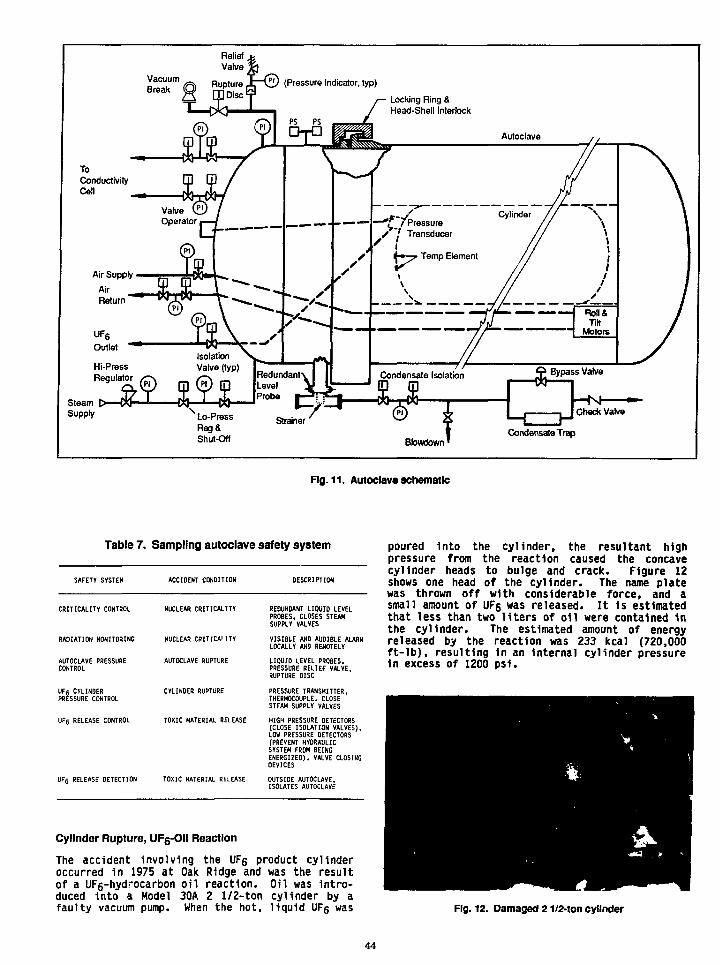
ReliefValve
ToConductivityCell
SteamSupply
Locking Ring &Head-Shell Interlock
Lo-PressReg&Shut-Oft Bbwdown <
Condensate Trap
Fig. 11. Autoclave schematic
Table 7. Sampling autoclave safety system
SAFETY SYSTEM ACCIDENT CONDITION DESCRIPTION
CRITICALITY CONTROL
RADIATION MONITORING
AUTOCLAVE PRESSURECONTROL
UF6 CYLINDERPRESSURE CONTROL
RELEASE CONTROL
UF6 RELEASE DETECTION
NUCLEAR CRITICALITY
NUCLEAR CBITICAL1TY
AUTOCLAVE RUPTURE
CYLINDER RUPTURE
TOXIC MATERIAL RELEASE
TOXIC MATERIAL RELEASE
REDUNDANT LIQUID LEVELPROBES, ClOSES STEAMSUPPLY VALVES
VISIBLE AND AUDIBLE ALARMLOCALLY AND REMOTELY
LIQUID LEVEL PROBES,PRESSURE RELIEF VALVE,RUPTURE DISC
PRESSURE TRANSMITTER,THERMOCOUPLE, CLOSESTEAM SUPPLY VALVES
HIGH PRESSURE DETECTORS(CLOSE ISOLATION VALVES).LOW PRESSURE DETECTORS(PREVENT HYDRAULICSYSTEM FROM BEINGENERGIZED). VALVE CLOSINGDEVICES
OUTSIDE AUTOCLAVE.ISOLATES AUTOCLAVE
Cylinder Rupture, UF6-Oll Reaction
The accident involving the UF6 product cylinderoccurred in 1975 at Oak Ridge and was the resultof a UF6-hydrocarbon oil reaction. Oil was Intro-duced into a Model 30A 2 1/2-ton cylinder by afaulty vacuum pump. When the hot, liquid UFg was
poured Into the cylinder, the resultant highpressure from the reaction caused the concavecylinder heads to bulge and crack. Figure 12shows one head of the cylinder. The name platewas thrown off with considerable force, and asmall amount of UFs was released. It is estimatedthat less than two liters of oil were contained inthe cylinder. The estimated amount of energyreleased by the reaction was 233 kcal (720,000ft-lb), resulting In an Internal cylinder pressurein excess of 1200 psi.
Fig. 12. Damaged 21/2-ton cylinder
44

Recommendations from the Incident Included theexclusion of oil filled vacuum pumps for evac-uation of UFg cylinders. The evacuation of cylin-ders must be accomplished with equipment such asair ejectors. Also, quality assurance plans wereprepared for cylinder decontamination, evacuation,and valve Installation.
Findings and recommendations from this Incidentwere made available to nuclear Industry licenseesand vendors Involved 1n UF5 handling. This Inci-dent 1s documented 1n report "./P-6197, Revision 1,"Investigation of a Uranium Hexafluoride ReleaseIncident on September 17, 1975, In the K-1423 TollEnrichment Facility," April 16, 1986.
Fourteen-Ton Feed Cylinder Drop
An accident Involving a 14-ton feed cylinderoccurred 1n 1978. Details of this release aregiven In Figures 13 and 14. A 14-ton cylindercontaining liquid feed material was being movedfrom the sampling area at Portsmouth to thecool 1no yard. As the cylinder was being loweredfrom the straddle carrier to cylinder "saddles,"the cylinder fell 8-10 Inches resulting 1n an8-Inch long rupture In the cylinder wall.Essentially, the entire contents of the cylinderwere released.
Recommendations Included design and Installa-tion of a straddle carrier 11ft mechanism which
provides positive attachment to cylinders,Improved straddle carrier maintenance procedures,and Improved training In cylinder handling.
CONCLUSIONS
Conclusions and lessons learned are summarizedin Table 8. For many years we have dismissedaccidents as "operator error," disciplined theoperator, and considered the case closed. Overthe years we have learned that most "operatorerrors" are management Inspired by poor proce-dures, poor examples, and/or lack of propertraining courses, both classroom and on-the-job.Recent studies have shown that approximately 85percent of problems are "system problems" withonly 15 percent qualifying as true peopleproblems. Recognition of this fact and tacklingthe system problems Instead of finger pointing atIndividuals 1s the first step toward Improvedfacility safety. Focusing on system problemsIncludes training the work force thoroughly,audits by health and safety disciplines, visibleand enthusiastic upper management support ofhealth and safety, open communication, both ver-tically and horizontally, and learning from pastexperiences. Improving the overall system canhave a marked effect on facility safety perform-ance.
Fig. 13. Large UFg release from a 14-ton cylinder
45

CIRCUMSTANCES
- A STRADDLE CARRIER WAS BEING USED
- A MODEL 48G CYLINDER CONTAINING LIQUID UF6
WAS DROPPED FROM - 8 - 1 0 in. HIGH ONTO AWOODEN SADDLE
• THIN WALL 5/16 in. THICK
• NORMAL ASSAY UF6
• THREE, 1 in. THICK BY 2 1/2 in. WIDESTIFFENING RINGS
_ THE IMPACT RESULTED IN A RUPTURE IN THECYLINDER WALL ABOUT 1/2 in. WIDE AND 8 in. LONG
Fig. 14. Point of rupture, large UFg release from 14-ton cylinder
Table 8. Conclusions
85 PERCENT OF PROBLEMS ARE "SYSTEM PROBLEMS"; 15 PERCENTARE "OPERATOR ERROR"
WORKERS AND SUPERVISION MUST BE THOROUGHLY TRAINED IN ALLASPECTS OF THEIR JOB ASSIGNMENTS
PLANTWIDE AUDITS BY PRODUCTION PERSONNEL AND HEALTH ANDSAFETY DISCIPLINES ARE EXTREMELY IMPORTANT TO ENSURE THATPROCEDURES ARE ADEQUATE AND ARE BEING FOLLOWED
MANAGEMENT SUPORT OF HEALTH AND SAFETY CONCERNS MUST BEENTHUSIASTIC AND CONSPICUOUS
OPEN COMMUNCIATIONS MUST BE MAINTAINED AMONG MANAGEMENT,STAFF GROUPS, AND PRODUCTION EMPLOYEES
WE MUST LEARN FROM PAST EXPERIENCES
46
FEEDING UF6 WITHOUT LIQUEFACTION
AUTHORS
Jean-Marie RENEAUDOperations and Facility ManagerEURODIF, Tricastin, France
Jean-Luc SALANA VEAssistant to the Production ManagerEURODIF, Tricastin.France
ABSTRACT
In a gassous diffusion enrichment plant, like theGEORGES BESSE plant, uranium hexafluoridehas to be transformed from a solid to a gaseousstate in order to be fed into the cascade. Twodifferent processes are available.
The first one is based on liquefaction and highpressure evaporation. Its advantages are: firstlysufficient UF6 pressure to directly feed thecascade, and secondly high flow rates. Its onedisadvantage comes from the physical propertiesof UF6: the liquefaction pressure isoveratmospheric (up to 6 absolute bars in someoperating conditions), and this creates safetyconcerns with regards to certain cylinders andother equipment.
The second process simply consists of directsublimation of UF6. It allows UF6 to stay atsubatmospheric pressure, but this low pressurecan be incompatible with the cascade feedpressure and the sublimation flow rate is lowerthan that of evaporation.
This paper describes how a feed process using thelow pressure sublimation of solid UF6 has beendevelopped and adapted to a gaseousplant.resulting in net flow rate performancesalmost equivalent to the ones obtained from aprocess using UF6 liquefaction.
The solid feed materiel is shipped using differenttypes of model 48 cylinders. These cylinders areplaced in air-heated ovens. The UF6 issublimated and fed into the cascade throughvacuum spiral-pumps.
Two feeding modes by sublimation are beingused: in the first one, which is the most used, theoven temperature is 115°C and the net flow rateis 50 grams of UF6 per second and per feed cell(versus 60 g/s for the liquefaction mode). In thesecond one, the air temperature is limited to 85°Cin order to avoid liquefaction of UF6 in anycircumstances; then the net flow rate is only25-30 g/s of UF6 per feed cell.
This process has received the approval of theSafety Authorities.
CONTENTS
1 - Introduction2 - Historical development of the Eurodif
feed process3 - Equipment description
3.1. Ovens3.2. Filters3.3. Process lines3.4. Pumps3.5. Building and miscellaneous equipment
4 - Process operation4.1. Working principles4.2. Computerized operating procedures4.3. Monitoring
5 * Operating experience5.1. Process performances5.2. Equipment5.3. Lessons learnt from incidents
6 • Conclusions.
1- INTRODUCTION
The GEORGES BESSE Gaseous DiffusionUranium Enrichment plant located in Tricastin,France, has an enrichment capacity of 10.8million Separative Work Units per year. Begunin 1974 and completed in 1982, the plant isoperated by EURODIF PRODUCTION, asubsidiary of EURODIF S.A. which is composedof the following partners: COGEMA (France),SYNATOM (Belgium), ENUSA (Spain), ENEA(Italy) and AGIP (Italy), SOFIDIF (Franco-Iranian) :
© EURODIF S.A.
Figure 1. EURODIF S-A.
47
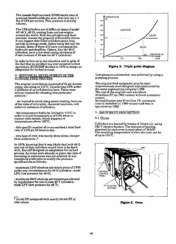
The cascade feed can reach 35000 metric tons ofuranium hexafluoride per year, that is to say 1.1Kg of UF6 per second. This uranium is mainlynatural.
The UF6 cylinders are of different types of model48 (48 Y, 48 G), coming from various originsaround the world. Both the cylinders and theircontents remain the property of Eurodif s clients.It can happen that filled cylinders spend longperiods in storage yards, before being fed into thecascade. Some of them will have overstayed thehydraulic test deadline. Others, like the 48 Gcylinders, have a low steel casing thickness of8 mm (instead of 16 mm for 48 Y cylinders).
In order to face up to any situation and in spite ofthe fact that no accident has ever occurred in feedoperations, EURODIF decided in 1979 to design anadaptation for its feed process.
2 - HISTORICAL DEVELOPMENT OF THEEURODIF FEED PROCEgg
The original installation consisted of 24 air-heatedovens operating at 115°C, liquefacting UF6 undera pressure of up to 6 absolute bars. There wereseveral reasons for choosing this particularsolution:
- we wanted to avoid using steam heating, becauseof the risks of criticality, chemical reactions, andexternal corrosion of cylinders,
- the temperature had to be limited to 115°C inorder to avoid decomposition of UF6 when incontact with metals, which happens attemperatures above 120°C,
- this specific number of ovens enabled a total feedrate of 1100 g/s 24 hours a day,
- this type of oven was nearly three times cheaperthan autoclaves .*
In 1979, knowing that it was likely that both 48 Gand out-of-date cylinders would have to be dealtwith, Eurodif designed an adaptation for its feedprocess. As ovens were already in place, the idea ofinvesting in autoclaves was not selected. It wasconsidered preferable to modify the pressurespecifications as follows:
- maximum 1500 absolute mb (triple point of UF6)under any circumstances for 48 G cylinders : modeLPG (low pressure for 48 G).
- maximum 5000 absolute mb (maximum allowedby regulations) for out-of-date 48 Y cylinders:mode LPY (low pressure for 48 Y).
* 210 000 FF compared with nearly 620 000 FF at1980 values
140-
120-
100-
80-
6 0 -
40-
20-
0 -
TEMPERATURE°C
W9
GASEOUS
100
y
soLID
1548
1000
/
LIQUID
PRESSURE mb
10000
Figure 2. Triple point diagram
Low pressure sublimation was achieved by using apumping process.
The original feed equipment plus its laterimprovements were designed and constructed bythe same engineering company USSI.The cost of the original unit was about50 million FF (at 1980 values) without automaticcontrol.Its modification cost 30 million FF, automaticcontrol included (at 1980 values) and was in
operation by 1982.
3 - EQUIPMENT DESCRIPTION
3.1. OvensCylinders are heated by means of blown air, using380 V electric heaters. The amount of heatingabsorbed by each oven is equivalent of 30 kW.The resulting temperature within the oven can beofuptol20°C.
n^M(j(B^—«^,<- F A N
/ *Jr- HEATING n
CONTROL y
^— ELECTRIC H *HEATERS
TO
ii
V
" 1—
1
Figure 3. Oven
48
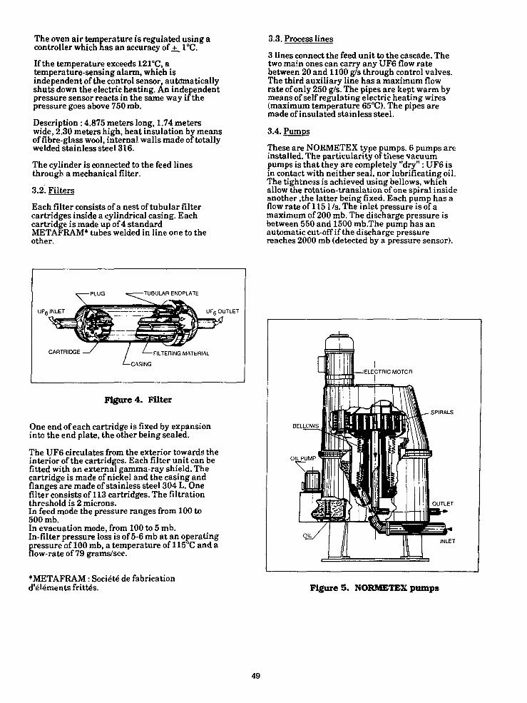
The oven air temperature is regulated using acontroller which has an accuracy of ±_ 1°C.
If the temperature exceeds 121°C, atemperature-sensing alarm, which isindependent of the control sensor, automaticallyshuts down the electric heating. An independentpressure sensor reacts in the same way if thepressure goes above 750 mb.
Description : 4.875 meters long, 1.74 meterswide, 2.30 meters high, heat insulation by meansof fibre-glass wool, internal walls made of totallywelded stainless steel 316.
The cylinder is connected to the feed linesthrough a mechanical filter.
3.2. Filters
Each filter consists of a nest of tubular filtercartridges inside a cylindrical casing. Eachcartridge is made up of 4 standardMETAFRAM* tubes welded in line one to theother.
3.3. Process lines
3 lines connect the feed unit to the cascade. Thetwo main ones can carry any UF6 flow ratebetween 20 and 1100 g/s through control valves.The third auxiliary line has a maximum flowrate of only 250 g/s. The pipes are kept warm bymeans of self regulating electric heating wires(maximum temperature 65°C). The pipes aremade of insulated stainless steel.
These are NORMETEX type pumps. 6 pumps areinstalled. The particularity of these vacuumpumps is that they are completely "dry": UF6 isin contact with neither seal, nor lubrificating oil.The tightness is achieved using bellows, whichallow the rotation-translation of one spiral insideanother ,the latter being fixed. Each pump has aflow rate of 1151 /s. The inlet pressure is of amaximum of 200 mb. The discharge pressure isbetween 550 and 1500 mb.The pump has anautomatic cut-off if the discharge pressurereaches 2000 mb (detected by a pressure sensor).
-^—PLUG
CARTRIDGE — '
.. TUBULAR ENDPLATE
/ / ^ ^ ^/ '—FILTERING MATERIAL
^-CASING
Figure 4. Filter
One end of each cartridge is fixed by expansioninto the end plate, the other being sealed.
The UF6 circulates from the exterior towards theinterior of the cartridges. Each filter unit can befitted with an external gamma-ray shield. Thecartridge is made of nickel and the casing andflanges are made of stainless steel 304 L. Onefilter consists of 113 cartridges. The filtrationthreshold is 2 microns.In feed mode the pressure ranges from 100 to500 mb.In evacuation mode, from 100 to 5 mb.In-filter pressure loss is of 5-6 mb at an operatingpressure of 100 mb, a temperature of 115°C and aHow-rate of 79 grams/sec.
*METAFRAM: Societe de fabrication({'elements frittes.
- SPIRALS
INLET
Figure 5. NORMETEX pumps
49
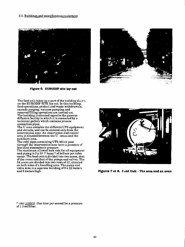
3.5. Buildings and miscellaneous equipment
Figure 6. EURODEF site lay-out
The feed unit takes up a part of the building shownon the EURODIF SITE lay out. In this building,feed operations, product and waste withdrawals,cascade purging, vacuum pumping andremoval/filling operations are carried out.The building is situated opposite the gaseousdiffusion facility to which it is connected by atechnical gallery which contains processconnection pipes.The U area contains the different UF6 equipmentand circuits, and can be entered only from theintervention zone. An observation and controlarea is situated between the U - areas and theauxiliary area.The only pipes containing UF6 which passthrough the intervention zone have a pressure ofless than atmospheric pressure.The maximum allowed leak rate for all equipmentand piping is 2 x 10 -2 lusec * of helium per cubicmeter. The feed unit is divided into two zones, thatof the ovens and that of the pumps and valves. The24 ovens are divided into two rows of 12, situatedon both sides of a handling area. The pump andvalve zone is a separate building of 9 x 22 metersand 9 meters high. Figures 7 et 8. Feed Unit - The area and an oven
* 1000 LUSECS : One liter per second for a pressureof 1.3 millibar.
50

4- PROCESS OPERATION
4.1. Working principles
Each of the 3 feed lines F, G and H can operateeither in HP (high pressure) or in LP (lowpressure) mode. Operating control is carried outfrom the central control room which is situated ina different building from that of the feed unit.
The control systems consist of:- synoptic graphic displays,- continually-updated on-screen messages- control software for the ovens and vacuumpumps.
Figure 9. Control room
Connecting and disconnecting of cylinders iscarried out on the order of the control room. Thenecessary dialogue between the system and ovenpersonnel is achieved using a visual indicator andswitch panel.Although the central system controls all electrics,vacuum pumps, valves etc... this control can behandled manually in the facility.
Figure 10. Oven control panel
The operational choices in the control room arethe following:. Individual control of each piece of equipment.. Control of basic sequences concerning pumps,ovens and flow captors.. Control of the series of operations which makeup the in-oven cycle for any cylinder.. Control of the complete management program
for the three different feeds F,G,H.
4.2. Computerized operating procedures
Three automatic modes are available :
mode HP
mode LPY
mode LPG
high pressure mode using UF6 liquefaction
low pressure mode using LF6 sublimationfrom 48 Y cylinders
low pressure mode using UF6 sublimationfrom 48 Gcylinders
The high pressure UF6 liquefaction process(mode HP) is still available but no longer used.The two low pressure UF6 sublimation processes(modes LPY and LPG) are in operation.The different phases of cylinder emptying arecomputer-controlled from start to finish.Once the controlled sequence is initiated by thecontrol room operator it runs its course withoutany need of the oven personnel (except forconnecting-up and disconnecting).The monitoring of several parameters andalarms (see § 4.3.) allows the computer to verifythat all necessary conditions are fulfilled beforeauthorising the sequence to move on from onestage to another.This automatic sequence is described below :
51
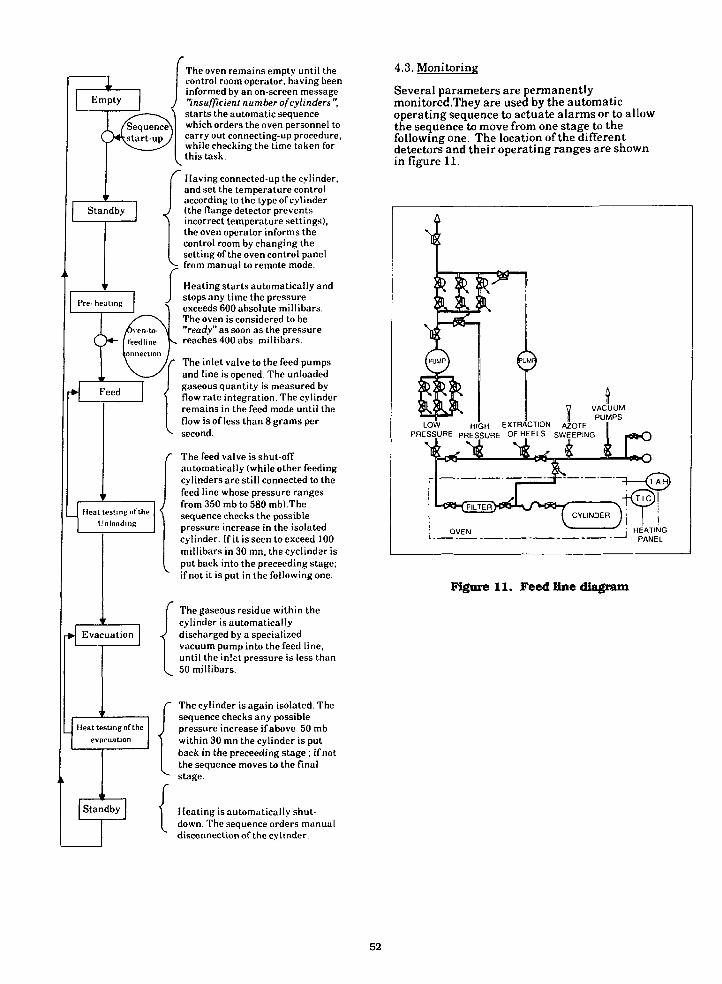
Empty
r Sequence^^start-up
Standby
Pre- heating
Heat testing of theUnloading
Evacuation
Heat testing of theevacuation
Standby
The oven remains empty until thecontrol room operator, having beeninformed by an on-screen message"insufficient number of cylinders ",starts the automatic sequencewhich orders the oven personnel tocarry out connecting-up procedure,while checking the time taken forthis task.
Having connected-up the cylinder,and set the temperature controlaccording to the type of cylinder(the flange detector preventsincorrect temperature settings),the oven operator informs thecontrol room by changing thesetting of the oven control panel
p: from manual to remote mode.
Heating starts automatically andJ stops any time the pressure
exceeds 600 absolute millibars.The oven is considered to be"ready" as soon as the pressure
. reaches 400 abs. millibars.
The inlet valve to the feed pumpsand line is opened. The unloadedgaseous quantity is measured byflow rate integration. The cylinderremains in the feed mode until theflow isoflessthan8gramspersecond.
The feed valve is shut-offautomatically (while other feedingcylinders are still connected to thefeed line whose pressure rangesfrom 350 mb to 580 mbl.Thesequence checks the possiblepressure increase in the isolatedcylinder. If it is seen to exceed 100millibars in 30 mn, the cyclindar isput back into the preceeding stage;if not it is put in the following one.
The gaseous residue within thecylinder is automaticallydischarged by a specializedvacuum pump into the feed line,until the inlet pressure is less than50 millibars.
The cylinder is again isolated. Thesequence checks any possiblepressure increase if above 50 mbwithin 30 mn the cylinder is putback in the preceeding stage ; if notthe sequence moves to the finalstage.
Heating is automatically shut-down. The sequence orders manualdisconnection of the cylinder.
4.3. Monitoring
Several parameters are permanentlymonitored .They are used by the automaticoperating sequence to actuate alarms or to allowthe sequence to move from one stage to thefollowing one. The location of the differentdetectors and their operating ranges are shownin figure 11.
LOW
0 VACUUM1 PUMPS
HIGH EXTRACTION AZOTEPRESSURE PRESSURE OF HEELS SWEEPING
Figure 11. Feed line diagram
52
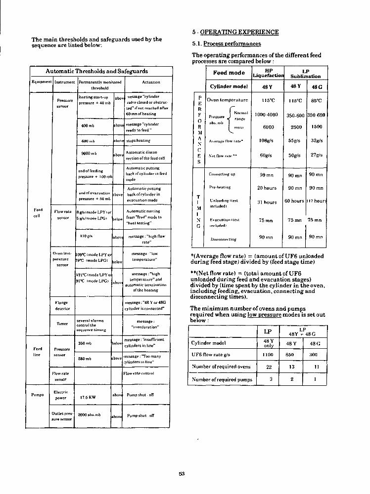
The main thresholds and safeguards used by thesequence are listed below:
Automatic Thresholds and Safeguards
Equtpnien
Feedcell
Feedline
Pumps
Instrumen
Pressuresensor
Flow ratesensor
Oven tern-lerature
sensor
Flangedetector
Timer
Pressuresensor
l̂ow ratesensor
Electricpower
)utlet pres-ure sensor
Permanently monitoredthreshold
heating start-uppressure + 40 mb
400 mb
600 mb
9000 mb
end of feeding
pressure + 100 m
end of evacuation
pressure + 50 mb
8g/s<modeLPYior
g/slmodeLPG>
110 g/s
OSTfmodeLPYtor
9*C (modeLPG)
21°C<modeLPYrO
I°C I modeLPG)
several a larmsontrol theequence timing
350 mb
580 mb
17.5 KW
2000abs.mb
abov
abov
abov
ibov
ibove
>elow
above
lelow
bovi
elow
>ove
bovi
>ove
Actuation
nessage "cylinder
/aJve closed or obstruc-
ted" if not reached after
60 mn of heating
message "cylinder
ready to feed "
stops heating
Automatic discon-
nection of the feed cell
Automatic putting
back of cylinder in feed
mode
Automatic putting
back of cylinder in
evacuation mode
Automatic moving
from "feed" mode to
"heat testing"
message: "high flow
rate"
message: "low
temperature"
message -."hightemperature" and
automatic terminationof the heating
message: "48 Y or 48G
cylinder is connected"
message:
"overduration"
message: 'insufficientcylinders in line"
nessage: "Too manyylinders in line"
•'tow rate control
Pump shut • off
Pump shut • off
5 - OPERATING EXPERIENCE
5.1. Process performances
The operating performances of the different feedprocesses are compared below:
pERFORMA\CES
TIM[NG
Feed mode
Cylinder model
Oven temperature
1 NormalPressure J r a n ( ; e
abs. mb 11 maxi
Average How rate*
Net flow rate **
Connectingup
Pre-heating
Unloading itestincluded)
Evacuation (testincluded)
Disconnecting
HPLiquefaction
48 Y
115°C
1000-4000
6000
108g/s
SOg/s
90 mn
20 hours
31 hours
75 mn
90 mn
LPSublimation
48 Y
1I5°C
350-600
2500
55g/s
50g/s
90 mn
90 mn
60 hours
75 mn
90 mn
48 G
85°C
350600
1500
32g/s
27g/s
90 mn
90 mn
17 hour!
75 mn
90 mn
*(Ayerage flow rate) = (amountofUF6 unloadedduring feed stage) divided by (feed stage time)
**(Net flow rate) = (total amount of UF6unloaded during feed and evacuation stages)divided by (time spent by the cylinder in the oven,including feeding, evacuation, connecting anddisconnecting times).
The minimum number of ovens and pumpsrequired when using low pressure modes is set outbelow:
Cylinder model
UF6 flow rate g/s
Number of required ovens
Number of required pumps
LP48 Yonly
1100
22
3
48Y +• 48 G
48 Y
650
13
2
48 G
300
11
1
53

Tests have shown that if the cylinder is isolated atany moment during unloading and the heatingshut off, the accumulated heat is insufficient toliquefy the remaining UF6 in LPG mode. With thetemperature control set to 85°C, the worst casesituation is that of a cylinder at the end ofunloading and with a low flow rate.With 150 Kg of UF6 remaining, 1500 mb would bereached only after 9 hours and this for a period of 2hours.
PumrumpsOne ope
1500
PRESSURE BUILD UPmb
140 kg
-___ 1200 kg
7B00kgT.—-—' • 9M0kg
1 2 3 4 5 6 7 8CYLINDER DISCONNECTING
HOURS
Figure 12. Incidental pressure build-up
Therefore, pressure build-up is sufficiently slow toallow either the reconnection of the cylinder whenfeeding restarts or the one-off evacuation of acylinder having a pressure which has built-up toohigh. In the LPY mode, with the same conditions,except an initial temperature control of 115°C,liquefaction would occur and the pressure wouldreach 2500 mb (to be compared with the 5000 mballowed by our specification in that case - see § 2).
A long trial period was necessary to adjust theautomatic sequence control parameters in order tomake the sequence capable of running from startto finish in any circumstances, and to bring thecylinder from connection to disconnection whileallowing its unloading and evacuation in asatisfactory way. End-of-unloading criteria wereparticularity delicate to adjust. There can be somedoubt concerning the residual amount of UF6within the cylinder, above all when the cylindertare is unknown.
5.2. Equipment
FiltersNo clogging-up of filters has been noticed, theonly stripping-down has been for regularinspections (every 3 years) required by the"Service des Mines" (national regulatory body).Cleaning and decontaminating of the filter arecarried out outside of the unit and present noparticular difficulties. The essential purpose ofthese filters was to prevent any non-volatileimpurities from entering the pressure sensors, thevalves and the vacuum pumps which aredownstream. In this regard, they have proved to beefficient.
)ne operation limit is to not exceed 110°C at thevacuum pump discharge in order to avoid thedecomposition of UF6 into UF4 or otherproducts.The lowering of pump oil temperature using athermostatic valve set to 68°C has meant areduction of 5°C in the temperature of thedischarge pipe casing. Since start-up, thenumber of operating hours for these pumps hadamounted to 78000 hours.By reducing the compression ratio and using anelectric power trip, the formation of depositswithin the core of the pump has been avoided.
Flow-rate measureThis is currently carried out by membranepressure-loss gauges (ECA sensor). We are infact installing thermic flow-rate sensors(SETARAM*) which provide better accuracy.
Leak detectionThis is carried out by means of miniictometers for pollution detection (MIP) whichwork by accumulating the UO2F2 resultingfrom the hydrolysis of UF6, on a filter placed ina detection chamber. Recent tests using ionicfume detectors have demonstrated that theselatter provide higher sensitivity.
5.3. Lessons learnt from incidents
Cylinder valve obtruction caused by crystallizedUF6 or by UO2F2, has occured several times :- Once there was a case of valve jamming butfinally the valve was opened and the flow-ratewas found to be normal.- In another case a valve was opened but therewas no resulting flow. The obstruction wasinside the needle seating of the valve. Measuredpressure build-up was abnormal after 30minutes heating and heating was immediatelyshut down.- In a third case, the flow was noticed to beextremely low after valve opening (obstructioncaused by porous U02F2). This case is the mostdelicate as it is necessary to interpret thedifference between the nominal flow curve andthe actual one in order to shut down as quicklyas possible if necessary to avoid an unknownpressure increase inside the cylinder.
6 - CONCLUSIONS
The feed process using sublimation has provedto be very flexible allowing flow rates of up to1100 g/s. All operating procedures areautomatically controlled except for theconnecting and disconnecting of cylinders whichare carried out manually.There have been no operating incidents fromthis automatic procedure .As we have seen, EURODIF'S GEORGES BESSEplant has the capability to feed up to 35000 tons ofUranium hexafluoride. Therefore, it is one of theworld leaders in enrichment capacities and willremain up to the beginning of the next century.
*SETARAM : Societe d'Etudes d'automatisation,de regulation et d'appareils de mesures.
54

SAFE HEATING OF 48G CYLINDERS CONTAINING UF6
Robert H. DyerSystems Safety Engineer
the pressure and temperature are increased abovethe triple point conditions, only liquid or gaswill exist.
OAK RIDGE OPERATIONS OFFICEUNITED STATES DEPARTMENT OF ENERGY
OAK RIDGE, TENNESSEE
ABSTRACT
The gaseous diffusion plants produce enricheduranium to be used as fuel in nuclear reactors.In doing so, large quantities of 0.2% U235 tailsare produced. This material is in the form ofsolid UF5 and is in long-term storage in 48Gcylinders at the three plants.
The 48G cylinders is designed and, is designatedin 0R0 651 Rev. 5, to be a low cost container "fortails storage only". Recently a need hasdeveloped to use some of these cylinders forshort-term storage of toll enrichment normal assayUFg feed and a program has developed to utilizethe tails in another process.
This report is intended to provide the basis fordeveloping safe procedures to heat the 48Gcylinders in steam-heated autoclaves to remove theUFg. The effect of the variables of cylindervolume, net weight of UF5, cold cylinder pressure,and autoclave temperature are considered andlimits on these variables are stated.
To support these conclusion, the characteristicsof UF6 are provided, the cylinder is described,and calculations of cylinders internal pressuresare presented.
UF6 CHARACTERISTICS
UF6 is a solid compound at room temperature, butcan be maintained in the gas phase undercontrolled temperature and pressure conditions.In Figure 1, the phase relationship of pure UFg isdepicted as a function of pressure, expressed inpsia, versus temperature in degrees Fahrenheit.The triple point, the only combination of pressureand temperature where all three phases existsimultaneously, exists at a pressure of 22 psiaand a temperature of 147°F. If either, or both,pressure and temperature are lower than thesevalues, the UF5 will be a solid and/or gas. When
VAPOR
I I I I I I80 100 120 140 160 180 200 220 240
TEMPERATURE (°F|
Figure I. Phase diagram of UF, .
UF5 can be handled safety in essentially the samemanner as any other corrosive and/or toxicchemical by employing procedures developed toaccommodate the characteristics of the material.Illustrated in Figure 2 is a sealed glass vialthat has been evacuated to remove the air,partially filled with liquid UFg, and allowed tocool. The illustraton is provided to help thereader visualize the conditions inside a UFgcylinder. The photograph was taken where theambient temperature was 100°F. It shows off-whitecolored solid UFg crystals surrounded by colorlecUFg gas. If a pressure gauge were connected tothe vial, it would indicate a pressure of 5 psia.There is only gaseous and solid UF5 in the tube.If the tube is heated, some of the crystals willdisappear as they sublime to the gas phase,causing an increase in pressure. Appropriateinstrumentation would indicate that the heatrequired to vaporize the solid UFg. the heat ofsublimation, is 58.2 BTU/lb. If the tube isheated to a temperature of 147°F, the pressurewill be 22 psia and drops of colorless liquid willappear. If heating is continued, the pressurewill remain at 22 psia until of the solid is
55

melted in a phase change, during which the heat offusion is absorbed by the solid. As heating ofthe vial continues, the heat causes a rise intemperature of the liquid and, as the temperatureincreases, the liquid vaporizes causing anincrease of pressure.
when the contents reach a temperature of 194°F,the cylinder will be completely full. Any furtherheating will cause the confined liquid tohydraulically deform and rupture the cylinder.
Figure 2. Glass Vial Containing UF6.
Exactly the same changes occur in all cylinderswhich contain UFg. Regardless of its isotopiccontent, pure UFg will follow the phase diagram.However, if a cylinder contains impurities in theform of traces of other gases, the pressureencountered will be higher by a factor that isdirectly related to the phase relationships of theimpurities. The most common impuritiesencountered are hydrogen fluoride (HF), Freon-114,and air. The presence of these impurities can bedetected by measuring the gas-phase pressure of anunheated cylinder and comparing it to the UF5phase diagram. This vacuum check at ambienttemperature is frequently referred to as a"cold-pressure check". Impurities can cause thepressure to be significantly higher than the vaporpressure of 5 psia at 100°F ambient temperature,but will be far below the design pressure ratingfor the cylinder. Because these impurities havehigher vapor pressures than UFg, they can beremoved by evacuating some of the gas contentsfrom the cold cylinder. This evacaution procedureis analagous to a cold distillation in which thehigh vapor pressure components of the mixture arevaporized first. This is commonly referred to as"cold burping". Some UFg is removed during thisprocess, but the quantity is in the order of a fewpounds per 10-ton or 14-ton cylinder. The burpgas is drawn off through cold traps designed tocollect the UFg and pass the impurities.
The important physical characteristic that must beconsidered when liquid UFg is placed incylinders, is the change in liquid density as afunction of temperature. Figure 3 shows thisrelationship. It is this factor which can createan overfilling if not properly taken into account.In the gaseous diffusion plant, cylinders arefilled with liquid UFg at a temperature of 160°F,with the density of the material being 224.5lb/ft^. To illustrate what could happen, considerthat a cylinder with an internal volume of 139 ft^is filled to 97 percent of its volume capacitywith liquid UFg at a temperature of 160°F. Thecylinder would accept 30,270 lbs. in this case.However, if this cylinder is then heated to sometemperature about 160°F, the 3 percent remainingfree volume or ullage will gradually decreasebecause at higher temperatures each pound ofliquid UFg occupies more volume. In this example,
200 210 220 2:
DENSITY. L8/FT3
Figure 3. Density of liquid UFg.
This is a well understood phenomenon, andhydraulic rupture is prevented by establishingcylinder fill limits based on the UFg density at250°F for all cylinders, except the 48G where235°F is the basis when filled with tails. In DOEowned facilities, cylinders are heated in auto-claves with a controlled steam pressure of approx-imately 8 psig to guarantee that he contents willnot exceed a temperature of 235°F. In addition totaking the maximum liquid temperature intoaccount, the quantity of UF5 is limited to assureat least a 3% ullage when the full cylinder is atits design temperature. This gas phase volume isnecessary to avoid the possibility of exceedingthe cylinder design pressure due to the presenceof high-vapor pressure containments. Adherence tothese safe heating conditions is assured by (1)publishing the cylinder fill limits, (2) requiringthe cylinder manufacturer to measure the cylindervolume by weighing it full of water and stampingthis water capacity on the cylinder namepli.e, (3)maintaining accurate scales to determine the netcontents of a cylinder, (4) operating thewithdrawal stations to yield high purity UFg (5)controlling the maximum steam heating pressure,and (6) utilizing the cold cylinder vapor pressuremeasurement to verify the amount of volatileimpurities present before heating the cylinders.
48G CYLINDER CHARACTERISTICS
In the past forty years, a family of different-size cylinders has been developed to safely con-tain UFg. These approved cylinders are describedin Report 0R0-651, Rev. 5, Uranium Hexafluoride:Handling Procedures and Container Descriptions andthe American National Standard for Packaging ofUranium Hexafluoride for Transport, ANSI,N14.1-1987. The 48G cylinder was designed to be aminimum cost, large-capacity container for long-term storage of tails assay UFg at the gaseousdiffusion plant.
56
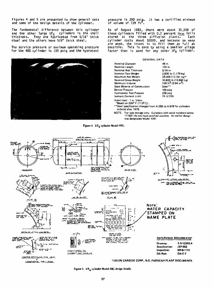
Figures 4 and 5 are presented to show general dataand some of the design details of the cylinder.
The fundamental difference between this cylinderand the other large UFs cylinders is the shellthickness. They are fabricated from 5/16" thicksteel and the others have 5/8" thick steel.
The service pressure or maximum operating pressurefor the 48G cylinder is 100 psig and the hydrotest
pressure is 200 psijj.of volume of 139 ft*.
It has a certified minimum
As of August 1983, there were about 15,500 ofthese cylinders filled with 0.2 percent U235 tailsstored at the three diffusion plants. Eachcylinder costs about $2000, and because so manyare used, the intent is to fill them as full aspossible. This is done by using a smaller ullagefactor than is used for any other UF6 cylinder.
GENERAL DATA
Nominal DiameterNominal LengthNominal Wall ThicknessNominal Tare WeightMaximum Net WeightNominal Gross WeightMinimum VolumeBasic Material of ConstructionService PressureHydrostatic Test PressureIsotopic Content Limit
Valve Used- 1-in. Valve.•Based on 235° F (113° C).
"Steel specification changed from A-285 to A-516 for cylindersordered after 1978.
NOTE: For tails storage only. Cylinders with serial numbers below111821 do not have certified volumes. An earlier designwas designated Model 'OM'.
48 in.146 in.5/16 in.2,6001b (1.179 kg)28,000(12.701 kg)*30,600 Ib (13,880 kg)139 f t3 (3.94 m3)Steel"100 psig200 psig1% U-235
Figure 4. UF6 cylinder Model 48G.
Note.'WATER CAPACITYSTAMPED ONNAME PLATE
REFERENCE DOCUMENTS'
Drawing: ES-12292 ASpecification: JSP-553Inspection: ME&I-11CQA nan: QA-E-7
•UNION CAR8IDE CORP.. N.D. PADUCAH PLANT DOCUMENTS.
Figure 5. UF6 cylinder Model 48G design details.
57

The 48G cylinder maximum fill limit is 28,000 lb.UFg. This is the quantity of tails assay UFgwhich when heated to 235°F will leave a 3 percentfree volume in a cylinder whose certified minimumvolume is 139 ft'. The contents of the ullage isassumed to be composed of UFg gas and a smallamount of air. The partial pressure of UFg gaswill be the vapor pressure for the temperature ofthe liquid UFg which has been put in the cylinder.
The partial pressure of air will be the result ofcompressing the initial quantity of air in theempty cylinder into the final ullage.
Each year the Paducah Gaseous Diffusion Plant hasthe responsibility to procure new 48G cylindersfor the three diffusion plants. Oifferentmanufacturers supply them, but since they are allbuilt to the same drawings and specifications,they are all nearly identical. One of theimportant features of the cylinder is itscertified minimum volume of 139 ft3; this is thevalue that determines the UFg fill limit.Beginning in 1972, the minimum volume for allcylinders above serial number 111821 has beencertified by weighing the cylinder full of 60°Fwater and stamping the water capacity weight onthe stainless steel cylinder nameplate. Becauseof the importance of this weight, the scale usedfor the determination is accurate to +0.1 percent.To assure that the scale maintains its accuracy,it is checked frequently with a check weight,which is a 48G cylinder full of water that hasbeen weighed on the Paducah uranium accountabilityscales that are accurate to +0.001 percent.
If a cylinder has a volume of exactly 139 ft9, itswater capacity at 60°F would be 8673 lb.
At the K-25 Plant a random check of 46 of the 48Gcylinders, made by three manufacturers over aperiod of 13 years, showed the mean water weightto be 8980 lbs. with a low of 8917 lb. and a highof 9041 lb. These weights correspond to anaverage volume of 143.9 ftJ, with a low of 142.9ft3 and a high of 144.9 ftJ. The sample includedboth new empty cylinders and ones that had beenfilled for years. "V-
CYLINDER PRESSUE CALCULATIONS - 235°F
The Normal Operating Temperature Limit for UFgautoclaves, specified in the Operational SafetyRequirements (OSR) for the three diffusion plantsand the Feed Material Production Center is 235°F.Therefore, the pressure developed when a fullcylinder is heated to 235°F needs to be examined.
Assume that a cylinder is stamped with a watercapacity of 8950 lb., contains 28,000 lb. UFg,and its cold pressure is 5 psia.
Ideal Gas Law:
Where:
p2v2
pl = cylinder cold pressurecold cylinder free volumecold cylinder temperature "Rankincylinder hot pressurehot cylinder free volumehot cylinder temperature °Rankin
P2 is the pressure of interest so the equationbecomes:
Po - P1 V1 T2
According to Dalton's Law the total pressureof a gas is equal to the sum of the partialpressures of the components, therefore, i f thecylinder has a cold pressue of 5 psia at 68°Fwhen the vapor pressure of UFg is 1.5 psia,then the pressure of the non-condensible gasis
Pj_ = 5 - 1.5 = 3.5 psia
Total volume of
cyl. = 8950 1bS water = 143.4 ft3
62.4 lb/ft3 water
Density of solid UFg at 68°F is 317.8 lbs/ft3,therefore
28'000 1b3 ^ . gs.! f t3 of so1id UF e 6 8 o F
317.8 lbs/ftJ
VI = 143.4 - 88.i = 55.3 ft3
Density of liquid UFg at 235°F is 207.1lbs/ft3, therefore
28,000 lbs U F 6 =
207.1 lb/ft3
V2 = 143.4 - 135.2 = 8.2 ft3
Tj = 460 + 68°F = 528°R
T 2 = 460 + 235°F = 695°R
Substituting these values in the equation:p, - (3.5H55.3H695)2 (528K8.2)
= 31.1 psia of air
= +79.0 psia vapor press of UFg & 235°F
110.1 psia total pressure in the cylinder
Similar calculations have been made for differentcylinder volumes and are shown in Figure 6. Notethat if the cold pressure is 5 psia, the pressurein the cylinder at 235°F is lower than thecylinder service pressure for water capacitiesgreater than 8870 lb. This would be a minimumacceptable water capacity to use as a guide forfeeding 48G cylinders containing 28,000 lbs ofUFg. However, considering the inaccuracies of thecalculation, the inaccuracies of the scales usedto determine the water capacity, and the desire tooperate slightly below the cylinder servicepressure, a water capacity of 8950 lb. should beset as the minimum acceptable.
58
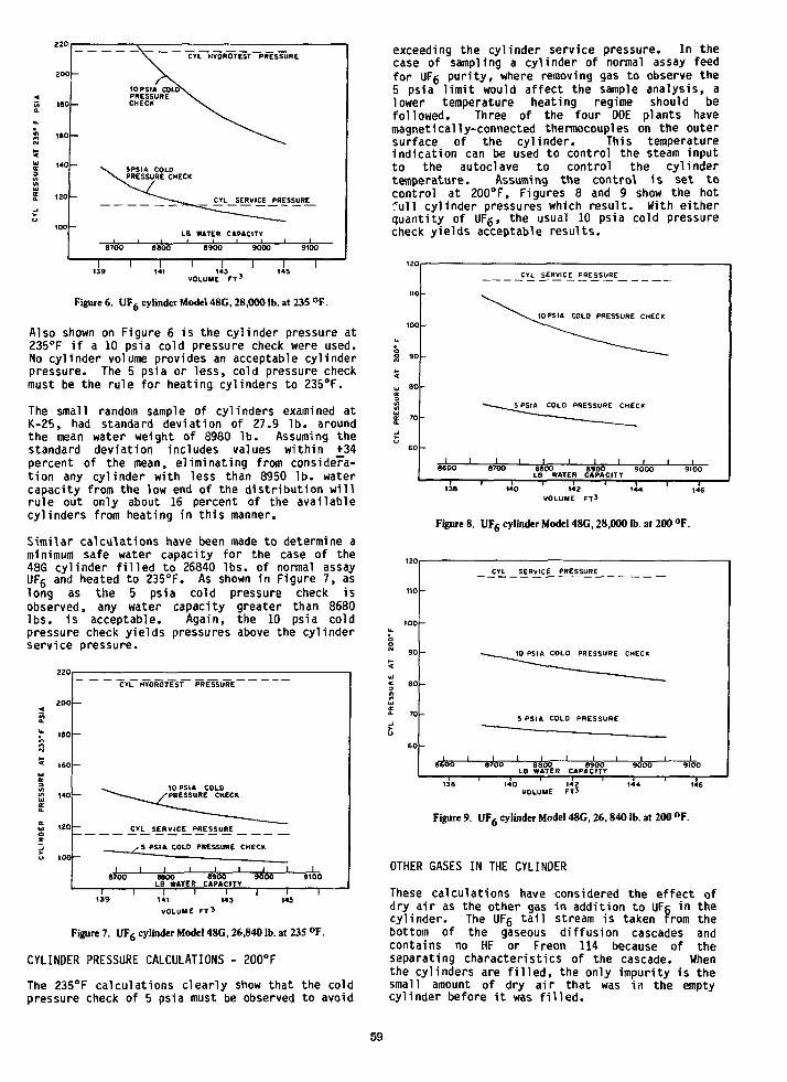
CVL KYOROTEST PRESSURE
CYL SERVICE PRESSURE
US WATER CAPACITY
139 141I 1 1 I
143 145VOLUME FT 3
Figure 6. UFfi cylinder Model 48C, 28,000 lb. at 235 °F.
Also shown on Figure 6 is the cylinder pressure at235°F if a 10 psia cold pressure check were used.No cylinder volume provides an acceptable cylinderpressure. The 5 psia or less, cold pressure checkmust be the rule for heating cylinders to 235°F.
The small random sample of cylinders examined atK-25, had standard deviation of 27.9 lb. aroundthe mean water weight of 8980 Ib. Assuming thestandard deviation includes values within +34percent of the mean, eliminating from considera-tion any cylinder with less than 8950 lb. watercapacity from the low end of the distribution willrule out only about 16 percent of the availablecylinders from heating in this manner.
Similar calculations have been made to determine aminimum safe water capacity for the case of the48G cylinder filled to 26840 lbs. of normal assayUF6 and heated to 235°F. As shown in Figure 7, aslong as the 5 psia cold pressure check isobserved, any water capacity greater than 8680lbs. is acceptable. Again, the 10 psia coldpressure check yields pressures above the cylinderservice pressure.
200
ISO
,40
120
100
—
-
—
CYL HYOROTEST PRESSURE
^ 10 PSIA COLO^ / - PRESSURE CHECK
CYL SERVICE PRESSURE
^ , 5 PSIA COLO PRESSURE CHECK
| 1 | 1 1 1 1 18700 8800 8900 9000
LB WATER CAPACITY
19100
VOLUME FT'
Figure 7. UFfi cylinder Model 48G, 26,840 lb. at 235 °F.
CYLINDER PRESSURE CALCULATIONS - 200°F
The 235°F calculations clearly show that the coldpressure check of 5 psia must be observed to avoid
exceeding the cylinder service pressure. In thecase of sampling a cylinder of normal assay feedfor UFg purity, where removing gas to observe the5 psia limit would affect the sample analysis, alower temperature heating regime should befollowed. Three of the four DOE plants havemagnetically-connected thermocouples on the outersurface of the cylinder. This temperatureindication can be used to control the steam inputto the autoclave to control the cylindertemperature. Assuming the control is set tocontrol at 200°F, Figures 8 and 9 show the hot•ful 1 cylinder pressures which result. With eitherquantity of UFg, the usual 10 psia cold pressurecheck yields acceptable results.
u, aocr3bJ
£ 7I
CYL SERVICE PRESSURE
10 PSIA COLD PRESSURE CHECK
140 142VOLUME FT 3
Figure 8. UFfi cylinder Model 48G, 28,000 lb. at 200 °F.
-
-
1 1S600
CYL
•
.
8700
SERVICE PRESSURE
10 PSIA COLO PRESSURE
" ^ —
5 PSIA COLO PRESSURE
.
1 1 1 1 18800 8900
LB WATER CAPACITY
CHECK
"
1 i9000 9tOO
140 142VOLUME FT3
Figure 9. UF6 cylinder Model 48G, 26,840 lb. at 200 °F.
OTHER GASES IN THE CYLINDER
These calculations have considered the effect ofdry air as the other gas in addition to UFc in thecylinder. The UFg tail stream is taken from thebottom of the gaseous diffusion cascades andcontains no HF or Freon 114 because of theseparating characteristics of the cascade. Whenthe cylinders are filled, the only impurity is thesmall amount of dry air that was in the emptycylinder before it was filled.
59
However, it is conceivable that a cylinder instorage could have its valve seat leak, permittingthe free volume to rise to atmospheric pressurewith wet air, thereby producing some HF from thereaction of water with UF5. The result of thiswas calculated in the following manner:
Assuming the 28,000 1b. of solid UFg to be at atemperature of 68°F with a density of 317.8Ib/ft3, there will be 55.3 ft3 of free volume inthe cylinder.
The vapor pressure of UFg at 68°F is 1.5 psia.Therefore, 14.7 psia - 1.5 psia = 13.2 psia =partial pressure of air in the ullage.
This is equivalent to
13.2 psia14.7 psia x 55.3 ftJ = 49.7 Standard Cubic
Feed (SCF) of Air
One pound of saturated air at 68°F occupies 13.613SCF. Thus
49.7 = 3.65 lbs of air would exist in thecylinder,
Assuming the leakage occurred when the air temper-ature was 100°F and the relative humidity was 100percent, there would be 0.043 lb . HgO/lb a i r .
3.65 x 0.043 = 0.157 lb . HoO available forreaction with UFg according to the followingequation.
molecular weights
352UF61.535 lb.
36+ 2H20
0.157 1b. 1
308U02F2
.343 1b.+
0
804HF.349 1b
The 0.349 1b. of HF produced by the reaction canbe expressed:
0.349 lb . HF20 Mol wt. HF 0.0175 mol HF
0.0175 x 359 (1b. molecular volume) = 6.26 SCF
This amount of HF in the 55.3 FT3 ullage of thecylinder is
if I scp = U.3% of the gas mixture
Since the t o t a l pressure in the ul lage i s 14.7ps ia , of which 11.3% is HF, then 1.66 psia is thepa r t i a l pressure of HF. The vapor pressure ofpure HF at 68°F is 14.9 psia so a l l the HF in theul lage w i l l stay in the gas phase and not condenseto l i q u i d . Therefore, when the cy l inder is heated
a f te r being evacuated to 5 psia leaving only 0.12lb of HF, the increasing pressure of th is smallquant i ty of HF gas w i l l not cause the f i n a lpressure to be any d i f f e ren t than i f the ul lagehad been f u l l of a i r only.
HYDRAULIC FORCES
Hydraulic forces created by expansion of l i q u i dUFg cannot rupture a 8950 1b. water capacitycy l inder containing 28000 l bs . of UF6 when i t isheated to 235°F in an autoclave. The design ofthe autoclave u t i l i z e s a steam-pressure con t ro l l e rto l i m i t the steam pressure to 8 psig (235°F), andcy l inder skin temperature monitors are i ns ta l l edt o automatical ly cut o f f the steam i f the cy l inderwall temperature exceeds 235°F. A cy l inder wi thvolume of 143.4 f t 3 , and f i l l e d with 28,000 l b .UF6, would have to be heated to 279°F (steampressure of 33 psig) to completely f i l l i t w i thl i q u i d UFg and es tab l ish the potent ia l fo rhydraul ic rupture.
CONCLUSIONS
Adhering to the fo l low ing provis ions w i l l assuresafe heating of 48G cy l i nde rs .
1 . No cy l inder wi th a ser ia l number lower than11821 should be heated.
2. No cy l inder with greater than 28,000 l b . ofUFg should be heated.
3. No cy l inder should be heated to 235°F wi th awater capacity of less than:
a. 8950 l b . when f i l l e d28,000 1b. UF6 or
to no more than
b. 8680 lb. when26,840 1b. UFg.
filled to no more than
The ullage of the cylinder should be evacuatedto 5 psia or less before heating to 235°F.
The steam pressure to the autoclave should notexceed 8 psig for 235°F service.
The cylinder skin temperature thermocouples inthe autoclave should be set to shut off thesteam at 235°F.
The cylinder internal pressure measuringinstruments should be set to shut off thesteam no higher than 114.7 psig. (100 psig)
When sampling a cylinder, where the coldpressure cannot be reduced to 5 psia, thecylinder skin temperature thermocouples shouldbe set to control the cylinder temperature at200°F by adjusting the steam flow.
60

UFg-RELEASE IN A GERMAN FUEL FABRICATION PLANT
- SEQUENCE AND CONSEQUENCES -
H. BayerReaktor-Brennelement Union
Hanau, F.R.G
T. GrillenbergerGesellschaft fur Reaktorsicherheit
Garching, F.R.G.
ABSTRACT
In April 1987 a UF- release occurred in theconversion facility of3 the Reaktor-BrennelementUnion at Hanau, F.R. Germany. The incidentsequence started with a small leakage at astuffing box of the main UF_ valve of an evapo-ration autoclave. The operators stopped thenormal evaporation process and closed the mainUF- valve and the UF- cylinder valve. Obviouslythe remotely driven DFg cylinder valve was notclosed totally and was not checked by hands. Soa release occurred out of the exhausting device.Due to the water in the evacuation pump a plugof UO-F. was built up in the exhausting linenear trie pump and then the pressure increaseduntil the flexible tube broke open. This majorrelease was stopped after some minutes by ope-rators wearing respirators. The released UF.remained totally within the building and neinjury to personal health was observed althoughthe whole floor and all components in thebuilding were covered with UO2F_. Details of theinstallations, the incident secfueTice, the radio-logical impact as well as the consequences, theimprovement in the technical equipment and theoperation manual are described.
PROCESS AND EQUIPMENT
In the fuel fabrication plant of the Reaktor-Brennelement Union (RBU) at Hanau F.R. Ger-many uranium dioxide powder is produced by theAUC-conversion process / 1 / . The gaseous UF.is lead into a aqueous fluid simultaneous witnCO- and NH,. The resulting ammonium uranylcarbonate (ATJC) is prepicipated and filteredand later on treated by thermal decompositionand reduction in a fluidized bed reactor(fig. 1).
For the evaporation of the low enriched uraniumhexafluoride, which is in 30" cylinders, steamheated autoclaves are used. The precipitatoris a slab vessel with a circulating loop. The
process gases are fed into the aqueous fluidin nozzles within the loop. The off gas of thevessel is lead to a jet scrubber and furtheron to a spray scrubber and the fitter system.
Off GasCleaning
Evaporator Precipitator Rotary- Filter
Fig. 1: AUC-Precipitation
61

The UF f i cylinder valve can be driven remotely.The pigtail within the autoclave consists ofstainless steel. The UFg line from the autoclaveto the precipitation vessel is electrically heated.The main closing valve for safety shut down islocated directly above the autoclave ( f ig . 2 ) .Between this valve and the controlling valve theexhausting device and the C O , flooding systemare connected, which are normally closed by apneumatic valve. After branching of exhaustingline and CO2-line there are hand valves. Nearthe T-piece ff pressure gauge is installed.
offgas tospray scrubber
f lineexhausting device
process lineto precipitator
1 [XX!—pneumaticvalves
remotedrive ofcylindervalve
control valve
main closing valve
UF6 Cylinder autoclave
Fig. 2: Evaporating Equipment
The exhausting device consists of a liquid sealpump with a fluid loop connected to the pool ofthe jet scrubber ( f ig . 3 ) . To protect the pumpagainst cavitation there is a vacuum breaking bypass. The exhausting line is partially con-structed with a flexible tube, since the plantwas in a back-fitting procedure concerning theexhausting equipment.
In normal operating conditions the vacuum systemis used to exhaust small UFg discharges es-pecially during cylinder changing. The CO_ gassystem is used for the leakage tests Beforeheating the UFg cylinders and for emptying thegaseous residues. For this purpose C O , is fedin the almost empty cylinder and it works as adelivery gas. All these operations in normalconditions are done according to a detailed checklist.
INCIDENT SEQUENCE
On April 27th 1987 at about 11 p.m. there was aheated and almost full cylinder in the auto-clave. The batch was started 15 minutes ago.
by pass
Fig. 3: Jet Scrubber and Exhausting Pump
A small leakage at the stuffing box of themain UFg closing valve appeared. The operatorsstopped the normal evaporation process andclosed the UF~ cylinder valve and the mainvalve. In order to repair the leaky valve theUF. process line had to be evacuated by theexhausting device with the liquid seal pump.Therefore the hand valve was opened and theunder pressure was checked at the pressuregauge. Now the two pneumatic valves wereopened. Unexpectedly a pressure increase wasobserved. When the operators were looking forthe reason of this pressure rise, anevacuation alarm came and they had to leavethe building. The UF. released into the hall outof the bypass line of the pump. Since thescrubber is in another room, the operators atthe evaporator could not see the release andcould not realize the connection between their
manipulation and the alarm. The facility remainedin this condition with valves opened.
Obviously the remotely driven UF~ cylinder valvewas not closed totally and was not checked byhands. The UFg streamed through the ex-hausting line to the liquid seal pump into thescrubber pool. Due to the water in the pumpplugs of UO-Fg were built up, first in the smallbypass and "then in the exhausting tube. Theseplugs of about 30 to 50 cm length were foundtwo days later during the search for theincident reasons and sequence.
62
Due to the plug the pressure increased in theline until the flexible tube broke open. Thissecond major release occured 3 minutes afterthe alarm near the door between two conversionhalls. The time was recorded by the UF_ warningdevices and little later by the fire detectors atthe opposite end of the hall. About 10 minutesafter alarm two operators wearing full protectionand respirators entered the hall and closed allvalves by hand and stopped the release. Theyfound the halls totally filled with UO_F2 fog.The distance of sight was only 10 cm.
After the incident the floor and the installa-tions of the process halls were found allcovered with a UOpF- layer. Investigating theequipment for the Incident reasons about 1 kguranium was found in the UO?F? plugs and inUF_ plugs within the pigtail ana fne valves. Thecylinder valve and all valves were found closed,but the solid UFfi found in the normally heatedpart of the UF- fine is a hint that the cylindervalve was still open during cool down of thecylinder. The amount of released UF_, estimatedby weighing the cooled cylinder, was about50 kg. Of this amount about 10 kg were ab-sorbed in the scrubber.
RADIOLOGICAL CONSEQUENCES
Due to the early evacuation alarm caused by thefirst small release at the exhausting pump thewhole shift had left the hall before the majorrelease occurred.
One hour after the incident the ventilating systemwas closed because of activity alarm in the offgas. The monitor in the air outlet duct showedan increase to 15900 Bq a-counts per minute.The first evaluation of the survey filtersresulted in a activity of 5.9 Bq/m3, so thereleased activity due to the incident wasestimated to 7.95 MBq. In comparison the limitfor gaseous effluents is 22.2 MBq per month.The release to the environment was clearlybelow the permitted value.
Within the building the first measurements of theactivity in the air were conducted at 7 a.m. inthe morning of the next day. The air in the con-version hall had 30 Bq/m3 a-radiation, in theadjacent rooms only 0.4 Bq/m3 respectively0.72 Bq/m3 were observed.
In the following hours the main filter elements ofthe air cleaning center were replaced. Theventilation system returned to operation at3:30 in the afternoon. The access to theprocess rooms without respirators or masks wasreleased by the protection survey at 6 p.m.,since only 0.3 Bq/m3 in the air were measured.After that the staff began to decontaminate thehall and the installations.
The operating personel in the chemical processwho had left the hall after the evacuationalarm was checked for radioprotection andmedica! reasons. All of the 23 persons hadno symptoms of HF etching. Nevertheless theirurine probes were investigated to estimatethe uranium incorporation. All of them were
far below the permissible limit. The next dayall members of the night shift were investi-gated once more by the plant physician and nohealth injury could be observed.
TECHNICAL CONSEQUENCES
Several lessons learned from the mishap con-cerning the technical installations and theoperations have to be mentioned. There are someimprovements in the equipment:
- The bypass iine of the liquid seal pump hasbeen removed .So the vacuum breaking functionto avoid cavitation is suppressed, but thatis tolerable in normal operating conditions.
- The planned equipment for exhausting withheated pipes of stainless steel and pumpsrelated to each autoclave has been installedimmediately.
- The control of the main closing valve at theautoclave and the pneumatic valve at theexhausting line is improved so that even inthe case of repair the emergency shut downfunctions will guarantee the safe closure.
- The control of the remote drive for the UFgcylinder valve is improved so that the im-perfect closure of the valve is more unlikely.
Also in the operating manual some details areimproved:
- The closure of the cylinder valve has to bechecked by hands and by a tightness proofwith over and under pressure.
- The repair of the main closing valve at theautoclave or of leaky components within theautoclave will not be conducted untill thecylinder has been cooled down.
- The autoclave will not be opened for inter-ventions while a heated cylinder is inside,excepted for a quicker cool down without anymanipulations.
- The check list for the normal operation withchanging of UFg cylinders is enhanced so thatthe condition of interventions during eva-poration is included.
CONCLUSIONS AND SAFETY PRINCIPLES
The technical equipment and the operating pro-cedures are suitable for the safe handling andprocessing of UF. and for plant maintainance.The deficiencies wriich gave the possibility of themishap are clearly recognized and the lessonslearned lead to some improvements especially inthe operators manual and know how.
The principles of the german safety requirements/ 2 /- autoclaves as a second containment- building or separate rooms as third con-
tainmentfor the inclusion of UFfi during handling inliquid phase or as gas witr? overpressure securedthat no radiological impact to the environmentoccurred. Even in repair conditions the require-ment of a second containment for handling liquidUF. will be respected consequently in thefuttire.
63

The use of liquid seal pumps connected with ascrubber pool for the vacuum generation in theexhausting device seems to f i t emergency require-ments, since the self sealing behaviour by U O , ^is an advantage if a large amount of UFg is re-leased into the device.
To enhance the safety of UFg evaporation it isconsidered to improve the autoclaves with aclosed loop for direct steam heating, with apossibility of wall cooling and with separatedevaporator rooms. So the multiple containmentconcept as it is suggested in the safetyrequirements can be performed in all normaland abnormal conditions.
REFERENCES
/ 1 / Sondermann T . ,Die Qualitatskontrolle als Hilfsmittelzur Festlegung der Produktionsparameterbei der Herstellung von LWR-Brennstoffen,Journal of Nuclear Materials106 (1982) p. 4 5 - 5 2
/ 2 / Der Bundesminister des Inneren (BMI),Sicherheitsanforderungen fur die Herstellungvon Leichtwasserreaktor-Brennelementen mitniedrig angereichertem Uran, GRS-Report,RS-AGK 5-510321, Juni 1383
/ 3 / Grillenberger T . ,Stand der Sicherheitsvorkehrungen gegenUFg-Freisetzungen, GRS-Report, Marz 1988
64
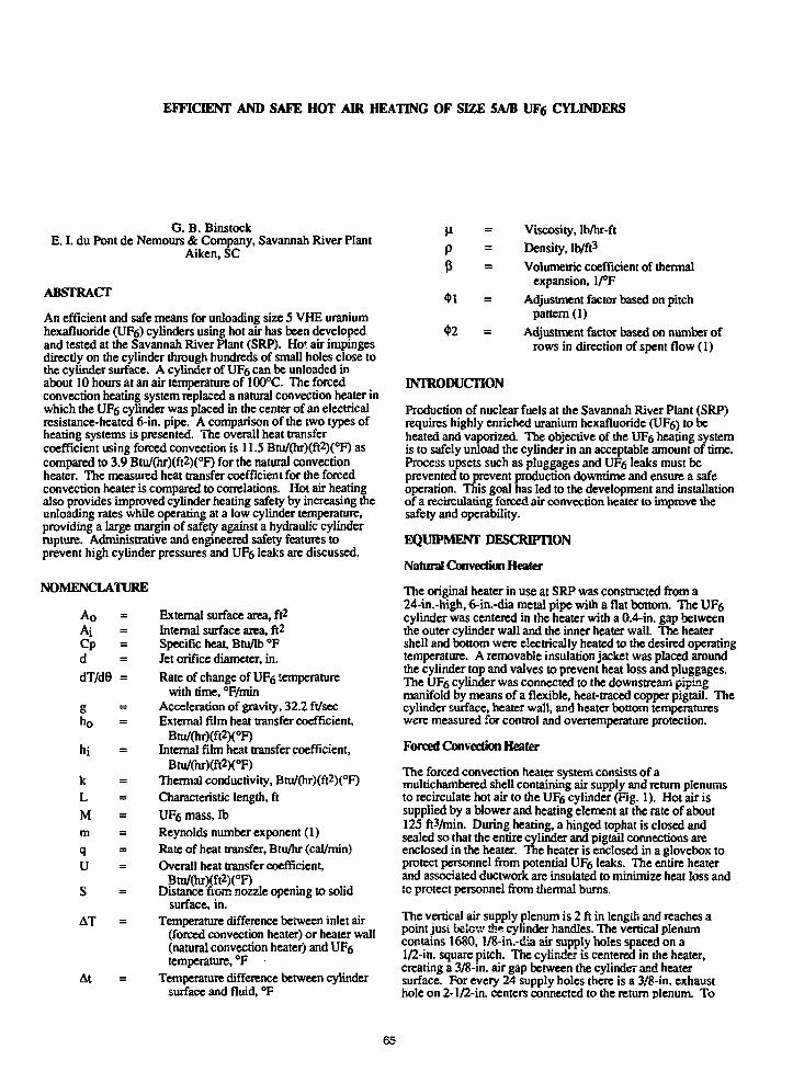
EFFICIENT AND SAFE HOT AIR HEATING OF SIZE 5A/B UF6 CYLINDERS
G. B. BinstockE. I. du Pont de Nemours & Company, Savannah River Plant
Aiken, SC
ABSTRACT
An efficient and safe means for unloading size 5 VHE uraniumhexafluoride (UFg) cylinders using hot air has been developedand tested at the Savannah River Plant (SRP). Hot air impingesdirectly on the cylinder through hundreds of small holes close tothe cylinder surface. A cylinder of UFe can be unloaded inabout 10 hours at an air temperature of 100°C. The forcedconvection heating system replaced a natural convection heater inwhich the UFg cylinder was placed in the center of an electricalresistance-heated 6-in. pipe. A comparison of the two types ofheating systems is presented. The overall heat transfercoefficient using forced convection is 11.5 Btu/(hr)(ft2)(oF) ascompared to 3.9 Btu/(hr)(ft2)(°F) for the natural convectionheater. The measured heat transfer coefficient for the forcedconvection heater is compared to correlations. Hot air heatingalso provides improved cylinder heating safety by increasing theunloading rates while operating at a low cylinder temperature,providing a large margin of safely against a hydraulic cylinderrupture. Administrative and engineered safety features toprevent high cylinder pressures and UF6 leaks are discussed.
NOMENCLATURE
A o =AiCp =ddT/d8 =
Eh o =
hi
kLMm =
q
us
AT
At
External surface area, ft2
Internal surface area, ft2
Specific heat, Btu/lb °FJet orifice diameter, in.
Rate of change of UF6 temperaturewith time, °F/min
Acceleration of gravity, 32.2 ft/secExternal film heat transfer coefficient,
Btu/(hr)(ft2)(°F)Internal film heat transfer coefficient,
Btu/(hr)(ft2)(°F)Thermal conductivity, Btu/(hr)(ft2)(°F)
Characteristic length, ft
UF6 mass, lb
Reynolds number exponent (1)Rate of heat transfer, Btu/hr (cal/min)Overall heat transfer coefficient.
Btu/(hr)j;ft2)(oF)Distance worn nozzle opening to solid
surface, in.Temperature difference between inlet air
(forced convection heater) or heater wall(natural convection heater) and UFetemperature, °F
Temperature difference between cylindersurface and fluid, °F
p
p
Viscosity, lb/hr-ft
Density, lb/ft3
Volumetric coefficient of thermalexpansion, 1/°F
Adjustment factor based on pitchpattern (1)
Adjustment factor based on number ofrows in direction of spent flow (1)
INTRODUCTION
Production of nuclear fuels at the Savannah River Plant (SRP)requires highly enriched uranium hexafluoride (UFg) to beheated and vaporized. The objective of the UF6 heating systemis to safely unload the cylinder in an acceptable amount of time.Process upsets such as pluggages and UFe leaks must beprevented to prevent production downtime and ensure a safeoperation. This goal has led to the development and installationof a recirculating forced air convection heater to improve thesafety and operability.
EQUIPMENT DESCRIPTION
Natural Convection Heater
The original heater in use at SRP was constructed from a24-in.-high, 6-in.-dia metal pipe with a flat bottom. The UFgcylinder was centered in the heater with a 0.4-in. gap betweenthe outer cylinder wall and the inner heater wall. The heatershell and bottom were electrically heated to the desired operatingtemperature. A removable insulation jacket was placed aroundthe cylinder top and valves to prevent heat loss and pluggages.The UF6 cylinder was connected to the downstream pipingmanifold by means of a flexible, heat-traced copper pigtail. Thecylinder surface, heater wall, and heater bottom temperatureswere measured for control and ovcrtemperature protection.
Forced Convection Heater
The forced convection heater system consists of amultichambercd shell containing air supply and return plenumsto recirculate hot air to the UF6 cylinder (Fig. 1). Hot air issupplied by a blower and heating element at the rate of about125 ftVmin. During heating, a hinged tophat is closed andsealed so that the entire cylinder and pigtail connections areenclosed in the heater. The heater is enclosed in a glovebox toprotect personnel from potential UF6 leaks. The entire heaterand associated ductwork are insulated to minimize heat loss andto protect personnel from thermal bums.
The vertical air supply plenum is 2 ft in length and reaches apoint just below th* cylinder handles. The vertical plenumcontains 1680, !/8-in.-dia air supply holes spaced on a1/2-in. square pitch. The cylinder is centered in the heater,creating a 3/8-in. air gap between the cylinder and heatersurface. For every 24 supply holes there is a 3/8-in. exhausthole on 2-1/2-in. centers connected to the return plenum. To
65
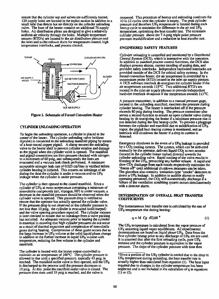
ensure that the cylinder top and valves are sufficiently heated,120 supply holes are located in the tophat section in addition to asmall tube that directs hot air directly on the cylinder unloadingvalve. The base of the heater contains an additional 76 supplyholes. Air distribution plates are designed to give a relativelyuniform air velocity through the holes. Multiple temperaturesensors (RTD's) are located in the air distribution plenum andthe inlet and outlet exhaust ducts for temperature control, hightemperature interlocks, and process control.
TOPHAT COOLER AIR RETURN
BLOWER
HOT AIR SUPPLY
Figure 1. Schematic of Forced Convection Heater
CYLINDER UNLOADING OPERATION
To begin the unloading operation, a cylinder is placed in thecenter of the heater. The cylinder unloading valve (withoutdiptube) is connected to the unloading manifold piping by meansof a heat-traced copper pigtail. A clamp secures the unloadingvalve to the heater shell to prevent cylinder rotation and damageto the pigtail when the cylinder valve is opened. The manifoldand pigtail connections are then pressure-checked with nitrogento a minimum of 60 psig, and subsequently the lines areevacuated and a vacuum leak check performed. A minimumacceptable nitrogen leak rate of 0.025 cm3/sec is verified beforecylinder heating is initiated. This ensures no inleakage of airduring the time the cylinder is under a vacuum and no UF6leakage when the cylinder is under pressure.
The cylinder is then opened to the closed manifold. Since acylinder of UFg at room temperature containing a minimum ofnonvolatile compounds (air, nitrogen, HF) is under vacuum, adecrease in the manifold pressure should be observed when thecylinder valve is opened. This pressure drop is verified toensure that the operator has actually opened the cylinder valve.If the pressure drop is not observed or the cylinder pressure isnot less than 10 psig, the cylinder is evacuated (cold-burped)and the valve opening procedure repeated. The cylinder vacuumis later checked to ensure that no inleakage from a valve packinghas occurred. An adequate vacuum prior to heating the cylinderis essential in ensuring that high cylinder pressures do not occuras a result of thermal expansion and compression of nonvolatilegases during heating. Compression of these gases occurs due tothe large increase in UFg volume at the solid-liquid phase changein addition to the further increase in liquid UF6 volume withtemperature, reducing the free volume in the cylinder andmanifold.
The cylinder is heated with the heater output controlled tomaintain an air temperature of 100°C. The cylinder pressure isallowed to rise until a specified pressure, typically 45 psig, isreached. The manifold outlet valve is then opened, and the UF6is discharged to the process until the pressure decreases to10 psig. At this point the manifold outlet valve is closed. Thepressure then rises until 35 psig is reached, and the valve is
reopened. This procedure of heatup and unloading continues for10 to 12 cycles until the cylinder is empty. The peak cylinderpressure and therefore UFg temperature is limited during eachheatup cycle to maximize the difference in the air and UF6temperature, optimizing the heat transfer rate. The minimumcylinder pressure above the 7.4-psig triple point pressureprevents rcsolidification and a reduction in heat transfer rate.
ENGINEERED SAFETY FEATURES
Cylinder unloading is controlled and monitored by a DistributedControl System (DCS), which is interactive with the operators.In addition to standard process control functions, the DCS alsodisplays process alarms, current trending of analog data, andprovides safety interlocks. Independent hardwired interlocks areprovided outside of the DCS for critical safety systems. In theforced convection heater, the air temperature is controlled by atemperature probe (RTD) located in the inlet air supply plenum.A DCS software interlock de-energizes the cylinder heater if theair temperature exceeds 115°C. Two additional RTD's arelocated in the inlet air supply plenum to provide independenthardwire interlock shutdown if the temperature exceeds 115°C.
A pressure transmitter, in addition to a manual pressure gage,located in the unloading manifold, monitors the pressure duringcylinder heating. The heater is interlocked off if the pressureexceeds 80 psig during heating. The pressure transmitter alsoserves a second function to ensure an open cylinder valve duringheating by de-energizing the heater if a minimum pressure rise isnot detected during the first heatup cycle. To prevent a pluggagebetween the cylinder and manifold due to solidification of UFgvapor, the pigtail heat-tracing current is monitored, and aninterlock will shutdown the heater if a drop in current isdetected.
Emergency shutdown in the event of a UFg leakage is providedby a CO2 cooling system. The system, which can be activatedmanually by the operator, delivers liquid CO2 to two nozzles(located in the cylinder heater tophat) directed towards thecylinder unloading valve. Rapid cooling of the valve results infreezing of the UFg, preventing any further release. A rapid andslow CO2 discharge from each nozzle respectively maintains the"freeze off' until additional shutdown measures can be taken.The glovebox also contains ionization-type "smoke" detectors todetect a UFg leakage. In addition to audible alarms to notifyoperating personnel, the CO2 will automatically discharge if afailure of the ventilation scrubbing system occurs simultaneouslywith a detector alarm.
DETERMINATION OF OVERALL HEAT TRANSFERCOEFFICIENTS
The instantaneous heat transfer rate is calculated by the rate ofUF<5 temperature rise during heating:
q - M Cp dT/d8 * (1)
The UFg temperature is calculated from the vapor pressure ofUFg assuming liquid-vapor equilibrium. All experimentaldeterminations are based on liquid phase UFg. Data from thefirst cylinder heatup prior to any discharge of UFg are not used.It is assumed that after the first unloading cycle, pure UF5remains and the cylinder pressure is equivalent to the vaporpressure. The slope of the cylinder pressure with time then
*Since a portion of the UFg cylinder is cooled due to the drop inUF6 temperature during unloading, the heat transfer rate isactually higher than calculated from equation (1). The heat inputrequired due to changes in the cylinder temperature has beenneglected and is not included in the calculation of q in equations(1) or (2).
66

provides the instantaneous rate of temperature rise. The mass ofUFg in the cylinder at any given time is calculated from theamount of UF6 removed from the cylinder based on downstreamprocessing conditions after each of the unloading cyclespreviously described. The heat transfer rate during each heatupcycle is then determined at a point when the UFg temperaturereached 75°C (16.3 psig).
The overall heat transfer coefficient, U, is determined where therate of heat transfer is
q = U AT. (2)
The area, Ao, has been defined as the external cylinder surfacearea in contact with the liquid UFg, determined from the mass(volume) of UF6 remaining in the cylinder. The external surfacearea and the instantaneous heat transfer rates were thendetermined during each heatup cycle. The slope of the heattransfer rate divided by the temperature difference versus theexternal surface area is then the desired overall heat transfercoefficient.
RESULTS AND DISCUSSION
Production data for the two heating systems were analyzed todetermine the heat transfer rate for the natural convection versusforced convection heater. Cylinder pressure is shown as afunction of heatup time for the two systems in Fig. 2 for the firsttwo heatup and unloading cycles. A direct comparison can bemade of the time required to liquify all of the UF6 in thecylinder. The time when the UF6 begins to melt at the triplepoint is evidenced by a decrease in the rate of pressure riseduring the first heatup cycle. The triple point (64°C) is reachedin 35 minutes with the forced convection "versus 140 minuteswith natural convection. The time when all of the UFg hasmelted is indicated by an increase in the rate of pressure rise,which occurred at 90 minutes for the forced convection and350 minutes for natural convection. The total time required tomelt the UF6 is then 55 minutes and 210 minutes, respectively.The ratio of 3.8 is then an indication of the improvement in theheat transfer rate for the forced convection heater. This is only arough estimate, and no determination of the overall heat transfercoefficient was attempted using these data.
The pressure continues to increase during the time required toliquify the UF6 indicating two phases and a nonuniformtemperature distribution in the cylinder. The average UFgtemperature and the cylinder surface area in contact with the UF6are difficult to predict with any accuracy. The porous nature ofthe solid UF6, difficulty in predicting the percentage of solid andliquid during fusion, and the large decrease in density at thephase change prevent an accurate determination of the overallheat transfer coefficient
To provide a more accurate comparison and actual values for theoverall heat transfer coefficient, the method described previouslywas employed. The data in Table 1 are a summary of heattransfer data during each heatup cycle at a point when the UFgtemperature was calculated to be 75°C. The temperaturedifference is therefore 25"C between the cylinder contents andthe heating medium. In Fig. 3, the heat transfer rate as afunction of surface area is presented with the slope equal to theoverall heat transfer coefficient. For the forced convectionheater a value of U of 11.5 Btu/(hr)(ft2)(°F) was calculatedversus 3.9 Btu/(hr)(ft2)(°F) with the original natural convectionheater, for a factor of three improvement
The increase in the heat transfer is explained by the differentprincipal mechanisms for the external heat transfer coefficient forthe two heating systems. In the natural convection heater, heattransfer from the heater to cylinder is across a small air gap.Natural convection occurs due to the difference in temperaturebetween the heater and cylinder surface. In addition to naturalconvection, the contribution to the outside heat transfercoefficient from radiative heat transfer is expected to be on thesame order of magnitude as that from natural convection.
In the recirculating hot air heater, the relatively high air velocitycreated by the small impingement holes changes the mechanismfor heat transfer to forced convection. The convective heattransfer coefficient between a solid surface and an array of gasjets normal to it may be found from equation (3), Ref. (1). Allproperties are at the orifice outlet The quantities m, $1, and *2are graphically presented:
h = *14.2 12 k N R e m (S/d) O-^ 1 Npr°- 3 3 3 /d , (3)
Table 1. Heat Transfer Rate during Each Heatup Cyde
0 Forced Convection— Resistance Heater
0 200 400 600 800
Tlnw, mln
Figure 2. Rate of Pressure Rise during Heating
1000
HeatupNumber
dT/dt<S>75°C
°F/min
UF6Mass
lb
Natural Convection Heater
12345
1.071.131.171.21
53.234.723.716.59.0
Forced Convection Heater
12345678
3.013.914.183.154.014.014.03
53.638.327.320.715.211.47.95.2
ExternalSurface Area
ft2
1.831.310.970.62
2.001.481.170.910.740.570.44
Heat TransferRate. O
Btu/hr
30818315586
908841682377362250165
67
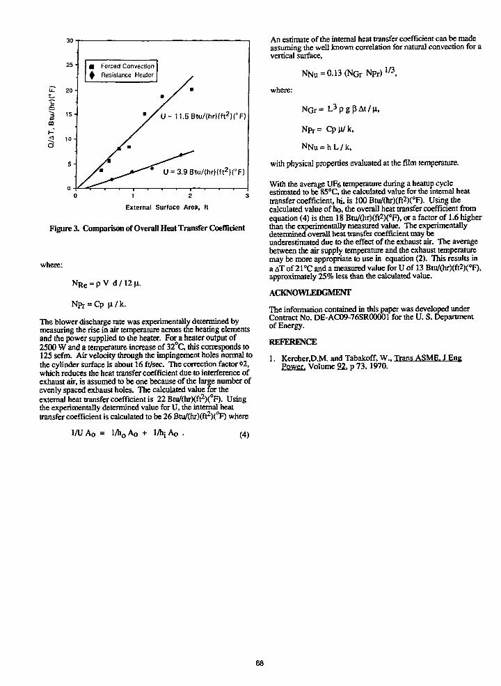
30
25
U. 20 -
• Forced Convection4 Resistance Healer
U=11.5Btu/{hr)(ft2)(°F)
U = 3.9Btu/(hr)(ft2)CF)
1 2
External Surface Area, It
Figure 3. Comparison of Overall Heat Transfer Coefficient
where:
N R e = p V d / 1 2 n .
The blower discharge rate was experimentally determined bymeasuring the rise in air temperature across the heating elementsand the power supplied to the heater. For a heater output of2500 W and a temperature increase of 32°C, this corresponds to125 scfm. Air velocity through the impingement holes normal tothe cylinder surface is about 16 ft/sec. The correction factor «2,which reduces the heat transfer coefficient due to interference ofexhaust air, is assumed to be one because of the large number ofevenly spaced exhaust holes. The calculated value for theexternal heat transfer coefficient is 22 Btu/(hr)(ft2)(°F). Usingthe experimentally determined value for U, the internal heattransfer coefficient is calculated to be 26 Btu/(hr)(ft2)(°F) where
NGr= L 3 p g ( J A t / n ,
An estimate of the internal heat transfer coefficient can be madeassuming the well known correlation for natural convection for avertical surface,
where:
= Cpji/k.
= h L / k ,
with physical properties evaluated at the film temperature.
With the average UF6 temperature during a heatup cycleestimated to be 85°C, the calculated value for the internal heattransfer coefficient, hi, is 100 Btu/(hr)(ft2)(°F). Using thecalculated value of ho, the overall heat transfer coefficient fromequation (4) is then 18 Btu/(hr)(ft2)(°F), or a factor of 1.6 higherthan the experimentally measured value. The experimentallydetermined overall heat transfer coefficient may beunderestimated due to the effect of the exhaust air. The averagebetween the air supply temperature and the exhaust temperaturemay be more appropriate to use in equation (2). This results ina AT of 21 °C and a measured value for U of 13 Btu/(hr)(ft2)(°F),approximately 25% less than the calculated value.
ACKNOWLEDGMENT
The information contained in this paper was developed underContract No. DE-AC09-76SR00001 for the U. S. Departmentof Energy.
REFERENCE
1. Kercher.D.M. and Tabakoff, W., Trans ASME. J EngPower. Volume 22, p 73, 1970.
1/U AQ = l/h0 AQ + I/hi (4)
68
SAFETY AND SECURITY IMPROVEMENTS IN THE PGDP UFe SUBSAMPLING LABORATORY
S. K. Hoishouser and D. R. JollyMartin Marietta Energy Systems, Inc.
Paducah Gaseous Diffusion PlantPaducah, Kentucky USA
ABSTRACT
To provide additional assurance that nuclearmaterials are being handled safely and securely,the UFC Subsampiing Laboratory at the PaducahGaseous Diffusion Plant has made some majorchanges in operating methods. Three systems havebeen redesigned to Improve safety, and a nearreal-time Inventory system has been devised tomaximize the security of nuclear materials while1n the lab. To handle the return of excessUF6 from samples back to the cascade, a newdumping system was designed and Installed by plantpersonnel which eliminates the use of theopen-flame torch as a heat source 1n theoperation. The new system uses a combination ofself-limiting heat tape and temperature controlswith high temperature alarms. Similarly, thesubsampHng manifold used to take small aliquotsfor the various analytical measurements from thelarger bulk sample cylinders has been replacedwith an electrically heated, temperature-controlled, and alarmed system. Again, theopen-flame torch was removed. Preparation of thecylinders for reuse Involves fluorination topassivate the Inner surfaces. The new manifoldsystem designed for this procedure 1s automated toeliminate the need for manual valving of fluorineInto the system. Finally, a program has beenwritten and Installed on the lab computer sampletracking system enabling lab personnel to know thelocation and status of all 2S sample cylinders.The near real-time Inventory requires only a fewminutes of operator time each day to updatecylinder status changes and makes It possible tocomplete an Inventory of all sample cylinders Inless than forty-five minutes. These Improvements,with existing procedures and policies, assure thesafe and secure handling of nuclear materials bylab personnel at the Paducah Gaseous DiffusionPlant (PGDP).
Pnpond by tm Patucali Oooaow DMuMon Pton.Pattah. K>Mud« 42001, eftntti by UAflTHHAAETTA ENEBOY SYSTEMS. MCOflPOIUTED.k» * » U.S. DEPARTMENT OF ENEDOY. vM*Contract No. DE-AC0M4OfttUC0.
raucrW hm bM« atfhond by aoMndor el * • U J . OowmnM undar Contact No.DE-AC0S-S4OR21400. AccwMngly. Ilw U.S.
• o n * to •ytthlt of npMuoa « • pubhhW torn ofM> ombuttn. or Oow olhon to do o>. lor U.S.
INTRODUCTION
The PGDP UF» Subsampiing Laboratory 1s responsiblefor: 1) subsampHng UF, from 2S cylinders Intosmaller containers suitable for various laboratoryanalyses, 2) dumping the excess UF6 from 2Scylinders Into 12A cylinders for refeeding to thecascade, and 3) cleaning and fluorinating the 2Scylinders for reuse. Even though this typelaboratory handles relatively small quantities ofUF6 as compared to cascade operations, there aremany of the same safety concerns. To provideadditional assurance that safety guidelines arebeing met, Improvements have been made in each ofthe above mentioned functions. Due to theIncreased emphasis on security of small quantitiesof nuclear materials, a computer sample cylindertracking system and additional physical controlshave been added.
SUBSAMPLING
Subsamples for the various analytical measurementsare taken from bulk sample containers (usually 2Scylinders). An open-flame torch had previouslybeen used to supply the heat necessary tosubsample UF,. Because this type of torch 1s anuncontrolled heat source, an alternate method ofheating was sought. Fiameless subsampUng wasdemonstrated by Hall, Hedge, and Reid through theuse of controlled heating tape and a cartridgeheater.v1) Using the same concepts, a system wasconfigured by Subsampling personnel which fit thesubsample tube and space requirements needed.Safety features of the system Include:
1. Self-limiting heat tape and cartridge heaters
2. Manifold fabricated and Inspected to UF,pigtail specifications
3. Temperature control
4. Audible and visible alarms
5. Automatic system shutdown
6. Redundancy 1n power control
DUMPING
The 2S cylinder simples which are no longer neededare dumped Into 12A cylinders which can be refed

to the cascade. This system, like the subsamplingsystem requires a heat source. The open-flametorch has been replaced with canister heaters andheat tape. Safety features Include:
1. Self-limiting heat tape
2. Eleven monitored points with audible hightemperature alarm
3. Dual ventilation system
FLUORINATION
After the 2S cylinders have been cleaned, they arepassivated with fluorine before they are returnedto service. An automated fluorination system hasbeen installed which allows the laboratory analystto perform this operation within an enclosed hood.Safety features include:
1. Automated operation
2. Pump-down interval alarms
3. Self-limiting heat tape
4. Remote operation of fluorine valves
5. Fluorine flow sensor and automatic shut-off
CYLINDER TRACKING SYSTEM
With increased emphasis on nuclear materialphysical security, an efficient means ofinventorying 2S sample cylinders was needed. Acomputer tracking system which uses existinglaboratory computer equipment was implemented forthis purpose. The following steps summarize theprogram operation:
1. All 2S cylinders are entered in the program bytheir cylinder number.
2. The cylinder number is coded to giveadditional Information about the cylinderstatus (e.g., material type, control, etc.).
3. The location or person responsible is entered.
4. A dated entry Is made 1n one of fourcategories:
READY FOR USESENT TO C-360IN USEDUMPED
5. The program Is updated daily, or as needed, ascylinder status changes.
6. A status listing compiles all of theinformation, including a container count.
This near real-time Inventory allows an inventoryof all 2S cylinders 1n the plant to be made andverified in 30 to 45 minutes. Dally Input to thesystem usually takes less than five minutes--muchshorter than other physical means of tracking thecylinders would be. Also, the program 1s writtento be flexible so that additional information,such as hydrotest dates or other cylinder types,can be included.
SUMMARY
Recent changes 1n the Subsampling Laboratoryoperations provide additional assurance that thehandling of UF6 is performed in a safe manner.The use of a computer cylinder tracking systemprovides an expedient near real-time inventorywhich is flexible for future changes.
REFERENCES
1. H. J. Hall, W. D. Hedge, and D. D. Reid,Uranium Hexafluoride Subsampling System,Martin Marietta Energy Systems, Oak RidgeGaseous Diffusion Plant, Oak Ridge, Tennessee;July 1985 (K/PS1096).
70
USE OF TAMPER INDICATING DEVICES (TID) ON UF6 CYLINDERS
J. W. GrishamMartin Marietta Energy Systems, Inc.
Paducah Gaseous Diffusion PlantPaducah, Kentucky
ABSTRACT
Tamper Indicating Devices (TID) have been used atthe Paducah Gaseous Diffusion Plant (PGDP) for anumber of years to Indicate the authenticity andto verify the Integrity of UF6 cylinder shipments.
All shipments Involving any nuclear materialcontainer, Including shipments of empty cylinders,are sealed with an accountable TID. Anunviolated TID permits verification of thecontents of the container. Conversely, a violatedseal is an Indication of possible tampering.
Several alternative designs were developed andtested. A cost effective TID was designed andImplemented that achieved high quality and metobjectives of Indication of tampering of the valveand valve part.
TID CHARACTERISTICS
A. Frangible - Seals are easily broken and arenot Intended as deterrents to an adversarywilling to use force but will Identify Iftampering has occurred.
B. Nonreversible - Once a seal 1s broken, it 1sdifficult to reassemble without leaving signsof tampering.
C. Identifiable - Seal must be distinguished byunique Identification characteristics, suchas serial numbers to remain traceablethroughout the system.
HISTORY OF THE USE OF TIDs AT PGDP
A number of different type TIDs have been used atthe Paducah plant over the years. Leadnonnunbered seals on the valve protector was thefirst TID used (Figure 1). Plastic bags with theseals on the Inside of the bag were tested for a
Pnpm) br *» P a t e * Qauow M M o n Plani,Padua*. Kmudir 42001. apmrM by MART*!MARETTA ENERGY SYSTEMS, INCORPORATED,for «w U.S. DEPARTMENT OF ENERQY, UM«Conma No. DEACKWOR21400.
Tt» tUbmM n w u c * * tm W > autand by •eonraaer ol»» US. Gowmmm undar Cams No.DE-AC0S-MOR21400. Aecordkiglr. Iha U.S.
k m » pubM at namdint to puHhMd km «ttk conMbuaon. or atar Mtan lo do *D. Mr U.S.
period of time (Figure 2). A reinforced bag withfiberglass strands woven 1n the bag was alsotested. This bag could not be torn and would showsigns of tampering If a wrench was used to unscrewthe valve. During the testing of this bag, 1t wasdiscovered that when the temperature was below tendegrees fahrenheit, the glued seam would pullapart (Figure 3).
Various other plastic bags were tested using wireseals (Figure 4). The main problem found with theplastic bags was the difficulty 1n threading thewire through the six prepunched holes andattaching the seal under adverse winterconditions.
During the development efforts for a new design,the following objectives were considered: highquality, low cost, virtually Impossible to accessany part of the valve body without detection, andability to install the TID under adverse winterconditions with gloves on.
The first TID tested was made from a section ofschedule 40 PVC pipe with a solvent welded PCVcap on one end. This TID version was discardeddue to the high cost of the material and labor tofabricate the TID (Figure 5).
The TID now being used at PGDP 1s a one-piece,seamless, tapered polypropylene plastic cover(Figure 6) attached to the cylinder valve with ametal pin and numbered seal (Figure 7).
Nuclear Material Control 2nd Accountability(NMC&A) must be combined with TID usage. Allshipment and receipt documentation ofUF, cylinders must contain the TID number.
All full and e-spty UF, cylinders being shipped areinspected to verify tfcat the TID Is properlyapplied and the TID number Is on the nuclearmaterials tally-out sheets and bill of lading.
This prototype design is proposed forIndustry-wide use. The TIDs must be accepted byall and somewhat consistent in design for the TIDsystem to work.
71
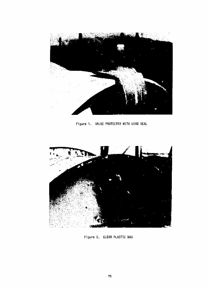
Figure 1. VALVE PROTECTER WITH LEAD SEAL
Figure 2. CLEAR PLASTIC BAG
72
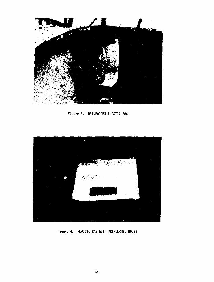
Figure 3. REINFORCED PLASTIC BAG
Figure 4. PLASTIC BAG WITH PREPUNCHED HOLES
73

Figure 5. PVC PIPE AND CAP
Figure 6. ONE PIECE SEAMLESS TAPERED PLASTIC COVER
Figure 7. LOCKING PIN AND SEAL
74
DEVELOPMENT OF A 20-TON-CAPACTTY LOAD-CELL-BASEDWEIGHING SYSTEM FOR IAEA FIELD USE1
J. N. Cooley, Oak Ridge Gaseous Diffusion Plant'T. J. Huxford, Oak Ridge National Laboratory 2
Oak Ridge, Tennessee 37831
ABSTRACT
A 20-ton-capacity Load-Cell-Based Weighing System(LCBWS) is being developed to provide the Inter-national Atomic Energy Agency (IAEA) with a port-able means of verifying the masses of 10- and 14-tonUF6 cylinders at UF6-bulk-handling facilities sub-ject to IAEA safeguards inspections* The system isbeing designed to meet IAEA objectives for portabil-ity and accuracy as well as to meet facility opera-ting safety conditions. During the developmenteffort, system design requirements were established,and a comprehensive survey of commercially avail-able weighing equipment against these requirementswas conducted. Detailed equipment specificationsfor 20 load cells from 13 manufacturers, for 5digital crane scales from 3 manufacturers, and for 7digital weight indicators from 5 manufacturers werecompared. The results of the survey favored a con-figuration based on a custom-designed load cellintegrated with a commercially available digitalweight indicator. Safety certification of thesystem by an internationally recognized verifica-tion authority is also recommended. Comparisoncriteria and their effect on the LCBWS designrequirements are discussed, and the status of theproject is reported.
INTRODUCTION
For the application of International Atomic EnergyAgency (IAEA) safeguards at uranium enrichment andfuel fabrication plants subject to IAEA inspection,the IAEA requires an independent means of verifyingthe masses of UF6 cylinders. Several portable 5-ton-capacity load-cell weighing systems have beendeveloped with the capability of weighing a 2.5-tonUF6 cylinder. These weighing systems have been inroutine use by the IAEA. To provide the IAEA with ameans of verifying the masses of 10- and 14-ton UF6cylinders at UF6-bulk-handling facilities, a 20-ton-capacity Load-Cell-Based Weighing System (LCBWS) isbeing developed. The system Is being designed tomeet IAEA objectives for portability and accuracyas well as to meet facility operating safety re-quirements. Funding for this equipment developmentis being provided by the U.S. Program for TechnicalAssistance to IAEA Safeguards (POTAS) under TaskA.137.
BACKGROUND
A prototype 20-ton-capacity LCBWS was developedjointly by Brookhaven National Laboratory and OakRidge Gaseous Diffusion Plant (ORGDP) (1). Theprototype system was configured as two parallelbranches, each of which was comprised of one11.4-ton-capacity ioad cell, two flexures, and
associated connecting hardware. The electronics ofthe system consisted of two digital load-cell indi-cators, one standardizer, and two digital tempera-ture indicators connected to resistance temperaturedetectors. The electronics of the LCBWS was inte-grated with a computer control system programmed(1) to guide an IAEA inspector through the LCBWSweighing procedure, (2) to prompt the electronicinstruments for the data, (3) to correct all fieldreadings to calibrated standards, and (4) to calcu-late the mass of a given UF6 cylinder. In-housetests of the prototype system indicated overallaccuracies of ±3 kg or better.
The prototype 20-ton-capacity LCBWS was field-testedby the IAEA at the Eldorado Resources, Ltd., facil-ity in Port Hope, Ontario, in September 1986 (2).The test involved repeated weighings of one 14-tonUF6 cylinder with different LCBWS configurations(e.g., with and without flexures, with and withoutcomputer interface). System accuracy and measure-ment repeatability demonstrated by the LCBWS wereexcellent. Cylinder weights as determined by theLCBWS computer system were within 0.05% of thefacility scale weight; cylinder weights from thedirect indicator readings were within 0.10% of thefacility scale weight. Measurement results wereunaffected by the removal of the flexures from theload-cell branches. To make the LCBWS a morerugged and portable system for routine IAEA fielduse, several modifications to the prototype systemwere suggested by the IAEA participants includingremoval of the flexures, removal of the temperatureIndicators, replacement of the two load-cell indi-cators with a single summing unit, battery opera-tion, and elimination of the computer controlsystem.
SAFETY CONCERNS
Another issue that was raised during the field testof the prototype LCBWS was the operational safetyof the system. At the time of the field test, theIAEA was experiencing difficulties in using their5-ton-capacity load-cell system in European facili-ties. The 5-ton system was certified for 1.5 timesits rated load. The British requested that theIAEA test each individual component of the systemto two times its rated load prior to its acceptabil-ity for use. The Germans requested a similarcertification criteria.
submitted manuscript has been authored by acontractor of the U.S. Government under ContractNo. DE-AC05-840R21400. Accordingly, the U.S. Govern-ment retains a nonexclusive, royalty-free licenseto publish or reproduce the published form of thiscontribution, or allow others to do so, for U.S.Government purposes.
2Operated by Martin Marietta Energy Systems, Inc.,under Contract No. DE-AC05-840R21400 with the U.S.Department of Energy.
75
Upon Investigation, it was discovered that no uni-form set of international standards for structuralsafety factors exists that applies to mechanicallifting hardware. The applicable American NationalStandards Institute, Inc., standard [i.e., ANSIN14.6-1978, "American National Standard for SpecialLifting Devices for Shipping Containers Weighing10,000 Pounds (4500 kg) or More for NuclearMaterials"] requires that all components of struc-tural appliances used to lift nuclear materialsweighing 10,000 lb or more be designed to have asafety factor of 5 relative to the ultimate strengthof the components. For purposes of sizing com-ponents, deadweight loads are the sum of thecylinder weight and any lifting hardware that willbe acting on the weighing system. Deadweight loadsshould be increased by an additional factor to con-servatively account for the inertia effects ofraising the cylinders with cranes and forklifts orbump loads induced by transporting cylinders withthe weighing system attached.
MODIFIED LCBWS DESIGN SPECIFICATIONS
Since their initial purchase, the load cells of theprototype 20-ton-capacity LCBWS have been downratedby the manufacturer from a safety factor of 5 to asafety factor of 3; this necessitated the replace-ment of the system load cells. Based on the systemmodifications identified during the IAEA field testof the prototype LCBWS and the inclusion of theANSI N14.6 safety requirements, new design require-ments for a modified 20-ton-capacity LCBWS wereprepared. The new configuration will be designedto meet IAEA technical objectives for accuracy andportability as well as to meet facility operatingsafety conditions. In addition, the system is to beconfigured with as many commercially available com-ponents as possible to minimize development timeand field maintenance. The expected accuracyachievable with the system is better than +0.1% ofthe weight being measured. The critical componentsof the system will be transportable by one person.To provide flexibility in interfacing with facilitylifting equipment, the weighing system will havethe capability for single- or double-branch con-figuration. The system will meet or exceed thesafety standards at any UF6-bulk-handling facilitywhere its use is anticipated. Safety certificationof the modified system by an internationallyrecognized verification authority is recommended.
EQUIPMENT SURVEY
Upon recommendation from the International Safe-guards Project Office (ISPO), a comprehensive surveyof commercially available load cells and digitalweight indicators for the 20-ton-capacity LCBWSwas conducted. Five commercially available cranescales were also Included for comparison. Detailedequipment specifications for 25 load cells from 15manufacturers, for 5 digital crane scales from 3manufacturers, and for 7 digital weight indicatorsfrom 5 manufacturers were compared. Comparisoncriteria for the weighing equipment included ulti-mate load factor, safe overload factor, rated out-put, accuracy, load cell weight, configuration,cost, and availability. Comparison criteria forthe digital weight indicators Included inter-changeability, count resolution, integral standard-Izer feature, weight, cost, and availability.
WEIGHING EQUIPMENT COMPARISON
Table 1 summarizes the specification ranges for the5 crane scales and 25 load cells compared in thesurvey. The load cells are grouped into three dif-ferent configuration categories based on shape:barrel, flat disc, and tension link (Figure 1).The barrel-type load cell is the most common typerepresenting 15 of the 25 cells surveyed. Disc-type and tension link load cells are evenly repre-sented at five cells each.
In selecting load cells and crane scales for com-parison, a maximum lifting load of 20 tons wasassumed. By sizing an individual load cell toaccommodate the largest lifting load anticipatedfor the LCBWS, the weighing system can be con-figured as a single-branch or double-branch system.An additional assumption was a system ultimate loadfactor of 7o5. (The system ultimate load factor isdefined as the ratio of the weighing device'sstructural failure load to 40,000 lb.) The 7.5ultimate load factor is based on the ANSI N14.6-1978 standard with a dynamic load factor of 1.5 toaccount for Inertia effects. (Because safety fac-tor requirements at foreign nuclear-material-handling facilities are unknown, the largest dynamicload factor requirement found in the industry, thatof the Portsmouth Gaseous Diffusion Plant, waschosen as a conservative figure.) When the staticand dynamic loads are combined, an overall systemultimate load factor of 7.5 results. The ratedcapacity of the commercial load cells and cranescales being compared ranged from 50,000 to 200,000lb because of the different ultimate load factorsused by the various manufacturers in designingtheir weighing devices. (Ultimate load factor isdefined as the maximum load as a factor of ratedcapacity that can be applied without producing astructural failure.) The standard manufacturer'sultimate load factor for crane scales is 5; load-cell ultimate load factors ranged from 2 to 5. Bymultiplying the manufacturer's ultimate load factorof a device by its rated capacity and then dividingby the maximum system lifting load of 40,000 lb, asystem ultimate load factor could be calculated.
As an indication of equipment ruggedness, safeoverload factors were compared. Ranging from 1.5to 2.0 for the crane scales and from 1-5 to 3.0 forthe load cells, the manufacturer's safe overloadfactor is defined as the maximum load as a factorof rated capacity that can be applied withoutcausing permanent damage to the weighing device.
The larger the electrical signal produced by a loadcell, the more sensitive the cell will be forsmall weight differences. The algebraic differencebetween the electrical signal produced by theload cell at Its rated capacity and at no load,expressed in terras of mV/V, Is known as the manu-facturer's rated output. To meet safety specifi-cations, many of the load cells being compared areoversized. Thus the signal output for these over-sized load cells in the expected operating range ofthe LCBWS (I.e., 4500 to 34,000 lb, correspondingto the nominal tare weight of a 10-ton cylinder andthe nominal gross weight of a full 14-ton cylinder)is substantially less than the cell's rated output.To compare the sensitivity of the various loadcells, signal outputs at 40,000 lb were calculated.
76
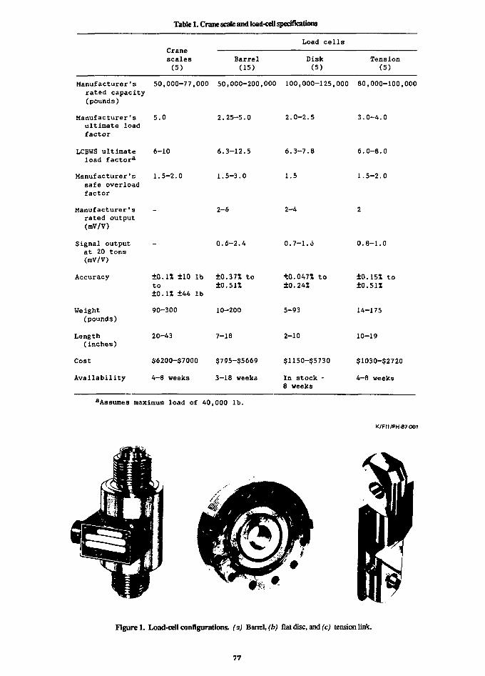
Table 1. Crane scale and load-cell specifications
Load cellsCranescales(5)
Barrel(15)
Disk(5)
Tension(5)
Manufacturer's 50,000-77,000 50,000-200,000 100,000-125,000 80,000-100,000rated capacity(pounds)
Manufacturer's 5.0ultimate loadfactor
LCBWS ultimate 6-10load factora
Manufacturer's 1.5-2.0safe overloadfactor
2.25-5.0
6.3-12.5
1.5-3.0
2.0-2.5
6.3-7.8
1.5
3.0-4.0
6.0-8.0
1.5-2.0
Manufacturer'srated output(mV/V)
Signal outputat 20 tons(mV/V)
Accuracy
Weight(pounds)
Length(inches)
Cost
Availability
-
+0.11 ±10 lbto+0.1S +44 1b
90-300
20-43
$6200-$7000
4-8 weeks
2-6
0.6-2.4
+O.37Z to±0.51%
10-200
7-18
$795-$5669
3-18 weeks
2-4
0.7-1.6
+0.047* to+0.24Z
5-93
2-10
$1150-$5730
In stock -8 weeks
2
0.8-1.0
±0.15% to±0.51%
14-175
10-19
$1030-$2720
4—8 weeks
aAssumes maximum load of 40,000 lb.
K/FII/PH-87-O01
Figure 1. Load-cell configurations, (a) Barrel, (h) flat disc, and (c) tension link.
77

The accuracy of a load cell is defined in terms ofnonlinearity, hysteresis, and repeatability. Theload-cell accuracy ratings listed in Table 1 arebased on the root mean square sum of these perfor-mance factors and are intended for use as a rela-tive comparison figure only. The accuracy ratingsfor the crane scales are actual equipment specifi-cations.
The weight and length listings in Table 1 refer topounds and inches of the minimum lifting deviceconfiguration that could be transported. Cranescales ranged from 90 to 300 lb and from 20 to40 in. Nondetachable swivel hooks and eye nuts onseveral models account for the figures in the upperend of each range. Weight varies substantially foreach type of load cell. Both the barrel-type anddisc—type load cells require separate attachmentssuch as eye bolts, hooks, or shackles to interfacethem with a lifting device such as a crane or fork-lift (Figure 2). These attachments add approxi-mately 60 lb to the reference weight and 10 in. tothe reference length of both types of cells. Thetension link load cells are configured with holesin their end plates for direct interface withlifting equipment.
K/FII/PH-87-002
TONGUESHACKLE
YOKESHACKLE
EYEBOLT
SWIVELHOOK
Figure 2. Sample load-cell interface aUachments.
The cost entries in the table are based on themanufacturer's suggested retail cost for a singleunit. The prices listed for the crane scalesinclude the end hooks. The reference costs for theload cells do not include any attachments. Areference price for a pair of tongue shackles forthe barrel- and disc-type load cells is approxi-mately $1000.
Availability refers to the time from receipt oforder required for delivery. Because of the largerated capacity of the weighing devices being con-sidered, the majority of the vendors do not havethe devices in stock ready for delivery. Inspeaking with representatives of the various load-cell manufacturers while checking availability,many vendors offered to custom-design a load cellto meet the 20-ton-capacity LCBWS design require-ments specifically. The cost and delivery time fora custom load cell was not substantially higher orlonger than catalog-listed load cells.
INDICATOR EQLIPMENT COMPARISON
Seven digital weight indicators were compared foruse in the LCBWS. All seven instruments weredesigned specifically for use in conjunction withload cells in weighing applications; therefore, allthe instruments considered have common featuressuch as push-button zero and motion detection.Table 2 summarizes additional design features forthese weight indicators. The instruments aregrouped into two different classes: Type I con-sists of microprocessor-based devices capable ofin-field calibration; Type II involves simplerdigital readout devices requiring laboratorycalibration and matching of load cells and cableswith the indicator. Two of the seven instrumentsfit into the first category; hence, design specifi-cations are listed for both devices. Instrumentcapabilities considered important for LCBWS appli-cation are interchangeability, accuracy, and anintegral standard!ler feature.
The interchangeability feature implies that theinstrument can be easily recalibrated in the fieldfor any load-cell and cable combination. Constant,multiplicative correction factors for local gravityand buoyancy can be easily input from the frontpanel. Without this capability, end-to-end cali-bration of the load cell, the cable, and the weightindicator are required.
The accuracy achievable with a given Instrument canbe quantitatively estimated by the specificationsof the instrument's voltage/frequency converter.For the indicators surveyed, two distinct classesof instruments were apparent (i.e., <20,000 countand 200,000 count). This specification can beinterpreted as an expected accuracy of ±4.0 lb forthe 20,000-count device and ±0.4 lb for the200,000-count Instrument. Clearly, If the ±0.4-lb-class instrument is used, Instrument accuracy canbe neglected when considering the overall LCBWSaccuracy. The cost associated with this betterresolution is nominally two to four times the costof the lower accuracy Instrument.
Table 2. Digital weight indicator specifications
TypeProgrammable Count Integral Battery Weightfront panel resolution standardizer option (pounds) Cost
Avail-ability
Type I (2)
Type II (5)
Yes
No
200,000
10,000-20,000
Yes
No
No
NoYes
(4)(1)
8 and
4—10
20 $3800$5400
$850-$2000
and In
In
stock
stock
78
The Integral standardizer feature provides an in-field check of Instrument accuracy by simulatingthe output of a load cell through a precisionresistor network and provides a feedback into theInstrument microprocessor for automatic meter driftcompensation in the readout. Load-cell systemsusing a weight Indicator without this featurerequire a separate standardizer in addition tomanual interpolation of data.
Only one of the seven weight indicators has a manu-facturer's supplied battery power option. The 8-lbmicroprocessor-based indicator Is comparable inweight to the Type II digital readouts. The 20-lbweight Indicator has an Integral printer feature.All of the instruments surveyed are stocked by thevendors for immediate delivery.
RECOMMENDATIONS
Based on the equipment surveyed for the LCBWS,three different system configurations are possible:(1) a production crane scale, (2) a production loadcell in conjunction with a production weight Indi-cator, and (3) a custom load cell in conjunctionwith a production weight Indicator. Option 3 wasrecommended as the base configuration for the20-ton-capacity LCBWS. While a weighing systembased on a commercially available digital cranescale has the advantages of being self-contained aswell as battery operated, the system is very heavy(i.e., >75 lb) and has a limited accuracy capa-bility (i.e., no better than ±44 lb). Having nointerchangeable parts, a crane scale is sensitiveto singlepoint failure in the field. A weighingsystem based on a load cell In conjunction with aweight Indicator has the advantages of being veryportable, accurate, and versatile. Because of thelow weights of the individual components (i.e.,load cell <20 lb, Indicator <10 lb), the system iseasily transportable. Field maintenance is feasiblewith spare parts. Cost of the system is comparableto a crane scale; however, because of the capabilityfor component replacement, maintenance costs shouldbe less. Readily achievable system accuracies ofbetter than ±0.1 J! will meet the current IAEA objec-tives for attributes measurements as well as futureaccuracy goals for variable measurements.
The recommended equipment for the modified 20-ton-capacity LCBWS includes a custom-designed load cellIn conjunction with a digital weight indicatorhaving an Integral standardizer. Although thereare catalog-listed load cells that meet the designrequirements, a custom load cell manufactured tooptimized design specifications can be lighter andmore accurate. Cost and availability for a custom-designed load cell do not differ substantially fromthose quoted for the production units. The digitalweight indicator with an integral standardizer per-mits the indicator to be used with any load cellfor which calibration data is available; end-to-end calibration of the system is not required.Certification of the 20-tor.-capaclty LCBWS in con-formity with various national safety standards by atechnical surveillance authority is also recom-mended .
PROJECT STATUSThe load-cell equipment survey was reviewed withboth ISPO and the IAEA in February 1987. Both con-curred with the recommendation for a custom-designedload cell; however, a battery-powered -eight indi-cator was preferred over the recommended weightindicator that featured an integral standardizer.Requests for bids on a custom-designed cell weresent to 14 load-cell vendors. The design specifi-cations for the load cell included (1) a 40,000-lbcapacity, (2) a weight of less than 40 lb, (3) a 2-to 3-mV/V output at 40,000 lb, (4) a safe overloadfactor of at least 1.5, (5) an ultimate overloadcapacity of 7.5, (6) an accuracy of better than0.1%, and (7) a capability of meeting the ANSIN14.6-1978 standard. Following receipt and reviewof the vendor responses, the plan was to place anorder for two identical cells and two battery-powered digital weight indicators. Assembly of the20-ton-capacity LCBWS and in-house field tests ofthe system were then scheduled.
In March 1987 the IAEA decided to assemble a new5-ton-capacity load-cell system instead of tryingto upgrade its current system by use of a heavysafety yoke. An order was placed for a large quan-tity of German—made 5-ton-capacity tension linkload cells and battery-powered digital weight indi-cators. In addition, three 20-ton-capacity tensionlink load-cell systems were ordered from the samemanufacturer. The IAEA then arranged for a Germansurveillance authority to work with the load-cellmanufacturer to certify the 5- and 20-ton load-cellsystems in conformity with various national safetystandards. In April 1987 ISPO notified MartinMarietta Energy Systems, Inc., that POTAS TaskA. 137 was officially on hold status pending aresponse from the IAEA on the status and operationof its new 20-ton-capacity load-cell systems. InDecember 1987 the material to be used by the manu-facturer for fabricating the load cells wasrejected by the certification authority after itfailed an impact test. In January 1988 the newmaterial passed all the required tests, and fabri-cation began. The current projection for deliveryof the certified and calibrated German load—cellsystems to the IAEA is April 1988. An offer hasbeen made to the IAEA to field-test the 20-ton-capacity LCBWS at the ORGDP.
REFERENCES
1. Kane, W. R. and McAuley, W. A., "A Load-Cell-Based Weighing System for Weighing 9.!- and 12.7-Tonne UFg Cylinders," J. Inst. flucl. Hater". Manage.15 (symposium issue: Twenty-Seventh Annual Meetingon Nuclear Haterr-ale Management), 81-83 (June 1986).
2. Cooley, J. fj. and Huxford, T. J., Demonstra-tion and Evaluation of the 20-Ton-Capacity Load-Cell-Based Weighing System, Port Hope, Ontario,September 3-4, 1986, K/OA-6039, Martin MariettaEnergy Systems, Oak Ridge Gaseous Diffusion Plant,Oct. 1, 1986.
FRACTURE CONTROL OF STEEL UF6 CYLINDERS
S. C. BlueSenior Staff Metallurgist
Martin Marietta Energy Systems, Inc.Paducah Gaseous Diffusion Plant
Paducah, Kentucky USA
ABSTRACT
The deployment of the gaseous diffusion technologycreated a need for a large number of cost-effective and reliable vessels to store andtransport uranium hexaflouride (UF 6). Thediffusion plants have conducted destructive testsof the steel cylinders currently used in theUF6 industry. Drop tests of the 10- and 14-toncylinders, conducted at ambient and subzerotemperatures, have demonstrated that they complywith the Code of Federal Regulation (CFR)governing the transportation of radioactivematerials described in 10 CFR and 49 CFR. Thefracture resistance of the cylinders was affectedby structure features such as the thickness ofstiffening rings and the presence of drain holes1n attached skirts. Instances of cylinderfailures are rare and have only occurred when avessel was accidentally dropped or was involved Ina collision with handling equipment. An Investi-gation of a damaged cylinder revealed that theshells of some recently manufactured vessels couldfail by lamellar tearing if they are impacted neara stiffening ring. The Investigation was expandedinto a study of the directional properties ofsteel used 1n new and old cylinders. On the basisof laboratory and model tests, the specificationfor cylinder steel was revised to Improve Itsupper shelf impact resistance and reduce thepotential for lamellar tearing.
INTRODUCTION
Today, there are thousands of steel cylindersowned by and In use at United States Department ofEnergy (DOE) facilities for the transportation andstorage of UFe. There are also thousands ofcylinders privately owned by power companies,uranium producers, and other members of the Inter-national nuclear power Industry. For decades theworld-wide nuclear community has adopted the
Prapanxl by tha Paducah QaMOU DUfiMon Plant.Padueafl. KMudty 12001. oparaM by MARTINMARIETTA ENERGY SYSTEMS. INCORPORATED.toe «w U.S. DEPARTMENT OF ENERGY, uidafComma No. DEAC0K4OB21M0-
TIM w t m t M manuacript ha> boan wttwnO by •vommJM ot ttw U.S. Govammant undar Contact No.DE-AC05-MOH21400. Accordingly, tha U.S.Qovammant rataina a nonaidualva, reyaNy-fraa•canaa 10 pubhn ot rapreduca « • pubhriad lorn oftNa contribution, or akm othara B do M. lot U.S.
designs used by the American gaseous diffusionplants. The immense quantity of material that hadto be shipped and stored required designs that canbe easily and economically fabricated from steel.
In the early days of the enrichment industry, thehandling and transport of UF, was done with valvesand cylinders designed for chlorine service.However, as the quantity of material rapidlyincreased it became necessary to develop a seriesof larger cylinders for transporting and storingUF6. Since 1951, the enrichment plants havepurchased approximately 50,000 10- and 14-toncapacity cylinders.
The following report will review the test workthat has been done to determine the structuralIntegrity of these cylinders, an investigation ofa service failure, and a recent study that has ledto the adoption of a tougher steel for thecylinder shell.
UF6 CYLINDER TESTING
When a decision was made to transport UF6 1nthin-wall 10-ton cylinders on a one time basis, 1tbecame necessary to carry out destructive tests toensure that their fracture resistance met therequirements of the Department of Transportation(DOT). Between 1965 and 1S79, a series ofcylinder drop tests were conducted at the Paducahplant.C1"5) Ten- and 14-ton cylinders weredropped onto small pistons and flat surfaces.Examples of the drop t?st activity and incurredtest damage are shown In Figures 1 and 2. Thefollowing conclusions were drawn from the resultsof these tests.
1. The cylinders can sustain short drops onto aflat surface when the stiffening rings aredeformed Into the shell.
2. The unreinforced cylinder heads will withstandlong drops onto a piston.
3. With the exception of the 10-ton thin-walldesign, the shells experienced tears when theywere impacted next to a stiffening ring.
4. The only instance of the formation ofbranching and running crack occurred when acold, -13° F, 14-ton type 48HX thin-wall
81

cylinder was dropped at a 35° angle from aheight of four feet.
5. Only cylinders made from A285 steel were used1n the drop tests.
These tests were designed and conducted to meetthe Nuclear Regulatory Commission/Department ofTransportation (NRC/DOT) license requirements fortransportation of the cylinders. They did notaddress the conditions that could be encounteredduring 1n-plant cylinder handling or the thresholdor limiting amount of impact damage that can besafely sustained.
CYLINDER FAILURES
The test programs established that 10- and 14-toncylinders fabricated from A285 steel wouldwithstand drops against flat surfaces. In March1978 and March 1982, two failures occurred thatinvolved the use of thin-wall cylinders made fromA516 steel.
The steel change was made on the basis that itwould improve the cylinder's fracture resistanceif it was impacted at a temperature below theductile brittle transition temperature »of 'A285.After this change had been made, the shell of a14-ton thin-wall cylinder was torn when it wasaccidentally dropped onto a wooden saddle. Theinvestigation of the failure indicated that asharp profile in the stiffening ring fillet weldcould have intensified the impact force in thecylinder shell. Approximately four yearslater, a crack was discovered in the shell ofanother thin-wall cylinder made from A516 steel.
Investigation of the second failure led to theconclusion that the shells of cylinders made fromA516 steel were subject to lamellar tearing ifthey were impacted close to the toe of thestiffening ring fillet weld (Figure 3).
Photoelastic analysis of two dimensional models ofthe stiffening weld joint revealed that there werehigh-stress concentrations through the thicknessof the shell plate 1f the toe of the fillet weldwas profiled to a sharp notch (Figure 4).The fillet profile observed on the second failedcylinder was also more convex than 1s normallyfound on typical UFS cylinders and contributed tothe failure. When the fillet profile is concave,the highest stress is located away from the toe ofthe weld (Figure 5). The through thicknessimpact strength of the steel was less than 10 ft-lbs, and fracture faces of the impact specimenscontained numerous, elongated sulfide Inclusionscharacteristic of steel susceptible to lamellartearing.
IMPACT TOUGHNESS OF CYLINDER STEEL
The specification for the fabrication ofUF6 cylinders has required that the steel used forthe heads and shells shall have a minimum level ofnotch toughness at temperatures well below 0° F.This low temperature Impact strength is a measureof the steels resistance to the initiation andpropagation of brittle cracks. Specific levels ofimpact strength have been established by thetesting of material from failed structures.(7)For the lower strength carbon steels, the critical
levels of impact strength (Charpy V-Notch) are inthe 10 to 20 ft-lb range. Currently, thespecification for the A516 steel used forcylinders specifies that the material shall meetthe requirements of ASTM A20. This ASTMspecification requires that the minimum acceptableCharpy V-Notch energy absorption is 10 ft-lbs at atest temperature of -60° F. Cylinders made frommaterial meeting this requirement would beresistant to brittle fracture in the event of anaccident at very low temperatures. Unfortunately,the reliance upon the A20 requirement does notensure that the steel will have the maximumpossible impact strength to resist fracture byductile tearing during the period when thecylinders are filled with liquid UF6 or when thecylinders are being moved or loaded for storage orshipment. As shown 1n Figure 6, the decision tochange from A285 Grade C to A516 Grade 60 hasimproved the low temperature impact strength ofthe cylinder steel. However, at the melting pointof UF6 the upper shelf impact strength of A516 islower than that of A285. Also, the conventionalsteel-making practice used to produce A516 hasreduced the through-thickness impact strengthmaking the cylinders more susceptible to lamellartearing if they are Impacted near a stiffeningring.
A program was Initiated 1n 1984 to determine 1fthe use of low sulfur (SO.010%) grades of A516would improve the Impact resistance of thecylinder shell near the attachment of thestiffening ring. The low-sulfur steels, withinclusion shape control, are being used in manyapplications where there 1s a need for highnotch toughness and resistance to lamellartearing. An applicable example 1s found in arecent article on the use of low sulfur A516 forthe fabrication of containers for the handling ofnuclear material.(*)
A model was developed that simulated the geometriceffects of the stiffening ring and cylinder saddleon the fracture resistance of the cylinder shell.The use of the model instead of a full sizecylinder permitted the experimentation withmaterial and design variables at a minimum ofdelay and cost. The test specimens consisted offour foot square plates, 5/16-inch thick,reinforced 1n the center with a thick, 10-Inchdiameter disc. The chemistry and mechanicalproperties of the plates are given in Table 1.
The toe of the fillet weld that attaches the discwas either blended into the plate to minimize anythrough thickness stresses or was notched with adisc grinder. The plates were fastened to a heavysteel frame which contained an inner ring thatsimulated the effect of the cylinder saddle(Figure 7). With the attached disc underneath,the back side was Impacted with a l,OUO-lb free-falling weight (Figure 8). The tests wereconducted by a "staircase" loading of the plates.When a plate did not fail, it was struck againfrom a higher height. When a plate failed, thenext one was impacted from a lower height(Figure 9). The fracture resistance of the platesis shown in Figure 10.
The drop height required to fracture the plates isa measure of the fracture initiation resistance ofthe stiffened weldment. The notching of the
82
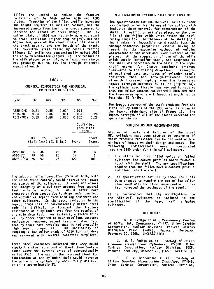
fillet toe tended to reduce the fractureresistare of the high sulfur A516 and A285plates. irnoothing of the fillet profile increasedthe height required to initiate failure, but theincreased energy from the higher drops appeared toincrease the amount of crack damage. The lowsulfur plate of A516 was not only more resistantto crack Initiation (higher drop height), but thehigher toughness of the steel limited the size ofthe crack opening and the length of the crack.The low-sulfur steel failed by ductile tearing(Figure 11) while the conventionally melted A516failed by delamination (Figure 12). The failure ofthe A285 plates to exhibit more Impact resistancewas probably due to its low through thicknessimpact strength.
Table 1
CHEMICAL COMPOSITION AND MECHANICALPROPERTIES OF STEELS
Type %C %Mn %P %S XS1
A285-GrCA516-70A516-70Ca
0.210.240.19
0.501.061.00
UTS YS(ksi) (ksi)
0.0140.0140.013
Elong.(%, 8 in.)
0.0190.0230.002
0.240.20
Cv,ft-lbs,(3/4 size)
70° F
Trans.ShortTrans.
A285-GrCA516-70A516-70Ca
667975
465652
252025
4417120
106
100
The adoption of a low-sulfur grade of A516, withinclusion shape control, would Improve the impactresistance of UF8 cylinders. It would not ensurethe integrity of a cylinder dropped from severalfeet onto a saddle, but would offer moreprotection from damage due to drops under one footand accidental impact from handling equipment andother cylinders. In the past, variation in theimpact properties of conventionally melted steelmade 1t difficult to forecast the fractureresistance of a cylinder type from the results ofa single drop test. For instance, a 10-ton thin-wall cylinder appeared to have excellent punctureresistance; however, recent tests of steel fromthat cylinder have revealed that it had unusuallyhigh impact properties. The possibility ofadopting a low-sulfur grade of A516 for cylinderswas reviewed with several potential suppliers.
Three steel companies indicated that they couldsupply the steel at a cost of about three cents apound above the current price of conventionallymelted A516. The use of the Improved steel forfabrication of the cylinder shell would Increasethe price of a cylinder by about fifty dollars,which 1s approximately 3%.
MODIFICATION OF CYLINDER STEEL SPECIFICATION
The specification for the thin-wall tails cylinderwas changed to require the use of low sulfur, withinclusion shape control, for construction of theshell. A restriction was also placed on the pro-file of the fillet welds which attach the stif-fening rings.(») The thinness of the shell (5/16Inch) makes is Impossible to directly test thethrough-thickness properties without having toresort to the expensive methods of weldingattachments to the upper and lower surfaces of theplates. At the suggestion of one of the millswhich supply low-sulfur steel, the toughness ofthe shell was specified on the basis of the uppershelf energy for Charpy specimens orientedtransverse to the rolling direction. Examinationof published data and tests of cylinder steelsIndicated that the through-thickness Impactstrength increased rapidly when the transverseimpact strength exceeded 50 ft-lbs (Figure 13).The cylinder specification was revised to requirethat the sulfur content not exceed 0.010% and thatthe transverse upper shelf impact strength not beless than 55 ft-lbs.
The impact strength of the steel produced from thefirst 176 cylinders of the 1985 order Is shown inthe lower, right-hand side of Figure 13. TheImpact strength of all of the plates exceeded thespecified minimum.
CONCLUSIONS AND RECOMMENDATIONS
Studies of tests and failures of the steelUF6 cylinders have been studied to determine iftheir fracture resistance can be improved with aminimum of Impact on their design and costs. Thefollowing modifications were incorporatedinto the 1985 order for thin-wall cylinders.
1. The stiffening ring fillet welds on failedcylinders had convex profiles which formed anotch with the shell. The new specificationsrequire that the fillet have a concave profileand blend into the shell.
2. The specification for the cylinder shell hasbeen changed to require the use of low-sulfursteel made with Inclusion shape control. Thishas increased the toughness of the steel.
It 1s recommended that the modifications tothe thin-wall cylinders be included In thespecification of the heavy wall shippingcylinders.
REFERENCES
1. W. R. Pedigo et a l . , Preliminary Testingof 10-Ton UF6 Containers, KY-477, Union CarbideCorporation, Nuclear Division, Paducah GaseousDiffusion Plant (PGDP), Paducah, Kentucky,February 10, 1965. UNCLASSIFIED
2. W. R. Pedigo et a l . . Testing of 10-TonUranium Hexafluoride Cylinders, KY-500, UnionCarbide Corporat ion, Nuclear D iv i s ion , PGDP,Paducah, Kentucky, October 22, 1965. UNCLASSIFIED
3. E. W. Ricliardson et a l . , Testing of11-Ton Uranium Hexafluoride Cylinders, KY-549,Union Carbide Corporation, Nuclear Division,
83

PGDP, Paducah, Kentucky,UNCLASSIFIED
May 15, 1968.
4. E. W. Richardson and. S. Bernstein,Additional Testing of 10-Ton Uranium HexafluorideCylinders, KY-631, Union Carbide Corporation,Nuclear Div is ion, PGDP, Paducah, Kentucky,September 15, 1971. UNCLASSIFIED
5. S. C. Blue et a l . , License Applicationfor Type 48HX Cylinder for Shipment of NaturalAssay UF6, KY-697, Union Carbide Corporation,Nuclear Div is ion, PGDP, Paducah, Kentucky,February 26, 1979. UNCLASSIFIED
6. DELETED
7. W. S. PeiHni, Evolution of EngineeringPrinciples for Fracture-Safe Design of SteelStructures, NRL Report 6957, September 23, 1969.
8. B. J. Eberhard et a l . , "Friction WeldDuct i l i ty and Toughness as Influenced by InclusionMorphology," The Welding Journal, 171S, July 1983.
9. R. I . Reynolds, Analysis of the 16Thin-Wall UF6 Cylinder Stiffening Ring and SupportSaddle Contact Point, KY/G-738, Union CarbideCorporation, Nuclear Division, PGDP, Paducah,Kentucky, February 10, 1984. UNCLASSIFIED
JCUSTOM-BUILT RELEASE'SYSTEM EMPLOYING ANEXPLOSIVE NUT MECHANISM
Fig. 1. View of Test Site with Cylinderin Position for Drop
Fig. 2. Measurement of Cylinder DeformationAfter Drop
BRITTLE FRACTURE
DUCTILE TEAR
THROUGH THICKNESSDIRECTION
Fig. 3. Location in Cylinder Fracture and RollingOrientation of Shell Plate
84
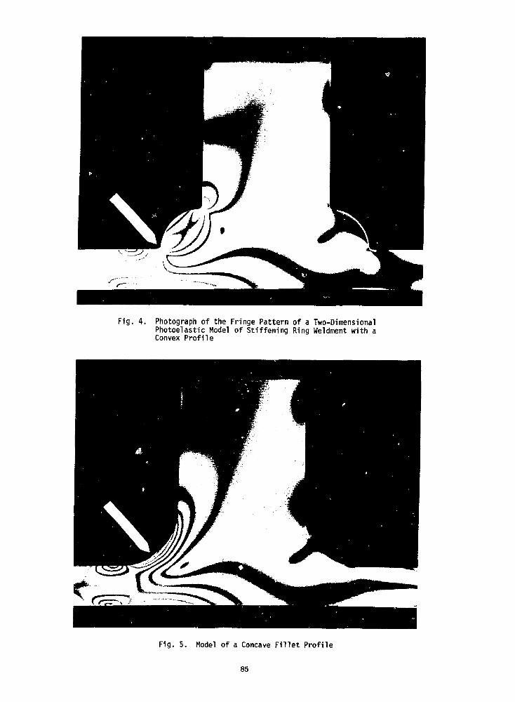
Fig. 4. Photograph of the Fringe Pattern of a Two-DimensionalPhotoelastic Model of Stiffening Ring Weldment with aConvex Profi le
Fig. 5. Model of a Concave F i l l e t Profi le
85

NOTE: TEST SPECIMENS FROM THIN WALL CYLINDERS. 5/16" TEST PLATES.(IMPACT STRENGTHS BASED ON FULL SIZE 10 mm SPECIMENS)
60
50
coGO
I
I 30UJEC
H
g 20
10
176 i 4173
/A/ / -iM
A285 (SHORT TRANS.)
A516 (SHORTTRANS.)
SOLID UF6 — I — LIQUID UF6
UF6 V.P. < 760 mm —j
0 40 80 100 160 200TEMPERATURE, °F
Fig. 6. Temperature Dependence of ImpactStrength of Cylinder Steels
Fig. 8. Drop Test System to Measure FractureResistance of Stiffened Steel Plates
Fig. 7. Frame for Holding StiffenedTest Plates
Fig. 9. Test Plate Fracture After Impact byFree Falling 1000-Pound Weight
86
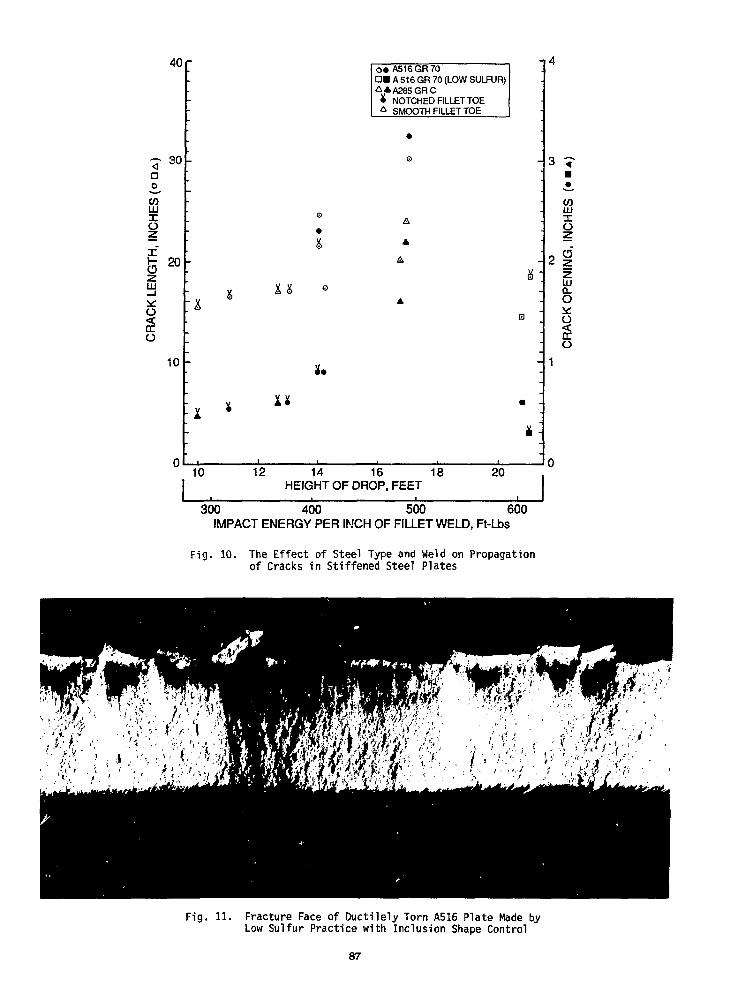
40 r
30ao
CO
o
(3LJJ
o<DC
o
20
10
l& °
O « A516GR70DM A 516 GR 70 (LOW SULFUR)A *A285GRC• NOTCHED FILLET TOE^ SMOOTH FILLET TOE
10 12 14 16 18 20HEIGHT OF DROP, FEET
300 400 5CK) 600~IMPACT ENERGY PER INCH OF FILLET WELD, Ft-Lbs
COLU
O
LU
o
o
Fig. 10. The Effect of Steel Type and Weld on Propagationof Cracks in Stiffened Steel Plates
Fig. 11. Fracture Face of Ductilely Torn A516 Plate Made byLow Sulfur Practice with Inclusion Shape Control
87
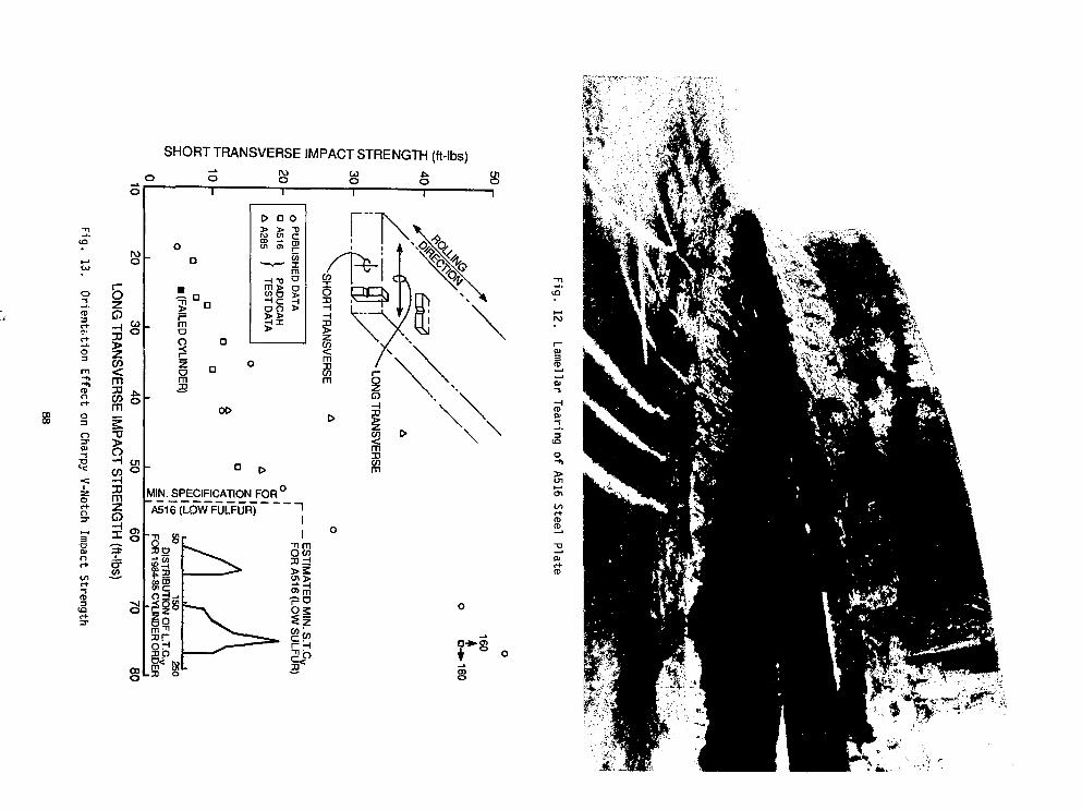
o-5
o3
O3
IZZ.
o
0)n
-sfD3
SHORT TRANSVERSE IMPACT STRENGTH (ft-lbs)
CO
m33 j i .
ffi*
3ccoo3J
mx"3
o oCO
o
mo
|
a
o£00Ol
*—v
Si
•eno>
2o j goATA
c5£
0"0cCDI—tnIrnO
si
oo
MIN. SPECIFICATION FOR°A516(LOWFULFUR)
" n SS
— C/)
09 CD
- | |a
o
\
"8
CD
O
>
inr+fD
Jft
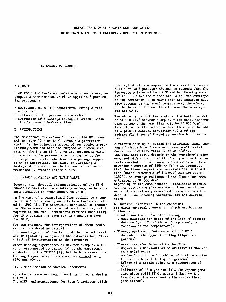
THERMAL TESTS ON UF 6 CONTAINERS AND VALVES
MODELISATION AND EXTRAPOLATION ON REAL FIRE SITUATIONS.
B. DURET, P. WARNIEZ
ABSTRACT
From realistic tests on containers or on valves, wepropose a modelisation which we apply to 3 particu-lar problems :
- Resistance of a 48 Y containers, during a firesituation.
- Influence of the presence of a valve.- Evaluation of a leakage through a breach, mecha-nically created before a fire.
I. INTRODUCTION
The resistance evaluation to fire of the UF 6 con-tainer, type 30 B or 48 Y, without a protectionshell, is the principal matter of our study. A pre-liminary work had been the purpose of a communica-tion to the PAIi'AM 83 [1]. We are continuing withthis work in the present note, by improving theanticipation of the behaviour of a package suppos-ed to be impervious, but also, by supposing aleakage at the valve and in the case of a breachmechanically created before a fire.
II. INTACT CONTAINER AND TIGHT VALVE
Because the physical characteristics of the UF 6cannot be simulated in a satisfying way, we have tobase ourselves on tests done with UF 6.
In the case of a generalized fire applied to a con-tainer without a shell, we only have tests conduct-ed in 1965 [2]. The experiment consisted in measur-ing the exposure time to a hydrocarbide fire, untilrupture of the small containers (maximal mass 113kgfor UF 6 against 2.3 tons for 30 B and 12.6 tonsfor 48 Y).
For two reasons, the interpretation of these testscan by considered as partial :- Unknowledgement of the type, of the thermal leveland of spreading in space of the external heat flow.- Lack of intrumentation in the container.
Other heating experiences exist, for example, a 10tons instrumented container [3] or the experienceconducted by the PRNFDC [4], but in both cases, theheating temperature, never exceeds, respectively93°C and 400°C.
II.1. Modelisation of physical phenomena
a) External received heat flow in a container duringa fire :The AIEA reglementations, for type A packages (v.hich
does not at all correspond to the classification ofa 48 Y or 30 B package) advises to suppose that thetemperature is equal to 800°C and by choosing emis-sities of .9 for the flames and .8 for the envelopeof the container. This means that the received heatflow depends on the steel temperature, therefore,on the internal thermal flow between the envelopeand the UF 6.
Therefore, at a 20cC temperature, the heat flux willbe 54 000 W/m2 and,for example,if the steel tempera-ture is 500°C the heat flux will be 40 000 W/m
2.In addition to the radiative heat flow, must be add-ed a part of natural convection (10 7. of theradiant flow) and of forced convection heat trans-port.
A recente note by F. NITSHE [5] indicates that, dur-ing a hydrocarbide fire around some small contai-ners, the heat flow value is of 25 W/m2oC.The real heat flow, depends on the container's sizecompared with the size of the fire ; we can base ontests carried out in France, with a crude oil fire,covering a surface of 2000 m2 [6] : it appeared,that the flame temperature decreases fast with alti-tude (which is maximum of 1 meter) and may reach1250°C, an average radiance of the flames has beenestimated at 30 000 W/m2.Depending on the case studied , (realistic calcula-tion or pessimiste risk estimation) we can chooseone of the previously described cases, as to intro-duce it as an incoming parameter for the calcula-tions.
b) Internal transfers in the containerPrincipal physical phenomena which may have aninfluence :- Conduction inside the steel lining
. well mastered (in spite of the lack of precisedata on X,P , Cp of the ordinary steel, as afunction of the temperature).
- Thermal resistance between steel and UF 6. depends on the type of filling (liquid ougaseous)
- Thermal transfer internal to the UF 6. Radiation : knowledge of an emissity of the UF6in a solid state
. conduction : thermal problems with the circula-tion of UF 6 (solid, liquid, gaseous)
. Effect of a triple point at a temperature of64°C
. Influence of UF 6 gas (at 54°C the vapour pres-sure above solid UF 6, equals 1 Bar) on thetransfer of the mass inside the cracks (heatpipe effect).
89

. Unknown convection
. Unknown boiling
. Critical point at 230°C. State equation.
In addition to these phenomena, we must add someinternal mass transfers, due to the important vapourpressures (70°C 1.8 Bar, 100°C i. 1 Bars and 120°C6 .5 Bars) ; such transfers may considerably increasethe apparent thermal conductivity ; it may then, bemultiplied by a factor 10, between ambiant tempera-tures and 65°C [1].Our work is actually leading us to propose an inter-nal heat transfer model), which has the followingprincipal characteristics :- Transient conduction inside the steel envelope- Radiation heat transfer and conduction to the in-interface steel - Solid UF 6
- Apparent good conductibility in the UF 6, allowingfor homogeneous temperature
- Increase of heat transfers while changing phases,from solid to liquid : transfer by boiling afterphase changing at 64°C.
c) RuptureRupture happens if the internal pressure involvesan over-strain of the rupture limit of the steel orif the liquid UF 6 fills all the available volume.This is a hydraulic rupture.It appears that, in the case of the UF 6 thermalmodel that we have chosen, the hydraulic ruptureappears before the mechanical rupture.
II.2. Application to real tests
The interpretation of the Japanese experiments [A]on 110 Kg of UF 6 containers electrically heatedpermits to verify our model of heat transfer in theUF 6.Main characteristics of a test at 400°C :- Heating by radiation of electrical resistors- Good knowledge of the STPT 38 steel temperatures- Temperature measurements in the UF 6.Tnt application of our model has been accomplishedby using a one dimensional transient approach.
The table 1 resumes the principal date used for thecalculation.
Table 1 SI Value
Geometry : External diameter .267Steel thickness .0286External surface 1.286Internal volume
Steel : Thermal conductivity 55Density 7850Heating capacity 490Coefficient of thermalexpansion 1.2 10Density at 20°C 5090Density at 64°C (solid) 4920
UF 6 Density (liquid) 4130-7.13 t (t in °C)Heat capacity (solid) 487Heating capacity (liquid) 558Gas thermal conductivity .007Fusion heat at 64°C 54480
-5
The heat exchange between steel and UF 6 is contro-led through a gas film (the initial thickness is0,9 mm); choosing an external emissivity of 0.6,which includes the radiation effect and a part ofthe convection linked to surrounding air, we thenobtain, a steel temperature equal to 96°C after20 minutes and 111°C at the 30th minute, the inter-
nal exchange by radiation, with an emissivity of 0.3is equivalent to the exchange by conduction throughthe film j about 700 W/m2.A calculation compared to a test is shown in fig.l.Steel temperature falls, when the UF 6 joins themelting point which is obtained at the 33 rd minute,then appears an homogeneisation of the temperaturesbetween steel and UF 6, the temperature is underestimated at 72°C, which means that the externalheat flow, during the heating period, may be moreimportant.When is noticed, on the one hand, that the steeltemperature does not exceed 120°C, and on the otherhand, that the diameter of the container is only1/6 th of a 48 Y. Then we will come to the conclu-sion that extrapolation of this model, on a big UF6container during a fire at a temperature of 800°C or1000°C, is hazardous.Nevertheless, by to calculating the tests conductedby MALETT [2] (the steel has arrived at a temperatureof 540°C during the test) we obtain a rupture afteraround 8 minutes if we suppose an external averageemissivity of .7. This time is experimentally verif-ied.
II.3. EXTRAPOLATION ON A FIRE AROUND A 48 Y
Supposing an internal heat transfer model, identicalto the previous case, we study the time until ruptu-re, with two assumptions :- First case : maximum external flow with a tempera-ture of 800°C and an emissivity Fire-Steel of .9 and.8, respectively adding a natural convection flowaround the cylinder.
- Second case : more realistic external flow, witha value of 30 kW/m3.
On the other hand we suppose that all the externalsurface receives the heat flow.In fig. 2 we give the transient temperature histo-ries between steel and UF 6, in both cas. By cal-culating the steel temperatures, which are important(above 500°C), we obtain internal radiative heatflows, which are 10 to 30 times above the heat flowdue to conduction through the gas film.In the first case, the hydraulic rupture (T of UF6148°C) happens after 41 minutes and 57 minutes inthe second case.
III. LOSS OF TIGHTNESS AT A VALVE
UF 6 industrial containers (30 B or 48 Y) are equip-ped with a valve and a plug. For the following rea-sons, we think that such accessories seem to bespecialy sensible, in the case of a fire :1) Thp tighrnpss of the valves and of the plug inobtained by using a layer of alloy which is appliedon their screwing points. Lead-tin alloy melts at200°C.2) The valves are made with materials having diffe-rent thermal dilatation coefficients. For examplethe body is made of aluminium and the rod is made ofmonel (See fig. n° 3).
III.l. Experiment
The experimental system, sketched on fig. 4, allowsa progressive or a sudden heating of a complete lotof valves.The electrical oven, equipped with a steel tube usedas a protection in case of a rupture of the valve,creates a hot surrounding (800°C).In order to avoid an eventual oxidization, we havechosen nitrogen for the tests. A metallic container
90

fixed on the support, with an interposed gasket isused to receive the valve leakage flow. The gas isthen conducted to nitrogen-water heat exchangespermitting to lower the nitrogen temperature to it'snormal temperature before passing in a flow meter
a) Progressive heating :The temperature measurements and the leakage measu-rements are conducted by imposing the oven tempera-tures by steps (100, 200, 300, 400°C) and then byvarying the pressure (5, 10, 20 and 30 bars).Five valves have been tested, (see recording in fig.5). The melting of the alloy is evident, neverthe-less, we have noticed the beginning of a leakage at100-150°C, which seems to indicate that a leakage,can be initiated by a differential dilatation ofvalve elements, even more important leakages thatthe thermal gradient, internal to the valve, is im-itnpor tant.
b) Sudden heating :All the devices are the same, but the valve and theplug are screwed on a sleeve which is welded samemeasurement thermocouples are in place.
The experiment consists to heat the oven, which issuspended above the valve, until obtention of asteady temperature (800°C) inside the steel tubeand bring the oven over the valve, which is maintai-ned at a pressure of 5 bars. The valve temperatureincreases, then we can note the time it takes andthe temperature level of the surrounding space atthe beginning of the leakage.If the gasket, made of PTFE (see fig.3) does notexist, a leakage appears after 1 minute and 25 se-conds, when the scriwing is at a temperature of78°C.For a completely equipped valve, the leakage startswhen the temperature is of 200°C (melting tempera-ture of the lead-tin alloy) after 4 minutes 50 se-conds .
111.2. Extrapolation on gaseous UF 6
If the valve has lost it's tightness, the leakagedepends, of the motor pressure, or during a fire,the leakage depends on the obtained temperature,which depends on internal thermal flow to the UF 6.Supposing that the UF 6 temperature is of 140°C,before a hydraulic rupture, the pressure wouldcause a leakage of about 2 N.m3/h of nitrogen inthe experiment .Supposing adiabatic behaviour of the UF 6, then :
"UF6=QNitrogen MUF6
2 T UF6V UF6 + 1
+ 1
Based on the previous choices Qupg = 0.55 m3/hwhich means that after hydrolysing we have an ema-nation of 0.5 g/s in HF.
IV. BREACH FOLLOWED BY A FIRE
The calculation supposes that the thermal flowincoming through the steel envelope allows to subli-mate a certain quantity of UF 6 which will be then,evacuated out of the 48 Y container. We have chosenthe model described in paragraph I, by adding thesublimation heat which is equal to 1.38 105 J/Kg.- First case : 800°C fire, of a duration of30 minutes, with a fire emissivity of .9 and a
container emissivity of .8 we considered also acontribution of natural convection.- Second case : the heat flow is 30 000 W/m2 andthe fire lasts 15 minutes (see results in fig. 6and 7) In any case, the steel envelope exits andhas an influence by it's thermal inertia ; theheating continues up to the time at which, anexternal intervention permits a fast cooling ofthe steel.
In the following table we present the main results:
Table 2
First case800°Cduration :30 minutes
Second case30 kW/m2
duration :15 minutes
UF6 Density evacuated (Tons)
ifintervention
3.44
1.1
withoutintervention
5.9
2.7
If the breach is small enough, *he pressure drop,and a shrinking related to a UF 6 deposition, candecrease considerably the leakage flow.
V. CONCLUSION
The uncertainty of our evaluations resides on twoimportant points.1. External heat exchange : it is variable becauseof the homogeneousity of the flames and the smokeinfluence, and the modification of the container'semissity. A modelisation is utopic because eachfire is a different case, which depends on :- the type of hydrocarbide- the exact position of the containerWe think that this exchange must be an incomingparameter of the calculation program, knowing thatit can involve variations on the rupture time, forexample around 50 %.2. Steel-UF 6 heat transfersBecause we actually, don't have high temperatureheating experiments with big diameter UF 6 contai-ners, we cannot give a definition of the momentswhen ruptures will happen on industrial containers,as the estimations can vary between 15 minutesand 1 hour on different models, but joining therupture time, in the MALLET tests [2].Different assumptions are possible :a) Considering the important UF 6 density, theheating can stay limited to the peripherical zonesgenerating some growing pressures which are locali-sed at the periphery.b) A part of the UF 6 can be liquefied and wouldbe accumulated at the bottom of the container,then two possibilities appears :- The container is involved intirely by fire,
including the bottom and involves an important.praying of UF 6, leading to a global heatingwith an excellent heat transfer and an earlyrupture of the envelope.
- The fire does not reach the liquid zone, and theexistence of a bad coefficient of the heat trans-fer between the lining and the solid UF 6 delaysthe UF 6 heating and the rupture of the contai-ner.
91
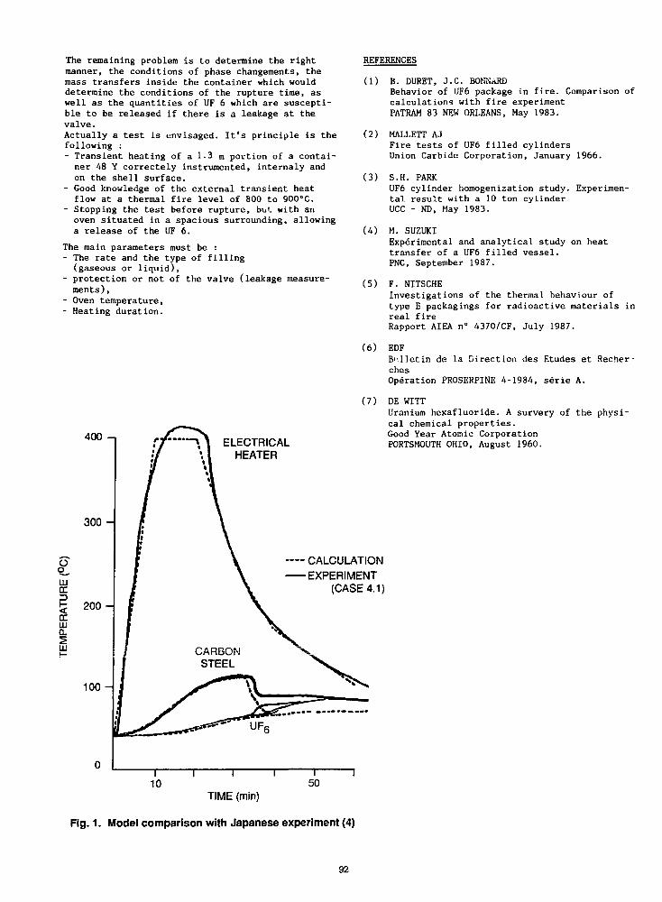
The remaining problem is to determine the rightmanner, the conditions of phase changements, themass transfers inside the container which woulddetermine the conditions of the rupture time, aswell as the quantities of UF 6 which are suscepti-ble to be released if there is a leakage at thevalve.Actually a test is envisaged. It's principle is thefollowing :- Transient heating of a 1.3. m portion of a contai-ner 48 Y correctely instrumented, internaly andon the shell surface.
- Good knowledge of the external transient heatflow at a thermal fire level of 800 to 900°C.
- Stopping the test before rupture, but with anoven situated in a spacious surrounding, allowinga release of the UF 6.
The main parameters must be :- The rate and the type of filling(gaseous or liquid),
- protection or not of the valve (leakage measure-ments ),
- Oven temperature,- Heating duration.
400 - , ELECTRICALHEATER
3 0 0 -
tiiDC
a.UJ
CALCULATIONEXPERIMENT
(CASE 4.1)
200 -
10 0 -
REFERENCES
(1) B. DURET, J.C. BONNARDBehavior of UF6 package in fire. Comparison ofcalculations with fire experimentPATRAM 83 NEW ORLEANS, May 1983.
(2) MALLETT AJFire tests of UF6 filled cylindersUnion Carbide Corporation, January 1966.
(3) S.H. PARKUF6 cylinder homogenization study. Experimen-tal result with a 10 ton cylinderUCC - ND, May 1983.
(4) M. SUZUKIExperimental and analytical study on heattransfer of a UF6 filled vessel.PNC, September 1987.
(5) F. NITSCHEInvestigations of the thermal behaviour oftype B packagings for radioactive materials inreal fireRapport AIEA n° 4370/CF, July 1987.
(6) EDFBulletin de la Direction des Etudes et Recher-chesOperation PROSERPINE 4-1984, serie A.
(7) DE WITTUranium hexafluoride. A survery of the physi-cal chemical properties.Good Year Atomic CorporationPORTSMOUTH OHIO, August 1960.
010
TIME (min)
Fig. 1. Model comparison with Japanese experiment (4)
92
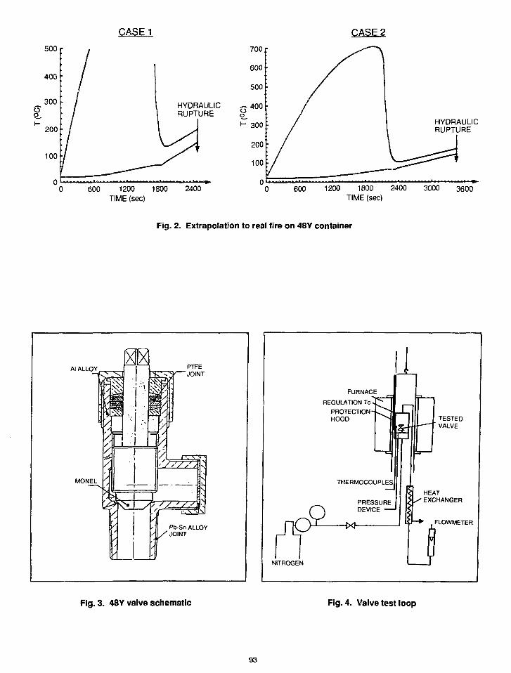
CASE 1
500 r
HYDRAULICRUPTURE
600 1200 1800TIME (sec)
2400
HYDRAULICRUPTURE
600 1200 1800 2400
TIME (sec)3000 3600
Fig. 2. Extrapolation to real fire on 48Y container
Al ALLOY
MONEL
Pb-Sn ALLOY/ JOINT
FURNACEREGULATION Tc -
PROTECTION -HOOD
PTHERMOCOUPLES,
PRESSUREDEVICE
NITROGEN
TESTEDVALVE
HEAT/ EXCHANGER
FLOWMETER
Fig. 3. 48Y valve schematic Fig. 4. Valve test loop
93
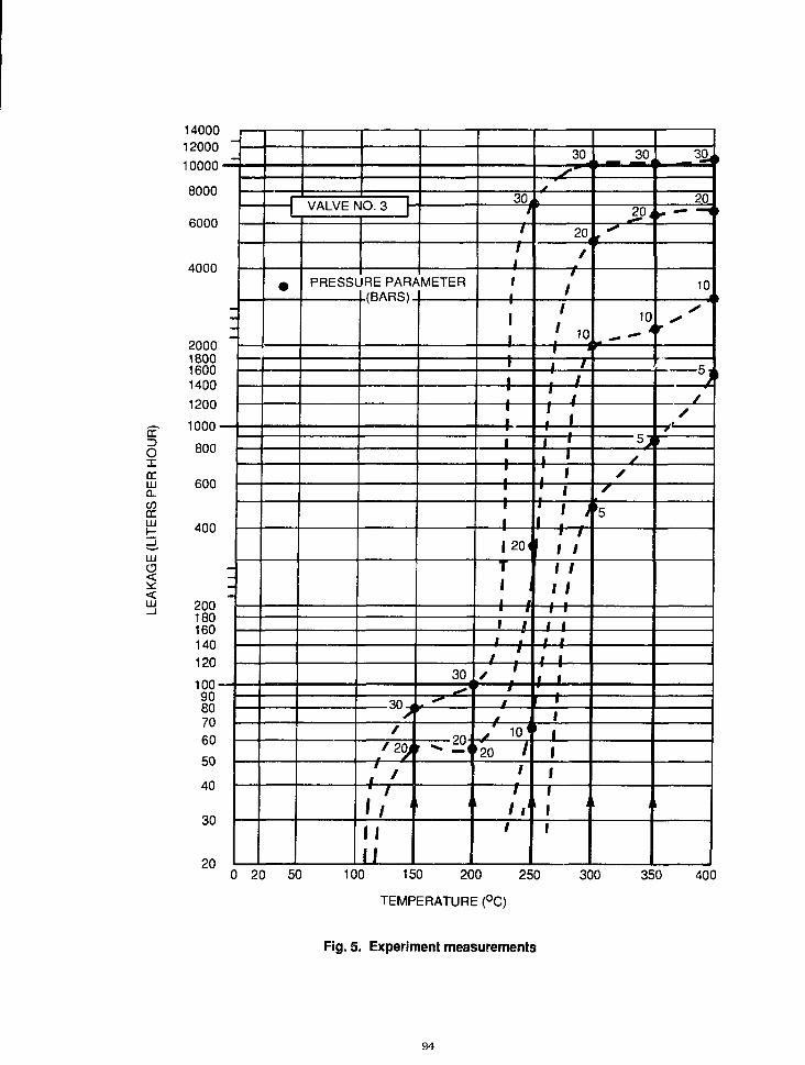
13
oxorina.CODCLJJ
LJJ
<LU
14000
12000
10000
8000
6000
4000
2000180016001400
1200
1000
800
600
400
200180160140120
100908070605040
30
20
1 1
1 1
•
VALVE t
PRESSl
40.3 -
JRE PAR/L(BARS)
sf
/20./
/
IfII
VMETER
30
oU
//
1•
1
1—'1
I1—1i
11| 20
T1• iI I1 /1 i
11 ,
1,
f 10'20 /
11 1
1
30
20
/
/
' 10
~~j T
T~Y~i• i
11
11
1 1
1 I
iii
i
i
_ 3°<201
10
5,s
/s
'5
30,
r '
10
r
A
0 20 50 100 150 200 250 300 350 400
TEMPERATURE (°C)
Fig. 5. Experiment measurements
94

kg kg/sec
800 r—
rr 600 —
LUor3
Si 400 —LU0 .
UJ
I I I I i I I I I I i I I I I I I I I i I I I I I I I t I I I I • I I I I I
200 —
600 1200 1800 2400
TIME (sec)
3000 3600
1—5000
— 4000
- 3 0 0 0
- 2 0 0 0
-1000
r-10
- 8
- 6
— 4
- 2
— 0
Fig. 6. Case 1 (fire duration = 30 min)
500 r—
kg kg/sec
r-4000 1—5
— 3000
— 2000
— 1000
- 4
- 3
- 2
— 1
300 600 900 1200 1500 1800 2100 2400 2700 3000 3300 3600
TIME (sec)
Fig. 7. Case 2 (fire duration = 15 min)
9 5 / ^ '
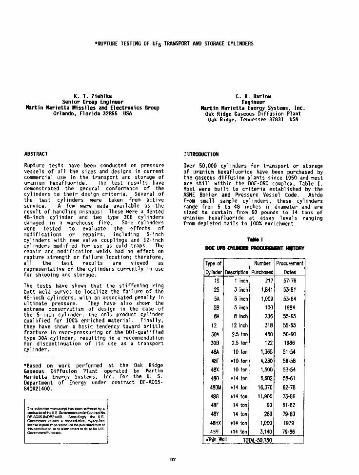
•RUPTURE TESTING OF UF6 TRANSPORT AND STORAGE CYLINDERS
K. T. ZiehlkeSenior Group Engineer
Martin Marietta Missiles and Electronics GroupOrlando, Florida 32855 USA
C. R. BarlowEngineer
Martin Marietta Energy Systems, Inc.Oak Ridge Gaseous Diffusion PlantOak Ridge, Tennessee 37831 USA
ABSTRACT
Rupture tests have been conducted on pressurevessels of all the sizes and designs in currentcommercial use in the transport and storage ofuranium hexafluoride. The test results havedemonstrated the general conformance of thecylinders to their design criteria. Several ofthe test cylinders were taken from activeservice. A few were made available as theresult of handling mishaps: These were a dented48-inch cylinder and two type 30B cylindersdamaged in a warehouse fire. Some cylinderswere tested to evaluate the effects ofmodifications or repairs, including 5-inchcylinders with new valve couplings and 12-inchcylinders modified for use as cold traps. Therepair and modification welds had no effect onrupture strength or failure location; therefore,all the test results are viewed asrepresentative of the cylinders currently in usefor shipping and storage.
The tests have shown that the stiffening ringbutt weld serves to localize the failure of the48-inch cylinders, with an associated penalty inultimate pressure. They have also shown theextreme conservatism of design in the case ofthe 5-inch cylinder, the only product cylinderqualified for 100% enriched material. Finally,they have shown a basic tendency toward brittlefracture in over-pressuring of the DOT-qual ifiedtype 30A cylinder, resulting in a recommendationfor discontinuation of its use as a transportcylinder.
•Based on work performed at the Oak RidgeGaseous Diffusion Plant operated by MartinMarietta Energy Systems, Inc. for the U. S.Department of Energy under contract DE-ACO5-840R21400.
The submitted manuscript has been authored by acontractor of the U .S. Go vernment under Contract No.DE-AC05-84OR21400. Accordingly, the U.S.Government retains a nonexclusive, royalty-freelicense to publish or reproduce the published form ofthis contribution, or to allow others to do so for U.S.Government Purposes.
PITRODUCTION
Over 50,000 cylinders for transport or storageof uranium hexafluoride have been purchased bythe gaseous diffusion plants since 1950 and mostare still within the DOE-ORO complex, Table I.Most were built to criteria established by theASME Boiler and Pressure Vessel Code. Asidefrom small sample cylinders, these cylindersrange from 5 to 48 inches in diameter and aresized to contain from 50 pounds to 14 tons ofuranium hexafluoride at assay levels rangingfrom depleted tails to 100% enrichment.
Tafttel
DOE U N CVUNDER PMCURBCNT MSTORY
Type ofCylinder
IS
2S
5A
5B
8A
1230A30B
48A
48T
48X
480
480M
48G48F
48Y
4SMX
43H
Description1 inch
3 inch
5 inch5 inch
8 inch
12 inch
2.5 ton2.5 ton
10 ton
*10 ton10 ton
*14 ton
•14 ton
»14 ton14 ton
14 ton
•14 ton•14 ton
Number
Purchased217
1,841
1,009100
236
318
450
122
1,365
4,2301,500
6,602
16,370
11,90090
260
1,000
3,140
Procurement
Dates57-76
53-81
53-64
1984
55-65
55-65
50-60
1986
51-54
56-5853-54
58-61
62-78
73-86
61-62
79-80
197979-86
.Thin Wall TOTAL-50.750
97
The cylinders intended for long-term storage ofdepleted process tails are primarily 48-inchdiameter cylinders designed for workingpressures of 100 psig. These have capacities of10 and 14 tons and have a nominal wall thicknessof 5/16 inch. Cylinders of similar UFgcapacity, which were designed for transport ofUFg as feed material and as low-enrichmentproduct, have a wall thickness of 5/8 inch andare nameplate-rated for ZOO psig workingpressure. The 48-inch cylinders have beenprocured in a number of design modificationsinvolving primarily external fittings andhardware. The pressure envelope, however, issimilar for all these designs, with the two wallthicknesses distinguishing tails storagecylinders from those intended for shipment ortransfer of feed or product materials. Thesecylinders are made from mild steels conformingto ASTH plate specifications A516 or A285,depending on procurement date. Strength levelsfor these steels are in the 55,000 to 70,000 psirange. All were manufactured as Code vessels.
Steel product cylinders of 2-1/2 ton capacityhave been manufactured in two configurations,designated 30A and 30B. The 30B cylinder, witha ?00 psig working pressure designation, is ofconventional pressure vessel configuration andwas manufactured as a Code vessel. The 30Acylinder, similar to the standard 1-ton chlorinecylinder, was manufactured to DOT specificationsand consists of a seam-welded right circularcylinder with concave heads attached by forgewelding. Its working pressure is 250 psig. Thedesign has been declared obsolete for UF5service in favor of the 30B design, but thereare over 3,000 such cylinders on hand, mostmanufactured prior to 1945 as chlorine cylindersand subsequently modified for UFg use. Somewere manufactured in the 1950 to 1960 period,and an additional small lot was manufactured in1984. About 1,000 are in use in storage of UFcmaterial, and some still serve in transport ofenriched product material.
The smaller product cylinders, all rated forworking pressures of 200 psig, are made fromnickel or Monel. Two 12-inch, 460-poundcapacity cylinders are in use - a spun, seamlessnickel cylinder, and a seam-welded Monelcylinder. The 8-inch, 265-pound cylinder, madefrom seam-welded sheet and formed ellipsoidalheads, is made from either nickel or Monel, asis the 5-inch model of 55-pound capacity whichis fabricated from standard pipe and weld caps.All of the nickel and Monel cylinders werefabricated as Code-compliant vessels, althoughweld modifications made on many of the 12-inchnickel cylinders and most of the 5-inch Monelcylinders have invalidated the codeclassifications which initially applied.
The design considerations in the ASME Codespecify a maximum stress in the cylinder wallwhich generally identifies the maximumhydrostatic test pressure and, hence, theworking pressure (half of the hydrostatic testpressure for this group of UFs cylinders).Where the wall thickness is selected based onthese considerations, the burst pressure will
generally be about eight to ten times theworking pressure. Notable exceptions in thepresent group of cylinders are the 30A cylinderwhich, as earlier noted, is not an ASME design,and the 5-inch cylinders which, although builtas Code vessels, develop only a small fractionof the allowable stress at the specified testpressure.
At various times over the past 25-30 years,design and safety studies related to UFgpackaging for storage and transport have beensupported in part by burst testing of UFgcylinders. These tests have covered most of thecylinder varieties in present use in the uraniumfuel cycle, including the two exceptions to thestandard designs noted above. This reportpresents the test data accumulated in recenttests of large product and storage cylinders,tests of weld-modified 5-inch and 12-inchcylinders, tests on a pair of fire-exposed Model30B cylinders, tests on two Model 30A units, andtests on 5-, 8-, and 12-inch cylinders insupport of a packaging development program.Some of the earlier tests were covered inindividual reports or internal memoranda; testson the large cylinders have not been previouslyreported.
SUMMARY
Nickel and Monel product cylinders in 8-inch and12-inch sizes gave burst pressures of 12 to 15times the nameplate working pressure. The 5-inch cylinder, manufactured from schedule 40pipe and developing only a small fraction of theallowable stress at the specified hydrostatictest pressure, proved to be an extremelyconservative design and failed at 40 times therated working pressure.
The Model 30B steel cylinder, of similar designand configuration, gave burst pressures 11.3 and11.8 times the 200 psig working pressure. Thedesign - obsolete 30A cylinders, with a workingpressure of 250 psig, showed sudden headreversal at 900-1,000 psig and (brittle) failureby head separation at 1,250 psig for a safetyfactor of only 5.0.
The large (48-inch) shipping and storagecylinders, of conventional design but with addedexternal stiffening rings, suffered somestrength reductions and lowered safety factorsbecause of end-joint failures in the stiffeningrings during the burst tests. Safety factors of8.8, 8.7, and 6.4 were observed in tests on onethin-wall storage cylinder and two heavy-wallteed cylinders.
PROCEDURE
In general, the test cylinders were obtainedfrom active service for burst testing. In somecases, they had been damaged in handlingaccidents and did not qualify for furtherservice without detailed examination,evaluation, and repair of the damage. Two 30Bcylinders were obtained from a transportservices firm in the feed enrichment cyclefollowing their exposure to a warehouse firewhich subjected them to temperatures as high as

Table II.RUPTURE TEST DATA FOR UF6 CYLINDERS
CylinderType
5A
5A
SA
8B
12A
1 2B3 0 A
3 0 B
480M4 8 Y
4 8 A
Material
MonelMonel, NickelCouplingMonelNickelNickelMonelSteel (A285)Steel (A516)Steel (A285)
Steel (A516)
Steel (A285)
WallThickness
Inch
1 / 4
1 / 4
3/16
3/16
O.2OO
0.250
13/32
1 / 2
5/16
5 / 8
5 / 8
WorkingPressure
PSI
2 0 0
2 0 0
2OO
2 0 0
2 0 0
2 0 0
2 5 0
2 0 0
1OO
2OO
2 0 0
RupturePressurra
PSI
8250
7950
2950
2450
24OO
2260
1 250
2270,236O
8 7 0
1 77O
1285
PercentVolumeIncrease
2 1
3 0
5 3
2 0 *
3 4
9
6
6
* The vo/ume increase of the JOA cy/inder isdue to inversion of the concave heads atan interno/ pressure of POO - / , OOO psi.
1600°F. One 48-inch cylinder, never in service,was dented and thus not suitable for filling.Three 12-inch cylinders were tested from a groupof cylinders weld-modified for use as cold trapsin UFg collection. A weld-modified 5-inchcylinder was tested to evaluate the effects of amaterial substitution in the cylinder head andvalve coupling.
Where necessary, ihe cylinders were cleaned anddecontaminated. In some cases, this includedsandblasting the exterior surfaces so thatstrain gages could be attached to monitor thepressure tests. The cleaned, prepared cylinderswere then fitted with new valves or specialadapters, completely filled with water andconnected to one of several high-pressurepumping systems. Pressure was monitored with alarga, calibrated pressure gage; and, inaddition, for the tests on the 48-inch and 5-inch cylinders by a transducer whose output wasrecorded periodically in a computerized dataacquisition system. For the tests conductedprior to 1970, the cylinders were covered withheavy, woven rope explosion mats; later testswere conducted in a pit under a heavy steelcover. Failures in these latter tests wereobserved in a video monitor and some were video-taped to provide a permanent record.
The failures were photographed; and, in manycases, a volume was determined by measuring thecylinder distortion at several locations.Analysis of strain gage data gave information oncylinder response to pressure during the tests.Failure pressure data are presented in tabular
form, Table II. A photograph of a typical 48-inch cylinder failure (influenced by thepremature failure of the end-weld joint in astiffening ring) is also shown, Figure 1.
DISCUSSION
Most of the cylinder types in present use fortransport of uranium hexafluoride areconservatively designed to criteria establishedby the ASME Boiler and Pressure Vessel Code, andburst tests conducted over a span of many yearshave demonstrated the safety against over-pressuring inherent in these designs. Wherewall thicknesses are selected on the basis ofthe Code maximum allowable stresses, the designsyield a minimum safety factor of eight times thespecified working pressure, and conservatism inspecification of minimum ultimate strengthvalues for the selected materials gives, inpractice, actual safety factors in the range of10 to 15 times the working pressure.Examination of the test data shows this to betrue of the 8- and 12-inch nickel and Monelproduct cylinders and of the 30B steel productcylinder. Design minimum safety factors of 8:1are achieved in the 48-inch cylinders, butconsistency in this respect is handicapped bythe difficulty of assuring the specified full-penetration welds in the end joint in theexternal stiffening rings. In the three testson 18-inch cylinders covered in this report,failure in all cases began in the stiffeningring joint and progressed through the attachmentweld and into the pressure envelope at a net
gg
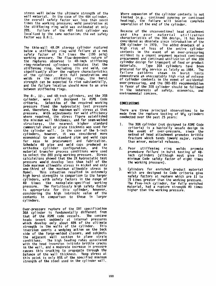
stress well below the ultimate strength of thewall material. In the case of the 48A cylinder,the overall safety factor was less than seventimes the working pressure; weld penetration atthe stiffening ring weld was estimated at only20%. Failure of the 48Y test cylinder waslocalized by the same mechanism; the net safetyfactor was 8.8:1.
The thin-wall 48.OM storage cylinder rupturedbelow a stiffening ring weld failure at a netsafety factor of 8.7 times the (100 psig)working pressure. The flaw-dependent nature ofthe ruptures observed in 48-inch stiffeningring-reinforced cylinders indicates that thestiffening ring, including its end weld, cansignificantly alter the rupture characteristicsof the cylinder. With full penetration endwelds in the stiffening rings, the burststrength can be expected to rise substantially,and the failure location should move to an areabetween stiffening rings.
The 8-, 1Z-, and 48-inch cylinders, and the 308cylinder, were all designed to ASME Codecriteria. Selection of the required workingpressure fixed the hydrostatic test pressureand, therefore, the maximum wall stress at thatpressure. With adjustments for weld efficiencywhere required, the stress figure establishedthe minimum wall thickness, and for seam-weldedstructures, the nearest higher standardcommercial sheet or plate thickness was used forthe cylinder wall. In the case of the 5-inchcylinders, however, it was considered moreeconomical to use standard pipe and weld capsfor ease in procurement and fabrication.Schedule 40 pipe and weld caps produced anorthodox cylinder configuration, and thematerial transfer process conditions were usedto select the 200 psig working pressure. Stresscalculations showed that the 2X hydrostatic testpressure would develop less than half of theCode maximum allowable stress in nickel and onlyone-third of the maximum allowable stress inMonel. This situation resulted in extremelyhigh burst strengths in comparison to the largercylinders, with safety factors in the range of40 times the nameplate-specified workingpressure. The fortuitously high safety factoris appropriate for this cylinder, however,considering the high intrinsic value of thecontents in comparison to those in largercylinders.
Over-pressure rupture of the DOT specification30A cylinder is fundamentally different fromthat of the ASME code vessels. The concaveheads invert suddenly at internal pressureswhich develop only about 60% of the ultimatestrength in the walls of the cylinder. Thisinversion exerts a wedging action on the backside of the forge-welded closure, and subjectsthe adjacent wall section to plane strainconditions. The high loading rates associatedwith the head inversion initiate brittle cracksin the wall, and a moderate increase in pressurecauses this cracking to propagate through thebalance of the wall thickness. Hoop stress atthis point is only 85% of the specified minimumstrength of the steel used in the cylinder wall.
Where expansion of the cylinder contents is notlimited (e.g., continued pumping or continuedheating), the failure will involve completeseparation of the end of the cylinder.
Because of the unconventional head attachmentand the poor material utilizationcharacteristics of the 30A design, it has beenconsidered as obsolete since introduction of the30B cylinder in 1970. The added drawback of ahigh risk of loss of the entire cylindercontents in the event of an over-pressuringaccident is a cogent argument against continuedprocurement and continued utilization of the 30Acylinder design for transport of feed or productmaterials. Type 30A cylinders have beenprocured for UF6 service as lately as 1984. Thefailure patterns shown in burst testsdemonstrate an unacceptably high risk of releaseof cylinder contents in the event of accidentalover-pressuring, and the 0R0-651 recommendationin favor of the 30B cylinder should be followedin the interests of safety, economics, andenvironmental concern.
CONCLUSIONS
There are three principal observations to bemade from the rupture testing of UF5 cylindersconducted over the past 25 years:
1. The 30A cylinder (not designed to ASME Codecriteria) is a basically unsafe design inthe event of over-pressure, since themethod of head attachment promotes brittlefracture which tends toward major, ratherthan minor, material releases.
2. Poor stiffening ring welds promotepremature failure in burst testing of 48-inch cylinders (although most give theminimum Code safety factor of eight timesthe working pressure).
3. Cylinders for enriched product materialwhich are designed to Code criteria givesafety factors at rupture which are 11 to15 times greater than the working pressure.The five-inch cylinder, for fully enrichedmaterial, had a rupture strength 40 timeshigher than the working pressure.
100
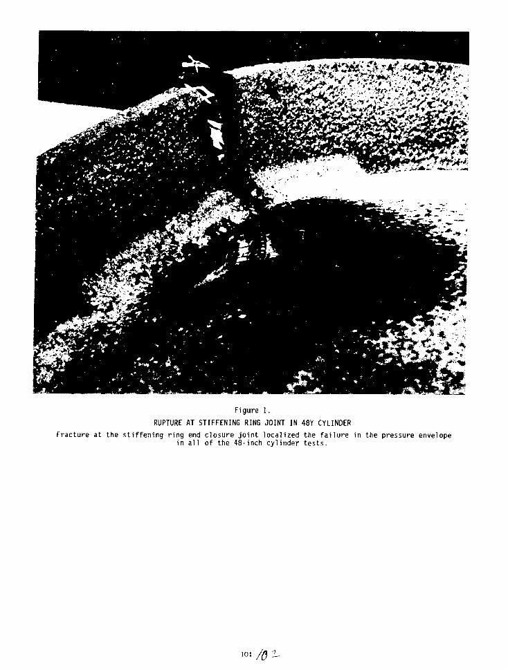
Figure 1.
RUPTURE AT STIFFENING RING JOINT IN 48Y CYLINDER
Fracture at the stiffening ring end closure joint localized the failure in the pressure envelopein all of the 48-inch cylinder tests.
101
MONITORING OF CORROSION IN ORGDP CYLINDER YARDS*
H. M. Henson
Oak Ridge National LaboratoryMartin Marietta Energy Systems, Inc.
Oak Ridge, Tennessee 37831
J. L. Frazier
Oak Ridge Gaseous Diffusion PlantMartin Marietta Energy Systems, Inc.
Oak Ridge, Tennessee 37831
C. R. Barlow
Oak Ridge Gaseous Diffusion PlantMartin Marietta Energy Systems, Inc.
Oak Ridge, Tennessee 37831
K. T. Ziehlke
Martin Marietta Missiles and Electronics GroupOrlando, Florida 32855
ABSTRACT
Process tailings from U.S. uranium isotopeenrichment activities are stored in mild steelcylinders designed and manufactured according toASME Boiler and Pressure Vessel Code criteria.Most storage facilities are open areas adjacent tothe enrichment plants where the cylinders areexposed to weather; approximately 5000 cylindersare in several cylinder yards at the Oak RidgeGaseous Diffusion Plant (ORGDP). Since mild steelwill corrode under these storage conditions,significant work is being done to determine generalcorrosion behavior of tails cylinders and toestimate anticipated lifetimes.
The program under way at the ORGDP is targeted atconditions specific to the Oak Ridge cylinderyards. The work includes (a) determination of thecurrent conditions of cylinders stored in theseyards, (b) description of rusting behavior inregions of the cylinders showing acceleratedattack, (c) the monitoring of corrosion ratesthrough periodic measurement of test coupons placedwithin the cylinder yards, and (d) establishment ofa computer base to incorporate and retain thesedata.
The information obtained will enhance planning forcontinuing safe storage of the tails material.
INTRODUCTION
Uranium hexafluoride (UFg) throughout the nuclearfuel cycle is handled and stored in cylinders whichare designed, manufactured, and maintained inaccordance with the ASME Boiler and Pressure VesselCode for unfired pressure vessels (Section VIII).There are presently more than 40,000 of thesecylinders within the DOE Oak Ridge Operationscomplex currently used for the storage ofisotopically depleted material (process tailings).
•Based on work performed at Oak Ridge NationalLaboratory and Oak Ridge Gaseous Diffusion Plantoperated for the U.S. Department of Energy undercontract DE-AC05-840R21400 with Martin MariettaEnergy Systems, Inc.
These tails cylinders, in 10 and 14 ton sizes, are48 in. in diameter, and are constructed of mildsteel. Most cylinder storage facilities are openareas adjacent to the enrichment plants, where thecylinders are exposed to weather. Mild steelwill corrode under these conditions, presenting theneed for the monitoring of cylinders in storage toprovide assurance that they have not deterioratedto the extent that they no longer meet wallthickness requirements for shipping and handling.
Cylinders used for transport of isotopicallyenriched materials are of heavier construction(5/8 in. wall construction rather than 5/16 in.)than these tails cylinders; they also see moreactivity than tails storage cylinders, and aretherefore subject to relatively frequent visualobservation and cleaning, as well as periodicpressure testing during which potentially hazardousconditions may be detected and evaluated. Tailscylinders in storage are subjected routinely onlyto periodic inventory; no cylinder inspection isrequired until the cylinders are either emptied ortransported.1
At one time, feed materials were transportedexclusively in cylinders rated for 200 psi workingpressure, the same design utilized for product(enriched) material. In frequent use in the fuelcycle, they too were subjected to periodiccleaning, inspection, and hydrostatic testing.Present practice, however, allows one-time use of anew 100 psi cylinder for UFg transport, after whichit is used for tails storage at its destination.As a storage cylinder, it sees no further formalinspection. The cylinder yards are thereforeoccupied by three populations of storage cylinders:
1. Obsolete feed cylinders rated at 200 psiworking pressure with nominal 5/8 in. wallthickness.
2. Thin (5/16 in.) wall cylinders code-rated for100 psi working pressure, designed and built asstorage cylinders.
3. Thin wall cylinders built as one-time use feedcylinders, then diverted to tails storage atthe receiving site. These cylinders were builtto the same specifications as the storagecylinders in category 2.
103
Categories 2 and 3, the thin (5/16 in.) wallcylinders, are the initial focus of this corrosionwork.
The mild steels used in UFs cylinder constructionare pressure vessel grades of plate steel, coveredoriginally by ASTM A285, then since 1978 by ASTMA516 standards. They undergo a general atmosphericcorrosion attack; they are also subject to pittingor other localized damage under exposure conditionswhere moisture is maintained in contact withcylinder surfaces, and particularly where thismoisture may be contaminated by chemical specieswhich dissociate in solution to form high-conductivity electrolytes. These corrosionprocesses will eventually reduce wall thickness tothe point where the cylinder contents cannot besafely removed by liquefaction, but requiresublimation emptying, a process both slow andcostly. A cylinder with reduced wall strength dueto corrosfon would be more susceptible to handlingdamage during transport; damage to a cylinderduring transport also involves potentialenvironmental shock.
An extensive cylinder life study has been under wayat the Paducah Gaseous Diffusion Plant to estimatethe anticipated lifetime of storage cylinders.2Their data indicate that cylinders are generallyexpected to retain ASME Code qualification for atleast another twenty years. The Oak Ridge workdescribed in this paper supplements the Paducahstudy by examining conditions specific to the OakRidge cylinder yards, and determining localdifferences in corrosion rate related to cylinderyard location and storage condition of individualcylinders.
A four-faceted program is under way in Oak Ridge.Initial objectives are to determine the currentcondition of cylinders in outside storage at ORGDP,and mark those found to show marked deterioration.The program includes measuring corrosion rates tobe anticipated in storage yards throughpreparation, deployment, and analysis of ASTHcorrosion test coupons and commercial corrosionprobes. It establishes and maintains a continuinginspection program of cylinders in storage, withstatistically controlled measurements of wallthickness and records of corrosion activity. Itfurther provides documentation through a completedata base to include cylinder manufacturing data,service history, corrosion observations, andlocation. Our work could be readily extended to anyfacility where cylinders are kept in storage forsignificant periods of time.
OAK RIDGE CYLINDER YARD CONDITIONS
Cylinder degradation is expected to take placeprimarily from exposure to the environment.Atmospheric corrosion of mild steel varies from 1to 10 mils per year; UF5 corrosion at the insidewall surface is expected to be less than0.1 mil per year.3'4'5
Weathering attack depends on the presence ofsurface moisture; corrosion rate is, therefore,influenced markedly by relative humidity. Surfacetemperature will affect both the corrosion kineticsand the presence of surface moisture. Position ofthe cylinder yards with respect to plant emissionsand plant operating parameters will influenceattack rate. Air circulation and sunlight will
also affect steel deterioration. Retention ofmoisture in contact with the steel surface,particularly where the moisture contains mineralsalts, can promote localized attack or pittingcorrosion where penetration rates can exceedgeneral corrosion rates by a factor of 10 or more.
Oak Ridge rainfall varies in pH from about 3.7 to5.2. The acidity of the rainfall has a highlylocalized character, even within an individualshower; however, not much rain is expected to falloutside the limits where significant accelerationof corrosion will occur (Fig. 1). Pitting due toparticulate deposition is of more concern; scanningelectron microscopy and energy-dispersive X-rayanalysis have identified sulfur-bearing particleswhich have been deposited on the cylinder surfaces(Fig. 2).
Relative humidity in Oak Ridge is high; in thesummer exposed steel surfaces at ambienttemperatures can be expected to be covered with athin film of condensed moisture at least half thetime. Lower cylinder walls where the metal is incontact with solid UF5 retain this moisture filmover longer periods of time, and would be expectedto suffer more corrosion damage.
Approximately 3000 storage cylinders in theK-1066-G yard were moved to a new location,K-1066-K in 1983-1984 (Fig. 3). Detailedobservations were made on many of the cylinders atthat time6'' revealing accelerated general attackand pitting in support areas shielded by woodensaddles on which the cylinders rested, andsimilarly accelerated corrosion in the head area ofthe skirted cylinders where the skirt accumulatesmoisture, rust, and dirt. Both of these areasshowed pit depths of 60 mils, superimposed on moregeneral wall thinning that, in total, reduced wallthickness in several cases to below the minimumvalue required by ASME Code criteria for workingpressure of 100 psi.
General wall thinning on the upper surfaces ofthose cylinders was estimated at the time of themove to be only about 35 mils, even though windrose patterns measured at ORGDP (Fig. 3) indicatethat for a significant fraction of time cylinderslocated in the K-1066-G yard were downwind from thenearby steam plant. This amount of thinning isconsistent with Paducah results,2 which estimateless than 2 mils per year general attack rate.
Oak Ridge cylinder yard inspections are focussed onareas which represent potential problem regions.Visual inspection of the storage cylinders isunder way. Ultrasonic measurement equipment hasbeen adapted for easy use in the yards and fieldmetallography techniques are being used to(a) determine the present status of storedcylinders, then (b) track the rate of deterioration.Cylinders identified as no longer conforming tocode will be set aside for special handling. Thewall thickness data, and any other pertinentobservations (valve and plug conditions, damage)made during the projected periodic inspections, arebeing included in a computer data base.
A significant amount of data to be used as a guidefor cylinder inspections is being obtained from thedestructive evaluation (Fig. 4) of a Type Pcylinder procured in 1951 from the Dallas TankCompany and fabricated of A285 steel. This
104
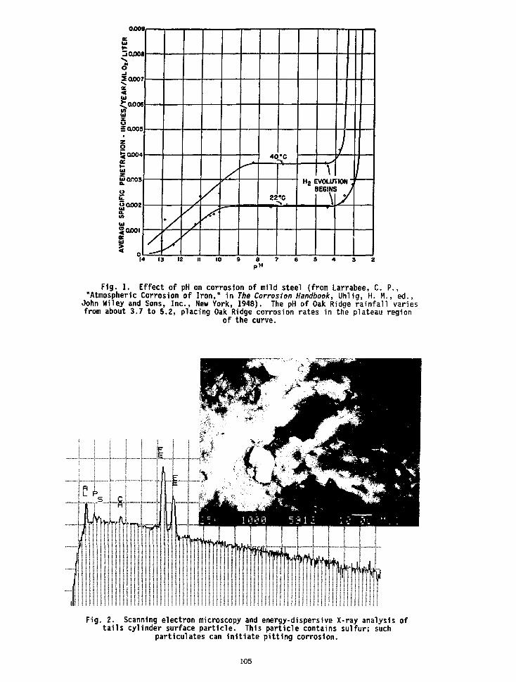
RA
TIO
N -
IN
CH
ES
/YE
AR
/ML O
t/L
ITE
RA
VE
RA
GE
S
PE
CIF
IC
PE
NE
T
yy
/
/ 22 ^C
H 2 E\
V0LU1IE6IN!
/
7
13 IS 10 8 7pH
Fig. 1. Effect of pH on corrosion of mild steel (from Larrabee, C. P.,"Atmospheric Corrosion of Iron," in The Corrosion Handbook, Uhlig, H. M., ed.,
John Wiley and Sons, Inc., New York, 1948). The pH of Oak Ridge rainfall variesfrom about 3.7 to 5.2, placing Oak Ridge corrosion rates in the plateau region
of the curve.
Fig. 2. Scanning electron microscopy and energy-dispersive X-ray analysis oftails cylinder surface particle. This particle contains sulfur; such
particulates can initiate pitting corrosion.
105
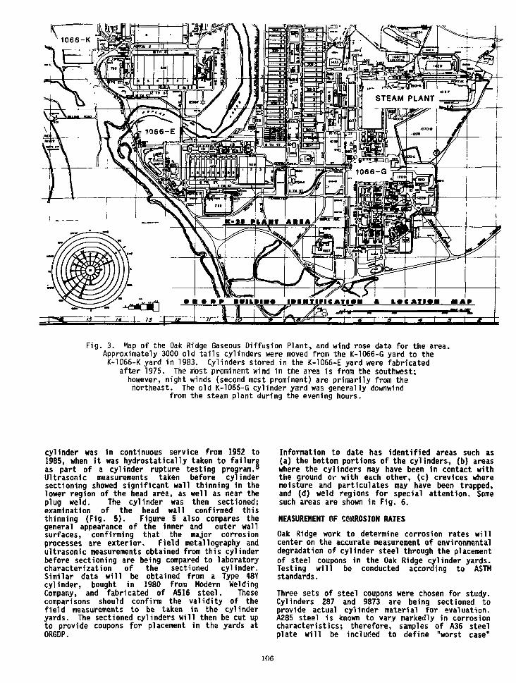
K —
1066-K
Fig. 3. Map of the Oak Ridge Gaseous Diffusion Plant, and wind rose data for the area.Approximately 3000 old tails cylinders were moved from the K-1066-G yard to theK-1066-K yard in 1983. Cylinders stored in the K-1066-E yard were fabricated
after 1975. The most prominent wind in the area is from the southwest;however, night winds (second most prominent) are primarily from thenortheast. The old K-1066-G cylinder yard was generally downwind
from the steam plant during the evening hours.
cylinder was in continuous service from 1952 to1985, when it was hydrostatically taken to failureas part of a cylinder rupture testing program.8
Ultrasonic measurements taken before cylindersectioning showed significant wall thinning in thelower region of the head area, as well as near theplug weld. The cylinder was then sectioned;examination of the head wall confirmed thisthinning (Fig. 5). Figure 5 also compares thegeneral appearance of the inner and outer wallsurfaces, confirming that the major corrosionprocesses are exterior. Field metallography andultrasonic measurements obtained from this cylinderbefore sectioning are being compared to laboratorycharacterization of the sectioned cylinder.Similar data will be obtained from a Type 48Ycylinder, bought in 1980 from Modern WeldingCompany, and fabricated of A516 steel. Thesecomparisons should confirm the validity of thefield measurements to be taken in the cylinderyards. The sectioned cylinders will then be cut upto provide coupons for placement in the yards atORGDP.
Information to date has identified areas such as(a) the bottom portions of the cylinders, (b) areaswhere the cylinders may have been in contact withthe ground or with each other, (c) crevices wheremoisture and particulates may have been trapped,and (d) weld regions for special attention. Somesuch areas are shown in Fig. 6.
MEASUREMENT OF CORROSION RATES
Oak Ridge work to determine corrosion rates willcenter on the accurate measurement of environmentaldegradation of cylinder steel through the placementof steel coupons in the Oak Ridge cylinder yards.Testing will be conducted according to ASTMstandards.
Three sets of steel coupons were chosen for study.Cylinders 287 and 9873 are being sectioned toprovide actual cylinder material for evaluation.A285 steel is known to vary markedly in corrosioncharacteristics; therefore, samples of A36 steelplate will be included to define "worst case"
106

conditions. Two groups of each steel will bepositioned in racks constructed in accordance withASTM G50-76, Standard Practice for ConductingAtmospheric Corrosion Tests on Metals. A rack willbe oriented in the cylinder yard facing south inaccordance with ASTM G50-76. Other coupons will beplaced in the yards to supplement the ASTM datawith data more specifically reflecting corrosionrates in the regions of the cylinders whereaccelerated attack might be expected.
Each set of steel coupons will consist of severalgroups. A standard group of 4 in. * 6 in.(preferred ASTM G50-76) with no coupon surfacepreparation otner than cleaning will be initiallyweighed and surface area measured in accordancewith the provisions of ASTM Gl-81. Data will berecorded in accordance with ASTM G33-72. Allcoupons will be removed at 1 year, 2 years,4 years, 8 years, and 16 years. Weight gain willbe recorded, then weight loss after scale removal.
A second group of coupons will be instrumented fortime of wetness measurements. A third group of1 in. coupons will be prepared metallographicallybefore placement in the yards; these coupons willbe sacrificed at each periodic removal for surfaceand nicrostructural characterization of thecorrosion process as It proceeds from a surfacerepresentative of the bulk material. A fourthgroup will consist of 1 in. coupons taken fromareas which include weld and heat-affectedmetal. These will also be sacrificed for surfaceand microstructural characterization. The1 in. coupons will provide supplementary weightgain measurements.
Representative coupons from each group will becharacterized as fabricated using Auger and X-rayphotoelectron spectroscopy; optical, scanningelectron and transmission electron microscopy;X-ray diffraction; and Raman and Mossbauertechniques as appropriate.
Fig. 4. Sectioning of cylinder 287. Field measurements were made on regions ofthis cylinder before sectioning; these will be confirmed through laboratoryexamination of samples cut from the same regions. Coupons cut from this
cylinder will be placed in the cylinder yards.
107
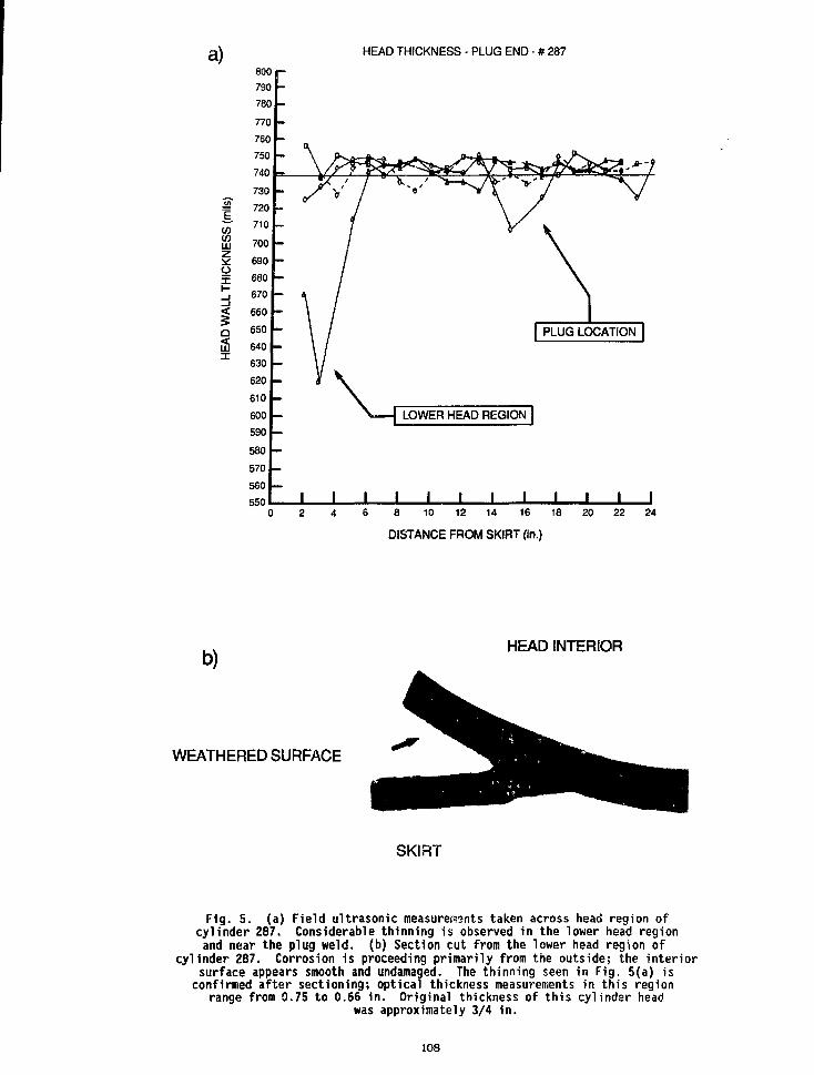
a) HEAD THICKNESS - PLUG END - # 287
LU
O
<LU
6 8 10 12 14 16 18
DISTANCE FROM SKIRT (in.)
b)HEAD INTERIOR
WEATHERED SURFACE
SKIRT
Fig. 5. (a) Field ultrasonic measurements taken across head region ofcylinder 287. Considerable thinning is observed in the lower head regionand near the plug weld, (b) Section cut from the lower head region of
cylinder 287. Corrosion 1s proceeding primarily from the outside; the interiorsurface appears smooth and undamaged. The thinning seen in Fig. 5(a) is
confirmed after sectioning; optical thickness measurements in this regionrange from 0.75 to 0.66 in. Original thickness of this cylinder head
was approximately 3/4 in.
108

Fig. 6. Cylinders in storage at K-1O66-K cylinder yard. Regions whereaccelerated corrosion attack might be anticipated are (a) lower head region,(b) areas in which dissimilar metals are in contract, (c) weld regions, and(d) areas where the cylinders rest on saddles. These regions are indicated
with arrows.
109
CYLINDER YARD INSPECTIONS
Periodic visual inspections of the cylinder yardsare to be supplemented by field metallography andultrasonic testing on a statistically determinedsampling of the cylinders. The field testing willemphasize those regions of the cylinders that havebeen identified for special attention.
Commercial E/R corrosion probes fabricated fromA516 cylinder steel will be placed in the cylinderyards, and corrosion rate measured frequently.These commercial probes will give promptnotification of any change in environmentalconditions leading to a major alteration incorrosion rate.
Inspection data will be entered into the data basedescribed below.
DOCUMENTATION
A data base has been established following theguidelines set forth in ANSI/ASME NQA-1 BasicRequirement No. 17 - Quality Assurance Records.Data is entered in commercial dBase III spreadsheetformat; and the data base is to be maintained usingIBM-compatible personal computers. Cylinder manu-facturing data, service history, and inspectionrecords are included; records are flagged forcylinders identified through either inspection orhistory as requiring special handling.
SUMMARY
Tails cylinders in outside storage at ORGDP arecorroding at rates which give a finite storage lifeas ASME code-qualified pressure vessels. Generalcorrosion rates are estimated at less than2 mils per year yielding a service lifetimeanticipated at more than 50 years; however,cylinder areas where accelerated attack might beexpected have been identified through (a) cylinderyard history and (b) examination of cylinders whichhave seen extended service, for special attention.
Field ultrasonic and metallography techniques havebeen developed for cylinder examination; periodicinspection (based on statistical sampling) of thecylinder yards at ORGOP is planned, using thesetechniques. A corrosion monitoring program for theOak Ridge yards, based on ASTM procedures and usingenvironmental corrosion test coupons, is under way.Documentation of cylinder condition will beprovided through an IBM PC-based records system,using commercial software, and conforming toANSI/ASHE NQA-1 standards. The program is intendedto assure that corrosion of these cylinders atORGDP never reaches the point where the cylinderscannot be safely transported or pressurized fortransfer.
REFERENCES
1. Uranium Hexafluoride Handling Procedures andContainer Criteria, 0R0-651, Rev. 5, Sept. 1987.
2. Alderson, J. H., Remaining Life of UF$ TailsCylinders, in publication.
3. Fortune, M. B. and Green, C. H., tffg CylinderTesting, KY-498, 1965.
4. Ritter, R. L., Oak Ridge Gaseous DiffusionPlant, personal communication to H. H. Henson.
5. Barber, E. J., Oak Ridge Gaseous DiffusionPlant, personal communication to H. M. Henson.
6. Kimmerly, E. Y., Oak Ridge Gaseous DiffusionPlant, personal communication to J. 0. Dodson,October 27, 1982.
7. Ziehlke, K. T., Oak Ridge Gaseous DiffusionPlant, personal communication to J. 0. Dodson,October 28, 1982.
8. Barlow, C. R. and Ziehlke, K. T., RuptureTesting of UFg Transport and Storage Cylinders,K-2059, in publication.
The submined manuscript has been authored by acontractoroltheU S.Government underConrract NoDE-AC05-8dOR2i«00 According*- the U SGovernment retains a nonexclusive, royalty-freelicense to publish or reproduce the published form ofthis contribution, or allow others to do so. tor U SGovernment Purposes
no

OVERVIEW OF THE FIVE-INCH PRODUCT CYLINDER
Ronald E. DomingScientist Specialist
Martin Marietta Energy Systems, Inc.Portsmouth Gaseous Diffusion Plant
Piketon, Ohio, USA
ABSTRACT
Model 5A and 5B cylinders are used for transporta-tion and storage of very highly enriched UF6product (VHE). The cylinders are manufacturedfrom 5-inch, schedule 40 pipe with welded pipe capcylinder heads. The Model 5B cylinder design hasonly recently been approved and has been includedin ORO-651, revision 5, and the 1987 revision ofANSI Standard N14.1. The basic difference betweenthe two models is that the Model 5A is fabricatedfrom Monel, while the 5B is fabricated fromnickel. A potential materials problem was iden-tified with the Model 5A cylinder and resulted ina modification to the existing Model 5A cylinders.The operating history, including the cause of thechange in the Model 5A design, results of recentproof testing, and the current cylinder specifica-tions are discussed.
INTRODUCTION
The five-inch diameter product cylinder wasdesigned to address nuclear criticality con-siderations for UF« enriched to greater than 30%U-235, as well as to assure materials com-patability with UF«. The nominal five-inchdiameter cylinder is an "always safe" geometry,and in use a minimum spacing between cylinders ismaintained (24 inches center-to-center) to furtherensure nuclear criticality safety. The five-inchproduct cylinder was designed to meet or exceedthe design requirements of the ASME Boiler andPressure Vessel Code, Division I, Section VIIIpertaining to pressure vessels even though the
cylinder did not fall under the jurisdiction ofthe code. The physical design standards for thecylinder are given in Table 1.
TABLE 1 STANDARDS FOR THE FIVE-INCH CYLINDER
DiameterOverall LengthVessel Length
Wall ThicknessMinimum VolumeDesign Pressure
InternalExternal
Hydrostatic TestPressure
5 Inches (12.7 cm)35.6 Inches (90.5 cm)29.5 Inches (74.9 cm)0.25 Inch (0.6 cm)0.284 Cubic Feet (8.04 1)
200 PSI (1.38 MPa) at 250°F22 PSI (0.15 MPa) at 250°F15 PSI (0.10 MPa) at -120°F
400 PSI (2.76 MPa)
The cylinders receive a hydrostatic pressure testat the manufacturing facility, and are alsorehydro tested every five years or upon emptyingif used for storage longer than five years. Threecylinder designs -- designated Model 5A, Model 5AModified, and Model 5B -- have been utilized sincethe 1950s. The difference between these designsis tne materials of construction which are givenin Table 2.
The Model 5A cylinder is constructed of Monel 400(70% Ni - 30% Cu); similarly, the Model 5AModified is Monel 400 except the valve couplingsor valve bosses are nickel. The Model 5B isconstructed of nickel with Monel 400 trim(handles, foot ring, neck ring, etc.).
TABLE 2 MATERIALS OF CONSTRUCTION FOR THE FIVE-INCH CYLINDERS
Description
ShellHeadsCouplingsNeck RingFoot RingDip PipeSupport RingHandlesValve Protector
Model 5A
Ni-Cu, ASTM B-165Ni-Cu, ASTM B-165Ni-Cu, ASTM B-165NI-Cu, ACTM B-165NI-Cu, ASTM B-165NI-Cu, ASTM B-165NI-Cu, ASTM B-165NI-Cu, ASTM B-164Carbon Steel
Model 5A Modified
Ni-Cu, ASTM B-165Ni-Cu, ASTM B-165Ni, ASTM B-161Ni-Cu, ASTM B-165Ni-Cu, ASTM B-165Ni-Cu, ASTM B-165Ni-Cu, ASTM B-165Ni-Cu, ASTM B-165Carbon Steel
Model 5B
Ni, ASTM B-161Ni, ASTM B-161Ni, ASTM B-161Ni-Cu, ASTM B-165Ni-Cu, ASTM B-165Ni-Cu, ASTM B-165Ni-Cu, ASTM B-165Ni-Cu, ASTM B-164Carbon Steel
111

MODEL 5A
The Model 5A cylinder was designed and procured inthe early 1950s for the handling of highlyenriched UF6. The material of construction (Monel400) was selected for its excellent corrosionresistance to fluorinating materials a? well asfor its resistance to atmospheric corrosion. Thiscorrosion resistance provided a container whichwould not consume the product or result in exter-nal corrosion thereby altering the tare weightand/or reducing container integrity. Two problemshave been identified with the Model 5A cylinders.The firit problem was encountered in the mid 1960swhen a customer was using empty cylinders as coldtraps for niobium pentafluoride, a use outside thedesign service conditions. During this servicethe Monel 400 cylinder developed stress corrosioncracking. The customer was informed of the damageto the cylinder, and the cold trapping of thiscompound was discontinued.
The second problem was more serious and resultedin a modification to the Model 5A cylinder. Inthe early 1970s, routine inspection of the cylin-ders revealed valve coupling (boss) cracking.This cracking was investigated and determined tohave been caused by liquid metal penetration ofthe grain boundaries, resulting in embrittlementand grain boundary cracking. The embrittlingagent was the silver solder used in the brazing ofthe cylinder valve into the cylinder. The in-vestigation also indicated that the embrittlementand cracking occurred during valve replacement andnot during initial valve installation. Duringvalve replacement the boss area is heated to thesilver solder liquidus temperature, the old valveremoved, the area cooled, the boss inspected, anda new valve inserted and brazed in place. Theheating of the boss to the brazing temperaturepermitted residual silver solder from previousvalve installations to penetrate the Monel 400grain boundaries which is a cracking mechanism forthis material. This problem resulted in a changein boss material from the original Monel 400 tonickel as explained below.
MODEL 5A MODIFIED
To accomplish the boss material changeout in the5A cylinders, a program was instituted in the1970s to systematically replace the valve bossesat the time of cylinder maintenance or duringroutine hydrostatic retesting. The resultingcylinders were termed Modified Model 5A or Model5A Modified. To date, all Model 5A cylinders inthe normal product flow cycle have been convertedto the Model 5A Modified specification.
The cylinder modification was designed to meet orexceed the requirements of the ASME Boiler andPressure Vessel Code, Version I, Section VIII (the
"Code"). However, at the time of the modifica-tions the Portsmouth facility did not hold a "CodeStamp," and therefore the modified Model 5A cylin-ders were not coded pressure vessels. This facthad very little impact upon the use of the cylin-ders, and the cylinders were subsequently listedin the two governing documents for UF6 cylinders:0R0 651, "Uranium Hexafluoride-Handling Proceduresand Container Descriptions," and ANSI N14.1,"American National Standard for Packaging ofUranium Hexafluoride fjr Transport." However,recently drafted regulations from both nationaland international agencies governing the shippingof UF6 have brought under scrutiny the voided"Code Stamp" on the Model 5A Modified cylinders.An extensive investigation into the fitness forservice of the modified cylinder was thereforeundertaken.
The investigation focused on demonstrating thatthe cylinder modifications met the intent of thecode and that cylinder integrity had not beencompromised. An engineering study encompassingdesign calculations, review of modification pro-cedures, and proof testing (hydrostatic pressuretesting) of three cylinders was performed toverify the integrity of the Model 5A Modifiedcylinders. The study concluded that the modifica-tion to the Model 5A cylinder did not affectcylinder integrity based on its demonstratedreliability in the field for up to twelve years,acceptance of the modification procedures by the"National Board of Boiler and Pressure VesselInspectors," and the proof testing results. Thehydrostatic pressure test results for threemodified cylinders were compared to a result of asimilar test performed in the 1960s prior to themodification. The rupture pressures were con-sidered similar for all four tests and are shownin Table 3. Failure mode and location were alsosimilar.
In late 1981 and early 1982 five of the Model 5AModified cylinders were found to have surfacecracks on the cylinder head (near or adjacent tothe head-to-boss weld) and also apparent weldinterface cracks. The weld failure mode was lackof fusion on the valve boss-to-cylinder head weldcaused, in part, by the use of a nickel weldingelectrode instead of the specified Monelelectrode. The cylinder head cracking failuremode was similar to that of the Model 5A valveboss cracking noted in the early 1970s. Inmodifying the Model 5A cylinders, the silversolder from the brazing of the valve had run downthe side of the nickel valve boss and penetratedthe Monel 400 cylinder heads. The silver solderthen embrittled the Monel 400 which resulted inthe cracking of the cylinder heads. In an effortto eliminate the silver solder embrittlementfailure mode, the Model 5B cylinder was designed.
TABLE 3 PROOF TEST DATA FOR 5A MODIFIED CYLINDERS
CylinderType
5A5A Modified5A Modified5A Modified
ModificationDate
NA198619791977
WallThickness
i" (0.6 cm)i" (0.6 cm)i" (0.6 cm)i" (0.6 cm)
RupturePressure
8250 psi (56.7 MPa)7950 psi (54.8 MPa)7200 psi (49.6 MPa)8600 psi (59.3 MPa)
% VolumeIncrease
212123
112

MODEL 5B
The design of the Model 5B UF, cylinder was com-pleted in 1983 and presented to the MartinMarietta Energy Systems, Inc., three-plant,UF, Cylinder and Cylinder Valve SpecificationCommittee. The cylinder is identical to the Model5A and 5A Modified cylinders in dimensions (Ref.Table 1). The only difference between the twocylinder designs is that the Model 5B shell andhead are constructed of nickel instead of Monel.This cylinder is subject to the same testing andquality assurance measures as the other five-inchcylinder designs; it has been procured as a"Coded" pressure vessel and is being phased intoroutine use for handling enriched UFt. The Model5B design has been included in 0R0 651, Revision 5and presented to the ANSI N14.1 Committee forincorporation into the 1987 Standards edition.
CURRENT STATUS
The five-inch product cylinders in use at thistime are restricted to the Model 5A Modified and
Model 5B designs. Almost all of the originalModel 5A cylinders have been reworked. The fewModel 5A cylinders in use are being used forextended storage and have not been emptied sincethe modification program was initiated. Of thefive-inch cylinders presently in service, 148 areof the Model 5B design which were procured in1983-1984. Currently, 250 Model 5B cylinders areon order, with another 250 to be procured in 1989at which time all off-site product shipments willbe made using Model 5B cylinders. The remainingModel 5A Modified cylinders will then be limitedto on-site UF, transfer and storage. To date, theModel 58 cylinder has been in service for four tofive years, and, based on this limited operatingexperience, has demonstrated satisfactory operat-ing performance. A fabrication procedure used toinitially install the valves in some of thesecylinders has been tentatively identified (at thetime of the writing of this paper) as causing bosscracking during revalving of these cylinders. Theresults of this investigation will be discussedwhen the paper is presented.
Praparad by Iha Portsmouth Gasaous Dlfluilon Plant.Piketon. Ohio 45661. oparalad by MARTINMARIETTA ENERGY SYSTEMS. INCORPORATED,lor tha U.S. DEPARTMENT OF ENERGY, undarContract No. DE-AC05-7EOR0000V
Tna submhad manuscript h»> baan author*! by acortractor ot Iha U.S. Govammant undai Conftad No.DEAC05-76OR00001. Accordingly, tha U.S.Govarnmant retains a nonaxduslva. royaky-traeIbanta 10 publish or raproctiKa Iha pubHshad form otthis conlrbution. or ajlow othars to do so. tor U SGovernment Purposas.
113

MAXIMUM CYLINDER FILL LIMIT EVALUATION
D, C. MasonMartin Marietta Energy Systems, Inc.
Paducah Gaseous Diffusion PlantPaducah, Kentucky
ABSTRACT
The maximum fill limit for the variety ofcylinders used by DOE and the remainder of thenuclear Industry 1s a key element In maintaining asafe and efficient operation. The fill limits arebased on several Important parameters. Thesefactors are discussed 1n the report along with therationale utilized and the conservatism provided.
INTRODUCTION
The nuclear industry utilizes a wide variety ofcylinders designed specifically for the safehandling and transport of UF6. The cylinders aremanufactured to strict engineering specificationswhich are developed with close regard to theproperties of UFS. The cylinders range from thevery small laboratory container designed forhandling gram quantities of UF6 to the large48-Inch diameter containers for use in shippingand handling up to 14 standard tons of UF6. Eachcylinder and each cylinder design have uniquecharacteristics and anomalies which limit themaximum quantity of UF6 to be withdrawn Into thecylinder. The maximum quantity of UF6 which canbe safely contained In a cylinder 1s based onseveral parameters and was developed to Insuresafe handling during typical in-plant activitiesas well as routine transportation requirements.The paper which follows examines each of theparameters, exhibits the conservatism providedwithin each of these parameters, and shows how theparameters are used 1n determining maximum filllimits. Additionally, recent modifications tofill limits will be examined along with therationale for the changes.
DEVELOPMENT OF CYLINDER FILL LIMITS
The requirement for establishing maximum filllimits for UF6 cylinders 1s obvious; personnelsafety. The characteristics of UF6, especially
Praparad by ma Paductfi Oataout OKtutfon Plant.Paducah. K M u t t , 42001. opaMad by MARTINMARIETTA ENERGY SYSTEMS. INCORPORATED,tor Ola U.S. DEPARTMENT OF ENERGY, undarContract No. DE-AC05-840R21400.
Tha lUbmktad manuscript hat baan authorad by acontractor ot ths U.S. Govammant undar Contact No.OE-AC05-MOR21400. Accordingly, tha U.S.Govarnmant ratalns a nonaxclutlva. royaRy-traalicanta to pi£Akh or raproduca ttia pubHthad form otthis contribution, or aJbw othan to do to, tor U.S.Govammant Purpotat.
density and coefficient of expansion, In additionto the hazards must be recognized. Safety must beattendant 1n all phases of the operation whether1t be feeding, filling, or shipping. Safety 1sthe key directive which governs both design andoperation. A flaw 1n a cylinder design, anoverfilled cylinder, an overheated cylinder, or acylinder containing excess volatile compounds canall lead to disaster, an occurrence not desiredwith the current sensitive world environment. Theprocedures and practices for safe handling of UF6have evolved by the interaction of many companiesand countries. Consistency within most countriesexists, however, commonality between countriesfrequently surfaces differences 1n rationale usedto develop the gu1del1.es. The IAEA Is pursuingthe possibility of common International policies.Shipper and receiver rationale must be equitableto allow a continuation of the Internationalnuclear Industry.
The primary and most widely used documentation formaximum cylinder fill limits, in addition to manyother related topics, has been ORO-651, "UraniumHexafluoride: Handling Procedures and ContainerDescriptions," and ANSI N14.1, "UraniumHexafluoride-Packaging for Transport." TheDepartment of Energy (DOE) document ORO-651 hasbeen compiled and Issued based on the extensiveexperience at the DOE facilities. The latestrevision of this document was issued duringSeptember 1987. Although the original Intent ofthe document was for U. S. Government use, theaudience has been expanded to an Internationalscope.
The ANSI N14.1 document has also been recentlyrevised (October 1987) to include several changesin Industry practices. Initially Issued In 1971as the private Industry version of ORO-651, thisdocument was developed with internationalparticipation around the framework provided byORO-651. Both documents are currently viewed ascomplements. The tables, in fact, in both ORO-651and ANSI N14.4 regarding maximum fill limits arevirtually Identical. Therefore, the basis forinternational consistency of maximum fill limitshas been established. But what parameters areevaluated to determine the maximum amount of UF6which can safely be withdrawn into a certaindesign or size cylinder? Each of these parameterswill be explored in detail in the next section.
115
PARAMETERS AFFECTING FILL LIMITS individual cylinder had a unique maximum limit.
There are four parameters, 1n addition to standardUF6 characteristics, which govern the maximumcylinder fill limit. These are 1) cylindervolume, 2) maximum cylinder design temperature, 3)purity of the UF6 and 4) safety factor or "FreeVolume" desired in the containment. These itemsare not listed 1n priority order since all areintegral and essential ingredients 1n thedetermination process. By discussing each of thefactors independently, then collectively, theconservatism designed into the fill limits willbecome very apparent.
The initial factor to be discussed is the volumeof the cylinder. Cylinder design and procurementspecifications for all cylinders purchased for DOEfacilities require, among other requirements, aminimum internal volume. The actual volume, whichis greater than the minimum in virtually everycase, is certified by evaluating the capacity ofthe cylinder by filling the vessel with water,weighing, and correcting to the standardtemperature of 60 degrees Fahrenheit. The DOEfacilities have employed, over the years, the useof both certified and non-certified cylinders. Atthe present time, only certified cylinders areused in shipments from DOE facilities and the useof cylinders containing non-cert1f1ed volumes isstrictly minimized.
The comparison of the actual cylinder volumes tothe minimum specifications is appropriate todetermine the average "additional" volumeavailable for UF6 residence. Two widely usedcylinders were chosen as candidates to exhibit thecomparison; the Model 48X 10-ton cylinder and theModel 48G 14-ton cylinder. The evaluation wasconducted at the Paducah. Gaseous Diffusion Plantby collecting data in a random fashion fromcylinders 1n service. The model 48X cylinderswere constructed in the early 1950s and arecurrently used to transport enriched productbetween facilities. The minimum specificationcylinder volume is 108.9 cubic feet. The samplingof 83 cylinders revealed an average volume of112.06 cubic feet or the existence of more than3.0 cubic feet (2.9 percent) additional volumeover that used in maximum fill limit calculations.
The model 48X cylinders were all constructed tothe identical specification and showed theexpected cylinder-to-cylinder variation. TheModel 48G cylinders, as a further example, wereconstructed to similar specifications and bynumerous fabricators. Three separate samplingswere conducted at Paducah involving 53 cylinders.The average certified volume in each of the threesamplings was 143.70, 143.86, and 144.06 cubicfeet. While the averages are remarkably similar,the lowest value found in any of the 53 cylinderswas 139.82 cubic feet, still well above theminimum of 139.0 cubic feet.
The conclusion to be reached from this singleparameter is that significant conservatismrelative to safe fill limits exists in cylindervolume alone. Why not use the actual volumt fordetermining maximum fill limits? The minimumvolume is standard for each cylinder type,provides a consistent limit for each type and use,and minimizes errors that could exist if each
The next parameter which has an effect on themaximum limit 1s the maximum cylinder designtemperature. While the term implies a mechanicalor structural limit, the maximum actually refersto the operating temperature of the UF6. The termmaximum design is to be considered synonymous withmaximum operating for the balance of the report.The coefficient of expansion of UF6 between thesolid and liquid phases is extremely high and anoperating temperature above the maximum allowablecould cause the expanding liquid to completelyfill the Internal volume of the cylinder andcreate hydraulic forces. The forces could exceedthe structural yield value for the cylinders 1fthe temperature was allowed to Increase further.A violent explosion could result from anuncontrolled heating of a cylinder containing UF6.
The maximum design temperature for the heavy-wallcylinders is typically 250 degrees Fahrenheit andthe maximum design temperature for most of thelight-wall cylinders 1s 235 degrees Fahrenheit.It must be mentioned at this point that some ofthe light-wall cylinders constructed during the1950s and early 1960s were catalogued with amaximum cylinder design temperature of 300 degreesFahrenheit although this temperature was neverapproached at a DOE facility.
The percent of the available volume to be occupiedwhen a specific quantity of solid UF6 is heated toa liquid in a closed cylinder is a direct functionof temperature. If the temperature is Increased,the liquid expands further and occupies anincreased volume. If the temperature 1s reduced,the converse is true. The maximum cylinder filllimits are constructed by using these maximumtemperatures. In actual operating practice atvirtually all DOE sites where solid UF6 1svaporized and/or liquefied, the highesttemperature reached 1s substantially below thismaximum. Once again, this provides an additionalmeasure of conservatism. The typical temperaturewill range from a low value of just over 200degrees Fahrenheit to about 225 degreesFahrenheit. These lower temperatures will reducethe volume the liquefied UF6 will occupy byapproximately three percent.
A quantification of the above scenario can beconstructed by using a cylinder containing 25,000lbs. of UF6. The UF6, when heated to 250 degreesFahrenheit, will occupy additional cubic feet whencompared to the same quantity heated to only 225degrees Fahrenheit. The reduction in thetemperature (maximum versus typical operating)consists of a conservatism factor of over threepercent. Why not use the typical operatingtemperature? While DOE sites maintain a lowertemperature, other UF6 handling facilitiesroutinely approach 235 degrees Fahrenheit toattain required flow rates. Therefore, it isconsidered prudent to establish a consensus value,in this case the maximum design temperature, onwhich to base maximum fill limits. Additionalsafety can be obtained by lowering operatingtemperatures. The maximum design temperature andthe certified water weight capacity are stamped oneach cylinder nameplate.
116
Various chemicals are present 1n UF6 asImpurities. The concentration of these lowmolecular weight compounds has been exploredtheoretically and relationships established.These low molecular weight compounds are morevolatile than UF6 and can be found 1n both theliquid and the vapor phase as a cylinder 1s beingheated. The impurities in the UF6 afterwithdrawal from the gaseous diffusion process aretypically found to be air components, oxygen andnitrogen, refrigerant, various fluorides and HF.The isotopic enrichment process will cause thelighter weight gases to move toward the productwithdrawal segment of the plant. A portion ofthese materials will be withdrawn into productcylinders. The tails withdrawal stream,containing the greater portion of the heavierdepleted uranium isotopes, will be void of anysignificant concentrations of the Impurities.
The maximum fill limits documented in both 0R0-651and ANSI N14.1 are based on a minimum purityfactor of 99.5 weight percent UF6. This providesfor a maximum impurity of less than one-halfpercent in all cascade material streams, Includingtails and product. The DOE diffusion plantsconduct routine uranium, isotopic andradiochemical measurements on these streams todetermine the quality of the material, includingpurity. The results of the evaluation procedurefor FY 1987 are summarized as follows:
Stream Number of Results (wt.% UF 6)Analyzed Samples Average Range
Product
Tails
31
26
99.973
99.976
99.95-100.0
99.95-100.0
The final parameter which has a significant impacton the magnitude of UF6 which can be safely placedin ? cylinder is the safety factor or "freevolume." This factor has been discussed to adegree in the purity section and 1s defined as aspecific percentage of the minimum internal volumeof the cylinder. The volume is provided to allowresidence space for light gases and/or additionalexpansion room for UF6 1f needed and is the onlyone of the parameters which 1s operator variable.
The safety factor was originally defined as fivepercent of the minimum internal volume of thecylinder at the maximum design temperature of 250degrees Fahrenheit for heavy-wall cylinders. Thefactor was reduced to three percent at the 235degree Fahrenheit level for the light-wallcylinders to be used for long-term storage oftails material. This distinction recognizes theslight difference 1n purity when comparing productand tails. Recent changes 1n the fill limitrationale have Increased the safety factor to fivepercent for the light-wall cylinders. The Ught-wall cylinders are typically used for transportingand storage of depleted material, which 1sinherently purer, and require less "free volume."The Increase 1n the safety factor simply Increasesthe confidence in the use of the cylinders, butalso allows the overall fill limit rationale to bemore consistent: five percent safety factor(based on the minimum cylinder volume) at themaximum design temperature of the cylinder.
A review of the four key parameters affecting thedetermination of maximum cylinder fill limitsshows a consistent rationale which has beenadopted Internationally. Each of the factors hasbeen determined In such a manner to yield aminimum of a five-percent margin of safety. Thisprovides limits which are moderately "forgiving"in daily operating scenarios; but are based onfactual evidence.
The calculations determining the maximum filllimits for UF6 cylinders have assumed the presenceof up to one-half percent impurities and haverequired the availability of ampie void space forresidence of these gases during the heating cycle.The general assumption has been to consider nosolubility of the gases in UF6. In actuality, asa cylinder Is being heated for vaporization orliquefication, the impurities contained within thevoid space above the solid UFS will be compressedonly a slight amount. The compressibility factorand solubility of the gases has been establishedthrough testing and analytical evaluation. Thefurther heating of the UF6 will cause an increasein the rate at which the light gases condense andreenter solution with UF6.
The FY 1987 data 1n the table above 1s typical formaterial withdrawn from the Paducah cascade. Areview of previous years will provide similarresults and verify that the purity of UF6 productor tails from the diffusion plants is extremelyhigh. Although the fill limit calculation allowsfor a maximum of one-half percent Impurities, theactual percent of Impurities present 1n cylindersis, under the most pessimistic conditions, onlyten percent of this value. Therefore, the voidspace available for light gases or impurities hasbeen overstated, yielding conservatism andadditional space for UF6 expansion.
COMPARISON OF LIQUID AND SOLID FILL LIMITS
The fill limit evaluation is designed to be ofassistance either while a cylinder 1s beingfilled, fed, or transferred. But how does thisrationale apply when the UF6 has solidified andthe cylinder has been prepared for shipment?
A cylinder containing liquid UF6 should be handledonly the minimum amount necessary to place thevessel into appropriate saddles forsolidification. Liquid cylinders are nottransported on standard conveyances over the road;only cylinders containing solid UF6. The elevatedrisk and danger is present while the UF6 is 1nliquid form. Therefore, the maximum fill limits,as well as other restrictions, should be developedaround this segment of the operation. Then, asthe material solidifies, the shipper and receivercan be well assured of a cylinder which is safeunder routine operating and shipping conditions.
The only credible scenario in which a cylindercontaining UF6 would be a hazard during transportis to Involve the cylinder 1n a major fire duringan accident. The cylinder would have to beengulfed in the uncontrolled heat source for asignificant period of time. There have been noaccidents Involving material in transit from a DOEfacility 1n which a fire has engulfed the cylinder
117
causing a hydrostatic rupture. There have been noactual scenarios anywhere in the world in whichthis has happened. Therefore, no specialprecautions need be applied for transportation ofL)F6 although some organizations are consideringthe use of overpacks for routine shipments of allmaterial for safety purposes in addition tocriticality. A conservative maximum fill limitdeveloped with regard to liquid UF6 will providean equally conservative condition for a cylindercontaining solid UF6. Until April 1986, there hadnever been a limit expressed on the percent of thecylinder volume which could be occupied by solidUF6. At that time, a Notice for ProposedRulemaMng was issued by the U.S. Department ofTransportation which would limit the occupiedvolume of solid UF6 at 68 degrees Fahrenheit to 61percent. The value was developed by convertingthe maximum fill limit for Models 48X and 48Y, aspresented in ORO-651, to a percent of internalvolume by use of the density o: UF6 at 68 degreesFahrenheit (317.8 Ib/ft3). The calculated volumeof UF6 was then compared to the minimum acceptablevolume for the cylinders to yield a value ofapproximately 61 percent. By strict applicationof the DOT regulation, the majority of DOE light-wall cylinders filled with tails material havebeen rendered non-shippable without the initiationof drastic action. This action would be to heatcylinders and vaporize or liquid transfer aportion of the material from the cylinders. Therisks associated with this action far outweigh theshipping of the cylinders containing solid UF6occupying greater than 61 percent.
How do the parameters previously mentioned reallytranslate into shipping limits? The applicationof the parameters discussed earlier allow forreasonable and safe shipping limits. The twoprimary limits are as follows:
• Cylinders with a maximum design temperature of250 degrees Fahrenheit
- Require five percent safety volume
- Density of UF6 :
P 250 degrees Fahrenheit = 203.3 lb/ft3
P 68 degrees Fahrenheit = 317.8 lb/ft3
- Occupied volume =
203.3 x .95 = 60.77% volume317.8
This calculation yields a volume very similar tothe value determined by DOT, although with a morefirm analytical basis.
• Cylinders with a maximum design temperature of235 degrees Fahrenheit
Require five percent safety volume
- Density of UF6 :
<a 235 degrees Fahrenheit = 207.1 lb/ft3
@ 68 degrees Fahrenheit - 317.8 lb/ft3
- Occupied volume =
207.1 x .95 = 61.91% volume317.8
While the second calculation exceeds the DOTregulatory limit, it is based on realisticparameters not included by DOT. In an effort toresolve the Issue, DOE has petitioned DOT throughpriority and emergency exemptions to accept a 62percent value for the lower temperature(light-wall) cylinders.
RECENT NATIONAL AND INTERNATIONAL ACTION ONMAXIMUM FILL LIMITS
Several recent modifications have been made tocylinder fill and shipping limits. These changesare documented in both ORO-651 and ANSI N14.1 -1987.
The ORO-651 guideline listed on the "UF6 CylinderData Summary" states:
For DOE gaseous diffusion plant tails with UF6purity In excess of 99.5% the shipping limit is28,000 lbs. for cylinders with 8,880 lbs. watercapacity or greater (142.35 cubic feet).
In like manner, ANSI N14.1 - 1987 states:
Fill limits (for cylinder Models 48T, 480,480M, 48H, 48HX, and 48G) are based on 235degrees Fahrenheit maximum UF6 temperature andminimum UF6 purity of 99.5 percent. Theallowable fill limit for tails UF6 with aminimum purity of 99.5 percent may be higherbut shall still not result in a cylinder ullageof less than five percent when heated to thecylinder design temperature of 235 degreesFahrenheit based on actual certified volume.
Each of the statements 1s equivalent and supportsthe position established in this paper. Theexcerpts from both ORO-651 and ANSI N14.1-1987 arebased on conditions surrounding the filling of acylinder with liquid UF6; however, as statedpreviously, the resulting volume occupied by theUF6 after solidification will also be acceptable.
CONCLUSION
The development of maximum fill limits for l)F6cylinders has been completed and documented bothnationally and Internationally. The limits havebeen modified recently to include new Informationpertaining to certain cylinder types. Theevaluations have recognized the key parameterswhich have an effect on the validity of thelimits, while establishing a firm foundation Insafety. The primary factors include minimum/actual internal cylinder volume, maximum/actualoperating temperatures, high purity of thediffusion plant UF6 and the maintaining of anadequate safety or "free" volume. By utilizingthese factors, maximum fill limits can beconstructed for consistency and safety. Thelimits were developed around the filling ofcylinders with liquid UF6 and have resulted inrealistic limits based on consistent rationale. Avery conservative maximum fill limit for liquidUF6 conditions will result in equally conservativevolume occupancy limits for solid UF6.
118

OVERPACKS AND PROTECTIVE PACKAGINGFOR 30-INCH UF6 CYLINDERS
P. A. CraigManager* Marketing Government Contracts
Nuclear Packaging* Inc.1010 S. 336th Street
Federal Way. Washington 98003 U.S.A(206) 874-2235
ABSTRACT
The development and use of p r o t e c t i v e packagingoften referred to as overpacks for t ransport of30-Inch diameter uranium hexafluoride cylinders 1snot new. The generation of 21PF-1 and 21PF-2protective shipping packages developed under De-partment of Transportation (DOT) rules for aspecification package are currently s t i l l 1n use.However* problems developed with the 21PF's In1982 which led to a DOT proposed rulemaking InAugust 1984. Action to complete the rulemakinghas not been completed. However, a recently pub-l ished American National Standards I n s t i t u t estandard on Uranium Hexafluoride for Transport(1987) has placed greater emphasis on protect ivepackaging qua l i t y assurance and periodic Inspec-t ion. The chemical hazard of uranium hexafluoridehas also received recent attention by the Interna-t ional Atomic Energy Agency In thei r 1987 reporton "Recommendations for Providing ProtectionDuring the Transport of Uranium Hexaf1uoride".
Nuclear Packaging* Inc. (NuPac) recognized a needfor an advanced state of the a r t pro tec t ivepackage and designed* tes ted, obtained an U.S.Nuclear Regulatory Commission cer t i f ica te of Com-p l l a n c e and a DOT c e r t i f i c a t e of competentauthority for IAEA regulat ions. The designationof th is package Is the UX-30.
This paper w i l l discuss the UX-30 design consider-at ions, tes t ing approach used, and tes t resu l tsobtained which supported approval of the C e r t i f i -cate of Compllance by NRC.
Final ly , a recommendation Is made to complete theDOE proposed rulemaking and incorporate the re-vised ANSI N14.1 Standard-1987.
I. INTRODUCTION
The topic of th is paper 1s "Overpacks and Protec-t i v e Packaging for 30-Inch Uranium Hexaf luor ideCyl inders". The terms overpacks and protect ivepackaging are synonymous. I t 1s the outer pack-aging used to enclose cy l inders containing en-riched uranium Jiexafl uoride (UFg) exceeding 1weight percent U . A US Department of Transpor-tat ion Specification 21PF-1 pro tec t ive overpack(reference 1, 49 CFR 178.121) has been used 1n thetransport of Isotopical ly enriched UFg since about1968, during which time thousands of overpackshave been manufactured and placed Into serv ice.Photos of these overpacks 1n service 1n Japan,Europe and the United States are presented.
Approximately 85-90JB of the 21PF-ls are control ledby Japan and Europe, with the USA control l ing thebalance, or 10-15* (200 to 300 containers). I n -terest ingly enough, the Eastern block countries donot use overpacks. Soviet enriched UFg is sent toRiga by ra i l then loaded into overpacks for ship-ment elsewhere in Europe and to the USA.
There have been two foreign and two US manufact-urers of 21PF-1 overpacks: one 1n Germany, one inI t a l y and two US manufacturers. There Is oneact ive 21PF-1 manufacturer 1n the US today. UF6moves In worldwide commerce: Sweden, Japan,France, United Kingdom, Germany, and USA a l l haveconversion plants to covert UFg to uranium oxideand reactor fue l .
Three incidents In 1982 required rad io log ica lresponse forces to respond to apparent problemscaused by the inleakage of water to the 21PF-1overpacks. Several 21PF-ls were rejected fo rwater leakage, rot ted wood In the step j o i n t ,holes 1n the outer shel l * and rusting of the outershel 1 and structural members. Proper maintenanceof the 21PF-1 1s required. Lack of maintenance*design f laws and poor manufacturing pract icescreated potential safety problems - such as l i s tedIn Table 1.
Table 1
Current Safety Problems 21PF-1
Water Absorption (200 pounds plus)ModeratorDegraded mechanical propertiesSteam explosion in case of f i r eWet-freeze-thaw cycle effects
CorrosionDegraded mechanical propertiesThermal resistance in case of breached shell
Incomplete FoamingThermal resistanceEnergy adsorption
Not Made to SpecificationI t a l i a n sof t wood (end-glued small pieces)frame
Not Stamped with Tare WeightCannot determine water content
119
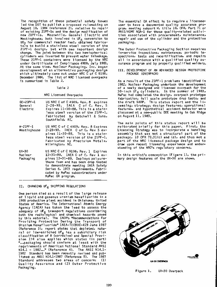
The recognition of these potential safety issuesled the DOT to publ ish a proposed rulemaking onAugust 10. 1984 (reference 2), re la t ive to repairof existing 21PF-ls and the design modification ofnew 21PF-ls. Meanwhile. General E l e c t r i c andWest1nghouse» both involved 1n UFg conversion toUO2 for commercial reactor f ue l , obtained fabrica-to rs to bu i l d a s ta in less steel version of the21PF-1 design* but with one important designchange. The j o i n t between the two hemisphericalcylinders was inverted to prevent water inleakage.These 21PF-1 containers were licensed by the NRCunder C e r t i f i c a t e of Compliance 4909, July 1983.At the same t ime. Nuclear Packaging, Inc. begandevelopment of an a l t e r n a t i v e packaging designwhich u l t i m a t e l y came out under NRC C of C 9196.December 1984. The l i s t of NRC licensed overpacksis summarized 1n Table 2.
Table 2
NRC Licensed Overpacks
GE-21PF-1 US NRC C of C 4909, Rev. 8 expiresGeneral 2-28-93. IAEA C of C, Rev. 5Electr ic Expires 11-30-88. This is a s t a i n -
less steel version of the 21PF-1.Fabricated by Getchel 1 4 Sons,Southfield, RI.
W-21PF-1 US NRC C of C 4909, Rev. 8 ExpiresWestinghouse 2-28-93. IAEA C of C, Rev 5 ex-
pires 11-30-88. This is a s t a i n -less steel version of the 21PF-1.Fabricated by Precis ion Metals,Wilmington, NC.
UX-30 US NRC C of C 9196, Rev. 1 ExpiresNuclear 12-31-89. IAEA C of C, Rev 1 ex-Packaging pires 12-31-89. Deploys po lyure-
thane foam and has been drop testedto demonstrate meeting IAEA SafetySeries 6, 1973 requirements. Fabri-cated by NuPac subcontractors underNuPac QA program.
The essential QA effect is to require a licensee-user to have a documented qual i ty assurance pro-gram, meeting subpart H, t i t l e 10, CFR, Part 71 orANSI/ASME NQA-1 for those qual i ty-re lated a c t i v i -t i e s associated with procurement, maintenance,repair and use of the cyl inder and the protectivepackaging.
The Outer Pro tec t ive Packaging Section requiresIn-service Inspections, maintenance, periodic i n -spections, tests and recer t l f i ca t ion, and repairsa l l in accordance with a q u a l i f i e d q u a l i t y as-surance program and by properly qual i f ied welders.
I I I . DEVELOPMENT OF AN ADVANCED DESIGN PROTECTIVEPACKAGE (OVERPACK)
As a r e s u l t of the 21PF-1 problems i d e n t i f i e d 1n1982, Nuclear Packaging undertook the developmentof a newly designed and licensed overpack fo r the30- inch UFg c y l i n d e r s . In the summer of 1983,NuPac had completed the design, overpack prototypefabr i ca t ion , f u l l scale prototype drop t e s t s , andthe d r a f t SARP. This s ta tus repo r t and the l i -censing, strategy, design features, operationalfeatures, and hypothetical accident behavior werediscussed at a non-public DOE meeting in Oak Ridgeon August 11, 1983.
The main points of th i s status report w i l l berei terated b r i e f l y for t h i s paper. F i r s t , theLicensing Strategy was to incorporate a handlingassembly that was not a s t ructura l part of thepackage, 10 CFR 71.31(c) and (d), and thus not apart of the NRC 1icensed package design and todraw upon recent licensing experience and under-standing of the NRC's regulatory concerns.
In t h i s a r t i s t ' s conception (Figure 1), the p r i -mary design features of the UX-30 are shown.
I I . CHANGING UF6 SHIPPING REGULATIONS
One person died as a resu l t of the large releaseof l i qu id and gaseous uranium hexafluoride in a1986 production plant accident in Oklahoma, UnitedStates of America. The International Atomic EnergyAgency (IAEA) has taken the lead to assess theadequacy of UFg transport regulations consideringboth the radiological and chemical hazards posedby this material. The IAEA's "Recommendations ForProviding Protection During the Transport ofUranium Hexafluoride" IAEA-TECDOC-423 June 1987(Reference 3), report states that depleted, natu-ral or low-enriched UFg has a subsidiary r iskclassif ication of 8 (corrosive) and Special Provi-sion 174 also applies which states ( in part)"...packaging should conform at least with therequirements of American National Standard ANSIN14.1 - 1982..." (Reference 4). The ANSI N14.1-1982 Standard has been recently revised and pub-lished as ANSI N14.1-1987 (Reference 5). The 1987Standard addresses two areas of concern: (1)Qua l i t y Assurance and (2) Outer P ro tec t i vePackaging.
UX-30 OVBVMCK
Figure 1 . UX-30 Overpack
120
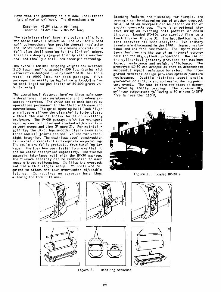
Note that the geometry 1s a c lean, unclutteredright circular cylinder. The dimensions are:
Exterior 43.5" dia. x 96" longInterior 31.0" d1a. x 82.75" long
The sta in less steel inner and outer she! Is formthe basic sidewall structure. The six inch closedce l l polyurethane foam provide thermal insulationand impact protection. The closure consists of afu l 1 c l am she! 1 opening for the 30-B cyl inders.There is a deepl y steeped l i d l i p w i th a weatherseal and f i n a l l y a bal l - lock sheer pin fastening.
The overal l nominal shipping weights are overpack2130 lbs., handling assembly 450 lbs. (varies withalternative designs) 30-B cylinder 6420 lbs. for at o t a l of 9000 l b s . f o r each package. F ivepackages can easily be hauled on a t ruck / t ra i le rto meet legal weight l i m i t s of 80,000 gross ve-hicle weight.
The operational features involve three main con-s iderat ions: Use, maintenance and tiedown as-sembly Interface. The UX-30 can be used easily byoperations personnel in the f i e l d with ease andconvenience. The quick openi ng bal 1 lock f lushpin closure al lows the clam she l l s to be closedwithout the use of t o o l s , bo l ts or aux i l i a r yequipment. The UX-30 package, with i ts transportsaddle, can be 1 i f ted and stacked with a minimumof work steps and time (Figure 2). For maintain-a b i l i t y , the UX-30 has smooth, c lean, even sur-faces and a l l j o i n t s are seal welded for watei—tight integri ty. The stainless steel constructionis corrosion res is tant and requires no paint ing.The seals are f u l l y protected from handling da-mage. The foam has been tested to prove that i thas no water absorption capabi l i ty . The tiedownassembly interfaces well with the UX-30 package.The tiedown assembly can be customized to userneeds without relicensing. I t l i f t s the overpackand l i d with a s ing le setup. No too ls are re-quired to attach the four over-center adjustablelatches. I t requires no spreader bar, thusallowing for fork l i f t use.
Stacking features are f l ex ib le ; for example, oneoverpack can be stacked on top of another overpackor a l i d of an overpack can be placed on top ofanother overpack, etc. There is an optional t i e -down using an ex is t ing bo l t pattern or chainbinders. Loaded UX-30s are carr ied f i v e to atruck t r a i l e r (Figure 3). The hypothetical acci-dent behavior has been analyzed. Two primaryevents are discussed in the SARP: impact res is -tance and and f i r e resistance. The impact resis-tance features are the use of an integral strong-back for the UFg cylinder protection. The use ofthe c y l i n d r i c a l geometry provides for maximumimpact resistance and weight e f f i c iency . Theprototype UX-30 was dropped 30 feet to demonstratesuccessful impact resistance behavior. The inte-grated membrane design provides optimum punctureresistance. Duct i le s ta in less steel she l l sguarantee no rupture and no tear ing during punc-ture events. The foam is f i r e resistant as demon-strated by sample tes t i ng . The maximum UFgcylinder temperature following a 30 minute 1475°Ff i r e is less than 150°F.
Figure 3. Loaded UX-30's
Figure 2. Handling Sequence
121
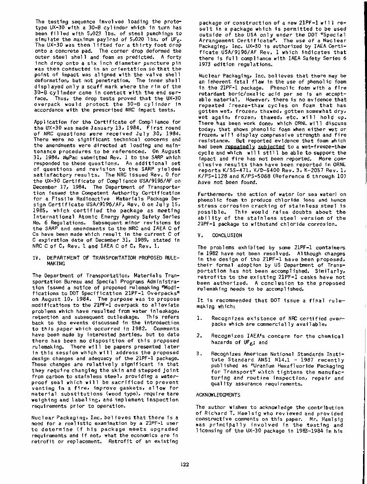
The testing sequence Involved loading the proto-type UX-30 with a 30-B cyl inder which in turn hasbeen f i l l e d with 5,023 lbs. of steel punchings tosimulate the maximum pay1 r i d of 5,020 lbs. of UFg.The UX-30 was then l i f t e d fo r a t h i r t y foot droponto a concrete pad. The corner drop deformed theouter steel she! 1 and foam as predicted. A fortyinch drop onto a s ix inch diameter puncture pinwas then conducted in an o r i en ta t i on so tha t thepoint of impact was aligned with the valve shel ldeformation, but not penetration. The Inner shel ld isplayed oniy a scuf f mark where the rim of the30-B cy l i nde r came in contact wi th the end sur-face. Thus, the drop tests proved that the UX-30overpack would protect the 30-B cy l i nde r inaccordance with the prescribed NRC impact tests.
Application for the Cert i f icate of Compliance forthe UX-30 was made January 13, 1984. F i r s t roundof NRC questions were received Ju l y 30, 1984.There were no s igni f icant technical concerns andthe amendments were directed at loading and main-tenance procedures to be referenced. On August31, 1984, NuPac submitted Rev. 1 to the SARP whichresponded to these questions. An add i t iona l setof questions and rev i s ion to the SARP y ie ldedsa t i s fac to ry r e s u l t s . The NRC Issued Rev. 0 forthe UX-30 Cert i f icate of Compliance USA/9196/AF onDecember 17, 1984. The Department of Transporta-t ion issued the Competent Authority Cert i f icat ionfor a F iss i le Radioactive Materials Package De-sign C e r t i f i c a t e USA/9196/AF, Rev. 0 on Ju ly 15,1985, which c e r t i f i e d the package as meetingIn te rna t iona l Atomic Energy Agency Safety SeriesNo. 6 Regulations. Subsequent minor revisions tothe SARP and amendments to the NRC and IAEA C ofCs have been made which resul t in the current C ofC expiration date of December 31, 1989, stated inNRC C of C, Rev. 1 and IAEA C of C, Rev. 1 .
IV. DEPARTMENT OF TRANSPORTATION PROPOSED RULE-MAKING
The Department of Transportation, Materials Tran-sportation Bureau and Special Programs Administra-t ion issued a notice of proposed rulenaking "Modi-f icat ions to DOT Speci f icat ion 21PF-1 Overpacks"on August 10, 1984. The purpose was to proposemodifications to the 21PF-1 overpack to a l l ev i a teproblems which have resulted from water inleakage,retention and subsequent outleakage. This refersback to the events discussed in the introductionto t h i s paper which occurred in 1982. Commentshave been made by interested part ies, but to datethere has been no d i spos i t i on of t h i s proposedrulemaking. There w i l l be papers presented la te r1n t h i s session which w i l l address the proposeddesign changes and adequacy of the 21PF-1 package.These changes are r e l a t i ve l y s igni f icant in thatthey require changing the skin and stepped j o i n tfrom carbon to stainless s tee l , providing a water-proof seal which w i l l be sac r i f i ced to preventvent ing in a f i r e , improve gaskets, a l low formater ia l subs t i tu t ions <wood type), require tareweighing and l a b e l i n g , and implement Inspect ionrequirements pr ior to operation.
Nuclear Packaging, Inc. bel 1eves tha t there is aneed for a rea l i s t i c examination by a 21PF-1 userto determine i f h i s package meets upgradedrequirements and i f not, what the economics are inr e t r o f i t or replacement. Retrof i t of an existing
package or const ruct ion of a new 21PF-1 w11 1 re -s u l t in a package which 1s permitted to be usedoutside of the USA only under the DOT "SpecialArrangement C e r t i f i c a t e " . The use of a NuclearPackaging, Inc. UX-30 is authorized by IAEA Cer t i -f i c a t e USA/9196/AF Rev. 1 which Indicates tha tthere 1s f u l l compliance with IAEA Safety Series 61973 edit ion regulations.
Nuclear Packaging, Inc. believes that there may bean inherent fata l flaw In the use of phenolic foamin the 21PF-1 package. Phenolic foam with a f i r eretardant bor ic/oxal ic acid per se 1s an accept-able material . However, there is no evidence thatrepeated freeze-thaw cycles on foam tha t hasgotten wet, f rozen, thawed, gotten somewhat dry,wet again, f rozen, thawed, e tc . w i l l hold up.There has been work done, which ORNL w i l l discusstoday, that shows phenolic foam when either wet orfrozen, w i l l display compressive strength and f i r eresistance. But reported evidence that foam whichhad been repaatedly subjected to a wet-freeze-thawcycle and which w i l 1 s t i l 1 be able to support theimpact and f i r e has not been reported. More con-c l u s i v e resu l t s than have been reported in ORNLreports K/SS-471, K/D-S400 Rev.3, K-2057 Rev. 1 ,K/PS-1128 and K/PS-5068 (Reference 6 through 10)have not been found.
Furthermore, the action of water (or sea water) onphenolic foam to produce chloride ions and hencestress corrosion cracking of s ta in less steel ispossible. This would raise doubts about thea b i l i t y of the s ta in less steel version of the21PF-1 package to withstand chloride corrosion.
V. CONCLUSION
The problems exhibited by some 21PF-1 containers1n 1982 have not been resolved. Although changesin the design of the 21PF-1 have been proposed,thei r formal adoption by US Department of Trans-por tat ion has not been accomplished. Simi lar ly,r e t r o f i t s to the ex is t ing 21PF-1 casks have notbeen authorized. A conclusion to the proposedrulemaking needs to be accomplished.
I t is recommended that DOT issue a f i na l r u l e -making which:
1. Recognizes existence of NRC cer t i f ied over-packs which are commercially avai lable,
2. Recognizes IAEA's concern for the chemicalhazards of UFg; and
3. Recognizes American National Standards I n s t i -tu te Standard ANSI N14.1 - 1987 recent lypublished as "Uranium Hexafluoride Packagingfor Transport" which t ightens the manufac-tu r ing and routine inspect ion, repair andqual i ty assurance requirements.
ACKNOWLEDGMENTS
The author wishes t o acknowledge t h e c o n t r i b u t i o nof Richard T. Haelsig who reviewed and providedconstructive comments on this paper. Mr. Haelsigwas p r i n c i p a l l y involved in the tes t ing andlicensing of the UX-30 package in 1983-1984 In his
122
ro les at Nuclear Packaging, Inc. cumulating as thePresident 1984-1987. The UX-30 design was createdby La r ry J . Hansen and John D. Kent a l s o o fNuclear Packaging. Inc.
REFERENCES
1 . Code of Federal Regulat ions. T i t l e 49 Parts178-199, T r a n s p o r t a t i o n , Sec t ion 49 CFR178.121, " S p e c i f i c a t i o n 21PF F i r e and ShockR e s i s t a n t , Phenol1c-Foara I n s u l a t e d , MetalOverpack
2 . Department of T ranspor ta t ion Proposed Rule-making, Modif icat ions to DOT Speci f icat ion21PF-1 Overpacks, Federal Register 49. No.160 Thursday, August 16, 3.984, ProposedRules. Docket No. HM-190, Notice No. 84-1,dated August 10, 1984
3. Recommendations for Providing ProtectionDuring the Transport of Uranium HexafluorideInternat ional Atomic Energy Agency, Vienna,Austria, IAEA-TEC DOC-423, June 1987
4. American National Standards I n s t i t u t e Inc.N14.1-1982 Uranium Hexafluoride Packaging forTransport, Approved July 6, 1981
5. American National Standards I n s t i t u t e Inc.N14.1-1987 Uranium Hexafluoride Packaging forTransport, Approved October 30, 1987
6. Martin Marietta Energy Systems, Inc., Propo-sal for Modif icat ions to US Department ofTransportation Specification 21PF-1 Fire andShock Resistant Phenolic Foam-Insulated MetalOverpack, K/SS-471 November 1986
7. Martin Marietta Energy Systems, Inc., OakRidge Gaseous D i f f u s i o n P l a n t , SafetyAnalysis Report for Modified UF5 Cyl inderShipping Package, DOT Specification 21PF-1,K/D-5400 Rev. 3 December 1986
8. Martin Marietta Energy Systems, Inc.; Barlow,C. R.; Z i e h l k e , K. T.; P ryc r , W. A.jHousholder, W.R.; Renovation of DOT Specif i-cation 21PF-1 Protective Shipping Packages,K-2057 Revision 1, November 1986
9. Mar t in Mar ie t t a Energy Systems, Inc . ;Frazier, J. L.; Thermal Properties Evaluationof UF6 Cylinder Overpack Insu la t i on ; K/PS-1128 November 1985
10. Martin Marietta Energy Systems, Inc.; Park,Shin H.; Thermal Analysis of UF6 Cyl inderInside a Protect ive Overpack, K/PS-S068November 1986

SAFETY EVALUATION OF THE TRANSPORT CONTAINERFOR NATURAL URANIUM-HEXAFLUORIDE
UNDER FIRE ACCIDENT
Hidetsugu Yamakawa, Satoshi Shiomi, Sachio Ozaki,Hirotoshi Abe.Seiichi Kobayashi
Central Research Institute of Electric Power IndustryOtemachi-Building, 1-6-1 Otemachi, Chiyoda-ku, Tokyo, Japan.
1. ABSTRACTIn Japan, it is scheduled to start this year, the landtransportation of 48Y-cylinder Tilled with naturaluraniuffl-heiaTiuoride (UF6) from Tokyo Harbor tothe enrichment piant at Ningyou-pass in OkayamaPrefecture.
In this study, heat resistance capability analyses of48Y-cy!inder filled with 12.5-ton of natural UFiunder the condition of 800 "C for the duration of 30minutes were conducted.
We developed simple modeling technique for heatresistance analysis of UF6 packages which givesconservative and reasonable solutions , withtwo-dimensional or azi-sym metric models . Also, theeffect of heat protective covers was examinedanalilically. The evaluated items of this 48Y-cylinderare as follows:
(1 )The hydraulic breaking of cylinder byexpansion of UFi in liquid phase.
(2)The breaking of the cylinder by vaporpressure increasing of UFi and theeffect of the strength lowering ofhighly heated steel.
(3)Leakage of UF« by melting sort solderof the valve and loss of integrity ofcontainment
According to the results of preliminary analyses,temperature of 48Y-cylinder without healprotective instruments reached the melting point ofsoft solder (about 203 *C) in 2 or 3 minutes after theanalysis had started. From this point of view andpubiic acceptance (PA), we determined to mount theheat protective covers, 14 mm thickness, in the bothends of the cylinder.
Fire resistance analyses of the 48Y-cylinder filledwith UF6were carried out. As material properties ofnatural UF6. the data which were obtained through
the study of PNC (Power Reader and Nuclear FuelDevelopment Corporation)3' and the values listed inother papers"-21 were used. For numerical analysis,ABAQUS, a general purpose F.E.M. program fornon-linear problems was used.
2. OD1ECT FOR ANALYSISFigure 1 shows the 48Y-cylinder made of steel Inthis analysis, the effects of heat protective coversand the valve protector (for drop impact) are takeninto consideration.
2.1 VALVE PROTECTORSFigure 2 shows the detail of the valve protector fordrop impact. The valve protector is made of carbonsteel.
63.5 f3803.7
skirt
Figure I 48Y-cvlinder
125

Table I Material Progenies of Mat
Name of Material
Critical Temperature
Thickness
Weight
Tensile Strength
Thermal Conductivity
(at «00 'O
Glass Cloth Ceramic-Fiber Cloth '
300 *C
0 5 mm
0.46 kgf/m2
170 kglY30mm
1000'C
2.0 mm
J.I8kgf/mz
6.3 kgr/lOmm
Ceramic-Blanket
1260 'C.
9.0 mm
0.80 fcgf/ni2
0.732 kgf/cm2
0.18 0.16
(unit: kcal/m hr 'O
Figure 2 Detail of Valve Protector
2.2 HEAT PROTECTIVE COVERFigure 3 shows the heat protective covers mountedto the 48Y-cylinder. As total weight oT thecontainer is limited by the domestic road trafficcontrol law, the covers are mounted in only bothends of the cylinder. Figure 4 shows the detail ofthe laminated layer structure of the mat. Silicon issprayed on the outer surface of the glass cloth forthe purpose of absorption of humidity. Table 1shows the material properties of the mat.
63.53803.73727.5 I 12.7
.1165.2 _,
-flen
. 965.2 .protective cover
4500
Fiture 3 ^Y-cvlinder vilh Meat Protective Covers
A:Glass Cloth
14
Fiture 4 Laminated Structure
of Heal Protective Cover
0.5
3 . NUMERICAL ANALYSIS OF 48Y-CTI.INDERFILLED WITH NATURAL UFt
3.1 OUTLINEFire resistance analyses of the 48Y-cylinder filledwith UF6 were carried out under the condition of800 *C for duration of 30 minutes.
Two cases of analyses were conducted in the sameway as the fire resistance tests. CASE-1 wasperformed by the cylinder without heat protectivecovers, and CASE-2 with the covers. In CASE-2. theeffects of the valve protector for drop impact wasconsidered. As material properties of UF6. the datawhich were obtained through the study of PNC wasused3'.
3.2 EVALUATED ITEMSIn case that 48Y-cylinder filled with natural UFtmeets a fire accident, eipected damages of thecylinder are predicted as follows:
(a)The hydraulic breaking of cylinder byexpansion of UFt in liquid phase.
(b)The breaking of the cylinder by vaporpressure increasing of UFc and theeffect of the strength lowering ofhighly heated steel.
(c)Leakage of UFt by melting sort solderof the valve
Evaluation methods for each item is as follows:
(1) HYDRAULIC BREAKINGAs triple point of UFt is about 64 *C. above thispoint, UFt is in liquid phase and expands inaccordance with temperature rise. Figure 5shows the relation of temperature and densityin liquid phase". In this analysis, the volume ofUFt is computed from the temperaturedistribution of UFt and temperature-densityrelation.
In case that the volume of UF& (VUF) reaches tobe equal to the capacity of the cylinder (VCTL).i.e.
V U F - V o x (1)
then, hydraulic breaking is considered to occur.
126
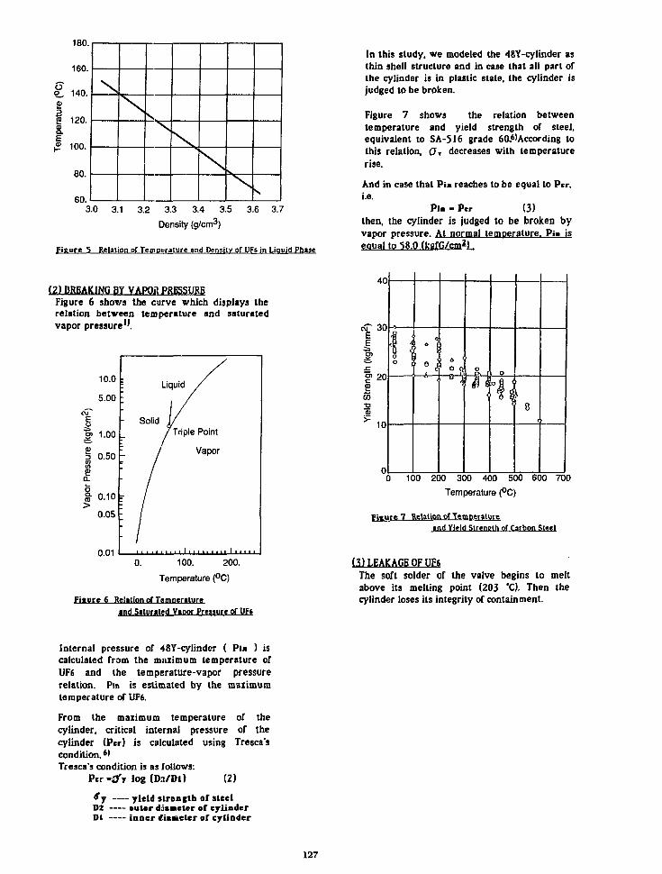
180.
160.
£ 140.8§ 120.
I,£ 100.
80.
60.
N
3.0 3.1 3.2 3.3 3.4 3.5 3.6 3.7Density (g/cm3)
Figure ^ Relation of Temperature and Density of UF6 in Liquid Phase
In this study, we modeled the 48Y-cylinder asthin shell structure and in case that all part ofthe cylinder is in plastic slate, the cylinder isjudged to be broken.
Figure 7 shows the relation betweentemperature and yield strength of steel,equivalent to SA-516 grade 60.6'According tothis relation. Or decreases with temperaturerise.
And in case that P u reaches to be equal to Per,i.e.
Pi- - Per (3)then, the cylinder is judged to be broken byvapor pressure. At normal temperature. Pi« iseoual to 58.0 (kefG/cm2).
(2) BREAKING BY VAPOR PRESSUREFigure 6 shows the curve which displays therelation between temperature and saturatedvapor pressure".
0.010. 100. 200.
Temperature (°C)
Fiture 6 Relation of Temperatureind Saturated Vapor Preasure of UFt
100 200 300 400 500 600 700
Temperature (°C)
fjf lire 7 Relation of Temperatureand Yield Strength of Carbon Steel
(3) LEAKAGE OF V?iThe soft solder of the valve begins to meltabove its melting point (203 *C). Then thecylinder loses its integrity of containment.
Internal pressure of 48Y-cyIinder ( Pi» ) iscalculated from the maximum temperature ofUF6 and the temperature-vapor pressurerelation. Pin is estimated by the maximumtemperature of UF6.
From the maximum temperature of thecylinder, critical internal pressure of thecylinder (Per) is calculated using Tresca'scondition.*'Tresca's condition is as follows:
Pcr-tfy log (D?./Dl) (2)
Sj yield strength of steelD2 outer diameter of cylinderDl inner tfiaueter of cylinder
127
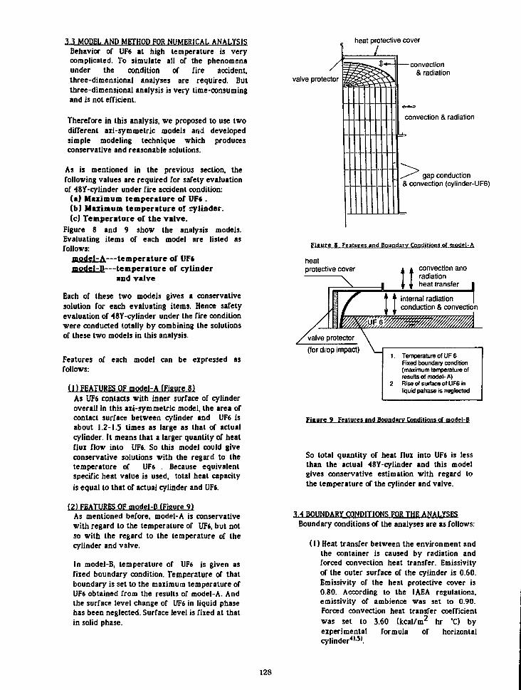
3.3 MODEL AND METHOD FOR NUMERICAL ANALYSISBehavior or UF6 at high temperature is verycomplicated. To simulate all of the phenomenaunder the condition or fire accident,three-dimensional analyses are required. Butthree-dimensional analysis is very time-consumingand is not efficient.
Therefore in this analysis, we proposed to use twodifferent axi-symmetric models and developedsimple modeling technique which producesconservative and reasonable solutions.
As is mentioned in the previous section, thefollowing values are required for safety evaluationof 48Y-cylinder under fire accident condition:
(a) Maximum temperature of UFf .(b) Maximum temperature of cylinder.(c) Temperature of the valve.
Figure 8 and 9 show the analysis models.Evaluating items of each model are listed asfollows:
model-A—temperature of UF*model-D—temperature of cylinder
and valve
Each of these two models gives a conservativesolution for each evaluating items. Hence safetyevaluation of 48Y-cylinder under the fire conditionwere conducted totally by combining the solutionsof these two models in this analysis.
Features of each model can be expressed asfollows:
1I) FEATURES OF model-A (Figure 8)As UF6 contacts with inner surface of cylinderoverall in this axi-sym metric model, the area ofcontact surface between cylinder and UF6 isabout 1.2-1.5 times as large as that of actualcylinder. It means that a larger quantity of heatflux flow into UF6. So this model could giveconservative solutions with the regard to thetemperature of UF6 . Because equivalentspecific heat value is used, total heat capacityis equal to that of actual cylinder and UFt.
(2) FEATURES OF model-B (Figure 9)As mentioned before, model-A is conservativewith regard to the temperature of UF6, but notso with the regard to the temperature of thecylinder and valve.
In model-B, temperature of UF6 is given asfixed boundary condition. Temperature of thatboundary is set to the maximum temperature ofUF6 obtained from the results of model-A. Andthe surface level change of UF6 in liquid phasehas been neglected. Surface level is fixed at thatin solid phase.
heat protective cover
-convection& radiation
convection & radiation
gap conduction& convection (cylinder-UF6)
Figure 8 Features and Boundary Conditions of model-A
heatprotective cover
Xconvection anaradiationheat transfer
internal radiationconduction & convection
(for drop impact)1. Temperature of UF 6
Fixed boundary condition(maximum temperature ofresults of model- A)
2. Rise of surface of UF6 inliquid pahase is neglected
Figure 9 Features »nd Boundary Condilioni of model-B
So total quantity of heat flux into UF6 is lessthan the actual 48Y-cylinder and this modelgives conservative estimation with regard tothe temperature of the cylinder and valve.
3.4 BOUNDARY CONDITIONS FOR THE ANALYSESBoundary conditions of the analyses are as follows:
(1) Heat transfer between the environment andthe container is caused by radiation andforced convection heat transfer. Emissivityof the outer surface of the cylinder is 0.60.Emissivity of the heat protective cover is0.80. According to the IAEA regulations,emissivily of ambience was set to 0.90.Forced convection heal transfer coefficientwas set to 3.60 (kcal/m2 hr *C) byexperimental formula of horizontalcylinder*'-51.
128

(2)Heat transfer between the cylinder and UF6is caused by conduction (in solid state) andnatural convection (in liquid state) heattransfer. Moreover efrect or thermal gap isconsidered at the first stage of the Tireaccident. This thermal gap grows because ofsublimation of UF6. In this analysis, theeffect of thermal gap is treated as gapconduction heat transfer. Value of gapconductance is according to the results oftests for material property of UF6 conductedby PNC3'.
(3)The effect of the valve protector for dropimpact was considered in CASE-2. As thestructure of the valve protector is notaii-symmetric physically, equivalent valueis used as the material property of thevalve protector in this analysis. In CASE-2,heat transfer between the protector (andheat protective cover) and the cylinder iscaused by radiation and conduction andnatural convection heal transfer of thecavity air.
H)Initial temperature is set to 38.0 "Caccording to IAEA regulations.
(5)Ambient temperature during fire accident isset for 800 "C. And after fire accident hasterminated, it is 38.0 *C.
(6)Emissivity of free surface of UF6 is set for1.0.
3.5 MATERIAL PROPERTYTable 2-4 show material properties. Properties ofnatural UF6 is based on some papers"'2' andexperimental data of PNC3'. Effect of convection ofUFS in liquid phase is treated as equivalentconduction heat transfer. Nusselt number is about80.0, which was calculated according to theexperimental formula of cavily fluid convectionbetween surfaces of two concentric cylinders^'-".
T»ble 4 Mileriil Properties of UFt
(I > Density ind Specific Hea! (s-in solid state, 1-in liquid state)
Density (kg/m3)
Specific Heal (kcal/kg T)
Temperature CO
10. 50. 64(s) 64.(1) 150.
5136. 4933. 4802. 3630. 3031.
0.110 0.120 0.124 0.133 0.136
(2) Thermal Conductivity (s-in solid state, l-in liquid stale)
Conductivity (kcal/m hr X)
Temperature CO
20. 55. 64.(s) 64.(1)
0.353 2.579 3439 3150
(3) Latent Heat
1303 kcal/kg at 64.052 X
3.6 VERIFICATION OF THE VALIDITY OF THE MODELFor the purpose of verification of the validity ofthe analysis model mentioned in 3.3. some simplecases were conducted.
Figure 10 shows the object for the verificationanalysis. It is a steel cylinder whose length is 4.03m, diameter (inside) 1.20 m and thickness of theshell 15.0 mm. Material inside the cylinder hassimilar thermal properties lo those of natural UF6,which is shown in Table 5- It occupies 60 % of theinside volume of the cylinder. As the thermalconductivity is set at infinity, temperaturedistribution of the material stays uniform.
Cylinder
1200 mm
Table 2 Material Properties of Carbon Steel
Density (kg/m3) 7850
Specific Heat (kcal/kg *C) 0.11
Conductivity (Iccal/m hr "0 53.0
Table 3. Material Properties of Heat Protective Cover
Density (kg/m3)
Temperature CO
162. 311. 475. 649.
566!
Specific Heal (kcal/kg *C) 0.12 0.22 0.23 0.24
Conductivity (kcal/m hr 'O 0.10 0.14 0.17 0.21
Figure 10 Cylinder Model for Verifivation Analysis
Table *> Material Properties: Density is the value in solid phaseIn liquid phase, it changes according lo Ihe temperature as isdisplayed in Figure 5.
Density (kg/m3)
Specific Heal (kcal/kg X)
Latent Heat (kcal/kg)
4800.
0.120
12.0 at 60.0 "C
129

In this verification analysis, three kinds of modelswere used. Two of them are axi-symmetric modelswhich are equivalent to model-A and model-Bmentioned in 3.3. The third one is athree-dimensional model shown in Figure 11.
Boundary conditions are similar to thosementioned in 3.4, under the fire accident conditionof 600 'C for the duration of 30 minutes. In thisverification analysis, both ends of the cylinder areinsulated for the length of 715.0 mm from the edgeshown in Figure 12 and effect of thermal gapbetween the material and the cylinder is not takeninto account. For the three-dimensional modelezpansion of the material in liquid phase isconsidered.
Figure 11 Three-Dimensional Model for Verification Analysis
I715 mm1 n
CONVECTION &RADIATION
'//////////A
Figure 12 Boundary Conditions of Verification Analysis
Figure 13 and Figure 14 show the results of thisverification analysis. The results of axi-symmetricmodels (model-A and modei-fi) andthree-dimensional model show good agreement.And axi-sym metric models give conservativesolutions.
Table 6 shows required CPU time measured onVAX 11/780 for the analyses. The method withaxi-sym metric model displays excellent efficiency.The efficiency is about 45 times from the point ofview of CPU time.
0.5-
g> 0 . 4 -
ra
g. 0.3-
"g 0.2-
0.0
model-A (solid line)
3-dim. model (dashed line)
0. 10. 20. 30.Time (min.)
Figure 13 Results of Verification Analysis
(Temperature of the Material)
1.0-1model-B (solid line)
0.00.
Time (min.)Figure 14 Results of Verification Analysis (Mai. Temperature of
Cylinder)
Table 6. CPU time of each model measured on VAX 11 /780
model-A 380 sec
model-B 100 sec
Three-Dimensional Model 17500 sec
3.7 RESULTS OF NUMERICAL ANALYSESTable 7 and Figure 15-18 show the results of thenumerical analyses of 48Y-cyIinder filled withnatural UF6.
Maximum volume of UF6 is 96X (CASB-1) and 86x(CASE-2) of cylinder capacity, so the hydraulicbreaking does not take place even if without theheal protective covers.
Maximum vapor pressure is lower than criticalinternal pressure of cylinder in each case, so thebreaking of cylinder by vapor pressure does notoccur.
Maximum temperature of the valve is 144 "C inCASE-2 and the soft solder does not melt.Therefore the integrity of containment can be kept.
130
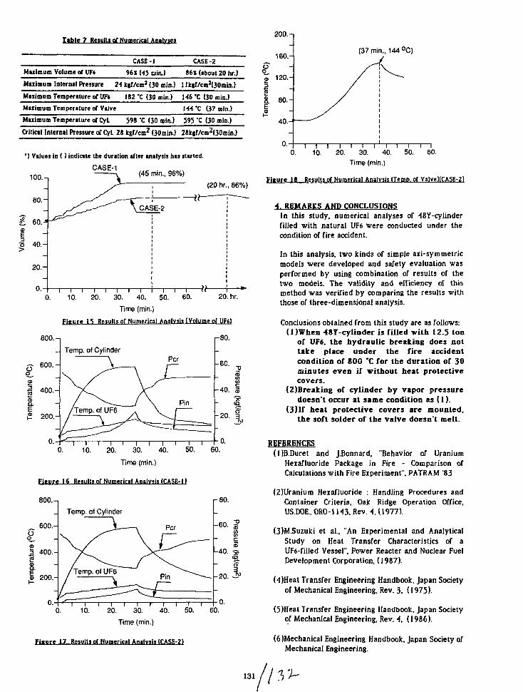
Table 7 Results of Numerical Analyses
CASE-I CASE-2
Maximum Volume of UF* 96X U5 din.) 86* (ibouf 20 hr.)
Maiimum Internal Pressure 2A kgf/cm2 (30 min.) 1 Jkgr/cm2(30min.)
Miiimum Temperature of 0F« 182 X (30 min.) 1-46 'C (30 min.)
Miiimum Temperiture of Valve M4'C (37 min.)Maiimum Temperature of Cyl 598 'C (30 min.) 595 'C (30 min.)
Critical Internal Pressure of Cyl. 28 kgf/cm2 (30min.) 2SkgT/cm2(30min.)
') Values in ( ) indicate the duration after analysis has started.
CASE-1100.-, (45 min., 96%)
(20 hr., 86%)
0. 10. 20. 30. 40. 50. 60. 20. hr.
Time (min.)Fi.ure IS Results of Numerical Analysis (Volume of UFt)
800.-, r80.
Temp, of CylinderPer ^60.
10. 20. 30. 40. 50. 60.
3
-40. I
-20.
0.
Time (min.)
Fiture 16 Results of Numerical Analysis (CASE-11
800.-,
_ 600.-O
£= 400.-
200.-
0.-
Temp, of Cylinder
Per
-80.
§ih40. ^
03
-20.
i i i i i i i i i i i0. 10. 20. 30. 40. 50. 60.
Time (min.)
Fi«ure 17 Results of Numerical Analysis (CASE-2)
0.
O
200.-n
160.-
120.-
S. 80.-
I40.-
0.
(37 min., 144 °C)
r I I I f r i v i i i I0. 10. 20. 30. 40. 50. 60.
Time (min.)
Fiture 18 Results of Numerical Analysis (Temp, of ValvcHCASE-2)
4. REMARKS AND CONCLUSIOHSIn this study, numerical analyses or 48Y-cylinderfilled with natural UF6 were conducted under thecondition of fire accident.
In this analysis, two kinds of simple aii-symmetricmodels were developed and safety evaluation wasperformed by using combination of results of thetwo models. The validity and efficiency of thismethod was verified by comparing the results withthose of three-dimensional analysis.
Conclusions obtained from this study are as follows:(l)When 487-cylinder is Tilled with 12.5 ton
of UF6. the hydraulic breaking does nottake place under the fire accidentcondition or 800 *C for the duration of 30minutes even if without heat protectivecovers.
(2)Breaking or cylinder by vapor pressuredoesn't occur at same condition as (1).
(3)If heat protective covers are mounted,the soft solder of the valve doesn't melt.
REFERENCES(l)B.Duret and J.Bonnard, "Behavior of Uranium
Heiafluoride Package in Fire - Comparison ofCalculations with Fire Experiment'. PATRAM '83
(2)Uranium Heiafluoride : Handling Procedures andContainer Criteria, Oak Ridge Operation Office,US.DOE, ORO-1143, Rev. 4. (1977).
(3)M.Suzuki et al., "An Experimental and AnalyticalStudy on Heat Transfer Characteristics of aUF6-filled Vessel". Power Reader and Nuclear FuelDevelopment Corporation, (1987).
HjHeat Transfer Engineering Handbook. Japan Societyof Mechanical Engineering, Rev. 3. (! 975).
(5)Heat Transfer Engineering Handbook, Japan Societyof Mechanical Engineering, Rev. 4. (1986).
(6 Mechanical Engineering Handbook. Japan Society ofMechanical Engineering.

THERMAL BEHAVIOUR OF THE TYPE 30B CYLINDER EQUIPPEDWITH THE 21PF.1 OVERPACK AND STUDY OF PROTECTIVE COVERS
FOR THE 48Y CYLINDER VALVE
P. Wamiez and C. RingotCEA/IPSN, Fontenay, France
J. PerrotCEA/CESTA, Bordeaux, France
H. BernardCOGEMA, V61izy, France
ABSTRACT INTRODUCTION
This paper describes the tests which have been performed inFrance:
• first to verify the behaviour of 30B cylinders with their 21PF. 1protective overpack,
• secondly to develop a better mechanical protection of the valve.
1 - The thermal tests have been performed on real packagings filledwith UF6, after the mechanical AIEA tests (free drop 9 m and1 m on a pitch).
A methodical approach has been used with large thermalinstrumentation:
• tests with inert material,
• transposition by calculation of the results to the case of UF6
filling,
• confirmation tests with UF,.o
The results were very satisfactory, the maximal temperatureswhich were measured on the external overpack of the 30B cylinderbeing much lower than the filling temperature.
2 - In the Mont Louis wreckage, some of the valves of 48 Y cylinderswere damaged, as a consequence of the displacement of theprotecting cover, and two of them were so damaged as to enablewater to enter the cylinder.
A new valve protector was designed and was tested under impactsituations.
The test programme was performed with the two designs: thestandard one and the new protecting covers.
The tests have demonstrated that the new design which has thesame weight as the original one and which may be used without anymodifications of the cylinder, has a better behaviour, increasing thesafety during transport.
In the last few years, tests have been carried in France to check notonly the mechanical and thermal behaviour of the 30B cylindersequipped with the 21PF.1 overpack, but also to improve theprotection of the valve of the 48Y cylinder against the differentloadings to which it can be subjected.
1. THERMAL BEHAVIOUR OF THE 30B CYLINDEREQUIPPED WITH THE 21PF.1 OVERPACK
1.1 General
The purpose of this study was to check the behaviour of theassembly consisting of the 30B cylinder, the 21 PF. 1 overpack andthe sample bottle, particularly concerning the resistance of thecylinder to breaking when the package is submitted to drop and fireaccident conditions with an actual UF6 content, test conditionswhich had never been previously achieved.
The tests were carried out by the Commissariat a I'EnergieAtomique (CEA) on the test facility of the Centre d'EtudesScientifiqueset Techniques d'Aquitaine (CESTA) near Bordeaux.
1.2 Nature of tests
The same cylinder-overpack-sample bottle assembly was sub-jected to three successive trials, with cumulative effect, in thefollowing order [1]:
• free 9 metre drop onto a concrete slab covered with a steelplate, the impact occurred at the generatrix corresponding to thejoint of the two half overpacks, in order to obtain damage cor-responding to the maximum risk with regard to breaking in thesubsequent fire test;
• free 1 metre drop onto a metal bar rigidly welded to the steelplate of the target, the impact occurred in the vicinity of thecentral reinforcement and the wooden frame of the overpack, themost fragile part of the zone already exposed the 9 metre drop,without opening the package;
133

• fire: after expert examination and instrumentation, the assem-bly already subjected to the preceding tests was placed 1 metreabove the surface of a fuel source of kerosene on a speciallydesigned stand; the joint of the two half overpacks was placedvertically so that the zone exposed to attack in the two precedingtests was exposed to the flames, the duration of the fire being30 minutes.
Different phases of the tests were filmed from different angles forsubsequent examination and checking.
For the fire test, the assembly was equipped with thermocouplesconnected to a temperature data acquisition system enablingmonitoring and recording of data during test and subsequentcooling phase.
1 3 Test programme and results [2]
The final purpose of the test programme was to carry out tests ona cylinder filled with UF6 but, for safety reasons, as it was preferrednot to take the risk of releasing a large amount of UF6 into theenvironment, nor to have a reaction between the UF6 and thekerosene during the fire test, a methodical approach by steps wasprovided for:
• tests with inert ballast simulating UF6,
• transposition by calculation to a test with UF6 of the resultsobtained with inert matter, then examination of all experimentalaspects from the safety viewpoint,
• tests with UF6 taking the appropriate precautions.
1.3.1 Tests with inert ballast
The ballast used to simulate UF6 consisted of a mixture of steel ballsof 3 mm diameter and paraffin wax. This mixture was chosenbecause its physical properties are close to those of UF6: density,specific heat and thermal conductivity. Furthermore, the paraffinwax, which was introduced in liquid form at 60°C, is solid atambient temperature and naturally sticks to the wall after cooling,making it possible to obtain a representative centre of gravity forthe assembly, before the impact test.
After the 9 metre drop, the joint of the overpack was slightlydistorted, the wooden frames of the two half overpacks beingdamaged. Two attachment bolts broke.
The puncture test with the bar resulted in substantial deformationand tearing of the overpack at the point of the impact.
On opening the overpack for examination and instrumentation forthe fire test, it was found that the cylinder had turned through ap-proximately 90° within the overpack, the only damage sustainedwas a dent 350 mm long, 200 mm wide and 25 mm deep caused bythe bar.
For the fire test, the damaged package was instrumented with28 thermocouples. Exposure to fire was extended to 90 minutes tostudy the safety margins.
During the first 30 minute period, the hottest point on the outsideof the 30B cylinder was 75°C, with an average of 58°C for all thepoints of measurement; the sample bottle was at 25°C. After
90 minutes, these temperatures were respectively 170°C, IO1°Cand70°C.
After complete cooling, the cylinder was immersed in water at adepth of 0.9 metre for 8 hours without water entering.
After these tests, the cylinder was submitted at 80°C to a hydraulicpressure of 28 bars without significant residual deformation.
1.3.2 Transposition of thermal results to fire test with UF6
Using the preceding results, a calculation was made which showedthat the temperatures reached by the cylinder in the test with UF6
would remain, after 30 minutes, well below the temperature main-tained at the time of filling (100°C) and that in the worst case, theamount of UF6 melted would be very small.
The risk of hydraulic bursting could therefore be excluded, butleakage by the valve or plug remained a possibility.
1.3.3 Tests with UF6
A new cylinder-overpack-sample bottle assembly was used. The30B cylinder was filled with 2,150 kg of depleted UF6 (U235content 0.2%). The sample bottle, which was placed in its woodenbox, contained 439 g of UF6.
1.3.3.1 Drop and puncture tests
The drop and puncture tests were carried out, as in the tests withinert ballast in the existing facilities, with the following results:
• after the 9 metre drop test
- the joint between the two half overpacks was damaged and a4 cm gap formed at the point of the impact;
- no bolts were broken but 3 nuts at the joint, on the sideopposite the impact, were loosened;
- the outer metal skin of the upper half overpack had a tear 5 cmlong close to the central angle section.
• after the puncture test
- the outer metal skin of the overpack was substantiallydistorted and tom at the point of the impact.
• after opening the overpack
- no damage to the sample bottle or its packing was found;
- the 30B cylinder had turned through about 50° within theoverpack;
- there was a dent in the cylinder, caused by the bar, 485 mmlong, 230 mm wide and 9 mm deep.
1.3.3.2 Fire test
For the fire test, a special area was fitted out. The damaged zoneof the overpack was located at the bottom, exposed to the flames.The cylinder was placed so that the valve was at the top.
To detect any leakage of UFe from the valve and plug and to directany outflow away from the kerosene pan, the cylinder was speciallyequipped. Leaktight lines were connected to the valve and drainplug; air circulation was provided in these lines which wereconnected to detectors.
134
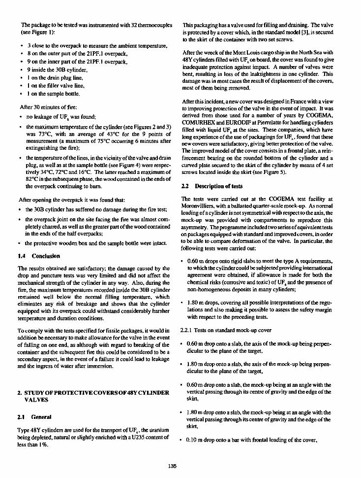
The package to be tested was instrumented with 32 thermocouples(see Figure 1):
• 3 close to the overpack to measure the ambient temperature,• 8 on the outer part of the 21PF. 1 overpack,• 9 on the inner part of the 21 PF. 1 overpack,• 9 inside the 30B cylinder,• 1 on the drain plug line,• 1 on the filler valve line,• 1 on the sample bottle.
After 30 minutes of fire:
• no leakage of UF6 was found;
• the maximum temperature of the cylinder (see Figures 2 and 3)was 73°C, with an average of 43°C for the 9 points ofmeasurement (a maximum of 75°C occurring 6 minutes afterextinguishing the fire);
• the temperature of the lines, in the vicinity of the valve and drainplug, as well as at the sample bottle (see Figure 4) were respec-tively 34°C, 72°C and 16°C. The latter reached a maximum of82°C in the subsequent phase, the wood contained in the ends ofthe overpack continuing to burn.
After opening the overpack it was found that:
• the 30B cylinder has suffered no damage during the fire test;
• the overpack joint on the site facing the fire was almost com-pletely charred, as well as the greater part of the wood containedin the ends of the half overpacks;
• the protective wooden box and the sample bottle were intact.
1.4 Conclusion
The results obtained are satisfactory; the damage caused by thedrop and puncture tests was very limited and did not affect themechanical strength of the cylinder in any way. Also, during thefire, the maximum temperatures recorded inside the 30B cylinderremained well below the normal filling temperature, whicheliminates any risk of breakage and shows that the cylinderequipped with its overpack could withstand considerably harshertemperature and duration conditions.
To comply with the tests specified for fissile packages, it would inaddition be necessary to make allowance for the valve in the eventof falling on one end, as although with regard to breaking of thecontainer and the subsequent fire this could be considered to be asecondary aspect, in the event of a failure it could lead to leakageand the ingress of water after immersion.
2. STUDY OF PROTECTIVE COVERS OF48Y CYLINDERVALVES
2.1 General
Type 48Y cylinders are used for the transport of UF6, the uraniumbeing depleted, natural or slightly enriched with a 17235 content ofless than 1%.
This packaging has a valve used for filling and draining. The valveis protected by a cover which, in the standard model [3], is securedto the skirt of the container with two set screws.
After the wreck of the Mont Louis cargo ship in the North Sea with48 Y cylinders filled with UF6 on board, the cover was found to giveinadequate protection against impact. A number of valves werebent, resulting in loss of the leaktightness in one cylinder. Thisdamage was in most cases the result of displacement of the covers,most of them being removed.
After this incident, a new cover was designed in France with a viewto improving protection of the valve in the event of impact. It wasderived from those used for a number of years by COGEMA,COMURHEX and EURODIF at Pierrelatte for handling cylindersfilled with liquid UF6 at the sites. These companies, which havelong experience of the use of packagings for UF6, found that thesenew covers were satisfactory, giving better protection of the valve.The improved model of the cover consists in a frontal plate, a rein-forcement bearing on the rounded bottom of the cylinder and acurved plate secured to the skirt of the cylinder by means of 4 setscrews located inside the skirt (see Figure S).
2.2 Description of tests
The tests were carried out at the COGEMA test facility atMoronvilliers, with a ballasted quarter-scale mock-up. As normalloading of a cylinder is not symmetrical with respect to the axis, themock-up was provided with compartments to reproduce thisasymmetry. The programme included two series of equivalent testson packages equipped with standard and improved covers, in orderto be able to compare deformation of the valve. In particular, thefollowing tests were carried out:
• 0.60 m drops onto rigid slabs to meet the type A requirements,to which the cylinder could be subjected providing internationalagreement were obtained, if allowance is made for both thechemical risks (corrosive and toxic) of UF6 and the presence ofnon-homogeneous deposits in many cylinders;
• 1.80 m drops, covering all possible interpretations of the regu-lations and also making it possible to assess the safety marginwith respect to the preceding tests.
2.2.1 Tests on standard mock-up cover
• 0.60 m drop onto a slab, the axis of the mock-up being perpen-dicular to the plane of the target,
• 1.80 m drop onto a slab, the axis of the mock-up being perpen-dicular to the plane of the target,
• 0.60 m drop onto a slab, the mock-up being at an angle with thevertical passing through its centre of gravity and the edge of theskirt,
• 1.80 m drop onto a slab, the mock-up being at an angle with thevertical passing through its centre of gravity and the edge of theskirt,
• 0.10 m drop onto a bar with frontal loading of the cover.
135

• 0.30 m drop onto a bar with frontal loading of the cover,
• 0.10 m drop onto a bar with lateral loading of the cover.
2.2.2 Tests on improved cover
• 0.60 m drop onto a slab with the axis of the mock-upperpendicular to the plane of the target,
• 0.60 m drop onto a slab with the mock-up at an angle, the verticalpassing through its centre of gravity and the edge of the skirt,
• 1.80m drop onto a slab with themock-upatan angle, the verticalpassing through its centre of gravity and the edge of the skirt,
• 0.10 m drop onto a bar with frontal loading of the cover,
• 0.30 m drop onto a bar with frontal loading of the cover,
• 0.10m drop onto a bar with lateral loading of the cover.
For frontal loading of the cover, the cylinder was slightly inclinedwith respect to the horizontal plane to allow the passage of the bar.The point of impact was located on the lower part of the cover (seeFigure 6).
For lateral loading of the cover, the cylinder was at 90° with respectto the preceding test position. The cylinder was also slightlyinclined to allow passage of the bar (see Figure 7).
23 Test results
For the different types of drop, the tests gave the following results:
• drop onto slab
For the two types of covers, the drops did not damage the valve.
• drop onto slab at an angle
Height of drop 0.60 m: with the standard cover, the valve wasbent; with the improved cover, it remained intact.
Height of drop 1.80 m: with the standard cover, the valve wassheared off; with the improved cover, it remained intact.
• drop onto bar
Height of drop 0.10 m: the improved cover protected the valvein all cases, the valve remaining intact. However, with the stan-dard cover, it was sheared off in the case of lateral loading.
Height of drop 0.30 m: in the case of frontal loading, the valvewas damaged with both types of cover. It was bent with thestandard cover and sheared off with the new model cover.
2.4 Conclusion
The tests confirmed what had already been concluded when assess-ing the safety of handling 43Y cylinders in the plants and whenloading at incidents (the wreck of the Mont Louis cargo ship in par-ticular), i.e. that the standard cover inadequately protects the valveagainst impact, particularly against lateral loads which can occurduring handling.
In the event of a drop at an angle and impact on the valve, protectionof the valve is considerably improved with the cover designedstudied by COGEMA. Furthermore, as its weight remains withinreasonable limits, being only slightly higher than that of the stan-dard cover, it can be handled without special tackle and its usewould necessitate no special modification of the 3DB cylinders.
REFERENCES
[1] IAEA Safety Series No. 6
[2] Report on behaviour studies performed by CESTA (alreadyforwarded to the competent American authorities)
[3] ANSI Standard 14.1 (1982)
136
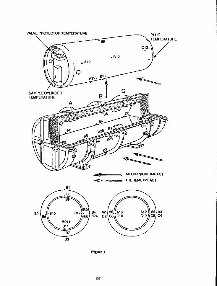
VALVE PROTECTOR TEMPERATURE PLUGTEMPERATURE
SAMPLE CYLINDERTEMPERATURE
MECHANICAL IMPACT
THERMAL IMPACT
B4 A2B24 C2
Figure 1
137
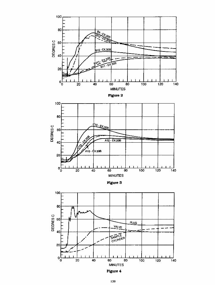
100
80
3 60
HIECO
S 40
20
—
-; ima
~ |
h1 1
/f
• 11 1 1
R10-EX-30B
1 1 1
—
1 1 1
• —
1 1 1
— — — _
1 1 1
—
1 1 120 40 60 80 100 120 140
MINUTES
Figure 2
100
oCOLU£TOtilQ
20 40 60 80 100 120 140MINUTES
Figure 3
100
80
O60
oHI
40
20
—
-. / '
i i i
—
1 1 1
_VALV£_
1 1 1
PLUG
1 1 1 1 1 1
.
I 1 1
20 40 60 80MINUTES
Figure 4
138
100 120 140

120 '4NUTS Q50x50M16
ii_ 1 .
/// , 4 PRESSURE SCREWS/ / WITH ROUNDED END
01232
\?45°\ III 45°V
• ' CYLINDER SKIRT
Figure 5
H-| = 0,10 m
H2 = 0,30 m
Hi = 0,10 m
H2 = 0,30 m
139
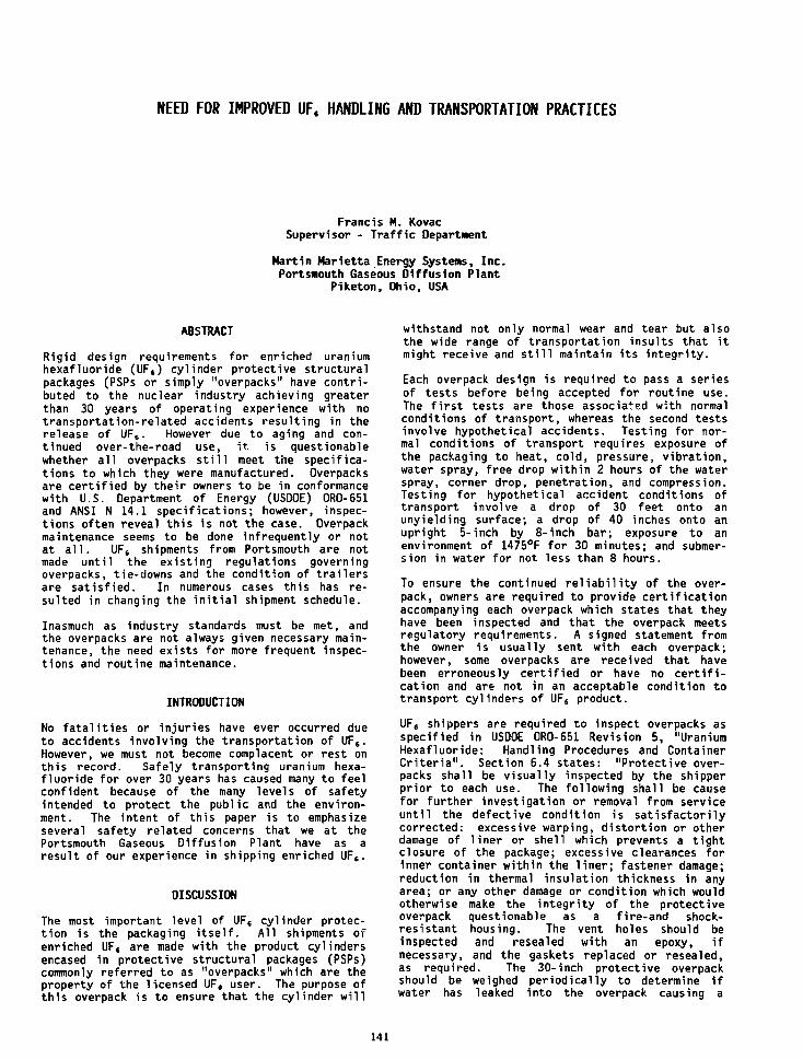
NEED FOR IMPROVED UFt HANDLING AND TRANSPORTATION PRACTICES
Francis M. KovacSupervisor - Traffic Department
Martin Marietta Energy Systems, Inc.Portsmouth Gaseous Diffusion Plant
Piketon, Ohio, USA
ABSTRACT
Rigid design requirements for enriched uraniumhexafluoride (UFt) cylinder protective structuralpackages (PSPs or simply "overpacks" have contri-buted to the nuclear industry achieving greaterthan 30 years of operating experience with notransportation-related accidents resulting in therelease of UF6. However due to aging and con-tinued over-the-road use, it is questionablewhether all overpacks still meet the specifica-tions to which they were manufactured. Overpacksare certified by their owners to be in conformancewith U.S. Department of Energy (USDOE) ORO-651and ANSI N 14.1 specifications; however, inspec-tions often reveal this is not the case. Overpackmaintenance seems to be done infrequently or notat all. UF, shipments from Portsmouth are notmade until the existing regulations governingoverpacks, tie-downs and the condition of trailersare satisfied. In numerous cases this has re-sulted in changing the initial shipment schedule.
Inasmuch as industry standards must be met, andthe overpacks are not always given necessary main-tenance, the need exists for more frequent inspec-tions and routine maintenance.
INTRODUCTION
No fatalities or injuries have ever occurred dueto accidents involving the transportation of UF6.However, we must not become complacent or rest onthis record. Safely transporting uranium hexa-fluoride for over 30 years has caused many to feelconfident because of the many levels of safetyintended to protect the public and the environ-ment. The intent of this paper is to emphasizeseveral safety related concerns that we at thePortsmouth Gaseous Diffusion Plant have as aresult of our experience in shipping enriched UF».
DISCUSSION
The most important level of UF6 cylinder protec-tion is the packaging itself. All shipments ofenriched UF, are made with the product cylindersencased in protective structural packages (PSPs)commonly referred to as "overpacks" which are theproperty of the licensed UF, user. The purpose ofthis overpack is to ensure that the cylinder will
withstand not only normal wear and tear but alsothe wide range of transportation insults that itmight receive and still maintain its integrity.
Each overpack design is required to pass a seriesof tests before being accepted for routine use.The first tests are those associated with normalconditions of transport, whereas the second testsinvolve hypothetical accidents. Testing for nor-mal conditions of transport requires exposure ofthe packaging to heat, cold, pressure, vibration,water spray, free drop within 2 hours of the waterspray, corner drop, penetration, and compression.Testing for hypothetical accident conditions oftransport involve a drop of 30 feet onto anunyielding surface; a drop of 40 inches onto anupright 5-inch by 8-inch bar; exposure to anenvironment of 1475°F for 30 minutes; and submer-sion in water for not less than 8 hours.
To ensure the continued reliability of the over-pack, owners are required to provide certificationaccompanying each overpack which states that theyhave been inspected and that the overpack. meetsregulatory requirements. A signed statement fromthe owner is usually sent with each overpack;however, some overpacks are received that havebeen erroneously certified or have no certifi-cation and are not in an acceptable condition totransport cylinders of UF6 product.
UF6 shippers are required to inspect overpacks asspecified in USDOE ORO-651 Revision 5, "UraniumHexafluoride: Handling Procedures and ContainerCriteria". Section 6.4 states: "Protective over-packs shall be visually inspected by the shipperprior to each use. The following shall be causefor further investigation or removal from serviceuntil the defective condition is satisfactorilycorrected: excessive warping, distortion or otherdamage of liner or shell which prevents a tightclosure of the package; excessive clearances forinner container within the liner; fastener damage;reduction in thermal insulation thickness in anyarea; or any other damage or condition which wouldotherwise make the integrity of the protectiveoverpack questionable as a fire-and shock-resistant housing. The vent holes should beinspected and resealed with an epoxy, ifnecessary, and the gaskets replaced or resealed,as required. The 30-inch protective overpackshould be weighed periodically to determine ifwater has leaked into the overpack causing a
141

weight gain. Overpack tie-downs should beinspected to assure that they are not damaged andare adequate for their intended use."
The "American National Standard for Packaging ofUranium Hexafluoride for Transport," ANSIN14.1-1987, Section 7.4.1 also specifies a routineoperational inspection. Besides including theforegoing from USDOE 0R0-651, it states:
"The outer protective packaging shall also beinspected for evidence of the inleakage of waterinto the packaging. Any evidence of inleakage ofwater shall require an investigation of thepackaging to determine the amount of water presentin the packaging. The packaging may be requiredto have the weight recertified if found necessaryby the investigation. The water shall be removedprior to repair of the outer protective packaging.Any nonconforming conditions found by the inspec-tor shall be referred to personnel designated bythe shipper to evaluate for the use, repair, orcondemnation of protective packaging. The repre-sentative of the shipper shall contact the ownerand user of the protective packaging for recommen-dations concerning any repair of modification ofthe packaging."
Inspection at Portsmouth indicates that many30-inch cylinder overpacks no longer meet designcriteria due to extended usage and normal wear andtear. Some owners have become lax in performingperiodic preventative maintenance to the extentthat an inordinate number of overpacks do not nowmeet design specifications. While it is theowner's responsibility to assure maintenance andrepair of their own overpacks, the PortsmouthGaseous Diffusion Plant occasionally performs somemaintenance, which is billed to the owner, byrepairing or replacing bad gaskets or strippednuts and bolts, repairing minor welds, andrepairing seal rings. We must reject overpackswhen the repairs are extensive or exceed ourrepair capabilities. In that case, loading, andshipping schedules have been changed and the ownernotified to send a replacement overpack. Examplesof overpacks out of specification are shown inFigures 1, 2, and 3.
In addition to our concern with the questionablecertification of overpacks discussed above, thereceipt of cylinders and overpacks for inter-national shipments has presented two other areasof concern -- tie-down methods and the conditionof trailers. The first involves the various tie-down methods encountered for securing the over-packs to the shipping trailer beds. The designmethod for securing the overpack during shipmentis to bolt its base to the trailer bed. Sincemost domestic shipping trailers are dedicated toUF6 cylinder transportation, the overpacks remainbolted to the trailer beds and these overpacks aretransported in the designed manner. However,numerous trailers for international shipment havebeen received with improperly and potentiallydangerously secured overpacks. Examples of non-standard tie-down methods employed on incomingshipments are shown in Figures 4 through 7. Inorder that these shipments meet design specifica-tions, holes will have to be drilled in thetrailer bed and the overpacks properly secured forthe return shipment.
The American National Standard Institute, is inthe process of drafting Standard N14.2, "Tie-down
for Truck Transport of Radioactive Materials" anda subcommittee has been appointed to specificallyaddress the methods of securing UF, 30-inch over-packs to trailers.
Tie-downs are recognized as an internationalproblem and a conference addressed this topic onApril 29, 1988 in Vienna. In addition, theInternational Atomic Energy Agency (IAEA) hasissued for comment document ISO/DIS 7195"Packaging of Uranium Hexafluoride for Transport."Section 6.2.3 is entitled "Tie-down Arrangements."The comment period is not yet closed, and it isunknown how soon or in what specifics the regula-tions will become effective. The IAEA has alsoissued for comment TECDOC-423, "Recommendationsfor Providing Protection During the Transport ofUranium Hexafluoride" which recognizes thisproblem area, but final review and implementationare yet to be determined.
The second major concern to have arisen withinternational shipments is the condition of thetrailers themselves. Many trailers have not beenloaded at Portsmouth due to mechanical problems,rotten flooring, bald tires, no brakes or brakelights, or broken springs. Examples of defectswhich have resulted in trailers being rejected foruse are shown in Figures 8 and 9. A recent DOEdirective states that questionable shipping prac-tices are to be documented for DOE who will advisethe DOT and appropriate state agencies.
CONCLUSION
Owners of cylinder overpacks must keep currenttheir required periodic inspections and main-tenance to assure that shipment schedules are notchanged due to rejection of the overpacks and moreimportantly, to ensure that the safety of thecylinder is maintained during transport. TheDepartment of Transportation Research and SpecialPrograms Administration (RSPA) has issued for com-ment docket HM-166V, "Hazardous Materials, UraniumHexafluoride" which addresses periodic overpackmaintenance and which will codify ANSI N14.1 1987.
Currently there are no regulations for the methodof securing overpacks, however, this need is beingaddressed by ANSI and other organizations. Ourexperience strongly suggests that when regulationsarid standards are received, they must be imple-mented expeditiously to guarantee maintaining oursafety record. Even though these regulations willbe a most positive development when finallyissued, I further propose that a program be estab-lished to design special trailers and dedicatethem to the transport of UF6 nationally as well asinternationally. Engineered tie-downs can bedeveloped on a low center of gravity trailer whosemaintenance can be monitored and whose ownerswould be held accountable for trailers meeting DOTstandards.
Our industry has compiled an enviable transporta-tion safety record due to the basic designintegrity of the packaging. By developing dedi-cated trailers we will further demonstrate ourcontinued commitment to safety and control of allfacets of the transportation cycle. Together wemust continue to fulfill our transportation andlogistics responsibilities, and maintain ourenviable safety record in the handling andtransportation of UFS.
142

Fig. 1. Overpack Interior Showing Water Inleakage, Loose Strip Joint(Arrow at Knife Under Stop Strip), and Warped Steel Liner (arrow)
Fig. 2. Overpack Interior Showing Disintegrationdue to Water Saturation of the wooden Frame Member
Fig. 3. Leakage of Water Through theOverpack Exterior Wall
143
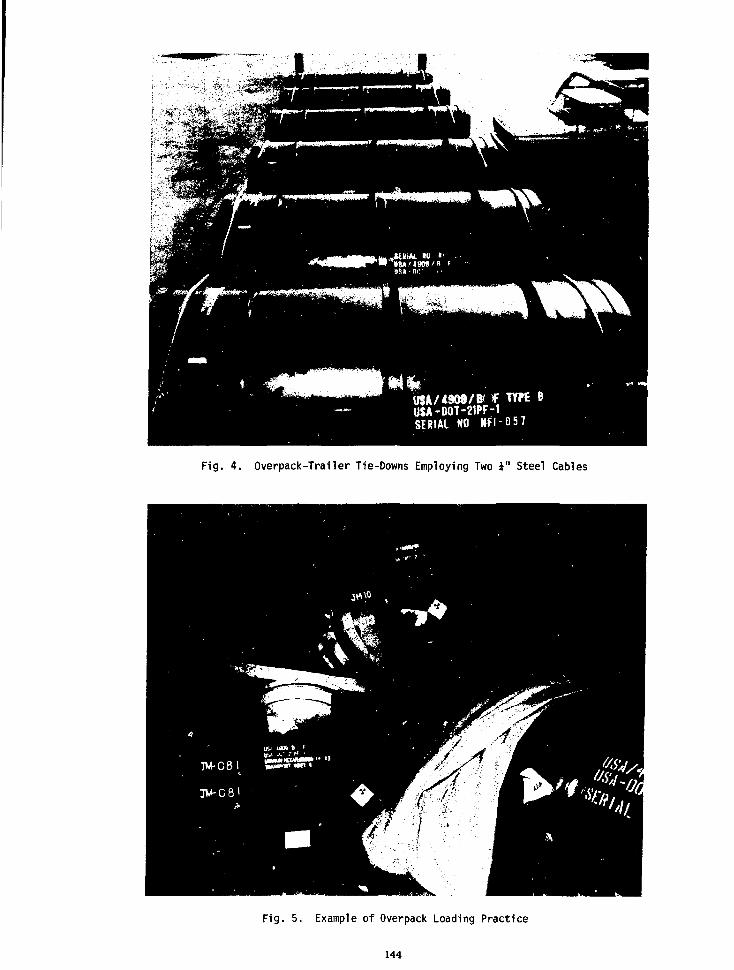
*,a^i*#t
USA/49M/BUSA-D0T-21PF-1SERIAL HO HFI -Q57
Fig. 4. Overpack-Trailer Tie-Downs Employing Two i " Steel Cables
Fig. 5. Example of Overpack Loading Practice
144

Fig. 6. Overpack-Trailer Tie-Down Employing Two Steel Straps per Two Overpacks
Fig. 7. "Boy Scout" Overpack Tie-Down Method
145
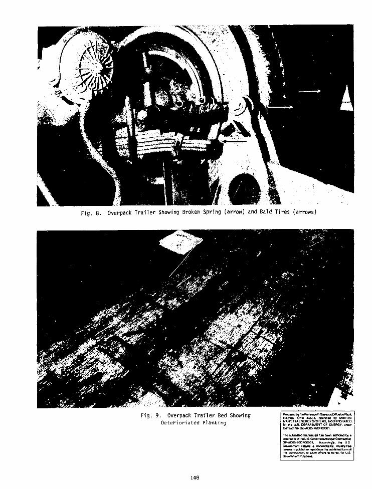
Fig. 8. Overpack Trailer Showing Broken Spring (arrow) and Bald Tires (arrows)
Fig. 9. Overpack Trailer Bed ShowingDeterioriated Planking
PrapamdbythsPorttmouihGacwutDmuiionPlvri.Plkrton. Ohio 45661. operated by MARTINMARIETTAENERGY SYSTEMS. INCORPORATED.for th« U.S. DEPARTMENT OF ENERGY. und*rContrMNaDE-AC05-7GOfl00001.
The submMsd mamftcrfct hm ba«n authoract by *coniraciorot Ih« U.S. Gov«mm»M undtrContrad No.DE-AC05-76ORO0001. AccordtnoV. trw U.S.Gov»rrtm»ni ratans a nonaidutW. royahyrra*lk»nu to publish or reproduce tb* publkhad torm ofthis contrbuiion, or a l b * oirwt 10 00 no. tor U.S.Gcv»rnm»ni Purpose*.
146
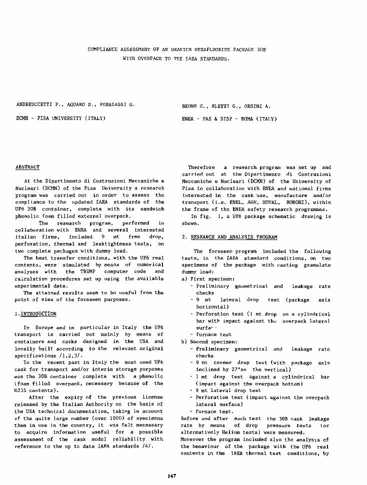
COMPLIANCE ASSESSMENT OF AN URANIUM HEXAFLUORIDE PACKAGE 30B
WITH OVERPACK TO THE IAEA STANDARDS.
ANDREUCCETTI P., AQUARO D., FORASASSI G.
DCMN - PISA UNIVERSITY (ITALY)
BEONE G.( ELETTI G. , ORSINI A.
ENEA - PAS & DISP - ROMA (ITALY)
ABSTRACT
At the Dipartimento di Costruzioni Meccaniche eNucleari (DCMN) of the Pisa University a researchprogram was carried out in order to assess thecompliance to the updated IAEA standards of theUF6 30B container, complete with its sandwichphenolic foam filled external overpack.
The research program, performed incollaboration with ENEA and several interesteditalian firms, included 9 mt free drop,perforation, thermal and leaktightness tests, ontwo complete packages with dummy load.
The heat transfer conditions, with the UF6 realcontents, were simulated by means of numericalanalyses with the TRUMP computer code andcalculation procedures set up using the availableexperimental data.
The attained results seem to be useful from thepoint of view of the foreseen purposes.
1.INTRODUCTION
In Europe and in particular in Italy the UF6transport is carried out mainly by means ofcontainers and casks designed in the USA andlocally built according to the relevant originalspecifications /1,2,3/.
In the recent past in Italy the most used UF6cask for transport and/or interim storage purposeswas the 30B container complete with a phenolic(foam filled overpack, necessary because of theU235 contents).
After the expiry of the previous licensereleased by the Italian Authority on the basis ofthe USA technical documentation, taking in accountof the quite large number (over 1000) of specimensthen in use in the country, it was felt necessaryto acquire information useful for a possibleassessment of the cask model reliability withreference to the up to date IAEA standards lUl.
Therefore a research program was set up andcarried out at the Dipartimento di CostruzioniMeccaniche e Nucleari (DCMN) of the University ofPisa in collaboration with ENEA and national firmsinterested in the cask use, manufacture and/ortransport (i.e. ENEL, AGN, HOVAL, BORGHI), withinthe frame of the ENEA safety research programmes.
In fig. 1, a UF6 package schematic drawing isshown.
2. RESEARCH AND ANALYSIS PROGRAM
The foreseen program included the followingtests, in the IAEA standard conditions, on twospecimens of the package with casting granulatedummy load:
a) First specimen:
- Preliminary geometrical and leakage ratechecks
- 9 mt lateral drop test (package axishorizontal)
- Perforation test (1 mt drop on a cylindricalbar with impact against tho overpack lateralsurfar
- furnace test
b) Second specimen:
- Preliminary geometrical and leakage ratechecks
- 9 mt corner drop test (with package axisinclined by 27°on the vertical)
- 1 mt drop test against a cylindrical bar(impact against the overpack bottom)
- 9 mt lateral drop test- Perforation test (impact against the overpack
lateral surface)
- furnace test.
Before and after each test the 30B cask leakagerate by means of drop pressure tests (oralternatively Helium tests) were measured.Moreover the program included also the analysis ofthe benaviour of the package with the UF6 realcontents in the IAEA thermal test conditions, by
147
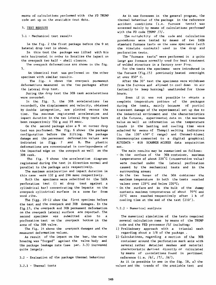
means of calculations performed with the FD TRUMP
code set up on the available test data.
3. TEST RESULTS
3.1 - Mechanical test results
In the fig. 2 the first package before the 9 mtlateral drop test is shown.
In this test the package was lifted with hisaxis horizontal ir. order to localize the impact onthe overpack two half - shell closure.
The overpack deformations are shown in the fig.3.
An identical test was performed on the otherspecimen with similar results.
The fig. 4 shows the overpack permanentdeformations measured on the two packages afterthe lateral drop test.
During the drop test the 30B cask accelerationswere recorded.
In the fig. 5, the 30B accelerations (asrecorded), the displacement and velocity, obtainedby double integration, are plotted versus thetime. The maximum registered acceleration andimpact duration in the two lateral drop tests havebeen respectively 350 g and 19 msec.
On the second package also a 9 mt corner droptest was performed. The fig. 6 shows the packageconfiguration before the lifting. The packagedamage and the permanent deformation values areindicated in figg. 7 and 8. The plasticdeformations are concentrated in corrispondence ofthe impacted edge on the overpack as well as the30B cask.
The fig. 9 shows the acceleration diagramsregistered during the test in direction normal andparallel to the package axis respectively.
The maximum acceleration and impact duration inthis case were 132 g and 296 msec respectively.
Both the specimens were submitted to the IAEAperforation test (1 mt drop test against acylindrical bar) concentrating the impacts on theoverpack cylindrical surface in a zone far fromwood ribs.
The figg. 10-12 show the first specimen beforethe test and the overpack and 30B damages. In thefig.13, the overpack and 30B permanent deformationon the overpack lateral surface are reported. Thesecond specimen was submitted also to aperforation test on the overpack bottom in thearea of the 30B valve.
The fig. 14 shows the overpack damages and themeasured deformation values.
As result of the impact on the bar, the valvehousing was "forged" against the valve body andthe package leakage rate (see par. 3.3) increasedquite largely.
3.2 - Evaluation of the package thermal behaviour
3.2.1 - Thermal tests
As it was foreseen in the general program, thethermal behaviour of the package in the referenceaccident conditions (i.e. furnace tests) wasassessed mainly by means of calculations performedwith the FD code THUMP 111.
The suitability of the code and calculationprocedures were tested by means of two IAEAstandard furnace tests on the same specimens (withthe simulate contents) used in the drop andperforation tests.
The "furnace tests" were performed in a quitelarge gas furnace normally used for heat treatmentof welded structure in a factory near Pisa.
For the tests the specimens were introduced inthe furnace (fig.15) previously heated overnightat over 850° C.
After the 30' test the specimens were withdrawnfrom the furnace and allowed to cool down in air(actually to keep burning) unattended for threehours.
Even if it was not possible to obtain acomplete temperature pattern of the packagesduring the tests, mainly because of partialtransient damage of the experimental set up due tothe industrial enviroment and the characteristicsof the furnace, experimental data on the maximumvalue as well as information on the temperaturetrends in the heating and cooling time wereacheived by means of Thempil melting indicators(in the 120° 430° C range) and Chromel-Alumelthermocouples connected to a digital graphicalAUTODATA - 616 SCANNER ACUREX data acquisitionset.
The main results may be summarized as follows:- On the surface of the 30B container, maximumtemperatures of about 220 C (conservative value)were reached under the lateral perforationcaused by the mechanical tests and in thesurrounding areas;
- On the two bases of the 30B container themaximum temperature in both the tests reachedvalues over 120°C and below 220°C;
- On the surface and in the bulk of the dummycontents maximum temperatures of about 70°C and35°C were reached respectively after 1 h ofcooling time at the end of the test (2101).
1.2.2 - Numerical analysis
The numerical simulation of the tests requiredseveral calculation runs by means of the TRUMPcode and the FED processor /5/ including:
1) Preliminary approach with a triaxial meshregarding about a 1/8 of the package .
2) Calculations, regarding a section of the 30Bcontainer around the perforation mark axis withseveral rather detailed meshes and materialcharacteristic derived directly or calculatedby means of correlations found in pertinentreference (i.e. /6/, HI, /8/).
As it is possible to see in the fig. 16, a) thevalues and the trends of the available test and
148
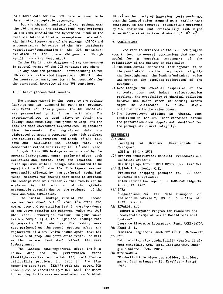
calculated data for the 30B container seem to be
in an rather acceptable agreement.
For the thermal analysis of the package with
the UF6 contents, the calculations were performed
in the same conditions and hypotheses used in the
test simulation with other assumptions related to
the initial temperature of the package (38°C) and
a conservative behaviour of the UF6 (adiabatic
vaporization/condensation in the 30B container;
evolution of the phase changements through
equilibrium situations, etc.).
In the fig.16 b the diagrams of the temperature
in several points of the 30B container are shown.
In any case the pressure, corresponding to the
UF6 maximum calculated temperature (80°C) under
the penetration mark, results to be acceptable for
the structural integrity of the 30B container.
3.3 - Leaktightness Test Results
The damages caused by the tests to the package
leaktigtness was assessed by means air pressure
drop tests. For this purpose, the 30B container
was pressurized up to 1 bar with air. The
experimental set up used allows to obtain the
leakage rate measuring the pressure drop and the
cask and test enviroment temperatures at constant
time increments. The registered data are
elaborated by means a computer code wich performs
the statistic elaboration and check of the test
data and calculates the leakage rate. The
demostrated method sensitivity is 10"^ mbar 1/sec.
In tab. I the 30B leakage rates obtained by the
several leaktightness tests performed after each
mechanical and thermal test are reported. The
first specimen initial leakage rate resulted to be
egual to 1.14 10"^ mbar 1/s. This figure was not
practically affected by the performed mechanical
tests moreover the thermal test seems to decrease
the leakage rate by a factor 2. This result can be
explained by the reduction of the gaskets
microscopic porosity due to the products of the
foam and wood combustion.
The initial leakage rate of the second
specimen was about 5 10~2 jnbar 1/s. After the
corner drop and penetration test in corrispondence
of the valve position the measured value was 19.8
mbar 1/sec. Screwing in further the plug valve
(with a torque egual to 7 Kgm) the leakage rate
decreases to 3.038 mbar 1/s. The leaktightness
test performed on the second specimen after the
replacement of a new valve showed again that the
lateral 9 mt drop and perforation tests, as well
as the furnace test don't affect the cask
leaktigtness.
The leakage rate registered after the 9 m
corner drop and the performation tests
(leaktightness test n.5 in tab. Ill) don't produce
criticallity problems. In fact in the IAEA
immersion test (par. 633/4/) with the actual 30B
inner pressure condition (p = 0.2 bar), the water
in leaching in the cask was evaluated to be about
80 cm^ on the basis of immersion tests performed
with the damaged valve mounted on a smaller test
container. On the contrary calculations performed
by AGN indicated that criticallity risk might
arise with a water in take of about 1,4 10^ cm^.
4. CONCLUSIONS
The results attained in the rp^oarch program
seem to lead to several conclusions that may be
useful for a possible assessment of the
reliability of the package in particular:
1) The most severe mechanical test appears to be
the penetration one that may impair slightly
the leaktightness the loading/unloading valve
and produce the complete perforation of the
overpack.
2) Even though the eventual dispersion of the
contents, does not induce radioprotection
problems, the possibility of chemical pollution
hazards and minor water in-leaching events
might be eliminated by quite simple
modifications to the valve cover.
3) The temperatures attained in thermal test
conditions on the 30B inner container around
the perforation area appear not dangerous for
the package structural integrity.
REFERENCES
ill ANSI
Packaging of Uranium Hexafluoride for
Transport.
ANSI n. 14.1 - 1971
111 Uranium Hexafluoride: Handling Procedures and
container criteria
Oak Ridge op. Off. - ERDA-ORO651 Rev. 4/4/1977
hi Malleh A.J., Hewlon C.E.Protective shipping packages for 30 inch
diameter UF6 cylinders
Uniom Carbide Co. Rep. n. K-1686-Oak Ridge TN
April, 13, 1967
Ihl IAEA"Regulations for the Safe Transport of
Radioactive Material", SS. n. 6 - IAEA Ed.
1973 - Vienna.
Ill EDWARDS, A.L.
"TRUMP: a Computer Program for Transient and
Steadystate Temperatures in Multidimensional
Systems"
Lawrence Livermore Laboratory, Rept. UCRL-14754.
It I PERRY J. B."Chemical Engineers Handbook" 4th Ed.-McGraw Hill
111 CTI
Dati relativi alia conducibilita termica di al-
cuni raateriali. Com. Term. Italiano-Riv. Ener-
gia e Calore - Feb. 1981.
IS/ MISSENARD A.
"Conductivity termique des solides, liquides,
gaz et leur melanges - Ed. Eyrolles - Parigi
1965.
149
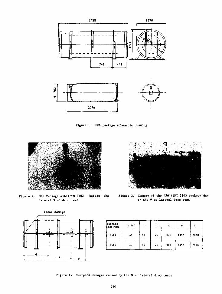
2438 1270
1 ' 1
' 1 1
1.
d
1
1i
1
c
749
i
1
"1
i ! '
i i 'i
_ i
1
448
2070
Figure 1. UF6 package schematic drawing
Figure 2. UF6 Package 4561/BTN 2103 before thelateral 9 mt drop test
Figure 3. Damage of the 4561/BNT 2103 package dueto the 9 mt lateral drop test
local damage
•=#
packagespecimen
4561
4563
a (m)
45
49
b
50
52
c
25
29
d
840
900
e
1450
1655
f
2098
2110
Figure 4. Overpack damages caused by the 9 mt lateral drop tests
150

160 _ 16 _ 48Q_.
,120 -
TEST N.3
o80 "
40 -
X Displacement
o Velocity
Acceleration
14
18
112
Time
1 —16
(msec)
120 24
Figure 5. Acceleration registered during the 9 rat laterial drop test
Figure 6. UF6 Package 4563/BTN 2094 before the 9mt
corner drop test
Figure 7. Overpack damage caused by the 9 mt comerdrop test (package n. 4563/BTN 2094)
Figure 8. Overpack damage caused bythe 9 mt corner droptest (package n. 4563/BTN 2094)
r*ctlon normal
to th« target
151
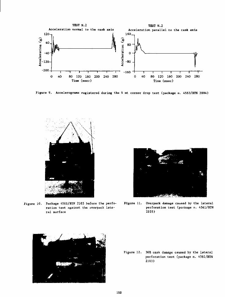
TEST N.2
Acceleration normal to the cask axis
120
TEST N.2Acceleration parallel to the cask axis
160 _
80 ~
0 -
I I I I I I
80 120 160 200 240 280
Tine (msec)
-160 T I I I I I 1
40 80 120 160 200 240 280
Time (msec)
Figure 9. Accelerograms registered (luring the 9 mt corner drop test (package n. 4563/BTN 2094)
Figure 10. Package 4561/BTN 2103 before the perfo-ration test against the overpack late-ral surface
Figure 11. Overpack damage caused by the lateralperforation test (package n. 4561/BTN2103)
Figure 12. 30B cask damage caused by the lateral
perforation test (package n. 4561/BTN
2103)
152
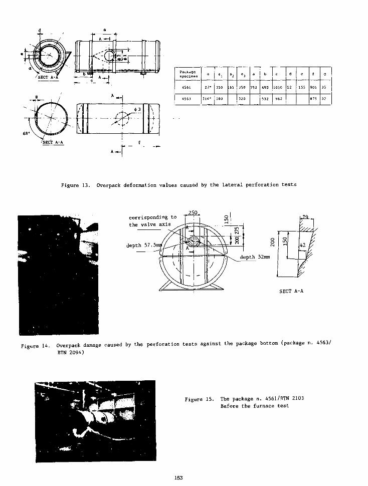
68
/'
\V
43'"^j-
\
I1~r "(
Packagespecimen
4561
4563
°
22-
316°
•l
350
180
*2
.65
43
350
320
a
752
b
490
532
c
1010
962
d
12 155
f
905
875
9
35
32
Figure 13. Overpack deformation values caused by the lateral perforation tests
corrisponding to
the valve axis
depth
depth 52mm
SECT A-A
Figure 14. Overpack damage caused by the perforation tests against the package bottom (package n. 4563/
BTN 2094)
Figure 15. The package n. 4561/BTN 2103
Before the furnace test
153

TCC)
240 -
200 -
160 _
120 _
80 ~
40 ~
0 '
X I Experimental — I Calculated
values — o — values
16—T"40 4824 32 56 64
—r72
t (min)
48 t (min)
Figure 16. Package temperature versus time diagram:
i) Comparisons between experimental and calculated pacages temperaturesb) Simulation of the UF6 real contents: 30B container temperature - time diagram
154
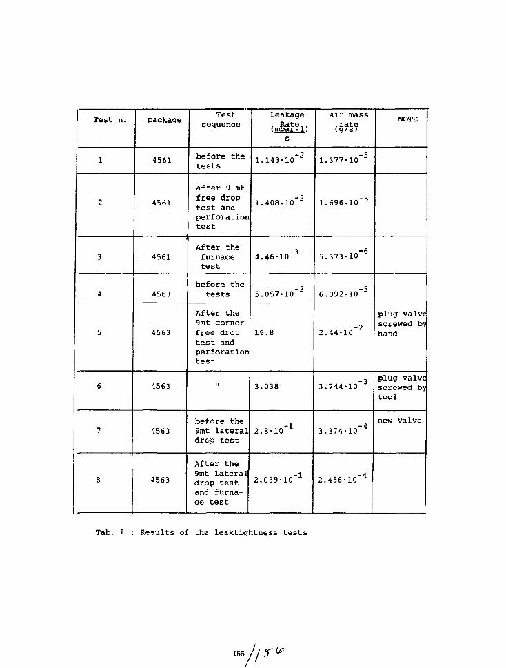
Test n.
1
2
3
4
5
6
7
8
package
4561
4561
4561
4563
4563
4563
4563
4563
Testsequence
before thetests
after 9 mtfree droptest andperforationtest
After thefurnacetest
before thetests
After the9mt cornerfree droptest andperforationtest
ii
before the9mt lateraldrop test
After the9mt lateraldrop testand furna-ce test
Leakage, Rate,.(mbar.l)
s
1.143-10"2
1.408-10"2
4.46-10"3
5.057-10"2
19.8
3.038
2.8-10"1
2.039-10"1
air mass.rate(g/sT
1.377-10"5
1.696-10"5
5.373-10"6
6.092-10"5
2.44-10"2
3.744-10"3
3.374-10"4
2.456-10"4
NOTE
plug valvescrewed byhand
plug valvescrewed bjtool
new valve
Tab. I : Results of the leaktightness tests
155 //
UPDATE ON PACKAGING FOR URANIUM HEXAFLUORIDE TRANSPORT
W. A. Pryor
Department of EnergyOak Ridge Operations
Oak Ridge, Tennessee 37830 USA(Retired)
ABSTRACT
The slightly enriched product UFs shipped fromthe enriching plants for the world's nuclearpower plants must be protected in order toconform to domestic and international transportregulations. The principal overpack currentlyin use is the U. S. Department of Transportation(DOT) Specification 21PF-1 which protects Model30 UFc cylinders (Title 49, Code of FederalRegulations; Part 178.121, Specification 21PF-1;Fire and Shock Resistant, Phenolic - FoamInsulated Overpack [Horizontal Loading]).Operational problems have developed due both todesign and lack of maintenance, resulting in theentry of water into the insulation zone.Following major review of these problems,particularly those concerned with water entryand general deterioration, design modificationshave been proposed. These modifications forexisting overpacks are to be made only after anywater absorbed within the phenolic foaminsulation is reduced to an acceptable level.New overpacks will be fabricated under anenhanced design. Existing overpacks which aremodified will be designated as 21PF-1A while newoverpacks fabricated to the enhanced design willbe designated as 21PF-1B. In both cases,proposed quality assurance/control requirementsin the fabrication, modification, use andmaintenance of the overpacks are applicable tofabricators, modifiers, owners and users. Acomposite report describing the proposal hasbeen prepared.
INTRODUCTION
In order to meet the packaging requirements ofdomestic and International Atomic Energy Agency(IAEA) transport regulations, the cylinders ofslightly enriched UF5 shipped from the world'senriching plants are contained within overpacks.The 21PF-1 overpacks have been utilized toprovide the required mechanical and thermalprotection. A prototype which was subjected tothe hypothetical accident test series in themid-1960s, successfully provided the necessaryprotection. After being specified as a DOTspecification package, it has been accepted forworld-wide use. The current design of the 21PF-
1 overpack has features which require inspectionand maintenance. These features include metalcomponents fabricated of carbon steel and a non-metal covered closure interface of wood whichsteps down from outside to inside. When routinemaintenance is not provided, the combination ofwarping of the wood in the step-joint andcorrosion of the carbon steel permits water toenter the insulation cavity. The process isaccelerated due to exposure to the moist,corrosive atmosphere during transport on sea-going vessels. In 1984, the U. S. Department ofEnergy (DOE) filed a petition for change to theDOT regulations to modify the design of the21PF-1 overpacks. The Notice of ProposedRulemaking was published as a Notice in the U.S. Federal Register. The modifications were toapply to existing overpacks as well as overpacksfabricated in the future. Since 1984, there hasbeen additional testing to assure that theinsulation in the existing overpacks aftermoisture removal provides the requiredprotection. Subsequent design improvements havebeen submitted by the DOE to the DOT for thefinal rulemaking. The DOE is also proposingmandatory quality assurance/control requirementsfor the fabrication, modification, use, andmaintenance of the 21PF-1 overpacks. Acomposite proposal was submitted to DOT by DOEin August 1987.1 DOE recommended that theproposal be published in the Federal Register asa DOT final rule.
(This final rule had not been published at thetime this paper was prepared; however, itspublication is expected to be early in 1988.)
MODIFICATIONS TO U. S. DEPARTMENT OFTRANSPORTATION SPECIFICATION 21PF-1 OVERPACKS
The modifications of the 21PF-1 overpack designare basically to upgrade and enhance previouslyfabricated and new overpacks to provideregulatory protection to the contained cylindersof UFg and to minimize routine maintenance. Inorder to assure that the fabrication andmodifications are made as specified and that theoverpacks are maintained, the DOE is proposingmandatory quality assurance/control requirementswhich cover the fabrication, modification, use,and maintenance of the 21PF-1 overpacks. Theserequirements would apply to fabricators,modifiers, owners, and users. Thus, domesticfabricators and modifiers would be required tohave a U. S. Nuclear Regulatory Commission (NRC)approved quality assurance program. Owners andusers would also be required to have an NRCapproved or equivalent program. (At the timethis paper was published, DOT was considerirq
157
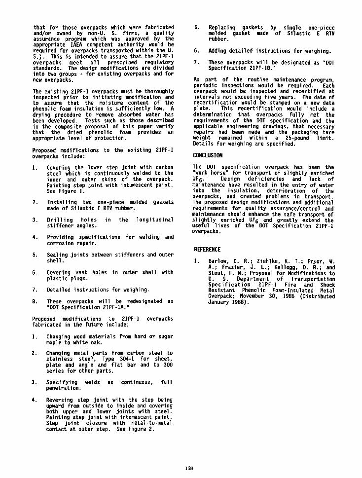
that for those overpacks which were fabricatedand/or owned by non-U. S. firms, a qualityassurance program which was approved by theappropriate IAEA competent authority would berequired for overpacks transported within the U.S.). This is intended to assure that the 21PF-1overpacks meet all prescribed regulatorystandards. The design modifications are dividedinto two groups - for existing overpacks and fornew overpacks.
The existing 21PF-1 overpacks must be thoroughlyinspected prior to initiating modification andto assure that the moisture content of thephenolic foam insulation is sufficiently low. Adrying procedure to remove absorbed water hasbeen developed. Tests such as those describedin the composite proposal of this paper verifythat the dried phenolic foam provides anappropriate level of protection.
Proposed modifications to the existing 21PF-1overpacks include:
1.
2.
3.
4.
5.
6.
7.
8.
Covering the lower step joint with carbonsteel which is continuously welded to theinner and outer skins of the overpack.Painting step joint with intumescent paint.See Figure 1.
Installing two one-piece molded gasketsmade of Silastic E RTV rubber.
Drilling holesstiffener angles.
in the longitudinal
Providing specifications for welding andcorrosion repair.
Sealing joints between stiffeners and outershell.
Covering vent holes in outer shell withplastic plugs.
Detailed instructions for weighing.
These overpacks will be redesignated as"DOT Specification 21PF-1A."
Proposed modifications to 21PF-1 overpacksfabricated in the future include:
1. Changing wood materials from hard or sugarmaple to white oak.
2. Changing metal parts from carbon steel tostainless steel, Type 304-L for sheet,plate and angle and flat bar and to 300series for other parts.
3. Specifying welds as continuous, fullpenetration.
4. Reversing step joint with the step beingupward from outside to inside and coveringboth upper and lower joints with steel.Painting step joint with intumescent paint.Step joint closure with metal-to-metalcontact at outer step. See Figure 2.
5. Replacing gaskets by single one-piecemolded gasket made of Silastic E RTVrubber.
6. Adding detailed Instructions for weighing.
7. These overpacks will be designated as "DOTSpecification 21PF-1B."
As part of the routine maintenance program,periodic inspections would be required. Eachoverpack would be inspected and recertified atintervals not exceeding five years. The date ofrecertification would be stamped on a new dataplate. This recertification would include adetermination that overpacks fully met therequirements of the DOT specification and theapplicable engineering drawings, that necessaryrepairs had been made and the packaging tareweight remained within a 25-pound limit.Details for weighing are specified.
CONCLUSION
The DOT specification overpack has been the"work horse" for transport of slightly enrichedUFg. Design deficiencies and lack ofmaintenance have resulted in the entry of waterinto the insulation, deterioration of theoverpacks, and created problems in transport.The proposed design modifications and additionalrequirements for quality assurance/control andmaintenance should enhance the safe transport ofslightly enriched UFg and greatly extend theuseful lives of the DOT Specification 21PF-1overpacks.
REFERENCE
1. Barlow, C. R.; Ziehlke, K. T . ; Pryor, H.A.; Frazier, J . L.; Kellogg, D. R.; andStout, F. W.; Proposal for Modifications toU. S. Department of TransportationSpec i f i ca t ion 21PF-1 Fire and ShockResistant Phenolic Foam-Insulated MetalOverpack; November 30, 1986 (DistributedJanuary 1988).
158
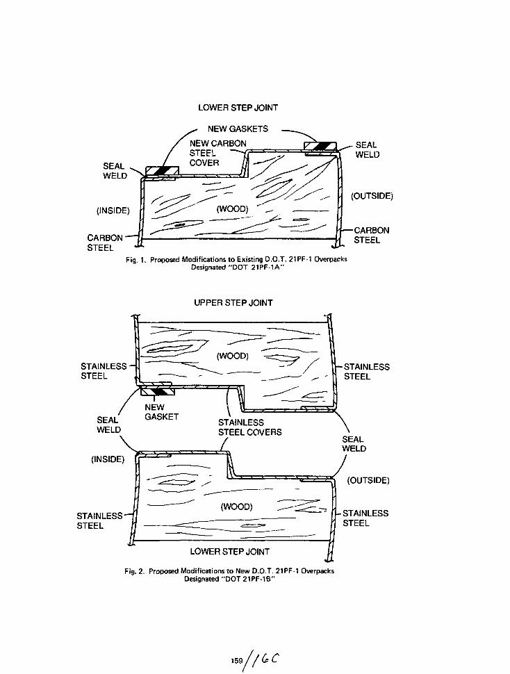
LOWER STEP JOINT
NEW GASKETS
SEALWELD
(INSIDE)
CARBON -STEEL «**•
NEW CARBONSTEFLCOVER
SEALWELD
(OUTSIDE)
1—CARBONSTEEL
Fig. 1. Proposed Modifications to Existing D.O.T. 21PF-1 OverpacksDesignated "DOT 21PF-1A"
UPPER STEP JOINT
STAINLESS -STEEL
SEALWELD
(INSIDE)
STAINLESSSTEEL
NEWGASKET
STAINLESSSTEEL COVERS
STAINLESSSTEEL
\SEW
JSEALWELD
(OUTSIDE)
I-STAINLESSSTEEL
LOWER STEP JOINT
Fig. 2. Proposed Modifications to New D.O.T. 21PF-1 OverpacksDesignated "DOT 21PF-1B"
159

THERMAL PROPERTIES EVALUATION OFUF6 CYLINDER OVERPACK INSULATION
James Lanny FrazierDevelopment EngineerMartin Marietta Energy Systems, Inc.Oak Ridge Gaseous Diffusion PlantOak Ridge, TN
ABSTRACT
A phenolic foam is incorporated into the design andconstruction of UFg cylinder shipping containersknown as overpacks. The overpack provides mechani-cal and thermal protection to UFg product cylindersduring transport. The phenolic foam is utilized forthermal insulation. An important criterion inoverpack design is to limit temperature excursionsof the product cylinder below the triple point ofUFg, preventing possible overpressurization of thecylinder. A current requirement is that the productcylinder wall temperature be maintained below theUFg triple point with the outer surfaces of theoverpack exposed to 1475T for thirty minutes. Apossible heat source is the close proximity of afire. Overpack thermal protection design requiresthermal properties data for the materials ofconstruction, particularly for the phenolic foaminsulation which provides the primary thermalresistance. Thermal conductivity and heat capacitydata for the phenolic foam are limited in theliterature. Accurate heat transfer models of theoverpack require thermal properties spanning therange from room temperature to 1475°F. An ex-perimental program was devised to measure thethermal conductivity and heat capacity of theinsulating foam over the temperature span ofinterest.
TEXT
Enriched uranium in the form of solid uraniumhexafluoride is transported in interstate andinternational shipments in cylinders which areenclosed within an insulated, protective overpack.Protective overpacks have been in service for anumber of years with the intervening introductionof minor design modifications. Environmental andsafety requirements have dictated additionaltesting, analysis, and evaluation of overpack designand construction related to possible accidentscenarios. The phenolic foam insulating materialwhich is encased within a wood reinforced shellassembly forming the overpack is an integral part ofthe uranium hexafluoride cylinder protection. Theinsulation barrier provides a measure of mechanicalshock isolation in addition to its primary functionof serving as a thermal resistance to possible heatsources to which a product cylinder might beexposed during transport. Properties of theinsulating foam are necessary in order to determineboth mechanical and thermal functions of the
material. Thermal properties of the insulation arenecessary for incorporation into heat transferanalyses of the overpack subjected to known orassumed thermal loads. The properties of soliduranium hexafluoride dictate design requirements forthe overpack in terms of thermal protection;reasonable means must be provided in order toprevent the triple point temperature of the productfrom being attained. Should the triple pointtemperature be reached, overpressurization of thecontainment cylinder could occur with the pos-sibility of a breach with an accompanying environ-mental insult. The phenolic foam is required tofunction over a temperature range of approximately1400°F; a temperature range which could be producedby a close proximity fire. The insulating foam isarranged In an annular ring around the productcylinder with end closures. Temperatures in theinsulation will vary with radial location duringoverpack exposure to a transient thermal excursion;therefore, it is important to determine thermalproperties of the insulation at various temperaturesever the range of interest. The determination ofthe temperature correlation of thermal propertieswill enhance analytical thermal models which may bedeveloped.
EXPERIMENTAL PROCEDURE
Thermal properties of interest to the development ofanalytical heat transfer models are thermalconductivity and specific heat capacity. Thethermal conductivity of the overpack phenolic foamwas measured using an apparatus conforming to therequirements of the American Society for Testing andMaterials (ASTM), Standard C177, Standard Method ofTest for Thermal Conductivity of Materials by Meansof the Guarded Hot Plate. This test method isrecommended for insulating materials over a largerange of temperatures for the condition of steadystate heat flow. The method consists of generatingaxial heat flow through two samples of the materialto be tested, placed on either side of a known heausource. Auxiliary heat sources provide isothermalsample cold surface temperatures while additionalcontrolled heaters and insulation reduce radial heatlosses from the test stack assembly to acceptablelevels. The method consists of achieving steadystate conditions in the test assembly, measuring thetemperature gradient across a known sample thicknessand determining the heat flow generated in the teststack assembly. The thermal conductivity of ahomogeneous material is defined as the time rate ofheat flow through unit area per unit temperature
161
gradient in the direction perpendicular to anisothermal surface. Eight-inch diameter, one-halfinch thick disk samples of the phenolic foam weretested in a nitrogen atmosphere at mean sampletemperatures to 1285°F.
The specific heat capacity of the phenolic foamoverpack insulation was determined by means of themethod of "drop calorimetry". The heat required toraise the temperature of a unit mass of material byone degree is the heat capacity at constantpressure. The specific heat capacity is expressedin terms of calories per gram per °F.
The drop method can be utilized to measure heatcapacity or heats of fusion of transition. A sampleis dropped from a hot furnace at a known elevatedtemperature into a calorimeter maintained at someknown, lower temperature. THe heat absorbed by thecalorimeter is equal to the difference in heatcontent between the initial sample temperatures andthe final sample temperature. The configuration ofthe calorimeter was such that the device functionedas a isothermal water calorimeter; whereby, thecalorimeter proper is surrounded by a constanttemperature jacket. The calorimeter consisted of adewar flask equipped with electric stirrers tomaintain a constant 25°C water bath temperature.The dewar vessel was surrounded by foam Insulationin order to prevent heat exchange from the outerdewar wall to atmosphere. An elevated temperaturefurnace was mounted on supports above the calori-meter bath, and the furnace was capable of obtainingtemperatures of ~1800°F. A calorimetry experimentconsisted of elevating the temperature of the sampleto 1475°F, dropping the sample into the calorimeter,and measuring the temperature increase of the knownwater mass as a function of time. The specific heatcapacity of the phenolic foam could be then computedfrom the measured temperature rise of the calori-meter fluid.
RESULTS
The thermal conductivity of the phenolic foamincreases with increasing temperature, exhibiting anapproximately linear relationship to 1000°F. A non-steady state value at mean sample temperature of
1285°F revealed a significantly higher thermalconductivity and a deviation from the lineartemperature thermal conductivity relationshipobtained from room temperature to 1000°F. Thehigher thermal conductivity at temperaturesexceeding 1000°F is attributable to compositionalchanges in the material and to an increase in therelative contribution from the mechanism of radia-tive heat transfer at the higher temperatures.Measured thermal conductivities ranged from 0.020Btu-ft/h-ft2-°F at 145°F to 0.070 btu-ft/h-£t2-°F at1000°F. The transient test at 1285°F indicated athermal conductivity of 0.154 Btu-ft/h-f2-°F.
The specific heat capacity for the phenolic foam atan initial temperature of 1475°F for five samplestested ranged from 0.093 calories/gm/°F to 0.106calories/gm/°F. The experimentally measured thermalproperties of the phenolic foam are presented forincorporation into heat transfer models of theoverpack container.
FOLLOW ON ACTIVITIES
Thermal Conductivity
1. Additional testing to determine statisticalvariance.
2. Determine effects of material decomposition onthermal conductivity and structural integrity,particularly at temperatures exceeding 1000°F.Time at temperature in an oxidizing atmosphereis postulated as being a primary factor relatedto decomposition of the phenolic foam insula-tion.
3. Determine the efforts of material anisotropy onthermal conductivity.
Specific Heat Capacity
1. Refine measurement technique and utilize othermethods for comparison.
2. Determine specific heat temperature correlationsfor the phenolic foam material.
Praoarad by 11M 0 * Ridga G w o a DKIuHon Plant.0 * Rldje. T n a m 37831. oparalad by MARTINMARIETTA ENERGY SYSTEMS. INCORPORATED,tor th» U.S. DEPARTMENT OF ENERGY, imOarContract No. 0E-AC0544OR2T4O}.
The submktad manuscript hm baart authorad by *contractor of the U.S. Govarnmant undar Confract No.DEAC05S4OR2U00. Accordingly. tha U.S.Govsrnmant retain* • nonaictutlva. royalty-traelicensa to publish or raproduca tha puoriihad form olthis contribution, or allow othara to do *o. lor U.S.Gcvammant PurpoMa.
162
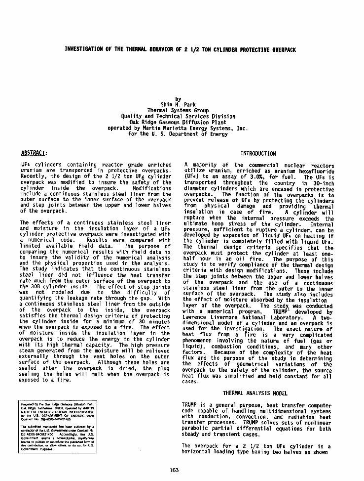
INVESTIGATION OF THE THERMAL BEHAVIOR OF 2 1/2 TON CYLINDER PROTECTIVE OVERPACK
byShin H. Park
Thermal Systems GroupQuality and Technical Services Division
Oak Ridge Gaseous Diffusion Plantoperated by Martin Marietta Energy Systems, Inc.
for the U. S. Department of Energy
ABSTRACT:
UF6 cylinders containing reactor grade enricheduranium are transported in protective overpacks.Recently, the design of the 2 1/2 ton UFg cylinderoverpack was modified to insure the safety of thecylinder inside the overpack. Modificationsinclude a continuous stainless steel liner from theouter surface to the inner surface of the overpackand step joints between the upper and lower halvesof the overpack.
The effects of a continuous stainless steel linerand moisture in the insulation layer of a UF6cylinder protective overpack were investigated witha numerical code. Results were compared withlimited available field data. The purpose ofcomparing the numerical results with field data isto insure the validity of the numerical analysisand the physical properties used in the analysis.The study indicates that the continuous stainlesssteel liner did not influence the heat transferrate much from the outer surface of the overpack tothe 30B cylinder inside. The effect of step jointswas not modeled due to the difficulty ofquantifying the leakage rate through the gap. Witha continuous stainless steel liner from the outsideof the overpack to the inside, the overpacksatisfies the thermal design criteria of protectingthe cylinder inside for a minimum of 30 minuteswhen the overpack is exposed to a fire. The effectof moisture inside the insulation layer in theoverpack is to reduce the energy to the cylinderwith its high thermal capacity. The high pressuresteam generated from the moisture will be relievedexternally through the vent holes on the outersurface of the overpack. Although these holes aresealed after the overpack is dried, the plugsealing the holes will melt when the overpack isexposed to a fire.
Prepared by the 0 * Ridge Gaseous Dffiutkxi Plant.Oak Ridge. Tennessee 37831. operated by MARTINMARIETTA ENERGY SYSTEMS. INCORPORATED,(or the U.S. DEPARTMENT OF ENERGY, underContract No. DE-ACO5-MOR2M00
The submtted manuscript has bawl authored by acontractor of the U.S. Govammant under Contract No.0E-AC05-84OR2U00. Accordingly, lha U.S.Government retains a nonexclusive, royalty-freelicense to publish or reproduce the published form ofthis contribution, or allow others to do so. lor U.S.Government Purposes.
INTRODUCTION
A majority of the commercial nuclear reactorsutilize uranium, enriched as uranium hexafluoride(UFe) to an assay of 3.0%, for fuel. The UFe istransported throughout the country in 30-inchdiameter cylinders which are encased in protectiveoverpacks. The function of the overpacks is toprevent release of UFe by protecting the cylindersfrom physical damage and providing thermalinsulation in case of fire. A cylinder willrupture when the internal pressure exceeds theultimate hoop stress of the cylinder. Internalpressure, sufficient to rupture a cylinder, can bedeveloped by expansion of liquid UFs on heating ifthe cylinder is completely filled with liquid UFs.The thermal design criteria specifies that theoverpack must protect the cylinder at least one-half hour in an oil fire. The purpose of thisstudy is to verify compliance of the thermal designcriteria with design modifications. These includethe step joints between the upper and lower halvesof the overpack and the use of a continuousstainless steel liner from the outer to the innersurface of the overpack. The study also includesthe effect of moisture absorbed by the insulationlayer of the overpack. The study was conductedwith a numerical program, TRUMP developed byLawrence Livermore National Laboratory. A two-dimensional model of a cylinder and an overpack isused for the investigation. The exact nature ofheat flux from a fire is a very complicatedphenomenon involving the nature of fuel (gas orliquid), combustion conditions, and many otherfactors. Because of the complexity of the heatflux and the purpose of the study in determiningthe effects of geometrical variations of theoverpack to the safety of the cylinder, the sourceheat flux was simplified and held constant for allcases.
THERMAL ANALYSIS MODEL
TRUMP is a general purpose, heat transfer computercode capable of handling multidimensional systemswith conduction, convection, and radiation heattransfer processes. TRUMP solves sets of nonlinearparabolic partial differential equations for bothsteady and transient cases.
The overpack for a 2 1/2 ton UFs cylinder is ahorizontal loading type having two halves as shown
163

Fig. 1. 2-1/2 ton UFg cylinder overpack - horizontal loading type.
in Fig. 1. A two-dimensional model, shown in Fig.2, was used to investigate the temperature profilesof a prototype cylinder in cases where flamessurrounded the overpack. The solid We mass insidea cylinder was assumed to be deposited radially inuniform thickness layers Inward from the cylinderwall to simplify the analysis. In the case of afull cylinder, solid UF6 occupies more than 60% ofthe internal surface of a cylinder, which makesthis simplification close to the real situation.The heat flux from a fire to an overpack is the sumof the radiative and convective heat transferprocesses, and is expressed as
q - A * [Fi2*(Tf4-Ts
4) + hc(Tf- Ts)]
where F12 is the overall exchange factor, hc is thenatural convective heat transfer coefficient, andTf and Ts, are the temperatures of the fire and thesurface of the overpack, respectively. Thecylinder surface temperature, TQ, will be the mainobservation point in the analysis. The heatexchange between the inner surface of an overpackand the outer surface of the cylinder is byradiation only. The initial temperature of theoverpack system is 80 F. To simulate exposure to afire, the overpack was suddenly exposed to a gasenvironment with an average temperature of 1,750 F.The gas emissivity used was 0.5. The effect ofmoisture in the insulating layer was analyzed byassuming that the total moisture content isconcentrated in the middle of the insulation layer
as shown in Fig. 3. Since the primary purpose ofthe investigation was to determine the temperaturesof the cylinder and UFs, the assumption did notintroduce any gross error into the final analysis.For analysis of the worst case, an overpack isassumed to be engulfed in fire.
RESULTS
The effectiveness of the overpack in meeting thethermal design criteria was investigated with thetwo-dimensional model. The worst case consideredwas an infinitely large fire source with theflames surrounding the entire overpack. Theresults of this case are compared in Fig. 4 withexperimental data obtained by the Oak Ridge GaseousDiffusion Plant (ORGDP) in 1966 . The agreementbetween the analytical and experimental results isfairly good considering the uncertainties thatexist in experimental conditions. The cylindersurface temperature at the mid-section by theanalysis is approximately 122 F after one hour inthe fire even though the outside surface of theoverpack is at 1,742 F. Furthermore, the UF6temperature inside the cylinder is below the triplepoint temperature. Even if the higher values ofthe experimental data are chosen, the cylindersurface temperature after one-half hour in the firewould be below the triple point temperature of UFe.This indicates that the overpack meets the thermaldesign criteria of protecting the cylinder for one-half hour when exposed to a fire.
164

DWG. NO. K/G-tS-ia40-lt1
T G
• Jr.
STEPJOINT'
STAINLESS STEELS
STAINLESS STEEL.
STEEL
mtmm
OVERPACK
UF 6 CYLINDER
OVERPACK
Fig. 2. Model of cylinder and protective overpack.
INSULATION
DWG. NO.(U)
STAINLESS STEEL -i
STAINLESS STEEL
STEEL
OVERPACK
UFR CYLINDER
OVERPACK
Fig. 3. Model of cylinder and protective overpack with moisture.
165

OWC. NO. K/S-U-4tM
1000
100
i i i i-
I ORGDP TEST RESULT11
SW::!::¥:::¥S::"::JS:::5:::S
1 +
mmMmmfm*
10 1 1 I I 1 I I { I I I l__l I I I I I I I I0.01 0.1 1 - 10
TIME, hr
Fig. 4. Radial temperature variation at mid-section of the overpack with time in fire.
The phenolic foam used in overpacks was manufac-tured based on some physical specifications such asdensity, porosity, etc., but no thermal propertyspecifications. Since there was no record of ameasured thermal conductivity value, a conductivityvalue that best fit the existing test results wasobtained. Hence, a thermal conductivity value of0.170 Btu/hr ft F was used in this analysis, whichwas the best fit to the existing data . Thevalidity of the code and other physical propertiesused in the code are proven in Fig. 5, where thetemperature profile through the ends, whose thermalconductivity value is known, agreed well with theexperimental value. The thermal conductivity valuereported by Frazier , however, was one order ofmagnitude lower than the value used in the analysisat room temperature, but was comparable attemperatures above 1,000 F. The temperatureprofile of the overpack with temperature dependentthermal conductivity by Frazier was plotted in Fig.6 along with the constant thermal conductivity of0.170 Btu/hr ft F and ORGDP experimental value.The overpack temperature profile with the constantthermal conductivity case in the cylinder safetystudy. The temperature profiles with both thermalconductivity values satisfy the thermal designcriteria.
The effectiveness of the overpack step joint inlimiting the cylinder wall temperature rise willdepend entirely upon the leakage rate of hot flumethrough the gap which is difficult to quantify.
Theoretically the step joint will be more effectivethan the straight joint in terms of reducing theleakage rate of hot flume from the fire. Inaddition, the step joints between the two halves ofthe overpack would provide a more solid connectionstructurally. Therefore, there is no quantitativecriteria of leakage rate through the gap inintroducing the step joint. Thermal analysis ofthe step joint was not performed. The effect of acontinuous stainless steel liner from the outer tothe inner surface of the overpack was examined, butthis effect is minimal, as shown in Fig. 7. Theliner is 14 gauge stainless steel, and the heattransfer rate through this cross section is smallcompared to that through the insulation layer.
The effect of moisture in the insulation layer ofthe overpack was investigated with the model shownin Fig. 3. There are 40 vent holes on the outersurface of overpack. During the overpack construc-tion process, a fully assembled overpack is driedin an oven to drive away any moisture contained inthe insulation layer of the overpack. When anoverpack is dried, the vent holes are covered witha plastic plug to make it moisture proof. But theinsulation layer of an overpack absorbs moistureduring long years of service, thereby changing thethermal properties of the insulation material. Inthis analysis, a total of 200 pounds of moisturewas assumed to be absorbed by the insulation layer,even though the amount of moisture absorbed by thephenolic foam varied widely. The 200 pounds used
166
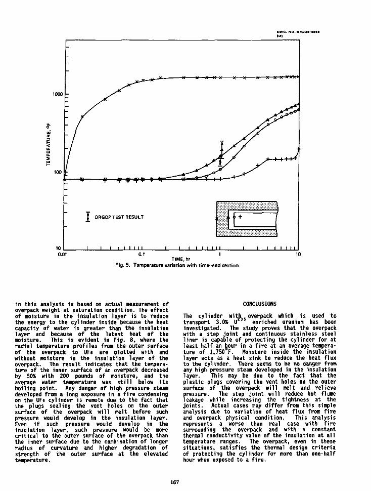
DWG. NO. K/G-IS-4M *(Ul
1000
UJa.
100
* * •
fr-H
I ORGDP TEST RESULT u +
100.01 0.1 1
TIME, hrFig. 5. Temperature variation with time-end section.
10
in this analysis is based on actual measurement ofoverpack weight at saturation condition. The effectof moisture in the insulation layer is to reducethe energy to the cylinder inside because the heatcapacity of water is greater than the insulationlayer and because of the latent heat of themoisture. This is evident in Fig. 8, where theradial temperature profiles from the outer surfaceof the overpack to UFs are plotted with andwithout moisture in the insulation layer of theoverpack. The result indicates that the tempera-ture of the inner surface of an overpack decreasedby 50% with 200 pounds of moisture, and theaverage water temperature was still below itsboiling point. Any danger of high pressure steamdeveloped from a long exposure in a fire condensingon the UFe cylinder is remote due to the fact thatthe plugs sealing the vent holes on the outersurface of the overpack will melt before suchpressure would develop in the insulation layer.Even if such pressure would develop in theinsulation layer, such pressure would be morecritical to the outer surface of the overpack thanthe inner surface due to the combination of longerradius of curvature and higher degradation ofstrength of the outer surface at the elevatedtemperature.
CONCLUSIONS
The cylinder with overpack which is used totransport 3.0% U enriched uranium has beeninvestigated. The study proves that the overpackwith a step joint and continuous stainless steelliner is capable of protecting the cylinder for atleast half an hour in a fire at an average tempera-ture of 1,750 F. Moisture inside the insulationlayer acts as a heat sink to reduce the heat fluxto the cylinder. There seems to be no danger fromany high pressure steam developed in the insulationlayer. This may be due to the fact that theplastic plugs covering the vent holes on the outersurface of the overpack will melt and relievepressure. The step joint will reduce hot flumeleakage while increasing the tightness at thejoints. Actual cases may differ from this simpleanalysis due to variation of heat flux from fireand overpack physical condition. This analysisrepresents a worse than real case with firesurrounding the overpack and with a constantthermal conductivity value of the insulation at alltemperature ranges. The overpack, even in thesesituations, satisfies the thermal design criteriaof protecting the cylinder for more than one-halfhour when exposed to a fire.
167

DWG. NO. K/G-M-IMI
1000
cc3<
INSULATION THERMAL CONDUCTIVITY
A k, = 0.170 Btu/hr ft °F
O l<2 = 0.00553 t +0.0125Btu/hr ft °F (3)tin°F
T ORGDP EXPERIMFNTAL DATA
100
40 I I
I
o a.
I IJ 111« a<= z
Fig. 6. Variation of temperature profile with thermalconductivity of insulating material.
168
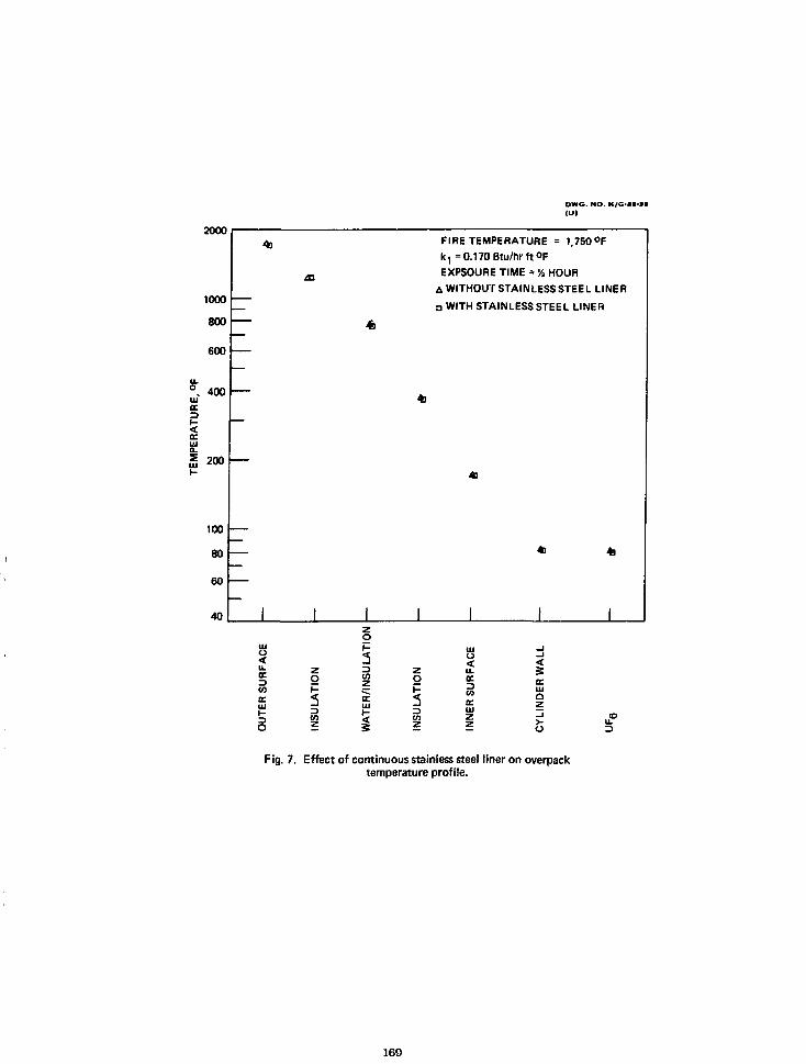
DWG. NO. K/G-aS-3*
3-uj< r> -tc
iUJ-
2UUU
1000
800
600
400
200
100
80
60
40
49
I
43
I
49
I
FIRE TEMPERATURE = 1,750°Fk , = 0.170 Btu/hr ft OF
EXPSOURE TIME = V, HOUR
A WITHOUT STAINLESS STEEL LINER
a WITH STAINLESS STEEL LINER
4]
m
* 49
I I I I
o
a.a.u>
UJ
O
Oz
UJ
o5
<u.IE00IE
IIEUJQZ
Fig. 7. Effect of continuous stainless steel liner on overpacktemperature profile.
169
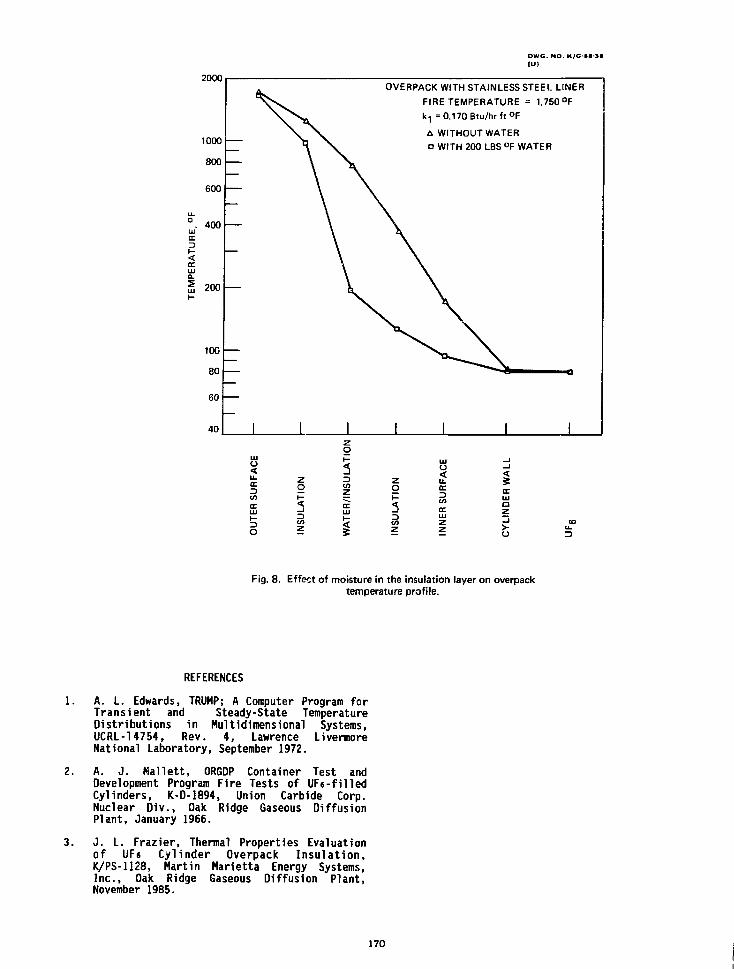
DWC NO. K/G-SS-3S
IU)
UJDC3
2000
1000
800
600
400
<
UJ
200
10G
80
60
40
OVERPACK WITH STAINLESS STEEL LINER
FIRE TEMPERATURE = 1,750 °F
k-, = 0.170 Btu/hr ft °F
A WITHOUT WATER• WITH 200 LBS °F WATER
<u.
o
o
o
Ito
o<u.3toIT
irUJa
O
Fig. 8. Effect of moisture in the insulation layer on overpacktemperature profile.
REFERENCES
1. A. L. Edwards, TRUMP; A Computer Program forTransient and Steady-State TemperatureDistributions in Multidimensional Systems,UCRL-14754, Rev. 4, Lawrence LivermoreNational Laboratory, September 1972.
2. A. J. Mallett, ORGDP Container Test andDevelopment Program Fire Tests of UF6-filledCylinders, K-D-1894, Union Carbide Corp.Nuclear Div., Oak Ridge Gaseous DiffusionPlant, January 1966.
3. J. L. Frazier, Thermal Properties Evaluationof UF6 Cylinder Overpack Insulation,K/PS-1128, Martin Marietta Energy Systems,Inc., Oak Ridge Gaseous Diffusion Plant,November 1985.
170

ONE-INCH UF, CYLINDER VALVE FAILURE
S. C. Blue and J. H. AldersonMartin Marietta Energy Systems, Inc.
Paducah Gaseous Diffusion PlantPaducah, Kentucky
ABSTRACT
Defects In one-Inch cylinder valves procured foruse In uranium hexafiuoride (UFt) cylinders werediscovered during Installation.
The defects were detected by soap testing of thevalves and cylinders. The Investigation detectedsimilar problems In other production runs by thesame manufacturer. This paper covers the Investi-gation of the original problem, evaluation of thedefects, notification of all concerned parties,Interim solution, and corrective actions taken toeliminate this problem.
INTRODUCTION
The Paducah Plant, Martin Marietta Energy Systems,Inc., procures one-Inch angle valves forInstallation In cylinders that are used forstorage and transportation of uranium hexafluo,-1de(UF t). In June 1986, a contract was awarded tothe Superior Valve Co., Washington, Pennsylvania,for 2694 valves. After delivery had started InMarch 1987, the Paducah Plant began to forwardvalves to the fabricator of new tails cylindersand to the Portsmouth Plant for normal Inventoryrequirements. In July, the fabricator discoveredthat two valves from forging heat lot 20 wereleaking after Installation Into cylindercouplings.
INVESTIGATION
The materials laboratory at the Paducah plantbegan an investigation of the cracked valves.When five additional fractures, from forging Heats17 and 20, were discovered, the manufacturer wasInformed of the Incidents; and the PortsmouthPlant and cylinder fabricator were notified thatvalves from Heats 17 and 20 were not to be used.The Department of Energy (DOE) was notified of thefailures, and they subsequently contacted the
Prapaiad by » » Paducah G w u DMutkn PUM.Paducan, Kanucky 42001. opaoaad by MARTINMARIETTA ENERGY SYSTEMS. INCORPORATED,to • » U.S- DEPARTMENT OF ENERGY, wdarCamel No. DE-AC0M4OR2U00.
Tha lubmttad manuicrtpl rua baan autfwrad by •axttacur d tha US. aovarnnant undar Cor*a3 No.DE-AC05-MOR21400. Accordingly. Iha U.S.Govammant retain* a nonaxdullva, royalty-iraat a n 10 puMkh or mnoOuca « " puMtM torn olthis contribution, or allow orhar* to do to. for U.S.Govammant Pufpoaaa.
Nuclear Regulatory Commission (NRC) so that theirlicensees would be aware of the problem. Thescope of the Investigation was expanded to includeassistance from other diffusion plants and OakRidge National Laboratory (ORNL). The valvemanufacturer and the forging plant also InitiatedIndependent Investigations.
The Paducah Plant investigated the reliability ofother forging lots by Installing valves from Heats18, 19, and 21 Into cylinders and leak testingwith 100 psi air. After a valve from Heat 19broke off during Installation, all valves fromHeats 17 through 22 were considered suspect; and ahold was put on their use. The valves could notbe put Into a cylinder, and any cylinder with asuspect valve could not be filled or fed until thevalve was changed. Initially, the suspect groupincluded valves from Heat 16 because one from thatgroup had been Included In the 1987 delivery.However, 1t was determined that Heat 16 forgingshad been produced at an earlier date and that noproblems had been encountered with valves machinedfrom production related forgings.
Preliminary Information from the Paducahlaboratory and ORNL Indicated that highconcentrations of aluminum were present onfracture faces. It was suspected that segregationof aluminum could have occurred before the bodieswere forged. Visits to the bronze mill, forgingplant, and valve manufacturer were planned todiscuss preliminary findings, observemanufacturing methods, and review qualityassurance programs.
SHORT-TERM SOLUTION
A valve refurbishment program was Initiatedat the Paducah and Portsmouth Plants to relievethe shortage created by the hold put onthe use of Heats 17 to 22. Uncontaminatedvalves that had been removed from cleancylinders, or decontaminated valves removedfrom rehydroed cylinders, were rebuilt to anapproved specification and tested for acceptance.Valves rebuilt from uncontaminated parts are beingforwarded to a cylinder manufacturer, while theuse of valves rebuilt from decontaminated parts 1slimited to the enrichment complex. The use ofrebuilt valves prevented any disruption toproductive activities and allowed delivery of newcylinders.
171
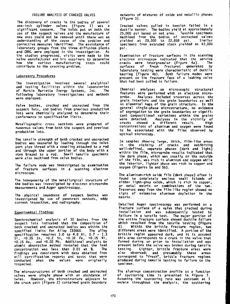
FAILURE ANALYSIS OF CRACKED VALVES
The discovery of cracks 1n the bodies of severalone-Inch cylinder valves (Figure 1) was asignificant concern. The holds put on both theuse of the suspect valves and the manufacture ofnew ones could not be removed until there was anunderstanding of the cause of the problem andcorrective measures identified. The assistance oflaboratory groups from the three diffusion plantsand ORNL were employed in the Investigation. Asthe studies progressed, visits were made to thevalve manufacturer and his suppliers to determinehow the various manufacturing steps couldcontribute to the cracking problem.
Laboratory Procedures
The Investigation involved several analyticaland testing facilities within the laboratoriesof Martin Marietta Energy Systems, Inc. Thefollowing laboratory investigations and methodswere employed.
Valve bodies, cracked and uncracked from thesuspect lots, and bodies from previous productionlots were chemically analyzed to determine theirconformance to specification limits.
Metallographic cross sections were prepared ofnumerous valves from both the suspect and previousproduction lots.
The tensile strength of both cracked and uncrackedbodies was measured by loading through the inletport pipe thread with a coupling attached to a rodand through the upper portion of the body with astem brazed to a rod. Small tensile specimenswere also machined from valve bodies.
The failure mode was Investigated by examinationof fracture surfaces In a scanning electronmicroscope.
The homogeneity of the metallurgical structure ofthe bodies was Investigated by electron microprobemeasurements and Auger spectroscopy.
The physical soundness of suspect bodies wasInvestigated by use of penetrant methods, eddycurrent Inspection, and radiography.
Experimental Findings
Spectrochemical analysis of 30 bodies from thesuspect lots Indicated that the composition ofboth cracked and uncracked bodies was within thespecified limits for Alloy C63600. The alloyspecification requires 3.0 to 4.0 Al, 0.7 - 1.3Si, <0.35 Zn, <0.2 Sn, <0.10 Fe, <0.15 N1,<0.15 As, and <0.03 Pb. Additional analysis byatomic absorption method revealed that the leadconcentration was less than 0.01 wt %. Thefindings are consistent with data obtained frommill certification reports and tests that wereconducted when the values were originallyinspected.
The microstructures of both cracked and uncrackedvalves were single phase with an abundance oftwins. However, the microstructure adjacent tothe crack path (Figure 2) contained grain boundary
networks of mixtures of oxide and metallic phases(Figure 3).
Cracked valves pulled in tension failed in aductile manner. The bodies yield at approximately25,000 psi based on net area. Tensile specimensmachined from the bodies of uncracked valvesyielded at 20,000 to 22,000 psi. Similarspecimens from extruded stock yielded at 43,000ps1.
Examination of fracture surfaces in the scanningelectron microscope Indicated that the servicecracks were intergranular (Figure 4a). Thesurfaces of fresh fractures generated bylaboratory testing were characteristic of ductiletearing (Figure 4b). Both failure modes werepresent on the fracture face of a leaking valvethat had been pulled to failure.
Chemical analyses on microscopic structuralfeatures were performed with an electron micro-probe. Analyses included traverses across thegrain Interiors and the grain boundaries as wellas elemental maps of the grain structure. In thegeneral single-phase microstructure, no evidenceof segregation to the grain boundaries or signifi-cant compositional variations within the grainswere detected. Analyses In the vicinity ofcracks showed a different result. Highconcentrations of aluminum and oxygen were foundto be associated with the films observed byoptical microscopy.
In samples showing large, thick, film-like areasin the vicinity of cracks and exhibitingwell-defined, separate phases (dark and light)within the film, microprobe results Indicated thatthe dark phase, which was usually on the outsideof the film, was rich in aluminum and oxygen whilethe Interior, lighter phase was rich in copper andoxygen (Figures 5a and 5b).
The aluminum-rich oxide film (dark phase) often isfound to completely enclose small Islands ofeither light-grey oxide, which is rich 1n copper,or metal matrix or combinations of the two.Traverses away from the film-Uke region showed nosigns of extensive aluminum depletion in thematrix.
Detailed Auger spectroscopy was performed on afracture surface of a valve that cracked duringinstallation and was subsequently tested tofailure in a tensile test. The major portion ofthe entire fracture surface showed ductile failurewhich resulted from the tensile testing (Figure6). Within the brittle fracture region, twodifferent areas were identified. A portion of thebrittle region appeared dark, and it is assumedthis area corresponds to a crack in the valve thatformed during or prior to installation and waspresent before the valve was broken during tensiletesting. Lighter, brittle fracture areas werealso observed; and presumably these areascorrespond to "fresh", brittle fracture regionsproduced during tensile testing to failure to thespecimen.
The aluminum concentration profile as a functionof sputtering time is presented in Figure 7.Assuming the sputtering rate was constant at 1nm/min throughout the analysis, the sputtering
172

time is linearly related to the depth ofsputtering; and therefore a distance scale issuperimposed on the time axis. Analyses from thedark, brittle area are marked Bl and B2. A thirdarea on the dark surface that had a differentmorphology and was analyzed separately is markedB3. The results from the "fresh", brittle areaare marked B4. Results from the ductile area aremarked Dl. The ductile area (Dl) contained lessthan 10% aluminum, which is In good agreement withthe level expected 1n the matrix. The brittleareas, Bl, B2, and B4, contain quite high levelsof aluminum, 40% to 70%, Indicating significantaluminum enrichment. Finally, the area marked B3was nearly pure aluminum (>90%). The remainder ofthe metallic constituent was copper.
The failures of the one-inch cylinder valve bodiesprompted investigations to determine if non-destructive methods can be used to detect flawsin each of the material forms. Investigation byan ultrasonic method Indicated that small, <l/8inch, flaws could be detected within the forgedbody. Examination of the machined valve bodiesindicated that surface flaws could be detected bya penetrant method if the solder coating on thethreads of the inlet part was removed and thevalve surface was chemically etched to removedisturbed metal. The use of eddy current methodsfor inspection of the bore of the inlet part wasinvestigated. It was determined that the methodwould only detect through cracks or flaws thatwere within 20 mils of the bore surface.
The Metals and Ceramics Division at ORNLinvestigated the feasibility of locating flaws inthe wall of the inlet port by the use of a specialX-ray tube which procduces a 360° panoramicexposure of the bore with a single radiograph.Indications of small (£1/8 Inch) flaws wereobserved in examination of the suspect valves.The utilization of the method is limited becausethe tin solder coating must be removed beforeinspection.
CONCLUSIONS
Intergranular networks of oxides were found 1n thevicinity of the cracks in the valve bodies. Anisolated region of nearly pure aluminum was alsoidentified on a fracture surface. This Indicatedthat the original melt was probably inhomogeneous.Such nearly pure aluminum inhomogeneities couldresult in cracking during processing withsubsequent heavy oxide formation along the cracks,or these areas could promote oxide formation whichrendered the material susceptible to cracking.The inhomogeneity appeared to be localized withinsmall volume elements of a few valves. It was notdetectable by routine chemical or mechanical testsof the forging stock or finished bodies. Theunflawed portion of a cracked valve body exhibiteda ductile failure mode, and its microstructure wasfree of grain boundary films.
The Superior one-Inch angel valve designated Heats17 through 22 are not acceptable for use.Nondestructive methods are being analyzed todetermine a method in distinguishing acceptablevalves from rejectable valves.
NEW VALVE ORDERS
The manufacturing processes have been modified toimprove the reliability of new valves:
1. The alloy, C63600, is now prepared by use of amaster alloy instead of additions of purealuminum.
2. The body forgings are inspected by ultrasonicand penetrant methods.
3. The final pressure test of the assembled valveis conducted before the threads of the inletpart are coated with solder.
4. An investigation would be conducted ifforgings or valve bodies do not meetacceptance criteria.
The investigations have identified the probablecause of the failures and structural weakness thathas made the use of the suspect valves anunacceptable risk. Revisions of the manufacturingprocesses and the formation of a comprehensivequality assurance plan should insure that newvalves are free of material-related problems.
ACKNOWLEDGEMENT
The authors wish to acknowledge the contributionfrom the staff of the Metals and CeramicsDivision, Oak Ridge National Laboratory. Theresults of the analytical work by electronml croprobe and Auger methods was excerpted fromMicrostructional Evaluation of UF6 Cylinder ValveBodies, J. M. Vitek, L. Heatherly, and T. J.Henson, Report No. ORNL-6467 (in preparation).
Fig. 1. Valve Body That Cracked After Installationin a Cylinder Coupling and Mas SubsequentlyPulled to Failure in the Laboratory
173

Fig. 2. Crack Network Through the Wall of an Inlet Port
* • *
Fig. 3. Network of Grain Boundary Films Near Crack
174
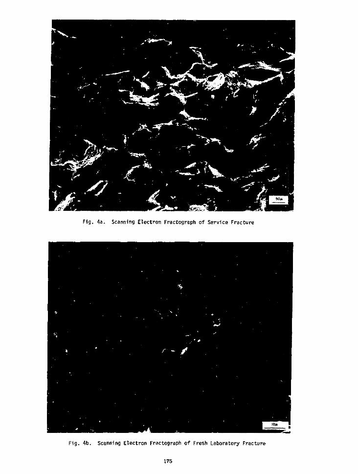
Fig. 4a. Scanning Electron Fractograph of Service Fracture
Fig. 4b. Scanning Electron Fractograph of Fresh Laboratory Fracture
175
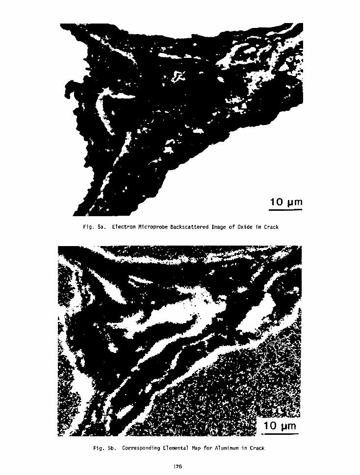
10
Fig. 5a. Electron Microprobe Backscattered Image of Oxide in Crack
Fig. 5b. Corresponding Elemental Map for Aluminum in Crack
176
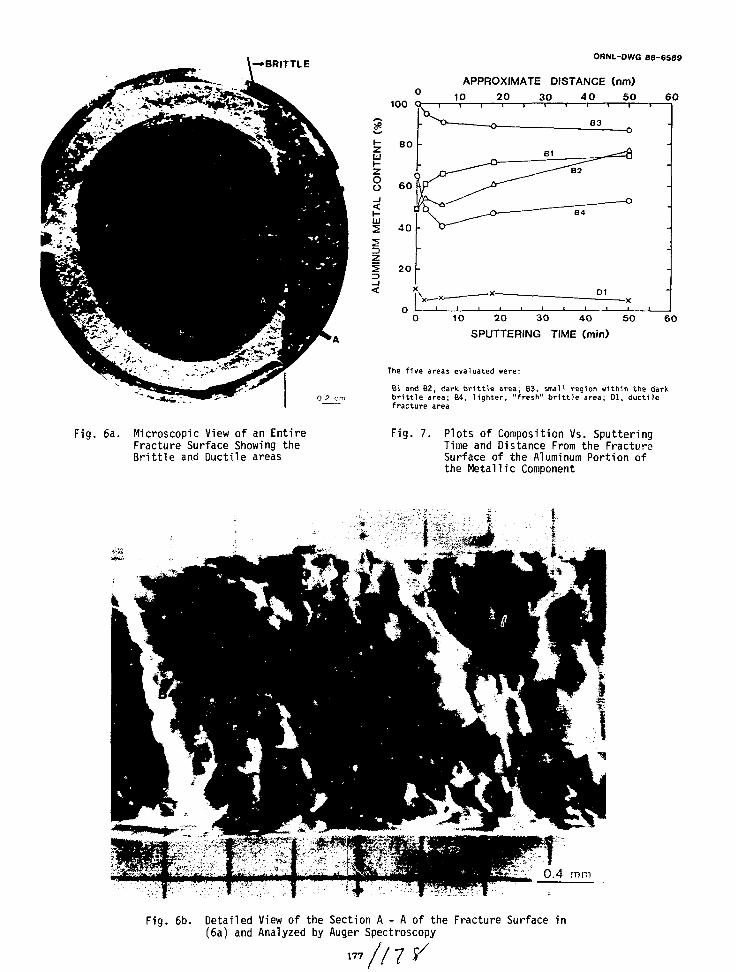
WBRITTLEORNL-DWG 88-6589
APPROXIMATE DISTANCE (nm)10 20 30 40 50
10 20 30 40 50
SPUTTERING TIME (min)6 0
Bl and B2, dark brittle area; B3, small region within the darkbrittle area; B4, lighter, "fresh" brittle area; Dl, ductilefracture area
Fig. 6a. Microscopic View of an EntireFracture Surface Showing theBrittle and Ductile areas
Fig. 7. Plots of Composition Vs. SputteringTime and Distance From the FractureSurface of the Aluminum Portion ofthe Metallic Component
Fig. 6b. Detailed View of the Section A - A of the Fracture Surface in(6a) and Analyzed by Auger Spectroscopy
177
TESTING OF UF( PIGTAILS
R. E. DomingScientist Specialist
Martin Marietta Energy Systems, Inc.Portsmouth Gaseous Diffusion Plant
Piketon, Ohio, USA
ABSTRACT
The transfer of UF, and other hazardous materialsbetween cylinders and manifolds requires the useof pigtails - flexible couplings which allow formisalignment between those parts of the transfersystem while providing the required containment ofmaterial. To ensure reliability of materials anddesigns, a UF, pigtail test facility was designedand fabricated at the Portsmouth Gaseous DiffusionPlant. This test facility is capable of accom-modating the broad ranges of variables found inactual usage. A test is performed by rotating oneend of a pressurized pigtail in a circular patternat the design flexibility requirement until adecrease in operating pressure is detected whichdenotes failure.
Testing of pigtails has been most beneficial inidentifying deficiencies in design, fabrication,and materials of construction. This paper dis-cusses the testing and results of twenty pigtaildesigns. The resultant uniform fabrication proce-dures, along with improved inspection methods,have produced safer and more reliable designs.
INTRODUCTION
The flexible coupling used in transferring aliquid or a gas between a manifold system and acylinder is known as a pigtail. A certain amountof flexibility is necessary to compensate for thenormal misalignments between the transfer systemand the cylinder. Pigtails for UF6 transfer atthe Portsmouth facility can vary in length fromabout 18 inches to several feet and areconstructed from a variety of materials (tygontubing, copper, and Monel) depending on serviceconditions which can range from a vacuum to 100psi and temperatures up to 250°F. In the late1970s a corrugated metal hose was proposed toincrease flexibility. Since this design changewas considered a dramatic deviation from theexisting, field-proven, pigtail designs, testingof the design prior to field usage was deemednecessary. A laboratory pigtail test facility wastherefore designed and constructed. After thesuccessful initial testing of the corrugated metalhose pigtail design, similar testing of theexisting pigtail designs was proposed to documenttheir fitness for intended field service.
The pigtail test facility, Figure 1, was designedto simulate the maximum flexure that the pigtailwould experience under normal operating con-ditions. This is accomplished by offsetting oneend of the pigtail to simulate actual usageflexure and then revolving this end of the pigtailthrough 360°. The rotational speed of the testeris standardized at six revolutions per minute tominimize local heat buildup. During testing thepigtails are pressurized and testing is terminatedafter a predetermined number of cycles is attainedor upon the detection of a decrease in pigtailpressure. The design parameters capable of beinginvestigated are listed in Table 1.
TABLE 1 PIGTAIL TEST FACILITY CAPABILITIES
Parameter
TemperaturePressureAngular OffsetPigtail LengthsParallel
DisplacementFlexibility
Test Capability
Ambient to 300°F (147°C)15 - 600 psia (0.1 - 4.1 MPa)0° - 90°0.5 - 8 feet (0.2 - 2.4m)
4 inches max. (10 cm)±12 inches max. (±30.5 cm)
A number of safety fixtures have been incorporatedinto the test system and include safety interlocksinstalled on the test chamber doors which inter-rupt the drive-motor power and reduce the systempressure to atmospheric when activated. Othersafety features include pressure relief valves toprevent overpressuring, system power interlocks,and an expandable metal, Lexan lined containmentchamber to protect against a catastrophic failure.
TESTING RESULTS
Pigtail designs for over twenty different applica-tions have been tested using the pigtail testfacility. Several of these designs are shown inFigure 2. The majority of these pigtails wereused for the transfer of UF6, considered as apotentially high risk operation. Three types ofdeficiencies were discovered as a result oftesting these pigtails. The deficiencies wereidentified as resulting from design, materials,and fabrication techniques.
179
Fig. 1. Pigtail Test Facility Showing Corrugated Metal HoseBeing Installed for Testing
180
Insulated 3/8" Copper Tubing UFg Sampling Pigtails
Insulated 1-1/4" Copper Tubing UF, Cylinder Transfer Pigtail
Fig. 2. Examples of UF, Pigtails That Have Been Tested
181

A design deficiency was detected in a prototypepigtail for use in the high assay sampling area(HASA). The pigtail was fabricated from corru-gated Monel hose and tested per the parameters forthat application. The testing indicated that thepigtail was too short to provide the requiredflexibility. The pigtail took a permanent setnear the rotating end fitting. This "set" couldreduce the flexibility needed to obtain satisfac-tory alignment and sealing during subsequent con-nections. After adding two inches to the lengthof the pigtail, the "set" was eliminated, andsatisfactory performance was attained.
A material problem was identified during the test-ing of a copper tubing pigtail. The indenture onthe tubing which identified the ASTM Standard ofthe tubing was too heavily stamped (Figure 3) forthe application. The stamping had reduced thewall thickness locally by 14 percent. This re-duced wall thickness and the sharp corners of theindentations acted as a notch stress riser andinitiated a metal fatigue failure as shown inFigure 4. An inspection procedure and qualityassurance actions during tubing procured forpigtail applications have been incorporated toreduce the future risk of receiving unusablematerial.
The fabrication deficiency that was detected wasdue to a poorly brazed joint. The braze profileof the tubing-to-fitting connection displayed aconcave radius, which resulted in failure at thebraze joint during testing. The lifetime of thispigtail was reduced by 75% compared to a similarpigtail design which had a properly brazed connec-tion. Quality Control inspectors were made awareof the potential problem, and the quality of thebraze joint has been made part of the inspectioncriteria.
CONCLUSION
The normal failure mode of pigtails in service isalmost always due to abuse, or thread wear due, inpart, to cross threading of the fittings. Thefittings become cross threaded during hook-up whenthe misalignment between cylinder and manifoldexceeds the design allowance or when the pigtailflexibility is reduced by work hardening or per-manent deformation. Normal pressure and vacuumtesting as part of the standard operating pro-cedures detect these field failures. Suchfailures occur at only fractions of the maximumtest lifetimes predicted by the flexure testing ofadequately designed pigtails. The pigtail testresults therefore can not be used to predict fieldusage life times, but the results have proven suc-cessful in identifying design deficiencies beforethe pigtail was put into field use. The presentuse of the pigtail test facility is to test pig-tails which have had a design change and to aid indetermining the cause of premature pigtailfailures. The success of this testing system isone additional step in assuring a more reliabletransfer of UF6 and in reducing the risks andvulnerabilities associated with those transfers.
Fig. 3. Variations in Stamping of CopperTubing for Pigtail Fabrication
Fig. 4. Crack Initiation in StampingIndentation
182

SAFE TRANSPORT OF OF-6 IN THE PRIVATE SECTOR, 1967-1988
BERT JODY, JR.
The topic of my paper, "Safe Transport of UF-6 inthe Private Sector, 1967-1988", is a description ofthe attitudes, technical applications and opera-tional requirements for UF-6 developed by ourcompany, Davis Transport in conjunction with thehelp and support of the converters, notably AlliedChemical Company and Eldorado Nuclear, Ltd., overa period of twenty years. This discourse has to dowith our own experience with UF-6 and does not pur-port to cover the entire field of nuclear trans-portation. It would seem proper to establish thehistorical background and political climate inwhich the UF-6 conversion corqpanies came intobeing, in order to understand those transportdecisions which have been made to insure safety.
It is clear that, dating back at least to theAtonic Energy Act of 1954, the general policy ofthe U. S. Government has always been to encourageand foster the development of a private nuclearindustry and to refrain from competing with suchindustry. The Private Ownership Amendment to theAct is probably the most significant reflection ofthat long standing policy. That amendment author-ized private ownership of "special nuclear materi-al" , including uranium enriched in the isotope ofU-235. In the 1960's the Act was further amendedand criteria published governing the establishmentof the Government's massive uranium enrichment pro-gram which began on January 1st, 1969. Under thisprogram, customers (mostly domestic and foreignutilities) deliver feed material (UF-6) to theGovernment's gaseous diffusion plants and subse-quently receive therefrom enriched uranium to befurther processed into fuel for use in nuclearpower plants.
It was in this environment that Davis Transportentered into discussions with Allied Chemical inlate 1967 to develop a transport system that wouldmove the first loads of UF-6 under the enrichmentprogram on January 2nd, 1969.
Safety was the subject which overshadowed everyaspect of discussions with Allied Chemical whichbegan in the fall of 1967. The transport subjectswere basically three in number—the containmentcylinder, the trailer structure which would carryit, and the training of personnel who would movethe cylinders. First, we discussed the cylinder.A pressure vessel twelve and one half feet long,four feet in diameter, with a loaded weight of32,000 lbs! This concentrated weight was designedfor in-plant applications, but posed real problemsin transportation. The cylinder could be deformed,it required a special strong back to lift it, the
cylinder lugs could not be used in the tie downarrangement for fear of damage to the cylinder,and the trailer frame must support the concentratedweight in approximately six feet of length. As ifthese problems were not enough, the cylinder con-tents were expensive, corrosive and radioactive ifexposed. The cylinders were labeled and placardedradioactive, therefore the public would be involvedduring transport. Discussions between Davis,Birmingham Manufacturing Co., our trailer con-structor, and Allied Chemical established fourareas of concern for the trailer. Frame strengthcenter of gravity, suspension and tie down assem-blies. Frame strength and its center of gravitywere considered concomitantly. The cylinder wasto be placed in the horizontal center of gravityover the trailer's main rails at the lowest possi-ble vertical center of gravity to avoid overturn.It was determined that the main frame of thetrailer must be able to sustain static weights oftwo and one half times the weight of the cylinderthroughout its length, if we were to have any hopeof longevity in operation, the trailer would be a"single drop" platform, with the single loadedcylinder immediately behind the neck transition forload balance and protection from impact. Ihissingle drop concept lowered the vertical center ofgravity from the nominal 54" deck height of a con-ventional flat bed to 40 inches of deck height.This one factor reduced the potential for overturnby 14%. The suspension had to reduce the possibil-ity of "road shock" to the cylinder. Spring sus-pensions on relatively short trailers have atendency to "crow hop" or lose effective brake timeunder emergency conditions, and they transmit agood deal of road shock to a fixed load. We,therefore, applied Neway Air bag suspensions to thetrailers. Although such suspensions are cannontoday, they were unusual in 1968. It was felt thatwith automatic leveling valves, the air suspensionwould lower potential shock to the cylinder andtrailer frame and should give better brake appli-cation. As it turned out, both suppositions wereaccurate. These first generation trailers havebeen in operation for almost twenty years without asingle frame failure or weld requirement. Interms of mileage they have each accumulated some1,700,000 miles without failure.
With the suspension issue resolved, we moved towardsolution of the tie down problem. Given the forceswhich could be exerted on the cylinder in emergencystopping conditions, it was decided that permanentcradles would be welded and bolted into the mainframe structure of the trailers. These cradles,two to each cylinder, were of massive 1/2" steel
183
plate which, when completed, allowed the bottom ofthe cylinder to sit within three inches of thetrailer deck while the ends of the cradle rose somefourteen inches up the side of the cylinder. Theload cradles were placed on the trailer in such away that the outboard stiffening rings of any ex-isting 48 inch cylinder would act to stop forwardor aft movement, should it occur. The cradles weretwelve (12") inches wide at the mating surface topreclude any "knife edge" effect on the cylinderskin and to provide a large weld and bolt area forsecuring the cradle.
The upper half of the original tie downs consistedof two 52,000 1b. test wire rope cables which wereattached to equal strength clevis and ratchetsfastened to the trailer deck thru eye assemblieswhich were in turn welded into the trailer frame.When assembled and tied down, the cylinders almostbecame a part of the trailer.
Operational tests were conducted of all the trailerfunctions at the time of start up. The resultswere exactly as programed with the exception ofbraking and "tracking" of the trailer as a towedunit. In both those cases the results were supe-rior to our expectations. The unit braked with noinclination toward "jack-knifing" and it trackedbetter than any trailer we had seen at that time.The trailer showed little attempt to "heel over" intight turns because of the low center of gravityand the automatic leveling valve of the air sus-pension.
On January 1st, 1969 these units were loaded atAllied Chemical in Metropolis, Illinois and thefirst cylinders delivered to the Oak Ridge,Tennessee and Piketon, Ohio diffusion facilities onJanuary 2nd, 1969.
The rest, as they say, would be history, exceptthat the nuclear industry was growing. In 1970 weopened discussions for another transport system inconjunction with Eldorado Nuclear, Ltd. of PortHope, Ontario. Eldorado had a need to ship 48x or10 ton cylinders, in addition to the 48y or 14 toncylinders we had been carrying. Was it possible,under existing road weight laws, to carry two 48xcylinders? Working with Birmingham Mfg. Co., wedeveloped a trailer which could do that task with-out sacrificing the strength factors developed inthe first generation trailers. Given the samesafety perimeters, we elected to use fabricatedmain beams of Tl steel. These main rails wouldhave the cradles built as an integral part of thestructure inside the rails and the trailer wouldnot have a deck. This trailer somewhat irrever-ently was dubbed "slantback" because of its 7% cantfrom front to rear. The cant, or slanted conditionof the trailer was deliberate in that it loweredthe over-all vertical center of gravity, especiallyat the rear. Because of our experience with theprevious drop decks, we knew that the tail of thetrailer, anchored by a 48x cylinder, would havemuch less inclination to move away from the centerline of travel during a turn. Therefore, thecylinders were placed on the nose of the trailerand the tail of the trailer for load balance andtracking ability. The slanted 7% steel frame per-mitted static strength in the sane range as theoriginal trailers and created a new stoppingadvantage under emergency conditions. The
cylinders' "G forces" pushed forward but down intothe frame, giving the trailer the appearance of"tucking its tail" when the brakes were applied.This factor, coupled with the now standard airsuspension, gave exceptional stability to whatWDuld otherwise appear to be an unstable structure.This type trailer was put in service during 1970and 1971 and continues in service to date. Nostructural failures have occurred in this modelduring their seventeen year history and 6,000,000cumulative miles of operation. When one realizesthat this unit has an empty weight of only 9200ibs., it is indeed a remarkable performance.
During the period of time between the second andthird generation trailers, the upper tie downunits were changed from cable to four inch nylonstraps. These nylon restraints were accepted byAllied and Eldorado after some six months ofexamination of their properties and specificassurances by the manufacturer of their strength.The strapping is certified to 20,000 lbs. persingle end strength. This strength is multipliedin that it is attached on both ends. Three (3)tie downs are used to secure the 48y or 14 toncylinder and two (2) tie downs are used for the48x or ten ton cylinder. This configurationexceeds DOT restraint requirements. The advan-tages of this tie down are numerous. First, anydamage to the tie down is immediately visable tothe driver, loading crew, consignee or regulatoryinspector, specifically fraying, cuts or bums.The strapping is impervious to damage by roadsalt which affected the cable tie downs, andbecause of its wide, flat, contact with the cylin-der, cannot scar or dent the surface. This isespecially true when light wall cylinders are tobe moved. We have found that certified nylonstraps "set" to the load and do not require con-tinuous retightening which occurred with the useof wire rope cable.
In 1980 the U. S. motor carrier industry wasfavored with deregulation, a recession andfortunately, higher weight limits. During theyears of 1980 and 1981, Phillip Smith of LiddelBirmingham Trailer Co. and I collaborated todevelop an entirely new vehicle whose purpose wasto provide multiple load capability for thenuclear industry. The resultant trailer, calledan MVT, incorporated the most positive features ofthe two previous designs and was constructed undera published Quality Assurance plan. This unit,built of Tl steel was both a drop frame and a"rail" trailer. It has a static weight capacityof better than 3 times loaded weight of 50,000lbs. and can handle many nuclear packages.
Its primary purpose is to move UF-6 cylinders.The cradles for three cylinders are built into itsframe. The main deck height is only 36 inches.The tie down attachments for the certified webbingare close to the cylinders which exerts moreholding capacity and more surface contact. Thetrailer is equipped with disappearing walk boardsfor handling crews and can be equipped with awinch driver slide which will carry the type Boverpack for the enriched 48x cylinder.
The slide can be moved forward or back dependingupon the load condition of the overpack. Thetrailer is equipped with a "plug in" third axle
184
for loads which exceed standard five axle config-urations and can be equipped to move 30b overpacksas well as five ton UF-4 hoppers.
Air suspension of all three axles coupled with lowprofile tires, allows a lower wider "foot print"for the trailer.
This unit was bom out of the never ending questfor safe, versatile, high quality equipmentnecessary to our industry.
Returning now to the original discussion withAllied and later with Eldorado, the third consid-eration was training of personnel.
The driver had to be a responsible person whoknew now to safely drive a tractor/trailer,attend to all his load related and DOT paperwork,and then what? Was it necessary to educate thedriver to the level of a health physicist? Thecollective decision was in every case "no, we didnot need an "on board1 health physicist", but wedid need a driver who knew the properties of UF-6,why it was contained in a pressure vessel, and theresponsibilities which he, the driver, assuredtoward the movement of such material on publichighways. Including the driver as a "team member"conpleted the safety loop in transport.
There is a general assumption that a truck driver,trained to operate a class eight road tractor, canthen attach it to any trailer with whatever load itmay carry, and deliver the load safely. Nothing isfurther from the truth. Each type of trailerequipment and load has peculiarities. Each typecan be dangerous if not handled properly. A drivermust have confidence in his ability to handle thephysical dynamics of the trailer which he pulls andconfidence in the load strength of the towed unit.When this condition exists, the tractor/trailerbecomes an extension of his driving skill and he,the driver, is concentrating on observing the roadconditions and traffic around him.
We have always used company drivers and companyowned tractors for nuclear transportation.Operational control is better and individualresponsibility is promoted through this control.
This paper has, in a very brief way, ej^mined theingredients of what we have come to cfj.1 anengineered transport system. The ongoing series ofdiscussions, periods of construction,testing ofequipment and the never ending training of person-nel have lcng since welded themselves into a singleentity with one purpose, the delivery of UF-6 andother nuclear materials safely, quietly and effi-ciently. At this point we have moved some750,000,000 pounds of UF-6 without accident orincident. There are no awards except the business.We premised to do a job and we have done it. Fromthis experience we have made observations and drawninevitable conclusions for safe operation.
We have observed that all three North Americanconversion companies have, from inception, used theservices of carriers with specialized, dedicated,trailer equipment and trained personnel. Thoseassociations have been long term.
We have observed that those same converters have
worked closely with their carrier to maintainequipment levels, training and a positive relation-ship with the public. We have further observedover the past nineteen years of operation that toour knowledge, not one cylinder, loaded on specialequipment at the North American conversion plantsand destined for delivery to the U. S. diffusionsystem, has ever been involved in an accident, anaccident related overturn, structural collapse,fall from a trailer, or resulted in an injury to asingle person during transport. By contrast, wehave observed cylinders consigned to the diffusionplants or ports, on systems other than specialized,which have fallen from trains or trailers, causedvans to collapse or overturn, arrive at at leastone diffusion plant stacked vertically in a van,and again, jumbled together in gondola cars withtheir dunnage destroyed. We have observed cylin-ders with inadequate tie downs and mounted on sub-standard structures which seem to have littlerelationship to the excellence of the industrywhich they purport to serve. If this comparison isstark, it is also unfortunately real.
These observations have led our conpany to certainconclusions.
The basic conclusion is that engineered motortransport systems, incorporating dedicated peopleand equipment, are the safest means to deliverUF-6 or any other truck load quantity of radio-active material.
An "engineered motor transport system" (E.M.T.) isone in which the equipment has been built tohandle the specific loads which it will carry. TheE.M.T. system incorporates the personnel of thecarrier, the equipment manufacturer, and theshipper in the final decision to submit the endproject to the road. Everyone is responsible forits success.
That conclusion is based upon the following factsabout an E.M.T. system.
An E.M.T. system is durable. Because it isdesigned to do a specific, or series of specificjobs, such a system will have the best chance forsafe operation over a long period of time. It istherefore dependable. This dependability allowsbusiness decisions to be made upon that foundation.
An. E.M.T. system is survivable. An engineeredsystem has a better chance of surviving during anyemergency condition which might exist.
An E.M.T. system is defensible. It is defensiblein law because it is durable, dependable andsurvivable. The private sector must be ever mind-ful of the possibility of legal action. E.M.T.systems adopted by the North American converters,and indeed the U. S. DOD, meet that criteriaestablished in the cannon law known as "The Act ofa Prudent Man". It is prepared to meet that furtherstatement in cannon law that, "No law or custom, nomatter how long in place, may rule to obviate theact of a prudent man".
The E.M.T. system is prudent in that every aspectof operation has been considered before submissionto the public highways.
185

Finally, the E. M.T. system, because it isdurable, dependable, survivable and defensible, isalso insurable. Insurance is one of the major con-siderations of any private sector business.Insurance markets for private sector nuclearcarriers is narrow and could become non-existent ifthe insurance industry determines that suchcarriage is not a good risk.
The E.M.T. system when used as I have defined it,can be tracked by an insurance company to assureitself that risks have been minimized throughtraining, equipment, load restraints and perhaps
most importantly, by attitude. The attitude thatsafe operation comes before any economic consider-ation will involve the insurance company as thefourth partner in the E.M.T. system in a positiveway.
I wish to thank those persons responsible for thisconference and for the opportunity to speak.
I hope that this conference will be considered as apermanent part of the nuclear information calendarin the future.
186
THE IAEA RECOMMENDATIONS FOR PROVIDING PROTECTION
DURING THE TRANSPORT OF URANIUM HEXAFLUORIDE
by I. Levin
International Atnic Energy Agency
P.O. Box 100
A 1400 Vienna
Austria
K. Wieser
Federal Institute for Material Testing
Unter den Eichen 87
D-1000 Berlin 45
F.R.G.
ABSTRACT
The Regulations for the safe transport ofradioactive materialsH), are the basis of nationaland international regulations concerning thissubject throughout the world. These regulationsrequire that subsidiary hazards associated withradioactive materials should also be considered.Other national and international regulationsconcerning the transport of dangerousmaterials('>'>4) consider that a radioactivematerial having other dangerous properties shouldbe classified as class 7.
Following this line and acting upon therecommendations of SAGSTRAM (Standing AdvisoryCommittee on the Safe Transport of RadioactiveMaterials) that the Agency should take the lead inproviding guidance to Member States with respect toUF5 packaging and transport, the Agency convenedtwo expert meetings during 1986 and 1987 in orderto look into the special problems associated withthe transport of uranium hexafluoride. The expertsidentified several areas in which additional safetymeasures should be considered if the transport ofUF5 is to have a non-radiological safety levelconsistent with that of its radiological risks.The recommendations of these groups were publishedin 198715) and together with comments received wereused by another group of experts to prepare a draftof a new safety series document.
In this presentation the new recommendations willbe described. The main safety issues to bediscussed are fire resistance, valve protection andcompatibility with service and structuralequipment. Another aspect of importance is theinterface between the process and the transportphases, bearing in mind that the same containersare used in both.
This paper will also reveal in how far the newrecommendations concerning UFg have already beenendorsed in the forthcoming European TransportRegulations (AOR/RID) together with the 1985revised Edition of IAEA Safety Series No. 6.
REFERENCES
1. Regulations for the Safe Transport ofRadioactive Material, 1985 Edition, SafetySeries No. 6, International Atomic EnergyAgency, Vienna, Austria, STI/PUB/691, 1985.
2. Recommendations on the Transport of DangerousGoods, Fourth Revised Edition, United Nations,New York, NY, USA, ST/SG/AC.10/I/Rev. 4, 1986.
3. European Agreement Concerning the InternationalCarriage of Dangerous Goods by Road (ADR) andProtocol of Signature, United Nations EconomicCommission of Europe, 1957.
4. Reglement international concernant le transportde marchandises dangereuses par chemins de ferRID, Convention relative aux transportsinternationaux ferroviares (COTIF), Officecentral des transport internationaux parchemins du fer.
5. Recommendations for Providing Protection duringthe Transport of Uranium Hexafluoride, TtCDOC423 International Atomic Energy Agency, Vienna,Austria, 1987.
187

IMPACT IN USA OF PROPOSEDIAEA RECOMMENDATIONS
M. WanglerU.S. Department of Transportation
J. W. ArendtOak Ridge Associated Universities
R. I. ReynoldsMartin Marietta Energy Systems, Inc.
Paducah Gaseous Diffusion Plant
{NOT INCLUDED IN PROCEEDINGS)
189
THE REGULATIONS AND THE PROBLEMS OFTHEIR IMPLEMENTATION IN UFB TRANSPORT
C. Devillers, M. Grenier, C. Ringot and P. WarniezCEA/IPSN, Fontenay, France
P. BlumTRANSNUCLEAIRE, France
ABSTRACT INTRODUCTION
UF6 is currently transported in packagings which were developedin the sixties — standardized and used all over the world.
In the absence of significant releases during the great number ofshipments carried out until now by all modes of transport, evenafter accidents, we must recognize that these packagings performtheir duty adequately.
Nevertheless, we must be aware that the growing amounts of UF6
issued from URT and the changes in the regulations now raises theproblem of compliance of these packagings with the latter.
Among the problems which deserve special attention, the follow-ing are particularly noteworthy:
• selection of the packaging type (Industrial, A or B type; fissileor non fissile) in terms of the origin and the enrichment of theUF6,
• design of valve covers (mechanical protection, leakage barrier,criticality control),
• assessment of material behaviour at low temperatures,
• regulatory requirements in handling, tying down cleaning andunloading,
• allowable dose rate increase in case of minor mishaps,
• behaviour in fire, taking into account the toxicity of UF6,
• identification of "special features" required in the case of"controlled moderation" of fissile packages,
• transport conditions of "empty" packagings containing "heels".(LSA or not, allowance of transport without protectivepackagings).
It seems that most of these points are purely formal and will beeasily solved by amendements to the regulations while others arespecific to the nature of UF6.
It seems also that the desirable modifications to the existingtransport packagings are relatively minor, a consensus being nec-essary on the working conditions.
The operation of the LWR reactors in service in the WesternCountries necessitates the annual transport of thousands of 48Ycylinders (each containing approximately 12.5; of natural orslightly enriched UFJ and 30B cylinders in their protectivepackaging (each containing approximately 2.25 t of low enriched
Apart from a few accidents and incidents which were minor interms of their consequences (but which focussed the attention of thepublic and the authorities on the safety problems involved in thetransport of UF6), the movement of these cylinders did not causesignificant pollution until now and therefore the nuclear industryhas not felt the need to make any changes to the routines establishedthroughout the world and laid down in ANSI-N14-1-1982 [1].
However, the recommendations concerning the transport of UF6
(TECDOC-423) [2] published in June 1987 by the IAEArecognized that this standard is not in total conformity with theIAEA-85 regulations [3] or the UNO recommendations for thetransport of dangerous goods [4], as result of changes in these twodocuments (see Table 1).
In view of the unavoidable nature of the transport of UF6 forsupplying nuclear power plants with fuel and the frequencies andtonnages involved, we felt that it was important to methodicallyidentify the differences to which [2] alludes and to propose reme-dial measures relating to the design of the packagings and theconditions of their use, and even to the regulations themselves ifdifferences are found which do not affect the safety principles onwhich they are based.
In this paper, we review the results of this analysis, which we havelimited to the case of transport using cylinders of 48 Y and 30B.
191

Table I - Key dates concerning 48Y ai»d 30B cylinders and theregulations and codes applicable to them
Year
Before1966 _1966196719681970197119721973197419751976197719781979198019811982198319841985198619871988
Commis-sioning
48Y
21 PF.l*30B
ORO
651
XXX
X
X
X
ANSI-
N14-1
X
X
X
(X)
IAEA
S.S.6
X
X
X
X
XX
UNOST/SG/AC
10-1
X(X)
* Publication of Safety Report K-1686
TYPES OF PACKAGINGS REQUIRED UNDER IAEAREGULATIONS AND UNO RECOMMENDATIONS FORTHE USUAL CONTENTS OF 48Y AND 30B CYLINDERS
As shown in Table 2, the 48Y cylinders, being normally used forthe transport of natural UF6 (LSA-1 material), might merely meetthe type IP-1 requirements if, as generally accepted, UF6 may beconsidered to be a solid. However this requires carefulconsideration as it is not the case in the transport of emptiedcylinders in which more than 80% of the product is in gaseous format the design temperature (38°C). The content is then an LSA-IImaterial and allowance must be made for the type IP-3 if it is wishedto avoid "exclusive use" constraints for the return of "empty"packagings. On the other hand, if it is accepted that all movementsof 48Y packagings are under "exclusive use" conditions, the typeIP-2 requirements suffice even for movements of slightly enrichedUF6, provided the degree of enrichment is less than 1 %, as is attimes the case for URT.
It must immediately be stated, as will be explained in detail later on,that the 48Y cylinder in all likelihood belongs to type IP-2 but notobviously to type IP-3, and that consequently the only problemwith regard to [3] relates to their transport procedures when"emptied".
Similarly, Table 2 shows that, for 30B cylinders equipped withtheir protective packagings allowance must at least be made for thetype IP-2 requirements (or type IP-3 if freedom from the "exclusiveuse" constraint is desired), in addition to those for "fissile"packagings.
It must be pointed out thai, strictly speaking, they do not need to beof type "A" or of type "B" provided they are systematically checkedand cleaned internally, as explained hereafter.
Finally, in vie w of the corrosive and toxic nature of the UF6 and thevolumes of the 48Y and 30B cylinders, they should also beapproved as "tank containers" and meet the requirements laid downfor the latter in [4].
Table 2 - Types of packagmgs required under IAEA regulationsfor the transport of industrial quantities of UF6 not morethan 5% enriched
Enrichment
of
UF6
V5% < 0.72
0.72 < U5% < 1
1 < U5% < 5
Cylinders Cylindersregularly checked liable to
and cleaned accumulateresidue
r * °f
Transport Transport low"full-
IP-1
IP-2
IP-2 fissile
"empty" volatility
IP-2 (excl. use) AIP-3 (non excl.
use)
IP-2 (excl. use) AIP-3 (non excl. :
use)
IP-2 fissile A fissile(excl. use)IP-3 fissile
(non excl. use)
PROTECTION OF THE VALVE OF 48Y CYLINDERS
The present valve cover is unnecessarily protruding, and thisshould be avoided for conformity with [3]. In addition, not only istheir correct installation difficult to check but we now know the riskof damaging the valve during makeshift handling operations forremote recovery of cylinders (wreck of the Mont Louis).
Finally, tests showed that they do not guarantee leaktightness of thevalve in the case of a full cylinder falling 0.6 m onto a rigid surfaceas provided in §§5.3.7 and 6.2.2 of [3].
A large number of solutions to these problems have been proposedand all have their advantages and disadvantages. Certain areextremely simple and inexpensive. But if it is desired for the 48Ycylinder to be considered to be of the IP-3 type and thus usable for"emptied" return transport and not necessarily in "exclusive use",it is necessary for the cover to also constitute an "enclosure capable
192

of retaining any leakage from the valve", which is not currently the
case.
For instance, the cover and its attachment to the cylinder could beof the type schematically shown in Figure 1.
Figure 1 - Example of installation of a leaktight valve cover on a30B cylinder
In this example, the cover is provided with a flange equipped witha gasket (preferably double) tightened by screws to a backflangewelded to the body of the cylinder.
Such a modification of the existing cylinders could be carried outon the occasion of their periodic inspection by the authorizedinspector as it is compatible, without post-weld heat treatment(PWHT), with the requirements of ASME-Section VIII [5].
This would compensate for the unsophisticated nature of the valve(which is much appreciated), or incorrect use of it, by constitutinga reliable and easily verifiable barrier capable of containing anyleakage at the valve and providing the valve with effective protec-tion against impact.
PROTECTION OF 30B CYLINDER VALVES
A distinction must be drawn between the case of "full" and"emptied" cylinders: "emptied" cylinders, which can contain asmuch as 11.35 kg of 5% enriched UF6, can be transported withoutprotective packaging, as provided under §§8.1 and 8.2 of [1].
Nevertheless, it is clear that the valve cover is not designed tocontain any leaks from the valve and, in addition, that its ability toprotect the valve in the event of a 1.2 m drop onto a hard surface or
the impact of a 6 kg bar falling from a height of 1 m remains to bedemonstrated in the case of a bare 30B cylinder.
It is for this reason that a cover of the type already proposed for the48 Y cylinders would be desirable to enable the cylinder to meet theregulatory requirements applicable to IP-2 and IP-3 packagings.
The 30B cylinders containing more than 11.35 kg of UF6 must betransported inside a protective packaging such as the 21 PF.l type.This assembly constitutes a "fissile" package of which the nuclearsafety and the approval are based on the "controlled moderation"principle.
Indeed, the authorized content of the package is limited to 2,279 kgof 5% enriched UFS, whereas the minimum volume of a 30Bcylinder is 736 litres.
As the density of UFS is close to 5.1 g/cc at 20°C, within a 30Bcylinder containing the maximum authorized load there willremain a void (plenum) of which the volume at 20°C will be at least:
736-2279
= 289 litres
Should water enter this plenum, it will react with the UF6 in thefollowing manner:
UF4 + 2H2O -> UO2F2 + 4FH
At 20°C, UO2F2 and FH are respectively a solid and a liquid, bothbeing soluble in water.
Consequently, if a 30B cylinder with a leak is immersed in waterat a depth of 15 m as provided in [3], its internal moderation is onlylimiied by the quantity of hydrogen in the water liable to occupy thevolume of the plenum, i.e.
289 x - j | = 32 kg
This is considerably more than it is necessary to attain the criticalstate, which for a homogeneous solution of a salt of 5% enricheduranium corresponds to masses of uranium and hydrogen respec-tively close to 45 kg and 4.8 kg.
For such a "fissile" package of which the nuclear safety is notguaranteed in the event of ingress of water (or loss of the content),§5.6.5 of [3] also imposes, in addition to general requirements ap-plicable in the design and utilization of all "fissile" packages,"special features" identified and recognized by the competentauthority responsible for approving the concept as preventing anyleakage, even resulting from human error. [3] also reauires thatthese "special features" be specified in the approval certificate,clearly to draw the attention of the other competent authorities tothis particularity, subject to validation.
As [3] notably considers that "multiple high standard water barri-ers" together with reliable leak tests permit compliance with this"special features" requirement, the present packaging (30B cylin-der + 21PF. 1 protective packaging) could be equipped for instancewith a valve cover of the type shown in Figure 1.
193
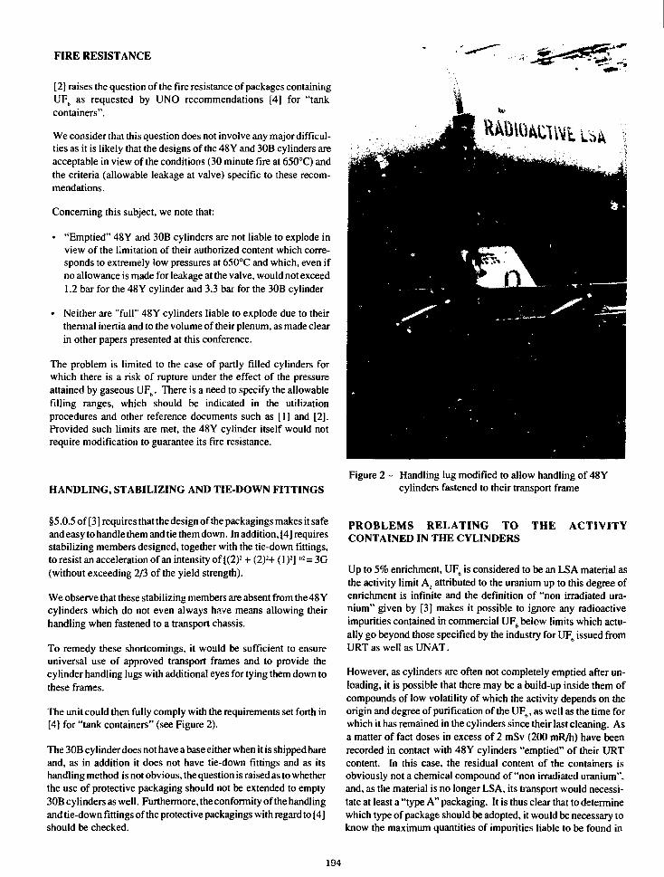
FIRE RESISTANCE
[2] raises the question of the fire resistance of packages containingUF6 as requested by UNO recommendations [4] for "tankcontainers".
We consider that this question does not involve any major difficul-ties as it is likely that the designs of the 48 Y and 30B cylinders areacceptable in view of the conditions (30 minute fire at 650°C) andthe criteria (allowable leakage at valve) specific to these recom-mendations.
Concerning this subject, we note that:
• "Emptied" 48Y and 30B cylinders are not liable to explode inview of the limitation of their authorized content which corre-sponds to extremely low pressures at 650°C and which, even ifno allowance is made for leakage at the valve, would not exceed1.2 bar for the 48Y cylinder and 3.3 bar for the 30B cylinder
• Neither are "full" 48Y cylinders liable to explode due to theirthermal inertia and to the volume of their plenum, as made clearin other papers presented at this conference.
The problem is limited to the case of partly filled cylinders forwhich there is a risk of rupture under the effect of the pressureattained by gaseous UF6. There is a need to specify the allowablefilling ranges, which should be indicated in the utilizationprocedures and other reference documents such as [1] and [2].Provided such limits are met, the 48Y cylinder itself would notrequire modification to guarantee its fire resistance.
HANDLING, STABILIZING AND TIE-DOWN FITTINGSFigure 2 - Handling lug modified to allow handling of 48Y
cylinders fastened to their transport frame
§5.0.5 of [3] requires that the design of the packagings makes it safeand easy to handle them and tie them down. In addition, [4] requiresstabilizing members designed, together with the tie-down fittings,to resist an acceleration of an intensity of [(2)2 + (2)2+ (1 )2] m = 3G(without exceeding 2/3 of the yield strength).
We observe that these stabilizing members are absent from the 48 Ycylinders which do not even always have means allowing theirhandling when fastened to a transport chassis.
To remedy these shortcomings, it would be sufficient to ensureuniversal use of approved transport frames and to provide thecylinder handling lugs with additional eyes for tying them down tothese frames.
The unit could then fully comply with the requirements set forth in[4] for "tank containers" (see Figure 2).
The 30B cylinder does not have a base either when it is shipped bareand, as in addition it does not have tie-down fittings and as itshandling method is not obvious, the question is raised as to whetherthe use of protective packaging should not be extended to empty30B cylinders as well. Furthermore, the conformity of the handlingand tie-down fittings of the protective packagings with regard to [4]should be checked.
PROBLEMS RELATING TO THE ACTIVITYCONTAINED IN THE CYLINDERS
Up to 5% enrichment, UF6 is considered to be an LSA material asthe activity limit A2 attributed to the uranium up to this degree ofenrichment is infinite and the definition of "non irradiated ura-nium" given by [3] makes it possible to ignore any radioactiveimpurities contained in commercial UF6 below limits which actu-ally go beyond those specified by the industry forUF6 issued fromURTaswellasUNAT.
However, as cylinders are often not completely emptied after un-loading, it is possible that there may be a build-up inside them ofcompounds of low volatility of which the activity depends on theorigin and degree of purification of the UF0, as well as the time forwhich it has remained in the cylinders since their last cleaning. Asa matter of fact doses in excess of 2 mSv (200 mR/h) have beenrecorded in contact with 48Y cylinders "emptied" of their URTcontent. In this case, the residual content of the containers isobviously not a chemical compound of "non irradiated uranium",and, as the material is no longer LSA, its transport would necessi-tate at least a "type A" packaging. It is thus clear that to determinewhich type of package should be adopted, it would be necessary toknow the maximum quantities of impurities liable to be found in
194
"emptied" cylinders. In reality, if we assume that the cylindersalready satisfy the requirement concerning IP-3 packagings, theymay be considered to be "type A" if the materials of which they aremade perform their functions at -40°C, the only requirementswhich practically differentiates these two types of packagings. Asconcerns the 48Y and 30B cylinders, we can consider that this re-quirement is met as they are made of ferritic steel sheet of which thethickness (<5/8 of an inch), the grade (SA516 grade 55, 60 or 65),the steel making practice (fine grain practice) and the heat treat-ment (normalized) guarantee an ample margin of safety with regardto the risk of brittle fracture, if reference is made to §5.2.3 of rec-ommendations NUREG/CR 1815 [6].
As mentioned earlier, the low volatile impurities in the UF6 accu-mulating on the inside surfaces of "emptied" cylinders create aradiological problem which can only be solved by imposingfrequent dose rate checks and thorough cleaning, as a function ofcriteria which remain to be determined. The last consequence ofthese radioactive deposits results from the requirement in [3] of notrisking an increase of more than 20% of the dose rate in contact with"type A" (or IP-3) packages after tests representative of normaltransport conditions (free fall of limited height, compression andbar penetration). If we accept the presence of radioactive depositson the inner wall of 30B cylinders, it would be necessary totransport them in a far more rigid protective packaging than the type21 PF.l if chis requirement is to be met. Cleaning of the cylinderscannot suffice to solve this somewhat formal problem, which in ouropinion cails for revision of [3].
RECOMMENDATIONS
In view of the large number of cylinders in existence, it would bedesirable for the 48Y and 30B packagings, on which the safety ofindustrial transport of UF6 depends, to remain operational for a longtime to come.
Nevertheless, this requires changes in the design of these packag-ings and the conditions of their use, which were established beforethe current regulations evolved.
Provided our interpretation of requirements of [4] concerning fireresistance is correct, these changes should presumably be minimalas concerns the packagings themselves. The principal problemrelates, in our opinion, to the valve protection covers, which shouldhave greater resistance to impact and constitute a verifiable leakagebarriers.
As concerns the operational procedures which require modifica-tion, we consider the most important to be more stringent monitor-ing of leaktightness (particularly for 30B cylinders), filling limitsfor "full" 48Y cylinders, the compulsory use of a transport frameof an approved model for these cylinders and the flushing of theinterior of cylinders which during transport have or are liable tohave a dose rate in contact or at a distance which exceeds theregulatory limits.
Finally, further to this exercise in analysis concerning the confor-mity of the 48Y and 30B cylinders with the regulations, it would bedesirable to recommend to the IAEA to reexamine their recom-mendations as specifically concerns:
• certains definitions (non-compressed gas and non-irradiateduranium),
• the conditions to be fulfilled to satisfy the controlled moderationprinciple,
• the requirements concerning handling and tying down (is theabsence of specific attachments acceptable?),
• the 20% increase of the dose rate in contact with packages after"type A" tests.
In view of the importance and urgency of these modifications to theregulations and of their possible effect on the transport of otherradioactive materials, it would no doubt be better to apply specificpackaging rules to UF6. These should, insofar as possible, beintended to perpetuate the use of the 48Y and 30B packagingswithout making concessions with regard to safety principles (risksof release, controlled moderation, handling and tying down) asgenerally applicable to the transport of dangerous goods and, morespecifically, radioactive and corrosive materials.
[1]
REFERENCES
American National Standard for Packaging of Uraniumhexafluoride for transport, ANSI N14.1,1982.
[2] Recommendations for Providing Protection during the trans-port of Uranium Hexafluoride, IAEA, TECDOC-423(1987).
[3] Regulations for the safe transport of Radioactive Material,1985 edition revised in 1986, IAEA, SS No. 6 (1985) andIAEA SS No. 6, Suppl. 1986 (1987).
[4] Transport of dangerous goods. Recommendations of theCommittee of Experts on the Transport of Dangerous Goods,ST/SG/AC.10/1 Fifth revised edition (1988).
[5] ASME Boiler and Pressure vessel code, Section VIII, Div. 1,1986 edition.
[6] Recommendations for Protecting Against Failure by BrittleFracture in Ferritic Steel Shipping Containers Up to FourInches Thick, NUREG/CR-1815 (1981).
195
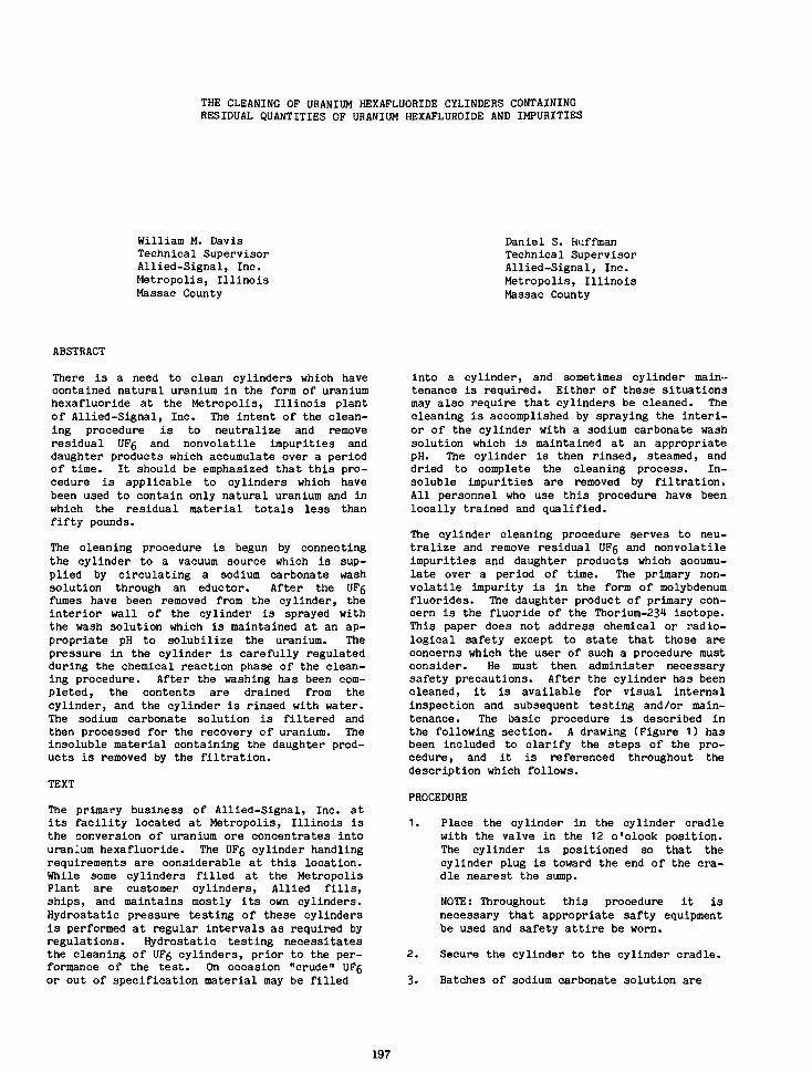
THE CLEANING OF URANIUM HEXAFLUORIDE CYLINDERS CONTAININGRESIDUAL QUANTITIES OF URANIUM HEXAFLUROIDE AND IMPURITIES
William M. DavisTechnical SupervisorAllied-Signal, Inc.Metropolis, IllinoisMassac County
Daniel S. HuffmanTechnical SupervisorAllied-Signal, Inc.Metropolis, IllinoisMassac County
ABSTRACT
There is a need to clean cylinders which havecontained natural uranium in the form of uraniumhexafluorlde at the Metropolis, Illinois plantof Allied-Signal, Inc. The intent of the clean-ing procedure is to neutralize and removeresidual UF6 and nonvolatile impurities anddaughter products which accumulate over a periodof time. It should be emphasized that this pro-cedure is applicable to cylinders which havebeen used to contain only natural uranium and inwhich the residual material totals less thanfifty pounds.
The cleaning procedure is begun by connectingthe cylinder to a vacuum source which is sup-plied by circulating a sodium carbonate washsolution through an eductor. After the UFgfumes have been removed from the cylinder, theinterior wall of the cylinder is sprayed withthe wash solution which is maintained at an ap-propriate pH to solubilize the uranium. Thepressure in the cylinder is carefully regulatedduring the chemical reaction phase of the clean-ing procedure. After the washing has been com-pleted, the contents are drained from thecylinder, and the cylinder is rinsed with water.The sodium carbonate solution is filtered andthen processed for the recovery of uranium. Theinsoluble material containing the daughter prod-ucts is removed by the filtration.
TEXT
The primary business of Allied-Signal, Inc. atits facility located at Metropolis, Illinois isthe conversion of uranium ore concentrates intouranium hexafluoride. The UFg cylinder handlingrequirements are considerable at this location-While some cylinders filled at the MetropolisPlant are customer cylinders, Allied fills,ships, and maintains mostly its own cylinders.Hydrostatic pressure testing of these cylindersis performed at regular intervals as required byregulations. Hydrostatic testing necessitatesthe cleaning of UFg cylinders, prior to the per-formance of the test. On occasion "crude" UF6or out of specification material may be filled
into a cylinder, and sometimes cylinder main-tenance is required. Either of these situationsmay also require that cylinders be cleaned. Thecleaning is accomplished by spraying the interi-or of the cylinder with a sodium carbonate washsolution which is maintained at an appropriatepH. The cylinder is then rinsed, steamed, anddried to complete the cleaning process. In-soluble impurities are removed by filtration.All personnel who use this procedure have beenlocally trained and qualified.
The cylinder cleaning procedure serves to neu-tralize and remove residual UF6 and nonvolatileimpurities and daughter products which accumu-late over a period of time. The primary non-volatile impurity is in the form of molybdenumfluorides. The daughter product of primary con-cern is the fluoride of the Thorium-234 isotope.This paper does not address chemical or radio-logical safety except to state that those areconcerns which the user of such a procedure mustconsider. He must then administer necessarysafety precautions. After the cylinder has beencleaned, it is available for visual internalinspection and subsequent testing and/or main-tenance. The basic procedure is described inthe following section. A drawing (Figure 1) hasbeen included to clarify the steps of the pro-cedure, and it is referenced throughout thedescription which follows.
PROCEDURE
1. Place the cylinder in the cylinder cradlewith the valve in the 12 o'clock position.The cylinder is positioned so that thecylinder plug is toward the end of the cra-dle nearest the sump.
NOTE: Throughout this procedure it isnecessary that appropriate safty equipmentbe used and safety attire be worn.
2. Secure the cylinder to the cylinder cradle.
3. Batches of sodium carbonate solution are
197
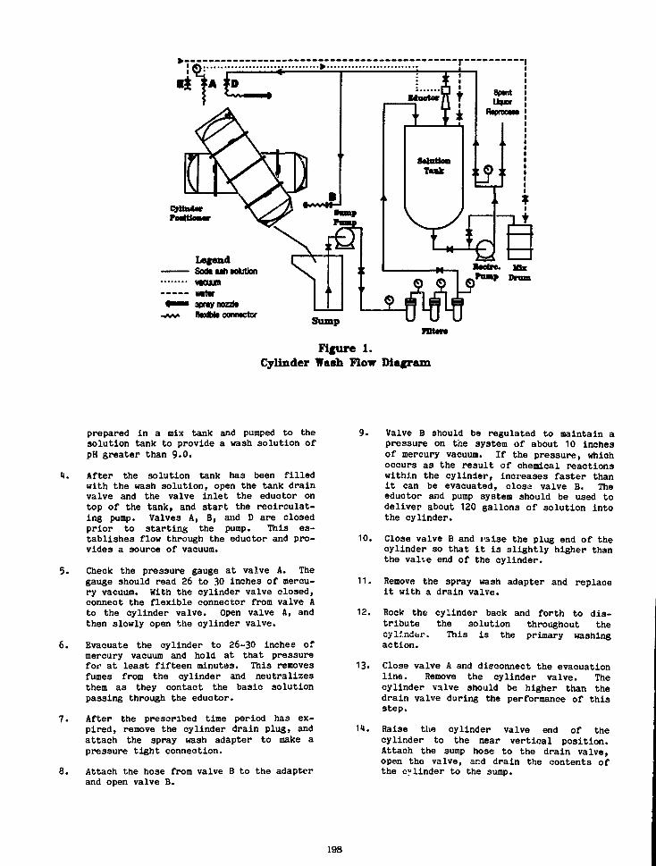
LegendSoot u h wXutlonn o u nwitvapray mateftodbto contactor
Sumpraun
Figure 1.Cylinder Wash Flow Diagram
prepared in a mix tank and pumped to thesolution tank to provide a wash solution ofpH greater* than 9.0.
4. After the solution tank has been filledwith the wash solution, open the tank drainvalve and the valve inlet the eductor ontop of the tank, and start the recirculat-ing pump. Valves A, B, and D are closedprior to starting the pump. This es-tablishes flow through the eductor and pro-vides a source of vacuum.
5. Check the pressure gauge at valve A. Thegauge should read 26 to 30 inches of mercu-ry vacuum. With the cylinder valve closed,connect the flexible connector from valve Ato the cylinder valve. Open valve A, andthen slowly open the cylinder valve.
6. Evacuate the cylinder to 26-30 inches ofmercury vacuum and hold at that pressurefor at least fifteen minutes. This removesfumes from the cylinder and neutralizesthem as they contact the basic solutionpassing through the eductor.
7. After the prescribed time period has ex-pired, remove the cylinder drain plug, andattach the spray wash adapter to make apressure tight connection.
8. Attach the hose from valve B to the adapterand open valve B.
10.
Valve B should be regulated to maintain apressure on the system of about 10 inchesof mercury vacuum. If the pressure, whichoccurs as the result of chemical reactionswithin the cylinder, increases faster thanit can be evacuated, close valve B. Theeductor and pump system should be used todeliver about 120 gallons of solution intothe cylinder.
Close valve B and raise the plug end of thecylinder so that it is slightly higher thanthe valve end of the cylinder.
11. Remove the spray wash adapter and replaceit with a drain valve.
12. Rock the cylinder back and forth to dis-tribute the solution throughout thecylinder-. This is the primary washingaction.
13. Close valve A and disconnect the evacuationline. Remove the cylinder valve. Thecylinder valve should be higher than thedrain valve during the performance of thisstep.
11. Raise the cylinder valve end of thecylinder to the near vertical position.Attach the sump hose to the drain valve,open the valve, and drain the contents ofthe cylinder to the sump.
198
15. Start the sump pump. Check the pH of thewash solution in the solution tank andmaintain it above pH = 8.C, adding addi-tional sodium carbonate if necessary.
16. Check the pressure drop across the bag fil-ters. When they become blocked, they mustbe replaced. (Filter bag replacement anddisposal are addressed in a separateprocedure)•
17. Place the spray nozzle in the cylindervalve opening. Attach the rubber hose fromvalve D to the spray nozzle, and open valveD. This is the secondary washing action.
18. Close valve D, and rinse the cylinder withwater supplied at valve E. Continue therinse until the solution draining from thecylinder is clean.
19. Close valve E, and steam through thecylinder until the walls are hot. Dry thecylinder immediately by purging dry airthrough the cylinder.
20. Visually inspect the inside of the cylinderfrom both ends. If the cylinder is notclean, the procedure must be repeated.
21. Shut down the recirculating pump. When thesump is empty, shut down the sump pump.
22. The material in the solution tank is pumpedto a uranium recovery process as required.
Future activities involving the cylinder willdepend upon whether it is to be hydrostaticallytested, repaired, or returned to service.
DISCLAIMER NOTICE
All statements, information and data givenherein are believed to be accurate and reliablebut are resented without guaranty, warranty, orresponsibility of any kind, express or implied,including, but not limited to, anyrepresentation or warranty that use of suchinformation or data is free of patentinfringement. The user should not assume thatall safety measures are indicated, or that othermeasures may not be required.
199
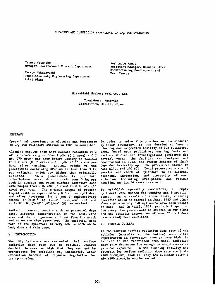
CLEANING AND INSPECTION EXPERIENCE OF UF6 30B CYLINDERS
Tsuneo WatanabeManager, Environment Control Department
Tetsuo NakabayashiSuperintendent, Engineering DepartmentTokai Plant
Yoshinobu KamelAssistant Manager, Chemical AreaManufacturing Development andTest Center
Mitsubishi Nuclear Fuel Co., Ltd.
Tokai-Mura, Naka-GunIbaraki-Ken, 319-11, Japan
ABSTRACT
Operational experience on cleaning and inspectionof UF6 30B cylinders started in 1985 is described.
Cleaning results show that surface radiation rateof cylinders ranging from 1 pSv (0.1 mrem) - 0.7mSv (70 mrem) per hour before washing Is reducedto 0.2 ftSv (0.02 mrera) - 1.5 /iSv (0.15 mrem) perhour after washing. Average weight of wetprecipitate containing uranium is less than 3 kgper cylinder, which are higher than originallyexpected. This precipitate Is put intopolyethylene packs, which contain some 3 kg perpack in average and whose surface radiation doserate ranges from 0.07 mSv (7 mrem) to 0.85 mSv (85mrem) per hour. The average amount of processliquid waste is approximately 0.6 m3 per cylinder,and after treatment its a and f) radioactivitybecome <7.4xlO"3 Bq (2xlO~7 pCi)/cm3 (a) and^.lxlO"1 Bq (3xl0~6 /uCi)/cm3 (/g) respectively.
Radiation control results such as personnel doserate, airborne concentration in the restrictedarea and that of gaseous effluent from the stackand so on are also presented. The radiation doserate of the operators is very low in both wholebody dose and skin dose.
1. INTRODUCTION
When UF6 cylinders are evacuated, their surfaceradiation dose rate due to residual uraniundaughter becomes so high that they can not betransported for refilling UF6 immediately afterevacuation because of Japanese Regulation fortransportation.
In order to solve this problem and to minimizecylinder inventory, it was decided to have acleaning and inspection facility of 30B cylinders.Then, based upon preliminary washing tests andvarious studies and Investigations performed forseveral years, the facility was designed andconstructed in 1983, the system concept of whichdepended basically upon the procedures stated inANSI N14.1 and ORO-651. Total process consists ofreceipt and check of cylinders to be cleaned,cleaning, inspection, and processing of washsolution including precipitate and residuehandling and liquid waste treatment.
To establish operating conditions, 10 emptycylinders were washed for washing and inspectiontests. As a result of these tests, cleaningoperation could be started in June, 1985 and sincethen approximately 340 cylinders have been washedto date. And in April, 1987, periodic inspectiondue every five years could be started in our plantand the periodic inspection of some 70 cylindershave already been completed.
2. PROCESS OUTLINE
As the maximum surface radiation dose rate of thecylinder (normally at the bottom) soon aftervaporization in conversion area is very high, itis left in the restricted area until radiationdose rate decreases low enough to avoid excessivepersonal exposure. In the cleaning facility thecriteria for surface radiation dose rate are 1 mSv(100 mrem)/hr, that is, only the cylinder below 1mSv (100 mrenO/hr can be washed.
201

In Fig. 1, Total Process is shown, that is, fromreceipt of cylinders to shipping of the washed andinspected cylinders.
Receipt and Check Flow Chart is shown in Fig. 2,in which check items for the cylinder to be washedare described. The most important items are theradiation dose rate and the cylinder weight, whichare compared to those of the cylinder afterwashing. Actual heel can be obtained as thedifference between the weight of the cylinderbefore washing and that after washing.
Fig. 3 shows Cleaning Flow Chart and in Fig. 4Shower Mashing seen in Fig. 3 is schematicallydescribed. Uranium concentration of the 2nd washsolution is measured and in case it exceeds 500ppmU, both shower washing and 2nd water washingare applied again. When installing a valve, avalve thread engagement of 7 minimum and 12maximum is applied by using 3 minimum of 2770kg»cm (200 foot-pounds) and a maximum of 5540kg»cm (40C foot-pounds) of wrench torque asdescribed in ANSI N14.1.
In Fig. 5 Treatment of Wash Solution consisting ofprecipitate and residue handling and liquid wastetreatment is shown.
Fig. 6 shows Inspection Flow Chart, which includesRoutine Inspection and Periodic Inspection.Periodic Inspection is observed and approved by aQualified Inspector specified in ANSI N14.1. Todate none of the cylinders inspected, which amountto some 70, have been rejected.
3. RESULTS OF OPERATION
3.1 Cleaning results
More than 340 cylinders have been washed since thecleaning operation was started. In Table 1 actualwashing data are listed and as shown in the Tabledesign capacity of one cylinder per day has beenachieved.
Average heel weight is approximately 380 g percylinder, though range of the weights is ratherwide.
Surface radiation rate of cylinders before washingranging from 1 /JSV (0.1 mrem)/hr to 0.7 mSv (70mrem)/hr becomes 0.2 pSv (0.02 mrem)/hr - 1.5 fiSv(0.15 mrem)/hr after washing.
Average weight of precipitate is about 2.6 kg percylinder, which are much higher than expectedvalue originally designed. It is necessary for usto make an effort to reduce this value. Thisprecipitate is put into polyethylene packs, whichcontain 2.9 kg per pack in average and whosesurface radiation dose rate ranges from 70 /iSv (7mrem) to 0.85 mSv (85 rarem)/hr.The average amount of process liquid waste isapproximately 0.6 m3 per cylinder and aftertreatment its a and fi radioactivity becomes6.7xl0"3 Bq (1.8xlO"7 /iCi)/cm3 (a) and 8.9xKT2 Bq(2.4xlO"6 pCi)/cm3 ($), respectively.
3.2 Radiation control
In designing the cleaning facility, much attentionwas paid to reduce operators' personnel dose ratefrom cylinder heel adopting various means such asradiation shield and automated precipitatehandling. And our experience for three yearsshows that the results of personnel dose rate ismuch lower than expected and rather comparable tothat of UF6 conversion area which gives low doserate. Actual results of dose rate are shown inTable 2.
As for environmental radioactivity, the airborneconcentration ivi the restricted area is below 5%MPC and that of gaseous effluent from the stack isbelow 0.33% MPC. Concerning the radiation doserate in the restricted area, it is 0.5 *iSv (0.05mrenO/hr around the roll stands and BG level inthe other spots.
The radiation dose rate of the operators is ND(Not Detectable) in both whole body dose and skindose. At present personnel dose rate is measuredevery three months as other areas, though in thebeginning of operation it was measured every monthto have data of dose rate.
4. CONCLUSION
The cleaning and inspection facility has beenoperated for three years without major problem anda lot of technical data have been obtained.However, there still remain some technicalproblems to be improved and those to be studied asa matter of future, which are stated below.
• Improvement of waste treatment to increaseover-all cleaning capacity
• Increase of inspection capacity• Uranium recovery from the precipitate• Study of handling and treatment of waste
from heels contaminated by ReprocessedUranium, which are expected to be handledin near future.
202

Empty Cylinder
Receipt
Storage
Washing
IInspection
Storage
Shipping
IWashed 4 Inspected
Cylinder
Wash Solution
IResidue Recovery [—«• Residue
Liquid Waste
Liquid WasteTreatment
Storage
1Liquid Effluent Pond
Fig. 1 Total Process
Empty Cylinder
Cylinder No, Heel, etc
Confirmation
Radiation Dose Rate
Measurement
Visual Inspection
Weighing
by attached cylinder recycling report
•Cylinder No•Enrichment of UF6•Tare weight(A) (from transfer report)•Internal pressure•Weight(B) (weight after evacuation)•Heel(C) (C = B-A)
Using GM survey meter6 points for shell2 points for head (valve end)4 points for head (Plug end)Criteria <1 mSv (100 mrem)/hr
External
Using weight meterScale precision : ±100
Storage
Fig. 2 Receipt and Check Flow Chart
203

Receipt Cylinder
PressureConfirmation
_L1st WaterWashing
ShowerWashing
2nd WaterWashing
2500 ppmll
<500 ppmU
ShowerWashing
SteamWashing
ShowerWashing
JLDrying
\VisualInspection
Radiation Dose RateMeasurement
ValveInstallation
Cleaned Cylinder
Using pressure gauge
- Water (19i)wash solutionValve removal
• Water (16t)
Wash Water
Water (190
wash solutionsampling & analizing of washsolution in the Laboratory
• Water (16a)
Wash Water
Steam
Drain
Water (16JI)
Wash Water
Filtered, dried & heated airExhaust Exiting dew point s-35°C
Using light sourceInternal
Using GM survey meter6 points for shell2 points for head (valve end)4 points for head (Plug end)
Using torque wrench & socketCriteria
Thread engagementmin. 7max. 12
Torquemax. 5540 kg-;mmin. 2770 kg-cm
Fig. 3 Cleaning Flow Chart
204

Nozzle
Water Supply,, . ., Pressurized Spray HaterWash Water Drain (about 2 kg/cm?)
Fig- 4 Shower Washing
Wash Solution
Precipitate
Packing &Sealing
hU Precipitation
— Na(»
ICentrifugal Separation
(a, F)Precipitation
Filtration
•
—A
f Ca(0H)2
\ NaOHL FeCls
Residue
ContainmentPoly Pack
Storage
Filtrate
(B)Ion Exchange
ContaiDrum
nment
Storage
Discharge to the pond
Fig. 5 Treatment of Wash Siolution
205

Cleaned Cylinder
Visual Inspection
Routine Periodic
Wall Thickness
Measurement
Hydrostatic
Pressure Test
Drying
Valve
Installation
Air Leak
Test
Evacuation
Weighing
External, Internal
Using ultrasonic thickness meter
12 points for shel14 points for each head
Criteria s8 mm
Water
Test pressure: 28.2 kg/cm2G
AirFiltered, dried and heated air
Using torque wrench & socketCriteria
Thread engagementmin. 7max. 12
Torquemax. 5540 kg-cmmin. 2770 kg-cm
AirFiltered and dried air 7.1 kg/cm2GApply Carbona soapless lather
• AirUsing Vacuum pumpVacuum <-690 mmHg
Using weight meterScale precision : ±100 g
Accepted Cylinder
Fig. 6 Inspection Flow Chart
206
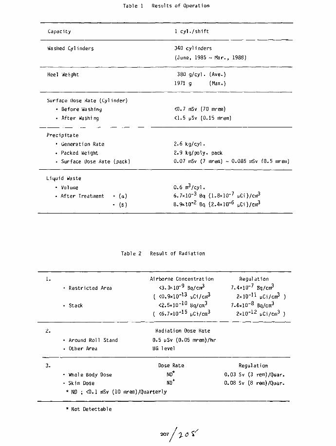
Table 1 Results of Operation
Capacity
Washed Cyl inders
Heel Weight
1 cy l . / sh i f t
340 cylinders
(June, 1985 ~ Mar., 1988)
380 g/cyl. (Ave.)
1971 g (Max.)
Surface Dose Kate (Cylinder)
• Before Washing
• After Washi ng
<0.7 mSv (70 mrem)
<1.5 pSv (0.15 mrem)
Precipitate
• Generation Rate
• Packed Weight
• Surface L)ose Rate (pack)
2.6 kg /cy l .
2.9 kg/poly, pack
0.07 mSv (7 mreni) 0.085 mSv (8.5 mrem)
Liquid Waste
• Volume• After Treatment (a)
(S)
0.6 m 3 / cy l .
6.7xlO"3 Bq (1 .8xlO" 7 yCi)/cm3
8.9xlO"2 Bq (2 .4x l (T 6 p C O / 3
Table 2 Result of Radiation
Restricted Area
Stack
Airborne Concentration
<3.3xlO'9 3q/cm3
( <0.9xl0"13 yCi/cm3
<2.5xlO'10 Bq/cm3
( <6.7xlO"15 pCi/cm3
Regulation
7.4xlO"7 Bq/cm3
2x lO" n yCi/cm3
7.4xlO-8 Bq/cm3
2xlO"12 uCi/cm3
2.
3.
• Arounc. Other
• Whole• Skin [
* ND ;
1 Rol
Area
Body
Jose
<0.1
1 Stand
Dose
mSv (10
Radiation
0.5 wSv (0.BG level
Dose Rate
ND*
ND*
mrem) /Quarterly
Dose Rate
05 mrem)/hr
0.030.08
Regulation
Sv (3 rem)/Quar.
Sv (8 reKi)/Quar.
* Not Detectable
2 0 7
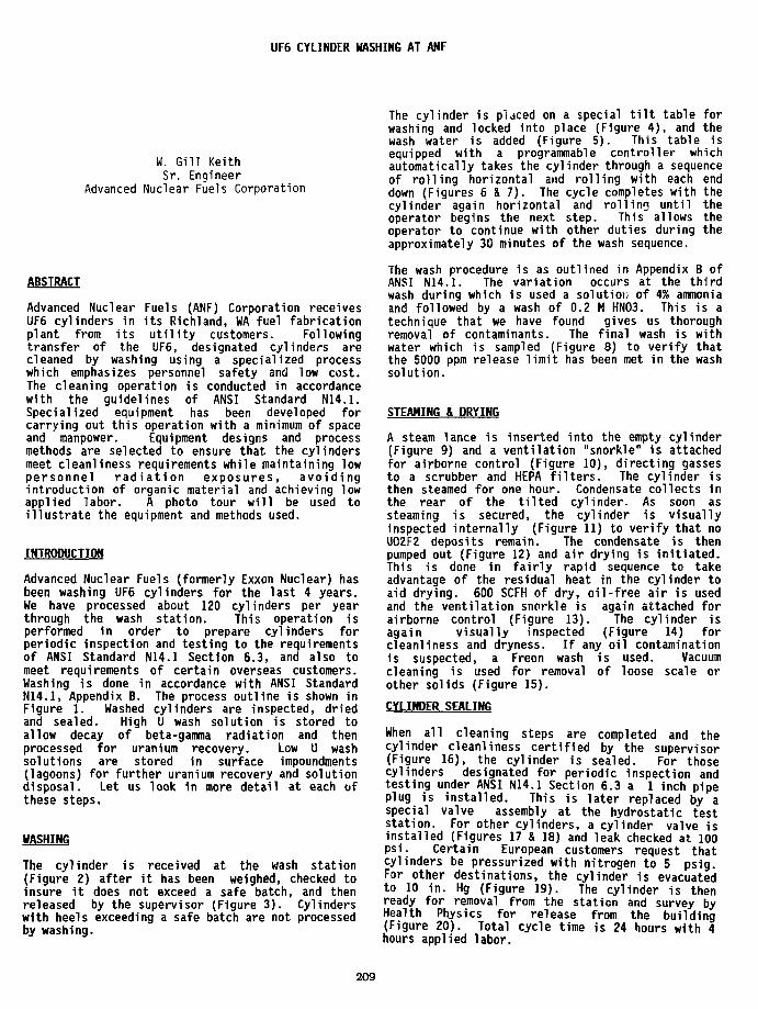
UF6 CYLINDER WASHING AT ANF
W. Gill KeithSr. Engineer
Advanced Nuclear Fuels Corporation
ABSTRACT
Advanced Nuclear Fuels (ANF) Corporation receivesUF6 cylinders in its Richland, WA fuel fabricationplant from its utility customers. Followingtransfer of the UF6, designated cylinders arecleaned by washing using a specialized processwhich emphasizes personnel safety and low cost.The cleaning operation is conducted in accordancewith the guidelines of ANSI Standard N14.1.Specialized equipment has been developed forcarrying out this operation with a minimum of spaceand manpower. Equipment designs and processmethods are selected to ensure that the cylindersmeet cleanliness requirements while maintaining lowpersonnel radiation exposures, avoidingintroduction of organic material and achieving lowapplied labor. A photo tour will be used toillustrate the equipment and methods used.
INTRODUCTION
Advanced Nuclear Fuels (formerly Exxon Nuclear) hasbeen washing UF6 cylinders for the last 4 years.We have processed about 120 cylinders per yearthrough the wash station. This operation isperformed in order to prepare cylinders forperiodic inspection and testing to the requirementsof ANSI Standard N14.1 Section 6.3, and also tomeet requirements of certain overseas customers.Washing is done in accordance with ANSI StandardN14.1, Appendix B. The process outline is shown inFigure 1. Washed cylinders are inspected, driedand sealed. High U wash solution is stored toallow decay of beta-gamma radiation and thenprocessed for uranium recovery. Low U washsolutions are stored in surface impoundments(lagoons) for further uranium recovery and solutiondisposal. Let us look in more detail at each ofthese steps.
WASHING
The cylinder is received at the wash station(Figure 2) after it has been weighed, checked toinsure it does not exceed a safe batch, and thenreleased by the supervisor (Figure 3). Cylinderswith heels exceeding a safe batch are not processedby washing.
The cylinder is placed on a special tilt table forwashing and locked into place (Figure 4), and thewash water is added (Figure 5). This table isequipped with a programmable controller whichautomatically takes the cylinder through a sequenceof rolling horizontal and rolling with each enddown (Figures 6 & 7). The cycle completes with thecylinder again horizontal and rolling until theoperator begins the next step. This allows theoperator to continue with other duties during theapproximately 30 minutes of the wash sequence.
The wash procedure is as outlined in Appendix B ofANSI N14.1. The variation occurs at the thirdwash during which is used a solution of 4% ammoniaand followed by a wash of 0.2 M HN03. This is atechnique that we have found gives us thoroughremoval of contaminants. The final wash is withwater which is sampled (Figure 8) to verify thatthe 5000 ppm release limit has been met in the washsolution.
STEAMING & DRYING
A steam lance is inserted into the empty cylinder(Figure 9) and a ventilation "snorkle" is attachedfor airborne control (Figure 10), directing gassesto a scrubber and HEPA filters. The cylinder isthen steamed for one hour. Condensate collects inthe rear of the tilted cylinder. As soon assteaming is secured, the cylinder is visuallyinspected internally (Figure 11) to verify that noU02F2 deposits remain. The condensate is thenpumped out (Figure 12) and air drying is initiated.This is done in fairly rapid sequence to takeadvantage of the residual heat in the cylinder toaid drying. 600 SCFH of dry, oil-free air is usedand the ventilation snorkle is again attached forairborne control (Figure 13). The cylinder isagain visually inspected (Figure 14) forcleanliness and dryness. If any oil contaminationis suspected, a Freon wash is used. Vacuumcleaning is used for removal of loose scale orother solids (Figure 15).
CYLINDER SEALING
When all cleaning steps are completed and thecylinder cleanliness certified by the supervisor(Figure 16), the cylinder is sealed. For thosecylinders designated for periodic inspection andtesting under ANSI N14.1 Section 6.3 a 1 inch pipeplug is installed. This is later replaced by aspecial valve assembly at the hydrostatic teststation. For other cylinders, a cylinder valve isinstalled (Figures 17 & 18) and leak checked at 100psi. Certain European customers request thatcylinders be pressurized with nitrogen to 5 psig.For other destinations, the cylinder is evacuatedto 10 in. Hg (Figure 19). The cylinder is thenready for removal from the station and survey byHealth Physics for release from the building(Figure 20). Total cycle time is 24 hours with 4hours applied labor.
209

LIQUID PROCESSING CONCLUSION
In light water reactor fuel fabrication we normallyencounter only alpha radiation sources. However,the vaporization process tends to leave behindless volatile decay products such as Thorium. Thisresults in requirements for special radiationmonitoring instrumentation at the wash station anda decay period being used on all wash solutionsprior to further processing.
The first two wash solutions contain the majorityof the uranium as well as the high beta/gammacontaminants. These solutions are pumped to aholding tank (Figure 21) and then, when washes from4 cylinders have been accumulated, transferred to aplastic 55-gallon drum (Figure 22). Drums,averaging 6.5 kg U each, are stored for at least 6months to allow daughter product decay. Followingthe storage period, solution from the drums ispumped back into the process area for recovery byADU precipitation, purification by solventextraction and return to working stock forsubsequent fabrication.
Wash solutions after the first two rinses arepumped to a storage lagoon (Figure 23) where theyare combined with other waste from the productionarea. These are eventually processed for uraniumand ammonia recovery and then discharged.
We have seen the equipment and processes used atANF for washing UF8 cylinders. The final productof this process is cylinders meeting thecleanliness requirements of ANSI N14.1. He areable to recover the full economic value of theheels and we are able to achieve this in a safe andeconomical fashion.
REFERENCE:
ANSI Standard N14.1-1982, American NationalStandard for Packaging of Uranium Hexafluoride forTransport.
RECEIVE
(CYL) (HI U LIQ)
STEAM WASH
1DRY
I(LOW U LIQ)
LAGOONSTORAGE
DRUM
1STORE
)
INSPECT RECOVER
SEAL PURIFY
EVACUATE WORKING STOCK
Figure 1
UF6 Cylinder Washing at ANFProcess Outline
210
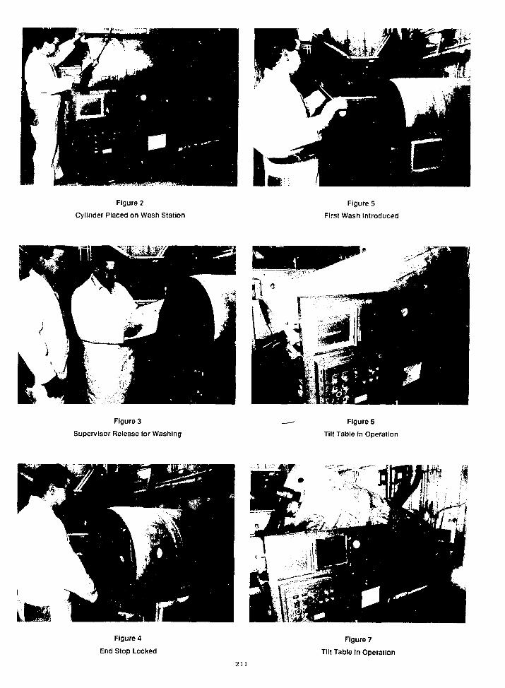
Figure 2
Cylinder Placed on Wash Station
Figure 5
First Wash Introduced
Figure 3
Supervisor Release for Washing
Figure 6
Tilt Table In Operation
Figure 4
End Stop Locked
Figure 7
Tilt Table In Operation
211
Figure 8
Wash Solution Sampled
Figure 11
Inspection Light Inserted
Figure 9
Steam Lance Inserted
Figure 12
Condensate Pumped Out
Figure 10
Exhaust Snorkle Attached
Figure 13
Air Drying
212
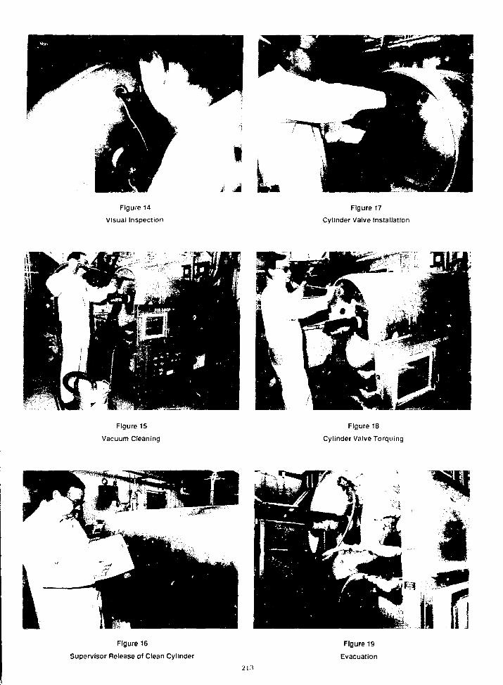
Figure 14
Visual Inspection
Figure 17
Cylinder Valve Installation
Figure 15
Vacuum Cleaning
Figure 18
Cylinder Valve Torquing
Figure 16
Supervisor Release of Clean Cylinder
Figure 19
Evacuation
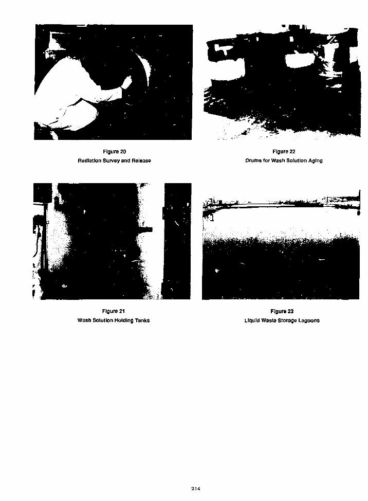
Figure 20
Radiation Survey and Release
Figure 22
Drums for Wash Solution Aging
Figure 21
Wash Solution Holding Tanks
Figure 23
Liquid Waste Storage Lagoons
214

UF6 CYLINDER INSPECTION AND TEST FACILITY AT PADUCAH GASEOUS DIFFUSION PUNT
G. W. LambW. N. Whinnery, III
Paducah Gaseous Diffusion PlantPaducah, Kentucky 42001
ABSTRACT
Paducah cylinder washing and testing facilityoperations are described for the cleaning of 10-and 14-ton uranium hexafluoride (UF6) cylinders.Decontamination solution preparation and maximumreuse of solution are explained. Cylinderinspection parameters before and after cleaning acylinder are detailed on data tables. Cleaningprocedures for a 10- and 14-ton cylinder areoutlined and the equipment is shown in photographsand process diagrams. A 12-point radiation surveyof the cylinder before and after cleaning is usedin protecting the worker and maintaining exposureto radiation as low as reasonably achievable(ALARA). The inspection of UF6 cylinders isrequired for new, In-service, and damagedcylinders as detailed In the criteria in ANSIN14.1 and Oak Ridge Operation ORO-651. Criteriaand inspection procedures for the replacement of1-inch UF6 cylinder valves and 1-inch and 1l/2-1nch cylinder plugs and the parameters forthread engagement of valves and plugs areoutlined. A uniform method of measurement forthread insertion made on both valves and plugs isdescribed. Specialized equipment to facilitateInstallation of the plug and valve and reduceworker exposure to undue hazards are described.Hydrostatic testing of cylinders, drying, andevacuation are part of the Chemical OperationsDepartment's function and they are presented inthe paper. Also discussed is the refurbishment of1-inch UF6 cylinder valves.
INTRODUCTION
Paducah cylinder Inspection and testing facilityoperations are described for 10- and 14-tonUF6 cylinders. The cylinder wash and testfacility is located 1n the Chemical Operationsbuilding at the Paducah Gaseous Diffusion Plant(PGDP). The system 1s designed as an always-safeunit for handling uranium up to 2.0 wt % U 2 3 5 .
Praparad by tha Paducah Guaoia OTIwIon Plant,Paducah. Kantucky 42001. oparatad by MARTINMARIETTA ENERGY SYSTEMS. INCORPORATED.lor tha U.S. DEPARTMENT OF ENERGY, undarContract No. 0E-AC0&84OR2U0D.
Tha submittad manuscript haj baan authorad by acontractor of tha U.S. Govammant undar Contract No.DE-AC05-UOR21400. Accordingly, lha U.S.Govammant raulnt a nonaxdutlva, royalty-traaKara* v> puUMi or raproouoa tha pubMiad torn otthk contribution, or aHow othan to do io, lor U.S.
I fflMIE PufpOMt-
The cylinder washing system consists of two150-gallon tanks, a solution spray and transferpump, a drain pan of proper slab thickness forcriticality control, spray nozzles, and evacuationconnections. An air-operated Milton Roy meteringpump is used to obtain and maintain the requiredhydrostatic test pressure. The drying system con-sists of an electrically heated enclosure, a dryair purge connection, dew point meters, and anevacuation jet.
DECONTAMINATION SOLUTION PREPARATION
The decontamination agent used in cylindercleaning is sodium carbonate. Decontaminationsolution preparation 1s accomplished by adding200 gallons of water to the east and west solutionstorage tanks and 100 pounds of sodium carbonate.The pH should be basic (9-11) and will be one ofthe parameters monitored to determine when thesolution should be rejuvenated. If the pH goesbelow 5, another 100 pounds of sodium carbonateshould be added to the solution. The pH ischecked in the solution before and after eachcylinder is washed. If ten cylinders have beencleaned since the last addition of soda ash, thenanother 100 pounds of sodium carbonate is addedunless the solution's pH is over 9. If theaddition of the 100 pounds of sodium carbonatedoes not bring the pH up above 7, then thesolution is ready to be changed. AnotherIndication of the level of contamination is thepressure gage reading from the spray pump whencirculating the cylinder cleaning solution. Thepressure of the clean solution is 60- to 70-poundgage. Pressure of a dirty solution ready to betransferred is 100- to 110-pound gage. Crystalformation in the pan is another sign that transferof solution may be required.
CLEANING PROCEDURES FOR A UF6 CYLINDER
A physical inspection of the cylinder to be washedis made to ensure that it has not been damaged.Nameplates which are badly corroded must bereplaced to ensure legibility. Also, the looserust is cleaned from the cylinder before placingit on the turning fixture to minimize contami-nation of the solution with iron.
Before and after washing the cylinder, dry surfaceradiation readings must be taken in 12 different
215
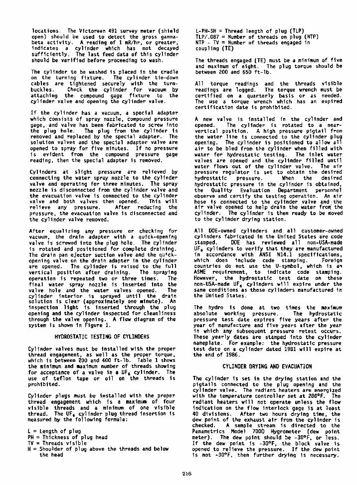
locations. The Victoreen 491 survey meter (shieldopen) should be used to detect the gross gamma-beta activity. A reading of 1 mR/hr, or greater,Indicates a cylinder which has not decayedsufficiently. The last feed data of this cylindershould be verified before proceeding to wash.
The cylinder to be washed Is placed In the cradleon the turning fixture. The cylinder tie-downcables are tightened securely with the turn-buckles. Check the cylinder for vacuum byattaching the compound gage fixture to thecylinder valve and opening the cylinder valve.
If the cylinder has a vacuum, a special adapterwhich consists of spray nozzle, compound pressuregage, and valve has been fabricated to screw Intothe plug hole. The plug from the cylinder isremoved and replaced by the special adapter. Thesolution valves and the special adapter valve areopened to spray for five minutes. If no pressureis evident from the compound pressure gagereading, then the special adapter 1s removed.
Cylinders at slight pressure are relieved byconnecting the water spray nozzle to the cylindervalve and operating for three minutes. The spraynozzle is disconnected from the cylinder valve andthe evacuation valve 1s connected to the cylindervalve and both valves then opened. This willrelieve any pressure. After reducing thepressure, the evacuation valve is disconnected andthe cylinder valve removed.
After equalizing any pressure or checking forvacuum, the drain adapter with a quick-openingvalve is screwed into the plug hole. The cylinderIs rotated and positioned for complete draining.The drain pan ejector suction valve and the qu<ck-opening valve on the drain adapter in the cylinderare opened. The cylinder 1s raised to the fullvertical position after draining. The sprayingoperation is repeated two or three times. Thefinal water spray nozzle Is inserted into thevalve hole and the water valves opened. Thecylinder interior is sprayed until the drainsolution is clear (approximately one minute). AnInspection light 1s Inserted through the plugopening and the cylinder Inspected for cleanlinessthrough the valve opening. A flow diagram of thesystem is shown in Figure 1.
HYDROSTATIC TESTING OF CYLINDERS
Cylinder valves must be Installed with the properthread engagement, as well as the proper torque,which Is between 200 and 400 ft-lb. Table 1 showsthe minimum and maximum number of threads showingfor acceptance of a valve 1n a UF6 cylinder. Theuse of teflon tape or oil on the threads isprohibited.
Cylinder plugs must be Installed with the properthread engagement which 1s a maximum of fourvisible threads and a minimum of one visiblethread. The UF( cylinder plug thread Insertion ismeasured by the following formula:
L = Length of plugPH = Thickness of plug headTV = Threads visibleH = Shoulder of plug above the threads and below
the head
L-PH-SH = Thread length of plug (TLP)TLP/.087 = Number of threads on plug (NTP)NTP - TV = Number of threads engaged 1ncoupling (TE)
The threads engaged (TE) must be a minimum of fiveand maximum of eight. The plug torque should bebetween 200 and 650 ft-lb.
All torque readings and the threads visiblereadings are logged. The torque wrench must becertified on a quarterly basis or as needed.The use a torque wrench which has an expiredcertification date is prohibited.
A new valve is installed in the cylinder andopened. The cylinder is rotated to a near-vertical position. A high pressure pigtail fromthe water line is connected to the cylinder plugopening. The cylinder is positioned to allow allair to be bled from the cylinder when filled withwater for hydrostatic testing. The Inlet watervalves are opened and the cylinder filled untilwater flows out of the cylinder valve. The airpressure regulator 1s set to obtain the desiredhydrostatic pressure. When the desiredhydrostatic pressure in the cylinder is obtained,the Quality Evaluation Department personnelobserve and certify the testing operation. An airhose is connected to the cylinder valve and theair valve opened to help drain the water front thecylinder. The cylinder 1s then ready to be movedto the cylinder drying station.
All DOE-owned cylinders and all customer-ownedcylinders fabricated 1n the United States are codestamped. DOE has reviewed all non-USA-madeUF6 cylinders to verify that they are manufacturedIn accordance with ANSI N14.1 specifications,which does Include code stamping. Foreigncountries do not use the U~symbol, which is anASME requirement, to indicate code stamping.However, the hydrostatic test date on thesenon-USA-made UF6 cylinders will expire under thesame conditions as those cylinders manufactured inthe United States.
The hydro 1s done at two times the maximumabsolute working pressure. The hydrostaticpressure test date expires five years after theyear of manufacture and five years after the yearin which any subsequent pressure retest occurs.These yearly dates are stamped into the cylindernameplate. For example: the hydrostatic pressuretest date on a cylinder dated 1981 will expire atthe end of 1986.
CYLINDER DRYING AND EVACUATION
The cylinder is set in the drying station and thepigtails connected to the plug opening and thecylinder valve. The radiant heaters are energizedwith the temperature controller set at 200°F. Theradiant heaters will not operate unless the flowindication on the flow interlock gage is at least40 divisions. After two hours drying time, thedew point of the exhaust air from the cylinder 1schecked. A sample stream is directed to thePanametHcs Model 700D Hygrometer (dew pointmeter). The dew point should be -30°F, or less.If the dew point is -30°F, the block valve isopened to relieve the pressure. If the dew point1s not -30°F, then further drying is necessary.
216

The pigtail Is removed from the plug end and aplug Installed In the cylinder. The cylinder 1spressurized to 80 ps1g and the area around theplug and the valve soap tested. When the cylinderIs airtight, the pressure 1s relieved. If 1t Isnecessary to tighten the plug or valve, thecylinder 1s evacuated to 20 Inches Hg. Thecylinder 1s removed from the drying stand and theofficial new tare weight established.
SOLUTION TRANSFER FROM THE WASHING SYSTEM
The wash solution 1s sampled for assay. Thesolution Is agitated thoroughly before sampling.If the assay 1s less than 1.0 wt % U 2 3 5 , thesolution Is safe to transfer to the storage tanksand onto the dissolvers. If the assay is>1.5 wt % U 2 3 S , the solution Is isotopicallydiluted by washing cylinders of lower assay.After verification of the assay and valving to theacidifying tanks, the solution 1s transferred,after it has heated to 120°F, to the 0-400recovery system. Three hundred gallons aretransferred to the two storage tanks and 150gallons for flushing out the drain pan and thelines to the acidifying tanks.
UF6 CYLINDER INSPECTION
An inspection 1s to be performed on anyUF6 cylinder prior to shipment from the plant orimmediately after receipt into the plant.UF6 cylinders covered include 10- and 14-toncylinders. Documentation of the results of thisinspection is to be made. The records of theinspection of any UFe Involved in any off-sitemovement on the UF6 Cylinder Inspection Data Sheet(UCN-9009) are recorded. A copy of this form isshown 1n Figure 2. Procedures and standards underwhich UF6 cylinders are Inspected, include ASME,ANSI N14.1, Oak Ridge Operation 0R0-651, PGDPQuality Evaluation (QE) SOPs QE-103 and QE-108.Cylinders are procured from qualified vendors.Vendor audit and surveillance are performedperiodically to assure adherence to specifi-cations. All new cylinders are inspected 100%visually. One cylinder per shipment 1s tested andInspected internally 100% upon receipt.
Any cylinder which 1s found to be unacceptable IsImmediately tagged. Cylinders which are found tobe damaged, overfilled, or to have a defectivevalve are to be tagged with a Defective CylinderTag (UCN-11300). Code stamped cylinders Involvedin off-site shipments, which are found to have anexpired hydrostatic pressure test date, are to betagged with a Hydrostatic Pressure Test DateExpired Tag (UCN-11301).
Shipment of cylinders 1s withheld from the carrierwhen any unacceptable damage or condition isfound. A customer-owned cylinder may be shippedoff-s1te if the hydrostatic pressure test date isexpired, providing it has a Hydrostatic PressureTest Date Expired Tag attached to the valve.
The Quality Evaluation Department will determinewhen a cylinder is found to have any unacceptabledamage as Indicated 1n Figure 3. The QualityEvaluation Department will make the final decisionas to whether the cylinder is acceptable orunacceptable and will record their decision bycompleting Section A at the bottom of Form
UCN-9009. Any qualifications for the use ofcylinders which are approved for limited use(until the defect(s) 1s corrected) must be entered1n Section A of Form UCN-9009.
It must be verified that all full cylinders havebeen allowed to cool until the UF6 contents havesolidified. The minimum cooling period for thesolidification of the UF6 contained 1n fullcylinders 1s five days for either 10- or 14-toncylinders.
A cold-pressure check is performed on the cylinderto be shipped using a compound pressure gage andcylinder valve adapter. All full or emptycylinders being shipped from the Paducah Plant areto be cold-pressure checked at ambient temperatureto assure that the Internal cylinder pressure isbelow atmosphere.
A tamper-proof device is Installed over thecylinder valve and a numbered seal affixed to thetamper-proof device.
PROCEDURE FOR REUSE OF CONTAMINATEDONE-INCH UF6 CYLINDER VALVES
Section 6.3.3 of ANSI N14.1-1982, AmericanNational Standard for Packaging of UraniumHexafluoride, permits the reuse of UF6 cylindervalves provided they are carefully Inspected andtested to verify their suitability for continueduse. Each cylinder valve 1s completelydisassembled. The outlet port cap gasket and thestem packing are discarded. Each valve componentis closely examined for obvious damage. The heatidentification number stamped on each valve bodyis examined and those valve bodies having a heatidentification number of 16, 17, 18, 19, 20, 21,or 22 are segregated. Using a .835-inch diameterplug gage, the bore of the inlet port of eachcylinder valve body 1s checked to verify that it1s not excessively necked-down. The minimum borediameter, anywhere along Its approximate 1.25-inchlength, should not be less than 0.835 Inches. Allpacking nuts are transported to the C-720 MachineShop area for stress relieving. The stress reliefoperation consists of the packing nuts attaining atemperature between 700 and 720°F and being heldat the temperature for a minimum of ninetyminutes. All valve components are decontaminated,Including the packing nuts which have been stressrelieved. Each set of valve components arereassembled per drawing E-J-11246, Revision 15.One or two drops of fluorinated lubricant areapplied to the Acme threads of each valve stem,and to the threads of the packing nut, prior totheir assembly. A 1/8-Inch high letter "R" 1sstamped Immediately below the alloy number 636 oneach valve body to designate that the valve hasbeen refurbished. Maintenance Division personnelshall tin the threads of each cylinder valve Inletport.
The Quality Evaluation Department 1s contacted andrequested to witness and certify the high pressureleak tests. The outlet port cap on etch valveoutlet port is assembled with 50 ft-lbs torque andinstalled in each valve at the high pressure leaktest fixture. The entire valve Is submerged in atest tank of water, the valve body 1s pressured to400 psig, and observed for leakage around the areawhere the stem exits the packing, around the
217
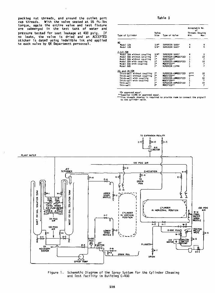
packing nut threads, and around the outlet portcap threads. With the valve seated at 55 ft-lbstorque, again the entire valve and test fixtureare submerged In the test tank of water andpressure tested for seat leakage at 400 ps1g. Ifno leaks, the valve 1s dried and an ACCEPTEDsticker is dated using Indelible Ink and appliedto each valve by QE Department personnel.
Table 1
Type of CylfnderValve
Type of Valve
Acceptable No.of
Threads ShowingM1n. Mas.
Model 12A 3/4"Hodel I2B 3/4"
2-1/2 TONModel 30A without coupling 3/4"Hodel 30A without coupling 1"Model 30A without coupling 1Model 30A with coupling 1Hodel 30A with coupling I1Model 30B 1
10- and 14-TONThick-will without coupling 1'Thick-wall without coupling 1Thick-wall with coupling 1Thick-wall with coupling 1Thin-wall 1Th1n-wall 1
SUPERIOR 5665-SUPERIOR 5665-
SUPERIOR 5665-SUPERIOR-UNMODIFIEDKODIFIEO"SUPERIOR-UNMODIFIEDMODIFIEO"SUPERIOR 11246
SUPERIOR-UNMODIFIEDMODIFIEO"SUPERIOR-UNMODIFIEDMODIFIED"SUPERIOR-UNMODIFIEDMODIFIEO"
91071077
10710
107
*0r approved equal."Superior 11246 or approved equal.*"F1ve threads showing 1s required to provide room to connect the pigtail
to the cylinder valve.
TO EXPANSION FACILITY
PLANT WATER
100 PSIGAIR
W-9v FINALWATERSPRAYNOZZLE
Figure 1. Schematic Diagram of the Spray System for the Cylinder Cleaningand Test Faci l i ty in Building C-400
218
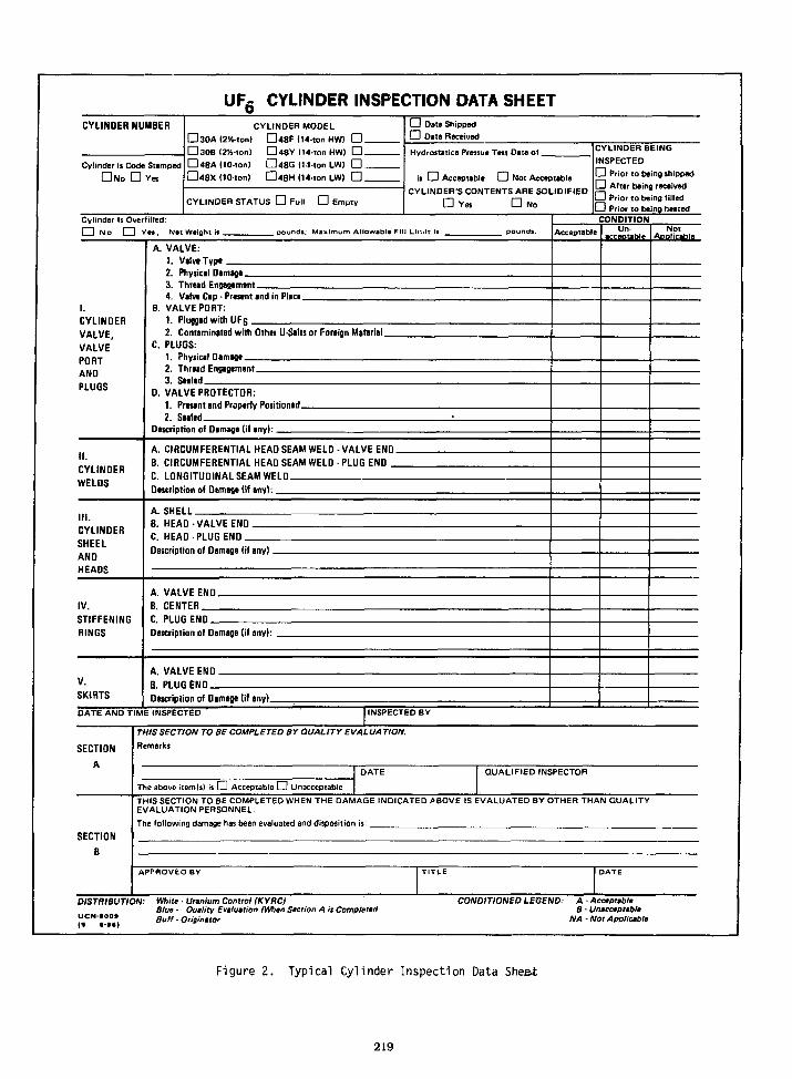
UF£ CYLINDER INSPECTION DATA SHEETCYLINOER NUMBER
Cylinder is Code Stamped• No D Yes
CYLINDER MODEL
• 3OA (254-ton) D48F (14-ton HW) D -• 30B <2K-ton) O48Y (14-ton HW) • _• 48A(10-tonl D48G (14-ton LW) D _D48X (10-ton) D4BH 114-ton LW> • _
CYLINDER STATUS • Full • Empty
LJ Date ShippedD Date Received
Hydrostatice Pressue Test Date of _
is D Acceptable D Not AcceptableCYLINDER'S CONTENTS ARE SOLIDIFIED
• Yes D NoCylinder Is Overfilled:I I N o Q Yn, N«t Weight is _ m pounds; MaxirT 1 Allowable Fill Lir..It Is
CYLINDER
VALVE,
VALVEPORTANDPLUGS
II.
CYLINDER
WELDS
III.CYLINDER
SHEELANDHEADS
IV.
STIFFENING
RINGS
V.
SKIRTS
A. VALVE:1. Valve T y p t .2. Physical Damage.3. Thread Engagement4. Valve Cap Present and in Place.
B. VALVE PORT:1. Plugged with UFg .2. Contaminated with Other U-Stlts or Foreign Material.
C. PLUGS:1. Physical Damage.2. Thread Engagement _3. Seeled
D. VALVE PROTECTOR:1. Present and Properly Positioned.2. Sealed
Description of Damage (if any):.
A. CIRCUMFERENTIAL HEAD SEAM WELO - VALVE END .
B. CIRCUMFERENTIAL HEAD SEAM WELD - PLUG END _
C. LONGITUDINAL SEAM WELDDescription of Damage (if any):
A. SHELLB. HEAD -VALVE ENDC. HEAD PLUG ENDDescription of Damage (if any).
A. VALVE ENDB. CENTER
C. PLUGENODescription of Damage (if any): .
A. VALVE END.
B. PLUG E N D _Description of Dimage (if any).
DATE AND TIME INSPECTED
SECTION
A
SECTION
B
CYLINDER BEINGINSPECTED
Prior to being shippedEH After being receivedLJ Prior to being filledD Prior to being heatedCONDITION
Acceptable Notl e Applicable
INSPECTED BY
THIS SECTION TO BE COMPLETED BY QUALITY EVALUA TION.
Remarks
The above item(s) is D Acceptable Q Unacceptable
QUALIFIED INSPECTOR
THIS SECTION TO BE COMPLETED WHEN THE DAMAGE INDICATED ABOVE IS EVALUATED BY OTHER THAN QUALITYEVALUATION PERSONNEL.
The following damage has been evaluated and disposition is:
APPROVED BY
DISTRIBUTION: White • Uranium Control (KYRC)Blue - Quality Evaluation (When Saction A is Completed
",C N""e" Buff-Originator
CONDITIONED LEGEND: A • AcceptableB • Unacceptable
NA - Not Applicable
Figure 2. Typical Cylinder Inspection Data Sheet
219

ACCEPTABLE DAMAGE UNACCEPTABLE DAMAGE
STIFFENER RING'ORN FROM S H E L L
IITHOUT REMOVALOF METAL
FROM SHELL
ACCEPTABLE DAMAGELESS THAN O S '
SHALLOW AND GENTLE
CURVED DENTS
ANT OEKT, VISKLE CRACK,IUt.SC OS SIGNIFICANT
REMOVAL OF METAL I0OUOIN0IIN OK ADJACENT TO ANTMEAD O« SEAM WELDRENDERS THE CTLINOER
UNACCEPTAiLE.
UNACCEPTABLE DAMAGE
J.SKIRT TOMN FROM HE«O
WITHOUT REMOVAL OF' ( • I METAL FROM HEAO A
SKIRT TOON FROM NEW| WITH REMOVAL OF• « E U L FRO* HE«O
F CTLINOER IS TO K U5E0M THE VERTICAL POSITION,
DENTS. CRACKS, OR OTHER OUUGCTO THE tOTTOM SKIRT
•MICH WULO IMMIR IT'SCAMaiLITr TO SUPPORT THE
CVLINOCR l« THE VERTICALPOSITION KOULO K UNACCEPMLE
CIRCUMFERENTIALHEAO - T O - SHELLSEAM HELD
nTV
^y
L.'ACCEPTABLE OAMAGE
SrUftP DCNTS
0 3 ' W
DEEP OBSHARP CURVED DENTS
GOUGES OR CUTS
VISIBLE CRACKS
LONGITUDINAL SHELL-TO - SHELLSEAM WELD
. . _ — — _ WELOEO JOINTS ARE SHOWN B»N U l t3~CR0SSHATCHlNG =— »l II
CTLINDERS WITH UNACCEPTABLE OAHAGEMAI B£ RETURNEO TO SERVICE AS FOLLOWS^ —
; < - - INDICATES ITEMS REOURINS ONLT THEREPLACEMENT OF THE OAMAGED PLUS AND/0*
VALVE PROVIDED NO DAMAGE HAS K E N DONETO THE HALF COUPLING
I- INDICATES ITEMS REOUMIN* ONLT REPAIROF THE SUSTAINED DAMAGE.
/ \ - INDICATES ITEMS REOURINS ftEPA* OF THESUSTAINEO OAMAOE FOLLOWED ST AHTDROSTATIC TEST
Figure 3. Examples of Acceptable and Unacceptable Damage to UFg Cylinders
220
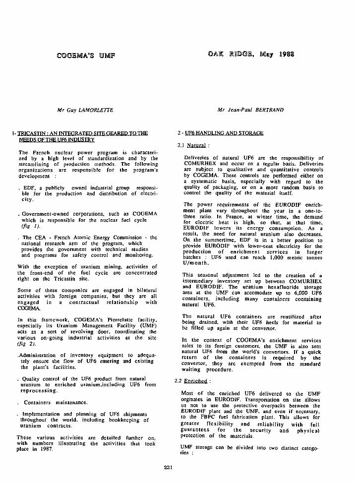
, May 1983
Mr Guy LAMORLETTE Mr Jean-Paul BERTRAND
1- TRICASTIN : AN INTEGRATED SITE GEARED TO THENEEDS OF THE UF6 INDUSTRY
The French nuclear power program is characteri-zed by a high level of standardization and by thestreamlining of production methods. The followingorganizations are responsible for the program'sdevelopment :
. EDF, a publicly owned industrial group responsi-ble for the production and distribution of electri-city.
. Government-owned corporations, such as COGEMAwhich is responsible for the nuclear fuel cycle(fig 1).
. The CEA - French Atomic Energy Commission - thenational research arm of the program, whichprovides the government with technical studiesand programs for safety control and monitoring.
With the exception of uranium mining, activities ofthe front-end of the fuel cycle are concentratedright on the Tricastin site.
Some of these companies are engaged in bilateralactivities with foreign companies, but they are allengaged in a contractual relationship withCOGEMA.
In this framework, COGEMA's Pierrelatte facility,especially its Uranium Management Facility (UMF)acts as a sort of revolving door, coordinating thevarious on-going industrial activities at the site(fig 2).
.Administration of inventory equipment to adequa-tely ensure the flow of UF6 entering and existingthe plant's facilities.
. Quality control of the UF6 product from naturaluranium to enriched uranium,including UF6 fromreprocess ing.
. Containers maintenance.
. Implementation and planning of UF6 shipmentsthroughout the world, including bookkeeping ofuranium contracts.
These various activities are detailed further on,with numbers illustrating the activities that tookplace in 1987.
2 - UF6 HANDLING AND STORAGE
2.1 Natural :
Deliveries of natural UF6 are the responsibility ofCOMURHEX and occur on a regular basis. Deliveriesare subject to qualitative and quantitative controlsby COGEMA. These controls are performed either ona systematic basis, especially with regard to thequality of packaging, or on a more random basis tocontrol the quality of the material itself.
The power requirements of the EURODIF enrich-ment plant vary throughout the year in a one-to-three ratio. In France, at winter time, the demandfor electric heat is high, so that, at that time,EURODIF lowers its energy consumption. As aresult, the need for natural uranium also decreases.On the summertime, EDF is in a better position toprovide EURODIF with lower-cost electricity for theproduction of enrichment services in largerbatches : UF6 used can reach 1,000 metric tonnesU/month .
This seasonal adjustment led to the creation of aintermediary inventory set up between COMURHEXand EURODIF. The uranium hexafluoride storagearea at the UMF can accomodate up to 6,000 UF6containers, including many containers containingnatural UF6.
The natural UF6 containers are reutilized afterbeing drained, with their UF6 heels for material tobe filled up again at the convenor.
In the context of COGEMA's enrichment servicessales to its foreign customers, the UMF is also sentnatural UF6 from the world's convenors. If a quickreturn of the containers is required by theconvenor, they are exempted from the standardwaiting procedure.
2.2 Enriched :
Most of the enriched UF6 delivered to the UMForginates in EURODIF. Transponalion on site allowsus not to use the protective overpacks between theEURODIF plant and the UMF, and even if necessary,to the FBFC fuel fabrication plant. This allows forgreater flexibility and reliability v/ith fullguarantees for the security and physicalprotection of the materials.
UMF storage can be divided into two distinct catego-ries :
221
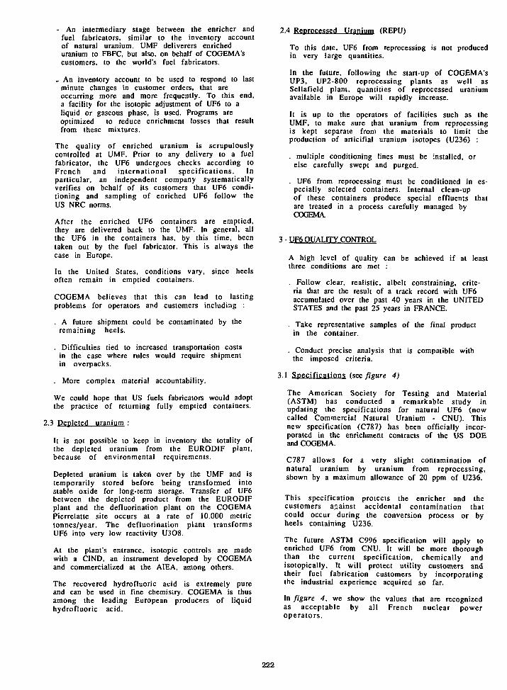
- An intermediary stage between the enricher andfuel fabricators, similar to the inventory accountof natural uranium. UMF deliverers enricheduranium to FBFC, but also, on behalf of COGEMA'scustomers, to the world's fuel fabricators.
_ An inventory account to be used to respond to lastminute changes in customer orders, that areoccurring more and more frequently. To this end,a facility for the isotopic adjustment of UF6 to aliquid or gaseous phase, is used. Programs areoptimized to reduce enrichment losses that resultfrom these mixtures.
The quality of enriched uranium is scrupulouslycontrolled at UMF. Prior to any delivery to a fuelfabricator, the UF6 undergoes checks according toFrench and international specifications. Inparticular, an independent company systematicallyverifies on behalf of its customers that UF6 condi-tioning and sampling of enriched UF6 follow theUS NRC norms.
After the enriched UF6 containers are emptied,they are delivered back to the UMF. In general, allthe UF6 in the containers has, by this time, beentaken out by the fuel fabricator. This is always thecase in Europe.
In the United States, conditions vary, since heelsoften remain in emptied containers.
COGEMA believes that this can lead to lastingproblems for operators and customers including :
. A future shipment could be contaminated by theremaining heels.
. Difficulties tied to increased transportation costsin the case where rules would require shipmentin overpacks.
. More complex material accountability.
We could hope that US fuels fabricators would adoptthe practice of returning fully emptied containers.
2.3 Depleted uranium :
It is not possible to keep in inventory the totality ofthe depleted uranium from the EURODIF plant,because of environmental requirements.
Depleted uranium is taken over by the UMF and istemporarily stored before being transformed intostable oxide for long-term storage. Transfer of UF6between the depleted product from the EURODIFplant and the defluorination plant on the COGEMAPierrelatte site occurs at a rate of 10.000 metrictonnes/year. The defluorination plant transformsUF6 into very low reactivity U3O8.
At the plant's entrance, isotopic controls are madewith a CIND, an instrument developed by COGEMAand commercialized at the AIEA, among others.
The recovered hydrofluoric acid is extremely pureand can be used in fine chemistry. COGEMA is thusamong the leading European producers of liquidhydrofluoric acid.
2.4 Reprocessed Uranium (REPU)
To this date, UF6 from reprocessing is not producedin very large quantities.
In the future, following the start-up of COGEMA'sUP3, UP2-800 reprocessing plants as well asSellafield plant, quantities of reprocessed uraniumavailable in Europe will rapidly increase.
It is up to the operators of facilities such as theUMF, to make sure that uranium from reprocessingis kept separate from the materials to limit theproduction of articifial uranium isotopes (U236) :
. multiple conditioning lines must be installed, orelse carefully swept and purged.
. UF6 from reprocessing must be conditioned in es-pecially selected containers. Internal clean-upof these containers produce special effluents thatare treated in a process carefully managed byCOGEMA.
3 - UF6 QUALITY CONTROL
A high level of quality can be achieved if at leastthree conditions are met :
. Follow clear, realistic, albeit constraining, crite-ria that are the result of a track record with UF6accumulated over the past 40 years in the UNITEDSTATES and the past 25 years in FRANCE.
. Take representative samples of the final productin the container.
. Conduct precise analysis that is compatible withthe imposed criteria.
3.1 Specifications (see figure 4)
The American Society for Testing and Material(ASTM) has conducted a remarkable study inupdating the specifications for natural UF6 (nowcalled Commercial Natural Uranium - CNU). Thisnew specification (C787) has been officially incor-porated in the enrichment contracts of the US DOEand COGEMA.
C787 allows for a very slight contamination ofnatural uranium by uranium from reprocessing,shown by a maximum allowance of 20 ppm of U236.
This specification protects the enricher and thecustomers against accidental contamination thatcould occur during the conversion process or byheels containing U236.
The future ASTM C996 specification will apply toenriched UF6 from CNU. It will be more thoroughthan the current specification, chemically andisotopically. It will protect utility customers andtheir fuel fabrication customers by incorporatingthe industrial experience acquired so far.
In figure 4, we show the values that are recognizedas acceptable by all French nuclear poweroperators.
222

3.2 Sampling :
Sampling should be a guarantee of the quality inthe container. In addition to sampling duringconditioning, UMF conducts :
. Very precise controls of the state of empty contai-ners, or containers with heels that could modifythe quality of the material.
. Sampling in the gaseous phase to analyze theisotopes, and in a liquid phase to isolate impuritiesof materials entering the COGEMA Pierrelatte site.
Depending on the customer requirements, the UMFcan conduct sampling on all models of existingsampling bottles, including models IS. 2S and P10tubes.
Following customer demands, samples performedby UMF are sent to customer selected later foranalysis.
The bottles are checked for tightness and cleanli-ness.
Maintenance operations include :
. rough vacui ,n julO"* lorr),
. passivation with C1F3,
. nitrogen filling.
At the end of the five years, the valves aredismantled, the bottles undergo a chemicalcleaning treatment, pressure and tightness test,and control of width measurements and welding.
3.3 Analysis :
The Quality Assurance Group manages the controland maintenance program and establishes rules.
These are described in detail in a QA program bookThey are similar in many cases to the ASTM methodas applied to up-to-date equipment.
Pack sampling bottle undergoes a subsamplingaccording to the diagram shown in Figure 5.
Halocarhon and volatile fluoride content :
Processes :. Infrared absorption spectrophotometry (P.E.S80). Detection threshold : 2 to 10 Vpm, depending on
molecules. Accuracy ± 5 % relative beyond detection
threshold
Isotopic Analysis :
Processes :A/ UF6 mass spectrometry : SMP 250
. Simple or double 235U-234U-U236 standard
. Detection threshold : 3 ppm
. Repeatability (external) : 0.005 % to 0.05 %
. Precision : 0.1 % relative concerning U5or. Accuracy : 1 % relative for U4.
The accuracy only depends on the standards used.COGEMA owns a very wide rang of standard. Thesestandards were compared with those prepared byNBS, BNFL, EURATOM.
The compatibility of all these is better that 10'3 forU5.
B/ Mass spectrometry with thermo-ion source :. Analysis of minor isotops : U4, U6. Accuracy : 2.10"3 (O.2 % absolute)
C/ Spectrometry :. U232 content (counting). Detection threshold : 0.01 ppb. Repeatability : ± 5 % at 0.1 ppb
V assay :
Process :. Gravimetry. U3O8 weighing compared with an ultra-pure U
metal standard submitted to the same operations.. Repeatability : 0.01 %. Test 4 times a year : conducted by a French
authority (CETAMA) related with severalEuropean laboratories.
Impurites :
Processes : very various, according to elements tobe counted, most particularly used are :
. ICP spectrometry
. Molecule absorption spcctrometry
. Atom absorption spectrometry
. Accuracy and repeatability can only be specifiedone element at a time. It varies from a few ppbto a few ppm.
COGEMA is preparing for the future by developinga one-of-a kind method which will replacetraditional subsampling as well as the waiting timeto obtain results on isotopic analysis.
4 - CONTAINERS
The quality of the UF6 product and the goal to fillup containers in a secure environment have ledCOGEMA to study these techniques and the cleaningmethods. It is the micro fluoration method.
4.1 The transfert/sampling Unit of UMF is based onthe "hot spot/cotd spot" process on each productionline.
One of the lines is equipped witfF a vacuum pumpentirely dry and leaktight, with an important flowand manufactured by NORMETEX. Temperature andpressure operating conditions make this unit aparticularly well-adapted device for evacuatingpossibly over-filled cylinders.
4.2 International and national regulations on pressu-rized equipment require security control everyfive years.
In FRANCE, containers designed following Frenchspecifications are under the control of theMinistry of Industry and Mine whose MiningDepartment is responsible for the program's imple-mentation. The ASME regulates containers that arebuilt according to foreign specifications. These twogroups operate in the same way, following interna-tional regulations.
223

Therefore, the UMF has at its disposal a maintenan-ce facility for 30B and 48Y containers with anannual capacity of 2,000 containers (Figure 6)Activities at the facility include :
- To perform internal cleaning through a highly-efficient process of high-pressure liquid uniqueaspersion : when necessary, the material contai-ned in heels may be recovered. Cleanliness ischecked by an authority not belonging toCOGEMA.
- To carry out external maintenance of packings,through shot-blasting, painting and ultra-sonicchecking of shell thickness, as well as systematicreplacing of related valves and plugs.
- To perform hydraulic pressure tests (28 barpressure), leaktightness test (7 bar pressure),vacuuming, nitrogen filling as well as finalweighing and tare-weighing operations.
- To conduct specific checks such as dye penetranttesting. X-ray test, coating thickness test.
5 - SECURITY AT UMF
In FRANCE, nuclear safety and security are gua-ranteed by two safety laws applicable to radiationionization and nuclear materials control : these twolaws are 76.663 of July 1976 and 80.572 of July 1980.
CEA INDUSTRIE
100%
COGEMA
CONVERSION
ENRICHMENT
FUEL FABRICATION
49%
51.5%
25%
CCMURHEX
EUROCXF
FBFC
These laws are applied through a series of decreesrelated to :
- Facilities and discharges to the environment- Basic Nuclear plants- Public safeguard- Workers safeguard- Capacitations- Measures- Nuclear material accountancy- Physical protection of these materials- Transports.
The Ministry of Industry is responsible to ensurethe implementation of these laws with thetechnical support of the "Institut de Protection etde Surete" Nucleaire" (IPSN). This group, whichoperates independently from the nuclearoperators, conducts strict controls in liaison withthe ADEA and EURATOM.
UMF is also organized along these lines : its storageareas are geographically separated and controlledcontinually by automatic surveillance systems. Inaddition, UMF benefits from the integration of theTricastin site, which regroups all of the activitieswe have talked about today.
1000TU
500TU
8000TU2500TL
9500 TU1500TU
7000TU*
Figure 1 : Companies located on Tricastin site Figure 2 : Main UF6 Flows In the Tricastin site
224

Figure 3
"Virgin"Natural
"Commercial"Natural
EnrichedCommercial
ISOTOPY
U232ppb/
Toul U
0
0,02
0.2
%U235
0.711
1.707 0715
3 *
ppm/UU234
55
<65
<300
ppm/UU236
0
<20
<300
CHEMISTRY
viol %/UF6HydroChloroC«rbon
<0.01
<0.0I
ppm/UBoron
<1
<4
* As an eiemple
Figure 4
1 tli) Bottlequid•npling
Sub-sampling
Liquid phase
Gaseous phase
Liquid phase
Liquid phase
Halocarbonsdosimetry
Isotopicanalysis
Uraniumcontent
Impureties
10g
eog
Figure 6
Figure 5

HISTORY OF UF6 HANDLING COMMITTEE
W. E. SykesPaducah Gaseous Diffusion Plant
Paducah, Kentucky 42001
ABSTRACT
UF6 handling operations at the Department ofEnergy (DOE) gaseous diffusion sites have beenperformed In a very safe manner since start-up ofuranium enrichment plants. Department of EnergyOak Ridge Operations office (DOE-ORO) and gaseousdiffusion plant contractor management were awareof the need to continue this safe level ofhandling performance and Identify new approachesfor further improvements of the overall safety ofUF6 handling. One such new approach was theformation of the UF6 Cylinder Handling Committeein 1973. The first major effort completed by thiscommittee was a comprehensive review of allUF6 handling activities at the three gaseousdiffusion plants. This review resulted 1n thedevelopment of 133 recommendations that describeprocedures or operating methods for safeUF6 handling operations. These recommendationsare still applicable and are intended to serve asa basis for safe UF6 handling practices at theDOE-ORO sites. Several of these recommendationshave resulted 1n significant Improvements insafety at the DOE sites and also to privatecompanies who have adopted the practices intotheir operating procedures and are covered 1n thisdocument. The UF6 Handling Committee continues tobe our main approach to interplant communicationaddressing problems and standardization of UF6handling related activities.
INTRODUCTION
From an overall standpoint, UF6 handlingoperations at the DOE gaseous diffusion sites havebeen performed In a very safe manner since start-up of uranium enrichment plants. Thousands ofUF6 cylinders have been filled, emptied, moved,sampled, and transferred.
Over the years, there has always been a strongemphasis toward promoting safe UF6 handling. BothDOE-ORO and gaseous diffusion plant contractor
Prapawf by tha Padvcah G M » Dltiutkn Plant.Paducari. Kantueky 42001. oparalad by MARTINMARIETTAENERGY SYSTEMS. INCORPORATED,lor tha U.S. DEPARTMENT OF ENERGY, undarContract No. DE-AC0M4OR21«».
Tha submMad manwcrlpl hat baan authorad by accntractwoflliaU.S.GcivaRKiMumtar Contract No.DE-AC05-WOR214O0. Accordingly, tha U.S.Gowrnmant rafafeis a mnaKchMlva. royaMy-traaHcanMlopUMIiornproducathapublkriadloTniolI f * comributlon. or aHow oUwi 10 do to. for U.S.Gowwrnrmnt Pufposat.
management, Union Carbide and Goodyear Atomic,were aware of the need to continue this safe levelof handling performance and hopefully Identify newapproaches to making further Improvements orenhancements of the overall safety of UF6 handlingat the gaseous diffusion sites. In 1973 a newapproach was Identified as an Idea that mightresult in such an Improvement. This Idea wasimplemented and what resulted is felt to have hada significant positive Impact toward enhancing theoverall safety performance of UF6 handling at thegaseous diffusion plants. This new approach wasthe formation of a UF6 Cylinder Handling Committeeto be composed of a representative from each ofthe three gaseous diffusion plants. Eachrepresentative was both a knowledgeable expert 1nthe various facets of UF6 handling and a high-level management member.
The Initial committee charter Included thefollowing points: review and evaluate UF6handling procedures and practices at the threesites to minimize the potential for UF6 releases,review UF6 release emergency procedures, recommendstandard methods and procedures for UF6 handlingat all three sites, and recommend Improvements Inequipment and facilities to achieve maximumprotection against UFe releases. The commitmentto the high level of effort in this area was madebecause plant management and DOE realized properand safe handling of UF6 was critical to theemerging social consciousness of the uraniumenrichment industry. During the late 1980s thetitle of this group was changed to the UF6Handling Committee. Even though the membershiphas changed over the years, the group's name haschanged and the committee size has Increased; itcontinues to serve as a coordinating group andcommunication vehicle on matters that relate tothe original purpose of the group.
The first major effort completed by this committeewas a comprehensive review of all UF6 handlingactivities at the three gaseous diffusion plantsto further ensure safe operations. This review,which required approximately 1-1/2 years tocomplete, resulted in the development of 133recommendations that describe procedures oroperating methods for safe UF. handlingoperations. These recommendations were publishedafter receiving agreement by top management fromthe three enrichment plants toward implementationwhere applicable at each site. The Implementation
227

period for these recommendations was approximatelyfive years. Since that time the recommendationshave received periodic status reviews at eachplant to ensure actions that were Intended to betaken were kept Intact. The last status review ofthe 133 recommendations was made In 1986 at allthe gaseous diffusion sites. These recommen-dations are still applicable and are Intended toserve as a basis for safe UF6 handling practicesat the DOE-ORO sites. These recommendations andseveral other Items developed by this committeesince 1973 were Incorporated Into the DOE documentORO-651, Revision 4, "Uranium Hexafluoride:Handling Procedures and Container Criteria," in1977. This information has provided guidance togroups worldwide.
The approach used in making the comprehensivereview was to divide all UF6 handling operationsinto 14 different areas for study. The following1s a 11st of the areas reviewed and a summary ofthe number of recommendations that resulted:
AREA
0n-S1te UF6 CylinderHandling
UF6 SamplingUFS FeedingCommunicationsEmergency Personnel
and EquipmentSecuring the ReleaseDecontaminationUF6 Transfer andAssay Blending
UF6 WithdrawalUF6 Cylinder IntegrityUF6 Cylinder Valve
Rebuilding and TestingUF6 Cylinder Valve
ReplacementContainmentUF6 Cylinder PigtailDesign and Testing
TOTAL
NUMBER OF RECOMMENDATIONS
1611116
891
101115
10
57
11133
A subcommittee made up of representatives from thethree plants for an area was assigned the task tocomplete a review and to Identify Important or keyprocedural steps or methods that if followed wouldprevent an Incident that could potentially resultIn a UF6 release. Past UF6 release-relatedincidents at the gaseous diffusion plants werereviewed. Lessons learned and/or actions taken toprevent the reoccurrence of a particular Incidentwere also used In the development of therecommendations. Each subcommittee provided theirfindings to the UF6 Cylinder Handling Committeefor review and approval. Once a recommendationwas accepted and approved, it was understood thateach plant would take prompt action whereapplicable to Incorporate It 1n their way ofperforming a particular task or activity. A fewof the recommendations that were Included werealready being performed at at least one of thesites but not consistently at all sites.
As previously stated these recommendations werewritten as a means to document an agreed-upon,approved, and consistent approach to the wayvarious UF6 handling related activities were to beperformed. To review all of these one by onewould take too long 1n a paper such as this. WhatI would like to do is cover several of the areasthat are included in the famous 133. Several ofthese key methods or approaches to operations haveresulted in significant Improvements 1n safety atthe DOE sites and also to private companies whohave adopted the practices Into their operatingprocedures.
The following are several examples ofrecommendations that are Included 1n eight of thefourteen areas:
On-S1te UF6 Cylinder Handling
• Any cylinder found to be 1n an unacceptablecondition, due to physical damage, oroverfilled should be appropriately taggedimmediately as this fact is determined. Tagsused to warn or provide Instruction are to beof a weather resistant type and secured withdurable wire.
• Liquid cylinders are to be cooled a standardtime of three days for 30-Inch and five daysfor 48-Inch before movement between buildings.Written Instructions giving approval arerequired If It is deemed necessary to move aliquid cylinder before this time period haselapsed.
• A cold.pressure check should be made on everycylinder before It 1s heated.
UF6 Sampling
• UF6 cylinders should always be heated with thevalve open to some pressure monitor with highand low standards which will alarm In theevent of an abnormal problem and shut off heat.Safety protection devices and alarms associatedwith cylinder heating should be tested andresults documented.
• Cylinders should always be thoroughly inspectedfor damage prior to heating. Extra attentionshould be given to the valve and plugs.Inspection results should be documented.
• The hazard of using open flame torches toprevent valve plugging in sampling operationswas recognized. It was recommended thatalternate methods be developed to eliminate theuse of torches.
UF6 Feeding
• Cylinder valves should never be opened unless1n full view of the person performing theoperation.
• Respiratory protection is required during theopening and closing of a UF6 system.
• Future designs for new autoclaves at the sitesshould include a device to manually close acylinder valve inside a closed autoclave.
228
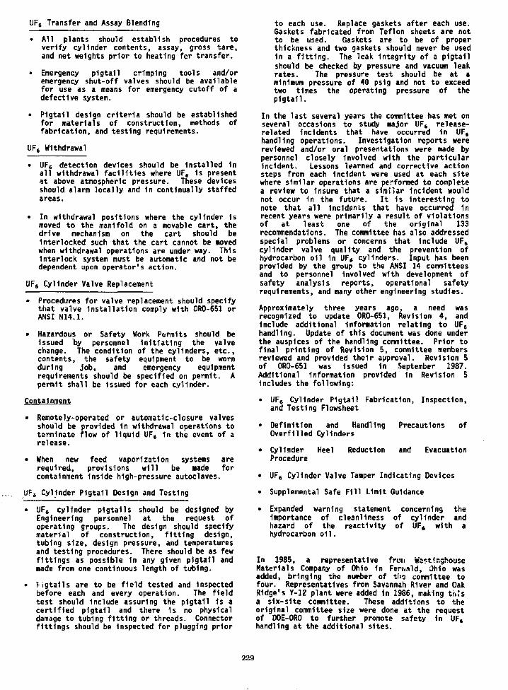
UF6 Transfer and Assay Blending
• All plants should establish procedures toverify cylinder contents, assay, gross tare,and net weights prior to heating for transfer.
• Emergency pigtail crimping tools and/oremergency shut-off valves should be availablefor use as a means for emergency cutoff of adefective system.
• Pigtail design criteria should be establishedfor materials of construction, methods offabrication, and testing requirements.
UF6 Withdrawal
• UFe detection devices should be installed Inall withdrawal facilities where UF6 Is presentat above atmospheric pressure. These devicesshould alarm locally and 1n continually staffedareas.
• In withdrawal positions where the cylinder Ismoved to the manifold on a movable cart, thedrive mechanism on the cart should beInterlocked such that the cart cannot be movedwhen withdrawal operations are under way. ThisInterlock system must be automatic and not bedependent upon operator's action.
UF6 Cylinder Valve Replacement
• Procedures for valve replacement should specifythat valve Installation comply with 0R0-651 orANSI N14.1.
• Hazardous or Safety Work Permits should beIssued by personnel Initiating the valvechange. The condition of the cylinders, etc.,contents, the safety equipment to be wornduring job, and emergency equipmentrequirements should be specified on permit. Apermit shall be issued for each cylinder.
Containment
• Remotely-operated or automatic-closure valvesshould be provided 1n withdrawal operations toterminate flow of liquid UF6 in the event of arelease.
• When new feed vaporization systems arerequired, provisions will be made forcontainment Inside high-pressure autoclaves.
UFS Cylinder Pigtail Design and Testing
• UF6 cylinder pigtails should be designed byEngineering personnel at the request ofoperating groups. The design should specifymaterial of construction, fitting design,tubing size, design pressure, and temperaturesand testing procedures. There should be as fewfittings as possible In any given pigtail andmade from one continuous length of tubing.
• Pigtails are to be field tested and Inspectedbefore each and every operation. The fieldtest should Include assuring the pigtail Is acertified pigtail and there 1s no physicaldamage to tubing fitting or threads. Connectorfittings should be Inspected for plugging prior
to each use. Replace gaskets after each use.Gaskets fabricated from Teflon sheets are notto be used. Gaskets are to be of properthickness and two gaskets should never be usedin a fitting. The leak integrity of a pigtailshould be checked by pressure and vacuum leakrates. The pressure test should be at aminimum pressure of 40 ps1g and not to exceedtwo times the operating pressure of thepigtail.
In the last several years the committee has met onseveral occasions to study major UFC release-related incidents that have occurred 1n UFthandling operations. Investigation reports werereviewed and/or oral presentations were made bypersonnel closely Involved with the particularIncident. Lessons learned and corrective actionsteps from each Incident were used at each sitewhere similar operations are performed to completea review to Insure that a similar Incident wouldnot occur in the future. It 1s Interesting tonote that all Incidents that have occurred 1nrecent years were primarily a result of violationsof at least one of the original 133recommendations. The committee has also addressedspecial problems or concerns that Include UF6cylinder valve quality and the prevention ofhydrocarbon oil 1n UFf cylinders. Input has beenprovided by the group to the ANSI 14 committeesand to personnel Involved with development ofsafety analysis reports, operational safetyrequirements, and many other engineering studies.
Approximately three years ago, a need wasrecognized to update 0R0-651, Revision 4, andInclude additional Information relating to UF(handling. Update of this document was done underthe auspices of the handling committee. Prior tofinal printing of Revision 5, committee membersreviewed and provided their approval. Revision 5of 0R0-651 was Issued in September 1987.Additional Information provided 1n Revision 5Includes the following:
• UFS Cylinder Pigtail Fabrication, Inspection,and Testing Flowsheet
• Definition and Handling Precautions ofOverfilled Cylinders
• Cylinder Heel Reduction and EvacuationProcedure
• UF6 Cylinder Valve Tamper Indicating Devices
• Supplemental Safe Fill Limit Guidance
• Expanded warning statement concerning theImportance of cleanliness of cylinder andhazard of the reactivity of UF6 with ahydrocarbon oil.
In 1985, a representative from West'nghouseMaterials Company of Ohio in Fernald, Ohio wasadded, bringing the number of tlra committee tofour. Representatives from Savannah River and OakRidge's Y-12 plant were added in 1986, making thisa s1x~s1te committee. These additions to theoriginal committee size were done at the requestof DOE-ORO to further promote safety 1n UF4handling at the additional sites.
229
In addition to the Handling Committee activitiesalready described in this paper, there have beenseveral longer term, special emphasis, or limitedscope problem areas that have been given attentionthrough the use of subcommittees to the maingroup. These subcommittees have been appointed towork, for periods as short as one to two months anda few have functioned for several years.
In February 1976 it became apparent to the UFGHandling Committee that each plant used slightlydifferent criteria for acceptable cylinder valvesas well as the cylinder valve bonnet nut. A UF6Cylinder, Valve, and Pigtail Committee wasformally established to generate a list that wouldbe approved for safe use.
Prior to this time several less formal Interplantcommittees met and contributed to the developmentof UF6 cylinders and valves. When this group wasreorganized 1n October 1978 a charter was puttogether that Included the following points.
• Maintain current specifications for procurementof cylinders and valves.
• Revise, as required, specifications to improvesafety or meet regulatory requirements.Handling Committee reviews all changes andapproves significant changes.
• Perform tests or evaluations, as requested bythe Handling Committee.
On subsequent occasions this subcommittee has beenrequested to evaluate the use of noncoded andrepaired UF6 cylinders at the three gaseousdiffusion sites, inspection criteria forUF6 cylinder valves to determine acceptability ateach site, and other Items. This subcommitteecontinues to be active and effectively functionsto address concerns and problems that addressprimarily UF6 cylinders and valves.
Other subcommittees have dealt with special areasthat Include Containment Autoclave Design andTesting Procedures, UF6 Cylinder Valve CloserDesign, and Sample and Transfer AutoclaveLubrication Study.
SUMMARY
Safe handling of UF6 continues to be of utmostImportance at the DOE-ORO sites. The UF( HandlingCommittee continues to be our main approach toInterplant communication addressing problemsand standardization of UF6 handling relatedactivities.
230
CONFIGURATION CONTROL OF SAFETY SYSTEMS
Ernest R. JohnsonMartin Marietta Energy Systems, Inc.
Paducah Gaseous Diffusion PlantPaducah, Kentucky
ABSTRACT
The Introduction of safety systems to the gaseousdiffusion plants gave rise to the need for somemethod of assuring that the testing,Identification, and changes to safety systems arereviewed and controlled by authorized personnel.This need has been satisfied through theImplementation of a configuration control system.The configuration control system Involves eachmajor division of the plant and provides a recordof the tests, maintenance activities and ahistorical record of these activities for eachsafety system.
DEFINITIONS
The best way to understand the use ofconfiguration control 1s to define the terms whichare used In Its Implementation.
Safety Systems - Safety systems are defined asequipment and/or hardware used to assure that theoperation of a facility will not r.'.v*eunacceptable risk to the safety and health ofemployees and the public.
Safety Analysis Report - A safety analysis report1s a document which provides specific Informationon how safety systems and administrative controlsprovide an acceptable level of safety for theoperation of a facility.
Administrative Controls - A procedural mechanismwhich requires action by a person rather than byequipment to perform a function similar to asafety system.
Operational Safety Requirement - Requirementswhich define how the safety systems are operatedand maintained and how administrative controls areImplemented.
Pnpmd by tfca Paducah Gamut DMiaton Plant.Paducah, KaMuoky 42001, oparalad by MARTINMARIETTA ENERGY SYSTEMS. INCORPORATED.lor tha U.S. DEPARTMENT OF ENERGY, undarContract No. 0E-AC0SMOR21400.
Tha llibmMad manuacnpl lua baan authorad by acontractor of tha U.S. Govamman*. undar Contract No.DE-AC05-MOR2140O. Accordingly, lha U.S.Govammant rataln* • nonaxduilva, royaky-fraaHcanaa to pubhh or raproduca tha pubkhad term ofti* contribution, or allow othant to do to, tar US.Govammant Purpotat.
Configuration Control - A system which assuresthat the testing, Identification, maintenance, andchanges to safety systems are reviewed andcontrolled by authorized personnel.
CONFIGURATION CONTROL IMPLEMENTATION
The Implementation of the configuration controlsystem begins during the conceptual design phaseof a project. Plant Engineering defines thesafety systems required to assure the safeoperation of the process or facility. TheIdentification of safety systems are done inconcert with the facility.
The existing facilities were given a thoroughreview as a part of the Safety Analysis programwhich was Initiated by the Department of Energy(DOE) during the early 1980 time frame. Theexisting facilities have been modified to reflectthe Safety System concept which was brought aboutby the Safety Analyses.
Engineering drawings are reviewed both In-houseand by DOE. The proposed safety systems aremarked on these drawings through the use of anopen "star" design. When the project is completedand the system Is accepted, the safety systems areIdentified withread.
a solid "star" which is easily
A second set of drawings are prepared followingthe acceptance by the operating division whichIdentifies each of the safety system components.The drawing legend contains the stores number,component name, reference drawing number, andinstrument setting if applicable.
Safety systems are purchased through the use of"data sheets" which are prepared by theEngineering Division. The data sheets are sent toPurchasing who establishes a safety systems storesnumber and marks the purchasing requisition with aspecial code to assure that special inspection isprovided for each component upon receipt atPaducah Gaseous Diffusion Plant (PGDP). Thespecial stores number 1s a unique number for aparticular component and remains with thatcomponent throughout Its usage and storage at theplant.
231
SAFETY SYSTEM IDENTIFICATION
When a safety system component is purchased andenters PGDP, it is inspected by the QualityEvaluation group and tagged with a "Spare SafetySystem Component" tag. The component Is thendelivered to the stores area where it is placed ina special safety system stores area. This area isfenced and locked to prevent usage of componentswithout authorization. In order to alertoperating and maintenance personnel of thepresence of a safety system component, thecomponents are marked with yellow tags to makethem more visible. These tags are placed on thecomponents following testing and acceptance by theoperating division. The Identification numberremains on the component at all times while thecomponent is in the system. The Identificationnumber is unique to that particular component and1s found on the safety system drawings.
SAFETY SYSTEM REPAIR
Repairs must be made to safety systems from timeto tine. The repair of safety system componentsIs one of the times when safety systems arevulnerable to mistakes. The Configuration ControlSystem has built in safeguards to lessen thisdanger.
First, when these systems must be repaired,tested, or changed, special permits called SafetySystem Work Permits are Issued by the operationssupervisor to the maintenance craft performing thework. This permit does not protect the Individualperforming the work from any hazards which mightbe involved. Protection for those Individualsperforming work on a system 1s provided throughthe use of hazardous or electrical work permits.The Safety System Work Permit alerts themaintenance personnel that they are working on asystem containing safety systems and specialhandling 1s required.
The second line of defense against mistakes is theuse of the Component Tagging System. If thecomponent cannot be field repaired, a newcomponent is purchased from safety system storesand installed in the system. The spare componenttag must be attached to the spare component or itwill not be accepted by the Maintenance Divisionfor installation in the system. When thecomponent is installed, the spare component tag isdestroyed, and the original, yellow safety systemtag is reinstalled on the new component.
A new spares component tag 1s placed on the partwhich was just removed from ths system, and theold part is delivered to the proper maintenanceshop for repair. When it is repaired, the tag ismarked to Indicate that inspection is required.Following acceptance by the Quality Evaluationgroup, the part is delivered to stores where it isplaced in safety system stores for storage in theproper catalog numbered bin.
Following repair of a safety system, the SafetySystem Work Permit 1s released by the propermaintenance supervision, and the system 1s testedto insure that it operates as designed.
If the component which had failed could not berepaired, the store's Inventory would reflect the
withdrawal of the component and a new item wouldbe purchased.
CHANGES TO SAFETY SYSTEMS
Changes to safety systems are not permitted untilthe changes are reviewed and approved byEngineering. The request for changes must be inwriting from the Operations Division manager tothe Engineering Division manager. The change 1sreviewed by the proper Engineering discipline, andthe reply 1s made in writing back to Operations bythe Engineering Division manager.
If the change requires revision of the safetydocumentation, DOE must also approve the changes.
The change control requirement of theConfiguration Control System insures the approvaland documentation of safety system changes andprovides a means of insuring that drawings areupdated when the changes are complete.
SAFETY SYSTEM DATA BASE
A safety system data base 1s maintained toschedule the testing of safety systems and toprovide a historical record of tests andmaintenance activity.
The data base 1s maintained on the ADP computersystem with scheduled testing printed monthly.The system at PGDP is similar to the one at OakRidge Gaseous Diffusion Plant (ORGDP).
Data input starts with the first-line supervisorwho completes a safety system data sheet each timeany safety system activity such as maintenance ortesting is performed. This sheet is nailed to acentral area and is entered on the computer. Thedata sheet has areas for testing only andmaintenance for maintenance activity. The systemallows recall of any of the data which has beenstored. The data can be recalled for delinquencyreports, calibration and testing, maintenanceactivity, or other desired information.
The data base is the workhorse of the testingsystem for safety systems.
SUMMARY
In summary, we have briefly discussed theConfiguration Control System as it is used atPGDP. The system provides many checks to Insurethat safety systems are not changed withoutauthorization from personnel who areknowledgeable and that they tested on anestablished schedule.
The methods employed are tagging safety systems,properly storing components with limited accessto them, and issuing safety system permits whichalert the maintenance personnel that they areworking on a system containing safety systems.Computerized records are maintained to providescheduled testing and maintenance of safetysystems.
232
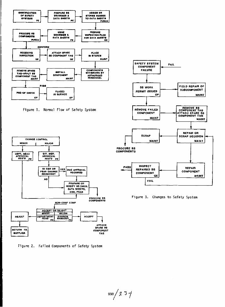
KHENTFtCATIONOP SAFETYSYSTEMS
PE
PROCURE 8S
COMPONENTSPORCH
RECE
PREPARE SSDRAWINGS *DATA SHEETS
PE
ISSUEDRAWMOS »
DATA SHEETSPE
ASSIGN SSSTORES NUMBERTO DATA SHEETS
PURCH
PREPAREINSPECTION PLAN
FOR DATA SHEETSOE
CONFORM
IVINQCTION
OE
REMOVE SPARETAG-APPLY SS
COMPONENT TAGMAINT
1 PASS
PHE-OP CHECK
OP
ATTACH SPARESS COMPONENT TAQ
QE
INSTALL
MAINT
PLACEDIN SERVICE
OP
PL*IN ST
CE
9RESMAINT
COMPONENTSWITHDRAWN BY
AUTHORIZEDPERSONNEL
Figure 1. Normal Flow of Safety System
CHANGE CONTROL
MINOS | MAJOR
DEPT. HEADAPPROVALREO'D pE
DIV. MOB.APPROVALREO'D P
IS OSR ORPSAR CHANGEREQUIRED?
YES DOE APPROVALREQUIRED
PREPARE ORMODIFY 38 DWQ3.
DATA SHEET8,OSR. PSAR
r
SAFETY SYSTEMCOMPONENT
FAILURE
SS WORK
PERMIT ISSUED
OP
REMOVE FAILEDCOMPONENT
MAINT
SCRAP
MAINT
FAIL
FIELD REPAIR OFSUBCOMPONENT
MAINT
REMOVE SSCOMPONENT TAQ
ATTACH SPARE SSCOMPONENT TAQ
MAINT
REPAIR ORSCRAP DECISION
MAINT
TPROCURE SSCOMPONENTS
PASS INSPECTREPAIRED S3COMPONENT
QE
REPAIR
COMPONENT
MAINT
FAIL
NON-CONF COMP
PROCURE SSCOMPONENTS
Figure 3. Changes to Safety System
REJECT
RETURN TOSUPPLIER
ACCEPT OR REJECT
DEPARTMENT DIVISIONMANAGEH
ATTACHSPARE SS
COMPONENTTAQ
Figure 2. Failed Components of Safety System
233
URANIUM HEXAFLUORIDE - EMERGENCY PREPAREDNESS IMPROVEMENTS
N. F. W1ndtMartin Marietta Energy Systems, Inc.
Paducah Gaseous Diffusion PlantPaducah, Kentucky 42001
ABSTRACT
The United States Enrichment Enterprise hassuccessfully handled uranium hexafluoride (UF6)for almost 40 years. However, recent events andlegislation have accelerated and emphasized therole of Emergency Preparedness. This paper willbriefly describe several recent Improvements 1nthe planning/training, Installation of newequipment, and public communications areas tofurther reduce the hazard potential of UF6. TheImprovements discussed are being implemented atthe Department of Energy's (DOE) Gaseous DiffusionPlant, located at Paducah, Kentucky and operatedby Martin Marietta Energy Systems, Inc.
The paper 1s organized Into three major areas:Planning/Training, New Equipment, and PublicCommunication. The paper Is designed as acollection of several emergency preparednessitems. The brief review of these Items shouldstimulate follow-up by interested parties.
Some of the planning/training items discussed areemergency squads and their training, the use ofdrills, tabletop exercises, emergency operationssimulations, and full-scale field exercisesutilizing mutual aid. Installation of newequipment will Include the latest In Impermeablesuits and respiratory protection equipment, publicwarning systems, C02 systems, cylinder patch kits,meteorological stations, TV monitors, and otheremergency operating center Improvements. Thepublic relations section will discuss theimplications of Installing a public warningsystem, Involvement 1n local planning committees(SARA-III), and the use of a Joint PublicInformation Center (JPIC).
INTRODUCTION
"Emergency Preparedness Improvements" 1s a subjectthat encompasses more than can be mentioned in an
Praparad by tha Paducah S U M DKIutkxi Plant,Paducah. Kwitudcy 42001, oparaMd by MARTINMARIETTA ENERGY SYSTEMS, INCORPORATED,to in. U.S. DEPARTMENT OF ENERGY. InterCOfflntc! No. DE-AC0S-MOR2U00.
Ttw aubmktad manuacript ha* baafl authored by acontractor oi ina U.S. Gowmmant undar Contract No.DE-AC05-84OR21400. Accordingly, tha U.S.Govarnmant retains a nonaxdutlva, royaHy-fraaHcanaa to puUMi or raproduca tha pubMhad mm ofthU contribution, or aHow othan to do w, for U.S.GovamrTMt-A PurpoMa.
article of this magnitude. The approach taken inthis presentation was to collect and consolidateassorted Improvements. This compilation shouldhelp put into perspective the risk of aUF6 release and allow the reader to consider thevalue of emergency preparedness activities. TheImprovements will show both factors Involved 1nrisk assessment; likelihood and consequence, to besignificantly reduced. The Paducah Plant 1s lesslikely, than in the past, to have a majorUF6 release and is better prepared should one everoccur.
PLANNING/TRAINING IMPROVEMENTS
The Paducah Plant has basically operated withthe same emergency preparedness philosophy forover 35 years; this philosophy has been verysuccessful. Line organizations have majorresponsibility within their areas. Prompt localaction Is required In these areas. Overallplantwide emergency direction 1s always providedby the Plant Shift Superintendent (PSS) who isthe Plant Emergency Director. All shiftorganizations must be capable of handlingemergencies at any time. Designated emergencyresponse squads both local and plantwide mustcontinually receive training and practice.
There have always been training and responsedrills conducted by all shift organizations.Currently, training has been expanded to includethe following techniques:
• 40 hours of emergency training conducted byoff-site experts annually.
• At least 24 hours of training by on-sitepersonnel annually.
• Emergency response drills performed on allshifts.
• Emergency Management Exercises (EME) utilizingthe emergency cadre, role players, emergencysquads, and security forces conductedquarterly.
• Use of a new "tabletop" concept for exercisingplans and procedures on-site, off-site, and incombination without the actual movement ofemergency equipment.
235
• Major full-scale field exercises Including off-site agencies. This years1 exercise Is titled"Readiness '88."
Planning concepts have also changed over theyears. Currently planning has a much broaderbase. The use of consultants, the Increase 1nmutual aid, Involvement 1n local planningcommittees, and meeting the requirements ofSARA-THle III. The area of Public Information1s shaping emergency planning more than ever.
Conclusion of this section would not be completewithout mention of Readiness '88, a completetest of the planning and training functions.Readiness '88 1s a full-scale field exercisedesigned to test the coordinated emergencyresponse of Martin Marietta Energy Systems, Inc.,the U.S. Department of Energy (DOE), McCrackenCounty, Ballard County, Illinois, and Kentucky andwill be conducted May 14, 1988. The exercise 1sbeing coordinated by the Paducah Gaseous DiffusionPlant. The Intent 1s to test and refineprocedures designed to protect the public andemployees 1n the unlikely event of a major plantemergency. Readiness '88 Is a checkpoint alongthe way to an effective emergency preparednessprogram. Plans and procedures have been writtenor modified, tabletop exercises and responsedrills have been conducted. More than 300 peopleare expected to be Involved 1n a test of jointcapability. Readiness '88 1s the most extensiveexercise of Its kind 1n the plant's history.
NEW EQUIPMENT
New equipment varies from windsocks to com-puterized meteorological plume analysis systems.In an attempt to organize, new equipment will besubdivided Into three categories: prevention,detection, and mitigation. A listing and briefdescription 1s all that 1s possible for thisarticle. Hopefully this brief review willstimulate follow-up by Interested parties.
Prevention Type Equipment
• Cranes - ant1-coll1s1on, radio-controlled, 360°rotation, and Improved, double-hook liftingdevices.
• Cylinder storage yards - Increased storageareas allow "clear path" movement with cylin-ders at minimum height without moving cylindersover other cylinders. Yard design alsorestricts vehicular access.
• Containment systems - autoclaves, buildings,dykes, Inflatable drain line plugs.
• Safety systems - Most critical systems,especially those operating above atmosphericpressure, have been modified to comply with thesafety system concept. Items such as redundantwater Inventory, high pressure, low pressure,and a pressure and cylinder cart movementInterlock are In place.
• Inventory reduction - HF storage tanks reducedfrom 28,000 pounds to 800 pounds.
• Atmospheric vents - solid sorbent trappingmedia added on all vents to the atmosphere plus
redundant Instrument monitoring such as con-tinuous wet chemical bubblers, real-time alphaparticle analysis, Infrared and acousticanalysis, and TV cameras.
• Noimetex pumps - These Internally sealed pumpshave been Installed In high pressure liquefac-tion applications, greatly reducing maintenanceand the potential for leaks to the atmosphere.
Detection Type Equipment
• UF6 sensors 1n process areas - monitor, alarm,and shutdown capability.
• Conductivity monitoring of autoclaves steamcondensate - alarm and shutdown capability.
• Cylinder pressure - high and low alarm andshutdown capability.
• Autoclave pressure - high alarm and shutdowncapability.
• TV cameras - visual surveillance and alarmed.
• Vibration detection - monitors, alarm, andshutdown capability of critical rotatingequipment.
Mitigation Type Eauipment
• New Impermeable suit - Vautex, three-layercomposite of viton, nylon, and neoprene.
• Respirators - full-face respirators, whichutilize a larger cannister, rather than theone-half face are now being specified by themanufacturer. A new 10-minute escape only maskhas been made available 1n specified areas.
• Large C0a system - 12,000 pounds of liquidCOj available to contain or control leaks fromhot UFt cylinders.
• Prototype cylinder patch - much lighter 1nweight, more effective sealing design, andfaster to Install.
• Emergency operating center Improvements -status boards, ring-down phones, personal com-puters, historian, telefax, back-up radiocommunications, Improved maps and procedures,and Improvements to the plant public addresssystem.
• Meteorological stations - Computer-generatedplume release models.
• Windsocks - 11 plant locations.
• Public warning sirens - two-mile notificationof the public to shelter followed by EmergencyBroadcast System (EBS) messages.
PUBLIC COMMUNICATIONS
Emergency preparedness Improvements in the areaof Public Communications are now mandated byFederal law. The Emergency Planning andCommunity Right-To-Know Act of 1986 (Title III)of the Superfund Amendments and Reauthor1zat1onAct (SARA) mandates that local citizens will
236
have ready access to information from chemicalfacilities. This Information Includes whichchemicals are produced or handled and 1n whatamounts, how much 1s released, and when spillshave occurred. Title III also dictates thatcompanies work with communities on EmergencyPlanning and give states, counties, and localfire departments Information and a voice 1nchemical handling decisions. The Paducah PlantIs building on years of experience 1n emergencypreparedness and long established workingrelationships between the plant and off-siteemergency agencies. Some of the highlights inpublic communication follow:
Public Warning System - A fixed siren systemcovering all of the two-mile Immediate notifica-tion zone alerts residents to shelter and listenfor further Instructions on an EBS station. Priorto placing this system in service, a public Infor-mation program which included new procedures forthe plant and county emergency plans and door-to-door distribution of an information pamphlet tolocal residents was conducted.
Local Planning Committees - The plant EmergencyPreparedness Coordinator serves as a committeemember on the local planning committees of bothneighboring counties. We have been decliningthe chairmanship of these committees, but aretaking a very active and supportive role.
Joint Public Information Center (JPIC) - ThePaducah Gaseous Diffusion Plant has recentlyestablished an off-site JPIC. The JPIC is aplace at which all information concerning anemergency is officially released from all
Involved agencies or groups. The JPIC 1s thecentralized source of official Information withthe following responsibilities:
• Confirm emergency information with the media.
• Draft/issue press releases.
• Conduct press conferences.
• Staff rumor control phone banks.
• Manage live media coverage.
A well-equipped JPIC includes a large (100-200persons) media briefing room, phones for themedia, news hot lines, citizen hot lines, TVmonitors, radio monitors, media work tables, TVcamera areas, briefers' table, podium, technicalexperts, and agency public information officers'work rooms.
CONCLUSIONS
The United States Enrichment Enterprise hassuccessfully handled uranium hexafluoride foralmost 40 years. Improvements have continuallybeen made which lessen both the likelihood andconsequences of a major UF6 release. We cannot becontent with our past achievements and ceaseefforts toward further Improvements. We must con-tinue to balance the existing risks againstincreases in production costs. It behooves usall to continue to seek reasonable emergency pre-paredness improvements in a cost-effective manner.
237 / X "3 V

ACKNOWLEDGEMENTS
We wish to express our appreciation to the individuals who have conscientiously contributed to the
compilation and publication of the conference proceedings. Specifically, we would like to thank Jan S.
Stamey, William L. Capshaw, and Karen M. Morton (K-25 Graphic Arts Department) and the K-25 Central
Printing Staff.
William D. Strunk, Technical Coordinator
Sheila G. Thornton, Administrative Coordinator
239 A / - / C
Related Documents