CtrlFlow - Distributed IoT Thermo System Yoseph Hassan, Joseph Mansy, Muhamad Elassar, Vinh Tran Dept. of Electrical Engineering and Computer Science, University of Central Florida, Orlando, Florida, 32816-2450 Abstract — This paper is representative of all of the methods and techniques used in developing and designing a small scale representation of an Internet of Things smart thermo system. This will delve into not only the hardware associated with the design but also the software component as well as the testing and administrative procedures put in place throughout the duration of the project. This project allows for users of the system to control different temperatures in different rooms based on their individual needs. This is performed via a mobile application component which allows for remote control of the specific temperatures in each room. These rooms are equipped with specially made vents connected to microcontrollers which affect the opening and closing of these vents. These temperatures cannot be controlled concurrently but rather are staggered after completing the request of temperature change of one room and moving on to the other. Temperatures can be mostly maintained by closing vents and preserving the current temperature. I. INTRODUCTION In Florida and other regions where temperatures can significantly affect comfort greatly, modern HVAC systems are simply not providing an adequate solution. These systems typically cool on full blast until the desired temperature is reached and then turn off. This process obviously has its downfalls as it is quite primitive in its approach to heating and cooling. Individuals often require different temperatures to meet their comfort needs and while these systems help mitigate the issue by allowing for some version of temperature control they are far from a comprehensive solution which allows for users to have more personalized management of their respective rooms. Our product was conceived to further lessen the issues mentioned earlier and also provide a bit more convenience to actually controlling the temperature. This is accomplished via connecting several microcontrollers to a main hub then connecting the auxiliary microcontrollers to specially made vents which open or close depending on the current temperature of the room and the target temp to be reached by the heating/cooling apparatus. All of the hardware in the system is expected to communicate wirelessly via LoRa. Apart from the boards communicating between themselves wirelessly we also allowed for wireless communication between the boards and the mobile device controlling the temperatures of the rooms. This decision was based on improved convenience as it would be inconvenient for users to have to access an immobile device to alter temperature. The wireless nature of the project is to promote easier setup for the user and prevent unnecessary wire clutter throughout the home. This falls under further convenience to create an easy to use environment for inexperienced users. The expectation of this project is to provide a small scale representation of a home to provide a proof of concept of what can be relatively easily accomplished in a full scale implementation of the design. Given the maximum range of the LoRa standard the design would not require much modification in order to be applied in a full scale setting as in an actual modern home the distances between the boards would be much more significant than in the model. II. SYSTEM COMPONENTS A. Internet of Things (IoT) The Internet of Things, or IoT, describes the network of billions of physical devices that are connected to the internet, all collecting and sharing data. These devices are known as “things” and are embedded with sensors, software, and other technologies. They also are provided with unique identifiers (UIDs) and the ability to transfer data over a network without requiring human-to-human or human-to-computer interaction. Thanks to extremely cheap computer chips and the ubiquity of wireless networks, it’s possible to turn anything, from something as small as a pen to something as big as a cruise ship, into a part of the IoT. Fig. 0. Internet of things diagram representation.

Welcome message from author
This document is posted to help you gain knowledge. Please leave a comment to let me know what you think about it! Share it to your friends and learn new things together.
Transcript
CtrlFlow - Distributed IoTThermo System
Yoseph Hassan, Joseph Mansy, MuhamadElassar, Vinh Tran
Dept. of Electrical Engineering and ComputerScience, University of Central Florida, Orlando,
Florida, 32816-2450
Abstract — This paper is representative of all of themethods and techniques used in developing and designing asmall scale representation of an Internet of Things smartthermo system. This will delve into not only the hardwareassociated with the design but also the software componentas well as the testing and administrative procedures put inplace throughout the duration of the project. This projectallows for users of the system to control differenttemperatures in different rooms based on their individualneeds. This is performed via a mobile application componentwhich allows for remote control of the specific temperaturesin each room. These rooms are equipped with specially madevents connected to microcontrollers which affect the openingand closing of these vents. These temperatures cannot becontrolled concurrently but rather are staggered aftercompleting the request of temperature change of one roomand moving on to the other. Temperatures can be mostlymaintained by closing vents and preserving the currenttemperature.
I. INTRODUCTION
In Florida and other regions where temperatures cansignificantly affect comfort greatly, modern HVACsystems are simply not providing an adequate solution.These systems typically cool on full blast until the desiredtemperature is reached and then turn off. This processobviously has its downfalls as it is quite primitive in itsapproach to heating and cooling. Individuals often requiredifferent temperatures to meet their comfort needs andwhile these systems help mitigate the issue by allowing forsome version of temperature control they are far from acomprehensive solution which allows for users to havemore personalized management of their respective rooms.Our product was conceived to further lessen the issuesmentioned earlier and also provide a bit more convenienceto actually controlling the temperature. This isaccomplished via connecting several microcontrollers to amain hub then connecting the auxiliary microcontrollers tospecially made vents which open or close depending onthe current temperature of the room and the target temp tobe reached by the heating/cooling apparatus. All of the
hardware in the system is expected to communicatewirelessly via LoRa. Apart from the boardscommunicating between themselves wirelessly we alsoallowed for wireless communication between the boardsand the mobile device controlling the temperatures of therooms. This decision was based on improved convenienceas it would be inconvenient for users to have to access animmobile device to alter temperature.
The wireless nature of the project is to promote easiersetup for the user and prevent unnecessary wire clutterthroughout the home. This falls under further convenienceto create an easy to use environment for inexperiencedusers.
The expectation of this project is to provide a smallscale representation of a home to provide a proof ofconcept of what can be relatively easily accomplished in afull scale implementation of the design. Given themaximum range of the LoRa standard the design wouldnot require much modification in order to be applied in afull scale setting as in an actual modern home thedistances between the boards would be much moresignificant than in the model.
II. SYSTEM COMPONENTS
A. Internet of Things (IoT)
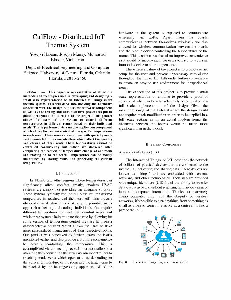
The Internet of Things, or IoT, describes the networkof billions of physical devices that are connected to theinternet, all collecting and sharing data. These devices areknown as “things” and are embedded with sensors,software, and other technologies. They also are providedwith unique identifiers (UIDs) and the ability to transferdata over a network without requiring human-to-human orhuman-to-computer interaction. Thanks to extremelycheap computer chips and the ubiquity of wirelessnetworks, it’s possible to turn anything, from something assmall as a pen to something as big as a cruise ship, into apart of the IoT.
Fig. 0. Internet of things diagram representation.
The smart devices that are intermittently connectedthrough IoT share the data that they collected to an IoTgateway or other edge device where the data is then sent tothe cloud to be analyzed and managed. In our case, weonly require one smart device to be connected throughIoT, the central hub thermostat. However, in some casesthese devices communicate and share information withother devices that are related and perform actions based onthe data they receive from one another. Being within anIoT network allows the devices to do the heavy liftingwithout any human action required. However, people caninteract with the devices. For this project, the user will setup the central hub thermostat and control the temperaturesin each room using it.
The simplest way to dive into the IoT network and getdevices set up to communicate with each other is to use anIoT platform. An IoT platform gives developers a headstart in incorporating their smart devices into an IoTsystem by providing built-in tools, features, andcapabilities to make the life cycle of IoT a lot easier andless costly for the consumer. There are many big techcompanies today that have developed their own IoTplatforms for developers to delve into, with lots ofprovided documentation and big community support. TheIoT platform used for this project is Arduino IoT Cloud.
B. Microcontroller
One of the most crucial components in our design isthe microcontroller we chose for our circuit boards asthese were what would be used throughout all of theboards throughout the distributed system. Thesemicrocontrollers are in charge of processing all of thelogic we implemented into our project therefore makingthem an integral part of the overall design andimplementation.
The microcontroller we decided to move forward withwas the ATSAMD21G18A-AUT. Our reasoning behindusing this chip is that the SAMD21 chips inherit most ofthe benefits of the aforementioned ATMega4809 whilebeing faster and more power efficient. More importantlythis MCU has many more configurations than really any ofthe other MCUs we had encountered when researching.There are several configurations that offer more or lesspins and different program memory capacities. This isuseful as we can use the same development environmentand choose the MCU that best fits our needs for eachseparate device and optimize cost.
C. Thermoelectric Modules
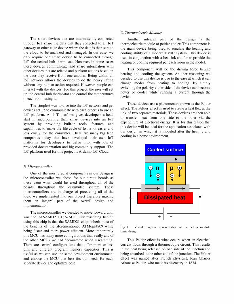
Another integral part of the design is thethermoelectric module or peltier cooler. This component isthe main device being used to emulate the heating andcooling ability of a modern HVAC system. This device isused in conjunction with a heatsink and fan to provide theheating or cooling required per each room in the model.
This component will be the driving force behindheating and cooling the system. Another reasoning wedecided to use this device is due to the ease at which it canchange modes from heating to cooling. By simplyswitching the polarity either side of the device can becomehotter or cooler while running a current through thedevice.
These devices use a phenomenon known as the Peltiereffect. The Peltier effect is used to create a heat flux at thelink of two separate materials. These devices are then ableto transfer heat from one side to the other via theexpenditure of electrical energy. It is for this reason thatthis device will be ideal for the application associated withour design in which it is modeled after the heating andcooling in a home environment.
Fig. 1. Visual diagram representation of the peltier modulebasic design.
This Peltier effect is what occurs when an electricalcurrent flows through a thermocouple circuit. This resultsin the heat being released on one side of the junction andbeing absorbed at the other end of the junction. The Peltiereffect was named after French physicist, Jean CharlesAthanase Peltier, who made its discovery in 1834.
The Equation associated with Peltier heat is shownbelow:
(1)𝑄 = (Π𝐴
− Π𝐵
) 𝐼
Such that A and B are conductors, A and B are thePeltier coefficients of their respective conductors, and I isthe electrical current from conductors A to B. These Peltiercoefficients are measurements in terms of the amount ofheat which is carried per unit charge.
D. Dynamic Vent mechanism
These vents were specially made in order toaccomplish the design we had conceived. This is anothermajor component integral to the overall design of ourproject as it is the main factor used in controlling heatingand cooling apart from the peltier cooler. This device iswhat controlled the insulation of heat in the system. Whenthe heating or cooling mode is altered this device will bedirectly affected as if heating is activated the vent willopen.
If cooling is activated the vent mechanism will causethe vent to open. Conversely if heating is activated thevent will also open in order to heat the current room.When maintaining the room temperature which has metthe target the vent will then close. When the currenttemperature falls above or below the target the vent willonce again open.
The vents being used in the design were custom 3Dprinted vents which utilize a valve mechanism connectedservo in order to control the opening and closing. Morespecifically, the opening and closing mechanism ismodeled after a ball located within a box connected to theend of the tubes carrying the hot or cool air.
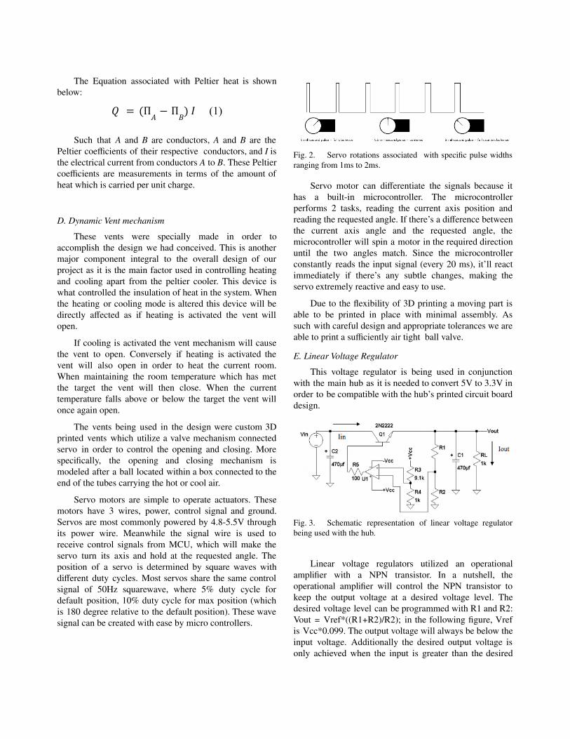
Servo motors are simple to operate actuators. Thesemotors have 3 wires, power, control signal and ground.Servos are most commonly powered by 4.8-5.5V throughits power wire. Meanwhile the signal wire is used toreceive control signals from MCU, which will make theservo turn its axis and hold at the requested angle. Theposition of a servo is determined by square waves withdifferent duty cycles. Most servos share the same controlsignal of 50Hz squarewave, where 5% duty cycle fordefault position, 10% duty cycle for max position (whichis 180 degree relative to the default position). These wavesignal can be created with ease by micro controllers.
Fig. 2. Servo rotations associated with specific pulse widthsranging from 1ms to 2ms.
Servo motor can differentiate the signals because ithas a built-in microcontroller. The microcontrollerperforms 2 tasks, reading the current axis position andreading the requested angle. If there’s a difference betweenthe current axis angle and the requested angle, themicrocontroller will spin a motor in the required directionuntil the two angles match. Since the microcontrollerconstantly reads the input signal (every 20 ms), it’ll reactimmediately if there’s any subtle changes, making theservo extremely reactive and easy to use.
Due to the flexibility of 3D printing a moving part isable to be printed in place with minimal assembly. Assuch with careful design and appropriate tolerances we areable to print a sufficiently air tight ball valve.
E. Linear Voltage Regulator
This voltage regulator is being used in conjunctionwith the main hub as it is needed to convert 5V to 3.3V inorder to be compatible with the hub’s printed circuit boarddesign.
Fig. 3. Schematic representation of linear voltage regulatorbeing used with the hub.
Linear voltage regulators utilized an operationalamplifier with a NPN transistor. In a nutshell, theoperational amplifier will control the NPN transistor tokeep the output voltage at a desired voltage level. Thedesired voltage level can be programmed with R1 and R2:Vout = Vref*((R1+R2)/R2); in the following figure, Vrefis Vcc*0.099. The output voltage will always be below theinput voltage. Additionally the desired output voltage isonly achieved when the input is greater than the desired
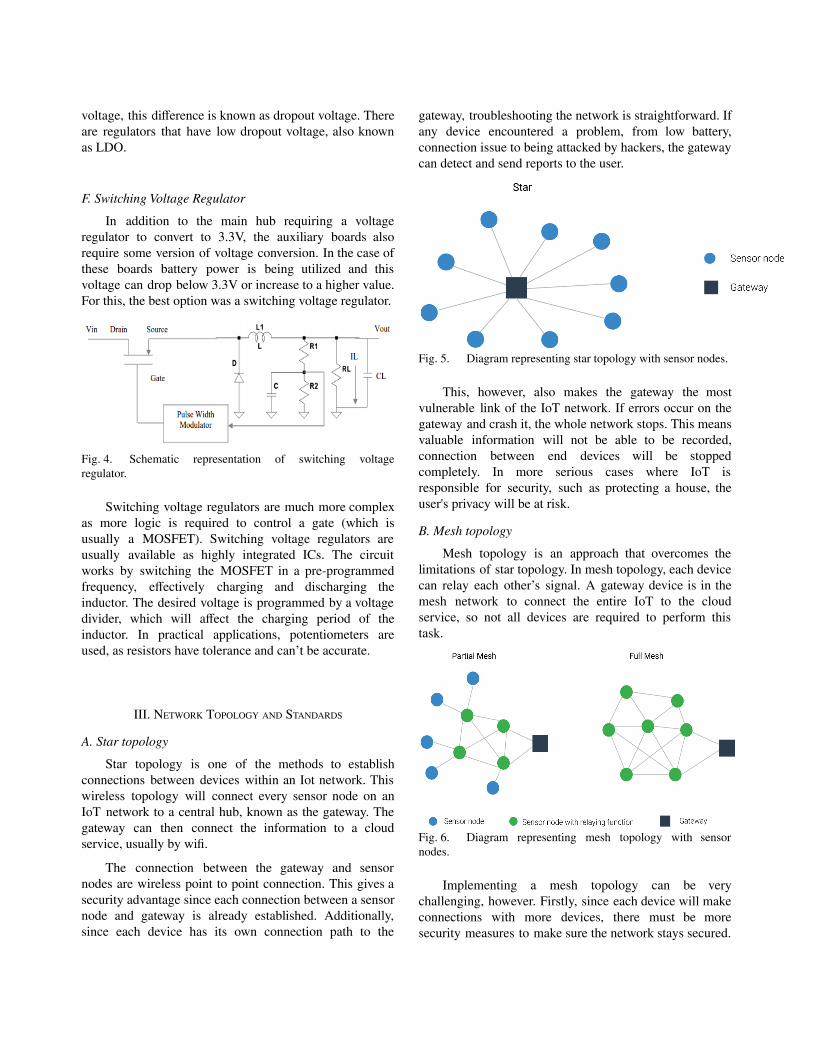
voltage, this difference is known as dropout voltage. Thereare regulators that have low dropout voltage, also knownas LDO.
F. Switching Voltage Regulator
In addition to the main hub requiring a voltageregulator to convert to 3.3V, the auxiliary boards alsorequire some version of voltage conversion. In the case ofthese boards battery power is being utilized and thisvoltage can drop below 3.3V or increase to a higher value.For this, the best option was a switching voltage regulator.
Fig. 4. Schematic representation of switching voltageregulator.
Switching voltage regulators are much more complexas more logic is required to control a gate (which isusually a MOSFET). Switching voltage regulators areusually available as highly integrated ICs. The circuitworks by switching the MOSFET in a pre-programmedfrequency, effectively charging and discharging theinductor. The desired voltage is programmed by a voltagedivider, which will affect the charging period of theinductor. In practical applications, potentiometers areused, as resistors have tolerance and can’t be accurate.
III. NETWORK TOPOLOGY AND STANDARDS
A. Star topology
Star topology is one of the methods to establishconnections between devices within an Iot network. Thiswireless topology will connect every sensor node on anIoT network to a central hub, known as the gateway. Thegateway can then connect the information to a cloudservice, usually by wifi.
The connection between the gateway and sensornodes are wireless point to point connection. This gives asecurity advantage since each connection between a sensornode and gateway is already established. Additionally,since each device has its own connection path to the
gateway, troubleshooting the network is straightforward. Ifany device encountered a problem, from low battery,connection issue to being attacked by hackers, the gatewaycan detect and send reports to the user.
Fig. 5. Diagram representing star topology with sensor nodes.
This, however, also makes the gateway the mostvulnerable link of the IoT network. If errors occur on thegateway and crash it, the whole network stops. This meansvaluable information will not be able to be recorded,connection between end devices will be stoppedcompletely. In more serious cases where IoT isresponsible for security, such as protecting a house, theuser's privacy will be at risk.
B. Mesh topology
Mesh topology is an approach that overcomes thelimitations of star topology. In mesh topology, each devicecan relay each other’s signal. A gateway device is in themesh network to connect the entire IoT to the cloudservice, so not all devices are required to perform thistask.
Fig. 6. Diagram representing mesh topology with sensornodes.
Implementing a mesh topology can be verychallenging, however. Firstly, since each device will makeconnections with more devices, there must be moresecurity measures to make sure the network stays secured.
Secondly, the network might require a lot of relay nodes tocover the entire application area, so implementation can beexpensive. Finally, mesh topology requires each device tohandle data autonomously, so the code can be verycomplex.
C. LoRa
LoRa was the chosen communication standard forour devices. LoRa, which stands for long range, is a lowpower wireless communication protocol developed bySemtech. LoRa operates at sub-gigahertz frequencies of433 MHz to 923 MHz depending on the location orcontinent it is being operated in. LoRa is able to achieve adata transfer rate up to 27 kbps, depending on thespreading factor of the signal.
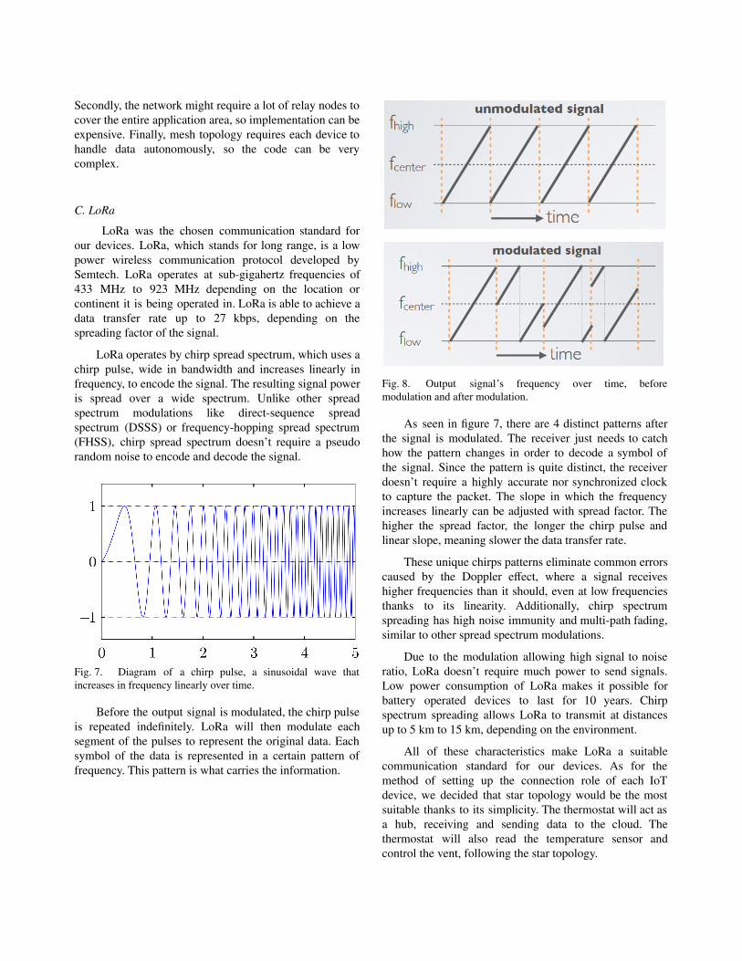
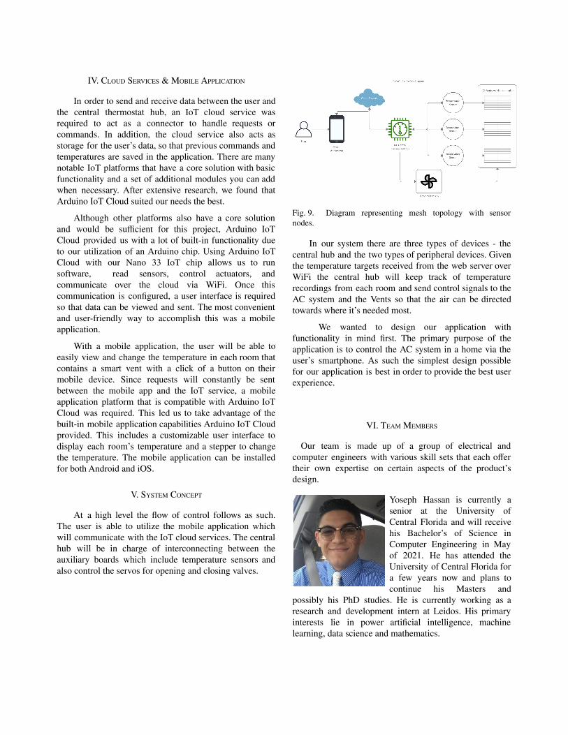
LoRa operates by chirp spread spectrum, which uses achirp pulse, wide in bandwidth and increases linearly infrequency, to encode the signal. The resulting signal poweris spread over a wide spectrum. Unlike other spreadspectrum modulations like direct-sequence spreadspectrum (DSSS) or frequency-hopping spread spectrum(FHSS), chirp spread spectrum doesn’t require a pseudorandom noise to encode and decode the signal.
Fig. 7. Diagram of a chirp pulse, a sinusoidal wave thatincreases in frequency linearly over time.
Before the output signal is modulated, the chirp pulseis repeated indefinitely. LoRa will then modulate eachsegment of the pulses to represent the original data. Eachsymbol of the data is represented in a certain pattern offrequency. This pattern is what carries the information.
Fig. 8. Output signal’s frequency over time, beforemodulation and after modulation.
As seen in figure 7, there are 4 distinct patterns afterthe signal is modulated. The receiver just needs to catchhow the pattern changes in order to decode a symbol ofthe signal. Since the pattern is quite distinct, the receiverdoesn’t require a highly accurate nor synchronized clockto capture the packet. The slope in which the frequencyincreases linearly can be adjusted with spread factor. Thehigher the spread factor, the longer the chirp pulse andlinear slope, meaning slower the data transfer rate.
These unique chirps patterns eliminate common errorscaused by the Doppler effect, where a signal receiveshigher frequencies than it should, even at low frequenciesthanks to its linearity. Additionally, chirp spectrumspreading has high noise immunity and multi-path fading,similar to other spread spectrum modulations.
Due to the modulation allowing high signal to noiseratio, LoRa doesn’t require much power to send signals.Low power consumption of LoRa makes it possible forbattery operated devices to last for 10 years. Chirpspectrum spreading allows LoRa to transmit at distancesup to 5 km to 15 km, depending on the environment.
All of these characteristics make LoRa a suitablecommunication standard for our devices. As for themethod of setting up the connection role of each IoTdevice, we decided that star topology would be the mostsuitable thanks to its simplicity. The thermostat will act asa hub, receiving and sending data to the cloud. Thethermostat will also read the temperature sensor andcontrol the vent, following the star topology.
IV. CLOUD SERVICES & MOBILE APPLICATION
In order to send and receive data between the user andthe central thermostat hub, an IoT cloud service wasrequired to act as a connector to handle requests orcommands. In addition, the cloud service also acts asstorage for the user’s data, so that previous commands andtemperatures are saved in the application. There are manynotable IoT platforms that have a core solution with basicfunctionality and a set of additional modules you can addwhen necessary. After extensive research, we found thatArduino IoT Cloud suited our needs the best.
Although other platforms also have a core solutionand would be sufficient for this project, Arduino IoTCloud provided us with a lot of built-in functionality dueto our utilization of an Arduino chip. Using Arduino IoTCloud with our Nano 33 IoT chip allows us to runsoftware, read sensors, control actuators, andcommunicate over the cloud via WiFi. Once thiscommunication is configured, a user interface is requiredso that data can be viewed and sent. The most convenientand user-friendly way to accomplish this was a mobileapplication.
With a mobile application, the user will be able toeasily view and change the temperature in each room thatcontains a smart vent with a click of a button on theirmobile device. Since requests will constantly be sentbetween the mobile app and the IoT service, a mobileapplication platform that is compatible with Arduino IoTCloud was required. This led us to take advantage of thebuilt-in mobile application capabilities Arduino IoT Cloudprovided. This includes a customizable user interface todisplay each room’s temperature and a stepper to changethe temperature. The mobile application can be installedfor both Android and iOS.
V. SYSTEM CONCEPT
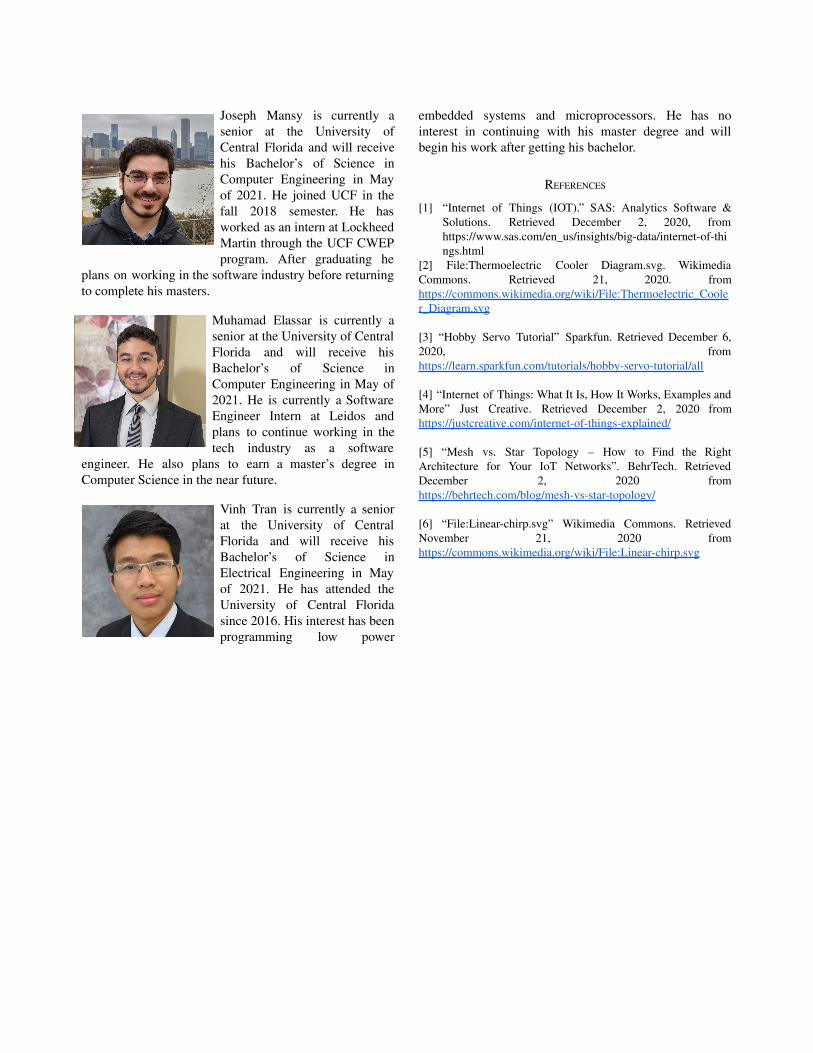
At a high level the flow of control follows as such.The user is able to utilize the mobile application whichwill communicate with the IoT cloud services. The centralhub will be in charge of interconnecting between theauxiliary boards which include temperature sensors andalso control the servos for opening and closing valves.
Fig. 9. Diagram representing mesh topology with sensornodes.
In our system there are three types of devices - thecentral hub and the two types of peripheral devices. Giventhe temperature targets received from the web server overWiFi the central hub will keep track of temperaturerecordings from each room and send control signals to theAC system and the Vents so that the air can be directedtowards where it’s needed most.
We wanted to design our application withfunctionality in mind first. The primary purpose of theapplication is to control the AC system in a home via theuser’s smartphone. As such the simplest design possiblefor our application is best in order to provide the best userexperience.
VI. TEAM MEMBERS
Our team is made up of a group of electrical andcomputer engineers with various skill sets that each offertheir own expertise on certain aspects of the product’sdesign.
Yoseph Hassan is currently asenior at the University ofCentral Florida and will receivehis Bachelor’s of Science inComputer Engineering in Mayof 2021. He has attended theUniversity of Central Florida fora few years now and plans tocontinue his Masters and
possibly his PhD studies. He is currently working as aresearch and development intern at Leidos. His primaryinterests lie in power artificial intelligence, machinelearning, data science and mathematics.
Joseph Mansy is currently asenior at the University ofCentral Florida and will receivehis Bachelor’s of Science inComputer Engineering in Mayof 2021. He joined UCF in thefall 2018 semester. He hasworked as an intern at LockheedMartin through the UCF CWEPprogram. After graduating he
plans on working in the software industry before returningto complete his masters.
Muhamad Elassar is currently asenior at the University of CentralFlorida and will receive hisBachelor’s of Science inComputer Engineering in May of2021. He is currently a SoftwareEngineer Intern at Leidos andplans to continue working in thetech industry as a software
engineer. He also plans to earn a master’s degree inComputer Science in the near future.
Vinh Tran is currently a seniorat the University of CentralFlorida and will receive hisBachelor’s of Science inElectrical Engineering in Mayof 2021. He has attended theUniversity of Central Floridasince 2016. His interest has beenprogramming low power
embedded systems and microprocessors. He has nointerest in continuing with his master degree and willbegin his work after getting his bachelor.
REFERENCES
[1] “Internet of Things (IOT).” SAS: Analytics Software &Solutions. Retrieved December 2, 2020, fromhttps://www.sas.com/en_us/insights/big-data/internet-of-things.html
[2] File:Thermoelectric Cooler Diagram.svg. WikimediaCommons. Retrieved 21, 2020. fromhttps://commons.wikimedia.org/wiki/File:Thermoelectric_Cooler_Diagram.svg
[3] “Hobby Servo Tutorial” Sparkfun. Retrieved December 6,2020, fromhttps://learn.sparkfun.com/tutorials/hobby-servo-tutorial/all
[4] “Internet of Things: What It Is, How It Works, Examples andMore” Just Creative. Retrieved December 2, 2020 fromhttps://justcreative.com/internet-of-things-explained/
[5] “Mesh vs. Star Topology – How to Find the RightArchitecture for Your IoT Networks”. BehrTech. RetrievedDecember 2, 2020 fromhttps://behrtech.com/blog/mesh-vs-star-topology/
[6] “File:Linear-chirp.svg” Wikimedia Commons. RetrievedNovember 21, 2020 fromhttps://commons.wikimedia.org/wiki/File:Linear-chirp.svg
Related Documents


