CAT.8100D CONDUCTIVE POLYMER ALUMINUM SOLID ELECTROLYTIC CAPACITORS CV series Chip Type, High Voltage / Long Life Specifications Temperature Characteristics (Max.Impedance Ratio) Category Temperature Range Rated Voltage Range Rated Capacitance Range Capacitance Tolerance Tangent of loss angle (tan δ) ESR ( 1) Leakage Current ( 2) Performance Characteristics Item – 55 to +105°C 16 to 125V 5.6 to 680µF ± 20% at 120Hz, 20°C Less than or equal to the specified value at 120Hz, 20°C Less than or equal to the specified value at 100kHz, 20°C Less than or equal to the specified value . After 2 minutes' application of rated voltage at 20°C Z+105°C / Z+20°C 1.25 (100kHz) Z– 55°C / Z+20°C 1.25 Endurance Damp Heat (Steady State) Resistance to Soldering Heat Marking The specifications listed at right shall be met when the capacitors are restored to 20°C after the rated voltage is applied for 3000 hours at 105°C. The specifications listed at right shall be met when the capacitors are restored to 20°C after the rated voltage is applied for 1000 hours at 60°C, 90% RH. After soldering the capacitor under the soldering conditions prescribed here, the capacitor shall meet the specifications listed at right, provided that it's temperature profile is measured at the capacitor top and the terminal. Pre-heating shall be done at 150 to 200°C and for 60 to 180 sec. The duration for over +230°C temperature at capacitor surface shall not exceed 60 seconds. In the case of peak temp, less than 250°C, reflow soldering shall be two times maximum. In the case of peak temp, less than 260°C, reflow soldering shall be once. Measurement for solder temperature profile shall be made at the capacitor top and the terminal. Navy blue print on the case top Capacitance change tan δ Leakage current ( 2) ESR ( 1) Within ± 20% of the initial capacitance value ( 3) 150% or less than the initial specified value 150% or less than the initial specified value Less than or equal to the initial specified value Capacitance change tan δ Leakage current ( 2) ESR ( 1) Within ± 20% of the initial capacitance value ( 3) 150% or less than the initial specified value 150% or less than the initial specified value Less than or equal to the initial specified value Capacitance change tan δ Leakage current ( 2) ESR ( 1) Within ± 10% of the initial capacitance value ( 3) 130% or less than the initial specified value 130% or less than the initial specified value Less than or equal to the initial specified value High voltage (to 125V), Low ESR, High ripple current. Load life of 3000 hours at 105°C. SMD type : Lead free reflow soldering condition at 260°C peak correspondence. Compliant to the RoHS directive (2011/65/EU). 1 ESR should be measured at both of the terminal ends closest where the terminals protrude through the plastic platform. 2 Conditioning : If any doubt arises, measure the leakage current after the voltage treatment of applying DC rated voltage continuously to the capacitor for 120 minutes at 105°C. 3 Initial value : The value before test of examination of resistance to soldering. P 1 C 2 V 3 1 4 V 5 8 6 2 7 0 8 M 9 C 10 L 11 1 12 G 13 S 14 Configuration Taping code Size code Capacitance tolerance (±20%) Rated capacitance (82μF) Rated voltage (35V) Series name Type CV 82 V 012 H 0.3 MAX. φD±0.5 B±0.2 A±0.2 C±0.2 0.5 MAX. E L Series Voltage (V:35V) Plastic platform Lot No. Capacitance Negative Positive +0.1 -0.4 Dimensions Type numbering system (Example : 35V 82µF) Dimension table in next page. φD L A B C E H 6.3 5.9 7.3 6.6 6.6 2.1 0.5 to 0.8 Size φ6.3 ×6L 8.0 6.9 9.0 8.3 8.3 3.2 0.8 to 1.1 φ8 ×7L 8.0 9.9 9.0 8.3 8.3 3.2 0.8 to 1.1 φ8 ×10L 8.0 11.9 9.0 8.3 8.3 3.2 0.8 to 1.1 φ8 ×12L 10.0 7.9 11.0 10.3 10.3 4.6 0.8 to 1.1 φ10 ×8L 10.0 9.9 11.0 10.3 10.3 4.6 0.8 to 1.1 φ10 ×10L 10.0 12.6 11.0 10.3 10.3 4.6 0.8 to 1.1 φ10 ×12.7L (mm) Code C V 16 D 20 E 25 V 35 H 50 J 63 K 80 2A 100 2B 125 Voltage CV High Temperature CX

Welcome message from author
This document is posted to help you gain knowledge. Please leave a comment to let me know what you think about it! Share it to your friends and learn new things together.
Transcript
CAT.8100D
CONDUCTIVE POLYMER ALUMINUM SOLID ELECTROLYTIC CAPACITORS
CVseries
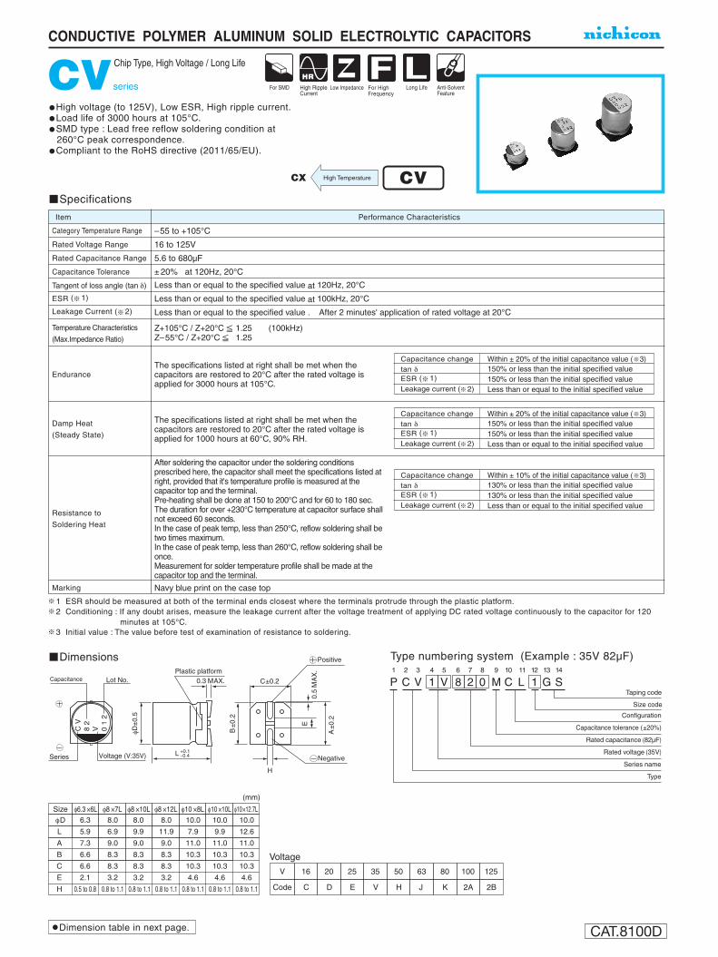
Chip Type, High Voltage / Long Life
Specifications
Temperature Characteristics
(Max.Impedance Ratio)
Category Temperature Range
Rated Voltage Range
Rated Capacitance Range
Capacitance Tolerance
Tangent of loss angle (tan δ)
ESR ( 1)
Leakage Current ( 2)
Performance CharacteristicsItem
–55 to +105°C
16 to 125V
5.6 to 680µF
± 20% at 120Hz, 20°C
Less than or equal to the specified value at 120Hz, 20°C
Less than or equal to the specified value at 100kHz, 20°C
Less than or equal to the specified value . After 2 minutes' application of rated voltage at 20°C
Z+105°C / Z+20°C 1.25 (100kHz)Z–55°C / Z+20°C 1.25
Endurance
Damp Heat
(Steady State)
Resistance to
Soldering Heat
Marking
The specifications listed at right shall be met when the capacitors are restored to 20°C after the rated voltage is applied for 3000 hours at 105°C.
The specifications listed at right shall be met when the capacitors are restored to 20°C after the rated voltage is applied for 1000 hours at 60°C, 90% RH.
After soldering the capacitor under the soldering conditions prescribed here, the capacitor shall meet the specifications listed at right, provided that it's temperature profile is measured at the capacitor top and the terminal.Pre-heating shall be done at 150 to 200°C and for 60 to 180 sec.The duration for over +230°C temperature at capacitor surface shall not exceed 60 seconds.In the case of peak temp, less than 250°C, reflow soldering shall be two times maximum.In the case of peak temp, less than 260°C, reflow soldering shall be once.Measurement for solder temperature profile shall be made at the capacitor top and the terminal.
Navy blue print on the case top
Capacitance changetan δ
Leakage current ( 2)ESR ( 1)
Within ± 20% of the initial capacitance value ( 3)150% or less than the initial specified value150% or less than the initial specified valueLess than or equal to the initial specified value
Capacitance changetan δ
Leakage current ( 2)ESR ( 1)
Within ± 20% of the initial capacitance value ( 3)150% or less than the initial specified value150% or less than the initial specified valueLess than or equal to the initial specified value
Capacitance changetan δ
Leakage current ( 2)ESR ( 1)
Within ± 10% of the initial capacitance value ( 3)130% or less than the initial specified value130% or less than the initial specified valueLess than or equal to the initial specified value
High voltage (to 125V), Low ESR, High ripple current.Load life of 3000 hours at 105°C.SMD type : Lead free reflow soldering condition at
260°C peak correspondence.Compliant to the RoHS directive (2011/65/EU).
1 ESR should be measured at both of the terminal ends closest where the terminals protrude through the plastic platform.2 Conditioning : If any doubt arises, measure the leakage current after the voltage treatment of applying DC rated voltage continuously to the capacitor for 120
minutes at 105°C.3 Initial value : The value before test of examination of resistance to soldering.
P1
C2
V3
14
V5
86
27
08
M9
C10
L11
112
G13
S14
Configuration
Taping code
Size code
Capacitance tolerance (±20%)
Rated capacitance (82µF)
Rated voltage (35V)
Series name
Type
CV
82
V 01
2
H
0.3 MAX.
φD±
0.5
B±
0.2
A±
0.2
C±0.2
0.5
MA
X.
E
LSeries Voltage (V:35V)
Plastic platformLot No.Capacitance
Negative
Positive
+0.1-0.4
Dimensions Type numbering system (Example : 35V 82µF)
Dimension table in next page.
φD
L
A
B
C
E
H
6.3
5.9
7.3
6.6
6.6
2.1
0.5 to 0.8
Size φ6.3 ×6L8.0
6.9
9.0
8.3
8.3
3.2
0.8 to 1.1
φ8 ×7L8.0
9.9
9.0
8.3
8.3
3.2
0.8 to 1.1
φ8 ×10L8.0
11.9
9.0
8.3
8.3
3.2
0.8 to 1.1
φ8 ×12L10.0
7.9
11.0
10.3
10.3
4.6
0.8 to 1.1
φ10 ×8L10.0
9.9
11.0
10.3
10.3
4.6
0.8 to 1.1
φ10 ×10L10.0
12.6
11.0
10.3
10.3
4.6
0.8 to 1.1
φ10×12.7L
(mm)
Code C
V 16
D
20
E
25
V
35
H
50
J
63
K
80
2A
100
2B
125
Voltage
CVHigh TemperatureCX

CAT.8100D
CONDUCTIVE POLYMER ALUMINUM SOLID ELECTROLYTIC CAPACITORS
CVseries
Standard Ratings
Rated Voltage(V)(code)
Surge Voltage (V)
ESR (mΩ)(at 100kHz 20°C)
Rated Ripple(mArms)
Rated Capacitance(µF)
Case SizeφD × L (mm) tan δ Part Number
Leakage Current(µA)
1000
1300
1500
1700
2000
2000
3800
2300
3200
2400
4100
3900
2800
4400
1000
1300
1300
1400
2000
1900
3100
3700
2300
4000
2300
3800
2700
4300
1000
1300
1300
1400
1900
1800
3600
2200
3000
2300
3800
3700
2700
4200
900
1300
1200
1400
1900
1800
3600
2200
3000
2200
3800
3700
2600
4100
50
47
36
34
27
31
21
26
24
26
20
21
25
19
55
48
45
42
28
33
25
22
27
21
27
22
26
20
60
49
50
47
29
35
23
28
26
28
22
23
27
21
64
50
55
52
31
37
24
29
27
29
23
24
28
22
179
262
320
480
704
704
864
864
864
1056
1248
1504
1504
2176
188
224
272
400
600
600
720
880
880
1080
1080
1320
1320
1880
165
235
280
410
600
600
750
750
750
900
1100
1350
1350
1950
126
154
189
273
392
476
574
574
574
700
840
840
1050
1260
0.12
0.12
0.12
0.12
0.12
0.12
0.12
0.12
0.12
0.12
0.12
0.12
0.12
0.12
0.12
0.12
0.12
0.12
0.12
0.12
0.12
0.12
0.12
0.12
0.12
0.12
0.12
0.12
0.12
0.12
0.12
0.12
0.12
0.12
0.12
0.12
0.12
0.12
0.12
0.12
0.12
0.12
0.12
0.12
0.12
0.12
0.12
0.12
0.12
0.12
0.12
0.12
0.12
0.12
0.12
0.12
6.3 × 6
6.3 × 6
8 × 7
8 × 7
8 × 10
10 × 8
8 × 10
8 × 12
10 × 8
10 × 10
8 × 12
10 × 10
10 × 12.7
10 × 12.7
6.3 × 6
6.3 × 6
8 × 7
8 × 7
8 × 10
10 × 8
10 × 8
8 × 10
8 × 12
8 × 12
10 × 10
10 × 10
10 × 12.7
10 × 12.7
6.3 × 6
6.3 × 6
8 × 7
8 × 7
8 × 10
10 × 8
8 × 10
8 × 12
10 × 8
10 × 10
8 × 12
10 × 10
10 × 12.7
10 × 12.7
6.3 × 6
6.3 × 6
8 × 7
8 × 7
8 × 10
10 × 8
8 × 10
8 × 12
10 × 8
10 × 10
8 × 12
10 × 10
10 × 12.7
10 × 12.7
56
82
100
150
220
220
270
270
270
330
390
470
470
680
47
56
68
100
150
150
180
220
220
270
270
330
330
470
33
47
56
82
120
120
150
150
150
180
220
270
270
390
18
22
27
39
56
68
82
82
82
100
120
120
150
180
18.4
28.7
23.0
16(1C)
20(1D)
25(1E)
PCV1C560MCL1GS
PCV1C820MCL2GS
PCV1C101MCL1GS
PCV1C151MCL2GS
PCV1C221MCL6GS
PCV1C221MCL1GS
PCV1C271MCL7GS
PCV1C271MCL1GS
PCV1C271MCL2GS
PCV1C331MCL1GS
PCV1C391MCL2GS
PCV1C471MCL2GS
PCV1C471MCL1GS
PCV1C681MCL2GS
PCV1D470MCL1GS
PCV1D560MCL2GS
PCV1D680MCL1GS
PCV1D101MCL2GS
PCV1D151MCL6GS
PCV1D151MCL1GS
PCV1D181MCL2GS
PCV1D221MCL7GS
PCV1D221MCL1GS
PCV1D271MCL2GS
PCV1D271MCL1GS
PCV1D331MCL2GS
PCV1D331MCL1GS
PCV1D471MCL2GS
PCV1E330MCL1GS
PCV1E470MCL2GS
PCV1E560MCL1GS
PCV1E820MCL2GS
PCV1E121MCL6GS
PCV1E121MCL1GS
PCV1E151MCL7GS
PCV1E151MCL1GS
PCV1E151MCL2GS
PCV1E181MCL1GS
PCV1E221MCL2GS
PCV1E271MCL2GS
PCV1E271MCL1GS
PCV1E391MCL2GS
PCV1V180MCL1GS
PCV1V220MCL2GS
PCV1V270MCL1GS
PCV1V390MCL2GS
PCV1V560MCL1GS
PCV1V680MCL1GS
PCV1V820MCL7GS
PCV1V820MCL1GS
PCV1V820MCL2GS
PCV1V101MCL1GS
PCV1V121MCL7GS
PCV1V121MCL2GS
PCV1V151MCL1GS
PCV1V181MCL2GS
40.235(1V)

CAT.8100D
CONDUCTIVE POLYMER ALUMINUM SOLID ELECTROLYTIC CAPACITORS
CVseries
Standard Ratings
Taping specifications are given in page 23. Recommended land size, soldering by reflow are given in page 18, 19. Please refer to page 3 for the minimum order quantity.
Rated Voltage(V)(code)
Surge Voltage (V)
ESR (mΩ)(at 100kHz 20°C)
Rated Ripple(mArms)
Rated Capacitance(µF)
Case SizeφD × L (mm) tan δ Part Number
Leakage Current(µA)
800
1200
1100
1300
1700
1500
2000
3300
2600
2200
3400
3400
2600
3600
700
1200
1000
1100
1700
1400
3200
2000
2500
2200
3400
3300
2500
3400
1600
1800
1900
2200
1500
1700
1900
2100
1100
1300
1400
2000
81
55
63
60
36
49
34
29
37
30
28
29
29
27
105
56
75
70
37
56
30
35
38
31
29
30
30
28
43
41
39
38
48
45
42
41
93
84
69
48
82
120
150
220
330
330
390
470
470
470
560
680
680
1000
71
103
126
151
277
277
340
340
340
416
491
592
592
706
160
192
240
352
136
200
240
360
170
205
300
375
0.12
0.12
0.12
0.12
0.12
0.12
0.12
0.12
0.12
0.12
0.12
0.12
0.12
0.12
0.12
0.12
0.12
0.12
0.12
0.12
0.12
0.12
0.12
0.12
0.12
0.12
0.12
0.12
0.12
0.12
0.12
0.12
0.12
0.12
0.12
0.12
0.12
0.12
0.12
0.12
6.3 ×6
6.3 × 6
8 × 7
8 × 7
8 × 10
10 × 8
8 × 12
8 × 10
10 × 8
10 × 10
8 × 12
10 × 10
10 × 12.7
10 × 12.7
6.3 × 6
6.3 × 6
8 × 7
8 × 7
8 × 10
10 × 8
8 × 10
8 × 12
10 × 8
10 × 10
8 × 12
10 × 10
10 × 12.7
10 × 12.7
8 × 10
8 × 12
10 × 10
10 × 12.7
8 × 10
8 × 12
10 × 10
10 × 12.7
8 × 10
8 × 12
10 × 10
10 × 12.7
8.2
12
15
22
33
33
39
47
47
47
56
68
68
100
5.6
8.2
10
12
22
22
27
27
27
33
39
47
47
56
10
12
15
22
10
12
18
12
15
57.5
72.4
92.0
50(1H)
63(1J)
80(1K)
115100(2A)
143125(2B)
PCV1H8R2MCL1GS
PCV1H120MCL2GS
PCV1H150MCL1GS
PCV1H220MCL2GS
PCV1H330MCL6GS
PCV1H330MCL1GS
PCV1H390MCL1GS
PCV1H470MCL7GS
PCV1H470MCL2GS
PCV1H470MCL1GS
PCV1H560MCL2GS
PCV1H680MCL2GS
PCV1H680MCL1GS
PCV1H101MCL2GS
PCV1J5R6MCL1GS
PCV1J8R2MCL2GS
PCV1J100MCL1GS
PCV1J120MCL2GS
PCV1J220MCL6GS
PCV1J220MCL1GS
PCV1J270MCL7GS
PCV1J270MCL1GS
PCV1J270MCL2GS
PCV1J330MCL1GS
PCV1J390MCL2GS
PCV1J470MCL2GS
PCV1J470MCL1GS
PCV1J560MCL2GS
PCV1K100MCL1GS
PCV1K120MCL1GS
PCV1K150MCL1GS
PCV1K220MCL1GS
PCV2A6R8MCL1GS
PCV2A100MCL1GS
PCV2A120MCL1GS
PCV2A180MCL1GS
PCV2B6R8MCL1GS
PCV2B8R2MCL1GS
PCV2B120MCL1GS
PCV2B150MCL1GS
6.8
6.8
8.2
Rated ripple current (mArms) at 105°C 100kHz No marked, 1 will be put at 12th digit of type numbering system.
: In this case, 2 will be put at 12th digit of type numbering system.: In this case, 6 will be put at 12th digit of type numbering system.: In this case, 7 will be put at 12th digit of type numbering system.
Related Documents