Conduction Mechanisms of Chloride Ions in ClC-Type Channels Ben Corry, Megan O’Mara, and Shin-Ho Chung Department of Theoretical Physics, Research School of Physical Sciences, The Australian National University, Canberra, Australia ABSTRACT The conduction properties of ClC-0 and ClC-1 chloride channels are examined using electrostatic calculations and three-dimensional Brownian dynamics simulations. We create an open-state configuration of the prokaryotic ClC Cl ÿ channel using its known crystallographic structure as a basis. Two residues that are occluding the channel are slowly pushed outward with molecular dynamics to create a continuous ion-conducting path with the minimum radius of 2.5 A ˚ . Then, retaining the same pore shape, the prokaryotic ClC channel is converted to either ClC-0 or ClC-1 by replacing all the nonconserved dipole-containing and charged amino acid residues. Employing open-state ClC-0 and ClC-1 channel models, current-voltage curves consistent with experimental measurements are obtained. We find that conduction in these pores involves three ions. We locate the binding sites, as well as pinpointing the rate-limiting steps in conduction, and make testable predictions about how the single channel current across ClC-0 and ClC-1 will vary as the ionic concentrations are increased. Finally, we demonstrate that a ClC-0 homology model created from an alternative sequence alignment fails to replicate any of the experimental observations. INTRODUCTION Anionic channels are essential in maintaining the integrity of synaptic physiology and perform a diverse range of physiological functions, yet they have been largely neglected in theoretical investigations. Here we focus our attention on a subclass of channels that are selectively permeable to anions: the voltage-gated ClC family of chloride channels, present in the cell membranes of every living organism. ClC Cl ÿ channels perform diverse roles, such as the control of cellular excitability, acidification of intracellular vesicles, and cell volume regulation (see, for recent reviews, Jentsch et al., 1999, 2002; Maduke et al., 2000; Fahlke, 2001). The prototype channel ClC-0, from the Torpedo electroplax, was first discovered and characterized by Miller (1982). Since then, nine ClC channel isoforms have been identified in humans alone, each with a slightly different tissue dis- tribution, but the precise physiological role of several of these isoforms remains unknown. The biggest clue in de- termining the primary role of each isoform is obtained by examining the diseases induced by ClC channel muta- tions. Genetic mutations of ClC channels are known to be associated with myotonia congenita, a muscle disease charac- terized by stiffness on sudden movement (ClC-1); Dent’s disease, an inherited kidney disorder (ClC-5); and Bartter’s syndrome, a salt-wasting renal tubular disorder (ClC-K). It will be a challenge to uncover how and why mutations of these genes alter the permeation dynamics of Cl ÿ ions. Over the past decade, many salient properties of ClC-type channels have been uncovered using the techniques of molecular cloning and subsequent heterologous expression (Jentsch et al., 1990). First among these properties is the fast gating mechanism. ClC channels undergo voltage-dependent transitions between open and closed states (Pusch et al., 1995; Chen and Miller, 1996; Rychkov et al., 2001), which are facilitated by Cl ÿ ions in the extracellular solutions. Thus, unlike the cationic voltage-gated channels, a permeat- ing Cl ÿ ion itself appears to be acting as a ligand. Secondly, conduction properties differ among the isoforms. The current-voltage relationships measured from ClC-0 and ClC-2 are linear (Miller, 1982; Lorenz et al., 1996), whereas those measured from other isoforms are either inwardly rectifying (ClC-1; Rychkov et al., 2001) or outwardly rectifying (ClC-3, ClC-4, and ClC-5; Duan et al., 1999; Kawasaki et al., 1995; Steinmeyer et al., 1995; Friedrich et al., 1999; Vonoye and George, 2002). Thirdly, ClC-0, and perhaps other ClC-type channels, show an anomalous mole fraction behavior in a mixed solution of Cl ÿ and NO 3 ions (Pusch et al., 1995), thus suggesting that conduction across the pore is a multi-ion process. Because the conductance of all ClC-type channels is low, ranging from 10 pS to \ 1 pS, detailed characterizations of single channel properties have not yet been carried out. Despite the availability of x-ray structures of two prokaryotic ClC Cl ÿ channels and their mutations (Dutzler et al., 2002, 2003), as yet there has been no theoretical study that attempts to relate the atomic structure of a ClC channel to the macroscopic properties. One of the difficulties in utilizing the newly unveiled information is that all of the published crystallographic structures, including the E148A mutant channel in the postulated open state, have atoms occluding the pore and obstructing Cl ÿ permeation. In the wild-type E. coli ClC (EcClC) channel structure, residues from the N-termini of the D, F, and N a-helices are constricting the channel and two of these residues are completely blocking the conduction pore. As we follow the EcClC pore from either the extracellular or intracellular Submitted November 27, 2003, and accepted for publication December 15, 2003. Address reprint requests to Shin-Ho Chung, The Australian National Uni- versity, Research School of Physical Sciences, Dept. of Theoretical Physics, Canberra, ACT 0200, Australia. Tel.: 61-2-6125-2024; Fax: 61-2-6247- 2792; E-mail: [email protected]. Ó 2004 by the Biophysical Society 0006-3495/04/02/846/15 $2.00 846 Biophysical Journal Volume 86 February 2004 846–860

Welcome message from author
This document is posted to help you gain knowledge. Please leave a comment to let me know what you think about it! Share it to your friends and learn new things together.
Transcript

Conduction Mechanisms of Chloride Ions in ClC-Type Channels
Ben Corry, Megan O’Mara, and Shin-Ho ChungDepartment of Theoretical Physics, Research School of Physical Sciences, The Australian National University, Canberra, Australia
ABSTRACT The conduction properties of ClC-0 and ClC-1 chloride channels are examined using electrostatic calculationsand three-dimensional Brownian dynamics simulations. We create an open-state configuration of the prokaryotic ClC Cl�
channel using its known crystallographic structure as a basis. Two residues that are occluding the channel are slowly pushedoutward with molecular dynamics to create a continuous ion-conducting path with the minimum radius of 2.5 A. Then, retainingthe same pore shape, the prokaryotic ClC channel is converted to either ClC-0 or ClC-1 by replacing all the nonconserveddipole-containing and charged amino acid residues. Employing open-state ClC-0 and ClC-1 channel models, current-voltagecurves consistent with experimental measurements are obtained. We find that conduction in these pores involves three ions.We locate the binding sites, as well as pinpointing the rate-limiting steps in conduction, and make testable predictions abouthow the single channel current across ClC-0 and ClC-1 will vary as the ionic concentrations are increased. Finally, wedemonstrate that a ClC-0 homology model created from an alternative sequence alignment fails to replicate any of theexperimental observations.
INTRODUCTION
Anionic channels are essential in maintaining the integrity
of synaptic physiology and perform a diverse range of
physiological functions, yet they have been largely neglected
in theoretical investigations. Here we focus our attention on
a subclass of channels that are selectively permeable to
anions: the voltage-gated ClC family of chloride channels,
present in the cell membranes of every living organism. ClC
Cl� channels perform diverse roles, such as the control of
cellular excitability, acidification of intracellular vesicles,
and cell volume regulation (see, for recent reviews, Jentsch
et al., 1999, 2002; Maduke et al., 2000; Fahlke, 2001). The
prototype channel ClC-0, from the Torpedo electroplax, wasfirst discovered and characterized by Miller (1982). Since
then, nine ClC channel isoforms have been identified in
humans alone, each with a slightly different tissue dis-
tribution, but the precise physiological role of several of
these isoforms remains unknown. The biggest clue in de-
termining the primary role of each isoform is obtained by
examining the diseases induced by ClC channel muta-
tions. Genetic mutations of ClC channels are known to be
associated with myotonia congenita, a muscle disease charac-
terized by stiffness on sudden movement (ClC-1); Dent’s
disease, an inherited kidney disorder (ClC-5); and Bartter’s
syndrome, a salt-wasting renal tubular disorder (ClC-K). It
will be a challenge to uncover how and why mutations of
these genes alter the permeation dynamics of Cl� ions.
Over the past decade, many salient properties of ClC-type
channels have been uncovered using the techniques of
molecular cloning and subsequent heterologous expression
(Jentsch et al., 1990). First among these properties is the fast
gating mechanism. ClC channels undergo voltage-dependent
transitions between open and closed states (Pusch et al.,
1995; Chen and Miller, 1996; Rychkov et al., 2001), which
are facilitated by Cl� ions in the extracellular solutions.
Thus, unlike the cationic voltage-gated channels, a permeat-
ing Cl� ion itself appears to be acting as a ligand. Secondly,
conduction properties differ among the isoforms. The
current-voltage relationships measured from ClC-0 and
ClC-2 are linear (Miller, 1982; Lorenz et al., 1996), whereas
those measured from other isoforms are either inwardly
rectifying (ClC-1; Rychkov et al., 2001) or outwardly
rectifying (ClC-3, ClC-4, and ClC-5; Duan et al., 1999;
Kawasaki et al., 1995; Steinmeyer et al., 1995; Friedrich
et al., 1999; Vonoye and George, 2002). Thirdly, ClC-0, and
perhaps other ClC-type channels, show an anomalous mole
fraction behavior in a mixed solution of Cl� and NO3 ions
(Pusch et al., 1995), thus suggesting that conduction across
the pore is a multi-ion process. Because the conductance of
all ClC-type channels is low, ranging from 10 pS to\1 pS,
detailed characterizations of single channel properties have
not yet been carried out.
Despite the availability of x-ray structures of two
prokaryotic ClC Cl� channels and their mutations (Dutzler
et al., 2002, 2003), as yet there has been no theoretical study
that attempts to relate the atomic structure of a ClC channel
to the macroscopic properties. One of the difficulties in
utilizing the newly unveiled information is that all of the
published crystallographic structures, including the E148A
mutant channel in the postulated open state, have atoms
occluding the pore and obstructing Cl� permeation. In the
wild-type E. coli ClC (EcClC) channel structure, residues
from the N-termini of the D, F, and N a-helices are
constricting the channel and two of these residues are
completely blocking the conduction pore. As we follow the
EcClC pore from either the extracellular or intracellular
Submitted November 27, 2003, and accepted for publication December 15,
2003.
Address reprint requests to Shin-Ho Chung, The Australian National Uni-
versity, Research School of Physical Sciences, Dept. of Theoretical Physics,
Canberra, ACT 0200, Australia. Tel.: 61-2-6125-2024; Fax: 61-2-6247-
2792; E-mail: [email protected].
� 2004 by the Biophysical Society
0006-3495/04/02/846/15 $2.00
846 Biophysical Journal Volume 86 February 2004 846–860

opening toward the middle of the pore, it abruptly tapers and
vanishes. Investigation of the postulated open state configu-
ration of the E. coli E148A mutant reveals that two residues
are still partially occluding the channel, preventing Cl�
permeation. It is likely that the conduction path of ions
in these channels has become distorted in the process of
crystallization or that they represent the channel in a closed
state. Thus, before the crystal structure coordinates can be
used to investigate the permeation of ions through the
channel, a completely open state structure needs to be
created by using molecular dynamics or other means.
Moreover, the ion-conducting path of the EcClC channel,
unlike that of the KcsA channel (Doyle et al., 1998), takes
a tortuous course through the protein, instead of being
straight and perpendicular to the plane of the membrane. The
meandering nature of the ClC pore complicates calculations
of the force an ion experiences as it moves through the pore.
Here we examine the dynamics of ion permeation in ClC-
0 and ClC-1, the two most thoroughly studied ClC chan-
nels, using electrostatic calculations and three-dimensional
Brownian dynamics simulations. We first build an open
state configuration of the channel with molecular dynam-
ics simulations, by pushing the pore-lining residues located
near the middle of the channel outward until the segment
attains the desired interior radius of �2.5 A, the smallest
radius that allows conduction of both Cl� and NO3�. Then,
we convert the bacterial EcClC channel into ClC-0 and ClC-
1 by replacing all the charged and dipole-containing amino
acid residues that are not conserved. Utilizing the full atomic
models of the channels so constructed, we carry out elec-
trostatic calculations and Brownian dynamics simulations
to elucidate the permeation dynamics across the pores and in-
vestigate the effect of several point mutations.
METHODS
Building open-state models of ClC-0 and ClC-1
Although the ClC protein is a homodimer, forming two identical pores
(Middleton et al., 1996; Ludewig et al., 1996), we simplify our model by
dealing with only one of the two pores throughout this study. In Fig. 1 A, we
show a view of the pore from the plane of the membrane, created from the
crystallographic protein structure of the Escherichia coli ClC channel
(EcClC) reported by Dutzler et al. (2002) (Protein Data Bank accession code
1KPK). Despite the slightly higher resolution of the E148A crystal structure
(Dutzler et al., 2003), we choose the wild-type EcClC as our template for this
study, due to the presence of the key gating residue Glu-148 in its native
state. Later we demonstrate that the results we obtain with the model based
on the low-resolution x-ray structure do not differ from those obtained with
the model based on the high-resolution structure. To reveal the ion-
conducting path, the front half of the protein is removed in the figure. There
is no continuous course which ions can traverse from the intracellular to
extracellular sides of the protein, as shown in Fig. 1 A. There are deep
depressions on each side of the protein, but atoms from two of the central
residues in the EcClC structure, Ser-107 and Glu-148, occlude the pore.
Although the pathway to the external vestibule can be deduced from the
wild-type structure, the task of locating the ion-conducting pathway is
simplified by overlaying the E148A postulated open structure. Here, three
Cl� ions sit in between the channel entrances, two of which are trapped in
the protein between the intracellular and extracellular depressions by Ser-
107 and Lys-147, suggesting that the two depressions join to form
a conducting conduit for Cl� ions. Although the width of the pathway is not
large enough to allow a Cl� to pass, the likely location of the pore axis can
be determined.
For a Cl� to navigate across either the wild-type or the E148A EcClC
channel, the blocking residues must move sideways so as to create a pore
with radius[1.81 A, that of a chloride ion. To allow conduction of larger
ionic species, such as I� and NO3�, and reproduction of other experimental
results, the minimum pore radius must be increased closer to 2.5 A. We
create an open state shape in as simple a way as possible, by gently pushing
the occluding residues outward and allowing them to find their own
orientation.
Expansion of the EcClC channel, using the x-ray structure reported by
Dutzler et al. (2002), to an open state is carried out with CHARMM (Brooks
et al., 1983), utilizing Version 19 extended-atom parameters for protein.
Atoms blocking the pore are pushed aside using a CHARMM MMFP
cylindrical repulsive force. Because the region where the pore is blocked is
curved, six short MMFP cylinders are placed along the channel center line,
with each cylinder axis aligned tangential to the axis of the pore. Since the
surrounding atoms have radii of ;1.5 A, the radius of the MMFP cylinders
(measured to the atom centers) is set to 5 A. By placing these cylinders,
starting from z ¼ �12.5 A, to follow the curvature of the pore, all the atoms
protruding into the pore can be contained within their interiors. Any atoms
FIGURE 1 The shape of the model channel and Brownian dynamics
simulation system. The atomic detail of the crystal structure of the E. colichannel, EcClC, taken from Dutzler et al. (2002) (A) and our open model of
the channel (inset) are shown with the front half of the atoms removed to
reveal the pore. The surface of the open pore in gold is superimposed on each
diagram. (B) A cylindrical reservoir containing a fixed number of Na1
(shown in yellow) and Cl� (green) is attached at each end of the channel for
Brownian dynamics simulation. The channel protein is imbedded in a low
dielectric region representing the membrane (gold ).
Conduction in CIC Channels 847
Biophysical Journal 86(2) 846–860

inside the cylinders are then pushed outward with harmonic force of 85 kT/
A2 (or 50 kcal/mol/A2) relative to the surface. All atoms outside the
cylinders are held near their initial positions using comparatively weak
harmonic constraints of 1.6 kT/A2. The expansion is carried out in two
stages of 500 steps of CHARMM dynamics at 298 K, with the final atom
positions from the first stage used as new initial positions for constraints
during the second stage.
The open structure of the pore thus created is shown in the inset of Fig.
1 A. The shape of the open pore surface used for our calculations is indicated
by the gold-colored surface superimposed on the closed and open structures.
The ClC pore takes a tortuous course through the protein, unlike the KcsA
potassium channel, which is straight and lies perpendicular to the plane of
the membrane. We have imposed the condition that the cross-section of the
channel perpendicular to the channel axis must be circular, to simplify the
computational steps involved in determining and storing the electric field
inside the pore. The channel remains quite narrow, having a minimum radius
of r� 2.5 A near the center, but opens up quite rapidly at each end. Notably, the
orientation of the Glu-148 residue is similar to that seen in the E148Amutant.
We make an assumption that the overall shape of the open-state pore for
EcClC that we created is approximately the same as for ClC-0 and ClC-1.
Thus, we hypothesize that it is the differing amino acid sequence that yields
the different conductance properties of these channel isoforms. This is
a plausible assumption and is supported by a recent study that examines the
location of inhibitor binding sites to suggest a high degree of structural
similarity between bacterial and mammalian ClC channels (Estevez et al.,
2003).
Next we convert the open-state bacterial ClC channel into ClC-0 and
ClC-1 using primarily the sequence alignment of Dutzler et al. (2002). There
is a limited sequence similarity between the bacterial and prokaryotic
homologs, and the alignment in many regions is dubious. For example, the
residue population between the various domains in ClC-0 is far denser than
in the bacterial channel. Thus, for ClC-0, we also generated two additional
sequence alignments using ClustalW (Thompson et al., 1994), one without
and the other one with manual adjustment. To generate a sequence alignment
between ClC-0 and EcClC, we use the ClC-0 amino acid sequence from
Torpedo california (Genebank number: P35522). To overcome the large
difference in the length of the sequence, we crop the nonaligned C-terminus
residues of the ClC-0 isoform, leaving a tail of ;20 nonaligned residues.
This truncated ClC-0 sequence is then aligned with the EcClC primary
sequence with ClustalW. This alignment without any further manual
adjustment is one of the alternative sequences we use for building a
homology model.
The ClustalW alignment is further adjusted manually to obtain an
alternative sequence alignment. For manual adjustments, we search the
EcClC primary sequence for patterns of conserved residues from the ClC-0
isoforms. If these conserved sequences are misaligned with the EcClC
sequence, we manually adjust the alignment where possible, using the
scattered regions of unmatched residues as buffers that mark each end of
the misaligned regions. We then shift the nonaligned regions up or down
the sequence alignment by the required number of residues until all the
sequences are aligned. The sequence alignment of ClC-0 adjusted manually
in this way is identical to that of the alignment reported by Dutzler et al.
(2002), except for four positions. These are positions 73, 142, 310, and 459.
Dutzler et al. (2002) identify the first three of these positions as glutamine,
whereas in our alignment they are glycine. The last position, identified as
arginine by Dutzler et al. (2002), is glutamate according to our alignment.
Because this residue occupies a strategic position in the conducting pathway,
the charge it carries will have a pronounced effect on the permeation
dynamics. We first characterize ClC-0 assuming that the residue at position
459 is glutamate and then examine the effects of changing this residue to
arginine in a subsequent section.
To make the conversions, the bacterial ClC coordinates are aligned with
the primary sequences of ClC-0 and ClC-1 and all nonconserved pore-lining,
charged, and dipole-containing residues are replaced. If the side chain of an
existing amino acid is larger than the one with which it is to be replaced, the
extra atoms are cropped, the residue is renamed and, unless the vacant space
is accessible to the bulk solution it is filled with a dielectric material of e¼ 2 .
If the existing side-chain is smaller than the one with which it is to be
replaced, we build onto the original coordinates to form a new functional
group. In this way, we ensure that the mutated residue lies in the same plane
as the original residue. Although a slight rearrangement of the atoms to
accommodate the new residues is likely, provided they stay close to the
initial positions, the electrostatic forces and thus our simulations will not be
affected. Using these procedures, we have made 173 substitutions, three
insertions, and five deletions to convert the prokaryotic ClC channel to
ClC-0. The corresponding numbers to mutate from the prokaryotic ClC
channel to ClC-1 are 179, 3, and 6. Because we are interested in the
permeation of ions through the transmembrane pore, extramembrane regions
of ClC-0 and ClC-1 are ignored, as their structures remain unknown.
To avoid confusion, the EcClC numbering scheme is used for all the
aligned sequences throughout this study. It is difficult to determine the
charge state of the acidic and basic residues in the protein, as traditional
approaches require the use of the Poisson-Boltzmann theory, whose validity
inside narrow channels is questionable (Corry et al., 2003). In previous
simulation studies on the KcsA potassium channel, Chung et al. (2002)
reduced the charge on the Glu-118 and Arg-117 residues to 0.7e or 0.3e so as
to obtain the best agreement with experimental data. When these residues are
fully charged, the outward current decreases, and the inward current
increases by ;20% (see Fig. 3 of Chung et al., 2002). Here, all basic and
acidic residues in the protein are kept fully charged. We have not examined
the effects of reducing the charge states of these residues on the conductance
properties of ClC-0 and ClC-1.
Solution of Poisson’s equation
To calculate the electric forces acting on ions in or around the channel, we
solve Poisson’s equation using a finite difference technique (Moy et al.,
2000). We represent the channel and aqueous solution as continuous
dielectric regions with constants ep ¼ 2 for the protein, ew ¼ 80 for the bulk
water outside of the channel, and ec ¼ 60 for the interior of the pore. Using
this technique, the bent path of the pore can be easily modeled by
determining which grid points are in the protein and which are not. The
calculated potential inside the channel converges rapidly as the grid size is
reduced (Edwards et al., 2002). No improvement in solution is obtained
using a grid size of\0.6 A.
The potential energy profile encountered by a single ion moving along
the pore is obtained by moving an ion along the center of the pore in 1 A
steps and calculating the potential energy at each position. As will be shown
later, the ClC channel is usually occupied by two ions. To visualize the shape
of the energy profile a Cl� ion encounters as it attempts to enter a pore that is
already occupied by two or more resident ions, we construct multi-ion
energy profiles. We move one of the ions from the extracellular space into
the channel in 1 A steps, holding it fixed at each step. We then allow the
resident ions, placed initially at the binding sites, to adjust their positions so
that the force on them will be 0, thus minimizing the total energy of the
system. The minimization is performed at each step as we bring the third ion
into the channel and the positions of the ions and the total energy are
recorded. This corresponds to the total electrostatic energy required to bring
in the charge on the ions from an infinite distance in infinitesimal amounts.
Energy minimizations are carried out using a modified version of the
steepest descent algorithm (Press et al., 1989; Chung et al., 1999).
Brownian dynamics simulations
The energy profiles provide only a qualitative picture of the permeation
dynamics, since the random motion of ions is not taken into account. To
deduce the conductance of ions through the channel, we carry out three-
dimensional Brownian dynamics simulations.
848 Corry et al.
Biophysical Journal 86(2) 846–860

In these simulations, we place 15 Cl� ions and 15 Na1 ions in cylindrical
reservoirs of radius 30 A at each end of the channel to mimic the
extracellular or intracellular space (Fig. 1 B). We adjust the height of the
cylinder to 61.2 A to bring the solution to 150 mM.We then trace the motion
of these ions under the influence of electric and random forces using the
Langevin equation:
mi
dvi
dt¼ �migivi 1FR
i 1 qiEi 1FS
i : (1)
Here, mi, vi, gi, and qi are the mass, velocity, friction coefficient, and charge
on an ion with index i, whereas FiR, Ei, and Fi
S are the random stochastic
force, systematic electric field, and short range forces experienced by the ion,
respectively. We calculate the total force acting on each and every ion in the
assembly and then calculate new positions for the ions a short time later. A
multiple time step algorithm is used, where a time step of Dt ¼ 100 fs is
employed in the reservoirs and 2 fs in the channel where the forces change
more rapidly.
Since calculating the electric forces at every step in the simulation is very
time-consuming, we store precalculated electric fields and potentials due to
one- and two-ion configurations in a system of lookup tables (Hoyles et al.,
1998). To do this, the electric potential is broken into four components,
fi ¼ fX;i 1fS;i 1 +j 6¼i
ðfI;ij 1fC;ijÞ; (2)
where the sum over j runs over all the other ions in the system. The symbols
in Eq. 2 assume the following significance: fX,i is the external potential due
to the applied field, fixed charges in the protein wall, and charges induced by
these; fS,i is the self-potential due to the surface charges induced by the ion ion the channel boundary; fI,ij is the image potential felt by ion i due to the
charges induced by ion j; and fC,ij is the direct interaction between ions i and
j. The first three potential terms in Eq. 2 are calculated using a finite
difference solution of Poisson’s equation as described above. The first term
is stored in a three-dimensional table to save time and storage space. The
second and third terms are stored in two- and five-dimensional tables
utilizing the symmetry developed in the construction of the pore. As the
cross-section of the pore is circular, the potential and field is only calculated
at one azimuthal angle in this plane (but still using a three-dimensional
solution to Poisson’s equation) and the values at an arbitrary point in the
plane are interpolated from these. The ion-ion interactions include the
Coulomb term and an oscillating short-range potential derived from
molecular dynamics simulations as described previously (Corry et al.,
2001), and are calculated on the fly during the simulation. The short-range
forces include these short-range ion-ion interactions as well as those between
ions and the channel walls.
The Langevin equation is solved with the algorithm of van Gunsteren and
Berendsen (1982), using the techniques described by Li et al. (1998). Bulk
ionic diffusion coefficients of 1.333 10�9 m2 s�1 for Na1 and 2.033 10�9
m2 s�1 for Cl� ions are employed in the reservoirs and vestibules. These
values are reduced to 50% of the bulk values in the pore, as determined with
molecular dynamics studies (Allen et al., 2000). Simulations under various
conditions, each lasting usually 10–20 ms, are performed with symmetric
ionic concentrations in the two reservoirs. The current is computed from the
number of ions that pass through an imaginary plane near the end of the
channel during a simulation period. For further technical details of the
Brownian dynamics simulation method, see Chung et al. (1998, 1999,
2002).
RESULTS
The channel wall of an open-state ClC channel is lined with
many charged amino acids, both basic and acidic. In Fig. 2,
we show the charged residues that are lining the protein wall
of the prokaryotic ClC channel, EcClC (Fig. 2 A), ClC-0 (Fig.
2 B), and ClC-1 (Fig. 2 C). Here, positively-charged arginineand lysine residues are shown in purple and negatively-
charged glutamate and aspartate residues are shown in green.
There is an additional positively-charged residue (Arg-126)
in ClC-0 that is not shown in Fig. 2 B, as it lies behind the
FIGURE 2 Comparison of EcClC, ClC-0 and ClC-1. The locations of the
charged residues lining the pores are illustrated. Arginine and lysine residues
are shown in purple and aspartate and glutamate in green. Here and
throughout the article, the intracellular aspect of the channel is on the left-
hand side.
Conduction in CIC Channels 849
Biophysical Journal 86(2) 846–860
pore, between Arg-281 and Lys-131. A cursory inspection of
the figure reveals that EcClC, ClC-1, and ClC-0 contain,
respectively, seven, five, and four glutamate and aspartate
residues lining the protein wall, and six, nine, and 10
arginine and lysine residues. Thus, EcClC has one net
negative charge lining the pore, whereas ClC-1 and ClC-0
have, respectively, four and six net positive charges. By
counting the number of charged residues, one can reasonably
deduce that the current of anions across EcClC will be
substantially smaller compared to ClC-0 or ClC-1. This
agrees with the experimental findings (C. Miller, personal
communication). Also, we notice that there is an additional
glutamate residue, namely, Glu-318, guarding the extracel-
lular mouth of ClC-1, which is absent in ClC-0. The presence
of this negatively-charged residue would make the entry of
a Cl� ion from the extracellular space more difficult. Also,
this residue will most likely make it harder for ions to move
from the center of the channel to the extracellular space.
Thus, we can predict that the current in ClC-1 will be smaller
than in ClC-0. Moreover, if the channel holds multiple ions,
we can expect that the current-voltage relationship of ClC-1
will show rectification. This follows as an ion moving toward
the extracellular space will be aided past the Glu-318 residue
by the Coulomb repulsion of the other Cl� ions behind it. A
lone ion entering from the extracellular space would find
passing this residue much more difficult.
The results of simulations reported here are in accord with
these conjectures. Because no experimental data on the
prokaryotic ClC channels are available in the literature, here
we focus our attention on ClC-0 and ClC-1. We first describe
the results obtained with the open-state configuration of
EcClC based on the x-ray structure of Dutzler et al. (2002)
and the homology models constructed from the sequence
alignments given also by Dutzler et al. (2002). Then, we
compare these results with those obtained with an alternative
ionic pathway created from the high-resolution x-ray
structure (Dutzler et al., 2003). We also demonstrate that
a homology model of ClC-0 constructed from a different
sequence alignment fails to replicate any of the experimental
observations.
Energy landscapes of ClC-0 and ClC-1
As a Cl� ion navigates across the pore, it encounters not only
charged amino acid residues but also many dipole-contain-
ing residues that are lining the protein wall. In general, the
positive poles or the NH backbones of these residues are
pointing toward the water-filled pore. Some among these
residues are Gln-103, Ser-107, Tyr-445, and His-120 (and
for ClC-1, Thr-348). The arrangements of these residues
relative to the ion-conducting path and the presence of four
more pore-lining, positively-charged arginine and lysine
residues than aspartate and glutamate residues in ClC-0 and
ClC-1 indicates that the channels will permit anions to pass
across, while effectively blocking cations from entering it.
The electrostatic potential energy profiles for various ion
configurations in ClC-0 and ClC-1 are given in Figs. 3 and 4.
A Cl� ion entering an empty ClC-0 channel encounters
a deep energy well of;47 kT (ClC-0), or 52 kT for ClC-1 (1
kT ¼ 4.11 3 10�21 J) created by the positively-charged and
polar residues in the protein wall (broken lines). The energyprofiles obtained from ClC-0 (Fig. 3 A) and ClC-1 (Fig. 3 B)in the absence of an applied potential are broadly similar,
except that the well is slightly narrower and shallower for
ClC-0. For both profiles, the nadir of the well for a Cl� ion
occurs at �7 A, a little left of the position where Glu-148 is
FIGURE 3 Electrostatic energy profiles encountered by a single Cl� ion
moving across ClC-0 (A) and ClC-1 (B). A Cl� is moved across the pore, 1 A
at a time, and the potential energy at each point is calculated by solving
Poisson’s equation. The calculations are carried out in the absence of an
applied potential (broken lines) and in the presence of �80 mV, inside
negative with respect to outside (solid lines). The outline of the pore is
shown in the inset. The channel extends from �27 to 127 A.
850 Corry et al.
Biophysical Journal 86(2) 846–860

situated. In contrast, for a Na1 or K1 ion attempting to enter
the pore, the surplus of positively-charged residues produce
an energy barrier of approximately equal magnitude to the
well seen by a Cl� ion, that effectively excludes cations from
the channel. When a potential of �80 mV (inside negative
with respect to outside) is applied, the potentials on the right-
hand side of the profiles become lower than those at the left-
hand side (Fig. 3, solid lines). Under the influence of the
applied potential, Cl� ions tend to drift from inside to outside
the cell.
The wells in both ClC-0 and ClC-1 are deep enough to
accommodate two Cl� ions and enables them to exist in
a stable equilibrium. The two-ion equilibrium is disrupted
when a third ion enters the channel. The energy landscapes
seen by the outermost ion with three ions in the channel, in
the presence of an applied potential of �80 mV, are
illustrated in Fig. 4 A (ClC-0) and 4 B (ClC-1). The positions
of the two Cl� ions in the pore, when the outermost ion is at
FIGURE 4 Electrostatic energy profiles encountered by an outermost Cl�
ion while two resident ions are at the equilibrium positions. With two ions
placed in the binding site, a third ion is moved toward the extracellular
space, 1 A at a time, and the electrostatic potential energy at each position is
calculated. At each fixed position of the third ion, the stable configuration of
the first two ions is determined iteratively, and the total energy of the
assembly is computed. The locations of the two resident ions, when the test
ion is at z¼ 0 A, are indicated in solid circles in A and B and as dark spheres
in the inset.
FIGURE 5 The current-voltage relationships of ClC-0 (A) and ClC-1 (B).The current measured at various applied potentials is obtained with
symmetrical solutions of 150 mM in both reservoirs. In this and all
subsequent figures, unless stated otherwise, a data point (solid circle)
represents the average of 24–48 sets of simulations, each set lasting 43 106
time steps (or 0.4 ms). Error bars in this and following figures have a length
of mean 6 SE of 1 and are not shown when they are smaller than the data
points. Superimposed on the simulated data in A are the experimental
measurements obtained by Miller (1982), shown in open circles. The whole-
cell current-voltage relationship illustrated in the inset of B is reproduced
from Bennetts et al. (2001).
Conduction in CIC Channels 851
Biophysical Journal 86(2) 846–860

z ¼ 0 A, are indicated in solid circles. The outermost ion
in ClC-0 encounters an energy barrier of ;11 kT to climb
out of the well and conduct into the intracellular space. The
ion can occasionally surmount this residual barrier through
its random motions aided by Coulomb repulsion exerted by
the other ions, allowing it to move into the extracellular
space. Thus, from these profiles we deduce that the chan-
nel normally appears to cradle two Cl� ions and conduction
across the ClC pore takes place when a third ion stumbles
into the channel. In contrast to ClC-0, the exiting Cl� ion
experiences a sharper energy barrier at the extracellular side
of ClC-1, which it must overcome before leaving the
channel. This barrier is due to the effects of the pore-lining
residue 318, which is a negatively-charged glutamate residue
in ClC-1 but neutral in ClC-0.
Current-voltage-concentration profiles
We study the conductance properties of ClC-0 and ClC-1
under various conditions by performing BD simulations. The
current-voltage relationships of ClC-0 and ClC-1, shown in
Fig. 5, are obtained with symmetrical solutions of 150 mM in
both reservoirs. The relationship for ClC-0 obtained from our
simulations (solid circles in Fig. 5 A) is linear through the
origin when the applied potential is between �70 and 1140
mV. The experimental measurements reported by Miller
(1982) are superimposed (open circles). The core conduc-
tance, derived by fitting a linear regression through the data
points, is 11.36 0.5 pS, compared to the experimental value
of 9.46 0.1 pS. The relationship, however, abruptly deviates
from Ohm’s law with further decreases in the membrane
potential\�70 mV. The nonlinear section of the data is not
shown in the figure. This discontinuity results from a sudden
change in the permeation dynamics. A strong negative ap-
plied potential, when it exceeds a certain critical value, forces
an additional Cl� ion into the channel, thus enhancing the
likelihood of the outermost ion exiting the pore.
In contrast to ClC-0, the inward and outward currents are
both smaller and pronouncedly asymmetrical in ClC-1 (Fig.
5 B). The conductance at �100 mV is 1.0 pS, increasing to
1.9 pS when the applied potential is increased to �160 mV.
With the polarity of the applied potential reversed, the
FIGURE 6 Current-concentration relationships for ClC-0 (A) and ClC-1
(B). The outward currents are obtained with symmetrical solutions of
varying concentrations of NaCl in the reservoirs under an applied potential
of �80 mV. The data points are fitted by solid lines using the Michaelis-
Menten equation. The experimental measurements obtained by Chen
(personal communication) are shown in open circles in A.
FIGURE 7 The dwell histograms of ClC-0 (A) and ClC-1 (B). The
channel is divided into 100 thin sections, and the average number of ions in
each section is calculated over a simulation period (0.4 ms) in the presence of
an applied potential of �80 mV.
852 Corry et al.
Biophysical Journal 86(2) 846–860
current across the channel is\0.03 pA (or no ion crosses the
pore in the period of 14.4 ms) until the driving force is
increased to 1160 mV. The conductance at this potential is
;0.2 pS. There are several whole-cell current measurements
demonstrating that the ClC-1 channel is inwardly rectifying
(Rychkov et al., 2001; Bennetts et al., 2001; Fahlke et al.,
1995), as shown in the inset of Fig. 5 B. Because of the lowconductance, no single channel current-voltage relationship
of ClC-1 has been reported. Using low intracellular pH,
which causes a slowing of gating kinetics, Saviane et al.
(1999) determined the channel conductance to be ;1.2 pS.
This value is in a close agreement to that determined by
using concatemeric channels containing one subunit each of
ClC-0 and ClC-1 (Weinrich and Jentsch, 2001). Both the
shape of the current-voltage relationship and the inward
conductance determined from our simulation are in accord
with these experimental findings.
A current-concentration relationship of a single chan-
nel reveals important information about the underlying
permeation mechanism. Here we provide the results of our
simulations on ClC-0 and ClC-1. Experimentally, the
current, I, across many channels first increases with an
increasing ionic concentration [Cl] and then saturates, lead-
ing to a current-concentration relationship of the Michaelis-
Menten form: I ¼ Imax/(1 1 Cls/[Cl]). Thus, the current
approaches the saturation current, Imax when [Cl]�Cls.
Theoretically, the conductance-concentration curve is ex-
pected to saturate if the transport of ions across the channel is
determined by two independent processes, one of which
depends on ionic concentrations on the two sides of the
channel and one that does not. In this case we expect that the
time spent waiting for a third ion to enter the channel will
decrease as concentration is increased, whereas the time for
the outermost ion to cross to the extracellular space will not.
In Fig. 6, the currents obtained from Brownian dynamics
simulations in ClC-0 (Fig. 6 A) and ClC-1 (Fig. 6 B), underthe applied potential of �80 mV, are plotted against the
concentration of Cl� ions in the reservoirs. The experimental
data obtained from ClC-0 with an applied potential of �80
mM are shown in open circles in Fig. 6 A (Tsung-Yu Chen,
personal communication) and fitted with a broken line. The
solid lines fitted through our data points are calculated from
the Michaelis-Menten equation. The half-saturation points
Cls determined from the fitted curves are 163 6 51 mM for
ClC-0 and 144 6 23 mM for ClC-1. The value we obtained
from ClC-0 is slightly higher than that reported by Chen
(personal communication) and White and Miller (1981).
Their half-saturation constant Cls, measured at 140 mV, is
;85 mM (75 mM Cl� activity). The corresponding value
obtained from Chen’s measurements is 136 6 8 mM.
Ions in the channels
Next we examine where ions reside in ClC-0 and ClC-1 and
the steps involved in conduction using three-dimensional
Brownian dynamics simulations. In Fig. 7, we illustrate the
likelihood of finding ions in different regions of ClC-0 (Fig.
7 A) and ClC-1 (Fig. 7 B), in the presence of an applied
potential of �80 mV. To construct the histograms, the
channel is divided into 100 thin sections, and we plot the
average number of ions in each section during a 0.4-ms
simulation. There are two regions in ClC-0 where ions dwell
preferentially, one at z ¼ �11.0 and the other at z ¼ �4.4 A.
In a conducting state (with an applied field), there are, on
average, 2.3 ions in the channel. In ClC-1, without an applied
field, there are on average 2.5 Cl� ions in the pore. Two
prominent binding sites are apparent at �10.3 A and the
other at�4.9 A. In the conducting state, driven by an applied
potential of �80 mV, the binding sites shift toward the right
by 2.1 A and a third peak in the histogram appears at the
center of the pore near z ¼ 0. The average number of ions in
the pore is now increased to 2.9.
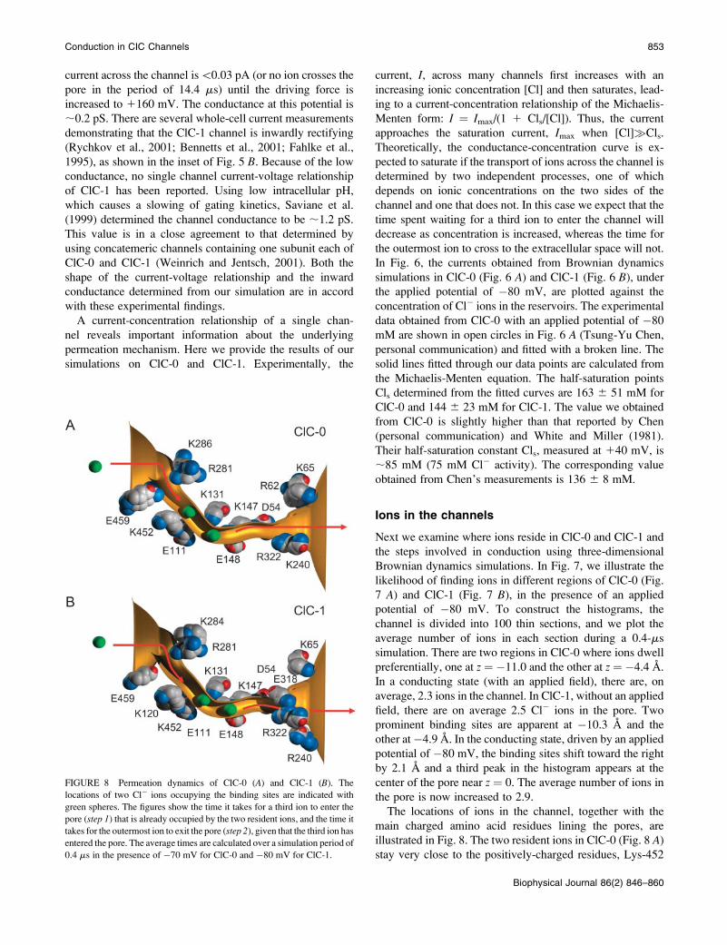
The locations of ions in the channel, together with the
main charged amino acid residues lining the pores, are
illustrated in Fig. 8. The two resident ions in ClC-0 (Fig. 8 A)stay very close to the positively-charged residues, Lys-452
FIGURE 8 Permeation dynamics of ClC-0 (A) and ClC-1 (B). The
locations of two Cl� ions occupying the binding sites are indicated with
green spheres. The figures show the time it takes for a third ion to enter the
pore (step 1) that is already occupied by the two resident ions, and the time it
takes for the outermost ion to exit the pore (step 2), given that the third ion has
entered the pore. The average times are calculated over a simulation period of
0.4 ms in the presence of �70 mV for ClC-0 and �80 mV for ClC-1.
Conduction in CIC Channels 853
Biophysical Journal 86(2) 846–860

and Lys-131. Comparing the position of these ions to the
innermost two ions trapped in the crystallized E148A EcClC
channel, the positions of the ions in our simulation are
shifted slightly toward the extracellular side of the channel.
This shift reflects the presence of an additional positively-
charged residue, Arg-62, lining the extracellular end of the
ClC-0 pore and attracting Cl� ions deeper into the channel.
For conduction to take place, a third ion must enter the pore
from the intracellular side of the channel. This disrupts the
stable equilibrium of the two resident ions. With an applied
potential of �70 mV, it takes on average 125 ns for a third
ion to stumble into ClC-0 from the intracellular reservoir.
Once three ions are in the pore, the outermost ion near the
Lys-131 residue manages to climb out of the energy well
in ;70 ns. Thus, there are two rate-limiting steps in the
outward conduction process. When the polarity of the
applied field is reversed, the locations of the binding sites
remain unaltered. Here, the step that limits the number of
ions the channel can process is the entrance of a third ion
from the extracellular space into the pore, which on average
takes nearly 200 ns. Once three ions are in the pore, the
innermost ion, located near the Lys-452 residue, is expelled
from the pore almost instantaneously.
The dynamics of ion permeation in ClC-1 are similar to
that in ClC-0 (see Fig. 8 B). The two resident ions are
situated near the Lys-131 and Lys-147 residues, shifted
slightly toward the extracellular side compared to those in
ClC-0. The dwell histogram obtained from ClC-1 shows the
presence of a third peak, in the extracellular side of the
channel at z¼�13.4 A. This indicates that a third ion spends
a considerable amount of time in the channel before
a successful conduction event occurs. The location of these
three peaks in ClC-1 corresponds almost exactly to the
position of the three chloride ions in the crystal structure of
E148A EcClC (Dutzler et al., 2003). Under the influence of
an applied potential of �80 mV, a third ion enters the pore,
this process taking on average 270 ns. With three ions in the
pore, it takes[1 ms for the outermost ion to exit the pore.
The number of ions the channel can process is thus limited
by the energy barrier created by the additional negatively-
charged residue Glu-318.
The conduction process across ClC-0 and ClC-1 is
broadly similar to that in the KcsA potassium channel,
where a third K1 ion entering the central cavity accelerates
toward the selectivity filter and effects conduction by knock-
off (Allen and Chung, 2001). Pusch et al. (1995) showed that
current through the ClC-0 channel is reduced substantially
when two permeating ionic species, Cl� and NO3�, are
mixed compared to that observed when only one of the two
ions is present in the solution. This so-called ‘‘anomalous
mole fraction’’ behavior can only occur if the pore has to be
occupied by two or more ions for conduction to take place.
The results of our simulation are consistent with this
experimental deduction.
Ionic pathways and sequence alignments
There are two caveats to the approach we use in constructing
the models. These are to do with, firstly, the method of
creating an ionic path across the EcClC protein and, sec-
ondly, the sequence alignments used for creating the homol-
ogy models of ClC-0 and ClC-1. We address these issues
in this section.
To ascertain the reliability of the open-state EcClC
configuration that we use, we compare the pathway to open
structures created using the high-resolution x-ray structures
of the wild-type EcClC and E148A EcClC reported by
Dutzler et al. (2003) (Protein Data Bank accession code
1OTS and 1OTT, respectively). When the E148A EcClC
structure is aligned with the low-resolution structure, the
three embedded Cl� ions in the E148A structure pass
through the center of the ionic pathway created using the
crystal coordinates reported in Dutzler et al. (2002). The
expansion of both high-resolution structures are carried out
using the same procedures detailed previously, except that
the trapped Cl� ions are not moved during the expansion
process. In Fig. 9, we show the open-state configurations
created with the low-resolution wild-type EcClC (goldsurface) and high-resolution E148A EcClC crystal struc-
tures. Three Cl� ions in the x-ray structure (Protein Data
Bank accession code: 1OTT) are indicated as green spheres,
and the central axis of the ionic path we created is shown as
a dotted green line. The two pore shapes are virtually
indistinguishable. The high-resolution structure has seven
residues less than that of the low-resolution structure: it
is five residues shorter at the N-terminus and two at the
C-terminus. When we select atoms in the vicinity of the pore,
FIGURE 9 The ionic pathway created from the high-resolution x-ray
structures. The shape of the pore is virtually indistinguishable from that
created from the low-resolution x-ray structure, illustrated as a gold surface.
Three Cl� ions are indicated as green spheres, and the central axis of the pore
created from the high-resolution structures is shown as a dotted line.
854 Corry et al.
Biophysical Journal 86(2) 846–860

;25% of all atoms, and compare the open-state configura-
tion derived from the E148A high-resolution structure with
that derived from the wild-type low-resolution structure, we
find that the root-mean square average difference in atom
position is 1.01 A. We then used the axial coordinates of the
open state mapped through the E148A EcClC to create an
open-state configuration for the high-resolution wild-type
EcClC structure. The equivalent root-mean square deviation
of atom position is 0.95 A. The results of these tests show
that the structure of the open pore we construct is in-
dependent of the original structure used to create it. We
demonstrate later that the shape of the energy profiles and the
conduction properties obtained from two different open-state
models, one obtained from the low-resolution x-ray structure
(Dutzler et al., 2002) and the other obtained from the WT
high-resolution structure (Dutzler et al., 2003), are virtually
identical.
In Fig. 10, we compare the energy profiles and dwell
histograms obtained from the ClC-0 models based on the
low-resolution (left-hand column) and high-resolution
(right-hand column) x-ray structures. The sequence align-
ment used to create the homology models is the same as the
one we used throughout, except the glutamine residues at
positions 73, 142, and 310 are replaced by glycine (i.e., we
use the ClustalW alignment with manual adjustment). In the
ClC-0 notation, these residue numbers correspond to 89,
160, and 344. The energy landscapes encountered by a single
Cl� ion traversing channel show a deep well centered at
�8 A. The two profiles, in the presence of an applied
potential of 120 mV, are virtually identical. The maximum
depth of the well obtained from the low-resolution structure
is 2.1 kT shallower than that obtained from the high-
resolution structure (47.4 kT vs. 49.5 kT). The two dwell
histograms illustrated in Fig. 10 are similar. Both reveal two
prominent binding sites in the channel, centered at z ¼ �11
and �4.4 A. The average number of ions in the channel in
the conducting state for the low-resolution homology model
(C) is 2.31, compared to 2.45 for the high-resolution
homology model (D). The difference is not statistically
significant. There is no significant difference in the magni-
tudes of current flowing across the two models, determined
by using Brownian dynamics. With an applied potential of
�40 mV, the currents we observe, during the simulation pe-
riod of 17.2 ms, are �0.35 6 0.08 and �0.33 6 0.08 pA for
the low-resolution and high-resolution models, respectively.
From these results, we conclude that the open-state configu-
rations created from the x-ray structures of Dutzler et al.
(2002, 2003) are almost identical, and the conductance
properties deduced from the two models do not differ
appreciably.
We next examine whether or not the ClustalW alignment
of ClC-0 without manual adjustment (see the Method
section) can also reproduce any of the experimental
observations. The locations of the charged amino acid
residues along the pore are shown in Fig. 11 A. Two
positively-charged residues guarding the external gate of
the channel in the manually adjusted alignment, namely Arg-
322 and Lys-240, are now replaced with glutamate residues,
FIGURE 10 Energy profiles and
dwell histograms obtained from the
models based on the pathways created
from the low-resolution (A and C) and
high-resolution x-ray structures (B
and D).
Conduction in CIC Channels 855
Biophysical Journal 86(2) 846–860

Glu-232 and Glu-235 (see Fig. 2 B). There are two net negat-ively-charged residues lining the pore, compared to six net pos-
itive charges in the alignment of Dutzler et al. (2002). The
energy landscape encountered by a Cl� ion, shown in Fig.
11 B, reveals several features that are not present in the pro-
file illustrated in Fig. 3 A, reproduced here in dashed line. Theenergy well is narrower and shallower than that obtained
from the homology model constructed from the alignment
using Dutzler et al. (2002). The depth of the well at z¼�7 A
is 32 kT, compared to 47 kT in the profile shown in Fig. 3 A.Also, there is a prominent energy barrier of ;3.5 kT located
at z ¼112 A. The dwell histogram obtained in the presence
of an applied potential of �80 mV is illustrated in Fig. 11 C.
FIGURE 11 Homology model constructed from the ClustalW alignment
with no manual adjustment. The locations of the charged residues lining the
pore are indicated in A. In B, the energy profile encountered by a single ion
traversing the pore (solid line) is compared to that obtained from the model
based on the manually adjusted alignment (broken line). The dwell
histogram in C shows one prominent peak. For comparison, the histogram
illustrated in Fig. 7 A is reproduced as light shade.
FIGURE 12 Mutant ClC-0 channel. The Glu-459 residue guarding the
intracellular gate of ClC-0 is changed to arginine and then the mutant
channel is characterized. The potential energy profile in the absence of an
applied potential (A) obtained from the mutant channel (solid line) is
compared with the unmutated channel (broken line), reproduced from Fig. 3
A. In the dwell histogram, an additional binding site appears near the
intracellular entrance of the pore (B). The current-voltage relationship (C)
remains virtually unchanged from that obtained from the unmutated ClC-
0 channel. The experimental measurements (open circles) obtained byMiller
(1982) is superimposed on the simulated data (solid circles).
856 Corry et al.
Biophysical Journal 86(2) 846–860

Instead of having two prominent peaks, the histogram shows
one main peak centered at z ¼ �5.6 A. For comparison, the
histogram shown in Fig. 7 A is superimposed on this figure.
There are, on average, 1.4 ions in the channel, compared to
2.4 ions in the histogram illustrated in Fig. 7 A. A resident
ion is permanently trapped at the binding site, unable to exist
outside the pore. As a second ion enters from the intracellular
reservoir, it is forced out of the channel by the Coulomb
repulsion of the trapped ion. We measure the current across
the model channel using Brownian dynamics. In the
simulation period of 9.6 ms with an applied potential of
�80 mV, the observed current is�0.09 pA. No ions traverse
in the opposite direction during the same simulation period,
even at an applied potential of �160 mV. We thus conclude
that the homology model constructed with the ClustalW
alignment with no manual adjustment is incapable of rep-
licating the experimental observations.
Finally, we examine the effects of performing a point
mutation on the native ClC-0 model, mutating position 459
from glutamate to arginine. This residue is identified as
arginine in the alignment given by Dutzler et al. (2002),
whereas our ClustalW alignment identifies it as glutamate.
We demonstrate that the permeation dynamics of the E459R
ClC-0 mutant involve an extra ion, but is otherwise similar to
that of ClC-0. Harking back to Fig. 8, we note that the Glu-
459 residue is located near the entrance of the intracellular
vestibule. Fig. 12 A compares the energy wells encountered
by a Cl� ion moving through the mutant channel (solid line)and ClC-0 (broken line, reproduced from Fig. 3 A).Changing a negative residue to a positive residue is reflected
in the depth and the width of the energy well: it is 8.3 kT
deeper and slightly broader than that of the native ClC-0.
Now three Cl� ions occupy the pore, oscillating from their
equilibrium positions at z¼ �16.3,�10.7, and�4.7 A (Fig.
12 B). These positions are close to three positively-charged
residues, Arg-459, Arg-281, and Lys-131. In the presence of
an applied potential of�80 mV, we find that there are almost
3.5 ions on average in the mutant channel, indicating that the
presence of the fourth ion destabilizes the three-ion
equilibrium and causes conduction. The entry of the fourth
Cl� ion in the pore from the intracellular reservoir is the rate-
limit step in conduction in this mutant channel, taking on
average 270 ns at �80 mV. The three resident ions shuffle
toward the extracellular side of the pore to accommodate the
additional ion that enters. Once the outermost ion reaches the
position of Lys-147, it dwells there temporarily, but usually
exits within a few nanoseconds. Although conduction across
the E459R mutant pore becomes a four-ion process, instead
of being a three-ion process, the magnitude of currents across
the pore remains unaltered. In Fig. 12 C, the current-voltagecurve for the mutant pore is illustrated. The curve is linear
through the origin, with the core conductance of 10.3 6 0.3
pS. Our simulated data shows excellent agreement with
corresponding measurements reported by Miller (1982),
which are superimposed (open circles).
DISCUSSION
In this article, we have attempted to relate the molecular
structure of the ClC chloride channels to some of their
macroscopically observable properties using several differ-
ent computational approaches. Using molecular dynamics,
an open-state structure of the prokaryotic ClC channel is first
created by moving the atoms that are occluding the ion-
conducting path. The x-ray structures of Dutzler et al. (2002,
2003) correspond to a closed state, although whether the pore
is closed by a slow or fast gating mechanism or through
a structural change in the process of crystallization is not
known. In creating an open conformation, we have made the
minimum possible adjustments to the original crystallo-
graphic structure. Only those atoms that sterically impede
ionic passage are slowly pushed outward, leaving all other
residues largely unperturbed. The narrowest segment of the
pore in the open-state conformation we create is just under
2.5 A. We have ascertained in a preliminary study that the
conductance is not appreciably affected when the radius of
this segment is reduced to 2.3 or 2.1 A. When the channel is
in a conducting state, the constricted segment of the pore
near E148 must be wider than the van der Waals radii of Cl�
and I� ions, which are 1.80 and 2.15 A, respectively, and
also must accommodate NO�3 ions. Thus, the minimum pore
radius of 2.5 A we adopted in this study is likely to be a good
approximation.
In building the models, we assume that the open-state
shape of the prokaryotic ClC channel is the same as that for
ClC-0 and ClC-1, and that the structural features that confer
specific characteristics of each ClC isoform are the polar and
charged amino acid residues near the ion-conducting path.
Whether this assumption is justified will remain unknown
until the structures of these two channels are determined,
crystallographically or otherwise, although a recent study
suggests our assumption is plausible (Estevez et al., 2003).
The three-dimensional atomic models of ClC-0 and ClC-1
we constructed by replacing amino acid residues that are
not conserved with EcClC successfully reproduce the ex-
perimentally observed conductances and the shape of the
current-voltage curves. The accurate replication of the
experimental data with our Brownian dynamics simulations
is not brought about by judiciously adjusting free param-
eters. There is one unknown constant that features in each of
the Langevin and Poisson’s equations. The first one of these
is the friction coefficient, g, which is related to the diffusion
coefficient, D, by the Einstein relation, g ¼ kT/mD, where mis the mass of the ion. Molecular dynamics simulations were
carried out by Allen et al. (2000) to obtain estimates of
diffusion coefficients of biologically important Na1, K1,
and Cl� ions in various segments of the KcsA and schematic
channels. In the hydrophobic chamber, their diffusion
coefficients are reduced to ;38% of bulk diffusion on
average. In this study, we use 50% of the bulk values in the
pore. Unlike in the Poisson-Nernst-Planck theory, where
Conduction in CIC Channels 857
Biophysical Journal 86(2) 846–860

conductance scales linearly with assumed D, conductancededuced from Brownian dynamics simulations is less sen-
sitive to this parameter. The outward and inward currents
across the potassium channel are reduced only slightly as DK
is reduced from the bulk value to 10% of this (Chung et al.,
1999).
In solving Poisson’s equation, in this and all our previous
studies, we use dielectric constants of 2, 60, and 80 for
the protein, channel, and reservoir. Unlike water and lipid,
which form homogeneous media, proteins are quite het-
erogeneous, exhibiting large variations in polarizability
depending on whether we are dealing with the interior or
exterior of a protein (see Schutz and Warshel, 2001). There
are several microscopic investigations of the dielectric
constant of proteins from molecular dynamics simulations
(Smith et al., 1993; Simonson and Brooks, 1996; Pitera et al.,
2001). The dielectric constant for the whole protein, ac-
cording to these studies, varies between 10 and 40, but
when only the interior region of the protein consisting of the
backbone and uncharged residues is considered, the value
drops to 2 or 4. From a microscopic point of view, this
should make assigning a fixed ep value to an entire protein incontinuum electrostatic calculations problematic. The effects
of changing ep from 2 to 3.5 and 5 were examined by Chung
et al. (2002), using the KcsA potassium channel. They
showed that the precise value adopted in solving Poisson’s
equation has negligible effects on the macroscopic properties
derived from Brownian dynamics simulations. For further
discussion on this issue, see Burykin et al. (2002, 2003).
Assigning the appropriate value of dielectric constant of
water, ew, within the ion channel is also nontrivial. In bulk
water, molecules polarize so as to shield interactions within
the dielectric media by a factor of ;1/80. However, given
the preferential alignment of water in narrow pores, es-
pecially in regions of high charge, this shielding is likely
to be far less effective. In theory, to determine ew, one can
either examine the interaction of the fluctuating dipole
moment with a reaction field acting at the boundary—the
so-called Kirkwood-Frolich technique (Frolich, 1968)—or
measure the induced polarization in response to an applied
electric field (Heinz et al., 2001; Kusalik et al., 1994). In
practice, neither method gives a reliable answer when they
are applied to channel-like geometries that contain ions. This
issue clearly deserves further investigation. In the meantime,
we have been consistently adopting the value of ew as 60,
under the assumption that the polar residues on the protein
wall are acting partially like water molecules in shielding
ionic charges. In a number of different types of ion channels
that we studied using Brownian dynamics, the use of ew¼ 60
in the narrow pore successfully reproduced many of the
experimentally determined properties.
Incorporating the atomic models of ClC-0 and ClC-1 in
three-dimensional Brownian dynamics, we are able to make
a number of predictions that can be tested experimentally.
Among these are the conductance-concentration profiles for
ClC-0 and ClC-1. For both, we obtain the half-saturation
values of ;150 mM, in the same range as many cationic
channels, such as the potassium channels (Coronado et al.,
1980; Chung et al., 2002). Theoretically, the conductance-
concentration curve is expected to saturate if the transport
through the channel is determined by two independent
processes, of which only one depends on ionic concen-
trations on the two sides of the channel. In ClC-0 and ClC-1,
outward conduction involves two such steps as illustrated in
Fig. 8. The first is the entry of a third ion into the channel
from the intracellular space, which depends on the ionic
concentration and the applied potential. The second step is
the outermost ion climbing out of the energy well and into
the extracellular space, which is independent of the ionic
concentration and depends solely on the applied potential.
Thus, the current in these channels first increases and then
saturates with increasing ionic concentration, following the
Michaelis-Menten form derived in Chung et al. (1999).
Finally, we show that a single point mutation of the Glu-459
residue guarding the intracellular gate to arginine causes an
increase in the number of ion binding sites from two to three
(Fig. 12). The current-voltage curve, however, remains
virtually unchanged. Although the mutant and wild-type
channels will be indistinguishable macroscopically, an
additional Cl� ion is predicted to be present in the mutant
x-ray structure.
Our studies have shed light on the detailed mechanism
of ion permeation in ClC channels. The success of our
technique of constructing models of these channels has
prompted us to examine how the conduction properties of
EcClC, ClC-0, and ClC-1 will be affected following
theoretical mutations and to study other ClC isoforms,
whose single channel properties have not yet been
characterized. It has not been possible to measure currents
across some ClC-type channels, such as the prokaryotic ClC
channels, probably because currents are too small to be
resolved experimentally. For these, we are able to model site-
directed mutagenesis and ascertain which residues need to be
mutated to enhance the magnitude of currents flowing across
the pores. The results of our mutation studies will be reported
in detail elsewhere. In studying the family of ClC channels,
we can now make testable predictions while refining our
models as new experimental data comes to hand. Thus, our
understanding of the mechanics of ion channels can progress
through a fruitful interaction between theory and experiment.
The calculations upon which this work is based were carried out using the
Compaq AlphaServer Supercomputer of The Australian National Univer-
sity Supercomputer Facility. We thank Dr. David K. Bisset for creating an
open-state structure of the EcClC channel and Dr. Tsung-Yu Chen for
making his unpublished data available to us. Dr. Chen’s experimental
measurements are reproduced in Fig. 6 with his kind permission.
This work was supported by grants from the Australian Research Council,
the Australian Partnership of Advanced Computing, and the National
Health and Medical Research Council of Australia.
858 Corry et al.
Biophysical Journal 86(2) 846–860

REFERENCES
Allen, T., and S. H. Chung. 2001. Brownian dynamics study of an open-state KcsA potassium channel. Biochim. Biophys. Acta. 1515:83–91.
Allen, T. W., S. Kuyucak, and S. H. Chung. 2000. Molecular dynamicsestimates of ion diffusion in model hydrophobic and KcsA potassiumchannels. Biophys. Chem. 86:1–14.
Bennetts, B., M. L. Roberts, A. H. Bretag, and G. Y. Rychkov. 2001.Temperature dependence of human muscle ClC-1 chloride channel.J. Physiol. 535:83–93.
Brooks, B. R., R. E. Bruccoleri, B. D. Olafson, D. J. States, S.Swaminathan, and M. Karplus. 1983. CHARMM: a program formacromolecular energy, minimization, and dynamics calculations.J. Comp. Chem. 4:187–217.
Burykin, A., C. N. Schutz, J. Villa, and A. Warshel. 2002. Simulations ofion current in realistic models of ion channels: the KcsA potassiumchannel. Proteins. 47:265–280.
Burykin, A., M. Kato, and A. Warshel. 2003. Exploring the origin of theion selectivity of the KcsA potassium channel. Proteins. 52:412–426.
Chen, Y. T., and C. Miller. 1996. Nonequilibrium gating and voltagedependence of the ClC-0 Cl� channel. J. Gen. Physiol. 108:237–250.
Chung, S. H., M. Hoyles, T. W. Allen, and S. Kuyucak. 1998. Study ofionic currents across a model membrane channel using Browniandynamics. Biophys. J. 75:793–809.
Chung, S. H., T. W. Allen, M. Hoyles, and S. Kuyucak. 1999. Permeationof ions across the potassium channel: Brownian dynamics studies.Biophys. J. 77:2517–2533.
Chung, S. H., T. W. Allen, and S. Kuyucak. 2002. Conducting-stateproperties of the KcsA potassium channel from molecular and Browniandynamics simulations. Biophys. J. 82:628–645.
Coronado, R., R. L. Rosenberg, and C. Miller. 1980. Ionic selectivity,saturation, and block in a K1-selective channel from sarcoplasmicreticulum. J. Gen. Physiol. 76:425–446.
Corry, B., T. W. Allen, S. Kuyucak, and S. H. Chung. 2001. Mechanisms ofpermeation and selectivity in calcium channels. Biophys. J. 80:195–214.
Corry, B., S. Kuyucak, and S. H. Chung. 2003. Dielectric self-energy inPoisson-Boltzmann and Poisson-Nernst-Planck models of ion channels.Biophys. J. 84:3594–3606.
Doyle, D. A., J. M. Cabral, R. A. Pfuetzner, A. Kuo, J. M. Gulbis, S. L.Cohen, B. T. Chait, and R. MacKinnon. 1998. The structure of thepotassium channel: molecular basis of K1 conduction and selectivity.Science. 280:69–77.
Duan, D., S. Cowley, B. Horowitz, and J. R. Hume. 1999. A serine residuein CLC-3 link phosphorylation-dephosphorylation to chloride channelregulation by cell volume. J. Gen. Physiol. 113:57–70.
Dutzler, R., E. B. Campbell, M. Cadene, B. T. Chait, and R. MacKinnon.2002. X-ray structure of a ClC chloride channel at 3.0 A reveals themolecular basis of anion selectivity. Nature. 415:287–294.
Dutzler, R., E. B. Campbell, and R. MacKinnon. 2003. Gating theselectivity in ClC chloride channels. Science. 300:108–112.
Edwards, S., B. Corry, S. Kuyucak, and S. H. Chung. 2002. Continuumelectrostatics fails to describe ion permeation in the gramicidin channel.Biophys. J. 83:1348–1360.
Estevez, R., B. C. Schroeder, A. Accardi, T. J. Jentsch, and M. Pusch. 2003.Conservation of chloride channel structure revealed by an inhibitorbinding site in ClC-1. Neuron. 38:47–59.
Fahlke, C. 2001. Ion permeation and selectivity in ClC-type chloridechannels. 2001. Am. J. Physiol. Renal Physiol. 280:F748–F757.
Fahlke, C., R. Rudel, N. Mitrovic, M. Zhou, and A. L. George, Jr. 1995. Anaspartic residue important for voltage-dependent gating of human musclechloride channels. Neuron. 15:463–472.
Friedrich, T., T. Breiderhoff, and T. J. Jentsch. 1999. Mutational analysisdemonstrates that ClC-4 and ClC-5 directly mediate plasma membranecurrents. J. Biol. Chem. 274:896–902.
Frolich, H. 1968. Theory of Dielectrics. Clarendon Press, Oxford, UK.
Heinz, T. N., W. F. van Gunsteren, and P. H. Hunenberger. 2001.Comparison of four methods to compute the dielectric permittivity ofliquids from molecular dynamics simulations. J. Chem. Phys. 115:1125–1136.
Hoyles, M., S. Kuyucak, and S. H. Chung. 1998. Solutions of Poisson’sequation in channel-like geometries. Comp. Phys. Comm. 115:45–68.
Jentsch, T. J., K. Steinmeyer, and G. Schwarz. 1990. Primary structure ofTorpedo marmorata chloride channel isolated by expression cloning inXenopus oocytes. Nature. 348:510–514.
Jentsch, T. J., T. Friedrich, A. Schriever, and H. Yamada. 1999. The ClCchloride channel family. Pflugers Arch. 437:783–795.
Jentsch, T. J., V. Stein, F. Weinreich, and A. A. Zdebik. 2002. Molecularstructure and physiological function of chloride channels. Physiol. Rev.82:503–568.
Kawasaki, M., M. Suzuki, S. Uchida, S. Sasaki, and F. Marumo. 1995.Stable and functional expression of the ClC-3 chloride channel insomatic cell lines. Neuron. 14:1285–1291.
Kusalik, P. G., M. E. Mandy, and I. M. Swishchev. 1994. The dielectric-constant of polar fluids and the distribution of the total dipole-moment.J. Chem. Phys. 100:7654–7664.
Li, S. C., M. Hoyles, S. Kuyucak, and S. H. Chung. 1998. Browniandynamics study of ion transport in the vestibule of membrane channels.Biophys. J. 74:37–47.
Lorenz, C., M. Pusch, and T. J. Jentsch. 1996. Heteromultimeric CLCchloride channels with novel properties. Proc. Natl. Acad. Sci. USA.93:13362–13366.
Ludewig, U., M. Pusch, and T. J. Jentsch. 1996. Two physically distinctpores in the dimeric ClC-0 chloride channel. Nature. 383:340–343.
Maduke, M., C. Miller, and J. A. Mindell. 2000. A decade of ClC chloridechannels: structure, mechanism, and many unsettled questions. Annu.Rev. Biophys. Biomol. Struct. 29:411–438.
Middleton, R. E., D. J. Pheasant, and C. Miller. 1996. Homodimericarchitecture of a ClC-type chloride channel. Nature. 383:337–340.
Miller, C. 1982. Open-state substructure of single chloride channels fromTorpedo electroplax. Phil. Trans. Roy. Soc. Lond. B299:401–411.
Moy, G., B. Corry, S. Kuyucak, and S. H. Chung. 2000. Tests of continuumtheories as models of ion channels. I. Poisson-Boltzmann theory versusBrownian dynamics. Biophys. J. 78:2349–2363.
Pitera, J. W., M. Falta, and W. F. van Gunsteren. 2001. Dielectric propertiesof proteins from simulation: the effects of solvent, ligands, pH, andtemperature. Biophys. J. 80:2546–2555.
Press, W. H., B. P. Flannery, S. A. Teukolsky, and W. T. Vetterling. 1989.Numerical Recipes. Cambridge University Press, Cambridge, UK.
Pusch, M., U. Ludewig, A. Rehfeldt, and T. J. Jentsch. 1995. Gating of thevoltage-dependent chloride channel ClC-0 by the permeant anions.Nature. 373:527–531.
Rychkov, G. Y., M. Pusch, M. L. Roberts, and A. H. Bretag. 2001.Interaction of hydrophobic anions with the rat skeletal muscle chloridechannel ClC-1: effects on permeation and gating. J. Physiol. 530:379–393.
Saviane, C., F. Conti, and M. Pusch. 1999. The muscle chloride channelClC-1 has a double-barreled appearance that is differentially affected indominant recessive myotonia. J. Gen. Physiol. 113:457–469.
Schutz, C. N., and A. Warshel. 2001. What are the dielectric ‘‘constants’’ ofproteins and how to validate electrostatic models. Proteins. 44:400–417.
Simonson, T., and C. L. Brooks, Iii. 1996. Charge screening and thedielectric constant of proteins: insights from molecular dynamics. J. Am.Chem. Soc. 118:8452–8458.
Smith, P. E., R. M. Brunne, A. E. Mark, and W. F. van Gunsteren. 1993.Dielectric properties of trypsin inhibitor and lysozyme calculated frommolecular dynamics simulations. J. Phys. Chem. 97:2009–2014.
Conduction in CIC Channels 859
Biophysical Journal 86(2) 846–860

Steinmeyer, K., B. Schwappach, M. Bens, A. Vandewalle, and T. J.Jentsch. 1995. Cloning and functional expression of rat CLC-5, a chloridechannel related to kidney disease. J. Biol. Chem. 270:31172–31177.
Thompson, J. D., D. J. Higgins, and T. J. Gibson. 1994. CLUSTAL W:improving the sensitivity of progressive multiple sequence alignmentthrough sequence weighting, position-specific gap penalties and weightmatrix choice. Nucleic Acids Res. 22:4673–4680.
van Gunsteren, W. F., and H. J. C. Berendsen. 1982. Algorithms forBrownian dynamics. Mol. Phys. 45:637–647.
Vonoye, C. G., and A. L. George, Jr. 2002. Functional characterization ofrecombinant human ClC-4 chloride channels in cultured mammaliancells. J. Physiol. 539:373–383.
Weinreich, F., and T. J. Jentsch. 2001. Pores formed by single subunits inmixed dimers of different CLC chloride channels. J. Biol. Chem.276:2347–2353.
White, M. M., and C. Miller. 1981. Probes of the conduction process ofa voltage-gated Cl� channel. J. Gen. Physiol. 78:1–18.
860 Corry et al.
Biophysical Journal 86(2) 846–860
Related Documents


![Genome-wide identification and expression analysis of the CLC … · 2020. 12. 11. · [23], etc. All of the CLC proteins have a highly con-served voltage-gated chloride channel (Voltage-gate](https://static.cupdf.com/doc/110x72/6106dd3e9ccfce08576786e6/genome-wide-identification-and-expression-analysis-of-the-clc-2020-12-11-23.jpg)