PDHonline Course C278 (10 PDH) Conducting Soil Investigations for Structure Foundations 2012 Instructor: George E. Thomas, PE PDH Online | PDH Center 5272 Meadow Estates Drive Fairfax, VA 22030-6658 Phone & Fax: 703-988-0088 www.PDHonline.org www.PDHcenter.com An Approved Continuing Education Provider

Welcome message from author
This document is posted to help you gain knowledge. Please leave a comment to let me know what you think about it! Share it to your friends and learn new things together.
Transcript
PDHonline Course C278 (10 PDH)
Conducting Soil Investigations forStructure Foundations
2012
Instructor: George E. Thomas, PE
PDH Online | PDH Center5272 Meadow Estates Drive
Fairfax, VA 22030-6658Phone & Fax: 703-988-0088
www.PDHonline.orgwww.PDHcenter.com
An Approved Continuing Education Provider

www.PDHcenter.com PDH Course C278 www.PDHonline.org
Conducting Soil Investigations for Structure Foundations
George E. Thomas, PE A. Principles of Investigations 1. General. a. Objectives. The purpose of an investigation is to obtain information relating to foundation conditions and to natural construction materials commensurate with the type of structure to be build. The investigation is conducted in the office, in the field, and in the laboratory. Characteristics of subsurface conditions are developed in progressively greater detail as exploratory work proceeds. Investigations are usually performed in phases so the conditions can be reevaluated and investigation procedures revised to obtain maximum information at the lowest cost. Data obtained must be organized to clearly show significant features of the occurrence and properties of the materials. Specific objectives of an investigation are to determine (as required): • The regional geology influence on materials, site, and structure characteristics. • The location, sequence, thickness, and areal extent of each s tra tum, including a descr ip t ion and classification of the
materials and their structure and stratification in the undisturbed state. Significant geologic features such as concretions, fabric, and mineral and chemical constituents should be noted.
• The depth to and type of bedrock: − location, − depth of weathering, − sequence, − seams, − thickness, − joints, − areal extent, − fissures, − attitude, − faults, − soundness, and − other structural features.
• The characteristics of the ground water: − depth to water table, − whether the water table is perched or normal, − depth of and pressure in artesian zones, − quantity and types of soluble salts or other minerals present, and − water chemistry particularly for any contaminants.
• Properties of the materials by methods appropriate for the investigation stage, the type of structure, and detailed engineering data:
− describe and identify materials in place visually, and determining in-place density. − obtain disturbed samples, describing and identifying them visually, and determining their in-place water content and index
properties. Engineering properties may be estimated on the basis of the classification along with results of laboratory index tests.
− indirect methods performed in the field such as geologic interpretations, in-place tests, or surface geophysical methods, using results of direct explorations and other tests to provide necessary correlations.
− observe performance of previously constructed structures built of or placed on similar materials. − observe natural slopes of similar materials.
© George E. Thomas Page 2 of 127
− obtain undisturbed samples, identifying them visually, describing their undisturbed state, determining in-place density and water content, and obtaining index and engineering properties by laboratory tests.

www.PDHcenter.com PDH Course C278 www.PDHonline.org
− perform tests in the field such as standard penetration tests, cone penetration tests, bearing capacity tests, pile loading tests, permeability tests, pressuremeter tests, dilatometer tests, and vane shear tests.
b. Classification of Structure Foundations. Investigation requirements for foundations vary over a wide range and may include consideration of the foundation material use both for the foundation and for the structure. Foundations for structures can be conveniently grouped into four classes to assist in determining type and degree of foundation investigation required: (1) The engineering properties of the material are unacceptable, and the soil or rock must be partially or entirely removed to provide a satisfactory foundation for the structure under consideration. (2) The soil or rock in place will provide the structure foundation, either with or without ground improvement. (3) The soil or rock provides both the foundation and a major part of the structure, with material from the required foundation excavation provided for use in the structure. (4) Same as (3), except that substantial amounts of material are needed for the structure in addition to that available from the required excavation. For structures constructed on rock, in addition to investigations of the rock foundation, a soil investigation is made in which primary concerns are depth to bedrock, stability of slopes, and difficulty of excavation. Stability of reservoir rims should also be considered and investigated if problem areas are identified. Materials from excavations should be used for other construction purposes when feasible. For example, a site considered suitable for a concrete dam will usually require temporary cofferdams, and materials from required excavations could be used for that purpose. Aggregate sources for concrete and for filters for earth and rockfill dams also need to be located and investigated. For structures founded on soil, the primary objective of a soil investigation is to determine soil volume change characteristics that may result in foundation settlement or heave. Dispersivity and soluble salts could also be important, depending on the structure type. If heavy loading and wet soil conditions are anticipated, the shear strength should be investigated. For structures which use materials from required excavations, materials must be considered from both stability and utilization standpoints. Stability of slopes, both in cuts and f i l ls , is a pr imary considerat ion. Compressibility varies in importance, approximately commensurate with the importance of the structure itself having little significance where roads and laterals are concerned but major importance where paved highways and large lined canals with large structures are required. In expansive soils and in-place low density soils, the probability and magnitude of uplift and collapse must be evaluated. Permeability is important on canals and laterals. Where a choice in location is possible, workability of materials is of major economic importance. For this reason, cuts into bedrock are normally avoided. 2. Sources of Map and Photo Information. • U.S. Department of Agriculture (Aerial Photography). The U.S. Department of Agriculture (USDA) is an excellent source
of aerial photography. The Aerial Photography Field Office (APFO) is the depository and reproduction facility of the U.S. Department of Agriculture’s aerial photography, housing aerial film acquired by the Agricultural Stabilization and Conservation Service (ASCS), Natural Resources Conservation Service (NRCS), and the U.S. Forest Service. Combined aerial photography covers about 95 percent of the conterminous United States. APFO’s film holdings include black and white panchromatic, natural color, and color infrared films (CIR) with negative scales ranging from 1:6000 to 1:120,000. National High Altitude Photography (NHAP) is a primary source of new aerial photography. APFO libraries keep the original CIR positives which are flown at a scale of 1:60,000 with each exposure covering 68 square miles.
• The U.S. Geological Survey (USGS). The USGS produces information in many forms that can be useful in local engineering
studies: maps, scientific reports, geodetic data, aerial photographs, bibliographic data, and other forms. Most of these products are available from one or more of the following sources:
• USDA, for aerial • USGS Distribution; for maps and published reports • USGS Earth Science Information Center Open-File Report unit; for open-file reports • Earth Science Information Centers (ESICs); for maps, reports, aerial photographs, and general information on many earth
science topics • Water Resources Division (WRD); for state water data reports
© George E. Thomas Page 3 of 127
• National Technical Information Service (NTIS)

www.PDHcenter.com PDH Course C278 www.PDHonline.org
Most maps and reports are available for reference in USGS libraries, in selected U.S. Government Printing Office (GPO) Depository Libraries, and in large university libraries and are available commercially. c. USGS Products. Maps, cross sections, and related indexes. • Topographic maps are the most common USGS maps. For most par ts of the United States, topographic maps are
available in several scales: − 1 : 24,000 − 1 : 100,000 − 1 : 250,000 − 1 : 500,000 − 1 : 1,000,000 − 1 : 62,500 and 1 : 63,360 scale maps are available for some areas of the country. − 1 : 50,000 and 1 : 100,000 scale county maps are being prepared in selected States. − Topographic maps are available commercially and from USGS Distribution and Earth Science Information Centers. − Topographic data (in digital form) called digital elevation models (DEMs) and digital line graphs (DLGs), are available
from ESICs, the EROS Data Center (EDC), and commercial vendors. − Specific information about topographic maps is presented State by State in the USGS.
• Geologic maps are of many kinds: bedrock geology and surficial geology are the most common, but maps showing depth to bedrock, bedrock structure contours, coal or other mineral resources, basement geology, and similar maps also are considered geologic maps. Cross sections are presented on many geologic and hydrologic maps but are not generally available separately. Bedrock and surficial geologic maps are available in many scales; such maps, at detailed scales (1 : 24,000 or larger), have been published for only about one-third of the United States. To identify maps available for a specific place, use the USGS Geologic Map Index for that State or the USGS GEOINDEX data base, which contains the same information but is more up to date. The State geoscience agencies can be helpful in identifying such geologic maps.
• Hydrologic maps, like geologic maps, can be of many kinds: water table contours, aquifers, water qual i ty, hydrologic uni ts (watersheds), flood hazards, and a like. These kinds of maps are published by the USGS and other Federal, State, and local government agencies. The USGS hydrologic maps are published either as thematic maps available from USGS Distribution or in open-file reports available from the ESIC Open-File Report unit. Hydrologic maps are listed in the annual catalogs.
• Geophysical maps show information about geomagnetism, gravity, radioactivity, and many other geophysical characteristics. Geochemical maps show information related to stream sediment samples processed in search of mineral resources. Seismicity maps show information about earthquake history, severity, and risk. Hazard maps can show areas of swelling clays, landslides and related hazards, avalanche danger, volcanic and earthquake hazards, and other geologic hazards. These maps are available either as published USGS thematic maps from USGS Distribution or as open-file reports from the ESIC Open-File Report unit.
• River surveys and wetlands inventory maps may be of particular interest to investigators studying river sites. River surveys were mostly conducted between 30 and 60 years ago in support of large-scale engineering projects. Some maps are still available showing river courses and profiles. Wetlands inventory maps, which show kinds of wetland ecosystems, are being made by the U.S. Fish and Wildlife Service for 7.5-minute quadrangles.
• Out-of-print (o.p.) USGS maps generally are available for reference in libraries and from other sources. Blueprint copies of o.p. topographic maps are available from ESICs. Generally, reproductions of o.p. thematic maps are available from the U.S. National Archives, Cartographic Division. Another source of o.p. maps is map dealers, of whom some specialize in old, rare maps.
• Other miscellaneous maps are available from the USGS, including folios (sets of environmental maps of many selected areas showing geologic, hydrologic, land use, historical, and other features) and wilderness area maps.
© George E. Thomas Page 4 of 127
d. USGS Technical Reports. The USGS publishes several kinds of technical reports. These reports are useful in many engineering disciplines, including engineering geology and hydrology; most are listed in annual catalogs and bibliographies.

www.PDHcenter.com PDH Course C278 www.PDHonline.org
© George E. Thomas Page 5 of 127
e. USGS Publications. Publications catalogs have been published annually. This USGS information has been available since 1982; earlier publications are compiled into larger catalogs: • Publications of the U.S. Geological Survey, 1971-8 1 • Publications of the U.S. Geological Survey, 1962-70 • Publications of the U.S. Geological Survey, 1879- 1961 These are available from USGS Distribution and from ESICs. A monthly list, "New Publications," of new USGS publications is available free from USGS. Bibliographies of USGS publications on selected topics are available as open-file reports, bulletins, and other publications. Additional unpublished bibliographies on selected geologic topics are also available from the Geologic Inquiries Group (GIG). A complete bibliography of USGS publications, "Publications of the U.S Geological Survey", includes information on all but the topographic maps described above and is available on CD ROM from the American Geological Institute. Several USGS data bases of bibliographic and similar information are available to help identify USGS products: • Earth Science Data Directory lists earth science data files and data bases from many sources, including many outside the USGS. • Map and Chart Information System is a data base listing USGS and other maps and charts. • Cartographic Catalog is a data base listing kinds of maps and such map-related information as map dealers, geographic
software vendors, and producers of globes. • Aerial Photography Summary Record System is a data base for information about aerial photographic coverage of the United
States. • GEOINDEX is a data base of bibliographic and related information about geologic maps of the United States. • Library data base provides bibliographic information about recent acquisitions of the USGS library; this data base includes
many non-USGS publications. • Selected Water Resources Abstracts presents abstracts of water resources reports and articles published by many organizations. f. USGS Software, Data, and Related Products. The USGS has published computer software. The USGS Open-File Report 89-68 1 (available from the ESIC Open-File Report unit) lists USGS software published as of June 1989. g. USGS Remote Sensing Products. The USGS has acquired many aerial photographs, satellite photographs, orthophotos, and many kinds of satellite imagery such as: • Landsat multispectral scanner (MSS) • Landsat thematic mapper (TM) • side-looking airborne radar (SLAR) • advanced very-high resolution radiometer (AVHRR) Aerial photographs are available for the entire United States, and in many places, an option of scales and acquisition dates is available. Orthophotos are made from aerial photographs that have been geometrically corrected to eliminate displacements present in the aerial photographs; these are available for many parts of the country. For assistance, in ordering any kind of aerial photograph or satellite image, contact an ESIC for help in identifying the best coverage, which varies depending on how it will be used. The USGS has also collected geophysical data, including gravity data, aeromagnetic and aeroradioactivity. For detailed information about the availability of these kinds of geophysical data for a specific area, contact the USGS Branch of Geophysics. Information about magnetic declination is available from the National Geomagnetic Information Center. The National Uranium Resource Evaluation (NURE) program collected a large amount of general aeromagnetic data and stream-sediment-sample geochemical data for most of the country; NURE data are available in published form from the ESIC Open-File Report unit and in digital form from the EDC.

www.PDHcenter.com PDH Course C278 www.PDHonline.org
h. USGS Topographic Maps. A topographic map is useful in the design and construction of most civil engineering structures. Before undertaking the painstaking job of mapmaking, a thorough search should be made for existing maps which cover the area of the structure and potential sources of construction materials. The USGS has made a series of standard topographic maps covering the United States and Puerto Rico. The unit of survey for USGS maps is a quadrangle bounded by parallels of latitude and meridians of longitude. Quadrangles are available generally covering 7.5 minutes, 15 minutes, and 30 minutes of latitude and longitude, and possibly at several scales such as 1 : 24,000 (1 inch equals 2000 feet for 7.5 minutes of latitude and longitude). Each quadrangle is designated by the name of a city, town, or prominent natural or historical feature within it; the margins of each map are printed with the names of adjoining quadrangle maps. In addition to published topographic maps, the USGS has other information for mapped areas; for example, location and true geodetic position of triangulation stations and elevation of permanent benchmarks established by the USGS. River survey maps are important to dam planning. These are topographic strip maps that show the course and fall of a stream; configuration of the valley floor and the adjacent slopes; and locations of towns, scattered buildings or houses, irrigation ditches, roads, and other cultural features. River survey maps were prepared in connection with the classification of public lands; hence, most of them are of areas in the Western United States. If a valley is less than 1.6 km (1 mi) wide, the topography is usually shown to 30 m (100 ft) or more above the water surface; if the valley is flat and wide, topography is shown for a strip of 1.6 to 3.0 km (1 to 2 mi) parallel to the river or stream. The usual scale is 1 : 31,680 or 1 : 24,000, and the normal contour interval is 6 m (20 ft) on land and 1.5 m (5 ft) on the water surface. Many of these maps include proposed dam sites on larger scale topography and show a profile of the stream. i. USGS Geologic Maps. Important information is obtainable from geologic maps. These maps identify the rock uni ts d irect ly under lying the project area. Characteristics of rocks are of major importance in selection of a dam site and in design of water-retaining and conveyance structures. Many surface soils are closely related to the type of rock from which they are derived, but if the soil has been transported, it may overlie an entirely different rock type. When the influence of climate, relief, and geology of the area is considered, reasonable predictions can be made of the type of soil which will be encountered or of the association with a particular parent material. Subsurface conditions can often be deduced from the three-dimensional information given on geologic maps. These maps are especially valuable in areas where only limited information on soils or agricultural classifications are available; for example, in arid or semiarid regions where soils are thin. Commonly available general purpose geologic maps (e.g., USGS-type maps) are not detailed enough for site-specific needs. Geology for engineering exploration, design, and construction must be generated for the specific application. Horizontal scales of 1 in to 50 or 100 ft and contour intervals of 1 to 5 ft are common. Site-specific maps are usually generated using aerial photographs flown for the application, although small maps may be prepared using plane table or ground survey data. Site geologic maps are used for the design, construction, and maintenance of engineering features. These maps concentrate on geologic and hydrologic data pertinent to the engineering needs of a project and do not address the academic aspects of the geology. Rocks are identified on geologic maps by name and geologic age. The smallest rock unit mapped is generally a formation, but smaller subdivisions such as members or beds may be delineated. A formation is an individual bed or several beds of rock that extend over a fairly large area and can be clearly differentiated from overlying or underlying beds because of a distinct difference in lithology, structure, or age. The areal extent of these formations is indicated on geologic maps by means of letter symbols, color, and symbolic patterns.
© George E. Thomas Page 6 of 127
Geologic maps often show one or more geologic sections. A section is a graphic representation of the disposition of the various strata in depth, along an arbitrary line usually marked on the map. Geologic sections are interpretive and should be used with that in mind. The vertical scale may be exaggerated. Sections prepared solely from surface data are less accurate; sections prepared from boring records or mining evidence are more reliable. A section compiled to show the sequence and stratigraphic relations of the rock units in one locality is called a columnar section; it shows only the succession of strata and not the structure of the beds as does the geologic section.

www.PDHcenter.com PDH Course C278 www.PDHonline.org
© George E. Thomas Page 7 of 127
Several types of geologic maps are available. A bedrock or areal geologic map shows a plan view of the bedrock and surficial materials in the area. This type of map shows the boundaries of formations, inferred where the units are covered by soil or plant growth, and may include one or more geologic sections. Areal maps do not show soil except for indicating thick deposits of alluvial, glacial, or windblown materials. In areas of complex geology where exposures of bedrock are scarce, location of the contacts between formations is often indicated as approximate. Surficial geologic maps differentiate surface materials of the area according to their geologic categories such as stream alluvium, glacial gravel, and windblown sand. These maps indicate the areal extent, characteristics, and geologic age of surface materials. Areal (bedrock) geologic maps of moderately deformed areas often show enough structural detail to provide an understanding of the structural geology of that region; in many instances, generalized subsurface structure can be deduced from distribution of the formations on the map. In highly complex areas, where a great amount of structural data is necessary for an interpretation of the geology, special structural geologic maps are prepared. In addition to giving the geologic age of mapped rocks, some maps briefly describe the rocks. Many maps, however, lack a lithologic description. An experienced geologist may make certain assumptions or generalizations based only on the age of rock by making analogies with other areas. Geologic literature on the entire area must be consulted for more detail and for certain identification of the lithology. Engineering information can be obtained from geologic maps if the user has the appropriate background and experience. It is possible to prepare a preliminary construction materials map by study of a basic geologic map, together with all collateral geologic data that pertain to the area shown. Similarly, preliminary foundation and excavation conditions, as well as surface and ground-water data, can be deduced from geologic maps. Such information is valuable for preliminary planning activities but is not a substitute for detailed field investigations during the feasibility and specifications stages. j. Agricultural Soil Maps. A large portion of the United States has been surveyed by the USDA. These investigations are of surficial materials. The lower limit of soil normally coincides with the lower limit of biological activity and root depth. Soils are examined down to rock or down to 2 m (80 in) possibly deeper in some cases. Soils are classified according to soil properties including color, structure, texture, physical constitution, chemical composition, biological characteristics, and morphology. The USDA publishes reports of these surveys in which the different soils are described in detail; interpretations aregiven for agricultural and certain nonagricultural uses. Each report includes a map of the area surveyed (usually a county) showing by pedological classification the various kinds of soils present. In addition to published soil maps, many areas are shown in which individual farms and ranches are mapped using the same system of soil classification and interpretation. Agricultural soil maps can be obtained from the State or local office of the NRCS, from a county agent, or from a congressional representative. Many libraries keep published soil surveys on file for reference. Also, resources conservation district offices and county agricultural extension offices have copies of local soil surveys that can be used for reference. Out-of-print maps and other unpublished surveys may be available for examination from the USDA, county extension agents, colleges, universities, and libraries. Using the agricultural soil classification system, soil surveys have been made for many river basins in the 17 Western States to classify land for irrigation based on physical and chemical criteria. Inquiry should be made at the local U.S. Department of the interior, Bureau of Reclamation (USBR) area offices concerning availability of soil data for these areas. When applying agricultural soil maps to exploration for foundations and construction materials, some knowledge of the pedological system of classification is necessary. This system is based on the premise that water leaches inorganic colloids and soluble material from upper layers to create distinct layers of soil. The depth of leaching action depends on the amount of water, permeability of the soil, and length of time involved. The surface layer lacks in fines which are accumulated in a subsurface layer containing these fines in addition to its original fines. Deep soil beneath the subsurface layer has been little affected by water and remains essentially unchanged. Exceptions are in the Southeastern United States (or other humid areas) where some soils are weathered to greater depths. Three layers are typically developed from the surface downward: the A horizon, the B horizon, and the C horizon. In some soils, an E horizon (a more leached horizon) is between the A and B horizons. In detailed descriptions, these horizons may be subdivided into A1, A2, B1, B2, etc. Soils of the United States are divided into main divisions depending on the cause of profile development and on the magnitude of the cause. The main soil divisions are further divided into "suborders," then into "great groups" based on the combined effects of climate, vegetation, and topography. Within each "great group," soils are divided into soil series, of which each has the same degree of development, climate, vegetation, relief, and parent material. In the pedological classification system, all soil profiles of a certain soil series are similar in all respects, except for variation in texture or grain size of the topsoil or A horizon. Typically, the soil series are named after a town, county, stream or similar geographical source where the soil series was first identified.

www.PDHcenter.com PDH Course C278 www.PDHonline.org
© George E. Thomas Page 8 of 127
The final soil mapping unit, which is called the soil phase, consists of the soil series name plus the textural classification of the topsoil or A horizon plus other features such as slope, flooding, etc. The USDA's textural classification system is different from the Unified Soil Classification System used for engineering purposes. Figure 1 shows textural classification of soils used by USDA. The chart shows terminology used for different percentages of: • clay. . . . particles smaller than 0.002 mm, • silt. . . . . 0.002 to 0.05 mm, and • sand. . . . 0.05 to 2.0 mm. Note the term "loam" is a mixture of sand, silt, and clay within certain percentage limits. Other terms (used as adjectives to the names) obtained in the USDA system are: • gravelly. . . rounded and subrounded particles from 2 to 75 mm (3/4 to 3 in), • cobbly . . . 75 to 250 mm (3 to 10 in), and • stony . . . . sizes greater than 250 mm (10 in). The textural classification given as part of the soil name on the agricultural soil map refers to material in the A horizon only; hence, this is not of much value to an engineer interested in the entire soil profile. The combination of soil series name and textural classification to form a soil type, however, provides a considerable amount of significant data. For each soil series, the following can be obtained: • texture, • degree of compaction, • presence or absence of hardpan or rock, • lithology of the parent material, and • chemical composition. A table of estimated engineering sieve sizes, the Unified Soil Classification System and American Association of State Highway and Transportation Officials (AASHTO) classification, and Atterberg limits are included in each published soil survey. In addition, actual test data from the survey area is published in some cases. The following example is taken from the Soil Survey Data Base available from offices of USDA's Natural Resources Conservation Service. The "Cecil Series" is described by a general geographical distribution of the series, the rocks from which it was derived, and information on climate. A comparison is made to series with associated or related soil series. Additional discussion concerns the range in characteristics of the Cecil Series as well as: relief, drainage, vegetation, land use, and remarks; and distribution of the series by States and location. A soil pedon description for the Cecil Series is given as follows. Agricultural soil classifications used for engineering purposes are of limited value. Information of this type is qualitative rather than quantitative; but, if carefully evaluated, agricultural soil classifications can often be used to advantage in the reconnaissance stage and in planning subsurface exploration. Additional information of how soil surveys are made can be found in the Soil Survey Manual, an publication of the Natural Resources Conservation Service. The agricultural soil survey report is designed to provide information useful to the farmer and to the agricultural community. However, in addition to the soil maps and soil profile descriptions contained in these reports, other valuable information is included. The reports discuss: • topography, • ground surface conditions, • obstructions to movement on the ground, • natural vegetation, • size of property parcels, • land utilization, • farm practice and cropping systems, • meteorological data, • drainage, • flood danger, • irrigation,

www.PDHcenter.com PDH Course C278 www.PDHonline.org
• water supply and quality, nearness to towns, roads, and railroads, • electric power, and • similar data.
Figure 1. textural classification of soils used by USDA
3. Remote Sensing Techniques. a. General. Remote sensing is the gathering of data concerning the earth’s surface without coming into contact with it. Remote sensing is performed using devices such as cameras, thermal radiometers, multispectral scanners, and microwave (radar) detectors. Engineering and geologic interpretation of remotely sensed data may be simple or complicated, depending on the nature of the data and the objective of the study. Remote sensing is a tool which makes some tasks easier, which enables some tasks to be performed that could not otherwise be accomplished, but which may be inappropriate for other tasks. Depending on the situation, remote sensing may be extremely valuable or totally inappropriate. Some remote sensing interpretations can be used directly and with confidence; but for most applications, field correlations are essential to establish reliability. Appropriate specialists should be consulted when evaluating situations to determine if remote sensing methods can provide useful data. b. Nonphotographic.
© George E. Thomas Page 9 of 127

www.PDHcenter.com PDH Course C278 www.PDHonline.org
© George E. Thomas Page 10 of 127
1. Scanners. Electronic sensors are used that have less spatial resolution than photographs, but which can obtain a variety of spectral data and thus allow a wide variety of image processing and enhancement techniques. Scanners can be either airborne or satellite. 2. Video. A television type system is used. Video systems still have lower spatial resolution than photographic cameras, but provide products more quickly and are excellent for reconnaissance type work. They are highly useful for mapping and monitoring linear features such as rivers and canals. c. Resolution. 1. Spatial. The sharpness of an image and the minimum size of objects that can be distinguished in the image are a function of spatial resolution. 2. Spectral. The width of a part of the electromagnetic spectrum is the spectral resolution. Certain portions of the electromagnetic spectrum, including the visible, reflective infrared, thermal infrared, and microwave bands, are useful for remote sensing applications. Materials have spectral signatures and distinctive absorptive and reflective spectral characteristics which allow them to be recognized. Given sufficient multispectral data, digital image processing can produce unique spectral signatures to be identified. Instrument limitations, cost limits on computer processing, or lack of spectral contrast may preclude unambiguous identification of some materials. d. Photography. Photography provides the best spatial resolution, but less flexibility in spectral data collection and image enhancement.
1. General. Several types of aerial photographs are available. An aerial photograph is a picture of the earth’ s surface taken from the air. It may be a vertical photograph or an oblique photograph more or less inclined. High oblique photographs include the horizon; low obliques do not. The vertical photograph is commonly used for topographic mapping, agricultural soil mapping, vegetation mapping, and geological interpretations. 2. Panchromatic. Panchromatic photography (black and white) records images essentially across the entire visible spectrum. In aerial photography, blue is generally filtered out to reduce the effects of atmospheric haze. 3. Natural Color. Images are recorded in natural visible colors. In addition to black and white aerial photographs available as contact prints, color photography can be obtained either as positive transparencies or opaque prints, black and white infrared, or color infrared. By using appropriate film and filters, photography may be obtained ranging from ultraviolet to near infrared. 4. Multispectral. Photographs acquired by multiple cameras simultaneously recording different portions of the spectrum can enhance interpretation. Multiband cameras employing four to nine lenses and various lens, filter, and film combinations make possible photography within narrow wavelength bands to emphasize various soil, moisture, temperature, and vegetation effects to aid photo interpretation. Except where dense forest cover obscures large areas, aerial photographs reveal every natural and human endeavor on earth within the resolution of the photographic system. Relationships are exposed which could not be detected on the ground under normal or routine surface investigation. Identification of features shown on a photo is facilitated by stereoscopic examination. Knowledge of geology and of soil science will assist in interpreting aerial photographs for engineering uses. Aerial photographs are often used for locating areas to be examined and sampled in the field. Virtually the entire United States has been covered by aerial photography. An index map of the United States is available from the USGS and USDA. When ordering photographs, specify: • Contact prints or enlargements, glossy, matte finish, or Cronapaque • Location should be given by range, township, and section, latitude and longitude • State and county and the preceding location(s) can be shown on an enclosed index map of the area. • Where possible, use the airphoto index to determine project symbol, film roll number, and exposure number to expedite the
request. • Stereoscopic coverage should be requested for most uses. Aerial mosaics covering some of the United States are also available. A mosaic is an assemblage of individual aerial photographs fitted together to form a composite view of an entire area of the earth. An index map showing the availability of aerial mosaics of the

www.PDHcenter.com PDH Course C278 www.PDHonline.org
© George E. Thomas Page 11 of 127
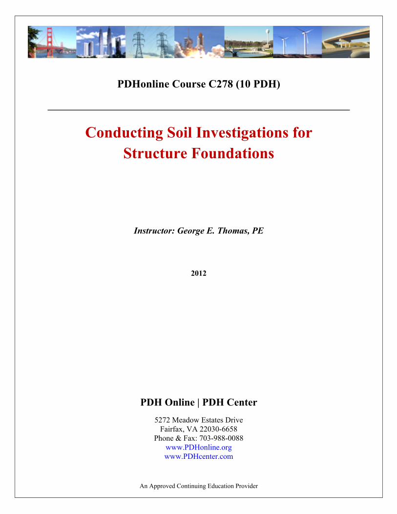
United States, including the coverage and the agencies holding mosaic negatives, is available from the USGS Map Information Office. Equipment is commercially available to produce orthophotographs that have a uniform scale and from which radial and relief displacement due to topography have been removed. Orthographs overprinted with contour lines can be acquired, if desired. Aerial photograph interpretation of earth materials and geologic features is relatively simple and straightforward, but experience is required. Diagnostic features include terrain position, topography, drainage and erosional features, color tones, and vegetation cover. Interpretation is limited mainly to surface and near-surface conditions. Special cases arise, however, where features on a photograph permit reliable predictions to be made of deep, underground conditions. Although interpretation can be rendered from any sharp photograph, resolution is a limiting factor because small-scale photographs limit the amount of detailed information that can be obtained. The scale of 1: 20,000 is satisfactory for some engineering and geologic interpretation of surface materials. Small-scale photographs are used for highly detailed work such as for reservoir clearing estimates and for geologic mapping of damsites and reservoir areas. Aerial photographs can be used to identify many terrain types and landforms. Stereoscopic photograph inspection of regional topography, local terrain features, and drainage conditions usually will suffice to identify the common terrain type. This permits the possible range in soil and rock materials to be anticipated and their characteristics to be defined within broad limits. Geologic features that may be highly significant to the location or performance of engineering structures can often be identified from aerial photographs. In many instances, these features can be more readily identified on an aerial photograph than on the ground. However, aerial photograph interpretation is applicable only to those features that develop recognizable geomorphic features such as surface expressions such as drainage patterns, old river channels, and alignment of ridges or valleys. Joint systems, landslides, fault zones, lineations, folds, and other structural features are sometimes identified quickly in an aerial photograph, whereas it may be difficult to find them on the ground. The general attitude, bedding, and jointing of exposed rock strata, as well as the presence of dikes and intrusions, can often be seen in aerial photographs. The possibilities of landslides into open cuts and of seepage losses from reservoirs can be assessed. Figures 2 and 3 are examples of identifiable geologic features determined from aerial photographs by an experienced interpreter using stereoscopic procedures. 5. Color Infrared. Images use part of the visible spectrum and part of the near infrared, but resultant colors are not natural. Infrared film is commonly used and is less affected by haze than other types. Other remote sensors use thermal, infrared, microwave, and radar wavelengths. Such phenomena as differences in the earth’s gravity and magnetic properties may be measured to afford additional interpretive tools. e. Thermal Infrared Imagery. Thermal infrared systems create images by scanning and recording radiant temperatures of surfaces. Some characteristics of thermal image data produce digital image data which enable computer image processing, and others are unique to thermal infrared images which makes them valuable interpretive tools. Thermal infrared imagery can be analyzed using conventional photo interpretation techniques in conjunction with knowledge of thermal properties of materials and instrument and environmental factors that affect data. Where thermal characteristics of a material are unique, thermal infrared imagery is easily and confidently interpreted. Vegetation patterns can be distinguished and can relate to subsurface conditions such as seepage beneath or through an exis t ing dam. However , thermal characteristics of a material can vary with ambient temperature, moisture content, differential solar heating, and topography, and make interpretation difficult and ambiguous. f. Multispectral Scanner Imagery (MSS). MSS images are a series of images of the same target, acquired simultaneously in different parts of the electromagnetic spectrum. The MSS images are an array of lines of sequentially scanned digital data, as opposed to the simultaneously exposed area of a photograph. They may have unique distortions and may or may not have high resolution and information content. Scanner systems consist of scanning mechanisms, spectral separators, detectors, and data recorders. Because a digital image is actually an array of numerical data, the image can be manipulated by a computer for a variety of purposes. Geometric distortions caused by sensor characteristics can be removed, or distortions can be introduced if desired. Computer processing can be used to precisely register a digital image to a map or another image. Various techniques can be used to improve image quality and interpretability. Various types of data (for example, thermal and visible imagery or a digital image and digitized gravity data) can be merged into a single image. Subtle information, difficult to interpret or even to detect, sometimes
www.PDHcenter.com PDH Course C278 www.PDHonline.org
can be extracted from an image by digital processing.
Figure 2. Rock strata illustrating folding in sedimentary rocks
(A) Satanka. (B) Lyons formation, (C) Morrison formation (D) Lower and Middle Dakota formation.
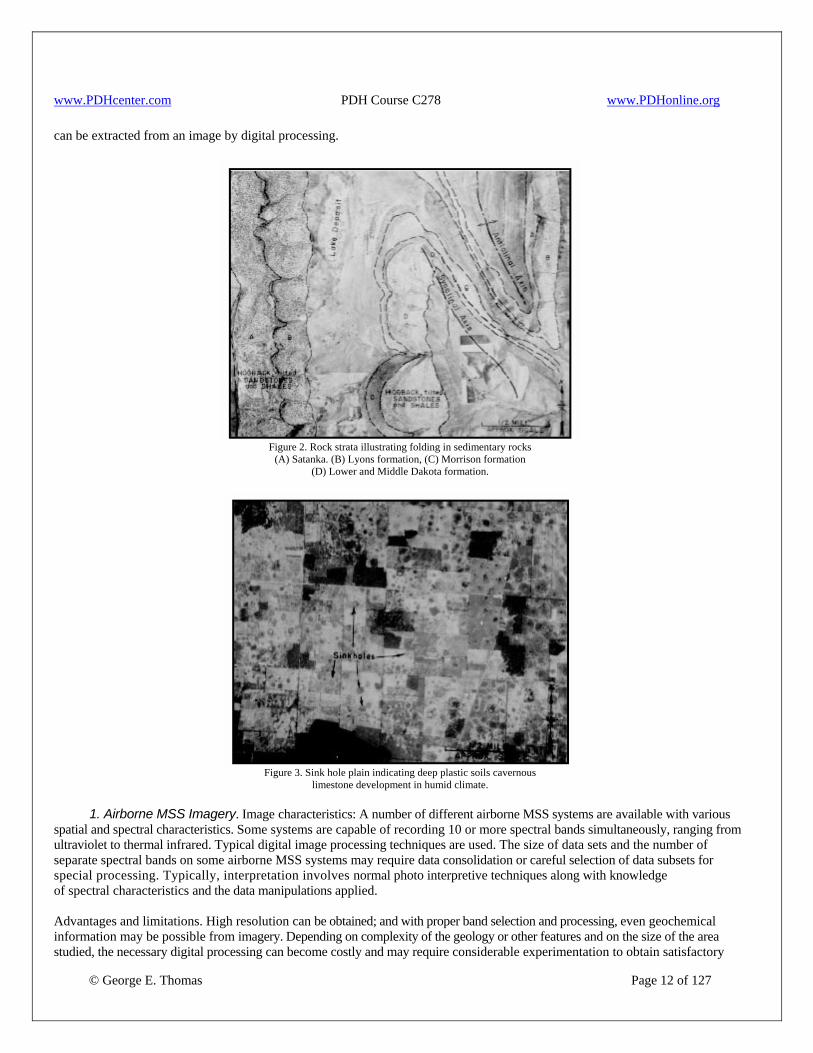
Figure 3. Sink hole plain indicating deep plastic soils cavernous
limestone development in humid climate. 1. Airborne MSS Imagery. Image characteristics: A number of different airborne MSS systems are available with various spatial and spectral characteristics. Some systems are capable of recording 10 or more spectral bands simultaneously, ranging from ultraviolet to thermal infrared. Typical digital image processing techniques are used. The size of data sets and the number of separate spectral bands on some airborne MSS systems may require data consolidation or careful selection of data subsets for special processing. Typically, interpretation involves normal photo interpretive techniques along with knowledge of spectral characteristics and the data manipulations applied.
© George E. Thomas Page 12 of 127
Advantages and limitations. High resolution can be obtained; and with proper band selection and processing, even geochemical information may be possible from imagery. Depending on complexity of the geology or other features and on the size of the area studied, the necessary digital processing can become costly and may require considerable experimentation to obtain satisfactory

www.PDHcenter.com PDH Course C278 www.PDHonline.org
© George E. Thomas Page 13 of 127
results. 2.Satel l i te MSS Imagery .Landsat is the U. S. satellite for civilian remote sensing of Earth' s land surface : The Landsat MSS records four broad bands at 80- meter resolution. Though primarily oriented toward agricultural applications, it has proved useful for some geologic applications. The current Landsat is equipped with a thematic mapper (TM), which enhances spatial and spectral resolution compared to the MSS. The TM records seven narrow bands at 30-meter resolution and is more useful for geologic and geotechnical engineering applications. A French satellite, Satellite Pour l’Observation de la Terre (SPOT), provides panchromatic imagery with up to 10-meter spatial resolution and MSS imagery at 20 meter resolution and is capable of stereo imaging. Satellite imagery provides a synoptic view of a large area, which is valuable for regional studies, but the limited resolutions currently available restrict its value for engineering geology and geotechnical work. g. Radar Imagery. Radar is an active remote sensing method (as opposed to passive methods like photography and thermal infrared) and is independent of lighting conditions and cloud cover. Some satellite radar imagery is available, but like Landsat, it is more useful for regional geologic studies than for engineering geologic or geotechnical application. Side-looking airborne radar (SLAR) produces a radar image of the terrain on one side of the airplane carrying the radar equipment (equivalent to a low-oblique airphoto). This imagery is useful when studying regional geologic faulting patterns and can be used to assist in determining specific sites for detailed fault investigations. Image characteristics. Radar imagery has some unusual distortions which require care when data are interpreted. Resolution is affected by several factors, and the reflectivity of target materials must be considered. Analysis and interpretation of radar imagery require knowledge of the imaging system, wave length polarization, look angle, and responses of target materials. Advantages and disadvantages. Radar can penetrate clouds and darkness and, to some extent, vegetation or even soil. Distortions and resolution can complicate interpretation, as can a lack of multispectral information. h. Applications to Geotechnical Engineering and Geology. In general, the most useful form of remote sensing for geotechnical applications is aerial photography because of its high resolution, high information content, and low cost. Various scales of aerial photographs are valuable for regional studies and site studies, for both detection and mapping of a wide variety of geologic features of importance to engineering investigations. Application of other forms of remote sensing to engineering work depends on the nature of the problem to be solved and the characteristics of site geology or other features. Some problems can be best solved using remote sensing; for others, remote sensing is of no value. In some cases, the only way to determine if remote sensing can be useful is to try it. i. Availability of Imagery. The entire United States has been imaged by the Landsat MSS. Partial Landsat TM and SPOT coverage of the United States is also available. The SLAR coverage of a portion of the United States is available. Other types of imagery are also available, but generally only for limited areas. j. Mission Planning. Numerous factors make planning a nonphotographic mission more complicated than planning for a conventional aerial photographic mission. Remote sensing mission planning should be done by, or in consultation with, an expert in the field. The cost of remote sensing data acquisition can be relatively accurately estimated. However, cost of interpretation is a function of the time and image processing required; this cost is difficult to estimate accurately. Some forms of data are inexpensive to acquire and require little processing to be useful. Other forms may be costly to acquire and may or may not require considerable processing. 4 Site Investigations and Land Form Types. a.General. Surface investigations are generally limited to geologic mapping of water resource development sites, outlining areas of potential construction materials, and assessing hazardous waste remedial sites. However, useful relationships exist between surface land forms and the subsurface soil and rock conditions. The ability to recognize these landforms on topographic maps, on aerial photographs, and during preliminary site reconnaissance, when combined with a geologic knowledge of the area, is very important when characterizing a site and when locating potential sources for construction materials.

www.PDHcenter.com PDH Course C278 www.PDHonline.org
© George E. Thomas Page 14 of 127
Soils in their geologic context are defined by their mechanism of deposition which, in turn, usually results in distinct landforms (physiographic surface expressions). A good representation of the subsurface soil engineering characteristics can be made by detailed surface mapping. However, a complete understanding of subsurface soils conditions can only be obtained through careful subsurface investigations. Knowledge of surface conditions can be used to economically lay out a subsurface investigation program. Most water resource development projects are sited in river valleys containing a variety of soil (surficial deposits). Typically, valley sedimentation consists of alluvial channel, flood plain, and terrace deposits. Slope wash and colluvial materials, landslides, and alluvial fans are often found on the valley slopes but can also impinge upon the valley floor. Side ridges, especially where auxiliary structures may be sited, often contain residual soils forming in place. Other types of surficial deposits that form structural foundations are glacial, windblown (eolian), and lacustrine in origin. The physical description and properties of the types of soils most common to water resource development projects are described below, and some broad generalizations are made about the engineering characteristics and applications of these soil types associated with their particular landforms. b. Alluvial Deposits. These deposits constitute the largest group of transported soils. Alluvial deposits are stream transported and are usually bedded or lenticular, but massive deposits may also occur. The different types of sedimentary processes, combined with different source materials and the energy required during the transportation process, leads to materials ranging from well to poorly graded.
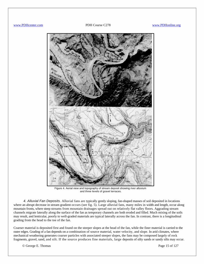
1. Stream Channel Deposits. Typically, high energy stream channel deposits contain sands, gravels and cobbles. The size and extent of channel deposits can vary greatly. Channel deposits may comprise the entire valley floor and may be quite deep. In a wide valley, a meandering or braided stream may distribute channel deposits widely, resulting in thin, widespread layers or very irregular lenses of sand and gravel. These deposits can be poorly to well graded and can provide sources of filter materials and concrete aggregate. Stream channel deposits represent paths of potential high seepage. Variation in soil properties, seepage, consolidation, and possible low shear strengths may make them undesirable foundations for water retention structures. Figure 4 shows an aerial view and topography of river alluvium and terrace deposits. The presence of a high water table is often a major difficulty in using channel deposits for borrow. When borrowing of material is being considered from a river deposit downstream from a water retention structure, such operations may change the tailwater characteristics of the stream channel, and the spillway and outlet works may have to be designed for the modified channel conditions. 2. Flood Plain Deposits. The low gradient sections of nearly all streams have flood plains. Their surface expression is usually that of a smooth flat strip of land just above the stream channel. Clay, silt, and sand are typical soils of flood plains. Most flood plain deposits were once carried as sediment load while in the swiftly moving flood water of a channel (high energy) but settled out on the flood plain when water overflowed the channel and slowed (lower energy). In broad valleys, flood plains may be miles wide and may be flooded on an annual or more frequent basis. Flood plain deposits are often the source of the impervious zones for water retention structures. 3. Terrace Deposits. Terraces are located above the flood plain (see fig. 4). They are usually elongate deposits along the streamcourse and have either a flat or a slight downstream dip on their upper surface. They also have well-delineated steep slopes, downward from the terrace on the stream side and upward on the valley wall side of the terrace. Along degrading streams, the alluvium in terrace deposits generally has the same size range as adjacent channel deposits. Terrace deposits can be sources of sand and gravel, but often are of limited extent and may require washing and processing.
www.PDHcenter.com PDH Course C278 www.PDHonline.org
Figure 4. Aerial view and topography of stream deposit showing river alluvium
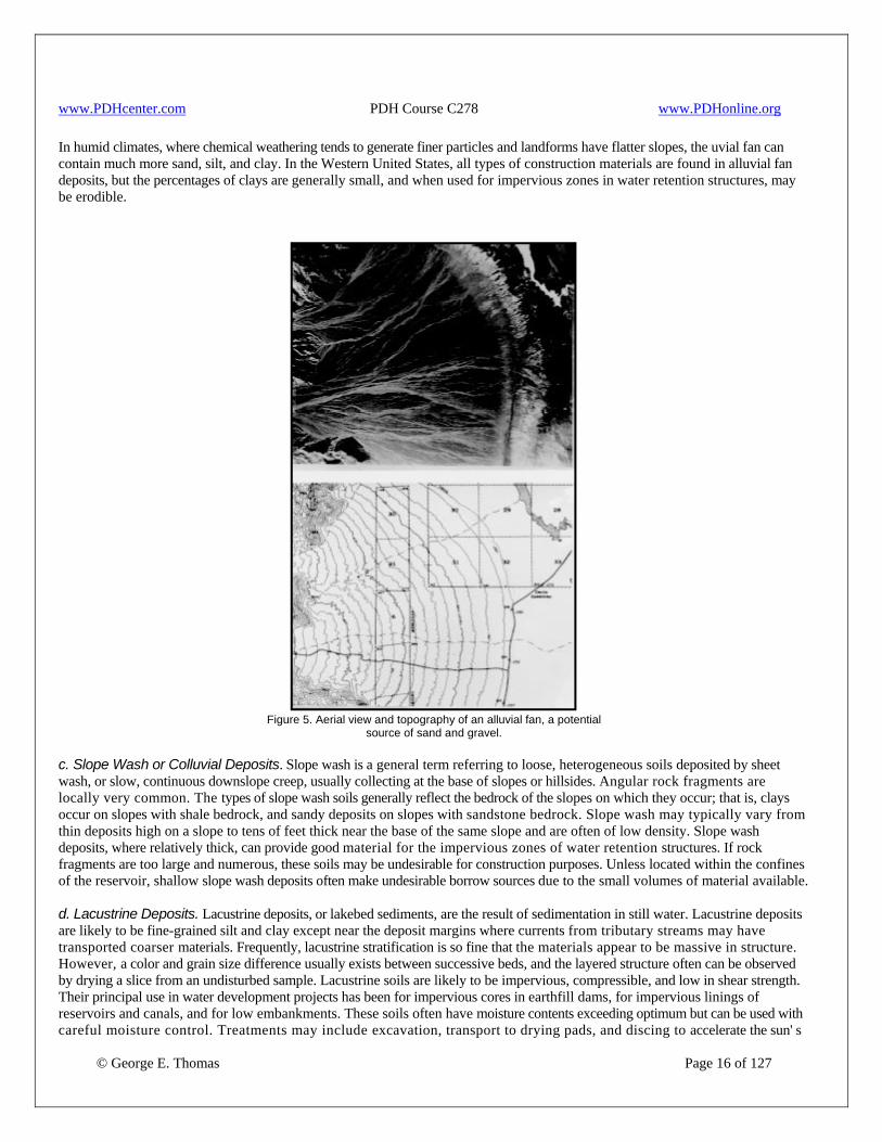
and three levels of gravel terraces. 4. Alluvial Fan Deposits. Alluvial fans are typically gently sloping, fan-shaped masses of soil deposited in locations where an abrupt decrease in stream gradient occurs (see fig. 5). Large alluvial fans, many miles in width and length, occur along mountain fronts, where steep streams from mountain drainages spread out on relatively flat valley floors. Aggrading stream channels migrate laterally along the surface of the fan as temporary channels are both eroded and filled. Much mixing of the soils may result, and lenticular, poorly to well-graded materials are typical laterally across the fan. In contrast, there is a longitudinal grading from the head to the toe of the fan.
© George E. Thomas Page 15 of 127
Coarser material is deposited first and found on the steeper slopes at the head of the fan, while the finer material is carried to the outer edges. Grading of a fan depends on a combination of source material, water velocity, and slope. In arid climates, where mechanical weathering generates coarser particles with associated steeper slopes, the fans may be composed largely of rock fragments, gravel, sand, and silt. If the source produces fine materials, large deposits of silty sands or sandy silts may occur.
www.PDHcenter.com PDH Course C278 www.PDHonline.org
In humid climates, where chemical weathering tends to generate finer particles and landforms have flatter slopes, the uvial fan can contain much more sand, silt, and clay. In the Western United States, all types of construction materials are found in alluvial fan deposits, but the percentages of clays are generally small, and when used for impervious zones in water retention structures, may be erodible.
Figure 5. Aerial view and topography of an alluvial fan, a potential
source of sand and gravel. c. Slope Wash or Colluvial Deposits. Slope wash is a general term referring to loose, heterogeneous soils deposited by sheet wash, or slow, continuous downslope creep, usually collecting at the base of slopes or hillsides. Angular rock fragments are locally very common. The types of slope wash soils generally reflect the bedrock of the slopes on which they occur; that is, clays occur on slopes with shale bedrock, and sandy deposits on slopes with sandstone bedrock. Slope wash may typically vary from thin deposits high on a slope to tens of feet thick near the base of the same slope and are often of low density. Slope wash deposits, where relatively thick, can provide good material for the impervious zones of water retention structures. If rock fragments are too large and numerous, these soils may be undesirable for construction purposes. Unless located within the confines of the reservoir, shallow slope wash deposits often make undesirable borrow sources due to the small volumes of material available.
© George E. Thomas Page 16 of 127
d. Lacustrine Deposits. Lacustrine deposits, or lakebed sediments, are the result of sedimentation in still water. Lacustrine deposits are likely to be fine-grained silt and clay except near the deposit margins where currents from tributary streams may have transported coarser materials. Frequently, lacustrine stratification is so fine that the materials appear to be massive in structure. However, a color and grain size difference usually exists between successive beds, and the layered structure often can be observed by drying a slice from an undisturbed sample. Lacustrine soils are likely to be impervious, compressible, and low in shear strength. Their principal use in water development projects has been for impervious cores in earthfill dams, for impervious linings of reservoirs and canals, and for low embankments. These soils often have moisture contents exceeding optimum but can be used with careful moisture control. Treatments may include excavation, transport to drying pads, and discing to accelerate the sun' s
www.PDHcenter.com PDH Course C278 www.PDHonline.org
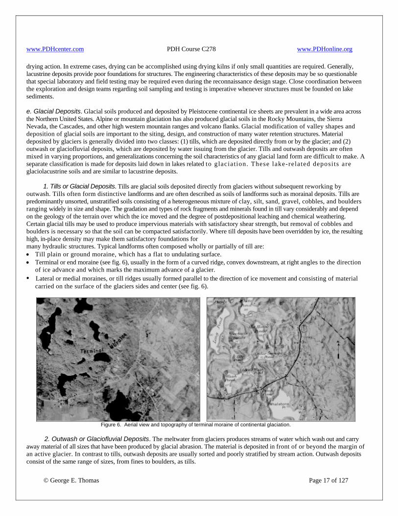
drying action. In extreme cases, drying can be accomplished using drying kilns if only small quantities are required. Generally, lacustrine deposits provide poor foundations for structures. The engineering characteristics of these deposits may be so questionable that special laboratory and field testing may be required even during the reconnaissance design stage. Close coordination between the exploration and design teams regarding soil sampling and testing is imperative whenever structures must be founded on lake sediments. e. Glacial Deposits. Glacial soils produced and deposited by Pleistocene continental ice sheets are prevalent in a wide area across the Northern United States. Alpine or mountain glaciation has also produced glacial soils in the Rocky Mountains, the Sierra Nevada, the Cascades, and other high western mountain ranges and volcano flanks. Glacial modification of valley shapes and deposition of glacial soils are important to the siting, design, and construction of many water retention structures. Material deposited by glaciers is generally divided into two classes: (1) tills, which are deposited directly from or by the glacier; and (2) outwash or glaciofluvial deposits, which are deposited by water issuing from the glacier. Tills and outwash deposits are often mixed in varying proportions, and generalizations concerning the soil characteristics of any glacial land form are difficult to make. A separate classification is made for deposits laid down in lakes related to g laciat ion. These lake-rela ted deposi ts are glaciolacustrine soils and are similar to lacustrine deposits. 1. Tills or Glacial Deposits. Tills are glacial soils deposited directly from glaciers without subsequent reworking by outwash. Tills often form distinctive landforms and are often described as soils of landforms such as morainal deposits. Tills are predominantly unsorted, unstratified soils consisting of a heterogeneous mixture of clay, silt, sand, gravel, cobbles, and boulders ranging widely in size and shape. The gradation and types of rock fragments and minerals found in till vary considerably and depend on the geology of the terrain over which the ice moved and the degree of postdepositional leaching and chemical weathering. Certain glacial tills may be used to produce impervious materials with satisfactory shear strength, but removal of cobbles and boulders is necessary so that the soil can be compacted satisfactorily. Where till deposits have been overridden by ice, the resulting high, in-place density may make them satisfactory foundations for many hydraulic structures. Typical landforms often composed wholly or partially of till are: • Till plain or ground moraine, which has a flat to undulating surface. • Terminal or end moraine (see fig. 6), usually in the form of a curved ridge, convex downstream, at right angles to the direction
of ice advance and which marks the maximum advance of a glacier. • Lateral or medial moraines, or till ridges usually formed parallel to the direction of ice movement and consisting of material
carried on the surface of the glaciers sides and center (see fig. 6).
Figure 6. Aerial view and topography of terminal moraine of continental glaciation.
2. Outwash or Glaciofluvial Deposits. The meltwater from glaciers produces streams of water which wash out and carry away material of all sizes that have been produced by glacial abrasion. The material is deposited in front of or beyond the margin of an active glacier. In contrast to tills, outwash deposits are usually sorted and poorly stratified by stream action. Outwash deposits consist of the same range of sizes, from fines to boulders, as tills.
© George E. Thomas Page 17 of 127
www.PDHcenter.com PDH Course C278 www.PDHonline.org
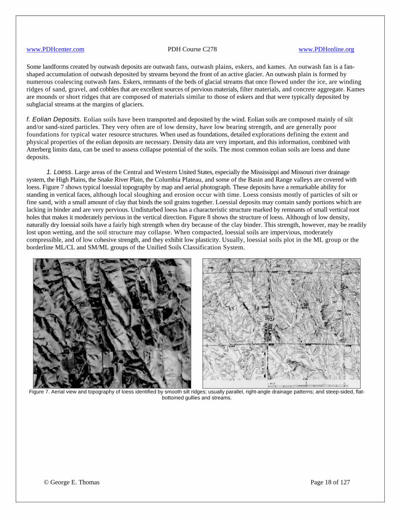
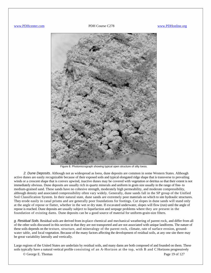
Some landforms created by outwash deposits are outwash fans, outwash plains, eskers, and kames. An outwash fan is a fan-shaped accumulation of outwash deposited by streams beyond the front of an active glacier. An outwash plain is formed by numerous coalescing outwash fans. Eskers, remnants of the beds of glacial streams that once flowed under the ice, are winding ridges of sand, gravel, and cobbles that are excellent sources of pervious materials, filter materials, and concrete aggregate. Kames are mounds or short ridges that are composed of materials similar to those of eskers and that were typically deposited by subglacial streams at the margins of glaciers. f. Eolian Deposits. Eolian soils have been transported and deposited by the wind. Eolian soils are composed mainly of silt and/or sand-sized particles. They very often are of low density, have low bearing strength, and are generally poor foundations for typical water resource structures. When used as foundations, detailed explorations defining the extent and physical properties of the eolian deposits are necessary. Density data are very important, and this information, combined with Atterberg limits data, can be used to assess collapse potential of the soils. The most common eolian soils are loess and dune deposits. 1. Loess. Large areas of the Central and Western United States, especially the Mississippi and Missouri river drainage system, the High Plains, the Snake River Plain, the Columbia Plateau, and some of the Basin and Range valleys are covered with loess. Figure 7 shows typical loessial topography by map and aerial photograph. These deposits have a remarkable ability for standing in vertical faces, although local sloughing and erosion occur with time. Loess consists mostly of particles of silt or fine sand, with a small amount of clay that binds the soil grains together. Loessial deposits may contain sandy portions which are lacking in binder and are very pervious. Undisturbed loess has a characteristic structure marked by remnants of small vertical root holes that makes it moderately pervious in the vertical direction. Figure 8 shows the structure of loess. Although of low density, naturally dry loessial soils have a fairly high strength when dry because of the clay binder. This strength, however, may be readily lost upon wetting, and the soil structure may collapse. When compacted, loessial soils are impervious, moderately compressible, and of low cohesive strength, and they exhibit low plasticity. Usually, loessial soils plot in the ML group or the borderline ML/CL and SM/ML groups of the Unified Soils Classification System.
© George E. Thomas Page 18 of 127
Figure 7. Aerial view and topography of loess identified by smooth silt ridges; usually parallel, right-angle drainage patterns; and steep-sided, flat-bottomed gullies and streams.
www.PDHcenter.com PDH Course C278 www.PDHonline.org
Figure 8. Photomicrograph showing typical open structure of silty loess.
2. Dune Deposits. Although not as widespread as loess, dune deposits are common in some Western States. Although active dunes are easily recognizable because of their exposed soils and typical elongated ridge shape that is transverse to prevailing winds or a crescent shape that is convex upwind, inactive dunes may be covered with vegetation or detritus so that their extent is not immediately obvious. Dune deposits are usually rich in quartz minerals and uniform in grain size usually in the range of fine- to medium-grained sand. These sands have no cohesive strength, moderately high permeability, and moderate compressibility, although density and associated compressibility often vary widely. Generally, dune sands fall in the SP group of the Unified Soil Classification System. In their natural state, dune sands are extremely poor materials on which to site hydraulic structures. They erode easily in canal prisms and are generally poor foundations for footings. Cut slopes in dune sands will stand only at the angle of repose or flatter, whether in the wet or dry state. If excavated underwater, slopes will flow (run) until the angle of repose is reached. Dune deposits are usually subject to liquefaction and seepage problems where they are present in the foundation of existing dams. Dune deposits can be a good source of material for uniform-grain-size filters. g. Residual Soils. Residual soils are derived from in-place chemical and mechanical weathering of parent rock, and differ from all of the other soils discussed in this section in that they are not transported and are not associated with unique landforms. The nature of these soils depends on the texture, structure, and mineralogy of the parent rock, climate, rate of surface erosion, ground-water table, and local vegetation. Because of the many factors affecting the development of residual soils, at any one site there may be great variability laterally and vertically.
© George E. Thomas Page 19 of 127
Large regions of the United States are underlain by residual soils, and many dams are both composed of and founded on them. These soils typically have a natural vertical profile consisting of an A-Horizon at the top, with B and C Horizons progressively

www.PDHcenter.com PDH Course C278 www.PDHonline.org
© George E. Thomas Page 20 of 127
below. The A-Horizon is usually very thin (a few inches), relatively sandy (clays are moved to the underlying horizon by rainwater percolation), and high in organic material. The B-Horizon is relatively clayey. Its original mineral content, especially the silicate minerals, is highly weathered, and there is no trace of parent rock structures. The C-Horizon contains varying percentages of unweathered mineral grains of the parent rock and shows varying degrees of the parent rock structure. When residual soils are used for the foundations and zones of embankment dams, the designer should consider that the B-Horizon is usually less permeable than the C-Horizon. Failure to take the cutoff trench through the C-Horizon and the use of some C-Horizon material in impermeable zones resulted in seepage both through and under dams. Relict joints, foliation, bedding planes, and faults in C-Horizons have resulted in concentrated seepage with subsequent foundation piping. These same relict structures may also cause weak, potential failure planes in dam foundations. Because the type of parent rock has a pronounced influence on the character of residual soils, the rock type should always be determined. The degree to which alteration has progressed largely governs strength characteristics. Laboratory testing, including testing for dispersion, is required if the material appears questionable or when important or large structures are planned. Petrographic analyses for identification of clay minerals in residual soils are required for an understanding of their engineering properties. A distinguishing feature of many residual soils is that individual particles in place are angular but soft. During construction, handling of the material may appreciably reduce the grain size so that the soil, as placed in the structure, may have entirely different characteristics than shown by standard laboratory testing of the original soil. Decomposed granites, which at first appear to be free draining granular materials, may break down when excavated, transported, placed, and compacted. As a result, this material may become semi-pervious to impervious. Special laboratory and field testing programs are often required to determine changes that might occur in the engineering characteristics of residual soils. During this testing, special attention should be paid to soil breakdown by drying, by impact compaction, and by kneading compaction action. Full scale field compaction test sections are sometimes appropriate before proper decisions can be made regarding the use of residual soils. 5. Subsurface Investigations. a. General. Subsurface geotechnical exploration is performed primarily for three purposes: (1) to determine what distinct masses of soil and rock exist in a foundation or borrow area within the area of interest; (2) to determine the dimensions of these bodies; and (3) to determine their engineering properties. In the engineering evaluation of a foundation or borrow area, soil structure should be delineated by means of profiles or plans into a series of masses or zones within which soil properties are relatively uniform. Soils having variable properties can be evaluated, provided the nature of the variation can be defined. Determination of dividing lines between what may be considered uniform soil masses must usually be done on the basis of visual examination and requires considerable judgment. The soil classification system is a satisfactory guide for consideration of soils in a disturbed state. For evaluating soils in the undisturbed state, additional qualifying factors required are in-place water content, density, firmness, and stratification. Color and texture are also helpful in delineating soil masses of uniform characteristics. Occasionally, the only uniformity found in a soil deposit is its heterogeneity. However, by exercising careful analysis, a pattern may be found in the soil mass for use in geotechnical analysis. The dimensions of these masses of soil are determined by methods analogous to those used in surface surveying such as making cross sections or by contouring the upper and lower surfaces (or isopachs). The method used depends somewhat on the type of structure involved. Point structures (buildings) or line structures (canals, pipelines, and roads) are best visualized by cross sections; massive structures (dams) are best visualized by topographic plan maps in addition to cross sections. Unfortunately, the problem of locating measuring points or the "breakpoints" of buried surfaces is difficult because the subsurface cannot be seen, and the cost of investigating the entire area with a grid of test holes is usually great. The normal procedure used for an investigation is to begin with an estimation of the breakpoints' locations based on a geologic interpretation of the subsurface. An initial series of test borings supplemented by data from geophysical surveys, can be used for preliminary delineation of buried surfaces. Breakpoint locations can be further defined by locating additional test borings using successive approximations after considering geophysical data. A grid system of test holes is normally used only on large or critical borrow areas and on foundations (for large earth dams) where subsurface irregularities cannot be established by other means. Simple, inexpensive
www.PDHcenter.com PDH Course C278 www.PDHonline.org
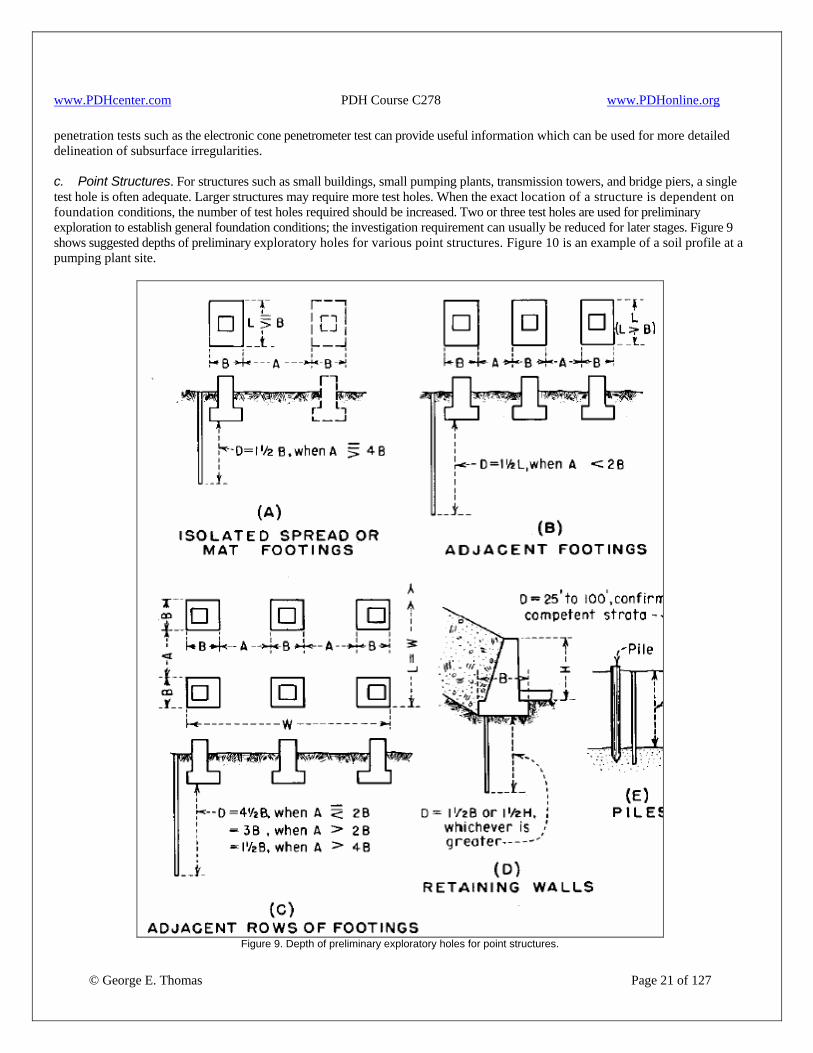
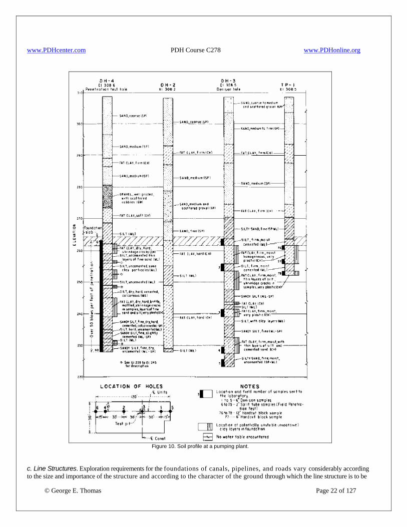
penetration tests such as the electronic cone penetrometer test can provide useful information which can be used for more detailed delineation of subsurface irregularities. c. Point Structures. For structures such as small buildings, small pumping plants, transmission towers, and bridge piers, a single test hole is often adequate. Larger structures may require more test holes. When the exact location of a structure is dependent on foundation conditions, the number of test holes required should be increased. Two or three test holes are used for preliminary exploration to establish general foundation conditions; the investigation requirement can usually be reduced for later stages. Figure 9 shows suggested depths of preliminary exploratory holes for various point structures. Figure 10 is an example of a soil profile at a pumping plant site.
Figure 9. Depth of preliminary exploratory holes for point structures.
© George E. Thomas Page 21 of 127
www.PDHcenter.com PDH Course C278 www.PDHonline.org
Figure 10. Soil profile at a pumping plant.
© George E. Thomas Page 22 of 127
c. Line Structures. Exploration requirements for the foundations of canals, pipelines, and roads vary considerably according to the size and importance of the structure and according to the character of the ground through which the line structure is to be
www.PDHcenter.com PDH Course C278 www.PDHonline.org
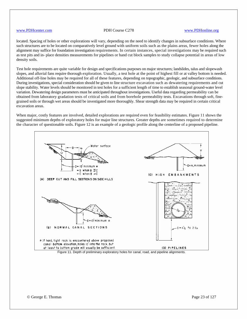
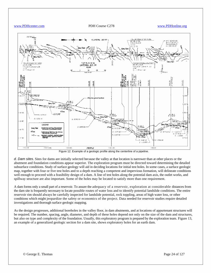
located. Spacing of holes or other explorations will vary, depending on the need to identify changes in subsurface conditions. Where such structures are to be located on comparatively level ground with uniform soils such as the plains areas, fewer holes along the alignment may suffice for foundation investigation requirements. In certain instances, special investigations may be required such as test pits and in- place densities measurements for pipelines or hand cut block samples to study collapse potential in areas of low density soils. Test hole requirements are quite variable for design and specifications purposes on major structures; landslides, talus and slopewash slopes, and alluvial fans require thorough exploration. Usually, a test hole at the point of highest fill or at valley bottom is needed. Additional off-line holes may be required for all of these features, depending on topographic, geologic, and subsurface conditions. During investigations, special consideration should be given to line structure excavation such as dewatering requirements and cut slope stability. Water levels should be monitored in test holes for a sufficient length of time to establish seasonal ground-water level variation. Dewatering design parameters must be anticipated throughout investigations. Useful data regarding permeability can be obtained from laboratory gradation tests of critical soils and from borehole permeability tests. Excavations through soft, fine-grained soils or through wet areas should be investigated more thoroughly. Shear strength data may be required in certain critical excavation areas. When major, costly features are involved, detailed explorations are required even for feasibility estimates. Figure 11 shows the suggested minimum depths of exploratory holes for major line structures. Greater depths are sometimes required to determine the character of questionable soils. Figure 12 is an example of a geologic profile along the centerline of a proposed pipeline.
Figure 11. Depth of preliminary exploratory holes for canal, road, and pipeline alignments.
© George E. Thomas Page 23 of 127
www.PDHcenter.com PDH Course C278 www.PDHonline.org
Figure 12. Example of a geologic profile along the centerline of a pipeline.
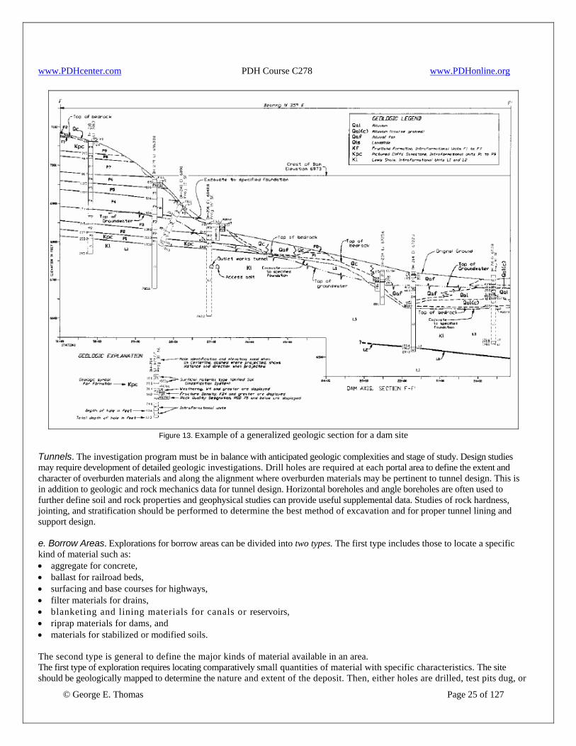
d. Dam sites. Sites for dams are initially selected because the valley at that location is narrower than at other places or the abutment and foundation conditions appear superior. The exploration program must be directed toward determining the detailed subsurface conditions. Study of surface geology will aid in deciding locations for initial test holes. In some cases, a surface geologic map, together with four or five test holes and to a depth reaching a competent and impervious formation, will delineate conditions well enough to proceed with a feasibility design of a dam. A line of test holes along the potential dam axis, the outlet works, and spillway structure are also important. Some of the holes may be located to satisfy more than one requirement. A dam forms only a small part of a reservoir. To assure the adequacy of a reservoir, exploration at considerable distances from the dam site is frequently necessary to locate possible routes of water loss and to identify potential landslide conditions. The entire reservoir rim should always be carefully inspected for landslide potential, rock toppling, areas of high water loss, or other conditions which might jeopardize the safety or economics of the project. Data needed for reservoir studies require detailed investigations and thorough surface geologic mapping. As the design progresses, additional boreholes in the valley floor, in dam abutments, and at locations of appurtenant structures will be required. The number, spacing, angle, diameter, and depth of these holes depend not only on the size of the dam and structures, but also on type and complexity of the foundation. Usually, this exploratory program is prepared by the exploration team. Figure 13, an example of a generalized geologic section for a dam site, shows exploratory holes for an earth dam.
© George E. Thomas Page 24 of 127
www.PDHcenter.com PDH Course C278 www.PDHonline.org
Figure 13. Example of a generalized geologic section for a dam site
Tunnels. The investigation program must be in balance with anticipated geologic complexities and stage of study. Design studies may require development of detailed geologic investigations. Drill holes are required at each portal area to define the extent and character of overburden materials and along the alignment where overburden materials may be pertinent to tunnel design. This is in addition to geologic and rock mechanics data for tunnel design. Horizontal boreholes and angle boreholes are often used to further define soil and rock properties and geophysical studies can provide useful supplemental data. Studies of rock hardness, jointing, and stratification should be performed to determine the best method of excavation and for proper tunnel lining and support design. e. Borrow Areas. Explorations for borrow areas can be divided into two types. The first type includes those to locate a specific kind of material such as: • aggregate for concrete, • ballast for railroad beds, • surfacing and base courses for highways, • filter materials for drains, • blanketing and lining materials for canals or reservoirs, • riprap materials for dams, and • materials for stabilized or modified soils. The second type is general to define the major kinds of material available in an area.
© George E. Thomas Page 25 of 127
The first type of exploration requires locating comparatively small quantities of material with specific characteristics. The site should be geologically mapped to determine the nature and extent of the deposit. Then, either holes are drilled, test pits dug, or

www.PDHcenter.com PDH Course C278 www.PDHonline.org
© George E. Thomas Page 26 of 127
other investigations are performed in highly probable locations to establish if materials exist with the required characteristics. When a potential source is located, supplementary exploration is done to evaluate the required quantity. This should include at least one test pit to confirm drill hole data. The limits of the entire deposit need not be determined; but when exploring for specific materials for a major specification, an excess of the required quantity is needed to provide for waste, shrink, swell, or other unforeseen conditions. The second type of exploration is performed to locate comparatively large quantities of material in which accessibility, uniformity, and workability are as important as engineering properties. A potential source satisfying these requirements is first located on the basis of surface indications. Next, a few holes are drilled or other investigations are performed to establish that appreciable depth of material exists; then the area is explored using a grid of holes or other investigations to establish the volume available. This should include at least one test pit to confirm drill hole data. The grid system layout should provide maximum information with the least number of holes. Normally for a long, narrow deposit, the section lines across the deposit can be located quite far apart, but the holes on these sections should be spaced quite closely. In a valley, more continuity is likely in the longitudinal direction than across the valley; exploring this variability is important. The variability of the deposit will also influence the number of holes. Test pits and test trenches should always be a part of an investigation as they allow for: • Visual inspection of in-place conditions, • Verification of data obtained from drill holes or other investigations, and • Determination of in-place density to evaluate shrink and swell factors. Additional test holes should be required during construction. Prior to actual excavation, sometimes test hole spacing is reduced to 50’ or 100’ near the edges of a deposit and in deposits where material is variable. Figure 14, an example of a plan and sections, shows exploration in a borrow area. On canal work, borrow material is usually taken from areas adjacent to the canal; and test holes or other investigations for borrow are not required if canal alignment test holes are spaced closely enough to ensure availability of satisfactory materials.
g. Selection of Samples. Laboratory or field tests to establish engineering properties of a soil deposit may be required on: (1) soil samples without regard to their in-place condition in the deposit, (2) soil samples in which the natural in-place conditions are preserved as well as possible, and (3) soils as they exist in foundations. Laboratory and field tests are made on soils to determine both the average engineering properties and the range over which these properties vary. Because of cost, the procedure used is to determine by visual examination those samples likely to have the poorest, median, and best engineering properties considered critical. In the specifications stage, index tests are used to select samples for detailed laboratory testing instead of depending on visual examination. During construction, samples are collected from the soils actually used; laboratory tests are performed on a portion of each sample, and the remainder is stored for detailed testing should a need arise. Because samples may become damaged during shipment, storage, or testing, and the exact number to be tested cannot be predetermined, the number of samples collected should be considerably greater than the number actually considered necessary for testing. Disturbed samples are collected when natural in-place conditions of the soil are relatively unimportant, i.e., where the soils will be reworked for use in the structure. The important element in this type of sampling is that: • Samples are uniform throughout the sampling depth interval. • Separate samples are collected for each change in material. • Samples collected are representative of materials being investigated. • Samples collected show lateral and vertical variations in material. If test holes are small, total material is collected from the hole. In large test holes, a uniform cross-section cutting is removed from one wall to provide the samples. In some cases, a specific portion of each stratum is set aside as a representative sample. Normally, all of the initial exploratory holes are sampled completely. If the soil deposits have recognizable uniform characteristics, intermediate holes may not require sampling.
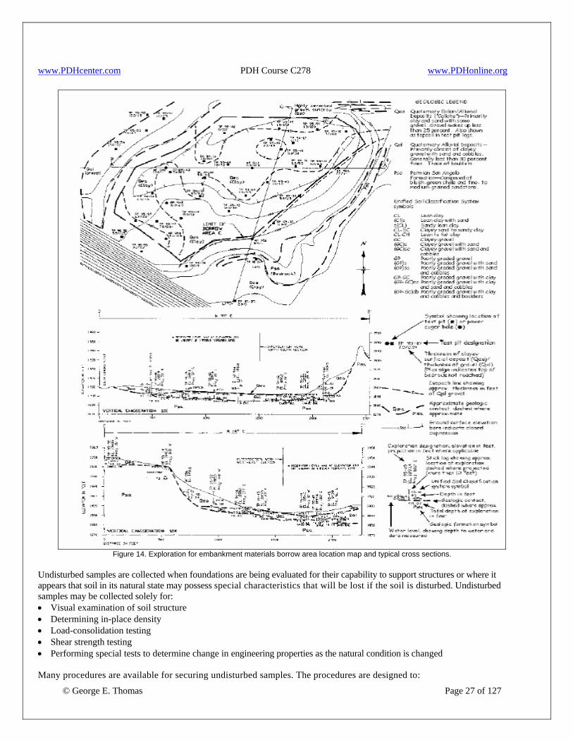
www.PDHcenter.com PDH Course C278 www.PDHonline.org
Figure 14. Exploration for embankment materials borrow area location map and typical cross sections.
Undisturbed samples are collected when foundations are being evaluated for their capability to support structures or where it appears that soil in its natural state may possess special characteristics that will be lost if the soil is disturbed. Undisturbed samples may be collected solely for: • Visual examination of soil structure • Determining in-place density • Load-consolidation testing • Shear strength testing • Performing special tests to determine change in engineering properties as the natural condition is changed
© George E. Thomas Page 27 of 127
Many procedures are available for securing undisturbed samples. The procedures are designed to:
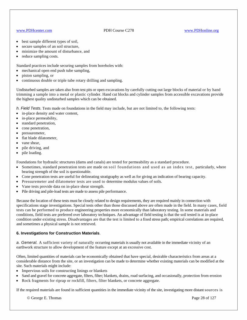
www.PDHcenter.com PDH Course C278 www.PDHonline.org
© George E. Thomas Page 28 of 127
• best sample different types of soil, • secure samples of an soil structure, • minimize the amount of disturbance, and • reduce sampling costs. Standard practices include securing samples from boreholes with: • mechanical open end push tube sampling, • piston sampling, or • continuous double or triple tube rotary drilling and sampling. Undisturbed samples are taken also from test pits or open excavations by carefully cutting out large blocks of material or by hand trimming a sample into a metal or plastic cylinder. Hand cut blocks and cylinder samples from accessible excavations provide the highest quality undisturbed samples which can be obtained. h. Field Tests. Tests made on foundations in the field may include, but are not limited to, the following tests: • in-place density and water content, • in-place permeability, • standard penetration, • cone penetration, • pressuremeter, • flat blade dilatometer, • vane shear, • pile driving, and • pile loading. Foundations for hydraulic structures (dams and canals) are tested for permeability as a standard procedure. • Sometimes, standard penetration tests are made on soi l foundat ions and used as an index test , particularly, where
bearing strength of the soil is questionable. • Cone penetration tests are useful for delineating stratigraphy as well as for giving an indication of bearing capacity. • Pressuremeter and dilatometer tests are used to determine modulus values of soils. • Vane tests provide data on in-place shear strength. • Pile driving and pile-load tests are made to assess pile performance. Because the location of these tests must be closely related to design requirements, they are required mainly in connection with specifications stage investigations. Special tests other than those discussed above are often made in the field. In many cases, field tests can be performed to produce engineering properties more economically than laboratory testing. In some materials and conditions, field tests are preferred over laboratory techniques. An advantage of field testing is that the soil tested is at in-place condition under existing stress. Disadvantages are that the test is limited to a fixed stress path; empirical correlations are required, and sometimes a physical sample is not retrieved. 6. Investigations for Construction Materials. a. General. A sufficient variety of naturally occurring materials is usually not available in the immediate vicinity of an earthwork structure to allow development of the feature except at an excessive cost. Often, limited quantities of materials can be economically obtained that have special, desirable characteristics from areas at a considerable distance from the site, or an investigation can be made to determine whether existing materials can be modified at the site. Such materials might include: • Impervious soils for constructing linings or blankets • Sand and gravel for concrete aggregate, filters, filter; blankets, drains, road surfacing, and occasionally, protection from erosion • Rock fragments for riprap or rockfill, filters, filter blankets, or concrete aggregate. If the required materials are found in sufficient quantities in the immediate vicinity of the site, investigating more distant sources is

www.PDHcenter.com PDH Course C278 www.PDHonline.org
© George E. Thomas Page 29 of 127
unnecessary. If there is a deficiency of impervious materials, pervious materials, or rock in the immediate area, limited quantities of that deficient material may come from 25 to 50 mi distant. Past cases have shown that securing riprap (rock) 200 mi or more distant may be economical. If the haul distance to a suitable borrow source exceeds about 20 mi, design concept changes or modifications to available materials should be considered. Some modifications might be: • adding bentonite to sandy soils, • using cutoff walls, or • using soil-cement or precast concrete blocks as alternate methods of slope protection. A engineering use chart provides information on desirability of earth materials for various uses from a quality standpoint as grouped using the Unified Soil Classification System (USCS). Usually, it is infeasible to secure any material having ideal characteristics (including rock); investigators must exercise considerable judgment in selecting material sources. The extent to which desirable characteristics are sought varies according to the purpose for which the material is to be used. In exploiting materials, volume may be substituted for quality to some extent; special processing of nearer sources may be more economical than long hauls. A definite need for and an improvement in the quality of material must exist with increasing distance from the emplacement site to justify long hauls. For distant sources, accessibility and type of available transportation facilities have an important bearing on desirability of the source. b. Impervious Materials. Situations arise where a special source of impervious materials is required, namely, in the construction of canals; dams on pervious foundations; and terminal, equalizing, or regulating reservoirs. When extensive permeable beds are found in the foundations for such structures, investigators must then locate a source of impervious mater ia l . Such mater ia l should be impervious, as compared to foundation soils, to justify using the material, but highly plastic clay materials are seldom desirable or necessary. These impervious soils are applied as blankets or linings over pervious foundations. Hydraulic gradients through the blanket or lining will be high; consequently, it is essential that gradations should satisfy appropriate filter criteria so that piping of fines from the blanket or lining into the more pervious foundation materials is prevented. Piping also may be prevented by use of geotextiles or of soil bedding which meet appropriate filter criteria. The impervious material will be exposed to water in the canal or reservoir and should be capable of resisting erosive forces of flowing water and of waves. The material may be exposed to alternately wet and dry conditions and in some cases to freezing and thawing. Therefore, materials used for exposed linings or blankets should be free of shrinking and swelling characteristics. Special care should be taken to avoid use of dispersive clay soils for any of these purposes. A number of methods can be employed to overcome problems such as by stabilization with lime, cement, or insulation. However, in many cases, costs may increase to a point where bur ied impermeable geomembranes or geocomposites, or other types of linings such as shotcrete with or without geocomposites, compacted soil-cement, or concrete might become competitive alternatives. Blending two different soils together to form a superior blanketing material has been found to be feasible, such as adding bentonite to sands may be practical. 1. Canal Construction. On canal construction, lining is used to reduce water loss. In turn, it conserves a water supply, prevents waterlogging of adjacent lands, or reduces the size of the conveyance system. Because of these considerations, impermeable lining is very desirable; however, thicker linings of soil material of moderately low permeability have been used. Such linings can be protected from erosion water by reducing the water velocity or by providing a protective cover for the soil lining. These linings are made as thin as possible, both to conserve material and to minimize the necessary additional excavation. Consequently, a mixture of coarse material with impervious soil, either blended together or naturally occurring, will provide a material that is both erosion resistant and impervious. When water velocity in a canal is contemplated to be high or the natural soil is to erode easily, investigations for materials for canals should include a source of coarse material for blending or blanketing unless the impervious material already contains an appreciable percentage of coarse particles. 2. Dam Construction. On dam construction, it is seldom possible to significantly reduce reservoir water loss with partial earth blankets; but seepage gradients can be reduced to the point that piping is prevented. Materials for blankets should be highly impervious so their permeability is very low compared to that of the foundation. Resistance to flowing water usually is not critical, but care should be taken that dispersive clay soils are not used for this application. Because erosion from flowing water is not critical, blending requirements need not be anticipated. However, the possibility of the blanket piping into the foundation and the possibility of cracking of material having high shrinkage and swell characteristics must be considered. Investigations may be required to locate a source of blanket material for storage dams; but more often, blankets are needed in connection with diversion dams. The qualifying differences between impervious blanket material for canals and dams as discussed

www.PDHcenter.com PDH Course C278 www.PDHonline.org
© George E. Thomas Page 30 of 127
above should be noted. c. Pervious Materials. Clean sands and gravels are required for: • concrete aggregates, • filter and drainage zones in earth dams, • filters and drains associated with construction of concrete structures, • bedding under riprap on earth dams, • transition zones to prevent piping. Distance from the construction site to areas where investigations are made for locating a supply of pervious materials having special properties will vary depending on the need for such special material. Using naturally occurring materials rather than those that require processing is usually more economical, especially when found near the site. Designs almost always can be made to accommodate pit run materials such as terrace deposits, etc. If quantities are small, materials acquired from developed commercial sources may be more economical. On major projects such as large embankment dams, careful investigations must be performed so appropriate information is obtained for developing pervious borrow materials. A borrow area rarely produces concrete aggregates or filter and drain materials without processing. Processing operations are required to wash, sort, and crush granular materials and are critical to the contractor in sequencing construction events. For example, in a dam, filter and drain material will be in early demand since the downstream base of a dam will require a drainage blanket. In many cases, processing and stockpiling pervious materials may be desirable in the early phase of construction. For all borrow investigations, long, linear test trenches should be excavated, in addition to point explorations such as test pits or auger borings, to gain a better understanding of geologic variability at the site. Trenches in alluvium should be excavated perpendicular to streamflow. Complete trench wall maps should be made, with all pockets and lenses shown, and with geologic interpretations. Special care should be taken to evaluate percentage of fines and their plasticity so formation of clay balls can be avoided during placement of the pervious materials. On major projects as large dams, such volumetric estimates of oversized particles, e.g., cobbles and boulders, should be supplemented with full-scale gradations of representative materials because processing of oversize is crucial to the contractor' s crushing operations. Coarse particles should be examined petrographically, and hardness should be evaluated. Contractors should be supplied with all borrow information that includes summary gradation plots which include comparisons to design gradation requirements. Test pits should be left open for prospective bidders, if possible. Uncertainties in processing borrow materials should be noted in the specifications. 1. Concrete Aggregates. Investigations for concrete aggregates require more information than other pervious materials. Consequently, data from investigations for concrete aggregate also can be used for other purposes, but data from investigations for other purposes are not usually adequate for concrete aggregate investigations. 2. Filters and Drains. Although the quantity of pervious materials required for filters and drains is usually small, quality requirements are high. Filters and drains are used to prevent piping and reduce hydrostatic uplift pressures. Therefore, the material must be free draining, but at the same time must be able to dissipate relatively high hydraulic heads without movement of either the filter material or the protected soil. Often, a single layer of material will be inadequate, and a two-stage filter should be designed. Fine sand, silt, or clay in the pervious material is objectionable; processing by washing or screening is often required to produce acceptable material from most natural deposits. Although grading requirements will be different, filter materials are commonly secured economically from sources acceptable for concrete aggregate. Particle shape of pervious material is not as critical; processed concrete aggregates rejected for shape can usually be used to construct drainage blankets and drains, if suitable gradation and adequate permeability is maintained. However, minerals contained in pervious materials should be evaluated for potential degradation as water percolates through the filter. Likewise, attention should be given to soundness and durability of particles to be sure no significant change occurs in gradation due to particle breakdown as the material is compacted. Quality evaluation tests, similar to those performed on aggregate for concrete, are performed on these materials to evaluate their

www.PDHcenter.com PDH Course C278 www.PDHonline.org
© George E. Thomas Page 31 of 127
durability and suitability as filters or drains. Filter and drain materials must meet filter design criteria. 3. Bedding Under Riprap. Sand and gravel bedding material under riprap should be coarse but still conform to filter criteria in order to perform as a transition between embankment and riprap. Because of this requirement, blanket material is sometimes secured from rock fines resulting from quarrying operations. However, if a coarse gravel deposit can be found within reasonable distance from the damsite, developing the source will usually be economical. Quantity requirements are quite large, and special processing by screening or other means is costly. The principal purpose of this type of blanket is to prevent waves which penetrate the riprap from eroding the underlying embankment. A limited amount of fine material is not objectionable even though some will most likely be lost through erosive wave action. The material should be durable; most fine material found in gravel deposits is ade-quate. However, gravel deposits have been found containing large quantities of unsuitable material. Such deposits include ancient gravel beds often in terraces that have deteriorated by weathering, and talus or slopewash deposits where water action has been insufficient to remove the soft rock. 4. Drainage Blankets. Materials used for drainage blankets within the downstream zones of earth dams should be pervious with respect to both the embankment and foundation soils. The material should not contain appreciable quantities of silt or clay, and the gradation should meet a required filter criteria. Sometimes, the volume of blanket material can substitute for poor quality. If a sufficient quantity can be found close to the point of use, a search for better materials at greater distances may not be warranted. 5. Road Surfacing and Base Course. Materials for road surfacing or base course are sought primarily for strength and durability. The preferred material for surfacing will consist primarily of medium to fine gravel with enough clay to bind the material together and with relatively small amounts of silt and fine sand. Similar material, but without silt or clay, is preferred for base courses. For these materials, when road construction is for replacement requirements of the local highway agency should be determined before making extensive investigations. d. Riprap and Rockfill. 1. General. Rock fragments are required in connection with earthwork structures to protect earth embankments or exposed excavations from the action of water either as waves, turbulent flow, or heavy rainfall. Rock fragments associated with wave action or flowing water protection are called riprap. The term rockfill is commonly applied to the more massive bodies of fill in dam embankments and consists of rock fragments used primarily to provide structural stability. Such rockfills may serve as drainage blankets or blankets under riprap and if the material to be used is adequate for slope protection, a separate requirement for riprap may not be necessary. Material from rock sources should satisfy two main requirements: (1) the rock source should produce rock fragments in suitable sizes according to required use, and (2) the rock fragments should be hard and durable enough to withstand the processes involved in procuring and placing them and to withstand normal weathering processes and other destructive forces associated in the place of use. Specific gravity and density are important attributes although, to some extent, increase in fragment size may be substituted for high density. Suitable substitutes are available for riprap and rockfill blankets such as soil-cement or asphalt for upstream slope protection, and sod cover for downstream slope protection. These alternatives are considered when rock is unavailable or economically prohibitive. 2. Riprap for Earth Dams. Riprap surfaces on earth dams must withstand severe ice and wave action as well as destructive forces associated with temperature changes, which includes freezing and thawing, heating and cooling, and wetting and drying. Securing highly durable material for riprap is important. Laboratory tests such as the "freeze-thaw" test will disclose weaknesses and lack of durability. Durability can be judged by finding locations where the same rock is subjected to similar conditions in other reservoirs, in stream channels, or in other exposures. Figure 15 shows results of a major blast in a riprap quarry which produced rock fragments of the sizes required for a dam constructed in the Western United States. Joint spacing in a rock outcrop will be a determining factor as to whether adequate size fragments can be secured. Old joints that have become cemented but would break apart during excavation should be noted. Because these mechanical weaknesses are often difficult to detect, a blast test should be conducted (fig. 16). When a bedrock exposure containing satisfactory rock is unavailable in the
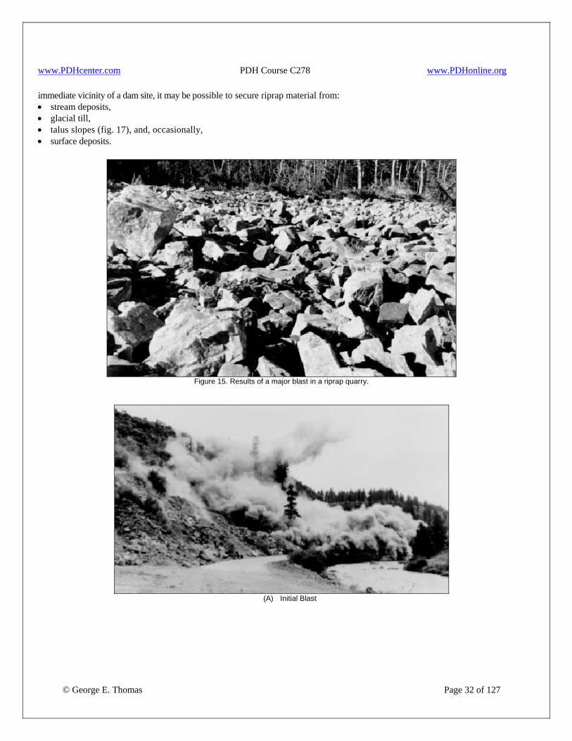
www.PDHcenter.com PDH Course C278 www.PDHonline.org
immediate vicinity of a dam site, it may be possible to secure riprap material from: • stream deposits, • glacial till, • talus slopes (fig. 17), and, occasionally, • surface deposits.
Figure 15. Results of a major blast in a riprap quarry.
© George E. Thomas Page 32 of 127
(A) Initial Blast
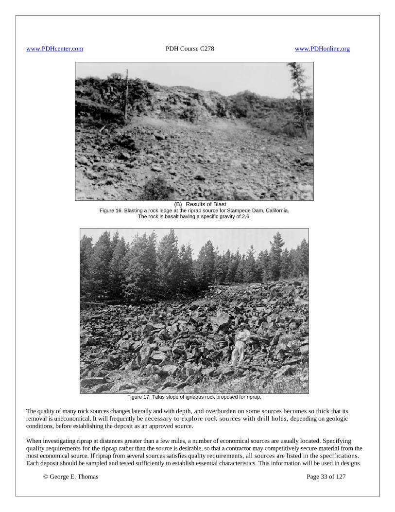
www.PDHcenter.com PDH Course C278 www.PDHonline.org
(B) Results of Blast
Figure 16. Blasting a rock ledge at the riprap source for Stampede Dam, California. The rock is basalt having a specific gravity of 2.6.
Figure 17. Talus slope of igneous rock proposed for riprap.
The quality of many rock sources changes laterally and with depth, and overburden on some sources becomes so thick that its removal is uneconomical. It will frequently be necessary to explore rock sources with drill holes, depending on geologic conditions, before establishing the deposit as an approved source.
© George E. Thomas Page 33 of 127
When investigating riprap at distances greater than a few miles, a number of economical sources are usually located. Specifying quality requirements for the riprap rather than the source is desirable, so that a contractor may competitively secure material from the most economical source. If riprap from several sources satisfies quality requirements, all sources are listed in the specifications. Each deposit should be sampled and tested sufficiently to establish essential characteristics. This information will be used in designs

www.PDHcenter.com PDH Course C278 www.PDHonline.org
© George E. Thomas Page 34 of 127
to establish minimum acceptable properties for specifying quality requirements. Establishment of these minimum requirements will be influenced by: • initial cost, • effective life of the cover, • repair cost, • climatic conditions, and • thickness of cover. 3. Riprap for Stilling Basins. Riprap blankets are commonly used downstream of spillway and outlet works stilling basins, and other energy dissipating structures where high-velocity turbulent flow must be reduced to noneroding velocities. Quantities involved are usually comparatively small, but quality requirements may exceed those of earth dam reservoir riprap blankets. In some instances, even though marginal material may be used on the dam surface, high-quality riprap must be secured for the blanket material used to protect other structures. Where investigations disclose only moderate quality rock in the vicinity of the site, investigations should be extended to establish the location of a high-quality source. 4. Riprap for Canals. Riprap is used in canal construction where severe erosion of the channel could occur. Usually, these locations occur in short reaches of canals below concrete structures, adjacent to bridge piers, and at sharp turns in alignment. Protective requirements vary over a wide range; they may be satisfied with a thin gravel cover or may require riprap equal to that required below the controlling works of dams. When these areas must be protected by riprap, blankets are usually 12” to 24” thick with corresponding rock sizes. 5. Rockfill Blankets. When rockfill is used to provide surface protection from rainfall, almost any rock fragments that do not break down excessively on exposure to air or water are acceptable as rockfill. Shales and some siltstones are about the only types of rock considered unacceptable for this purpose. Size is not critical except that fragments should be at least gravel size, and the upper-size limit is controlled by the specified thickness of the blanket. Rounded gravel, if readily available, is frequently used for this purpose. Special investigations for this type of material are almost wholly confined to the plains areas of the Western United States where rock is generally absent within economical depth beneath ground surface. Substitutes may include sod blankets. Securing rockfill blanket material from appreciable distances is justified only where quality rock is absent in the immediate vicinity of the work and when substitutes are inadequate. 6. Investigative Procedures. Investigation requirements for rock sources for riprap are variable dependent upon: • the stage of investigation, • whether a choice of material is locally available, • the type of specifications to be prepared; i.e., whether contractor or other furnishes the rock. 7. Materials for Stabilized and Modified Soils. a. General. A stabilized soil is a soil whose properties are partially or completely changed by adding a dissimilar material before compacting the soil or by placing an additive into the soil in place. Depending upon the properties and the amount of additive, all of the properties characteristic of the soil may be completely and permanently changed. A modified soil is a soil in which specific properties may be either temporarily or permanently changed. Soils are modified by adding a small amount of an additive before compaction or by placing the additive into the soil in place. Stabilized soils are used as a substitute for: • riprap to protect the upstream slopes of earth dam embankments, • linings for reservoirs, and • temporary protection of construction during river diversion. They are used also as protective blankets and as pipe bedding. Small quantities of additives are used to: • modify and improve properties of soils used in fills, • increase erosion resistance, • reduce permeability, or • provide temporary stability during construction. b. Compacted Soil-Cement. Compacted soil-cement is a stabilized soil consisting of a mixture of soil, cement, and water

www.PDHcenter.com PDH Course C278 www.PDHonline.org
© George E. Thomas Page 35 of 127
compacted to a uniform, dense mass used for linings, protective blankets, and slope protection in lieu of riprap. Placement water content and density are controlled by the laboratory compaction test. The most desirable soil for soil-cement is a silty sand (SM) which has a good distribution of sizes with 15 to 25 percent fines . Other soils may be used; however, more cement may be required to satisfy strength and durability requirements if cleaner, coarse-grained soils are used. Uniformity of soil gradation and moisture when introduced into a continuous feed pugmill type mixing plant is the most important factor in ensuring uniformity of compacted soil-cement. Soil is usually obtained from a borrow area explored in detail to ensure quantity and uniformity desired. A uniform deposit is most desirable. Stratified deposits may be used, provided selective excavation and processing is practical and economical compared to using other potential sources. Selective excavation and mixing during stockpiling may be necessary to provide a soil as uniform in grading and moisture content as practicable. Screening equipment may be necessary to (1) remove undesirable organic material and oversize particles; (2) remove or reduce the size of sand, silt, and clay aggregations, called "clay balls," which tend to form in the borrow areas containing lenses of clay. Laboratory testing is required to determine the quantity and type of cement, the moisture limits, and the compaction requirements to be specif ied for construct ion. Representative samples of the finest, average, and coarsest material should be submitted for laboratory testing. The water proposed for mixing should be reasonably clean and free from organic matter, acids, alkali, salts, oils, and other impurities. Clear water that does not have a saline or brackish taste and is suitable for drinking may be used; however, doubtful sources should be sampled and tested. c. Soil-Cement Slurry. Soil-cement slurry is a cement stabilized soil consisting of a mixture of soil and cement with sufficient water to form a material with the consistency of a thick liquid that will flow easily and can be pumped without segregation. Sands with up to 30-percent nonplastic or slightly plastic fines are best. Soil-cement slurry used for pipe bedding. Even though materials from the trench excavation may be used, locating the borrow areas along the pipeline alignment is generally more economical and usually results in a better controlled and more uniform product. Soil-cement slurry has often been supplied by commercial ready-mix firms when haul distances are economical. d. Modified Soil. A modified soil is a mixture of soil, water, and a small amount of an additive. The various components are well mixed before compaction or added to the soil in place to modify certain properties, temporarily or permanently, to within specified limits. Because of the small amount of additive, a modified soil usually retains most of the characteristics of the original soil because it is an aggregation of uncemented or weakly cemented particles rather than a strongly cemented mass. Limited experience has been acquired on even the most commonly used additives including asphalt, portland cement, fly ash, lime, slag, resins, elastomers, and organic chemicals. As a soil additive, use of lime is the oldest known method of chemical stabilization: it was used by the Romans to construct the Appian Way. Soil-lime is a mixture of soil (usually clay), lime, and water which is compacted to form a dense mass. Experience has shown that mixtures of most clay soils with either quick or hydrated lime and water will form cementitious products in a short period of time. Applications have been limited to use of lime for stabilizing expansive clay soils and dispersive clay soils for water works projects. A canal in California experienced severe damage to both earth and concrete-lined sections from expansive clay soils. Lime, 4 percent by dry mass of soil, was used during rehabilitation of the Canal; and the soil-lime lining has proved durable after more than 20 years of service. Dispersive clay soils will erode in slow-moving or even still water by individual colloidal clay particles going into suspension and then carried away by flowing water. Dispersive clay soils may be made nondispersive by addition of 1 to 4 percent lime by dry mass of soil. Generally, the design lime content is defined as the minimum lime content required to make the soil nondispersive. If lime-treated soil is to be used in surface layers, adding additional lime may be desirable to increase the shrinkage limit to near optimum water content to prevent cracking from drying. In construction specifications, the lime content is often increased 0.5 to 1.0 percent above the design value to account for losses, uneven distribution, incomplete mixing, etc. Dispersive clay soils were found throughout the borrow areas for a Dam in Oklahoma. Lime was used to stabilize those soils for certain critical parts of the dam, and specifications required between 1.5 and 3.0 percent lime to be added to the soil.

www.PDHcenter.com PDH Course C278 www.PDHonline.org
© George E. Thomas Page 36 of 127
B. Exploratory Methods 8. General. Exploration methods may be grouped in different ways: (1) those that produce usable samples and those that do not, and (2) those that are accessible and those that are not. In investigations of foundations or materials, one purpose of an exploration is to secure samples of soil and rock, either for visual examination or for laboratory testing. Procedures which will not produce samples should be used only where the general characteristics of the materials to be penetrated are already known, where sufficient samples have been secured for testing, or where penetration test or other in-place test data can be used to define or refine an investigation plan or program. Sampling methods will vary according to the type of material to be sampled and according to the acceptable degree of sample disturbance; and test holes or other investigations may be advanced by manual labor or by mechanical power. Exploratory holes may be of various sizes depending upon: • the need to access, • the penetration depth, • the size of sample to acquire, and • the type of material to penetrate. Stability of small-size holes entirely above the water table is dependent on the type of material encountered. Holes in soil below the water table usually require support by steel casing, augers, or by drilling fluid. Sometimes, exploratory holes require protection with steel casing because of potential damage to the hole by drilling operations and to prevent contamination of samples with materials from higher elevations. As part of a foundation investigation, many exploratory holes require water testing. When casing is used, specific portions of the foundation may be water tested to simplify evaluation, to concentrate on certain foundation conditions, and to determine required treatment. If water testing or piezometer installation is a part of the requirement, bentonite drilling mud should not be used. In soft or loose soil foundations, the strength of the materials in the wall of the hole may be insufficient to keep soil from flowing into the bottom of the hole. In many instances, just keeping the hole filled with water will suffice to hold materials in place. In severe cases, a wall stabilizer, a heavy fluid, or both must be used. Information on the various stabilizers may be obtained from drilling fluid manufacturers. If water testing is not required, drilling fluid consisting of a mixture of commercially available bentonite or other materials and water may be used. Drilling fluid may be specially prepared to have a required mass per unit volume due to addition of finely divided solid material or to addition of other additives. Samples may be secured from holes supported by drilling fluid or casing with either double-tube or triple-tube soil samplers, core samplers, drive tube, or with push-tube s a m p l e r s . T o m i n i m i z e s a m p l e d i s t u r b a n c e , fixed-piston-type samplers are preferable for very soft soils. The double-tube hollow-stem auger sampler is best for water sensitive, very loose, or unsaturated low density soils. If undisturbed sampling is not successful, a number of in-place tests can be performed that yield valuable information concerning foundation soil conditions. Radiographs (X-ray) may be taken of undisturbed samples after they are received in the laboratory. The radiographs are studied to determine degree of disturbance to each sample. Radiographs are also useful to identify: • slip planes, • fault gouge zones, • slickensides, • contamination by drilling fluid, • amount of slough on top of a sample, • location of gravel particles within a sample, • various other conditions. In drilling exploratory holes through hard materials, where support might normally be unnecessary, crushed zones or faults may be encountered from which rock fragments fall into the hole and either plug the hole, bind the drilling equipment, or both. In such situations, cement grout may be placed in that area; after the grout has set, the hole can be drilled through the grout. Because these crushed zones or faults represent some of the critical conditions being investigated from an engineering standpoint, all pertinent tests (such as water tests) must be performed before grouting the unstable section of hole; a record of the
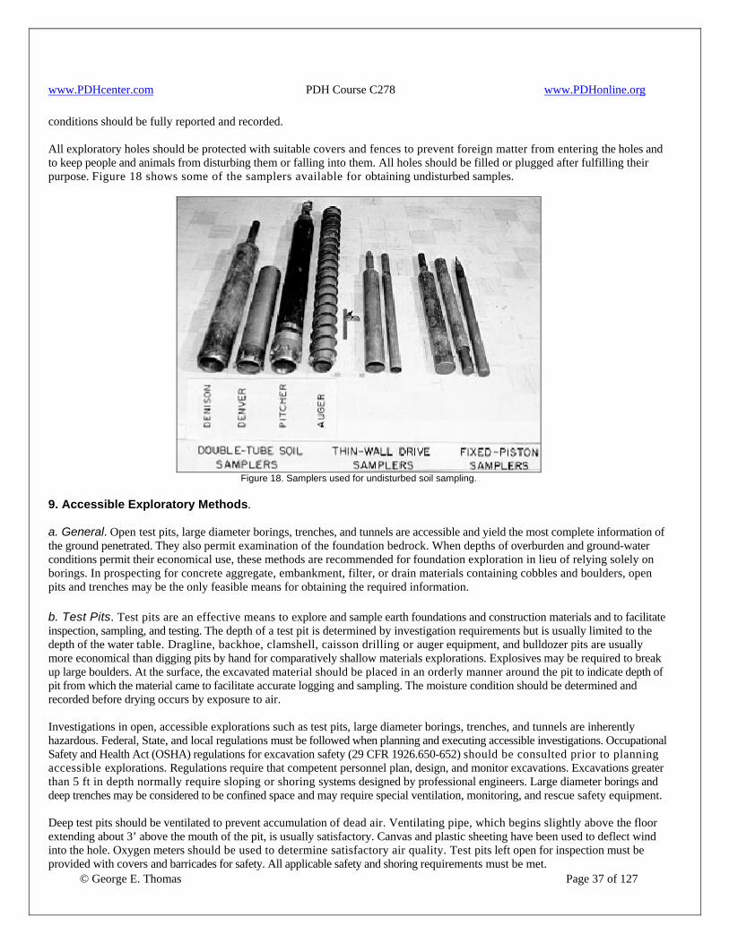
www.PDHcenter.com PDH Course C278 www.PDHonline.org
conditions should be fully reported and recorded. All exploratory holes should be protected with suitable covers and fences to prevent foreign matter from entering the holes and to keep people and animals from disturbing them or falling into them. All holes should be filled or plugged after fulfilling their purpose. Figure 18 shows some of the samplers available for obtaining undisturbed samples.
Figure 18. Samplers used for undisturbed soil sampling.
9. Accessible Exploratory Methods. a. General. Open test pits, large diameter borings, trenches, and tunnels are accessible and yield the most complete information of the ground penetrated. They also permit examination of the foundation bedrock. When depths of overburden and ground-water conditions permit their economical use, these methods are recommended for foundation exploration in lieu of relying solely on borings. In prospecting for concrete aggregate, embankment, filter, or drain materials containing cobbles and boulders, open pits and trenches may be the only feasible means for obtaining the required information. b. Test Pits. Test pits are an effective means to explore and sample earth foundations and construction materials and to facilitate inspection, sampling, and testing. The depth of a test pit is determined by investigation requirements but is usually limited to the depth of the water table. Dragline, backhoe, clamshell, caisson drilling or auger equipment, and bulldozer pits are usually more economical than digging pits by hand for comparatively shallow materials explorations. Explosives may be required to break up large boulders. At the surface, the excavated material should be placed in an orderly manner around the pit to indicate depth of pit from which the material came to facilitate accurate logging and sampling. The moisture condition should be determined and recorded before drying occurs by exposure to air. Investigations in open, accessible explorations such as test pits, large diameter borings, trenches, and tunnels are inherently hazardous. Federal, State, and local regulations must be followed when planning and executing accessible investigations. Occupational Safety and Health Act (OSHA) regulations for excavation safety (29 CFR 1926.650-652) should be consulted prior to planning accessible explorations. Regulations require that competent personnel plan, design, and monitor excavations. Excavations greater than 5 ft in depth normally require sloping or shoring systems designed by professional engineers. Large diameter borings and deep trenches may be considered to be confined space and may require special ventilation, monitoring, and rescue safety equipment.
© George E. Thomas Page 37 of 127
Deep test pits should be ventilated to prevent accumulation of dead air. Ventilating pipe, which begins slightly above the floor extending about 3’ above the mouth of the pit, is usually satisfactory. Canvas and plastic sheeting have been used to deflect wind into the hole. Oxygen meters should be used to determine satisfactory air quality. Test pits left open for inspection must be provided with covers and barricades for safety. All applicable safety and shoring requirements must be met.

www.PDHcenter.com PDH Course C278 www.PDHonline.org
© George E. Thomas Page 38 of 127
When water is encountered in the pit, a pumping system is required for further progress. Small, portable, gasoline-powered, self-priming, centrifugal pumps can be used; however, air or electric powered equipment is preferred whenever possible because of the change of carbon monoxide poisoning. The suction hose should be ½”larger in diameter than the pump discharge and not more than 15’ long. This requires resetting the pump in the pit (on a frame attached to the cribbing) at about 12’intervals. When an air or electric powered pump is not available, and a gasoline engine is used, pipe the exhaust gases well away from the pit when the engine is in or near the pit. When a gasoline engine is operating within a pit, personnel shall not be allowed in the pit for any extended period of time regardless of how well the system is vented. Dewatering test pits is usually expensive and is often unwarranted. c. Large-Diameter Borings. Caisson auger rigs using large-diameter discs, gushers, or buckets are often used when accessible explorations are required to be deeper than about 20’. Depths of over 100’ have been achieved using this method. Wall support must be provided for the total depth. Typical wall support for large-diameter borings may consist of welded steel casing installed after the boring is complete or preformed steel liner plate segments bolted together and placed as the boring progresses. Personnel access within a drilled caisson hole may be provided by an elevator platform rigging using power from a crane hoist or by notched safety rail ladder using an approved grab-ring safety belt. Work may be performed at any depth in the drilled caisson boring using steel platform decking attached to the steel wall support, from steel scaffolding, or from an elevator platform. Access for material logging or sample collection outside a steel-encased caisson hole may be accomplished by cutting openings in the casing at desired locations or by removing bolted liner plate segments to expose the sides of the boring. Sufficient ventilation must be maintained at all times for personnel working within the excavation. Radio communication to surface personnel should be maintained. Water within a drilled excavation may be removed by an electric or air-powered pump with discharge conduit to the surface. Dewatering may require stage pumping by using several holding reservoirs, at appropriate elevations, and additional pumps as required to lift the water from the borehole to the ground surface. Large-diameter borings left open for inspection should always be provided with locking protective covers and should be enclosed by a fence or barricade. d. Trenches. Test trenches are used to provide a continuous exposure of the ground along a given line or section. In general, they serve the same purpose as open test pits but have the added advantage of disclosing the lateral continuity or character of particular strata. They are best suited for shallow exploration (10-15 ft). Trenching can be used to drain wet borrow areas and at the same time fulfill investigation requirements. On a slope, field work consists of excavating an open trench from the top to the bottom to reach representative undisturbed material. Either a single slot trench is excavated down the face of a slope, or a series of short trenches can be spaced at appropriate intervals along the slope. Depending on the extent of investigation required, bulldozers, backhoes, or draglines can be used. Figure 19 shows a trench excavated by bulldozer. All safety procedures and guidelines must be followed when excavating deep trenches to prevent accidents caused by caving ground.
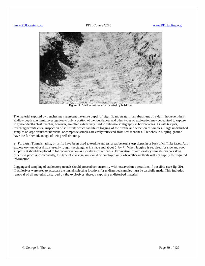
www.PDHcenter.com PDH Course C278 www.PDHonline.org
Figure 19. Shallow test trench excavated by bulldozer.
The material exposed by trenches may represent the entire depth of significant strata in an abutment of a dam; however, their shallow depth may limit investigation to only a portion of the foundation, and other types of exploration may be required to explore to greater depths. Test trenches, however, are often extensively used to delineate stratigraphy in borrow areas. As with test pits, trenching permits visual inspection of soil strata which facilitates logging of the profile and selection of samples. Large undisturbed samples or large disturbed individual or composite samples are easily retrieved from test trenches. Trenches in sloping ground have the further advantage of being self-draining. e. Tunnels. Tunnels, adits, or drifts have been used to explore and test areas beneath steep slopes in or back of cliff like faces. Any exploratory tunnel or drift is usually roughly rectangular in shape and about 5’ by 7’. When lagging is required for side and roof supports, it should be placed to follow excavation as closely as practicable. Excavation of exploratory tunnels can be a slow, expensive process; consequently, this type of investigation should be employed only when other methods will not supply the required information. Logging and sampling of exploratory tunnels should proceed concurrently with excavation operations if possible (see fig. 20). If explosives were used to excavate the tunnel, selecting locations for undisturbed samples must be carefully made. This includes removal of all material disturbed by the explosives, thereby exposing undisturbed material.
© George E. Thomas Page 39 of 127
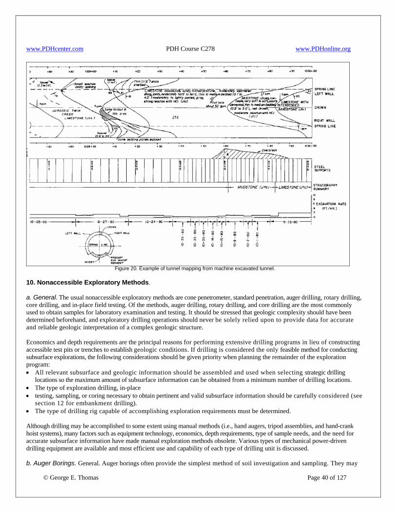
www.PDHcenter.com PDH Course C278 www.PDHonline.org
Figure 20. Example of tunnel mapping from machine excavated tunnel.
10. Nonaccessible Exploratory Methods. a. General. The usual nonaccessible exploratory methods are cone penetrometer, standard penetration, auger drilling, rotary drilling, core drilling, and in-place field testing. Of the methods, auger drilling, rotary drilling, and core drilling are the most commonly used to obtain samples for laboratory examination and testing. It should be stressed that geologic complexity should have been determined beforehand, and exploratory drilling operations should never be solely relied upon to provide data for accurate and reliable geologic interpretation of a complex geologic structure. Economics and depth requirements are the principal reasons for performing extensive drilling programs in lieu of constructing accessible test pits or trenches to establish geologic conditions. If drilling is considered the only feasible method for conducting subsurface explorations, the following considerations should be given priority when planning the remainder of the exploration program: • All relevant subsurface and geologic information should be assembled and used when selecting strategic drilling
locations so the maximum amount of subsurface information can be obtained from a minimum number of drilling locations. • The type of exploration drilling, in-place • testing, sampling, or coring necessary to obtain pertinent and valid subsurface information should be carefully considered (see
section 12 for embankment drilling). • The type of drilling rig capable of accomplishing exploration requirements must be determined. Although drilling may be accomplished to some extent using manual methods (i.e., hand augers, tripod assemblies, and hand-crank hoist systems), many factors such as equipment technology, economics, depth requirements, type of sample needs, and the need for accurate subsurface information have made manual exploration methods obsolete. Various types of mechanical power-driven drilling equipment are available and most efficient use and capability of each type of drilling unit is discussed.
© George E. Thomas Page 40 of 127
b. Auger Borings. General. Auger borings often provide the simplest method of soil investigation and sampling. They may
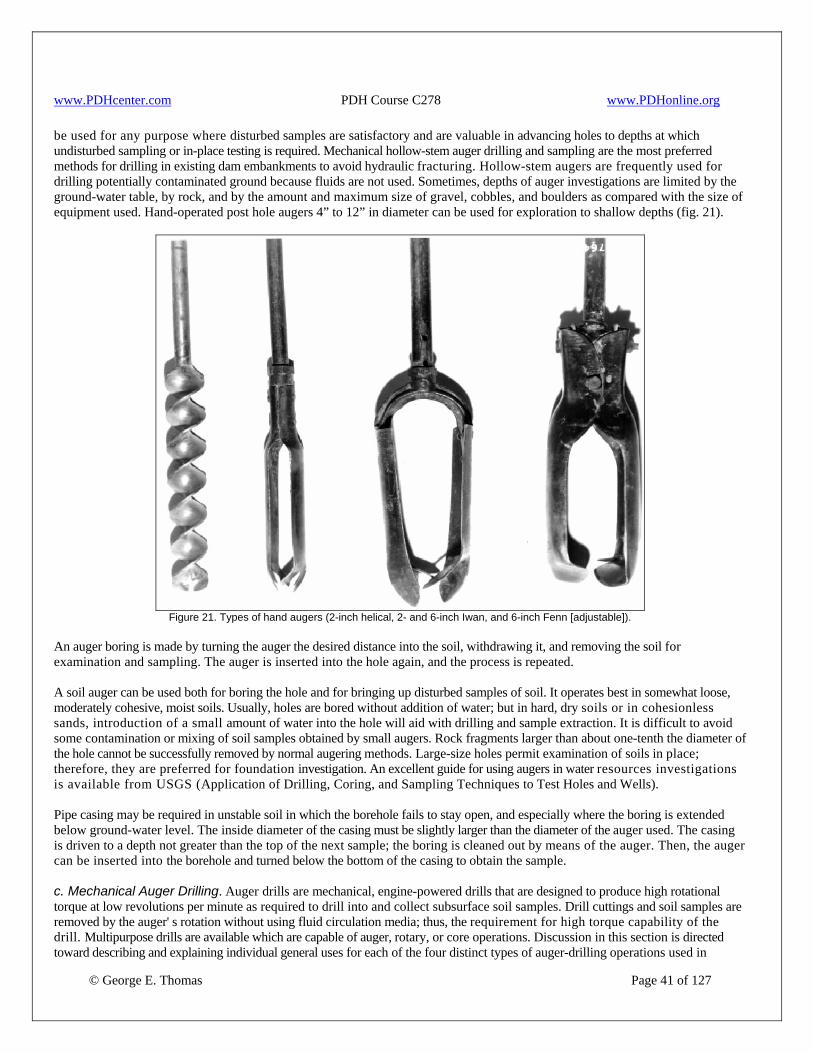
www.PDHcenter.com PDH Course C278 www.PDHonline.org
be used for any purpose where disturbed samples are satisfactory and are valuable in advancing holes to depths at which undisturbed sampling or in-place testing is required. Mechanical hollow-stem auger drilling and sampling are the most preferred methods for drilling in existing dam embankments to avoid hydraulic fracturing. Hollow-stem augers are frequently used for drilling potentially contaminated ground because fluids are not used. Sometimes, depths of auger investigations are limited by the ground-water table, by rock, and by the amount and maximum size of gravel, cobbles, and boulders as compared with the size of equipment used. Hand-operated post hole augers 4” to 12” in diameter can be used for exploration to shallow depths (fig. 21).
Figure 21. Types of hand augers (2-inch helical, 2- and 6-inch Iwan, and 6-inch Fenn [adjustable]).
An auger boring is made by turning the auger the desired distance into the soil, withdrawing it, and removing the soil for examination and sampling. The auger is inserted into the hole again, and the process is repeated. A soil auger can be used both for boring the hole and for bringing up disturbed samples of soil. It operates best in somewhat loose, moderately cohesive, moist soils. Usually, holes are bored without addition of water; but in hard, dry soils or in cohesionless sands, introduction of a small amount of water into the hole will aid with drilling and sample extraction. It is difficult to avoid some contamination or mixing of soil samples obtained by small augers. Rock fragments larger than about one-tenth the diameter of the hole cannot be successfully removed by normal augering methods. Large-size holes permit examination of soils in place; therefore, they are preferred for foundation investigation. An excellent guide for using augers in water resources investigations is available from USGS (Application of Drilling, Coring, and Sampling Techniques to Test Holes and Wells). Pipe casing may be required in unstable soil in which the borehole fails to stay open, and especially where the boring is extended below ground-water level. The inside diameter of the casing must be slightly larger than the diameter of the auger used. The casing is driven to a depth not greater than the top of the next sample; the boring is cleaned out by means of the auger. Then, the auger can be inserted into the borehole and turned below the bottom of the casing to obtain the sample.
© George E. Thomas Page 41 of 127
c. Mechanical Auger Drilling. Auger drills are mechanical, engine-powered drills that are designed to produce high rotational torque at low revolutions per minute as required to drill into and collect subsurface soil samples. Drill cuttings and soil samples are removed by the auger' s rotation without using fluid circulation media; thus, the requirement for high torque capability of the drill. Multipurpose drills are available which are capable of auger, rotary, or core operations. Discussion in this section is directed toward describing and explaining individual general uses for each of the four distinct types of auger-drilling operations used in

www.PDHcenter.com PDH Course C278 www.PDHonline.org
© George E. Thomas Page 42 of 127
subsurface explorations: • Continuous-flight auger drilling • Hollow-stem auger drilling • Helical, disk, and bucket auger drilling • Enclosed augers 1. Continuous-Flight Augers. Continuous-flight auger drilling often provides the simplest and most economical method of subsurface exploration and disturbed sampling of surficial deposits. Flight augers consist of a center drive shaft with spiral-shaped steel flights welded around the outside circumference of the drive shaft. As each auger section is drilled into the ground, another section is added with an identical spiral flight that is manufactured to match the in-hole auger. The joining of each matched auger section results in a continuous spiral flight from the bottom of the hole to the surface. The auger' Rotation causes drill cuttings to move upward along the spiral flights so that disturbed soil samples can be collected at the hole collar. Figure 22 shows a continuous-flight auger drilling operation. Flight augers are manufactured in a wide range of diameters from 2” to greater than 24” . The most common auger used for obtaining disturbed samples of overburden is 6” in diameter. Normally, flight auger depths are limited by: • Equipment torque capability, • ground-water table, • firmness of materials penetrated, • cobble or gravel strata, • caliche zones, and • bedrock. Continuous-flight auger drilling is an economical and highly productive exploration method. A common and efficient use of flight augers is to define borrow area boundaries and depths. Borrow area investigations are conducted by augering holes on a grid pattern to define borrow boundaries and to estimate quantities of usable material. Flight augers are especially efficient when used to collect composite samples of mixed strata material to establish a borrow depth for excavation by belt-loader equipment. Composite samples are collected by advancing auger borings to the depth capability of the belt loader. Hole advancement is accomplished by turning the auger at a low, high-torque rate while adding down pressure for penetration to depth. At the end of the penetration interval, the auger is turned at a higher rate without further downward advancement to collect a composite sample of the material angered through. After the hole is thoroughly cleaned by bringing all cuttings to the surface, the material is mixed to form a representative composite sample and sacked according to requirements for laboratory testing. If additional sample intervals are required, the process can be repeated at a second sample depth. Although the above procedure for collecting composite samples of mixed material strata is efficient, it may not result in an accurate representative sample of the material being drilled, especially at greater depths. This is because the augered material may mix with sidewall material as cuttings are brought to the surface. In addition, auger borings through a noncohesive, low density sand stratum can result in a sample with a greater volume of sand than would be obtained from a borehole having a constant diameter throughout the hole depth. (It is assumed the diameter of the hole enlarges in the sand stratum.) If material contamination is evident or if too large a volume of material is recovered from a given auger penetration interval, a hollow-stem auger with an inner-barrel wire-line system or a continuous-sampler system should be used in lieu of a continuous-flight auger. Other beneficial and efficient uses of flight-auger drilling include: • Delineation of soil properties for lengthy line structures such as canals and pipelines. Economical power auger borings can be spaced in between more detailed sampling and testing locations. • Determination of shallow bedrock depths. This method is especially valuable for estimating overburden excavation
volume required to expose potential rockfill or riprap sources. Confirmation of potential rock quality and usable volume must be determined using rotary core drilling exploration methods.
• Drilling through cohesive soils to install well points to monitor water table fluctuation. This method is recommended for use only through cohesive soils that can be completely removed from the auger hole to leave a clean, full-size open hole so the well point can be installed and backfill material placed.
• Determination of overburden depth to potential sand and gravel deposits for concrete aggregate processing. This method would be used to estimate the volume of overburden excavation required to expose the sand/gravel deposit.
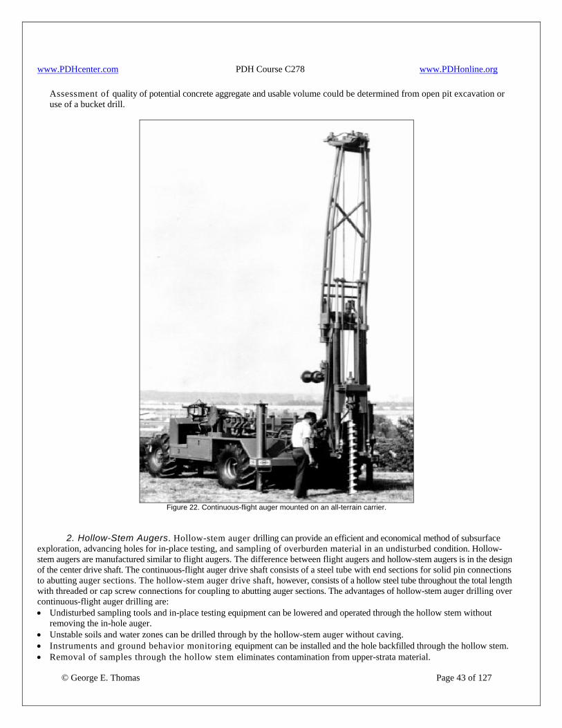
www.PDHcenter.com PDH Course C278 www.PDHonline.org
Assessment of quality of potential concrete aggregate and usable volume could be determined from open pit excavation or use of a bucket drill.
Figure 22. Continuous-flight auger mounted on an all-terrain carrier.
2. Hollow-Stem Augers. Hollow-stem auger drilling can provide an efficient and economical method of subsurface exploration, advancing holes for in-place testing, and sampling of overburden material in an undisturbed condition. Hollow-stem augers are manufactured similar to flight augers. The difference between flight augers and hollow-stem augers is in the design of the center drive shaft. The continuous-flight auger drive shaft consists of a steel tube with end sections for solid pin connections to abutting auger sections. The hollow-stem auger drive shaft, however, consists of a hollow steel tube throughout the total length with threaded or cap screw connections for coupling to abutting auger sections. The advantages of hollow-stem auger drilling over continuous-flight auger drilling are: • Undisturbed sampling tools and in-place testing equipment can be lowered and operated through the hollow stem without
removing the in-hole auger. • Unstable soils and water zones can be drilled through by the hollow-stem auger without caving. • Instruments and ground behavior monitoring equipment can be installed and the hole backfilled through the hollow stem.
© George E. Thomas Page 43 of 127
• Removal of samples through the hollow stem eliminates contamination from upper-strata material.

www.PDHcenter.com PDH Course C278 www.PDHonline.org
© George E. Thomas Page 44 of 127
• The hollow stem may be used as casing so rotary drilling or core drilling operations can be used to advance the hole beyond auger drilling capabilities.
In addition to advantages listed, the hollow-stem auger can function as a continuous-flight auger. This is accomplished by using a plug bit within the center tube of the lead auger, as shown on figure 23. The bit can be retracted at any time for undisturbed sampling or in-place testing without removing the auger tools from the drill hole. In the 1960s, the government developed a double-tube auger to combine soil sampling with auger-hole advancement. This arrangement was quite successful, especially in water sensitive soils such as loess. During the 1980s, auger manufacturers developed (for commercial sale) double-tube auger soil sampling tools so that undisturbed soil samples could be recovered simultaneously with advancement of the hollow-stem auger and without the need for drilling fluids. This development resulted in a method to recover high-quality, undisturbed soil samples of surficial deposits more efficiently and economically than any other method. The method is especially good for sampling low density soils that may be susceptible to collapse upon wetting. Hollow-stem augers are commonly manufactured in 5’ lengths and with sufficient inside clearance to pass sampling or in-place testing tools from 2” to 7” in diameter. The spiral flights are generally sized to auger a hole 4” to 5” larger than the inside diameter of the center tube. Normally, drill depths are limited by: • equipment rotational torque capability, • firmness of materials penetrated, • cobble or gravel strata, • caliche zones, or • bedrock.
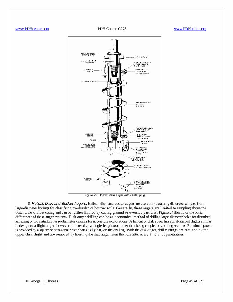
www.PDHcenter.com PDH Course C278 www.PDHonline.org
Figure 23. Hollow stem auger with center plug
3. Helical, Disk, and Bucket Augers. Helical, disk, and bucket augers are useful for obtaining disturbed samples from large-diameter borings for classifying overburden or borrow soils. Generally, these augers are limited to sampling above the water table without casing and can be further limited by caving ground or oversize particles. Figure 24 illustrates the basic differences of these auger systems. Disk-auger drilling can be an economical method of drilling large-diameter holes for disturbed sampling or for installing large-diameter casings for accessible explorations. A helical or disk auger has spiral-shaped flights similar in design to a flight auger; however, it is used as a single-length tool rather than being coupled to abutting sections. Rotational power is provided by a square or hexagonal drive shaft (Kelly bar) on the drill rig. With the disk-auger, drill cuttings are retained by the upper-disk flight and are removed by hoisting the disk auger from the hole after every 3’ to 5’ of penetration.
© George E. Thomas Page 45 of 127
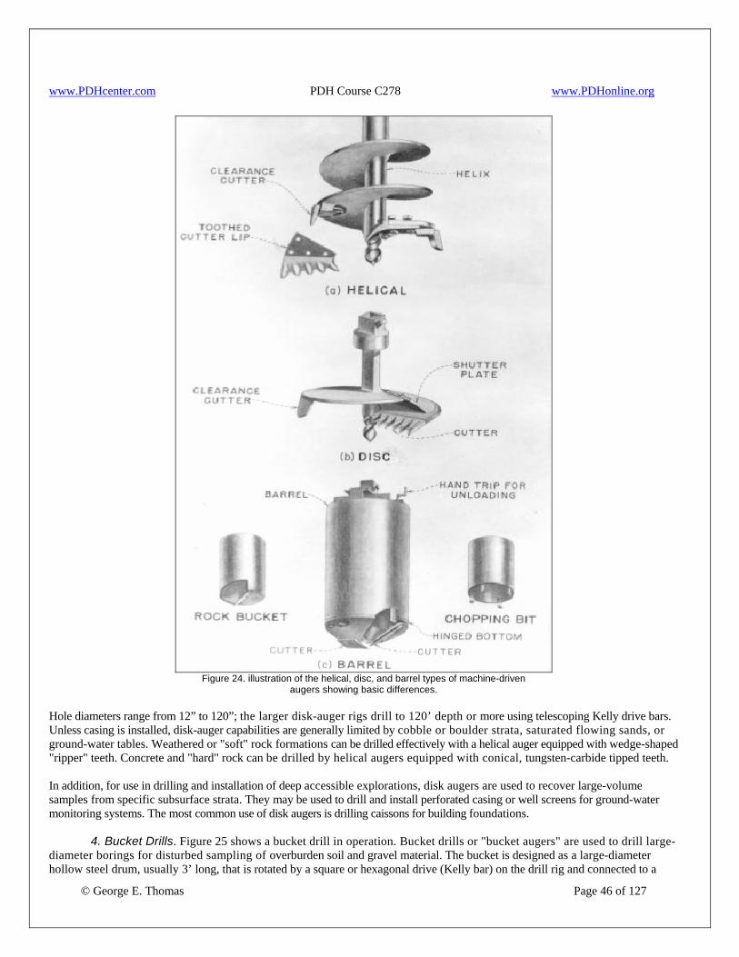
www.PDHcenter.com PDH Course C278 www.PDHonline.org
Figure 24. illustration of the helical, disc, and barrel types of machine-driven
augers showing basic differences. Hole diameters range from 12” to 120”; the larger disk-auger rigs drill to 120’ depth or more using telescoping Kelly drive bars. Unless casing is installed, disk-auger capabilities are generally limited by cobble or boulder strata, saturated flowing sands, or ground-water tables. Weathered or "soft" rock formations can be drilled effectively with a helical auger equipped with wedge-shaped "ripper" teeth. Concrete and "hard" rock can be drilled by helical augers equipped with conical, tungsten-carbide tipped teeth. In addition, for use in drilling and installation of deep accessible explorations, disk augers are used to recover large-volume samples from specific subsurface strata. They may be used to drill and install perforated casing or well screens for ground-water monitoring systems. The most common use of disk augers is drilling caissons for building foundations.
© George E. Thomas Page 46 of 127
4. Bucket Drills. Figure 25 shows a bucket drill in operation. Bucket drills or "bucket augers" are used to drill large-diameter borings for disturbed sampling of overburden soil and gravel material. The bucket is designed as a large-diameter hollow steel drum, usually 3’ long, that is rotated by a square or hexagonal drive (Kelly bar) on the drill rig and connected to a

www.PDHcenter.com PDH Course C278 www.PDHonline.org
steel yoke fixed to the top of the bucket. The bottom of the bucket is designed with a hinged, lockable, steel cutter plate equipped with wedge-shaped ripper teeth. The cutter plate is mechanically locked during the rotational drilling operation and has a 9” to 12” bottom opening through which drill cuttings are forced and collected in the bucket. After about 1.6’ to 3.3’ of drilling penetration, the bucket is hoisted out of the drill hole, attached to a side-jib boom, and moved off the hole to discharge the cuttings. Cuttings are discharged from the bucket by mechanical release of the hinged cutter plate or by opening one side of the bucket, which also may be hinged. The drilling operation is continued by locking the cutter plate or the hinged side panel of the bucket before lowering the bucket to the hole bottom and continuing drilling. Holes can range from 12” to 84” in diameter using a standard bucket. A reamer arm extension, equipped with ripper teeth, can be attached to the bucket drive yoke for overreaming a hole to 120” in diameter using special crane-attached bucket drills. When using overreaming bar extensions drill cuttings enter the bucket from the bottom cutter plate during rotary penetration. Cuttings also fall into the top of the bucket as a result of the rotational cutting action of the overreamer. Generally, bucket drill capabilities are limited by saturated sands, boulders, caliche, or the ground-water table unless casing is installed. Weathered or "soft" rock formations can be effectively penetrated with bucket drills. The larger crane-attached bucket drills have achieved depths of 190’ using telescoping Kelly drive bars and crane draw-works hoist systems. Bucket drills are used for boring caisson holes for foundations. They have proved extremely beneficial for performing subsurface investigations into sand and gravel deposits for concrete aggregate investigations. Also, they may be used to drill and collect intermixed gravel and cobble samples with particle diameters up to about 200 mm (8 in). Bucket drills can be an effective method of drilling deep, accessible, exploration holes. In large caisson applications, the boring can be an "accessible" excavation, as these are often inspected in construction.
© George E. Thomas Page 47 of 127
Figure 25. Bucket drill rig in drilling position with a 24-foot triple Kelly and 36-inch bucket.
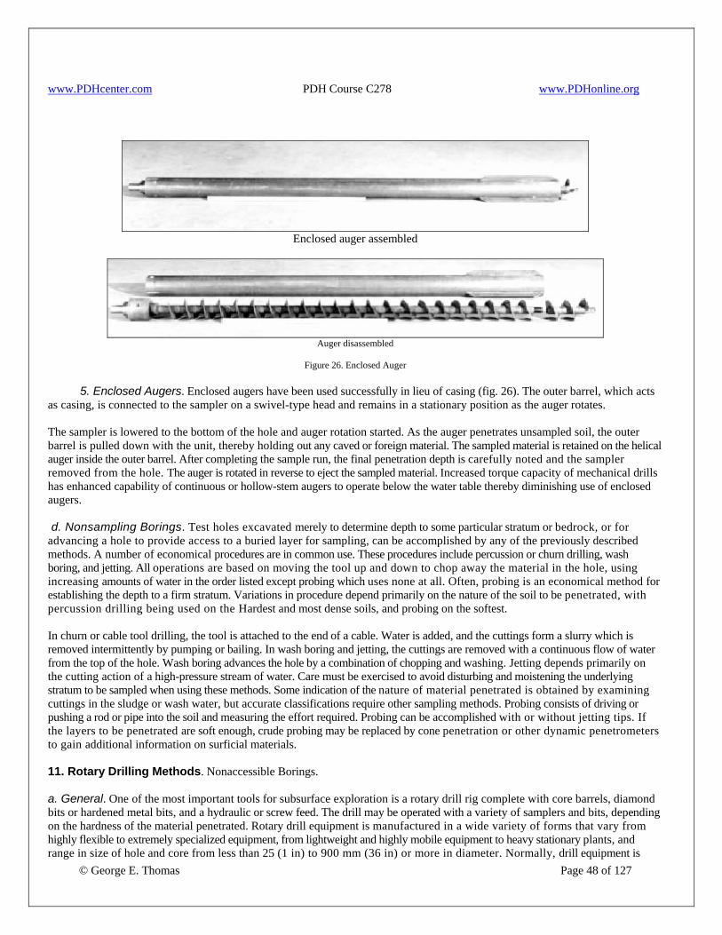
www.PDHcenter.com PDH Course C278 www.PDHonline.org
Enclosed auger assembled
Auger disassembled
Figure 26. Enclosed Auger
5. Enclosed Augers. Enclosed augers have been used successfully in lieu of casing (fig. 26). The outer barrel, which acts as casing, is connected to the sampler on a swivel-type head and remains in a stationary position as the auger rotates.
The sampler is lowered to the bottom of the hole and auger rotation started. As the auger penetrates unsampled soil, the outer barrel is pulled down with the unit, thereby holding out any caved or foreign material. The sampled material is retained on the helical auger inside the outer barrel. After completing the sample run, the final penetration depth is carefully noted and the sampler removed from the hole. The auger is rotated in reverse to eject the sampled material. Increased torque capacity of mechanical drills has enhanced capability of continuous or hollow-stem augers to operate below the water table thereby diminishing use of enclosed augers. d. Nonsampling Borings. Test holes excavated merely to determine depth to some particular stratum or bedrock, or for advancing a hole to provide access to a buried layer for sampling, can be accomplished by any of the previously described methods. A number of economical procedures are in common use. These procedures include percussion or churn drilling, wash boring, and jetting. All operations are based on moving the tool up and down to chop away the material in the hole, using increasing amounts of water in the order listed except probing which uses none at all. Often, probing is an economical method for establishing the depth to a firm stratum. Variations in procedure depend primarily on the nature of the soil to be penetrated, with percussion drilling being used on the Hardest and most dense soils, and probing on the softest. In churn or cable tool drilling, the tool is attached to the end of a cable. Water is added, and the cuttings form a slurry which is removed intermittently by pumping or bailing. In wash boring and jetting, the cuttings are removed with a continuous flow of water from the top of the hole. Wash boring advances the hole by a combination of chopping and washing. Jetting depends primarily on the cutting action of a high-pressure stream of water. Care must be exercised to avoid disturbing and moistening the underlying stratum to be sampled when using these methods. Some indication of the nature of material penetrated is obtained by examining cuttings in the sludge or wash water, but accurate classifications require other sampling methods. Probing consists of driving or pushing a rod or pipe into the soil and measuring the effort required. Probing can be accomplished with or without jetting tips. If the layers to be penetrated are soft enough, crude probing may be replaced by cone penetration or other dynamic penetrometers to gain additional information on surficial materials. 11. Rotary Drilling Methods. Nonaccessible Borings.
© George E. Thomas Page 48 of 127
a. General. One of the most important tools for subsurface exploration is a rotary drill rig complete with core barrels, diamond bits or hardened metal bits, and a hydraulic or screw feed. The drill may be operated with a variety of samplers and bits, depending on the hardness of the material penetrated. Rotary drill equipment is manufactured in a wide variety of forms that vary from highly flexible to extremely specialized equipment, from lightweight and highly mobile equipment to heavy stationary plants, and range in size of hole and core from less than 25 (1 in) to 900 mm (36 in) or more in diameter. Normally, drill equipment is
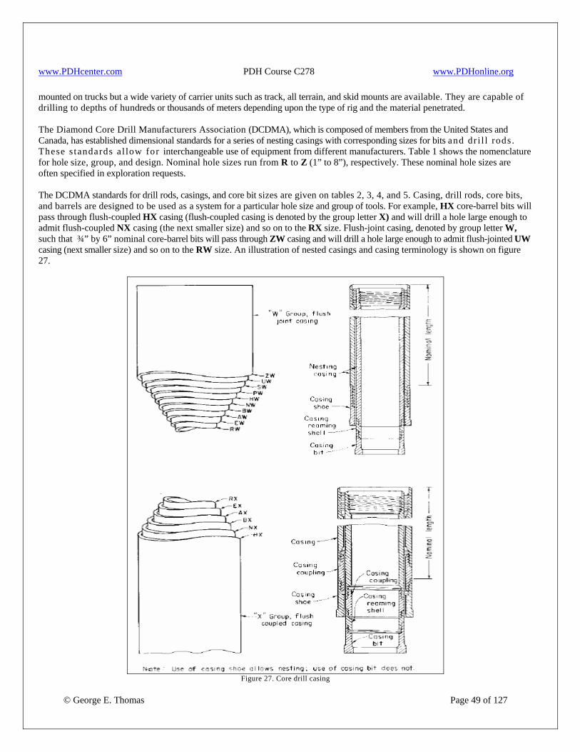
www.PDHcenter.com PDH Course C278 www.PDHonline.org
mounted on trucks but a wide variety of carrier units such as track, all terrain, and skid mounts are available. They are capable of drilling to depths of hundreds or thousands of meters depending upon the type of rig and the material penetrated. The Diamond Core Drill Manufacturers Association (DCDMA), which is composed of members from the United States and Canada, has established dimensional standards for a series of nesting casings with corresponding sizes for bits and dr i l l rods. These s tandards a l low for interchangeable use of equipment from different manufacturers. Table 1 shows the nomenclature for hole size, group, and design. Nominal hole sizes run from R to Z (1” to 8”), respectively. These nominal hole sizes are often specified in exploration requests. The DCDMA standards for drill rods, casings, and core bit sizes are given on tables 2, 3, 4, and 5. Casing, drill rods, core bits, and barrels are designed to be used as a system for a particular hole size and group of tools. For example, HX core-barrel bits will pass through flush-coupled HX casing (flush-coupled casing is denoted by the group letter X) and will drill a hole large enough to admit flush-coupled NX casing (the next smaller size) and so on to the RX size. Flush-joint casing, denoted by group letter W, such that ¾” by 6” nominal core-barrel bits will pass through ZW casing and will drill a hole large enough to admit flush-jointed UW casing (next smaller size) and so on to the RW size. An illustration of nested casings and casing terminology is shown on figure 27.
Figure 27. Core drill casing
© George E. Thomas Page 49 of 127

www.PDHcenter.com PDH Course C278 www.PDHonline.org
© George E. Thomas Page 50 of 127
The straight A through N drill rods with no group designation are no longer commonly used. The recent trend in the drilling industry has been toward the J group of drill rods with taper threads although some W group rods are still frequently used. Wire-line drill rod (casing) sizes are also listed on table 3. Wire-line core barrel systems have not been standardized by DCDMA, but most manufacturers adhere to nominal hole and core sizes listed in the tables. Rotary drills are mechanical and/or hydraulic, engine-powered drills designed for medium rotational torque at variable rotational speeds from low for hole penetration using tricone rock bits or carbide-tipped drag bits to medium-high for undisturbed soil sampling or rock core drilling with core barrels. All rotary drills are equipped with high-pressure fluid injection pumps or air compressors to circulate drill fluid media. These media, which may consist of water, drill mud, compressed air, or air-foam are used to cool and lubricate drill bits and to hold drill cuttings in suspension for circulation to the top of the hole at ground surface. Accessories essential for a drill rig are: • A watermeter • A cathead winch and derrick for driving casing and for hoisting and lowering drill rods • A pump for circulating drilling fluid to the bit and for flushing and water testing the hole • The required driving hammer, bits, drill rods, and core barrels Usually, supported holes are required except when drilling through competent rock or stiff cohesive soils. A short surface casing about 5’ to 10’ long is commonly used at the top of the hole. Use of drilling fluids, including hole wall stabilizer compounds, often nullifies the need for casing in soil, but the foundation cannot be effectively water tested when bentonite drill mud is used. At least two drive hammers should be available, a 140-lbm safety or automatic hammer for standard field penetration tests and a 250 to 400 lbm mass for driving and removing casing pipe. The hammer is raised by pulling tight on an attached rope which is threaded through a sheave at the top of the derrick and wound two to four times on the revolving cathead winch. Sudden loosening of the rope permits the hammer to drop on the driving head attached to the casing. Various types of chopping bits are used to facilitate driving casing through soils containing cobbles and boulders. Large boulders must be drilled with a diamond bit or a roller rock bit or blasted. Casing is raised before blasting. Figure 28 shows a drill rig with derrick. Although the rotary drill was designed primarily for penetrating rock rather than soil, many sample barrels and cutting bits have been developed for investigating a wide variety of soil deposits. Double-tube core barrel samplers of the Denison, Denver, Pitcher, and double-tube auger types are capable of obtaining 6” diameter undisturbed samples of sands, silts, or clays for laboratory testing. The following discussion provides a comprehensive review of rotary drilling equipment technology.
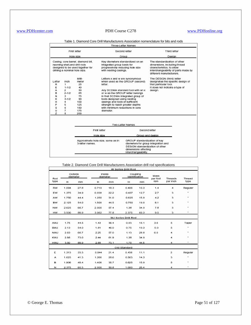
www.PDHcenter.com PDH Course C278 www.PDHonline.org
Table 1. Diamond Core Drill Manufacturers Association nomenclature for bits and rods
Table 2. Diamond Core Drill Manufacturers Association drill rod specifications
© George E. Thomas Page 51 of 127

www.PDHcenter.com PDH Course C278 www.PDHonline.org
Table 3. Wire-line and American Petroleum Institute drill rods
Table 4. Diamond Core Drill manufactures Association casing specifications
© George E. Thomas Page 52 of 127
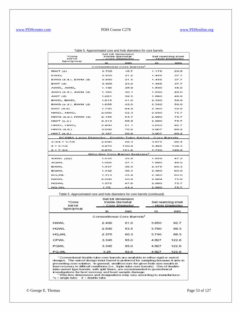
www.PDHcenter.com PDH Course C278 www.PDHonline.org
Table 5. Approximated core and hole diameters for core barrels
Table 5. Approximated core and hole diameters for core barrels (continued)
© George E. Thomas Page 53 of 127
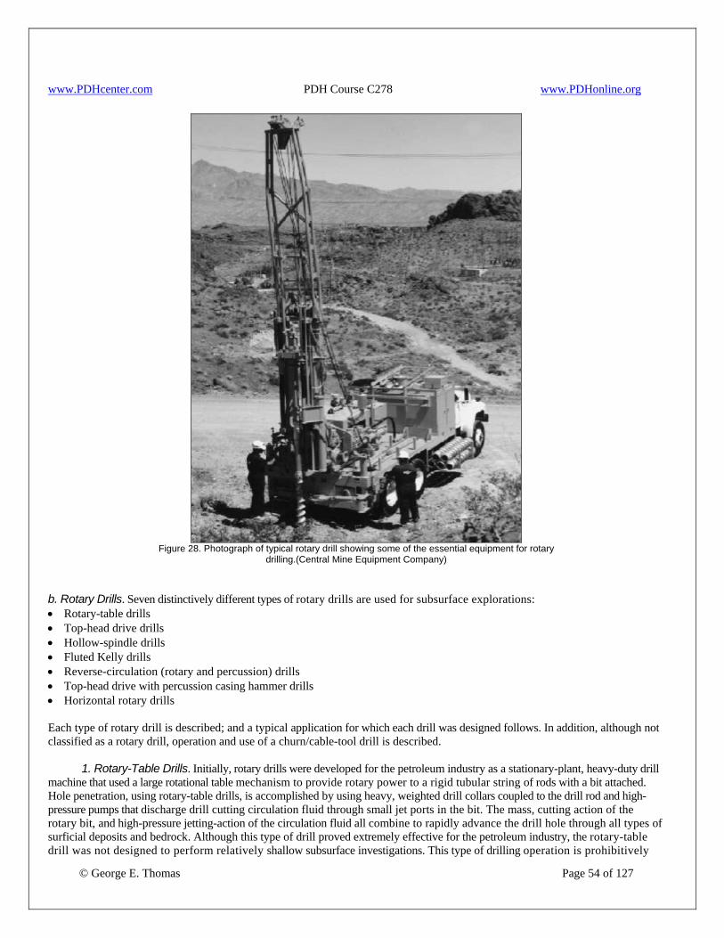
www.PDHcenter.com PDH Course C278 www.PDHonline.org
Figure 28. Photograph of typical rotary drill showing some of the essential equipment for rotary
drilling.(Central Mine Equipment Company) b. Rotary Drills. Seven distinctively different types of rotary drills are used for subsurface explorations: • Rotary-table drills • Top-head drive drills • Hollow-spindle drills • Fluted Kelly drills • Reverse-circulation (rotary and percussion) drills • Top-head drive with percussion casing hammer drills • Horizontal rotary drills Each type of rotary drill is described; and a typical application for which each drill was designed follows. In addition, although not classified as a rotary drill, operation and use of a churn/cable-tool drill is described.
© George E. Thomas Page 54 of 127
1. Rotary-Table Drills. Initially, rotary drills were developed for the petroleum industry as a stationary-plant, heavy-duty drill machine that used a large rotational table mechanism to provide rotary power to a rigid tubular string of rods with a bit attached. Hole penetration, using rotary-table drills, is accomplished by using heavy, weighted drill collars coupled to the drill rod and high-pressure pumps that discharge drill cutting circulation fluid through small jet ports in the bit. The mass, cutting action of the rotary bit, and high-pressure jetting-action of the circulation fluid all combine to rapidly advance the drill hole through all types of surficial deposits and bedrock. Although this type of drill proved extremely effective for the petroleum industry, the rotary-table drill was not designed to perform relatively shallow subsurface investigations. This type of drilling operation is prohibitively

www.PDHcenter.com PDH Course C278 www.PDHonline.org
© George E. Thomas Page 55 of 127
costly for shallow exploration work and results in extremely poor core quality in low-strength rock. A smaller version of the rotary-table drill was developed by drilling rig manufacturers to perform shallow explorations and for water well drilling. These drills are generally truck-mounted rigs with either a chain-driven or gear-driven rotary table. Use of smaller, lower pressure pumps with bypass systems provides better control over downhole fluid pressure that can easily erode or fracture subsurface soil or rock. Mechanical chain pulldowns were added to eliminate use of heavy drill collars and for more precise control over downward bit pressure. However, a drill with a mechanical chain pulldown is not designed with the precision control features necessary to recover high-quality core samples of soil or laminated hard to soft rock. This type of rotary-table drill is used primarily in the water well industry and can be a useful method for installing ground-water monitoring systems. Rotary-table drills can drill holes from 6” to 24” in diameter. Depth capabilities can range from 2,500’ to greater than 10,000’. 2. Top-Head Drive Drills. The top-head drive drill was developed to provide greater operator control over the drilling operation. This is accomplished through use of variable-speed hydraulic pumps and motors to control rotational speed and downward bit pressure. Incorporation of hydraulic systems into drilling machinery vastly improved drilling capabilities, performance, and reliability, with less down time for costly repairs. A skilled operator can precisely control even the largest top-head drive drill by: • Monitoring drill-head hydraulic pressure (indicating bit torque resistance), • Monitoring drill fluid circulation pressure (indicating open-hole, blocked-hole, open-bit, or plugged-bit condition), and • Controlling applied hydraulic pulldown pressure, making it compatible with required bit pressure to drill a given
formation at a constant and efficient rate of penetration. In addition to controlled hydraulic down pressure (crowd pressure), the new top-head drive drill rigs are equipped with "float" controls that provide pulldown pressure equal to the weight of the drill head and in-hole drill tools, and with "hold-back" controls, which apply a back pressure to the down pressure to reduce applied weight at the bit. All of these features make the top-head drive rotary drill one of the most advanced drilling units for high-quality subsurface explorations. Top-head drive rotary drills are generally long-stroke drills capable of a continuous penetration of 10’to 30’ without requiring additional rods or "rechucking." Conventional drilling to advance boreholes to specific depths is normally accomplished using 2- 3/8” to 5-1/2” outside diameter (o.d.) drill rods. For drilling stability, maintenance of hole alignment, and efficient circulation of drill cuttings out of the hole, drill rod diameter should not be less than one-half the diameter of the cutting bit. A drill rod/bit combination of a 4-1/2” o.d. rod and a 8” diameter bit results in a nominal annulus of 1-3/4”between the rod and drill hole wall. This size annulus is adequate for efficient removal of all drill cuttings by high-velocity circulation of drill fluid while maintaining minimum pump pressure. For holes larger than 8’ in diameter, centralizers or stabilizers, about 1” smaller in diameter than the bit should be added to the drill rod string on approximately 30’ centers. These devices stabilize the drill string and aid removal of drill cuttings from the hole through a reduced annulus area. Downhole percussion hammers are commonly used with top-head drive drills for rapid penetration through hard materials and to maintain a better drill-hole alignment than can be achieved with use of tricone rock bits. Tricone rock bits are generally rotated 3 to 4 times faster than a downhole hammer but tend to drift off alignment when one or more cutting cones contact the edge of a boulder or other obstruction. Downhole hammers are operated with air or an air-foam mix as the drilling fluid and are generally rotated between 12 and 20 rpm. The bit is s l ightly concave and embedded with rounded tungsten-carbide buttons that chip away at the rock with the rapid in-out percussion impact blows. The slow rotation and direct impact hit of the single-piece button bit can result in a truer hole alignment than using a 3-roller tricone bit. Under reamer percussion, bits also allow rapid drilling or casing through overburden materials. In subsurface exploration programs, top-head drive drills are commonly used to install ground-water monitoring systems and structural-behavior monitoring instruments. They are used for geothermal investigations, drilling waste injection wells, and to recover large-diameter samples of surficial deposits or rock core. When continuous cores are required, a large-diameter wire-line system should be used to enhance the efficiency of the operation and to eliminate the need for removing all drill rod from the hole for core recovery. In all coring operations using air-foam as the circulation media, the o.d. of the core bit must be sized to drill a hole no less than 7/8” larger in diameter than the o.d. of the drill rod. Water or low-viscosity drill mud circulation could be accomplished with a core bit no less than ½” larger diameter than the o.d. of the rod.

www.PDHcenter.com PDH Course C278 www.PDHonline.org
Hole diameters using top-head drive drills generally range from 6” to 24”; depth capabilities may range from 1,500’ to more than to 5,000’. Figure 29 shows a top-head drive drill with head in mast.
Figure 29. Top-head drive drill with head-in mast for drilling.
3. Hollow-Spindle Drills. The hollow-spindle drill is a multiple-use drill developed for rapid changeover from auger drilling to rotary or core drilling operations. Basically, the hollow-spindle transmits rotary drive power, pull down, and retract to the specific drill tools being used. Unlike other rotary drills designed to drill only with tubular-shaped drill rods or heavy-duty Kelly bars, the hollow-spindle drillhead was designed for attachment of a flight auger or hollow-stem auger drive head. Manual or hydraulically activated chuck assemblies can be used to clamp tubular drill rods, or automatic chuck assemblies for clamping and drilling with fluted Kelly drive bars. Another advantage of a hollow-spindle drill is that the spindle opening provides access for passage of sampling tools or of testing tools through larger-diameter drill rod or through the hollow-stem auger without having to disassemble major equipment. This is especially advantageous with hollow-stem auger drilling, wire-line core drilling, or penetration resistance testing operations. Hollow-spindle drills are manufactured either with variable-speed hydraulic drillheads or mechanically driven drillheads with multiple rotary-speed transmissions. Pulldown feed rate and retraction are hydraulically controlled and can be set to automatically maintain a constant rate of feed and pressure on the drill bit. Hollow-spindle drills are manufactured with capability to drill 6’ to 11’ in a single feed stroke without having to add drill rods or rechuck to achieve additional depth.
© George E. Thomas Page 56 of 127
A wide variety of sampling and in-place testing operations can be performed with a hollow-spindle drill. Disturbed samples can be obtained by flight auger drilling. Undisturbed samples can be obtained using 3” to 5” thinwall push tubes or with soil samplers designed to lock within the hollow-stem auger and simultaneously recover a soil core sample with advancement of the auger. Large-diameter undisturbed soil samples (4” to 6” diameter) can be recovered using drill mud or air-foam circulation media and conventional soil-sampling core barrels. The hollow-spindle design also permits piston sampling of noncohesive sands or

www.PDHcenter.com PDH Course C278 www.PDHonline.org
© George E. Thomas Page 57 of 127
sampling of saturated soils with sampling tools that require an inner rod within the drill rod. Rock coring operations can be performed using wire-line systems or conventional core barrels with water, air, or air-foam circulation media. In-place testing can be conducted from within the hollow-stem auger or casing without major equipment changeover. Specific in-place tests, which can be efficiently performed with a hollow-spindle drill, are vane shear, penetration resistance, flat plate dilatometer, and hydraulic Dutch-cone testing. Hollow-spindle drill holes generally do not exceed 8” in diameter. Depth capabilities vary: • 150’ approximately, through surficial deposits with a hollow-stem auger, • 200’ through surficial deposits with a flight auger, • 800’ through surficial deposits and bedrock with a 6” diameter rotary bit, and • up to 1,000’ through bedrock with a3” diameter wire-line coring system. 4. Fluted Kelly Drills. Figure 30 shows a fluted Kelly drill setup. A rotary drill equipped with a fluted Kelly rod is designed to continuously drill 10’ to 30’ (depends upon length of Kelly rod) without having to add additional drill rods. The Kelly rod is a thick-walled tubular steel rod with 3 or 4 semicircular grooves milled on equally spaced centers into the outer wall of the rod and parallel to the longitudinal axis of the rod. The milled grooves (flutes) run continuously along the total length of the Kelly rod except through the upper and lower tool joint connections. Drills equipped with fluted Kelly rods are generally designed so rotational power is supplied to the Kelly rod through combined use of a stationary drillhead and rotary quill. The quill is equipped with automatic pulldown to apply downward pressure and a Kelly drive bushing for rotational drive to the Kelly rod. The Kelly drive bushing contains hardened steel pins sized to fit into the rod flutes which transmit rotational drive power to the Kelly rod. While rotational torque is being applied by the drive bushing pins within the flute grooves, the Kelly rod has unrestricted up or down movement throughout the total length of the flutes. Hole advancement is accomplished by engaging the automatic pulldown to clamp and apply hydraulically controlled down pressure to the Kelly rod. It is common practice to disengage the automatic pulldown, in relatively easy drilling material, and let the weight of the total drill string (Kelly rod, attached drill rods, and bit) advance the hole with holdback control maintained by braking the draw-works hoist cable attached to the top of the Kelly rod. (Draw works: an oil-well drilling apparatus that consists of a countershaft and drum and that is used for supplying driving power and lifting heavy objects.) Fluted Kelly drills are commonly used for subsurface exploration to bore 6” to 8” diameter holes through surficial deposits and bedrock, to set casing, and to recover large-diameter 4” to 6” undisturbed soil or rock cores with conventional core barrels. Usually, drill mud or air-foam is used to remove cuttings. A fluted Kelly drill is not considered efficient for exploration programs where continuous core recovery is required because they are not generally equipped for wire-line core operations. This limitation significantly reduces coring production because all rods and the core barrel must be removed from the hole after each core run. Fluted Kelly drills are best used for drilling and installing water and/or wells. Hole sizes may be drilled to 12” in diameter and to depths ranging from 1,000’ to 1,500’.
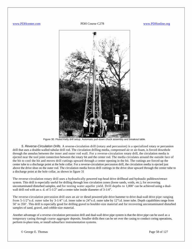
www.PDHcenter.com PDH Course C278 www.PDHonline.org
Figure 30. Fluted Kelly drill setup. Automatic pull-down chuck assembly and breakout table.
5. Reverse-Circulation Drills. A reverse-circulation drill (rotary and percussion) is a specialized rotary or percussion drill that uses a double-walled tubular drill rod. The circulation drilling media, compressed air or air-foam, is forced downhole through the annulus between the inner and outer rod wall. For a reverse-circulation rotary drill, the circulation media is ejected near the tool joint connection between the rotary bit and the center rod. The media circulates around the outside face of the bit to cool the bit and moves drill cuttings upward through a center opening in the bit. The cuttings are forced up the center tube to a discharge point at the hole collar. For a reverse-circulation percussion drill, the circulation media is ejected just above the drive shoe on the outer rod. The circulation media forces drill cuttings in the drive shoe upward through the center tube to a discharge point at the hole collar, as shown in figure 31 The reverse-circulation rotary drill uses a hydraulically powered top-head drive drillhead and hydraulic pulldown/retract system. This drill is especially useful for drilling through loss circulation zones (loose sands, voids, etc.), for recovering uncontaminated disturbed samples, and for testing water aquifer yield. Drill depths to 1,000’ can be achieved using a dual-wall drill rod with an o. d. of 5-1/2” and a center tube inside diameter of 3-1/4”. The reverse-circulation percussion drill uses an air or diesel powered pile drive hammer to drive dual-wall drive pipe ranging from 5-1/2”o.d. outer tube by 3-1/4” i.d. inner tube to 24”o.d. outer tube by 12”i.d. inner tube. Depth capabilities range from 50’ to 350’. This drill is especially good for drilling gravel to boulder-size material and for recovering uncontaminated disturbed samples of sand, gravel, and cobble-size material. Another advantage of a reverse-circulation percussion drill and dual-wall drive pipe system is that the drive pipe can be used as a temporary casing through coarse aggregate deposits. Smaller drills then can be set over the casing to conduct coring operations, perform in-place tests, or install subsurface instrumentation systems.
© George E. Thomas Page 58 of 127
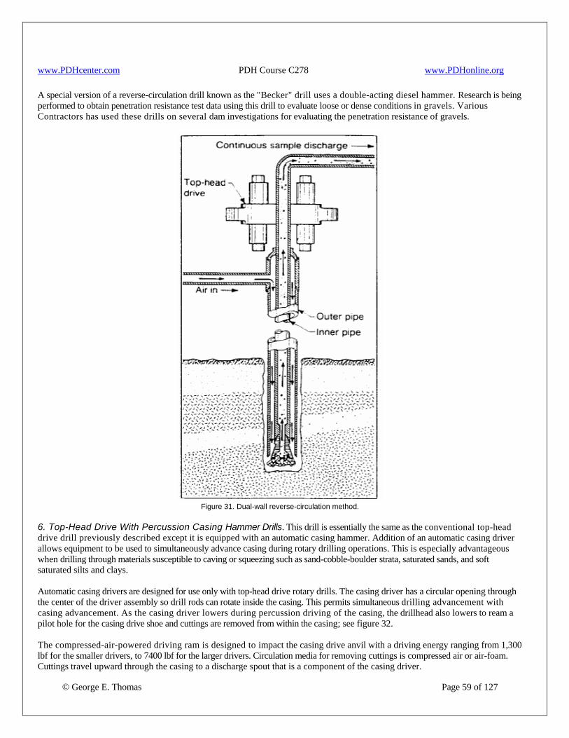
www.PDHcenter.com PDH Course C278 www.PDHonline.org
A special version of a reverse-circulation drill known as the "Becker" drill uses a double-acting diesel hammer. Research is being performed to obtain penetration resistance test data using this drill to evaluate loose or dense conditions in gravels. Various Contractors has used these drills on several dam investigations for evaluating the penetration resistance of gravels.
Figure 31. Dual-wall reverse-circulation method.
6. Top-Head Drive With Percussion Casing Hammer Drills. This drill is essentially the same as the conventional top-head drive drill previously described except it is equipped with an automatic casing hammer. Addition of an automatic casing driver allows equipment to be used to simultaneously advance casing during rotary drilling operations. This is especially advantageous when drilling through materials susceptible to caving or squeezing such as sand-cobble-boulder strata, saturated sands, and soft saturated silts and clays. Automatic casing drivers are designed for use only with top-head drive rotary drills. The casing driver has a circular opening through the center of the driver assembly so drill rods can rotate inside the casing. This permits simultaneous drilling advancement with casing advancement. As the casing driver lowers during percussion driving of the casing, the drillhead also lowers to ream a pilot hole for the casing drive shoe and cuttings are removed from within the casing; see figure 32.
© George E. Thomas Page 59 of 127
The compressed-air-powered driving ram is designed to impact the casing drive anvil with a driving energy ranging from 1,300 lbf for the smaller drivers, to 7400 lbf for the larger drivers. Circulation media for removing cuttings is compressed air or air-foam. Cuttings travel upward through the casing to a discharge spout that is a component of the casing driver.
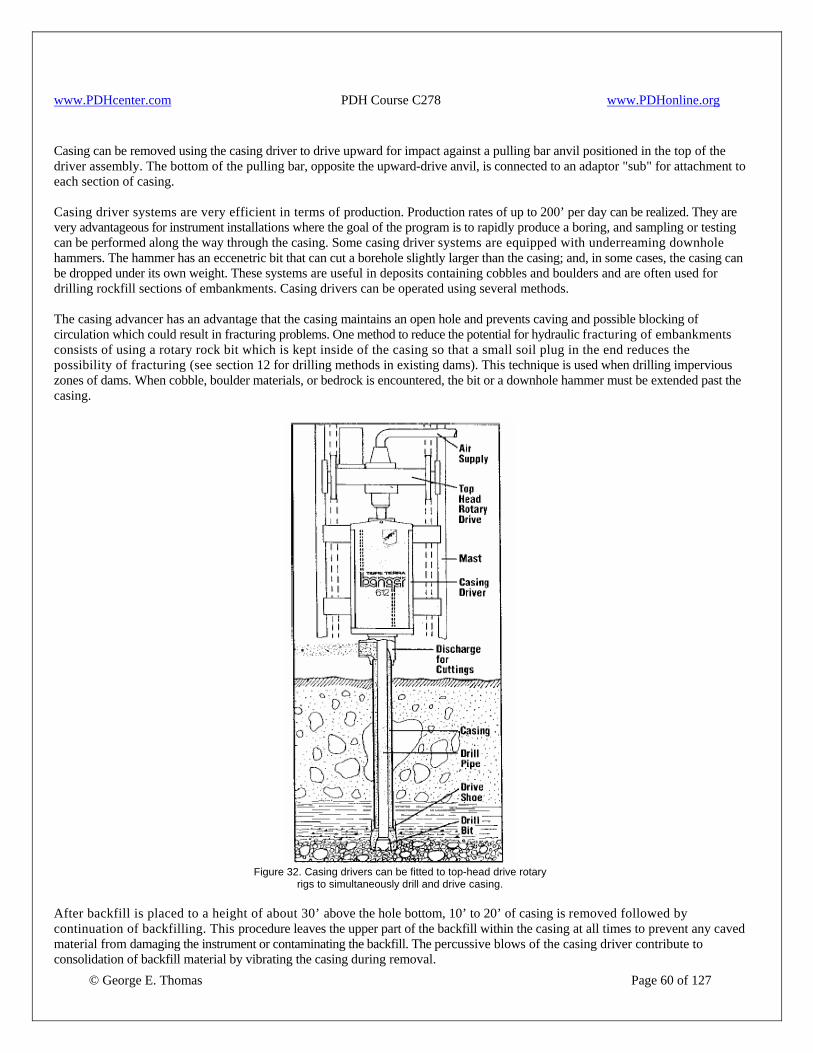
www.PDHcenter.com PDH Course C278 www.PDHonline.org
Casing can be removed using the casing driver to drive upward for impact against a pulling bar anvil positioned in the top of the driver assembly. The bottom of the pulling bar, opposite the upward-drive anvil, is connected to an adaptor "sub" for attachment to each section of casing. Casing driver systems are very efficient in terms of production. Production rates of up to 200’ per day can be realized. They are very advantageous for instrument installations where the goal of the program is to rapidly produce a boring, and sampling or testing can be performed along the way through the casing. Some casing driver systems are equipped with underreaming downhole hammers. The hammer has an eccenetric bit that can cut a borehole slightly larger than the casing; and, in some cases, the casing can be dropped under its own weight. These systems are useful in deposits containing cobbles and boulders and are often used for drilling rockfill sections of embankments. Casing drivers can be operated using several methods. The casing advancer has an advantage that the casing maintains an open hole and prevents caving and possible blocking of circulation which could result in fracturing problems. One method to reduce the potential for hydraulic fracturing of embankments consists of using a rotary rock bit which is kept inside of the casing so that a small soil plug in the end reduces the possibility of fracturing (see section 12 for drilling methods in existing dams). This technique is used when drilling impervious zones of dams. When cobble, boulder materials, or bedrock is encountered, the bit or a downhole hammer must be extended past the casing.
Figure 32. Casing drivers can be fitted to top-head drive rotary
rigs to simultaneously drill and drive casing.
© George E. Thomas Page 60 of 127
After backfill is placed to a height of about 30’ above the hole bottom, 10’ to 20’ of casing is removed followed by continuation of backfilling. This procedure leaves the upper part of the backfill within the casing at all times to prevent any caved material from damaging the instrument or contaminating the backfill. The percussive blows of the casing driver contribute to consolidation of backfill material by vibrating the casing during removal.
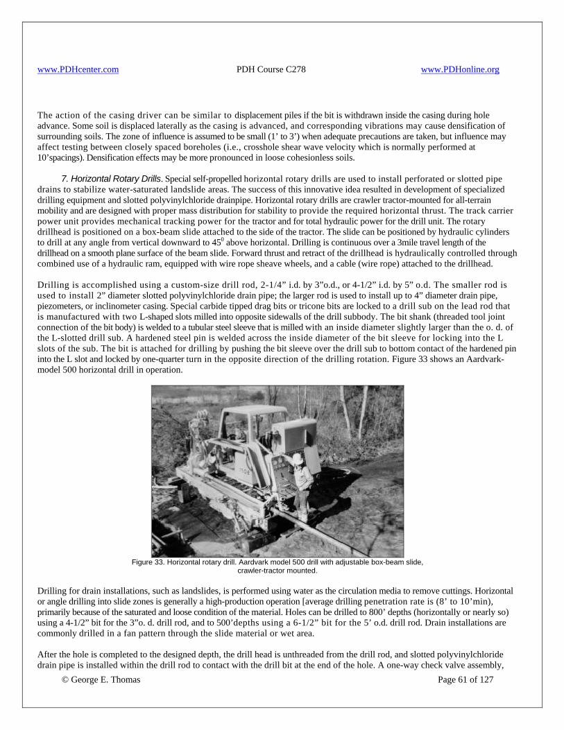
www.PDHcenter.com PDH Course C278 www.PDHonline.org
The action of the casing driver can be similar to displacement piles if the bit is withdrawn inside the casing during hole advance. Some soil is displaced laterally as the casing is advanced, and corresponding vibrations may cause densification of surrounding soils. The zone of influence is assumed to be small (1’ to 3’) when adequate precautions are taken, but influence may affect testing between closely spaced boreholes (i.e., crosshole shear wave velocity which is normally performed at 10’spacings). Densification effects may be more pronounced in loose cohesionless soils. 7. Horizontal Rotary Drills. Special self-propelled horizontal rotary drills are used to install perforated or slotted pipe drains to stabilize water-saturated landslide areas. The success of this innovative idea resulted in development of specialized drilling equipment and slotted polyvinylchloride drainpipe. Horizontal rotary drills are crawler tractor-mounted for all-terrain mobility and are designed with proper mass distribution for stability to provide the required horizontal thrust. The track carrier power unit provides mechanical tracking power for the tractor and for total hydraulic power for the drill unit. The rotary drillhead is positioned on a box-beam slide attached to the side of the tractor. The slide can be positioned by hydraulic cylinders to drill at any angle from vertical downward to 450 above horizontal. Drilling is continuous over a 3mile travel length of the drillhead on a smooth plane surface of the beam slide. Forward thrust and retract of the drillhead is hydraulically controlled through combined use of a hydraulic ram, equipped with wire rope sheave wheels, and a cable (wire rope) attached to the drillhead. Drilling is accomplished using a custom-size drill rod, 2-1/4” i.d. by 3”o.d., or 4-1/2” i.d. by 5” o.d. The smaller rod is used to install 2” diameter slotted polyvinylchloride drain pipe; the larger rod is used to install up to 4” diameter drain pipe, piezometers, or inclinometer casing. Special carbide tipped drag bits or tricone bits are locked to a drill sub on the lead rod that is manufactured with two L-shaped slots milled into opposite sidewalls of the drill subbody. The bit shank (threaded tool joint connection of the bit body) is welded to a tubular steel sleeve that is milled with an inside diameter slightly larger than the o. d. of the L-slotted drill sub. A hardened steel pin is welded across the inside diameter of the bit sleeve for locking into the L slots of the sub. The bit is attached for drilling by pushing the bit sleeve over the drill sub to bottom contact of the hardened pin into the L slot and locked by one-quarter turn in the opposite direction of the drilling rotation. Figure 33 shows an Aardvark- model 500 horizontal drill in operation.
Figure 33. Horizontal rotary drill. Aardvark model 500 drill with adjustable box-beam slide,
crawler-tractor mounted. Drilling for drain installations, such as landslides, is performed using water as the circulation media to remove cuttings. Horizontal or angle drilling into slide zones is generally a high-production operation [average drilling penetration rate is (8’ to 10’min), primarily because of the saturated and loose condition of the material. Holes can be drilled to 800’ depths (horizontally or nearly so) using a 4-1/2” bit for the 3”o. d. drill rod, and to 500’depths using a 6-1/2” bit for the 5’ o.d. drill rod. Drain installations are commonly drilled in a fan pattern through the slide material or wet area.
© George E. Thomas Page 61 of 127
After the hole is completed to the designed depth, the drill head is unthreaded from the drill rod, and slotted polyvinylchloride drain pipe is installed within the drill rod to contact with the drill bit at the end of the hole. A one-way check valve assembly,

www.PDHcenter.com PDH Course C278 www.PDHonline.org
© George E. Thomas Page 62 of 127
positioned behind the discharge ports of the bit, inhibits entrance of ground water or drill cuttings into the rod during drain pipe installation. Drain pipe installation into the drill rod is measured to equal total hole depth plus 3’ to ensure the water discharge point is outside the hole collar. The drill head is power threaded onto the drill rod containing the slotted drain pipe, and an additional 1’ to 1-1/2’ of drilling penetration is made without using circulation media. This operation forces dry cuttings to plug and seize the drill bit so that it can be detached from the drill rod. After the dry drilling, water is pumped into the drill rod to about 300 lbf/in2 pressure behind the plugged bit. A reverse rotation on the drill rod unlocks the expendable bit from the L-slot drill sub. This is followed by a rapid (high power) pullback on the drill rod while monitoring pump pressure for indication of a sudden pressure drop. The pressure drop confirms bit drop off, which is immediately followed by rapid withdrawal of the drill rods. The bit cost is insignificant when compared to cost of removing all drill rods, saving the bit, and attempting to install drain pipe into a hole that has collapsed. As the rods are withdrawn, the drain pipe is maintained in the hole (against the expendable bit) by continuing to inject water against a floating piston device seated against the outlet end of the drain pipe. This floating piston maintains pressure on the drain pipe to prevent withdrawal of the drain during rod removal. After all rods are removed, the drain discharge is plumbed into a manifold pipe assembly and conduit to direct the water away from the slide zone or wet slope area. In addition to drilling for drain installations, horizontal rotary drills have proved extremely efficient and effective for use in performing other types of subsurface work discussed below. Core Drilling for Tunnel Alignment Geology. A river diversion tunnel alignment at a dam in Arizona was horizontally core drilled to a depth of 927’ using a horizontal rotary drill and NWD-3 core-barrel assembly. Core recovery was 98.9 percent. Production rate was good at an average of 26’ per work shift; however, the addition of a pump-in wire-line core barrel would have had the potential to triple conventional core-barrel production. a. Slope Inclinometer Casing Installation. Using a horizontal rotary drill is a productive and efficient method for drilling, installing, and grouting inclinometer casing in place. The drill can be track-walked under its own power to difficult access sites. The inclinometer hole can be drilled with a 6-1/4” expendable bit and a 4-1/4” i.d. drill rod. The inclinometer casing can be installed to the hole bottom through the large-diameter drill rod. After releasing the expendable bit, the annulus between the hole wall and inclinometer casing can be grouted by pumping grout through the drill rod. When grout fills to the hole collar, drill rod can be removed from the hole to complete the inclinometer casing installation. After completion, a water-injection pipe should be lowered to the bottom of the hole inside the inclinometer casing, and clean water should be circulated to remove any grout that may have entered through the casing joints. b. Piezometer Installation. The drilling and installation procedure is the same as that described for an inclinometer casing. However, the backfilling procedure is modified to be compatible with the type of backfill material used. Generally, a uniformly graded clean sand is placed around the piezometer tip or to a specified height above the slot openings of a well screen. This can be accomplished by placing in the drill rod a measured volume of backfill material 1 to 2 ft3 greater than the volume required to fill the hole after removal of a single drill rod. Then, the drill head is threaded onto the collar rod, and one rod is removed while rotating slowly while clean water is simultaneously pumped to force the backfill out of the rod. This procedure leaves 1’ to 2’of material in the bottom rod and protects the piezometer from an open hole condition and possible caving. The backfill and rod removal procedure is repeated in like increments to completion of the hole.
d. Settlement-Plate Monitoring Systems. Choke Canyon Dam, Texas, was constructed with 1-yd2 steel settlement plates embedded at the interface between the embankment and compacted overburden material just below the embankment. After completion of embankment construction, a horizontal rotary drill was set on the 3:1 (horizontal : vertical) downstream slope face to drill and install a steel reinforcement measurement rod to contact on the plate for survey monitoring of embankment settlement. Drilling was conducted using 3”o.d. rod and a 4-1/4” drag bit with water circulation media. The plates were located at six separate stations along the embankment at an average depth of 140’. After the bit contacted each plate, the rods were pulled and the bit removed. The second drill phase was conducted with an open drill sub on the lead rod to contact the steel plate. The 2” diameter casing pipe was lowered through the drill pipe to plate contact. A bentonite seal was injected to the bottom of the hole during removal of a 10’ rod section. The bentonite was used to seal the casing to inhibit grout intrusion. The installation was completed by filling the annulus between the casing and hole wall with grout from the top of the bentonite seal to the hole collar. After removal of all drill rods from the hole and initial grout set, a reinforcement steel rod was installed through the casing to plate contact. The top of the steel rod is a survey point to monitor embankment settlement. e. Churn/Cable-Tool Drills. Although incapable of performing rotary drilling operations, the churn drill or cable tool is

www.PDHcenter.com PDH Course C278 www.PDHonline.org
© George E. Thomas Page 63 of 127
sometimes used in lieu of, or in combination with, rotary or core drills. The churn/cable-tool drilling procedure is one of the oldest known methods of boring holes and continues to be a favored method to drill water wells. Drilling is performed by raising and dropping a heavy string of tools tipped by a blunt-edge chisel bit. The tools are attached to a steel cable that is alternately raised and released for free fall by a powered drum assembly. The cable is suspended from a sheave assembly mounted on an oscillating beam that absorbs the shock load created by quick load release on the taut cable upon impact of the drill tools in the bottom of the hole. The impact of the blunt-edge chisel pulverizes soil and rock material, and the borehole is advanced. The cuttings are suspended in a slurry injected into the borehole. After each 10’ to 20’ penetration, the cable tools are hoisted out of the hole, and a cylindrical bailer equipped with a bottom check valve is lowered into the hole to remove the slurry. This process is repeated to total hole depth. A sampling barrel also can be attached in place of the blunt-edge chisel bit. In this mode, the churn/cable-tool drill can be used to sample and to advance the hole without using water, resulting in a muddy hole. The sampler mode has been used to advantage in sampling glacial terrains where great thicknesses of heterogeneous surficial deposits overlie bedrock. The sampler mode of churn/cable-tool drilling has also been used to advantage for sampling and instrumenting dam embankments. The churn/cable-tool drill is sometimes used to drill and then drive casing pipe through cobble-laden or fractured material so core drilling of deeper formation material can be done with diamond-core drills. When vertical hole alignment is critical, the churn/cable-tool drilling method is very effective. The churn/cable-tool drill was used successfully by the petroleum industry to drill 15” diameter holes to depths of 7,000’. Simplicity of equipment makes churn/cable-tool drilling operations one of the least expensive methods for boring holes. f. Rock Core Drilling. Rock core drilling is accomplished with mechanical, engine-powered rotary drills designed to drill rock and to recover cylindrical cores of rock material. Most core drilling equipment is designed with gear or hydraulically driven variable-speed hollow-spindle rotary drill heads (fig. 34). Average core-diameter capability of these drills ranges from ¾” to 3-3/8” and to 1, 000’depths. Larger-diameter coring operations (4” to 6”) are usually performed using rotary drills, and cores to 6’ in diameter can be drilled and recovered using a shot/calyx drill. A general misconception is that for coring operations with diamond core bits to be efficient, drilling must be performed at the highest rotary speed, regardless of core size. However, this operational procedure usually results only in shortened bit life, poor penetration rate, and excessive vibration that results in broken cores or core blockage. Diamond drill manufacturer’s literature serves as an excellent guide for selecting bit styles and evaluating bit wear. Diamond-core drilling can be compared to using drill presses or center-bore lathes in a machine shop. A small-diameter drill bit must be rotated at high speed with minimum pressure applied to the bit, while a large diameter drill bit must be rotated at a low rate of speed with significant pressure on the bit. Any variation from this procedure results in bit chatter, dulled drill bits, and poor penetration rate. The same is true for a core drilling operation. Rotational speed and "crowd" pressure must be compatible with type and hardness of rock being drilled to achieve a smooth and steady rate of penetration throughout the core length. Any variation results in loss of extremely expensive core bits, poor production, and poor quality core recovery. All core drills are equipped with pumps or compressors to circulate drill media through use of water, drilling mud, air, or air-foam to cool and lubricate the coring bits and to transport the drill cuttings to the top of the hole. Most core drills are equipped with a mast assembly, powered hoist assembly for hoisting heavy loads, and, sometimes, a wire-line hoist assembly for hoisting or lowering a wire-line core barrel through the drill rods. Although some core rigs have been manufactured with gear or chain pulldown/retract systems, precise control over bit pressure can best be accomplished with a hydraulic pulldown/retract system. The hydraulic system must have a precision regulator control so desired pressure can be set and maintained on the bit. Deep-hole rigs should be equipped with a hydraulic holdback control so the full weight of the drill tools is not exerted on the drill bit. Many variations are available in design and mountings for drill rigs manufactured specifically for corin; however, there are only two basic types. They are conventional or wire-line core drills, for drilling and recovering cores up to 6” in diameter, and shot/calyx core drills for drilling, and recovering cores to 6” in diameter.
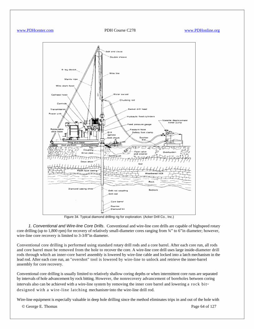
www.PDHcenter.com PDH Course C278 www.PDHonline.org
Figure 34. Typical diamond drilling rig for exploration. (Acker Drill Co., Inc.)
1. Conventional and Wire-line Core Drills. Conventional and wire-line core drills are capable of highspeed rotary core drilling (up to 1,800 rpm) for recovery of relatively small-diameter cores ranging from ¾” to 6”in diameter; however, wire-line core recovery is limited to 3-3/8”in diameter. Conventional core drilling is performed using standard rotary drill rods and a core barrel. After each core run, all rods and core barrel must be removed from the hole to recover the core. A wire-line core drill uses large inside-diameter drill rods through which an inner-core barrel assembly is lowered by wire-line cable and locked into a latch mechanism in the lead rod. After each core run, an "overshot" tool is lowered by wire-line to unlock and retrieve the inner-barrel assembly for core recovery. Conventional core drilling is usually limited to relatively shallow coring depths or when intermittent core runs are separated by intervals of hole advancement by rock bitting. However, the nonrecovery advancement of boreholes between coring intervals also can be achieved with a wire-line system by removing the inner core barrel and lowering a rock bi t-designed with a wire- l ine la tching mechanism-into the wire-line drill rod.
© George E. Thomas Page 64 of 127
Wire-line equipment is especially valuable in deep hole drilling since the method eliminates trips in and out of the hole with
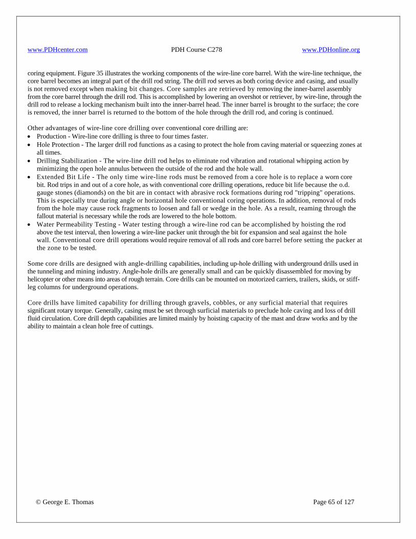
www.PDHcenter.com PDH Course C278 www.PDHonline.org
© George E. Thomas Page 65 of 127
coring equipment. Figure 35 illustrates the working components of the wire-line core barrel. With the wire-line technique, the core barrel becomes an integral part of the drill rod string. The drill rod serves as both coring device and casing, and usually is not removed except when making bit changes. Core samples are retrieved by removing the inner-barrel assembly from the core barrel through the drill rod. This is accomplished by lowering an overshot or retriever, by wire-line, through the drill rod to release a locking mechanism built into the inner-barrel head. The inner barrel is brought to the surface; the core is removed, the inner barrel is returned to the bottom of the hole through the drill rod, and coring is continued. Other advantages of wire-line core drilling over conventional core drilling are: • Production - Wire-line core drilling is three to four times faster. • Hole Protection - The larger drill rod functions as a casing to protect the hole from caving material or squeezing zones at
all times. • Drilling Stabilization - The wire-line drill rod helps to eliminate rod vibration and rotational whipping action by
minimizing the open hole annulus between the outside of the rod and the hole wall. • Extended Bit Life - The only time wire-line rods must be removed from a core hole is to replace a worn core
bit. Rod trips in and out of a core hole, as with conventional core drilling operations, reduce bit life because the o.d. gauge stones (diamonds) on the bit are in contact with abrasive rock formations during rod "tripping" operations. This is especially true during angle or horizontal hole conventional coring operations. In addition, removal of rods from the hole may cause rock fragments to loosen and fall or wedge in the hole. As a result, reaming through the fallout material is necessary while the rods are lowered to the hole bottom.
• Water Permeability Testing - Water testing through a wire-line rod can be accomplished by hoisting the rod above the test interval, then lowering a wire-line packer unit through the bit for expansion and seal against the hole wall. Conventional core drill operations would require removal of all rods and core barrel before setting the packer at the zone to be tested.
Some core drills are designed with angle-drilling capabilities, including up-hole drilling with underground drills used in the tunneling and mining industry. Angle-hole drills are generally small and can be quickly disassembled for moving by helicopter or other means into areas of rough terrain. Core drills can be mounted on motorized carriers, trailers, skids, or stiff-leg columns for underground operations. Core drills have limited capability for drilling through gravels, cobbles, or any surficial material that requires significant rotary torque. Generally, casing must be set through surficial materials to preclude hole caving and loss of drill fluid circulation. Core drill depth capabilities are limited mainly by hoisting capacity of the mast and draw works and by the ability to maintain a clean hole free of cuttings.
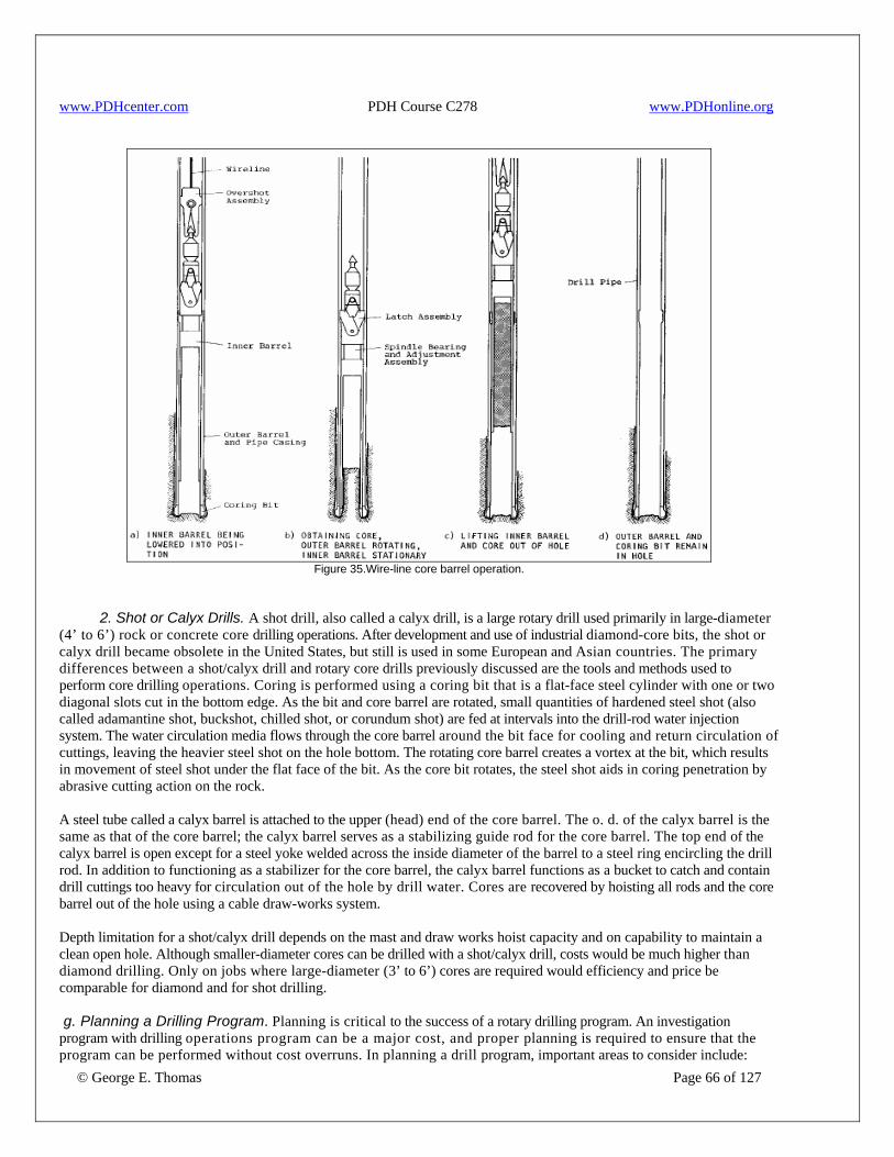
www.PDHcenter.com PDH Course C278 www.PDHonline.org
Figure 35.Wire-line core barrel operation.
2. Shot or Calyx Drills. A shot drill, also called a calyx drill, is a large rotary drill used primarily in large-diameter (4’ to 6’) rock or concrete core drilling operations. After development and use of industrial diamond-core bits, the shot or calyx drill became obsolete in the United States, but still is used in some European and Asian countries. The primary differences between a shot/calyx drill and rotary core drills previously discussed are the tools and methods used to perform core drilling operations. Coring is performed using a coring bit that is a flat-face steel cylinder with one or two diagonal slots cut in the bottom edge. As the bit and core barrel are rotated, small quantities of hardened steel shot (also called adamantine shot, buckshot, chilled shot, or corundum shot) are fed at intervals into the drill-rod water injection system. The water circulation media flows through the core barrel around the bit face for cooling and return circulation of cuttings, leaving the heavier steel shot on the hole bottom. The rotating core barrel creates a vortex at the bit, which results in movement of steel shot under the flat face of the bit. As the core bit rotates, the steel shot aids in coring penetration by abrasive cutting action on the rock. A steel tube called a calyx barrel is attached to the upper (head) end of the core barrel. The o. d. of the calyx barrel is the same as that of the core barrel; the calyx barrel serves as a stabilizing guide rod for the core barrel. The top end of the calyx barrel is open except for a steel yoke welded across the inside diameter of the barrel to a steel ring encircling the drill rod. In addition to functioning as a stabilizer for the core barrel, the calyx barrel functions as a bucket to catch and contain drill cuttings too heavy for circulation out of the hole by drill water. Cores are recovered by hoisting all rods and the core barrel out of the hole using a cable draw-works system. Depth limitation for a shot/calyx drill depends on the mast and draw works hoist capacity and on capability to maintain a clean open hole. Although smaller-diameter cores can be drilled with a shot/calyx drill, costs would be much higher than diamond drilling. Only on jobs where large-diameter (3’ to 6’) cores are required would efficiency and price be comparable for diamond and for shot drilling.
© George E. Thomas Page 66 of 127
g. Planning a Drilling Program. Planning is critical to the success of a rotary drilling program. An investigation program with drilling operations program can be a major cost, and proper planning is required to ensure that the program can be performed without cost overruns. In planning a drill program, important areas to consider include:
www.PDHcenter.com PDH Course C278 www.PDHonline.org
© George E. Thomas Page 67 of 127
• preplanning, • site visit, • topography and accessibility, • protection of the environment, • drilling concerns, • equipment concerns, • traffic control and safety plans, • buried and overhead utilities, • special considerations, and • preparation of drilling specifications. 12. Procedures for Drilling in Embankment Dams. Concern exists throughout the geotechnical community regarding drilling in embankment dams and the potential for hydraulic fracturing of the impervious core during drilling. This concern has prompted an evaluation of conditions and drilling methods which pose the greatest potential for hydraulic fracturing. The following procedures should be followed when drilling in the impervious portions of embankment dams. a. Conditions Conducive to Hydraulic Fracturing. Embankment design and construction practices, historically as well as currently, minimizes development of stress patterns within an embankment caused by dr i l l f lu ids during dr i l l ing. However , cer ta in embankment locations and conditions have a higher potential for hydraulic fracturing than others, and improper drilling procedures or methods increase the potential for fracturing. Site locations and conditions where hydraulic fracturing by the drilling media are most likely to occur include the following: • Impervious cores with slopes steeper than 0. 5H:IV, within cutoff trenches, and upstream inclined. • Near abutments steeper than 0. 5H:IV; where abrupt changes in slopes occur; or above boundaries in the foundation
which sharply separate areas of contrasting compressibility. • Near rigid structures within embankments. • Impervious zones consisting of silt and mixtures of fine sand and silt. b. Recommended Procedures. Recommended procedures for developing exploration and instrumentation programs and for drilling in the impervious portion of embankment dams are as follows: • A site-specific determination as to whether hydraulic fracturing potential exists should be made by exploration team. • If a potential for hydrofracturing exists, the type of equipment and the method and technique proposed to be used must
have the approval of the exploration team. Once drilling has commenced, drilling personnel are responsible for controlling and monitoring drill media pressure, drill media circulation loss, and penetration rate to assure that the drilling operation minimizes the potential for hydraulic fracturing.
• If a sudden loss of drill fluid occurs during any embankment drilling in the impervious core, drilling should be stopped immediately.
The reason for the loss should be determined; and if hydraulic fracturing may have been the reason for the fluid loss, the Principal Designer and Principal Geologist should be notified. Action should be taken to stop the loss of drill fluid. c. Acceptable Drilling Methods. Based on the evaluation of the various drilling methods, with the exception of augering, any drilling methods have the potential to hydraulically fracture an embankment if care and attention to detail are not taken. Augering is the preferred method of drilling in the core of embankment dams. Augering does not pressurize the embankment, and no potential for hydrofracturing exists. Use of a hollow-stem auger permits sampling of the embankment and the foundation through the hollow stem with the auger acting as casing. With proper planning, the following drilling methods may be approved for drilling in embankment dams if augering is not practical: • cable tool • mud rotary (bentonite/biodegradable) • drilling with water
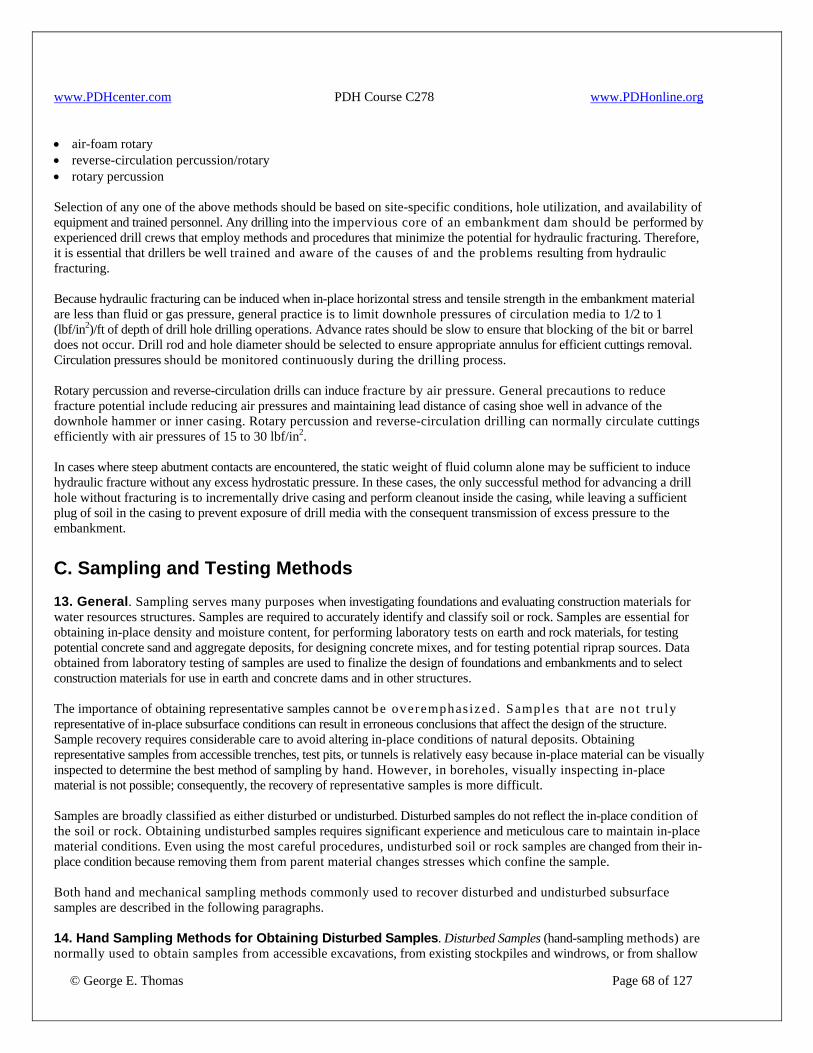
www.PDHcenter.com PDH Course C278 www.PDHonline.org
© George E. Thomas Page 68 of 127
• air-foam rotary • reverse-circulation percussion/rotary • rotary percussion Selection of any one of the above methods should be based on site-specific conditions, hole utilization, and availability of equipment and trained personnel. Any drilling into the impervious core of an embankment dam should be performed by experienced drill crews that employ methods and procedures that minimize the potential for hydraulic fracturing. Therefore, it is essential that drillers be well trained and aware of the causes of and the problems resulting from hydraulic fracturing. Because hydraulic fracturing can be induced when in-place horizontal stress and tensile strength in the embankment material are less than fluid or gas pressure, general practice is to limit downhole pressures of circulation media to 1/2 to 1 (lbf/in2)/ft of depth of drill hole drilling operations. Advance rates should be slow to ensure that blocking of the bit or barrel does not occur. Drill rod and hole diameter should be selected to ensure appropriate annulus for efficient cuttings removal. Circulation pressures should be monitored continuously during the drilling process. Rotary percussion and reverse-circulation drills can induce fracture by air pressure. General precautions to reduce fracture potential include reducing air pressures and maintaining lead distance of casing shoe well in advance of the downhole hammer or inner casing. Rotary percussion and reverse-circulation drilling can normally circulate cuttings efficiently with air pressures of 15 to 30 lbf/in2. In cases where steep abutment contacts are encountered, the static weight of fluid column alone may be sufficient to induce hydraulic fracture without any excess hydrostatic pressure. In these cases, the only successful method for advancing a drill hole without fracturing is to incrementally drive casing and perform cleanout inside the casing, while leaving a sufficient plug of soil in the casing to prevent exposure of drill media with the consequent transmission of excess pressure to the embankment. C. Sampling and Testing Methods 13. General. Sampling serves many purposes when investigating foundations and evaluating construction materials for water resources structures. Samples are required to accurately identify and classify soil or rock. Samples are essential for obtaining in-place density and moisture content, for performing laboratory tests on earth and rock materials, for testing potential concrete sand and aggregate deposits, for designing concrete mixes, and for testing potential riprap sources. Data obtained from laboratory testing of samples are used to finalize the design of foundations and embankments and to select construction materials for use in earth and concrete dams and in other structures. The importance of obtaining representative samples cannot be overemphasized. Samples that are not t ru ly representative of in-place subsurface conditions can result in erroneous conclusions that affect the design of the structure. Sample recovery requires considerable care to avoid altering in-place conditions of natural deposits. Obtaining representative samples from accessible trenches, test pits, or tunnels is relatively easy because in-place material can be visually inspected to determine the best method of sampling by hand. However, in boreholes, visually inspecting in-place material is not possible; consequently, the recovery of representative samples is more difficult. Samples are broadly classified as either disturbed or undisturbed. Disturbed samples do not reflect the in-place condition of the soil or rock. Obtaining undisturbed samples requires significant experience and meticulous care to maintain in-place material conditions. Even using the most careful procedures, undisturbed soil or rock samples are changed from their in-place condition because removing them from parent material changes stresses which confine the sample. Both hand and mechanical sampling methods commonly used to recover disturbed and undisturbed subsurface samples are described in the following paragraphs. 14. Hand Sampling Methods for Obtaining Disturbed Samples. Disturbed Samples (hand-sampling methods) are normally used to obtain samples from accessible excavations, from existing stockpiles and windrows, or from shallow
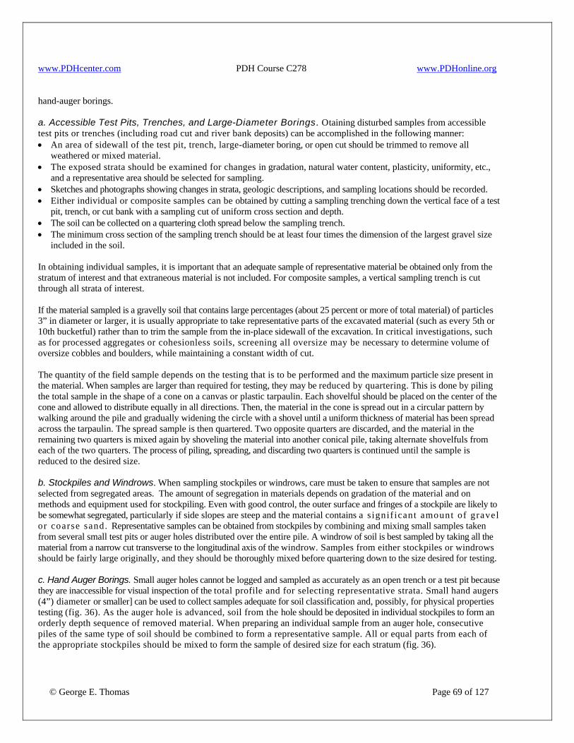
www.PDHcenter.com PDH Course C278 www.PDHonline.org
© George E. Thomas Page 69 of 127
hand-auger borings. a. Accessible Test Pits, Trenches, and Large-Diameter Borings. Otaining disturbed samples from accessible test pits or trenches (including road cut and river bank deposits) can be accomplished in the following manner: • An area of sidewall of the test pit, trench, large-diameter boring, or open cut should be trimmed to remove all
weathered or mixed material. • The exposed strata should be examined for changes in gradation, natural water content, plasticity, uniformity, etc.,
and a representative area should be selected for sampling. • Sketches and photographs showing changes in strata, geologic descriptions, and sampling locations should be recorded. • Either individual or composite samples can be obtained by cutting a sampling trenching down the vertical face of a test
pit, trench, or cut bank with a sampling cut of uniform cross section and depth. • The soil can be collected on a quartering cloth spread below the sampling trench. • The minimum cross section of the sampling trench should be at least four times the dimension of the largest gravel size
included in the soil. In obtaining individual samples, it is important that an adequate sample of representative material be obtained only from the stratum of interest and that extraneous material is not included. For composite samples, a vertical sampling trench is cut through all strata of interest. If the material sampled is a gravelly soil that contains large percentages (about 25 percent or more of total material) of particles 3” in diameter or larger, it is usually appropriate to take representative parts of the excavated material (such as every 5th or 10th bucketful) rather than to trim the sample from the in-place sidewall of the excavation. In critical investigations, such as for processed aggregates or cohesionless soils, screening all oversize may be necessary to determine volume of oversize cobbles and boulders, while maintaining a constant width of cut. The quantity of the field sample depends on the testing that is to be performed and the maximum particle size present in the material. When samples are larger than required for testing, they may be reduced by quartering. This is done by piling the total sample in the shape of a cone on a canvas or plastic tarpaulin. Each shovelful should be placed on the center of the cone and allowed to distribute equally in all directions. Then, the material in the cone is spread out in a circular pattern by walking around the pile and gradually widening the circle with a shovel until a uniform thickness of material has been spread across the tarpaulin. The spread sample is then quartered. Two opposite quarters are discarded, and the material in the remaining two quarters is mixed again by shoveling the material into another conical pile, taking alternate shovelfuls from each of the two quarters. The process of piling, spreading, and discarding two quarters is continued until the sample is reduced to the desired size. b. Stockpiles and Windrows. When sampling stockpiles or windrows, care must be taken to ensure that samples are not selected from segregated areas. The amount of segregation in materials depends on gradation of the material and on methods and equipment used for stockpiling. Even with good control, the outer surface and fringes of a stockpile are likely to be somewhat segregated, particularly if side slopes are steep and the material contains a s ignif icant amount of gravel or coarse sand. Representative samples can be obtained from stockpiles by combining and mixing small samples taken from several small test pits or auger holes distributed over the entire pile. A windrow of soil is best sampled by taking all the material from a narrow cut transverse to the longitudinal axis of the windrow. Samples from either stockpiles or windrows should be fairly large originally, and they should be thoroughly mixed before quartering down to the size desired for testing. c. Hand Auger Borings. Small auger holes cannot be logged and sampled as accurately as an open trench or a test pit because they are inaccessible for visual inspection of the total profile and for selecting representative strata. Small hand augers (4”) diameter or smaller] can be used to collect samples adequate for soil classification and, possibly, for physical properties testing (fig. 36). As the auger hole is advanced, soil from the hole should be deposited in individual stockpiles to form an orderly depth sequence of removed material. When preparing an individual sample from an auger hole, consecutive piles of the same type of soil should be combined to form a representative sample. All or equal parts from each of the appropriate stockpiles should be mixed to form the sample of desired size for each stratum (fig. 36).
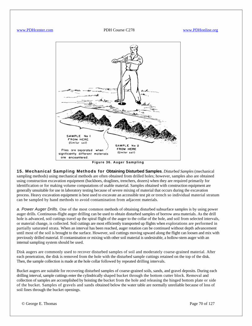
www.PDHcenter.com PDH Course C278 www.PDHonline.org
F igure 36 . Auger Sampl ing
15. Mechanical Sampling Methods for Obtaining Disturbed Samples. Disturbed Samples (mechanical sampling methods) using mechanical methods are often obtained from drilled holes; however, samples also are obtained using construction excavation equipment (backhoes, draglines, trenchers, dozers) when they are required primarily for identification or for making volume computations of usable material. Samples obtained with construction equipment are generally unsuitable for use in laboratory testing because of severe mixing of material that occurs during the excavation process. Heavy excavation equipment is best used to excavate an accessible test pit or trench so individual material stratum can be sampled by hand methods to avoid contamination from adjacent materials. a. Power Auger Drills. One of the most common methods of obtaining disturbed subsurface samples is by using power auger drills. Continuous-flight auger drilling can be used to obtain disturbed samples of borrow area materials. As the drill hole is advanced, soil cuttings travel up the spiral flight of the auger to the collar of the hole, and soil from selected intervals, or material change, is collected. Soil cuttings are most efficiently transported up flights when explorations are performed in partially saturated strata. When an interval has been reached, auger rotation can be continued without depth advancement until most of the soil is brought to the surface. However, soil cuttings moving upward along the flight can loosen and mix with previously drilled material. If contamination or mixing with other soil material is undesirable, a hollow-stem auger with an internal sampling system should be used. Disk augers are commonly used to recover disturbed samples of soil and moderately coarse-grained material. After each penetration, the disk is removed from the hole with the disturbed sample cuttings retained on the top of the disk. Then, the sample collection is made at the hole collar followed by repeated drilling intervals. Bucket augers are suitable for recovering disturbed samples of coarse-grained soils, sands, and gravel deposits. During each drilling interval, sample cuttings enter the cylindrically shaped bucket through the bottom cutter block. Removal and collection of samples are accomplished by hoisting the bucket from the hole and releasing the hinged bottom plate or side of the bucket. Samples of gravels and sands obtained below the water table are normally unreliable because of loss of soil fines through the bucket openings.
© George E. Thomas Page 70 of 127

www.PDHcenter.com PDH Course C278 www.PDHonline.org
© George E. Thomas Page 71 of 127
b. Reverse-Circulation Drills. Reverse-circulation drills work well for recovering sand, gravel, and cobble-size disturbed samples. However, this sampling method is relatively expensive and is not used for borrow area investigations. These drills use a double-walled drill stem and compressed air to circulate drill cuttings for collection at the hole collar. Compressed air is pumped down the annulus between the inner and outer walls of the double-walled drill rod, and cuttings are forced upward through the center rod as drilling progresses. Drill cuttings are collected at the discharge spout of a special funnel-shaped cyclone assembly designed to dissipate the energy of the compressed air and deposit cuttings in the order drilled. This method of disturbed sampling is considered most reliable to produce a noncontaminated sample because the drill stem seals previously drilled material zones. Normally, coarse gravels and cobbles are broken by impact of the double wall casing shoe, but this is easily identified by fresh fracture surfaces. Gradation tests are unreliable if coarse particle fracturing occurs. c. Protecting and Preparing Disturbed Samples for Shipping. Disturbed samples of 75 lbm or more should be placed in bags or other suitable containers that prevent loss of moisture or fine fraction from the soil. Asphalt coated burlap sacks with an inner plastic liner are commonly used for protecting and shipping disturbed soil samples. Samples of silty or clayey borrow soils can be allowed some moisture loss as long as studies show no irreversible processes occur from air drying. These soils will be dried in the laboratory for development of compaction curves. The coated burlap sack with plastic liner has proved satisfactory for most borrow studies of silty and clayey soils. When proposed for use as borrow material, samples of silt and clay for laboratory testing should be protected against drying by placement in waterproof bags or other suitable containers. Sand and gravel samples should be shipped in closely woven bags and should be air dried before they are placed in the bags. When sack samples are shipped by public carrier, they should be double sacked. 16. Hand Sampling Methods for Obtaining Undisturbed Samples. a. Undisturbed Hand-Sampling Methods. Undisturbed samples in the form of cubes, cylinders, or irregularly shaped masses can be obtained from strata exposed in the sides or bottoms of open excavations, test pits, trenches, and large-diameter auger holes. Such samples are useful for determining in-place density and moisture content and for other laboratory tests. Hand cut cylinder samples and block samples provide the highest quality undisturbed samples for laboratory testing and are often preferred in critical studies of weak zones when access is available. Generally, sampling is only possible in unsaturated zones because dewatering can cause increases in effective stress and possible consolidation of sensitive material. Sampling by hand-carved cylinder sample is depicted on figure 37. An elevated bench is constructed in a test pit or accessible shaft. A cylinder, sharpened on one end, is placed on a level surface and is pressed into the soil as the sample is trimmed with a knife to a diameter slightly larger than the cutting edge. The incremental process of trimming and pressing is continued until the cylinder is overfilled with soil. The sample bottom can be severed from parent material by spade or shovel and ends trimmed flush the end of the cylinder. This method is effective for soils generally wet of laboratory optimum water content and which contain maximum particle sizes less than coarse sand. If soils are very fine-grained and wet, cylinders can possibly be pushed the complete depth without trimming in advance of the cutting edge. Several devices such as the U.S. Army Corps of Engineers drive cylinder or the "Elly Volumeter" have been developed. Samples can be extruded from cylinders into laboratory test chambers. The government has obtained large-diameter cylinders (8” to 12”) for testing by pushing into compacted fills. Cylinders were pushed with drawbars of bulldozers or buckets of front end loaders. This sampling method may be particularly effective for compacted clay liners placed wet of optimum water content.
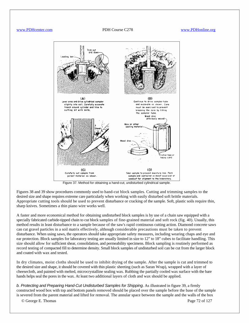
www.PDHcenter.com PDH Course C278 www.PDHonline.org
Figure 37. Method for obtaining a hand-cut, undisturbed cylindrical sample.
Figures 38 and 39 show procedures commonly used to hand-cut block samples. Cutting and trimming samples to the desired size and shape requires extreme care particularly when working with easily disturbed soft brittle materials. Appropriate cutting tools should be used to prevent disturbance or cracking of the sample. Soft, plastic soils require thin, sharp knives. Sometimes a thin piano wire works well. A faster and more economical method for obtaining undisturbed block samples is by use of a chain saw equipped with a specially fabricated carbide-tipped chain to cut block samples of fine-grained material and soft rock (fig. 40). Usually, this method results in least disturbance to a sample because of the saw's rapid continuous cutting action. Diamond concrete saws can cut gravel particles in a soil matrix effectively, although considerable precautions must be taken to prevent disturbance. When using saws, the operators should take appropriate safety measures, including wearing chaps and eye and ear protection. Block samples for laboratory testing are usually limited in size to 12” to 18” cubes to facilitate handling. This size should allow for sufficient shear, consolidation, and permeability specimens. Block sampling is routinely performed as record testing of compacted fill to determine density. Small block samples of undisturbed soil can be cut from the larger block and coated with wax and tested. In dry climates, moist cloths should be used to inhibit drying of the sample. After the sample is cut and trimmed to the desired size and shape, it should be covered with thin plastic sheeting (such as Saran Wrap), wrapped with a layer of cheesecloth, and painted with melted, microcrystalline sealing wax. Rubbing the partially cooled wax surface with the bare hands helps seal the pores in the wax. At least two additional layers of cloth and wax should be applied.
© George E. Thomas Page 72 of 127
b. Protecting and Preparing Hand-Cut Undisturbed Samples for Shipping. As illustrated in figure 39, a firmly constructed wood box with top and bottom panels removed should be placed over the sample before the base of the sample is severed from the parent material and lifted for removal. The annular space between the sample and the walls of the box
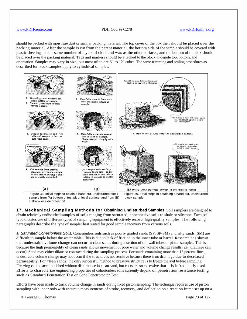
www.PDHcenter.com PDH Course C278 www.PDHonline.org
should be packed with moist sawdust or similar packing material. The top cover of the box then should be placed over the packing material. After the sample is cut from the parent material, the bottom side of the sample should be covered with plastic sheeting and the same number of layers of cloth and wax as the other surfaces; and the bottom of the box should be placed over the packing material. Tags and markers should be attached to the block to denote top, bottom, and orientation. Samples may vary in size, but most often are 6” to 12” cubes. The same trimming and sealing procedures as described for block samples apply to cylindrical samples.
Figure 38. Initial steps to obtain a hand-cut, undisturbed block Figure 39. Final steps in obtaining a hand-cut, undisturbed sample from (A) bottom of test pit or level surface, and from (B) block sample cutbank or side of test pit. 17. Mechanical Sampling Methods for Obtaining Undisturbed Samples. Soil samplers are designed to obtain relatively undisturbed samples of soils ranging from saturated, noncohesive soils to shale or siltstone. Each soil type dictates use of different types of sampling equipment to effectively recover high-quality samples. The following paragraphs describe the type of sampler best suited for good sample recovery from various soils. a. Saturated Cohesionless Soils. Cohesionless soils such as poorly graded sands (SP, SP-SM) and silty sands (SM) are difficult to sample below the water table. This is due to lack of friction in the inner tube or barrel. Research has shown that undesirable volume change can occur in clean sands during insertion of thinwall tubes or piston samples. This is because the high permeability of clean sands allows movement of pore water and volume change results (i.e., drainage can occur). Sand may either dilate or contract during the sampling process. For sands containing more than 15 percent fines, undesirable volume change may not occur if the structure is not sensitive because there is no drainage due to decreased permeability. For clean sands, the only successful method to preserve structure is to freeze the soil before sampling. Freezing can be accomplished without disturbance in clean sand, but costs are so excessive that it is infrequently used. Efforts to characterize engineering properties of cohesionless soils currently depend on penetration resistance testing such as Standard Penetration Test or Cone Penetrometer Test.
© George E. Thomas Page 73 of 127
Efforts have been made to track volume change in sands during fixed piston sampling. The technique requires use of piston sampling with inner rods with accurate measurements of stroke, recovery, and deflection on a reaction frame set up on a
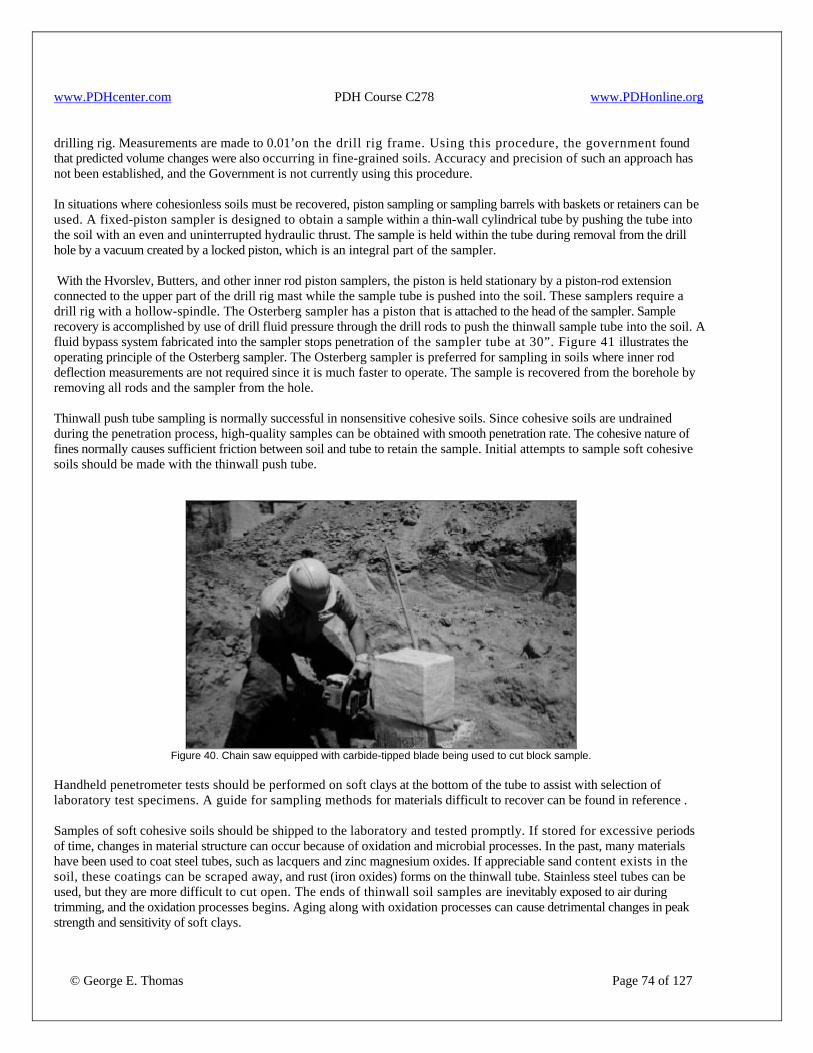
www.PDHcenter.com PDH Course C278 www.PDHonline.org
drilling rig. Measurements are made to 0.01’on the drill rig frame. Using this procedure, the government found that predicted volume changes were also occurring in fine-grained soils. Accuracy and precision of such an approach has not been established, and the Government is not currently using this procedure. In situations where cohesionless soils must be recovered, piston sampling or sampling barrels with baskets or retainers can be used. A fixed-piston sampler is designed to obtain a sample within a thin-wall cylindrical tube by pushing the tube into the soil with an even and uninterrupted hydraulic thrust. The sample is held within the tube during removal from the drill hole by a vacuum created by a locked piston, which is an integral part of the sampler. With the Hvorslev, Butters, and other inner rod piston samplers, the piston is held stationary by a piston-rod extension connected to the upper part of the drill rig mast while the sample tube is pushed into the soil. These samplers require a drill rig with a hollow-spindle. The Osterberg sampler has a piston that is attached to the head of the sampler. Sample recovery is accomplished by use of drill fluid pressure through the drill rods to push the thinwall sample tube into the soil. A fluid bypass system fabricated into the sampler stops penetration of the sampler tube at 30”. Figure 41 illustrates the operating principle of the Osterberg sampler. The Osterberg sampler is preferred for sampling in soils where inner rod deflection measurements are not required since it is much faster to operate. The sample is recovered from the borehole by removing all rods and the sampler from the hole. Thinwall push tube sampling is normally successful in nonsensitive cohesive soils. Since cohesive soils are undrained during the penetration process, high-quality samples can be obtained with smooth penetration rate. The cohesive nature of fines normally causes sufficient friction between soil and tube to retain the sample. Initial attempts to sample soft cohesive soils should be made with the thinwall push tube.
Figure 40. Chain saw equipped with carbide-tipped blade being used to cut block sample.
Handheld penetrometer tests should be performed on soft clays at the bottom of the tube to assist with selection of laboratory test specimens. A guide for sampling methods for materials difficult to recover can be found in reference . Samples of soft cohesive soils should be shipped to the laboratory and tested promptly. If stored for excessive periods of time, changes in material structure can occur because of oxidation and microbial processes. In the past, many materials have been used to coat steel tubes, such as lacquers and zinc magnesium oxides. If appreciable sand content exists in the soil, these coatings can be scraped away, and rust (iron oxides) forms on the thinwall tube. Stainless steel tubes can be used, but they are more difficult to cut open. The ends of thinwall soil samples are inevitably exposed to air during trimming, and the oxidation processes begins. Aging along with oxidation processes can cause detrimental changes in peak strength and sensitivity of soft clays.
© George E. Thomas Page 74 of 127
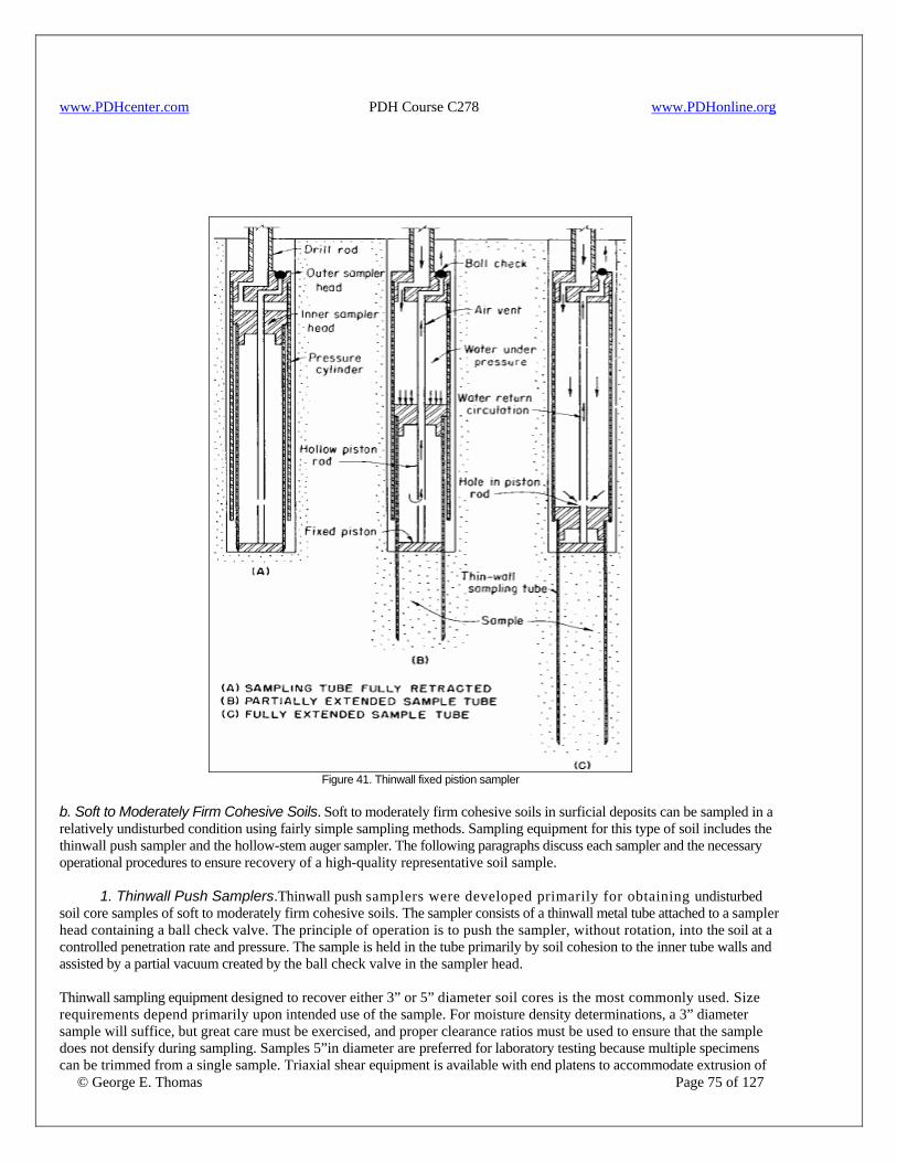
www.PDHcenter.com PDH Course C278 www.PDHonline.org
Figure 41. Thinwall fixed pistion sampler
b. Soft to Moderately Firm Cohesive Soils. Soft to moderately firm cohesive soils in surficial deposits can be sampled in a relatively undisturbed condition using fairly simple sampling methods. Sampling equipment for this type of soil includes the thinwall push sampler and the hollow-stem auger sampler. The following paragraphs discuss each sampler and the necessary operational procedures to ensure recovery of a high-quality representative soil sample. 1. Thinwall Push Samplers.Thinwall push samplers were developed primarily for obtaining undisturbed soil core samples of soft to moderately firm cohesive soils. The sampler consists of a thinwall metal tube attached to a sampler head containing a ball check valve. The principle of operation is to push the sampler, without rotation, into the soil at a controlled penetration rate and pressure. The sample is held in the tube primarily by soil cohesion to the inner tube walls and assisted by a partial vacuum created by the ball check valve in the sampler head.
© George E. Thomas Page 75 of 127
Thinwall sampling equipment designed to recover either 3” or 5” diameter soil cores is the most commonly used. Size requirements depend primarily upon intended use of the sample. For moisture density determinations, a 3” diameter sample will suffice, but great care must be exercised, and proper clearance ratios must be used to ensure that the sample does not densify during sampling. Samples 5”in diameter are preferred for laboratory testing because multiple specimens can be trimmed from a single sample. Triaxial shear equipment is available with end platens to accommodate extrusion of
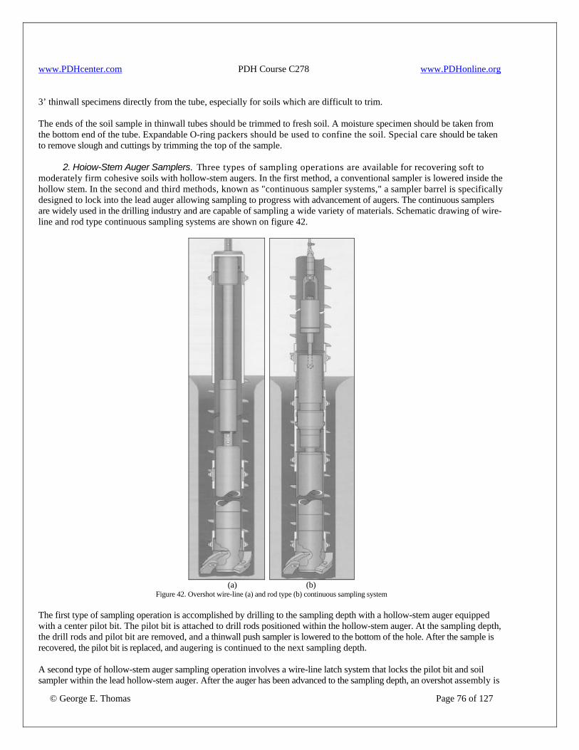
www.PDHcenter.com PDH Course C278 www.PDHonline.org
3’ thinwall specimens directly from the tube, especially for soils which are difficult to trim. The ends of the soil sample in thinwall tubes should be trimmed to fresh soil. A moisture specimen should be taken from the bottom end of the tube. Expandable O-ring packers should be used to confine the soil. Special care should be taken to remove slough and cuttings by trimming the top of the sample. 2. Hoiow-Stem Auger Samplers. Three types of sampling operations are available for recovering soft to moderately firm cohesive soils with hollow-stem augers. In the first method, a conventional sampler is lowered inside the hollow stem. In the second and third methods, known as "continuous sampler systems," a sampler barrel is specifically designed to lock into the lead auger allowing sampling to progress with advancement of augers. The continuous samplers are widely used in the drilling industry and are capable of sampling a wide variety of materials. Schematic drawing of wire-line and rod type continuous sampling systems are shown on figure 42.
(a) (b)
Figure 42. Overshot wire-line (a) and rod type (b) continuous sampling system The first type of sampling operation is accomplished by drilling to the sampling depth with a hollow-stem auger equipped with a center pilot bit. The pilot bit is attached to drill rods positioned within the hollow-stem auger. At the sampling depth, the drill rods and pilot bit are removed, and a thinwall push sampler is lowered to the bottom of the hole. After the sample is recovered, the pilot bit is replaced, and augering is continued to the next sampling depth.
© George E. Thomas Page 76 of 127
A second type of hollow-stem auger sampling operation involves a wire-line latch system that locks the pilot bit and soil sampler within the lead hollow-stem auger. After the auger has been advanced to the sampling depth, an overshot assembly is

www.PDHcenter.com PDH Course C278 www.PDHonline.org
© George E. Thomas Page 77 of 127
lowered by wire-line to unlock and latch onto the pilot bit for removal from the hole. Then, a thinwall sampler with a head bearing assembly is lowered by wire-line and locked within the lead auger section. Sampling is accomplished by continuing auger rotation and penetration, which allows the center core material to enter the thinwall sampler. The head bearing assembly on the sampler allows the sample tube to remain stationary while the auger is rotating. At the end of the sample run, the overshot is lowered by wire-line to release the sampler lock mechanism, latch onto the sampler, and remove it with the soil sample from the hole. The wire-line hollow-stem auger sampling system can be used to successfully sample a wide variety of soils. Some difficulties may be experienced with latching systems in soils below the water table which heave into the hollow stem. Wire-line line systems are economical due to rapid continuous sampling capability. They are used extensively for hazardous waste site characterization studies. Drill rod systems discussed below are preferred for large-diameter soil samples where detailed studies of engineering properties are required. Inner barrels can be equipped with split liners or Plexiglas liners. Sample diameters of up to 4”are currently available in wire-line systems. Typical sample lengths are 5’but may be shortened if sample disturbance is evident. The third and most recently developed hollow-stem auger sampling system involves using rods to lower, hold, and hoist a continuous sampler unit designed to recover samples during auger penetration. This system positively eliminates rotation of the sampler as the auger rotates. It is considered the best mechanical sampling system available for recovery of undisturbed soil samples by hollow-stem auger. The stability of any sampling tool is critical to recovery of representative undisturbed samples. With hollow-stem augers, the inner barrel or sample tube that receives the soil core must not rotate as soil enters the sampler. A sampler with a head bearing assembly can rotate if cuttings are allowed to accumulate in the annulus between the outer rotating auger and the inner sample barrel. To eliminate any chance of movement of the inner barrel, the continuous sampler system is rigidly connected to rods that extend up through the hollow-stem auger to a yoke located above the rotating auger drillhead. Then, the outer auger is allowed to rotate for drilling penetration, but the sampler within the auger is held to prevent rotation as soil core enters the sample tube. As with the wire-line systems, typical sampling intervals are 1.5 m; but for large-diameter samples for laboratory testing, this interval should be shortened to reduce friction buildup in liners and/or the tendency to use larger clearance ratios and overcut the sample. Samplers up to 6” in diameter are available with the drill rod hollow-stem auger system. The large diameter capability and positive anti-rotation of the inner rod system make this the preferred method when detailed engineering properties studies are required. To recover a sample with the continuous sampler system, all sampler connecting rods and the sampler are removed from the auger to retrieve the soil core. This is followed by lowering the sampling unit to the hole bottom for continuation of sampling operations. Both continuous hollow-stem auger sampling systems have adjustments for lead distance of the soil cutting shoe and different clearance ratios for the shoe. As with the Denison soil core barrel, the lead distance and clearance ratios must be optimized for best sample recovery. In general, softer soils require more lead distance of the cutting shoe below auger flights. More cohesive soils require larger clearance ratios to avoid buildup of friction inside liners. Both the wire-line and inner rod operated hollow-stem auger systems will accept clear acrylic liners. Plastic liners should have walls thick enough to confine the core without deflecting (usually about ¼”). Numerous measurements are taken with micrometers to ensure that liner diameters required for accepting samples are maintained. The plastic liners can be cut flush with soil ends, and plastic caps or expandable O-ring packers can be used to seal specimen ends to preserve in-place moisture content. Use of plastic liners permits sample inspection and adjustments for clearance ratio and shoe lead distance. Manufacturer supplied shoes are designed for successful recovery of a wide variety of soils but may not provide optimum sampling for advanced engineering properties testing. For critical samples, shoes of varying lead distance and clearance ratios can be readily machined by local commercial machine shops. The most frequent problem is the tendency to use too large a clearance ratio during sampling. This can result in a large air gap inside the sample liner and possible alteration of soil properties. The goal is to provide a sample which fills the sample liner without objectionable friction that result in compression and densification of the soil. If an air gap exists, the clearance ratio should be reduced. If excessive friction develops in the liners, either decrease sample length or increase clearance ratio.
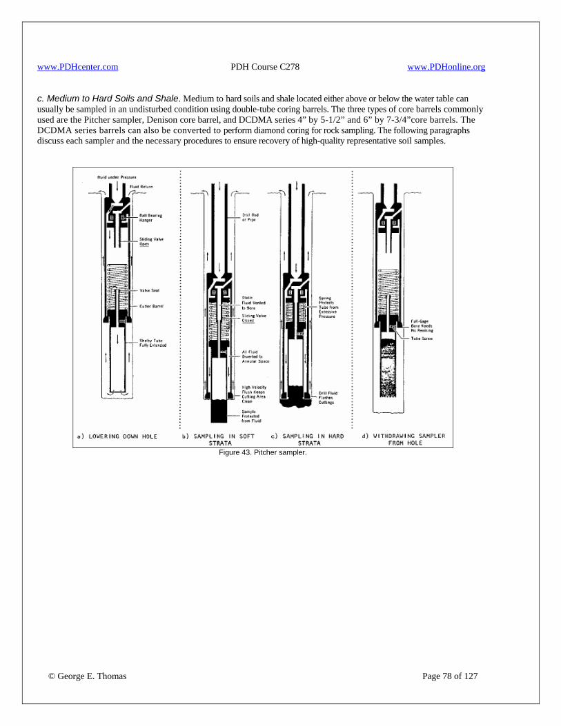
www.PDHcenter.com PDH Course C278 www.PDHonline.org
c. Medium to Hard Soils and Shale. Medium to hard soils and shale located either above or below the water table can usually be sampled in an undisturbed condition using double-tube coring barrels. The three types of core barrels commonly used are the Pitcher sampler, Denison core barrel, and DCDMA series 4” by 5-1/2” and 6” by 7-3/4”core barrels. The DCDMA series barrels can also be converted to perform diamond coring for rock sampling. The following paragraphs discuss each sampler and the necessary procedures to ensure recovery of high-quality representative soil samples.
Figure 43. Pitcher sampler.
© George E. Thomas Page 78 of 127
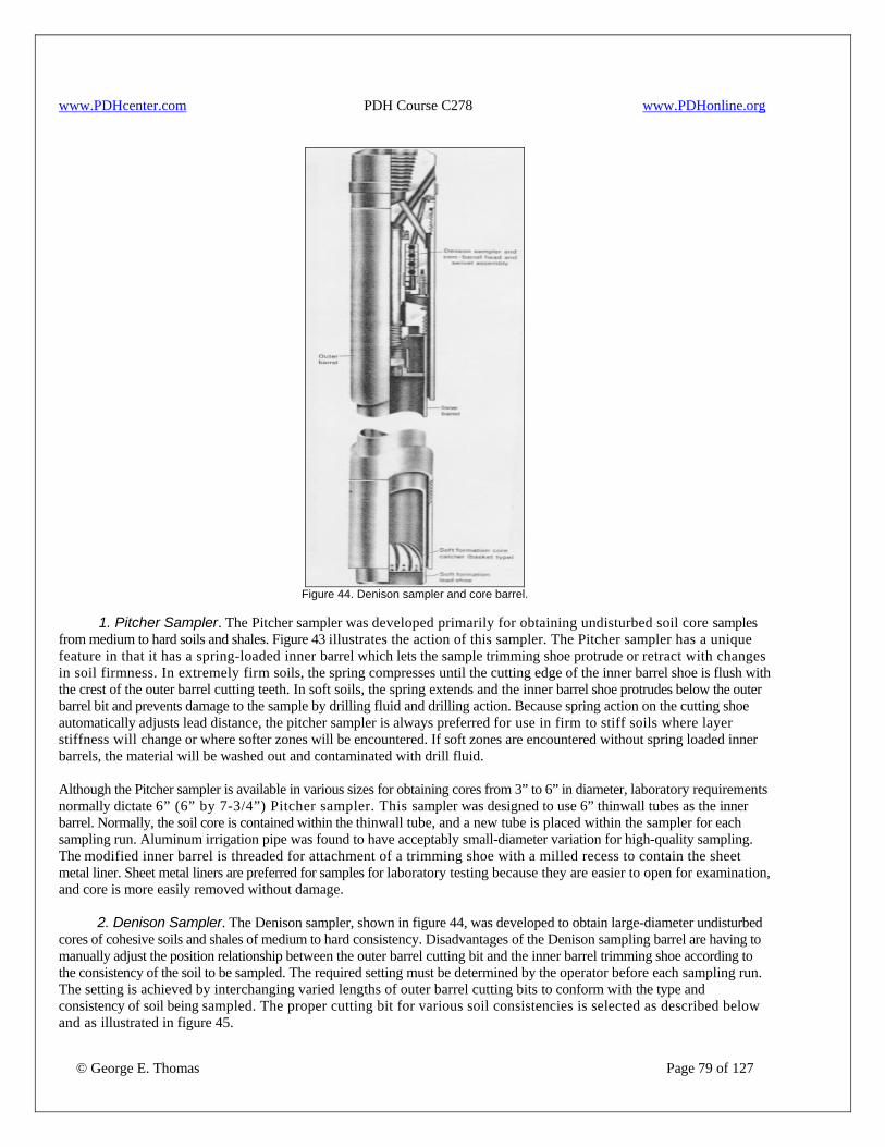
www.PDHcenter.com PDH Course C278 www.PDHonline.org
Figure 44. Denison sampler and core barrel.
1. Pitcher Sampler. The Pitcher sampler was developed primarily for obtaining undisturbed soil core samples from medium to hard soils and shales. Figure 43 illustrates the action of this sampler. The Pitcher sampler has a unique feature in that it has a spring-loaded inner barrel which lets the sample trimming shoe protrude or retract with changes in soil firmness. In extremely firm soils, the spring compresses until the cutting edge of the inner barrel shoe is flush with the crest of the outer barrel cutting teeth. In soft soils, the spring extends and the inner barrel shoe protrudes below the outer barrel bit and prevents damage to the sample by drilling fluid and drilling action. Because spring action on the cutting shoe automatically adjusts lead distance, the pitcher sampler is always preferred for use in firm to stiff soils where layer stiffness will change or where softer zones will be encountered. If soft zones are encountered without spring loaded inner barrels, the material will be washed out and contaminated with drill fluid. Although the Pitcher sampler is available in various sizes for obtaining cores from 3” to 6” in diameter, laboratory requirements normally dictate 6” (6” by 7-3/4”) Pitcher sampler. This sampler was designed to use 6” thinwall tubes as the inner barrel. Normally, the soil core is contained within the thinwall tube, and a new tube is placed within the sampler for each sampling run. Aluminum irrigation pipe was found to have acceptably small-diameter variation for high-quality sampling. The modified inner barrel is threaded for attachment of a trimming shoe with a milled recess to contain the sheet metal liner. Sheet metal liners are preferred for samples for laboratory testing because they are easier to open for examination, and core is more easily removed without damage. 2. Denison Sampler. The Denison sampler, shown in figure 44, was developed to obtain large-diameter undisturbed cores of cohesive soils and shales of medium to hard consistency. Disadvantages of the Denison sampling barrel are having to manually adjust the position relationship between the outer barrel cutting bit and the inner barrel trimming shoe according to the consistency of the soil to be sampled. The required setting must be determined by the operator before each sampling run. The setting is achieved by interchanging varied lengths of outer barrel cutting bits to conform with the type and consistency of soil being sampled. The proper cutting bit for various soil consistencies is selected as described below and as illustrated in figure 45.
© George E. Thomas Page 79 of 127
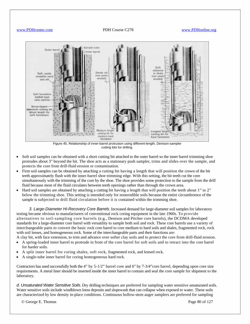
www.PDHcenter.com PDH Course C278 www.PDHonline.org
Figure 45. Relationship of inner-barrel protrusion using different-length, Denison-sampler
cutting bits for drilling.
• Soft soil samples can be obtained with a short cutting bit attached to the outer barrel so the inner barrel trimming shoe protrudes about 3” beyond the bit. The shoe acts as a stationary push sampler, trims and slides over the sample, and protects the core from drill-fluid erosion or contamination.
• Firm soil samples can be obtained by attaching a cutting bit having a length that will position the crown of the bit teeth approximately flush with the inner-barrel shoe trimming edge. With this setting, the bit teeth cut the core simultaneously with the trimming of the core by the shoe. The shoe provides some protection to the sample from the drill fluid because most of the fluid circulates between teeth openings rather than through the crown area.
• Hard soil samples are obtained by attaching a cutting bit having a length that will position the teeth about 1” to 2” below the trimming shoe. This setting is intended only for nonerodible soils because the entire circumference of the sample is subjected to drill fluid circulation before it is contained within the trimming shoe.
3. Large-Diameter Hi-Recovery Core Barrels. Increased demand for large-diameter soil samples for laboratory testing became obvious to manufacturers of conventional rock coring equipment in the late 1960s. To provide alternatives to soil-sampling core barrels (e.g., Denison and Pitcher core barrels), the DCDMA developed standards for a large-diameter core barrel with versatility to sample both soil and rock. These core barrels use a variety of interchangeable parts to convert the basic rock core barrel to core medium to hard soils and shales, fragmented rock, rock with soil lenses, and homogeneous rock. Some of the interchangeable parts and their functions are: A clay bit, with face extension, to trim and advance over softer clay soils and to protect the core from drill-fluid erosion. • A spring-loaded inner barrel to protrude in front of the core barrel for soft soils and to retract into the core barrel
for harder soils. • A split inner barrel for coring shales, soft rock, fragmented rock, and lensed rock. • A single-tube inner barrel for coring homogeneous hard rock. Contractors has used successfully both the 4” by 5-1/2” barrel core and 6” by 7-3/4”core barrel, depending upon core size requirements. A metal liner should be inserted inside the inner barrel to contain and seal the core sample for shipment to the laboratory.
© George E. Thomas Page 80 of 127
d. Unsaturated Water Sensitive Soils. Dry drilling techniques are preferred for sampling water sensitive unsaturated soils. Water sensitive soils include windblown loess deposits and slopewash that can collapse when exposed to water. These soils are characterized by low density in-place conditions. Continuous hollow-stem auger samplers are preferred for sampling
www.PDHcenter.com PDH Course C278 www.PDHonline.org
© George E. Thomas Page 81 of 127
these deposits because exposure to drilling fluids is not permitted. If surface exposures are accessible, block samples provide the highest quality sample. Sampling studies in loess have shown that thinwall tubes and Pitcher sampling result in unacceptable sampling disturbance. Thinwall samplers compacted loess, when dry methods were used to advance the borehole. Pitcher sampling allowed for some exposure to fluid if not properly operated. 18. Casing Advancer. Manufacturers have adapted wire-line drilling principles to accommodate a wide variety of sampling methods. The wire-line casing advancer can be used to advance standard BW, HW, and HW, casing through difficult deposits such as coarse alluvium or highly fractured materials while still protecting the drillhole. Casing advancers have a center pilot bit which is normally configured as a tricone rockbit. In one case, where it was necessary to drill through several steel settlement plates, a pilot bit made with diamonds was used. Casing bits are normally diamonds, but carbide insert drag bits have been used in soils. After the casing is advanced to depth for testing or sampling, the center pilot bit can be removed by wireline, and a flush casing is left. The casing advancer has proved effective for the following operations: • Conventional or wire-line coring through casing • Casing through landslide or alluvial materials • Conventional or wire-line thinwall tube sampling through casing • Penetration resistance testing and sampling ahead of casing • Tie back anchor installation through casing • Installation of well screen, perforated drain, or piezometers through casing The casing advancer has been used to successfully perform penetration resistance tests in loose sands below the water table. Drilling was performed with carbide casing bit and no pilot bit. The primary reason for success was that a fluid column was maintained in the casing that prevented heaving sands from entering, and careful attention was paid to circulation to avoid hydraulic fracturing. 19. Rock Sampling Methods. Core barrels are available to obtain cores from ¾’ to 6” in diameter. There are two principal types of core barrels: (1) single tube and (2) double tube. The DCDMA has standardized dimensions for four series of conventional rock core barrels. The series are denoted as WG, WT, WM, and Large Diameter. The W series barrels can be obtained for nominal hole sizes R through H. The differences between these designs are primarily related to methods of fluid circulation and optimizing core diameters. For example, the G series of tubes is the most basic in design and allow for more core exposure to drill fluid. The T series barrels have thinner tube walls, which result in larger core. The G and T series are available in single tube or double-tube configurations. In the M series barrel, the inner tube is threaded to receive the lifter with resulting less exposure of core to drill fluid. The large-diameter core barrels have better control of drill fluid circulation and core protection. The M and Large Diameter series barrels have double-tube design. As one progresses through G, T, M, and Large Diameter, the ability to retrieve difficult cores increases. Double-tube core barrels can be either rigid or swivel design. The Government uses either M or Large Diameter double-tube core barrels for the majority of rock coring operations with conventional barrels. Figure 46 shows a schematic view of typical M and Large Diameter double-tube swivel core barrels with a split liner recommended for most investigations. When DCDMA, standard drawings are compared to drill manufacturers literature, it is difficult to distinguish which DCDMA core barrel series is available. Most manufacturers offer conventional barrels equivalent to the M series. Normally, R, E, A, and B hole size cores normally apply only to instrumentation or stabilization applications such as overcoring studies or rock bolt installations. For investigation purposes, the government specifies a minimum hole size of N for conventional core barrels. The single-tube core barrel is a basic design and consists of a core barrel head, a core barrel, and an attached coring bit that cuts an annular groove to permit passage of drilling fluid pumped through the drill rod. This design exposes the core to drilling fluid over its entire length and can result in serious core erosion of unconsolidated or weakly cemented materials. The single-tube core barrel is no longer used except in unique situations, such as in concrete sampling or when using "packsack-type" drills. Single-tube core barrels or masonry core barrels are frequently used for coring soil cement dam facings for construction control. Single-tube core barrels are not recommended for coring operations in concrete dams. The rigid-type, double-tube core barrel provides an inner barrel which rotates with the outer barrel but protects the core from drilling fluid. The rigid-type, double-tube core barrel has been used successfully in soft to medium-hard formations and in hard, broken formations. A problem arises in core abrasion caused by the rotating inner tube, and soft, easily disturbed
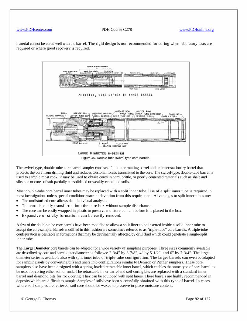
www.PDHcenter.com PDH Course C278 www.PDHonline.org
material cannot be cored well with the barrel. The rigid design is not recommended for coring when laboratory tests are required or where good recovery is required.
Figure 46. Double-tube swivel-type core barrels.
The swivel-type, double-tube core barrel sampler consists of an outer rotating barrel and an inner stationary barrel that protects the core from drilling fluid and reduces torsional forces transmitted to the core. The swivel-type, double-tube barrel is used to sample most rock; it may be used to obtain cores in hard, brittle, or poorly cemented materials such as shale and siltstone or cores of soft partially consolidated or weakly cemented soils. Most double-tube core barrel inner tubes may be replaced with a split inner tube. Use of a split inner tube is required in most investigations unless special conditions warrant deviation from this requirement. Advantages to split inner tubes are: • The undisturbed core allows detailed visual analysis. • The core is easily transferred into the core box without sample disturbance. • The core can be easily wrapped in plastic to preserve moisture content before it is placed in the box. • Expansive or sticky formations can be easily removed. A few of the double-tube core barrels have been modified to allow a split liner to be inserted inside a solid inner tube to accept the core sample. Barrels modified in this fashion are sometimes referred to as "triple-tube" core barrels. A triple-tube configuration is desirable in formations that may be detrimentally affected by drill fluid which could penetrate a single-split inner tube. The Large Diameter core barrels can be adapted for a wide variety of sampling purposes. Three sizes commonly available are described by core and barrel outer diameter as follows: 2-3/4” by 3-7/8”, 4” by 5-1/2”, and 6” by 7-3/4”. The large-diameter series is available also with split inner tube or triple-tube configuration. The larger barrels can even be adapted for sampling soils by converting bits and liners into configurations similar to Denison or Pitcher samplers. These core samplers also have been designed with a spring-loaded retractable inner barrel, which enables the same type of core barrel to be used for coring either soil or rock. The retractable inner barrel and soil-coring bits are replaced with a standard inner barrel and diamond bits for rock coring. They can be equipped with split liners. These barrels are highly recommended in deposits which are difficult to sample. Samples of soils have been successfully obtained with this type of barrel. In cases where soil samples are retrieved, soil core should be waxed to preserve in-place moisture content.
© George E. Thomas Page 82 of 127
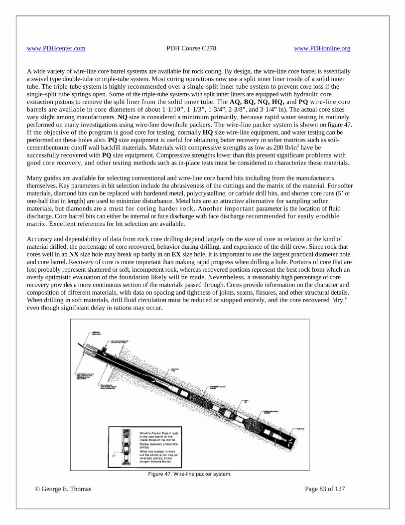
www.PDHcenter.com PDH Course C278 www.PDHonline.org
A wide variety of wire-line core barrel systems are available for rock coring. By design, the wire-line core barrel is essentially a swivel type double-tube or triple-tube system. Most coring operations now use a split inner liner inside of a solid inner tube. The triple-tube system is highly recommended over a single-split inner tube system to prevent core loss if the single-split tube springs open. Some of the triple-tube systems with split inner liners are equipped with hydraulic core extraction pistons to remove the split liner from the solid inner tube. The AQ, BQ, NQ, HQ, and PQ wire-line core barrels are available in core diameters of about 1-1/10”, 1-1/3”, 1-3/4”, 2-3/8”, and 3-1/4” in). The actual core sizes vary slight among manufacturers. NQ size is considered a minimum primarily, because rapid water testing is routinely performed on many investigations using wire-line downhole packers. The wire-line packer system is shown on figure 47. If the objective of the program is good core for testing, normally HQ size wire-line equipment, and water testing can be performed on these holes also. PQ size equipment is useful for obtaining better recovery in softer matrices such as soil-cementbentonite cutoff wall backfill materials. Materials with compressive strengths as low as 200 lb/in2 have be successfully recovered with PQ size equipment. Compressive strengths lower than this present significant problems with good core recovery, and other testing methods such as in-place tests must be considered to characterize these materials. Many guides are available for selecting conventional and wire-line core barrel bits including from the manufacturers themselves. Key parameters in bit selection include the abrasiveness of the cuttings and the matrix of the material. For softer materials, diamond bits can be replaced with hardened metal, polycrystalline, or carbide drill bits, and shorter core runs (5’ or one-half that in length) are used to minimize disturbance. Metal bits are an attractive alternative for sampling softer materials, but diamonds are a must for coring harder rock. Another important parameter is the location of fluid discharge. Core barrel bits can either be internal or face discharge with face discharge recommended for easily erodible matrix. Excellent references for bit selection are available. Accuracy and dependability of data from rock core drilling depend largely on the size of core in relation to the kind of material drilled, the percentage of core recovered, behavior during drilling, and experience of the drill crew. Since rock that cores well in an NX size hole may break up badly in an EX size hole, it is important to use the largest practical diameter hole and core barrel. Recovery of core is more important than making rapid progress when drilling a hole. Portions of core that are lost probably represent shattered or soft, incompetent rock, whereas recovered portions represent the best rock from which an overly optimistic evaluation of the foundation likely will be made. Nevertheless, a reasonably high percentage of core recovery provides a more continuous section of the materials passed through. Cores provide information on the character and composition of different materials, with data on spacing and tightness of joints, seams, fissures, and other structural details. When drilling in soft materials, drill fluid circulation must be reduced or stopped entirely, and the core recovered "dry," even though significant delay in rations may occur.
Figure 47. Wire-line packer system.
© George E. Thomas Page 83 of 127

www.PDHcenter.com PDH Course C278 www.PDHonline.org
© George E. Thomas Page 84 of 127
Many of the principles of conventional coring can apply to wire-line coring. The core barrel is fitted with a coring bit and is lowered into the hole with the hollow drill rod. Circulation of drilling fluid should begin before the core barrel reaches the bottom of the hole to lift cuttings or sludge and prevent them from entering the core barrel at the start of coring. The optimal rotational speed of drilling varies with type of bit used, diameter of core barrel, and kind of material to be cored. Excessive rotational speed results in chattering and rapid bit wear and will break the core. Low rotational speed results in less wear and tear on the bit and better cores, but lower rates of progress. It is critical to minimize vibration from uneven rods or poor drive head assembly. Vibration of the drill stem will cause vibrating and chattering, resulting in bit blockage, broken core, and poor core recovery. If rotation rates must be decreased because of vibration, the mass or pressure on the bit must also be decreased or polishing and dulling of the diamonds will occur. Rotational speed must also be adjusted for core barrel diameter. Drillers must evaluate all factors when considering coring rates and pressures. Bit wear can provide many clues when selecting proper rotational rates once the appropriate bit is specified for the material. If wire-line coring is performed, bit inspection will cause trip time delay. The rate at which the coring bit advances depends on firmness of material, amount of pressure applied on the bit, and rotational speed. Pressure must be carefully adjusted by the driller; excessive pressure causes the bit to plug and may shear the core from its base. Bit pressure is controlled by a hydraulic or screw feed on the drilling machine. The weight of the column of drill rod is seldom in excess of the optimum bit pressure for coring medium and hard rock; frequently, additional downward pressure is applied. If coring is performed in abrasive, friable, or fractured rock, the rotational speed and downfeed pressure must be reduced. If the coring bit penetrates these materials too fast, pieces of uncut rock result and cause core blockage and poor recovery. After the core run is completed, the drill rods are pulled up without rotation which causes the core lifter to slide down a beveled shoe and increasingly grip the rock until breakage occurs. Generally, breakage can be heard as a snapping sound, and it will always occur below the lifter. If the drill hole in rock is clean, and seams and fissures are not sealed off by drill action, percolation tests can be performed to test the permeability of various strata. Large drilling fluid losses or water inflows into drill holes during drilling indicate either the presence of large openings in the rock or the existence of underground flow. Completed holes should be protected with lockable caps to preserve them for use in ground-water level observations, as grout holes, or for reentry, if later it is necessary to deepen the hole. Usually, casing is required for those sections of hole in loose material or unconsolidated subsurface soils. As rock cores are removed from core barrels, they are placed in core boxes and logged. Core can be placed by hand into core boxes, and use of cardboard or plastic half-rounds is encouraged. Long pieces of core may be broken to fit into the core box but should be marked as a mechanical break. If the core contains weak materials or materials for laboratory testing, the core should be completely wrapped in layers of plastic wrap, aluminum foil, and wax. Wrapping can be performed on core in the half-round as shown on figure 48, except that the complete core is wrapped.
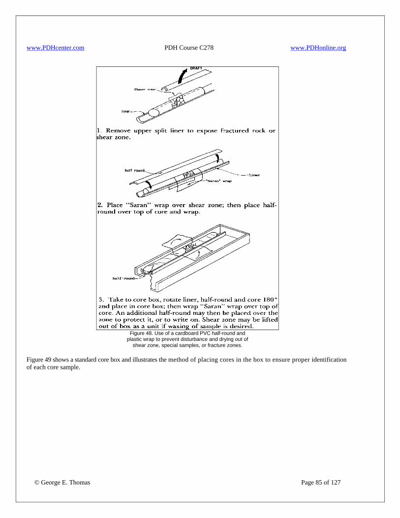
www.PDHcenter.com PDH Course C278 www.PDHonline.org
Figure 48. Use of a cardboard PVC half-round and
plastic wrap to prevent disturbance and drying out of shear zone, special samples, or fracture zones.
Figure 49 shows a standard core box and illustrates the method of placing cores in the box to ensure proper identification of each core sample.
© George E. Thomas Page 85 of 127
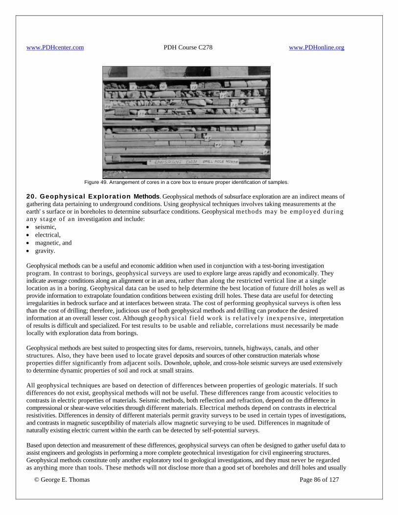
www.PDHcenter.com PDH Course C278 www.PDHonline.org
Figure 49. Arrangement of cores in a core box to ensure proper identification of samples.
20. Geophysical Exploration Methods. Geophysical methods of subsurface exploration are an indirect means of gathering data pertaining to underground conditions. Using geophysical techniques involves taking measurements at the earth' s surface or in boreholes to determine subsurface conditions. Geophysical methods may be employed dur ing any s tage of an investigation and include: • seismic, • electrical, • magnetic, and • gravity. Geophysical methods can be a useful and economic addition when used in conjunction with a test-boring investigation program. In contrast to borings, geophysical surveys are used to explore large areas rapidly and economically. They indicate average conditions along an alignment or in an area, rather than along the restricted vertical line at a single location as in a boring. Geophysical data can be used to help determine the best location of future drill holes as well as provide information to extrapolate foundation conditions between existing drill holes. These data are useful for detecting irregularities in bedrock surface and at interfaces between strata. The cost of performing geophysical surveys is often less than the cost of drilling; therefore, judicious use of both geophysical methods and drilling can produce the desired information at an overall lesser cost. Although geophysical f ie ld work is re la t ively inexpensive, interpretation of results is difficult and specialized. For test results to be usable and reliable, correlations must necessarily be made locally with exploration data from borings. Geophysical methods are best suited to prospecting sites for dams, reservoirs, tunnels, highways, canals, and other structures. Also, they have been used to locate gravel deposits and sources of other construction materials whose properties differ significantly from adjacent soils. Downhole, uphole, and cross-hole seismic surveys are used extensively to determine dynamic properties of soil and rock at small strains. All geophysical techniques are based on detection of differences between properties of geologic materials. If such differences do not exist, geophysical methods will not be useful. These differences range from acoustic velocities to contrasts in electric properties of materials. Seismic methods, both reflection and refraction, depend on the difference in compressional or shear-wave velocities through different materials. Electrical methods depend on contrasts in electrical resistivities. Differences in density of different materials permit gravity surveys to be used in certain types of investigations, and contrasts in magnetic susceptibility of materials allow magnetic surveying to be used. Differences in magnitude of naturally existing electric current within the earth can be detected by self-potential surveys.
© George E. Thomas Page 86 of 127
Based upon detection and measurement of these differences, geophysical surveys can often be designed to gather useful data to assist engineers and geologists in performing a more complete geotechnical investigation for civil engineering structures. Geophysical methods constitute only another exploratory tool to geological investigations, and they must never be regarded as anything more than tools. These methods will not disclose more than a good set of boreholes and drill holes and usually

www.PDHcenter.com PDH Course C278 www.PDHonline.org
© George E. Thomas Page 87 of 127
not as much, and they should not be used without specific and constant correlation with geologic information. A preliminary geologic investigation is essential before geophysical methods can be applied, since they require knowledge of certain general conditions of local geology. The most favorable condition occurs when high contrasts between geophysical properties exist, such as when rock underlies a shallow surficial deposit and the physical characteristics of the two are markedly different. Each type of geophysical survey has its capabilities and its limitations. Geophysical methods are now frequently used for preliminary investigations at potential damsites and at proposed locations of other types of water resources structures. The most extensive use of geophysical methods in the practice of civil engineering has been in the United States where the larger federal engineering organizations have used these methods regularly in preliminary exploration work. All the methods are subject to definite geological restrictions; rocks of essentially different physical character must be in contact, and the strata encountered must be fairly uniform with respect to their physical character. Low-density strata overlain by high density strata cannot be detected by any of the surface geophysical methods, although they can be detected by some of the borehole methods. Finally, all information obtained as a result of geophysical investigations must be studied and used only when properly correlated by a specialist with the maximum information available regarding local geologic conditions. Despite these qualifications and necessary restrictions, geophysical methods are a powerful and useful tool. The use of geophysics has increased when characterizing hazardous waste sites. Large areas can be tested to reduce the number of conventional borings and monitoring wells. Six methods are commonly used for ground-water contamination studies: • resistivity, • electromagnetic, • refraction and reflection, • magnetic, • ground-penetrating radar, • borehole geophysics. In many cases, water of differing chemistry or the presence of buried objects, such as tanks or drums, makes geophysical methods especially effective. For example, gravity surveys, which are not especially useful in civil engineering applications, may be useful at a site that contains buried storage tanks of unknown location. Expert systems have been developed to provide data on which forms of geophysics may be effective at a contamination site. A list of geophysical methods commonly used follows. Surface Geophysical and Other Techniques 1. Seismic Refraction 2. Seismic Reflection 3. Shear-Wave Surveys 4. Surface Wave Surveys 5. Vibration Surveys 6. Electrical-Resistivity Profiling Soundings Dipole-dipole 7. Electromagnetic Conductivity Profiling Soundings 8. Ground Probing Radar 9. Self-Potential Surveys 10. Magnetic Surveys 11. Gravity Surveys Borehole Geophysical and Other Techniques 1. Electrical Logging Spontaneous potential

www.PDHcenter.com PDH Course C278 www.PDHonline.org
© George E. Thomas Page 88 of 127
Single-point resistivity Multiple electrode arrays Micrologging Induction logging Borehole fluid resistivity 2. Nuclear Radiation Logging Gamma ray Gamma-gamma logging Neutron logging 3. Acoustic/Seismic Acoustic velocity Acoustic borehole logging Crosshole seismic Tomography 4. Optical Borehole Logging Television camera Film camera 5. Borehole Caliper Logger 6. Borehole Fluid Temperature Logger 7. Borehole Gravity Logger Tables 6 and 7 show application and limitations for use of some of these techniques. Table 6 shows surface methods, and table 7 shows borehole logging methods. Correlations have been made between rock rippability and seismic wave velocity. Figure 50 shows an example of such correlations for heavy duty ripper performance (ripper mounted on tracked bulldozer). Charts similar to that shown in figure 50 are available from various equipment manufacturers but must be used with extreme caution.
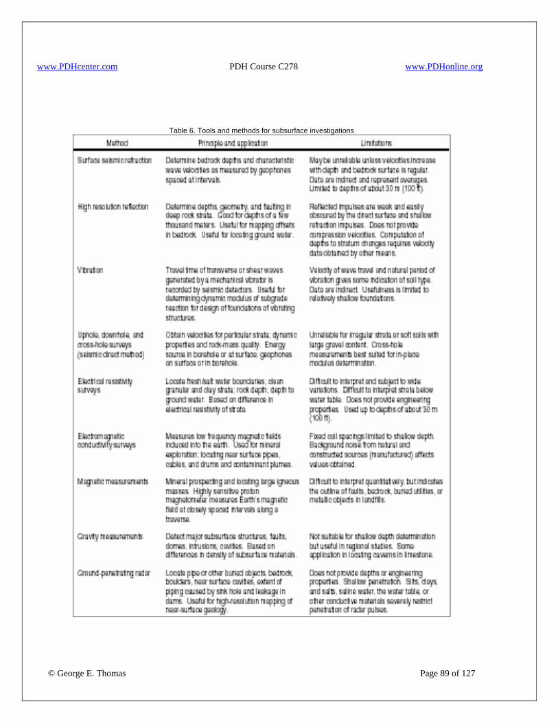
www.PDHcenter.com PDH Course C278 www.PDHonline.org
Table 6. Tools and methods for subsurface investigations
© George E. Thomas Page 89 of 127
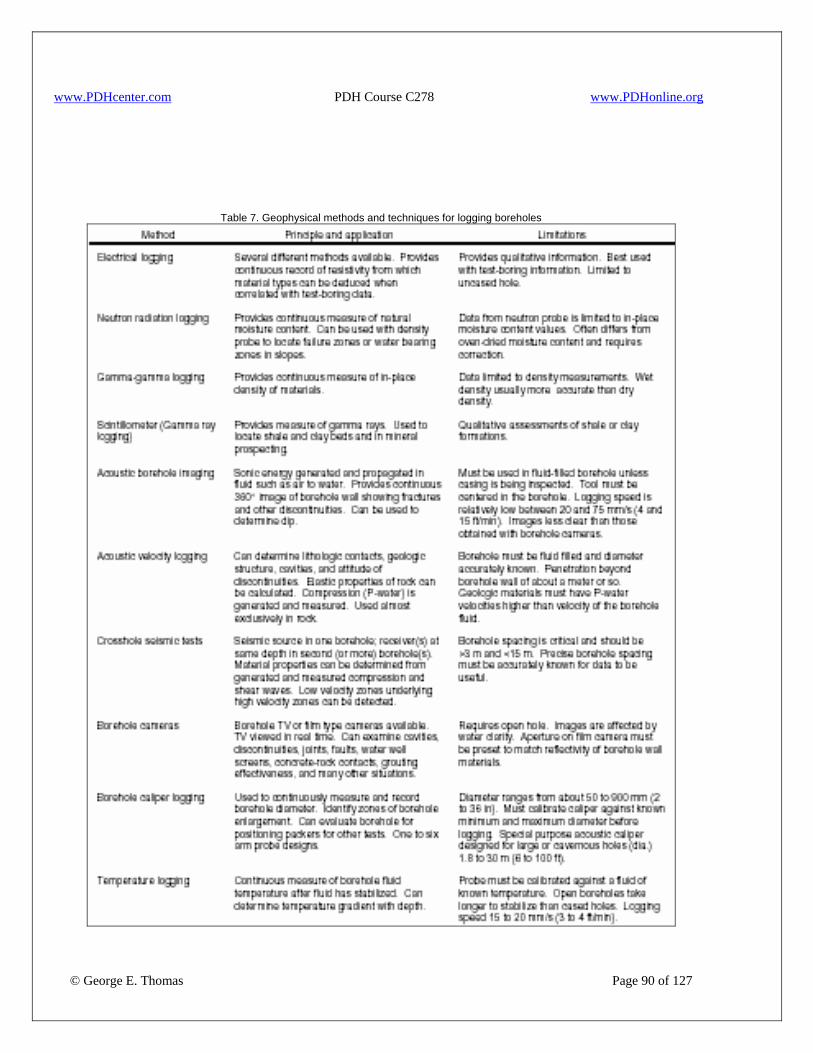
www.PDHcenter.com PDH Course C278 www.PDHonline.org
Table 7. Geophysical methods and techniques for logging boreholes
© George E. Thomas Page 90 of 127
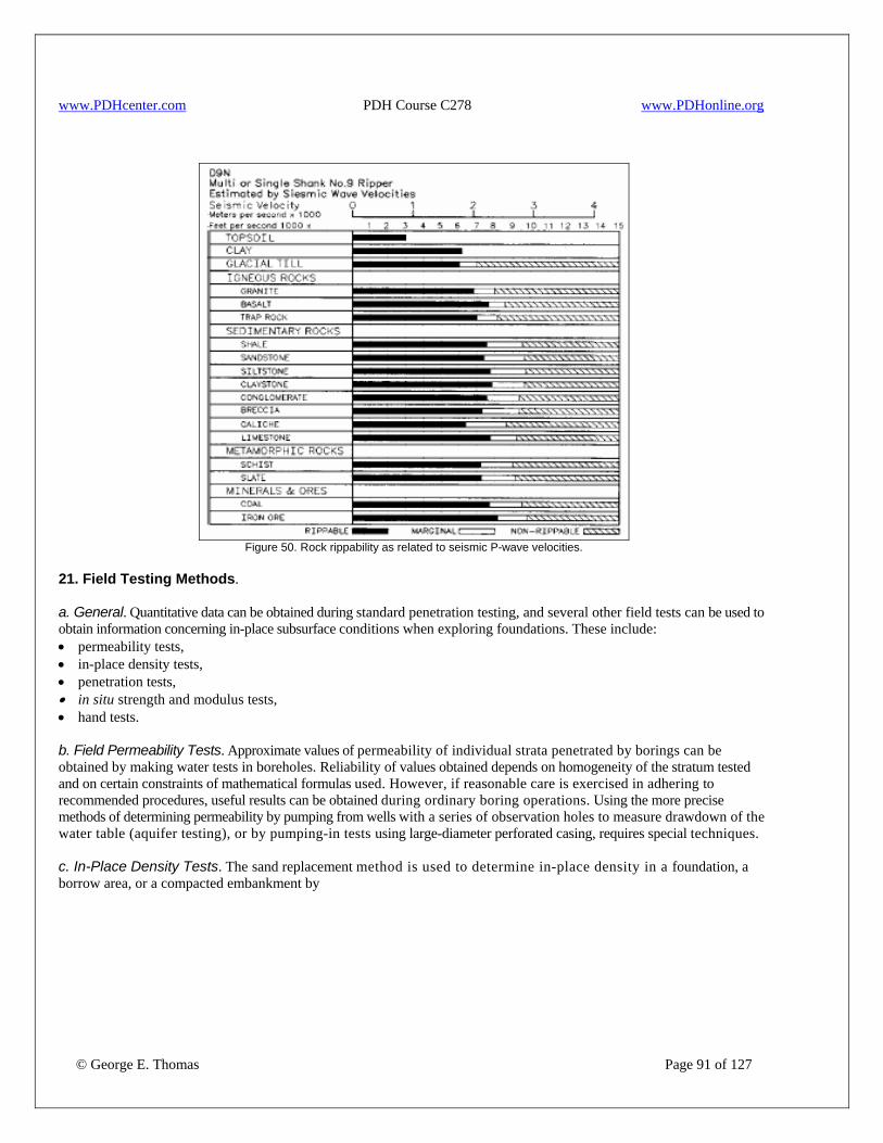
www.PDHcenter.com PDH Course C278 www.PDHonline.org
Figure 50. Rock rippability as related to seismic P-wave velocities.
21. Field Testing Methods. a. General. Quantitative data can be obtained during standard penetration testing, and several other field tests can be used to obtain information concerning in-place subsurface conditions when exploring foundations. These include: • permeability tests, • in-place density tests, • penetration tests, • in situ strength and modulus tests, • hand tests. b. Field Permeability Tests. Approximate values of permeability of individual strata penetrated by borings can be obtained by making water tests in boreholes. Reliability of values obtained depends on homogeneity of the stratum tested and on certain constraints of mathematical formulas used. However, if reasonable care is exercised in adhering to recommended procedures, useful results can be obtained during ordinary boring operations. Using the more precise methods of determining permeability by pumping from wells with a series of observation holes to measure drawdown of the water table (aquifer testing), or by pumping-in tests using large-diameter perforated casing, requires special techniques. c. In-Place Density Tests. The sand replacement method is used to determine in-place density in a foundation, a borrow area, or a compacted embankment by
© George E. Thomas Page 91 of 127
www.PDHcenter.com PDH Course C278 www.PDHonline.org
excavating a hole from a horizontal surface, determining the mass of material excavated, and determining the volume of the hole by filling it with calibrated sand. Water content of soil excavated from the hole is determined, and in-place dry density is calculated. In-place density data are often used in calculations to determine shrinkage or swell factors between borrow area excavation and compacted embankment volumes. In-place density tests can be performed in shallow foundations to evaluate bearing capacity for small structures. Various devices using replacement methods (i.e., water, balloons and water, oil) have been used to measure the volume of the test hole. Indirect methods such as the nuclear moisture and density gauge are also used to determine in-place density, but the sand replacement method is most common. If the soil to be tested contains appreciable coarse gravel and cobbles, in-place density is normally determined by use of test pits with water replacement. These large scale tests are expensive; normally, they only are performed when exploring critical coarse grained borrow materials and for construction control of rockfills and coarse shells of dams. The determination of in-place dry density and water content of a fairly deep foundation is often necessary. In this case, the sand density method requires excavating a deep test pit or test trench to gain access to the soils to be tested. Excavation of deep test pits or accessible shafts can be hampered by the presence of ground water, and special safety precautions are required. Most deep test shafts are reserved for critical explorations of coarse and cohesionless soils. Mechanical drilling and sampling methods have mostly replaced deep test shafts. Mechanical drilling and sampling, if performed correctly, can provide reliable information on in-place moisture and density of deep foundation soils. These data can be reliably obtained in the field and are extremely useful for design purposes. If mechanical drilling and sampling is performed, it is strongly recommended that average tube density be determined. d. Penetration Testing. 1. General. Data obtained from quasi-static or dynamic penetration tests can be used to estimate engineering properties of soils and to delineate subsurface stratigraphy. The most common tests employed are standard penetration and cone penetration tests (SPT and CPT tests). By evaluating resistance to penetration during the tests, engineering properties of compressibility and shear strength can be estimated. Also, test results can be compared and correlated to properties obtained from laboratory tests on undisturbed soil specimens. In many cases the number of undisturbed sampling holes may be reduced in favor of less expensive penetration tests to better interpret complex site stratigraphy. 2. Penetration Resistance and Sampling of Soils. The SPT test consists of determining the number of blows N, of a 140 lbm hammer dropping 30”, required to produce 1”of penetration of a standard 2” o. d. sampler into soil at the bottom of a prebored drill hole after the sampler is seated an initial 6”(fig. 51). The N value can be used to estimate strength and compressibility of sands, consistency of clays, and bearing capacities. A disturbed sample is retrieved in the 1-3/8” i.d. sampler barrel which allows for inspection, visual classification, and moisture content determination (fig. 52). The Government specifies a barrel with constant inside diameter of 1-3/8”, but most SPT barrels manufactured in the United States today are upset walled to 1-1/2” diameter to accommodate liners. The difference in SPT N value can vary 10 to 30 percent between different barrels. If critical studies are performed, the inside diameter of the barrel must be known so corrections can be made. Laboratory soil classification tests also can be performed on the soil sample. Normally, penetration tests are performed at 5’intervals or with changes in soil strata. For critical investigations, such as foundations for dams, testing may be performed more frequently, but normally the minimum testing interval is 2-1/2’ to prevent disturbance of soil to be tested in the next interval. The penetration resistance test is widely used to evaluate foundation conditions for investigations requiring drill holes. Penetration resistance obtained during field testing is inversely proportional to the energy delivered to the sampler system by the driving system. Research has shown that the wide variety of equipment available and in use in the United States results in large variations in energy delivery and consequently in N (blow count) values. Procedures require the use of safety hammers with the rope and cathead method. The drill rod energy delivered by safety hammers ranges from 60 to 70 percent of free fall hammer energy and is now considered the standard target range for SPT in the United States. Energy delivered by automatic and manual trip hammer systems is more reproducible, and possibly higher, because the influence of rope condition, method of rope release from the cathead, and friction in the mast sheave are all bypassed. Drill rod energy transmission ranges from 90 to 95 percent for those automatic trip hammers for which energy measurements have been made. Using automatic hammer systems enhances test reproducibility. These hammer systems can, however, only be approved for use after energy delivery and transmission characteristics are known. On critical programs, such as liquefaction studies, adjustment for higher energy of automatic hammers may be required.
© George E. Thomas Page 92 of 127
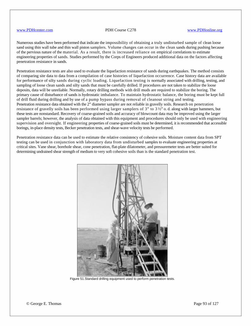
www.PDHcenter.com PDH Course C278 www.PDHonline.org
Numerous studies have been performed that indicate the impossibility of obtaining a truly undisturbed sample of clean loose sand using thin wall tube and thin wall piston samplers. Volume changes can occur in the clean sands during pushing because of the pervious nature of the material. As a result, there is increased reliance on empirical correlations to estimate engineering properties of sands. Studies performed by the Corps of Engineers produced additional data on the factors affecting penetration resistance in sands. Penetration resistance tests are also used to evaluate the liquefaction resistance of sands during earthquakes. The method consists of comparing site data to data from a compilation of case histories of liquefaction occurrence. Case history data are available for performance of silty sands during cyclic loading. Liquefaction testing is normally associated with drilling, testing, and sampling of loose clean sands and silty sands that must be carefully drilled. If procedures are not taken to stabilize the loose deposits, data will be unreliable. Normally, rotary drilling methods with drill muds are required to stabilize the boring. The primary cause of disturbance of sands is hydrostatic imbalance. To maintain hydrostatic balance, the boring must be kept full of drill fluid during drilling and by use of a pump bypass during removal of cleanout string and testing. Penetration resistance data obtained with the 2” diameter sampler are not reliable in gravelly soils. Research on penetration resistance of gravelly soils has been performed using larger samplers of 3” to 3 ½” o. d. along with larger hammers, but these tests are nonstandard. Recovery of coarse-grained soils and accuracy of blowcount data may be improved using the larger sampler barrels; however, the analysis of data obtained with this equipment and procedures should only be used with engineering supervision and oversight. If engineering properties of coarse-grained soils must be determined, it is recommended that accessible borings, in-place density tests, Becker penetration tests, and shear-wave velocity tests be performed. Penetration resistance data can be used to estimate the relative consistency of cohesive soils. Moisture content data from SPT testing can be used in conjunction with laboratory data from undisturbed samples to evaluate engineering properties at critical sites. Vane shear, borehole shear, cone penetration, flat-plate dilatometer, and pressuremeter tests are better suited for determining undrained shear strength of medium to very soft cohesive soils than is the standard penetration test.
Figure 51.Standard drilling equipment used to perform penetration tests.
© George E. Thomas Page 93 of 127
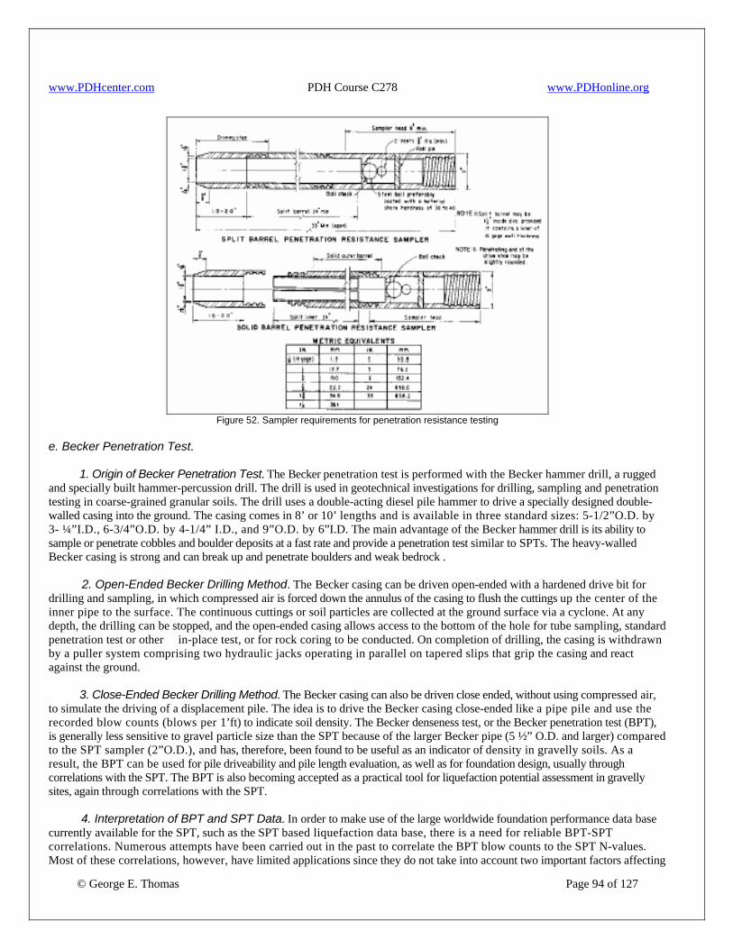
www.PDHcenter.com PDH Course C278 www.PDHonline.org
Figure 52. Sampler requirements for penetration resistance testing
e. Becker Penetration Test. 1. Origin of Becker Penetration Test. The Becker penetration test is performed with the Becker hammer drill, a rugged and specially built hammer-percussion drill. The drill is used in geotechnical investigations for drilling, sampling and penetration testing in coarse-grained granular soils. The drill uses a double-acting diesel pile hammer to drive a specially designed double-walled casing into the ground. The casing comes in 8’ or 10’ lengths and is available in three standard sizes: 5-1/2”O.D. by 3- ¼”I.D., 6-3/4”O.D. by 4-1/4” I.D., and 9”O.D. by 6”I.D. The main advantage of the Becker hammer drill is its ability to sample or penetrate cobbles and boulder deposits at a fast rate and provide a penetration test similar to SPTs. The heavy-walled Becker casing is strong and can break up and penetrate boulders and weak bedrock . 2. Open-Ended Becker Drilling Method. The Becker casing can be driven open-ended with a hardened drive bit for drilling and sampling, in which compressed air is forced down the annulus of the casing to flush the cuttings up the center of the inner pipe to the surface. The continuous cuttings or soil particles are collected at the ground surface via a cyclone. At any depth, the drilling can be stopped, and the open-ended casing allows access to the bottom of the hole for tube sampling, standard penetration test or other in-place test, or for rock coring to be conducted. On completion of drilling, the casing is withdrawn by a puller system comprising two hydraulic jacks operating in parallel on tapered slips that grip the casing and react against the ground. 3. Close-Ended Becker Drilling Method. The Becker casing can also be driven close ended, without using compressed air, to simulate the driving of a displacement pile. The idea is to drive the Becker casing close-ended like a pipe pile and use the recorded blow counts (blows per 1’ft) to indicate soil density. The Becker denseness test, or the Becker penetration test (BPT), is generally less sensitive to gravel particle size than the SPT because of the larger Becker pipe (5 ½” O.D. and larger) compared to the SPT sampler (2”O.D.), and has, therefore, been found to be useful as an indicator of density in gravelly soils. As a result, the BPT can be used for pile driveability and pile length evaluation, as well as for foundation design, usually through correlations with the SPT. The BPT is also becoming accepted as a practical tool for liquefaction potential assessment in gravelly sites, again through correlations with the SPT.
© George E. Thomas Page 94 of 127
4. Interpretation of BPT and SPT Data. In order to make use of the large worldwide foundation performance data base currently available for the SPT, such as the SPT based liquefaction data base, there is a need for reliable BPT-SPT correlations. Numerous attempts have been carried out in the past to correlate the BPT blow counts to the SPT N-values. Most of these correlations, however, have limited applications since they do not take into account two important factors affecting

www.PDHcenter.com PDH Course C278 www.PDHonline.org
the BPT blow counts: the variable energy output of the diesel hammer used in the Becker system and the soil friction acting on the Becker casing during driving. To overcome the variable hammer energy problem in the BPT, a method was proposed of using the measured peak bounce-chamber pressures at the top of the double-acting diesel hammer to correct the measured blow counts to a so-called "constant full combustion condition". The corrected BPT blow counts can be correlated to corrected SPT blow counts. Although an improvement over existing BPT-SPT correlations, this method still has serious limitations. The bounce-chamber, pressure-correction method cannot capture all the important variables affecting the BPT blow count, and the BPT-SPT correlation does not consider casing friction in the BPT. f. Cone Penetration Tests. Cone Penetration testing was developed in the Netherlands for rapid penetration testing of low density estuarine deposits. The procedure consists of measuring the resistance of a 600 apex angle cone, with 1000 mm2 projected surface area, being pushed into the soil at a controlled rate of 20 mm/s. During most cone tests the force exerted on a cylindrical friction sleeve located behind the tip is also measured. Cone testing is performed for rapid delineation of site stratigraphy and estimation of strength, compressibility, pile capacity and liquefaction resistance. With the introduction of electronic cone penetrometers, penetration resistance data can be collected at intervals as close as 3/4” to provide an excellent record of subsurface stratigraphy. As shown on the example, figure 53, drained behavior in cohesionless deposits results in significantly higher cone tip resistance than in undrained clays. The resulting data trace accurately delineates bedding in layered deposits. The bottom layer, of the example figure, is a lacustrine deposit under a dam where seasonal gradational differences in the deposit are delineated with the cone. Additional sensors can be added to the cone body to obtain records of: • pore pressure, • cone inclination, • temperature, • electrical resistivity or conductivity, • seismic wave velocity by use of geophones. Using the piezocone, soundings can be stopped in sand layers and hydrostatic pressures can be determined.
© George E. Thomas Page 95 of 127
Advantages of cone testing include the rapid rate of testing, ability to obtain excellent soil stratigraphy data, and repeatability of test data. Disadvantages of cone penetration testing are the inability to obtain a soil sample and to test firmer soils because of the large thrust required to push the cone into the soil. On favorable sites, having good access and moderate to soft soil conditions, production can reach 200’ to 400’ per day with resulting minimal exploration costs per meter of sounding. On investigations for significant structures, such as dams, the inability to obtain samples requires that site-specific correlation be performed with undisturbed sampling. If the cone is used, the number of expensive sampling holes may be reduced. Another disadvantage of cone penetration soundings is that backfill grouting of cone holes is difficult and requires specialized equipment. Backfilling may be required when sounding through water retaining embankments and hazardous waste sites.
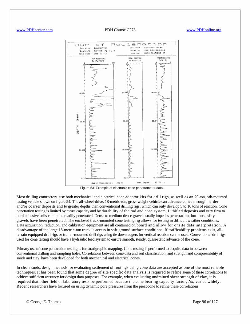
www.PDHcenter.com PDH Course C278 www.PDHonline.org
Figure 53. Example of electronic cone penetrometer data.
Most drilling contractors use both mechanical and electrical cone adaptor kits for drill rigs, as well as an 20-ton, cab-mounted testing vehicle shown on figure 54. The all-wheel-drive, 18-metric-ton, gross-weight vehicle can advance cones through harder and/or coarser deposits and to greater depths than conventional drilling rigs, which can only develop 5 to 10 tons of reaction. Cone penetration testing is limited by thrust capacity and by durability of the rod and cone system. Lithified deposits and very firm to hard cohesive soils cannot be readily penetrated. Dense to medium dense gravel usually impedes penetration, but loose silty gravels have been penetrated. The enclosed truck-mounted cone testing rig allows for testing in difficult weather conditions. Data acquisition, reduction, and calibration equipment are all contained on board and allow for onsite data interpretation. A disadvantage of the large 18-metric-ton truck is access in soft ground surface conditions. If trafficability problems exist, all-terrain equipped drill rigs or trailer-mounted drill rigs using tie down augers for vertical reaction can be used. Conventional drill rigs used for cone testing should have a hydraulic feed system to ensure smooth, steady, quasi-static advance of the cone. Primary use of cone penetration testing is for stratigraphic mapping. Cone testing is performed to acquire data in between conventional drilling and sampling holes. Correlations between cone data and soil classification, and strength and compressibility of sands and clay, have been developed for both mechanical and electrical cones. In clean sands, design methods for evaluating settlement of footings using cone data are accepted as one of the most reliable techniques. It has been found that some degree of site specific data analysis is required to refine some of these correlations to achieve sufficient accuracy for design data purposes. For example, when evaluating undrained shear strength of clay, it is required that other field or laboratory tests be performed because the cone bearing capacity factor, Nk, varies widely. Recent researchers have focused on using dynamic pore pressures from the piezocone to refine these correlations.
© George E. Thomas Page 96 of 127
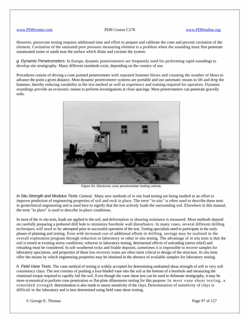
www.PDHcenter.com PDH Course C278 www.PDHonline.org
However, piezocone testing requires additional time and effort to prepare and calibrate the cone and prevent cavitation of the element. Cavitation of the saturated pore pressure measuring element is a problem when the sounding must first penetrate unsaturated zones or sands near the surface which dilate and cavitate the system. g. Dynamic Penetrometers. In Europe, dynamic penetrometers are frequently used for performing rapid soundings to develop site stratigraphy. Many different standards exist, depending on the country of use. Procedures consist of driving a cone pointed penetrometer with repeated hammer blows and counting the number of blows to advance the point a given distance. Most dynamic penetrometer systems are portable and use automatic means to lift and drop the hammer, thereby reducing variability in the test method as well as experience and training required for operators. Dynamic soundings provide an economic means to perform investigations at close spacings. Most penetrometers can penetrate gravelly soils.
Figure 54. Electronic cone penetrometer testing vehicle.
In Situ Strength and Modulus Tests. General. Many new methods of in situ load testing are being studied in an effort to improve prediction of engineering properties of soil and rock in place. The term "in-situ" is often used to describe these tests in geotechnical engineering and is used here to signify that the test actively loads the surrounding soil. Elsewhere in this manual, the term "in place" is used to describe in-place conditions. In most of the in situ tests, loads are applied to the soil, and deformation or shearing resistance is measured. Most methods depend on carefully preparing a prebored drill hole to minimize borehole wall disturbance. In many cases, several different drilling techniques will need to be attempted prior to successful operation of the test. Testing specialists need to participate in the early phases of planning and testing. Even with increased cost of additional efforts in drilling, savings may be realized in the overall exploration program through reduction in laboratory or other in situ testing. The advantage of in situ tests is that the soil is tested at existing stress conditions; whereas in laboratory testing, detrimental effects of unloading (stress relief) and reloading must be considered. In soft weathered rocks and friable deposits, sometimes it is impossible to recover samples for laboratory specimens, and properties of these low recovery zones are often most critical to design of the structure. In situ tests offer the means by which engineering properties may be obtained in the absence of available samples for laboratory testing.
© George E. Thomas Page 97 of 127
h. Field Vane Tests. The vane method of testing is widely accepted for determining undrained shear strength of soft to very soft consistency clays. The test consists of pushing a four-bladed vane into the soil at the bottom of a borehole and measuring the rotational torque required to rapidly fail the soil. Even though the vane shear test can be used to delineate stratigraphy, it may be more economical to perform cone penetration or flat-plate dilatometer testing for this purpose. In most vane shear tes t ing, a remolded s trength determination is also made to assess sensitivity of the clays. Determination of sensitivity of clays is difficult in the laboratory and is best determined using field vane shear testing.

www.PDHcenter.com PDH Course C278 www.PDHonline.org
Vane shear testing requires a rotary drill rig to drill and clean the boring and to press the vane into undisturbed soil. The Government has modified the BX casing housing of the vane and rods to act as a rotary drill string. During drilling, the vane is retracted inside the BX cutting bit. This modification reduces hole disturbance in very soft clays and precludes the need to withdraw the entire drill string and lower it again every time a vane test is performed. Determination of rod friction is easily accomplished using a vane shear device which is equipped with a special vane slip coupling system. j. Pressuremeter Testing. Pressuremeter tests are performed to characterize the stress-strain behavior of soil and rock in place. Tests are performed by measuring the pressure and resulting volume change increments of a cylindrical expandable measuring cell which is inserted into a carefully prepared borehole (fig. 55). The measuring cell or probe is typically inserted into a prebored drill hole; but in some instances, it is advanced by self-boring or driving. Test procedures are still under development, but satisfactory procedures for interim use are given in ASTM procedure D 4719. Pressuremeter tests can be used to determine the in-place modulus of deformation of a wide variety of soils and rock for which undisturbed sampling and laboratory testing are difficult. The data are primarily used to evaluate anticipated structural settlements. Usually, testing is performed with pressure increments applied at 1 minute intervals, which results in undrained loading of fine-grained soils. Undrained strength of cohesive soils can be estimated from the limit pressure (pressure at infinite expansion), but requires extrapolation of test data. The pressuremeter is the only reliable method of determining the in-place friction angle of sands using stress-dilatency theory. However, use of a self-boring pressuremeter is required in saturated loose sands to minimize drilling disturbance. Rock pressuremeters (dilatometers) with maximum pressure capability approaching 5,000 bf/in2 can be used to evaluate deformation modulus in hard rock to soft rock and in areas of low recovery. Strength interpretation of both hard rock and softer rock is difficult, highly theoretical, and requires interpretations of stress-strain paths. Strength test data interpretation in cemented soils and soft or fractured rock is especially difficult. As a result of these difficulties, the Government uses the rock dilatometer primarily to evaluate deformation modulus, and other field and laboratory tests are performed to determine strength. Pressuremeter testing has been performed in gravelly soils by driving a slotted AW casing to protect the pressuremeter, but effects of driving displacements in gravel are not fully understood.
© George E. Thomas Page 98 of 127
Pressuremeter testing in soils requires exacting execution of drilling to: (1) minimize disturbance of the borehole wall and (2) provide a borehole diameter within allowable tolerance. Test procedures require that the borehole be no smaller than 97 percent of probe diameter or 20 percent greater than probe diameter when testing soils. Even tighter borehole diameter requirements are required for rock dilatometers. Since testing is typically performed in materials which are difficult to sample, a variety of drilling methods may need to be attempted to achieve success. In very soft clays and loose saturated sands the self-boring pressuremeter is recommended. Two self-boring pressuremeters are shown in figure 56. A recent trend in self-boring pressuremeters is using jetting instead of rock bitting for hole advancement. If jetting is used, the pressuremeter body should be equipped with fluid pressure sensors to ensure that circulation is maintained. Wall disturbance can be evaluated from the pressure-volume data. Testing duration can be up to 1 to 2 hours per interval. Although pressuremeter testing is one of the more expensive in-place tests, the testing is still performed at less cost than obtaining undisturbed samples and performing laboratory testing.
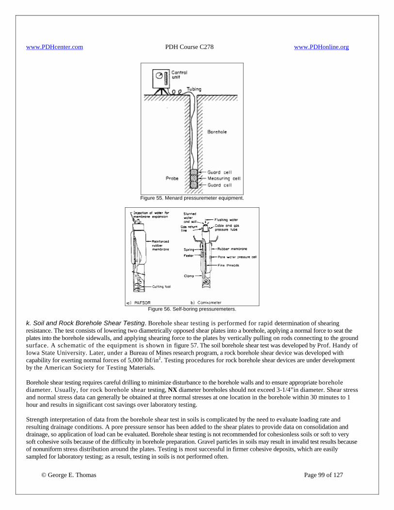
www.PDHcenter.com PDH Course C278 www.PDHonline.org
Figure 55. Menard pressuremeter equipment.
Figure 56. Self-boring pressuremeters.
k. Soil and Rock Borehole Shear Testing. Borehole shear testing is performed for rapid determination of shearing resistance. The test consists of lowering two diametrically opposed shear plates into a borehole, applying a normal force to seat the plates into the borehole sidewalls, and applying shearing force to the plates by vertically pulling on rods connecting to the ground surface. A schematic of the equipment is shown in figure 57. The soil borehole shear test was developed by Prof. Handy of Iowa State University. Later, under a Bureau of Mines research program, a rock borehole shear device was developed with capability for exerting normal forces of 5,000 lbf/in2. Testing procedures for rock borehole shear devices are under development by the American Society for Testing Materials. Borehole shear testing requires careful drilling to minimize disturbance to the borehole walls and to ensure appropriate borehole diameter. Usually, for rock borehole shear testing, NX diameter boreholes should not exceed 3-1/4”in diameter. Shear stress and normal stress data can generally be obtained at three normal stresses at one location in the borehole within 30 minutes to 1 hour and results in significant cost savings over laboratory testing.
© George E. Thomas Page 99 of 127
Strength interpretation of data from the borehole shear test in soils is complicated by the need to evaluate loading rate and resulting drainage conditions. A pore pressure sensor has been added to the shear plates to provide data on consolidation and drainage, so application of load can be evaluated. Borehole shear testing is not recommended for cohesionless soils or soft to very soft cohesive soils because of the difficulty in borehole preparation. Gravel particles in soils may result in invalid test results because of nonuniform stress distribution around the plates. Testing is most successful in firmer cohesive deposits, which are easily sampled for laboratory testing; as a result, testing in soils is not performed often.
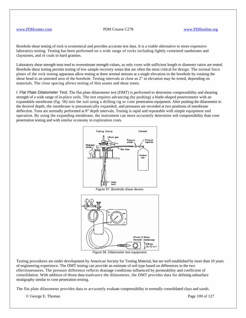
www.PDHcenter.com PDH Course C278 www.PDHonline.org
Borehole shear testing of rock is economical and provides accurate test data. It is a viable alternative to more expensive laboratory testing. Testing has been performed on a wide range of rocks including lightly cemented sandstones and claystones, and of coals to hard granites. Laboratory shear strength tests tend to overestimate strength values, as only cores with sufficient length to diameter ratios are tested. Borehole shear testing permits testing of low sample recovery zones that are often the most critical for design. The normal force plates of the rock testing apparatus allow testing at three normal stresses at a single elevation in the borehole by rotating the shear head to an untested area of the borehole. Testing intervals as close as 2” in elevation may be tested, depending on materials. The close spacing allows testing of thin seams and shear zones. l. Flat Plate Dilatometer Test. The flat plate dilatometer test (DMT) is performed to determine compressibility and shearing strength of a wide range of in-place soils. The test requires advancing (by pushing) a blade-shaped penetrometer with an expandable membrane (fig. 58) into the soil using a drilling rig or cone penetration equipment. After pushing the dilatometer to the desired depth, the membrane is pneumatically expanded, and pressures are recorded at two positions of membrane deflection. Tests are normally performed at 8” depth intervals. Testing is rapid and repeatable with simple equipment and operation. By using the expanding membrane, the instrument can more accurately determine soil compressibility than cone penetration testing and with similar economy in exploration costs.
Figure 57. Borehole shear device.
Figure 58. Dilatometer test equipment.
Testing procedures are under development by American Society for Testing Material, but are well established by more than 10 years of engineering experience. The DMT testing can provide an estimate of soil type based on differences in the two eflectionessures. The pressure difference reflects drainage conditions influenced by permeability and coefficient of consolidation. With addition of thrust data toadvance the dilatometer, the DMT provides data for defining subsurface stratigraphy similar to cone penetration testing.
© George E. Thomas Page 100 of 127
The flat plate dilatometer provides data to accurately evaluate compressibility in normally consolidated clays and sands.
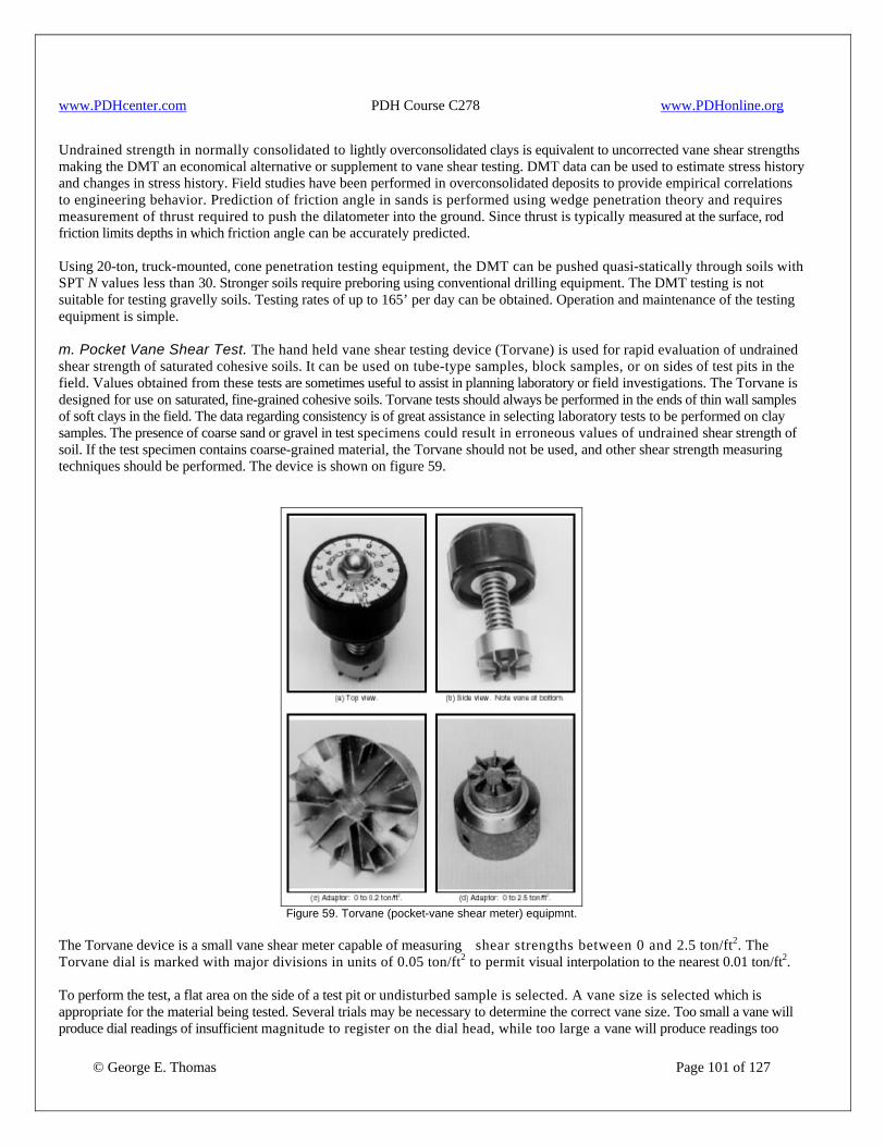
www.PDHcenter.com PDH Course C278 www.PDHonline.org
Undrained strength in normally consolidated to lightly overconsolidated clays is equivalent to uncorrected vane shear strengths making the DMT an economical alternative or supplement to vane shear testing. DMT data can be used to estimate stress history and changes in stress history. Field studies have been performed in overconsolidated deposits to provide empirical correlations to engineering behavior. Prediction of friction angle in sands is performed using wedge penetration theory and requires measurement of thrust required to push the dilatometer into the ground. Since thrust is typically measured at the surface, rod friction limits depths in which friction angle can be accurately predicted. Using 20-ton, truck-mounted, cone penetration testing equipment, the DMT can be pushed quasi-statically through soils with SPT N values less than 30. Stronger soils require preboring using conventional drilling equipment. The DMT testing is not suitable for testing gravelly soils. Testing rates of up to 165’ per day can be obtained. Operation and maintenance of the testing equipment is simple. m. Pocket Vane Shear Test. The hand held vane shear testing device (Torvane) is used for rapid evaluation of undrained shear strength of saturated cohesive soils. It can be used on tube-type samples, block samples, or on sides of test pits in the field. Values obtained from these tests are sometimes useful to assist in planning laboratory or field investigations. The Torvane is designed for use on saturated, fine-grained cohesive soils. Torvane tests should always be performed in the ends of thin wall samples of soft clays in the field. The data regarding consistency is of great assistance in selecting laboratory tests to be performed on clay samples. The presence of coarse sand or gravel in test specimens could result in erroneous values of undrained shear strength of soil. If the test specimen contains coarse-grained material, the Torvane should not be used, and other shear strength measuring techniques should be performed. The device is shown on figure 59.
Figure 59. Torvane (pocket-vane shear meter) equipmnt.
The Torvane device is a small vane shear meter capable of measuring shear strengths between 0 and 2.5 ton/ft2. The Torvane dial is marked with major divisions in units of 0.05 ton/ft2 to permit visual interpolation to the nearest 0.01 ton/ft2.
© George E. Thomas Page 101 of 127
To perform the test, a flat area on the side of a test pit or undisturbed sample is selected. A vane size is selected which is appropriate for the material being tested. Several trials may be necessary to determine the correct vane size. Too small a vane will produce dial readings of insufficient magnitude to register on the dial head, while too large a vane will produce readings too
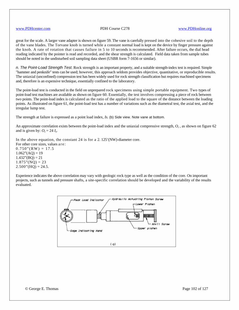
www.PDHcenter.com PDH Course C278 www.PDHonline.org
great for the scale. A larger vane adapter is shown on figure 59. The vane is carefully pressed into the cohesive soil to the depth of the vane blades. The Torvane knob is turned while a constant normal load is kept on the device by finger pressure against the knob. A rate of rotation that causes failure in 5 to 10 seconds is recommended. After failure occurs, the dial head reading indicated by the pointer is read and recorded, and the shear strength is calculated. Field data taken from sample tubes should be noted in the undisturbed soil sampling data sheet (USBR form 7-1656 or similar). n. The Point-Load Strength Test. Rock strength is an important property, and a suitable strength-index test is required. Simple "hammer and penknife" tests can be used; however, this approach seldom provides objective, quantitative, or reproducible results. The uniaxial (unconfined) compression test has been widely used for rock strength classification but requires machined specimens and, therefore is an expensive technique, essentially confined to the laboratory. The point-load test is conducted in the field on unprepared rock specimens using simple portable equipment. Two types of point-load test machines are available as shown on figure 60. Essentially, the test involves compressing a piece of rock between two points. The point-load index is calculated as the ratio of the applied load to the square of the distance between the loading points. As illustrated on figure 61, the point-load test has a number of variations such as the diametral test, the axial test, and the irregular lump test. The strength at failure is expressed as a point load index, Is. (b) Side view. Note vane at bottom. An approximate correlation exists between the point-load index and the uniaxial compressive strength, Oc , as shown on figure 62 and is given by: Oc = 24 Is. In the above equation, the constant 24 is for a 2. 125’(NW)-diameter core. For other core sizes, values a r e : 0 .750”(RW) = 17 .5 1.062”(AQ) = 19 1.432”(BQ) = 21 1.875”(NQ) = 23 2.500”(HQ) = 24.5. Experience indicates the above correlation may vary with geologic rock type as well as the condition of the core. On important projects, such as tunnels and pressure shafts, a site-specific correlation should be developed and the variability of the results evaluated.
© George E. Thomas Page 102 of 127
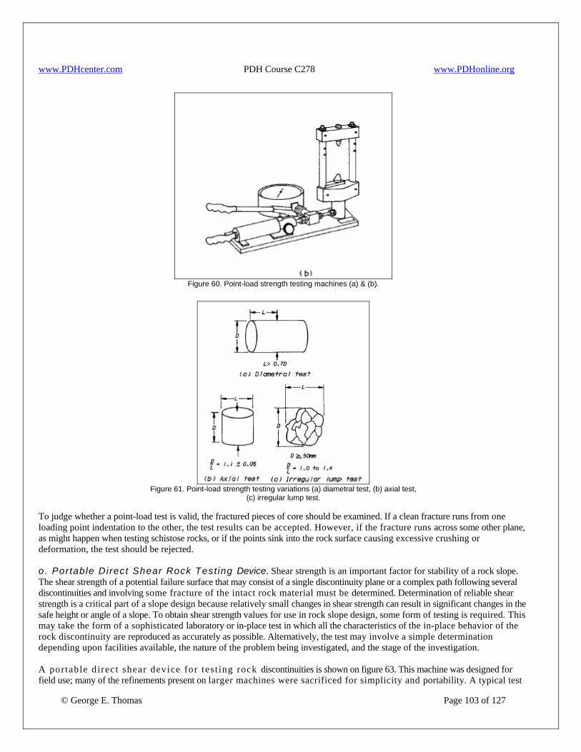
www.PDHcenter.com PDH Course C278 www.PDHonline.org
Figure 60. Point-load strength testing machines (a) & (b).
Figure 61. Point-load strength testing variations (a) diametral test, (b) axial test,
(c) irregular lump test.
To judge whether a point-load test is valid, the fractured pieces of core should be examined. If a clean fracture runs from one loading point indentation to the other, the test results can be accepted. However, if the fracture runs across some other plane, as might happen when testing schistose rocks, or if the points sink into the rock surface causing excessive crushing or deformation, the test should be rejected. o. Portable Direct Shear Rock Test ing Device. Shear strength is an important factor for stability of a rock slope. The shear strength of a potential failure surface that may consist of a single discontinuity plane or a complex path following several discontinuities and involving some fracture of the intact rock material must be determined. Determination of reliable shear strength is a critical part of a slope design because relatively small changes in shear strength can result in significant changes in the safe height or angle of a slope. To obtain shear strength values for use in rock slope design, some form of testing is required. This may take the form of a sophisticated laboratory or in-place test in which all the characteristics of the in-place behavior of the rock discontinuity are reproduced as accurately as possible. Alternatively, the test may involve a simple determination depending upon facilities available, the nature of the problem being investigated, and the stage of the investigation.
© George E. Thomas Page 103 of 127
A portable d irect shear device for tes t ing rock discontinuities is shown on figure 63. This machine was designed for field use; many of the refinements present on larger machines were sacrificed for simplicity and portability. A typical test
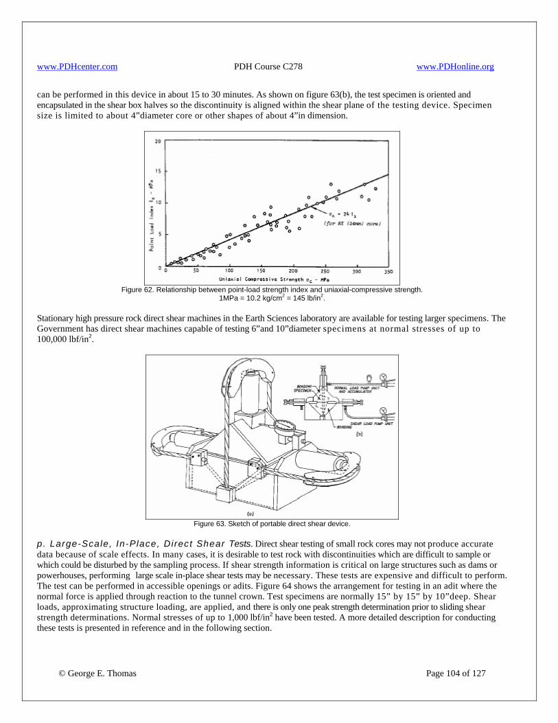
www.PDHcenter.com PDH Course C278 www.PDHonline.org
can be performed in this device in about 15 to 30 minutes. As shown on figure 63(b), the test specimen is oriented and encapsulated in the shear box halves so the discontinuity is aligned within the shear plane of the testing device. Specimen size is limited to about 4”diameter core or other shapes of about 4”in dimension.
Figure 62. Relationship between point-load strength index and uniaxial-compressive strength.
1MPa = 10.2 kg/cm2 = 145 lb/in2. Stationary high pressure rock direct shear machines in the Earth Sciences laboratory are available for testing larger specimens. The Government has direct shear machines capable of testing 6”and 10”diameter specimens at normal stresses of up to 100,000 lbf/in2.
Figure 63. Sketch of portable direct shear device.
p. Large-Scale, In-Place, Direct Shear Tests. Direct shear testing of small rock cores may not produce accurate data because of scale effects. In many cases, it is desirable to test rock with discontinuities which are difficult to sample or which could be disturbed by the sampling process. If shear strength information is critical on large structures such as dams or powerhouses, performing large scale in-place shear tests may be necessary. These tests are expensive and difficult to perform. The test can be performed in accessible openings or adits. Figure 64 shows the arrangement for testing in an adit where the normal force is applied through reaction to the tunnel crown. Test specimens are normally 15” by 15” by 10”deep. Shear loads, approximating structure loading, are applied, and there is only one peak strength determination prior to sliding shear strength determinations. Normal stresses of up to 1,000 lbf/in2 have been tested. A more detailed description for conducting these tests is presented in reference and in the following section.
© George E. Thomas Page 104 of 127
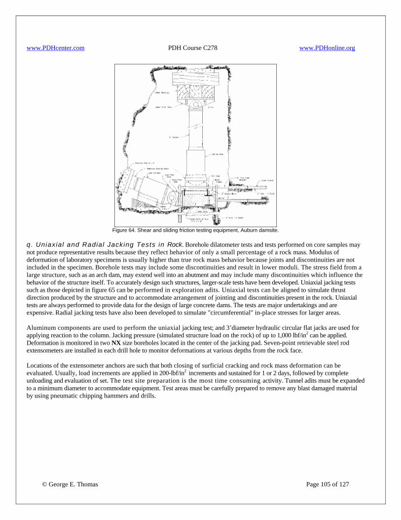
www.PDHcenter.com PDH Course C278 www.PDHonline.org
Figure 64. Shear and sliding friction testing equipment, Auburn damsite.
q. Uniaxial and Radial Jacking Tests in Rock. Borehole dilatometer tests and tests performed on core samples may not produce representative results because they reflect behavior of only a small percentage of a rock mass. Modulus of deformation of laboratory specimens is usually higher than true rock mass behavior because joints and discontinuities are not included in the specimen. Borehole tests may include some discontinuities and result in lower moduli. The stress field from a large structure, such as an arch dam, may extend well into an abutment and may include many discontinuities which influence the behavior of the structure itself. To accurately design such structures, larger-scale tests have been developed. Uniaxial jacking tests such as those depicted in figure 65 can be performed in exploration adits. Uniaxial tests can be aligned to simulate thrust direction produced by the structure and to accommodate arrangement of jointing and discontinuities present in the rock. Uniaxial tests are always performed to provide data for the design of large concrete dams. The tests are major undertakings and are expensive. Radial jacking tests have also been developed to simulate "circumferential" in-place stresses for larger areas. Aluminum components are used to perform the uniaxial jacking test; and 3’diameter hydraulic circular flat jacks are used for applying reaction to the column. Jacking pressure (simulated structure load on the rock) of up to 1,000 lbf/in2 can be applied. Deformation is monitored in two NX size boreholes located in the center of the jacking pad. Seven-point retrievable steel rod extensometers are installed in each drill hole to monitor deformations at various depths from the rock face. Locations of the extensometer anchors are such that both closing of surficial cracking and rock mass deformation can be evaluated. Usually, load increments are applied in 200-lbf/in2 increments and sustained for 1 or 2 days, followed by complete unloading and evaluation of set. The test site preparation is the most time consuming activity. Tunnel adits must be expanded to a minimum diameter to accommodate equipment. Test areas must be carefully prepared to remove any blast damaged material by using pneumatic chipping hammers and drills.
© George E. Thomas Page 105 of 127
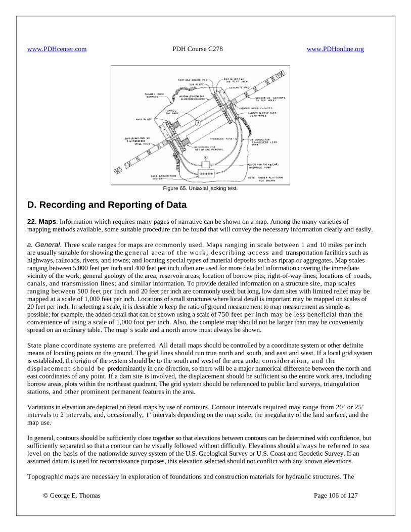
www.PDHcenter.com PDH Course C278 www.PDHonline.org
Figure 65. Uniaxial jacking test.
D. Recording and Reporting of Data 22. Maps. Information which requires many pages of narrative can be shown on a map. Among the many varieties of mapping methods available, some suitable procedure can be found that will convey the necessary information clearly and easily. a. General. Three scale ranges for maps are commonly used. Maps ranging in scale between 1 and 10 miles per inch are usually suitable for showing the general area of the work; descr ib ing access and transportation facilities such as highways, railroads, rivers, and towns; and locating special types of material deposits such as riprap or aggregates. Map scales ranging between 5,000 feet per inch and 400 feet per inch often are used for more detailed information covering the immediate vicinity of the work; general geology of the area; reservoir areas; location of borrow pits; right-of-way lines; locations of roads, canals, and transmission lines; and similar information. To provide detailed information on a structure site, map scales ranging between 500 feet per inch and 20 feet per inch are commonly used; but long, low dam sites with limited relief may be mapped at a scale of 1,000 feet per inch. Locations of small structures where local detail is important may be mapped on scales of 20 feet per inch. In selecting a scale, it is desirable to keep the ratio of ground measurement to map measurement as simple as possible; for example, the added detail that can be shown using a scale of 750 feet per inch may be less beneficial than the convenience of using a scale of 1,000 foot per inch. Also, the complete map should not be larger than may be conveniently spread on an ordinary table. The map' s scale and a north arrow must always be shown. State plane coordinate systems are preferred. All detail maps should be controlled by a coordinate system or other definite means of locating points on the ground. The grid lines should run true north and south, and east and west. If a local grid system is established, the origin of the system should be to the south and west of the area under considerat ion, and the d isplacement should be predominantly in one direction, so there will be a major numerical difference between the north and east coordinates of any point. If a dam site is involved, the displacement should be sufficient so the entire work area, including borrow areas, plots within the northeast quadrant. The grid system should be referenced to public land surveys, triangulation stations, and other prominent permanent features in the area. Variations in elevation are depicted on detail maps by use of contours. Contour intervals required may range from 20’ or 25’ intervals to 2’intervals, and, occasionally, 1’ intervals depending on the map scale, the irregularity of the land surface, and the map use. In general, contours should be sufficiently close together so that elevations between contours can be determined with confidence, but sufficiently separated so that a contour can be visually followed without difficulty. Elevations should always be referred to sea level on the basis of the nationwide survey system of the U.S. Geological Survey or U.S. Coast and Geodetic Survey. If an assumed datum is used for reconnaissance purposes, this elevation selected should not conflict with any known elevations.
© George E. Thomas Page 106 of 127
Topographic maps are necessary in exploration of foundations and construction materials for hydraulic structures. The

www.PDHcenter.com PDH Course C278 www.PDHonline.org
locations and elevations of exploratory holes, outcrops, and erosional features can be shown on the map, and landforms portrayed by contours can indicate, to some degree, the type of soil and subsurface geologic conditions. In the absence of topographic map coverage or where greater detail is needed, photogrammetric methods are used to produce maps of any desired scale and contour interval. Commonly available general purpose topographic maps (e.g., USGS-type maps) are not detailed enough for site-specific needs. Topography for engineering exploration, design, and construction must be generated for the specific application. Horizontal scales of 1 inch to 50’ or 100’and contour intervals of 1’to 5’are common. Site-specific maps are usually generated photogrammetrically using aerial photographs flown for the application, although small maps may be prepared using plane table or ground survey data. Topographic maps are generated from aerial photographs by viewing the photos in an analytical plotter. The plotter permits manual or automatic generation of lines of equal elevation at predetermined intervals and scales derived from stereo images of the photos. The coordinate system used on a map to locate features depends on the needs or conventions of the project. State plane coordinates are usually used, but older projects may still use local coordinate systems set up for the specific project. The measurement units (U. S., metric, or degrees) are determined by the needs of the project. Reference point accuracy is categorized in orders, depending on the need of the project. The locations of benchmarks vary in accuracy and may vary from precisely located geodetic benchmarks to locations scaled off a topographic map. The geodetic survey provides data on benchmark location, including those set by the USGS. The map datum used for determining the map coordinate system is important because older maps generally use obsolete datums (e.g., NAD 27 used on most USGS quadrangles) and new maps or measurements use new datums (e.g. NAD 83). Mixing datums can produce apparent errors of several hundred feet that are often difficult to resolve. Site topographic maps are used as base maps for geologic mapping as well as for foundation design and construction excavation maps. These site-specific maps are generally updated during construction to document actual conditions encountered. Updates are made by ground survey or are reflown on major jobs. Material quantities are often determined by successive topographic mapping as excavation proceeds. When having specialized topographic maps made, several factors are important. The scale, contour interval, and area are the most important factors and are determined by the needs of the project. The map datum (generally NAD 27 or NAD 83) and the map medium are also very important. All topography should be provided on paper and digitally. Site geologic maps are used for the design, construction, and maintenance of engineering features. These maps concentrate on geologic and hydrologic data pertinent to the engineering needs of a project and do not address the academic aspects of the geology. In addition to published topographic maps, the USGS has other information for mapped areas; for example, location and true geodetic potion of triangulation stations and elevation of permanent benchmarks established by the USGS. The horizontal and vertical accuracy and precision of locations on a map depend on the spatial control of the base map. General base map controls are (in decreasing accuracy and precision): (1) survey control or controlled terrestrial photogrammetry, mapped from survey-controlled observation points or by plane table or stadia; (2) existing topographic maps. Control for these maps varies with scale. The most accurate are large-scale photogrammetric topographic maps generated from aerial photographs for specific site studies; (3) uncontrolled aerial/terrestrial photogrammetry. Camera lens distortion is the chief source of error; (4) Brunton compass/tape surveys. These surveys can be reasonably accurate if measurements are taken with care; and (5) sketch mapping. Practice is needed to make reasonably accurate sketch maps. The geographical positioning system (GPS) may provide adequate position locations depending on the required accuracy or precision.
© George E. Thomas Page 107 of 127
The geographical positioning system is a system of satellites that provides positioning data to receivers on earth. The receiver uses the positioning data to calculate the location of the receiver on earth. Accuracy and type of data output depend on many factors that must be evaluated before using the system. The factors that must be evaluated are:

www.PDHcenter.com PDH Course C278 www.PDHonline.org
• Project requirements. The location, accuracy, or precision needed by the project is a controlling factor in whether GPS is appropriate for the project. The actual needs of the project should be determined, being careful to differentiate with “what would be nice.” Costs should be compared between traditional surveying and GPS.
• GPS equipment. Different GPS receiver systems have different accuracies. Accuracies can range from 300 ft to inches (100 m to mm) depending on the GPS system. Costs increase exponentially with the increase in accuracy. A realistic evaluation of the typical accuracy of the equipment to be used is necessary, and a realistic evaluation of the needed, not “what would be nice,” accuracy is important. Possible accuracy and typical accuracy are usually not the same.
• Data parameters. The datum or theoretical reference surface to be used for the project must be determined at the start. USGS topographic maps commonly use NAD 27, but most new surveys use NAD 83. Changing from one datum to another can result in apparent location differences of several hundred feet (hundreds of meters).
The map projection is the projection used to depict the round shape of the earth on a flat plane or map. The most common projections used in the U.S. are the transverse Mercator and the Lambert conformal conic. State plane coordinate systems almost exclusively use one or the other. To use these state plane projections, location and definition parameters are necessary. • Transverse Mercator. The transverse Mercator projection requires a central meridian, scale reduction, and origin for each
state or state zone. • Lambert conformal conic. The Lambert conformal conic projection requires two standard parallels and an origin for each state or
state zone. The coordinate system is the grid system that is to be used on the project. The state plane system is used by most projects, but latitude/longitude, universal transverse Mercator, or a local coordinate system may be used. Standard American units or metric units should be selected as early in the project as possible. Conversions are possible, but converting a large 1’contour map to meters is no trivial matter. Remember that when using several sources of location data, the reference datum must be known. Systematic differences in location data are generally due to mixing datums. Location and general maps are oriented with north at the top of the page. Detail maps for water conveyance or storage structures are oriented for water movement to the top or to the right of the page. Railroad and highway location maps are oriented according to the practices of the organization involved. Every map has a north arrow. Location maps should show all established transportation routes and communities adjacent to the area under consideration. Reservoir maps should show all major constructed fixed facilities including but not restricted to railroads, highways, pipelines, canals, telephone lines, and powerlines; buildings, mines, cemeteries, reservoirs, and wells. Also, the type and kind of plant cover should be shown. Detail maps, in addition to showing the above features, should show rock outcrops, talus, recognizable landslides, waterways, survey monuments and benchmarks; and section, township, and county lines. For specifications, a map is required showing the extent to which right-of-way will be acquired for the structure involved. The map should show property lines and ownership of individual areas. b. Site Geologic Mapping. Engineering geologic mapping is done in two phases, mapping prior to construction based on study levels, and mapping duringconstruction. In general, the following suggestions are for: (1) general mapping requirements for the job; (2) type of documentation needed; and (3) mapping requirements. 1. General Requirements. Relatively detailed site geologic mapping studies generally are done for most structures or sites. Site mapping requirements are controlled by numerous factors, the most important of which are the type and size of structure to be built or rehabilitated, the phase of s tudy (planning through operation and maintenance), and the specific design needs.
© George E. Thomas Page 108 of 127
Site mapping studies for major engineering features should be performed within an approximate 5-mile radius of the feature, with smaller areas mapped for less critical structures. These studies consist of detailed mapping and a study of the immediate site, with more generalized studies of the surrounding area. This approach allows an integration of the detailed site geology with the regional geology. The overall process of site mapping is a progression from preliminary, highly interpretive concepts based on

www.PDHcenter.com PDH Course C278 www.PDHonline.org
limited data, to final concepts based on detailed, reasonably well-defined data, and interpretation. This progression builds on the previous step using more detailed and usually more expensive methods of data collection to acquire additional and better defined geologic information. Typically, site mapping is performed in phases: (a) preliminary surface geologic mapping; and (b) detailed surface geologic mapping, and construction geologic mapping. These phases are roughly equivalent to reconnaissance (or preliminary), feasibility, design, and construction geology mapping. All site mapping studies begin with preparation of a preliminary surface geologic map which delineates surficial deposits and existing bedrock exposures. The preliminary surface geologic map is then used to select sites for dozer trenches, backhoe trenches, and drill holes. These explorations provide data for the present and later mapping phases. Surface geologic maps are then reinterpreted based on the detailed surface and subsurface data. If required, detailed subsurface geologic data are also obtained from exploratory shafts and adits. The later mapping phases are generally the same but become more detailed and specific for the project. 2. Documentation. Site data are documented on drawings (and associated notes) generated during the study. The drawings fall into two general categories, working drawings and final drawings. Working drawings serve as tools to evaluate and analyze data as they are collected and to define areas where additional data are needed. Analysis of data in a three-dimensional format is the only way the geologist can arrive at an understanding of the site geology, and it is critical these drawings be generated early in the study and continuously updated as the work progresses. These drawings are used for preliminary data transmittals. Scales used for working drawings may permit more detailed descriptions and collection of data that are not as significant to the final drawings. Final drawings are generated late in the mapping program after the basic geology is well understood. Although working drawings may be finalized, many times, new maps and cross sections are generated to illustrate specific data that were not available or well understood when the working drawings were made. These drawings serve as a record of the investigations for special studies, specifications, or technical record reports. Site mapping documentation is developed in phases: preliminary surface geologic mapping and detailed surface geologic mapping. Preliminary surface geologic mapping. The purpose of preliminary surface geologic mapping is to define the major geologic units and structures in the site area and the general engineering properties of the units. Suggested basic geologic maps are regional reconnaissance maps at scales between 1 inch = 2,000 feet and 1 inch = 5,280 feet (1:24,000 to 1:62,500) and a site geology map at scales between 1 inch = 20 feet and 1 inch = 1,000 feet (1:250 to 1:12,000). Scale selection depends on the size of the engineered structure and the complexity of the geology. Maps of smaller areas may be generated at scales larger than the scale of the base map to illustrate critical conditions. Cross sections should be made at the same (natural) scale (horizontal and vertical) as the base map’s scale unless specific data are better illustrated at an exaggerated scale. Exaggerated scale cross sections are generally not suited for geologic analysis because the distortion makes projection and interpretation of geologic data difficult. Initial studies generally are a reconnaissance-level effort, and the time available to do the work usually is limited. Initially, previous geologic studies in the general site area are used. These studies should be reviewed and field checked for adequacy, and new data should be added. Initial base maps usually are generated from existing topographic maps, but because most readily available topography is unsuitable for detailed studies, site topography at a suitable scale should be obtained if possible. Existing aerial photographs can be used as temporary base maps if topographic maps are not available. Sketch maps and Brunton/tape surveys or global-positioning-system (GPS) location of surface geologic data can be done if survey control is not available. Good notes and records of outcrop locations and data are important to minimize re-examination of previously mapped areas. Photography is a highly useful tool at this stage in the investigation, as photos can be studied in the office for additional data. Only after reasonably accurate surface geology maps have been compiled can other investigative techniques such as trenching and core drilling be used to full advantage. For some levels of study, this phase may be all that is required.
© George E. Thomas Page 109 of 127
Detailed Surface Geologic Mapping. The purpose of detailed surface geologic mapping is to define the regional geology and site geology in sufficient detail that geologic questions critical to the structure can be answered and addressed. Specific geologic features critical to this assessment are identified and studied, and detailed descriptions of the engineering properties of the site geologic units are compiled. Project nomenclature should be systematized and standard definitions used. Suggested basic geologic maps are similar to those done for preliminary studies, although drawing scales may be changed based on the results of the initial mapping program. Maps of smaller areas may be generated to illustrate critical data at scales larger than the base map’s scale. The preliminary surface geology maps are used to select sites for dozer trenches, backhoe trenches, and drill core holes. As the surface geology is better defined, drill hole locations can be selected to help clarify multiple geologic problems. Detailed topography of the study site should be obtained if not obtained during the initial investigations. Data collected during earlier phases of investigations should be transferred to the new base maps, if possible, to save drafting time. Field mapping control is

www.PDHcenter.com PDH Course C278 www.PDHonline.org
provided primarily by the detailed topographic maps and/or GPS, supplemented by survey control if available or Brunton/tape survey. If not, small scale aerial photographs of the site area flown to obtain detailed topography are useful in the geologic mapping. 23. Logging of Exploratory Holes. a. Location of Holes. The initial holes drilled or excavated in an area are usually to clarify geological conditions. Therefore, the location is governed primarily by the geology; the final holes are drilled or excavated primarily for specific geology or engineering purposes and are located on the basis of the engineering structure to be built. Holes are also drilled or excavated both to establish the form and shape of a geologic unit and to examine the character of a geologic discontinuity. Although it is desirable to locate holes so as to satisfy as many of these requirements as possible, sometimes, these respective requirements are contradictory and separate holes are required. From an engineering standpoint, holes that bracket a condition are more desirable if other design requirements provide sufficient flexibility so the structure' s location can possibly be moved to avoid an unfavorable condition. From a geologic standpoint and for those engineering situations where the questionable area cannot be avoided, holes in questionable areas are preferable. Every hole drilled or excavated should be definitely located in space. The hole should be tied either to the coordinate grid system and have a coordinate location or be tied to a location in some other satisfactory manner such as stationing or section ties. The elevation at the top of each borehole should be established by survey or reliable global positioning system. Coordinates and elevation of an exploration hole or trench should refer to the center of the excavation. However, if more than one log is required to adequately describe the materials in a trench, the coordinates and elevations of each log should be supplied. The direction of the longitudinal axis of trenches should also be indicated. Any hole drilled or excavated should be logged for the full depth of hole. If, for any reason, a portion cannot be logged, the interval not logged should be recorded along with an explanation stating the reason for omission. The bearing and angle from horizontal of angle holes must be reported. b. Identification of Holes. To ensure completeness of the record and to eliminate confusion, test holes should normally be numbered in the order of excavation, and the series should be continuous through the various stages of the work. If a hole is planned and programmed, it is preferable to maintain the hole number in the record as "not drilled" or "abandoned" with an explanatory note rather than reuse the hole number elsewhere. However, it is permissible to move the location of holes short distances and to retain the program number where such moves are required by local conditions or by changes in engineering plans; but new coordinates and elevation should be established and recorded. When explorations cover several areas, such as alternative sites and borrow areas, a new series of numbers should be used for each site or borrow area. The favored practice is to begin excavation numbering of each new area explored at an even hundred. Recent practice has been to include the year of drilling in the hole number (i.e., DH-92- 201). Normally, test hole numbers are prefixed with a one-, two-, or three-letter designation to describe the type of exploration. The following prefix system is commonly used. DH Drill hole AH Auger hole AP Auger hole, power TP Test pit TT Trench DT Dozer trench PT Pitcher sampling hole DN Denison sampling hole HS Hollow-stem auger hole CH Churn drill hole VT Holes in which field vane tests are made CPT Cone penetration holes MP Pressuremeter holes DM Dilatometer holes BS Borehole shear test holes SPT Standard penetration test
© George E. Thomas Page 110 of 127
BPT Becker penetration test

www.PDHcenter.com PDH Course C278 www.PDHonline.org
In the above designations, DH is used to include not only rotary drilling, but also all the methods of hole advancement that produce core or relatively undisturbed samples, in contrast to the AH or AP holes that produce highly disturbed samples and CH holes that produce only cuttings and no samples. The CH designation should be used for all types of holes advanced by a chopping and washing action such as wash borings, jetting, or percussion drilling. The TP designation includes both hand- and machine-excavated test pits. Similarly, the T designation includes open t renches whether made by hand or machinery. Computerized logs may require a special prefix designation. Regardless of the prefix system used, somewhere in the data report and on the specifications drawings, a complete explanation of the prefix system used should be included. c. Log Forms. A log is a written record of data and observations concerning materials and conditions encountered in individual test holes and provide the fundamental facts on which all subsequent conclusions are based, including: • additional exploration or testing, • feasibility of the site, • design treatment required, • cost of construction, • method of construction, • evaluation of structure performance. A log may: • represent pertinent and important information that is used over a period of years, • be needed to accurately determine a change of conditions with passage of time, • form an important part of contract documents, • be required as basic evidence in a court-of-law in case of dispute. Each log should be factual, accurate, clear, and complete. In addition, logs can contain basic interpretations of the geologic nature of the materials encountered. Log forms are used to record and provide required information. • A log should always include information on the size of borehole and on the type of equipment used for boring or excavating the hole. This should include:
− the kind of drilling bit used on boreholes, − samplers used, − a description of the penetrating equipment or type of auger used, − method of excavating test pits, or − description of the machinery used.
• The location, elevation, and amount of material collected for test pit samples should be indicated on the logs. • In boreholes, the length of core recovered should be computed and expressed as a percentage of each length of penetration
of the core barrel (percent core recovery). • Depth from which the sample was taken should be recorded. • The logs should show the extent and the method of support used as the hole is deepened such as:
− size and depth of casing, − location and extent of grouting if used, − type of drilling mud, − type of cribbing in test pits.
• Caving or squeezing material should be noted on borehole logs as this may represent a low strength or swelling stratum. Various water levels should be recorded and water tests made at pertinent intervals (i.e., the following): • Information on the presence or absence of water levels, and comments on the reliability of these data should be recorded
on all logs. The date that measurements are made should berecorded, since water levels fluctuate seasonally. • Water levels should be recorded periodically from the time water is first encountered and as the test hole is deepened. • Upon completion of drilling, the hole should be bailed and allowed to recover in order to obtain a true water level
measurement. • Perched water tables and water under artesian pressure are important to note.
© George E. Thomas Page 111 of 127
• The extent of water-bearing members should be noted, and areas where water is lost as the boring proceeds should be

www.PDHcenter.com PDH Course C278 www.PDHonline.org
reported, since subsequent work on the hole may preclude duplicat ing such information. • The log should contain information on any water tests made. • Since it may be desirable to obtain periodic records of water level fluctuations in drilled holes, determination should be
whether this is required before plugging or backfilling, and abandoning the exploratory hole. • Hole completion data. Detailed guidelines for logging exploratory holes are in the Engineering Geology Field Manual. Numerous training manuals are available and should also be consulted so uniformity in logging and reporting data is maintained. These guides provide a common framework for presenting data. Some variation in log format is possible, because the information gathered should be tailored to project needs. A review of current procedures is presented in the following sections. Examples of logs of two types of exploratory holes are discussed below: 1. Geologic Logs of Drill Holes. Geologic logs of drill holes Log forms 7-1337 and 7-1334 (figs. 66 and 67), were developed for percolation and penetration resistance testing. These forms are suitable for logging all types of core borings which produce relatively undisturbed samples. The forms are often modified to present information for many other types of drilling and sampling. Drill hole logs are also prepared using several types of computer generated log forms. Regardless of how the form is configured, each must have five areas for presenting required information. The five required sections are: • Heading block • Left column for notes • Center column for summary data of testing, sampling, and lithologic information • Right column for describing physical condition and description of samples or material retrieved from the hole • Bottom section for any explanation or notes required Examples of a percolation test log and a penetration resistance test log are shown on figs. 66 and 67. These figures illustrate the type of information to be included in the log. The following outline shows the five sections of the log: Heading: The top portion of the log provides space for identification information pertaining to project, feature, hole number, location, elevation, bearing, dip, inclination, start and completion date, and the names of persons logging and reviewing. This information is mandatory. Drilling Notes Column (left column of drill log): A. General Information 1. Purpose 2. Drill site and setup 3. Drillers 4. Drilling equipment 5. (rig,rods, barrels, bits,
pumps, and water test equipment) B. Procedures and Conditions 1. Drilling methods 2. General drilling conditions and drillers comments 3. Drilling fluid use, return, color, and losses 4. Caving conditions 5. Casing record 6. Sample interval comments and any unusual occurrences during sampling 7. Cementing record C. Hole Completion and Monitoring Data 1. Borehole survey data 2. Water level data 3. Hole completion, backfilling, and instrumentation details 4. Reason for hole termination
© George E. Thomas Page 112 of 127
5. Drilling time

www.PDHcenter.com PDH Course C278 www.PDHonline.org
Summary Information (center column): As shown on the example logs, this portion of the log is used to summarize drilling, lithology, testing, and sampling results. The most common tests performed are percolation tests or penetration resistance tests for which the forms are designed. Center column is often modified to present results of other types of testing such as undisturbed sampling with in-place dry density determinations and in-place testing such as vane shear or borehole shear tests. Columns for noting core recovery, and locations and depths of lithologic contacts aid in visualizing geologic conditions and are included in the center portion of the log. Information on sampling intervals should include, at least, depths of sampling and, if space permits, graphic or tabular information on sample measurements such as in-place dry density. This information aids designers in selecting samples for testing. Comments and Explanations (bottom portion): Notes as to abbreviations and other miscellaneous references such as deck elevations should be shown in this area. Dates and filenames, and dates of any revisions related to computer data bases should be recorded. Classification and Physical Description (right column): An accurate description of recovered core is provided here and includes technically sound interpretations of nonrecovered material conditions. • In areas of no recovery, it is frequently possible to infer conditions based upon drilling action and cuttings return. • Rockbit intervals and characteristics of return materials should be described. • Geologic interpretations to delineate major lithologic units are included in this column. • Rock or soil cores or samples should be described as completely as possible. Soil classifications are determined using the Unified Soil Classification System. Soil descriptions on test pits are discussed immediately following this subsection. Soil classifications and descriptions for the drill log's right column are the same as those for test pits, except for describing the in-place condition which is not included for soil cores. The Unified Soil Classification System (USCS) symbol for soil recovered from drill holes also can be shown in tabular form in the center column of the log.
© George E. Thomas Page 113 of 127
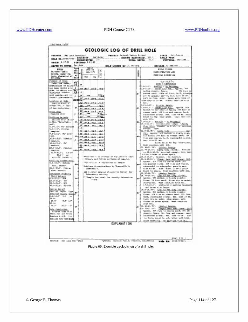
www.PDHcenter.com PDH Course C278 www.PDHonline.org
Figure 66. Example geologic log of a drill hole.
© George E. Thomas Page 114 of 127
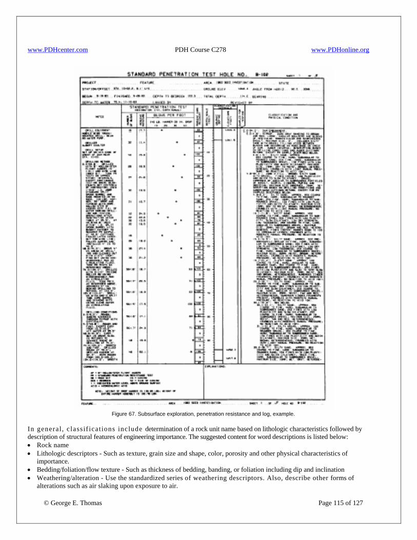
www.PDHcenter.com PDH Course C278 www.PDHonline.org
Figure 67. Subsurface exploration, penetration resistance and log, example.
In general , c lass if icat ions include determination of a rock unit name based on lithologic characteristics followed by description of structural features of engineering importance. The suggested content for word descriptions is listed below: • Rock name • Lithologic descriptors - Such as texture, grain size and shape, color, porosity and other physical characteristics of
importance. • Bedding/foliation/flow texture - Such as thickness of bedding, banding, or foliation including dip and inclination
© George E. Thomas Page 115 of 127
• Weathering/alteration - Use the standardized series of weathering descriptors. Also, describe other forms of alterations such as air slaking upon exposure to air.

www.PDHcenter.com PDH Course C278 www.PDHonline.org
• Hardness - Use standardized descriptors. • Discontinuities - Describe shears, fractures, and contacts.
− Note attitude, spacing, and roughness of bedding, foliation, and fractures. − Use standardized fracture density descriptors and characterize fracture frequency and Rock Quality Designation (RQD). − Describe shears and shear zones in detail, including all matrix materials present such as reworked material in the shear
zone. • Specific information for design. The empirical ground support (Q and RMR) calculations and the erodibility index utilize
specialized parameters.-The need for these parameters should be determined at the start of explorations. The recommended format for word descriptions (on boring logs) is one of the main headings describing lithologic groups, followed by indented subheadings and text describing important features of the core. Examples of classifications and physical descriptions for rock logging are shown in figure 66.
2. Log of Test Pit or Auger Hole. As shown in figure 68, Form 7-1336-A is used for logging test pits, auger holes, and other excavations, such as road cuts, through surficial soils. Predominant use of this form is for construction materials investigations and investigations for line structures such as pipelines and canals. This form is suitable for all types of exploratory holes which produce complete but disturbed samples. It can be used for logging auger holes where disturbed sampling is performed. Other exploratory drill holes advanced by rotary drilling methods are reported on drill hole logs discussed in the previous subsection. Detailed guidelines for logging test pits and auger holes are available through USBR to provide consistency in data presentation. Investigations of soils for construction require classification and description in accordance with the USCS. The log form (fig. 68) has a heading area at the top and a remarks area at the bottom. The body of the log form is divided into a series of columns to include the various kinds of information required. Columns are for: classification group symbol; classification and description of material; and the percentage of particles larger than 3” by volume. Information under the heading is required. Spaces are provided for supplying information such as project, feature, hole number, location, elevation, dates started and completed, and the name of the person responsible. Depths to bedrock and to water table (free water) are important information and should always be reported. The date when water level was measured is very important information, as water levels can change seasonally. When this or any other information called for on the log cannot be obtained, the reasons must be stated on the log or on other supporting documents. In the column for classification and group symbol, information such as group symbol, depth intervals logged, and samples taken are recorded. The system allows for modification of the group symbol with either prefixes or suffixes to further describe the soil . An example is shown on figure 68. The group symbol GW (well graded gravel) is modified by suffixes scb which indicate that sand, cobbles, and boulders are present to a significant extent in the sample. The typical name for the strata is WELL GRADED GRAVEL WITH SAND, COBBLES, and BOULDERS. While this system of abbreviations is useful for geologic drawings of borrow areas and trenches, considerable additional information is contained in the word descriptions, and decisions should not be based on group symbols alone.
© George E. Thomas Page 116 of 127
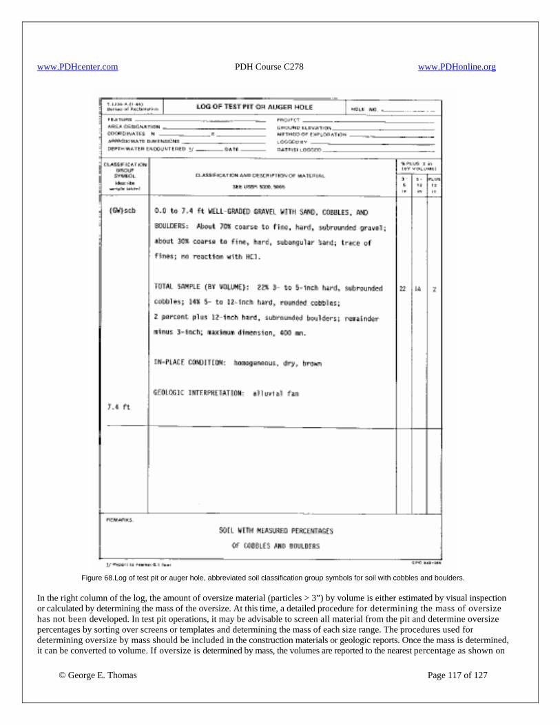
www.PDHcenter.com PDH Course C278 www.PDHonline.org
Figure 68.Log of test pit or auger hole, abbreviated soil classification group symbols for soil with cobbles and boulders.
© George E. Thomas Page 117 of 127
In the right column of the log, the amount of oversize material (particles > 3”) by volume is either estimated by visual inspection or calculated by determining the mass of the oversize. At this time, a detailed procedure for determining the mass of oversize has not been developed. In test pit operations, it may be advisable to screen all material from the pit and determine oversize percentages by sorting over screens or templates and determining the mass of each size range. The procedures used for determining oversize by mass should be included in the construction materials or geologic reports. Once the mass is determined, it can be converted to volume. If oversize is determined by mass, the volumes are reported to the nearest percentage as shown on

www.PDHcenter.com PDH Course C278 www.PDHonline.org
figure 68. If the volume of oversize is estimated visually, report percentages to the nearest 5 percent. If oversize is present, their presence is included in the log by adding to the typical name, and the particles are described as shown on the example of figure 68. The "Remarks" section of the log is for comments on the overall excavation or drilling. Information includes: • reason for stopping, • details on equipment used, • details on instrumentation, • legend for abbreviations, and • any miscellaneous comments. Terminating statements similar to the following would be considered satisfactory: • hole eliminated due to lack of funds, • hole caved in (include depth to cave), • depth limited by capacity of equipment, • hole terminated at predetermined depth, • encountered water, and • unable to penetrate hard material in bottom of hole. Material should not be described as bedrock, slide material, or similar interpretive terminology unless the exploration actually penetrated such conditions, and samples were collected to substantiate these conclusions. If rock is exposed at the base of a test pit, it can be logged. The classification and description portion of the log can vary depending on the type of excavation, type of testing performed, and the materials encountered. For disturbed soils, such as materials from power auger holes or stockpiles, all the information is in a paragraph as follows: • depth of strata, • USCS classification group name, • percentages and descriptions of the size fractions present (gravel, sand, and fines), • maximum particle size, • moisture, color, and odor, remarks, and • reaction with dilute solution HCl acid. If oversize is present in the logged strata, the next paragraph of word descriptions consists of describing the total sample by volume. The estimated percentages are given-along with a description of the cobbles and boulders-and the maximum size present. Noting the presence of oversize on test pit logs is extremely important. If only a trace or more of oversize is present, it must be included in the typical name. If the percentage of oversize (by volume) is less than 50 percent of the total volume, the characteristics of the oversize are described in a separate paragraph following description of the minus 75-mm (3-in) fraction. If the percentage of cobbles and/or boulders, by volume, exceeds 50 percent of the total material, the characteristics of the oversize are described in the first paragraph; the term cobbles and/or boulders is predominant in the typical name, and no classification symbol is assigned. An additional paragraph is added to the word descriptions if access is available to evaluate the in-place condition of the soil in an undisturbed state. In this case, reporting of moisture, color, and odor is omitted from the first paragraph and replaced with a more detailed description in a following paragraph. In this additional paragraph, information includes the following items in order of presentation. • consistency (fine grained soils only) - very soft, soft, firm, hard, and very hard • structure - homogeneous, stratified, blocky, fissured, laminated, etc. • cementation (coarse-grained soils only) • moisture, color, and odor • remarks
© George E. Thomas Page 118 of 127
An additional example of in-place condition descriptions is given on figure 69.
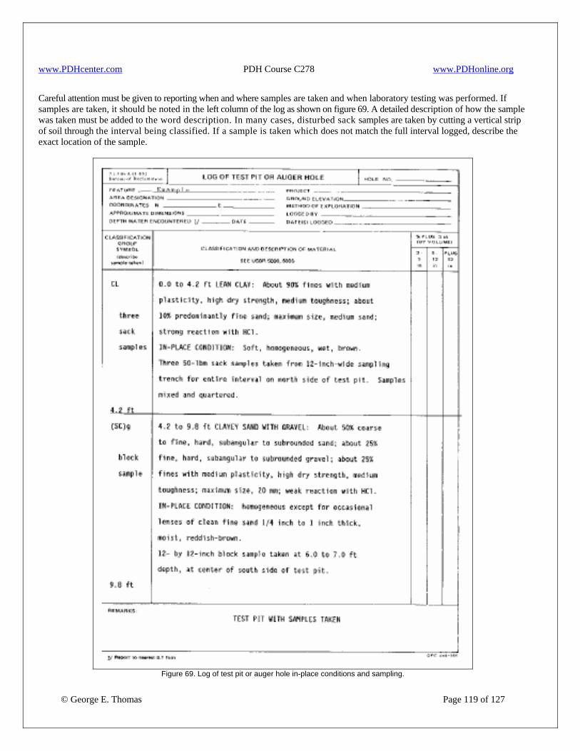
www.PDHcenter.com PDH Course C278 www.PDHonline.org
Careful attention must be given to reporting when and where samples are taken and when laboratory testing was performed. If samples are taken, it should be noted in the left column of the log as shown on figure 69. A detailed description of how the sample was taken must be added to the word description. In many cases, disturbed sack samples are taken by cutting a vertical strip of soil through the interval being classified. If a sample is taken which does not match the full interval logged, describe the exact location of the sample.
© George E. Thomas Page 119 of 127
Figure 69. Log of test pit or auger hole in-place conditions and sampling.

www.PDHcenter.com PDH Course C278 www.PDHonline.org
In cases where laboratory testing is performed for classifying the soil, this information must be as shown on the test pit logs. The ability for a classification to identify and describe soils is learned under the guidance of experienced personnel and by systematically comparing laboratory test results with visual classifications. On new projects, laboratory tests are sometimes used to "calibrate" the visual classifier when working with unfamiliar soils. However, visual classification is based upon total material observed and that laboratory classifications must be performed on representative materials for comparison with the visual information. In many cases, borrow area investigations will have a certain proportion of laboratory classifications to visual classification as verification. However, on large projects, it is not economical for all the classifications to be based solely upon results of laboratory testing. When the soil classification is based upon laboratory data, this must be clearly stated and distinctly noted on the log. Particle-size percentages are reported to the nearest 1 percent, and information on Atterberg limits, coefficients of uniformity and curvature are reported on the test pit log. Under the left column group symbol, the group symbols are noted as being obtained through laboratory classification. If laboratory classification tests are performed, and results of visual classification are also reported on the log, laboratory data are presented in a separate paragraph. Figure 70 llustrates combined reporting of visual and laboratory classifications. If the laboratory classification differs from the v isual classification, both group symbols are shown in the left column. Do not change the visual classification or description, based upon laboratory data, because the visual description is based upon a widely observed area. If the typical name is different, this is shown in the laboratory test data paragraph. In-place density tests are often performed in test pits and trenches in borrow areas to determine shrink-swell factors. In-place density tests are also performed in pipeline investigations to evaluate soil support for flexible pipe. In most cases, laboratory compaction tests are performed depending on the material and requirements of the investigation. The compaction tests are used to determined relative density or percent compaction. The in-place density and percent compaction or relative density must be reported in the paragraph on in-place condition on the log. In-place density tests such as the sand cone or nuclear gage normally represent a smaller interval than the interval logged. For in-place density tests, the interval is measured or estimated and reported on the log. On some features, using standard USCS group symbols and typical names may make it difficult to distinguish materials important to construction. For example, topsoil is normally stripped and stockpiled in construction operations. In this case, the log should clearly show the interpreted strata thickness and heading for topsoil present. An example follows: Classification symbol Description TOPSOIL 0.0 to 2.6 ft TOPSOIL would be classified as ORGANIC SOIL
(OL/OH). About 90% fines with low plasticity, slow dilatency, low dry strength, and low toughness; about 10% fine to medium sand; soft, wet, dark brown, organic odor, roots present throughout strata, weak reaction with HCl.
Other material types that may be important to distinguish for design and construction operations may be drill pad, gravel road surfacing, mine tailings, and fill or uncompacted fill. If a certain soil feature requires a special description for investigations, they should be determined at the beginning of the exploration program. The exploration team should consider these requirements and advise investigators of the special cases.
© George E. Thomas Page 120 of 127
The USCS was developed to classify naturally occurring soils; it was not intended for classifying lithified or manmade materials. Problems can occur by classifying a partially lithified material such as a weathered rock or shale as a soil. An example would be the use of power-auger holes in shales. If the power auger grinds up the shale into a soil-like material, problems could arise when excavating during construction. It is important to note that the visual classification was performed on materials after processing. Other materials such as claystones, processed aggregates, and natural materials (e.g., shells) are examples of materials where the group symbol and typical name from USCS should not be used without careful notation. Examples of logs for
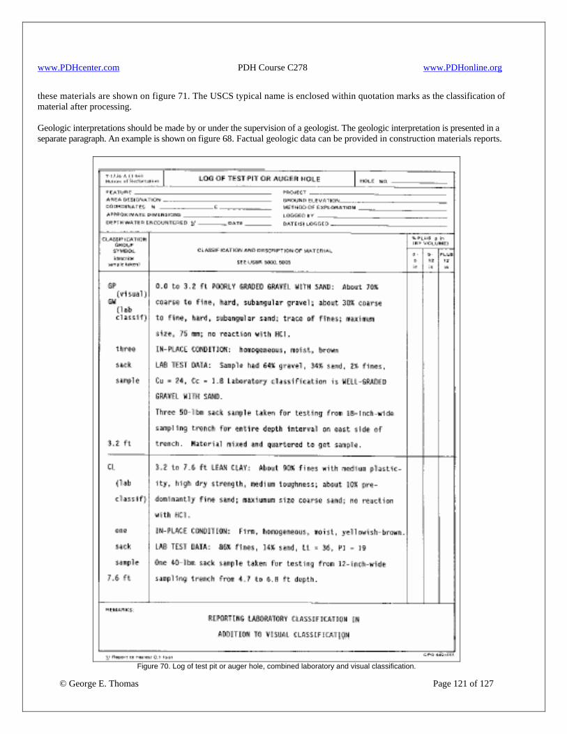
www.PDHcenter.com PDH Course C278 www.PDHonline.org
these materials are shown on figure 71. The USCS typical name is enclosed within quotation marks as the classification of material after processing. Geologic interpretations should be made by or under the supervision of a geologist. The geologic interpretation is presented in a separate paragraph. An example is shown on figure 68. Factual geologic data can be provided in construction materials reports.
© George E. Thomas Page 121 of 127
Figure 70. Log of test pit or auger hole, combined laboratory and visual classification.
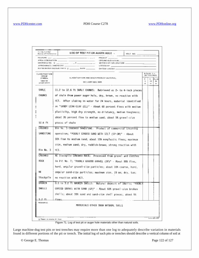
www.PDHcenter.com PDH Course C278 www.PDHonline.org
Figure 71. Log of test pit or auger hole materials other than natural soils.
© George E. Thomas Page 122 of 127
Large machine-dug test pits or test trenches may require more than one log to adequately describe variation in materials found in different portions of the pit or trench. The initial log of such pits or trenches should describe a vertical column of soil at
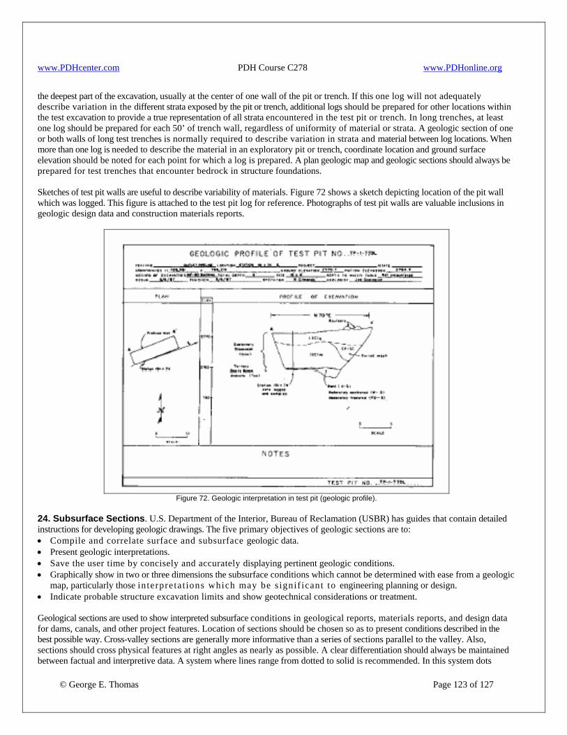
www.PDHcenter.com PDH Course C278 www.PDHonline.org
the deepest part of the excavation, usually at the center of one wall of the pit or trench. If this one log will not adequately describe variation in the different strata exposed by the pit or trench, additional logs should be prepared for other locations within the test excavation to provide a true representation of all strata encountered in the test pit or trench. In long trenches, at least one log should be prepared for each 50’ of trench wall, regardless of uniformity of material or strata. A geologic section of one or both walls of long test trenches is normally required to describe variation in strata and material between log locations. When more than one log is needed to describe the material in an exploratory pit or trench, coordinate location and ground surface elevation should be noted for each point for which a log is prepared. A plan geologic map and geologic sections should always be prepared for test trenches that encounter bedrock in structure foundations. Sketches of test pit walls are useful to describe variability of materials. Figure 72 shows a sketch depicting location of the pit wall which was logged. This figure is attached to the test pit log for reference. Photographs of test pit walls are valuable inclusions in geologic design data and construction materials reports.
Figure 72. Geologic interpretation in test pit (geologic profile).
24. Subsurface Sections. U.S. Department of the Interior, Bureau of Reclamation (USBR) has guides that contain detailed instructions for developing geologic drawings. The five primary objectives of geologic sections are to: • Compile and correlate surface and subsurface geologic data. • Present geologic interpretations. • Save the user time by concisely and accurately displaying pertinent geologic conditions. • Graphically show in two or three dimensions the subsurface conditions which cannot be determined with ease from a geologic
map, particularly those in terpretat ions which may be s ignif icant to engineering planning or design. • Indicate probable structure excavation limits and show geotechnical considerations or treatment.
© George E. Thomas Page 123 of 127
Geological sections are used to show interpreted subsurface conditions in geological reports, materials reports, and design data for dams, canals, and other project features. Location of sections should be chosen so as to present conditions described in the best possible way. Cross-valley sections are generally more informative than a series of sections parallel to the valley. Also, sections should cross physical features at right angles as nearly as possible. A clear differentiation should always be maintained between factual and interpretive data. A system where lines range from dotted to solid is recommended. In this system dots
www.PDHcenter.com PDH Course C278 www.PDHonline.org
represent purely hypothetical interpretation, a solid line represents fact, and dashed lines define the degree of reliability of intermediate data according to length of dash. The cross section should always show the name of the person who made the interpretation and the date the interpretation was made. 25. Sampling. Samples of soil and of rock are collected for visual examination so that a log of the test hole may be prepared for preservation as representative samples in support of the descriptive log, for testing to determine index properties, and for laboratory testing to determine engineering properties. When drilling core holes, the total material recovered as core is collected and stored in core resealable boxes. In addition, samples of soil should be collected and placed in sealed pint jars or resealable plastic bags to preserve the natural water content representative of each moist or wet stratum. Samples representative of the various types of material found in the area under investigation should be collected as the work progresses. Samples should be 4” to 6” long and must be representative of that material found in the area, particularly as to the degree of alteration. If a wide variation in material quality exists, samples representative of the ranges of the material should be collected. When exploring for materials in borrow areas and in foundations where substantial quantities occur that potentially may be used in embankment construction, samples should be collected representative of each stratum in a volume sufficient to provide 75 lb of material passing a No. 4 sieve to be used for testing for engineering properties. Only material larger than 3”should be removed from a sample, and the percentage of plus 3” removed should be reported. However, in some cases, larger samples are required for tests on total material. If the entire test hole appears to be in uniform material, samples from the upper, middle, and lower one-third of the test hole should be collected. When investigating riprap sources, samples consisting of three or four pieces of rock totaling at least 600 lb representative of the source should be collected. Collecting samples of blanketing material, filter material, and ballast should conform to requirements for collection of borrow material for embankment construction. From the set(s) of samples collected described above, samples are selected for performing index and engineering properties tests. Care should be taken to preserve sufficient samples to substantiate logs of exploratory holes and for representative samples to be transmitted. Samples collected in the process of routine exploration generally are not satisfactory for testing associated with determining properties of in-place soil or rock. For this purpose, samples of material unaffected by seasonal climatic influence are collected from large-diameter boreholes 4” to 6” in diameter minimum] or from the bottom of open pits. Borehole samples should be 12” to 24” long, and open-pit samples 10” to 18 cubes. Every effort should be made to preserve such samples in as nearly an in-place natural condition as possible. 26. Reports. a. General. Guidelines for preparing geologic design data reports are presented in the Engineering Geology Office Manual [69]. This guide contains detailed instructions concerning required information for inclusion in geologic design data reports. The results of every investigation should be presented in a report. In the reconnaissance stage for a small structure, a letter report describing in general terms the nature of problems associated with the investigation, the extent of the investigation, and the conclusions reached may suffice. As an investigation proceeds, additional data are collected and evaluated. As the various stages of investigation proceed, previously assembled material is incorporated in a progress report. During preparation of this progress report, previous reports should be examined; those questions which have been answered should be noted in the report together with the resolution or, if unanswered, should be carried over for future consideration. The final report should either answer all questions raised in the past or discuss why a positive solution cannot be reached within the scope of an investigation. Every investigation should contain: • A statement of the purpose of the investigation • The stage for which the report is being prepared • The kind of structure contemplated or the type of study • The principal dimensions of the structure
© George E. Thomas Page 124 of 127

www.PDHcenter.com PDH Course C278 www.PDHonline.org
The following features pertaining to foundations and earthwork should be included in all reports. b. Foundations and Earthwork. Foundation data should reflect recognition and consideration of the type and size of the particular engineering structure and the effect on, or relationship to, the structure of the significant characteristics of foundation materials and conditions at the particular site. The general regional geology should be described. The description should include major geological features, names of formations found in the area, their age, their relationship to one another, their general physical characteristics, and seismicity. • A description and interpretation of local geology should include:
− physical quality and geologic structure of foundation strata, − groundwater and seismic conditions, − existing and potential slide areas, and − engineering geologic interpretations appropriate to the engineering structure involved.
• Geologic logs of all subsurface explorations should be included in the report. • Combine geologic map plotted on the topographic map of the site showing surface geology and the location of geologic
sections and explorations. • Supplement the above map by geologic sections showing known and interpreted geologic conditions related to engineering
structures. • Photograph pertinent geologic and topographic features of the terrain, including aerial photographs for mosaics, if
available, are valuable additions to the report. Engineering data on overburden soils within the foundation of the proposed structure should be shown by detailed soil profiles and reported as follows: • A classification of the soil in each major stratum according to the Unified Soil Classification System. • A description of the undisturbed state of the soil in each stratum. • A delineation of the lateral extent and thickness of critical, competent, poor, or potentially unstable strata. • An estimate, or a determination by tests, of the significant engineering properties of the strata such as densi ty ,
permeabi l i ty , shear s t rength, and compressibility or expansion characteristics; and the effect of structure load, changes in water content, and fluctuations or permanent rise of ground water on these properties.
• An estimate or a determination of the corrosive properties and sulphate content of the soil and ground water as affecting the choice of cement for use in structures.
For data on bedrock, the following are required: • A description of the depth to and contour of bedrock, thickness of weathered, altered, or otherwise softened zones, and other
structural weaknesses and discontinuities. • A delineation of structurally weak, pervious, and potentially unstable zones and strata of soft rock and/or soil. • An estimate or a determination of the significant engineering properties of bedrock such as density, absorption, permeability,
shear strength, stress, and strain characteristics; and the effect of structure load, changes in water content, and fluctuations or permanent rise of groundwater on these properties.
c. Construction Materials Data. As part of the design data for earth dams, an earth materials report is required containing a list of: • available impermeable soils, • permeable soils, • sand for filters, and • rock for riprap and rockfill. Occasionally, a list is required for canals and other large structures when appreciable quantities of these materials are required. Sometimes, similar reports for smaller quantities of special materials are needed. The principal items to be covered in the earth materials report are: • A grid map showing the topography of the deposit and of the structure site and the intervening terrain if within a radius of 2
mi. The location of test holes and trenches should be shown using standard symbols. • Ownership of deposit.
© George E. Thomas Page 125 of 127
• Brief description of topography and vegetation.

www.PDHcenter.com PDH Course C278 www.PDHonline.org
• Estimated thickness of the deposit, including variations. Drawings showing subsurface profiles along grid lines should be included.
• Areal extent of the deposit. • Estimated quantity of the deposit. • Type and thickness of overburden. • Depth to water. • Accessibility to the source. • General description of rock. • Amount of jointing and thickness of bedding of rock strata. • Spacing, shape, angularity, average size, and range of sizes of natural boulder deposits. • Brief description of shape and angularity of rock fragments found on slopes and of the manner and sizes into which the
rock breaks when blasted. • Logs of all auger test holes and exposed faces of test trenches or pits. An estimate, or determination by tests, of the pertinent index and engineering properties of soils encountered. The amount of testing should be limited in the feasibility stage but should be more detailed for specifications. • Photographs, maps, and other drawings are helpful and desirable for the record of explorations. In most cases, information gathered for the earth materials report of an earth dam, for final design and specifications, may not be of sufficient detail to permit development of a p lan fo r us ing ava i l ab le ea r th ma te r i a l s to the best advantage. However, explorations should be sufficient to assure that sufficient materials required are available. As soon as funds are available for constructing the dam, additional studies can be performed. The primary purposes of a detailed study are to determine the depth of borrow pit cuts, the most efficient distribution of materials to be placed in the embankment, and the need for addition or removal of moisture. In most cases, it is desirable to add moisture to dry, impervious borrow materials before excavating. Studies should include an analysis of moisture conditions in each borrow area from which plans may be developed for irrigating the areas. If materials in borrow areas are too wet for proper placement, plans for draining these areas may be based upon results of detailed studies. Seasonal variations of water content, variation of water content with depth, and rate of water penetration are items requiring consideration. Detailed investigations are also desirable for canals and structures where large quantities of required excavations and borrow are involved. In any case, sufficient preconstruction explorations should be made to know where specified types of materials are to be obtained and where all materials are to be placed. Information on concrete aggregates should be reported. Information on sources and character of acceptable road surfacing materials, if required, should be given in the construction materials report. Reference should be made to results of sampling and analysis of materials, including previous tests. Figures 73 and 74 are example forms for summarizing field and laboratory tests on embankment materials which accompany preconstruction reports. Test procedures outlined in this course can be obtained for the U.S. Department of the Interior, Bureau of Reclamation (USBR).
© George E. Thomas Page 126 of 127

www.PDHcenter.com PDH Course C278 www.PDHonline.org
Figure 73. Summary of field and laboratory tests for embankment materials report, impermeable-type materials.
Figure 74. Summary of field and laboratory tests for embankment materials report,
permeable-type materials.
© George E. Thomas Page 127 of 127
Related Documents