18-AC71 D1-1 :!l!i i i Condensing 4"FrR3 n ALL phases of this installation must comply with NATIONAL, STATE AND LOCAL CODES IMPORTANT -- This Document is customer property and is to remain with this unit. Please return to service information pack upon completion of work. These instructions do not cover all variations in systems nor provide for every possible contingency to be met in connection with installation. All phases of this installation must comply with NATIONAL, STATE AND LOCAL CODES. Should further information be desired or should particular problems arise which are not covered sufficiently for the purchaser's purposes, the matter should be referred to your installing dealer or local distributor. A. GENERAL This information is intended for use by individuals posses- sing adequate backgrounds of electrical and mechanical experience. Any attempt to repair a central air conditioning product may result in personal injury and or property damage. The manufacturer or seller cannot be responsible for the interpretation of this information, nor can it assume any liability in connection with its use. NOTICE: Trane has always recommended installing Trane approved matched indoor and outdoor systems. The benefits of installing approved matched systems are maximum efficiency, optimum performance and best overall system reliability. These units use R-410A refrigerant which operates at 50 to 70% higher pressures than R-22. Use only R-410A approved service equipment. Refrigerant cylinders are painted a "Rose" color to indicate the type of refrigerant and may contain a "dip" tube to allow for charging of liquid refriger- ant into the system. All R-410A systems use a POE oil that readily absorbs moisture from the atmosphere. To limit this "hygroscopic" action, the system should remain sealed whenever possible, if a system has been open to the atmo- sphere for more than 4 hours, the compressor oil must be replaced. Never break a vacuum with air and always change the driers when opening the system for component replacement. For specific handling concerns with R-410A and POE oil, reference Retrofit Bulletin TRN-APGO2-EN. Check for transportation damage after unit is uncrated. Report promptly, to the carrier, any damage found to the unit. To determine the electrical power requirements of the unit, refer to the nameplate of the unit. The electrical power available must agree with that listed on the nameplate. UNiT CONTAINS R-410A REFRIGERANT! R-410A OPERATING PRESSURE EXCEEDS THE LIMIT OF R-22. PROPER SERVICE EQUIPMENT IS REQUIRED. FAILURE TO USE PROPER SERVICE TOOLS MAY RESULT IN EQUIPMENT DAMAGE OR PERSONAL INJURY. SERVICE USE ONLY R-410A REFRIGERANT AND APPROVED POE COMPRESSOR OIL. 5 FT. ABOVE UNiT -- UNRESTRICTED B. LOCATION AND PREPARATION OF THE UNiT 1. When removing unit from the pallet, notice the tabs on the basepan. Remove tabs by cutting with a sharp tool as shown in Figure 2 (see page 2). 2. The unit should be set on a level support pad at least as large as the unit base pan, such as a concrete slab. If this is not the application used please refer to application bulletin "Trane APB2001-02". 3, The support pad must NOT be in direct contact with any structure. Unit must be positioned a minimum of 12" from any wall or surrounding shrubbery to insure

Welcome message from author
This document is posted to help you gain knowledge. Please leave a comment to let me know what you think about it! Share it to your friends and learn new things together.
Transcript
18-AC71 D1-1
:!l!ii i
Condensing4"FrR3
n
ALL phases of this installation must comply with NATIONAL, STATE AND LOCAL CODES
IMPORTANT -- This Document is customer property and is to remain with this unit. Please return to service informationpack upon completion of work.
These instructions do not cover all variations insystems nor provide for every possible contingency tobe met in connection with installation. All phases ofthis installation must comply with NATIONAL, STATEAND LOCAL CODES. Should further information bedesired or should particular problems arise which are notcovered sufficiently for the purchaser's purposes, the mattershould be referred to your installing dealer or local distributor.
A. GENERAL
This information is intended for use by individuals posses-sing adequate backgrounds of electrical and mechanicalexperience. Any attempt to repair a central air conditioningproduct may result in personal injury and or propertydamage. The manufacturer or seller cannot be responsiblefor the interpretation of this information, nor can it assumeany liability in connection with its use.
NOTICE:Trane has always recommended installing Trane approvedmatched indoor and outdoor systems.
The benefits of installing approved matched systems aremaximum efficiency, optimum performance and bestoverall system reliability.
These units use R-410A refrigerant which operates at 50 to70% higher pressures than R-22. Use only R-410A approvedservice equipment. Refrigerant cylinders are painted a"Rose" color to indicate the type of refrigerant and maycontain a "dip" tube to allow for charging of liquid refriger-ant into the system. All R-410A systems use a POE oil thatreadily absorbs moisture from the atmosphere. To limit this"hygroscopic" action, the system should remain sealedwhenever possible, if a system has been open to the atmo-sphere for more than 4 hours, the compressor oil must bereplaced. Never break a vacuum with air and alwayschange the driers when opening the system for componentreplacement. For specific handling concerns with R-410Aand POE oil, reference Retrofit Bulletin TRN-APGO2-EN.
Check for transportation damage after unit is uncrated.Report promptly, to the carrier, any damage found to the unit.
To determine the electrical power requirements of the unit,refer to the nameplate of the unit. The electrical poweravailable must agree with that listed on the nameplate.
UNiT CONTAINS R-410A REFRIGERANT!R-410A OPERATING PRESSURE EXCEEDS THE
LIMIT OF R-22. PROPER SERVICE EQUIPMENT IS
REQUIRED. FAILURE TO USE PROPER SERVICE
TOOLS MAY RESULT IN EQUIPMENT DAMAGE OR
PERSONAL INJURY.
SERVICEUSE ONLY R-410A REFRIGERANT ANDAPPROVED POE COMPRESSOR OIL.
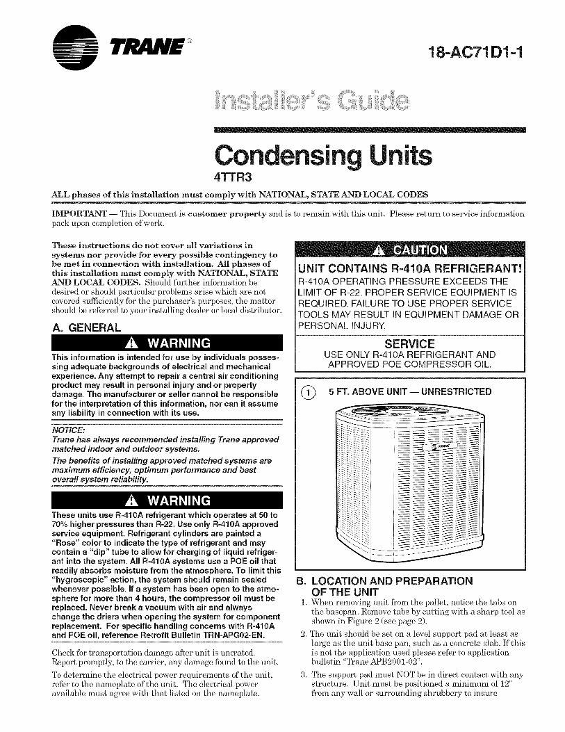
5 FT. ABOVE UNiT -- UNRESTRICTED
B. LOCATION AND PREPARATIONOF THE UNiT
1. When removing unit from the pallet, notice the tabs onthe basepan. Remove tabs by cutting with a sharp tool asshown in Figure 2 (see page 2).
2. The unit should be set on a level support pad at least aslarge as the unit base pan, such as a concrete slab. If thisis not the application used please refer to applicationbulletin "Trane APB2001-02".
3, The support pad must NOT be in direct contact with anystructure. Unit must be positioned a minimum of 12"from any wall or surrounding shrubbery to insure

|nstaI|er's Guide
@ BASEPAN TAB REMOVAL
[sE"°VE BS AS IOWN)
adequate airflow. Clearance must be provided in front ofcontrol box (access panels) & any other side requiringservice access to meet National Electrical Code. Also,the unit location must be far enough away from anystructure to prevent excess roof run-off water frompouring directly on the unit. Do not locate unit(s) closeto bedroom(s).
4. The top discharge area must be unrestricted for at leastfive (5) feet above the unit.
5. When the outdoor unit is mounted on a roof! be sure theroof will support the unit's weight. Properly selectedisolation is recommended to prevent sound or vibrationtransmission to the building structure.
6. The maximum length of refrigerant lines from outdoor toindoor unit should NOT exceed sixty (60) feet.
7. If outdoor unit is mounted above the air handler, maxi-mum lift should not exceed sixty (60) fhet (suction line).If air handler is mounted above condensing unit, maxi-mum lift should not exceed sixty (60) feet (liquid line).
NOTE:
Refer to "Refrigerant Piping Software" Pub. No. 32-3312-0"(the position of the * denotes the latest revision number).
8. Locate and install indoor coil or air handler in accor-dance with instruction included with that unit.
2. Consider types of bends to be made and space limitations.
NOTE:
Large diameter tubing will be very difficult to rebend once ithas been shaped.
3,
4.
5.
6.
7.
8.
Determine the best starting point for routing the refriger-ant tubing -- INSIDE OR OUTSIDE THE STRUCTURE.
Provide a pull-thru hole of sufficient size to allow bothliquid and gas lines.
Be sure the tubing is of sufficient length.
Uncoil the tubing -- do not kink or dent.
Route the tubing making all required bends and properlysecure the tubing before making connections.
To prevent a noise within the building structure due tovibration transmission from the refrigerant lines, thefollowing precautions should be taken:
a. When the refrigerant lines have to be fastened to floorjoists or other framing in a structure, use isolationtype hangers.
b. Isolation hangers should also be used -when refriger-ant lines are run in stud spaces or enclosed ceilings.
c. Where the refrigerant lines run through a wall or sill,they should be insulated and isolated.
d. Isolate the lines from all ductwork.
D. SERVICE VALVE OPERATION
BRASS LIQUID AND GAS LINE SERVICE VALVESThe Brass Liquid and Gas Line Service Valves are factoryshipped in the seated position to hold factory charge. Thepressure tap service port (when depressed) opens only to thefield brazing side of the valve when the valve is in the seatedposition. The liquid line valve is not a back seating valve(see WARNING below).
C. iNSTALLiNG REFRIGERANT LINES
If using existing refrigerant lines make certain that all jointsare brazed, not soldered.
Extreme caution should be exercised when opening theLiquid Line Service Valve. Turn valve stem counterclock=wise only until the stem contacts the rolled edge. (SeeFigure 3.) No torque is required.
Condensing units have provisions for braze connections.
Pressure taps are provided on the service valves of outdoorunit for compressor suction and liquid pressures.
The indoor end of the recommended refrigerant line sets maybe straight or with a 90 degree bend, depending upon situa-tion requirements. This should be thoroughly checked outbefore ordering refrigerant line sets.
The gas line must always be insulated.
In scroll compressor applications, dome temperatures maybe hot. Do not touch top of compressor, may cause minorto severe burning.
The units are factory charged with the system charge requiredwhen using fiiteen (15) f_et of rated connecting line. Unitnameplate charge is with twenty-five (25) feet of line set.
Final refrigerant charge adjustment is necessary. Usethe Subcooling Charging procedure on page 6 or in theoutdoor unit Service Facts.
1. Determine the most practical way to run the lines.
BRASS GAS LINE BALL SERVICE VALVE
The Brass Gas Line Ball Service Valve is shipped in theclosed position to hold the factory refrigerant charge. Thepressure tap service port (when depressed) opens only to thefield brazing side when the valve is in the closed position.The Gas Line Ball Service Valve is full open with a 1/4 turn.See Figure 4.
BRAZING REFRIGERANT LINES1. Remove lower access cover to access service valves.
2,
3,
4.
5.
6.
Before brazing, remove plugs from external copper stubtubes. Clean internal and external surfaces of stub
tubes prior to brazing.
Cut and fit tubing, minimizing the use of sharp90 ° bends.
Insulate the entire gas line and its fittings.
Do NOT allow uninsulated liquid line to come in directcontact with bare gas line.
Precautions should be taken to avoid heat damageto the pressure tap valve core during brazing. It isrecommended that the pressure tap port valvecore be removed and a wet rag wrapped aroundthe valve body.
© 2006 American Standard inc. All Rights Reserved 18-AC71 D1-1

|nstaI|er's Guide
® LIQUID LINE SERVICE VALVE
ROLLED EDGE TO
CAP_ _ / CAPTIVATE STEM
SERVICE _ k_,V /
PORT -- /
LIQUID LINECONNECTION
NOTE:
Use care to make sure that no moisture enters pressure tapport, while wet rag is being used.
NOTE:
Precautions should be taken to avoid heat damage tobasepan during brazing. It is recommended to keep theflame directly off of the basepan.
7. Use a Dry Nitrogen Purge and Brazing Alloy withoutflux when brazing the field line to the copper factoryconnection. Flow dry nitrogen into either valve pressuretap port, thru the tubing and out the other port whilebrazing.
8. Braze using accepted good brazing techniques.
LEAK CHECK
IMPORTANT:
Replace pressure tap port valve core before attaching hoses forevacuation.
After the brazing operation of refrigerant lines to both theoutdoor and indoor units is completed, the field brazedconnections must be checked for leaks. Pressurize throughthe service valve ports, the indoor unit and field refrigerantlines with dry nitrogen to 350-400 psi. Use soap bubbles orother leak-checking methods to see that all field joints areleak-free! If not, release pressure; then repair!
SYSTEM EVACUATION
NOTE:
Since the outdoor unit has a refrigerant charge, the gas andliquid line valves must remain closed.
1. Upon completion of leak check, evacuate the refrigerantlines and indoor coil before opening the gas and liquidline valves.
2. Attach appropriate hoses from manifold gauge to gasand liquid line pressure taps.
NOTE:Unnecessary switching of hoses can be avoided andcomplete evacuation of all lines leading to sealed systemcan be accomplished with manifold center hose andconnecting branch hose to a cylinder of R-410A andvacuum pump.
3. Attach center hose of manifold gauges to vacuum pump.
4. Evacuate until the micron gauge reads no higher than350 mierons.
5. Close offvalve to vacuum pump and observe the mierongauge. If gauge pressure rises above 500 microns in one (1)minute, then evacuation is incomplete or system has a leak.
6. If vacuum gauge does not rise above 500 microns inone (1) minute, the evacuation should be complete.
7. Blank off vacuum pump and micron gauge, closevalves on manifold gauge set.
NOTE:DO NOT VENT REFRIGERANT INTO THE ATMOSPHERE.
NOTE:A 3/16"Allen wrench is required to open liquid line servicevalve. A 1/4" Open End or Adjustable wrench is required toopen gas line valve. A 3/4" Open End wrench is required totake off the valve stem cap.
8. The liquid line shut-off valve can now be opened. Removeshut-off valve cap. Fully insert hex wrench into the steinand backout counterclockwise until valve stein just touchesrolled edge (approximately five [5] turns) observingWARNING statement on page 2. See Figure 3.
9. Replace liquid service pressure tap port cap and valvestem cap. These caps MUST BE REPLACED toprevent leaks. Replace valve stem cap and pressure tapcap finger tight, then tighten an additional 1/6 turn.
10. The gas valve can now be opened. Open the gas valve byremoving the shut-off valve cap and turning the valvestein 1/4 turn counterclockwise, using 1/4" Open End orAdjustable wrench. See Figures 4 and 5.
11. The gas valve is now open for refrigerant flow. Replacevalve stem cap to prevent leaks. Again, these capsMUST BE REPLACED to prevent leaks. Replace valvestem cap and pressure tap cap finger tight, then tightenan additional 1/6 turn. See Figures 4 and 5.
If refrigerant lines are longer than fifteen (15) f_et and/ora different size than recommended, it will be necessaryto adjust system refrigerant charge upon completion ofinstallation. See page 6 or the unit Service Facts.
© GAS LINE BALL SERVICE VALVE
CAP _ J--| 1/4 TURN ONLY
COUNTERCLOCKWISEFOR FULL OPEN
UNIT SIDE
OF VALVE
VALVE STEM
PRESSURE TAPPORT /
GAS LINE CONNECTION
@ GAS LINE SERVICE VALVE
/ROLLED EDGE TO
CAPTIVATE STEM
CAP_
HEXHEADEDUNIT SIDE OF
SERVICE VALVE_ VALVE SYSTEM
SERVICE_
PORT /GAS LINE
CONNECTION
18-AC71 D1-1 3

|nsta||er's GuideE. ELECTRICAL CONNECTIONS
When installing or servicing this equipment, ALWAYSexercise basic safety precautions to avoid the possibility ofelectric shock.
1. Power wiring and grounding of equipment must complywith local codes.
2. Power supply must agree with equipment nameplate.
3. Install a separate disconnect switch at the outdoor unit.
4. Ground the outdoor unit per local code requirements.
5. Provide flexible electrical conduit whenever vibration
transmission may create a noise problem within thestructure.
6. The use of color coded low voltage wire is recommendedto simplify connections between the outdoor unit, thethermostat and the indoor unit.
Table 1 -- NEC Class II Control Wiring
24 VOLTS
WIRE SIZE MAX. WIRE LENGTH
18 AWG 150 FT
16 AWG 225 FT.
14 AWG 300 FT.
7. Table i defines maximum total length of low voltagewiring from outdoor unit, to indoor unit, and to thermostat.
8. Mount the indoor thermostat in accordance with instruc-tion included with the thermostat. Wire per appropriatehook-up diagram (included in these instructions).
F. COMPRESSOR START-UPAfter all electrical wiring is complete, SET THE THERMO-STAT SYSTEM SWITCH IN THE OFF POSITION SOCOMPRESSOR WILL NOT RUN, and apply power byclosing the system main disconnect switch. This will activatethe compressor sump heat (where used). Do not change theThermostat System Switch until power has been applied forone (1) hour. Following this procedure -will prevent potentialcompressor overload trip at the initial start-up.
G. OPERATIONAL ANDCHECKOUT PROCEDURES
Final phases of this installation are the unit Operational andCheckout Procedures which are found in this instruction (seetable below and pages 6 and 8). To obtain proper perfor-mance, all units must be operated and charge adjustmentsmade in accordance with procedures found on page 6 and inthe Service Facts.
iMPORTANT:Perform a final un# inspection to be sure that factory tubing hasnot shifted during shipment. Adjust tubing ff necessary so tubesdo not rub against each other when the unit runs. Also be surethat wiring connections are tight and wire routing is secure.
H. SEACOAST SHIELDUnits installed -within one (1) mile of salt water, includingseacoasts and inland waterways, require the addition ofBAYSEAC001 (Seacoast Kit) at the time of installation.
iMPORTANT:
See Limited Warranty information in Use and Care Manual
I. TROUBLESHOOTING
TROUBLESHOOTING CHART m WHAT TO CHECK
SYSTEMFAULTS
REFRIGERANTCIRCUIT
UquidPressureTooHigh P P S P S S S
UquidPressureTooLow S P S S S S
SuctionPressureTooHigh S P P S P
SuctionPressureTooLow S S P S
LiquidRefrig.FIoodbackTXVSystem S S
I.D.CoilFrosting P P S
CompressorRunsInadequateorNoCooling S P P S S P S
ELECTRICAL
Compressor&O.D.FanDoNotStart P P S P P P
CompressorNllNotStartButO.D.FanRuns P S P P P S
O.D.FanWon'tStart P P
CompressorHumsButWon'tStart P P P P S S
CompressorCyclesonlOL P S P P P S P S P S S S S S
I.D.BlowerWon'tStart P S S P P
P- Primary Causes S- SecondaryCauses
4 18-AC71 D1-1

|nstal|er's Guide
TYPICAL FIELD HOOK=UP DIAGRAMS
T'STAT IR HANDIER
...... R
...... Wl
AI COND TONER
...... y
ODT
......
VARIABLE SPEEDT'STA/ AIR HANDLER AIR CONDIIIONER
--------133
[!3
F21,
F53
Ob A
t:7'B
PRINTEDFROM B152901P02PRINTED FROMB}52908P03
CONNECTIONS TO BE MADE FOR OPERATION OFBLOWERWllH HUMIDISTA] IN COOLING
T 'SIAl
NOTE
I -STAGEOR
2-STAGEFURNACE
[3
A COND [lONER
_. ..... y
PRINTEDFROMB152g03P02
-kW2 present only on 2 stagethermostat and furnace
Notes:
1. Be sure power supply agrees with equipment nameplate.
2. Power wiring and grounding of equipment must comply with local codes.
3. Low voltage wiring to be No. 18 AWG minimum conductor.4. ODT-B must be set lower than ODT-A.
5. If outdoor thermostats (ODT) are not used, connect W1 to W2 and W3.
T 'STAVAR AB[I SPEIO
2 SIAGE FURNAC AI COND!]IONER
r._F_
i-tiTI
FI
-- []_______ _..._
E!I
NO1F []
I_ f"_
PR NTID FRO BIS290/P04
LEGEND
..... FACTORY WIRING
_ FIELD WIRING
18-AC71 D1-1 5

|nsta||er's GuideSUBCOOMNG CHARGING iN COOLING ABOVE 55°F OD AMBIENT
The Trane company has always recommended installing
Trane approved matched indoor and outdoor systems.
All Trane split systems are ARI rated with only TXV indoorsystems.
The benefits of installing approved indoor and outdoor splitsystems are maximum efficiency, optimum performance andthe best overall system reliability.
The following charging methods are thereforeprescribed for systems with indoor TXVs.
1. Subcooling (in the cooling mode) is therecommended method of charging above55°F ambient temperatures.
2. For best results - the indoor temperatureshould be kept between 70°F to 80°F. Addsystem heat if needed.
3. At start-up, or -whenever charge isremoved or added, the system must beoperated for a minimum twenty (20)minutes to stabilize before accuratemeasurements can be made.
4. Measure Liquid Line Temperature andRefrigerant Pressure at service valves.
5. Determine total refrigerant line length,and height (lift) if indoor section is abovethe condenser.
6. Determine the Design Subcool ChargingTemperature from the unit nameplate.
7. Locate this value in the appropriate col-umn of the Subcooling Charging Table.Locate your liquid line temperature in theleft column of the table, and theintersecting liquid line pressure underyour nameplate subcool value column. Addrefrigerant to raise the pressure to match
LIQUIDTEMP(°F)
the table, or remove refrigerant to lower the pressure.Again, -wait twenty (20) minutes for the systemconditions to stabilize before adjusting charge again.
8. When system is correctly charged, you can refer toSystem Pressure Curves (in Service Facts) to verifytypical performance.
R=410A REFRIGERANT CHARGING CHART
DESIGN SUBCOOLING (°F)
8 I 9 ! lo 111 ! 12113LIQUID GAGE PRESSURE (PSI)
I 14
55 179 182 185 188 191 195 19860 195 198 201 204 208 211 21565 211 215 218 222 225 229 23270 229 232 236 240 243 247 25175 247 251 255 259 263 267 27180 267 271 275 279 283 287 29185 287 291 296 300 304 309 31390 309 313 318 322 327 331 33695 331 336 341 346 351 355 360
100 355 360 365 370 376 381 386105 381 386 391 396 402 407 413110 407 413 418 424 429 435 441115 435 441 446 452 458 464 470120 464 470 476 482 488 495 501125 495 501 507 514 520 527 533
Referto Service Facts orInstaller's Guide for charging method.
From Dwg. D154557P01 Rev. 2
SUBCOOL CHARGING TABLE CORRECTIONS FOR LINE LENGTH AND RISE
ZLU<m
C5=J
LUrr-q
co i!i ii i
i°0,"5 Table Pressure
20
15 ................................lo l
0 Subtract 10 psig from S.C. Table Pressure
10 20 25 30 40 60 80
TOTAL REFRIGERANT LINE LENGTH (FEET)
6 18-AC71 D1-1

|nsta||er's Guide
4TTR3 OUTLINE DRAWINGNOTE: ALL DIMENSIONS ARE IN IVllVl(INCHES).
B
SERVICE PANE!-- ...................
E_ECTRICAL AND REFRIGERANTCOMPONENTCLEARANCESPER PREVAILING CODES
TOP DISC_IARGE AREA SHOULD BEUNRESIRIC_FD FOR AF LEASF 1524 (5 J:EF])
ABOVE UN}T UNIT SHOULD BE PLACED SO ROOFRUN OFF WA/ER DOES NOI POUR DJRECI[Y ON UNIT,AND SHOULD BE A/ lEAS] 305 {12") FROM WALIo AND
ALL SURROUNDING SHRUBBERY ON TWO SIDESOTItER TWO SIDES UNRESTRICTED
MODELS
4TTR3018A
4TTR3024A
4TTR3030A
4TTR3036A
4TTR3042A
4TTR3048A
4TTR3060A
BASE
3
3
3
3
4
4
4
K
ELECTR!CAL SERVICE__PANEL
22 2 (7/8) DIALOW VOLTAGE
28 6 (}1/8) DIA KO WITH _222 (7/8) DIA HOLE }N CONTROL
BOX BOttOM FOR ELFC[RICALPOWER SUPPLY
IolOUII5 lINE SERVICE VALVE"{" I D FEMALE BRAZECONNECTION WITH I/4" SAE HFLARE PRFSSURF TAP FITTINGS
FIG.
1
1
1
1
1
1
1
A B
832 (32-3/4) 829 (32-5/8)
832 (32-3/4) 829 (32-5/8)
832 (32-3/4) 829 (32-5/8)
933 (36-3/4) 829 (32-5/8)
841 (33-1/8) 946 (37-1/4)
841 (33-1/8) 946 (37-1/4)
1045 (41-1/8) 946 (37-1/4)
J
G
C
756 (29-3/4)
756 (29-3/4)
756 (29-3/4)
756 (29-3/4)
870 (34-1/4)
870 (34-1/4)
870 (34-1/4)
FOR ALTERNATE
\ ELECTRICAL ROUTING\\LGAS L}N[ J/4 TURN BALI SERVICE VAIVE, "D'_
}1) FEMALE: BRAZED CONNECT}ON W}IH I/4" SAEF{ARE PRESSURE TAP FITTING
D E F G H
1/2 1/4 143 (5-5/8) 92 (3-5/8) 210 (8-1/4)
5/8 5/16 143 (5-5/8) 92 (3-5/8) 210 (8-1/4)
3/4 5/16 143 (5-5/8) 92 (3-5/8) 210 (8-1/4)
3/4 3/8 143 (5-5/8) 92 (3-5/8) 210 (8-1/4)
3/4 3/8 152 (6) 98 (3-7/8) 219 (8-5/8)
7/8 3/8 152 (6) 98 (3-7/8) 219 (8-5/8)
7/8 3/8 152 (6) 98 (3-7/8) 219 (8-5/8)
J
79 (3-1/8)
79 (3-1/8)
79 (3-1/8)
79 (3-1/8)
86 (3-3/8)
86 (3-3/8)
86 (3-3/8)
K
508 (20)
508 (20)
508 (20)
508 (20)
508 (20)
508 (20)
508(20)
69rr
ooObooO4LO
d3E£14-
18-AC71 D1-1 7
|nsta||er's Guide
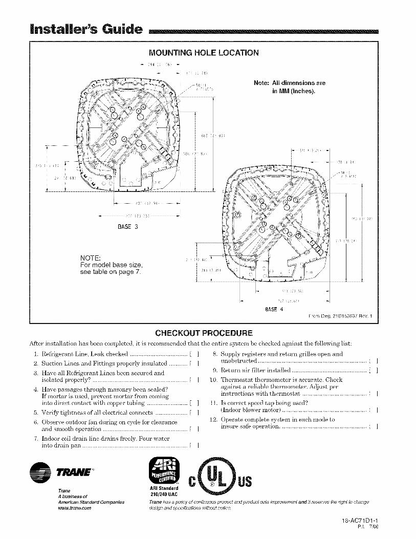
MOUNTING HOLE LOCATION
_29,1 ( 156)_
...................................482 { 8 99 ) ...............................
99 (21} 58)
BASE 3
NOTE:For model base size,see table on page 7.
i'4)
Note: All dimensions arein IVllVl(Inches).
2 ",2/3 64 )
BASE4
.........i58 (62_)
,'95 (3i28)
i ( ! 2/-
From Dwg. 21D152637 Rev. 1
CHECKOUT PROCEDURE
After installation has been completed, it is recommended that the entire system be checked against the following list:
1. Refrigerant Line, Leak checked .................................. [ ]
2. Suction Lines and Fittings properly insulated ........... [ ]
3. Have all Refrigerant Lines been secured andisolated properly? ........................................................ [
4. Have passages through masonry been sealed?If mortar is used, prevent mortar from cominginto direct contact with copper tubing ........................ [
5, Verify tightness of all electrical connects ................... [
6. Observe outdoor fan during on cycle for clearanceand smooth operation .................................................. [
7, Indoor coil drain line drains freely. Pour waterinto drain pan .............................................................. [
]
]
8, Supply registers and return grilles open andunobstructed ................................................................ [ ]
9. Return air filter installed ............................................ [ ]
10. Thermostat thermometer is accurate. Checkagainst a reliable thermometer. Adjust perinstructions with thermostat ...................................... [ ]
11. Is correct speed tap being used?(Indoor blower motor) .................................................. [ ]
12. Operate complete system in each mode toinsure safe operation ................................................... [ ]
Trane ARI StandardA business of 210/240 UAC
American Standard Companieswww.trane.com
C USTrane has a policy of continuous product and product data improvement and it reserves the right to change
design and specifications without notice.
18-AC71 D1-1P.I. 7/06
Related Documents