CONDENSING GAS WATER HEATER WHC56, LWHC56 (Internal) INSTALLATION AND SERVICE MANUAL Andrews. Built to perform. Please read and understand these instructions before commencing installation and leave this manual with the customer for future reference. Part number E890 SBA8198-3

Welcome message from author
This document is posted to help you gain knowledge. Please leave a comment to let me know what you think about it! Share it to your friends and learn new things together.
Transcript
CONDENSING GAS WATER HEATERWHC56, LWHC56 (Internal)
INSTALLATION AND SERVICE MANUAL
Andrews. Built to perform.
Please read and understand these instructions before commencing installation and leave this manual with the customer for future reference.
Part number E890
SBA8198-3

Potential dangers from accidents during installation and use are divided into the following threecategories. Closely observe these warnings, they are critical to your safety.
Prohibited DisconnectPower Earth Be sure to do
• Failures and damage caused by erroneous work or work not as instructed in this manual are notcovered by the warranty.
• Check that the installation was done properly in accordance with this Installation Manual uponcompletion.
• After completion of installation, be sure to hand the Operation Manual to the customer upon fillingin all of the required items.
Requests to Installers• In order to use the water heater safely, read this installation manual carefully,
and follow the installation instructions.Caution
WARNING: If the information in this manual is not followed exactly, a fire or explosion may resultcausing property damage, personal injury or death.
Warning
Caution
Danger Danger of serious injury or even death as well as danger of fire when theproduct is misused by ignoring this symbol.
Possibility of serious injury or even death as well as possibility of fire whenthe product is misused by ignoring this symbol.
Possibility of bodily injury or damage to property when the product ismisused by ignoring this symbol.
• The appliance must be installed in accordance with the Gas Safety (Installation and Use) Regulationsand the rules in force in the country of installation.
• The manufacturer's instructions supplied.• The Gas Safety (Installation and Use) Regulations.• The appropriate Buildings Regulations either The Building Regulations, The Building Regulations
(Scotland), The Building Regulations (Northern lreland).• In IE, the installation must be carried out by a competent person and installed in accordance with the
current edition of I.S.813 "Domestic Gas Installations", the current Building Regulations and referenceshould be made to the current ETCI rules for Electrical Installation.
SBA8198-3
Installation ManualCONDENSING GAS WATER HEATER
5, Minamifutami, Futami-cho,Akashi, Hyogo, Japan
NORITZ CORPORATIONPRODUCT :
AGENT :ANDREWS WATER HEATERS
WHC56, LWHC56 (Internal)
Innovation House 3 Oaklands Business Centre Oaklands Park Wokingham Berkshire RG41 2FD, UK
2
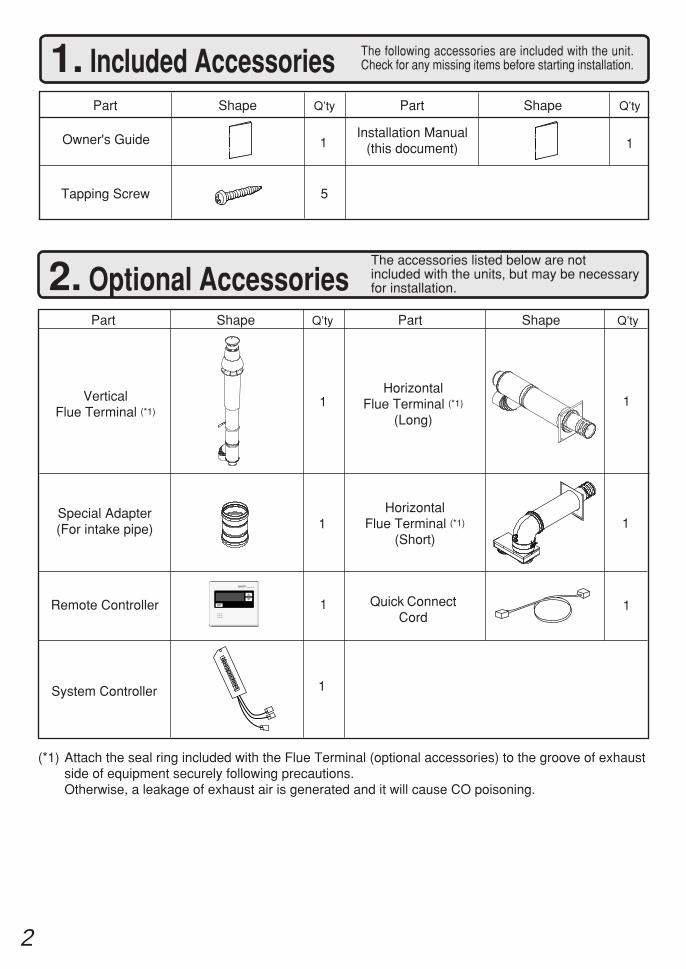
2. Optional AccessoriesThe accessories listed below are notincluded with the units, but may be necessaryfor installation.
Q’tyShapePartPart Shape Q’ty
Quick ConnectCord
1
1. Included Accessories The following accessories are included with the unit.Check for any missing items before starting installation.
Q’tyShapePart
Tapping Screw
1
Part Shape Q’ty
5
Installation Manual(this document)1Owner's Guide
System Controller 1
Remote Controller 1
HorizontalFlue Terminal (*1)
(Short)
HorizontalFlue Terminal (*1)
(Long)1Vertical
Flue Terminal (*1)1
1Special Adapter(For intake pipe) 1
(*1) Attach the seal ring included with the Flue Terminal (optional accessories) to the groove of exhaustside of equipment securely following precautions.Otherwise, a leakage of exhaust air is generated and it will cause CO poisoning.
3
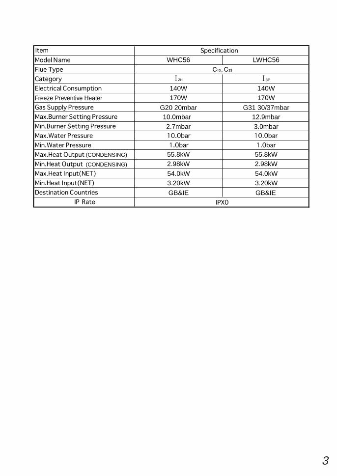
WHC56
140W
G20 20mbar
55.8kW
(CONDENSING)
(CONDENSING)
Freeze Preventive Heater
55.8kW2.98kW 2.98kW
54.0kW 54.0kW3.20kW 3.20kW
GB&IEGB&IE
G31 30/37mbar
140W170W 170W
LWHC56
3P
10.0mbar2.7mbar
12.9mbar3.0mbar
4
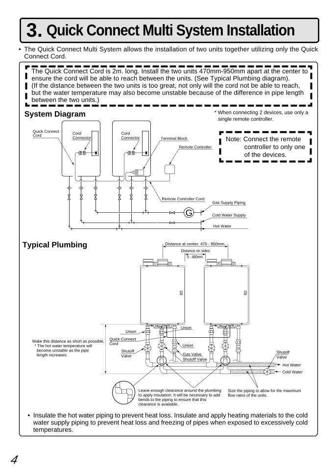
3. Quick Connect Multi System Installation• The Quick Connect Multi System allows the installation of two units together utilizing only the Quick
Connect Cord.
Typical Plumbing
The Quick Connect Cord is 2m. long. Install the two units 470mm-950mm apart at the center toensure the cord will be able to reach between the units. (See Typical Plumbing diagram).(If the distance between the two units is too great, not only will the cord not be able to reach,but the water temperature may also become unstable because of the difference in pipe lengthbetween the two units.)
* When connecting 2 devices, use only asingle remote controller.
Note: Connect the remotecontroller to only oneof the devices.
System Diagram
• Insulate the hot water piping to prevent heat loss. Insulate and apply heating materials to the coldwater supply piping to prevent heat loss and freezing of pipes when exposed to excessively coldtemperatures.
G
Quick Connect Cord
Remote Controller CordGas Supply Piping
Cold Water Supply
Hot Water
Remote Controller
Terminal BlockCord Connector
Cord Connector
Leave enough clearance around the plumbing to apply insulation. It will be necessary to add bends to the piping to ensure that this clearance is available.
Size the piping to allow for the maximum flow rates of the units.
Union
Distance at center: 470 - 950mm.
Quick ConnectCord
Union
ShutoffValve
Shutoff ValveHot Water
Shutoff Valve
Cold Water
Distance on sides
5 - 480mm.
Make this distance as short as possible. * The hot water temperature will become unstable as the pipe length increases.
Union
Gas Valve
5
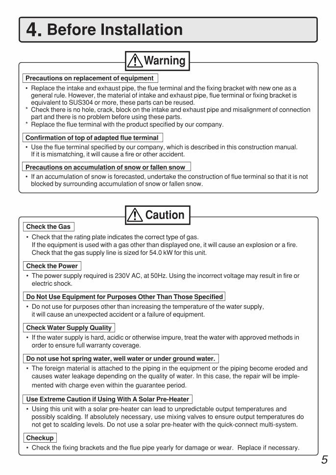
Check the Gas
• Check that the rating plate indicates the correct type of gas.If the equipment is used with a gas other than displayed one, it will cause an explosion or a fire.Check that the gas supply line is sized for 54.0 kW for this unit.
Check the Power
• The power supply required is 230V AC, at 50Hz. Using the incorrect voltage may result in fire orelectric shock.
Do Not Use Equipment for Purposes Other Than Those Specified
• Do not use for purposes other than increasing the temperature of the water supply,it will cause an unexpected accident or a failure of equipment.
Check Water Supply Quality• If the water supply is hard, acidic or otherwise impure, treat the water with approved methods in
order to ensure full warranty coverage.
Do not use hot spring water, well water or under ground water.• The foreign material is attached to the piping in the equipment or the piping become eroded and
causes water leakage depending on the quality of water. In this case, the repair will be imple-mented with charge even within the guarantee period.
Use Extreme Caution if Using With A Solar Pre-Heater• Using this unit with a solar pre-heater can lead to unpredictable output temperatures and possibly scalding. If absolutely necessary, use mixing valves to ensure output temperatures do
not get to scalding levels. Do not use a solar pre-heater with the quick-connect multi-system.
Checkup
• Check the fixing brackets and the flue pipe yearly for damage or wear. Replace if necessary.
4. Before Installation
Caution
Precautions on replacement of equipment
• Replace the intake and exhaust pipe, the flue terminal and the fixing bracket with new one as ageneral rule. However, the material of intake and exhaust pipe, flue terminal or fixing bracket isequivalent to SUS304 or more, these parts can be reused.
* Check there is no hole, crack, block on the intake and exhaust pipe and misalignment of connectionpart and there is no problem before using these parts.
* Replace the flue terminal with the product specified by our company.
Confirmation of top of adapted flue terminal• Use the flue terminal specified by our company, which is described in this construction manual.
If it is mismatching, it will cause a fire or other accident.
Precautions on accumulation of snow or fallen snow• If an accumulation of snow is forecasted, undertake the construction of flue terminal so that it is not
blocked by surrounding accumulation of snow or fallen snow.
Warning
6
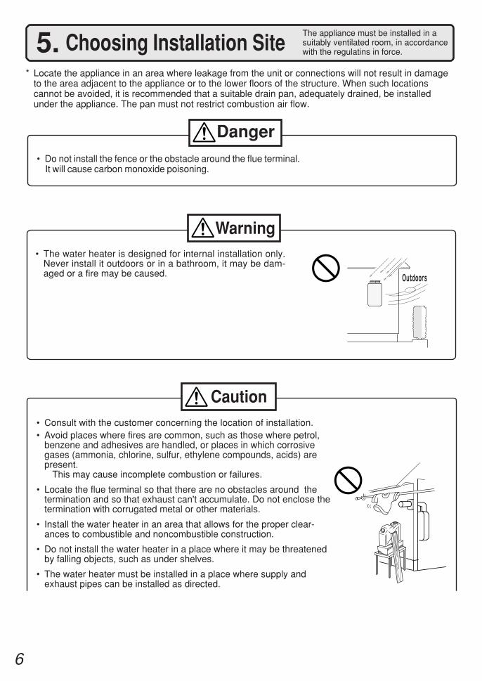
5. Choosing Installation Site* Locate the appliance in an area where leakage from the unit or connections will not result in damage
to the area adjacent to the appliance or to the lower floors of the structure. When such locationscannot be avoided, it is recommended that a suitable drain pan, adequately drained, be installedunder the appliance. The pan must not restrict combustion air flow.
The appliance must be installed in asuitably ventilated room, in accordancewith the regulatins in force.
• Do not install the fence or the obstacle around the flue terminal. It will cause carbon monoxide poisoning.
Danger
• The water heater is designed for internal installation only.Never install it outdoors or in a bathroom, it may be dam-aged or a fire may be caused.
Warning
Caution• Consult with the customer concerning the location of installation.• Avoid places where fires are common, such as those where petrol,
benzene and adhesives are handled, or places in which corrosivegases (ammonia, chlorine, sulfur, ethylene compounds, acids) arepresent. This may cause incomplete combustion or failures.
• Locate the flue terminal so that there are no obstacles around thetermination and so that exhaust can't accumulate. Do not enclose thetermination with corrugated metal or other materials.
• Install the water heater in an area that allows for the proper clear-ances to combustible and noncombustible construction.
• Do not install the water heater in a place where it may be threatenedby falling objects, such as under shelves.
• The water heater must be installed in a place where supply andexhaust pipes can be installed as directed.
7
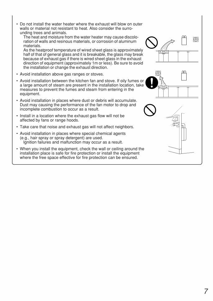
• Do not install the water heater where the exhaust will blow on outerwalls or material not resistant to heat. Also consider the surro-unding trees and animals.
The heat and moisture from the water heater may cause discolo-ration of walls and resinous materials, or corrosion of aluminummaterials.As the heatproof temperature of wired sheet glass is approximatelyhalf of that of general glass and it is breakable, the glass may breakbecause of exhaust gas if there is wired sheet glass in the exhaustdirection of equipment (approximately 1m or less). Be sure to avoidthe installation or change the exhaust direction.
• Avoid installation above gas ranges or stoves.
• Avoid installation between the kitchen fan and stove. If oily fumes ora large amount of steam are present in the installation location, takemeasures to prevent the fumes and steam from entering in theequipment.
• Avoid installation in places where dust or debris will accumulate.Dust may causing the performance of the fan motor to drop andincomplete combustion to occur as a result.
• Install in a location where the exhaust gas flow will not beaffected by fans or range hoods.
• Take care that noise and exhaust gas will not affect neighbors.
• Avoid installation in places where special chemical agents(e.g., hair spray or spray detergent) are used.
Ignition failures and malfunction may occur as a result.
• When you install the equipment, check the wall or ceiling around theinstallation place is safe for fire protection or install the equipmentwhere the free space effective for fire protection can be ensured.
8
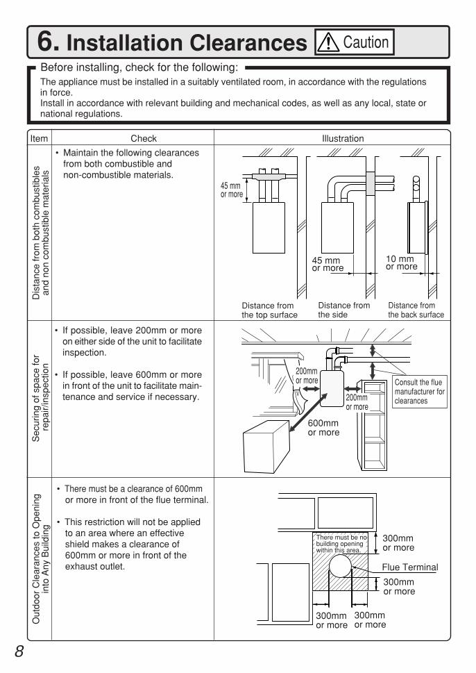
6. Installation ClearancesBefore installing, check for the following:The appliance must be installed in a suitably ventilated room, in accordance with the regulationsin force.Install in accordance with relevant building and mechanical codes, as well as any local, state ornational regulations.
Item
Dis
tanc
e fr
om b
oth
com
bust
ible
san
d no
n co
mbu
stib
le m
ater
ials
• Maintain the following clearancesfrom both combustible andnon-combustible materials.
• There must be a clearance of 600mmor more in front of the flue terminal.
• This restriction will not be appliedto an area where an effectiveshield makes a clearance of600mm or more in front of theexhaust outlet.
Check Illustration
Caution
• If possible, leave 200mm or moreon either side of the unit to facilitateinspection.
• If possible, leave 600mm or morein front of the unit to facilitate main-tenance and service if necessary.
Sec
urin
g of
spa
ce fo
r r
epai
r/in
spec
tion
600mmor more
200mmor more
Out
door
Cle
aran
ces
to O
peni
ngin
to A
ny B
uild
ing
Distance fromthe top surface
Distance fromthe side
45 mmor more
45 mmor more
Consult the fluemanufacturer forclearances
300mmor more
300mmor more
300mmor more
There must be nobuilding openingwithin this area.
300mmor more
Flue Terminal
200mmor more
Distance fromthe back surface
10 mmor more
9
Illustration
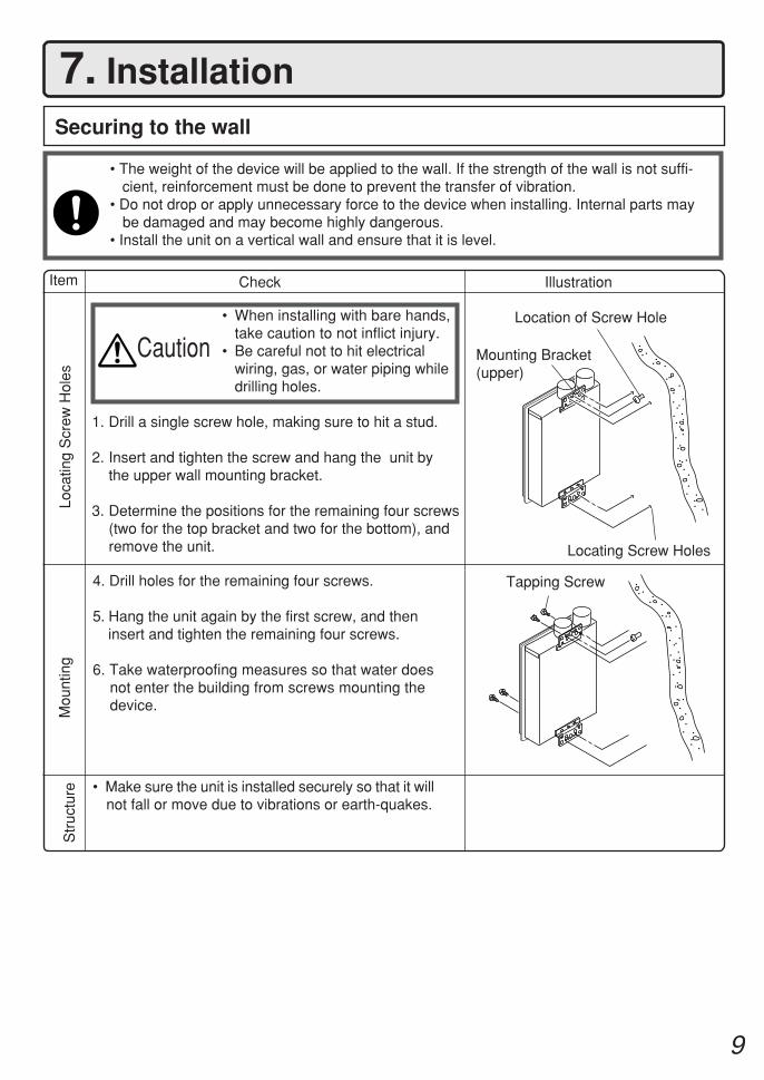
7. Installation
Check
4. Drill holes for the remaining four screws.
5. Hang the unit again by the first screw, and theninsert and tighten the remaining four screws.
6. Take waterproofing measures so that water doesnot enter the building from screws mounting thedevice.
• Make sure the unit is installed securely so that it willnot fall or move due to vibrations or earth-quakes.
Securing to the wall
Mounting Bracket(upper)
Tapping Screw
Location of Screw Hole
1. Drill a single screw hole, making sure to hit a stud.
2. Insert and tighten the screw and hang the unit bythe upper wall mounting bracket.
3. Determine the positions for the remaining four screws(two for the top bracket and two for the bottom), andremove the unit.
• The weight of the device will be applied to the wall. If the strength of the wall is not suffi- cient, reinforcement must be done to prevent the transfer of vibration.• Do not drop or apply unnecessary force to the device when installing. Internal parts may
be damaged and may become highly dangerous.• Install the unit on a vertical wall and ensure that it is level.
Locating Screw Holes
Loca
ting
Scr
ew H
oles
Mou
ntin
gS
truc
ture
Caution• When installing with bare hands,
take caution to not inflict injury.• Be careful not to hit electrical
wiring, gas, or water piping whiledrilling holes.
Item
10
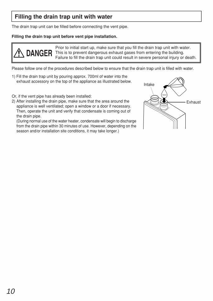
Filling the drain trap unit with water
The drain trap unit can be filled before connecting the vent pipe.
Filling the drain trap unit before vent pipe installation.
DANGERPrior to initial start up, make sure that you fill the drain trap unit with water.This is to prevent dangerous exhaust gases from entering the building.Failure to fill the drain trap unit could result in severe personal injury or death.
Please follow one of the procedures described below to ensure that the drain trap unit is filled with water.
700ml
Intake
Exhaust
1) Fill the drain trap unit by pouring approx. 700ml of water into theexhaust accessory on the top of the appliance as illustrated below.
Or, if the vent pipe has already been installed:2) After installing the drain pipe, make sure that the area around the
appliance is well ventilated; open a window or a door if necessary.Then, operate the unit and verify that condensate is coming out ofthe drain pipe.(During normal use of the water heater, condensate will begin to dischargefrom the drain pipe within 30 minutes of use. However, depending on theseason and/or installation site conditions, it may take longer.)
11
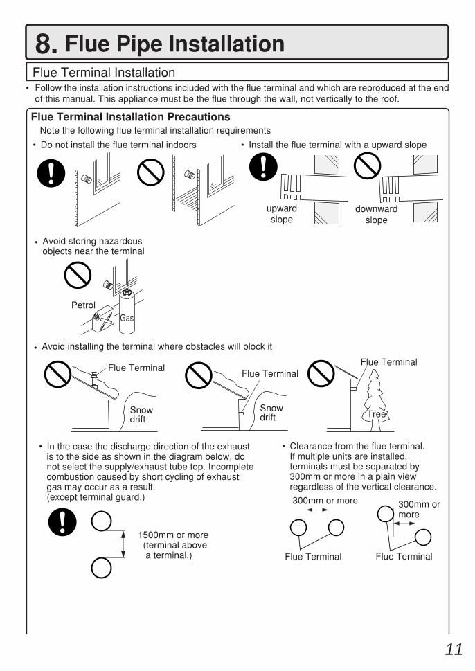
Flue Terminal Installation PrecautionsNote the following flue terminal installation requirements
• Do not install the flue terminal indoors • Install the flue terminal with a upward slope
upwardslope
downwardslope
• Avoid storing hazardousobjects near the terminal
PetrolGas
Flue TerminalFlue Terminal
Snowdrift Tree
• Avoid installing the terminal where obstacles will block it
• Clearance from the flue terminal. If multiple units are installed,
terminals must be separated by300mm or more in a plain viewregardless of the vertical clearance.
Flue Terminal Flue Terminal
300mm or more 300mm ormore
• In the case the discharge direction of the exhaustis to the side as shown in the diagram below, donot select the supply/exhaust tube top. Incompletecombustion caused by short cycling of exhaustgas may occur as a result.
(except terminal guard.)
8. Flue Pipe InstallationFlue Terminal Installation
• Follow the installation instructions included with the flue terminal and which are reproduced at the endof this manual. This appliance must be the flue through the wall, not vertically to the roof.
1500mm or more (terminal above
a terminal.)
Flue Terminal
Snowdrift
12
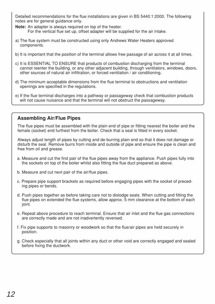
Detailed recommendations for the flue installations are given in BS 5440:1:2000. The followingnotes are for general guidance only.Note: An adapter is always required on top of the heater.
For the vertical flue set up, offset adapter will be supplied for the air intake.
a) The flue system must be constructed using only Andrews Water Heaters approvedcomponents.
b) It is important that the position of the terminal allows free passage of air across it at all times.
c) It is ESSENTIAL TO ENSURE that products of combustion discharging from the terminalcannot reenter the building, or any other adjacent building, through ventilators, windows, doors,other sources of natural air infiltration, or forced ventilation / air conditioning.
d) The minimum acceptable dimensions from the flue terminal to obstructions and ventilationopenings are specified in the regulations.
e) If the flue terminal discharges into a pathway or passageway check that combustion productswill not cause nuisance and that the terminal will not obstruct the passageway.
a. Measure and cut the first pair of the flue pipes away from the appliance. Push pipes fully intothe sockets on top of the boiler whilst also fitting the flue duct prepared as above.
b. Measure and cut next pair of the air/flue pipes.
c. Prepare pipe support brackets as required before engaging pipes with the socket of preced-ing pipes or bends.
d. Push pipes together as before taking care not to dislodge seals. When cutting and fitting theflue pipes on extended the flue systems, allow approx. 5 mm clearance at the bottom of eachjoint.
e. Repeat above procedure to reach terminal. Ensure that air inlet and the flue gas connectionsare correctly made and are not inadvertently reversed.
f. Fix pipe supports to masonry or woodwork so that the flue/air pipes are held securely inposition.
g. Check especially that all joints within any duct or other void are correctly engaged and sealedbefore fixing the ductwork.
The flue pipes must be assembled with the plain end of pipe or fitting nearest the boiler and thefemale (socket) end furthest from the boiler. Check that a seal is fitted in every socket.
Always adjust length of pipes by cutting and de-burring plain end so that it does not damage ordisturb the seal. Remove burrs from inside and outside of pipe and ensure the pipe is clean andfree from oil and grease.
Assembling Air/Flue Pipes
13
720
720
Max
imum
leng
th 1
745
Max
imum
leng
th 1
2000
with
1 x
90°
ben
dM
axim
um le
ngth
700
0 w
ith 4
x 9
0 ° b
ends
Max
imum
leng
th 1
745
Pitched roofStraight roof
Air and flue adapter
720
720
150
150
315
125
Special adapter
Pitched roof
Flat roof
Heater to flue adapter
Air and flue adapter
Max
imum
leng
th 1
745
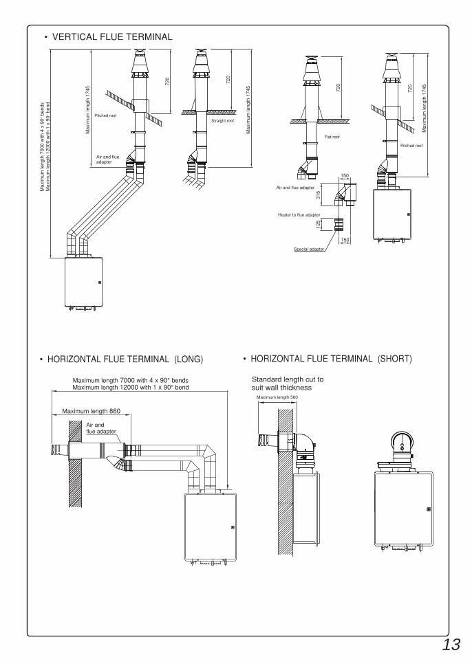
Maximum length 12000 with 1 x 90° bendMaximum length 7000 with 4 x 90° bends
Maximum length 860
Air and flue adapter
• HORIZONTAL FLUE TERMINAL (LONG)
• VERTICAL FLUE TERMINAL
• HORIZONTAL FLUE TERMINAL (SHORT)
suit wall thicknessStandard length cut to
Maximum length 560
14
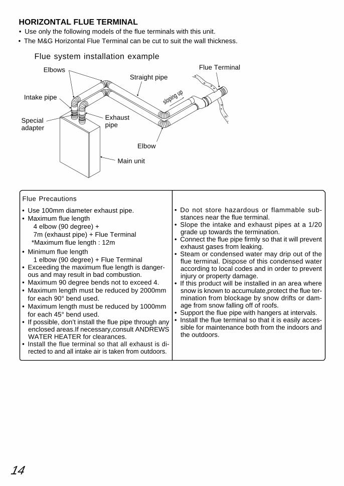
Main unit
Straight pipe
• Do not store hazardous or flammable sub-stances near the flue terminal.
• Slope the intake and exhaust pipes at a 1/20grade up towards the termination.
• Connect the flue pipe firmly so that it will preventexhaust gases from leaking.
• Steam or condensed water may drip out of theflue terminal. Dispose of this condensed wateraccording to local codes and in order to preventinjury or property damage.
• If this product will be installed in an area wheresnow is known to accumulate,protect the flue ter-mination from blockage by snow drifts or dam-age from snow falling off of roofs.
• Support the flue pipe with hangers at intervals.• Install the flue terminal so that it is easily acces-
sible for maintenance both from the indoors andthe outdoors.
Flue Precautions
• Use 100mm diameter exhaust pipe.• Maximum flue length 4 elbow (90 degree) + 7m (exhaust pipe) + Flue Terminal *Maximum flue length : 12m• Minimum flue length 1 elbow (90 degree) + Flue Terminal• Exceeding the maximum flue length is danger-
ous and may result in bad combustion.• Maximum 90 degree bends not to exceed 4.• Maximum length must be reduced by 2000mm
for each 90° bend used.• Maximum length must be reduced by 1000mm
for each 45° bend used.• If possible, don’t install the flue pipe through any
enclosed areas.If necessary,consult ANDREWSWATER HEATER for clearances.
• Install the flue terminal so that all exhaust is di-rected to and all intake air is taken from outdoors.
Elbows
Elbow
Flue Terminal
sloping upIntake pipe
Exhaustpipe
Flue system installation example
HORIZONTAL FLUE TERMINAL• Use only the following models of the flue terminals with this unit.• The M&G Horizontal Flue Terminal can be cut to suit the wall thickness.
Specialadapter
15
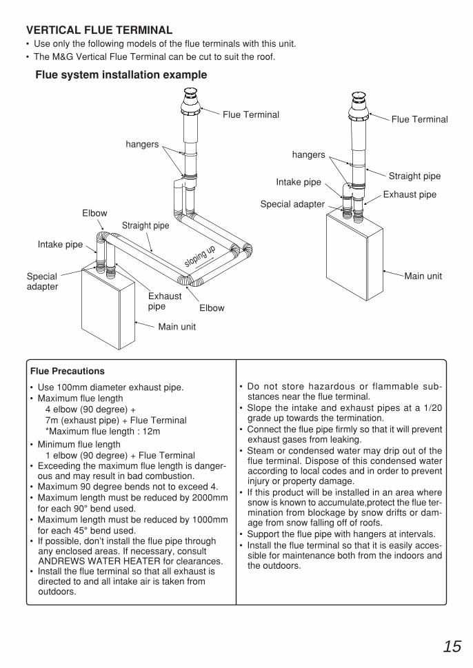
Main unit
Straight pipe
• Do not store hazardous or flammable sub-stances near the flue terminal.
• Slope the intake and exhaust pipes at a 1/20grade up towards the termination.
• Connect the flue pipe firmly so that it will preventexhaust gases from leaking.
• Steam or condensed water may drip out of theflue terminal. Dispose of this condensed wateraccording to local codes and in order to preventinjury or property damage.
• If this product will be installed in an area wheresnow is known to accumulate,protect the flue ter-mination from blockage by snow drifts or dam-age from snow falling off of roofs.
• Support the flue pipe with hangers at intervals.• Install the flue terminal so that it is easily acces-
sible for maintenance both from the indoors andthe outdoors.
Flue Precautions
• Use 100mm diameter exhaust pipe.• Maximum flue length 4 elbow (90 degree) + 7m (exhaust pipe) + Flue Terminal *Maximum flue length : 12m• Minimum flue length 1 elbow (90 degree) + Flue Terminal• Exceeding the maximum flue length is danger-
ous and may result in bad combustion.• Maximum 90 degree bends not to exceed 4.• Maximum length must be reduced by 2000mm
for each 90° bend used.• Maximum length must be reduced by 1000mm
for each 45° bend used.• If possible, don’t install the flue pipe through
any enclosed areas. If necessary, consultANDREWS WATER HEATER for clearances.
• Install the flue terminal so that all exhaust isdirected to and all intake air is taken fromoutdoors.
Elbow
Elbow
Flue Terminal
sloping upIntake pipe
Exhaustpipe
Flue system installation example
VERTICAL FLUE TERMINAL• Use only the following models of the flue terminals with this unit.
Specialadapter
Main unit
Straight pipe
Flue Terminal
Intake pipeExhaust pipe
hangershangers
• The M&G Vertical Flue Terminal can be cut to suit the roof.
Special adapter
16
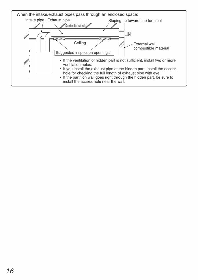
(Combustible material)
Intake pipe
External wall,combustible material
• If the ventilation of hidden part is not sufficient, install two or moreventilation holes.
• If you install the exhaust pipe at the hidden part, install the accesshole for checking the full length of exhaust pipe with eye.
• If the partition wall goes right through the hidden part, be sure toinstall the access hole near the wall.
Suggested inspection openings
When the intake/exhaust pipes pass through an enclosed space:
Ceiling
Sloping up toward flue terminalExhaust pipe
17
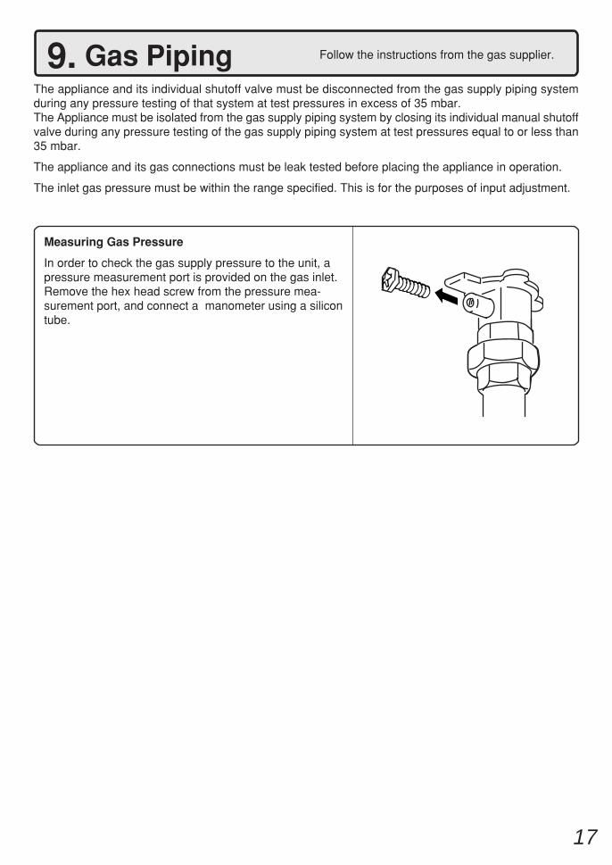
Measuring Gas Pressure
In order to check the gas supply pressure to the unit, apressure measurement port is provided on the gas inlet.Remove the hex head screw from the pressure mea-surement port, and connect a manometer using a silicontube.
Follow the instructions from the gas supplier.9. Gas PipingThe appliance and its individual shutoff valve must be disconnected from the gas supply piping systemduring any pressure testing of that system at test pressures in excess of 35 mbar.The Appliance must be isolated from the gas supply piping system by closing its individual manual shutoffvalve during any pressure testing of the gas supply piping system at test pressures equal to or less than35 mbar.
The appliance and its gas connections must be leak tested before placing the appliance in operation.
The inlet gas pressure must be within the range specified. This is for the purposes of input adjustment.
18
10. Water PipingThis appliance is suitable for potable water. Do not use this appliance if any part has been underwater. Immediatelycall a qualified service technician to inspect the appliance and replace any part of the control system and gas controlwhich has been under water.
If the water heater is installed in a closed water supply system, such as one having a backflow preventer in the coldwater supply line, means shall be provided to control thermal expansion. Contact ANDREWS WATER HEATERSTECHNICAL DEPARTMENT FOR ADVICE.
Piping and components connected to the water heater shall be suitable for use with potable water.Toxic chemicals, such as those used for boiler treatment, shall not be introduced into the potable water.A water heater used to supply potable water may not be connected to any heating system or components previouslyused with a nonpotable water heating appliance.When water is required in one part of the system at a higher temperature than in the rest of the system, means suchas a mixing valve shall be installed to temper the water to reduce the scalding hazard.
• Flush water through the pipe to clean out metal powder, sand and dirt before connecting it.• Take appropriate heat insulation measures (e.g., wrapping with heat insulation materials, using electric heaters)
according to the climate of the region to prevent the pipe from freezing.• Use a union coupling or flexible pipe for connecting the pipes to reduce the force applied to the piping.• Do not use piping with a diameter smaller than the coupling.• When feed water pressure is too high, insert a depressurizing valve, or take water hammer prevention measures.• Avoid using joints as much as possible to keep the piping simple.• Avoid piping in which an air holdup can occur.• Use approved piping materials.• If installing the unit on a roof:
If the unit is installed on a roof to supply water to the levels below, make sure that the water pressure supplied tothe unit does not drop below 2000 mbar. It may be necessary to install a pump system to ensure that the waterpressure is maintained at this level.Check the pressure before putting the unit into operation.Failing to supply the proper pressure to the unit may result in noisy operation, shorter lifetime of the unit, andmay cause the unit to shut down frequently.
Supply water piping• Do not use PVC piping.• Mount a check valve and a shut off valve (near
the inlet).• In order for the client to use the water heater
comfortably,1000 mbar to 5000 mbar of pres-sure is needed from the water supply.Be sure to check the water pressure. If the waterpressure is low, the water heater cannot performto its full capability, and may become a source oftrouble for the client.
Drain piping• Expansion water may drop from the pressure
prevention device and wet the floor. If neces-sary, provide drain piping or use a drain hose toremove the water.
Hot water piping• Do not use lead or PVC piping.• The longer the piping, the greater the heat loss.
Try to make the piping as short as possible.• Use a mixing valve with a low water resistance.
Use shower heads with low pressure loss.• If necessary, use a pump or other means to en-
sure that the supply water pressure to the inletof the heater does not fall below 2000 mbar whenthe maximum amount of water is being de-manded. Also install a pressure meter on the in-let. If this is not done, local boiling will occur in-side the water heater causing abnormal soundsand decreasing the durability of the heat ex-changer.
Ask a qualified plumber to perform the installationof the plumbing. Observe all applicable codes.
19
Do not connect electrical power to the unit until all electrical wiring has been completed.
Consult a qualified electricianfor the electrical work.11. Electrical Wiring
Do not turn on the power until the electrical wiring is finished.This may cause electrical shock or damage to the equipment to occur.
i) "A means of disconnection from the supply mains having a contact separation in all poles must be pro-vided to allow for full disconnection".
ii) Under voltage Cat III conditions should be incorporated in the fixed wiring in accordance with the wiringregulations.
iii) "If the supply cord is damaged, it must be replaced by the manufacturer or its service agent".
This appliance must be electrically grounded in accordance with Electrical Authority Regulations.
External wiring must be correctly earthed, polarised and in accordance with the relevant standards.
In GB this is BS 6891.
In IE this is the current edition of I.S.813 "Domestic Gas Installations".
The boiler must be connected to a permanent 230 V ac, 50Hz supply.
Connection of the whole electrical system of the boiler, including any heating controls, to the electrical supplymust be through one common isolator and must be fused 10 Amp maximum.
Isolation should be by a double pole switched fused spur box, with a minimum gap of 3 mm for both poles.The fused spur box should be readily accessible and preferably adjacent to the appliance. It should beidentified as to its use.
Caution: Label all wires prior to disconnection when servicing controls. Wiring errors can cause improperand dangerous operation.
Verify proper operation after servicing.
Field wiring to be performed at time of appliance installation.
Caution
• The electrical supply required by the waterheater is 230V AC at 50 Hz.As the electric power consumption variesdepending on the gas type, check it with therating plate or higher if using optional accessories.Use an appropriate circuit.
• Do not disconnect the power supply when notin use. When the power is off, the freezeprevention in the water heater will not acti-vate, resulting in possible freezing damage.
• Do not let the power cord contact the gas piping.
Tie the redundant power cord outside thewater heater. Putting the redundant length ofcord inside the water heater may cause elec-trical interference and faulty operation.
Ground• To prevent an electric shock, always plug power
lead into an earth powerpoint.THE APPLIANCE MUST BE EARTHED
20
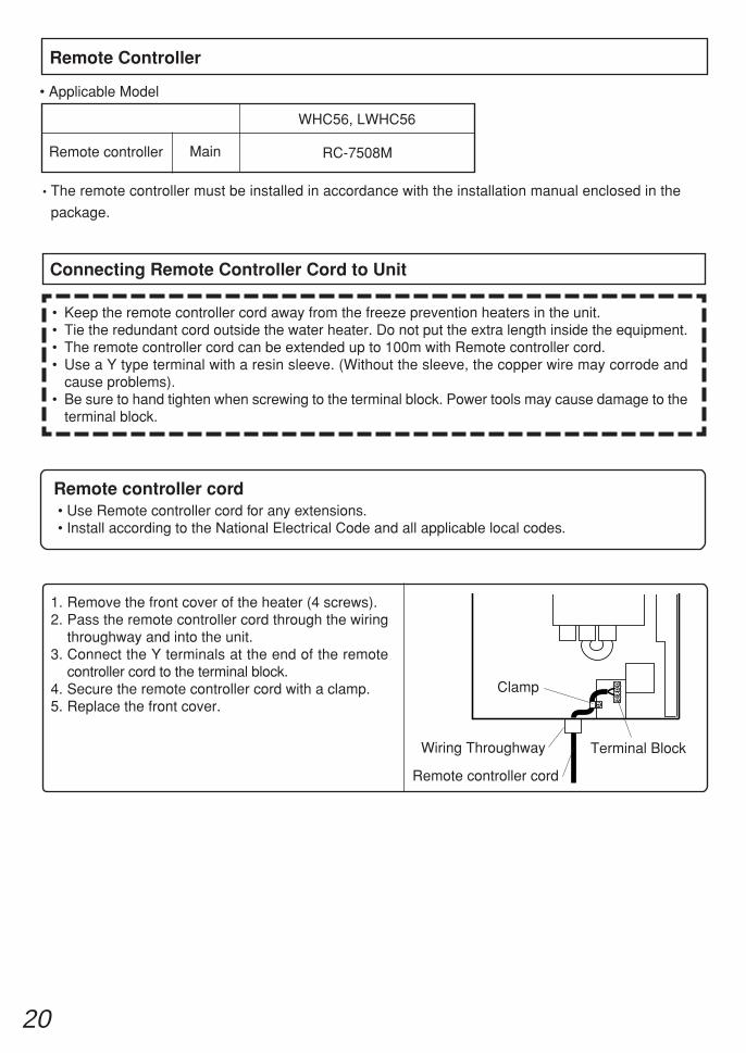
1. Remove the front cover of the heater (4 screws).2. Pass the remote controller cord through the wiring
throughway and into the unit.3. Connect the Y terminals at the end of the remote
controller cord to the terminal block.4. Secure the remote controller cord with a clamp.5. Replace the front cover.
Remote controller cord
Remote controller cord• Use Remote controller cord for any extensions.• Install according to the National Electrical Code and all applicable local codes.
Connecting Remote Controller Cord to Unit
• Keep the remote controller cord away from the freeze prevention heaters in the unit.• Tie the redundant cord outside the water heater. Do not put the extra length inside the equipment.• The remote controller cord can be extended up to 100m with Remote controller cord.• Use a Y type terminal with a resin sleeve. (Without the sleeve, the copper wire may corrode and
cause problems).• Be sure to hand tighten when screwing to the terminal block. Power tools may cause damage to the
terminal block.
Clamp
Terminal BlockWiring Throughway
• Applicable Model
Remote Controller
Remote controller RC-7508M
WHC56, LWHC56
Main
• The remote controller must be installed in accordance with the installation manual enclosed in the
package.
21
Shutdown Instructions1. Stop any water demand.2. Turn off electric power.3. Turn the gas control manual valve clockwise to the off position.
Should overheating occur, or the gas supply fail to shut off, turn off the gas control manual valve tothe appliance.
Handling after trial operation• In Freezing areas: If the unit will not be used immediately, close off all gas and water shutoff
valves, drain all of the water out of the unit and the plumbing system to prevent the unitand system from freezing, and bleed the gas out of the gas line.Freezing is not covered by the warranty.
Caution
(1) Open a hot water fixture and confirm that the Burner On indicator comes on, and that hot wateris being produced. (If necessary, repeat until the air in the gas piping is bled out).* White smoke may be noticed from the exhaust pipe during cold weather. However, this is not a
malfunction of the unit.* If an “11” error code appears on the remote controller, turn the unit off and then back on again,
and then open a hot water fixture again.(2) Change the temperature setting on the remote controller and check that the water temperature changes.
• If the water heater does not operate normally, refer to "Troubleshooting"in the Operation Manual.
* After the trial operation, clean the filter in the cold water inlet.
12. CommissioningThe installer should test operate the unit, explain tothe customer how to use the unit, and give the ownerthis manual before leaving the installation
• Preparation ... (1) Ensure all lines are purged / flushed of debris prior to connection to appliance.(2) Open the shut off valve on the water supply, check that water passes through the
valve and close the valve.(3) Open the gas supply valve, turn on the power supply, and turn on the Operation
switch on the remote controller (the Operation lamp turns on) .
NOTE: The appliance has been factory set and no adjustment is necessary.
<If installed with a quick connect multi-system>• Turn the system power on with the remote controller.• Slowly open a hot water fixture and check that the units ignite sequentially. Check to see that the
hot water temperature is the same as the temperature displayed on the remote controller. (*1)
* If inlet water temperature is high, and both units do not ignite at the same time, switch whichunit will ignite first by pressing the Max. or Min. Manifold Pressure Set Button on the circuitboard and then confirm each unit can ignite. (*2)
* If an 11 or F11 error code flashes on the remote controller, hit the Power Button on the remotecontroller off and on 2-3 times.
* If (*1) and (*2) cannot be done, the Quick Connect Cord may not be properly connected.Check that the cord is properly connected.
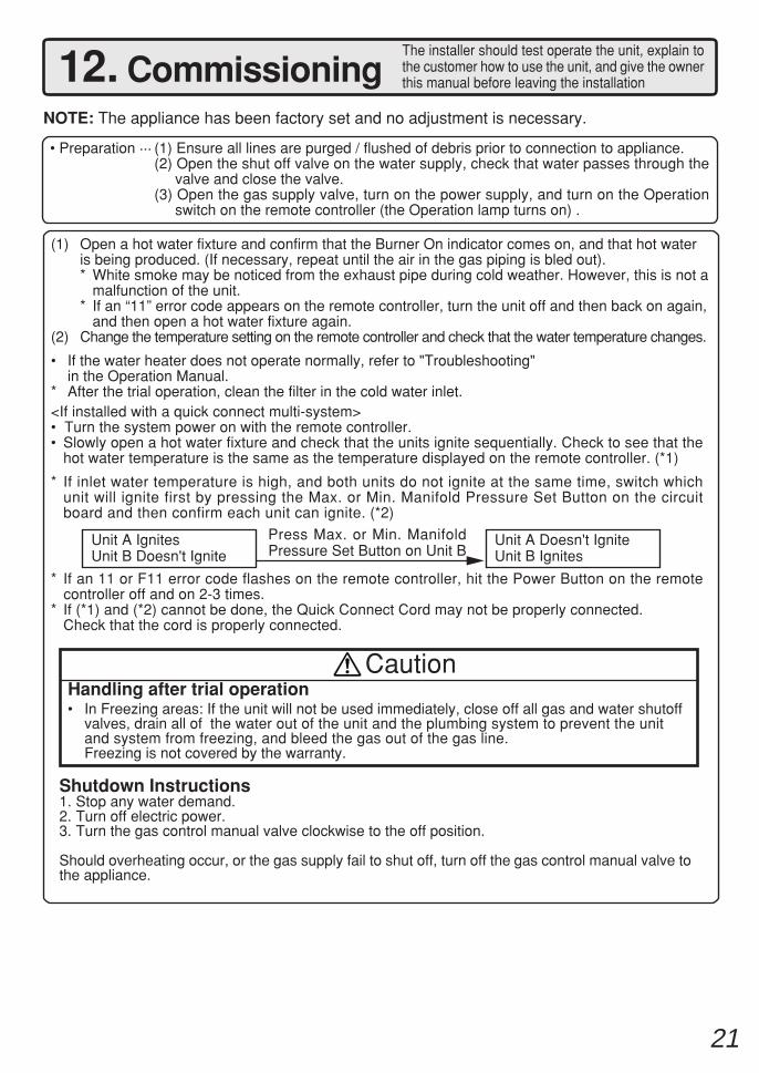
Unit A IgnitesUnit B Doesn't Ignite
Press Max. or Min. ManifoldPressure Set Button on Unit B
Unit A Doesn't IgniteUnit B Ignites
22
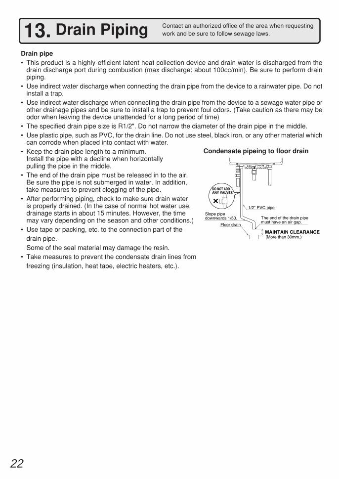
13. Drain PipingDrain pipe• This product is a highly-efficient latent heat collection device and drain water is discharged from the
drain discharge port during combustion (max discharge: about 100cc/min). Be sure to perform drainpiping.
• Use indirect water discharge when connecting the drain pipe from the device to a rainwater pipe. Do notinstall a trap.
• Use indirect water discharge when connecting the drain pipe from the device to a sewage water pipe orother drainage pipes and be sure to install a trap to prevent foul odors. (Take caution as there may beodor when leaving the device unattended for a long period of time)
• The specified drain pipe size is R1/2". Do not narrow the diameter of the drain pipe in the middle.• Use plastic pipe, such as PVC, for the drain line. Do not use steel, black iron, or any other material which
can corrode when placed into contact with water.• Keep the drain pipe length to a minimum.
Install the pipe with a decline when horizontallypulling the pipe in the middle.
• The end of the drain pipe must be released in to the air.Be sure the pipe is not submerged in water. In addition,take measures to prevent clogging of the pipe.
• After performing piping, check to make sure drain wateris properly drained. (In the case of normal hot water use,drainage starts in about 15 minutes. However, the timemay vary depending on the season and other conditions.)
• Use tape or packing, etc. to the connection part of thedrain pipe.Some of the seal material may damage the resin.
• Take measures to prevent the condensate drain lines fromfreezing (insulation, heat tape, electric heaters, etc.).
Contact an authorized office of the area when requestingwork and be sure to follow sewage laws.
Slope pipe downwards 1/50.
1/2" PVC pipe
The end of the drain pipe must have an air gap.
MAINTAIN CLEARANCE
Floor drain
(More than 30mm.)
DO NOT ADDANY VALVES
Condensate pipeing to floor drain
23
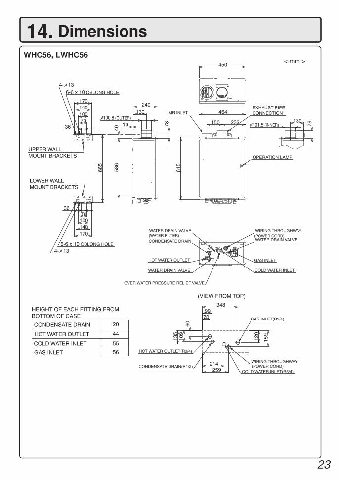
14. DimensionsWHC56, LWHC56
< mm >
20
44
55
GAS INLET 56
232150
464
615
AIR INLET130
78
240
10
586
450
(POWER CORD)
GAS INLET
130
79
40
665
3670100140170
3670100140170
6-6 x 10 OBLONG HOLE
100.8 (OUTER)
4- 13
6-6 x 10 OBLONG HOLE
70
214259
348
6010
913
5
99
120
159
GAS INLET(R3/4)
UPPER WALL MOUNT BRACKETS
LOWER WALL MOUNT BRACKETS
EXHAUST PIPE CONNECTION
OPERATION LAMP
4- 13
WATER DRAIN VALVE
CONDENSATE DRAIN(WATER FILTER)
HOT WATER OUTLET
WATER DRAIN VALVE
OVER WATER PRESSURE RELIEF VALVE
WIRING THROUGHWAY
WATER DRAIN VALVE
COLD WATER INLET
HOT WATER OUTLET(R3/4)
CONDENSATE DRAIN(R1/2)WIRING THROUGHWAY(POWER CORD)
COLD WATER INLET(R3/4)
(VIEW FROM TOP)
HEIGHT OF EACH FITTING FROM BOTTOM OF CASE
CONDENSATE DRAIN
HOT WATER OUTLET
COLD WATER INLET
101.5 (INNER)
24
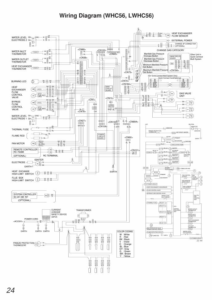
Wiring Diagram (WHC56, LWHC56)
RELAY 10
FLAME RODFR
DU
EARTH D
GND
AIR INLETTHERMISTOR
HEAT EXCHANGER THERMISTOR
<CN1>
BK BL
RC-7508M
EARTH
V : Violet
BL : BlueO : Orange
G : GreenBR : BrownY : Yellow
GY : Gray
COLOR CODING
R : RedBK : Black
W : White
HEAT EXCANGEHIGH-LIMIT SWITCH
ELECTRODEBK
W
IGNITER
WW
WW
REMOTE CONTROLLER
FAN MOTOR
FLAME ROD
THERMAL FUSE
HEATEXCHANGERFLOWCONTROLVALVE
SM
LS
SM
LS
FM
IG
BYPASSFLOWCONTROLVALVE
RR(VCC)
BR(Vs)
R(Vcc)BL(GND)Y(FG)
BLBL
BL
BL
(Fully open)(GND)
BL
Y YBL
BLY
R
BR
BLY
R
BR
BR RBLY
<CN27>
WW(VCC)
BK
(VCC)V
GO
W
(Fully open)(VCC)
(GND)
RO
Y
G
BL
GO
VBK
Y
OR
G
BL
BKV
BKV
<CN78>BL
BL
HEAT EXCHANGER THERMISTOR
WATER OUTLETTHERMISTOR
WATER INLETTHERMISTOR
WW
WW
WW
WW
WWW
WW
BK V
OY
Y
V
R
R
G
G O
<CN38>
BLR
<CN89>BL
BL
RELAY 9 IGNITER
<CN101>
DC15V
DC90V
FLOW CONTROL VALVE
15V POWER CIRCUIT
BYPASS FLOW CONTROL VALVE
HEAT EXCHANGER FLOW SENSOR
THERMAL FUSE
GND
EARTH
BKW
FAN PULSE CONTROL CIRCUIT
CENTRAL PROCESSING UNITRELAY 5
RELAY 7
RELAY 3
RELAY 1
RELAY DRIVING CIRCUIT
CPU
Sub-CPU SUB CONTROL UNIT
WATER INLETTHERMISTOR
WATER OUTLETTHERMISTOR
D
FAN CURRENT VALUE INPUT
FAN ROTATION SPEED INPUT
B
C
SOLENOIDVALVE Q3
SOLENOIDVALVE Q2
SOLENOIDVALVE Q1
SOLENOIDVALVE 0
SECONDARY
PRIMARY
DC12V
C
RELAY 10
SV3
SV2
RELAY 5
RELAY 4
SV0
SV1
IG
RELAY 1
RELAY 3
FAN CONTROL OUTPUT
COMBUTION FAN
A
B
A
HIGH LIMIT SWITCH
DC90V
32
4
65
BL
POWERCIRCUIT BOARD
<CN104>
YW W O
G
<CN102>
<CN92>
BL W
<CN89A>
BLBL
BLBLR
HOT
<CN10>
WG
BKW
GYWBK BL
BKO
MAINCIRCUIT BOARD
O
GYW
BL
BK
W
RBK
<CN184>
GBLBL
1
32
4
65
7
9101112131415
8
1
1 2 3 4 5 61 2 3 4 5 6 7 8 9
32
4
65
1
321
R
RBL
BK
GBLBL
W
Q3
SECONDARY
PRIMARY
CIRCULATION PUMPRELAY 7
AC100V
AC230V
10A(FUSE)
NEUTRAL
O
SVO W
4GY
BL
3
5
BK1W2
W 010
BL78
6R
321
4
BL
RDU
11
12
13
GY
GY
O
BK
BK
Q2SV
SV
Q1SV
GAS VALVEUNIT
3
12
4
Manifold Gas Pressure Decrease Button
Manifold Gas Pressure Increase Button
Maximum Manifold PressureSet Button
Minimum Manifold PressureSet Button
BL
<CN102>
W Y OR
W
<CN63>
WW W
<CN75>
<CN70>W
YR
Y
BL
EXTERNAL POWER
<CN184>
MAIN CIRCUIT BOARD
Other Unit in Quick Connect Multi System
Quick Connect Cord(Optional)(For Quick Connect Multi System Only)
65
1843W W32
BLBL
BKR1
2 BKR
65
1
54
6
G
BLBL5
4
6
G
BLBL
HEAT EXCHANGERFLOW SENSOR (GND)
(Vcc)(Pulse)
RY
BLRBL
YQS
BLBL
RC TERMINAL
DC140V
DC140V
W
BL
W
BLBL
BL
W
BL
BL
BLBL
GAS PROPORTION VALVE POWER CONTROL CIRCUIT
FLAME DETECTING CIRCUIT
5V POWER CIRCUIT
<AC230V>
WW
WW
BRBL
EARTH
Y/G
BL BLW W
CURRENT LEAKAGE SAFETY DEVICE(GFCI)
TRANSFORMER
W
W
EARTH
Y/G
BRBL
BR
BLGYGY
BL
W WWW
W W WW
WW W W
WW WWFREEZE PROTECTION THERMOSTAT
POWER CORD
EARTH
Y/G
W WWW
W W WW
WW W W
WW WW
BR
BR
R
R
R
CHANGE GAS CATEGORY
FLUE BOX HIGH-LIMIT SWITCH
WW
WW
BURNING LED WWBK BK
BK
WG
WATER LEVEL ELECTRODE 1
(GND)
VV
WGWW
W
W
R
WATER LEVEL ELECTRODE 2
(GND)
RR
WR
23
BLW
W
W
G
R
(OPTIONAL)
SYSTEM CONTROLLERSC-201-6M INT
(OPTIONAL)
B5 RBK
RBK
V
RR
CHANGE 3P CONNECTOR(OPTIONAL)
ANTI-FROST HEATERFREEZE PROTECTION VARISTOR
EARTH
VARISTORARRESTER
WATER LEVELELECTORODE 1
WATER LEVELELECTORODE 2
THERMOSTAT
1
23
1
23
1
234
1
21
21
21
43
65
87
21
43
21
21
21
123
21
21
43
21
3
1
1
1
2
65
87
23
123
1
2 23 1 1 21 21 21
12 12 12 12
FANPOWER CONTROLLER
(G)BK
(BK)G(R)W
(W)R
BLBL
G(BK)
BK(G)R(W)
W(R)
23
123
1
3
12
23
1
12345678910
12 1114 1316 1518 1720 1922 2124 2326 2528 2730 2932 31
1
1
1
1 2 3 45 6 7 8
234
56
2341234 1234 123
12
12
3
45
25
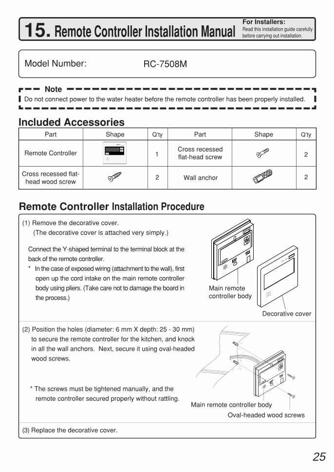
NoteDo not connect power to the water heater before the remote controller has been properly installed.
SETON / O
FF
SET
(1) Remove the decorative cover.
(The decorative cover is attached very simply.)
Connect the Y-shaped terminal to the terminal block at the
back of the remote controller.
* In the case of exposed wiring (attachment to the wall), first
open up the cord intake on the main remote controller
body using pliers. (Take care not to damage the board in
the process.)
Main remotecontroller body
Decorative cover
(2) Position the holes (diameter: 6 mm X depth: 25 - 30 mm)
to secure the remote controller for the kitchen, and knock
in all the wall anchors. Next, secure it using oval-headed
wood screws.
(3) Replace the decorative cover.
Oval-headed wood screws
* The screws must be tightened manually, and the
remote controller secured properly without rattling.Main remote controller body
15. Remote Controller Installation Manual
RC-7508MModel Number:
Included AccessoriesQ’tyShapePart
2
Part Shape Q’ty
Cross recessedflat-head screw
2
1
Cross recessed flat-head wood screw
2 Wall anchor
Remote Controller
Remote Controller Installation Procedure
For Installers:Read this installation guide carefullybefore carrying out installation.
26
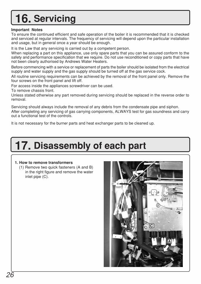
16. Servicing
17. Disassembly of each part
Important NotesTo ensure the continued efficient and safe operation of the boiler it is recommended that it is checkedand serviced at regular intervals. The frequency of servicing will depend upon the particular installationand usage, but in general once a year should be enough.It is the Law that any servicing is carried out by a competent person.When replacing a part on this appliance, use only spare parts that you can be assured conform to thesafety and performance specification that we require. Do not use reconditioned or copy parts that havenot been clearly authorised by Andrews Water Heaters.Before commencing with a service or replacement of parts the boiler should be isolated from the electricalsupply and water supply and the gas supply should be turned off at the gas service cock.All routine servicing requirements can be achieved by the removal of the front panel only. Remove thefour screws on the front panel and lift off.For access inside the appliances screwdriver can be used.To remove chassis front.Unless stated otherwise any part removed during servicing should be replaced in the reverse order toremoval.
Servicing should always include the removal of any debris from the condensate pipe and siphon.After completing any servicing of gas carrying components, ALWAYS test for gas soundness and carryout a functional test of the controls.
It is not necessary for the burner parts and heat exchanger parts to be cleaned up.
1. How to remove transformers(1) Remove two quick fasteners (A and B)
in the right figure and remove the waterinlet pipe (C). B
A
C
27
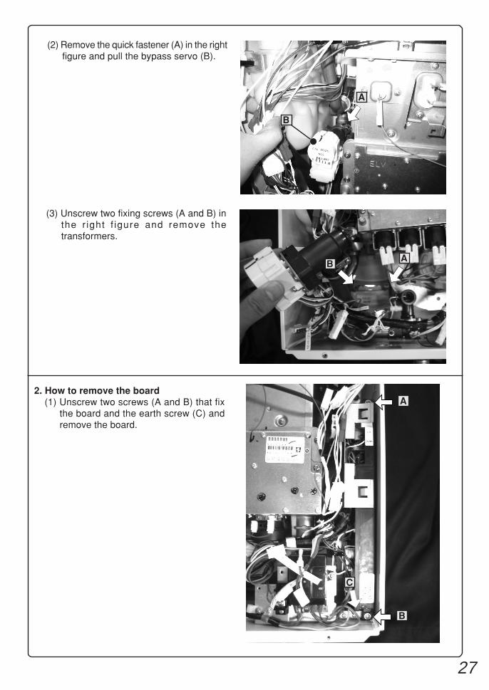
(2) Remove the quick fastener (A) in the rightfigure and pull the bypass servo (B).
B
A
(3) Unscrew two fixing screws (A and B) inthe r ight f igure and remove thetransformers.
2. How to remove the board(1) Unscrew two screws (A and B) that fix
the board and the earth screw (C) andremove the board.
A
B
C
BA
28
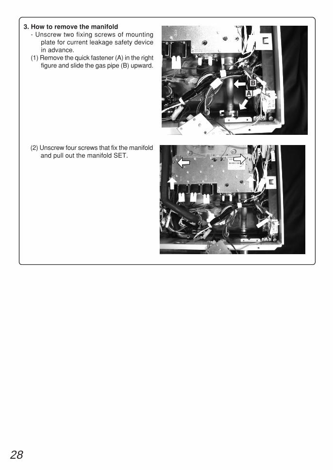
3. How to remove the manifold- Unscrew two fixing screws of mounting
plate for current leakage safety devicein advance.
(1) Remove the quick fastener (A) in the rightfigure and slide the gas pipe (B) upward.
(2) Unscrew four screws that fix the manifoldand pull out the manifold SET.
A
B
29
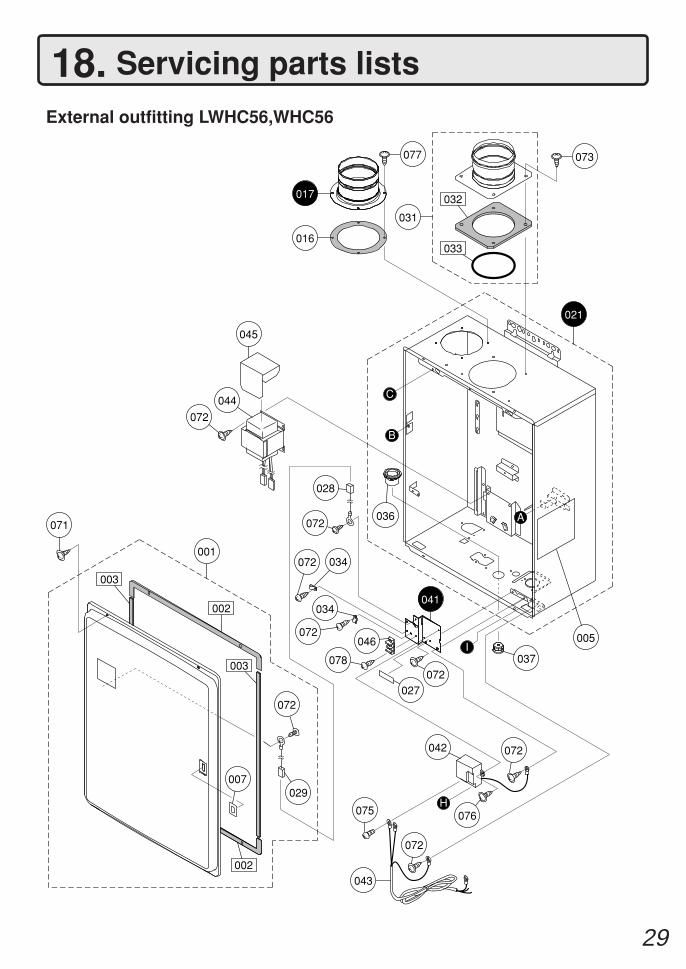
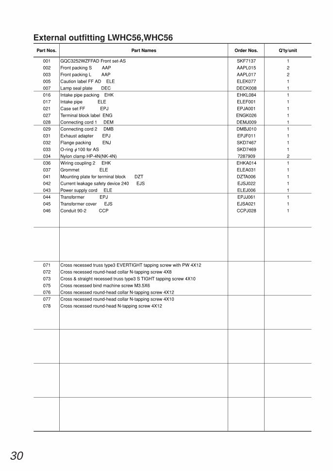
External outfitting LWHC56,WHC56
18. Servicing parts lists
003
002
002
003
001
005
073
072
044
045
071A
031
B
032
033
007
077
017
016
072
034072
046
078
034
072
028
072
042
076
072
075
043
072
072
029
027
021
C
H
041
I037
036
30
External outfitting LWHC56,WHC56
001 GQC3252WZFFAD Front set-AS SKF7137 1
002 Front packing S AAP AAPL015 2
003 Front packing L AAP AAPL017 2
005 Caution label FF AD ELE ELEK077 1
007 Lamp seal plate DEC DECK008 1
016 Intake pipe packing EHK EHKL084 1
017 Intake pipe ELE ELEF001 1
021 Case set FF EPJ EPJA001 1
027 Terminal block label ENG ENGK026 1
028 Connecting cord 1 DEM DEMJ009 1
029 Connecting cord 2 DMB DMBJ010 1
031 Exhaust adapter EPJ EPJF011 1
032 Flange packing ENJ SKD7467 1
033 O-ring 100 for AS SKD7469 1
034 Nylon clamp HP-4N(NK-4N) 7287909 2
036 Wiring coupling 2 EHK EHKA014 1
037 Grommet ELE ELEA031 1
041 Mounting plate for terminal block DZT DZTA006 1
042 Current leakage safety device 240 EJS EJSJ022 1
043 Power supply cord ELE ELEJ006 1
044 Transformer EPJ EPJJ061 1
045 Transformer cover EJS EJSA021 1
046 Conduit 90-2 CCP CCPJ028 1
071 Cross recessed truss type3 EVERTIGHT tapping screw with PW 4X12
072 Cross recessed round-head collar N-tapping screw 4X8
073 Cross & straight recessed truss type3 S TIGHT tapping screw 4X10
075 Cross recessed bind machine screw M3.5X6
076 Cross recessed round-head collar N-tapping screw 4X12
077 Cross recessed round-head collar N-tapping screw 4X10
078 Cross recessed round-head N-tapping screw 4X12
Part Nos. Part Names Order Nos. Q'ty/unit
31
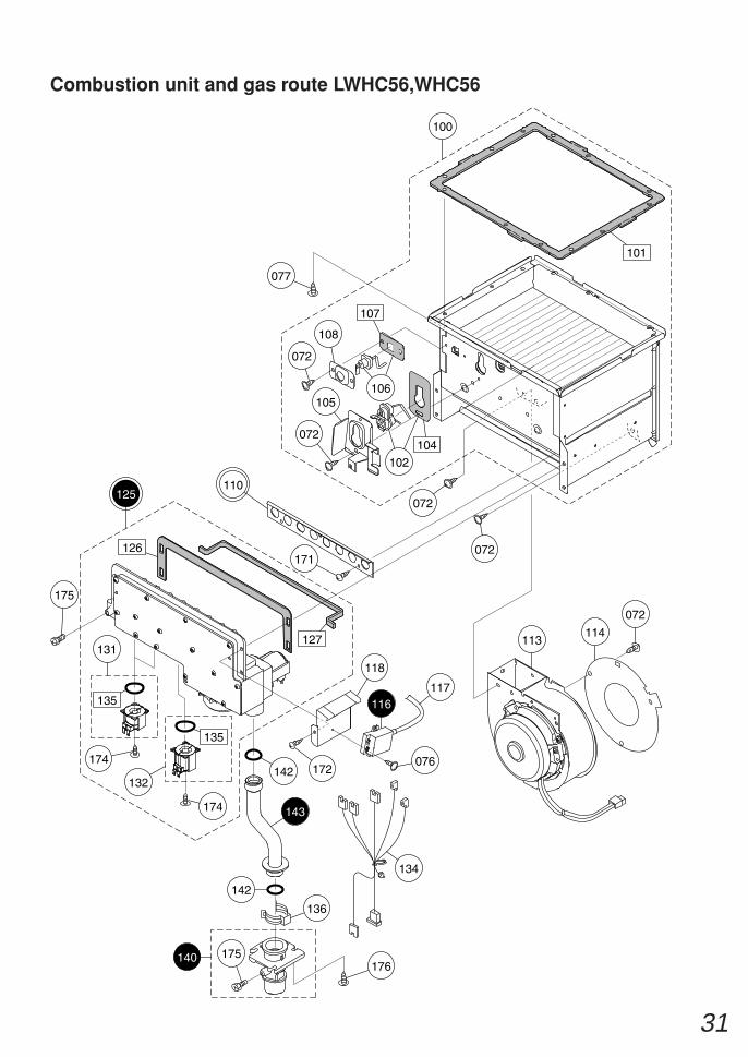
Combustion unit and gas route LWHC56,WHC56
140
143
116
072
113
102
106
108
072
072
072
072
105
171
172
175
175
142
136
176
142
107
104
127
135
135
126
100
077
101
131
134
132
174
174
114
076
118
117
125110
32
Combustion unit and gas route LWHC56,WHC56
100 Combustion tube set ELV SET-V SKC7447 1
101 Suction air joint packing ELV ELVL001 1
102 Ignition plug ELV & packing EHK SETV SKC7448 1
104 Plug packing H EHK EHKL002 1
105 Mounting plate for plug H EGL EGLC035 1
106 Flame rod ELV & packing DJP SETV SKC7449 1
107 Sensor packing DJP DJPL004 1
108 Sensor fixing plate DJP DJPC012 1
1<2H>110
113 Fan motor 110 EPJ(ADSE)SET-AS SKF7164 1
114 Bell-mouth 110 56 EHK EHKF423 1
116 Igniter AGV AGVJ007 1
117 High-voltage cord L370 ALS ALSJ071 1
118 Mounting plate for igniter EPJ EPJA021 1
1<2H>125 Gas mech. manifold 36 ELV SET-AS SKD7463
1<3P>Gas mech. manifold 23 ELV SET-AS SKD7462
126 Manifold seal packing top ELV ELVL003 1
127 Manifold seal packing bottom ELV ELVL007 1
131 Solenoid SO9L EBT SET-V SBP7501 2
132 Solenoid S16 CRU SET-V SBB7213 1
134 Gas mech. harness ELV ELVJ018 1
135 O-ring JASO 2030 type 1 SAA6044 3
136 Quick fastener 16B 6340407 1
140 Gas fitting 20A SET EPJ EPJE021 1
142 O-ring P18 2110903 2
143 Manifold pipe ENJ ENJE007 1
171 Cross recessed round-head N-tapping screw 4X8
172 Cross recessed round-head type3 EVERTIGHT tapping screw 5X16
174 Cross recessed round-head SPAK machine screw with guide M4X12
175 Cross recessed hexagon head machine screw M4X8
176 Cross recessed round-head collar type3 EVERTIGHT tapping screw 4X12
Part Nos. Part Names Order Nos. Q'ty/unit
Main damper 9-10 ELV ELVC055
1<3P>Main damper 11 ELV ELVC054
33
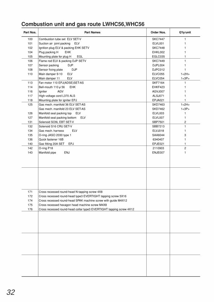
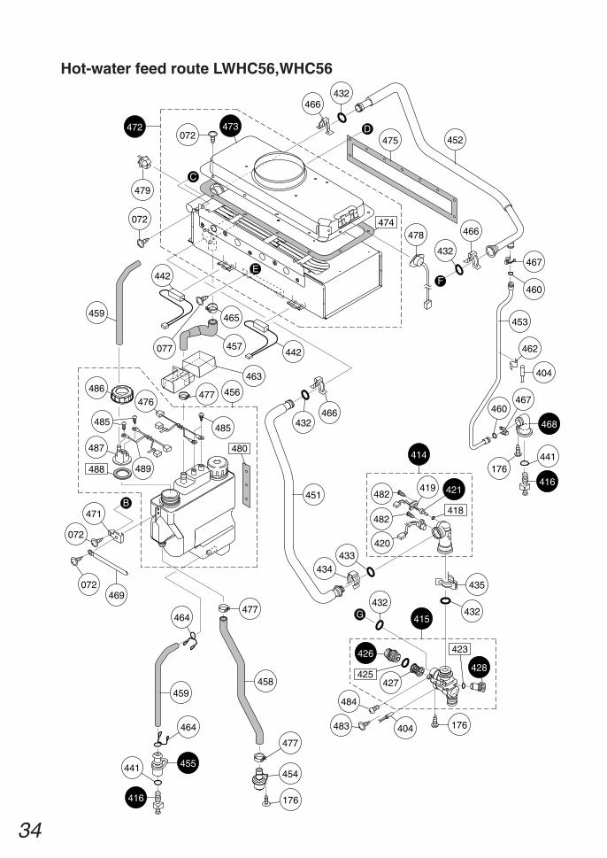
Hot-water feed route LWHC56,WHC56
HEAT EXCHANGERBegin winding up
(FRONT) (RIGHT SIDE)
FASTENER
(BACK)
THERMAL FUSE
(LEFT SIDE)
FASTENER
FASTENER
403
407
406
410
410411
408 171
418
424 419
481
417429
413
446
417
432
435412
432
435
445
431484
435
432
432435
418440
444
441
416
437
443
405
176
404483
G
F
E
410
D
077
461
442400
438
(Thermal fuse rounding procedure)
410
411403
400407
405461
34
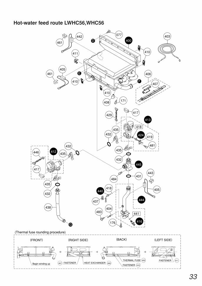
Hot-water feed route LWHC56,WHC56
427
426
425
423
428
484
176404483
415
435
432432
434433
482 421419
482
420
418
414
F
G
D
C
472
072
072473
474
466432
475 452
466
432
442
463
466
465
457
432
442
477
459
464
441
077
E
464
455
416
458
477
456
451
467
453
460
441
416
468
176
467460
462
404
478
477
479
B
072469
454
176
485
480
485
487
459
476
489
471
072
486
488
35
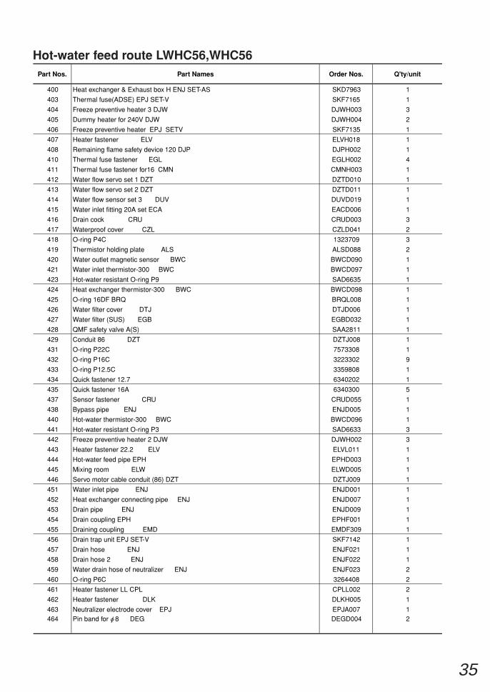
Hot-water feed route LWHC56,WHC56
400 Heat exchanger & Exhaust box H ENJ SET-AS SKD7963 1
403 Thermal fuse(ADSE) EPJ SET-V SKF7165 1
404 Freeze preventive heater 3 DJW DJWH003 3
405 Dummy heater for 240V DJW DJWH004 2
406 Freeze preventive heater EPJ SETV SKF7135 1
407 Heater fastener ELV ELVH018 1
408 Remaining flame safety device 120 DJP DJPH002 1
410 Thermal fuse fastener EGL EGLH002 4
411 Thermal fuse fastener for16 CMN CMNH003 1
412 Water flow servo set 1 DZT DZTD010 1
413 Water flow servo set 2 DZT DZTD011 1
414 Water flow sensor set 3 DUV DUVD019 1
415 Water inlet fitting 20A set ECA EACD006 1
416 Drain cock CRU CRUD003 3
417 Waterproof cover CZL CZLD041 2
418 O-ring P4C 1323709 3
419 Thermistor holding plate ALS ALSD088 2
420 Water outlet magnetic sensor BWC BWCD090 1
421 Water inlet thermistor-300 BWC BWCD097 1
423 Hot-water resistant O-ring P9 SAD6635 1
424 Heat exchanger thermistor-300 BWC BWCD098 1
425 O-ring 16DF BRQ BRQL008 1
426 Water filter cover DTJ DTJD006 1
427 Water filter (SUS) EGB EGBD032 1
428 QMF safety valve A(S) SAA2811 1
429 Conduit 86 DZT DZTJ008 1
431 O-ring P22C 7573308 1
432 O-ring P16C 3223302 9
433 O-ring P12.5C 3359808 1
434 Quick fastener 12.7 6340202 1
435 Quick fastener 16A 6340300 5
437 Sensor fastener CRU CRUD055 1
438 Bypass pipe ENJ ENJD005 1
440 Hot-water thermistor-300 BWC BWCD096 1
441 Hot-water resistant O-ring P3 SAD6633 3
442 Freeze preventive heater 2 DJW DJWH002 3
443 Heater fastener 22.2 ELV ELVL011 1
444 Hot-water feed pipe EPH EPHD003 1
445 Mixing room ELW ELWD005 1
446 Servo motor cable conduit (86) DZT DZTJ009 1
451 Water inlet pipe ENJ ENJD001 1
452 Heat exchanger connecting pipe ENJ ENJD007 1
453 Drain pipe ENJ ENJD009 1
454 Drain coupling EPH EPHF001 1
455 Draining coupling EMD EMDF309 1
456 Drain trap unit EPJ SET-V SKF7142 1
457 Drain hose ENJ ENJF021 1
458 Drain hose 2 ENJ ENJF022 1
459 Water drain hose of neutralizer ENJ ENJF023 2
460 O-ring P6C 3264408 2
461 Heater fastener LL CPL CPLL002 2
462 Heater fastener DLK DLKH005 1
463 Neutralizer electrode cover EPJ EPJA007 1464 Pin band for 8 DEG DEGD004 2
Part Nos. Part Names Order Nos. Q'ty/unit
36
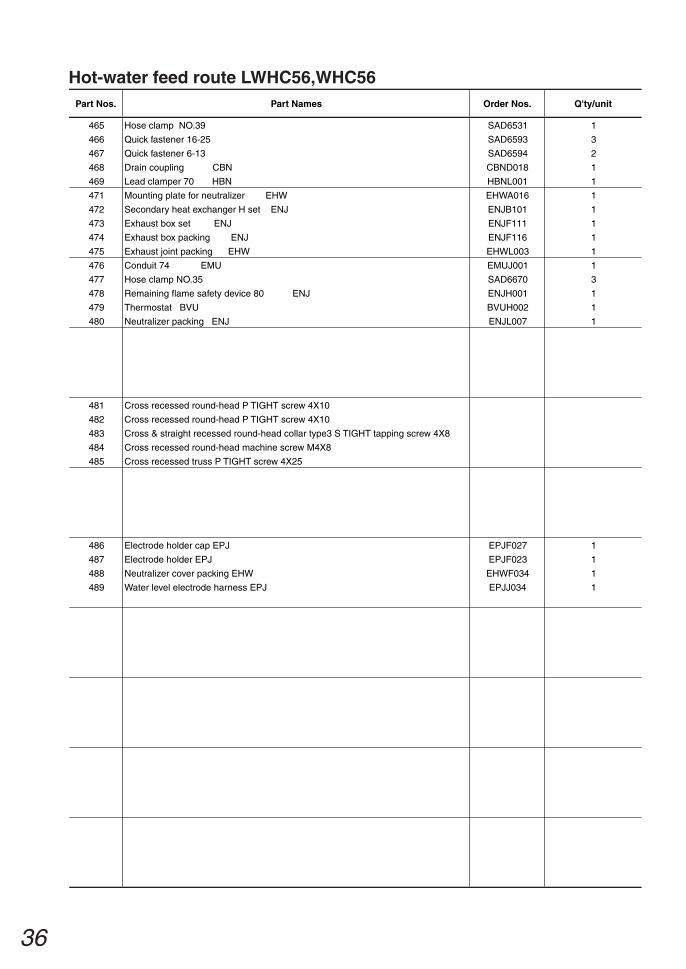
Hot-water feed route LWHC56,WHC56
465 Hose clamp NO.39 SAD6531 1
466 Quick fastener 16-25 SAD6593 3
467 Quick fastener 6-13 SAD6594 2
468 Drain coupling CBN CBND018 1
469 Lead clamper 70 HBN HBNL001 1
471 Mounting plate for neutralizer EHW EHWA016 1
472 Secondary heat exchanger H set ENJ ENJB101 1
473 Exhaust box set ENJ ENJF111 1
474 Exhaust box packing ENJ ENJF116 1
475 Exhaust joint packing EHW EHWL003 1
476 Conduit 74 EMU EMUJ001 1
477 Hose clamp NO.35 SAD6670 3
478 Remaining flame safety device 80 ENJ ENJH001 1
479 Thermostat BVU BVUH002 1
480 Neutralizer packing ENJ ENJL007 1
481 Cross recessed round-head P TIGHT screw 4X10
482 Cross recessed round-head P TIGHT screw 4X10
483 Cross & straight recessed round-head collar type3 S TIGHT tapping screw 4X8
484 Cross recessed round-head machine screw M4X8
485 Cross recessed truss P TIGHT screw 4X25
486 Electrode holder cap EPJ EPJF027 1
487 Electrode holder EPJ EPJF023 1
488 Neutralizer cover packing EHW EHWF034 1
489 Water level electrode harness EPJ EPJJ034 1
Part Nos. Part Names Order Nos. Q'ty/unit
37
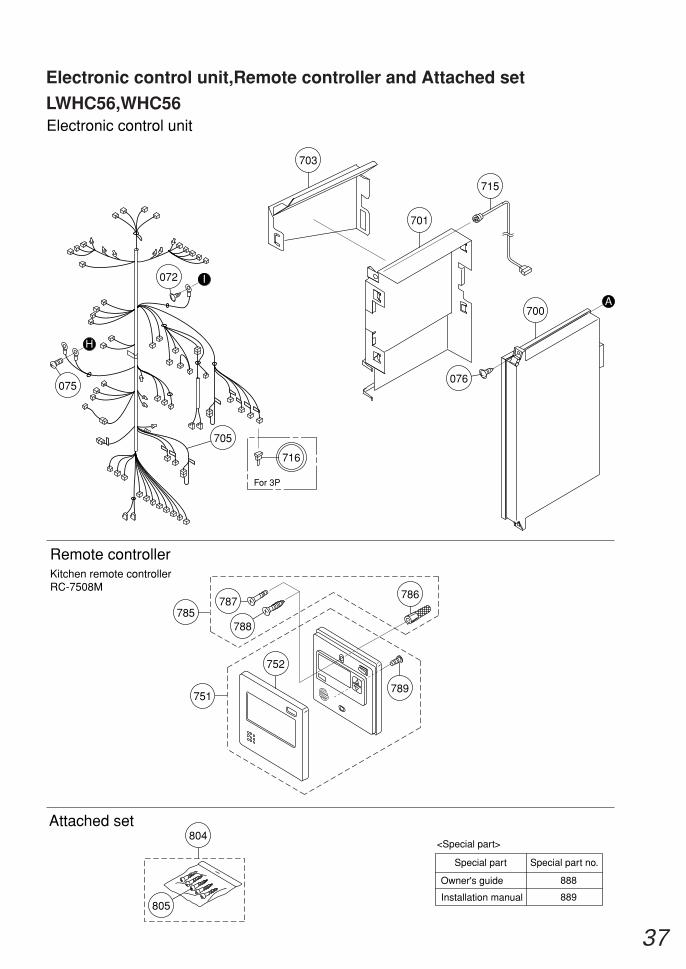
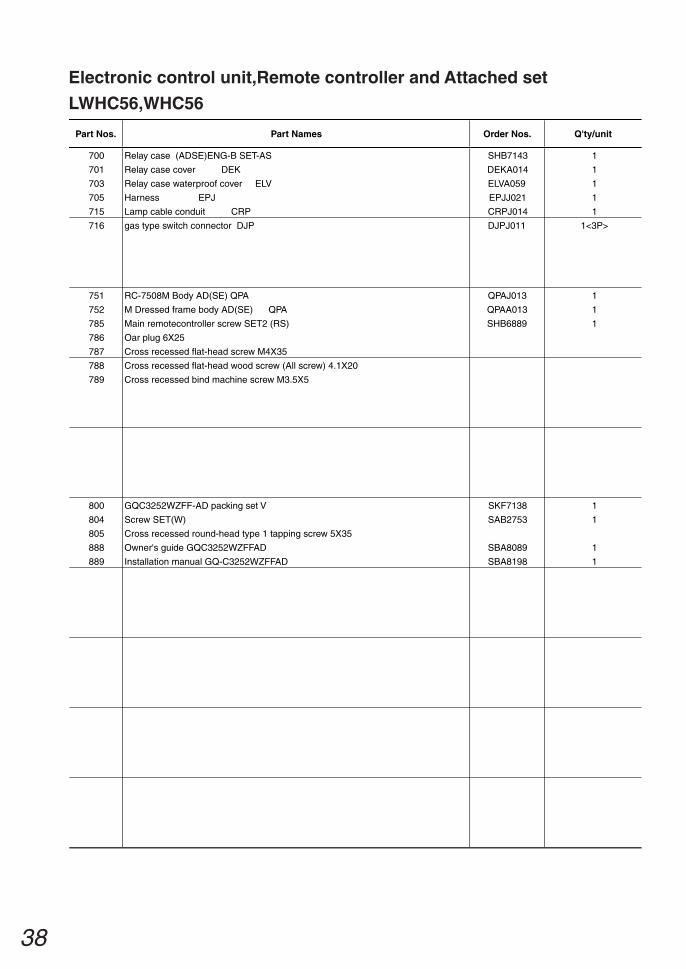
Electronic control unit,Remote controller and Attached set
LWHC56,WHC56
Remote controllerKitchen remote controllerRC-7508M
Special part Special part no.
<Special part>
Owner's guide 888
Installation manual 889
Electronic control unit
Attached set
700
701
715
705
076
A
703
805
H
075
751
752
786
788
787
072 I
789
785
804
716
For 3P
38
Electronic control unit,Remote controller and Attached set
LWHC56,WHC56
700 Relay case (ADSE)ENG-B SET-AS SHB7143
701 Relay case cover DEK DEKA014
703 Relay case waterproof cover ELV ELVA059
705 Harness EPJ EPJJ021
715 Lamp cable conduit CRP CRPJ014
751 RC-7508M Body AD(SE) QPA QPAJ013
752 M Dressed frame body AD(SE) QPA QPAA013
786
785
Oar plug 6X25
787 Cross recessed flat-head screw M4X35
788 Cross recessed flat-head wood screw (All screw) 4.1X20
789 Cross recessed bind machine screw M3.5X5
800 GQC3252WZFF-AD packing set V SKF7138
804 Screw SET(W) SAB2753
805 Cross recessed round-head type 1 tapping screw 5X35
888 Owner's guide GQC3252WZFFAD SBA8089
889 Installation manual GQ-C3252WZFFAD SBA8198
1
1
1
1
1
716 gas type switch connector DJP DJPJ011 1<3P>
1
1
Main remotecontroller screw SET2 (RS) SHB6889 1
1
1
1
1
Part Nos. Part Names Order Nos. Q'ty/unit
39
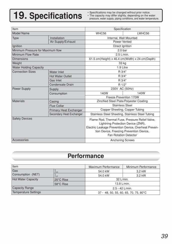
ItemGasConsumption (NET)
Hot Water Capacity
Capacity RangeTemperature Settings
12H
13P
25°C Rise
58°C Rise
32 L/min.13.8 L/min.
2.5 - 42 L/min.37 - 48, 50, 55, 60, 65, 70, 75, 80°C
Maximum Performance Minimum Performance
Specification
Internal, Wall MountedPower VentedDirect Ignition
2.0 bar2.5 L/min.
61.5 cm(Height) x 46.4 cm(Width) x 24 cm(Depth)33 kg
1.9 LitreR 3/4"
R 3/4"R 3/4"
R 1/2"230V AC (50Hz)
140W
Zincified Steel Plate/Polyester CoatingStainless Steel
Copper Sheeting, Copper Tubing
Flame Rod, Thermal Fuse, Pressure Relief Valve,Lightning Protection Device (ZNR),
Electric Leakage Prevention Device, Overheat Preven-tion Device, Freezing Prevention Device,
Fan Rotation Detector
Anchoring Screws
Performance
ItemModel Name
Type
IgnitionMinimum Pressure for Maximum flowMinimum Flow RateDimensionsWeightWater Holding Capacity
Accessories
InstallationAir Supply/Exhaust
Connection Sizes
Power Supply
Materials
Water InletHot Water OutletGas InletCondensate Drain
Supply
Consumption
CasingFlue Collar
Primary Heat ExchangerSecondary Heat Exchanger
Safety Devices
54.0 kW54.0 kW
3.2 kW3.2 kW
WHC56 LWHC56
140WFreeze Prevention 170W
Stainless Steel Sheeting, Stainless Steel Tubing
19. Specifications• Specifications may be changed without prior notice.• The capacity may differ slightly, depending on the water
pressure, water supply, piping conditions, and water temperature.
40
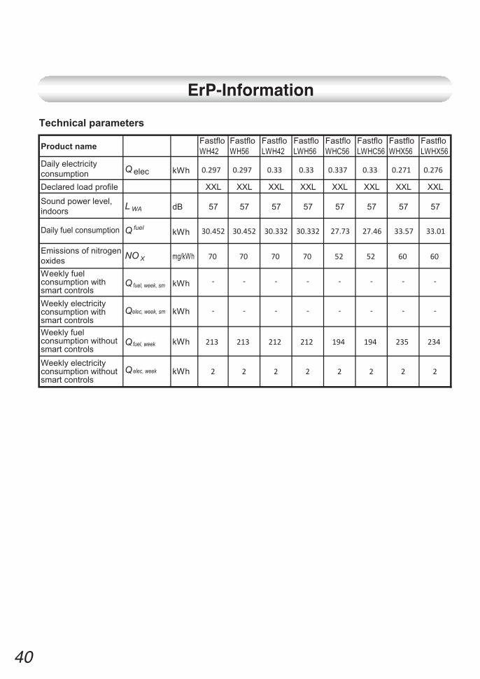
ErP-Information
Product name
Technical parameters Fastflo WH42
Fastflo WH56
Fastflo LWH42
Fastflo LWH56
Fastflo WHC56
Fastflo LWHC56
Fastflo WHX56
Fastflo LWHX56
Daily electricity consumption Q elec kWh 0.297 0.297 0.33 0.33 0.337 0.33 0.271 0.276
Declared load profile XXL XXL XXL XXL XXL XXL XXL XXL
Sound power level, indoors L WA dB 57 57 57 57 57 57 57 57
Daily fuel consumption Q fuel kWh 30.452 30.452 30.332 30.332 27.73 27.46 33.57 33.01
Emissions of nitrogen oxides NO X mg/kWh 70 70 70 70 52 52 60 60
Weekly fuel consumption with smart controls
Q fuel, week, sm kWh - - - - - - - -
Weekly electricity consumption with smart controls
Qelec, week, sm kWh - - - - - - - -
Weekly fuel consumption without smart controls
Qfuel, week kWh 213 213 212 212 194 194 235 234
Weekly electricity consumption without smart controls
Qelec, week kWh 2 2 2 2 2 2 2 2

Andrews. Built to perform.
CONDENSING GAS WATER HEATER | INSTALLATION AND SERVICE MANUAL
Customer support Monday - Friday 8am - 5pm
Tel 0345 070 1057Fax 0345 070 1059Email [email protected] andrewswaterheaters.co.ukTwitter @AndrewsWH
500403
Register now to activate your warranty www.andrewswaterheaters.co.uk/register-a-warranty. Please make sure you attach proof of purchase for your warranty to be monitored.
All descriptions and illustrations provided in this document have been carefully prepared but we reserve the right to make changes and improvements in our products which may affect the
Conditions of Sale which are available on request.
Aug 2016
ICOMEnergy Association
Related Documents