Condensate 750-330 03/2011 Return Systems Installation, Operation, and Maintenance

Welcome message from author
This document is posted to help you gain knowledge. Please leave a comment to let me know what you think about it! Share it to your friends and learn new things together.
Transcript

Condensate
750-33003/2011
Return SystemsInstallation, Operation,
and Maintenance

2
TO: Owners, Operators and/or Maintenance Personnel
This operating manual presents information that will help to properly operate and care for the equipment. Study its con-tents carefully. The unit will provide good service and continued operation if proper operating and maintenance instruc-tions are followed. No attempt should be made to operate the unit until the principles of operation and all of thecomponents are thoroughly understood. Failure to follow all applicable instructions and warnings may result in severepersonal injury or death.
It is the responsibility of the owner to train and advise not only his or her personnel, but the contractors' personnel whoare servicing, repairing or operating the equipment, in all safety aspects.
Cleaver-Brooks equipment is designed and engineered to give long life and excellent service on the job. The electricaland mechanical devices supplied as part of the unit were chosen because of their known ability to perform; however,proper operating techniques and maintenance procedures must be followed at all times. Although these components af-ford a high degree of protection and safety, operation of equipment is not to be considered free from all dangers andhazards inherent in handling and firing of fuel.
Any "automatic" features included in the design do not relieve the attendant of any responsibility. Such features merelyfree him of certain repetitive chores and give him more time to devote to the proper upkeep of equipment.
It is solely the operator’s responsibility to properly operate and maintain the equipment. No amount of written instructionscan replace intelligent thinking and reasoning and this manual is not intended to relieve the operating personnel of theresponsibility for proper operation. On the other hand, a thorough understanding of this manual is required before at-tempting to operate, maintain, service, or repair this equipment.
Because of state, local, or other applicable codes, there are a variety of electric controls and safety devices which varyconsiderably from one boiler to another. This manual contains information designed to show how a basic burner operates.
Operating controls will normally function for long periods of time and we have found that some operators become lax intheir daily or monthly testing, assuming that normal operation will continue indefinitely. Malfunctions of controls lead touneconomical operation and damage and, in most cases, these conditions can be traced directly to carelessness anddeficiencies in testing and maintenance.
It is recommended that a boiler room log or record be maintained. Recording of daily, weekly, monthly and yearly main-tenance activities and recording of any unusual operation will serve as a valuable guide to any necessary investigation.Most instances of major boiler damage are the result of operation with low water. We cannot emphasize too strongly theneed for the operator to periodically check his low water controls and to follow good maintenance and testing practices.Cross-connecting piping to low water devices must be internally inspected periodically to guard against any stoppageswhich could obstruct the free flow of water to the low water devices. Float bowls of these controls must be inspectedfrequently to check for the presence of foreign substances that would impede float ball movement.
The waterside condition of the pressure vessel is of extreme importance. Waterside surfaces should be inspected fre-quently to check for the presence of any mud, sludge, scale or corrosion.
It is essential to obtain the services of a qualified water treating company or a water consultant to recommend the properboiler water treating practices.
The operation of this equipment by the owner and his or her operating personnel must comply with all requirements orregulations of his insurance company and/or other authority having jurisdiction. In the event of any conflict or inconsis-tency between such requirements and the warnings or instructions contained herein, please contact Cleaver-Brooks be-fore proceeding.
DO NOT OPERATE, SERVICE, OR REPAIR THIS EQUIPMENT UNLESS YOU FULLY UNDERSTAND ALL APPLICABLE SECTIONS OF THIS MANUAL.
DO NOT ALLOW OTHERS TO OPERATE, SERVICE, OR REPAIR THIS EQUIPMENT UNLESS THEY FULLY UNDERSTAND ALL APPLICABLE SECTIONS OF THIS MANUAL.
FAILURE TO FOLLOW ALL APPLICABLE WARNINGS AND INSTRUCTIONS MAY RESULT IN SEVEREPERSONAL INJURY OR DEATH.
! DANGERWARNING

3
CONTENTSSection 1 — Installation, General Operation and Maintenance
INSTALLING THE UNIT . . . . . . . . . . . . . . . . . . . . . . . . . . 1-3WIRING . . . . . . . . . . . . . . . . . . . . . . . . . . . . . . . . . . . . . 1-4OPERATING THE UNIT . . . . . . . . . . . . . . . . . . . . . . . . . . 1-4MAINTENANCE. . . . . . . . . . . . . . . . . . . . . . . . . . . . . . . . 1-4
Section 2 — PumpsPRE-INSTALLATION CHECKLIST . . . . . . . . . . . . . . . . . . . . . . 2-3ELECTRICAL REQUIREMENTS . . . . . . . . . . . . . . . . . . . . . . . 2-4MOTOR PROTECTION . . . . . . . . . . . . . . . . . . . . . . . . . . . . 2-4INSTALLATION PROCEDURES . . . . . . . . . . . . . . . . . . . . . . . 2-5INITIAL STARTUP . . . . . . . . . . . . . . . . . . . . . . . . . . . . . . . 2-7MAINTENANCE . . . . . . . . . . . . . . . . . . . . . . . . . . . . . . . . 2-8TROUBLESHOOTING . . . . . . . . . . . . . . . . . . . . . . . . . . . . 2-11MOTOR SPECIFICATIONS . . . . . . . . . . . . . . . . . . . . . . . . . 2-14
APPENDIX A — Float Switch . . . . . . . . . . . . . . . . . . . . . . . . . . . . . . . . . . . . . A1APPENDIX B — Level Control . . . . . . . . . . . . . . . . . . . . . . . . . . . . . . . . . . . . .B1

4

www.cleaverbrooks.com
Section 1 - Installation, General Operation and Maintenance
INSTALLING THE UNIT. . . . . . . . . . . . . . . . . . . . . . . . . . . . . . . . . . 1-3Location. . . . . . . . . . . . . . . . . . . . . . . . . . . . . . . . . . . . . . . . . . . 1-3Return Piping . . . . . . . . . . . . . . . . . . . . . . . . . . . . . . . . . . . . . . 1-3Discharge Piping . . . . . . . . . . . . . . . . . . . . . . . . . . . . . . . . . . . . 1-3Water Level Gauge (Optional) . . . . . . . . . . . . . . . . . . . . . . . . . . . 1-3Vent . . . . . . . . . . . . . . . . . . . . . . . . . . . . . . . . . . . . . . . . . . . . . 1-3Overflow . . . . . . . . . . . . . . . . . . . . . . . . . . . . . . . . . . . . . . . . . . 1-3Drain . . . . . . . . . . . . . . . . . . . . . . . . . . . . . . . . . . . . . . . . . . . . 1-3
WIRING . . . . . . . . . . . . . . . . . . . . . . . . . . . . . . . . . . . . . . . . . . . . 1-4OPERATING THE UNIT . . . . . . . . . . . . . . . . . . . . . . . . . . . . . . . . . 1-4
Before Starting Unit . . . . . . . . . . . . . . . . . . . . . . . . . . . . . . . . . . . 1-4Starting . . . . . . . . . . . . . . . . . . . . . . . . . . . . . . . . . . . . . . . . . . . 1-4
MAINTENANCE . . . . . . . . . . . . . . . . . . . . . . . . . . . . . . . . . . . . . . 1-4Pump . . . . . . . . . . . . . . . . . . . . . . . . . . . . . . . . . . . . . . . . . . . . 1-4Motor . . . . . . . . . . . . . . . . . . . . . . . . . . . . . . . . . . . . . . . . . . . . 1-5Inlet Strainer . . . . . . . . . . . . . . . . . . . . . . . . . . . . . . . . . . . . . . . 1-5Ordering Repair Parts . . . . . . . . . . . . . . . . . . . . . . . . . . . . . . . . . 1-5
Condensate Return Systems Installation, Operation, and Maintenance
1-2 Part No. 750-330
! Caution
Waterside care is of prime importance. For specific information or assistance with your water treatmentrequirements, contact your Cleaver-Brooks service and parts representative. Failure to follow theseinstructions could result in equipment damage
! Caution
Inspection and maintenance should be per formed only by trained personnel who are familiar with thisequipment. Failure to follow these instructions could result in equipment damage
! Warning
When replacing a control, be sure to lock out the main power supply switch since the control is “hot”.Failure to follow these instructions could result in serious personal injury or death.
! Warning
Disconnect and lock out electrical power to the equipment before performing any maintenance or servicework. Failure to follow these instructions can result in electrical shock and serious personal injury ordeath.
Installation, Operation, and Maintenance Condensate Return Systems
Part No. 750-330 1-3
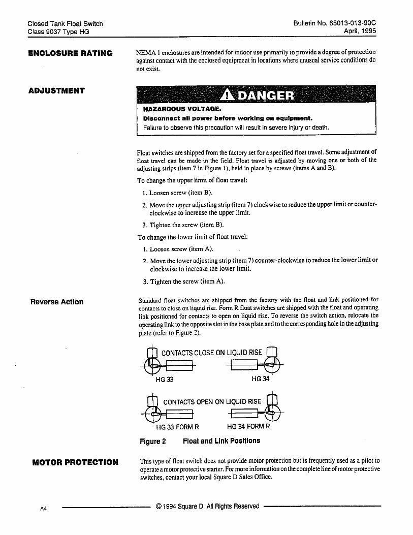
A. INSTALLING THE UNIT
1. LocationInstall the unit in a clean, dry, ventilated, location which is accessible for inspection and care. The receiverinlet should be low enough to permit all return lines to empty by gravity to the receiver. No specialfoundation is necessary for the un it, although the floor or other sur face upon which it is t o be installedshould be structurally sound and relatively smooth and level.
2. Return PipingConnect the return line to the receiver tank with a gate valve, st rainer, and union installed in the line asclose as possible to the tank. The union should be nearest to the tank.
3. Discharge PipingConnect the discharge piping from the pump discharge connection. A union, pressure gauge, swing checkvalve, gate valve and flexible connector - in t hat order - should be installed in the discharge piping, withthe union nearest to the pump. If the discharge piping is longer than 50 feet, the pipe diameter should beone or two sizes larger than the pump discharge. Al l piping should be properly supported independent ofthe receiver or pump so as to prevent strain on the unit. Do not force pipes or fittings into place. Pipe strainon the pump causes misalignment in the coupling, which is harmful to the coupling and bearings and caneventually cause their failure.
4. Water Level Gauge (Optional)Water level gauges which are mounted on the tank before shipping should be checked to be sure the glassis in good conditi on and to be sur e the drain petcock in the bottom fitting is closed. Gauges shippedseparately should be mounted on the tank after the makeup valve is connected to reduce the possibility ofdamaging the gauges while working on the valve. Screw the fittings into the end of the tank in the 1/2” pipeconnections provided, making sure the fitting with the drain petcock is in the lower position. Remove thecompression nut, brass washer, and rubber sleeve from each fitting. Slide each piece onto both ends of theglass in the same order so that at least one inch of the glass sticks out. Then set one end of the glass inplace in one of the fittings and carefully fit the other end into the other fitting. Center the glass verticallybetween the bottoms of the fittings and tighten compression nuts to a snug fit. After the tank is filled, itmay be necessary to retighten the compression nuts if the tank leaks. Be sure the petcock is closed. Putthe guard rods in place on each side of the glass.
5. VentInstall the vent pipe in the openings on the top of the receiver. Pipe the vent to a safe point of discharge.
6. OverflowAn overflow pipe should be installed in the top opening in the end of the receiver, or in one of the openingsin the top of the receiver, and extended to a suitable drain.
7. DrainA gate valve should be installed in the bottom of the receiver and should be piped to a suitable drain.

Condensate Return Systems Installation, Operation, and Maintenance
1-4 Part No. 750-330
B. WIRINGAll wiring should be done in accordance with local code or power company regulations. All units should bewired with a safety switch installed so the entire circuit can be shut off from motor, starter, and/or any otherelectrical controls or devices which may be installed as part of the unit.
Refer to the appropriate wiring diagram furnished by your local authorized Cleaver-Brooks Representativeto assist in connecting electric service to the unit.
C. OPERATING THE UNIT
1. Before Starting Unita.Be sure the pump rotates freely when turned by hand.b.Check the motor nameplate data to be sure voltage and cycle correspond to electric current connected to unit.c.Be sure the pump control float is released from shipping position.d.Before placing the unit into regular service, it is advisable to start it without load to determine that the wir-ing is correct.e.The check valve in the discharge line must be installed in the proper position to open when pump is in operation. All gate valves in return and discharge lines must be fully opened.f.The gate valve in the return line must be open.g.Set the circuit breaker or disconnect switch to the "on" position.
2. Startinga.Refer to Coolant Pump Section
i.Air Eliminationii.Check the Direction of Rotationiii.Starting and Adjusting
b.Check the pressure gauge to see if the pump is operating. Make sure the pressure is set to the appropriate discharge pressure.c.Check the temperature of the water being pumped. If it is higher than the temperature for which the unit was sold, it might cause a reduction of capacity or it might even stop pumping. If in doubt, consult your dealer or the representative in your area.d.After the unit has run for some time, check to see that the motor bearings are not overheating. If in doubt as to safe operating temperature, take the temperature of the motor and surrounding air and consult with the local sales office or service station of the motor manufacturer.
D.MAINTENANCECleaver-Brooks Condensate Return Tanks are designed to give long, trouble free service, if installed andoperated under suitable conditions and given proper care. However, in time, it may be come necessary toservice or replace certain parts of the unit to maintain its peak performance. In this event, the followingprocedures should be followed.
1. PumpRefer to the pump instruction sheets for complete maintenance instructions.
Installation, Operation, and Maintenance Condensate Return Systems
Part No. 750-330 1-5
If it becomes necessary to remove the pump:1.Break the electrical circuit to the unit by setting the circuit breaker or disconnect switch in the “off” posi-tion.2.Close the gate valve in the return and discharge piping to avoid flooding the receiver or floor while the pump is out of service.3.Disconnect union in discharge piping.
2. MotorThe only maintenance required by the motor is periodic lubrication, which should be done in accordance with the motor manufacturer's instructions. If repairs are needed, refer to the nearest authorized service sta-tion or the motor.
To remove the motor from the unit:
1.Disconnect and lock out the electrical circuit to the unit by setting the circuit breaker or disconnect switch in "off" position; then disconnect all wire connections from the motor manufacturer.2.Remove the coupling guard screens.3.Using the proper metric Allen wrench, loosen the four cap screws in the coupling.4.With the correct size wrench, loosen and remove the four bolts which hold the motor to the discharge sec-tion of the pump end.5.Lift the motor straight up until the shaft is free from the coupling.
3. Inlet StrainerIf the boiler water is maintained in proper condition, the strainer will require little if any maintenance. How-ever, it should be inspected occasionally to be sure the screen is not plugged up with scale or other foreign material. Depending on the individual installation, it may be necessary to clean the strainer screen every month, or only once or twice per year. After a few times, experience will indicate how often it should be cleaned.
To remove the screen for inspection or cleaning:
1.Close the gate valves in the return piping.2.Remove the drain plug in the bottom cover of the strainer.3.Remove the cap screws holding the cover on the strainer and take off the cover and gasket.4.Carefully pull out the screen. Thoroughly clean the screen or replace with a new one if the old one cannotbe used. Reassemble the parts and tighten the cap screws evenly for a leak-proof seal.
4. Ordering Repair PartsFurnish complete information when ordering par ts; include the unit number of the packaged feed systemas found on the name plate. State the Cleaver -Brooks part number and the name and description of thepart required. Also state the quantity desired and specify method of shipment. Indicate date the materialis required. If parts are required such as electric motors, etc., be sure to give the complete name plate datafrom the accessory for which the parts are required.
Repair or replacement parts should be ordered from your Cleaver-Brooks representative.

Condensate Return Systems Installation, Operation, and Maintenance
1-6 Part No. 750-330

www.cleaverbrooks.com
Section 2 - PumpsPRE-INSTALLATION CHECKLIST . . . . . . . . . . . . . . . . . . . . . . . . . . . . . . . 2-2
Confirm you have the right pump . . . . . . . . . . . . . . . . . . . . . . . . . . . 2-2Check the condition of the pump . . . . . . . . . . . . . . . . . . . . . . . . . . . 2-3
ELECTRICAL REQUIREMENTS. . . . . . . . . . . . . . . . . . . . . . . . . . . . . . . . . 2-3Supply power . . . . . . . . . . . . . . . . . . . . . . . . . . . . . . . . . . . . . . . . . 2-3Field wiring . . . . . . . . . . . . . . . . . . . . . . . . . . . . . . . . . . . . . . . . . . 2-3
MOTOR PROTECTION . . . . . . . . . . . . . . . . . . . . . . . . . . . . . . . . . . . . . . . 2-3Single-Phase Motors . . . . . . . . . . . . . . . . . . . . . . . . . . . . . . . . . . . . 2-3Three-Phase Motors . . . . . . . . . . . . . . . . . . . . . . . . . . . . . . . . . . . . 2-3
INSTALLATION PROCEDURES . . . . . . . . . . . . . . . . . . . . . . . . . . . . . . . . 2-4Pump location . . . . . . . . . . . . . . . . . . . . . . . . . . . . . . . . . . . . . . . . 2-4Piping . . . . . . . . . . . . . . . . . . . . . . . . . . . . . . . . . . . . . . . . . . . . . . 2-4Suction conditions . . . . . . . . . . . . . . . . . . . . . . . . . . . . . . . . . . . . . 2-4Bypass . . . . . . . . . . . . . . . . . . . . . . . . . . . . . . . . . . . . . . . . . . . . . 2-5Position of terminal box . . . . . . . . . . . . . . . . . . . . . . . . . . . . . . . . . . 2-6
INITIAL STARTUP . . . . . . . . . . . . . . . . . . . . . . . . . . . . . . . . . . . . . . . . . . 2-6Air elimination . . . . . . . . . . . . . . . . . . . . . . . . . . . . . . . . . . . . . . . . 2-6Check the direction of rotation . . . . . . . . . . . . . . . . . . . . . . . . . . . . . 2-6Starting and adjusting . . . . . . . . . . . . . . . . . . . . . . . . . . . . . . . . . . . 2-6
MAINTENANCE . . . . . . . . . . . . . . . . . . . . . . . . . . . . . . . . . . . . . . . . . . . 2-7Motor lubrication . . . . . . . . . . . . . . . . . . . . . . . . . . . . . . . . . . . . . . 2-7Periodic safety checks . . . . . . . . . . . . . . . . . . . . . . . . . . . . . . . . . . . 2-8Replacing the motor . . . . . . . . . . . . . . . . . . . . . . . . . . . . . . . . . . . . 2-8
TROUBLESHOOTING . . . . . . . . . . . . . . . . . . . . . . . . . . . . . . . . . . . . . . 2-10Troubleshooting table . . . . . . . . . . . . . . . . . . . . . . . . . . . . . . . . . . 2-10Electrical measurements . . . . . . . . . . . . . . . . . . . . . . . . . . . . . . . . 2-11
MOTOR SPECIFICATIONS . . . . . . . . . . . . . . . . . . . . . . . . . . . . . . . . . . . 2-13
Condensate Return Systems Pumps
2-2 Part No. 750-330
All electrical work should be performed by a qualified electrician in accordance with the latest edition of the National Electrical Code, local codes and regulations.
! WarningA faulty motor or wiring can cause electrical shock that could be fatal, whether touched directly or conducted through standing water. For this reason, proper grounding of the motor frame to the power supply's grounding terminal is required for safe installation and operation.In all installations, the above-ground metal plumbing should be connected to the power supply ground as described in Article 250-80 of the National Electrical Code.
! WarningThe safe operation of this pump requires that it be grounded in accordance with the National Electrical Code and local governing codes or regulations. Connect the ground wire to the grounding screw in the terminal box and then to the acceptable grounding point.
Pumps Condensate Return Systems
Part No. 750-330 2-3
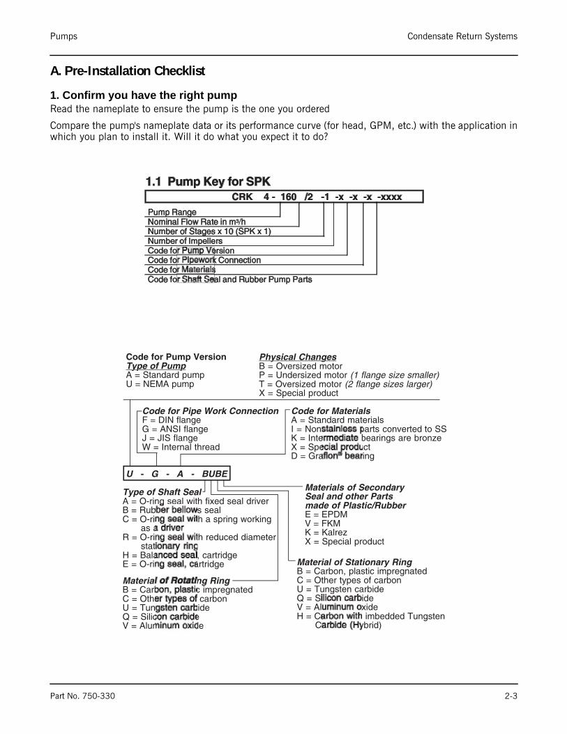
A. Pre-Installation Checklist
1. Confirm you have the right pumpRead the nameplate to ensure the pump is the one you ordered
Compare the pump's nameplate data or its performance curve (for head, GPM, etc.) with the application inwhich you plan to install it. Will it do what you expect it to do?
Condensate Return Systems Pumps
2-4 Part No. 750-330
2. Check the condition of the pumpThe shipping carton your pump came in is specially designed around your pump during production toprevent damage. As a precaution, it should remain in the car ton until you are ready to install it. At thatpoint, look at the pump and examine it for any damage that may have occurred during shipping. Examineany other parts of the shipment as well (electrical control boxes, etc) for any visible damage. If you find any,contact the transportation company in writing and ask to have it inspected.
B. Electrical Requirements
1. Supply powerThe incoming electrical supply should be verified so the voltage, phase and frequency match that of thepump motor. The proper operating voltage and other electrical information can be fo und on the motornameplate. These motors are designed to run on ± 10% of the nameplate rated voltage. For dual-voltagemotors, the motor should be
internally connected to operate on the voltage closest to the 10% rating, i.e., a 208 voltage motor wiredper the 208 volt connection diagram. Wiring connection diagrams can be found on the plates attached tothe motor.
If voltage variations are larger than ±10%, do not operate the pump.
2. Field wiringWire sizes should be based on the current carrying properties of a conductor as required by the latest editionof the National Electrical Code or local regulations. Direct on line (D.O.L.) starting is approved due to theextremely fast run-up time of the motor and the low moment of inertia of pump and motor. If D.O.L. startingis not acceptable and reduced starting current is required, an auto transformer or resistant starter shouldbe used. It is suggested that a fused disconnect be used for each pump where service and standby pumpsare installed.
C. Motor Protection
1. Single-Phase MotorsWith the exception of 7-1/2 and 10 HP motors (which require external protection) single- phaseSPK pumps are equipped with multi-voltage, squirrel-cage induction motors with built-in thermalprotection.
2. Three-Phase MotorsSPK Pumps with three-phase motors must be used with the proper size and type of motor-starter to ensurethe motor is protected against damage from low voltage, phase failure, current imbalance and overloads.
A properly sized starter with manual reset and ambient compensated extra quick trip in all three legs shouldbe used. The overload should be sized and adjusted to the full-load current rating of the motor. Under nocircumstances should the overloads be set to a higher value than the full load current shown on the motornameplate. This will void the warranty.
Overloads for auto trans formers and resistant starters should be sized in accordance with therecommendations of the manufacturer.
Pumps Condensate Return Systems
Part No. 750-330 2-5
D. Installation Procedures
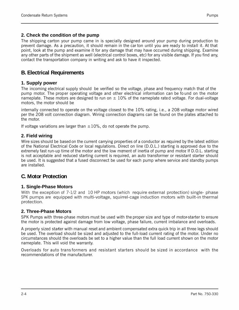
1. Pump locationSPK pumps are designed for tank-mounting and may be installed in ei ther a vertical or horizontalorientation. Where the unit is to be installed so as to position its mounting flange below the liquid level orin a pressurized tank, a gasket must be fitted between the pump's mounting flange and tank.
2. PipingThe discharge ports of SPK pump units which are supplied for use with NEMA motors have 1-1/4 inchfemale NPT threads. Other discharge pipe sizes must be accommodated via the use of appropriate adapterbushings.
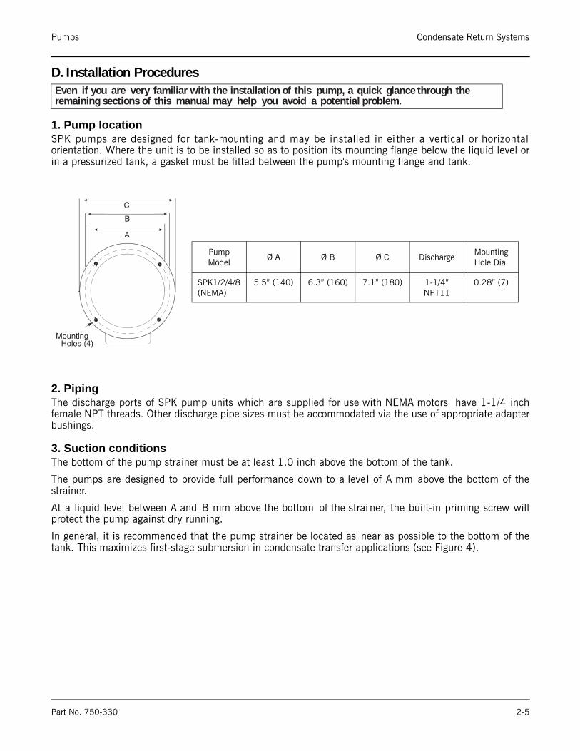
3. Suction conditionsThe bottom of the pump strainer must be at least 1.0 inch above the bottom of the tank.
The pumps are designed to provide full performance down to a level of A mm above the bottom of thestrainer.
At a liquid level between A and B mm above the bottom of the strai ner, the built-in priming screw willprotect the pump against dry running.
In general, it is recommended that the pump strainer be located as near as possible to the bottom of thetank. This maximizes first-stage submersion in condensate transfer applications (see Figure 4).
Even if you are very familiar with the installation of this pump, a quick glance through the remaining sections of this manual may help you avoid a potential problem.
Pump Model
Ø A Ø B Ø C DischargeMounting Hole Dia.
SPK1/2/4/8 (NEMA)
5.5” (140) 6.3” (160) 7.1” (180) 1-1/4” NPT11
0.28” (7)
Condensate Return Systems Pumps
2-6 Part No. 750-330
4. BypassA bypass line or pressure relief valve should be installed in the discharge pipe if there is any possibility thepump may operate against a closed valve in the discha rge line (or in any othe r no flow condition). Flowthrough the pump is required to ensure adequate cooling and lubrication of the pump is maintained.
The following table shows minimum flow rates:
Pump Type Minimum Flow RateSPK1 1.0 GPMSPK2 1.2 GPMSPK4 3.0 GPMSPK8 5.3 GPM
-
Pumps Condensate Return Systems
Part No. 750-330 2-7
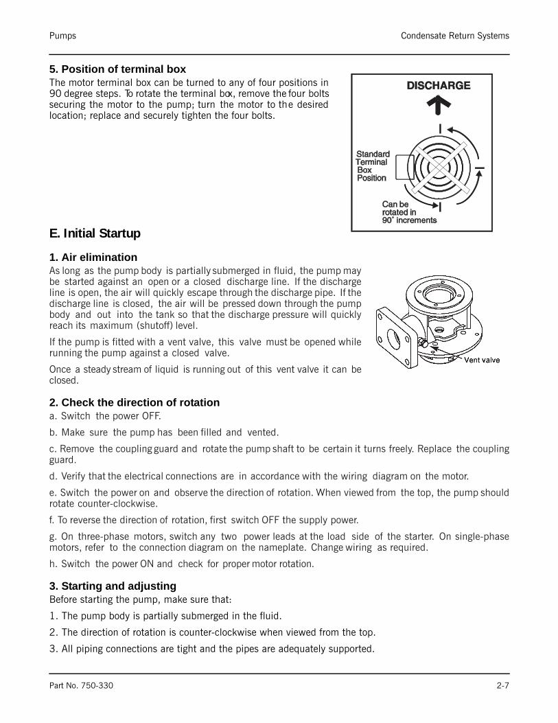
5. Position of terminal boxThe motor terminal box can be turned to any of four positions in90 degree steps. To rotate the terminal box, remove the four boltssecuring the motor to the pump; turn the motor to the desiredlocation; replace and securely tighten the four bolts.
E. Initial Startup
1. Air eliminationAs long as the pump body is partially submerged in fluid, the pump maybe started against an open or a closed discharge line. If the dischargeline is open, the air will quickly escape through the discharge pipe. If thedischarge line is closed, the air will be pressed down through the pumpbody and out into the tank so that the discharge pressure will quicklyreach its maximum (shutoff) level.
If the pump is fitted with a vent valve, this valve must be opened whilerunning the pump against a closed valve.
Once a steady stream of liquid is running out of this vent valve it can beclosed.
2. Check the direction of rotationa. Switch the power OFF.
b. Make sure the pump has been filled and vented.
c. Remove the coupling guard and rotate the pump shaft to be certain it turns freely. Replace the couplingguard.
d. Verify that the electrical connections are in accordance with the wiring diagram on the motor.
e. Switch the power on and observe the direction of rotation. When viewed from the top, the pump shouldrotate counter-clockwise.
f. To reverse the direction of rotation, first switch OFF the supply power.
g. On three-phase motors, switch any two power leads at the load side of the starter. On single-phasemotors, refer to the connection diagram on the nameplate. Change wiring as required.
h. Switch the power ON and check for proper motor rotation.
3. Starting and adjustingBefore starting the pump, make sure that:
1. The pump body is partially submerged in the fluid.
2. The direction of rotation is counter-clockwise when viewed from the top.
3. All piping connections are tight and the pipes are adequately supported.
Condensate Return Systems Pumps
2-8 Part No. 750-330
4. The pump inlet screen is clean and unblocked.
5. Depending on the application, it may be necessary to start the pump against a closed discharge valve inorder to prevent system damage due to wa ter hammer. If so, this valve should b e opened in a gradualmanner after the pump is started. Unless used as a flow throttling device, make sure this valve is completelyopened.
6. Check and record the voltage and amperage of the motor. Adjust the motor overloads if required.
7. Check and record operating pressures if pressure gauges have been installed.
8. Check all controls for proper operation. If pump is controlled by a pressure switch, check and adjust thecut-in and cut-out pressures. If low-water-level controls are used be sure the lo w-level switch is properlyadjusted so the pump cannot run if the pump should break suction
Pump cycling should be checked to ensure the pump is not starting more than:
20 times per hour on 1/2 to 5 HP models
15 times per hour on 7 1/2 to 15 HP models
10 times per hour on 20 to 40 HP models
Rapid cycling is a major ca use of premature motor fail ure due to increased heat buildup in the motor . Ifnecessary, adjust controls to reduce the frequency of starts and stops.
F. MaintenanceSPK multi-stage centrifugal pumps in stalled in accordance with these instructions and sized for correctperformance will operate efficiently and provide years of service.
The pumps are water-lubricated and do not require any external lubrication or inspection. The motors willrequire periodic lubrication as noted in the following paragraphs
1. Motor lubricationElectric motors are pre-lubricated at the factory and do not require additional lubrication at start-up. Motorscontaining sealed bearings do not require additional lubrication during the first 15,000 hours of operation.Motors with grease fittings should only be lubricated with lithium based grease.
Lubrication schedule: see tables below
! CautionUnder no circumstances should the pump be operated for any prolongedperiods of time without flow through the pump.
This can result in motor and pump damage due to overheating. A properlysized relief valve should be installed to allow sufficient water to circulatethrough the pump to provide adequate cooling and lubrication of the pumpbearings and seals.

Pumps Condensate Return Systems
Part No. 750-330 2-9
Do not over grease the bearings. Over greasing will cause increased bearing heat and can result in bearing/motor failure.
2. Periodic safety checksAt regular intervals depending on the conditions and time of operation, the following
checks should be made:
1. Pump meets required performance and is operating smoothly and quietly.
2. There are no leaks, particularly at the shaft seal.
3. The motor is not overheating.
4. Remove and clean all strainers or filters in the system.
5. Verify the tripping of the motor overload protection.
6. Check the operating of all controls. Check unit control cycling twice and adjust if necessary.
7. If the pump is not operated for unusually long periods, the unit should be maintained in accordance withthese instructions. In addition, if the pump is not drained, the pump shaft should be manually rotated orrun for short periods of time at monthly intervals.
If the pump fails to operate or there is a loss of performance, refer to the Troubleshooting section.
3. Replacing the motorIf the motor is damaged due to bearing failure, burning or electrical failure, the following instructions detailhow to remove the motor for replacement. It must be emphasized that motors used on SPK pumps arespecially selected to our rigid specifications. Replacement motors must be of the same frame size.
Severity of Service Ambient Temperature (Maximum)
Atmospheric contami-nation
Approved Types of Grease
Standard 104 ° (40 °C) Clean, little corrosion Shell Dolium, Chev-ron SRI#2 or compati-ble equivalent type of grease
Severe 122 ° (50° C) Moderate dirt, corro-sion
Extreme > 122 ° (50° C) or Class H insulation
Severe dirt, abrasive dust, corrosion
NEMA (IEC) Frame Size
Standard Service Interval
Severe Service Interval
Extreme Service Interval
Weight of grease to add oz. (grams)
Volume of grease to add in3 (teaspoons)
Up through 210 (132)
5500 hrs. 2750 hrs. 550 hrs. 0.30 (8.4) 0.6 (2)
Over 210 through 280 (180)
3600 hrs. 1800 hrs. 360 hrs. 0.61 (17.4) 1.2 (3.9)
Over 280 up through 360 (225)
2200 hrs. 1100 hrs 220 hrs. 0.81 (23.1) 1.5 (5.2)
Over 360 (225) 2200 hrs. 1100 hrs. 220 hrs. 2.12 (60.0) 4.1 (13.4)

Condensate Return Systems Pumps
2-10 Part No. 750-330
Removing the old motor
1. Remove the coupling guard screens.
2. Using the proper metric Allen wrench, loosen the four cap screws in the coupling.
3. With the correct size wrench, loosen and remove the four bolts which hold the motor to thedischarge section of the pump end.
4. Lift the motor straight up until the shaft is free from the coupling.
Installing the new motor
1. Thoroughly clean the surfaces of the motor and pump end mounting flanges. Set the
motor on the pump end.
2. Place the terminal box in the desired position by rotating the motor.
3. Insert the mounting bolts, and then tighten diagonally and evenly.
4. Using a larger screwdriver, raise the pump shaft by placing the tip of the screwdriver under the couplingand carefully elevating the coupling to its highest point.
Note: The shaft can only be raised approximately 0.20 inches (5 mm).
5. Now lower the shaft halfway back down the distance you just raised it (approximately the thickness ofa dime), and retighten the metric cap screws in the coupling. Be sure to tighten the top and bottom screwson one side of the coupling and then the other. Torque the coupling screws to the following specifications.
6. Check to see that the gaps between the coupling halves are equal. Loosen and re-adjust if necessary.
7. Be certain the pump shaft can be rotated by hand. If the shaft cannot be rotated or it binds, disassembleand check for misalignment.
8. Replace the two coupling guard screens.
Coupling bolt size Minimum Torque specifications
M6 10 ft-lbs
M8 23 ft-lbs
M10 46 ft-lbs

Pumps Condensate Return Systems
Part No. 750-330 2-11
G.Troubleshooting
1. Troubleshooting table
Pump Troubleshooting
PROBLEM POSSIBLE CAUSE CHECK REMEDY
Pump does not run
No power at pump panel Check for voltage at panel If no voltage at pump panel, check feeder panel for tripped circuits
Fuses are blown or circuit breakers are tripped
Turn off power and remove fuses. Check for continuity with ohmmeter
Replace blown fuses or reset circuit breaker. If new fuses blow or circuit breaker trips, the electrical installation, motor and wires must be checked.
Motor starter overloads are burned or have tripped out
Check for voltage on line and load side of starter
Replace burned heaters or reset. Inspect starter for other damage. If heater trips again, check the supply voltage and starter holding coil.
Starter does not energize Energize control circuit and check for voltage at the holding coil
If no voltage, check control circuit fuses. If voltage, check holding coil for shorts. Replace bad coil
Defective controls Check all safety and pressure switches for operation. Inspect contacts in control devices
Replace worn or defective parts or controls
Motor is defective Turn off power and disconnect wiring. Measure the lead to lead resistances with ohmmeter (RX-1). Measure lead to ground values with ohmmeter (RX- 100K). Record measured values
If an open or grounded winding is found, remove motor and repair or replace
Defective capacitor. (Single- phase motors)
Turn off power and discharge capacitor. Check with ohmmeter (RX-100K).
When the meter is connected to the capacitor, the needle should jump towards 0 ohms and slowly drift back to infinity. Replace if defective
Pump is bound Turn off power and manually rotate pump shaft
If shaft does not rotate easily, check coupling setting and adjust as necessary. If shaft rotation is still tight, remove pump and inspect. Disassemble and repair.
Pump runs but at reduced capacity or does not deliver water
Wrong rotation Check wiring for proper connections Correct wiring.
Pump body not partially submerged Turn pump off, close isolation valve(s). Check fluid level
Provide submergence by increasing fluid level in tank or sump; alternatively by repositioning pump at lower level
Strainers, inlet screen or valves are clogged
Remove strainer, screen or valve and inspect
Clean and replace strainer, screen and/or valves
Entrained air Check tank conditions for cascading fluid or vortexing
Install baffle(s) in tank. Relocate inlet pipe. Decrease pump flow rate
Fluid cavitating Compare pump NPSH requirements to available NPSH at pump flow rate
Decrease pump flow rate and/or fluid temperature. Increase first-stage submersion
Pump worn Install pressure gauge, start pump, gradually close the discharge valve and read pressure at shutoff
Convert measured pressure (in PSI) to head (in feet): (Measured PSI x 2.31 ft/PSI =_____ft.) Refer to the specific pump curve for shutoff head for that pump model. If head is close to curve, pump is probably OK. If not, remove pump and inspect
Pump impeller or guide vane is clogged
Disassemble and inspect pump passageways
Remove any foreign materials found

Condensate Return Systems Pumps
2-12 Part No. 750-330
2. Electrical measurements
SUPPLY VOLTAGE
How to measure: Using a volt meter (set to the proper scale), measure thevoltage at the pump terminal box or starter.
On single-phase units, measure between power leads L1 and L2 (or L1 andN for 115 volt units). On three-phase units, measure between:
• Power leads L1 and L2
• Power leads L2 and L3
• Power leads L3 and L1
What it means: When the motor is under load, the voltage should be within±i0% of the nameplate voltage. Larger voltage variation may cause windingdamage and indicate a poor electric al supply. The pump should not beoperated until these variations have been corrected.
If the voltage constantly remains high or low, the motor should be changed to the correct supply voltage.
Fuses blow or circuit breakers or overload relays trip
Low voltage Check voltage at starter panel and motor
If voltage varies more than ±10%, contact power company. Check wire sizing
Motor overloads are set too low Cycle pump and measure amperage Increase heater size or adjust trip setting to a maximum of motor nameplate (full load) current
Three-phase current is imbalanced Check current draw on each lead to the motor
Must be within ±5%. If not, check motor and wiring. Rotating all leads may eliminate this problem
Motor is shorted or grounded Turn off power and disconnect wiring. Measure the lead-to-lead resistance with an ohmmeter (RX-1). Measure lead- to-ground values with an ohmmeter (RX-100K) or a megaohm meter. Record values
If an open or grounded winding is found, remove the motor, repair and/or replace
Wiring or connections are faulty Check proper wiring and loose terminals
Tighten loose terminals. Replace damaged wire
Pump is bound Turn of power and manually rotate pump shaft
If shaft does not rotate easily, check coupling setting and adjust as necessary. If shaft rotation is still tight, remove pump and inspect. Disassemble and repair
Defective capacitor. (Single-phase motors)
Turn off power and discharge capacitor. Check with ohmmeter (RX-100K)
When the meter is connected to the capacitor, the needle should jump towards 0 ohms and slowly drift back to infinity. Replace if defective.
Motor overloads at higher ambient temperature than motor
Use a thermometer to check the ambient temperature near the overloads and motor. Record these values
If ambient temperature at motor is lower than at overloads, especially where temperature at overloads is above 104°F (40°C), ambient-compensated heaters should replace standard heaters
Pump Troubleshooting (Continued)

Pumps Condensate Return Systems
Part No. 750-330 2-13
CURRENT
How to measure: Using an ammeter (set to the proper scale), measure thecurrent on each power lead at the terminal box or starter. Current should bemeasured when the pump is operating at constant discharge pressure.
What it means: If the amp draw exceeds the listed ser vice factor amps(SFA) or if the current imbalance is greater than 5% between each leg onthree-phase units, check the following:
i. Burned contacts on motor starter.
2. Loose terminals in starter/terminal box or possible wire defect.
3. Too high or too low supply voltage.
4. Motor windings are shor ted or grounded. Check winding and insulationresistances.
5. Pump is damaged causing a motor overload.
LEAD-TO-GROUND RESISTANCE
How to measure: Turn off power and disconnect the supply powerleads in the pump terminal box. Using an ohmme ter, set the scaleselector to R x l00 and zero adjust the meter by t ouching the twoohmmeter leads together. Touch one ohmmeter lead to a motor leadand one to ground. Repeat for each lead. If measured resistancedoes not exceed l,000,000 ohms, motor is bad and in need ofreplacement.
WINDING RESISTANCE
How to measure: Turn off power and disconnect the supply powerleads in the pump terminal box. Using an ohmmet er, set the scaleselector to R x l and zero adjust the meter by touching the twoohmmeter leads together.
Next, touch the leads of the ohmmeter to two motor leads:
Single phase motors - touching the leads of the ohmmeter to thetwo outgoing ‘hot’ motor leads (either a single motor lead orcombination of leads joined together) wi ll measure the mainwinding's resistance.
Three phase motors - touching the leads of the ohmmeter to any two hot leads will measure that winding'sresistance. Repeat for all three possible lead combinations (L1 and L2, L2 and L3, L1 and L3)
What it means: If all ohm values are normal, the motor windings are neither shorted nor open. If any oneohm value is less than normal (-25%), that motor winding may be starting to short. If any one ohm valueis greater than normal (+25%), the winding may be starting to open. If some values are high and some arelow, the leads may be connected incorrectly, or they may have a break in the insulating jacket.

Condensate Return Systems Pumps
2-14 Part No. 750-330
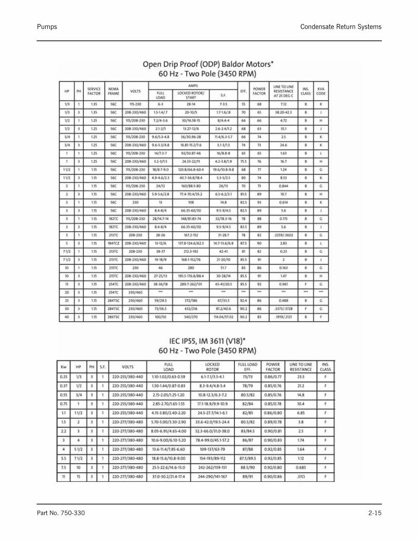
H.Motor Specifications
Pumps Condensate Return Systems
Part No. 750-330 2-15

Condensate Return Systems Pumps
2-16 Part No. 750-330

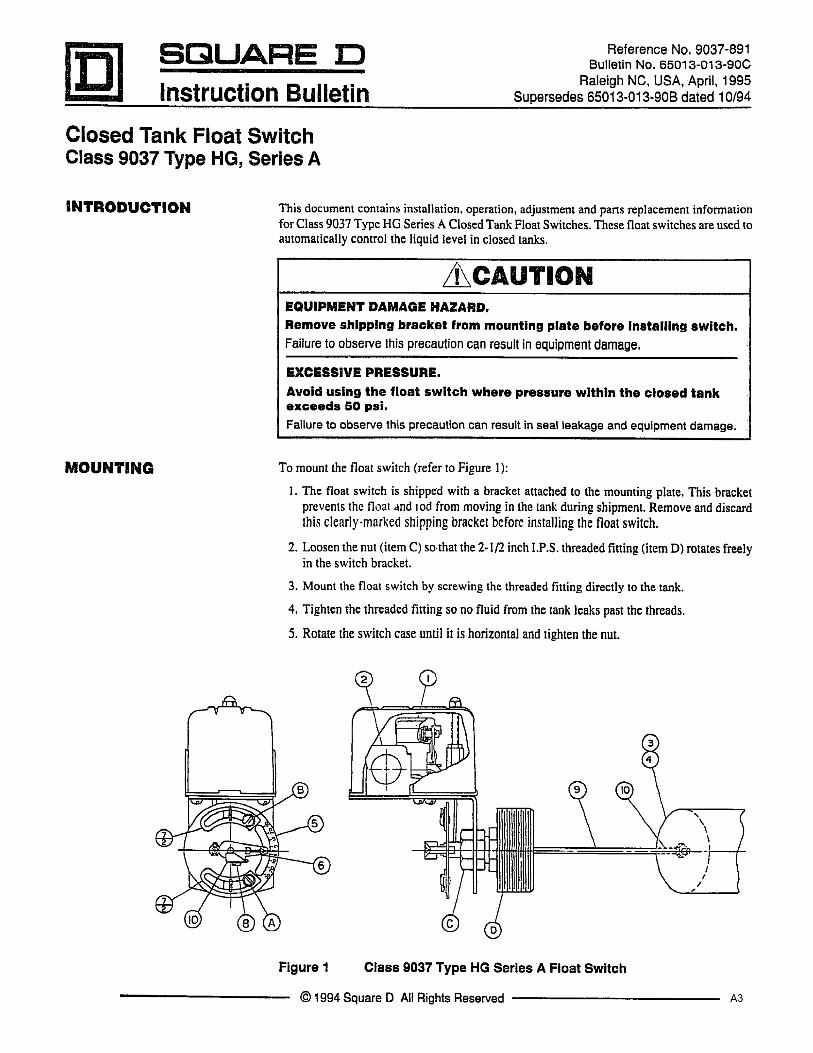
APPENDIX A — Float Switch
A1


APPENDIX B — Level Control
B1


SpecificationsSpecificationsSpecificationsSpecificationsSpecifications
Control DesignControl DesignControl DesignControl DesignControl Design: Solid state components enclosed in clearLexan plug-in style housing. Housing carries no NEMArating.Contact DesignContact DesignContact DesignContact DesignContact Design: SPDT (1 form C): one normally open (N.O.)and one normally closed (N.C.), non-powered contacts.Contact RatingsContact RatingsContact RatingsContact RatingsContact Ratings: 10A @ 120 or 240 VAC resistive, 1/3 H.P.@120 or 240 VAC.Contact LifeContact LifeContact LifeContact LifeContact Life: Mechanical- 5 million operations. Electrical-100,000 operations minimum at rated load.Supply VSupply VSupply VSupply VSupply Voltageoltageoltageoltageoltage: 24, 120, or 240 VAC models- factory set.Plus 10%, minus 15%, 50/60 Hz.Supply CurrentSupply CurrentSupply CurrentSupply CurrentSupply Current: 120, 240, 24 VAC, Relay energized 4.4 VA.Secondary CircuitSecondary CircuitSecondary CircuitSecondary CircuitSecondary Circuit: 12 VAC RMS voltage on probes, 1.5milli-amp current.SensitivitySensitivitySensitivitySensitivitySensitivity: Models operate from 0-1,000,000 OHMmaximum specific resistance- factory set.TTTTTemperatureemperatureemperatureemperatureemperature: -40 to 150° F. ambient.TTTTTerminalserminalserminalserminalserminals: All connections #6-32 screw type with pressureclamps.TTTTTime Delaysime Delaysime Delaysime Delaysime Delays: Standard, 0.5 seconds on rising level. Addi-tional time delays on rising and/or falling available as option.ListingsListingsListingsListingsListings: U.L. listed, Industrial Motor Control (508).
InstallationInstallationInstallationInstallationInstallation1. Install octal socket in appropriate enclosure using two (2) #6 or #8 metal screws.1A. Install rail mount socket on appropriate rail (DIN mount) in appropriate enclosure if applicable.2. Wire control per wiring diagram, following N.E.C. and local codes3. Install control module in socket.
This bulletin should be used by experienced personnel as a guide to the installation of series 16M controls. Selectionor installation of equipment should always be accompanied by competent technical assistance. We encourage you tocontact Gems Sensors or its representative if further information is required.
Sensitivities vs MaximumSensitivities vs MaximumSensitivities vs MaximumSensitivities vs MaximumSensitivities vs Maximum
Probe WProbe WProbe WProbe WProbe Wire Distanceire Distanceire Distanceire Distanceire Distance*****
***** Based on type MTW or THHN wire, #14 or #16 Awg.
Use copper (60/70° C) wire only. Torque to 20 inch pounds.
Dimensional DiagramDimensional DiagramDimensional DiagramDimensional DiagramDimensional Diagram
2-3/8”
3-1/2”
5/8”
2-3/4”
11/64”Dia.
2.0”
1-11/16”
1-5/32”
2-5/16”
WWWWWarrickarrickarrickarrickarrick®®®®® Series 16M Controls Series 16M Controls Series 16M Controls Series 16M Controls Series 16M ControlsInstallation and Operation BulletinInstallation and Operation BulletinInstallation and Operation BulletinInstallation and Operation BulletinInstallation and Operation Bulletin
Form 167Form 167Form 167Form 167Form 167Sheet P/N 100212-1Sheet P/N 100212-1Sheet P/N 100212-1Sheet P/N 100212-1Sheet P/N 100212-1
RevRevRevRevRev. E. E. E. E. E
A or K
B or L
C or M
D or N
E or P
F or R
G or S
SensitivitySensitivitySensitivitySensitivitySensitivity
CharacterCharacterCharacterCharacterCharacter
4.7
10
26
50
100
470
1,000
SensitivitySensitivitySensitivitySensitivitySensitivity
(K Ohms)(K Ohms)(K Ohms)(K Ohms)(K Ohms)
10,000
5,700
2,200
1,075
570
270
38
DistanceDistanceDistanceDistanceDistance
(Ft)(Ft)(Ft)(Ft)(Ft)
B3
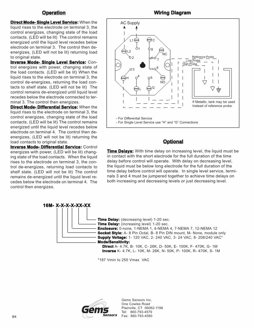
TTTTTime Delay: ime Delay: ime Delay: ime Delay: ime Delay: (decreasing level) 1-20 sec.TTTTTime Delay:ime Delay:ime Delay:ime Delay:ime Delay: (increasing level) 1-20 sec.Enclosure:Enclosure:Enclosure:Enclosure:Enclosure: 0-none, 1-NEMA 1, 4-NEMA 4, 7-NEMA 7, 12-NEMA 12Socket Style:Socket Style:Socket Style:Socket Style:Socket Style: A- 8 Pin Octal, B- 8 Pin DIN mount, M- None, module onlySupply VSupply VSupply VSupply VSupply Voltage:oltage:oltage:oltage:oltage: 1- 120 VAC, 2- 240 VAC, 3- 24 VAC, 8- 208/240 VAC*Mode/Sensitivity:Mode/Sensitivity:Mode/Sensitivity:Mode/Sensitivity:Mode/Sensitivity:
Direct Direct Direct Direct Direct A- 4.7K, B- 10K, C- 26K, D- 50K, E- 100K, F- 470K, G- 1M Inverse Inverse Inverse Inverse Inverse K- 4.7K, L- 10K, M- 26K, N- 50K, P- 100K, R- 470K, S- 1M
*187 Vmin to 255 Vmax VAC
16M- X-X-X-X-XX-XX16M- X-X-X-X-XX-XX16M- X-X-X-X-XX-XX16M- X-X-X-X-XX-XX16M- X-X-X-X-XX-XX
OperationOperationOperationOperationOperation
Direct Mode- Single Level ServiceDirect Mode- Single Level ServiceDirect Mode- Single Level ServiceDirect Mode- Single Level ServiceDirect Mode- Single Level Service::::: When theliquid rises to the electrode on terminal 3, thecontrol energizes, changing state of the loadcontacts. (LED will be lit) The control remainsenergized until the liquid level recedes belowelectrode on terminal 3. The control then de-energizes, (LED will not be lit) returning loadto original state.Inverse Mode- Single Level ServiceInverse Mode- Single Level ServiceInverse Mode- Single Level ServiceInverse Mode- Single Level ServiceInverse Mode- Single Level Service::::: Con-trol energizes with power, changing state ofthe load contacts. (LED will be lit) When theliquid rises to the electrode on terminal 3, thecontrol de-energizes, returning the load con-tacts to shelf state. (LED will not be lit) Thecontrol remains de-energized until liquid levelrecedes below the electrode connected to ter-minal 3. The control then energizes.Direct Mode- Differential ServiceDirect Mode- Differential ServiceDirect Mode- Differential ServiceDirect Mode- Differential ServiceDirect Mode- Differential Service::::: When theliquid rises to the electrode on terminal 3, thecontrol energizes, changing state of the loadcontacts. (LED will be lit) The control remainsenergized until the liquid level recedes belowelectrode on terminal 4. The control then de-energizes, (LED will not be lit) returning theload contacts to original state.Inverse Mode- Differential ServiceInverse Mode- Differential ServiceInverse Mode- Differential ServiceInverse Mode- Differential ServiceInverse Mode- Differential Service::::: Controlenergizes with power, (LED will be lit) chang-ing state of the load contacts. When the liquidrises to the electrode on terminal 3, the con-trol de-energizes, returning load contacts toshelf state. (LED will not be lit) The controlremains de-energized until the liquid level re-cedes below the electrode on terminal 4. Thecontrol then energizes.
OptionalOptionalOptionalOptionalOptional
TTTTTime Delaysime Delaysime Delaysime Delaysime Delays::::: With time delay on increasing level, the liquid must bein contact with the short electrode for the full duration of the timedelay before control will operate. With delay on decreasing level,the liquid must be below long electrode for the full duration of thetime delay before control will operate. In single level service, termi-nals 3 and 4 must be jumpered together to achieve time delays onboth increasing and decreasing levels or just decreasing level.
WWWWWiring Diagramiring Diagramiring Diagramiring Diagramiring Diagram
If Metallic, tank may be usedInstead of reference probe.
Low ProbeHigh Probe
- For Differential Service- For Single Level Service use “H” and “G” Connections
AC Supply
H
L G
L1
3
NC
C
5
1
2
NO
L2
6
4
7
8
Reference Probe
Gems Sensors Inc.One Cowles RoadPlainville, CT 06062-1198Tel: 860-793-4579Fax: 860-793-4580B4


e-mail: [email protected] Address: http://www.cleaverbrooks.com
Related Documents