Concurrent Prediction of Muscle Force and Cartilage Stress during Movement Trent M. Guess, PhD University of Missouri-Kansas City, Kansas City, MO RPI-NSF Workshop on Multiscale Modeling of Complex Data September 13, 2011 MUSCULOSKELETAL BIOMECHANICS RESEARCH LAB

Welcome message from author
This document is posted to help you gain knowledge. Please leave a comment to let me know what you think about it! Share it to your friends and learn new things together.
Transcript

Concurrent Prediction of Muscle Force and Cartilage Stress during Movement
Trent M. Guess, PhD University of Missouri-Kansas City, Kansas City, MO
RPI-NSF Workshop on Multiscale Modeling of Complex Data
September 13, 2011
MUSCULOSKELETAL BIOMECHANICS
RESEARCH LAB

Introduction n Knowledge of joint and tissue level loading during
movement can benefit n Ligament injury and repair n Tissue engineered cartilage and menisci n Degenerative joint disease
n Chondromalacia n Osteoarthritis (OA)
Full-depth OA 12 weeks after meniscal release procedure
Canine meniscal release model of OA
caudal horn attachments

Introduction n Primary computational tools of musculoskeletal
biomechanics n Multibody dynamics (rigid body dynamics) n Finite Element Method

Multibody Dynamics
n Musculoskeletal Modeling and Movement Simulation n Body level n Computationally efficient n Optimization techniques to
estimate muscle forces/activations nMuscle Redundancy
McLean S G, Su A and van den Bogert A J. 2003. Development and validation of a 3-D model to predict knee joint loading during dynamic movement. J Biomech Eng, 125:864-874.

Multibody Dynamics
McLean S G, Su A and van den Bogert A J. 2003. Development and validation of a 3-D model to predict knee joint loading during dynamic movement. J Biomech Eng, 125:864-874.
Simple Hinge
n Musculoskeletal Modeling and Movement Simulation n Rigid body
nNo deformable tissue
n Simplified representation of joints

Finite Element Method n Tissue level or joint level n Deformable (stress, strain) n Computationally intensive (development intensive)
n Simplified loading n Assumed or measured boundary conditions
nNo movement simulation
Weiss J A, Gardiner J C, Ellis B J, Lujan T J and Phatak N S. 2005. Three-dimensional finite element modeling of ligaments: technical aspects. Med Eng Phys, 27:845-861.

Musculoskeletal Interdependency n Interdependency of muscle force and tissue response
justifies a concurrent modeling approach
Muscle forces affect tissue loading
Tissue loading and joint motion affect muscle
forces

Body Joint Tissue
Multibody Data Driven Surrogate
n Goal n Concurrent Simluation – Body to Tissue Level
nMuscle Force n Anatomical Joints n Tissue (cartilage)

Compare Kinematics
Method (body to joint)
MRI
Cadaver Knee (55 yr, female, left
knee, 170 cm, 72 kg)
Dynamic Simulator
Gait Measurements
Validated Knee Model
Musculoskeletal Model
Hip Angle, Quad Force
Ankle Loads
Hip Position, Hip Load
Multibody Anatomical Knee Validation
Optotrak 3020 3D motion tracking system
Kansas Knee Simulator, University of Kansas, Lawrence
Loading is known Bone kinematics directly measured

5 second Walk Cycle

Compare Kinematics
Translation (mm) Orientation (deg) x y z 1 2 3
5.6 4.4 2.9 1.8 1.0 7.1
Kinematic Envelope of Motion (Tibia relative to Femur)
Derive zero-load length lo
Walk Cycle RMS Error (Tibia relative to Femur )
Femur Coord Sys
Tibia Coord Sys
X Y
Z
X
Z
Ligaments
Blenkevoort et al. 1991, Wismans et al. 1980

Multibody Cartilage n Macro
n Divides cartilage geometries into discrete elements n 4 mm x 4 mm cross-section n 72 discrete elements medial n 61 discrete element lateral
n Attaches each to the tibia n Defines a compliant contact
w/ femur cartilage

Multibody Cartilage n Advantage
n Prediction of contact pressure n Input to tissue surrogate
models n Greater control of contact
models n thickness, non-homogeneity, etc.

Multibody Menisci Meniscus geometry
from MRI
Macro divides geometries and connects w/ 6x6 stiffness matrices
Stiffness matrix parameters optimized to minimize position error of an identically loaded FE model
17 17

úúúúúúúú
û
ù
êêêêêêêê
ë
é
=
z
r
zrzz
rzrr
zr
TT
TKKKKKKKKK
K
000000000000000000
000000
][q
q
q
qqq
Stiffness matrix located between discrete elements
úúúúúúúú
û
ù
êêêêêêêê
ë
é
=
230000002500000025000
000330258300025270830008383320
][K
Objective Function: Displacement Error
Optimization
N/mm N-mm/(rad)
Multibody Menisci
100 N 100 N

ddd &)(exp BkFc +=
Multibody Menisci
Experiment
Model
Meniscus

Deformable Contacts
ddd &)(exp BkFc +=
Femur with Cartilage
Patella with Cartilage
Tibia
Cartilage Medial Meniscus
Lateral Meniscus
𝐹𝑐 = 𝑘𝛿𝑒𝑒𝑒 + 𝐵(𝛿)�̇�

Gait Measurements
n Motion (7 camera Vicon Mx-T40) n Plug-in Gait marker set
n Surface EMG (Delsys Myomonitor IV) n 8 muscles, left leg
n Ground Reaction Forces (AMTI OR-6)
Extension 16° 0.25 s
Flexion 87° 1.63 s

Musculoskeletal Model
LifeMOD (LifeModeler, Inc., San Clemente, CA)
Bushing
Spherical joints
Mirrored

Musculoskeletal Model 1.) Motion Driven Inverse Dynamic simulations to position knee
2.) Add Muscles (45 per leg) and quad attachments on patella
3.) Run Inverse Dynamics To “train” muscles
4.) Run Forward Dynamics muscle driven simulation

Results
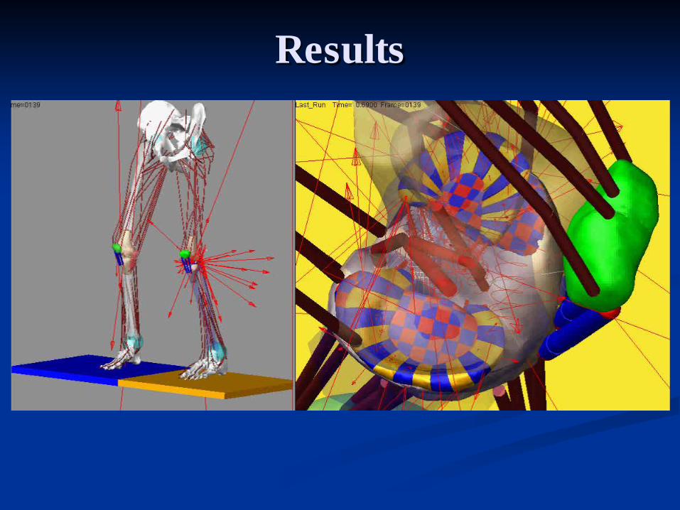
Results

Knee Loading Studies n With and without menisci
n Significant increase in peak tibia cartilage contact pressure without menisci
n Anterior Cruciate Ligament (ACL) transection (full and partial) n Lateral meniscus becomes “wedged” between the tibia and
femur for full and partial ACL transection n Small shift in peak contact pressure location
n Both findings are consistent with experimental measurements and observations n (Scarvell, Smith et al. 2005; Scarvell, Smith et al. 2005; Van de Velde, Bingham et al. 2009)
n Patello-femoral contact pressure n Magnitude of peak patella cartilage contact pressure does not
significantly change with altered vasti recruitment n Location of peak patella cartilage contact pressure does change
with altered vasti recruitment

Post
Ant
Intact Partial Full
Medial Plateau Extension
Post
Ant
Medial Plateau Flexion
Partial and Full Anterior Cruciate Ligament Transection

Post
Ant
Intact Partial Full
Lateral Plateau Extension
Post
Ant
Lateral Plateau Flexion
Partial and Full Anterior Cruciate Ligament Transection

Extension Flexion
Intact
Partial
Full
Location of Peak Contact Pressure

Predicted and Measured Ground Reaction Forces
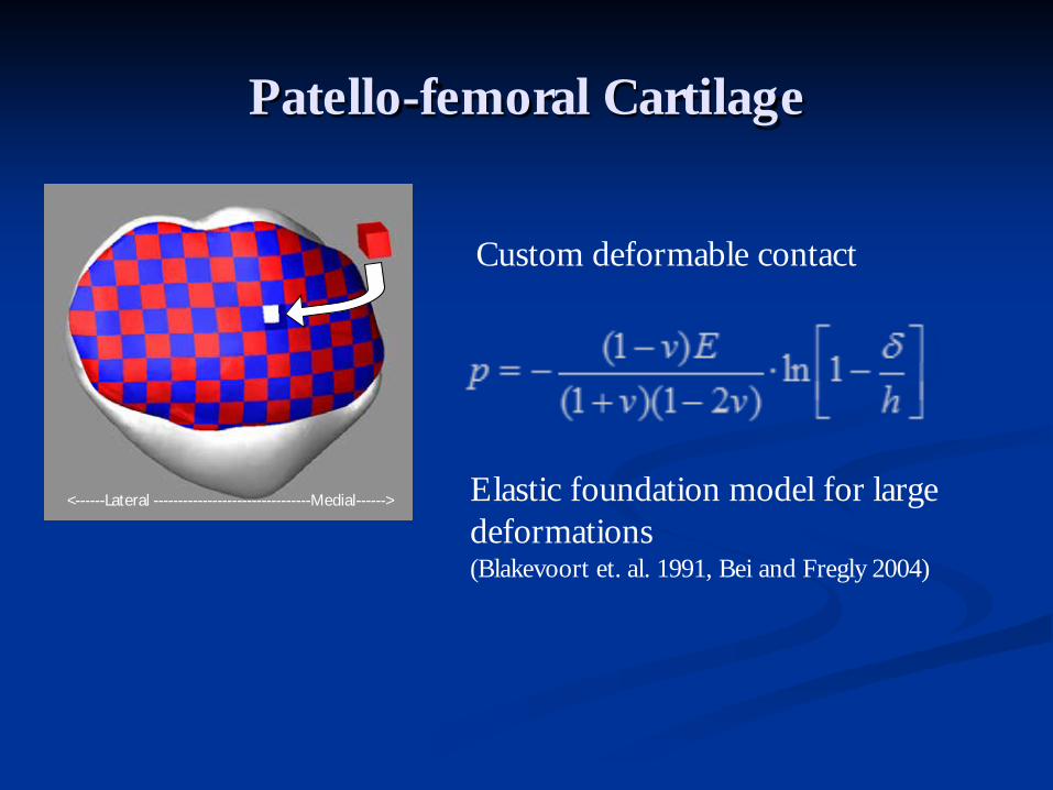
Patello-femoral Cartilage
<------Lateral --------------------------------Medial------>
Custom deformable contact
Elastic foundation model for large deformations (Blakevoort et. al. 1991, Bei and Fregly 2004)

Patello-femoral Cartilage
Uniform Vasti
Low VM
Low VL

Patello-femoral Cartilage
Uniform Vasti Low VM Low VL
11.6 MPa 85°
1.78 sec 11.1 MPa
84°
1.82 sec 11.6 MPa
87°
1.70 sec
121mm2 +56mm2 = 178mm2 139mm2 +43mm2 = 182mm2 175mm2 +50mm2 = 225mm2
<------Lateral ---------Medial------>
*
<------Lateral ---------Medial------>
*
<------Lateral ---------Medial------>
*

Patello-femoral Cartilage
Low VM <------Lateral -----------Medial------> <------Lateral -----------Medial------> <------Lateral -----------Medial------>
Uniform Vasti Low VL
Contact Pressure at 80° flexion

Future Work
- Patient specific, in vivo knee models - Geometries from MRI, ligament properties from in vivo laxity testing
- Modeling more activities (e.g. walking)

Tissue Models
n Multibody musculoskeletal models n Rigid body dynamics
nNo deformation n no stress and strain
n Limited to contact and interface loading n e.g. contact pressures, reaction forces
n Loading at tissue interfaces is not sufficient n Osteoarthritis n Mechanotransduction n Tissue engineering

d Femur Fc
FR
ddd &)(exp BkFc +=
Cartilage Surrogate
Cartilage bone interface reaction forces

Cartilage Surrogate
𝐹𝑐 = 𝑘𝛿𝑒𝑒𝑒 + 𝐵(𝛿)�̇�
𝐹𝑐
𝑅𝑅𝑅𝑅𝑅𝑅𝑅𝑅 𝐹𝑅𝐹𝑅𝑅𝐹
𝑇𝑅 𝑇𝑅𝐹𝐹𝑇𝑅 𝑀𝑅𝑀𝑅𝑀

n Goals n Identify and develop data-driven “surrogate” models
(black box nonlinear system identification) to predict von Mises stress from multibody reaction forces
n Develop a fast but accurate model with low computational footprint: nNeural nets are good candidates: besides their universal
function approximation properties, they can run in near “real time” post-training, even when representing a complex system.
Cartilage Surrogate

Cartilage Surrogate
n Multibody n Tune contact parameters
n Match FE displacement n Geometry, boundary
conditions n Outputs – rigid body
reaction forces
n Finite Element Analysis n Linear elastic cartilage
model n Geometry, boundary
conditions n Outputs – element von
Mises stress
Surrogate Training

Cartilage Surrogate
𝑅𝑅𝑅𝑅𝑅𝑅𝑅𝑅 𝐹𝑅𝐹𝑅𝑅𝐹
Von Mises Stress
Data Driven Surrogate

Cartilage Surrogate
n Trial 1 n Surrogate predicts von Mises stress on
center (blue) element n 15 inputs, 1 output n Advantage
n Could be subject independent nSimpler surrogate
n Disadvantage n Cartilage curvature n Cartilage thickness nNon-homogeneity nMulti-body cartilage segments are
independent n No reaction forces if not in contact with indenter n FE elements are interconnected

Cartilage Surrogate
Multibody Reaction Forces FE Stress

Cartilage Surrogate n Trial 2
n Surrogate predicts von Mises stress on all elements n For 20 x 20 grid, 1200 inputs, 400 outputs

Trial 2 Approach: Feed Forward Neural Networks
n NN setup: 20x20 grid of input elements (reaction forces), 20x20 grid of output elements (von Mises stress), one hidden layer with 10 neurons (hyperbolic tangent activation functions, 1200 inputs), and 400 linear output nodes.
.
.
.
.
.
.
h1
h2
h10
wji
.
.
.
Σ
Σ
Σ
input grid
output grid

Neural Net Training n Division of dataset (random sampling): 70% for calibrating
neural net parameters (training), 15% for iterative validation of training results, and 15% for blind test.
n Assumed that the system is memoryless (i.e. model outputs do not depend on past inputs).
n Scaled conjugate gradient for gradient descent solution to the neural net model parameters (goal: minimize the MSE on training set without increasing the MSE on validation set) n Other gradient decent MSE minimizers, such as Levenberg
Marquardt, can be too taxing on the memory and CPU resources, or they could be fast and light but not accurate enough (e.g. resilient backprop method)
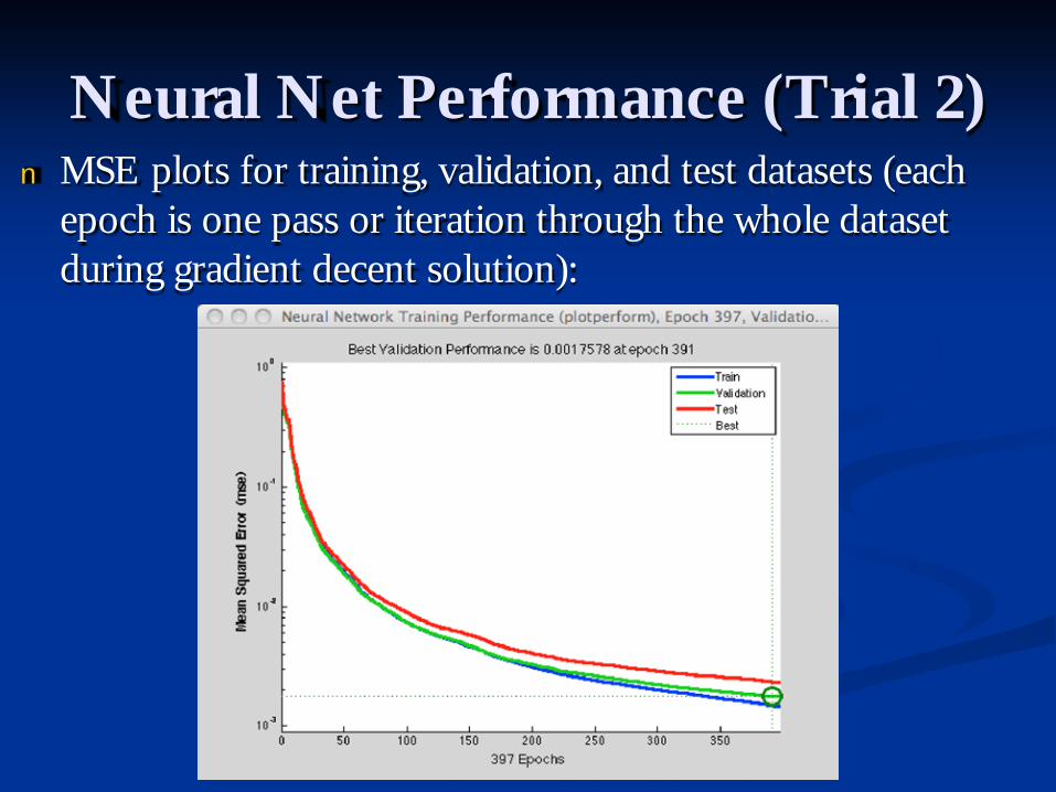
Neural Net Performance (Trial 2) n MSE plots for training, validation, and test datasets (each
epoch is one pass or iteration through the whole dataset during gradient decent solution):

Neural Net Performance (2) • Regression fit plots
for training, validation, and test subsetsà
• A good fit is represented by a data-target scatter plot that is tightly packed around the 45o line, also indicated by a correlation coefficient (R) that is close to 1.
• The neural net has successfully modeled not only the training but also the unseen test data.
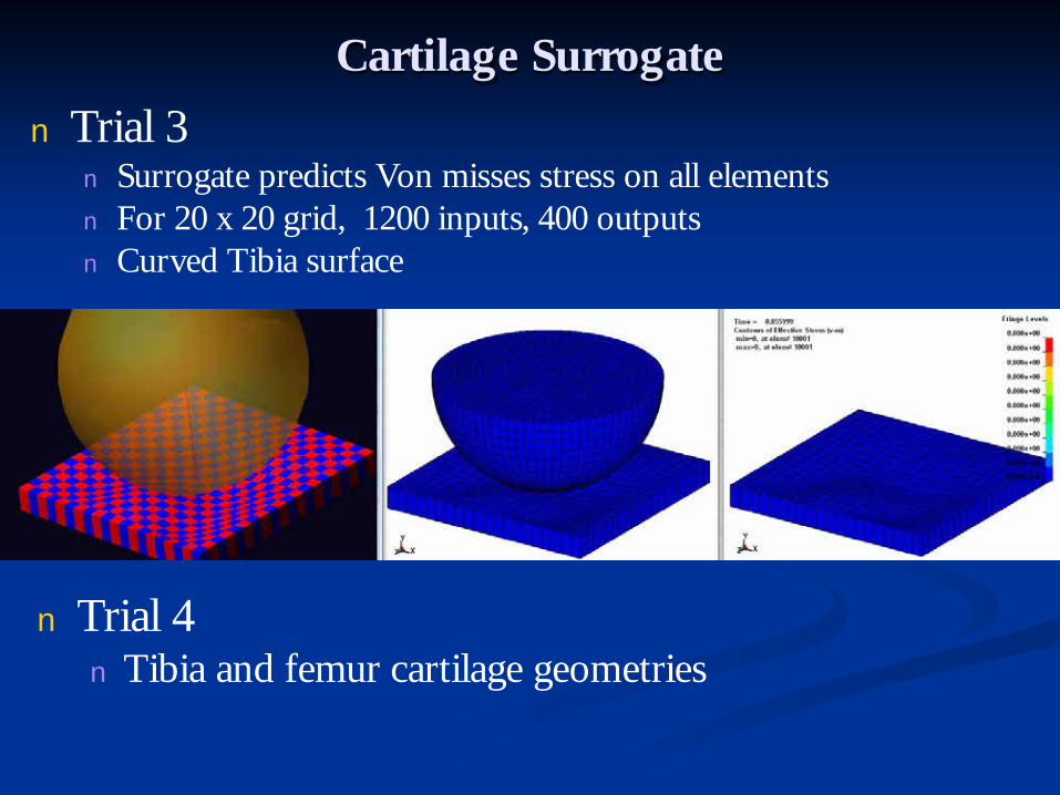
Cartilage Surrogate n Trial 3
n Surrogate predicts Von misses stress on all elements n For 20 x 20 grid, 1200 inputs, 400 outputs n Curved Tibia surface
n Trial 4 n Tibia and femur cartilage geometries

Acknowledgements n National Science Foundation
n CMMI-1039524 n CBET-0821459 n CMS-0506297
n National Institutes of Health n NIAMS RAR061698A
n Missouri Life Sciences Research Board n 09-1078
n Researchers n Reza Derakhshani, PhD n Antonis Stylianou, PhD n Yunkai Lu, PhD n Mohammad Kia, MS n Gavin Paiva, MS n Katherine Bloemker, MS n Sampath Bhashyam, BS

Thank You
Related Documents