IRC:112-2011 CODE OF PRACTICE FOR CONCRETE ROAD BRIDGES

Welcome message from author
This document is posted to help you gain knowledge. Please leave a comment to let me know what you think about it! Share it to your friends and learn new things together.
Transcript

IRC:112-2011
CODE OF PRACTICEFOR
CONCRETE ROAD BRIDGES

(
Digitized by the Internet Archive
in 2014
https://archive.org/details/govlawircy201 1112


IRC:112-2011
CODE OF PRACTICEFOR
CONCRETE ROAD BRIDGES
Published by:
INDIAN ROADS CONGRESSKama Koti Marg,
Sectors, R.K. Puram,
New Delhi -110 022
NOVEMBER - 2011
Price ^ 1000
(Packing & postage charges extra)
IRC:112-2011
First Published November, 2011
December, 2012
June, 2014 ( Incorporating all Amendments andErrata Published upto June, 2014)
Reprinted
Reprinted
(All Rights Reserved. No part of this publication shall be reproduced, translated or
transmitted in any form orby any means without the permission
of the Indian Roads Congress)
(The Official amendments to this document which may be considered necessary
from time to time would be published by the IRC in its periodical Indian
Highways These shall be considered as effective and as part
of the Code etc. from the date specified therein)
Printed at: India Offset Press, New Delhi
(1000 Copies)

IRC:112-2011
PERSONNEL OF THE BRIDGES SPECIFICATIONS ANDSTANDARDS COMMITTEE
(As on 25"^ October 2010)
1. Sinha.A.V.
(Convenor)
2. Puri.S.K.
(Co-Convenor)
3. Sharma.Arun Kumar(Member- Secretary)
4. Agan/val, K.N.
5. Alimchandani, C.R.
6. Banerjee, A.K.
7. Banerjee, T.B.
8. Basa, Ashok
9. Bandyopadhyay, Dr. T.K.
10. Bandyopadhyay, Dr. N.
11. Bongirwar, PL.
12. Bhasin, P.C.
13. Chakraborty, Prof. S.S.
14. Chakrabarti, S.P.
15. Dhodapkar.A.N.
16. Gupta, Mahesh17. Ghoshal.A.
18. Joglekar, S O.
19. Kand, Dr. C.V.
20. Koshi, Ninan
21. Kumar, Prafulla
22. Kumar, Vijay
23. Kumar, Dr. Ram
Director General (RD) & Spl. Secretary, Ministry of
Road Transport & Highways, New Delhi
Add!. Director General, Minstry of Road Tansport &Highways, New Delhi
Chief Engineer (B) S&R, Ministry of Road Transport
& Highways, New Delhi
Members
Director General (W) (Retd.), CPWD, Ghaziabad
Chairman & Managing Director, STUP Consultants
Ltd., MumbaiMember (Tech.), (Retd.) NHAI. New Delhi
Chief Engineer (Retd.), Ministry of Road Transport
& Highways, New Delhi
Director (Tech.), B. Engineers & Builders Ltd.,
Bhubaneswar
Joint Director General (Retd.), Institute for Steel
Dev. and Growth, Kolkata
Director, STUP Consultants Ltd., (P) Ltd. New Delhi
Advisor, L&T, MumbaiADG (B) (Retd.) MOST, New Delhi
Managing Director, Consulting Engg. Services (I)
Pvt. Ltd., New Delhi
Consultant. Span Consutants (P) Ltd., Noida
Chief Engineer (Retd.), Ministry of Road Transport &Highways, New Delhi
Executive Director (B&S), RDSO, LucknowDirector and Vice-President, STUP Consulants Ltd.,
Kolkata
Director (Engg. Core), STUP Consultants Ltd.,
MumbaiChief Engineer, (Retd.), MP PWD, Bhopal
Director General (RD) &Addl. Secy., MOST (Retd.),
GurgaonDirector General (RD) & AS (Retd.), MORT&H.Noida
E-in-C (Retd.), UP PWD, Noida
Chief General Manager, NHAI, New Delhi

IRC:112-2011
24. Kumar, Ashok
25. Manjure, P.Y.
26. Mukherjee, M.K.
27. Narain, A.D28. Ninan, R.S.
29. Patankar.V.L.
30. Rajagopalan, Dr. N.
31. Raina, Dr. V.K.
32. Rao. M.V.B.
33. Roy, Dr. B.C.
34. Sharma, R.S.
35. Sharan, G.
36. Sinna, N.K.
37. Saha. Dr. G.P.
38. Tandon, Prof. Mahesh
39. Velayutham, V.
40. Vijay, PB.
41. Diretor&Head
42. Addl. Director General
1 . President, IRC
2. Director General (RD) &Spl. Secretary
3. Secretary General
1. Merani, N.V.
2. Bagish, Dr. B.R
Chief Engineer, Ministry of Road Transport &Highways., New Delhi
Director, Freyssinet Prestressed Concrete Co. Ltd.,
MumbaiChief Engineer (Retd ), MORT&H. New Delhi
Director General (RD) &AS (Retd.), MORT&H, Noida
Chief Engineer (Retd.), MORT&H, New Delhi
Member (Tech.), NHAI. New Delhi
Chief Technical Advisor, L&T, Chennai
B-13, Sector-14, Noida-201301 (UP)
A-181 , Sarita Vihar, New Delhi
Executive Director, Consulting Engg. Services (I)
Pvt. Ltd., New Delhi
Past Secretary General, IRC. New Delhi
Director General (RD) & SS. (Retd.), MORT&H,New Delhi
Director General (RD) & SS, (Retd.), MORT&H,New Delhi
Exeutive Director, Construma Consultants (P) Ltd.,
MumbaiManaging Director, Tandon Consultants (P) Ltd.,
New Delhi
Director General (RD) & SS, (Retd.), MORT&H,New Delhi
Director General (W) (Retd.),CPWD, New Delhi
Bureau of Indian Standards, New Delhi
Directorate General Border Roads, New Delhi
EX'Officio Members
Liansanga, Engineer-in-Chief and Secretary,
PWD, Mizoram, Aizawl
(Sinha, A.V.) Ministry of Road Trasport &Highways, New Delhi
(Indoria, R.P) Indian Roads Congress, New Delhi
Corresponding Members
Principal Secretary (Retd.), Maharashtra PWD,MumbaiC-2/2013, Opp. D.PS., Vasant Kunj. New Delhi
(ii)
IRC:112-2011
SECTION 1 CONTENTS
Page No.
Section 1 -' Contents
Personnel of the Bridges Specifications and Standards Committee (i)
Section 2 Introductiori 1
Section 3 Definitions and Notations 3
3.1 Terms and Definitions 3
3.2 Notations ' 11
Section 4 General 16
4.1 Scope 16
4.2 Underlying Assumptions • \, 16
Sections Basis of Design - 18
5.1 Aims of Design 18
5.2 Limit State Philosophy of Design • 19
5.3 Limit States 20
5.4 Actions and their Combinations 21
5.5 Representative Values of Properties of Materials 23
5.6 Analytical Methods to Evaluate Behaviour of Structures 24
5.7 Design Based on Full Scale Testing 25
5.8 Durability Aspects ' 25
Section 6 Material Properties and their Design Values 28
6.1 General 28
6.2 Untensioned Steel Reinforcement 286.3 Prestressing Steel 31
6.4 Concrete 35
Section 7 Analysis ". 50
7.1 General Provisions 50
7.2 Analyses for Serviceability Limit States 53
7.3 Analyses for Ultimate Limit States ' 54
7.4 Torsional Effects 55
7.5 Combined Global and Local Effects 55
7.6 Structures and Structural Frames 55
7.7 Composite Concrete Construction 58
(iii)
IRC:112-2011
7.8 Structural Effects ofTime-Dependent Properties of Concrete
7.9 Prestressed Members and Structures
7.10 Design and Detailing for Curved Tendons in Thin Sections
7.11 Special Load Transferring Devices
Section 8 Ultimate Limit State of Linear Elements for Bendingand Axial Forces
8.1 Scope8.2 Strain and Stress Distribution at Ultimate Limit State
8.3 Biaxial Bending
Section 9 Ultimate Limit State of Two and Three DimensionalElements for Out of Plane and in Plane Loading Effects 76
9.1 Scope 769.2 One-Way and Two-Way Slabs and Walls 76
9.3 Sub-elements of Box Structures 76
9.4 General Solution for Two-Way Slabs, Walls and Shell Elements 77
Section 10 Ultimate Limit State of Shear, Punching Shear
and Torsion 80
10.1 Scope10.2 Design of Flexural Members for Shear
10.3 Design Method
10.4 Design for Punching Shear
10.5 Torsion
Section 11 Ultimate Limit State of Induced Deformation 110
11.1 General- ^- 110
11.2 Simplified Slenderness Criteria ';•
' 111
11.3 Non-linearAnalysis of Structure and Elements 115
11.4 Lateral Instability of Slender Beam 118
Section 12 Serviceability Limit State 12C
12.1 General 120
12.2 Stress Limitation 120
12.3 Limit State of Cracking 121
12.4 Limit State of Deflection 131
Section 13 Prestressing Systems 133
13.1 General 133
1 3.2 Anchorages for Post Tensioning Systems 1 33
60
61
66
68
69
69
6973
80
80
85
98
105
(iv)
IRC:112-2011
13.3 Mechanical Couplers 134
13.4 Sheathing Ducts andJoints 134
13.5 End Block Design and Detailing 136
13.6 Protective Grouting 138
13.7 Protection of Post Tensioned Tendons and Anchorages 139
Section 14 Durability 140
14.1 General 140
14.2 Common Mechanisms Leading to the Deterioration of Concrete Structures 140
14.3 Design for Durability 141
14.4 Additional Provisions for Specific Mechanisms of Deterioration 144
Section 15 Detailing: General Requirements 147
15.1 General 147
15.2 Reinforcing Steel 147
15.3 Prestressing Units 162
15.4 Coated Steels 169
Section 16 Detailing Requirements of Structural Members 171
16.1 General 171
16.2 Columns of Solid Section 171
16.3 R.C. Walls and Wall Type Piers 173
16.4 Hollow Piers/Columns 174
16.5 Beams 175
16.6 Solid Slabs 181
16.7 Corbels 185
16.8 Articulations 186
16.9 Deep Beams 186
16.10 Members with Unbonded Tendons 1 8716.11 Concentrated Forces 18716.12 Forces Associated with Change in Direction 18916.13 Indirect Supports 19016.14 Anchorage Zones for Post Tensioning Forces 190
Section 17 Ductile Detailing for Seismic Resistance 192
17.1 General 19217.2 Concrete Piers/Columns 192
17.3 Foundations 199
Section 18 Materials, Quality Control and Workmanship 200
18.1 General 200
18.2 Untensioned Stee! 200
(V)
IRC:112-2011
202
205
209
212
214
216
Normative Annexures
A-1 Actions, Design Situations and Combination ofActions 229A-2 Additional Information and Data about Properites of Concrete and Steel 235A-3 List of Standards and other Normative References 246A-4 Structural Design by "Working Loads/Allowable Stresses Method" 251
Informative Annexures
B-1 Concrete Shell Elements 268
B-2 Mechanisms of Deterioration of Concrete Structures 275
B-3 Effect of Live Loads on Deck Slabs . 278
18.3 Prestressing Steel
1 8.4 Material Ingredients of Concrete
1 8.5 Mix Proportions of Concrete
18.6 Acceptance Criteria
18.7 Grouting
1 8.8 Quality Control and Workmanship
(vi)
IRC:112-2011
SECTION 2 INTRODUCTION
The Design Criteria for Prestressed Concrete Road Bridges (Post-Tensioned Concrete);
IRC: 18 and Standard Specification and Code of Practice for Road Bridges Section ill,
Cement Concrete (Plain and Reinforced); IRC: 21, both based on working stress method,
were first published in December 1 965 and October 1 966 respectively. The last revisions
of these two documents were carried out in the year 2000. These two codes stands with-
drawn on publication of this Code.
The past two decades have seen unprecedented growth of knowledge in the field of
concrete bridges, development of new structural forms, new methods of computer-based
analysis and design and development of high strength materials. The need for a new
rationalized code for bridge structures in general, based on the limit state approach, in line
with international practices, has been felt for a long time. Keeping this in view, the task of
writing a new code based on the Limit State Method, was taken up in 2001 by the
Concrete (Plain, Reinforced and Prestressed) Structures Committee (B-4) and continued
over several terms of the Committee. The present composition of the Committee is as
follows:
. Koshi, Ninan Convenor
Mukherjee, M.K. Co-convenor
Viswanathan, T Member-Secretary
MembersBhowmick, Alok
Bhide. D.A.
Goel, Dr. Rajeev
Gupta, Vinay
Heggade, V.N.
Joglekar, S.G.
Mullick, Dr.A.K.
Mittal, Dr.A.K.
Patankar, V.L.
Rajeshirke, U.K.
Sharma, Aditya
Kurian, Jose
Vaidya, Avinash
Corresponding Member
Haridas, G.R
Ex-officio Members
President, IRC(Liansanga)
DG(RD) & SS. MORT&H(A.V, Sinha)
Secretary General, IRC
(R.P. Indoria)
1

IRC:112-2011
The task of drafting and finalization of the new Code of Practice for Concrete Road Bridge
was completed by the B-4 Committee in September 201 0. The draft was approved by the
Bridges Specifications and Standards Committee at its meeting held at New Delhi on
25^^ October 2010 and later by the Executive Committee on 27^^ October 2010. The draft
was discussed and approved by the Council of the Indian Roads Congress at the 1 92"^
Council Meeting held at Nagpur on 1 2'^ November 201 0.
The object of issuing the new Code of Practice for Concrete Road Bridges is to establish
a common procedure for design and construction of road bridges in India based on the
limit state method. This publication is meant to serve as a guide to both design and
construction engineers, but compliance with the provisions therein does not relieve them,
in any way, of the responsibility for the stability, soundness, durability and safety of the
structures designed and constructed by them.
The design and construction of road bridges require an extensive and thorough knowledge
of the science and technology involved and should be entrusted only to specially qualified
engineers with adequate experience of bridge engineering, capable of ensuring correct
design and execution of bridge works.
2
IRC:112-2011
SECTION 3 DEFINITIONS AND NOTATIONS
3.1 Terms and Definitions
3.1.1 Terms relating to structure
Structure
Organised combination of connected parts designed to carry loads and provide
adequate rigidity.
Structural Member
Physically distinguishable part of a structure, e.g. a column, a beam, a slab, a
foundation pile.
Structural System
Assemblage of load-bearing members of a structure and the way in which these
members function together.
Structural Model
Idealisation of the structural system used for the purposes of analysis, design
and verification.
3.1.2 Terms relating to design
Actions
Refer 3.1.3
Resistance
Capacity of a member or component, or a cross-section of a member or component of
a structure, to withstand actions without mechanical failure e.g. bending resistance,
buckling resistance, tension resistance.
Strength
Mechanical property of a material indicating its ability to resist actions, usually given In
units of stress, or magnitude of action.
3
IRC:112-2011
Reliability
Ability of a structure or a structural member to fulfil the specified requirements
including the design working life for which it has been designed. Reliability is usually
expressed in probabilistic terms.
Design Criteria
Quantitative formulations that describe the conditions to be fulfilled for each limit state.
Design Situations
Sets of physical conditions representing the real conditions occurring during a
certain time interval for which the design will demonstrate that relevant limit states
are not exceeded. ReferAnnexureA-1.
Transient Design Situation
Design situation that is relevant during a period much shorter than the design
working life of the structure and which has a high probability of occurrence.
Note: A transient design situation refers to temporary conditions of the structure,of use or
exposure, e.g. during construction or repair.
Persistent Design Situation
Design situation that is relevant during a period of the same order as the design
working life of the structure.
Note: Generally it refers to conditions of normal use.
Accidental Design Situation
Design situation involving exceptional conditions of the structure or its exposure,
including fire, explosion, impact or local failure.
Seismic Design Situation
Design situation involving exceptional conditions of the structure when subjected
to a seismic event.
4
IRC:112-2011
Design Working Life/Design Life
Assumed period for which a structure or part cf it is to be used for its intended
purpose with anticipated maintenance but without necessity of major repair.
Load Arrangement
Identification of the position, magnitude and direction of a free action.
Load Case
Compatible load arrangements, sets of deformations and imperfections
considered simultaneously with fixed/variable actions and permanent actions for a
particular verification.
Limit States
States beyond which the structure no longer fulfills the relevant design criteria.
Ultimate Limit States
States associated with collapse or with other similar forms of structural failure.
Note: These generally correspond to the maximum load-carrying resistance of
a structure or structural member.
Serviceability Limit States
States that correspond to conditions beyond which specified service requirements for a
structure or structural member are no longer met.
Irreversible Serviceability Limit States
Serviceability limit states where some consequences of actions exceeding the
specified service requirements will remain when the actions are removed.
Reversible Serviceability Limit States
Serviceability limit states where no consequences of actions exceeding the
specified service requirements will remain when the actions are removed.
Serviceability Criterion
Design criterion for a serviceability limit state.
5
IRC:112-2011
3.1 .3 Terms relating to actions (Also refer Annexure A-1
)
Action (F)
(a) Set offerees (loads) applied to the structure (direct action);
(b) Set of imposed deformations or accelerations caused for example,
by temperature changes, moisture variation, uneven settlement or
earthquakes (indirect action).
Effectof Action fHj
Effect of actions (or action effect) on structural members, (e.g. internal force,
moment, stress, strain) or on the whole structure (e.g. deflection, rotation).
Permanent Action fGJ
Action that is likely to act throughout a given reference period and for which the
variation in magnitude with time is negligible, or for which the variation is always
in the same direction (monotonic) until the action attains a certain limit value.
Variable Action CQJ
Action for which the variation in magnitude with time is neither negligible nor
monotonic.
Accidental Action (A)
Action usually of short duration, but of significant magnitude, that may rarely occur on a
given structure dunng the design life.
Note: An accidental action can be expected in some cases to cause severe global
consequences on structures unless appropriate measures such as provision of
alternative load path are taken.
Seismic Action (A^)
Action that arises due to earthquake ground motions.
Geotechnical Action
Action transmitted to the structure by the ground, fill or groundwater.
6
IRC:112-2011
Fixed Action
Action that has a fixed distribution and position over the structure or structural mennber
such that the magnitude and direction of the action are determined unambiguously for the
whole structure or structural member if this magnitude and direction are determined at one
point on the structure or structural member.
Free Action
Action that may have various spatial distributions over the structure.
Single Action
Action that can be assumed to be statistically independent in time and space of any other
acton acting on the structure.
Static Action
Action that does not cause significant acceleration of the structure or structural members.
Dynamic Action
Action that causes significant acceleration of the structure or structural members.
Quasi-static Action
Dynamic action represented by an equivalent static action in a static model.
Characteristic Value of an Action ("F^
Principal representative value of an action considered in the design process.
Note: (1 ) Insofar as a characteristic value can be fixed on statistical basis; it is chosen so
as to correspond to a prescribed probability of not being exceeded on the
unfavourable side during a 'reference period' taking into account the design
working life of the structure and the duration of the design situation.
(2) In absence of data for arriving at value as per (1 ) a nominal value is used which
conceptually performs the same function as that of characteristic value but is
not associated with any probability number.
7
IRC:112-2011
Nominal Value
Value fixed on non-statistical bases, for instance, on acquired experience or on physical
conditions, which may be used in place of characteristic value.
Reference Period
Chosen period of time that is used as a basis for assessing statistically variable actions.
Combination Value of a Variable Action (v|/ ,^^)'
Value chosen, insofar as it can be fixed on statistical basis, so that the probability that the
effects caused by the combination will be exceeded is approximately the same as by the
characteristic value of an individual action. It may be expressed as a determined part of
the characteristic value by using a factory^ </.
s.•
Frequent Value of a Variable Action (h/,(2k)
Value determined, insofar as it can be fixed on statistical basis, so that either the total
time, within the reference period, during which it is exceeded is only a small given part of
the reference period, or the frequency of it being exceeded is limited to a given value. It
may be expressed as a determined part of the characteristic value by using a factor v|/,<l
.
Quasi-Permanent Value of a Variable Action (y/j^J
Value of a variable action as a fraction of characteristic load, which is present for
substantial part of the reference period.
Accompanying Value of a Variable Action (y/QJ
Value of a variable action that accompanies the leading action in a combination.
Note: The accompanying value of a variable action may be the combination value, the frequent
value or the quasi-permanent value.
Representative Value of an Action {F)
Value used for the verification of a limit state. A representative value may be the
characteristic value (F^) or an accompanying value {^F^.
Design Value of an Action (F^)
Value obtained by multiplying the representative value by the partial factor y,.
8
IRC:112-2011
Combination of Actions
Set of design values used for the verification of the structural reliability for a limit state
under the simultaneous influence of different actions.
3.1.4 Terms relating to material and product properties
Characteristic Value (X^ or R^)
Value ofa material or product property having a prescribed probability of not being attained
in a hypothetical unlimited test series. This value generally corresponds to a specified
fractile of the assumed statistical distribution of the particular property of the material or
product. A nominal value is used as the characteristic value in some circumstances.
Design Value of a Material or Product Property (X^ or
Value obtained by dividing the characteristic value by a partial factor or or, in special
circumstances, by direct determination.
Nominal Value of a Material or Product Property (X^ or R^)
Value normally used as a characteristic value and established from an appropriate
document.
Design Value of a Geometrical Property (a^)
Generally a nominal value. Where relevant, values of geometrical quantities may correspond
to some prescribed fractile of the statistical distribution.
3.1 .5 Terms relating to structural analysis
Structural Analysis
Procedure or algorithm for determination of action effects in every point of a structure.
Note: A structural analysis may have to be performed at three levels using different models:
global analysis, member analysis, local analysis.
Global Analysis
Determination, in a structure, of a consistent set of either internal forces and moments or
stresses that are in equilibrium with a particular defined set of actions on the structure, and
depend on geometrical, structural and material properties.
9
IRC:112-2011
First order linear-elastic analysis without redistribution
Elastic structural analysis based on linear stress/strain or moment/curvature taws and
performed on the initial geometry of the structure.
First order linear-elastic analysis with redistribution
Linear elastic analysis in which the internal moments and forces are modified for structural
design, consistent with the given external actions and without more explicit calculation of
the rotation capacity.
Second order linear-elastic analysis
Elastic structural analysis, based on linear stress/strain and moment/curvature laws, applied
to the geometry of the deformed structure.
First order non-linear analysis
Structural analysis, perfonned on the initial geometry of the stmcture, that takes account of
the non-linear deformation properties of materials.
Note: This definition includes first order analysis with non-linearity of any type, including plastic
behaviour with or without hardening (e.g. bilinear diaphragms of stress-strain).
First order elastic-perfectly plastic analysis
Structural analysis performed on the initial geometry of the structure based on moment/
curvature relationships consisting of a linear elastic part followed by a plastic part without
hardening.
Second order non-linear analysis
Structural analysis, performed on the geometry ofthe defomned structure thattakes account
of the non-linear defonnation properties of materials.
Second order elastic-perfectly plastic analysis
Structural analysis performed on the geometry of the displaced (or deformed) structure
based on moment/curvature relationships consisting of a linear elastic part followed by a
plastic part without hardening.
10
IRC:112-2011
Elasto-plastic analysis (first or second order) c
Structural analysis that uses stress-strain or moment/curvature relationships consisting of
a linear elastic part followed by a plastic part with or without hardening.
Rigid Plastic Analysis
Analysis, performed on the initial geometry of structure, that uses limit analysis theorem for
direct assessment of ultimate loading.
Note: The moment-curvature law is assumed without elastic deformation and without
hardening in plastic stage.
3.2 Notations
The following notations are generally used unless otherwise specified in the text or
figures.
3.2.1 Latin upper case letters
A Accidental action
A Cross-Sectional area;
Ag Cross-Sectional area of concrete
Ap Area of prestressing tendon or tendons
A, Cross-Sectional area of reinforcement
\min Minimum cross-sectional area of shear reinforcement
A^^ Cross-Sectional area of shear reinforcement
D Diameter of mandrel
E Effect of action; or general expression for modulus of elasticity asper the context.
Eg Tangent modulus of elasticity of normal weight concrete at a stress
of a^=0.
^ceffEffective modulus of elasticity of concrete
E^^ Design value of modulus of elasticity of concrete
E^ Secant modulus of elasticity of concrete
EJt) Tangent modulus of elasticity of normal weight concrete at a stress
of =0 and time t.
E Design value of modulus of elasticity of prestressing steel
Design value of modulus of elasticity of reinforcing steel
E, Bending stiffness
Static equilibrium
F Action
F^ Design value of an action
F^ Characteristic value of an action
Characteristic value of permanent action
11
IRC:112-2011
Second moment of area of concrete Section
Length
Bending momentDesign value of the applied internal bending momentAxial force
Design value of the applied axial force (tension or compression)Prestressing force
Initial force at the active end of the tendon immediately after
stressing
Characteristic value of a variable action
Characteristic fatigue load
Resistance (also refer 3. 1 .4)
Internal forces and moments or first moment of area as percontext
Serviceability limit state
Torsional moment
Design value of the applied torsional moment
Ultimate limit state
Shear force
Design value of the applied shear force
Refer definition in 3. 1 .4
3.2.2 Latin lowercase letters
a Distance
a Geometrical data
Aa Deviation for geometrical data
b Overall width of a cross-section, or actual flange width in a T or L beam
b Width of the web of T, I or L beams
d Diameter; Depth
d Effective depth of a cross-section
d^ Largest nominal maximum aggregate size
e Eccentricity
.Design Value of Ultimate bond stress
Compressive strength of concrete
Design value of concrete compressive strength
Characteristic compressive cube strength of concrete at 28 days
f^^ Mean value of concrete cube compressive strength
f^^i^Characteristic axial tensile strength of concrete
f^,^^ Mean value of axial tensile strength of concrete
Tensile strength of prestressing steel
f characteristic tensile strength of prestressing steel which is same as
/p corresponding to breaking load given in the relevant IS codes listed
in Table 18.2
12
/
L
M
NN
Ed
Ed
RS
fat
SLST
TEd
ULS
V,Ed
IRC:112-2011
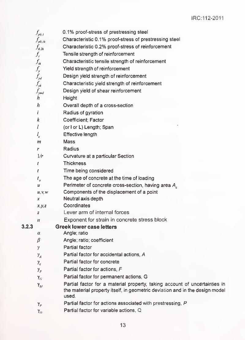
fp^^, 0.1% proof-Stress of prestressing Steel
Characteristic 0.1% proof-stress of prestressing steel
fg^i^Characteristic 0.2% proof-stress of reinforcement
Tensile strength of reinforcement
Characteristic tensile strength of reinforcement
Yield strength of reinforcement
Design yield strength of reinforcement
Characteristic yield strength of reinforcement
f^^ Design yield of shear reinforcement
h Height
h Overall depth of a cross-section
i Radius of gyration
k Coefficient; Factor
/ (or I or L) Length; Span
Effective length
m Mass
r Radius
1/r Curvature at a particular Section
t Thickness
/ Time being considered
The age of concrete at the time of loading
u Perimeter of concrete cross-section, having area
u, V,w Components of the displacement of a point
X Neutral axis depth
x.y,z Coordinates
z Lever arm of internal forces
n Exponent for strain in concrete stress block
3.2.3 Greek lower case letters
Angle; ratio
Angle; ratio; coefficient
Partial factor
Partial factor for accidental actions, A
Partial factor for concrete
Partial factor for actions, F
Partial factor for permanent actions. GPartial factor for a material property, taking account of uncertainties in
the material property itself, in geometric deviation and in the design model
used.
Partial factor for actions associated with prestressing, PPartial factor for variable actions, G
y
yA
yc
yp
la
yxf
13
IRC:112-2011
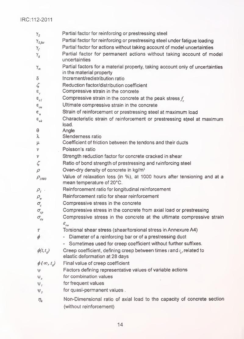
Partial factor for reinforcing or prestressing steel
Ysj&iPartial factor for reinforcing or prestressing steel under fatigue loading
Partial factor for actions without taking account of model uncertainties
Partial factor for permanent actions without taking account of modeluncertainties
y„ Partial factors for a material property, taking account only of uncertainties
In the material property
5 Increment/redistribution ratio
^ Reduction factor/distribution coefficient
8^ Compressive strain in the concrete '
t^j Compressive strain in the concrete at the peak stress/^
Ultimate compressive strain in the concrete
Strain of reinforcement or prestressing steel at maximum load
Characteristic strain of reinforcement or prestressing steel at maximumload.
0 Angle'
X Slendemess ratio
\i Coefficient of friction t}etween the tendons and their ducts
V Poisson's ratio
V Strength reduction factor for concrete cracked in shear
f Ratio of bond strength of prestressing and reinforcing steel
p Oven-dry density of concrete in kg/m'
Pjooo Value of relaxation loss (in %), at 1000 hours after tensioning and at a
mean temperature of 20*C.
Pi . Reinforcement ratio for longitudinal reinforcement
p^ Reinforcement ratio for shear reinforcement;
<T^ Compressive stress in the concrete
Compressive stress in the concrete from axial load or prestressing
^cu Compressive stress in the concrete at the ultimate compressive strain
f Torsional shear stress (shear/torslonal stress in Annexure A4)
^ - Diameter of a reinforcing bar or of a prestressing duct
- Sometimes used for creep coefficient without further suffixes.
^t, tf) Creep coefficient, defining creep between times i and , related to
elastic deformation at 28 days
^(°ojf) Final value of creep coefficient
v|/ Factors defining representative values of variable actions
for combination values
for frequent values
for quasi-permanent values
.
i7t Non-Dlmensional ratio of axial load to the capacity of concrete section
(without reinforcement)
14
IRC:112-2011
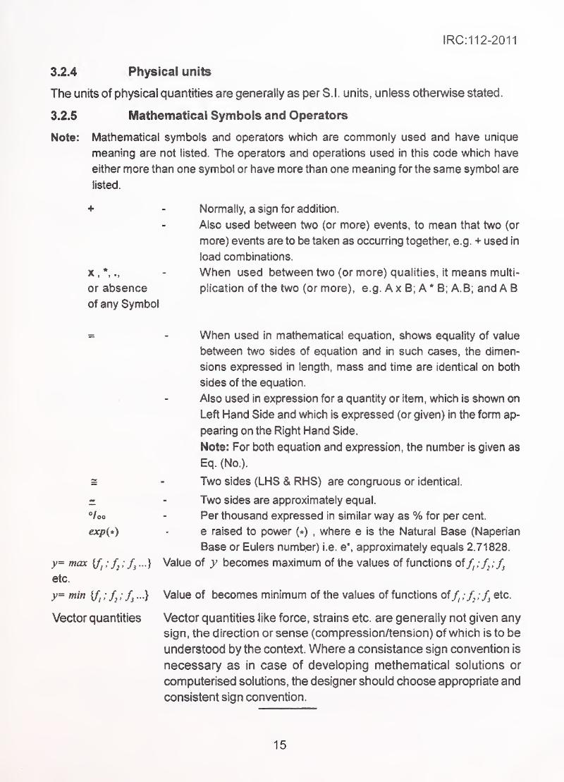
3.2.4 Physical units
The units of physical quantities are generally as per S.I. units, unless othen/vise stated.
3.2.5 Mathematical Symbols and Operators
Note: Mathematical symbols and operators which are commonly used and have unique
meaning are not listed. The operators and operations used in this code which have
either more than one symbol or have more than one meaning for the same symbol are
listed.
+ .-
^- Normally, a sign for addition.
Also used between two (or more) events, to mean that two (or
more) events are to be taken as occurring together, e.g. + used in
load combinations.
X,
*, ., - When used between two (or more) qualities, it means multi-
or absence plication of the two (or more), e.g. Ax B; A* B; A.B; and A B
of any Symbol
= - When used in mathematical equation, shows equality of value
between two sides of equation and in such cases, the dimen-
sions expressed in length, mass and time are identical on both
sides of the equation.
Also used in expression for a quantity or item, which is shown on
Left Hand Side and which is expressed (or given) in the form ap-
pearing on the Right Hand Side.
Note: For both equation and expression, the number is given as
Eq. (No ).
s - Two sides (LHS & RHS) are congruous or identical.
i - Two sides are approximately equal.
®/oo ^ Per thousand expressed in similar way as % for per cent.
exp(*) - e raised to power (*) , where e is the Natural Base (Naperian
Base or Eulers number) i.e. e*, approximately equals 2.71828.
y= max {/) ; ; ...} Value of y becomes maximum of the values of functions off, :f,:f^
etc.
y= mm {/) ; /, ; ...} Value of becomes minimum of the values of functions of if^f^ etc.
Vector quantities Vector quantities like force, strains etc. are generally not given any
sign, the direction or sense (compression/tension) of which is to be
understood by the context. Where a consistance sign convention is
necessary as in case of developing methematical solutions or
computerised solutions, the designer should choose appropriate and
consistent sign convention.
15
IRC:112-2011
SECTION 4 GENERAL
4.1' Scope
The Code of Practice for Concrete Road Bridges, hereinafter referred to as the 'Code',
this code strives to establish common procedures for the design and construction of
concrete road bridges including footbridges in India.
The requirements specified in the Code aim at achieving construction of safe, serviceable,
durable and economical bridges. It covers design principles, detailed design criteria and
practical rules, material specifications, workmanship, quality control and all such aspects
which affect the characteristics/ability of the bridge to meet the aims.
This Code deals with the structural use of plain cement concrete, reinforced concrete,
prestressed concrete and composite construction using concrete elements in bridges and
is applicable to all structural elements using normal weight concrete (density in the range
of (24 ± 4 kN/m^) and made using cements, aggregate, mineral admixtures, chemical
admixtures and water, as given in the Section dealing with material specifications in the
Code.
All provisions of the Code may not be applicable for hybrid structural systems, or for
structures using other types of concrete. However, for concrete portion of hybrid elements/
staictures and for other type of concrete, relevant provision of this Code may be used. The
term "other types of concrete" includes, but is not restricted to:
(1) Light Weight Concrete (density <20 kN/m^) and Heavy Weight
Concrete (density >28 kN/m^).
(2) Concretes using cements, aggregates, mineral and chemical
admixtures other than those covered in Section 1 8.
(3) Concretes with specially modified properties.
Such uses shall be based on the specialist knowledge, specialist literature and/or
experimental data at the discretion and responsibility of owners/designers.
Requirements of blast resistance and fire resistance are not covered in the Code.
4.2 Underlying Assumptions
The applicability of this document rests on the following assumptions:
(1 ) The choice of structural system and the design of the structure are
made by appropriately qualified and experienced person nel.
16

IRC:112-2011
(2) Execution is carried out by personnel having appropriate
qualification, skill and experience.
(3) Adequate supervision and quality control are provided during all
stages of design and construction.
(4) The construction materials and products are provided and used as
specified by relevant national standards.
(5) The intended levels of properties of material adopted in the design
are available.
(6) The structure is used as intended and is maintained adequately.
17
IRC:112-2011
SECTION 5 BASIS OF DESIGN
5,1 Aims of Design
5JJ General performance reqyiremerite
The bridge, as a complete structural system and its structural elements should perform
their functions adequately and safely, with appropriate degrees of reliability during design
life and during construction. It should withstand all actions, consisting of applied and induced
loads as well as environmental influences liable to occur, retaining its structural integrity,
and also withstand accidental loads (e.g. barge impact/vehicular impact) and earthquake
loads without causing damage, which is disproportionate to the causative event Adequacy
of performance is defined in terms of serviceability, safety, durability and economy.
5J .2 Reliability aspects and coda! approach
The term 'degree of reliability' is used to indicate the acceptably low level of probability of
failure in meeting the expected performance during a specified period of time.
Determination of the reliability measured in terms of statistical probability requires
knowledge of statistical parameters which define loading and material strengths. This data
together with knowledge of structural models of resistance enable evaluation of structural
performance in probabilistic terms. At the present state of knowledge, determination of
reliability is possible only in limited load cases for simple structures. The Code, therefore,
strives to achieve the desirable degree of reliability by approximate methods based upon
a combination of the following:
(1 ) Known statistical parameters describing properties of materials and
actions.
(2) Deterministic models of structural behaviour.
(3) The international practices and past experience of acceptable/
unacceptable performance of structures.
(4) Partial factors for actions and resistance models based on
calibration and rationalisation of existing international practices.
5.1 .3 Safety, serviceability, durability and economy
The requirements of the Code directly address safety, serviceability and durability aspects.
18
IRC:112-2011
Economy is Indirectly addressed by:
(1) Allowing maximum exploitation of materials and specifying use of
technologies which are consistent with the minimum/desirable
standards of safety, serviceability and durability,
(2) Accepting appropriate levels of economic risks while specifying
performance levels by taking into consideration different design
situations, load combinations (events), importance of structure in
view of consequences of failure, and by specifying different
intended design lives for replaceable and non-replaceable parts.
5.2 Limit State Philosophy of Design_
•
(1) The response of the structure when subjected to different
magnitudes of loads lies in different states (domains). 'Limit States'
are defined as limits of domains beyond which the structure does
not meet specified performance criteria.
In 'Limit State Philosophy' of design, various boundaries of
acceptable/unacceptable performance are defined together with
the circumstances in which such performances are expected.
(2) Two basic groups of limit states are considered;
(a) Ultimate Limit States (ULS): These limit states cover static
equilibrium and failure of structural elements or structure as
a whole, when acted upon by 'ultimate design loads'.
(b) Serviceability Limit States (SLS): These limit states deal with
the condition of the structure subjected to influence of
'serviceability design loads'. These conditions include level of
internal stress, fatigue failure, deflection, damage to structural
element such as cracking, and discomfort to users due to
vibrations.
(3) The representative values of actions and combination of actions
representing different design situations are defined. The
representative values of loads are modified by using load factors
for each of the basic limit states, which are then combined using
combination factors. The combination factors take into account the
probability of simultaneous occurrence of loads.
19
IRC:112-2011
(4) The response of the structure is calculated using principles of
mechanics and simplified established models describing behaviour
of concrete members. These methods also account for inherent
geometric variations which are kept within acceptable construction
tolerances.
(5) The response of the structure is required to lie within acceptable
domain for different combinations of actions.
(6) The structure designed by following this philosophy, and constructed
by satisfying other stipulations of the Code are deemed to meetthe general performance requirements stipulated in Clause 5.1.1.
5.3 Limit States
The structure shall be designed for the following limit states:
5.3.1 Ultimate limit states (ULS)
5.3.1.1 Limit state of equilibrium
When subjected to various design combinations of ultimate loads the bridge or any of its
components, considered as a rigid body, shall not become unstable.
5.3.1.2 Limit state of strength
The bridge or any of its components shall not lose its capacity to sustain the various ultimate
load combinations by excessive deformation, transformation into a mechanism, rupture,
crushing or buckling.
5.3.2 Serviceability limit states (SLS)
5. 3. 2. 1 Limit state of internal stress
The internal stresses developed in the materials of structural elements shall not exceed
the specified magnitudes when subjected to combination of serviceability design actions.
The stresses are to be estimated using resistance models to represent the behaviour of
structure, as stipulated in the Code.
5.3.2.2 Limit state ofcrack control
(1) The cracking of reinforced, partially prestressed, and prestressed
concrete structures under serviceability load combinations is kept
within acceptable limits of crack widths in such a way as not to
adversely affect the durability or impair the aesthetics.
20
IRC:112-2011
(2) Alternatively, the control of cracking is deemed to be satisfied by
following restrictions on amount and spacing of reinforcement.
5.3.2.3 Limit state of deformation
(1) The deformation of the bridge or its elements when subjected to
combination of design actions shall not adversely affect the proper
functioning of its elements, appurtenances, and riding quality.
(2) Deformations during construction shall be controlled to achieve
proper geometry of finished structure.
5. 3. 2.4 Limit state of vibration
(1) For footbridges or component of bridges specifically designed to
carry footway loading, the direct verification of vibration limits is
required , for which specialist literature may be referred
.
(2) For special types of bridges and their components dynamic effects
under action of wind are required to be calculated and verified to
be within acceptable limits. Model tests are required under certain
circumstances.
(3) For other types of bridges, the limit state of vibration under
serviceability load combinations is deemed to be satisfied by limiting
deflection of elements.
5. 3. 2. 5 Limit state of fatigue
The bridge or any of its components shall not lose its capacity to carry design loads by
virtue of its materials reaching fatigue limits due to its loading history. For carrying out
fatigue verification, specialist literature may be referred.
However, fatigue verification is not necessary for the following:
a) For Reinforced concrete structures when the stress in the tensile reinforce-
ment is less than 300 MPa under Rare Combination of Serviceability Limit
State as against 0.8 f^ specified in Clause No. 12.2.2.
b) For prestressed concrete structures under the frequent combination of action
and prestressing force, only compressive stresses occur at the extremeconcrete fibers, under Serviceability Limit State.
5.4 Actions and their Combinations
5.4.1 Types of action
(1) An action is:
- Direct action, i.e. force (load) applied to structure.
- Indirect action, i.e. forces arising from imposed or constrained
deformation, such as that caused by settlement, temperature
changes, seismic acceleration and impact loads.
21
IRC:112-2011
(2) Actions are classified:
(a) By their variation In time (duration of application)
:
- PermanentActions (G), e.g. self-weight,
- Variable Actions (Q), e.g. imposed live loads,
- Accidental Actions (A), e.g. barge Impact loads.
Some variable actions acting for long durations are treated on
par with permanent actions. These are called 'Quasi-Permanent'
actions.
(b) By their nature and/or by response of the structure to them:
- Static actions are those which do not cause significant
acceleration of members on which they act.
- Dynamic actions are those which cause significant
acceleration of members on which they act.
Some dynamic actions can be represented by 'Quasi-Static' actions,
which are the static values producing equivalent or representative
response (stress/deformation) in the structure caused by the
dynamic action.
(3) Prestressing force (P) is a permanent action with time-dependent
variation.
5.4.2 Characteristic and combinational values of actions
5.4.2.1 Characteristic value
The characteristic value of an action is generally the main representative value, which can
be based upon the statistical distribution of magnitudes of action (e.g. a mean value, or
upper or lower fractile value). Alternatively, a representative 'nominal value' is specified
which is treated as a characteristic value.
A single value is generally specified, except where the design is sensitive to variation of
magnitude in which case lower and upper values (also referred to as 'inferior' and
'superior' values respectively) are also specified in addition to mean value. These maybe specified as absolute values or as a multiple of characteristic value.
5.4.2.2 Combinational value
(1) A structure during its construction and service life is acted upon by
various direct or indirect actions at different times in different
22
IRC:112-2011
combinations, representing various design situations. Some of
these situations are represented by a few combinations chosen for
design checks, for which the response of the structure is calculated
and verified not to exceed the limit states.
(2) The combinational value is represented by characteristic value
multiplied by a factor, which takes into account the probability of
•
' ^ simultaneous occurrence of the most likely unfavourable values of
several independent actions.
(3) Various design situations (represented by various load
combinations) for which different limit states are to be checked are
given in IRC:6 and Annexure A-1. All components of the
structure are not required to be verified for all limit states and all
possible combinations. The requirements or exemptions are covered
under relevant clauses of the Code dealing with such components.
5.5 " Representative Values of Properties of Materials
5.5.1 General
The constituent materials of structure acting singly or in a composite action with other
materials have certain properties which determine their own response and the behaviour
ofthe structural elements when acted upon by various loads. Some of the material and
stmctural properties depend upon the type of load, its duration, magnitude, and the loading
history. Some properties are time-dependent, while others are affected by environmental
actions. Some properties depend upon the physical size (dimensions) of the structural
member.
Almost all the properties exhibit statistical variation in their numerical values. Many of the
properties show strong co-relations with other properties, which pemiit sufficiently accurate,
if not exact, estimation of their value from the values of other properties by use of
mathematical expressions. Correlations pre based on laboratory or field observations and
statistical regression analysis. A few of these properties are chosen as descriptive and/or
representative properties of the materials (e.g. self compacting concrete). They are often
used to define the material itself or its grade (e.g. concrete grade M 40 and reinforcing
steel Fe 500). Standard methods of testing for measuring such values are specified by
Bureau of Indian Standards or other national / international authorities.
23
IRC:112-2011
5.5.2 Representative values
Depending upon the purpose of carrying out the evaluation, one or more of the following
three representative values are used in the design:
(1 ) Average or statistical mean value.
(2) A lower fractile value (inferior value) based on the statistical
distribution function or the statistical mean value suitably reduced
by a factor.
(3) An upper fractile value (superior value) based on the statistical
distribution function, or the statistical mean value suitably increased
by a factor.
The representative values of commonly used materials are defined in Section 6.
5.5.3 Other methods of assessment of properties
When higher level of accuracy is desired in evaluating response of the structure, use of
more accurate values of other properties than those obtained from co-relations used in
Section 6 and Annexure A-2 are required. In such cases, these should be based upon one
of the following:
(1) More accurate and elaborate methods/expressions which
incorporate more number of factors influencing the required values
reported in specialist literature from established and reliable
sources.
(2) Laboratory/field testing using standard methods of testing and
measurements and based on sufficient number of tests as required
by statistical methods of establishing desired accuracy (usually
95 percent confidence level). Normally, to establish mean and
standard deviation, not less than 30 samples are required.
5.6 Analytical Methods to Evaluate Behaviour of Structures
5.6.1 Global analysis of structure
The purpose of this analysis is the verification of overall stability and establishment of
effects of action on the whole or a part of the structure. These effects include the
distribution of internal forces and moments as well as stresses, strains, curvatures, rotations
and displacements in static or dynamic modes. To carry out analysis the geometry, boundary
conditions and behaviour of the structure and its components need to be idealised. The
24
IRC:112-2011
structure is idealised by considering it as made up of elements, which can be linear, two
dimensional or three dimensional. Classical methods of mechanics or modem techniques
such as finite element can be used for analysis. The mathematical model should be capable
of evaluating the desired effect with sufficient accuracy.
5.6.2 Local analyses
In addition to global analysis of structure or its elements, local analyses will be necessary
particularly in the regions of stress concentrations and geometric discontinuities.
5.6.3 Idealisation, modelling and adequacy
Behaviour of structure and Its components can be represented to various degrees of
accuracy. The general principles as well as normally used methods are covered in
Section 7. The idealisation and modelling should be adequate to estimate the relevant
action effects. The interaction of properties of constituent materials with heterogeneous
properties should be appropriately taken into account.
Appropriate methods of analysis such as elastic analysis, non-elastic analysis with limited
redistribution, plastic analysis with actual or idealised material properties are indicated
depending upon the level of accuracy required. Necessity of including the second order
effects in the analysis is indicated where it is important.
5.7 Design Based on Full Scale Testing
Design of some elements like crash barriers, fenders, prestressing anchors, etc., can be
based on full scale tests of the prototype. The failure load/capacity is defined as that
causing either irreparable damage, or pre-defined limit of deformation.
5.8 Durability Aspects
The durability recommendations of this Code are based on the strategies adopted regarding
aspects indicated in the following Clauses. These strategic options/choices in design,
detailing and construction are intended to ensure durability as well as serviceability and
safety, for a period not less than the intended service life of the structure.
5.8.1 Design service life
The following table indicates the 'design service life' of some common types of bridges.
25
IRC:112-2011
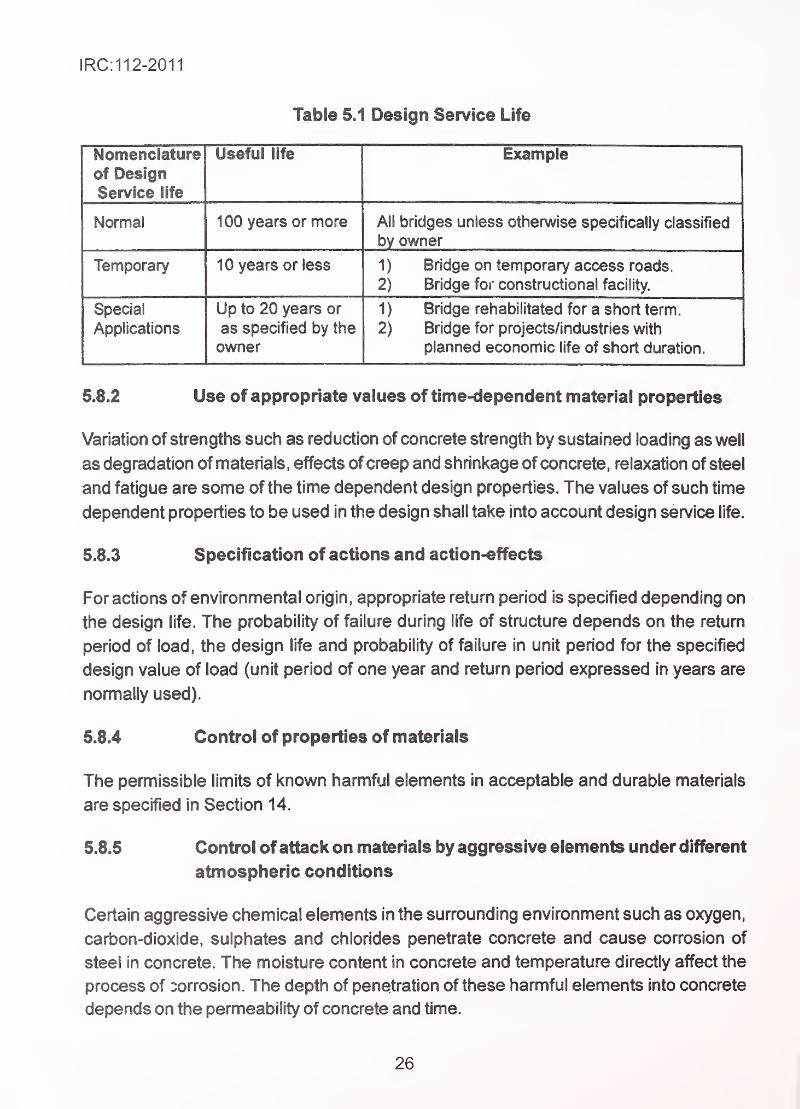
Table 5.1 Design Service Life
Nomenciaiureof DesignService life
useiui lire example
iNurmai inn v/Asr<£ nr nninir® All KriHnoc i inloec /^fhAru/ica cnar'ifif^allv; ^^laeeifiAHr\ii uiiuycd uiiiC'do uiiiciwioc ^ptswiTiuasiy Qassiiieu
by owner
Temporary 1 0 years or less 1) Bridge on temporary access roads.
2) Bridge for constructional facility.
Special
Applications
Up to 20 years or
as specified by the
owner
1 ) Bridge rehabilitated for a short term.
2) Bridge for projects/industries with
planned economic life of short duration.
5.8.2 Use of appropriate values of time-dependent material properties
Variation of strengths such as reduction of concrete strength by sustained loading as well
as degradation of materials, effects of creep and shrinkage of concrete, relaxation of steel
and fatigue are some of the time dependent design properties. The values of such time
dependent properties to be used in the design shall take into account design service life.
5.8.3 Specification of actions and action-effects
For actions of environmental origin, appropriate return period is specified depending on
the design life. The probability of failure during life of structure depends on the return
period of load, the design life and probability of failure in unit period for the specified
design value of load (unit period of one year and return period expressed in years are
nomrially used).
5.8.4 Control of properties of materials
The pemnissible limits of known harmful elements in acceptable and durable materials
are specified in Section 14.
5.8.5 Control of attack on materials by aggressive elements under different
atmospheric conditions
Certain aggressive chemical elements in the surrounding environment such as oxygen,
carbon-dioxide, sulphates and chlorides penetrate concrete and cause corrosion of
steel in concrete. The moisture content in concrete and temperature directly affect the
process of corrosion. The depth of penetration of these harmful elements into concrete
depends on the permeability of concrete and time.
26

1RC:112-2011
The process of deterioration is mitigated by recommending suitable materials (such as
concrete having certain qualities), cover to steel, improved corrosion resistant steel, etc.,
for different classes of environment.
Externally applied protective barriers are indicated in certain circumstances.
5.8.6 Maintenance
Periodic inspection and adequate maintenance are prerequisites for ensuring durability
of structure. All records of inspection and repairs should be available to concerned authority.
27
1RC:112-2011
SECTION 6 MATERIAL PROPERTIES AND THEIR DESIGN VALUES
6.1 General V
6.1 .1 The analysis and design of the structure and its elements require knowledge
of the physical, chemical, mechanical, load-dependent, time-dependant and process-
dependent properties of its materials. The properties include those goveming the composite
action of materials acting interactively with one another as well as acting individually.
Simplified rules describing these properties which are consistent with the analysis and
design models permitted by this Code are given in the following Clauses.
6.1 .2 In special cases where more exact analyses and models of behaviour are
to be considered, more representative rules describing these properties are needed, someofwhich are given in AnnexureA-2. In addition, reference to international Codes, published
literature, laboratory test reports or field tests, may also be made. However, the reliability
of the referenced source and/or reproducibility of test values should be established.
6.1 .3 Some of the properties are strongly influenced by activities of construction
and work procedures. Use of appropriate technological methods, deployment of qualified
and trained work force combined with methods of quality assurance are requisite pre-
conditions for realising in practice the properties assumed in the design. Minimum
acceptable standards of workmanship are given in Section 18.
6.1 .4 Specifications of structural materials to be used in construction of bridges
shall conform to the Indian Standards given in Section 18.
6.1 .5 Materials conforming to other international standards can be used provided
they meet the minimum requirements (lower or upper values as the case may be) given in
the relevant Indian Standards and this Code.
6.2 Untensioned Steel Reinforcement
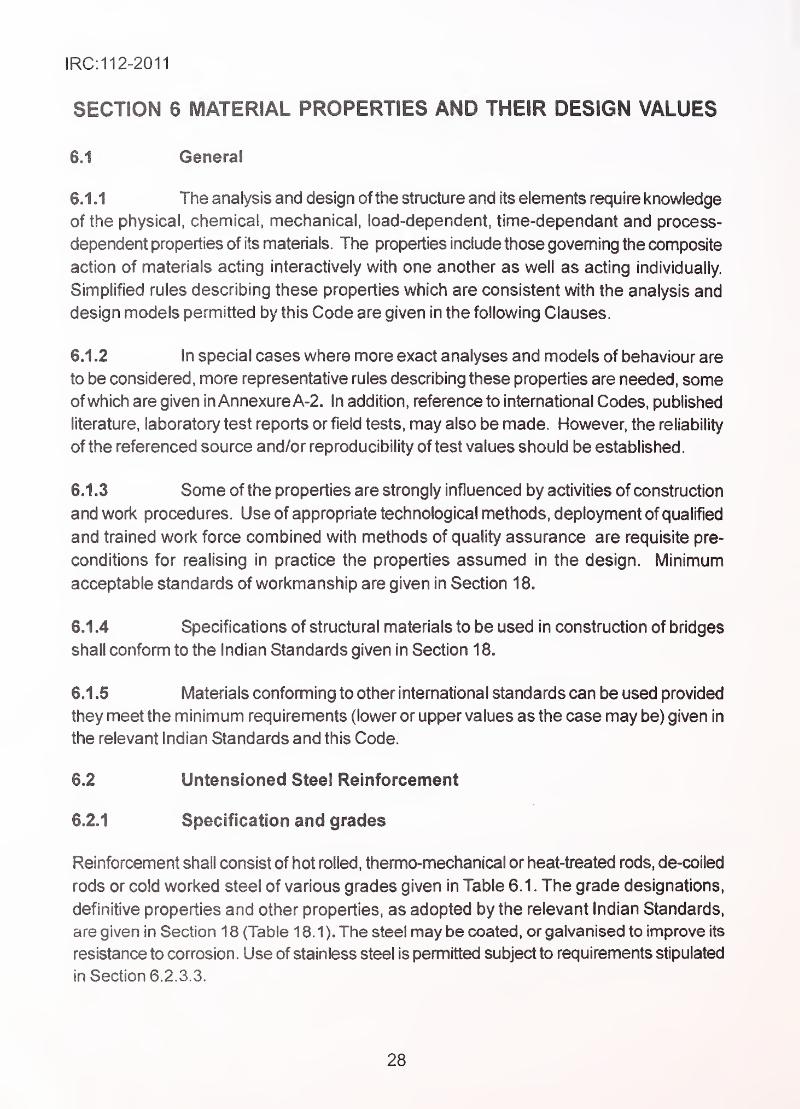
6.2.1 Specification and grades
Reinforcement shall consist of hot rolled, thermo-mechanical or heat-treated rods, de-coiled
rods or cold worked steel of various grades given in Table 6.1. The grade designations,
definitive properties and other properties, as adopted by the relevant Indian Standards,
are given in Section 1 8 (Table 18.1). The steel may be coated, or galvanised to improve its
resistance to corrosion. Use of stainless steel is permitted subject to requirements stipulated
in Section 6.2.3.3.
28
IRC:112=2011
Table 6.1 Grades of Reinforcing Steel
Type of steel Grade/Designation
Mild Steel (MS) Grade-!
High Yield Strength Deformed Steel (HYSD Steel) Fe415
Fe415D
Fe 500
Fe 500D
Fe550
Fe 550D
Fe 600
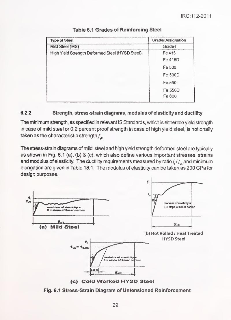
6.2.2 Strength, stress-strain diagrams, modulus of elasticity and ductility
TTie minimum strengtli, as specified in relevant IS Standards, which is either the yield strength
in case of mild steel or 0.2 percent proof strength in case of high yield steel, is notionally
fallen as the characteristic strength/^.
The stress-strain diagrams of mild steel and high yield strength deformed steel are typically
as shown in Fig. 6.1 (a), (b) & (c), which also define various important stresses, strains
and modulus of elasticity. The ductility requirements measured by ratio/; / and minimum
elongation are given in Table 18.1. The modulus of elasticity can be taken as 200 GPa for
design purposes.
ft
(a) Mild Steel
(b) Hot Rolled / Heat Treated
HYSD Steel
(c) Cold Worked HYSD Steel
Fig. 6.1 Stress-Strain Diagram of Untensloned Reinforcement
29
IRC:112-2011,
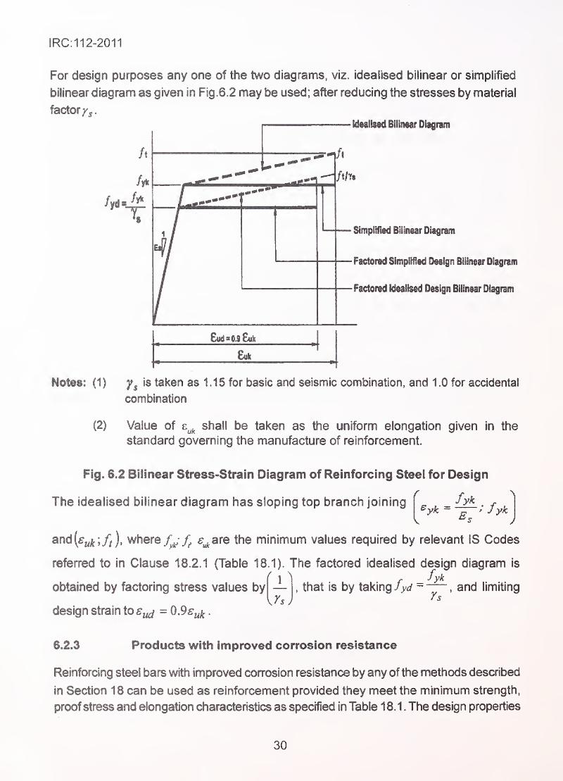
For design purposes any one of the two diagrams, viz. idealised bilinear or simplified
bilinear diagram as given in Fig.6.2 may be used; after reducing the stresses by material
factor/^.
/t
/t/Tf.
Simplified Bilinear Dlagtam
' riciorea oimpiifieu yesign Diiinear Diagrsm
. Factored Idealised Design Bilinear Diagram
8uh
: (1) is taken as 1.15 for basic and seismic ccmbination, and 1.0 for accidental
combination
(2) Value of e^^ shall be taken as the uniform elongation given in the
standard governing the manufacture of reinforcement.
Fig. 6.2 Bilinear Stress-Strain Diagram of Reinforcing Steel for Design
The idealised bilinear diagram has sloping top branch joining fykfyk
J
and(%^;/i), where s^ate the minimum values required by relevant IS Codes
referred to in Clause 18.2.1 (Table 18.1). The factored idealised design diagram is
obtained by factoring stress values by
design strain to ffj^ = 0,9ffy^
.
'±1, that is by taking fyd ~
, and limiting
6.2.3 Products with improved corrosion resistance
Reinforcing steel bars with improved corrosion resistance by any of the methods described
in Section 18 can be used as reinforcement provided they meet the minimum strength,
proof stress and elongation characteristics as specified in Table 18.1. The design properties
30
IRC:112-2011
are considered to be the same as per Clause 6.2.2 except as given in Clause 6.2.3.2 for
epoxy coated reinforcement.
6.2.3.1 Galvanised reinforcement
The strength as well as elongation and bond properties of galvanised reinforcement are
not adversely affected by galvanising.
6.2.3.2 Epoxy-coated reinforcement
Reinforcing bars conforming to IS 1 786 can be coated by fusion bonded epoxy conforming
to IS 13620-1993.
The bond of coated reinforcement is lowered by upto 20 percent of that of uncoated
reinforcement. In detailing of steel the lap length and anchorage lengths given in Section
1 5 should be increased by 25 percent.
6.2.3.3 Stainless steel reinforcement
Properties of stainless steel reinforcement shall not be inferior to the carbon steel
reinforcement of corresponding strength class. For bond properties reference should be
made to the relevant code or established on basis of tests.
Note: The Indian Standard for stainless steel reinforcement is under preparation. The British
Standard BS:6744:2001 , which covers suitable stainless steels for use as reinforcement
may be refenred.
6.3 Prestressing Steel
6.3.1 Specifications, grades, strength, elongation and relaxation
Prestressing steel in the following forms, conforming to Indian Standards given in
Section 18. Tables 18.2 to 18.5 shall be used.
Plain or indented wires '
'
Stress-relieved multi°p!y strands .
High tensile steel bars
Steels conforming to other intemational standards but satisfying the minimum strength,
elongation, and relaxation characteristics of Indian Standards may be used.
6.3.2 lyiinimum sizes
The steels of nominal sizes and ultimate strengths having characteristics as mentioned in
Table 18.2 to 18.5 are pennitted for use in bridges designed for normal life (Refer
Table 5.1).
31
IRC:112-2011
For other bridges mentioned in Table 5. 1 , steels having smaller diameters than those given
in the Tables 18,3 to 18.5 but otherwise meeting the requirements of Indian Standards
mentioned therein, can be used.
6.3.3 Other properties
6.3.3. f Ductility
The requirements of ductility of steel are deemed to be satisfied by use of steel having the
minimum elongations specified in Section 18.3.
The wires/strands shall also pass the bendability test (reverse bending) as specified in
relevant Indian Standards.
6.3.3.2 Tolerance on size/diameter
The relevant Indian Standards specify the manufacturing tolerances on diameters/size of
various products which remain valid for general acceptance ofthe material and the source
of supply.
6.3.4 Coated wires/strands
The wires/strands confonning to Indian Standards can be provided with protective coatings,
like galvanising orepoxy coating, carried out in specialised manufacturing units. However,
if the technological processes affect any of the mechanical and physical properties, such
modified properties should be taken into account in design.
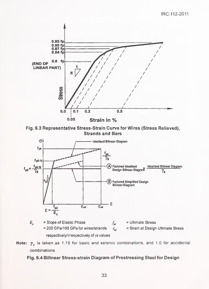
6.3.5 Stress-strain properties for design
Typical stress/strain and ultimate elongation of prestressing wires and strands are shown
in Fig. 6.3 and 6.4. The actual E value varies between 195 GPa and 216 GPa. For
prestressing steels, the stress is to be taken as force divided by the nominal cross
sectional area.
For the purpose of analysis and design, either the diagrams shown in Fig. 6.3 or the
simplified bilinear diagram as shown in Fig. 6.4 (any one of shapeA and shape B) can be
used. The 'E' value of 200 GPa for wires and 195 GPa for strands can be used in the
design up to the elastic limit (first part of bilinear diagram unless more exact value is
required, (e.g. for verification of elongation during stressing operations, which should be
taken on the basis of actual field tests.)
32
IRC:112-2011
0.95 fp0.90 fp0.87 fp0.84 fp
(END OFLINEAR PART)
i8
CO
0.0
Fig. 6.3 Representative Stress-Strain Curve for Wires (Stress Relieved),
Strands and Bars
Idealised Bilinear Diagram
{a) Factored Idealised . idealised Bilinear DiagramDesign Bilinear Oiagrarn
{§) Factored SImpiifigd DesignBilinear Diagram
Ep = Slope of Elastic Phase = Ultimate Stress
= 200 GPa/1 95 GPa for wires/strands = Strain at Design Ultimate Stress
respectively/i rres pectively of ys values
Note: is taken as 1.15 for basic and seismic combinations, and 1 .0 for accidental
combinations
Fig. 6.4 Bilinear Stress-strain Diagram of Prestressing Steel for Design
33
IRC:112-2011
^ fpOAk -
^— ;fpQAk
The idealised bilinear diagram shown in Fig. 6.4 has sloping top branch joining
to [^ukJpk J, where fpo.ik is taken from manufacturer's data, or
established by tests in field. In absence of specific data.j^^^^can be taken as 0.87 fpk .
For strands, stress values shall be based on the nominal cross-sectional area given in
Table 18.4. The idealised design shape (A) is obtained by factoring idealised bilinear
diagram by — , and taking design strain and stress not greater than 0.9 , with
corresponding vaiue of design stress.
For simplified bilinear design diagram shape (B), having horizontal branch, the strain limit
need not be checked.
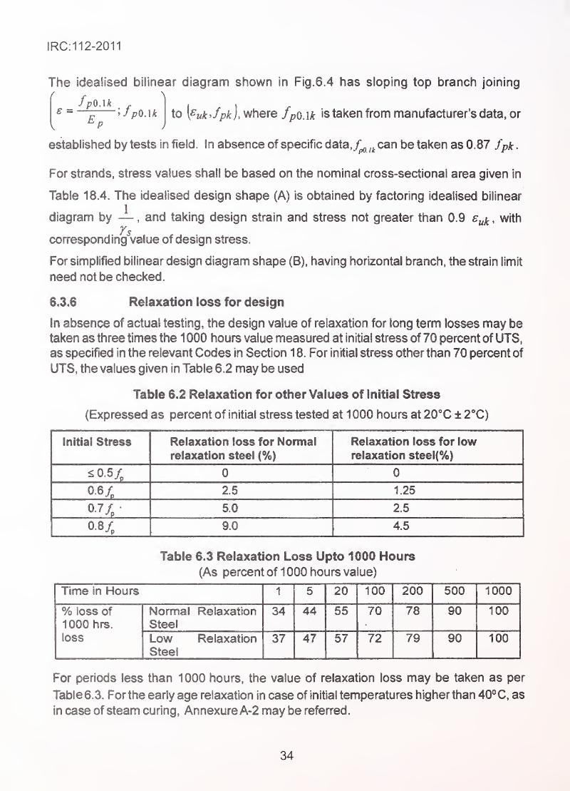
6.3.6 Relaxation loss for design
In absence of actual testing, the design value of relaxation for long term losses may be
taken as three times the 1 000 hours value measured at initial stress of 70 percent of UTS,
as specified in the relevant Codes in Section 1 8. For initial stress other than 70 percent of
UTS, the values given in Table 6.2 may be used
Table 6.2 Relaxation for other Values of initial Stress
(Expressed as percent of initial stress tested at 1 000 hours at 20X ± 2X)
Initial Stress Relaxation loss for Normalrelaxation steel (%)
Relaxation loss for lowrelaxation steel(%)
^0.5/„ 0 0
0.6X 2.5 1.25
5.0 2.5
10.8/p 9.0 4.5
Table 6.3 Relaxation Loss Upto 1000 Hours
(As percent of 1 000 hours value)
Time in Hours 1 5 20 100 200 500 1000
% loss of
1000 hrs.
loss
Normal Relaxation
Steel
34 44 55 70 78 90 100
Low Relaxation
Steel
37 47 57 72 79 90 100
For periods less than 1000 hours, the value of relaxation loss may be taken as per
Table 6.3. For the early age relaxation in case of initial temperatures higher than 40° C, as
in case of steam curing , AnnexureA-2 may be referred
.
34
IRC:112-2011
6.4 Concrete
Cement, fine aggregates, coarse aggregates, mineral admixtures and water constitute
the main material ingredients of concrete. Chemical admixtures are added to fresh concrete
to improve its workability. For specification of constituents of concrete
Section 18 and the relevant Indian Standards may be referred. For use of concretes
designed to have special and different characteristics from those given in this Section,
specialist literature may be referred
.
6.4.1 Grade designation
Concrete shall be designated by type and its grade-designation based on characteristic
strength as described in Table 6.4, where:
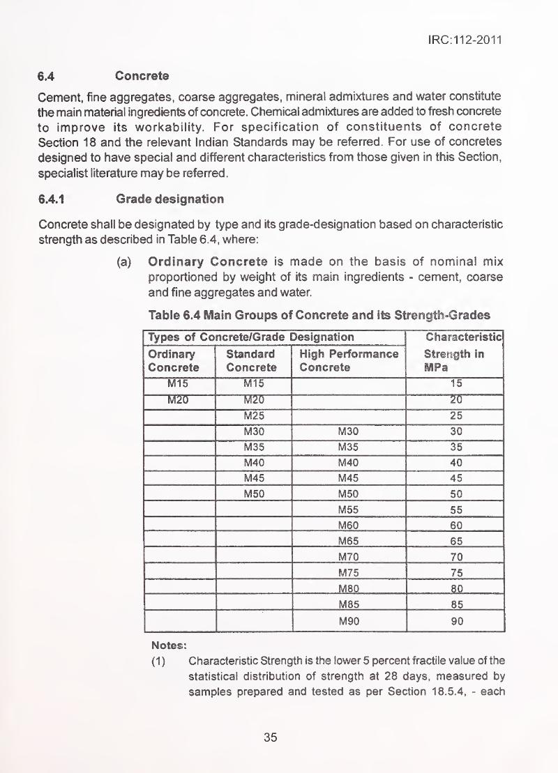
(a) Ordinary Concrete is made on the basis of nominal mix
proportioned by weight of its main ingredients - cement, coarse
and fine aggregates and water.
Table 6.4 Main Groups of Concrete and its Strength-Grades
Types of Concrete/Grade Designation Characteristic
Strength in
IMPa
Ordinary
ConcreteStandard
ConcreteHigh PerformanceConcrete
M15 M15 15
M20 M20 ?D1
M25 25
M30 M30 30
M35 M35 35
M40 M40 40
M45 M45 45
M50 M50 50
M55 55
M60 60
M65 65
M70 70
M75 75
M80 L ^.0
M85 85
M90 90
Notes:
(1 ) Characteristic Strength Is the lower 5 percent tractile value of the
statistical distribution of strength at 28 days, measured by
samples prepared and tested as per Section 18.5.4, - each
35
IRC:112-2011
sample consisting of 3 cubes of 150 mm size.
The grade designation is the nearest lower limit of the range in
multiple of 5 MPa within which the actual characteristic strength
falls.
(2) For concretes using mineral admixtures and those using high
early strength cements, the properties of setting time and time-
dependent strength gain are different from those of standard and
ordinary concrete. Cognisance of such modified properties should
be taken in deciding de-shuttering time, curing period
and early age loading.
(3) Use of Strength other than 28 days Strength:
Actual strength achievable (or achieved) at other than 28 days
strength, but not at more than 84 days in case of slow setting
concretes, can be chosen to base the design/construction
choices, if found more appropriate. This decision should
be based on achievement of early/delayed strength, and the age
at which the first design load, apart from the self-weight, is
expected to be resisted by the structure.
(b) Standard Concrete is made on the basis of design mix proportioned
by weight of its ingredients, which in addition to cement, aggregates
and water, may contain chemical admixtures to achieve certain target
values of various properties in fresh condition, achievement of which
is monitored and controlled during production by suitable tests.
Generally, concretes up to strength Grade M50 are included in
this type.
(c) High Performance Concrete is similar to standard concrete but
contains additional one or more mineral admixtures providing
binding characteristics and partly acting as inert filler material which
increase its strength, reduce its porosity and modify its other
properties in fresh as well as hardened condition. Concretes upto
Grade M90 are included in this type.
6.4.2 Design properties of concrete
6.4.2.1 General
(1) The recommended design properties are co-related to 28 days -
characteristic compressive strength, unless specified otherwise.
(2) Depending on the purpose of analysis, some of the properties are
used either at their mean (average) value, or at lower
characteristic value or at upper characteristic value based on
5 percent fractile or 95 percent fractile respectively.
36
IRC:112=2011
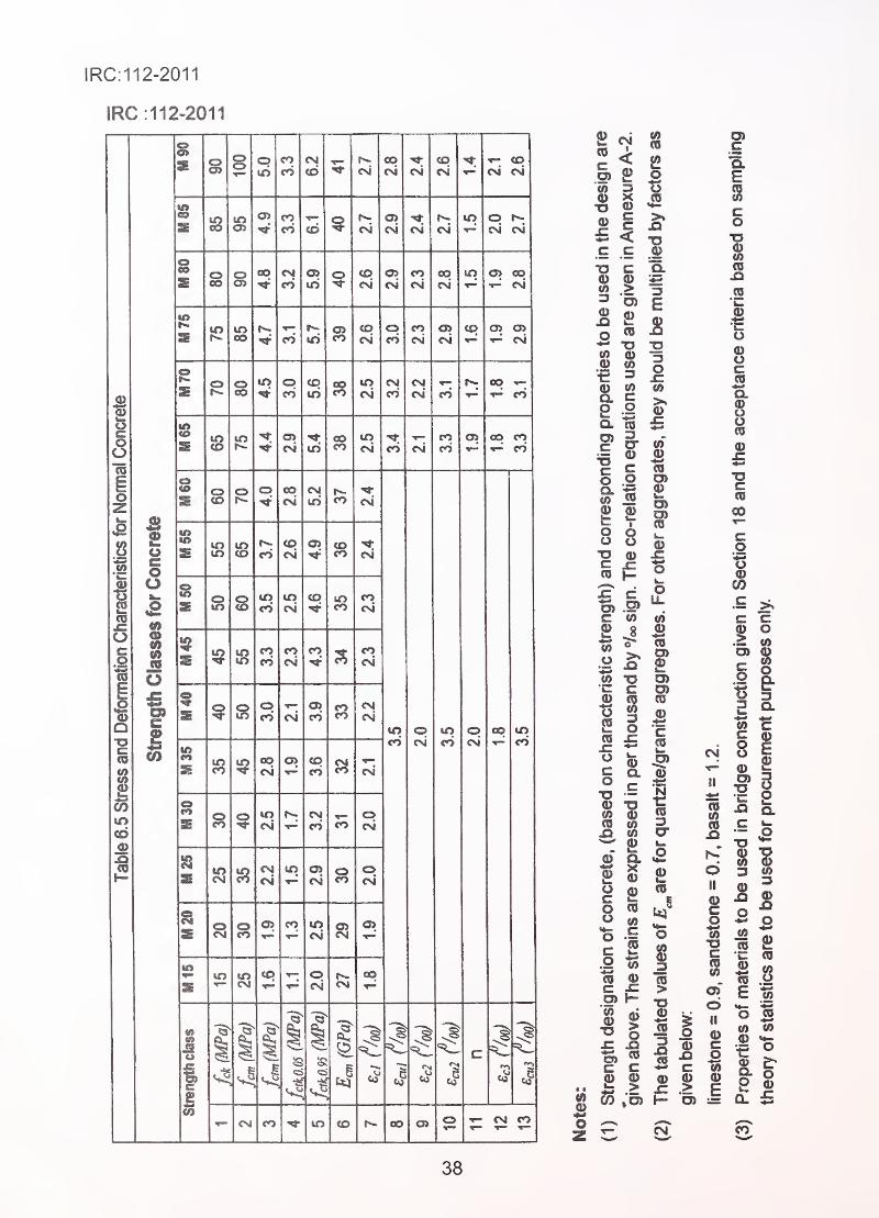
(3) Stress-strain relationship for overall analysis of structure, stress-
strain relationship for sectional design, various moduli of elasticity,
Poisson's ratio, tensile strength, fracture mechanical strength, multi-
axial strengths, etc., are the mechanical properties needed for
various purposes of design. Unless greater accuracy is needed
justifying separate and direct testing for these characteristics, the
values given in Table 6.5 may be used in design, which are based
on their relation to the compressive strength. The co-relation
equations are given in AnnexureA-2.
(4) Some of the time-dependent behaviours of structure and time
dependent effects are permitted to be evaluated by using simplified
expressions, using appropriately modified values of someproperties, (e.g. factored value of the modulus of elasticity to
incorporate creep effects). Where greater accuracy is needed,
specialist literature or relevant intemational codes may be referred.
(5) Relationship between Strength and Time:
The development of compressive strength of concrete depends
on the type of cement, curing conditions and maturity of concrete.
Maturity is measured as a sum of the product of time and mean
temperature of concrete, measured in appropriate units as given
below:
Maturity in day Celsius or hour Celsius = I time in days (or hours) x
(temperature in '»C+11°C). Eq. 6.1
In normal applications instead of the exact strength-maturity
relationship simplified strength-time relationship is used, with limits
of validity as given in Clasue 6.4.2.2. For special applications,
where temperature history deviates from the limits given,
AnnexureA-2 may be referred.
Compressive strength and strength development with time
(1) Relationship connecting age in days to strength given by Eq. 6.2
and Eq. 6.3 can be used in place of strength-maturity
relationship.which are valid for seasonal variation of temperature
between (-)20X to (+)40X.
37
IRC:112-2011
IRC:112-2011
I
in
I
ss
ie
s
Ss
s
I
8 8
8
!8
8
CM
to
CO
to
i
If}
CO
52.
CO
CM
CM
CM
SO
CM
COCM
CO CM
CO
to
T- COCM CM
o r«-
CM csi
a> COtr-" csi
^ CM
«o
OO CO^ CO
5
T- CM CO
38
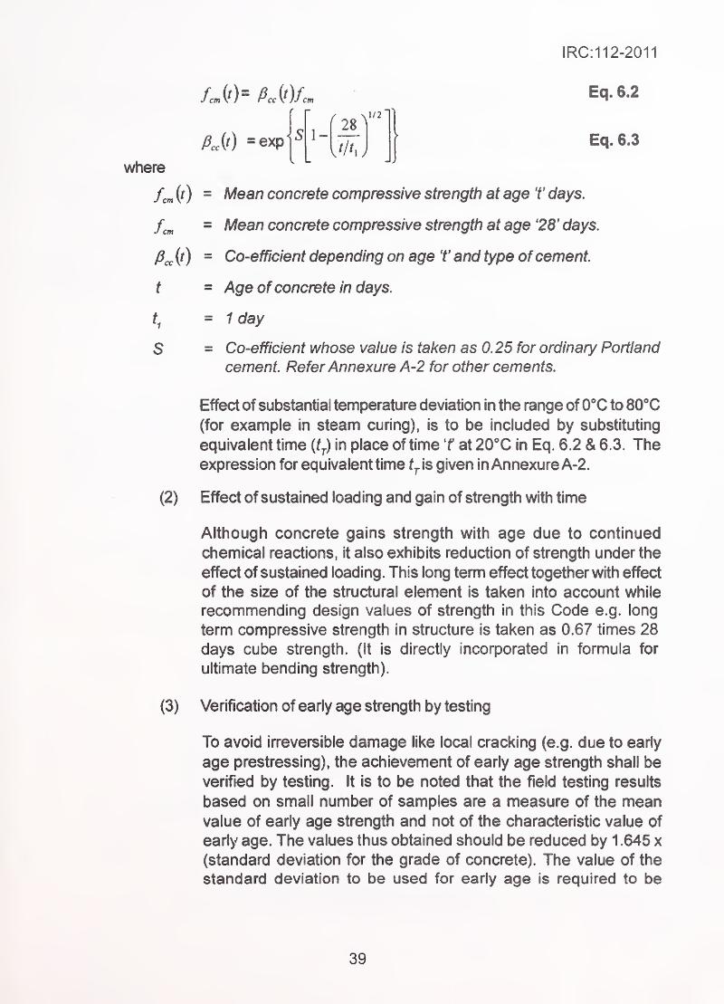
fijt) =exp
where
1/2"
1- >
>
IRC:112-2011
Eq. 6.2
Eq.6.3
fern id ~ Mean concrete compressive strength at age T days.
= Mean concrete compressive strength at age '28' days,
p^(t) = Co-efficient depending on age T and type ofcement
t = Age of concrete in days.
" 1 dayt.1
S = Co-efficient whose value is taken as 0. 25 for ordinary Portland
cement. ReferAnnexure A-2 for other cements.
Effect of substantial temperature deviation in the range of 0*'C to 80*'C
(for example in steam curing), is to be included by substituting
equivalent time (g in place of time T at 20X in Eq. 6.2 & 6.3. Theexpression for equivalent time tj. is given in Annexure A-2.
(2) Effect of sustained loading and gain of strength with time
Although concrete gains strength with age due to continued
chemical reactions, it also exhibits reduction of strength under the
effect of sustained loading . This long term effect together with effect
of the size of the structural element is taken into account while
recommending design values of strength in this Code e.g. long
term compressive strength in structure is taken as 0.67 times 28
days cube strength. (It is directly incorporated in formula for
ultimate bending strength).
(3) Verification of early age strength by testing
To avoid irreversible damage like local cracking (e.g. due to early
age prestressing), the achievement of early age strength shall be
verified by testing. It is to be noted that the field testing results
based on small number of samples are a measure of the meanvalue of early age strength and not of the characteristic value of
early age. The values thus obtained should be reduced by 1 .645 x
(standard deviation for the grade of concrete). The value of the
standard deviation to be used for early age is required to be
39
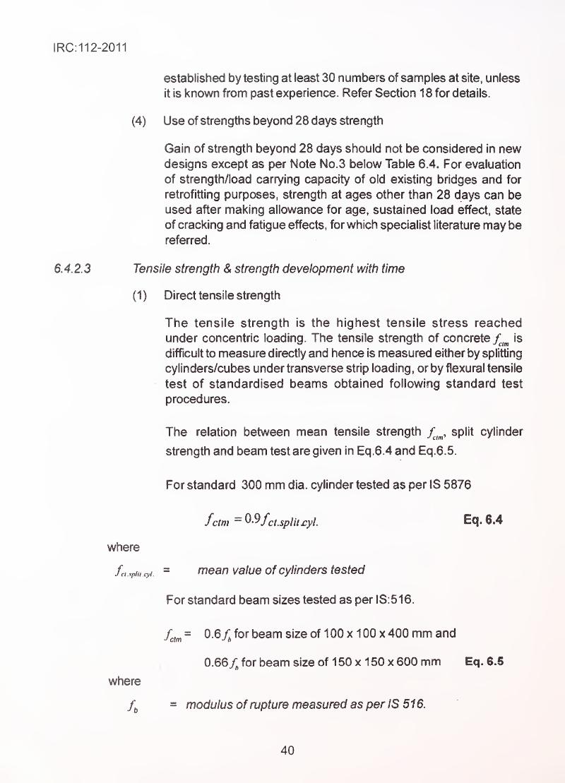
IRC:112-2011
established by testing at least 30 numbers of samples at site, unless
it is known from past experience. Refer Section 1 8 for details.
(4) Use of strengths beyond 28 days strength
Gain of strength beyond 28 days should not be considered in newdesigns except as per Note No.3 below Table 6.4. For evaluation
of strength/load carrying capacity of old existing bridges and for
retrofitting purposes, strength at ages other than 28 days can be
used after making allowance for age, sustained load effect, state
of cracking and fatigue effects, for which specialist literature may be
referred.
6.4.2.3 Tensile strength & strength development with time
(1) Direct tensile strength
The tensile strength is the highest tensile stress reached
under concentric loading. The tensile strength of concrete f^^^ is
difficult to measure directly and hence is measured either by splitting
cylinders/cubes under transverse strip loading, or by fiexural tensile
test of standardised beams obtained following standard test
procedures.
The relation between mean tensile strength split cylinder
strength and beam test are given in Eq.6.4 and Eq.6.5.
For standard 300 mm dia. cylinder tested as per IS 5876
fctm - ^'^fcuplitryl. 6.4
= mean value of cylinders tested
For standard beam sizes tested as per IS:516.
fctm- 0.6/^ for beam size of 100x100 x 400 mm and
0.66/^ for beam size of 1 50 x 1 50 x 600 mm Eq. 6.5
= modulus of rupture measured as per IS 516.
where
fci .xplii .cyl
.
where
40
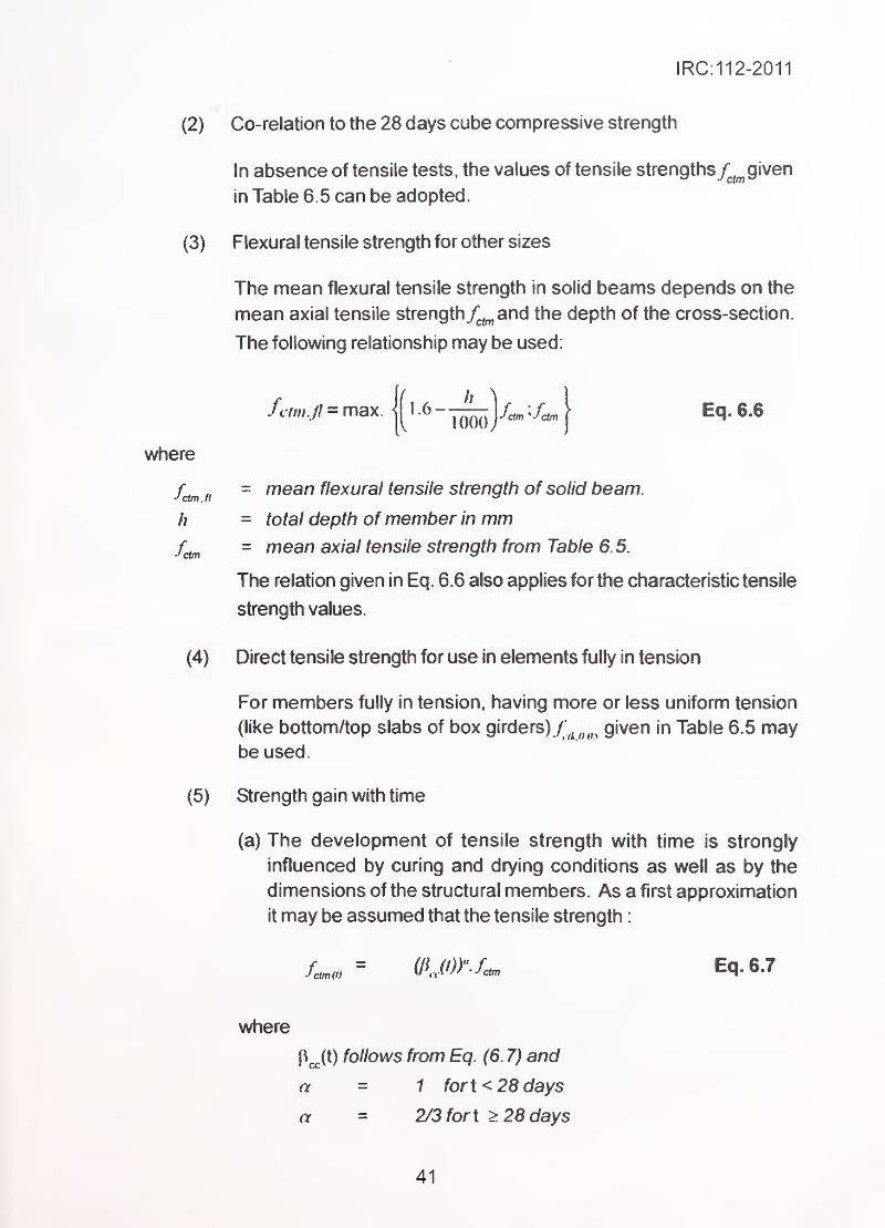
IRC:112-2011
(2)
(3)
where
fctmjl
h
f(Am
(4)
(5)
Co-relation to the 28 days cube compressive strength
In absence of tensile tests, the values of tensile strengthsy^^ given
in Table 6.5 can be adopted.
Flexural tensile strength for other sizes
The mean flexural tensile strength in solid beams depends on the
mean axial tensile strength and the depth of the cross-section.
The following relationship may be used.
= mean flexural tensile strength of solid beam.
= total depth of member in mm- mean axial tensile strength from Table 6.5.
The relation given in Eq. 6.6 also applies for the characteristic tensile
strength values.
Direct tensile strength for use in elements fully in tension
For members fully in tension, having more or less uniform tension
(like bottom/top slabs of box girders)y^^^^,^,^
given in Table 6.5 maybe used.
Strength gain with time
(a) The development of tensile strength with time is strongly
influenced by curing and drying conditions as well as by the
dimensions of the structural members. As a first approximation
it may be assumed that the tensile strength
:
(/UO)''fcctm Eq. 6.7
where
p^(t) follows from Eq. (6. 7) and
a = 1 fort < 28 days
a - 2/3 fort > 28 days
41
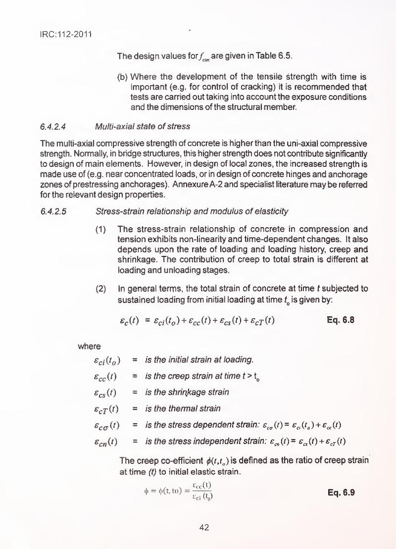
IRC:112-2011
The design values for^^ are given in Table 6.5.
(b) Where the development of the tensile strength with time is
important (e.g. for control of cracking) it is recommended that
tests are earned out taking into account the exposure conditions
and the dimensions of the structural member.
6.4.2.4 Multhaxiaf state of stress
The multi-axial compressive strength of concrete is higher than the uni-axial compressive
strength. Normally, in bridge structures, this higher strength does not contribute significantly
to design of main elements. However, in design of local zones, the increased strength is
made use of (e.g. near concentrated loads, or in design of concrete hinges and anchorage
zones ofprestressing anchorages). AnnexureA-2 and specialist literature may be refenred
for the relevant design properties.
6. 4. 2.5 Stress-strain relationship and modulus of elasticity
(1) The stress-strain relationship of concrete in compression andtension exhibits non-linearity and time-dependent changes. It also
depends upon the rate of loading and loading history, creep andshrinkage. The contribution of creep to total strain is different at
loading and unloading stages.
(2) In general terms, the total strain of concrete at time t subjected to
sustained loading from initial loading at time t^ is given by:
=%fe) + ^cc(0 + ^c5(0 + ^cr(0 Eq.6.8
where
= is the initial strain at loading.
= is the creep strain at time t>t^
= is the shririkage strain
= is the thermal strain
= is the stress dependent strain: s,^ (/) =
^c«(0 = is the stress independent strain: e„ (/)
The creep co-efficient ^{tjj 's defined as the ratio of creep strain
at time (t) to initial elastic strain.
£rc(t)
42
IRC:112-2011
The shrinkage & creep strains are to be estimated as given in
Clauses 6.4.2.6 and 6.4.2.7.
However, for the purpose of analysis of overall structure under
normal temperature variations and its response to loads for static,
equivalent static or linear dynamic response to earthquake loads,
approximate simplified values given in this Code are adequate.
Where greater accuracy is desired and for non-linear elastic analysis
Annexure-A2 and specialist literature should be referred.
The load-deformation characteristics of structure are dependent
on duration of load, age at loading and stress level up to which the
material of the structure is loaded. These are calculated by use of
appropriate modulus of elasticity as under:
(i) For static and quasi-static loads acting for short duration, secant
modulus of elasticity of concrete (slope of line connecting
the origin to stress/strain diagram to 0.33f^J may be used.
Values of E^^ are given in Table 6.5 for different grades of
concrete.
(ti) The Poisson's ratio for uncracked concrete may be taken as
0.2 and that for cracked concrete as zero.
(iii) In general, the effects of long term loading (due to creep) shall
be obtained separately and added to those obtained from short
temi analysis. As a simplification for the overall analysis of
structure (not for local analysis), the value ofE_ can be modified
by a factor accounting for long term creep effects where
^ is the creep co-efficient defined by Eq. 6.9 and Table 6.9.
(iv) For calculating creep effects of shorter duration, either separate
analysis should be done or can be modified by factor
consistent with the creep of the same duration.
(v) The effect of shrinkage shall be separately calculated and
added. It is taken as part of dead load analysis.
(vi) For calculating effects of seasonal temperature variation, value
of 0.5 times may be used to account for temperature induced
stresses as modified by creep effects.
43
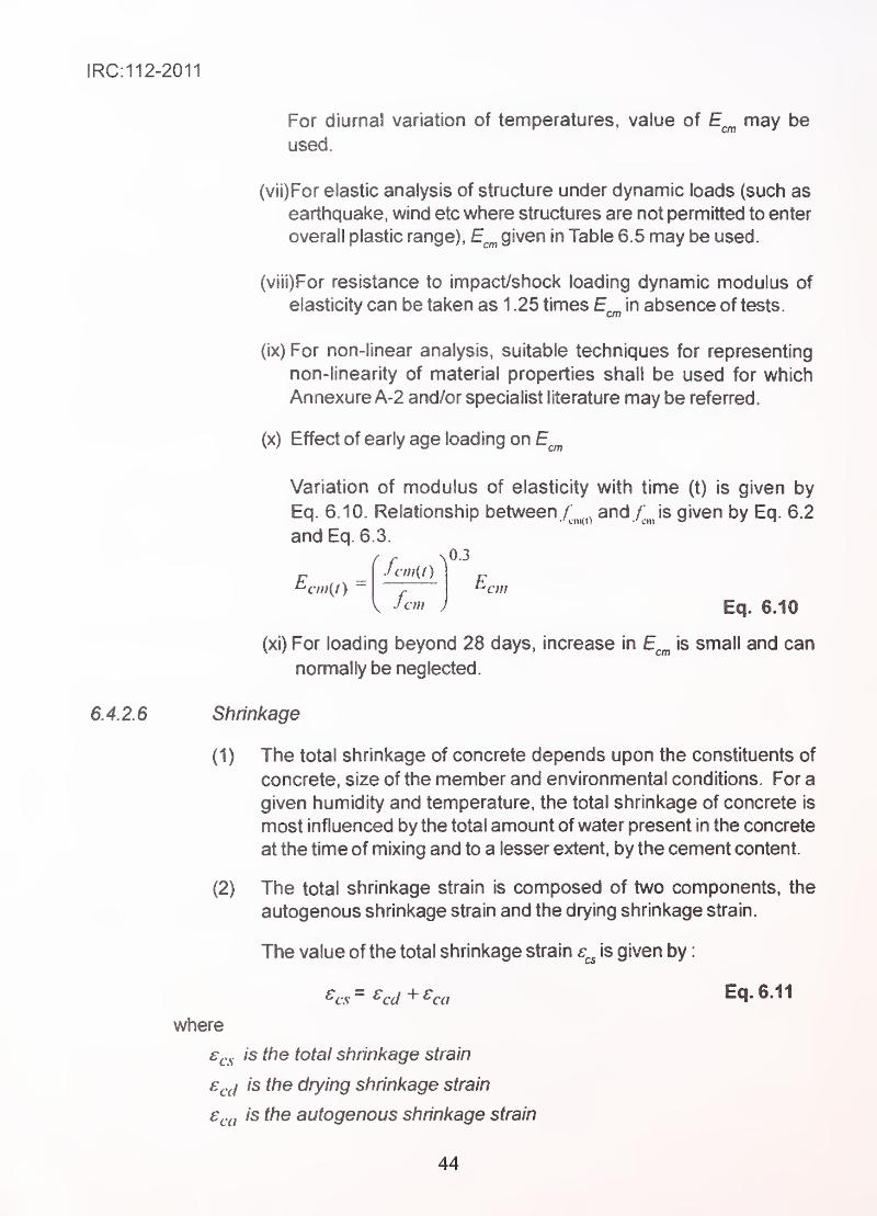
For diurna! variation of temperatures, value of E^^ may be
used. --
(vii)For elastic analysis of structure under dynamic loads (such as
earthquake, wind etc where structures are not permitted to enter
overall plastic range), E^^ given in Table 6.5 may be used.
(viii)For resistance to impact/shock loading dynamic modulus of
elasticity can be taken as 1 .25 times E in absence of tests.
(ix) For non-linear analysis, suitable techniques for representing
non-linearity of material properties shall be used for which
Annexure A-2 and/or specialist literature may be referred.
(x) Effect of early age loading on E^^
Variation of modulus of elasticity with time (t) is given by
Eq. 6.10. Relationship between /".^^^^^ and /"^Js given by Eq. 6.2
and Eq.6.3.
(xi) For loading beyond 28 days, increase in E^^ is small and can
normally be neglected.
Shrinkage
(1) The total shrinkage of concrete depends upon the constituents of
concrete, size of the member and environmental conditions. For a
given humidity and temperature, the total shrinkage of concrete is
most influenced by the total amount of water present in the concrete
at the time of mixing and to a lesser extent, by the cement content.
(2) The total shrinkage strain is composed of two components, the
autogenous shrinkage strain and the drying shrinkage strain.
The value of the total shrinkage strain is given by
:
E,cm{l)- E,cm
Eq. 6J0
^cs ^cd ca Eq. 6.11
where
£f.^is the total shrinkage strain
£^.j is the drying shrinkage strain
€^.^1 is the autogenous shrinkage strain
44
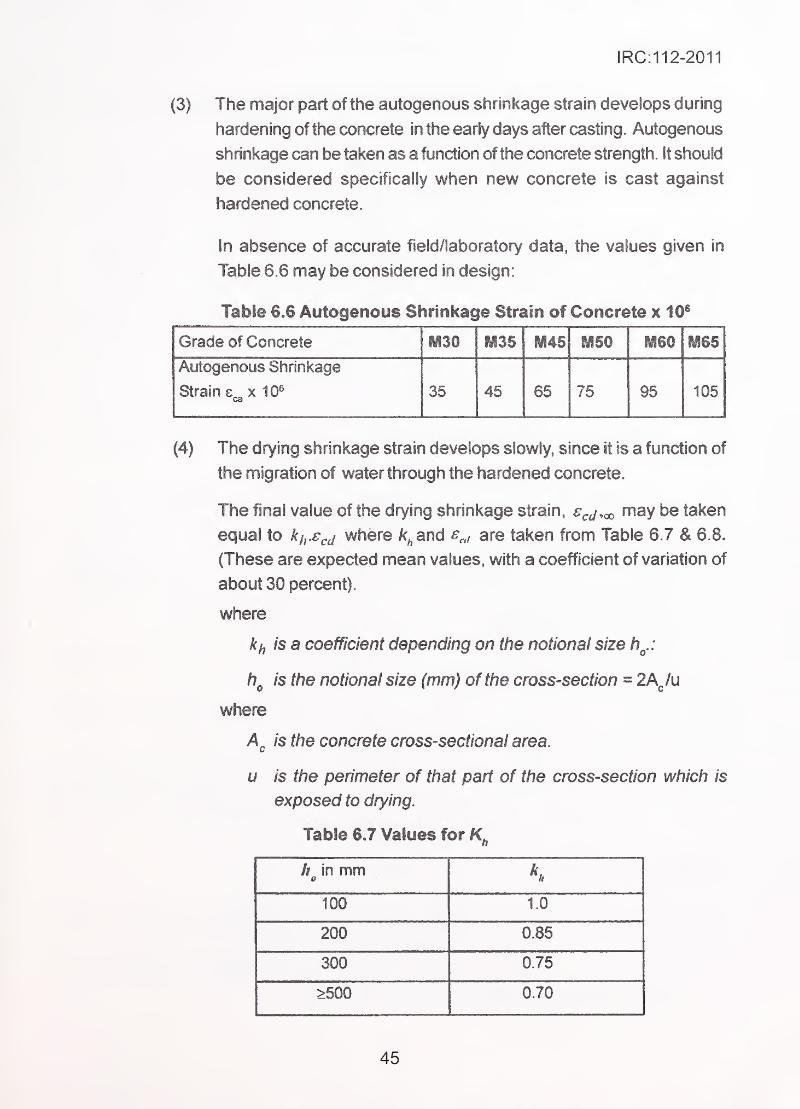
IRC:112-2011
(3) The major part of the autogenous shrinkage strain develops during
hardening of the concrete in the early days after casting. Autogenous
shrinkage can be taken as a function of the concrete strength. It should
be considered specifically when new concrete is cast against
. hardened concrete.
In absence of accurate field/laboratory data, the values given in
Table 6.6 may be considered in design:
Table 6,6 Autogenous Shrinkage Strain of Concrete x 10®
Grade of Concrete mm M35 ii45 HUSO ii60 fyiss
Autogenous Shrinkage
Strain e x 10®ca
35 45 65 75 95 105
(4) The drying shrinkage strain develops slowly, since it is a function of
the migration of water through the hardened concrete.
The final value of the drying shrinkage strain, s^j.ao be taken
equal to i/jX^j where k^and £,,1 are taken from Table 6.7 & 6.8,
(These are expected mean values, with a coefficient of variation of
about 30 percent).
where
is a coefficient depending on the notional size h^.:
is the notional size (mm) of the cross-section = 2AJu
where
is the concrete cross-sectional area.
u is the perimeter of that part of the cross-section which is
exposed to drying.
Table 6.7 Values for
is in mm
100 10
200 0.85
300 0.75
>500 0.70
45
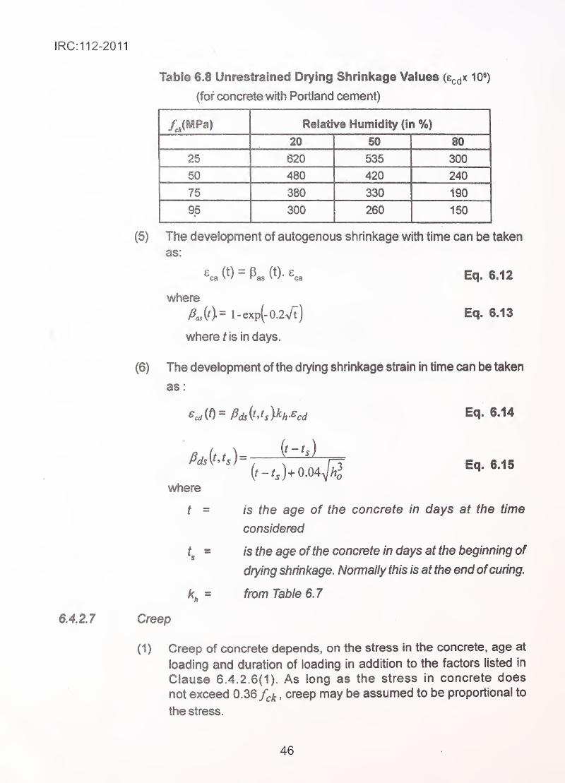
IRC:112-2011
6.4.2.7
(5)
Table 6.8 Unrestrained Drying Shrinkage Values (Scd^ iO^)
(for concrete with Portland cement)
fJMPa) Relative Humidity (in %)
20 50 80
25 620 535 300
50 480 420 240
76 380 330 190
95•
300 260 150
The development of autogenous shrinkage with time can be taken
as:
as ca
where
fiM^ l-exp(-0.2Vt)
where f is in days.
Eq. 6.12
Eq. 6.13
(6) The development of the drying shrinkage strain in time can be taken
as
Eq. 6.14
Eq. 6.15
where
t = is the age of the concrete in days at the time
considered
is the age ofthe concrete in days at the beginning of
drying shrinkage. Normally this is at the end ofcuring.
from Table 6. 7 '
,
Creep
(1) Creep of concrete depends, on the stress in the concrete, age at
loading and duration of loading in addition to the factors listed in
Clause 6.4.2.6(1). As long as the stress in concrete does
not exceed 0.36 /^^ ,creep may be assumed to be proportional to
the stress.
46
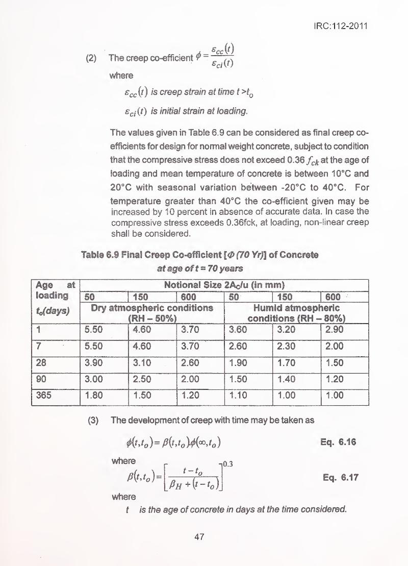
IRC:112-2011
1 ^cc(2) The creep co-efficient 9 -
where
s^c (t) is creep strain at time t >iQ
Edit) is initial strain at loading.
The values given in Table 6.9 can be considered as final creep co-
efficients for design for nomial weight concrete, subject to condition
that the compressive stress does not exceed 0.36 f^k at the age of
loading and mean temperature of concrete is between WC and
20X with seasonal variation between -20''C to 40X. For
temperature greater than 40X the co-efficient given may beincreased by 10 percent in absence of accurate data. In case the
compressive stress exceeds 0.36fck, at loading, non-iinear creep
shall be considered.
Table 6.9 Final Creep Co-efflcient [0(70 Yr)] of Concrete
at age of f = 70 years
Age at
loading
to(days)
Notional Size 2Ac/u (in mm)50 1 150 600 50 150 600Dry atmosplieric conditions
(RH - 50%)Humid atmospheric
conditions (RH-80%)1 5.50 4.60 3.70 3.60 3.20 2.90
7 .
•
5.50 4.60 3.70 2.60 2.30 2.00
28 3.90 3.10 2.60 1.90 1.70 1.50
90 3.00 2.50 2.00 1.60 1.40 1.20
365 180 150 i 1.20 1.10 1.00 1.00
(3) The development of creep with time may be taken as
^itjJ=fi(^Jo)4M Eq. 6.16
where
where
0.3
Eq. 6.17
t is the age ofconcrete in days at the time considered.
47
IRC:112-2011
is the age of concrete in days at time of loading.
(t- tj is the actual duration of loading in days.
fi,f is a coefficient depending on the relative humidity (RH
in percent) and the notional member size {h^ in mm).
It may be estimated from:
Rll=l.5|l + (!.2 )"^j/^, + 250< 1500 for/^<45 Eq.6.18
RllPu = I 511 + (1 .2—)"' 1 /;„ + 250a < 1 500«for^>45 Eq. 6.19
where
Rfi = Relative humidity expressed as percent.
Rll,, = 100 (i.e. 100 percent)
a = is coefficient to consider the influence of the
concrete strength:
6.4.2.8
(4)
a45
cm
05
Eq.6.20
in MPa
Where 45 and /[.„, in numerator has units of MPa.
h
A.
Notional size ofmember in mm =2A.
II
= Cross Sectional Area in mnf.
u = Pehmeter in contact with atmosphere in mm.
Where greater accuracy is required in estimating (p(t,tj Annexure
A-2 and/or the specialist literature may be referred.
Stress-strain relation for design of sections
(1) Uncorifineci concrete ''
.
(a) Parabolic rectangular stress-strain block
For design of section, the following relationship may be used
as shown in Fig.6.5.
48
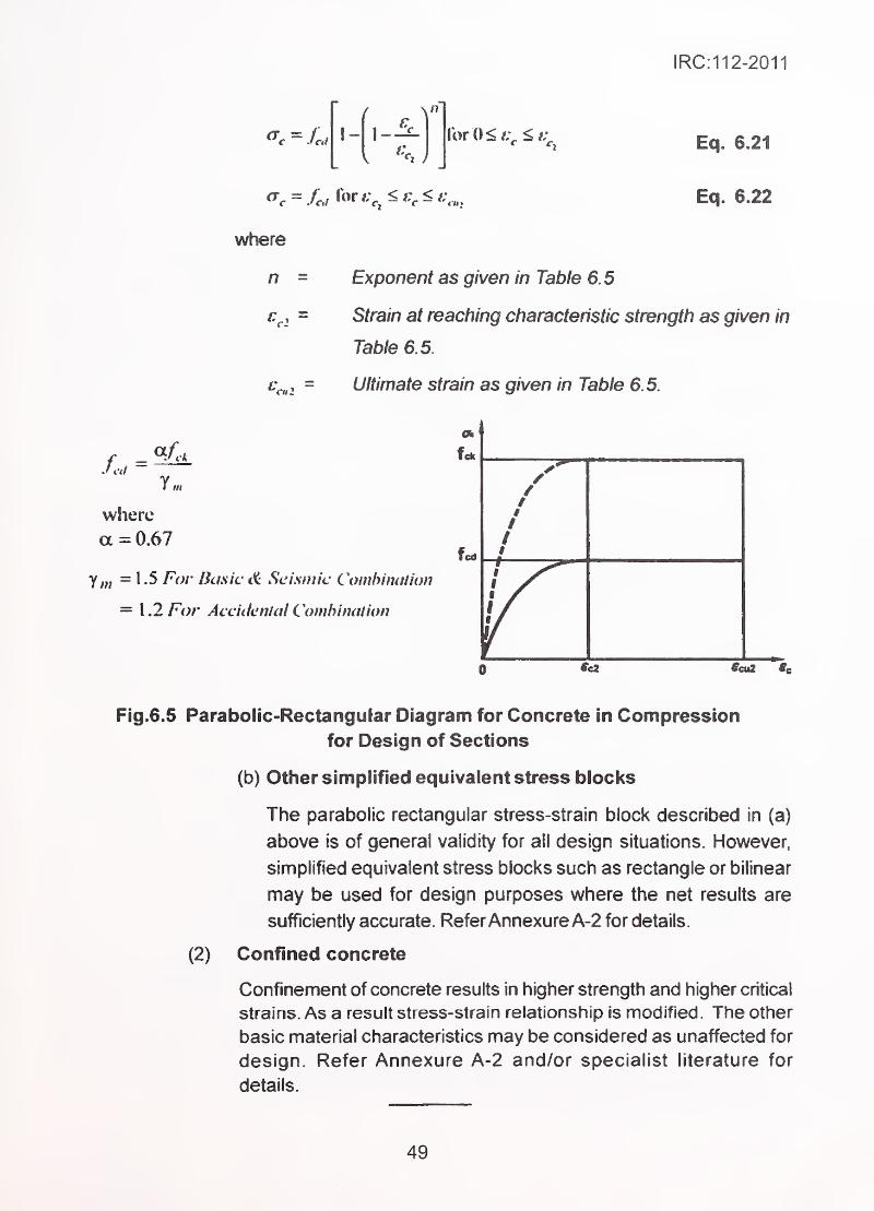
IRC:112-2011
where
Ec|. 6.21
Eq. 6.22
^c2=
Exponent as given in Table 6.5
Strain at reaching characteristic strength as given in
Table 6.5.
Ultimate strain as given in Table 6.5.
Li =1m
where
a =0.67
y„, =1.5 For Bcmc^ Seismic Comhimition
= \ .2For Acciikntal Combination
Fig.6.5 Parabolic-Rectangular Diagram for Concrete in Compression
for Design of Sections
(b) Other simplified equivalent stress blocks
The parabolic rectangular stress-strain block described in (a)
above is of general validity for all design situations. However,
simplified equivalent stress blocks such as rectangle or bilinear
may be used for design purposes where the net results are
sufficiently accurate. ReferAnnexure A-2 for details.
(2) Confined concrete
Confinement of concrete results in higher strength and higher critical
strains. As a result stress-strain relationship is modified. The other
basic material characteristics may be considered as unaffected for
design. Refer Annexure A-2 and/or specialist literature for
details.
49
IRC:112-2011
SECTION 7 ANALYSIS
7.1 General Provisions
7.1.1 Response ofstrucium to loads
The purpose of structural analysis is the verification of overall stability and establishment
of action effects on the whole or a part of the structure. These effects include the
distribution of internal forces and moments as well as the calculation of stresses, strains,
curvatures, rotations and displacements in static or dynamic modes. To carry out analysis,
the geometry, boundary conditions and behaviour ofthe stmcture will need to be idealized
both for global and local behaviour. The structure is idealised by considering it as madeup of elements which can be linear, two dimensional or three dimensional. Classical
methods of mechanics or modern techniques such as finite element can be used for
analysis depending upon the suitability of the mathematical model to evaluate the action
effects with sufficient accuracy.
Since concrete is a heterogeneous material, its properties are not independent of the
size of the member. These are also time dependent. For reinforced and prestressed
concrete elements the structural behaviour depends on the location and amount of
steel as well as the state of deformation and cracking ofthe element, which in turn, depends
upon the level of load. In the analysis, appropriate simplified values of properties of
constituent materials and properties representing composite action (e.g. bond) are madein order to represent the behaviour ofthese elements. The range of validity ofthese simplified
properties and the level of accuracy in predicting the structural behaviour by analytical
methods, has to be taken into account in the design process.
The in-service behaviour of structural elements as well as their ultimate strengths
and modes of failure are determined by the material properties, load resisting
mechanism of the structural elements and the combined effect of axial forces,
bending moments, transverse shears, in-plane shears and torsions. Theinterdependency of various strengths of a member; such as axial, bending, shear
and torsion, has been established both by theory and by experiments. However,
in most cases of practical design, bending combined with axial forces and sh0ar
combined with torsion are treated separately. In this approach, the design models
used in different load resisting mechanisms are not completely compatible.
Design of columns, beams and slabs are typically based on this approach. For
elements having complex geometry - such as shells - and for some local zones
of the elements (refer Clause 7.1.2.2) design has to be based on the net effect of
all forces acting together, ensuring compatibility of strains. Suitable model
representing the element and appropriate method of analysis have to be used
in the design process.
50

IRC:112-2011
7J .2 Methods of analyses
7.1.2.1 General
In terms of the behaviour of the structure, the following methods of analysis may be
used:
(1 ) Linear elastic analyses for both static and dynamic response
(2) Linear elastic analyses with limited redistribution of forces for static
response
(3) The 'Strut and Tie* method for achieving intemai equilibrium within
the elements in conjunction with overall elastic analysis
of the stnjcture, where stiffness of the structural elements is based
on assumptions (a) or (b) as described in Clause 7.2(1).
(4) Non-linear analyses, (material and/or geometric non-iinearity) for
both static and dynamic response
The solutions based on failure mechanisms of structure or plastic
behaviour of elements shall not be used in design of bridges; except
for the case of analysing response to earthquake. This shall be
done only after adequate investigation of all significant modes of
failure.
in addition to global analyses of structure or its components, local analyses may be
necessary, particularly where.
(1 ) Significant and rapid changes in stresses and strains in a particular
region of the structure/component are involved (e.g. regions around
openings, junctions of elements).
(2) Local non-linear behaviour needs to be analysed, (e.g. locally near
supports/bearings, formation of hinges).
(3) Assumption of linear strain distribution is not valid, (e.g. thick
sections, deep beams, corbels, anchorage zones).
Where local effects are calculated separately, independent of global effects, the effects
shall be combined.
(1 ) Second order effects are the additional effects caused by structural
defomnations, e.g. P-A effect for column.
7.1.2.2 Local analyses
7JJ Second order effects
51
IRC:112-2011
(2) Second order effects shall be considered in the analysis where
they are likely to affect overall stability or the attainment of the
ultimate limit state at critical sections, (e.g. buckling of slender
members, redistribution of forces due to creep of concrete,
settlement of supports in indeterminate structure).
7.1.4 Modelling of foundations
Structural elements transferring toads to the foundation strata can be treated as rigid or
flexible depending on their stiffness with appropriate end conditions. Settlement effects
are to be treated as independent loading conditions. Where soil-structure interaction is
considered as significantly influencing the behaviour of the structure, the foundation and
stratum shall be appropriately modelled (e g by use of appropriate springs)
7.1.5 Redistribution of moments
Redistribution of moments obtained by rigorous elastic analysis may be carried out
provided;
(1) Reduction at one location is accompanied by increase in other
location in such a way as to maintain equilibrium with applied
loads.
(2) Reduction is restricted to not more than 1 5 percent of the maximummoment in SLS and 20 percent of that in ULS.
Redistribution shall not be carried out in circumstances where the rotation capacity and
the section to which the redistributed moments are to be transferred, cannot be defined
(e.g. in curved bridges and skew bridges with more than 1 5° angle of skew).
7.1.6 Non-linear analyses
Non-linearity of material stress-strain relationship is taken into account for design of sections.
Non-linearity arising from member's response (e.g. due to cracking, creep etc.) is
considered in calculating the deflections.
Non-linearity due to formation of plastic hinges in linear members or yield lines in two
dimensional elements, is not permitted except for demonstrating non-collapse condition
in seismic event or impact loading.
7.1.7 Plastic analysis
(1) Methods based on lower bound plastic solutions may be used
provided appropriate measures are taken to ensure that ductility
conditions are satisfied.
52
IRC:112-2011
(2) Elements may be idealised as statically determinate trusses
consisting of straight notional struts (carrying the compressive forces
in the concrete) and ties (the reinforcement). The forces in the
members of the truss are established from considerations of
equilibrium. Sufficient reinforcement is then provided to carry the
tension in the ties and a check is performed to ensure that the
compressive stresses in the struts are not excessive. Detailing
requirements should then be checked, with particular regard to
anchorage of all reinforcement and to local bearing stresses due to
concentrated forces.
(3) The location and orientation of the struts and ties should reflect
approximately the distribution of internal forces resulting from anelastic analysis of the member
<4) In checking compressive stresses in the struts, consideration should
be given to a possible reduction in strength due to transverse tensile
stresses or cracking or the influence of shear. The average design
compressive stress in the struts may be taken as v.f^^ . In the
absence of other data, v may be taken as 0.6, including an allowance
for sustained loading. Higher values for v (even v>A) may be justified
based on a triaxial state of compressive stress, provided it can be
shown that the complementary transverse compression can berealised in practice.
(5)' The design stress in the ties is limited to /'
,.
(6) Detailing should comply with Sections 1 5 & 1 6.
Analyses for Serviceability Limit States
(1) Elastic methods of analysis should be used to determine internal
forces and deformations. The stiffness constants of discrete
members or unit widths of slab elements may be based on any of
the following:
(a) Concrete Section: The entire cross-section of member, ignohng
the presence of reinforcement.
(b) Gross Transformed Section: The entire cross-section of memberincluding the reinforcement transformed on the basis of
effective modular ratio, —1—eff
A consistent approach should be used to reflect the behaviour
of various parts of the structure.
53
(2) For limit state checks of deformation, stresses and crack control of
beams having wide compression flanges, a constant effective width
should be used over the full span while working out the sectional
properties. (Refer Clause 7.6.1.2). Where greater accuracy is
required variation in the effective width along the spans should be
considered.
(3) Modulus of elasticity and shear modulus of concrete should be
appropriate for the type of action under consideration.
(4) For verification of steel stresses and control of cracks in discontinuity
zones, strut-and-tie model as adopted in the ULS design may be
used.
Analyses for Ultimate Limit States
(1) Elastic methods may be used to determine the distribution of forces
and deformations throughout the structure. Stiffness constants
based on the section properties as used for the analysis of the
structure at the serviceability limit state, may be used in the analysis.
(2) In seismic analysis, plastic method of analysis may be used
provided it can be shown that adequate ductility exists at
sections/locations where successive hinges/yield lines form andthese methods adequately model the global effects in
combination with local plasticity.
(3) The application of elastic methods of analysis for factored loads
for the ultimate limit state in general leads to safe lower bound
solutions. These may be refined and made more accurate and less
conservative. For suitable methods, specialist literature may be
(4) For longitudinal members effects due to temperature gradient may
be neglected.
(5) Strut-and-tie model may be used in the analysis of discontinuity
regions. Struts representing compressive stress field and ties
provided by reinforcement, meet at connecting nodes fonning
statically stable truss system. The reinforcement carries full design
force of the tie over its full length and hence is required to be
adequately anchored beyond the node. Adoption of model
developed on the basis of stress trajectories in compression and
54
IRC:112-2011
tensile regions established from linear elastic analysis or following
direct and simple load path method, should be preferred as it will
help in achieving crack control at serviceability conditions. Specialist
literature may be referred for details.
7.4 Torsional Effects
7.4.1 Where static equilibrium of a structure depends on the torsional resistance
of its elements, full torsional design covering ULS shall be made.
7.4.2 In general, where the torsional resistance or stiffness of members has not
been taken into account in the analysis of the structure, no specific calculations for resisting
torsion will be necessary. In such cases adequate control of any torsional cracking should
be achieved by providing nominal reinforcement to resist torsion. However, in applying
this clause it is essential that sound engineering judgement is exercised in deciding whether
torsion plays only a minor role in the behaviour of the structure; otherwise torsional stiffness
should be used in the analysis.
7.6 Combined Global and Local Effects
In addition to the design of individual elements to resist loading applied directly to them, it
is also necessary to consider the loading effects due to global loading where these coexist
in an element.
Analysis of the structure may be accomplished either by one overall analysis or by separate
analyses for global and local effects. In the latter case, the forces and moments acting on
the element from global and local effects should be combined as appropriate. The design
of individual elements should take into account the combined effects.
7,6 Structures and Structural Frames
7.6.1 Beams
7.6.1.1 Effective span
(1 ) The effective span of a simply supported member should be taken
as the smaller of:
(a) The distance between the centres of bearings,
(b) The clear distance between supports plus the effective depth.
(2) The effective span of a member framing into supporting membersshould be taken as the distance between the centres of the
supporting members.
(3) The effective span of a continuous member should be taken as the
distance between centres of supports.
55
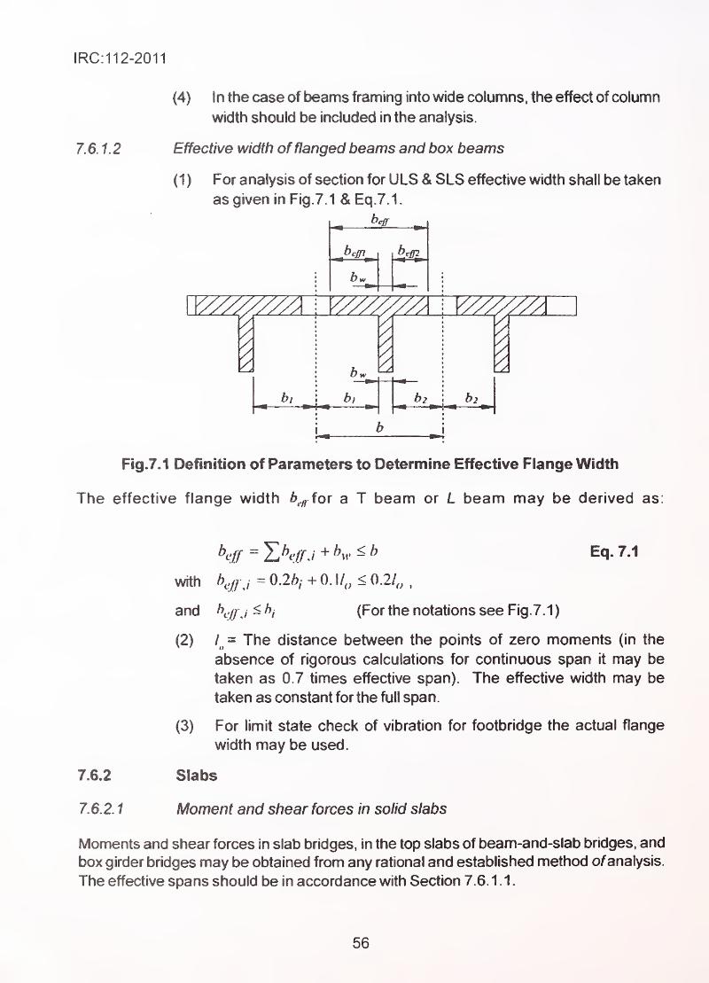
IRC:112-2011
7.6.1.2
(4) In the case of beams framing into wide columns, the effect of column
width should be included in the analysis.
Effective width offlanged beams and box beams
(1 ) For analysis of section for ULS & SLS effective width shall be taken
as given in Fig. 7.1 & Eq.7.1.
_ heir
21
b2
'A
Fig.7.1 Definition of Parameters to Determine Effective Flange Width
The effective flange width 6.^ for a T beam or L beam may be derived as:
7.6.2
7.6.2. t
KlJ = YuKffA +K ^ ^ Eq. 7.1
with />,^/,, =0.2i^, +0.l/,,<0.2/,,
and h^jj , < hj (For the notations see Fig.7. 1
)
(2) = The distance between the points of zero moments (in the
absence of rigorous calculations for continuous span it may be
taken as 0.7 times effective span). The effective width may be
taken as constant for the full span.
(3) For limit state check of vibration for footbridge the actual flange
width may be used.
Slabs
Moment and shear forces in solid slabs
Moments and shear forces in slab bridges, In the top slabs of beam-and-slab bridges, and
box girder bridges may be obtained from any rational and established method ofanalysis.
The effective spans should be in accordance with Section 7.6. 1.1.
56
IRC:112-2011
7.6.2.2 Special types of slabs
For analysis of special type of slabs such as skew slab, curved slabs, voided slabs and
composite slabs, specialist literature may be referred.
7.6.3 Columns
7.6.3.1 Definitions
A reinforced concrete column is a compression member whose largest lateral cross-
sectional dimension is less than or equal to four times its lesser lateral dimension.
A column should be considered as short if the ratio 4 / i in each plane of buckling is
such that the failure takes place without involving secondary effects. In practice, the
limits upto which the secondary effects can be neglected is given in Clause 11.2.
7.6.3.2 Moments and forces in columns
(1 ) The moments, shear forces and axial forces in a column should be
determined in accordance with Clauses 7.2 and 7.3. except that if
the column Is slender the additional moments Induced by lateral
deflection should be considered. The bases and/or other membersconnected to the ends of such columns should also be designed to
resist these additional moments.
(2) In columns with moments it is generally sufficient to consider the
maximum and minimum ratios of moment/axial load in designing
reinforcement areas and concrete sections.
7. 6. 3. 3 Buckling of columns and overall structure
For rules regarding verification of safety against buckling, refer Section 1 1 .0.
7.6.4 Reinforced concrete walls
7.6.4.1 Definition.
A wall is a vertical load bearing concrete member whose larger lateral dimension is more
than four times its lesser lateral dimension. A wall may be considered as short where the
ratio of its effective length (height) to its thickness does not exceed 12. It should othenA^ise
be considered as slender. Retaining walls, wing walls, abutments and other similar wall-
like elements where ultimate axial load is less than 0.1^.^^^. may be designed as bending
elements, neglecting axial load.
57
IRC:112-2011
7.6.42 Forces and moments in reinforced concrete walls
Forces and moments should be calculated in accordance with Clauses 7.2 and/or 7.3
except that if the wail is slender, the moments induced by deflection should also be
considered. The distribution of axial and horizontal forces along a wall from the loads on
the superstructure, should be determined by the type and location of the supports. For
walls integral with deck, the moments/forces should be detemnined by elastic analysis.
The design moment per unit length in the direction at right angles to a wall should be not
less than 0.06 nji, where is the ultimate axial load per unit length, Q.OSh is the nominal
minimum eccentricity and h is the thickness of the wall. Moment in the plane of a wall can
be calculated from statical equilibrium required for the most severe positioning ofthe relevant
loads.
Where the concentrated load is acting on a wall, dispersal of loads within the length and
height of the wall shall be considered.
It will generally be sufficient to consider the maximum and minimum ratios of moment to
axial load in designing reinforcement areas and concrete sections.
7.7 Composite Concrete Construction.
'-
'
'
71A General .,
(1) These recommendatiojis apply to flexural members consisting of
precast concrete units acting In conjunction with cast-ln-situ
concrete, where provision has been made for the transfer of
horizontal shear at the contact surface. The precast units may be
of either reinforced or prestressed concrete.
(2) Differential shrinkage and creep of the component concrete
members requires consideration in analysing composite members
for the serviceability limit states. Differentia! shrinkage and creep
need not be considered for the ultimate limit state.
(3) In general, the analysis and design of composite concrete structures
and their component members should be in accordance with the
principle defined earlier except that effects of differential shrinkage
and creep should be treated as a primary action. Particular attention
should be given in the design of the component parts and the
composite section to take into account the effect on stresses and
deflections arising out of the method of construction (e.g. whether
props are used or not used).
58
IRC:112-2011
(4) A check for adequacy of components/whole section should be madefor each stage of construction. The relative stiffness of membersshould be based on the concrete or gross transformed section
properties as described in Clause 7.2. If the -concrete strengths of
the two components of the composite member differ by more than
10N/mm^, allowance for the difference in modulus of elasticity should
be made in assessing stiffness and stresses.
(5) When at least one of the components is a prestressed member,the combined effect of shrinkage and creep movements of the
prestressed member(s) with respect to other member(s) create time-
dependent variation of stresses, which may be more severe at
intermediate stages leading to tensile cracking. The time
dependent properties of shrinkage and creep given in Section 6
should be used in this evaluation.
(6) When only the shrinkage effects are involved, it is sufficient to
analyse for the maximum value of differential shrinkage.
7.7.2 Continuity of spans in composite construction
When continuity is obtained in composite construction by changing the statical system,
consideration should be given to the secondary effects of differential shrinkage and creep
on the moments in continuous beams and on the reactions at the supports.
7.7.2.1_
Effect ofdifferential shrinkage
The hogging restraint moment, at an internal support of a continuous composite beamand slab section due to differential shrinkage should be taken as:
„ •„ M,^={s,J(E^}AjS,Ja . Eq. 7.2
where
€^0- is the differential shrinkage strain; • :
Ecf is the modulus of elasticity of the flange concrete;
Acf is the area of the effective concrete flange;
Seem the distance of the centroid of the concrete flange fromthe centroid of the composite section;
a is a reduction coefficient to allow for creep
« = (^-^'")'*Eq.7.3
7.7.2.2 Creep redistribution due to dead load and prestress in the precast
unit
When a concrete structure's statical system is changed during construction, creep ofthe
concrete will modify the as-built bending moments (and shear forces) towards the
59
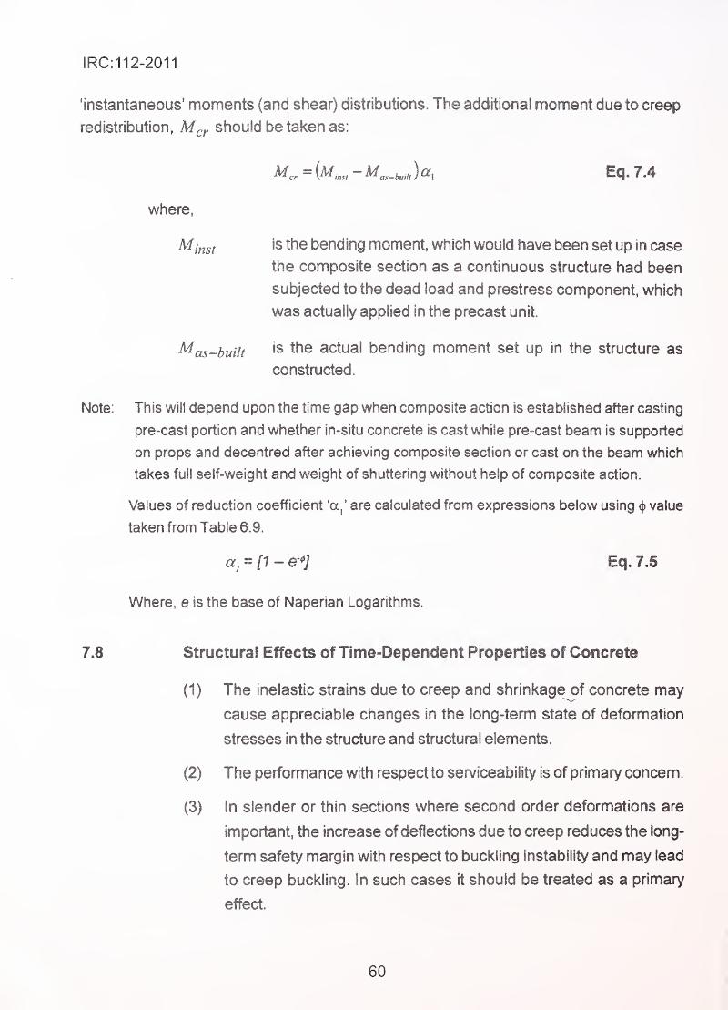
!RC:112-2011
'instantaneous' moments (and shear) distributions. The additional moment due to creep
redistribution, M^,. should be taken as:
where,
^inst is the bending moment, which would have been set up in case
the composite section as a continuous structure had been
subjected to the dead load and prestress component, which
was actually applied in the precast unit.
^as-built is the actual bending moment set up in the structure as
constructed.
Note: This will depend upon the time gap when composite action is established after casting
pre-cast portion and whether in-situ concrete is cast while pre-cast beam is supported
on props and decentred after achieving composite section or cast on the beam which
takes full self-weight and weight of shuttering without help of composite action.
Values of reduction coefficient 'a,' are caiculated from expressions below using ^ value
taken from Table 6.9.
a^ = 11- e-^] Eq. 7.6
Where, e is the base of Naperian Logarithms.
7.8 Structural Effects of Time-Dependent Properties of Concrete
(1) The inelastic strains due to creep and shrinkage of concrete may
cause appreciable changes in the long-term state of deformation
stresses in the structure and structural elements.
(2) The perfomiance with respect to serviceability is of primary concern.
(3) In slender or thin sections where second order deformations are
important, the increase of deflections due to creep reduces the long-
term safety margin with respect to buckling instability and may lead
to creep buckling. In such cases it should be treated as a primary
effect.
60
!RC:112-2011
(4) Shrinkage and creep act in a complex interdependent way. The
creep of concrete reduces internal stresses induced by shrinkage.
Where great accuracy is not required, this effect can be directly
. evaluated by using reduced value of modulus of elasticity of concrete
[approx. E^^/ (1+^) refer Section 6] which corresponds to
the stresses caused by the imposed strains.
(5) The restrained thermal stresses arising from seasonal variation in
• temperatures are similarly reduced by creep and can be directly
evaluated by reduced E value of 0.5 times E .
^ cm
(6) For purpose of analysis of creep and shrinkage treated as acting
independently, time-dependent properties of concrete and relaxation
of steel given in Section 6 can be used.
Prestressing force applied by pre-tensioned steel or by post-tensioned steel and transferred
to the structure througii bond between steel and concrete or through mechanical
anchorages, is covered in this Section.
(1) Prestressing is considered as an action and its effect should be
included in the forces/moments and applied to the structure.
(2) Prestressing force is time-dependent. Its magnitude also varies from
the intended value due to technological reasons. Both the effects
should be considered in selection of design prestressing force.
(3) The contribution of prestressing tendons to the resistance developed
by the member shall be limited to the additional forces mobilised
by their further deformation, consistent with the ultimate deformation
of the member.
(1) The maximum force applied to tendon at active end during
tensioning, shall not exceed 90 percent of 0.1 percent proof load
(or proof-stress).
(2) In exceptional conditions temporary overstressing during stressing
operation is permitted up to 95 percent of 0.1 percent of proof load
7.9 Prestressed Members and Structures
7.9.1 General
7.9.2 Maximum prestressing force
61
IRC:112-2011
(or proof stress), provided that the accuracy of measurement is
ensured to be within ±5 percent.
(3) Maximum prestressing force applied to structure immediately
after transfer (i.e. after losses due to elastic shortening and
anchorage slip) shall not be greater than 75 percent of/, or 0.85 of
0.1 percent proof load whichever is less (Refer Fig.6.3).
7.9.3 Loss of prestress, ,
7.9.3.1 Immediate losses in pre-tensioning
The foilowing losses occurring during pre-tensioning shall be considered:
(1) During the stressing process:
Loss due to friction at the bends (in the case of curved wires and
strands) and losses due to wedge draw-in of the anchorage devices.
(2) Before the transfer of prestress to concrete: ;
Loss due to relaxation of the pre-tensioning tendons during the
period between the tensioning of tendons and release of the same
for transfer of prestress.
Note: In case of steam curing, losses due to shrinkage and relaxation are modified and
should be assessed accordingly. Annexure-2 and/or specialist literature may be referred.
Direct thermal effect on prestressing steel should also be considered.
(3) At the transfer of prestress to concrete; ^-•
-
(a) Loss due to elastic deformation of concrete.
(b) Loss due to d raw-in of tendon at two ends of concrete member,
taking into account favourable/u nfavou rable bond condition.
7. 9. 3.2 Immediate losses ofprestress in post-tensioning
(1 ) Losses due to the elastic deformation of concrete
Loss in tendon force corresponding to elastic shortening of
concrete at the level of tendon shall be taken into account. The order
in which the tendons are stressed shall be considered for calculation
of loss.
62
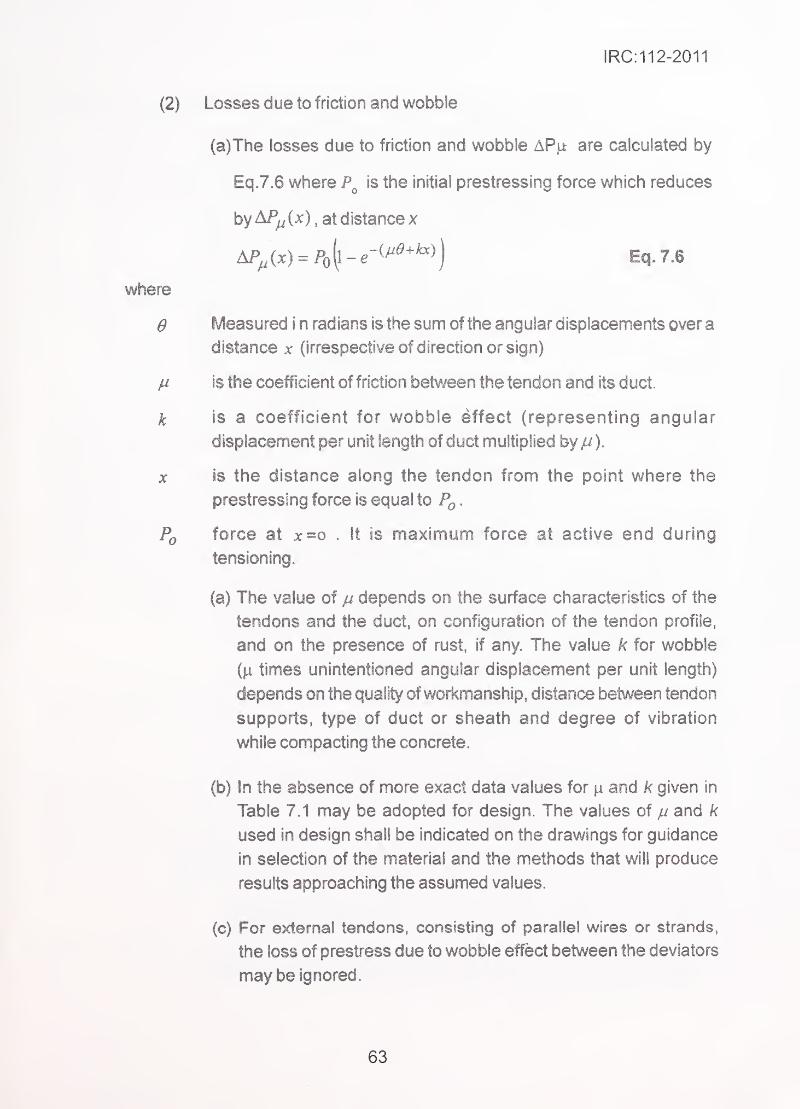
IRC:112-2011
where
e
k
X
Po
Losses due to friction and wobble'
(a)The losses due to friction and wobble AP|i are calculated by
Eq.7.6 where is the initial prestressing force which reduces
by AP,^ (x), at distance x
Measured i n radians is the sum of the angular displacements over a
distance x (irrespective of direction or sign)
is the coefficient of friction between the tendon and its duct.
is a coefficient for wobble effect (representing angular
displacement per unit length of duct multiplied by // ).
IS the distance along the tendon from the point where the
prestressing force is equal to .
force at x=o . It is maximum force at active end during
tensioning.
(a) The value of ju depends on the surface characteristics of the
tendons and the duct, on configuration of the tendon profile,
and on the presence of rust, if any. The value k for wobble
(|i times unintentioned angular displacement per unit length)
depends on the quality ofworkmanship, distance between tendon
supports, type of duct or sheath and degree of vibration
while compacting the concrete.
(b) In the absence of more exact data values for ^ and k given in
Table 7.1 may be adopted for design. The values of ju and k
used in design shall be indicated on the drawings for guidance
in selection of the material and the methods that will produce
results approaching the assumed values.
(c) For external tendons, consisting of parallel wires or strands,
the loss of prestress due to wobble effect between the deviators
may be ignored.
Eq. 7.6
63
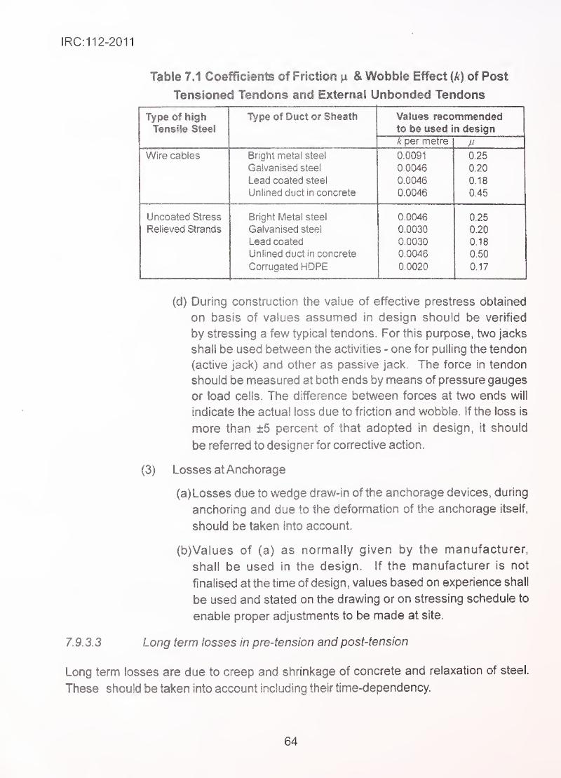
!RC:112-2011
Table 7.1 Coefficients of Friction n & Wobble Effect {k) of Post
Tensioned Tendons and External Unbonded Tendons
lype OT nign Values recommendedto be used in design
k oer metre
Wire cables Bright metal steel 0.0091 0.25
Galvanised steel 0.0046 0.20
Lead coated steel 0.0046 0.18
Unlined duct in concrete 0 0046 0.45
Uncoated Stress Bright Metal steel 00046 0.25
Relieved Strands Galvanised steel 0.0030 0 20
Lead coated 0.0030 0.18
Unlined duct in concrete 0.0046 0.50
Corrugated HOPE 0.0020 0.17
(d) During construction the value of effective prestress obtained
on basis of values assumed in design should be verified
by stressing a few typical tendons. For this purpose, two jacks
shall be used between the activities - one for pulling the tendon
(active jack) and other as passive jack. The force in tendon
should be measured at both ends by means of pressure gauges
or load cells. The difference between forces at two ends will
indicate the actual loss due to friction and wobble. If the loss is
more than ±5 percent of that adopted in design, it should
be referred to designer for corrective action. ^
.
(3) Losses atAnchorage
(a) Losses due to wedge draw- in of the anchorage devices, during
anchoring and due to the deformation of the anchorage itself,
should be taken into account.
(b)Vaiues of (a) as normally given by the manufacturer,
shall be used in the design. If the manufacturer is not
finalised at the time of design, values based on experience shall
be used and stated on the drawing or on stressing schedule to
enable proper adjustments to be made at site.
1.9.3.2 Long term tosses in pre-tension and post-tension
Long term losses are due to creep and shrinkage of concrete and relaxation of steel.
These should be taken into account including their time-dependency
64
IRC:112-2011
7.9.4 Consideration of prestress in analysis
(1) For linear analysis both the primary and secondary effects of
prestressing shall be applied.
(2) Full bond between steel and concrete may be assumed after
grouting of bonded tendons. However, before grouting, the tendons
shall be considered as unbonded.
(3) External tendons may be assumed to be straight between deviators.
7.9.5 Partial factors for prestressing force
(1 ) Prestress in most situations, is intended to be favourable. However,
under some load combinations the effect may becomeunfavourable.
(2) In case of bonded tendons, for ultimate limit state of strength, the
design value of prestressing force shall be based on the mean
.
value acting at that time, with partial factor = 1
.
(3) In case of unbonded tendons and external tendons, the stress
increase in ultimate limit state of strength may be calculated taking
into account the overall deformation of the member. If no such
calculations are made, the increase in stress in prestressing tendon
shall be taken as nil, and partial factor /p = 1
.
(4) Where external/unbonded tendons are used for achieving stability
and where decrease of force or increase of force becomes
unfavourable for stability, partial factors of 0.8 and 1.25 shall be
used to decrease or increase the force, as required.
Note: These factors account for the possible adverse variation in
prestressing force. This shall be over and above the overall safety
factors against overturning and sliding required for global stability
checks.
(5) In verification of local effects Yp.unfay = 1 shall be used.
(6) In serviceability limit state, two characteristic values of prestressing
force shall be used.
^Lsup = Xsup.Pm.(/)(^) EQ- 7.7
65
IRC:112-2011
Pk.M =rM.Pmin(^), ^
' Eq.7J
where ' -
(x) is effective prestressing force at point 'x' at time 'f and ^k.sup and
jnf are corresponding superior and inferior characteristic values. The
values of /sup and /j^f shall be as follows:
for pre-tensioning or unbonded tendons ^'sup =1 05 and /j^f= 0.95.
for post-tensioning with bonded tendons fsup =1 .10 and /j^f= 0.9.
7.9.6 Part prestressing of tendon
The requirement of minimum concrete strength behind the anchorage of post
tensioned system, at the time of stressing, for full jacking force, designated as f Jshall be specified by the designer taking into account special requirements of the
structure, if any, and the recommendations of the manufacturer of prestressing
system.
If any individual tendon is stressed in stages before the specified strength f^^str of concrete
is achieved, the relation between the stage stressing and specified minimum strength
shall be as follows:
For 100% jacking force, minimum concrete strength is fc,str
For 30% ofjacking force, minimum concrete strength = 0.5 f^^^
Between 30% and 100% of jacking force, minimum concrete strength
shall be arrived at by linear interpolation between 0.5 f^ str & fcstr •
7.10 Design and Detailing for Curved Tendons in Thin Sections
7.10.1 Radial pressure from curved tendons
The curved tendons exert radial pressure on concrete. This introduces local compression
on inner side of the curvature and tension on outer side of curvature in the plane of the
tendon. When this pressure acts on thick sections with large cover to ducts or in plane of
the member, the normal reinforcement provided for shear or surface reinforcement is
adequate to control any cracking in this region.
For tendons provided in thin curved sections (like webs curved in plan or curved slabs of
box sections) pressure acting outwards from the plane of the member causes local out-of-
plane punching shear as well as overall bending and shear in the curved members. The
following additional checks shall be carried out in such situations.
66
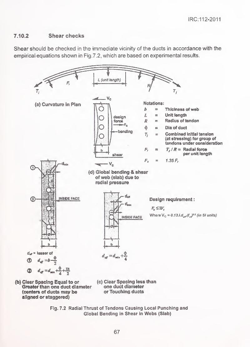
IRC:112-2011
7.10.2 Shear checks
Shear should be checked in the immediate vicinity of the ducts in accordance with the
empirical equations shown in Fig. 7. 2, which are based on experimental results.
fa| Cuwature in Plan Notafionsi
b -
L '
R '
Tj
Fa
fd| Global bending & shearof web (slab} due to
radial pressure
TliiciisM of w«bUniteigtti
Radiys of tendon
DIaof duct
Coifibifi«d inllai tension
fat s^Mingl for group of
tendons undor coftsidoFBtion
Tj/R^ Radial fofeoper unit tongtti
t35F,
Design requirement i
Where Vc = 0.13.l.d^(fJ°' (in SI units)
(b) Clear Spacing Equal to orGreater ttian one duct diameter(centers of dyds maif bealigned or staggered)
(c) Clear Spacing less thanone duct diameteror Touching ducts
Fig. 7.2 Radial Thrust of Tendons Causing Local Punching andGlobal Bending In Shear In Webs (Slab)
67
IRC:112-2011
7J 0.3 Radial reinforcement ^
The local radial tensions set up in concrete behind radia! thrust of a group of ducts lying in
one plane, introduce de-laminating forces tending to separate concrete on two sides of
the plane of the duct. These tensions should be resisted by reinforcement forming full loops
or 180° hooks (Fig. 15.2(e) with 180* bend) placed in the concrete section connecting
concrete on two sides of plane of ducts. As a simplification, full radial thrust F^(Fig. 7.2)
can be resisted by HYSD reinforcement steel limiting permissible tensile stress to
230 MPa.
7.11 Special Load Transferring Devices
7.11.1 General
Devices like bearings of various types, dislodgement preventing stoppers and shock
transmission units are used to transmit loads between parts of bridge elements. The global
analysis of the structure should include the overall behaviour of these elements In terms of
their load/deformation characteristics in a simplified way, by defining the released and
restrained movements of the structure to which they are connected. However, the design
of these elements themselves shall be based on the details of internal load transferring
mechanism and materials used in their fabrication. '
7.11.2 Grade effect and positioning of bearings
For bridges built in grade or cross-fall, the bearings shall normally be set level by varying
the thickness of the plate situated between the upper face of the bearing and lower face of
the beam or by any other suitable arrangement. However, where the bearings are required
to be set parallel to the inclined grade or cross-fall of the superstructure, an allowance shall
be made for the longitudinal and transverse components of the vertical loads on
the bearings.
68
IRC:112-2011
SECTION 8 ULTIMATE LllilT STATE OF LINEAR ELEMENTS FORBENDING AND AXIAL FORCES
8.1 Scope
(1 ) This Section covers structural members which can be idealised as
linear members having the following characteristics: (a) one of the
dimension (length or height) is sufficiently large as compared to
other two dimensions of its cross-section (breadth, width, thickness),
(b) the cross-sections which were plane before loading remain
approximately plane after loading and loading is such that the
distortion of the section by shear and torsional strains is not large
enough to vitiate this assumption, (c) the regions of geometric
.
•
' discontinuity and heavy transverse loads where the assumption in
, (b) does not hold good locally, form a small part of the total length.
'
,
' (2) Generally, members having length larger than 4 times the largest
linear dimension of cross-section, can be considered to belong to
. this class. Under certain conditions of loading members having
,
' length between 1 to 4 times the cross-sectional dimensions will
'
• % ' qualify for being treated as linear members (e.g. short columns
without bending created by transverse shear).
(3) Ultimate load carrying capacity of predominantly axially loaded
members is adversely affected by instability (buckling) for long
., .•, members by effect of second-order deformations caused by initial
geometric imperfections, unintentional and small eccentricity of
external loads or effect of lateral deflection due to transverse loading
or end fixity conditions (moments). Additional checks for such effects
and design of slender members in general are included in
Section 11.
(4) Simplified methods for bi-axial bending are covered.
(5) Simplified methods for small magnitudes of axial forces acting
together with bending moments are covered.
8.2 Strain and Stress Distribution at Ultimate Limit State
8.2.1 Limitations on strain and stresses
(1) In analysing a cross-section to determine its ultimate resistance,
69
the assumptions given below shall be used: ^
(a) Plane sections remain plane. ''
(b) The strain in bonded reinforcement and in bonded prestressing
steel beyond the initial pre4ension before bonding, whether in
tension or compression, is the same as that in the surrounding
concrete.
(c) The tensile strength of the concrete is ignored.
(d) The stresses in the concrete in compression are derived from
the design stress-strain diagram in Fig. 6.5, which is a parabolic-
rectangular diagram. For other shapes of stress-strain diagram,
referAnnexureA-2. '"
;"
•
(e) The stresses in the reinforcement steel are derived from the
design curves in Fig. 6.2, and the stresses for prestressing steel
are derived from Fig.6.3 or Fig.6.4 as appropriate, after dividing
stresses by partial factor for materials as shown.
(f) When upward sloping branch of stress-strain curve beyond the
linear elastic portion is used, the tensile stresses in reinforcing
and prestressing steel are limited to those corresponding to
strain of 0.9^,,^ . Where idealised plastic branch is used for this
part, of the curve, it is not necessary to check strain limit.
(g) The initial p re-strain introduced in prestressing tendons is taken
into account when assessing the stresses in the tendons at the
ultimate limit state.
(h) For cross-sections subject to pure longitudinal compression,
the compressive strain in the concrete is limited to e^.
( j) For cross-sections subject to axial compressive force and bending
and where neutral axis lies outside the section, the strain at
most compressed face is restricted to z^^. The strain diagram
is defined by assuming that the compressive strain is at a
level (1-8^2^ E^^g) of the height of the section from the most
compressed face.
70
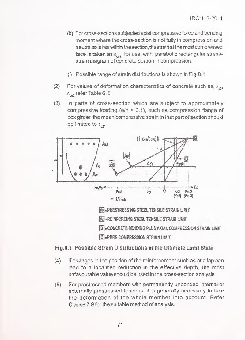
IRC:112-2011
(2)
(3)
(k) For cross-sedions subjeded^ axial compressive for<^ and bending
moment where the cross-section is not fully in compression and
neutralaxis lies within thesection^thestra'inatthe most impressed
face is taken as e^g. for use with parabolic rectangular stress-
strain diagram of concrete portion in compression.
(I) Possible range of strain distributions is shown in Fig. 8. 1
.
For values of deformation characteristics of concrete such as, e^,
£, refer Table 6. 5.CU2
In parts of cross-section which are subject to approximately
compressive loading (e/h < 0.1), such as compression flange of
box girder, the mean compressive strain in that part of section should
be limited to e^^-
m €«2
g^PRESTRESSING STEEL TENSILE STRAIN UilT
S .REINFORCING STEEL TENSILE STRAIN UMIT
[Ij=COHCRETE BENDING PLUS AXIAL COMPRESSION STRAIN UMTT
[cj.PURE COMPRESSION STRAIN UMIT
Fig.8.1 Possible Strain Distributions in the Ultimate Limit State
(4) If changes in the position of the reinforcement such as at a lap can
lead to a localised reduction in the effective depth, the most
unfavourable value should be used in the cross-section analysis.
(5) For prestressed members with permanently unbonded internal or
externally prestressed tendons, It is generally necessary to take
the deformation of the whole member into account. Refer
Clause 7.9 for the suitable method of analysis.
71
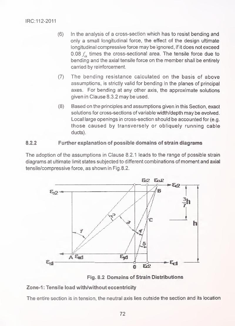
IRC:112-2011
8.2.2
(6) In the analysis of a cross-section which has to resist bending and
only a small longitudinal force, the effect of the design ultimate
longitudinal compressive force may be ignored, if it does not exceed
0.08 times the cross-sectional area. The tensile force due to
bending and the axial tensile force on the member shall be entirely
carried by reinforcement.
(7) The bending resistance calculated on the basis of aboveassumptions, is strictly valid for bending in the planes of principal
axes. For bending at any other axis, the approximate solutions
given in Clause 8.3.2 may be used.
(8) Based on the principles and assumptions given in this Section, exact
solutions for cross-sections of variable width/depth may be evolved.
Local large openings in cross-section should be accounted for (e.g.
those caused by transversely or obliquely running cable
ducts).
Further explanation of possible domains of strain diagrams
The adoption of the assumptions in Clause 8.2.1 leads to the range of possible strain
diagrams at ultimate limit states subjected to different combinations of moment and axial
tensile/compressive force, as shown in Fig. 8.2.
f
•'V
h
0 ^Fig. 8.2 Domains of Strain Distributions
Zone-1 : Tensile load with/without eccentricity
The entire section is in tension, the neutral axis lies outside the section and its location
72
IRC:112-2011
depends on the eccentricity of the tensile force. Reinforcing/prestressing steel at least on
one side yields (with strains limited as per either idealised or simplified diagrams) which
decide the ultimate tensile capacity.
Zone-2: Compressive load with eccentricity, having neutral axis within
Section, and ultimate strength governed by tensile steel
The maximum strain in the concrete is less than the limiting value of V^^^ thus the
strength of the concrete is not exhausted. The tensile strain at steel Is at the upper
design limit of s^^.
Zone-3 : Compressive load with eccentricity, having neutral axis within
section, and steel beyond yield, ultimate strength governed byconcrete
The concrete compression strain at the upper fibre is at upper design limit s^^^. Thesteel strain lies between Sy^i and .
Zone-4 : Compressive load with eccentricity, with ultimate strength governed
by concrete and steel strain is below yield strain.
This is typically the cause of steel strength not fully exploited giving over-reinforced
non-ductile failure.
The boundary between Zone-3 and Zone-4 is called the balanced condition, where
the maximum concrete strain ( ^^^2 ) and reinforcement strain at yield (^yd) are present
simultaneously.
Zone-5: Compressive Ibad with eccentricity, having neutral axis outside the
section (i.e. full section in compression)
The entire section (with exception of possibly existing prestressing steel) is in
compression. AH strain profiles pass through point 0. The maximum compressive strain
of concrete at 0 is between z^^^ O.C lies where the line BO (which
defines the boundary between sections partially in tension and sections in compression)
intersects the vertical line characterized by = constant. The distance of this point
from the outermost compressive fibre is taken as equal to (^-s^z^^cu^^ of the total
depth of the section.
8.3 Biaxial Bending
8.3.1 General solution
The analysis of members of generalised cross-section having irregular shape is not normally
required in bridge design. Methods are available in specialist-literature for members having
73
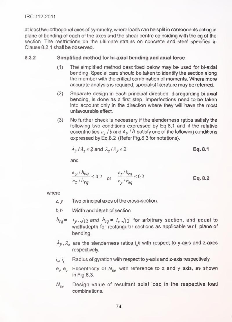
IRC:112-2011
at least two orthogonal axes of symmetry, where loads can be split in components acting in
plane of bending of each of the axes and the shear centre coinciding with the eg of the
section. The restrictions on the ultimate strains on concrete and steel specified in
Clause 8.2.1 shall be observed.
8.3.2 Simplified method for bi-^xial bending and axial force
(1) The simplified method described below may be used for bi-axial
bending. Special care should be taken to identify the section along
the member with the critical combination of moments. Where moreaccurate analysis is required, specialist literature may be referred.
(2) Separate design in each principal direction, disregarding bi-axial
bending, is done as a first step. Imperfections need to be taken
into account only in the direction where they will have the mostunfavourable effect.
(3) No further check Is necessary if the slendemess ratios satisfy the
following two conditions expressed by Eq.8.1 and if the relative
eccentricities e^lb and eyi h satisfy one of the following conditions
expressed by Eq.8.2 (Refer Fig.8.3 for notations).
A_y/A^<2and 4/^_y<2 Eq. 8.1
and ••.
-
where
z,y Two principal axes of the cross-sectbn,
b,h WWth and depth of section
hq" h • Vl2 a^c/ h^q^ /- ^12 ^or arbitrary section, and equal to
width/depth for rectangular sections as applicable w.r.t. plane of
bending.
^y,X2 are the slenderness ratios\J\
with respect to y-axis and z-axes
respectively.
z^,, Radius of gyration with respect to y-axis and z-axis respectively.
Eccentricity of N^^ with reference to z and y axis, as shown
in Fig.8.3.
N^^ Design value of resultant axial load in the respective load
combinations.
74
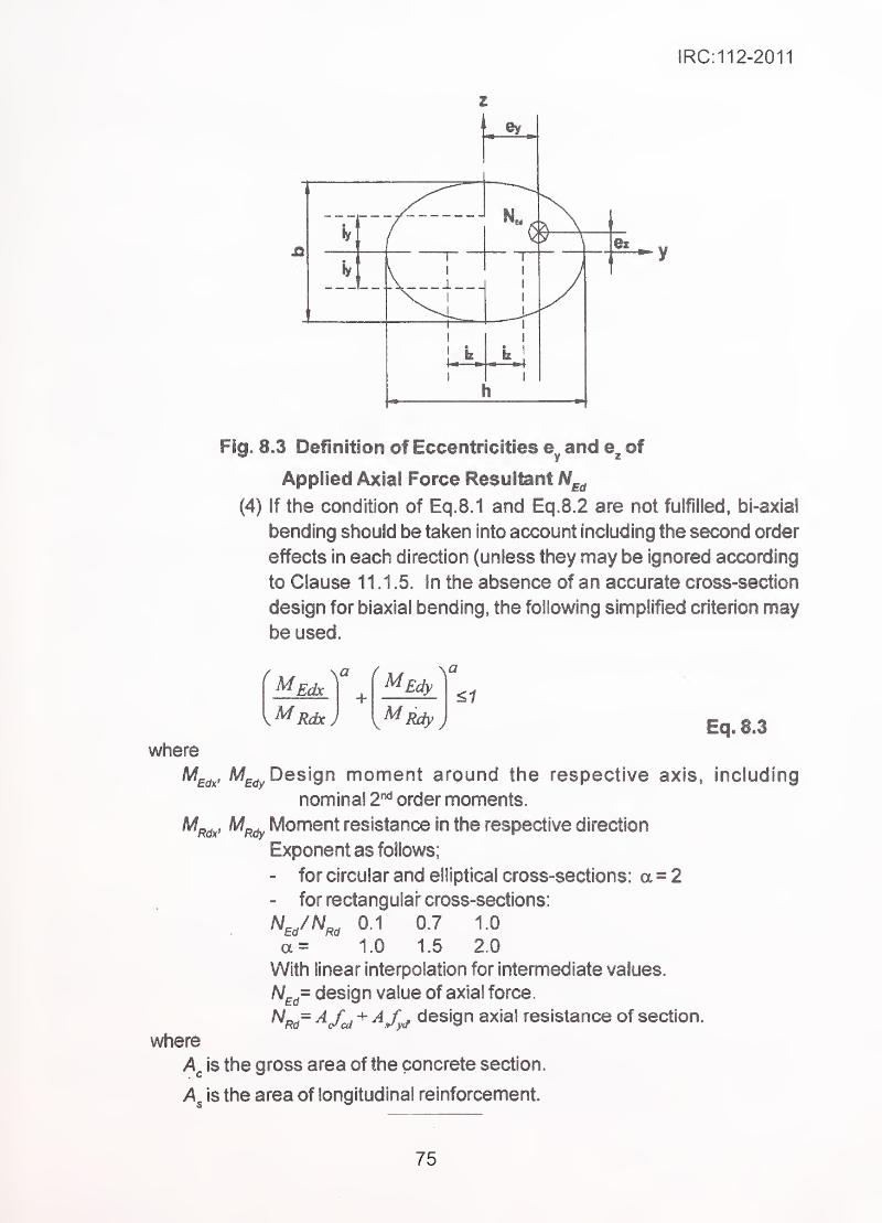
IRC:112-2011
Flg» 8,3 Definition of Eccentricities and of
Applied Axial Force Resultant N^^
(4) If the condition of Eq.8.1 and Eq.8.2 are not fulfilled, bi-axial
bending should be taken into account including the second order
effects in each direction (unless they may be ignored according
to Clause 11.1.5. In the absence of an accurate cross-section
design for biaxial bending, the following simplified criterion maybe used.
^EdxM +
Rdx)
MEdy^
MMy)^1
where
Eq. 8.3
Design moment around the respective axis, including
nominal 2"** order moments.
'Rdx' ^Rdy Moment resistance in the respective direction
Exponent as follows;
- for circular and elliptical cross-sections: a = 2
- for rectangular- cross-sections:
^E/^Rd 01 0.7 1.0
a=^ 1.0 1.5 2.0
With linear interpolation for intemnediate values.
N^^= design value of axial force,
^Rd~ ^/cd'^ ^/yd design axial resistance of section.
where
is the gross area of the concrete section,
is the area of longitudinal reinforcement.
75
IRC:112-2011
SECTION 9 ULTIMATE LIMIT STATE OF TWO AND THREEDIMENSIONAL ELEMENTS FOR OUT OF PLANE
AND IN PLANE LOADING EFFECTS
9.1 Scope
This Section deals with plate and shell type elements and sub-elements where out of
plane loading effects as well as in plane loading effects are present. The permissible
simplifications for separating in plane and out of plane effects and designing for the
same are given. A method of providing reinforcement for in plane effects is indicated.
For use of three dimensional elements as bridge elements (e.g. shell elements as in
case of fish-belly superstructure) apart from designing for sectional strength, overall
and local buckling checks may be required. Specialist literature may be referred for the
same.
9.2 One-Way and Two-Way Slabs and Walls
For predominantly transverse loads acting perpendicular to the plane of the slab, where
primary overall in plane tensile or compressive stress fields are absent, the slabs/walls
can be designed using conventional plate bending analysis and providing ultimate strength
in bending and shear in one and/or two orthogonal directions as required by such analysis.
Bridge deck slabs, retaining wails resisting lateral earth pressures etc., are the typical
examples.
Any rational method of analysis which does not permit more than 1 5 percent redistribution
of peak bending moments over supports can be used. The ultimate strength methods
based on local yielding (e.g. yield line method) are not permitted. However, for calculating
resistance to accidental impact loads (e.g. vehicular or barge impacts), use of such
methods is permitted for which specialist literature may be referred.
9.3 Sub-Elements of Box Structures
(1) Where box type structure resists the overall longitudinal bending,
shear and torsional effects, significant in-plane longitudinal stresses
are present in its sub-elements, which coexist with the local out of
plane loading, e.g. effects due to selfweight, live loads, intemnediate
prestressing anchorages etc.
(2) Such elements can be designed primarily for in-plane effects arising
from overall bending, shear and torsion in longitudinal direction. In
76
IRC:112-2011
transverse direction they are designed for out of plane loading
effects,
(3) If effects of out-of-plane loading are present in the same direction
as of the overall in-plane tensions/compressions, these elements
should be locally checked for combined effect of in-plane forces,
and out of plane bending moments and shears.
9.4 General Solution for Two-Way Slabs, Walls and Shell Elements
For plate type elements having complex geometry and edge conditions and having in-
plane as well as out-of-plane (transverse) effects due to loading, the resultant stress
fields may be obtained by use of suitable finite elements in the FEM analysis. Theanalysis yields resultant stresses which represent combined effects of in-plane membranestresses and local bending effects. These stress resultants can be directly used to
design tensile reinforcement and for verifying safety in compression. Ageneral method of
design using sandwich model given in Informative Annexure B-1 may be referred.
Alternatively, the stresses can be converted to equivalent axial forces and bending effects
in orthogonal directions and used for designing the sections following conventional methods.
9.4.1 Simplified design for tensile reinforcement for orthogonal in-plane
effects
The following simplified method may be used for proportioning of tensHe reinforcement
based on the in-plane stresses cs-Edx > ^Edy and r^^y.
(1) Compressive stresses should be taken as positive, with cjEdx > ^Edy .
and the direction of reinforcement should coincide with the x and yaxes.
(2) The tensile strengths J]^^ and ftdy provided by reinforcement
should be determined from:
ftdx = Pxfyd and ftdy = Pyfyd Eq. 9.1
Where and py are the geometric reinforcement ratios, along
the X and y axes respectively.
(3) In locations where c^dx and (JEdy are both compressive
and G£dx ^Edy > T^Edxv 'design reinforcement is not required.
However, the maximum compressive stress should not exceed f^^i .
77
1RC:112-2011
(4) in locations where (t^^ is tensile ox g ^Edy < Edxy ^
reinforcement is required.
(5) The optimum reinforcement, indicated by superscript (') and placed
in directions of concerned principal stresses are determined by
:
For < TEdxy
fidx = ^Edxy\-^Edx
ftdy - \^Edxy ' ^Edy
^cd = '^^Edy
For 0"£^ >\^Eclxy
Eq. 9.2
Eq. 9.3
Eq. 9.4
Eq. 9.5
^Edx
^cd = ^Edx 1 +
2^
Eq. 9.6
Eq.9.7
The concrete stress, , should not exceed v. /^^ . The minimum
reinforcement is obtained if the direction of reinforcement is identical
to the direction of principal stresses, where value of v is obtained
from Eq. 10.6.
Alternatively, for the general case the necessary reinforcement and
the concrete stress can be detemiined by:
ftdx=
^Edxy cote- a£^
ftdy - ^Edxy
^cd = FEdxy COt0 +
Edy
1 ^
coxe)
Eq. 9.8
Eq. 9.9
Eq.9.10
78
IRC: 11 2-2011
where 0 is the angle of the concrete compressive stress to the
X-axis. The value of cot 0 shall be chosen to avoid compressive value
Note:,
,
'
,
•
(1) In order to avoid unacceptable cracks for the serviceability state,
and to ensure the required deformation capacity for the ultimate
limit state, the reinforcement derived from Eq.9.8 and Eq. 9.9 for
each direction should not be more than ^ice and not less than half
the reinforcement determined by Eq. 9.2 and Eq. 9.3 or, alternativeiy,
from Eq.9.5 aod 9.6.
These limitations are expressed by j^fi^^fiA^'^fs^ ^nd
(2) The reinforcement should be fully anchored at ail free edges by
following appropriate detailing, as described in Section 15.
9A2 Slffipiifled design for bending in orthogonal direction
The slab (wall) subjected to orthogonal bending effects is substituted by two half plates
usually representing the compression and tensile zones of the element.
The stresses in compressive portions are checked by verifying that the resultant principle
compressive stress is within the allowable limits.
The half plate carrying tensile stresses in orthogonal directions is converted to orthogonal
nnesh of steel following method described in Clause 9.4.1
.
The out of plane shear forces are similarly converted to principle bending directions andthe maximum shear checked using methods of Section 1 0.
9.4.3 Simplified design of combined in-piane forces and out of plane
bending and sliears
The plate Is substituted by a sandwiched plate of the same thickness consisting of three
layers of 1/3"* thickness. The central 1/3^ thickness is designed to carry in-piane forces
using methods of Clause 9.4.1.
The outer two layers are designed to resist tensile and compressive fields with appropriate
lever-arm to develop resistance to bending and shear in two directions as per
Clause 9.4.2.
79
IRC:112-2011
SECTION 10 ULTIMATE LIMIT STATE OF SHEAR, PUNCHINGSHEAR AND TORSION
10.1 Scope
This Section applies to design offlexural members forweb shear, interface shear between
the web and flanges, and torsion. The punching shear due to transverse concentrated
loads/reactions acting over a small area is covered. Design verification for shear is canied
out at Ultimate Limit State of strength only. The design of members requiring shear
reinforcement is based on truss model. For members without shear reinforcement truss
model is not applicable.
For concrete of grades higher than M60, the shear strength shall be limited to that of
strength grade M60 for design purpose.
10.2 Design of Flexural Members for Shear
10.2.1 Shear design model of members without shear reinforcement
(1) The design rules, given in Clauses below are based on extensive
experimentation and not on any specific design model. These rules
take into account the important parameters mentioned in (3) & (4)
below by empirical approach.
(2) Minimum flexural reinforcement is required in this type of membersto avoid sudden brittle failure induced by cracking in shear tension
in webs. The minimum shear reinforcement may be omitted in
members such as slabs where transverse redistribution of loads is
possible.
(3) Thin structural members like slabs cracked in flexure carry -shear
forces using shear strength of the uncracked compression zone,
shear forces transferred across flexural cracks by mechanical
interlock and dowel action of reinforcing steel. Members of thickness
less than 200 mm develop higher shear strength than those having
over 200 mm thickness.
(4) The shear strength of rectangular section , T- section and L-section
is mainly determined by:
- Effective width of web depth d, ratio of bjd, and ratio of
shear span to depth ratio.
- Properties of concrete such as tensile strength, and mechanical
interlock of cracked surfaces.
•- Ratio p ~ As lb^.d of flexural tensile reinforcement to area of
concrete.
- Dowel action of reinforcement.
80
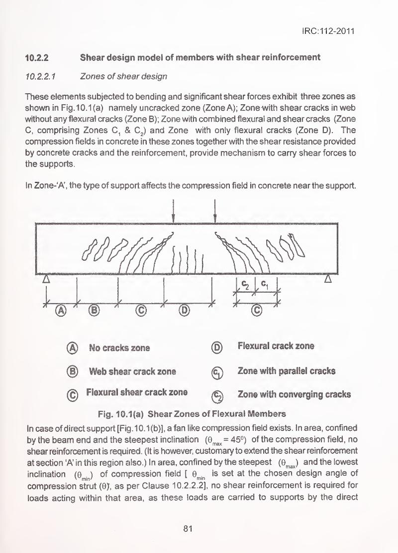
IRC:112-2011
10.2.2 Shear design model of members with shear reinforcement
10.2.2.1 Zones ofshear design
These elements subjected to bending and significant shear forces exhibit three zones as
shown in Fig. 10.1 (a) namely uncracked zone (Zone A); Zonewith shear cracks in webwithout any flexural cracks (Zone B); Zone with combined fiexural and shear cracks (Zone
C, comprising Zones & C^) and Zone with only flexural cracks (Zone D). The
compression fields in concrete in these zones together with the shear resistance provided
by concrete cracks and the reinforcement, provide mechanism to carry shear forces to
the supports.
In Zone-'A', the type of support affects the compression field in concrete near the support.
® No cracks zone -. @ Flexural crack zone
@ Web shear crack zone " @ Zone with parallel cracks
@ Flexural shear crack zone q Zone with converging cracks
Fig. 1 0.1 (a) Shear Zones of Flexural Members
in case of direct support [Fig. 10.1 (b)], a fan like compression field exists. In area, confined
by the beam end and the steepest inclination (e^^ = 45°) of the compression field, no
shear reinforcement is required. (It is however, customary to extend the shear reinforcement
at section 'A' in this region also.) In area, confined by the steepest {Q^J and the lowest
inclination (o^j of compression field [ 0^.^ is set at the chosen design angle of
compression strut (8>, as per Clause 10.2.2.2], no shear reinforcement is required for
loads acting within that area, as these loads are carried to supports by the direct
81
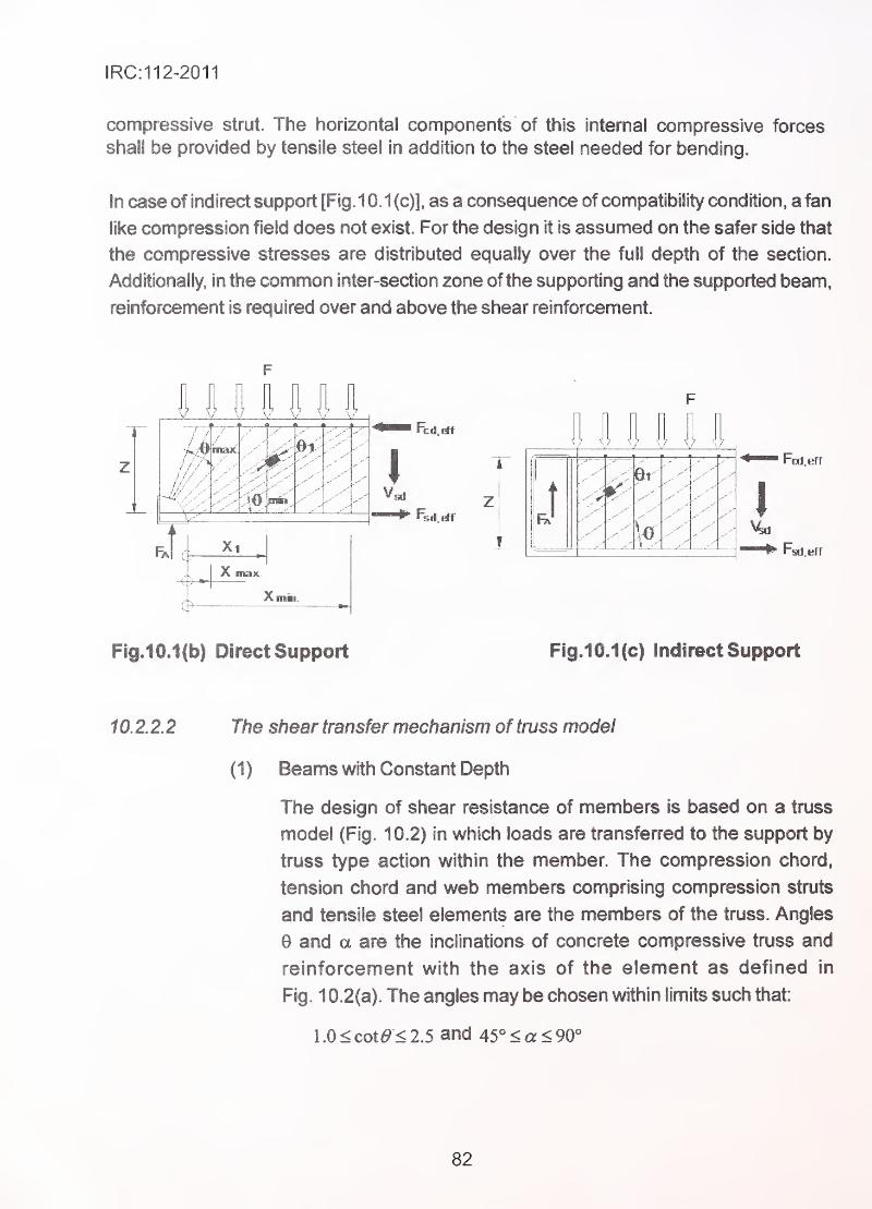
IRC:112-2011
compressive strut. The horizontal components of this interna! compressive forces
shall be provided by tensile steel in addition to the steel needed for bending.
In case of indirect support [Fig. 10.1 (c)l. as a consequence of compatibility condition, a fan
like compression field does not exist. For the design it is assumed on the safer side that
the compressive stresses are distributed equally over the full depth of the section.
Additionally, In the common inter-section zone of the supporting and the supported beam,
reinforcement is required over and above the shear reinforcement.
If/A
01
Xi
I
Fsd. t
et
'...S..} ^„..l ^.
Fcd.efr
I
Fsd eff
Fig.10.1(b) Direct Support Fig.1 0.1(c) Indirect Support
10.2.2.2 The shear transfer mechanism of truss model
(1) Beams with Constant Depth
The design of shear resistance of members is based on a truss
model (Fig. 10.2) in which loads are transferred to the support by
truss type action within the member. The compression chord,
tension chord and web members comprising compression struts
and tensile steel elements are the members of the truss. Angles
6 and a are the inclinations of concrete compressive truss and
reinforcement with the axis of the element as defined in
Fig. 1 0.2(a). The angles may be chosen within limits such that:
1.0<cot6>'<2.5 and 45°<a<90°
82
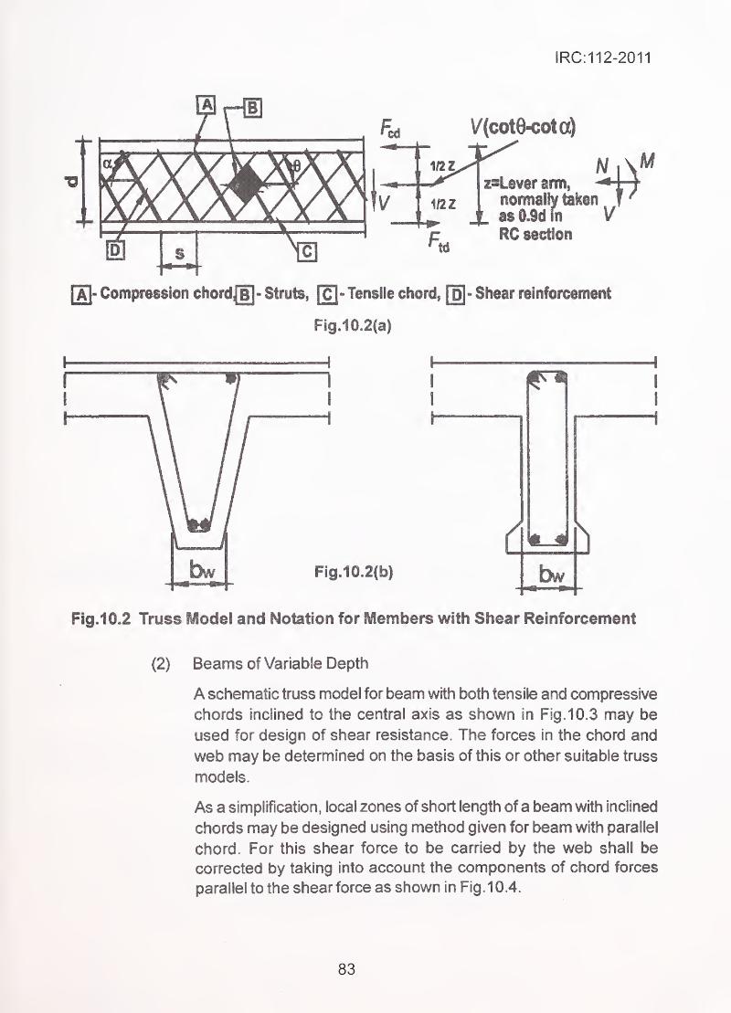
IRC:112-2011
V(C0te-C0tG^
srm,
normally taksn.
,
Jl as 0.9(1 in VRC section
[a|- Compression ohordje]- Struts, [c]- Tensile chord, [§- Shear reinforcement
FigJ0.2(a)
4
I
dFigJ©»2fb|
b
Fig.10.2 Truss Model and Notation for Members with Shear Reinforcement
(2) Beams of Variable Depth
A schematic truss model for beam with both tensile and compressive
chords inclined to the centra! axis as shown in Fig. 10.3 may be
used for design of shear resistance. The forces in the chord and
web may be determined on the basis of this or other suitable truss
models.
As a simplification, local zones of short length of a beam with inclined
chords may be designed using method given for beam with parallel
chord. For this shear force to be carried by the web shall be
corrected by taking into account the components of chord forces
parallel to the shear force as shown in Fig. 10.4.
83
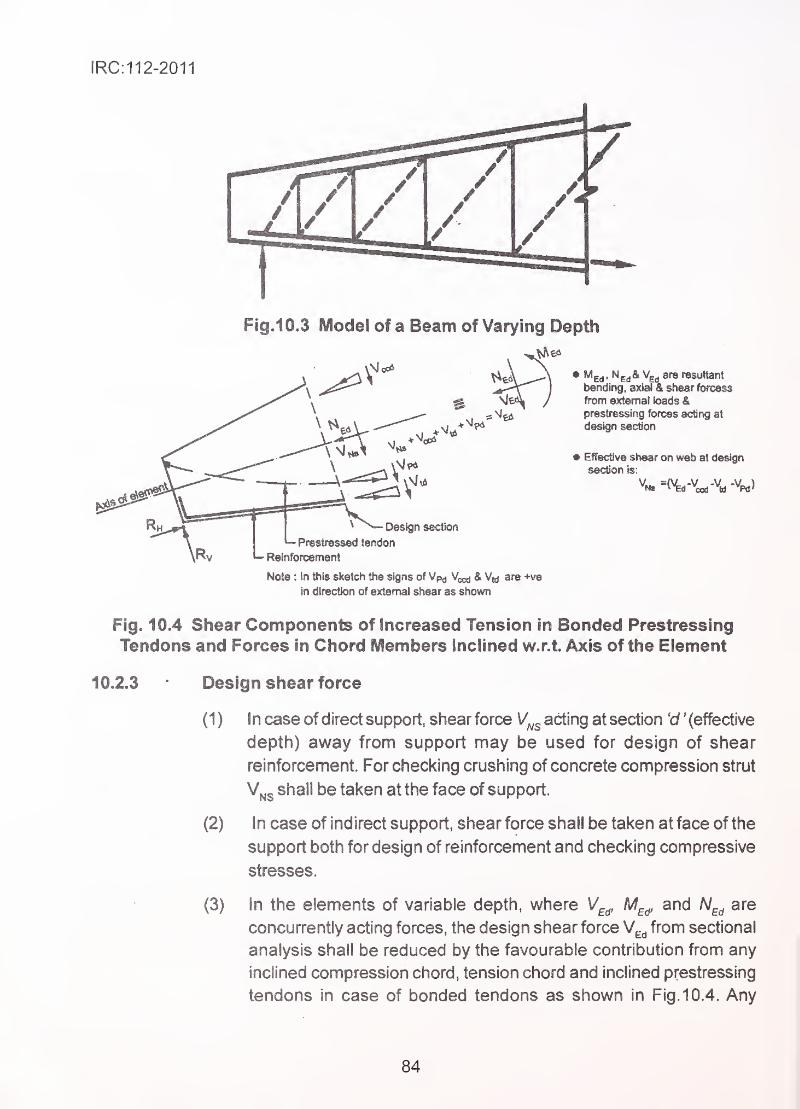
IRC:112-2011
Fig.10.3 Model of a Beam of Varying Depth
Woe*resultant
shesrforcsss
external loads &prestressing forces acting at
9 Effective shear on web at design
section is:
• Design section
^ Prestressed tendon
Relnforcefnent
Note : In this sketch the signs of Vp^ Vccd & are +ve
in direction of external shear as shown
Fig. 10.4 Shear Components of Increased Tension in Bonded Prestressing
Tendons and Forces in Chord Members Inclined w.r.t. Axis of the Element
10.2.3 Design shear force
( 1 ) In case of direct support, shear force V^^ acting at section 'd ' (effective
depth) away from support may be used for design of shear
reinforcement. For checking crushing of concrete compression strut
V^5 shall be taken at the face of support.
(2) In case of indirect support, shear force shall be taken at face of the
support both for design of reinforcement and checking compressive
stresses.
(3) In the elements of variable depth, where V^^, M^^ and N^^ are
concurrently acting forces, the design shear force V^^ from sectional
analysis shall be reduced by the favourable contribution from any
inclined compression chord, tension chord and inclined prestressing
tendons in case of bonded tendons as shown in Fig. 10.4. Any
84
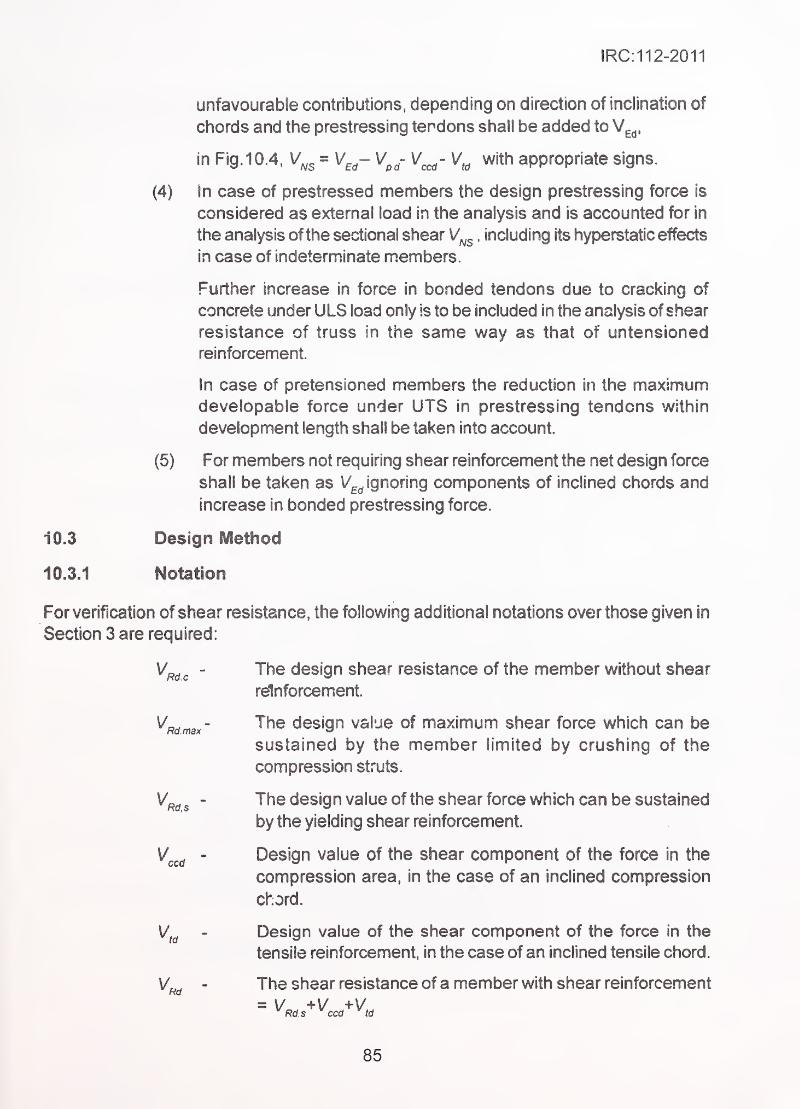
IRC:112-2011
unfavourable contributions, depending on direction of inclination of
chords and the prestressing tendons shall be added to V^^,
in Fig. 10.4, V^^ = V^^- V^^- V^- V^^ with appropriate signs.
(4) in case of prestressed members the design prestressing force is
considered as external load in the analysis and is accounted for in
the analysis ofthe sectional shear V^^ . including its hyperstatic effects
in case of indeterminate members.
Further increase in force in bonded tendons due to cracking of
concrete under ULS load only is to be included in the analysis ofshear
resistance of truss in the same way as that of untensioned
reinforcement.
In case of pretensioned members the reduction in the maximumdevelopable force under UTS in prestressing tendons within
development length shall be taken into account.
(5) For members not requiring shear reinforcement the net design force
shall be taken as \/^^ ignoring components of inclined chords and
increase in bonded prestressing force.
10.3 Design Method
10.3.1 Notation
For verification of shear resistance, the following additional notations over those given in
Section 3 are required:
The design shear resistance of the member without shear
rdnforcement.
The design value of maximum shear force which can be
sustained by the member limited by crushing of the
compression struts.
The design value of the shear force which can be sustained
by the yielding shear reinforcement.
Design value of the shear component of the force in the
compression area, in the case of an inclined compression
chord.
Design value of the shear component of the force in the
tensile reinforcement, in the case of an inclined tensile chord.
The shear resistance of a member with shear reinforcement
Rd s ccd td
Rd.c
V.Rd max
Rd.s
ccd
td
V.Rd
85
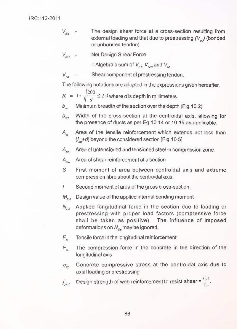
IRC:112-2011
- The design shear force at a cross-section resulting from
external loading and that due to prestressing fVy (bonded
or unbonded tendon)
- Net Design Shear Force
= Algebraic sum of V^^ and
^pd " Shear component of prestressing tendon.
The following notations are adopted in the expressions given hereafter.
K = 1 +J— ^ 2.0 where c/is depth in millimeters.
Minimum breadth of the section over the depth (Fig. 10.2)
b^^ Width of the cross-section at the centroidal axis, allowing for
the presence of ducts as per Eq.10.14 or 10.15 as applicable.
Area of the tensile reinforcement which extends not less than
(Z^+d) beyond the considered section [Fig.10.5]
A^^ Area of untensioned and tensioned steel in compression zone.
Area of shear reinforcement at a section
S First moment of area between centroidal axis and extreme
compression fibre about the centroidal axis.
/ Second moment of area of the gross cross-section.
M^^ Design value of the applied internal bending moment
H^^ Applied longitudinal force in the section due to loading or
prestressing with proper load factors (compressive force
shall be taken as positive). The influence of imposed
deformations on H^^ may be ignored.
Tensile force in the longitudinal reinforcement
The compression force in the concrete in the direction of the
longitudinal axis
cr.p Concrete compressive stress at the centroidal axis due to
axial loading or prestressing
f . Design strength of web reinforcement to resist shear =
86
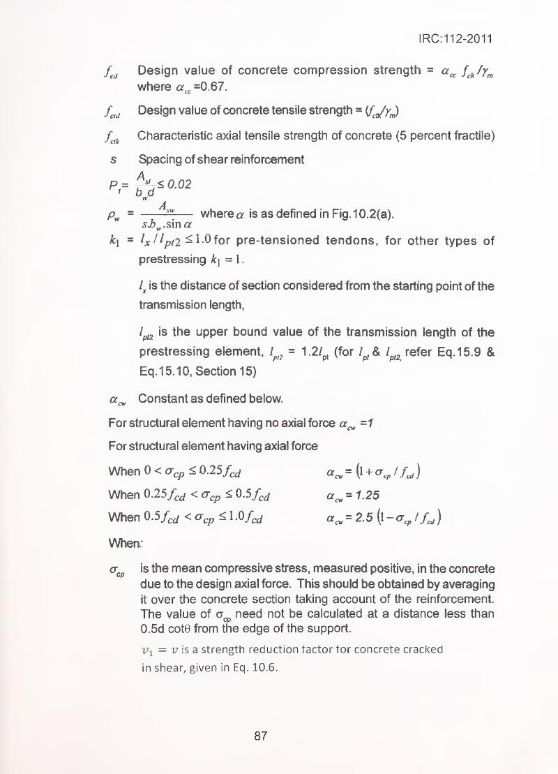
IRC: 11 2-2011
Design value of concrete compression strength = a^^ ScJVmwhere a^^ =0.67.
f^^^ Design value of concrete tensile strength = if^Jy^
f^^ Characteristic axial tensile strength of concrete (5 percent fractile)
s Spacing of shear reinforcement
A= i25L__ wherea is as defined in Fig. 10.2(a).
k\ = Ix^^ptl ^ 10 for pre-tensioned tendons, for other types of
prestressing k\=\.
is the distance of section considered from the starting point of the
transmission length,
the upper bound value of the transmission length of the
prestressing element, 1^,^= 1 (for /^^A l^^ refer Eq.15.9 &
Eq.15.10, Section 15)
Constant as defined below.
For structural element having no axial force a^=1
For structural element having axial force
When 0<a^p< 0.25/,.^ «^=(l + a^, I)
When 0.25/^j < < 0.5/^^ a^^1.25
When 0.5/^j<cTe^< 1.0/^^ a^ = 2.5\^~a,^l f,,)
When;
is the mean compressive stress, measured positive, in the concrete
due to the design axial force. This should be obtained by averaging
it over the concrete section taking account of the reinforcement.
The value of need not be calculated at a distance less than
0.5d cote from the edge of the support.
Vy = 17 is a strength reduction factor tor concrete cracked
in shear, given in Eq. 10.6.
87
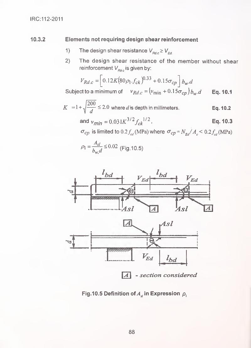
IRC:112-2011
10.3.2 Elements not requiring design shear reinforcement
1) The design shear resistance \/^^^> \/^^
2) The design shear resistance of the member without shear
reinforcement V^^^ is given by:
^Rd.c= 0A2K{mp^J,J-^^ +0.150-,cp
Subject to a minimum of vj^^ ^ =l^min + O.lScr^pj^^.^/ Eq. 10J
K =1 +1200
< 2.0 where fi? is depth in millimeters. Eq. 10.2
Eq. 10.3
Ocp is limited to 0.2 /^^ (MPa) where ^cp = ^e/'^c ^ 0.2/^^ (MPa)
p^=J^<0.02(pjgio.5)
.1 iUsl l3 lisl iZl
\A I- section considered
Fig.10.5 Definition of In Expression pj
88
IRC:112-2011
/l ^; is the tensile reinforcement which extends by length greater than
+ d beyond the section considered (Fig 10.5).
In prestressed single span members without design shear
reinforcement both Zone B and Zone C may exist. For Zone C,
cracked in bending, the expression for V^^^^ as given in Eq.10.1
can be used For Zone B uncracked in bending, where the flexural
tensile stress in the region under maximum bending moment is smaller
than X/* 05 ^Xm • the shear resistance should be limited by the tensile
strength of concrete. In these regions, the shear resistance is given
^'Rdc - ^^^idf ^^l^cpfcni' Eq. 10.4
Where notations are as per Section 10.3.1.
For cross-sections where the width varies over the height, the
maximum principal stress may occur on an axis other than the
centroidal axis. In such a case the minimum value of the shear
capacity should be found by calculating V^^^ at various axes in the
cross-section.
The calculation of the shear resistance according to the Eq.10.4 is
not required for cross-sections between the support and the section
which contains the intersection of the elastic centroidal axis and a
line inclined from the inner edge of the support at an angle of 45"
For members with loads applied on the upper side at a distance a^,
where is within 0.5d to 2d. from the edge of a support (or centre
of bearing where flexible bearings are used), the contribution of
this load to the shear force V^^ may be multiplied by /? = aJ 2 d.
This reduction may be applied for checking V^,, in Eq.10.1. This is
only valid provided that the longitudinal reinforcement is fully
anchored at the support For a^< 0 5d the value a^ = 0.5d should
be used. •
.
^
'
The shear force V^.^, calculated without reduction by /I should
however always satisfy the condition.
V^j<0.5b,,civf,j Eq.10.5
89
IRC: 11 2-2011
where visa strength reduction factor for concrete cracked in shear.
v = 0.6 X [1-fJ310], where fck is in Mpa Eq. 10.6
(6) For the design of longitudinal reinforcement in the region cracked
in flexure, the M^Jine shall be shifted over a distance ai =d in the
unfavourable direction (Ref. Section 16.5.1 3 and Fig. 16.2).
10.3.3 Members requiring design shear reinforcement
10.3.3.1 Shear resistance ' '
(1) The shear resistance of concrete flexural element in a truss model
is dependent on the longitudinal reinforcement provided in the
tension zone. For full effectiveness at the design section of shear,
the longitudinal reinforcement shall extend not less than
AI = «icot^+4i/ beyond the section considered where 'cf is the
effective depth and ^ the anchorage length (Fig. 10. 5). The area
of bonded prestressing steel may be included.
(2) Failure ascribable to web compression will be sudden andhence shall be avoided.
(3) The shear at the interface between concrete cast at different times
requires additional precautions as detailed in Clause 10.3.4.
(4) To find the least amount of shear reinforcement, for low andintermediate shear stresses, the lower limits of 0 given in
Clause 10.2.2.2 will normally govern the design. For higher shear
stresses, the value of 9 may be found by equating the design shear
force to V^^^^. The amount of shear reinforcement is then found
by equating the design shear force V^^ to U^^^ The value of 0 mayalternatively selected to optimize the design, forexample by minimizing
the total amount of reinforcement.
10. 3. 3.2 Members with vertical shear reinforcement
For members with vertical shear reinforcement, the shear resistance,
'. V^is the smaller value of:
^Rci.s=^^fywd^olO Eq. 10.7
and
where
A is the cross-sectional area of the shear reinforcement.Sw
90
IRC:112-2011
s is the spacing of the stirrups
f^^ is the design strength of web reinforcement to resist
shear =Ym.
= V is a strength reduction factor for concrete cracked in shear
given in Eq 10.6.
. z • lever arm can be taken as 0.9d for RCC section and to be
calculated for PSC section. .
•
is a coefficient taking account of the state of the stress in
the compression chord:
ctcw where 0
.
for 0<a-^<0.25^)
125;
for 0.254, <a^<0.5/J
2-5(t- for0.5f^<a^<10/J Eq.10.9
where
= is the mean compressive stress, measured positive, In the concrete
due to the design axial force. This shouk) be obtained by averaging
'
•
it over the concrete section taking account of the reinforcement.
The value of need not be calculated at a distance less than
0.5d cot 0 from the edge of the support.
Note: The maximum effective cross-sectional area of the shear reinforcement A^^^ for
cot 6=1 is given by:
-^-j—^-^cwnfcd Eq.10.10
10.3.3.3 Members with inclined shear reinforcement
(1 ) For members with inclined shear reinforcement the shear resistance
is the smaller value of
:
and
^Rd.msK - «cH'^w^l/ci/(cot^ + cot a)/ (l + cot^ d) Eq.10.12
Note: The maximum effective shear reinforcement, A^ior cot 9 = 1 follows from:
91
IRC:112-2011
sin a
(2) Bent up bars shall not be used as shear reinforcement except in
combination with vertical stirrups. At least 50 percent of V^^ shall
be resisted by vertical stirrups.
(3) For inclined shear reinforcement, the angle between the
reinforcement and the longitudinal axis of the beam (ci) should not
be less than 45°.
(4) In regions where there is no discontinuity of V^^ (e.g. for uniformly
distributed loading) the shear reinforcement in any length increment
/= z (cot 0+ cot (/) may be calculated using the smallest value of
V^^ in the increment.to
(5) Where the web contains grouted ducts with a diameter o<bJ8 the
shear resistance should be calculated on the basis of aHQ fY}Bx
nominal web thickness given by:
b =b -0.51(1) . Eq.10.14
where ^ is the outer diameter of the duct and I(f> '\s determined
for the most unfavourable level.
For grouted metal ducts with i^<b^/B, b^^^^ = b^
For non-grouted ducts, grouted plastic ducts and unbonded
tendons the nominal web thickness is:
f',^ = b,-1-2^^.
Eq.10.15
The value 1 .2 In Eq.10.15 is introduced to take
account of splitting of the concrete struts due to transverse
tension. If adequate transverse reinforcement is provided this
value may be reduced to 1.0.
(6) The additional tensile force, AF^^, in the longitudinal reinforcement
due to shear V^^ may be calculated from:
AF^^ = 0.5 V^^ (cot 0 - cot a) Eq.10.16
(M^/z}+A F^^ should be taken not greater than M^^^JZ, where
M^^ is the maximum moment along the beam.
I
92
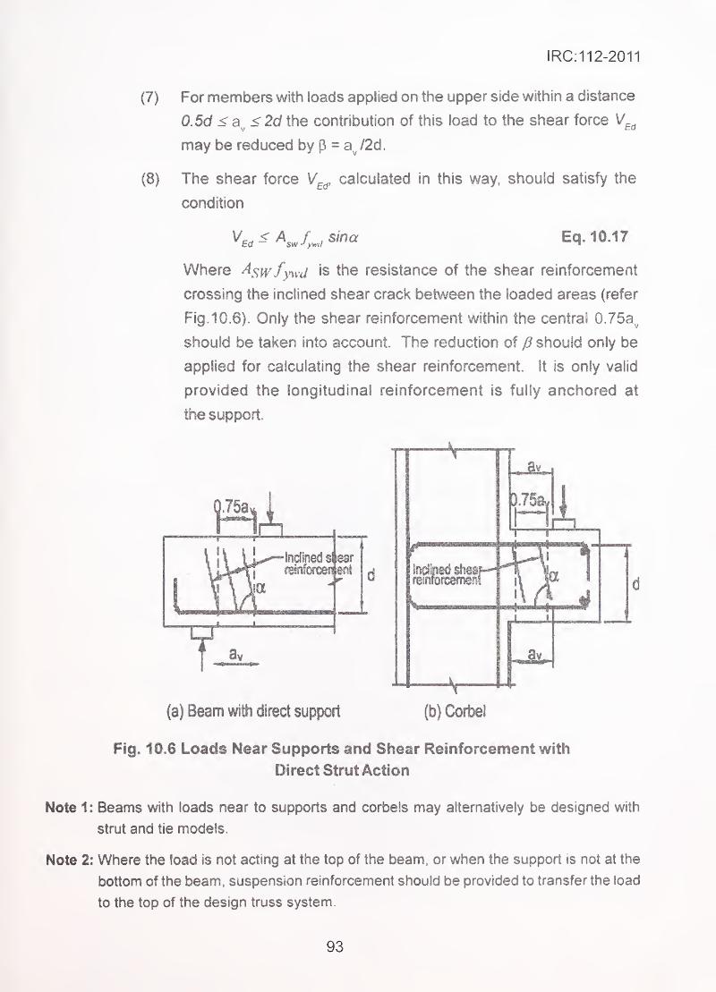
IRC:112-2011
(7)
(8)
For members with loads applied on the upper side within a distance
0.5d <a^<2d the contribution of this load to the shear force \/,
may be reduced by p = a /2d.
Ed
The shear force V^^, calculated in this way, should satisfy the
condition
Eq. 10.17
Where ^swfyM-d is the resistance of the shear reinforcement
crossing the inclined shear crack between the loaded areas (refer
Fig. 10.6). Only the shear reinforcement within the central 0.75a.,
should be taken into account. The reduction of should only be
applied for calculating the shear reinforcement, it is only valid
provided the longitudinal reinforcement is fully anchored at
the support.
(a) Beam with direct support (b) Corbel
Fig. 10.6 Loads Near Supports and Shear Reinforcement with
Direct Strut Action
Note 1: Beams with loads near to supports and corbels may alternatively be designed with
strut and tie models.
Note 2: Where the load is not acting at the top of the beam, or when the support is not at the
bottom of the beam, suspension reinforcement should be provided to transfer the load
to the top of the design truss system.
93
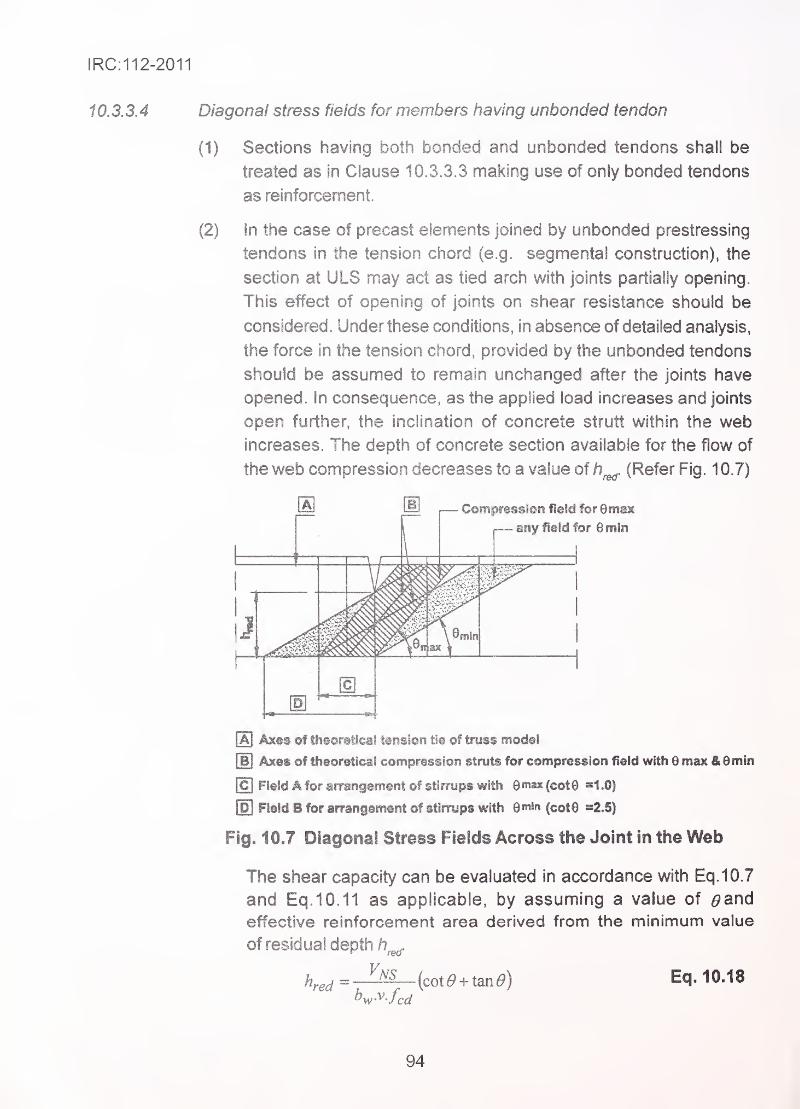
IRC:112-2011
10.3.3.4 Diagonal stress fields for members having unbonded tendon
(1) Sections having both bonded and unbonded tendons shall be
treated as in Clause 10.3.3.3 making use of only bonded tendons
as reinforcement.
(2) in the case of precast elements joined by unbonded prestressing
tendons in the tension chord (e.g. segmental construction), the
section at ULS may act as tied arch with joints partially opening.
This effect of opening of joints on shear resistance should be
considered. Under these conditions, in absence of detailed analysis,
the force in the tension chord, provided by the unbonded tendons
. should be assumed to remain unchanged after the joints have
opened. In consequence, as the applied load increases and joints
open further, the inclination of concrete strutt within the web
increases. The depth of concrete section available for the flow of
the web compression decreases to a value of h (Refer Fig. 1 0.7)
Ia] Axfts of theoretical tension tie of truss model
[b] Axes of theoretical compression struts for compression field with 6 max &8min
\C\ Field A for arrangement of stirrups with Qmm (cotG =1.0)
[H Field B for arrangement of stirrups with Qmin (cot9 =2.5)
Fig. 10.7 Diagonal Stress Fields Across the Joint in the Web
The shear capacity can be evaluated in accordance with Eq.10.7
and Eq.10.11 as applicable, by assuming a value of 0an6
effective reinforcement area derived from the minimum value
of residual depth
h^^^ ^_J^(cot^ + tan^) Eq. 10.18
94
IRC:112-2011
Shear reinforcement stirrups, having the following area (Eq. 10.19)
per unit length should be provided within a distance /i^^^ cot^ , but
not greater than the segment length, from both edges of the joint.
The prestressing force should be increased, if necessary, such that
at the ultimate limit state under the combination of bending momentand shear, the joint opening is limited to the value h-h^. The value
of hred shall be more than 0.5^.
10.3.3.5 Minimum shear reinforcement
For beams, minimum shear reinforcement ratio {p^J shall be
0072^/7k=
fyk
10.3.4 Interface shear
Eq. 10.20
The shear stress that arises between the interfaces of concrete placed at different times is
refenred to as interface shear.
Precast beam with cast-in-situ stiab is one of the typical case where interface shear has to
be designed for.
The interface shear is resisted by friction at the interface and by reinforcement placed
across the shear plane.
The interface shear stress should satisfy the following:
where,
V < V^ Edi — Rdi
^Edi is the interface shear stress
V is the resisting capacity at section.
V Edr P ^e/^^/
p is the ratio of the longitudinal force in the new concrete
and the total longitudinal force.
is the transverse shear force.
is the lever arm and^Edi
b. is the width of the interface.
95
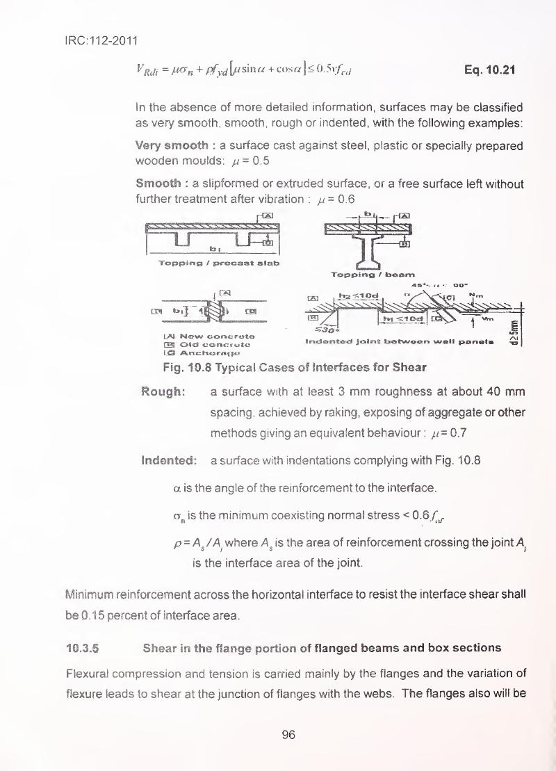
IRC:112-2011
VgJi^M^„ + ffydy^^na-i-c^ysf4<(^•y^:frJ,
Eq. 10.21
In the absence of more detailed information, surfaces may be classified
as very smooth, smooth, rough or indented, with the following examples:
Very smooth : a surface cast against steei, plastic or specially prepared
wooden moulds: /i = 0.5
Smooth : a slipformed or extruded surface, or a free surface left without
further treatment after vibration : // = 0.6
1J~~U=S' ^^^^^^Topping / precsast slab
t^l Ne»w cortcrotciOil OSd <;ortc:rc»t:«s
Fig. 10.8 Typical Cases of interfaces for Shear
Rough: a surface with at least 3 mm roughness at about 40 mm
spacing, achieved by raking, exposing of aggregate or other
methods giving an equivalent behaviour : //= 0.7
Indented: a surface with indentations complying with Fig. 1 0.8
a is the angle of the reinforcement to the interface.
is the minimum coexisting normal stress < 0.6 /'^
p^A^ /A where is the area of reinforcement crossing the joint A
is the interface area of the joint.
Minimum reinforcement across the horizontal interface to resist the interface shear shall
be 0.1 5 percent of interface area.
10.3.5 Shear in the flange portion of flanged beams and box sections
Flexural compression and tension is carried mainly by the flanges and the variation of
flexure leads to shear at the junction of flanges with the webs. The flanges also will be
96
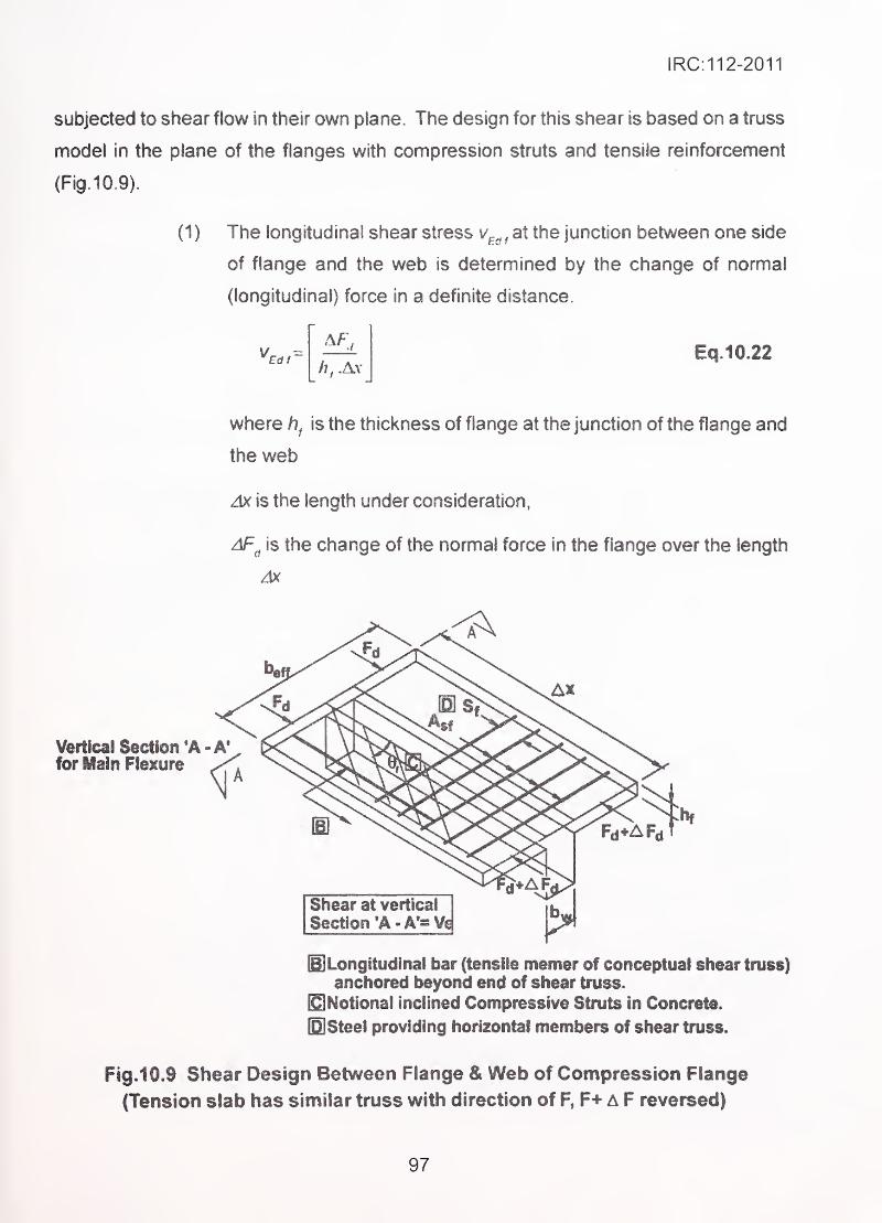
IRC:112-2011
subjected to shear flow in their own plane. The design for this shear is based on a truss
model in the plane of the flanges with compression struts and tensile reinforcement
(Fig.10.9).
(1) The longitudinal shear stress v^, , at the junction between one side
of flange and the web is determined by the change of normal
.
.(longitudinal) force in a definite distance.
h, AyEq.10.22
where is the thickness of flange at the junction of the flange and
the web
Ak is the length under consideration,
AF^ is the change of the normal force in the flange over the length
Vertical Section 'A -A'for Main Flexure
Shear at vertical
Section *A- A*- Vci
mLongitudinal bar (tensile memer of conceptual shear truss)
anchored beyond end of shear truss.
Notional inclined Compressive Struts in Concrete.
IQ]Steel providing horizontal members of shear truss.
Fig.10.9 Shear Design Between Flange & Web of Compression Flange
(Tension slab has similar truss with direction of F, F+ A F reversed)
97
IRC:112-2011
(2) The transverse reinforcement per unit length
determined as follows:
may be
Eq. 10.23
For verification of concrete compression /7^shouid be reduced by
the depth of concrete compression zone in transverse bending.
To prevent crushing of the compression struts in the flange, the
following condition should be satisfied
^ vfcd sin 9f cos 6f
Note: The recommended values in the absence of more rigorous calculation
are: . ,
1.0< cot Of <2,0 for compression flanges (46* >e,> 26,51
1.0< cot 0f< 1,25 for tension flanges (45° > 9^ > 38,6")
(3) in the case of combined shear between the flange and the web,
and transverse bending, the area of steel should be the greater of
that given by Eq.10.23 or half that given in Eq. 10.23 plus that
required for transverse bending.
(4) If V^^ is less than or equal to 0.4^^^ no extra reinforcement above
that for flexure is required.
(5) Longitudinal tension reinforcement in the flange should be anchored
beyond the strut required to transmit the force back to the web at
the section where this reinforcement is required (Refer Fig. 10. 9).
The rules in this Section are complementary to those given in earlier Sections. This Section
covers shear due to punching force (penetrating force) on two dimensional structural
elements such as deck slabs, soffit slab, well caps and open foundations. The word 'slab'
represents all these in Clausel 0.4.
The punching nomnally happens when a concentrated force (load or reaction) acts over a
small area of the two dimensional structural element and causes local shear failure
surrounding the concentrated force in the element.
10,4 Design for Punching Shear
10.4.1 General
98
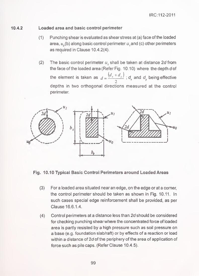
iRC:112-2011
10.4.2 Loaded area and basic control perimeter
(1 ) Punching shear is evaluated as shear stress at (a) face of the loaded
area, u^ib) along basic control perimeter u,and (c) other perimeters
as required in Clause 10.4.2(4).
(2) The basic control perimeter shall be taken at distance 2d from
the face of the loaded area (Refer Fig. 10.10) where the depth dof
the element is taken as = ^> ^; d and d being effective
depths in two orthogonal directions measured at the control
perimeter.
Fig. 10.10 Typical Basic Control Perimeters around Loaded Areas
(3) For a loaded area situated near an edge, on the edge or at a comer,
the control perimeter should be taken as shown in Fig. 10.11. In
such cases special edge reinforcement shall be provided, as per
Clause 16.6.1.4.
(4) Control perimeters at a distance less than 2d should be considered
for checking punching shear where the concentrated force of loaded
area is partly resisted by a high pressure such as soil pressure on
a base (e.g. foundation slab/raft) or by effects of a reaction or load
within a distance of 2d of the periphery of the area of application of
force such as pile caps. (Refer Clause 1 0.4.5).
99
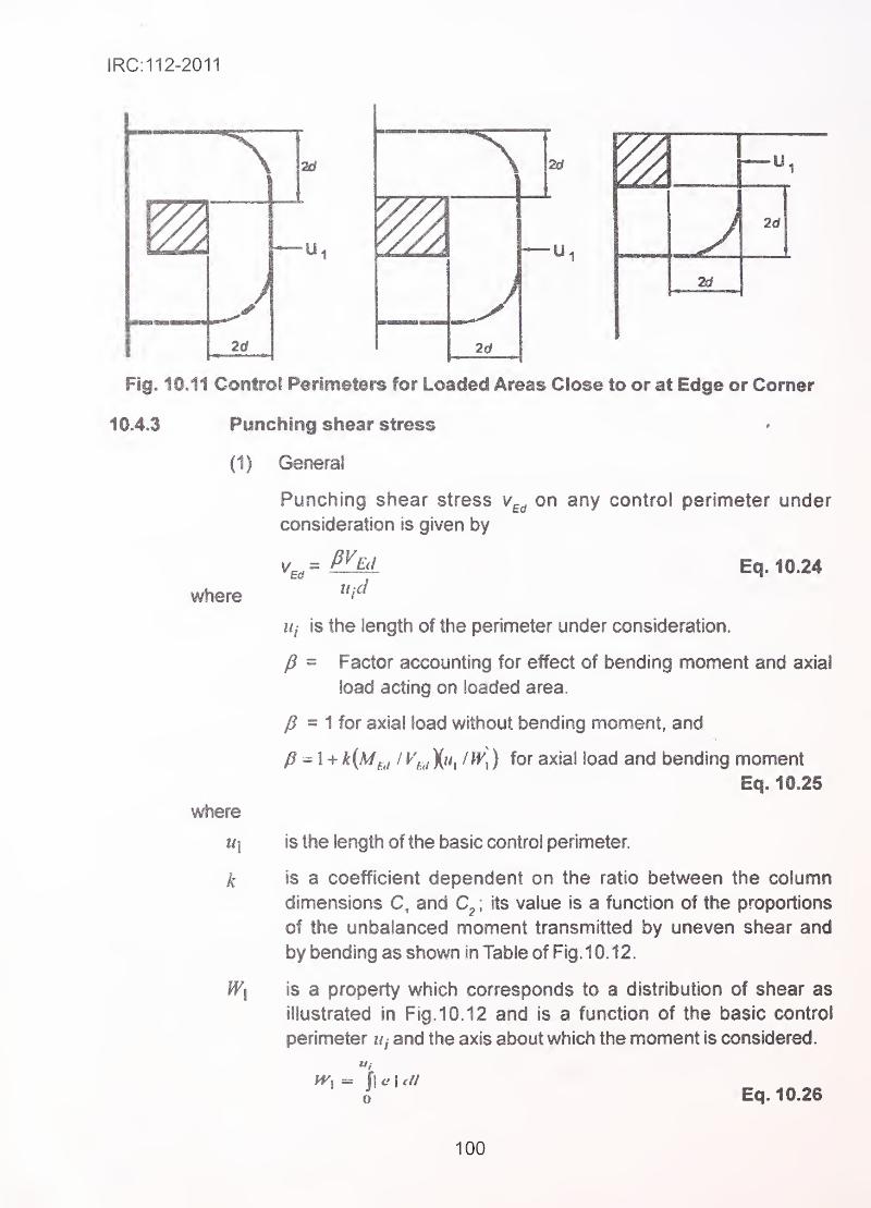
IRC:112-2011
2d
m u
2d
— "1
2d
Fig. 10.11 Control Perimeters for Loaded Areas Ciose to or at Edge or Corner
10.4.3 Punching shear stress »
(1) General
Punching shear stress on any control perimeter under
consideration is given by
where
where
k
Uj is the length of the perimeter under consideration.
Eq. 10.24
fl= Factor accounting for effect of bending moment and axial
load acting on loaded area.
- Mor axial toad without bending moment, and
^ - 1 + k(Mfj I X"i / ^^^1 ) for axial load and bending momentEq. 10.25
is the length of the basic control perimeter.
is a coefficient dependent on the ratio between the column
dimensions C, and ; its value is a function of the proportions
of the unbalanced moment transmitted by uneven shear and
by bending as shown in Table of Fig. 10. 12.
is a property which corresponds to a distribution of shear as
illustrated in Fig. 10. 12 and is a function of the basic control
perimeter Uj and the axis about which the moment is considered.
'
, = \\e\ ell
„ Eq. 10.26
100
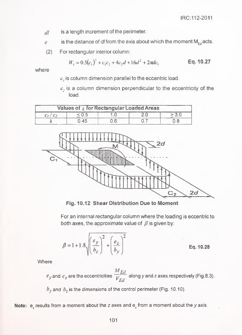
IRC:112-2011
(U
e
(2)
where
is a length increment of the perimeter.
is the distance of d/from the axis about which the moment M^^acts.
For rectangular interior column:
W, = 0.5(c',)' + c,L\_ + 4vJ + + Indc, ' Eq. 10.27
C/ is column dimension parallel to the eccentric load.
t\ is a column dimension perpendicular to the eccentricity of the
load.
Values of k for Rectangular Loaded Areas<0.5 1.0 2.0 >3.0
k 0.45 0.6 0.7 0.8
Fig. 10.12 Shear Distribotion Due to Moment
For an internal rectangular column where the loading is eccentric to
both axes, the approximate value of /J is given by:
i
J,
2 { \
+ Eq, 10.28
Where
MEde,,and are the eccentricities along y and z axes respectively {Fig. 8. 3).
^jand is the dimensions of the control perimeter (Fig. 10.10).
Note: e^. results from a moment about the z axes and from a moment about the y axis.
101
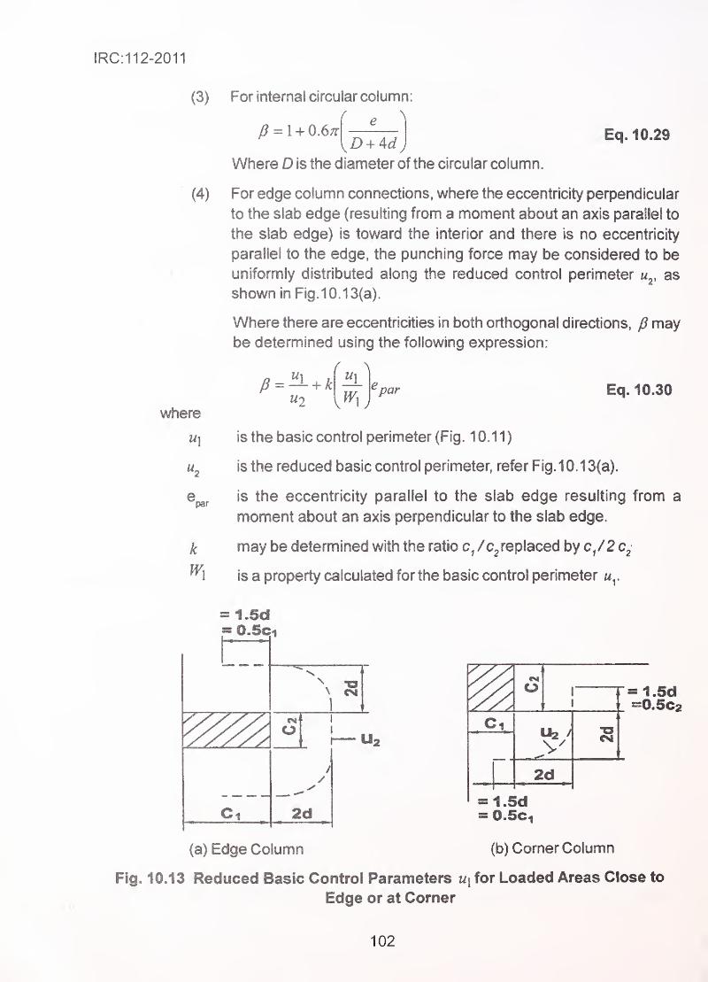
IRC:112-2011
(3)
(4)
where
Ml
par
k
For internal circular column
f P ^
/? = 1 + 0.6;t
Where D is the diameter of the circular column.J
Eq. 10.29
For edge column connections, where the eccentricity perpendicular
to the slab edge (resulting from a moment about an axis parallel to
the slab edge) is toward the interior and there is no eccentricity
parallel to the edge, the punching force may be considered to be
uniformly distributed along the reduced control perimeter m^, as
shown in Fig. 10.13(a).
Where there are eccentricities In both orthogonal directions, p maybe determined using the following expression:
«2par Eq. 10.30
is the basic control perimeter (Fig. 10.11)
is the reduced basic control perimeter, refer Fig. 10. 13(a).
is the eccentricity parallel to the slab edge resulting from a
moment about an axis perpendicular to the slab edge.
may be determined with the ratio /c^ replaced by c/2
is a property calculated for the basic control perimeter
= I.Sd= O.Sci
11
U2
2d
(a) Edge Column
2d
= 1.5db0.5C2
1.5d0.5Ci
(b) Corner Column
Fig. 10.13 Reduced Basic Control Parameters ux for Loaded Areas Close to
Edge or at Corner
102
IRC:112-2011
For a rectangular column as shown in Fig.1 0.1 3(a)
Wi=-^ + C]C2 + 4cid + Sd^ + ndc2 Eq. 10.314
If the eccentricity perpendicular to the slab edge is not toward the
interior, Eq. 10.25 applies. When calculating ffjthe eccentricity e
should be measured from the centroid of the control perimeter.
(5) For comer column, where the eccentricity is toward the interior of
the slab, it is assumed that the punching force is uniformly distributed
along the reduced control perimeter u^, as defined in Fig.1 0. 1 3(b).
The p -value may then be considered as:
P^~ir Eq. 10.322"
If the eccentricity is toward the exterior, Eq. 10.25 applies.
The value of will change depending upon the axis about which the
bending moment acts.
10.4.4 Punching shear resistance of slabs without shear reinforcement
The design punching shear resistance shall be assessed at the basic control
perimeter, according to Ciause 10.4.2. The design punching shear resistance (MPa) of
slab may be calculated as follows:
0 18v/?^/.c=— + (0.1cr,J> v^i„ +0.10-,^ Eq. 10.33
where ^
^ . •
.
fcj^ is in MPa
K =1 +J— < 2.0 where dis depth in millimeters. Eq. 10.34
Pi = -^PlyPlz ^ 0-02 Eq. 10.35
PlyPlz relate to the bonded tension steel in j-and z - directions
respectively. The values Piy and pi^ should be calculated as meanvalues taking into account a slab width equal to the column width
plus 3 each side.
(^cp=^^ Eq. 10.36
where
cTcy » ^cz are the axial concrete stresses in the critical section and directions
in MPa, (positive if compression):
^c,y =—— and ^c,z =—r^ Eq. 10.37^cy ^cz
103
IRC:112-2011
^Edy t ^f^/r^re the longitudinal forces. The force may be from a load or
prestressing action.
A^y . are the area of concrete resisting axial forces.
v,„i„=0.031if3/2/rf"2
10.4.6 Punching shear for foundation slabs and pile caps
(1 ) The punching resistance of column bases for open foundations and
piie caps should be verified at the face of the column and at control
perimeters within 2 d from the periphery of the column.
(2) For concentric loading the net applied force is
yEdred =^Ed-~^ ^Ed ,
Eq. 1 0.38
where
V£^l is the applied shear force
^^Ed net upward force within the control perimeter considered, i.e.
upward pressure from soil minus self-weight of base.
^Ed,red »- «**V... ,= ;— Eq. 10.39Ld.red ^ ^
=0A2K{mpJ,ky^^>v^;^^ Eq. 10.40a a
where
v^^ is punching shear resistance at control perimeter at distance a
a is the distance from the periphery of the column to the control
perimeter considered
.
J200—
- < 2.0 J in mm as defined in Eq. 1 0.34.
v„;„=0.03U^'-/a'" Eq. 10.41
(3) For eccentric loading
V
ud1 + i
V w Eq. 10.42
Where k is defined in Eq. 10.25 or Eq. 10.30 as appropriate and Wis similar to W, but for
perimeter u .
104
IRC:112-2011
Design of section for punching siiear
(1) In bridges, punching should be avoided by providing adequate
concrete thickness with sufficient reinforcement for resisting bending
and shear, which should also be capable of resisting the worst local
punching shear stresses.
(2) The design procedure for punching shear is based on checks at the
face ofthe column and at the basic control perimeter U] . The following
design shear stresses (MPa) along the control sections, are defined:
^Rd.c the design value of the punching shear resistance of a slab without
punching shear reinforcement along the control section considered.
VRd max '® the design value of the maximum punching shear resistance along
the control section considered.
where^
.
VRd.max=2''''fi'^ Eq.10.43
Where v is given in Eq. 10.6.
(3) The following checks should be carried out:
(a) At the column perimeter, or the perimeter of the loaded area, the
maximum punching shear stress should not be exceeded:
Where v£^ is given by Eq. 10.24 with »/ =
Where u :
o
- for an inner column = length of column, periphery in mm.- for edge column = C2+3d ^ C2+2C^(mm)- for corner column = 3d ^ C^+C2(mm)
(b) Punching shear reinforcement is not necessary if at control section.
^Ed<^Rdjc Eq.10.45
Torsion
General
(1) Torsional resistance in concrete elements, in which its longitudinal
fibres are free to deform in longitudinal direction, is categorized into
equilibrium torsion and compatibility torsion. Where the longitudinal
105
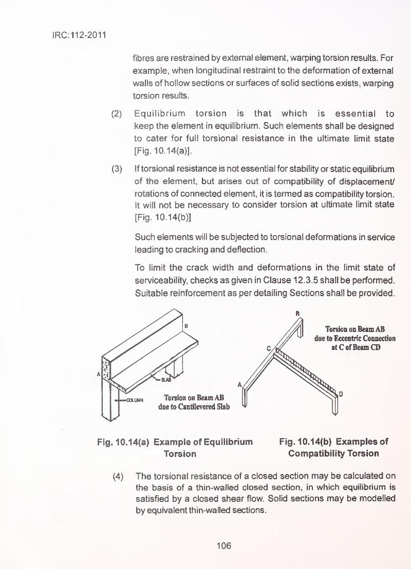
IRC:112-2011
fibres are restrained by external element, warping torsion results. For
example, when longitudinal restraint to the deformation of external
walls of hollow sections or surfaces of solid sections exists, warping
torsion results.
(2) Equilibrium torsion is that which is essential to
keep the element in equilibrium. Such elements shall be designed
to cater for full torsional resistance in the ultimate limit state
[Fig. 10.14(a)].
(3) If torsional resistance is not essential for stability or static equilibrium
of the element, but arises out of compatibility of displacement/
rotations of connected element, it is termed as compatibility torsion.
It will not be necessary to consider torsion at ultimate limit state
[Fig. 10.14(b)]
Such elements will be subjected to torsional deformations in service
leading to cracking and deflection.
To limit the crack width and deformations in the limit state of
serviceability, checks as given in Clause 12.3.5 shall be performed.
Suitable reinforcement as per detailing Sections shall be provided.
Fig. 10.14(a) Example of Equilibrium Fig. 10.14(b) Examples of
Torsion Compatibility Torsion
(4) The torsional resistance of a closed section may be calculated on
the basis of a thin-walled closed section, in which equilibrium is
satisfied by a closed shear flow. Solid sections may be modelled
by equivalent thin-walled sections.
106
IRC:112-2011
Complex shapes, such as T-sections, may be divided into a series
of sub-sections, each of which is modelled as equivalent thin walled
hollow section. The total torsional resistance is taken as sum of the
individual sub-sections.
(5) The distribution of the acting torsional moments over the sub-
sections should be in proportion to their uncracked torsional
stiffnesses. For hollow sections such as box sections, the equivalent
wall thickness should not exceed the actual wall thickness.
(6) Each sub-section may be designed separately. For conversion of
solid sub-section to equivalent hollow section procedure given in
Fig. 10. 16 defining the effective thickness of wall t^j-j may be
followed.
(7) In the analysis, torsional stiffness may be calculated on the following
basis:
(a) In case of equilibrium torsion, the stiffness should be based on
uncracked sectional resistance, i.e. gross-section.
(b) In case of compatibility torsion, the torsional stiffness may be
calculated on the basis of cracked section.
Torsional stiffness of cracked section may be assumed as
25 percent of that of the uncracked section (Refer Clause 7.4).
Design procedures
Hollow section and equivalent closed thin wall section
(1) The shear stress in a wall of a section subject to a pure torsional
moment may be calculated from:
^t>i - JJTTT Eq. 10.46
The design torsional shear force V^^ . in a wall T due to torsion is
given by V^j,= T,j^f ,z, where T^^ is the applied design torsion (see
Fig. 10.15).
(2) For resisting torsion, reinforcement has to be provided both in
longitudinal and transverse direction.
107
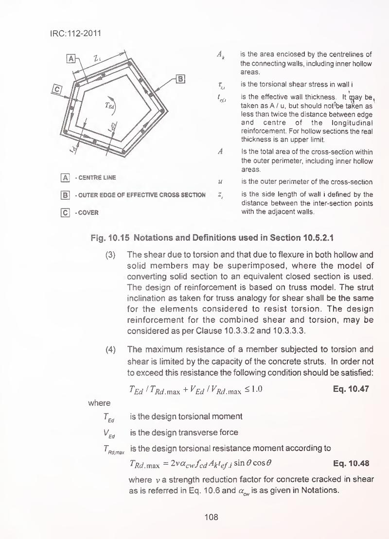
IRC:112-2011
AJ "CENTRELINE
B\ - OUTER EDGE OP EFFECTIVE CROSS SECTION
Cl -COVER
u
is the area enclosed by the centrelines of
the connecting walls, including inner hollow
areas.
is the torsional shear stress in wall i
is the effective wall thickness. It may be,
taken asA / u, but should not"be taken as
less than twice the distance between edgeand centre of the longitudinal
reinforcement. For hollow sections the real
thickness is an upper limit.
Is the total area of the cross-section within
the outer perimeter, including inner hollow
areas.
is the outer penmeter of the cross-section
is the side length of wall i defined by the
distance between the inter-section points
with the adjacent walls.
Fig. 10.15 Notations and Definitions used in Section 10.5.2.1
(3)
(4)
where
Ed
V,
The shear due to torsion and that due to flexure in both hollow and
solid members may be superimposed, where the model of
converting solid section to an equivalent closed section is used.
The design of reinforcement is based on truss model. The strut
inclination as taken for truss analogy for shear shall be the samefor the elements considered to resist torsion. The design
reinforcement for the combined shear and torsion, may be
considered as per Clause 10.3.3.2 and 10.3.3.3.
The maximum resistance of a member subjected to torsion and
shear is limited by the capacity of the concrete struts. In order not
to exceed this resistance the following condition should be satisfied:
'^Ed I '^Rd.m&x + ^Ed ' ^Rd. max ^ 1 Eq. 10.47
Ed
Rd.max
is the design torsional moment
is the design transverse force
is the design torsional resistance moment according to
TRd.max = '^^^cwfcd^khf.i sin 6? cos (9 Eq. 10.48
where v a strength reduction factor for concrete cracked in shear
as is referred in Eq. 10.6 and a is as given in Notations.
108
IRC:112-2011
^Rdmax maximum design shear resistance according to
Clause 10.3.3.2 and 10.3.3.3. in solid cross-sections the full
width of the web may be used to determine V^^^^^.
(5) The required cross-sectional area of the longitudinal reinforcement
for resisting torsion may be calculated from the equation
mentioned below:
where
col 6 Eq. 10.49
is the perimeter of the area /A^
is the design yield stress of the longitudinal reinforcement
6 is the angle of compression struts
In compressive chords, the longitudinal reinforcement may be reduced
in proportion to the available compressive force, in tensile chords
the longitudinal reinforcement for torsion should be added to the other
reinforcement. The longitudinal reinforcement should generally be
distributed over the length, z^(Fig.10.16).
Warping torsion
(1 ) For closed thin-walled sections and solid sections, warping torsion
may normally be ignored unless the longitudinal elongation of the
walls/surfaces of the section is restrained by other members.
(2) In open thin walled members it is necessary to consider warping
torsion. For very slender cross-sections the calculation should be
carried out on the basis of a beam grid model and for other cases
on the basis of a truss model, in all cases the design should be
canied out according to the design rules for bending and longitudinal
normal force, and for shear.
109

IRC:112-2011
SECTION 11 ULTIIiATE Lliy!!T STATE OF INDUCED DEFORMATION
11J General '
.
'
'
'''' ",
(1) This Section deals with structures and structural memberswhose load deformation behaviour and ultimate capacity
are significantly affected by second order effects. Second order effects
are defined as the additional effects of actions caused by structural
defomiations. Second order effects can be global, involving structure
as a whole, and/or local, involving some of its members, such as
columns, walls, compression flanges of beams etc.
(2) Classical buckling defined as sudden failure due to instability of
perfectly axially loaded members without horizontal load does not
usually occur in practical reinforced/prestressed concrete members.
However, long slender members at ultimate load exhibit large and
disproportionate increase of deflections due to combined effect of
geometric non-linearity (P-A effect) and non-linear structural
response due to material non-linearity, progressive cracking and
local plasticity. This reduces the ultimate load carrying capacity as
compared to the short members of identical cross-section and steel
ratio.
Therefore, long members should be designed to have higher
moment resisting capacity as compared to short members of
identical sectional details.
(3) Second order linear elastic method of analysis shall be used for
calculating second order effects. Equilibrium and resistance shall
be verified in the deformed state for the most unfavourable
combination of actions at ultimate limit state, taking into account
uncertainties in geometry and position of axial loads as additional
first order effects.
(4) The distinction between treatment of long column and short column
for purpose of this Section 1 1 is based on 10 percent criteria given
in (5) below.
Structural behaviour shall be considered in all directions in which
significant second order effects can occur. Biaxial bending shall
be taken into account when necessary.
(5) Second order effects may be ignored ifthey are less than 10 percent
of the corresponding first order effects, calculated on the basis of
(3) above.
110
IRC:112-2011
(6) In place of method described in (4) & (5) above, simplified criteria for
identifying short and long members are given for isolated membersof uniform cross-section in Clause 11 .2.
(7) For piers with variable sections and those acting as long composite
-
' system together with piles which are not laterally supported below
pile caps, (as in case of piles in river portion between the pile cap
and scour depth), full height of the substructure shall be analysed
using method described in (3). For piles fully embedded in
soil, the piers alone can be separately analysed for slenderness
. effects.
Simplified Slenderness Criteria
Slenderness criteria for isolated members fcolumns) of uniform
cross-section
(1) Slenderness Ratio
The slenderness ratio A is defined as l^/i, where / is the radius of
gyration of the uncracked concrete section. The effective length
is the length of a pin-ended column with constant axial force having
the same cross-section and same buckling load as the actual
member.
. (2) Second order effects may be ignored if the slenderness ratio A
based on as per Clause 1 1 .2.2 is less than a certain value A,^ as
per Eq.11.1.
A/,-^ =20.ABr/V« Eq.11.1
where
A - l/(l + 0.24y)
(i>g^is effective creep ratio.
MoEqp - First orderBM. in quasi-permanent load combination
in SLS.
^oEd ^ ^^^^^ order B.M. in design load combination in U.LS.
B = ^1 + 2(0
C = 1.7-1
111
IRC:112-2011
11.2.2
G} - Asfyd f(Acfcj) mechanical reinforcement ratio.
Ag = is the total area of longitudinal reinforcement.
n = Ngj l{Acfcd) relative normal force
m= Mq, /Mo2 moment ratio
Mq^M02 sre the first order end moments at two ends of member as
calculated from the analysis of structure, where |A/o,| > |Mo,|
.
If the end moments Mq, & give tension on the same side, should betaken positive (i. e. C < 1.7), otherwise negative (i. e. C>1.7).
In the following cases, should be taken as 1.0 (i.e. C = 0. 7):
For unbraced members in general.
For braced members in which the first order moments arise
predominantly from imperfections or transverse loading.
Note: For initial dimensioning of member, simplified values ofA =0.7, B =1.1,
C =0.7 may be used.
(3) In case of biaxial bending, the slenderness criterion may be checked
separately for each direction. Depending on the outcome of this
check, second order effects (a) may be ignored in both directions,
(b) should be taken into account in one direction, or (c) should be
taken into account in both directions.
Effective length (height) and slenderness ratio of columns and piers
with bearings
(1) For compression members in regular frames, the effective length
is determined in the following way:
Braced Members:
/. = 0.5/0.45
+
1 +0.45 + A:J
Eq.11.2
Unbraced members:
/, = 4 X maxofiV
^ ^ k1+ '
V1 +
1 +k.
2 /Eq.11.3
112
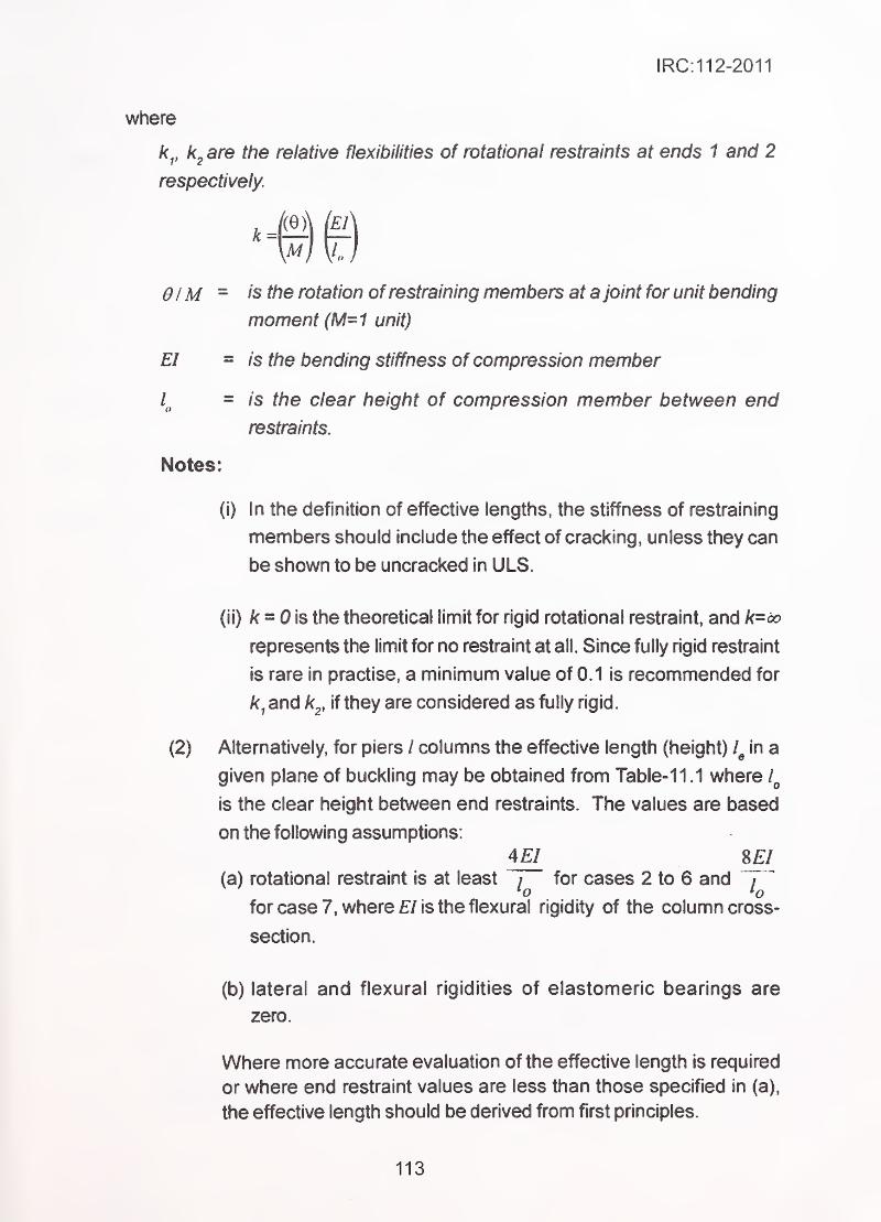
IRC:112-2011
where
k^, are the relative flexibilities of rotational restraints at ends 1 and 2
respectively.
01M - is the rotation of restraining members at a joint for unit bending
moment (M=1 unit)
EI = is the bending stiffness of compression member
= is the clear height of compression member between end
restraints.
Notes:
(i) In the definition of effective lengths, the stiffness of restraining
members should include the effect of cracking, unless they can
be shown to be uncracked in ULS.
(ii) k = 0 \s the theoretical limit for rigid rotational restraint, and k-oo
represents the limit for no restraint at all. Since fully rigid restraint
is rare in practise, a minimum value of 0.1 is recommended for
^,and k^, if they are considered as fully rigid.
(2) Alternatively, for piers / columns the effective length (height) in a
given plane of buckling may be obtained from Table- 11.1 where
is the clear height between end restraints. The values are based
on the following assumptions:
4EI SEI(a) rotational restraint is at least / for cases 2 to 6 and i
*o *ofor case 7, where EI is the flexural rigidity of the column cross-
section.
(b) lateral and flexural rigidities of elastomeric bearings are
zero.
Where more accurate evaluation of the effective length is required
or where end restraint values are less than those specified in (a),
the effective length should be derived from first principles.
113
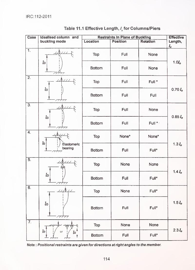
IRC:112-2011
Table 11.1 Effective Length, / for Columns/Piers
Case IdeaHsed column andbuckling mode Location
Restraints in Plane of BucklingPosition Rotation
Effective
Length,
le
1.
Top Full
Bottom Full
/ / 7'/ r
None
None
1.0/«
//\//
/
Top Full
Bottom Full
-/"////
Full
0.70 /o
Top Full
Bottom
h
31" Top None*
// / /
/
Elastomeric
bearingBottom Full
None
0.854
1.3 /«
5.
Top None
Bottom Full
Top None
Bottom Full
/ / / / /
h
Top None
or I
Bottom Full
None
Fuir
Full*
1.4 L
1.54
Full*
None
2.34
Full"
Note : Positional restraints are given for directions at rigtit angles to the member.
114
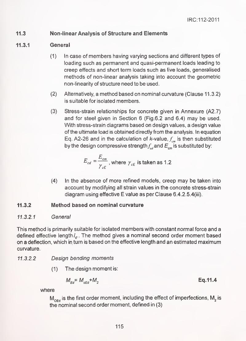
IRC:112-2011
11.3 Non-linear Analysis of Structure and Elements
11.3.1 General
(1) In case of members having varying sections and different types of
loading such as permanent and quasi-permanent loads leading to
creep effects and short term loads such as live loads, generalised
methods of non-linear analysis taking into account the geometric
non-linearity of structure need to be used.
(2) Alternatively, a method based on nominal curvature (Clause 1 1 .3.2)
is suitable for isolated members.
(3) Stress-strain relationships for concrete given in Annexure (A2.7)
and for steel given in Section 6 (Fig.6.2 and 6.4) may be used.
With stress-strain diagrams based on design values, a design value
of the ultimate load is obtained directly from the analysis. In equation
Eq. A2-26 and in the calculation of /(-value, / is then substituted~ ' •'cm
by the design compressive strengthy^^and E^^ is substituted by:
F^cd -
, where y^i^is taken as 1 .2
(4) In the absence of more refined models, creep may be taken into
account by modifying all strain values in the concrete stress-strain
diagram using effective E value as per Clause 6.4.2. 5.4(iii).
11.3.2 Method based on nominal curvature
11.3.2.1 General
This method is primarily suitable for isolated members with constant normal force and a
defined effective length/^. The method gives a nominal second order moment based
on a deflection, which in turn is based on the effective length and an estimated maximumcurvature.
11.3.2.2 Design bending moments
(1) The design moment is:
M,,= M^,,^M, Eq.11.4
where
'^oEd^"^^^ order moment, including the effect of imperfections, is
the nominal second order moment, defined in (3)
115
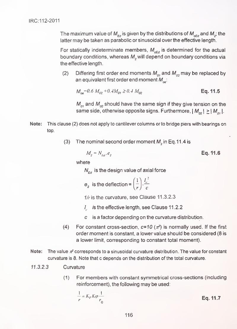
IRC:112-2011
The maximum value of M^^ is given by the distributions of M^^^ and M^, the
latter may be taken as parabolic or sinusoidal over the effective length.
For statically indeterminate members, M^^ is determined for the actual
boundary conditions, whereas will depend on boundary conditions via
the effective length.
(2) Differing first order end moments M^^ and M^^ may be replaced by
an equivalent first order end moment M^:
M^=0.6M,,+0.4Mo,>0.4M,, ,
'
Eq.11.5
Mq, and should have the same sign if they give tension on the
same side, otherwise opposite signs. Furthermore,|M^^
I - \^oi\-
Note: This clause (2) does not apply to cantilever columns or to bridge piers with bearings on
top.
(3) The nominal second order moment ^2 in Eq.1 1.4 is
K = ^,u-^2 Eq.11.6
where
N^^ is the design value of axial force
(-]is the deflection =
1/r is the curvature, see Clause 1 1 .3.2.3
/. is the effective length, see Clause 1 1 .2.2
c is a factor depending on the curvature distribution.
(4) For constant cross-section, c=10 {t^) is normally used. If the first
order moment is constant, a lower value should be considered (8 is
a lower limit, corresponding to constant total moment).
Note: The value corresponds to a sinusoidal curvature distribution. The value for constant
curvature is 8. Note that c depends on the distribution of the total curvature.
11.3.2.3 Curvature
(1) For members with constant symmetrical cross-sections (including
reinforcement), the following may be used:
I ,^ I- = k,K(p— Eq.11.70
116
IRC:112-2011
where
Kr is a correction factor depending on axial load,
Kcp is a factor for taking account of creep.
d = is the effective depth given in (2)
(2) If all reinforcement is not concentrated on opposite sides, but part
of it is distributed parallel to the plane of bending, d is defined as:
v2y+ 's
- Eq. 11J
where is the radius of gyration of the total reinforcement area.
(3) Kf. in Expression (11.7) should be taken as:
= k-^)/k-^M)^l ' Eq.11.9
where
n =J relative axial force.
N,,j = is the design value of axial force.
n^i is the value of n at maximum moment resistance; the value
0.4 may be used
As/yd
^cfcd
= is the total area of reinforcement.
- is the area of concrete cross-sectionc >
(4) The effect of creep should be taken into account by the following factor:
K^ = \ + P(p^f > 1 Eq.11,10
where
(p^fis the effective creep ratio (defined in 11.2.1)
n = 0.35 +^-— Eq.11.11^ 200 150^
where
A = is the slendemess ratio.
117
IRC:112-2011
11.3.3 Biaxial bending
(1) The general method described in Clause 11.3.1 may also be used
for biaxial bending. Special care should be taken to identify the
section along the member with the critical combination of moments.
(2) For details of the use of simplified methods for biaxial momenttaking second order deformation into account, Clause 8.3.2 may bereferred.
11.4 Lateral Instability of Slender Beam
11.4.1 General
(1 ) Lateral instability of slender beams shall be taken into account where
necessary viz. for precast beams during transport and erection
and for beams without sufficient lateral bracing in the construction
stage and in the completed structure. Geometric imperfections shall
also be taken into account.
(2) A lateral deflection of / / 300 should be assumed as a geometric
imperfection in the verification of beams in unbraced conditions,
with / = total length of beam. In finished structures, bracing from
connected members may be taken into account
(3) Second order effects in connection with lateral instability may be
ignored if the following conditions are fulfilled:
h. ^ 30-In persistent situations:
[hlbf^and/7/b<2.5 Eq. 11.12
- In transient situations: ^ ~{hlbj'^
and h/b <3.5 Eq. 11.13
01
where
Is the distance between torsional restraints
h is the total depth ofbeam in central part of I
b is the effective width ofcompression flange
(4) Torsion associated with lateral instability should be taken into
account in the design of supporting structures.
11 .4.2 Slenderness limits for beams
To ensure lateral stability, a simply supported or continuous beam should be so proportioned
118
IRC:112-2011
that the clear distance between lateral restraints does not exceed 60 b„ or , 250 —-® h
whichever is the lesser,
where
h is the effective depth to tension reinforcement.
b is the breadth of the compression face of the beam midway between
restraints.
For cantilevers with lateral restraint provided only at the support, the clear distance from
100the free end of the cantilever to face of the support should not exceed 25b or —-—
,
whichever is the lesser.
119
IRC:112-2011
SECTION 12 SERVICEABILITY LIMIT STATE
12.1 General
(1) In order to verify that the structure and structural elements
perform adequately during service life. The serviceability limit
states shall have to be satisfied. The serviceability limit
states are:-
- Stress level'
- Crack width
- Deflection
Other limit states such as vibration may be of importance in a particular
structure, but are not covered in this Section.
(2) In calculation of stresses and deflection, the cross-section shall be
assumed as uncracked provided tensile stress in concrete does
not exceed /^^ or f^^ and/ci^lculation of minimum tension
reinforcement is also based on the same value of / or/, „ Where
tensile stresses exceed r or /, „ cross-section shall be-' ctm ctm tl
considered as cracked.
12.2 Stress Limitation
12.2.1 Allowable compressive stress in concrete
(1 ) Maximum compressive stress in concrete under rare combinations
of loads shall be limited to 0.48.4, order to keep the longitudinal
cracks, micro cracks or creep within acceptable limits.
(2) Where compressive stress in concrete under quasi-permanent
loads is within 0.36 J[^, linear creep may be assumed. In case
compressive stress exceeds 0.36 non-linear creep shall be
considered, for which AnnexureA-2 may be referred.
12.2.2 Aliovy/able tensile stress in steel
In order to avoid inelastic strain and undesirable cracking/deformation of structure,
maximum tensile stress (taking due account of long term creep of concrete) in the
reinforcement shall be limited to O.Qf^^ under rare combination of loads. For prestressing
steel, in order to avoid inelastic strain, limits prescribed in Clause 7.9.2 shall be
adhered to.
120
IRC:112-2011
12.3 Limit State of Cracking
12.3.1 General
Cracking takes place in tensile regions of concrete structures due to load effects, such as
bending, shear, torsion and direct tension. Cracks may also be caused due to internal
deformations such as shrinkage and temperature effects. The intent of the following
provisions is to ensure, with acceptable probability, that the cracks will not impair the proper
functioning or durability ofthe structure or cause its appearance to be unacceptable. Cracks
due to other effects such as expansive chemical reactions need to be controlled by
measures given under Section 14-r
"
12.3.2 Limiting crack width
(1 ) Due to the random nature of the cracking phenomenon, actual crack
width cannot be predicted. However, a reasonable estimation of
crack width can be made using the mathematical model given in
Clause 12.3.4. The crack width, so calculated, shall be restricted
to the values given in Table 12.1 for various conditions of exposure.
The decompression limit check requires that no tensile stresses
occur within 1 00mm of the surface of duct for bonded prestressing
tendons.
(2) For the crack width checks under combinations which include
temperature distribution, the resulting member forces should be
calculated using gross section concrete properties. The effect of
self-equilibrating thermal stresses within a section may be ignored.
(3) For members with only unbonded tendons, requirements for
reinforced concrete elements apply. For members with a
combination of bonded and unbonded tendons, requirements for
prestressed concrete members with bonded tendons apply.
(4) Crack width may be calculated according to Clause 12.3.4.
Alternatively, limiting maximum bar size or spacing as per
Clause 12.3.6 may be deemed to satisfy crack control criteria for
reinforced concrete members.
121
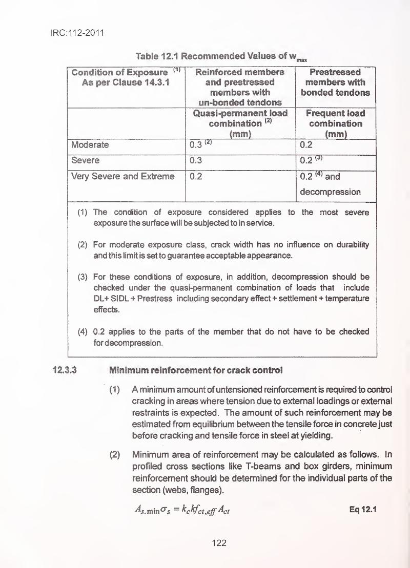
IRC:112-2011
Table 12.1 Recommeocled Values of w^^
wWliyilllOri Of CAflvlSUro
As per Clause 14.3.1 and prestressed
members with
un-bonded tendons
members with
bonded tendons
Quasi-permanent load
combinationImml111 II III
Frequent load
combinationImm)
Moderate 0.3 0.2
Severe 0.3 0.2
Very Severe and Extreme 0.2 0.2 w and
decompression
(1) The condition of exposure considered applies to
exposure the surface will be subjected to in sen/ice.
the most severe
(2) For moderate exposure class, crack width has no influence on durability
and this limit is set to guarantee acceptable appearance.
(3) For these conditions of exposure, in addition, decompression should be
checked under the quasi-permanent combination of loads that include
DL+ SIDL Prestress including secondary effect + settlement + temperature
effects.
(4) 0.2 applies to the parts of the member that do not have to be checked
for decompression.
1 2.3.3 Minimum reinforcement for crack control
(1) A minimum amount of untensioned reinforcement is required to control
cracking in areas where tension due to external loadings or extemal
restraints is expected. The amount of such reinforcement may be
estimated from equilibrium between the tensile force in concrete just
before cracking and tensile force in steel at yielding.
(2) Minimum area of reinforcement may be calculated as follows. In
profiled cross sections like T-beams and box girders, minimum
reinforcement should be determined for the individual parts of the
section (webs, flanges).
^s.mm^s = K¥ct,eff^ct Eq 12.1
122
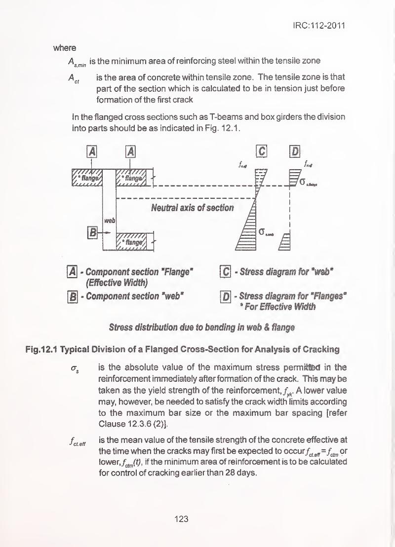
IRC:112-2011
where
\mm minimum area of reinforcing steel within the tensile zone
A , is the area of concrete within tensile zone. The tensile zone is thatcr
part of the section which is calculated to be in tension just before
formation of the first crack
In the flanged cross sections such as T^beams and box girders the division
into parts should be as indicated in Fig. 12.1.
ai
m 1
Neutral axis ofsectlon
0] - Component section 'Flange'
(Effective Width)
[Bj - Component section 'web'
[C] - Stress diagram for 'web'
[D] - Stress diagram for 'Flanges'
* For Effective Width
Stress distribution due to bending in web & flange
Fig.12.1 Typical Division of a Flanged Cross-Section for Analysis of Cracking
<T^ is the absolute value of the maximum stress permed in the
reinforcement immediately after formation ofthe crack. This may betaken as the yield strength of the reinforcement, A lower value
may, however, be needed to satisfy the crack width limits according
to the maximum bar size or the maximum bar spacing [refer
Clause 12.3.6 (2)].
fa effis the mean value of the tensile strength of the concrete effective at
the time when the cracks may first be expected to occur/^^=/^ or
lower,/^ff;, if the minimum area of reinforcement is to be calculated
for control of cracking earlier than 28 days.
123
IRC:112-2011
In calculating the minimum reinforcement to cater for shrinkage/^^^should
be taken as the greater of 2.9 MPa orf^^ (t).
k is the coefficient vyhich allows for the effect of non-uniform self-
equilibrating stresses, which lead to a reduction of restraint forces
= 1.0 for webs with h < 300 mm or flanges with widths less than
300 mm
= 0.65 forwebs with h > 800 mm or flanges with widths greater than
800 mm.
Intermediate values may be interpolated
is a coefficient which takes account of the stress distribution within
the section just prior to cracking and of the change of the lever arm:
For pure tension = 1 .0 . .
For bending or bending combined with axial forces:
- For rectangular sections and webs of box sections and T-sections:
c
where
kc = 0.4 1. Eq.12.2
k] (h/h*) fci^eff
- For flanges of box sections and T-sections:
A,=0.9—L>0.5Eq.12.3
^Ci Jct^eff
is the mean stress of the concrete acting on the part of the section
under consideration:
N^^ is the axial force at the serviceability limit state acting on the part of
the cross-section under consideration (compressive force positive).
iV^j should be determined under the relevant combination of actions
considering the characteristic value of prestress and axial forces.
Is a coefficient considering the effects of axial forces on the stress
distribution:
= 1.5 if A^£^ is a compressive force
124
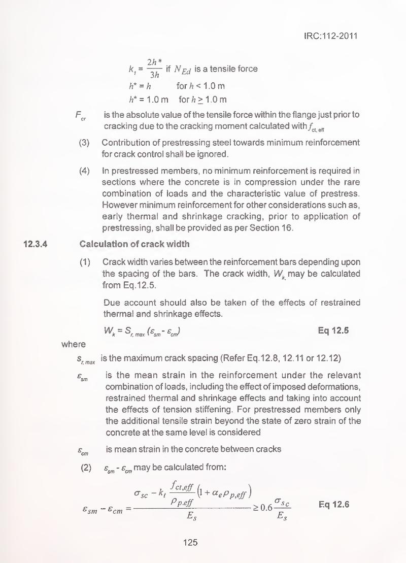
IRC:112-2011
2h*if 7V£j is a tensile forcek =
3/2
for/i < 1.0 m/i* = 1.0m for /i> 10 m
is the absolute value of the tensile force within the flange just prior to
cracking due to the cracking moment calculated with
(3) Contribution of prestressing steel towards minimum reinforcement
for crack control shall be ignored.
(4) In prestressed members, no minimum reinforcement is required in
sections where the concrete is in compression under the rare
combination of loads and the characteristic value of prestress.
However minimum reinforcement for other considerations such as,
early thermal and shrinkage cracking, prior to application of
prestressing, shall be provided as per Section 16.
Calculation of crack width -
;
-
(1 ) Crack width varies between the reinforcement bars depending upon
the spacing of the bars. The crack width, may be calculated
from Eq.12.5.
Due account should also be taken of the effects of restrained
thermal and shrinkage effects.
^r.max'S the maximum crack spacing (Refer Eq.12.8, 12.11 or 12.12)
combination of loads, including the effect of imposed deformations,
restrained thermal and shrinkage effects and taking into account
the effects of tension stiffening. For prestressed members only
the additional tensile strain beyond the state of zero strain of the
concrete at the same level is considered
is mean strain in the concrete between cracks
(2) € - s may be calculated from
:
Eq 12.6
where
£.smis the mean strain in the reinforcement under the relevant
ssmEq 12.6
125
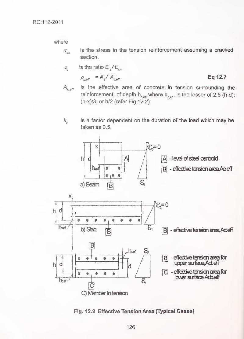
IRC:112-2011
where
$cis the stress in the tension reinforcement assuming a cracked
section.
a Is the ratio EVEs cm
Eq 12.7
ceffis the effective area of concrete in tension surrounding the
reinforcement, of depth h^^^ where \\^^^, is the lesser of 2.5 (h-d);
(h-x)/3; or h/2 (refer Fig.12.2).
is a factor dependent on the duration of the load which may be
taken as 0.5.
§ t.
tiffX
a) Beam [§
[A|- level of steel oentroid
[B| -€fliec&vetension sreaA^efT
"82=0
b)aab rg ^ [§ -effiecbve tension areaA^eff
1h:ef ^
[BI ™dfective tension area for
i|)persurf5aoeAlelT
Q -orecuve tension area lor
lcwversur1iaoeAi>.€ff
C)M8nnber in tension
Fig. 12.2 Effective Tension Area (Typicai Cases)
126
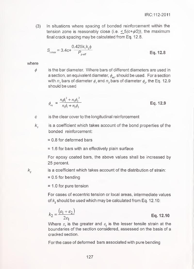
IRC:112-2011
(3) In situations where spacing of bonded reinforcement within the
tension zone is reasonably close (i.e. <S(c^<f^2}}, the maximum
.final crack spacing may be calculated from Eq. 12.8.
^--'*'"^:7~ Eq.12.8
where
^ is the bar diameter Where bars of different diameters are used in
a section, an equivalent diameter, should be used. For a section
with bars of diameter and bars of diameter the Eq. 12.9
should be used
# = —T~—J~ . .Eq. 12.9
c is the clear cover to the longitudinal reinforcement
is a coefficient which takes account of the bond properties of the
bonded reinforcement:
^0.8 for deformed bars '
.
'
= 16 for bars with an effectively plain surface
For epoxy coated bars, the above values shall be increased by
25 percent.
IS a coefficient which takes account of the distribution of strain:
= 0.5 for bending
= 10 for pure tension ,; ^
For cases of eccentric tension or local areas, intermediate values
of ^2 should be used which nnay be calculated from Eq. 12.10:
Where is the greater and <s the lesser tensile strain at the
boundaries of the section considered, assessed on the basis of a
cracked section.
For the case of deformed bars associated with pure bending
127
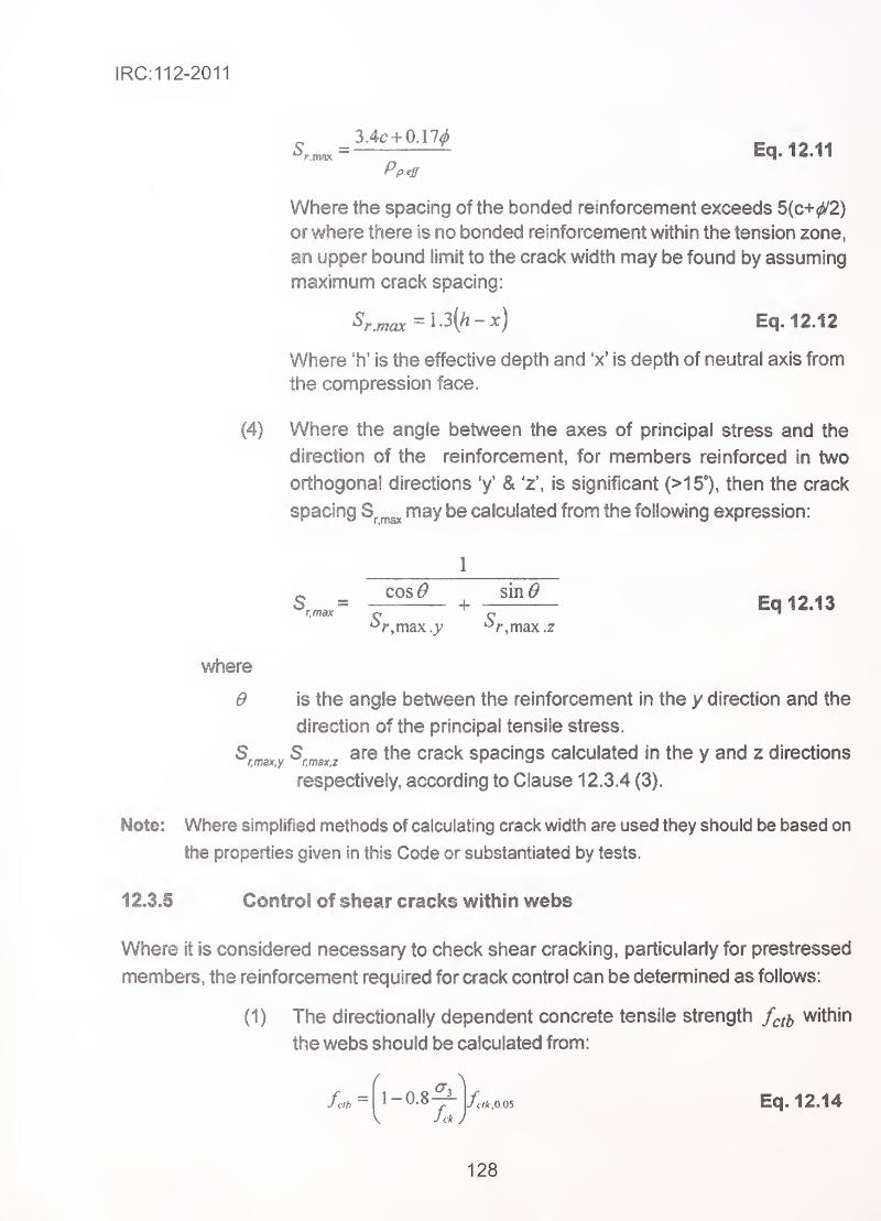
IRC:112-2011
S.^=^^^^ Eq.12.11Pp.eff
Where the spacing of the bonded reinforcement exceeds 5(c+^2)
orwhere there is no bonded reinforcement within the tension zone,
an upper bound limit to the crack width may be found by assuming
maximum crack spacing:
Sr^^^^l3{h-x) Eq. 12.12
Where 'h' is the effective depth and x' is depth of neutral axis from
the compression face.
(4) Where the angle between the axes of principal stress and the
direction of the reinforcement, for members reinforced in two
orthogonal directions 'y' & 'z'. is significant (>15°), then the crack
spacing ^ may be calculated from the following expression:
1
o cos^ sin^ ' _S^^^= — + Eq 12.13
•^r,max .y '^r,max .z
where
0 is the angle between the reinforcement In the y direction and the
direction of the principal tensile stress.
^r.maxy ^r.maxzthe crack spaclngs calculated in the y and z directions
respectively, according to Clause 1 2.3.4 (3).
Note: Where simplified methods of calculating crack width are used they should be based on
the properties given in this Code or substantiated by tests.
12.3.5 Control of shear cracks within webs
Where it is considered necessary to check shear cracking, particularly for prestressed
members, the reinforcement required for crack control can be detemiined as follows:
(1) The directionally dependent concrete tensile strength f^tb within
the webs should be calculated from:
fclh~ 1-0.8
V fck Jfcik,Q.Q5 Eq. 12.14
128
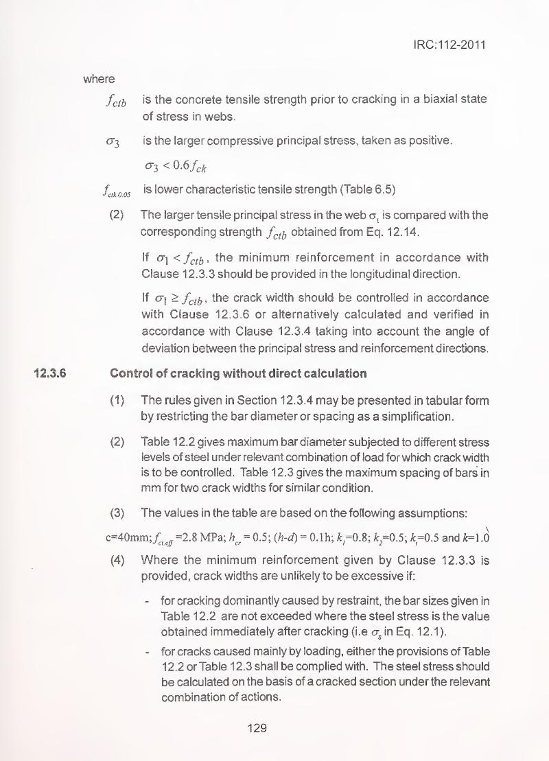
IRC:112-2011
where
. fcijy is the concrete tensile strength prior to cracking in a biaxial state
of stress in webs.
£73 is the larger compressive principal stress, taken as positive.
'
fctko.05lower characteristic tensile strength (Table 6.5)
(2) The larger tensile principal stress in the web is compared with the
corresponding strength f^^^ obtained from Eq. 12.14.
If 0"| < /^^^, the minimum reinforcement in accordance with
Clause 12.3.3 should be provided in the longitudinal direction.
if ai >f^^iy , the crack width should be controlled in accordance
with Clause 12.3.6 or alternatively calculated and verified in
accordance with Clause 12.3.4 taking into account the angle of
deviation between the principal stress and reinforcement directions.
Control of Grackfng without direct calculation
(1) The rules given in Section 12.3.4 may be presented in tabular form
by restricting the bar diameter or spacing as a simplification.
(2) Table 1 2.2 gives maximum bar diameter subjected to different stress
levels of steel under relevant combination of load for which crack width"
is to be controlled. Table 12.3 gives the maximum spacing of bars in
mm for two crack widths for similar condition.
(3) The values in the table are based on the following assumptions:
c=40mm;4^^ =2.8 MPa; = 0.5; (h-d) = O.lh; A: =0.8; ^^=0.5; ^=0.5 and k=\.0
(4) Where the minimum reinforcement given by Clause 12.3.3 is
provided, crack widths are unlikely to be excessive if:
- for cracking dominantly caused by restraint, the bar sizes given in
Table 12 .2 are not exceeded where the steel stress is the value
obtained immediately after cracking (i.e in Eq. 12.1).
- for cracks caused mainly by loading, either the provisions of Table
12.2 or Table 12.3 shall be complied with. The steel stress should
be calculated on the basis of a cracked section under the relevant
combination of actions.
129
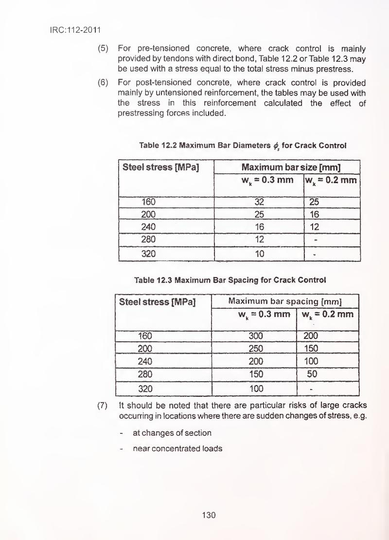
For pre-tensioned concrete, where crack control Is majniy
provided by tendons with direct bond, Table 12.2 or Table 12.3 maybe used with a stress equal to the total stress minus prestress.
For post-tensioned concrete, where crack control is provided
mainly by untensioned reinforcement, the tables may be used with
the stress in this reinforcement calculated the effect of
prestressing forces included.
Table 12.2 Maximum Bar Diameters for Crack Control
Steel stress [MPa] Maximum bar size [mm]
Wj^ = 0.3 mm w,^ = 0.2 mm
160 32
200 25 16
240 16 12
280 12 INK-
320 10
Table 12.3 Maximum Bar Spacing for Crack Control
Steel stress [MPa] Maximum bar spacing [mm]
= 0.3 mm = 0.2 mm
160 300 200
200 1^240 200 100
280 150 50
320 100
It should be noted that there are particular risks of large cracks
occurring in locations where there are sudden changes of stress, e.g.
- at changes of section
- near concentrated loads
130
IRC:112-2011
- at positions where bars are curtailed
- at areas of high bond stress, particularly at the ends of laps
Care should be taken at such locations to minimize the stress changes
wherever possible However, the rules for crack control given above
will normally ensure adequate control at these points provided that
the rules for detailing reinforcement given in Section 16 are
complied with.
12.4 Limit State of Deflection
12.4.1 General
Cable supported bridges are not in the purview of this Code, for which specialist literature
may be followed.
(1 ) The deflections/deformations of a member or structure shall not be
such that it adversely affects its proper functioning or appearance.
In some cases, expected deflections may need to be adjusted in
the structural geometry by pre-cambering, so as to attain the
requisite profile at the time of placing expansion joints and wearing
course.
(2) Appropriate limiting values of deflection taking into account the
nature of the structure, bridge deck furniture and functional needs
of the bridge, should be established. In the absence of other criteria,
the following deflection limits under Live Load may be considered
Vehicular : Span/800,
Vehicular and pedestrian or : Span/1000,
pedestrian alone
Vehicular on cantilever : Cantilever Span/300, and
Vehicular & pedestrian and : Cantilever Span/375
pedestrian only on cantilever
arms
12.4.2 Calculation of deflection due to sustained loads
(1 ) The calculation method adopted shall represent the true behaviour
of the structure under relevant actions with accuracy appropriate to
the objectives of the calculation. In case of cracked members,
131
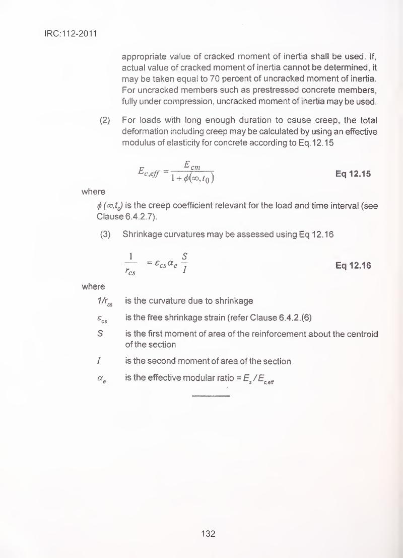
IRC:112-2011
appropriate value of cracked moment of inertia shall be used. If,
actual value of cracked moment of inertia cannot be determined, it
may be taken equal to 70 percent of uncracked moment of inertia.
For uncracked members such as prestressed concrete members,
fully under compression, uncracked moment of inertia may be used.
(2) For loads with long enough duration to cause creep, the total
deformation including creep may be calculated by using an effective
modulus of elasticity for concrete according to Eq.12.15
'^•^^^"l + ^K/o)Eq 12.15
where
^(oo,tj is the creep coefficient relevant for the load and time interval (see
Clause 6.4.2.7).
(3) Shrinkage curvatures may be assessed using Eq 12.16
1 S— = ^cs^e 7 - - Eq 12.16^cs ^
where
is the curvature due to shrinkage
is the free shrinkage strain (refer Clause 6.4.2.(6)
S is the first moment of area of the reinforcement about the centroid
of the section
/ is the second moment of area of the section
a. is the effective modular ratio = E /E „9 s ceft
132
IRC:112-2011
SECTION 13 PRESTRESSING SYSTEMS
13J General
This Section covers requirements of the parts of prestressing systems which are
incorporated in the structure. Prestressing systems manufactured by specialist
manufacturers shall be compatible with the standard prestressing wires/strands covered
in Section 6. The stressing equipment, de-stresslng/re-stressing facilities, and grouting
an^angements shall be compatible with the tendons.
13.2 Anchorages for Post Tensioning Systems
13.2.1 ' Anchorages to be used
Following types of anchorages normally used in bridges shall meet the minimumrequirements given in this Section.
(1) Anchorages partially or fully embedded in concrete in which the
prestressing force is transferred within the body of the prestressed
element by combination of bearing, friction and wedge action.
(2) Externally mounted anchorages which transfer prestressing force
of tendons to concrete through a bearing plate which is extemally
mounted.
(1 ) The anchorage device should be capable of holding and transfemng
force of not less than 95 percent of the actual mean tensile ultimate
strength of the tendons it is expected to hold, without failure of any
of the parts of the anchorage-tendon assembly.
(2) The anchorage tendon assembly shall be capable of withstanding
not less than two million cycles of fatigue load varying between
60 percent to 65 percent of nominal UTS of tendons It is expected
to hold, without suffering more than 5 percent breakage of wires/
strands at the load frequency of not more than 500 cycles per
minute.
The end block is the portion of the concrete element through which the concentrated load
applied at anchorages is transmitted to the whole cross section of the element. The concrete
and the reinforcement in this region shall be designed to transfer load not less than
13.2.2 Minimum requirements of anchorage capacity
13.2.3 Load transfer to concrete element through end block
133
IRC:112-2011
110 percent of nominal UTS of tendons it is expected to hold. The crack width shall not
exceed 0.25 mm at 80 percent of UTS.
13.2.4 Acceptance tests for anchorage-tendon assembly
The anchorage-tendon assemblies shall comply with the following acceptance tests as
per FIP "Recommendations for the acceptance of post-tensioning systems" - (June 1 993).
(1) Static load test with tendon-anchorage.
(2) Dynamic load test with tendon-anchorage assembly. /
(3) Load transfer test.
13.3 Mechanical Couplers
Mechanical couplers of fixed or movable type are devices in which individual lengths of
tendons are anchored in two collinear directions to form one continuous tendon. The
couplers shall meet the requirements of strength of individual anchorages as specified
in Clause 13.2, and be able to transfer full force of tendon from one to another. The
anchorage and stressing of second tendon should not disturb the anchorage of the first
tendon in case of fixed couplers.
13.4 Sheathing Ducts and Joints
The sheathing ducts shall be either in mild steel as per Clause 1 3.4.2 or in HOPE as per
Clause 13.4.3. They shall be in as long lengths as practicable from handling and
transportation considerations without getting damaged. The internal joints ofthe duct lengths
shall be watertightwhen bent to the minimum radius of bending required in the structure as
specified in Clause 13.4.1 (2).
13.4.1 Common requirements ofjoints of sheathing
(1) The ducts lengths shall be joined by adopting any one or more of
the following methods as convenient to suit the individual
requirements of the location, subject to satisfactory pressure
tests, before adoption.
- Using corrugated threaded sleeve couplers which can be tightly
screwed to the outside of the sheathing ducts.
- Integrating the two ends by welding using electric roaster
machine or mirror machine.
- Using heat shrink couplers.
134
IRC:112-2011
(2) The sheathing ducts and connections should be fully leak-tight
against water pressure equivalent to 1.1 x (maximum expected
gravity head of grouting material + grouting pressure). The joints
should also be leak-tight and pressure resistant for above pressure.
(3) External tendons shall be housed in either High Density Poly-
Ethylene (HOPE) sheaths or metallic steel sheaths (plain or with
protective coatings), which have smooth internal surfaces.
M.S. sheathing ducts
(1) Unless otherwise specified, the material shall be Cold Roiled Cold
Annealed (CRCA) Mild Steel intended for mechanical treatment
and surface refining but not for quench hardening or tempering.
(2) The material shall be clean and free from rust and nomially of bright
metal finish. However, in case of use in aggressive environment
galvanised or lead coated mild steel strips shall be adopted.
(3) The thickness of metal sheathing shall not be less than 0.3 mm,
0.4 mm and 0.5 mm for sheathing ducts having internal diameter
upto 50 mm, 75 mm and 90 mm and above respectively. For larger
diameter ducts, thickness of sheathing shall be based on
recommendations of prestressing system supplier.
Corrugated HOPE sheathing ducts
(1) The material for the ducts shall be high density polyethylene with
more than 2 percent carbon black to provide resistance to ultraviolet
degradation. Properties of raw materials shall comply with the
technical report Bulletin 7 published by FIB "Corrugated plastic ducts
for internal bonded post tensioning"
(2) The wall thickness of the duct as manufactured shall be 2.0 mm,
2.5 mm, 3.0 mm, and 4.0 mm for ducts of internal diameter up to
50 mm, 85 mm, 100 mm and 125 mm respectively. The minimum
residual wall thickness after loss (wear resistance) shall not be less
than 1.5 mm for ducts upto 85 mm in diameter and not less than
2 mm for ducts greater than 85 mm in diameter.
(3) The ducts shall be corrugated on both sides. The ducts shall transmit
full tendon strength from the tendon to the surrounding concrete
over a length not greater than 40-ducts' diameters.
135
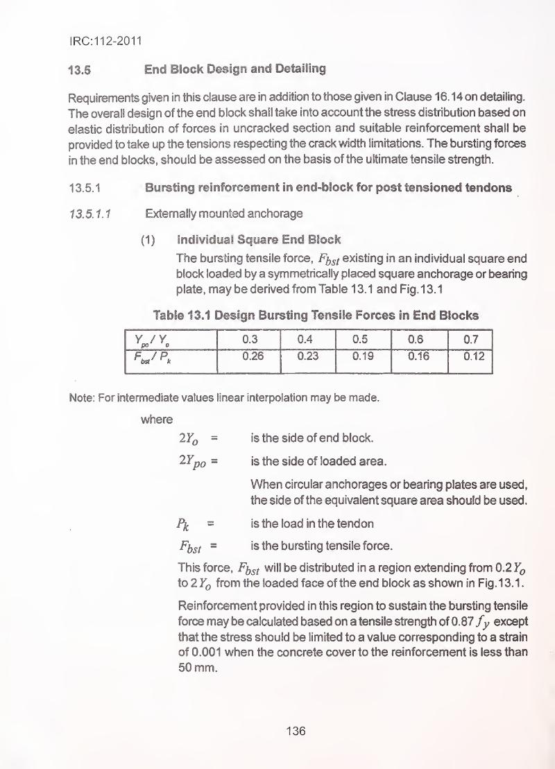
IRC:112-2011
13.5 . End Block Design and Detailing
Requirements given in this clause are in addition to those given in Clause 16.14 on detailing.
The overall design of the end block shall take into account the stress distribution based on
elastic distribution of forces in uncracked section and suitable reinforcement shall be
provided to take up the tensions respecting the crack width limitations. The bursting forces
in the end blocks, should be assessed on the basis ofthe ultimate tensile strength.
13.5.1 Bursting reinforcement in end-block for post tensioned tendons
13.5.1.1 Externally mounted anchorage _
(1) Individual Square End Block
The bursting tensile force, Ff^gf existing in an individual square end
block loaded by a symmetrically placed square anchorage or bearing
plate, may be derived from Table 13.1 and Fig. 13.1
Table 13J Design Bursting Tensile Forces In End Blocks
0.3 0.4 0.5 0.6 0.7
0.26 0.23 0.19 0.16 0.12
Note: For intermediate values linear interpolation may be made,
where
2F^ = is the side of end block.
2Yp0 = is the side of loaded area.
When circular anchorages or bearing plates are used,
the side ofthe equivalent square area should be used.
I\ = is the load in the tendon
^bsi" is the bursting tensile force.
This force, will be distributed in a region extending from 0.2
to 2 Yq from the loaded face of the end block as shown in Fig. 13.1.
Reinforcement provided in this region to sustain the bursting tensile
force may be calculated based on a tensile strength of 0.87 fy except
that the stress should be limited to a value corresponding to a strain
of 0.001 when the concrete cover to the reinforcement is less than
50 mm.
136
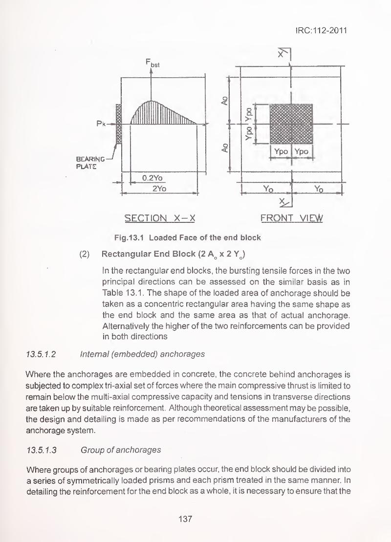
IRC:112-2011
BEARINGPL/TE
SECTION FRONT VIEW
FigJSJ Loaded Face of the end block ,
'
(2) Rectangular End Block (2 X 2 YJ
In the rectangular end blocks, the bursting tensile forces in the two
principal directions can be assessed on the similar basis as in
Table 13.1. The shape of the loaded area of anchorage should be
taken as a concentric rectangular area having the same shape as
the end block and the same area as that of actual anchorage.
Alternatively the higher of the two reinforcements can be provided
in both directions
13.5.1.2 Internal (embedded) anchorages
Where the anchorages are embedded in concrete, the concrete behind anchorages is
subjected to complex tri-axial set offerees where the main compressive thrust is limited to
remain below the multi-axial compressive capacity and tensions in transverse directions
are taken up by suitable reinforcement. Although theoretical assessment may be possible,
the design and detailing is made as per recommendations of the manufacturers of the
anchorage system.
13.5.1.3 Group ofanchorages
Where groups of anchorages or bearing plates occur, the end block should be divided into
a series of symmetrically loaded prisms and each prism treated in the same manner. In
detailing the reinforcement for the end block as a whole, it is necessary to ensure that the
137
IRC:112-2011
groups of anchorages are appropriately tied together. Special attention should be paid to
end blocks having a cross-section different in shape from that of the general cross-section
of the beam and reference should be made to specialist literature. Compliance with the
above requirements will generally ensure that bursting tensile forces along the loaded axis
are provided for. In case where large concentrated tendon forces are involved alternative
methods of design based on specialist literature and manufacturer's data as per
Clause 13.5.3 may be more appropriate.
1 3.5.2 Spaiting reinforcement for post-tensioned tendons
Consideration should also be given to the spaliing tensile stresses that occur in end blocks.
Where the anchorage or bearing plates are highly eccentric, these stresses reach a
maximum at the loaded face. The end face of anchorage zone shall be continuously
reinforced to prevent edge spelling. Reinforcement shall be placed as close to the end
face as possible.
13.5.3 Bursting reinforcement for pre-tensioned members
The bursting resistance of pre-tensioned anchorage zone provided by vertical reinforcement
in the ends of pre-tensioned beams shall be taken as:
where
fs = stress in steel not exceeding 140 MPa
Ag = Total area of vertical reinforcement located within the distance hi 5
from the end of the beam (mm^).
h = Overall depth ofprecast member (mm)
The bursting resistance Pf. shall not be less than 4 percent of the prestressing force at
transfer.
The end vertical reinforcement shall be as close to the end of the beam as practicable.
13.6 Protective Grouting
(1) Post tensioned tendons shall be bonded to concrete of the
prestressed member as well as protected from corrosion by cement
grout which shall fill the ducts fully, without leaving any entrapped
air or water pockets, voids created by evaporation of excess water
in the grout and bleeding.
(2) Unbonded tendons placed either in ducts embedded in concrete
or externally located shall be protected from corrosion by suitable
138
IRC:112-2011
fillers. Grouting by cement, wax, nuclear grade (low sulphur) grease
are some of the options. For materials other than cement or such
long life permanent materials, arrangements for inspection and''
refilling or replacement of grouting materials shall be made. Factory
made coated wires/strands embedded in polyethylene ducts with
suitable fill are acceptable. Manufacturer's recommendations shall
be followed for the specialist materials and techniques.
13.7 • Protection of Post Tensioned Tendons and Anchorages'
In order to achieve a durable post-tensioning system, matching with the design service life
of the structure, suitable corrosion protection of the post-tensioning system, is necessary.
The con-osion protection system shall take into account: •
(a) Temporary protection of the tendons, ducts, anchorages and all
accessories from manufacturer handling storage, transport till
incorporation in the structure.
(b) Semi-permanent protection of the system in situations where the
tendons and anchorages are exposed to atmosphere for an extended
period of time.
(c) Permanent protection of prestressing system applied either at the
factory or at site shall be according to stressing of the surrounding.
Special care is warranted since most parts of the tendon or other
component are generally not accessible during service life. .
139
IRC:112-2011
SECTION 14 DURABILITY
14.1 General •
.
'
'
This Section covers design for durability and suggests provisions to ensure that adequate
durability is achieved.
The structure shall be designed such that deterioration over its design service life does
not impair the performance of the structure below that intended, having due regard to
the service environment and the anticipated level of maintenance.
One of the main characteristics influencing the durability of concrete is its permeability
to the ingress of water, oxygen, carbon dioxide, chloride, sulphate and other potentially
deleterious substances. Degree of permeability is governed by the constituents, the
mix proportions and workmanship used in making concrete. A suitably low permeability
can be achieved by having adequate cement content, low water cement ratio and
ensuring complete compaction of the concrete followed by adequate curing. Use of
blended cements will also help to achieve low permeability.
The factors influencing durability of concrete include:
(1) The environment,
(2) The cover to embedded steel,
(3) The type and quality of constituent materials,
(4) The cement content and water/cement ratio,
(6) Workmanship to obtain full compaction and efficient curing and
(6) The shape and size of the member.
14.2 Common Mechanisms Leading to the Deterioration of ConcreteStructures •
Common mechanisms of deterioration of concrete structures in service are:
(1) Corrosion of reinforcement/prestressing tendons
(2) Frost attack
(3) Alkali-aggregate reactions
(4) Attack from sulphates
(5) Attack by aggressive chemicals
(6) Acid attack and
(7) Abrasion
Description of the mechanisms is given inAnnexure B-2.
140
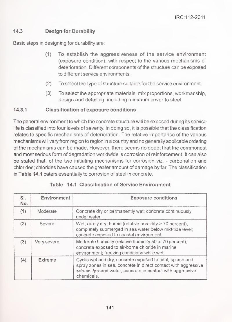
IRC:112-2011
14.3 Design for Durability
Basic steps in designing for durability are:
(1) To establish the aggressiveness of the service environment
(exposure condition), with respect to the various mechanisms of
deterioration. Different components of the structure can be exposed
. ^ to different service environments.
(2) To select the type of structure suitable for the service environment.
(3) To select the appropriate materials, mix proportions, workmanship,
design and detailing, including minimum cover to steel.
14.3.1 Classification of exposure conditions
The general environment to which the concrete structure will be exposed during its service
life is classified into four levels of severity. In doing so, it is possible that the classification
relates to specific mechanisms of deterioration The relative importance of the various
mechanisms will vary from region to region in a country and no generally applicable ordering
of the mechanisms can be made. However, there seems no doubt that the commonest
and most serious form of degradation worldwide is corrosion of reinforcement. It can also
be stated that, of the two initiating mechanisms for corrosion viz. - carbonation and
chlorides; chlohdes have caused the greater amount of damage by far. The classification
in Table 14.1 caters essentially to corrosion of steel in concrete.
Table 14.1 Classification of Service Environment
SI.
No.
Environment Exposure conditions
(1) Moderate Concrete dry or permanently wet; concrete continuously
under water.
(2) Severe Wet, rarely dry; humid (relative humidity > 70 percent),
completely submerged in sea water below mid-tide level;
concrete exposed to coastal environment,
(3) Very severe Moderate humidity (relative humidity 50 to 70 percent);
concrete exposed to air-borne chloride in marine
environment; freezing conditions while wet.
(4) Extreme Cyclic wet and dry, concrete exposed to tidal, splash and
spray zones in sea, concrete in direct contact with aggressive
sub-soil/ground water, concrete in contact with aggressive
chemicals.
141
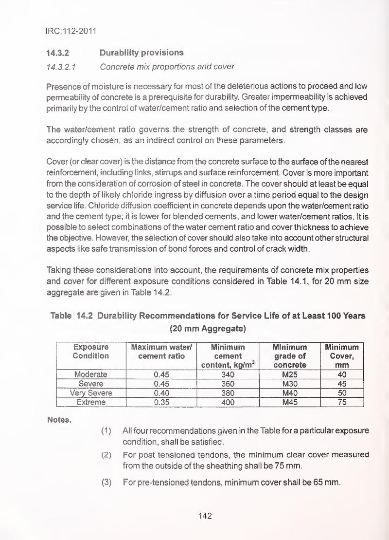
IRC:112-2011
14.3.2 Durability provisions
14.3.2.1 Concrete mix proportions and cover
Presence of moisture is necessary for most of the deleterious actions to proceed and low
permeability of concrete is a prerequisite for durability. Greater impermeability is achieved
primarily by the control of water/cement ratio and seiection of the cement type.
The water/cement ratio governs the strength of concrete, and strength classes are
accordingly chosen, as an indirect control on these parameters.
Cover (or clear cover) is the distance from the concrete surface to the surface of the nearest
reinforrennent, including links, stirrups and surface reinforcement. Cover is more important
from the consideration of corrosion of steel in concrete. The cover should at least be equal
to the depth of likely chloride ingress by diffusion over a time period equal to the design
service life. Chloride diffusion coefficient in concrete depends upon the water/cement ratio
- and the cement type; it is lower for blended cements, and lower water/cement ratios, ft is
- possible to select combinations of the water cement ratio and cover thickness to achieve
the objective. However, the selection of cover should also take into account other structural
aspects like safe transmission of bond forces and control of crack width.
Taking these considerations into account, the requirements of concrete mix properties
and cover for different exposure conditions considered in Table 14.1, for 20 mm size
aggregate are given in Table 14.2,
Table 14.2 Durability Recommendations for Service Life of at Least 100 Years
(20 mm Aggregate)
Exposure Maximum water/ Minimum Minimum MinimumCondition cement ratio cement grade of Cover,
content, kg/m^ concrete mmModerate 0.45 340 M25 40Severe 0.45 360 M30 45
Very Severe 0.40 380 M40 50
Extreme 0.35 400 M45 75
Notes.
(1) All four recommendations given in the Table for a particular exposure
condition, shall be satisfied.
(2) For post tensloned tendons, the minimum clear cover measured
from the outside of the sheathing shall be 75 mm.
(3) For pre-tensioned tendons, minimum cover shall be 65 mm.
142
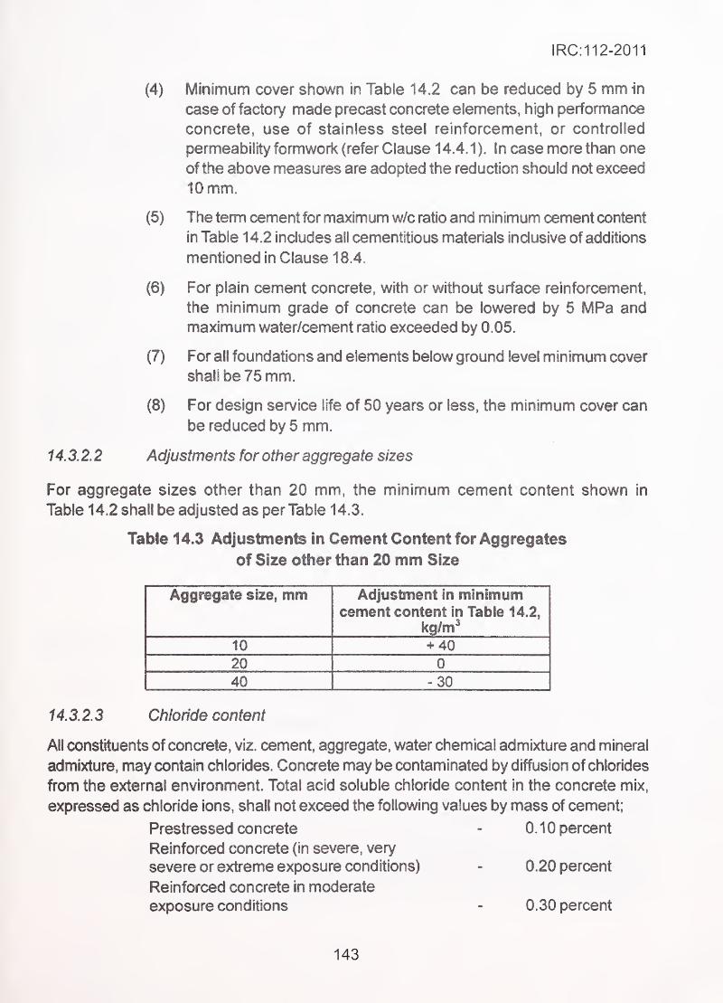
IRC:112-2011
Minimum cover shown in Table 14.2 can be reduced by 5 mm in
case of factory made precast concrete elements, high performance
concrete, use of stainless steel reinforcement, or controlled
permeability fonnwork (refer Clause 14.4.1). In case more than one
ofthe above measures are adopted the reduction should not exceed
10 mm. '
The term cement for maximum w/c ratio and minimum cement content
in Table 14.2 includes all cementitious materials inclusive of additions
mentioned in Clause 18.4.
For plain cement concrete, with or without surface reinforcement,
the minimum grade of concrete can be lowered by 5 MPa and
maximum water/cement ratio exceeded by 0.05.
For all foundations and elements below ground level minimum cover
shall be 75 mm.
For design service life of 60 years or less:, the minimum cover can
be reduced by 5 mm..
^ \ .
14.3.2.2 Adjustments for other aggregate sizes '
For aggregate sizes other than 20 mm, the minimum cement content shown in
Table 14.2 shall be adjusted as per Table 14.3.
Table 14.3 Adjustments in Cement Content for Aggregates
of Size other than 20 mm Size
Aggregate size, mm Adjustment in minimumcement content in Table 14.2,
10 + 40
20 0
40 - 30
14.3.2.3 Chloride content
All constituents of concrete, viz. cement, aggregate, water chemical admixture and mineral
admixture, may contain chlorides. Concrete may be contaminated by diffusion of chlorides
from the external environment. Total acid soluble chloride content in the concrete mix,
expressed as chloride ions, shall not exceed the following values by mass of cement;
Prestressed concrete - 0.10 percent
Reinforced concrete (in severe, very
severe or extreme exposure conditions) - 0.20 percent
Reinforced concrete in moderate
exposure conditions - 0.30 percent
143
(4)
(5)
(6)
(7)
(8)
IRC:112-2011
14.3.2.4 Sulphate content
Sulphates are present in cements, in some aggregates and mix water. They can also be
imbibed from the service environment e.g. coastal environment. The total water-soluble
sulphate content of the concrete mix, expressed as SO3. shall not exceed 4 percent by
mass of cement in the mix.
14.3.2.5 Maximum cement content
Cement content (excluding fly ash, GGBS or Silica Fume) shall not exceed 450 kg/m^.
14.4 Additional Provisions for Specific Mechanisms of Deterioration
Some additional provisions for different mechanisms of deterioration are given below.
14.4.1 Corrosion of reinforcement
The normal way to design against corrosion is to ensure that there is an adequate cover to
the reinforcement and that the concrete in the cover region is of a high quality and is well
cured. In extreme environments, however, there are other measures which may have to be
adopted, such as:
(1) Use of galvanized reinforcement or reinforcement with fusion-
bonded epoxy coating.,
•.
.
;
(2) Use of surface coatings to the concrete to inhibit the ingress of
chlorides or carbon dioxide. Such coatings need periodic
renewal.
(3) Use of waterproofing membrane over the bridge deck.
(4) Use of controlled permeability formwork (CPF) liners, which effectively
reduce the water-cement ratio of cover concrete and reduce the
chloride diffusion into the concrete.
(5) Application of cathodic protection to the structure.
(6) Use of stainless steel reinforcement.
One major factor in the avoidance of corrosion problems is the form of the structure. Areas
of exposed concrete on which water can stand or can drain across, are particularly at risk.
14.4.2 Sulphate attack
Depending upon the concentration of SO3 ions in soil, subsoil or ground water, appropriate
protective measures comprise selection of proper type of cement, mix proportions and
protective coatings in severe cases. The details are given in Table 14.4.
144
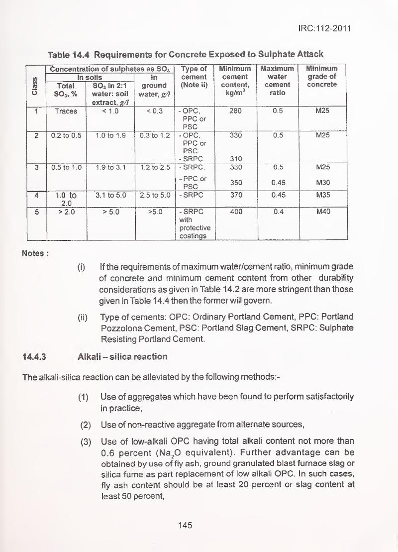
IRC:112-2011
Table 14.4 Requirements for Concrete Exposed to Sulphate Attack
i
Concentration of sulpha tes as SO3 Type of
cement(Note 11)
Minimumcementcontent,
kg/m*
Maximumwatercementratio
Minimumgrade ofconcrete
In soils In
groundwater, g/l
Total
%SO3 In 2:1
water: soli
extract, g/1
1 Traces < 1.0 <0.3 -OPC.PPC orpep
280 0.5 M25
2 0.2 to 0.5 1.0 to 1.9 0.3 to 1.2 -OPC,ppp or
PSC-SRPC
330
310
0.5 M25
3 0.5 to 10 1.9 to 3.1 1.2 to 2 .5 -SRPC.
- PPC or
PSC
330
350
0.5
0.45
M25
M30
4 1.0 to
2.0
3.1 to 5 0 2.5 to 5.0 -SRPC 370 0.45 M35
5 >2.0 >5.0 >5.0 -SRPCwith
protective
coatings
400 0.4 M40
Notes
:
(i) if the requirements of maximum water/cement ratio, minimum grade
of concrete and minimum cement content from other durability
considerations as given in Table 1 4.2 are more stringent than those
given in Table 14.4 then the former will govern.
(if) Type of cements: OPC: Ordinary Portland Cement, PPC: Portland
Pozzolona Cement, PSC: Portland Slag Cement, SRPC: Sulphate
Resisting Portland Cement.
14.4.3 Alkali -silica reaction
The alkali-silica reaction can be alleviated by the following methods:-
(1) Use of aggregates which have been found to perform satisfactorily
in practice,1
(2) Use of non-reactive aggregate from alternate sources,
(3) Use of iow-alkali OPC having total alkali content not more than
0.6 percent {Hafi equivalent). Further advantage can be
obtained by use of fly ash, ground granulated blast furnace slag or
silica fume as part replacement of low alkali OPC. In such cases,
fly ash content should be at least 20 percent or slag content at
least 50 percent,
145
IRC:112-2011
(4) Measures to reduce the degree of saturation of concrete during
service such as use of impermeable membranes,
(5) Limiting the cement content of the concrete mix and thereby limiting
total alkali content in the concrete mix,
For more guidance, specialist literature may be referred.
14.4.4 Frost attack
Frost damage can be avoided by the following methods:-
(1) Protecting the concrete from saturation.
(2) Using an air-entrained concrete mix. The small bubbles of entrained
air within the matrix can provide pressure relief. The minimum
amount of entrained air should be 3.5 percent for 20 mm size
aggregate, and greater for smaller sizes. Air-entraining admixture
should conform to IS 91 03.
(3) Using high-strength concrete, with compressive strength of45 MPaor more.
146
IRC:112-2011
SECTION 16 DETAILING: GENERAL REQUIREMENTS
15.1 General
(1) The following detailing requirements apply to ail structures
using normal weight concrete, uncoated steel for reinforcement and
prestressing. These are supplemented for specific applications by
additional rules in Sections 16 & 17.
(2) Modifications in provisions required for use of coated steels are
given in Clause 15.4.
15.2 Reinforcing Steel
15.2.1 Spacing of bars
(1) The spacing of bars shall be such that the concrete can be placed
and compacted satisfactorily for the development of adequate bond.
The aggregate size, shall be chosen to permit adequate
compaction around the bars where is the nominal size as per
18383.
(2) The clear distance, (horizontal and vertical) between individual
parallel bars or horizontal layers of parallel bars shall not be less
than maximum of (a) largest bar diameter (b) (d^ + 10 mm) or
(c) 20 mm.
(3) Where bars are positioned in separate horizontal layers, the bars
in each layer should be located vertically above each other. Where
access for vibrator needle is required, the spacing between columns
of bars shall not be less than 50 mm.
(4) Lapped bars may touch one another within the lap length.
15.2.2 Permissible bending
The minimum bend diameter of the bar shall be such as to avoid bending cracks in the bar
and crushing or splitting of the concrete inside the bend.
The minimum diameter of the mandrel used for bending should be not less than the values
given in Tables 15.1 & 15.2.
147
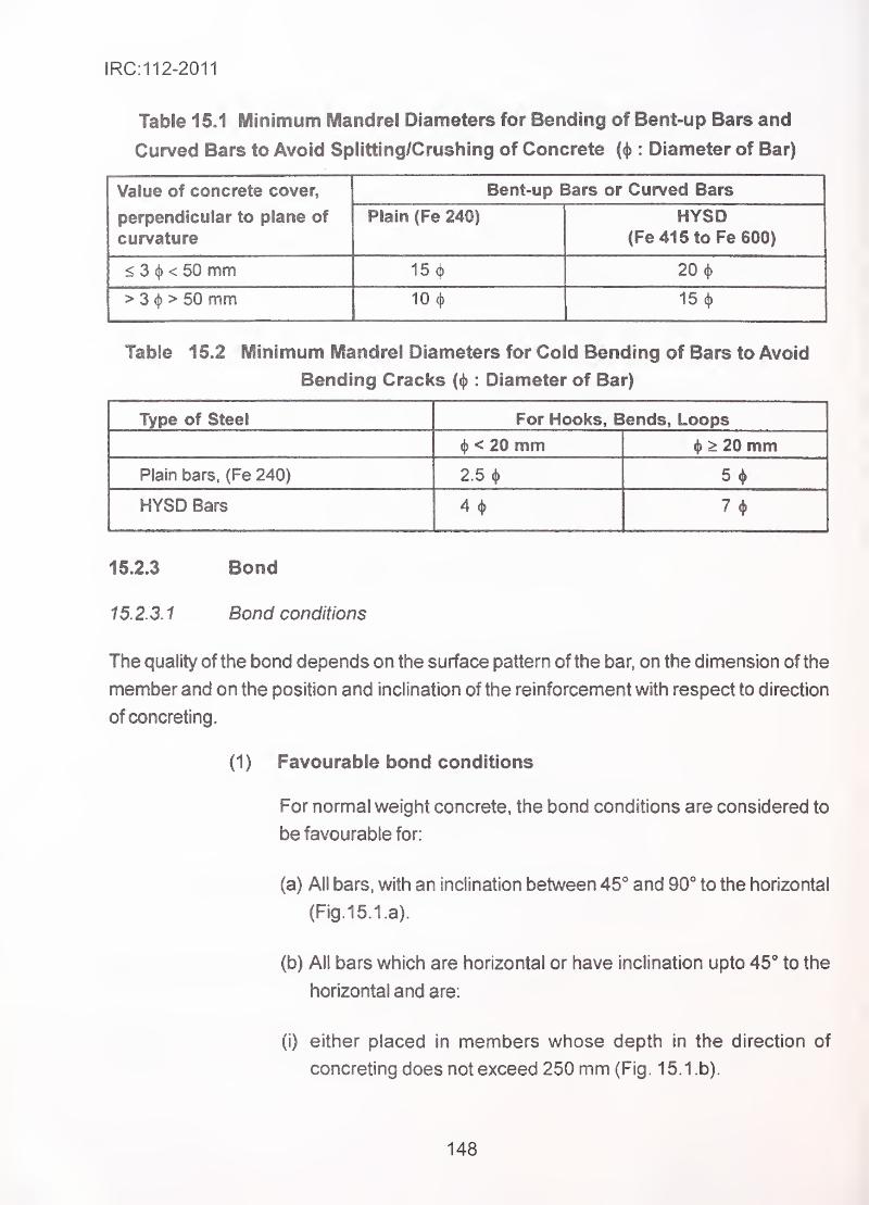
IRC:112-2011
Table Minimum IVIandrel Diameters for Bending of Bent-up Bars and
Curved Bars to Avoid Splitting/Crushing of Concrete (<|> : Diameter of Bar)
Value of concrete cover,
perpendicular to plane of
curvature
Bent-up Bars or Curved Bars
Plain (Fe 240) HYSD(Fe 41 5 to Fe 600)
< 3 (j)< 50 mm 15 <j) 20 4>
> 3 <j) > 50 mm 10 <|) 15 (j)
Table 15.2 Minimum Mandrel Diameters for Cold Bending of Bars to Avoid
Bending Cracks : Diameter of Bar)
Type of Steel For Hooks, Blends, Loops
<j) < 20 mm i|> ^ 20 mmPlain bars, (Fe 240) 2.5 4>
HYSD Bars 4* 7(j>
15.2.3 Bond
1 5. 2. 3. 1 Bond conditions
The quality of the bond depends on the surface pattern of the bar, on the dimension of the
member and on the position and inclination of the reinforcement with respect to direction
of concreting.
(1) Favourable bond conditions
For normal weight concrete, the bond conditions are considered to
be favourable for:
(a) All bars, with an inclination between 45° and 90** to the horizontal
(Fig.15.1.a).
(b) All bars which are horizontal or have inclination upto 45** to the
horizontal and are:
(i) either placed in members whose depth in the direction of
concreting does not exceed 250 mm (Fig. 15.1 .b).
148
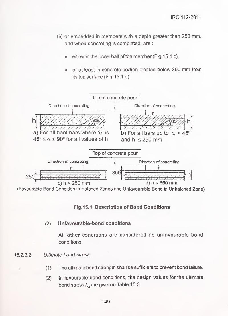
IRC:112-2011
(li) or embedded in members with a depth greater than 250 mm,
and when concreting is completed, are :
• either in the lower half of the member (Fig. 15.1c),
• or at least in concrete portion located below 300 mm from
its top surface (Fig. 1 5.1 .d).
Top of concrete pour
h
Direction of concreting
' .-•'>'>'' ..>>' ..•'.•> >••'>>'y'V
.
y//////7////////A .
'/A///////////////////////
Direction of concreting
/ / / . / / / / ..- / ./ ..
h^//////.//////
y .• y ^ .••///////a) For all bent bars where 'a' is b) For all bars up to a < 45°
45° < a < 90° for ail values of h and h < 250 mm
Top of concrete pour
250
Direction of concreting
L_y 77'7""7'7"y7 / / ^' / / / ^ / j j ..J
300
Direction of concreting
_1' «' y .1' „»•' j' j' ' y
." .' .' . .' .' .' ."
- -
c) h < 250 mm d) h < 550 mm(Favourable Bond Condition in Hatched Zones and Unfavourable Bond In Unhatched Zone)
Fig.1 5.1 Description of Bond Conditions
(2) Unfavourable-bond conditions
All other conditions are considered as unfavourable bond
conditions.
15.2.3.2 Ultimate bond stress
(1 ) The ultimate bond strength shall be sufficient to prevent bond failure.
(2) In favourable bond conditions, the design values for the ultimate
bond stress are given in Table 15.3
149
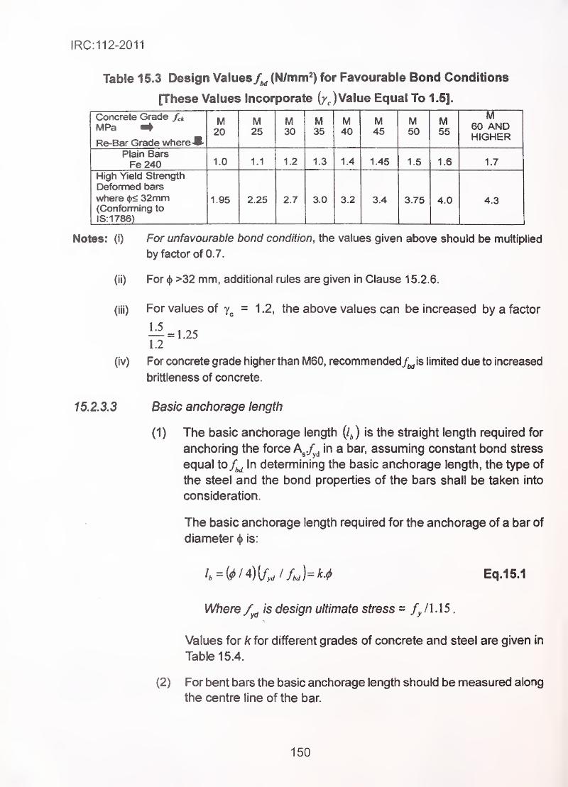
IRC:112-2011
Table 15.3 Design Values/^ (N/mm^) for Favourable Bond Conditions
[These Values Incorporate (/JValue Equal To 1.5].
Concrete Grade fck
MPa ^Re-Bar Grade where^K-
M20
M25
M30
M35
M40
M45
M50
M55
MIV!60 ANDHIGHER
Plain BarsFe240 1.0 1.1 1.2 1.3 1.4 1.45 1.5 1.6 1.7
High Yield Strength
Deformed t^ars
where 32mm(Conforming to
IS: 1786)
1.95 2.25 2.7 3.0 3.2 3.4 3.75 4.0 4.3
Notes: (i) For unfavourable bond condition, the values given above should be multiplied
by factor of 0.7.
(li) For <|> >32 mm, additional rules are given in Clause 15.2.6.
For values of = 1.2, the above values can be increased by a factor
1:^ = 1.251.2
For concrete grade higher than M60, recommendedf^\s limited due to increased
brittleness of concrete.
(iv)
15.2.3.3 Basic anchorage length
(1) The basic anchorage length {/J is the straight length required for
anchoring the force A^.f^^ in a bar, assuming constant bond stress
equal to^ In determining the basic anchorage length, the type of
the steel and the bond properties of the bars shall be taken into
consideration.
The basic anchorage length required for the anchorage of a bar of
diameter (j) is:
4=((^/4)U^//,J=M Eq.15.1
Where is design ultimate stress = / 1 . 1 5
.
Values for k for different grades of concrete and steel are given in
Table 15.4.
(2) For bent bars the basic anchorage length should be measured along
the centre line of the bar.
150
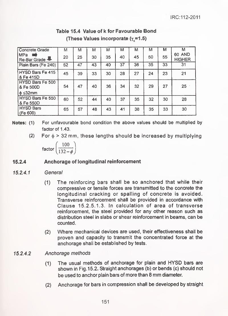
1RC:112-2011
Table 15.4 Value of k for Favourable Bond
(These Values incorporate (y,.=1.5)
Concrete Grade M M M M M M M M ivf
MPa w4Re-Bar Grade
20 25 30 35 40 45 50 5560 ANDHIGHER
Plain Bars (Fe 240) 52 47 43 40 37 36 35 33 31
HYSD Bars Fe415&Fe 41 5D
45 39 33 30 28 27 24 23 21
HYSD Bars Fe 500
& Fe 500D 54 47 40 36 34 32 29 27 25
0 ^32mmHYSD Bars Fe 550& Fe 550D
60 52 44 40 37 35 32 30 28
HYSD Bars
(Fe 600)65 57 48 43 41 38 35 33 30
Notes: (1)
(2)
15.2.4
16.2.4.1
15.2.4.2
For unfavourable bond condition the above values should be multiplied by
factor of 1 .43.
For ^ > 32 mm, these lengths should be increased by multiplying
factor
^ 100^
Anchorage of longitudinal reinforcement
General
(1) The reinforcing bars shall be so anchored that while their
confipressive or tensile forces are transmitted to the concrete the
longitudinal cracking or spalling of concrete is avoided.
Transverse reinforcement shall be provided in accordance with
Clause 15.2.5.1 .3. In calculation of area of transverse
reinforcement, the steel provided for any other reason such as
distribution steel in slabs or shear reinforcement in beams, can be
counted.
(2) Where mechanical devices are used, their effectiveness shall be
proven and capacity to transmit the concentrated force at the
anchorage shall be established by tests.
Anchorage methods
(1) The usual methods of anchorage for plain and HYSD bars are
shown in Fig. 15.2. Straight anchorages (b) or bends (c) should not
be used to anchor plain bars of more than 8 mm diameter.
(2) Anchorage for bars in compression shall be developed by straight
151
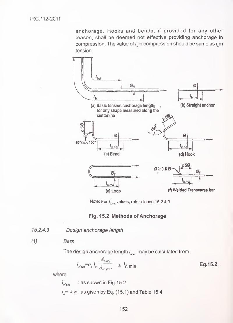
IRC:112-2011
anchorage. Hooks and bends, if provided for any other
reason, shall be deemed not effective providing anchorage in
compression. The value of /Jn compression should be same as ijn
tension.
0 0
(a) Basic tension anchorage lengtlb ,
for any shape measured along the
centerlino
(b) Straight anchor
Ai
090-5 a < 150"
(c) Bend
0
(d) Hook
>50
0
(e)Loop (f) Welded Transvarse bar
Note: For Z^^^, values, refer clause 15.2.4.3
Fig. 15.2 Methods of Anchorage
15.2.4.3 Design anchorage length
(1) Bars
The design anchorage length/^.^^^,
may be calculated from
:
where
/^.^, : as shown in Fig. 15. 2.
1= k.^ :as given by Eq. (15.1) and Table 1 5.4
Eq.15.2
152
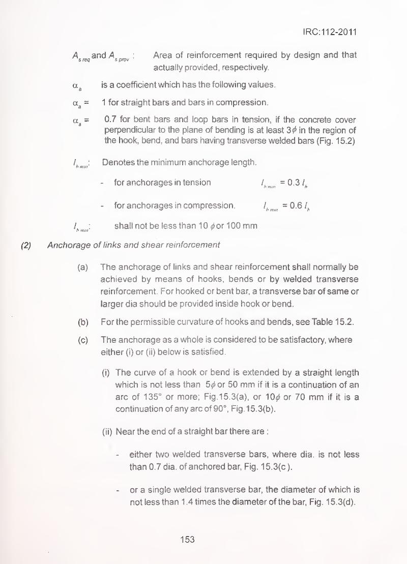
IRC:112-2011
A and A : Area of reinforcement required by design and that
actually provided, respectively.
a 3 is a coefficient which has the following values.
= 1 for straight bars and bars in compression.
= 0.7 for bent bars and loop bars in tension, if the concrete cover
perpendicular to the plane of bending is at least 3^ in the region of
the hook, bend, and bars having transverse welded bars (Fig. 15.2)
l^^^^j. Denotes the m.inimum anchorage length.
- for anchorages in tension /, = 0.3 A^ n III III h
- for anchorages in compression./^^^^^^^
= 0.6
L : shall not be less than 10 ^or 100 mm '
h mill ''
Anchorage of links and shear reinforcement
(a) The anchorage of links and shear reinforcement shall normally be
achieved by means of hooks, bends or by welded transverse
. reinforcement For hooked or bent bar, a transverse bar of same or
larger dia should be provided inside hook or bend.
(b) For the permissible curvature of hooks and bends, see Table 1 5.2.
(c) The anchorage as a whole is considered to be satisfactory, where
either (i) or (ii) below is satisfied.
(i) The curve of a hook or bend is extended by a straight length
which is not less than 5^ or 50 mm if it is a continuation of an
arc of 135° or more; Fig. 15. 3(a), or 10^ or 70 mm if it is a
continuation of any arc of 90"*, Fig. 15.3(b).
(ii) Near the end of a straight bar there are
:
- either two welded transverse bars, where dia. is not less
than 0.7 dia. of anchored bar, Fig. 1 5.3(c ).
- or a single welded transverse bar, the diameter of which is
not less than 1 .4 times the diameter of the bar, Fig. 1 5.3(d).
153
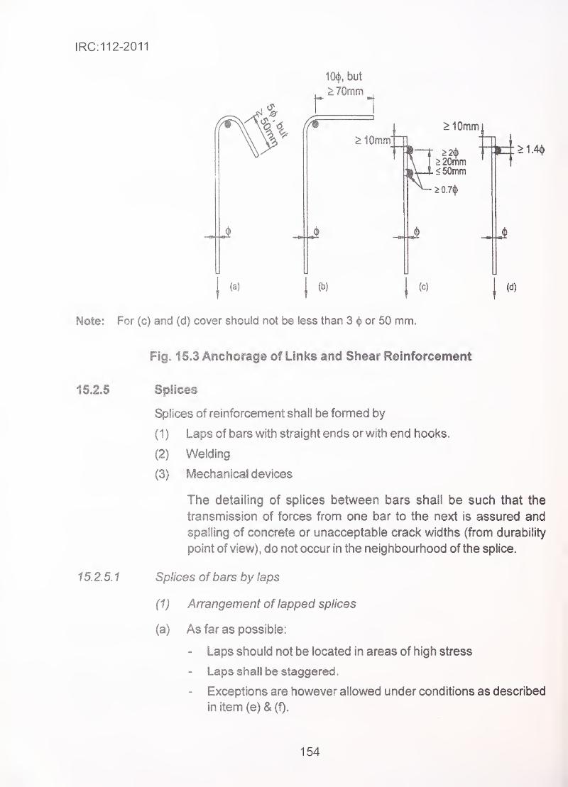
IRC:112-2011
(a)
^% but
>70mm
r 1
(b)
> 10mm"
>10mm
(c)
Note: For (c) and (d) cover should not be less than 3 or 50 mm.
2^ ^4^1.4*0mm t
15.2.5
15.2.5.1
Fi§. 15.3 Anchorage of Links and Shear Reinforcement
Splices
Splices of reinforcement shall be formed by
(1) Laps of bars with straight ends or v/ith end hooks.
(2) Welding
(3) Mechanical devices
The detailing of splices between bars shall be such that the
transmission of forces from one bar to the next is assured and
spalling of concrete or unacceptable crack widths (from durability
point of view), do not occur in the neighbourhood of the splice.
Splices of bars by laps '
^
(1) Arrangement of lapped splices
(a) As far as possible:
- Laps should not be located in areas of high stress
- Laps shall be staggered.
- Exceptions are however allowed under conditions as described
in item(e)&(f).
154
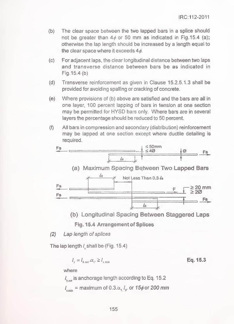
IRC:112-2011
(b) The clear space between the two lapped bars in a splice should
not be greater than A<j> or 50 mm as indicated in Fig. 15.4 (a);
otherwise the lap length should be increased by a length equal to
the clear space where it exceeds 4^.
(c) For adjacent laps, the clear longitudinal distance between two laps
and transverse distance between bars be as indicated in
Fig. 15.4(b)
(d) Transverse reinforcement as given in Clause 15.2.5.1.3 shall be
provided for avoiding spatling or cracking of concrete.
(e) Where provisions of (b) above are satisfied and the bars are all in
one layer, 1 00 percent lapping of bars in tension at one section
may be permitted for HYSD bars only. Where bars are in several
layers the percentage should be reduced to 50 percent.
(!) All bars in compression and secondary (distribution) reinforcement
may be lapped at one section except where ductile detailing is
required.
Fs\
. ^SOmm1^40
\0
-4 '
Fs
(a) Maximum Spacing Between Two Lapped Bars
4
Fs
# Not Than 0.3 4
r ^20 mm
. Fs
(b) Longitudinal Spacing Between Staggered Laps
Fig. 15.4 Arrangement of Splices
(2) Lap length of splices
The lap length shall be (Fig. 1 5.4)
/. ^ is anchorage length according to Eq. 1 5.2
/ .= maximum of 0.3.a^ or t5^ or 200 mm
Eq.15.3
155
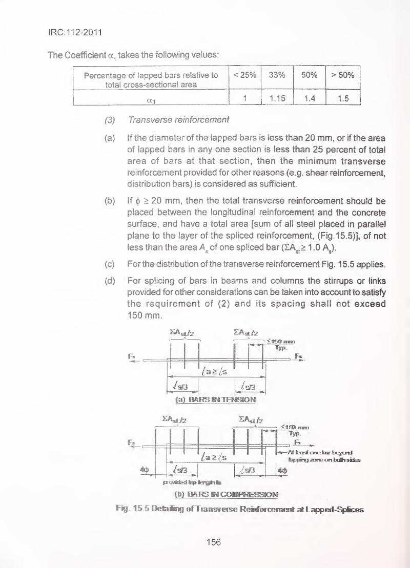
IRC:112-2011
The Coefficient takes the following values:
Percentage of lapped bars relative to
total cross-sectional area
< 25% 33% 50% > 50%
ai 1 1.15 1.4 1.5
(3) Transverse reinforcement
(a) If the diameter of the lapped bars is less than 20 mm, or if the area
of lapped bars in any one section is less than 25 percent of total
area of bars at that section, then the minimum transverse
reinforcement provided for other reasons (e.g. shear reinforcement,
distribution bars) is considered as sufficient.
(b) if ^ > 20 mm, then the total transverse reinforcement should be
placed between the longitudinal reinforcement and the concrete
surface, and have a total area [sum of all steel placed in parallel
plane to the layer of the spliced reinforcement. (Fig. 15.5)], of not
less than the area of one spliced bar (ZA^,> 1 .0 AJ.
(c) For the distribution of the transverse reinforcement Fig. 1 5.5 applies.
(d) For splicing of bars in beams and columns the stirrups or links
provided for other considerations can be taken into account to satisfy
the requirement of (2) and its spacing shall not exceed
150 mm.
(a) m
^• <1SDi
-jM Isafit one km- beyond
4#
Fig. 15.5 DebBng ofTransverse Heiriiirceinefti M L^iped-S|3ices
156
IRC:112-2011
Splidng by welding ^'
.
Welded joints may be used subject to the following
:
(1) Welding of Fe 240 grade bars conforming to IS 432 shall be
permitted. Welding of other grades of bars shown in Table 15.1 is
generally not recommended except in special cases mentioned in
(8) below.
(2) In special rases the HYSD bars mnforming to IS 1 786 may be welded
after confirming that the equivalent carbon percentage calculated from
the chemical comparisons as given below are within the limitations
of CE mentioned below:
For guaranteed weldability, the Carbon Equivalent, CE using the
fonnula:
_^ ^ Mn Cr + Mo + V Ni + CuL.t. = L +— + -—— +——— shall not be more than 0.53
o 5 I
J
percent, when microalioys/low alloys are used. When rnicroalioys/
low alloys are not used, carbon equivalent using the fonnula:
C£ = C +— shall not be more than 0.42 percent.
6
Reinforcement bars/wires with carbon equivalent above 0.42 percent
should, however be welded with precaution. Use of low hydrogen
basic coated electrodes with matching strength bars/wires is
recommended.
(3) Welding shall conform to IS 2751 and IS 9417 except as provided
herein.
(4) Generally, shop welding in controlled conditions is to be preferred,
where feasible. Site welding where necessary shall, however, be
permitted when the facilities, equipment, process, consumables,
operators, welding procedure are adequate to produce and maintain
uniform quality at par with that attainable in shop welding to the
satisfaction of the engineer. ^
(5) Welding may be carried out by metal arc welding process. Oxy-
acetylene welding shall not be permissible. Any other process maybe used subject to the approval of the engineer and necessary
additional requirements to ensure satisfactory joint performance.
Precautions on over heating, choice of electrode, selection of correct
current in arc welding etc., should be strictly observed.
(6) All bars shall be butt welded except for smaller diameter bars with
diameter of less than 20 mm which may be lap welded. Single-V or
157
IRC:112-2011
Double-V butt joints may generally be used. For vertical bars single
bevel or double bevel butt joints may be used
.
(7) Welded joints shall be located well away from bends and not less
than twice the bar diameter away from a bend
.
(8) Joint welding procedures which are to be employed shall invariably
be established by a procedure specification and shall be qualified
prior to use by tests as prescribed in IS 2751 . All welders and welding
operators to be employed shall have to be qualified by tests
prescribed in IS 2751 . Inspection of welds shall conform to IS 822
and destructive or non-destructive testing may be undertaken whendeemed necessary. Joints with weld defects detected by visual
inspection or dimensional inspection shall not be accepted.
15.2.5.3 Splicing by mechanical devices
(1) Bars may be spliced with mechanical devices, e.g. by special grade
steel sleeves swaged on to the bars in end to end contact or by
threaded couplers. A mechanical splice including its connecting
elements shall develop in tension or compression at least 125 per
cent of the characteristic strength/^
.
(a) For established systems the design shall be based on
manufacturer's test certificate of ultimate strength with
appropriate safety factor to be selected by the designer. In
addition, field testing on selected samples from actual supply
at site shall be carried out, both for acceptance and as quality
control tool.
(b) For new systems acceptance testing shall be carried out in
laboratories, in addition, field testing on selected samples from
actual supply at site shall be carried out, both for acceptance
and as quality control tool.
(2) At location of mechanical splices reduction in minimum cover may
be accepted but should not be less than 30 mm.
1 5.2.6 Additional rules for high yield steel deformed (HYSD) bars exceeding
32 mm in diameter
15.2.6.1 General
(1) The rules given below are complementary to those given in
Clause 15.2.3.
158
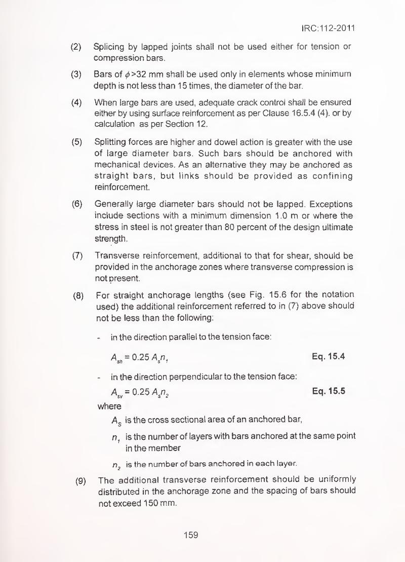
IRC:112-2011
(2) Splicing by lapped joints shall not be used either for tension or
compression bars.
(3) Bars of ^>32 mm shall be used only In elements whose minimum
depth is not less than 1 5 times, the diameter of the bar.
(4) When large bars are used, adequate crack control shall be ensured
either by using surface reinforcement as per Clause 16.5.4 (4). or by
calculation as per Section 12.
(5) Splitting forces are higher and dowel action is greater with the use
of large diameter bars. Such bars should be anchored with
mechanical devices. As an alternative they may be anchored as
straight bars, but links should be provided as confining
reinforcement.
(6) Generally large diameter bars should not be lapped. Exceptions
include sections with a minimum dimension 1.0 m or where the
stress in steel is not greater than 80 percent of the design ultimate
strength.
(7) Transverse reinforcement, additional to that for shear, should be
provided in the anchorage zones where transverse compression is
not present.
(8) For straight anchorage lengths (see Fig. 15.6 for the notation
used) the additional reinforcement referred to In (7) above should
not be less than the following:
- in the direction parallel to the tension face:
= 0.25 A^n, Eq.1S.4
- in the direction perpendicular to the tension face:
A^^^026A^r}^ Eq. 15.5
where
A^ is the cross sectional area of an anchored bar,
is the number of layers with bars anchored at the same point
in the member
n, is the number of bars anchored in each layer.«
(9) The additional transverse reinforcement should be uniformly
distributed in the anchorage zone and the spacing of bars should
not exceed 150 mm.
159
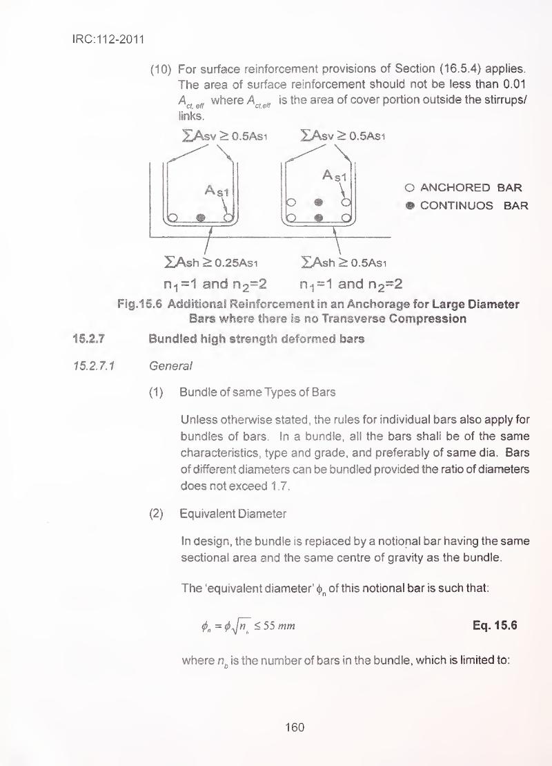
IRC:112-2011
(10) For surface reinforcement provisions of Section (16.5.4) applies.
The area of surface reinforcement should not be less than 0.01
where A^^^^ is the area of cover portion outside the stirrups/
links.
2Asv > 0.5AS1 XAsv > 0,5Asi
\Asl
Asi
oO ANCHORED BAR
• CONTINUOS BAR
5LAsh > 0.25AS1 XAsh > O.SAsi
0^=1 and 02=2 n.^=1 and n2=2
Fig.15.6 Additional Reinforcement in an Anchorage for Large Diameter
Bars where there is no Transverse Compression
15.2.7 Bundled high strength deformed bars
15.2.7.1 General
(1) Bundle of same Types of Bars
Unless othenwise stated, the rules for individual bars also apply for
bundles of bars. In a bundle, all the bars shall be of the same
characteristics, type and grade, and preferably of same dia. Bars
of different diameters can be bundled provided the ratio of diameters
does not exceed 1.7._
-
(2) Equivalent Diameter ,- - '
'
In design, the bundle is replaced by a notional bar having the same
sectional area and the same centre of gravity as the bundle.
The 'equivalent diameter' (j)^ of this notional bar is such that:
<l>„^(l>^^<55mm Eq.15.6
where is the number of bars in the bundle, which is limited to:
160
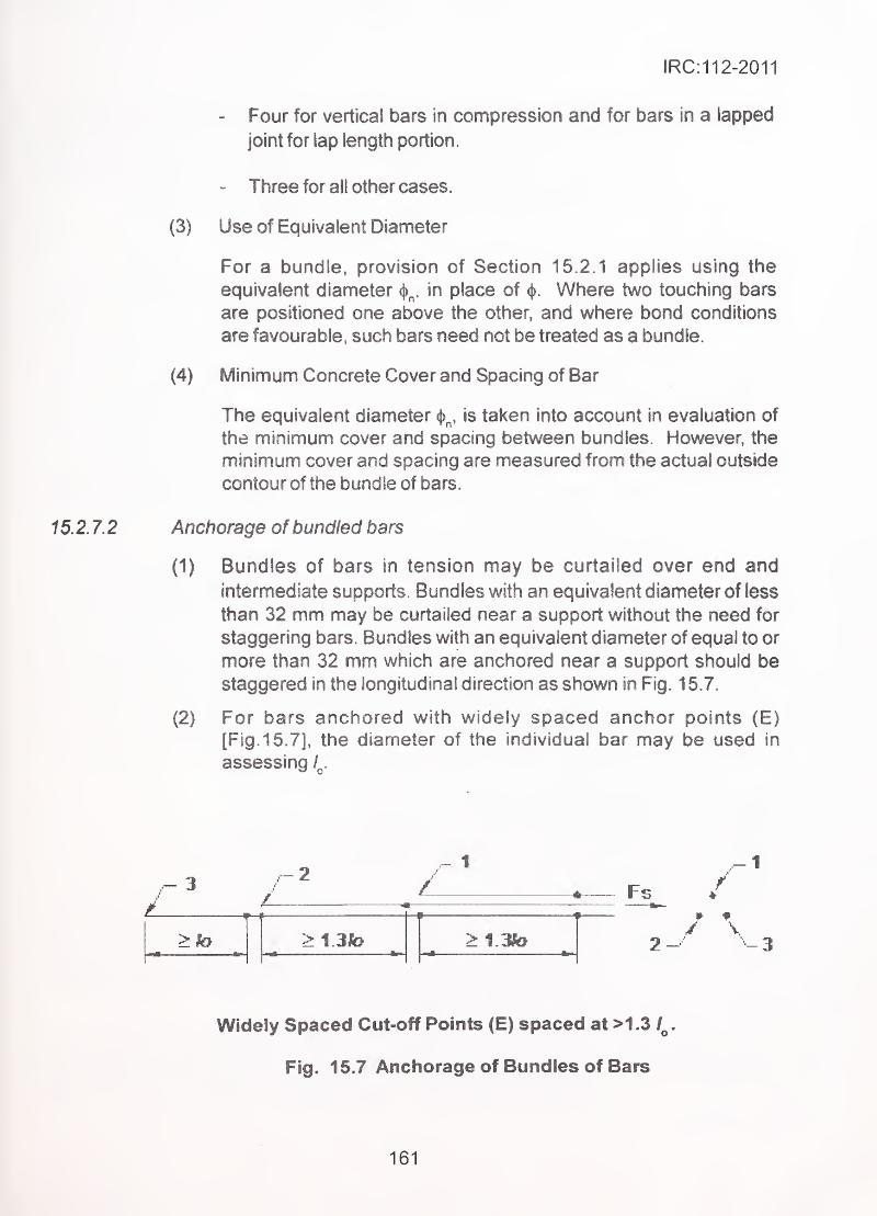
IRC:112-2011
- .- Four for vertical bars in compression and for bars in a lapped
joint for lap length portion
.
- Three for all other cases.
(3) Use of Equivalent Diameter
For a bundle, provision of Section 15.2.1 applies using the
equivalent diameter in place of <j). Where two touching bars
are positioned one above the other, and where bond conditions
are favourable, such bars need not be treated as a bundle.
(4) Minimum Concrete Cover and Spacing of Bar
The equivalent diameter sj>^, is taken into account in evaluation of
the minimum cover and spacing between bundles. However, the
' minimum cover and spacing are measured from the actual outside
^
-
. contour of the bundle of bars
15.2. 7.2 Anchorage of bundled bars '•
, (1) Bundles of bars in tension may be curtailed over end and
intermediate supports. Bundles with an equivalent diameter of less
than 32 mm may be curtailed near a support without the need for
staggering bars. Bundles with an equivalent diameter of equal to or
more than 32 mm which are anchored near a support should be
staggered in the longitudinal direction as shown in Fig. 1 5.7.
'
. (2) For bars anchored with widely spaced anchor points (E)
[Fig. 15. 7], the diameter of the individual bar may be used in
assessing /
..- 3 Fs(
1—
1
p i t
> to___ fc^
> 1 3to > 1 3to/ V
2--' -3
Widely Spaced Cut-off Points (E) spaced at >1 .3 .
Fig. 15.7 Anchorage of Bundles of Bars
161
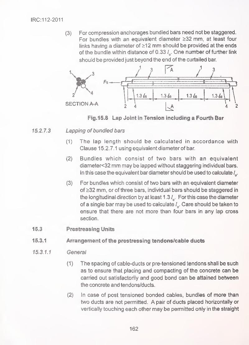
IRC:112-2011
(3) For compression anchorages bundled bars need not be staggered.
For bundles with an equivalent diameter >32 mm, at least four
links having a diameter of >12 mm should be provided at the ends
of the bundle within distance of 0.33 One number of further link
should be provided just beyond the end of the curtailed bar.
Fig.1S.8 Lap Joint in Tension including a Fourth Bar
1 5. 2. 7.3 Lapping of bundled bars
(1) The lap length should be calculated in accordance with
Clause 15.2.7.1 using equivalent diameter of bar.
(2) Bundles which consist of two bars with an equivalent
diameter<32 mm may be lapped without staggering iodividual bars,
in this case the equivalent bar diameter should be used to calculate Z^.
(3) For bundles which consist of two bars with an equivalent diameter
of >32 mm, or of three bars, individual bars should be staggered in
the longitudinal direction by at least 1 .3 1^. For this case the diameter
of a single bar may be used to calculate l^. Care should be taken to
ensure that there are not more than four bars in any lap cross
section.
15.3 Prestressing Units
15,3.1 Arrangement of the prestressing tendons/cable ducts
15.3.1.1 General
(1 ) The spacing of cable-ducts or pre-tensioned tendons shall be such
as to ensure that placing and compacting of the concrete can be
carried out satisfactorily and good bond can be attained between
the concrete and tendons/ducts.
(2) In case of post tensioned bonded cables, bundles of more than
two ducts are not permitted. A pair of ducts placed horizontally or
vertically touching each other may be permitted only in the straight
162
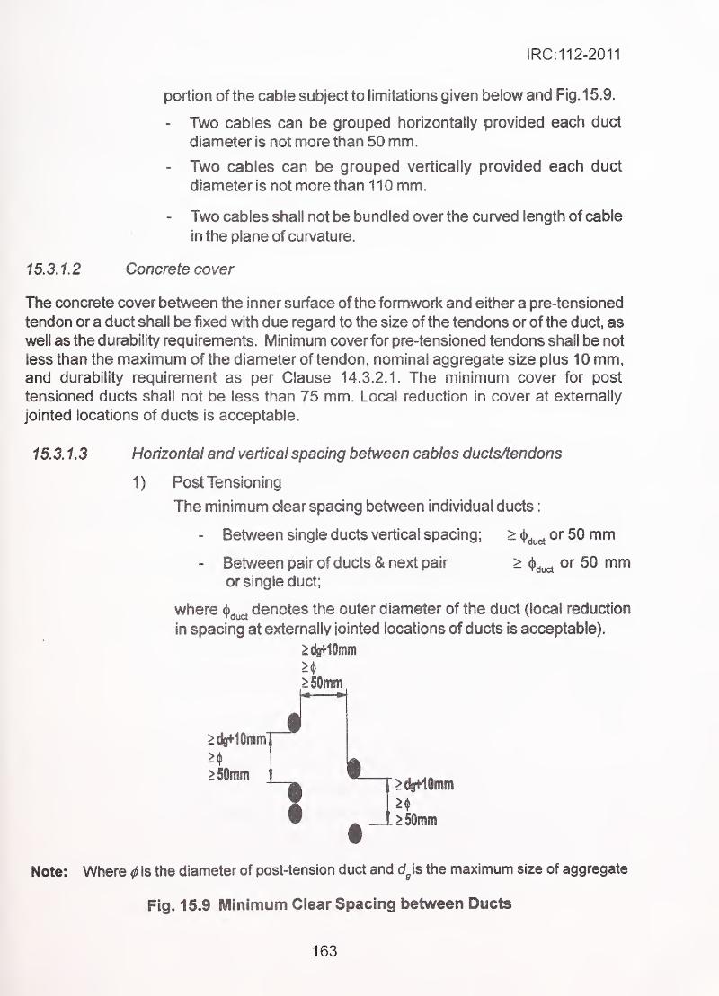
IRC:112-2011
portion of the cable subject to limitations given below and Fig. 1 5.9.
- Two cables can be grouped horizontally provided each duct
diameter is not more than 50 mm.
- Two cables can be grouped vertically provided each duct
diameter is not more than 110 mm.
- Two cables shall not be bundled over the curved length of cable
in the plane of curvature.
15.3.1.2 Concrete cover
The concrete cover between the inner surface of the formwork and either a pre-tensioned
tendon or a duct shall be fixed with due regard to the size of the tendons or of the duct, as
well as the durability requirements. Minimum cover for pre-tensioned tendons shall be not
less than the maximum of the diameter of tendon, nominal aggregate size plus 10 mm,and durability requirement as per Clause 14.3.2.1. The minimum cover for post
tensioned ducts shall not be less than 75 mm. Local reduction in cover at externally
jointed locations of ducts is acceptable.
15.3.1.3 Horizontal and vertical spacing between cables ductsAendons
1) Post Tensioning
The minimum clear spacing between individual ducts
:
- Between single ducts vertical spacing; > or 50 mm
Between pair of ducts & next pair > ^^^^ or 50 mmor single duct;
where denotes the outer diameter of the duct (local reduction
in spacing at externally iointed locations of ducts is acceptable).
>50mm
1>#10mm
. ^ SOmin
Note: Where ^ is the diameter of post-tension duct and Is the maximum size of aggregate
Fig. 15.9 Minimum Clear Spacing between Ducts
163
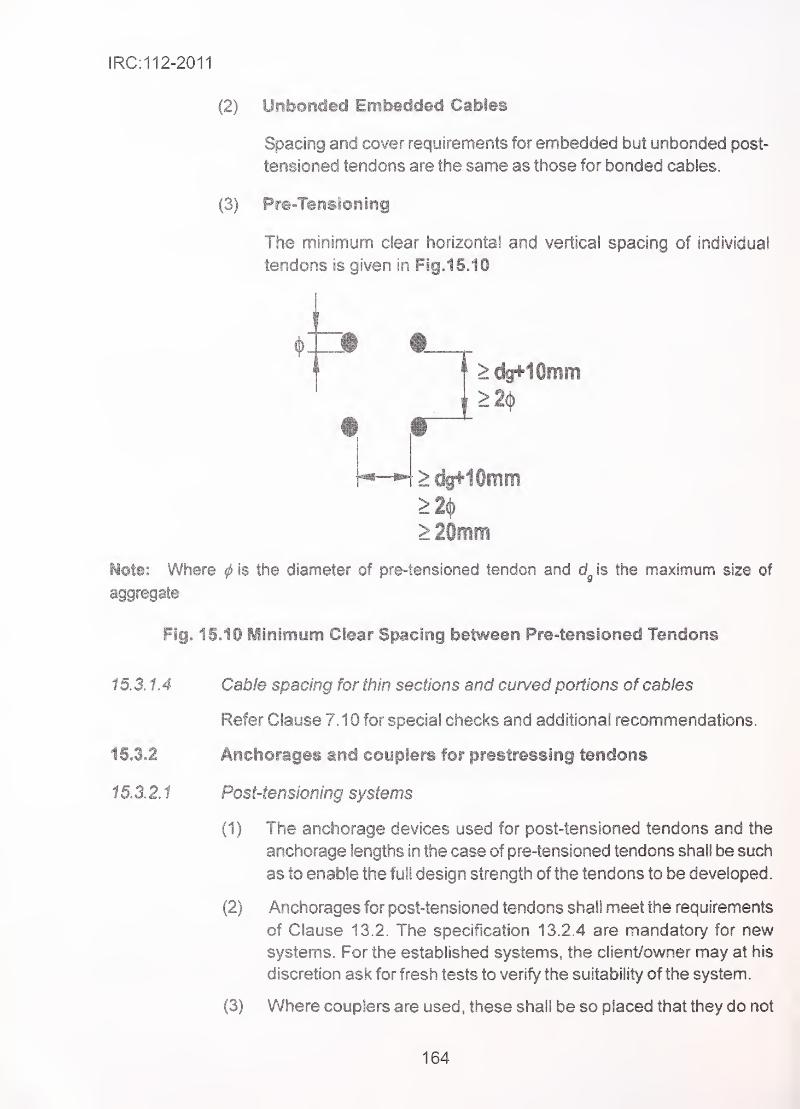
IRC:112-2011
(2) Unbonded Eifibeddeci Cables .. .
.
Spacing and cover requirements for embedded but unbonded post-
tensioned tendons are the same as those for bonded cables.
(3) Pre-Tensioning
The minimum clear horizontal and vertical spacing of individual
tendons is given in FigJ5.10
>%HOmin>2ij)
>dfffr10iiim
>20mm
Note: Where ^ is the diameter of pre-tensioned tendon and is the maximum size of
aggregate
Fig. 15.10 Minimum Cfear Spacing between Pre-tensioned Tendons
15.3.1.4 Cable spacing for thin sections and curved portions of cables
Refer Clause 7.10 for special checks and additional recommendations.
15.3.2 Anchorages and coupSers for prestressing tendons
15.3.2.1 Post'tensioning systems '.
(1) The anchorage devices used for post-tensioned tendons and the
anchorage lengths in the case of pre-tensioned tendons shall be such
as to enable the full design strength of the tendons to be developed.
(2) Anchorages for post-tensioned tendons shall meet the requirements
of Clause 13.2. The specification 13.2.4 are mandatory for new
systems. For the established systems, the client/owner may at his
discretion ask for fresh tests to verify the suitability of the system.
(3) Where couplers are used , these shall be so placed that they do not
164
IRC:112-2011
adversely affect the load carrying capacity of the member and that
any temporary anchorage which may be needed during construction
can be introduced in a satisfactory manner. The requirements of
minimum concrete cover over couplers and reinforcement for bursting
and spaliing shall be as per the specifications of manufacturers and
should be subjected to acceptance tests similar to those covered in
13 2.4 for anchorages.
(4) In general, couplers should be located away from intermediate
supports.
(5) The use of couplers for more than on 50 percent of the tendons at any
cross-section should be avoided.
The distance between any two successive sections at which cables
are coupled should not be closer than 1.5 m. for structural memberswhere depth is less than 2.0 m and not closer than 3.0 m. for members
of depth greater than 2 .0 m.
(6) _If tendons are anchored at a construction joint or within a concrete
' member (whether on an external rib, within a pocket or entirely inside
' the member), it should be checked that a minimum residual
compressive stress of at least 3 MPa is present in the direction of the
anchored prestressing force, under the frequent load combination. If
the minimum residual stress is not present, reinforcement should be
provided to cater for the local tension beyond terminated tendon near
the anchor. The check for residual stress is not required If the tendon
is coupled at the anchorage considered.
(7) Anchorage of tendons in top surface of deck shall not be permitted.
(8) For tendons anchored in the deck slab and soffit slab, local thickening
or blisters shall be so provided that minimum cover to anchorage
shall not be less than 200 mm.
Pre-tensioning systems
(1 ) Anchorage of pre-tensioned tendons
In anchorage regions for pre-tensioned tendons, the following length
parameters should be considered, Refer Fig. 15. 11.
(a) Transmission length over which the prestressing force (PJ is
fully transmitted to the concrete.
165
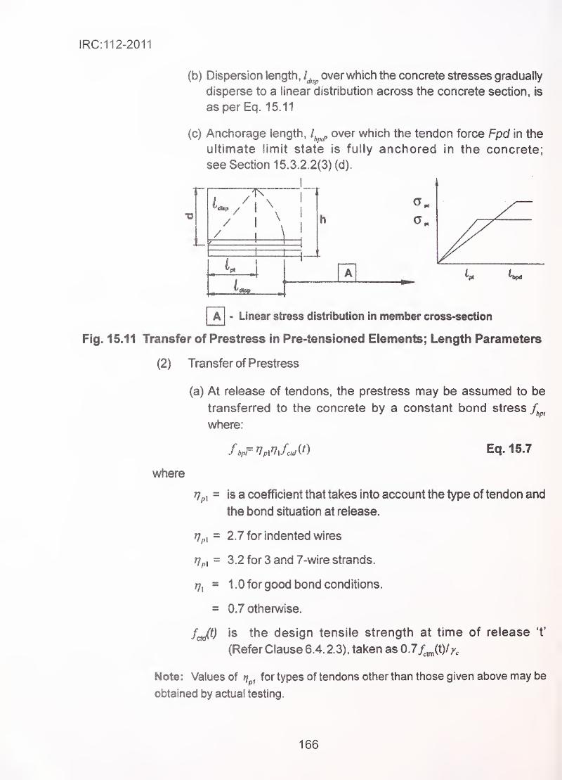
IRC:112-2011
(b) Dispersion length, /^^^ overwhich the concrete stresses gradually
disperse to a linear distribution across the concrete section, is
as per Eq. 16.11
(c) Anchorage length, over which the tendon force Fpd in the
ultimate limit state is fully anchored in the concrete;
see Section 15.3.2.2(3) (d).
//
1 \
/ \
/
[~a] - Linear stress distribution in member cross-section
Fig, 15.11 Transfer of Prestress in Pre-tensioned Elements: Length Parameters
(2) Transfer of Prestress
(a) At release of tendons, the prestress may be assumed to be
transferred to the concrete by a constant bond stress/^^,
where:
fbpr^pinJaAO Eq.15.7
where
is a coefficient that takes into account the type of tendon and
the bond situation at release.
2.7 for indented wires
3.2 for 3 and 7-wire strands.
1 .0 for good bond conditions.
0.7 otherwise. '
^
fcJ^) is the design tensile strength at time of release 't'
(Refer Clause 6.4. 2.3). taken as 0.7/^Jt)//,
Note: Values of rf^^ for types of tendons other than those given above may be
obtained by actual testing.
166
IRC:112-2011
(b) The basic value of the transmission length, l^,- is given by:
V- 7. Eq.lSJ
Jbpt
where
a, = 1 .0 for gradual release
= 1 .25 for sudden release
^2 ~ 0.25 for tendons with circular cross section
= 0. 1 9 for 3 and 7-wire strands
^ = is the nominal diameter of tendon
^pmQ - is the tendon stress just after release
(c) The design value of the transmission length should be taken
depending on the design situation, given in Eq. 15.9 or 15.10.
I,, = 0.81^^ Eq.15.9
OR
I,,, = 1.21^, Eq.1S.10
Note :The lower value is used for verification of local stresses at
release, the higher value for ultimate limit states (shear, anchorage
etc).
(d) Concrete stresses may be assumed to have a linear distribution
outside the dispersion length.
(Refer Fig. 15.11) Eq. 15.11
(e) Alternative build-up of prestress may be assumed, if adequately
justified and if the transmission length is modified accordingly.
Anchorage of Tensile Force for the Ultimate Limit State
(a) The anchorage of tendons should be checked in sections where
the concrete tensile stress exceeds f^oos- The tendon forces
should be calculated for a cracked section, including the effect of
167
shear accx5rdlng to Section 103.3.3(6). Where the concrete tensile
stress is less than f^^^g no anchorage check is necessary.
(b) The bond strength for anchorage in the ultimate limit state is:
fhpd = np2n\fcui Eq. 15.12
where
rjj,. is a coefficient that takes into account the type of
. tendon and the bond situation at anchorage
= 1 4 for indented wires or
= 1.2 for 7-wire strands
r}\ is as defined in Eq. 1 5.7.
(c) Due to increasing brittleness with higher concrete strength, f^^^^^
should here be limited to the value for M75.
(d) The total anchorage length for anchoring a tendon with stress
C =^pt2 +«2^Kc^- ^pnry^tp, Eq. 15.13
where
!pt2 is the upper design value of transmission length = 1.2 /
as defined in Clause 1 5.3.2.2 (2)
cTp^ is the tendon stress corresponding to the force described
in (a)
Qp^ ^ is the prestress after all losses
(e) Tendon stresses in the anchorage zone are illustrated in
Fig. 15.12.
(f) In case of combination of ordinary and pre-tensioned
reinforcement, within the same zone of concrete the anchorage
capacities of each may be separately calculated and added for
design varification.
168
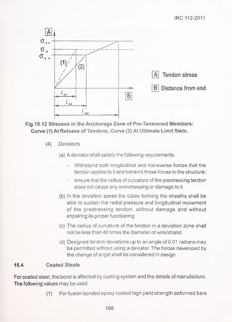
IRC:112-2011
a0
/
(2)
Tendon strsss
[b] Distance from end
B
Fig. 15. 12 Stresses in the Anchorage Zone of Pre-Tensioned Members:
Curve (1) At Release of Tendons, Curve (2) At Ultimate Limit State.
(4) Deviators
(a) A deviator shall satisfy the following requirements:
- Withstand both longitudinal and transverse forces that the
tendon applies to it and transmit these forces to the structure;
- ensure that the radius of curvature of the prestressing tendon
does not cause any overstressing or damage to it.
(b) in the deviation zones the tubes forming the sheaths shall be
able to sustain the radial pressure and longitudinal movement
of the prestressing tendon, without damage and without
impairing its proper functioning.
(c) The radius of curvature of the tendon in a deviation zone shall
not be less than 40 times the diameter of wire/strand
.
(d) Designed tendon deviations up to an angle of 0.01 radians maybe permitted without using a deviator. The forces developed by
the change of angle shall be considered In design.
For coated steel, the bond is affected by coating system and the details of manufacture.
The following values may be used:
(1 ) For fusion bonded epoxy coated high yield strength deformed bars
15.4 Coated Steels
169

(HYSD) and prestresssing tendons, bond values given in previous
Sections shall be reduced by 20 percent, and anchorage and lap
lengths increased by 25 percent.
The factor of 0.7 for reduction of above modified lap length to
account for hooks and bends, shall remain unchanged.
For galvanised and stainless steel, the bond is to be taken the sameas for non-galvanised steel.
170
IRC:112-2011
SECTION 16 DETAILIiMG REQUIREfVIENTS OFSTRUCTURAL MEMBERS
General
(1) Detailing requirements given below are in addition to those given
in Section 15.
(2) Minimum areas of reinforcement are given in order to prevent a
brittle failure, wide cracks and also to resist forces arising from
restrained actions.
(3) In addition to the detailing of reinforcement and prestressing steel,
the dimensional restrictions on various types of elements are also
covered.
Columns of Solid Section.
Sectional dimensions
(1) These Clauses deal with columns of any cross-sectiona! shape for
which the larger dimension of solid concrete section is not greater
than 4 times the smaller dimension of the concrete section.
(2) For purpose of this Section, columns are classified in two types
(i) Pedestal columns and (ii) Other columns.
Pedestal columns are defined as those columns for which
length/least radius of gyration is less than 12.
Longitudinal reinforcement
(1) Longitudinal reinforcement for pedestal columns shall not be less
than 0.15 percent of cross-sectional area of concrete.
(2) For other columns, bar diameter shall not be less than 1 2 mm and
spacing measured along periphery of column, not more than
200 mm.
(3) For other columns, the minimum cross-sectional area of total
longitudinal reinforcement min. should be derived from the
following condition:
= ^'^^^'-^^or 0.002 Aj, which ever is greater
fyd
171
IRC:112-2011
where
is the design yield strength of the reinforcement,
Nj,^ is the design axial compression force.
is the gross cross-sectional area of concrete.
(4) The maximum cross-sectional area of reinforcement, outside lap
portion shall not be more than 0.04 A^. At lap section, it shall not
be greater than 0.08 A^.
(5) The longitudinal bars should be distributed around the periphery of
the section. For columns of circular cross-section the minimumnumber of bars is six. For columns having a regular polygonal cross
section or having two adjacent surfaces meeting at any angle, at
least one bar shall be placed near the junction of the two surfaces.
16.2.3 Transverse reinforcement
Concrete columns shall have transverse reinforcement to hold the longitudinal reinforcement
in place and avoid its buckling. The transverse reinforcement shall be in the form of lateral
*tes (polygonal links), circular rings , helix and open ties, used singly or in combination as
required.
(1) Helical reinforcement intended for making use of increased load
capacity by confinement of concrete, shall satisfy requirements in
(i) & (ii) in addition to other requirements given in (2) to (9).
(i) The end of helical reinforcement consisting ofevenly spaced helical
turns shall be properly anchored. The splicing of the helical
turns shall be made by welding or by a lap of one and a half
• turns.
(ii) The pitch of the helical turns shall not be more than 75 mm nor
more than one sixth the diameter of the core of the column.
(2) The diameter of the transverse reinforcement shall not be less than
8 mm or one quarter of the maximum diameter of the longitudinal
bar, whichever is greater.
(3) The transverse reinforcement shall be adequately anchored.
(4) The spacing of the transverse reinforcement along the column axis
shall not exceed the lesser of the following
:
- 1 2 times the minim.um diameter of the longitudinal bars.
172
IRC:112-2011
- the leastdiinension of the column,
- 200 mm
(5) At location of laps, the transverse reinforcement shall satisfy
requirements of Clause 15.2.5.1,(3)
(6) Where the direction of the longitudinal bar changes (e.g. at changes
in column size), the spacing of transverse reinforcement should be
calculated, taking account of the lateral forces involved. These
effects may be ignored if the change of direction is less than or
equal to 1 in 12.
(7) At the location of change in dimension of concrete section
(e.g. flaring of section) transverse reinforcement should be provided
to balance internal transverse tensile stresses in concrete.
(8) Every longitudinal bar (or group of longitudinal bars) placed at a
corner should be held in two directions by transverse reinforcement.
The included angle between these two directions should not be
more than 1 35 degrees.
(9) A maximum of 3 bars on one face and not more than 5 bars on two
faces meeting at each corner including the corner bar, can be
secured against buckling by any one set of transverse
reinforcement. The distance of the farthest bar thus supported
from the corner of column shall not be more than 1 50 mm.
(1 0) No bar within a compression zone should be further than 1 50 mmfrom a restrained bar.
R.C. Walls and Wall Type Piers
(1 ) These clauses deal with reinforced concrete walls of which the larger
dimension measured horizontally is more than four times the smaller
dimension.
(2) The amount and proper detailing of reinforcement may be derived
from FEM analysis or strut-and-tie model within the dispersal zone
of concentrated loads. For walls subjected to predominantly out of
plane bending, the rules of slab apply if they are more severe.
Vertical reinforcement
(1 ) The diameter of bar should not be less than 1 2 mm.
(2) The total area of the vertical reinforcement should be between
0.0024 and 0.04 vA^outside the locations of taps of vertical steel.C V
173
IRC:112-2011
(3) This reinforcement should be provided at two faces taking into
account the direct axiai force and biaxial bending, but shall not beless than 0.0012 >A^on either face.
(4) The distance between two adjacent vertical bars shall not exceed200 mm.
16.3.2 Horizontal reinforcement
(1) Horizontal reinforcement running parallel to the faces of the wall
should be provided and arranged at each surface between the
vertical reinforcement and the nearest surface. The area of total
horizontal reinforcement should not be less than 25 percent of the
area of total vertical reinforcement or 0.001 whichever is greater.
(2) The spacing between two adjacent horizontal bars shall not be morethan 300 mm.
(3) The diameter shall not be less than one quarter of that of the largest
diameter of vertical bars, nor less than 8 mm.
16.3.3 Transverse reinforcement
If the area of the load carrying vertical reinforcement in two faces exceeds 0.02 this
reinforcement should be enclosed by stirrups in accordance with Clause 16.2.3 for columns.
16.4 Hollovy/ Piers/Columns '
•
'
Hollow piers/columns shall satisfy all of the following conditions:
(1) The largest overall dimension is not greater than four times the
smallest overall dimension.
(2) The height is such that the ratio of effective length to radius of
gyration is not less than 1 2.
(3) The two ends are capped by solid structural members of sufficient
thickness to ensure that for unit as a whole, the plane sections
remain plane under action of axial load and bending. A solid
reinforced concrete slab, having thickness not less than 1/3'^
the size of clear inside dimension of the hollow section in the
direction of spanning of the slab and integrally connected to the
walls of the hollow pier/column, may be considered to fulfil the
requirement.
(4) The wall thickness shall not be less than 300 mm.
16.4.1 Detailing rules
(1 ) For wall type pier of non-circular hallow section with length less than
four times the width, the rules for solid columns stipulated in
Clause 16.2 will apply
174
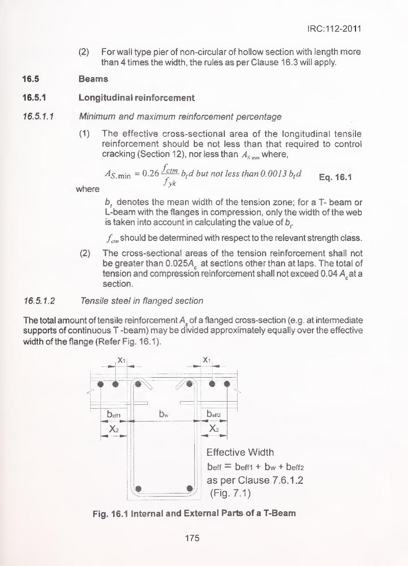
IRC:112-2011
16.5
16.5.1
16,5.1.1
(2) For wall type pier of non-circular of hollow section with length morethan 4 times the width, the rules as per Clause 16.3 will apply.
Beams
Longitudinal reinforcement .
Minimum and maximum reinforcement percentage
(1) The effective cross-sectional area of the longitudinal tensile
reinforcement should be not less than that required to control
cracking (Section 1 2), nor less than where,
where
As min = O.ie^^bfd but not less than 0.0013 bfdfyk
Eq.16.1
(2)
5, denotes the mean width of the tension zone; for a T- beam or
L-beam with the flanges in compression, only the width of the webis taken into account in calculating the value of b^.
f^,„ should be determined with respect to the relevant strength class.
The cross-sectional areas of the tension reinforcement shall not
be greater than 0.025A^ at sections other than at laps. The total of
tension and compression reinforcement shall not exceed 0.04 >A^at a
16.5.1,2
section.
Tensile steel in flanged section
The total amount of tensile reinforcement of a flanged cross-section (e.g. at intemnedlate
supports of continuous T -beam) may be divided approximately equally over the effective
width of the flange (Refer Fig. 16.1).
Xi Xi
beff1 bw Ieft2
Effective Width
beff = beff1 + bw + beff2
as per Clause 7.6.1.2
(Fig. 7,1)
Fig. 16.1 Internal and External Parts of a T-Beam
175
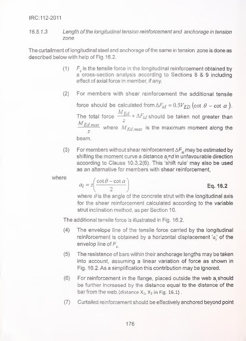
IRC:112-2011
16.5.1.3 Length ofthe longitudinal tension reinforcement and anchorage in tension
zone -.
The curtailment of longitudinal steel and anchorage ofthe same in tension zone is done as
described below with help of Fig. 16.2.
(1 ) is the tensile force in the longitudinal reinforcement obtained by
a cross-section analysis according to Sections 8 & 9 including
effect of axial force in member, if any.
(2) For members with shear reinforcement the additional tensile
force should be calculated from AF^^ = O.SF^^ (cot 0 - cot a).
The total force + should be taken not greater than
—^^-^^where M£j_^^ is the maximum moment along the
z
beam.
(3) For members without shear reinforcement AF^^ may be estimated by
shifting the moment curve a distance a=d in unfavourable direction
according to Clause 10.3.2(6). This 'shift rule' may also be used
as an alternative for members with shear reinforcement,
where
a/ = 2f cot ^ -cot a ^
Eq. 16.2V 2
where ^is the angle of the concrete strut with the longitudinal axis
for the shear reinforcement calculated according to the variable
strut inclination method, as per Section 1 0.
The additional tensile force is illustrated in Fig. 16.2.
(4) The envelope line of the tensile force carried by the longitudinal
reinforcement is obtained by a horizontal displacement of the
envelop line of
(5) The resistance of bars within their anchorage lengths may be taken
into account, assuming a linear variation of force as shown in
Fig. 16.2. As a simplification this contribution may be ignored.
(6) For reinforcement in the flange, placed outside the web a, should
be further increased by the distance equal to the distance of the
bar from the web. (distance Xi, Xz in Fig. 16.1)
.
(7) Curtailed reinforcement should be effectively anchored beyond point
176
IRC:112-2011
where it is no longer required. The anchorage length (la) should
not be less than larger of distance 'd or where 'cf is the
effective depth of member and is calculated as per Eq. 15.2
•' of Section 15.
(8) The diagram of the resisting tensile forces should lie outside the
envelope line of the acting tensile force, displaced as described
above.
(9) The anchorage lengths of bent-up bars which contribute to the,
resistance to shear should be not less than 1.3 4 when anchored
in the tension zone and 0.7 /^^^, when anchored in the compression
zone.
fA] - Envelope of design @ - Tensile force Fm \c\ - Tensile capacity Fr«mquirement Fs^MEo/z+Nm increased by A Fik of reinftvcement
> Fs* AFki
Fig. 1 6.2 Curtailment of longitudinal reinforcement
16.5.1.4 Anchorage ofspan reinforcement at an end support
(1 ) Over supports with little or no end fixity it is necessary to retain not
less than one-quarter of the maximum reinforcement in the span.
(2) The anchorage of the reinforcement should be capable of resisting
a tensile force of:
^s = Ve^.^ + Ne^ Eq.16.3a
Where AT^^ denotes the design axial force taken by the steel, and F^^as
defined in Section 10, and a^ as defined in Clause 16.5.1.3. A^^,^ is
taken as positive if it is tensile and negative if it is compressive.
177
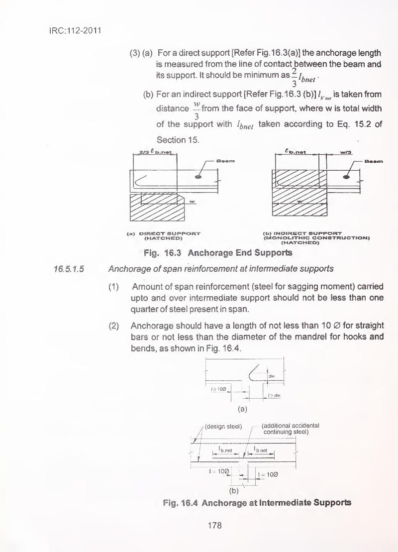
IRC:112-2011
(3) (a) For a direct support [Refer Fig. 16.3(a)] the anchorage length
is measured from the line of contact between the beam and
its support It should be minimum as_/^^^^
.
(b) For an indirect support [Refer Fig. 16.3 (b)] /^.^^ is taken from
distance --from the face of support, where w is total width3
of the support with taken according to Eq. 15.2 of
Section 15.
w£3
Fig. 16.3 Anchorage End Supports
16.5.1.5 Anchorage ofspan reinforcement at intermediate supports
(1) Amount of span reinforcement (steel for sagging moment) canried
upto and over intermediate support should not be less than one
quarter of steel present in span.
(2) Anchorage should have a length of not less than 1 0 0 for straight
bars or not less than the diameter of the mandrel for hooks and
bends, as shown in Fig. 16.4.
/>1O0
-I-
l>dm
(a)
(design steei) (additionai accidental
continuing steel)
' b.net -
1-100 = 100
(b)
Fig. 16.4 Anchorage at Intermediate Supports
178
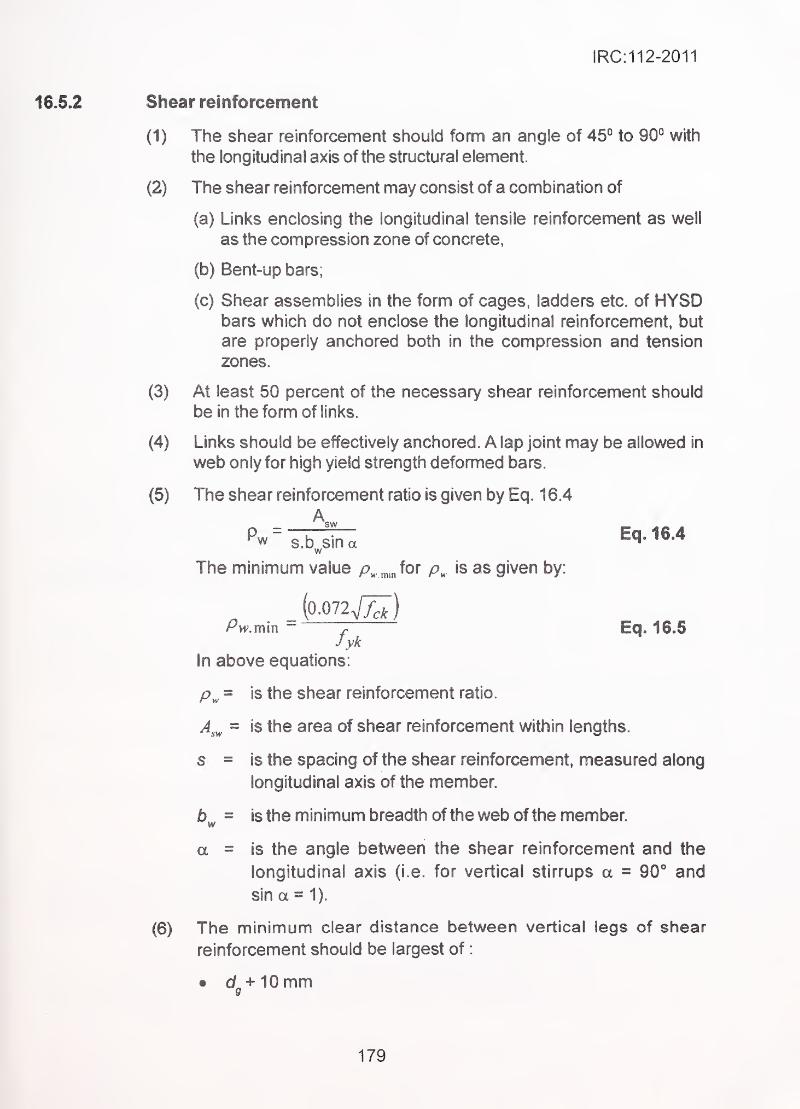
IRC:112-2011
Shear reinforcement
(1) The shear reinforcement should form an angle of 45° to 90° with
the longitudinal axis of the structural element.
(2) The shear reinforcement may consist of a combination of
(a) Links enclosing the longitudinal tensile reinforcement as well
as the compression zone of concrete,
(b) Bent-up bars;
(c) Shear assemblies in the form of cages, ladders etc. of HYSDbars which do not enclose the longitudinal reinforcement, but
are properly anchored both in the compression and tension
zones.
(3) At least 50 percent of the necessary shear reinforcement should
be in the form of links.
- (4) Links should be effectively anchored. A lap joint may be allowed in
web only for high yield strength deformed bars.
(5) The shear reinforcement ratio is given by Eq. 16.4
A,Pw ~ o K oir. Eq, 16.4w s.D sin a ;
^w
The minimum value for is as given by: .
-
_ (o.072Vy^)Pvv.min ~
. Eq. 16=5fyk
In above equations:
p^ = is the shear reinforcement ratio.
A^^ = is the area of shear reinforcement within lengths.
s = is the spacing of the shear reinforcement, measured along
longitudinal axis of the member.
= is the minimum breadth of the web of the member.
a = is the angle between the shear reinforcement and the
longitudinal axis (i.e. for vertical stirrups a = 90** and
sin a = 1).
(6) The minimum clear distance between vertical legs of shear
reinforcement should be largest of
:
• d+10mm9
179
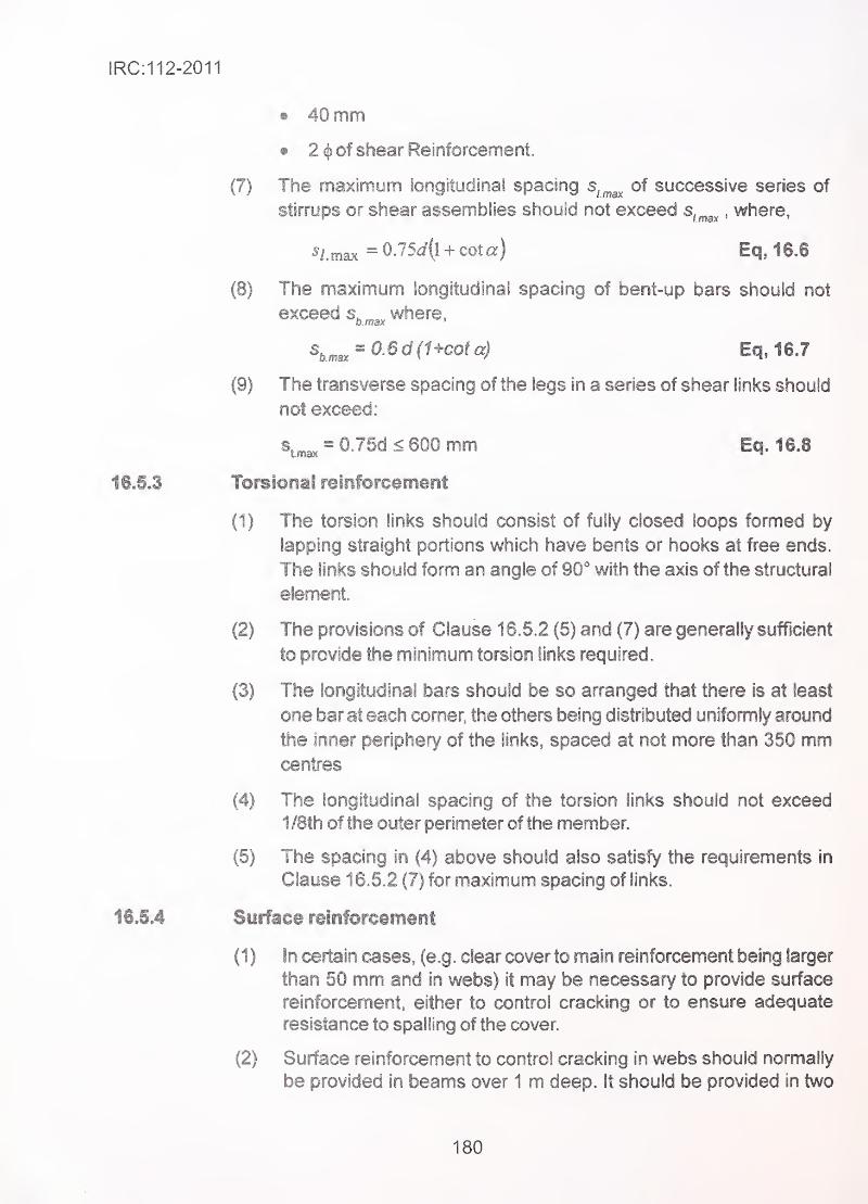
IRC:112-2011
(7)
(8)
(9)
16,5J Torsional reinforcement
(1) The torsion links should consist of fully closed loops formed by
lapping straight portions which have bents or hooks at free ends.
The links should form an angle of 90* with the axis of the structural
©Ismsnt.
(2) The provisions of Clause 1 6.62 (5) and (7) are generally sufficient
to provide the minimum torsion links required.
(3) The longitudinal bars should be so arranged that there is at least
one bar at each corner, the others being distributed unlfomily around
the inner periphery of the links, spaced at not more than 350 mmcentres
(4) The iongftudinai spacing of the torsion links should not exceed
1 /8th of the outer perimeter of the member.
(5) The spacing in (4) above should also satisfy the requirements in
Clause 1 6.5.2 (7) for maximum spacing of links.
16,5J Suiface reinforcement
(1 ) in certain cases, (e.g. clear cover to main reinforcement being larger
than 50 mm and in webs) it may be necessary to provide surface
reinforcement, either to control cracking or to ensure adequate
resistance to spalling of the cover.
(2) Surface reinforcement to control cracking in webs should normally
be provided in beams over 1 m deep, it should be provided in two
® 40 mm
• 2 «|) of shear Reinforcement.
The maximum longitudinal spacing s,^^^ of successive series of
stirrups or shear assemblies should not exceed s,^^^,where,
5/ max =0.75(i(l + cota) • Eq, 16.6
The maximum longitudinal spacing of bent-up bars should not
exceed s.„„ where,0. max '
,
\n,sr^ 0.6 d (Ucot a) Eq,16.7
The transverse spacing of the legs in a series of shear links should
not exceed:
s = 0.75d < 600 mm Eq. 16.8
180
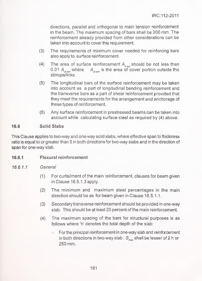
IRC:112-2011
, directions, parallel and orthogonal to main tension reinforcement
in the beam. The maximum spacing of bars shall be 200 mm. Thereinforcement already provided from other considerations can be
taken into account to cover this requirement.
(3) The requirements of minimum cover needed for reinforcing bars
also apply to surface reinforcement.
(4) The area of surface reinforcement yA^^^ should be not less than
0 0''-^ctext
where A^^^^^ is the area of cover portion outside the
stirrups/links.
(5) The iongitudinai bars of the surface reinforcement may be taken- into account as a part of longitudinal bending reinforcement and
the transverse bars as a part of shear reinforcement provided that
they meet the requirements for the arrangement and anchorage of
these types of reinforcement.
(6) Any surface reinforcement in prestressed beams can be taken into
account while calculating surface steel as required by (4) above.
16.6 Solid Slabs
This Clause applies to two-way and one-way solid slabs, where effective span to thickness
ratio is equal to or greater than 5 in both directions for two-way slabs and in the direction of
span for one-way slab.
16.6.1 Fiexural reinforcement
16 6.1.1 General
(1 ) For curtailment of the main reinforcement, clauses for beam given
in Clause 16.5.1 .3 apply.
(2) The minimum and maximum steel percentages in the main
direction should be as for beam given in Clause 16.5.1 . 1
.
(3) Secondary transverse reinforcement should be provided in one-way
slab. This should be at least 20 percent of the main reinforcement.
(4) The maximum spacing of the bars for structural purposes is as
follows where 'h' denotes the total depth of the slab:
- For the principal reinforcement in one-way slab and reinforcement
in both directions in two-way slab : S^^^ shall be lesser of 2 h or
250 mm.
181
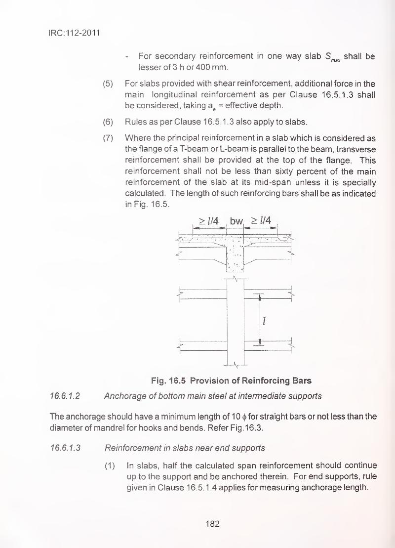
IRC:112-2011
(5)
(6)
(7)
For secondary reinforcement in one way slab Slesser of 3 h or 400 mm.
max shall be
For slabs provided with shear reinforcement, additional force in the
main longitudinal reinforcement as per Clause 16.5.1.3 shall
be considered, taking = effective depth.
Rules as per Clause 16.5.1 .3 also apply to slabs.
Where the principal reinforcement in a slab which is considered as
the flange of aT-beam or L-beam is parallel to the beam, transverse
reinforcement shall be provided at the top of the flange. This
reinforcement shall not be less than sixty percent of the main
reinforcement of the slab at its mid-span unless it is specially
calculated. The length of such reinforcing bars shall be as indicated
in Fig. 16.5.
>II4 bw >l/4
t
16.6.1,2
Fig. 16.5 Provision of Reinforcing Bars
Anchorage of bottom main steel at intermediate supports
The anchorage should have a minimum length of 1 0 cj) for straight bars or not less than the
diameter of mandrel for hooks and bends. Refer Fig. 16.3.
16.6.1.3 Reinforcement in slabs near end supports
(1) In slabs, half the calculated span reinforcement should continue
up to the support and be anchored therein. For end supports, rule
given in Clause 16.5.1.4 applies for measuring anchorage length.
182
IRC:112-2011
(2) The anchorage of reinforcement should be capable of resisting a
tensile force
:
F.-V^,.^ + N,^, Eq.16.9a
where
N^^ is the axial tensile force in the slab50
d is effective depth of slab and
Of is as defined in C!ause16.5.1 .3.
(3) Where partial fixity occurs along one side of slab, but is not taken
into account in the analysis, the top reinforcement should be capable
of resisting not less than 25 percent of the maximum moment in
the span. This reinforcement should be provided for length of
not less than 0.2 times the adjacent span measured from the inner
face of the support.
Reinforcement at the free edges
(1) Stiffening of unsupported edge
Unsupported slabs carrying vehicular live load (or accidental wheel
load) shall be suitably stiffened as indicated below:
(a) Each unsupported edge of a slab parallel to traffic and beyond
the clear road width, shall be so stiffened as to give a resisting
moment for any type of flexure equal to or in excess of that of a
500 mm strip of the main roadway slab adjoining the edge. In
case of a roadway slab of uniform depth, whether the
reinforcement is one-way (parallel to or across the traffic) or
two-way, the maximum resisting moment of the roadway slab
adjoining the edge and given by a 500 mm strip in any direction
shall be taken as the criterion for the resisting moment of the
stiffened edge. When the roadway slab is of varying depth in
the direction parallel to the edge concemed, the stiffening at
any particular point along the length of edge shall be adjusted
according to the resisting moment of the 500 mm adjacent strip
at that particular point.
Stiffening of edge may consist of a reinforced kerb section, or
an edge stiffening beam. Where concrete crash barriers
are provided over the full length of free edge, they may be
considered as stiffening beams.
183
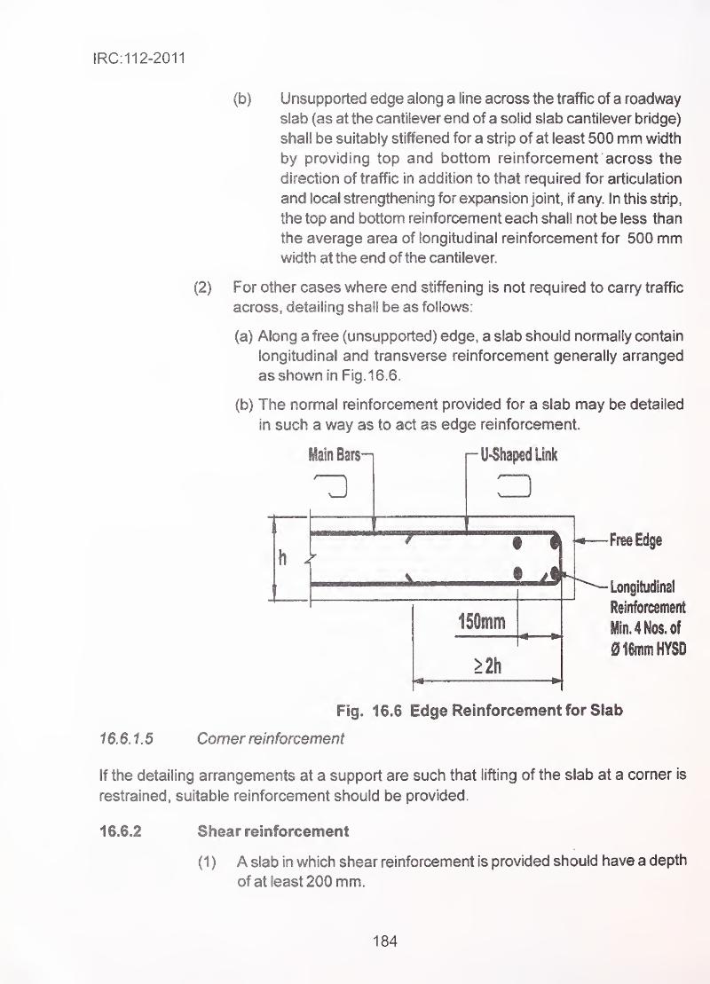
IRC:112-2011
(2)
(b) Unsupported edge along a line across the traffic of a roadway
slab (as at the cantilever end of a solid slab cantilever bridge)
shall be suitably stiffened for a strip of at least 500 mm width
by providing top and bottom reinforcement across the
direction of traffic in addition to that required for articulation
and local strengthening for expansion joint, if any. In this strip,
the top and bottom reinforcement each shall not be less than
the average area of longitudinal reinforcement for 500 mmwidth at the end of the cantilever.
For other cases where end stiffening is not required to carry traffic
across, detailing shall be as follows:
(a) Along a free (unsupported) edge, a slab should normally contain
longitudinal and transverse reinforcement generally arranged
as shown in Fig. 16.6.
(b) The normal reinforcement provided for a slab may be detailed
in such a way as to act as edge reinforcement.
Main Barsn U-ShapedUnk
3h >
150mm
>2h
' Longitudinal
MIn. 4 Nos. of
016mmHYSD
16.6.1.5
Fig. 16.6 Edge Reinforcement for Slab
Comer reinforcement
If the detailing arrangements at a support are such that lifting of the slab at a corner is
restrained, suitable reinforcement should be provided.
16.6.2 Shear reinforcement
(1 ) A slab in which shear reinforcement is provided should have a depth
of at least 200 mm.
184
IRC:112-2011
(2) In detailing the shear reinforcement, Clause 16,5.2 applies except
where modified by the following rules.
(3) In slabs if V^^ < ^ (Refer Section 1 2). the shear reinforcement
may consist entirely of bent-up bars or of shear assemblies.
(4) The maximum longitudinal spacing of bent-up bars is S^^^ - d.
(5) The maximum longitudinal spacing of successive series of links is
given by :
•
s^^^=0J5d{l + cota) Eq. 16J0
where a is inclination of shear reinforcement.
Corbels
General .
(1) Corbels may be designed by using strut and tie model The
inclination of strut with respect to axial direction of the member to
which corbel is attached, should lie between 22® and 45°
(2) The reinforcement, corresponding to the ties designed using strut
and tie model should be fully anchored beyond the node under the
bearing plate, by using U-hoops or anchorage devices such as
welding to a cross bar, unless a length!^^^^^
is available between the
node and the front of the corbel./^^,^,^
should be measured beyond
the full width of compressive strut. It shall be fully anchored at the
other end in the body of the member to which the bracket is attached.
(3) in corbels with ^ 0.5 closed horizontal or inclined links with
area A^^.^^ shall be provided in addition to the main tension
reinforcement as shown in Fig. 16.7(a) or Fig. 16.7(c), where:
\«>0-25A_, Eq. 16.11
(4) In corbels with a^ > 0.5 h^ and F^^>y^^^ (Refer Section 10) closed
vertical stirrups with areaA^^^^p shall be provided in addition to the
main tension reinforcement as shown in Fig. 16.7 (b), where:
^sstirrup > 0.5 F.Jfya Eq. 16.12
185
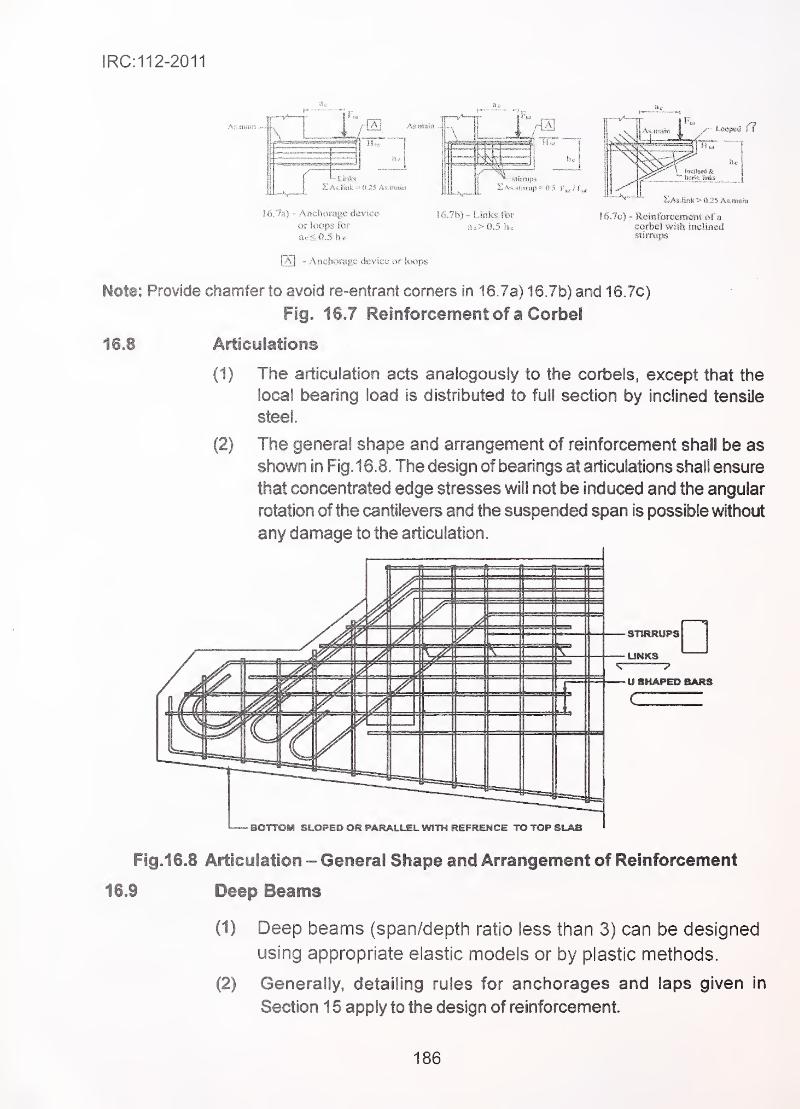
IRC:112-2011
-Lmkis
16.%) - Anchorage device-
or !(X!ps ior;^
ac<0.5he-
[S] - Anchorage device or kwps
16.7c) - Relnforceifteftt 0f a
corbel wish inclined
Note: Provide chamfer to avoid re-entrant corners in 16.7a) 16Jb) and 16.7c)
Fig. 1SJ Reinforcement of a Corbel
16J Articulations
(1) The articulation acts analogously to the corbels, except that the
local bearing load is distributed to full section by inclined tensile
steel
(2) The general shape and arrangement of reinforcement shall be as
shown in Fig. 16.8. The design of bearings at articulations shall ensure
that concentrated edge stresses will not be induced and the angular
rotation of the cantilevers and the suspended span is possible without
any damage to the articulation.
' BOTTOM SLOPED OR PARALLet WITH REFRENCE TO TOP 81AB
Fig.1 6.8 Articulation - General Shape and Arrangement of Reinforcement
16.9 Deep Beams
(1) Deep beams (span/depth ratio less than 3) can be designed
using appropriate elastic models or by plastic methods.
(2) Generally, detailing rules for anchorages and laps given in
Section 1 5 apply to the design of reinforcement.
186
IRC:112-2011
(3) The reinforcement corresponding to the ties, designed using strut
and tie model, should be fully anchored beyond the nodes by
' bending up the bars, by using U hoops or by anchorage devices
unless a sufficient length is available between the node and the
end of the beam permitting an anchorage length of
. (4) Deep beams should normally be provided with a distributed
reinforcement on both sides, the effect of each being equivalent to
that of an orthogonal mesh with a reinforcement ratio of at least
0.15 percent in both directions, but not less than 1 50 mm^ per metre
in each face and in each direction. The spacing shall not exceed
200 mm.
16.10 Members with Unbonded Tendons,
,-
For members with only unbonded tendons, requirements for reinforced concrete elements
apply.
For members with a combination of bonded and unbonded tendons, requirements for
prestressed concrete members with bonded tendons apply.
Crack width may be calculated according to Clause 1 2.3.4 and Clause12.3.5. Alternatively,
limiting maximum bar size or spacing as per Clause12.3.6 may be deemed to satisfy
crack control criteria for reinforced concrete members.
16.11 Concentrated Forces'
16.11.1 General
(1 ) Where one or more concentrated forces act at the end of a member
or at the intersection oftwo structural members, local supplementary
reinforcement should be provided capable of resisting the transverse
tensile forces caused by these forces.
(2) This supplementary reinforcement may consist of links or of layers
of reinforcement bent in the shape of hair pins.
(3) For uniform distribution of load on area A^^, (Fig. 16.9), the
concentrated resistance force can be detemnined as follows:
187
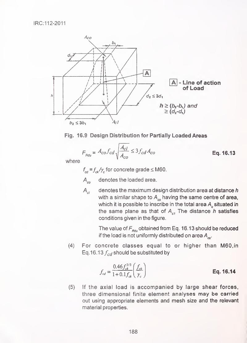
IRC:112-2011
Aj - Line of actionof Load
h > (ih'b^) and
b2 < 35|
Fig^ 16J Design Distribution for Partially Loaded Areas
where
CO Eq. 16.13
(4)
(5)
=f^/Zc for concrete grade < M60.
A„ denotes the loaded area.CO
A^i denotes the maximum design distribution area at distance h
with a similar shape to having the same centre of area,
which it is possible to inscribe in the total area situated in
the same plane as that of A^^ The distance h satisfies
conditions given in the figure.
The value of F^^^ obtained from Eq. 16.13 should be reduced
if the load is not uniformly distributed on area A^.
For concrete classes equal to or higher than M60,in
Eq.16.13 /^^ should be substituted by
J'^'i'1 + 0.1/,
Eq. 16.14
If the axial load is accompanied by large shear forces,
three dimensional finite element analyses may be carried
out using appropriate elements and mesh size and the relevant
material properties.
188
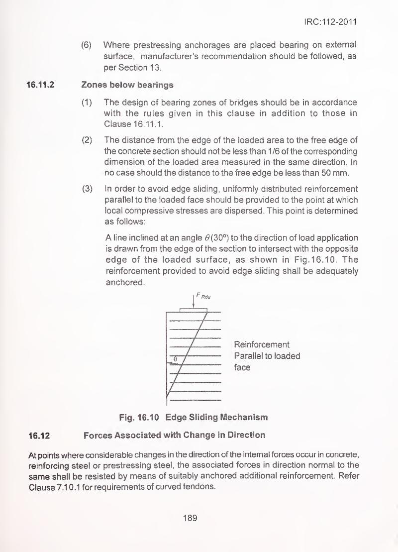
IRC:112-2011
(6) Where prestressing anchorages are placed bearing on external
surface, manufacturer's recommendation should be followed, as
per Section 13. ..
16J1.2 Zones below bearings
(1) The design of bearing zones of bridges should be in accordance
with the rules given in this clause in addition to those in
Clause 16.11 1.
(2) The distance from the edge of the loaded area to the free edge of
the concrete section should not be less than 1 /6 of the corresponding
dimension of the loaded area measured in the same direction, in
no case should the distance to the free edge be less than 50 mm.
(3) In order to avoid edge sliding, uniformly distributed reinforcement
parallel to the loaded face should be provided to the point at which
local compressive stresses are dispersed. This point is determined
as follows:
A line inclined at an angle ^(30°) to the direction of load application
is drawn from the edge of the section to intersect with the opposite
edge of the loaded surface, as shown in Fig. 16. 10. Thereinforcement provided to avoid edge sliding shall be adequately
anchored.
Reinforcement
Parallel to loaded
face ..-
Fig. 16.10 Edge Sliding Mechanism
16.12 Forces Associated with Change in Direction
At points where considerable changes in the direction of the internal forces occur in concrete,
reinforcing steel or prestressing steel, the associated forces in direction normal to the
same shall be resisted by means of suitably anchored additional reinforcement. Refer
Clause 7.1 0,1 for requirements of curved tendons.
189
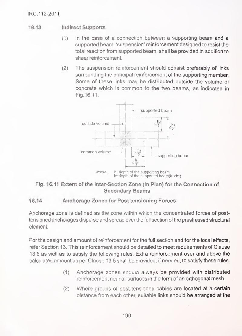
IRC:112-2011
16.13 Indirect Supports
(1) In the case of a connection between a supporting beam and a
supported beam, 'suspension' reinforcement designed to resist the
total reaction from supported beam, shall be provided in addition to
shear reinforcement.
(2) The suspension reinforcement should consist preferably of links
surrounding the principal reinforcement of the supporting member.
Some of these links may be distributed outside the volume of
concrete which is common to the two beams, as indicated in
Fig. 16.11.
outside volume
supported beam
common volume
where,
hi
hi
h2
supporting beam
hi depth of the supporting beamh2 depth of the supported beam(hi>h2)
Fig. 16.11 Extent of the Inter-Section Zone (In Plan) for the Connection of
Secondary Beams
16.14 Anchorage Zones for Post tensioning Forces
Anchorage zone is defined as the zone within which the concentrated forces of post-
tensioned anchorages disperse and spread over the full section of the prestressed structural
element.
For the design and amount of reinforcement for the full section and for the local effects,
refer Section 13. This reinforcement should be detailed to meet requirements of Clause
13,5 as well as to satisfy the following rules. Extra reinforcement over and above the
calculated amount as per Clause 13.5 shall be provided, if needed, to satisfy these rules.
(1) Anchorage zones should always be provided with distributed
reinforcement near all surfaces in the form of an orthogonal mesh.
(2) Where groups of post-tensioned cables are located at a certain
distance from each other, suitable links should be anranged at the
190
IRC:112-2011
ends of the members, as a protection against splitting away ofgroups.
(3) All reinforcement should be fully anchored.
(4) Where a stnjt and tie model has been used to determine the transverse
tensile force, the following detailing rules shall be followed:
(a) The steel area actually required to provide the tie force, acting
at its design strength, shall be distributed in accordance with
the actual tensile stress distribution, i.e. over a length of the
block approximately equal to its greatest lateral dimension.
(b) Closed stirrups should be used for anchorage of ties.
191
IRC:112-2011
SECTION 17 DUCTILE DETAILING FOR SEISMIC RESISTANCE
17.1 General
(1) Ductile detailing shall be carried out for bridges located in zones III,
IV and V of seismic zone map of IRC :6.
(2) The rules of this Section apply to bridges designed for ductile
behaviour for improving their seismic resistance and aim to ensure
a minimum level of curvature/rotation ductility at the plastic hinges.
These are supplementary to the rules given in Sections 15 &>16
which remain applicable, unless specifically modified in this Section.
(3) In general, plastic hinge formation is not allowed in the
superstructure. Therefore there is no need for application of detailing
mies of this Section for the superstructure.
(4) Bridge foundation system shall be designed, as far as practicable,
to remain elastic under design seismic action and foundations shall
not be intentionally used as a means of energy dissipation through
phenomenon of hysteresis.
(5) The bridge shall be proportioned and detailed in such a manner
that plastic hinges can occur only at pre-determined locations and
not at any other locations.
(6) Where longitudinal reinforcement is curtailed (e.g. in tali piers)
potential of formation of hinge shall be avoided just beyond the
point of curtailment.
17.2 Concrete Piers/Columns'
17.2.1 Confinement
17.2.1.1 General requirements
(1) Within the potential plastic hinge regions, ductile behaviour of the
compression zone of concrete shall be ensured by providing
confinement of concrete.
(2) Confinement is implemented through rectangular hoops and/or
cross-ties or through circular hoops or spirals.
(3) In potential hings regions where the normalised axial force
exceeds the limit:
NED/Acfck>OM Eq. 17.1
192
IRC:112-2011
confinement of the compression zone in accordance with
Clausel 7.2.1 .4 shall be provided.
(4) The required quantity of confining reinforcement expressed as ratio
co^j is calculated as per Eq. 17.2 and shall satisfy the requirements
of Clause 17.2.1.2:
(^wd = Pwfyd I fed • Eq. 17.2
where
(a) In rectangular sections:
is the volumetric ratio of transverse reinforcement defined as:
P^^-ifj Eq.17.3
where
A^^. - is the area of the stirrups and ties in one direction of
confinement.
Si = is the spacing of hoops or ties in the longitudinal direction
^ = is the dimension of the concrete core perpendicular to the
, .,
direction of the confinement under consideration, measured
to the outside of the perimeter hoop.
'
-
'
(b) In circular sections:
Volumetric ratio of the hoops/spiral reinforcement relative to the
concrete core is given by Eq. 17.4:
- ^"^^PPw - ^ ^ .
' Eq. 17.4
where
4^ is the area of the spiral or hoop bar
D^p is the diameter of the spiral or hoop bar
Si is the spacing of these bars
Note: Bars inclined at an angle a to the transverse direction shall be assumed to contribute
to the total area A^^ or A^^ in Eq. 1 7.3 by their area multiplied by cos a.
17.2.1.2 Minimum confining reinforcement
(1) Confinement is provided by use of rectangular loops and/or cross
ties for rectangular sections or through circular hoops or spirals for
circular sections.
193
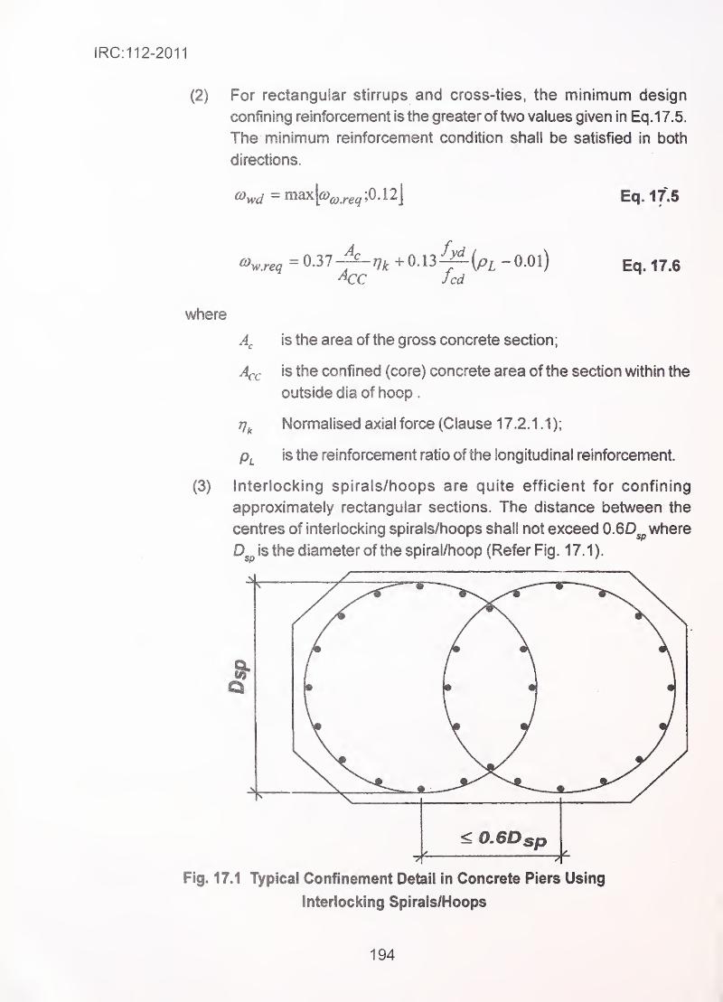
IRC:112-2011
(2) For rectangular stirrups and cross-ties, the minimum design
confining reinforcement is the greater oftwo values given in Eq.17.5,
The minimum reinforcement condition shall be satisfied in both
directions.
Eq. if
3
^w.req = 0-37
A:c Jed
where j
is the area of the gross concrete section
;
A^fj is the confined (core) concrete area of the section within the
outside dia of hoop .
77^ Normalised axial force (Clause 17.2.1,1);
is the reinforcement ratio of the longitudinal reinforcement.
Interlocking spirals/hoops are quite efficient for confining
approximately rectangular sections. The distance between the
centres of interlocking spirals/hoops shall not exceed 0.6D^ where
is the diameter of the spiral/hoop (Refer Fig. 17.1).
(3)
<0.6D
Fig. 17.1 Typical Confinement Detail in Concrete Piers Using
Interlocking Spirals/Hoops
194
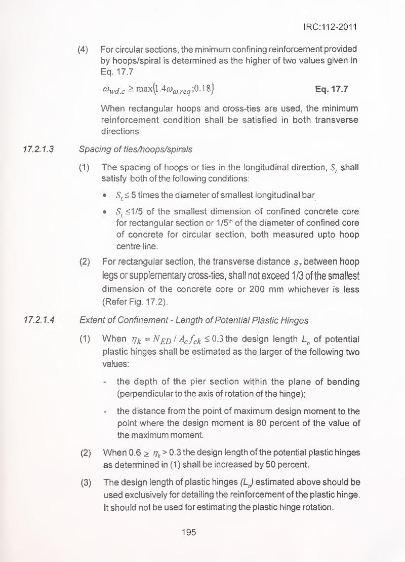
IRC:112-2011
(4) For circular sections, the minimum confining reinforcement provided
by hoops/spiral is determined as the higher of two values given in
Eq. 17.7
^y^^.^ >max(l.4£y^.;.e^;0.18) Eq.17.7
When rectangular hoops and cross-ties are used, the minimum
reinforcement condition shall be satisfied in both transverse
directions
17.2.1.3 Spacing of ties/hoops/spirals
(1) The spacing of hoops or ties in the longitudinal direction, shall
satisfy both of the following conditions:
;
• Sj < 5 times the diameter of smallest longitudinal bar
• Si <1/5 of the smallest dimension of confined concrete core
for rectangular section or 1/5^^ of the diameter of confined core
of concrete for circular section, both measured upto hoop
centre line.
(2) For rectangular section, the transverse distance Sj between hoop
legs or supplementary cross-ties, shall not exceed 1/3 of the smallest
dimension of the concrete core or 200 mm whichever is less
(Refer Fig. 17.2).
17.2.1A Extent of Confinement - Length of Potential Plastic Hinges
(1) When T]^ = N^j^l Acfck ^0.3 the design length of potential
;plastic hinges shall be estimated as the larger of the following two
values:
- the depth of the pier section within the plane of bending
(perpendicular to the axis of rotation of the hinge);
- the distance from the point of maximum design moment to the
point where the design moment is 80 percent of the value of
the maximum moment.
(2) When 0.6 > > 0.3 the design length of the potential plastic hinges
as determined in (1) shall be increased by 50 percent.
(3) The design length of plastic hinges estimated above should be
used exclusively for detailing the reinforcement of the plastic hinge.
It should not be used for estimating the plastic hinge rotation.
195
I
IRC:112-2011
4s-
—
A\—
-
-\—
—
f
4StiJ/
'' /
B
S & S j2 • Distance between Stirrups legs or Cross-Ties
S ji S j2 = min (bmin/3, 200mm)
3s T2
9s 11
V -,,
i
i
1 \
\
4 — i
/. yi
min
A: 4 Closed Overlapping Stirrups
B: 3 Closed Overlapping Stirrups Plus Cross-Ties
C: Closed Overlapping Stirrups Plus Cross-Ties
Fig. 17.2 Typical Confinement Detail in Concrete Piers with Rectangular
Section using Overlapping Rectangular Stirrups and Cross-Ties
196
IRC:112-2011
(4) When confinement is required, the reinforcement specified in
Clause 17 2.1.2 shall be provided over the entire length of the
plastic hinge. Outside the length of the hinge, the transverse
reinforcement may be gradually reduced to that required by other
criteria. The amount of transverse reinforcement provided over an
additional length adjacent to the theoretical end of the plastic
hinge, shall not be less than 50 percent of the confining reinforcement
required in the region of plastic hinge.
(5) The confinement shall extend at least upto the length where the
value of the compressive strain exceeds O.Se^^^
Buckitng of longitudinal compression reinforcement
(1) Buckling of longitudinal reinforcement shall be avoided along the
length of the potential hinge areas, even after several hysterics
cycles in post-yield region of stress-strain diagram of steel.
To meet this requirement, all main longitudinal bars should be
restrained against outward buckling by transverse reinforcement
(hoops or cross-ties) perpendicular to the longitudinal bars at a
(longitudinal) spacing not exceeding five times d^i , the
diameter of the smallest longitudinal bars.
(2) Along straight section boundaries, restraining of longitudinal bars
should be achieved in either one of the following ways:
(a) Through a perimeter tie engaged by intermediate cross-ties at
alternate locations of longitudinal bars, at transverse (horizontal)
spacing not exceeding 200 mm. The cross-ties shall have
ISS** hooks at one end, and 1 35*^ or 90® bend at the other end.
Bends of QO^'arenotpemiitted if rj^is greater than 0.3. Cross ties
having 135° on both ends may consist of two lapped spliced
pieces. In sections of large dimensions the perimeter tie may
be spliced using appropriate lapping length combined with
hooks; or
(b) Through overlapping closed ties arranged so that every corner
bar and at least every alternate intemai longitudinal bar is
engaged by a tie leg. The transverse (horizontal) spacing of
the tie legs should not exceed 200 mm.
197
IRC:112-2011
17.2.3
17.2.4
(3) The minimum amount of transverse ties shall be determined as
follows:
4 is the area of one tie leg, in mm^.
Sj IS the transverse distance between tie legs) in m;
lA^ is the sum of the areas of the longitudinal bars restrained by the
tie, in mm^;
fyt is the yield strength of the tie; and
fy, is the yield strength of the longitudinal reinforcement.
Other ryies
(1) Due to the possibility of loss of concrete cover in the plastic hinge
region, the confining reinforcement shall be anchored by 135® hooks
around a longitudinal bar. Where 90*^ bend is used as per
Clasue 17.2.2(2), the bar shall extend by minimum 10 diameters
into the core concrete.
(2) Similar anchoring or a full strength weld is required for the lapping
of spirals or hoops within potential plastic hinge regions. In this
case laps of successive spirals or hoops, when located along the
perimeter of the member, should be staggered.
(3) Splicing by lapping or welding of longitudinal reinforcement is not
allowed within the plastic hinge region.
Hollow piers
(1 ) The ratio of the clear width b to the thickness h of the walls, in the
plastic hinge region (length in accordance with Clause 17.2.14)
of hollow piers with a single or multiple box cross-section, should
not exceed 8.
(2) For hollow cylindrical piers the ratio of clear inside diameter, to
thickness of wail shall not exceed 8.
(3) In piers with simple or multiple box section and when the value of
the ratio Hk does not exceed 0.2. there is no need for verification
of the confining reinforcement in accordance with Clause 17.2.1,
provided that the requirements of controlling buckling of longitudinal
bars given in Clause 17.2.2 are met.
Eq.17.8
where
198
IRC:112-2011
17.3 Foundations
17.3.1 ' Generai
Spread foundations (such as footings, rafts), wells, box-type caissons, etc. shall nof
enter the plastic range under the design seismic action and hence do not require any
special ductile detailing of reinforcement.
17.3.2 Pile foundations
(1) When it is not feasible to avoid localised hinge formation in the
piles by designing pier to form hinges earlier (capacity protection
method), integrity and ductile behaviour of piles shall be ensured
as given below.
(2) The following locations along the pile should be treated as potential
plastic hinges.
(a) At the pile heads adjacent to the pile cap, when the rotation of
the pile cap about a horizontal axis transverse to the seismic
action is restrained by the large stiffness of the pile group.
(b) At location of maximum bending moment in piles taking into
account soil-pile interaction, using appropriate stiffnesses of
' ' ' both pile, pile cap and soil. "
^ -
•
'
'
(c) At the interfaces of soil layers with markedly different shear
deformability (e.g. change of strata).
(3) At location of type 2(a), confining reinforcement of the amount
specified in Clause 17.2.1.1 along a vertical length equal to 3 times
the pile diameter, shall be provided.
(4) Unless a more accurate analysis is made, longitudinal as well as
confining reinforcement of the same amount as that required at the
pile head, shall be provided over a length of two pile diameters on
each side of the point of maximum moment at location of type 2(b)
and of each side of the interface at locations of type 2(c).
199
IRC:112-2011
SECTION 18 MATERIALS, QUALITY CONTROLAND WORKMANSHIP
18.1 General
This Section gives specifications of materials to be used in construction of new concrete
bridges and standards to which they should conform. For new construction, the Indian
Standards, refenred below or any specific international standards governing these materials,
shall be the latest revisions thereof. The tables and notes below table given in this Section
are reproduced for ready reference from the relevant IS Codes listed inAnnexureA-3.
For assessment of properties of materials in existing bridges, the standards in force at the
time of their construction or the actual standards used for procurement, shall be referred
to. The time dependency of properties shall also be taken into account in such cases.
18.2 Untensioned Steel
18.2.1 Specification and grades
Reinforcement shall consist of hot roiled, thermo-mechanical or heat-treated rods, de-coiled
rods, or cold worked steel conforming to relevant Indian Standards. The main definitive
properties and grades are given in Table 18.1. Steel conforming to any other international
standard may be used provided its strength, elongation, chemical composition and bondin concrete, are not inferior to those of Indian Standards. The grade designations are as
adopted by the relevant standards.
The minimum strength, as specified in relevant BIS Standards, which is either the yield
strength in case of mild steel or 0.2 percent proof strength in case of high yield steel is
notionaliy taken as the characteristic strength /..
18.2.2 Other characteristics
Other important characteristics such as bendability (established by bend and re-bend test),
weldability (established by equivalent carbon content) and bond characteristics in concrete
should be as specified in IS 432 and IS 1786.
The dimensional tolerances and characteristics of ribs for HYSD steel should be as perIS 432 and IS 1786.
18.2.3 Products with improved corrosion resistance
Reinforcing steel bars with corrosion resistance improved by any of the following methods,can be used as untensioned reinforcement, provided they meet the minimum strength,
proof stress and elongation characteristics as specified for untensioned reinforcement.
200
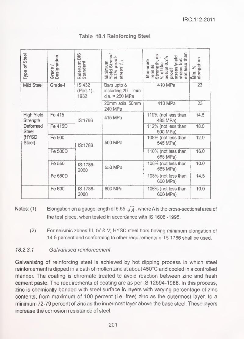
Table 18,1 Reinforcing Steel
IRC:112-2011
Type
of
Steelc
^1
<2ffl
P"I11 Yield
Stress/
n
7%
proof-
stress
Tensile Strength,
as
%of
the
actual
0.2%
proof
stress/vleld
Stress
but
not
less
than
Min.
% elongation
Mild Steel Grade-! IS:432
(Part-1)~
1982
Bars upto &including 20 mmdie. = 250 MPa
410 MPa . 23
^urnrn mia ournrn
240 MPa* 1 U IVira ZJ
High Yield
Strength
Deformed
Steel
(HYSDSteel)
Fe415!S:1786
415 MPa110% (not less than
485 MPa)14.5
Fe415D 112% (not less than
500 MPa)18.0
re ouu
18:1786500 MPa
108% (not less than
545 MPa)12.0
re DUUD 110% (not less than
565 MPa)16.0
Fe 550 IS: 1786"
2000550 MPa
106% (not less than
585 MPa)10.0
Fe 550D 108% (not less than
600 MPa)14.5
Fe600 18:1786-
2000
600 MPa 106% (not less than
600 MPa)10.0
Notes: (1 ) Elongation on a gauge length of 5.65^ , whereA is the cross-sectional area of
the test piece, when tested in accordance with IS 1608 -1 995.
(2) For seismic zones III, IV & V; HYSD steel bars having minimum elongation of
14.5 percent and conforming to other requirements of IS 1786 shall be used.
1 8. 2. 3. 1 Galvanised reinforcement
Galvanising of reinforcing steel is achieved by hot dipping process in which steel
reinforcement is dipped in a bath of molten zinc at about 450**C and cooled in a controlled
manner. The coating is chromate treated to avoid reaction between zinc and fresh
cement paste. The requirements of coating are as per IS 12594-1988. In this process,
zinc is chemically bonded with steel surface in layers with varying percentage of zinc
contents, from maximum of 100 percent (i.e. free) zinc as the outermost layer, to a
minimum 72-79 percent of zinc as the innermost layer above the base steel. These layers
increase the corrosion resistance of steel.
201
IRC:112-2011
The strength as well as elongation and bond properties are not adversely affected by
galvanising.
18.2.3.2 Epoxy-coated reinforcement
Reinforcing bars confonning to IS 1 786 can be coated by fusion bonded epoxy conforming
to IS 13620-1993.
The fusion-bonded epoxy coating forms a continuous layer (free of holidays) which has
high electrical resistance and prevents setting up of corrosion cells between steel and the
surrounding electrolytic micro-environment of moist concrete. It also provides physical
barrier between steel and the harmful elements from environmental sources, controlling
their rate of penetration. On the other hand, the discontinuities in the barrier (holidays)
have the tendency to concentrate the corrosion currents in these areas, leading to faster
localised corrosion. The overall effect of coating is, however, beneficial in increasing the
corrosion resistance of the structure, provided the occurrence of holidays is controlled.
The bond between reinforcement and concrete is lowered by upto 20 percent ofthe bond
without such coating. In detailing of steel the lap lengths and anchorage lengths shall be
increased by 25 percent.
18.2.3.3 Stainless steel reinforcement
Properties of stainless steel reinforcement shall not be inferior to those of carbon steel
reinforcement of corresponding strength class. For bond properties, the relevant code
may be referred or they may be established on the basis of tests.
Note: Till such time as the Indian Standard for stainless steel reinforcement is
available, the British Standard 88:6744:2001,may be referred.
18.3 Prestressing Steel
18.3.1 Specification and grades
Prestressing steel in the form of plain or indented wires, stress-relieved multi-ply strands,
or high tende steel bars, shall conform to standards given in Table 18.2 subject to the
stipulations given in Clause 1 8.3.2.
202
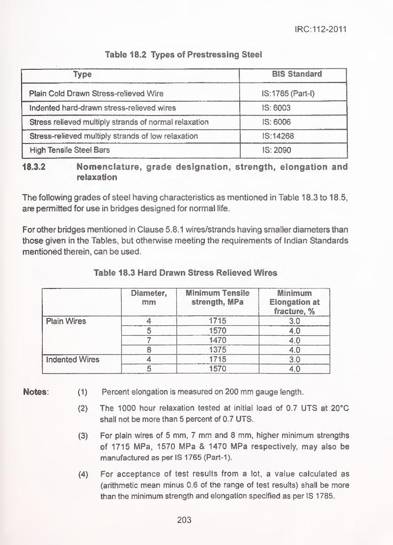
IRC:112-2011
Table 18.2 Types of Prestressing Steel
BIS Standard
Plain Cold Drawn Stress-relieved Wire IS: 1785 (Part-I)
indented hard-drawn stress-relieved wires IS: 6003
Stress relieved multiply strands of normal relaxation IS: 6006
Stress-relieved multiply strands of low relaxation IS:14268
High Tensile Steel Bars IS: 2090
18.3.2 Nomenclature, grade designation, strength, elongation andrelaxation
The following grades of steel having characteristics as mentioned in Table 18.3 to 18.5,
are permitted for use in bridges designed for normal life.
For other bridges mentioned in Clause 5.8.1 wires/strands having smaller diameters than
those given in the Tables, but otherwise meeting the requirements of Indian Standards
mentioned therein, can be used.
Table 18.3 Hard Drawn Stress Relieved Wires
Diameter,
mmMinimum Tensile
strength, MPaMinimum
Elongation at
fracture, %Plain Wires 4 1715 3.0
5 1570 4.0
7 1470 4.0
8 1375 4.0
Indented Wires 4 1715 3.0
5 1570 4.0
Notes: (1) Percent elongation is measured on 200 mm gauge length.
(2) The 1000 hour relaxation tested at initial load of 0.7 UTS at 20Xshall not be more than 5 percent of 0.7 UTS.
(3) For plain wires of 5 mm, 7 mm and 8 mm, higher minimum strengths
of 1715 MPa, 1570 MPa & 1470 MPa respectively, may also be
manufactured as per IS 1765 (Part-1).
(4) For acceptance of test results from a lot, a value calculated as
(arithmetic mean minus 0.6 of the range of test results) shall be more
than the minimum strength and elongation specified as per IS 1 785.
203
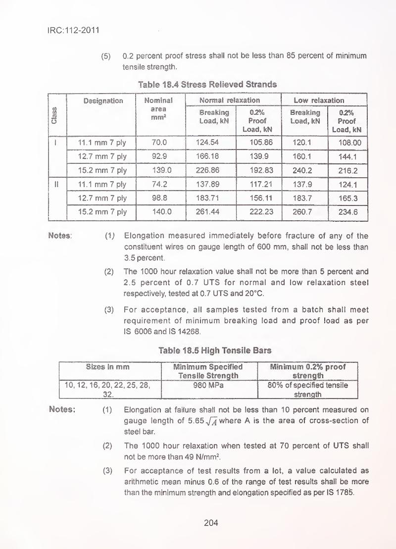
IRC:112-2011
(5) 0.2 percent proof stress shall not be less than 85 percent of minimum
tensile strength.
Table 18.4 Stress Relieved Strands
J
Designation Nominalarea
mm^
Normal relaxation Low relaxation
Breathing
Load, IcN
02%Proof
Load, kN
Breaking
Load, kN02%Proof
Load, kN
1 11.1 mm 7 ply 70.0 124.54 105.86 120.1 108.00
12.7 mm 7 ply 92.9 166.18 139.9 160.1 144.1
15.2 mm 7 ply 139.0 226.86 192.83 240.2 216.2
II 11.1 mm 7 ply 74.2 137.89 117.21 137.9 124.1
12.7 mm 7 ply 98.8 183.71 156.11 183.7 165.3
15.2 mm 7 ply 140.0 261.44 222.23 260.7 234.6
Notes: (1j Elongation measured immediately before fracture of any of the
constituent wires on gauge length of 600 mm, shall not be less than
3.5 percent.
(2) The 1000 hour relaxation value shall not be more than 5 percent and
2.5 percent of 0.7 UTS for normal and low relaxation steel
respectively, tested at 0.7 UTS and 20'C.
(3) For acceptance, ail samples tested from a batch shall meet
requirement of minimum breaking load and proof load as per
IS 6006 and IS 14268.
Table 18.5 High Tensile Bars
Sizes In mm Minimum Specified
Tensile Strength
Minimum 0.2% proofstrength
10,12.16, 20.22.25.28.
32.
980 MPa 80% of specified tensile
strength
Notes: (1) Elongation at failure shall not be less than 10 percent measured on
- gauge length of 5.65./^ where A is the area of cross-section of
steel bar.
(2) The 1000 hour relaxation when tested at 70 percent of UTS shall
not be more than 49 N/mm^.
(3) For acceptance of test results from a lot, a value calculated as
arithmetic mean minus 0.6 of the range of test results shall be more
than the minimum strength and elongation specified as per IS 1785.
204
IRC:11 2-2011
(4) 0.2 percent proof stress shall not be less than 85 percent of minimum
tensile strength.
18.3.3 Other properties
18.3.3.1 Ductility
The requirements of ductility at fracture are deemed to be satisfied by use of steel
having the minimum elongations specified in Clause 18.3.2.
The wires/strands shall pass the bendability test (reverse bending test) as specified in
relevant Indian Standards. ^
,
18.3.3.2 Tolerance on size/diameter'
The relevant Indian Standards specify the manufacturing tolerances on diameters/size
of various products, which remain valid for general acceptance of the material and for
qualifying the source of supply.
18.3.4 Coated wires/strands
The wires/strands conforming to Indian Standards can be provided with protective coatings,
like galvanising orepoxy coating, carried out in specialised manufacturing units. However,
ifthe technological processes affect any of the mechanical and physical properties, such
modified properties should be taken into account in design.
18.4 Material Ingredients of Concrete
The concrete shall be prepared by using ingredients given in this Clause.
18.4.1 Cement '
•
The cement shall be any of the following. The selected type should be appropriate for
the intended use.
Type
(a)
(b)
(c)
(d)
(e)
(f)
Ordinary Portland Cement 33 Grade conforming to
Ordinary Portland Cement 43 Grade conforming to
Ordinary Portland Cement 53 Grade conforming to
Rapid Hardening Portland Cement conforming to
Sulphate Resistant Portland Cement conforming to
Portland Pozzolana Cement conforming to
IS 269
IS8112
IS 12269
IS 8041
IS 12330
IS 1489
(Part-I)
205
IRC:112-2011
:. (g) Portland Blast Furnace Slag Cement conforming to IS 455
(h) Low Heat Portland Cement conforming to IS 1 2600
If any other cement conforming to other International Standards is used, it shall be
corresponding to one of the types listed above and shall meet the minimum specifications
of the Indian Standards.
18.4.2 Chemical admixtures.
To improve properties of fresh concrete such as workability, admixtures conforming to
IS 9103 may be used..
18.4.3 Mineral admixtures .. , •.
--
The following mineral admixtures may be used in concrete to improve its performance:
(a) Fly ash conforming to Grade-! of IS 3812-2003. The proportion
should not be less than 20 percent nor should exceed 35
percent of the total mass of Ordinary Portland Cement and fly-ash.
(b) Ground Granulated Blast-Furnace Slag (GGBS) conforming to
IS 12089. The proportion should not be less than 50 percent
nor should exceed 70 percent of total mass of Ordinary Portland
Cement and GGBS.
(c) Silica fume conforming to IS 15388. Silica fume should be very
fine, non-crystalline SiO^, obtained as a by-product of Silicon or
Ferro-Siiicon alloy industries.
18.4.4 Aggregates • '"
,..^
18.4.4.1 Genera!
All coarse and fine aggregates shall conform to IS 383 and shall be tested to conform to IS
2386 Parts I to VI 11. ,
,
1 8. 4. 4.2 Coarse and fine aggregates
(1) Coarse aggregates shall consist of clean, hard, strong, dense, non-
porous and durable pieces of crushed stone, crushed gravel, natural
gravel or a suitable combination thereof or other approved inert
material.
(2) The maximum size of the coarse aggregate may be as large as
possible within the limits specified, but in no case greater than (a) one
206
IRC:112-2011
quarter of the minimum thickness of member, (b) 1 0 mm less than
the minimum lateral clear distance between individual
reinforcements or (c) 1 0 mm less than the minimum clear cover to
any reinforcement.
(3) The preferred nominal size of aggregate is 20 mm for reinforced
concrete and prestressed concrete. However, larger sizes upto
40 mm may be permitted in special cases, when there is no restriction
to flow of concrete in a section.
For plain concrete, preferred nominal sizes may be between
20 mm and 40 mm. However, larger sizes may be permitted only in
,
special cases, subject to supplemental specifications andprecautions.
(4) Fine aggregates shall consist of hard, strong, durable clean particles
of natural sand, crushed stone or gravel or suitable combination of
natural sand and crushed stone or gravel.
(5) The coarse and fine aggregates shall not contain dust, lumps, soft
or flaky particles, mica and other deleterious materials in such
quantities as would reduce the strength or durability of concrete or
attack the reinforcement.
(6) Grading of aggregates shall be such as to produce a dense concrete
of the specified strength, which can be worked readily into position
without segregation and without the use of excessive water content.
18.4.6 . Water"
-
'
.-.
Water used for mixing and curing shall be clean and free from injurious amounts of oils,
acids, alkalis, salts, sugar, organic materials or other substances that may be deleterious
to concrete or steel.
(1) in case of doubt regarding development of strength, the suitability
of water for producing concrete shall be ascertained by the
compressive strength and initial setting time tests specified in (3) &
(4).
(2) The sample of water taken for testing shall represent the water
proposed to be used for concreting, due account being paid to
seasonal variation. The sample shall not receive any treatment
before testing other than that envisaged in the regular supply of
water proposed for use In concrete. The sample shall be stored in
a clean container previously rinsed out with similar water.
207
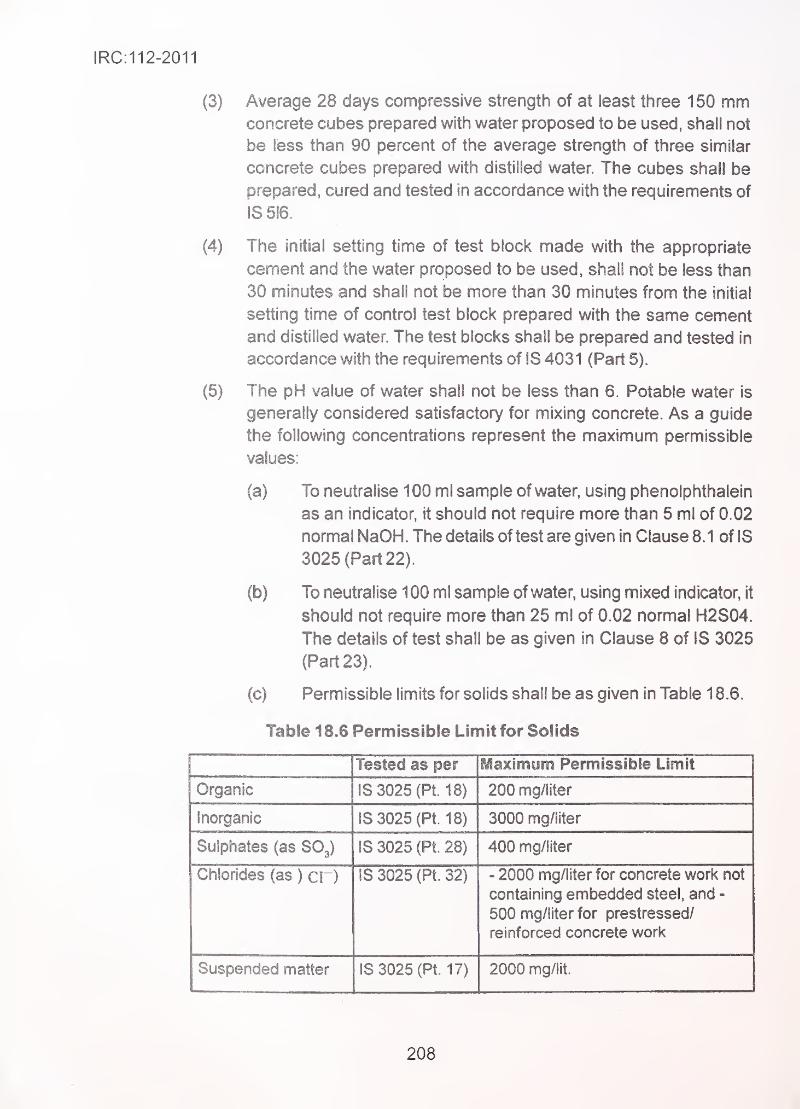
IRC:112-2011
(3) Average 28 days compressive strength of at least three 1 50 mmconcrete cubes prepared with water proposed to be used, shall not
be less than 90 percent of the average strength of three similar
concrete cubes prepared with distilled water. The cubes shall be
prepared, cured and tested in accordance with the requirements of
IS 516.
(4) The initial setting time of test block made with the appropriate
cement and the water proposed to be used, shall not be less than
I
30 minutes and shall not be more than 30 minutes from the initial
setting time of control test block prepared with the same cement
and distilled water. The test blocks shall be prepared and tested in
accordance with the requirements of IS 4031 (Part 5).
(5) The pH value of water shall not be less than 6. Potable water is
generally considered satisfactory for mixing concrete. As a guide
the following concentrations represent the maximum permissible
values:
(a) To neutralise 1 00 ml sample of water, using phenolphthalein
as an indicator, it should not require more than 5 ml of 0.02
nomnal NaOH. The details of test are given in Clause 8.1 of IS
3025 (Part 22).
(b) To neutralise 1 00 ml sample of water, using mixed indicator, it
should not require more than 25 ml of 0.02 normal H2S04.
The details of test shall be as given in Clause 8 of IS 3025
(Part 23).
(c) Permissible limits for solids shall be as given in Table 1 8.6.
Table 18.6 Permissible Limit for Solids
Tested as per Maximum Permissible Limit
Organic IS 3025 (Pt. 18) 200 mg/liter
Inorganic IS 3025 (Pt. 18) 3000 mg/liter
Sulphates (as SO3) IS 3025 (Pt. 28) 400 mg/liter
Chlorides (as ) cD IS 3025 (Pt. 32) - 2000 mg/liter for concrete work not
containing embedded steel, and -
500 mg/liter for prestressed/
reinforced concrete work
Suspended matter IS 3025 (Pt. 17) 2000 mg/lit.
208
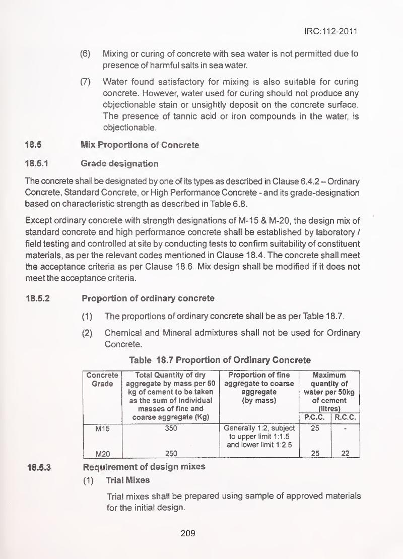
IRC:112-2011
(6) Mixing or curing of concrete with sea water is not permitted due to
presence of harmful salts in sea water.
(7) Water found satisfactory for mixing is also suitable for curing
concrete. However, water used for curing should not produce any
objectionable stain or unsightly deposit on the concrete surface.
The presence of tannic acid or iron compounds in the water, is
objectionable.
18,5 Mix Proportions of Concrete -.
18.5.1 Grade designation
The concrete shall be designated by one of its types as described in Clause 6.4.2 - Ordinary
Concrete, Standard Concrete, or High Performance Concrete - and its grade-designation
based on characteristic strength as described in Table 6.8.
Except ordinary concrete with strength designations of M-15 & M-20, the design mix of
standard concrete and high perfonnance concrete shall be established by laboratory /
field testing and controlled at site by conducting tests to confirm suitability of constituent
materials, as per the relevant codes mentioned in Clause 18.4. The concrete shall meet
the acceptance criteria as per Clause 18.6. Mix design shall be modified if it does not
meet the acceptance criteria.
18.5.2 Proportion of ordinary concrete
(1) The proportions of ordinary concrete shall be as per Table 18.7.
(2) Chemical and Mineral admixtures shall not be used for Ordinary
Concrete.
Table 18.7 Proportion of Ordinary Concrete
Concrete
GradeTotal Quantity of dry
aggregate by mass per 50
kg of cement to be taken
as the sum of individual
masses of fine and
Proportion of fmeaggregate to coarse
aggregate
(by mass)
Maximumquantity of
water per 50kgof cement
(litres)
coarse aggregate (Kg) P.C.C. R.C.C.
M15 350 Generally 1:2, subject
to upper limit 1:1.5
and lower limit 1:2.5
25
M20 250 25 22
18.5.3 Requirement of design mixes
(1) Trial Mixes
Trial mixes shall be prepared using sample of approved materials
for the initial design.
209
IRC:112-2011
Additional trial mixes and tests shall be carried out during production
in case any changes in the properties of fresh concrete and/or
strength of hardened concrete on the basis of early age tests, are
observed, so as to control and bring the quality of concrete within
acceptable limits. In case of any change in the source of materials,
or properties of materials, the design of mix shall be newly
established.
(2) Procedure for Design of Mix
Procedures as per any national code or any procedure established
by practice for arriving at the suitable mix design, can be followed.
Where earlier experience of concrete made from the selected
materials is available, the same can provide the basis for the start
of the mix design.
The target mean strength of concrete shall exceed the specified
characteristic strength by at least the margin (called current margin)
taken as 1 .645 times the standard deviation of sample test results
taken from at least 30 separate batches of concrete of nominally
similar proportions produced at site by the same plant under similar
supervision, over a period exceeding 5 days, but not exceeding
one month.
Where sufficient data as above to establish the standard deviation
is not available, the current margin for the initial mix design shall
be taken as 10 MPa, (i.e. standard deviation as 6 MPa) for normal
and uniform conditions of quality controls. This initial current margin
shall be used only until sufficient data are available to determine
the current margin as described above.
18.5.4 Sampling and testing
(1) General
(a) Samples from fresh concrete shall be taken as per IS 1199
and samples shall be made, cured and tested at specified
number of days in accordance with IS 516. The strength
parameters are based to 28 days strength. Tests at other age
shall be performed, if specified.
(b) Where automated batching plant is located away from the place
of use or concrete is supplied from Ready Mixed Concrete (RMC)
Plant, and the time gap between production and placement is
more than the initial setting time or where any ingredients are
210
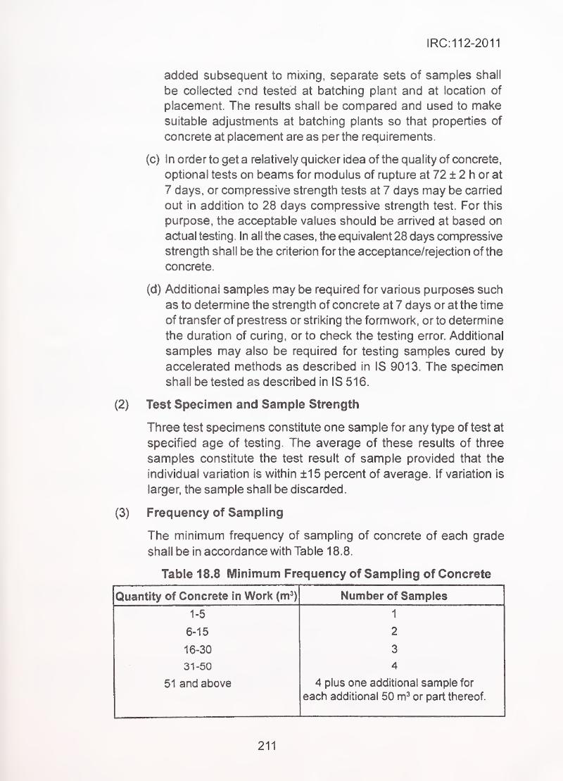
IRC:112-2011
added subsequent to mixing, separate sets of samples shall
be collected rnd tested at batching plant and at location of
placement. The results shall be compared and used to makesuitable adjustments at batching plants so that properties of
concrete at placement are as per the requirements.
(c) In order to get a relatively quicker idea of the quality of concrete,
optional tests on beams for modulus of rupture at 72 ± 2 h or at
7 days, or compressive strength tests at 7 days may be carried
out in addition to 28 days compressive strength test. For this
purpose, the acceptable values should be arhved at based on
actual testing. In ail the cases, the equivalent 28 days compressive
strength shall be the criterion for the acceptance/rejection of the
concrete.
(d) Additional samples may be required for various purposes such
as to determine the strength of concrete at 7 days or at the time
of transfer of prestress or striking the formwork, or to determine
the duration of curing, or to check the testing error. Additional
samples may also be required for testing samples cured by
accelerated methods as described in IS 9013. The specimen
shall be tested as described in IS 516.
(2) Test Specimen and Sample Strength
Three test specimens constitute one sample for any type of test at
specified age of testing. The average of these results of three
samples constitute the test result of sample provided that the
individual variation is within ±15 percent of average. If variation is
larger, the sample shall be discarded.
(3) Frequency of Sampling
The minimum frequency of sampling of concrete of each grade
shall be in accordance with Table 1 8.8.
Table 18.8 Minimum Frequency of Sampling of Concrete
Quantity of Concrete in Work (m^) Number of Samples
1-5 1
6-15 2
16-30 3
31-50 4
51 and above 4 plus one additional sample for
each additional 50 or part thereof.
211
IRC:112-2011
At least one sample shall be taken from each batch ofwork. For the purpose of acceptance
as per Table 18.8, quantity of concrete represented by a group of four consecutive samples
shall include all batches and single sample shall represent the batch from which It is taken.
Where concrete Is provided continuously at site from a batching plant or RMC plant, groups
of four consecutive samples, shall not have overlapping common samples. Irrespective of
other methods of controlling production used at the batching/RMC plant the requirements
of this Clause shall be met.
18.6 Acceptance Criteria
18.6.1 General
Acceptance or rejection of concrete is mostly based on compressive strength. However,
other properties ofthe concrete in fresh and hardened states including durability are also
important.
Apart from meeting the acceptance criteria given below, concrete is liable to be rejected if
it is porous or honey-combed, its placing has been interrupted without providing a proper
construction joint, the reinforcement has been displaced beyond the tolerances specified,
or construction tolerances have not been met. However, the hardened concrete may be
accepted after carrying out suitable remedial measures.
18.6.2 Compressive strength
When both the following conditions are met, the concrete shall be deemed to comply with
the specified compressive strength:
(a) The mean strength determined from any group of four
consecutive non-overlapping samples shall exceed the specified
characteristic compressive strength by3 MPa.
(b) Strength of any sample is not less than the specified
characteristic compressive strength minus 3 MPa.
Concrete of each grade shall be assessed separately.
Ifthe concrete is deemed not to comply as per the above criteria, the structural adequacy
of the bridge elements affected shall be investigated and any consequential action as
needed, shall be taken.
212
IRC:112-2011
18.6.3 Flexural strength
When both the following conditions are met, the concrete complies with the specified flexural
strength:
(a) The mean strength determined from any group of four
consecutive non-overlapping samples exceeds the specified
characteristic flexural strength by at least 0.3 MPa.
(b) The strength determined from any sample is not less than the
specified characteristic flexural strength minus 0.3 MPa.
Where minimum density of fresh concrete is specified, the mean of any four consecutive
non-overlapping samples shall not be less than the specified value and any individual
sample result shall not be less than 97.5 percent of the specified value.
Where minimum density of hardened concrete is specified, the mean ofany four consecutive
non-overlapping samples shall not be less than the specified value and any individual
sample result shall not be less than 97.5 percent of the specified value.
18.6.6 Chloride content
The chloride content in the concrete can be measured as described in IS 14959 -
Part I (for fresh concrete) or Part II (for hardened concrete). Alternatively it can be
calculated, in which case, the method of calculation shall be based upon the measured
chloride-ion contents of all constituents and the mix proportion of concrete. The chloride-
ion content so measured or calculated and expressed as the percentage of chloride-ion
by mass of cement, shall not exceed the value specified in Clause 14.3.2.3.
18.6.7 Durability of concrete
Unlike the tests on concrete described above, there is no specified test method for durability,
which can be completed within a reasonably short time. The requirement of long term
durability of concrete is 'deemed to be satisfied' by following the recommended provisions
in this Code for maximum water-cement ratio, minimum cement content, cover thickness,
type of cement and amounts of chlorides and sulphates in concrete etc. All these
recommendations taken together tend resulting concrete being dense, workable, and
placeable and having as low permeability as possible under the given situation.
When durability of concrete is the main reason for adopting high perfonnance concrete, or
18.6.4 Density of fresh concrete
18.6.5 Density of hardened concrete
213
IRC:112-2011
in other specific situations, Rapid Chloride Ion Permeability Test (RCPT) as perASTMC1202 shall be carried out. Suggested upper limits of values of RCPT for 56 days for
various exposure conditions (referTable 14.1) are:
(1) Extreme 800 Coulombs
(2) Very Sever 1200 Coulombs
(3) Severe 1500 Coulombs
Additional durability tests, such as Water Permeability test as per DIN 1 048 Part 5 or Initial
Surface Absorption test as per BS 1881 part 5 can also be specified. The permissible
values in such tests have to be specified taking into account the severity of the exposure
condition. The acceptance criteria shall be arrived at prior to testing.
18.7 Grouting
18.7.1 General
Grout is a homogenous mixture of cement and water. It may contain chemical admixtures
which modify the properties of grout in its fluid state. These recommendations cover the
cement grouting of post tensioned tendons of prestressed concrete members of bridges.
The purpose of grouting is to provide permanent protection to the post tensioned steel
against corrosion and to develop bond between the prestressing steel and the sunrounding
structural concrete. The grout ensures encasement of steel in an alkaline environment for
corrosion protection and by filling the duct space it prevents water collection and freezing.
A critical feature of grout is that it should remain pumpable for the time required to fully
inject the tendon.
18.7.2 Materials
(1) Water "
..
Only clean potable water free from impurities confomiing to Clause
1 8.4.5 shall be used. No sea or creek water is to be used at all.
(2) Cement
The same type of cement as used in construction of prestressed
elements, should be used for preparation of the grout. It should be
as fresh as possible and free from any lumps.
(3) Sand
It is not recommended to use sand for grouting of prestressing
tendons.
214
IRC:112-2011
(4) Admixtures
Acceptable admixtures conforming to IS 9103 may be used if tests
have shown that their use improves the properties of grout, i.e.
increasing fluidity, reducing bleeding, entraining air or expanding
the grout. Admixtures must not contain chlorides, nitrates, sulphides,
sulphites or any other products which are likely to damage the steel
or grout. When an expanding agent is used, the total unrestrained
expansion should not exceed 10 percent. Aluminium powder as
an expanding agent is not recommended as doubts exist about its
long term effects.
18.7.3 Use of grout colloidal mixer
It is essential that the grout is maintained in a homogenous state and of unifonn consistency
so that there is no separation of cement during the entire grouting process. It is, therefore,
necessary that the grout be continuously mixed in a colloidal mixer with a minimum speed
of 1000 RPM and travel of discharge not exceeding 15 m per second.
18.7.4 Properties of the grout
Before grouting, the properties of the grout mix should be tested. Tests should be
conducted for each job periodically.
(1) Water/cement Rratio
Water/cement ratio should be as low as possible, consistent with
workability. This ratio should not exceed 0.45.
(2) Deleterious Materials
No chloride, sulphates shall be separately added to the grout. The
constituent may contain chlorides/sulphates. However, its net effect
should not exceed the following limits in the grout:
- Chlorides (CI ) not more than 0. 1 percent by weight of cement.
- Sulphate (SO3) not more than 4 percent by weight of cement.
- Sulphide-ions (S2") not more than 0.01 percent by weight of
cement.
(3) Temperature
The temperature of the grout after accounting for the ambient
temperature of the structure, shall not exceed 25X.
215
IRC:112-2011
(4) Compressive Strength
The compressive strength of 1 00 mm cube of the grout shall not
be less than 17 MPa at 7 days. Cubes shall be cured in a moist
atmosphere for the first 24 hours and subsequently in water. Thesetests shall be conducted in advance to ascertain the suitability of
the grout mix.
(5) Setting Time
Initial setting time of grout shall be more than three hours and less
than 1 2 hours. The final setting time shall not be less than 24 hours.
(6) Bleeding
Bleeding is the separation of free water from the grout
mix. It includes the filtering effect of strands where the cavities
between the wires constituting the strand, block cement particles and
permit water under pressure to move ahead of the grout in the
direction of general flow of grout. The bleeding shall be sufficiently
low to prevent excessive segregation and sediment of the grout
material. The bleeding shall not exceed 0.3 percent of volume of the
initial volume of grout after three hours kept at rest.
(7) Volume Change
The volume change of grout kept at rest for 24 hours and tested as
per ASTM C1090 shall be within the range of -0.5 percent and
5 0 percent of the original volume.
(8) Fluidity
Fluidity is tested as perASTM 0939 standard using standard flow
; cone.
Note: The fluidity of grout changes from time of mixing to time of setting
in the ducts. The requirement given above are for general
guidance and may be modified as per the specific application,
depending upon the total temperature, length oftendons, head of
pumping, requirement ofsimultaneous grouting of closely spaced
tendons etc. provided that other specifications and functions are
satisfied.
18.8 Quality Control and Workmanship
18.8.1 General
This Clause covers the requirements of properworkmanship in all operations of construction
of concrete structures and related quality assurance and quality control measures, so that
the structure is built as designed and the intended performance over the design service
216

IRC:112-2011
life is achieved. Concrete is made with ingredients with inherent variability. The operations
of production, placement, compaction and curing of concrete under site conditions can
also exhibit variability. In order that concrete is obtained with reasonable amount of
consistency in its characteristics, the properties of ingredients and the resultant concrete
should be monitored diligently as per an appropriate plan of testing and all site operations
should be carried out with adequate proficiency, as detailed in this Section. A Quality
Assurance (OA) Plan should be in position to ensure that the construction results in
satisfactory strength, serviceability and long term durability which will lower the overall life-
cycle cost of the structure.
18.8.2 Quality assurance measures
Quality assurance in construction activity relates to proper design, use of appropriate
materials and components to be supplied by the producers, proper workmanship in the
execution ofworks and proper care during the use ofstmcture, including periodic inspection
and timely maintenance and repair by the owner.
Quality assurance measures are both technical and organizational. The Quality
Assurance Plan shall identify the key elements necessary to provide fitness of the
structure and the means by which they are to be provided and measured with the
overall purpose to provide confidence that the realized project will work satisfactorily in
service, fulfilling intended needs. Quality control and quality assurance would also involve
ensuring quality of both the inputs as well as the outputs. Inputs are in the form of
materials of construction: workmanship; and the related plant, machinery and equipment;
resulting in the output in the form of final structure.
Each party involved in the realization of a project should establish and implement a
QualityAssurance Plan for its role in the project. Suppliers and sub-contractors' activities
shall be covered in the plan. The individual Quality Assurance Plans shall fit into the
overall QualityAssurance Plan ofthe project and shall define the tasks and responsibilities
of ail persons involved, adequate control and checking procedures, and the organization
and maintaining of adequate documentation of the construction process and its results.
Such documentation shall be in accordance with IRC Publication IRC:SP:47-1988
"Guidelines on Quality Systems for Road Bridges' Plain, Reinforced Prestressed and
Composite Concrete".
18.8.3 Production of concrete
(1) Storage of Materials
All efforts shall be made to store the materials in proper places to
prevent their deterioration and any intrusion of foreign matters, so
as to ensure their satisfactory quality and fitness for the wori^. The
217
space shall permit easy storage, inspection, remova! and
re-storage of materials. All such materials, even though stored in
approved manner, shall be subjected to inspection and acceptance
test prior to use, whenever considered necessary.
Batching
In batching concrete: • "
• The quantity of cement, aggregate and mineral admixtures, if
used, shall be determined by mass.
• Chemical admixture, if solid, shall be determined by mass.
• Liquid admixture may be measured in volume or mass, and
• Water shall be weighed or measured by volume in a calibrated
tank."
The concrete shall be soureed from on-site or off-site batching and
mixing plants, or from approved ready-mixed concrete plants,
preferably having quality certification.
Except where supply of properly graded aggregate of uniform quality
can be maintained over a period of work, the grading of aggregate
should be controlled by obtaining the coarse aggregate in different
sizes and blending them in the right proportions when required,
the different sizes being stocked in separate stock piles. The
material should be stock piled several hours, preferably a day
before use. The grading of coarse and fine aggregate should be
checked as frequently as possible to ensure that the specified
grading is maintained.
The accuracy of the measuring equipment shall be within ±3 percent
of the quantity of cement, aggregate, admixtures and water being
measured. All measuring equipment shall be maintained In a clean
and serviceable condition. Their accuracy shall be checked over
the range in use, when set up at site and maintained thereafter.
It is important to maintain the water-cement ratio constant at its
correct value. To this end, determination of moisture contents In
both fine and coarse aggregates shall be made as frequently as
possible, being determined according to weather conditions. The
amount of the added water shall be adjusted to compensate for
any observed variations in the moisture contents. To allow for the
variation in mass of aggregate due to variation in their moisture
218
IRC:112-2011
content, suitable adjustments in the masses of aggregates shall
also be made. Accurate control shall be kept on the quantity of
mixing water, which when specified, shall not be changed without
approval.
(3) Mixing
All concrete shall be machine-mixed. In order to ensure uniformity
and good quality of concrete, the ingredients shall be mixed in a
power driven batch mixer with hopper and suitable weigh batching
arrangement or in a central mix plant. The concrete shall be mixed
until it is of even colour, cohesive and of uniform consistency
throughout. When mineral admixtures are added at the mixing
stage, their thorough and uniform blending with the cement shall
be ensured, if necessary, by longer mixing time. In general, the
mixing time shall be at least 2 minutes after all the ingredients are
in the mixer. For other types of more efficient mixers, manufacturer's
recommendations should be followed. The addition of water after
the completion of the initial mixing operation, shall not be pemnitted.
Transportation, placing, compaction and curing
(1) Transporting Concrete
Mixed concrete shall be transported from the place of mixing to the
place of final placement as early as practicable, by methods which
will prevent the segregation or loss of the ingredients.
Concrete may be transported by transit mixers or properly designed
buckets or by pumping. Transit mixer or other hauling equipment
when used, should be equipped with means of discharging the
concrete without segregation. During hot or cold weather, concrete
shall be transported in deep containers. Other suitable methods to
reduce the loss ofwater by evaporation in hot weather, and heat loss
in cold weather, may also be adopted.
When concrete is conveyed by chute, the plant shall be of such
size and design as to ensure practically continuous flow in the chute.
The slope of the chute shall be such as to allow the concrete to
flow freely and without segregation of the ingredients. The delivery
end of the chute shall be as close as possible to the point of deposit.
The chute shall be thoroughly flushed with water before and after
each working period and the water used for this purpose shall be
discharged outside the formwork.
219
In case of concrete is to be transported by pumping, the fresh
concrete should have adequate fluidity and cohesiveness to be
pumpable. Proper concrete mix proportioning and initial trials should
be canied out to ensure this. The conduit shall be primed by pumping
abatch of mortar through the line to lubricate it. Once the pumping is
started, it shall not be interrupted, as concrete standing idle in the
line is liable to cause a plug. The operator shall ensure that someconcrete is always there in the pump's receiving hopper during
operation. The lines shall always be maintained clean and free of
dents.
Placing and Compacting Concrete
Concrete shall be placed as nearly as practicable in its final
position to avoid rehandling. Methods of placing should be such
as to preclude segregation. Care should be taken to avoid
displacement of reinforcement or movement of formwork. To
achieve this, concrete should be lowered vertically into the fomns
and horizontal movement of concrete inside the fomis should, as
far as practicable, be minimised.
Concrete shall be placed and compacted before its initial setting
so that it is amenable to compaction by vibration. The workability
of concrete at the time of placement shall be adequate for the
compaction equipment to be used. If there is considerable time
gap between mixing and placing of concrete, as in the case of
ready mixed concrete plants or off-site batching and mixing plants,
concrete mix shall be designed to have appropriately higher
workability at the time of discharge from the mixer, in order to
compensate the loss of workability during transit. This is generally
achieved by use of suitable chemical admixtures. Keeping these
considerations in view, the general requirement for ready mixed
concrete plants or off-site batching and mixing plants, is that concrete
shall be discharged from the truck mixer within two hours of the
time of loading.A longer period may be permitted if suitable retarding
admixtures are used. In case of on-site mixing, fresh concrete shall
preferably be placed and compacted within 30 minutes of mixing.
In wall forms, drop chutes attached to hoppers at the top should
preferably be used to lower concrete to the bottom of the form. As
a general guidance, the permissible free fall of concrete may not
exceed 1 .5 m and under no circumstances; shall it be more than
2 m.
220
IRC:112-2011
When free fall of larger height is involved, self compacting concrete
having adequate fluidity, cohesiveness and viscosity shall be used.
Self compacting concrete completely fills every corner
of the formwork by its own weight without segregation, whilst
maintaining uniformity. No compaction by vibration is required.
When concrete is to be deposited by means of tremie, the lower
end of the vertical pipe shall always be inserted sufficiently deepinto the concrete which has been placed previously but has not
set. The top section of the tremie shall be a hopper large enough
to hold one entire batch of the mix or the entire contents of the
transporting bucket, if any. The tremie pipe shall be large enoughto allow a free flow of concrete and strong enough to withstand the
external pressure of the water in which it is suspended, whenconcrete is deposited under water. It will be necessary to raise the
tremie slowly in order to cause a uniform flow of the concrete, but
the tremie shall not be emptied allowing water to enter the pipe. At all
times after the placing of concrete is started and until all the concrete
is placed, the lower end of the tremie pipe shall be below the top
surface of the plastic concrete.
Concrete shall be thoroughly compacted during the operation of
placing and carefully worked around the reinforcement, around
embedded fixtures and into the corners of the forni work. To achieve
proper compaction vibrators may be used. The vibrator can be
internal or external type and depending upon the shape and size
of the member, both types may be used individually or together.
When internal vibrators are used, they shall be inserted vertically
to the full depth of the layer being placed and ordinarily shall
penetrate the layer below for a few centimetres. The vibrator should
be kept in place until air bubbles cease escaping from the surface
and then withdrawn slowly to ensure that no hole is left in the
concrete, care being taken to see that it remains in continuous
operation while being withdrawn. Internal vibrators shall be
inserted in an orderly manner and the distance between insertions
should be about VA times the radius of the area visibly affected by
vibration. Internal vibrators should not be used for spreading the
concrete.
Construction Joints
Concreting shall be carried out continuously up to construction joints,
the position and arrangement of which shall be pre-determined by
the designer. Joints should be positioned where they are readily
accessible for preparation and concreting. Construction joints should
221
be positioned to minimise the effects of the discontinuity on the
durability, stmctural integrity and appearance of the structure. Asfar as possible, joints should be provided in non-aggressive zones,
but if joints in aggressive zones can not be avoided, they should besealed. Joints should be located away from regions of maximumstress caused by loading; particularly where shear and bondstresses are high.
^
Joints should be either vertical or horizontal. For a vertical
construction joint, the lifts of concrete shall finish level or at right
angles to the axis of the member. Concreting shall be continued
right up to the joint.
Before resuming work at a construction joint when concrete has
not yet fully hardened, all laitance shall be removed thoroughly.
The surface should be roughened, care being taken to avoid
dislodgement of coarse aggregates. Concrete may be brushed with
a stiff brush soon after casting, while the concrete has only slightly
stiffened. If the concrete has partially hardened, it may be treated
by wire brushing or with a high pressure water jet, followed by drying
with an air jet, immediately before the new concrete is placed. Fully
hardened concrete shall be treated with mechanical hand tools or
grit blasting, taking care not to split or crack the aggregates.
The practice of first placing a layer of mortar or grout whenconcreting joints is not recommended. The old surface should be
soaked with water, without leaving puddles, just before
starting concreting. The new concrete shall be thoroughly
compacted against it.
Where there is likely to be a delay before placing the next concrete
lift, protruding reinforcement shall be protected. In all cases, where
construction joints are made, the joint surface shall not be
contaminated with release agents, dust, or sprayed curing
membrane and reinforcement shall be fimrily fixed in position at the
correct cover.
The sequence of concreting, striking of forms and positioning of
construction joints for every individual stmcture shall be decided, well
in advance of the commencement of work.
Curing and Protection of Concrete
The concrete shall be kept constantly wet for a minimum period of
14 (fourteen) days by ponding or covering with a layer of
wet (but not dripping) sacking, canvas, hessian or similar
absorbent material. Water should be applied on unformed surfaces
222
IRC:112-2011
as soon as It can be done without marring the surface and on formed
surfaces immediately after the fomns are stripped.
Liquid membrane-forming curing compounds conforming to
ASTM C 309, may be used in lieu of moist curing after approval.
The curing efficiency shall be tested as per ASTM C 156. Such
compounds shall be applied to all exposed surfaces of the concrete
as soon as possible after the concrete has set, but not dried out.
The membrane formed shall be stripped off afterwards.
Impermeable membranes, such as sheet materials for curing
. concrete conforming to ASTM C 171, or polyethylene sheeting
covering closely the concrete surface, may also be used to provide
effective barrier against evaporation.
Steam curing under atmospheric pressure is adopted to develop
high early strength of concrete, so that concrete members can beremoved from the formwork and handled as early as possible. This
is particuiariy suitable for precast concrete members. Steam curing
is applied in enclosures or tunnels through which concrete membersare transported on a conveyor system; alternatively, portable
enclosures or plastic covers are placed over precast members.Steam is supplied to the enclosures. Various elements of the steam
curing cycle, e.g. the delay in commencement of heating (i.e.
extending pre-steaming period), the rate of increase oftemperature,
the level and time of constant temperature, and the rate of decrease
of temperature, shall receive careful consideration. As a general
guidance, the pre-steaming period should be about one to three
hours, the rate of increase or decrease of temperature should not
exceed 10 to 20°C per hour and the maximum temperature of curing
can be about 70°C.The ideal steam curing cycle in a particular
situation, is govemed by the concrete mix proportions and type
of cementitious materials and the strength required at the end of
steam curing period, and shall be decided by prior trials. Steamcuring of concrete shall be followed by water curing for at least
seven days.
After placing and during the first stages of hardening, concrete
shall be protected from harmful effects of sunrays, drying winds,
cold, running water, shocks, vibrations, traffic including construction
traffic etc.
Concreting in extreme weather
(1 ) Concreting in Hot Weather
Special problems are encountered in the production, placement and
223
curing of concrete In hot weather. The climatic factors affecting
concrete in hotweather are high ambient temperature, reduced relative
humidity, high wind velocity and combination thereof. High
temperatures result in rapid hydration of cement, increased
evaporation of mixing water, greater mixing water demand, rapid loss
of workability and large volume changes resulting in cracks.
The temperature of concrete at the time of placement should be as
low as possible, but in no case more than 30°C. For high
performance concrete, the temperature at the time of placement
shall not exceed 25°C. If concreting has to be done in hot weather
at ambient temperatures exceeding these limits of concrete
temperature, steps shall be taken to sufficiently lower the temperature
of ingredients of the concrete below the ambient. The contribution of
each ingredient to the temperature of concrete is a function of the
temperature, specific heat and quantity of that ingredient.
Aggregates and mixing water exert the most pronounced effects
on the temperature of concrete. Thus, in hot weather, all available
means shall be used for maintaining these materials at as low
temperature as practicable, such as;
• Use of chilled mixing water
• Use of crushed ice or flaked as a part of mixing water.
• Shading stockpiles of aggregates from direct rays of Sun.
• Sprinkling stockpiles of coarse aggregate with water and
keeping them moist.
• Limiting temperature of cement to be preferably not in excess
of 30°C at the time of use.
Period between mixing of concrete and placing shall be as short as
possible. Immediately after compaction and surface finish, concrete
shall be protected from evaporation of moisture, without letting
ingress of external water, by means of wet (not dripping) gunny
bags, hessian etc. Once the concrete has attained some degree of
hardening (approximately 12 hours after mixing), moist curing shall
be commenced and satisfactorily continued throughout the requisite
period.
Concreting in Cold Weather
Effects of cold weather on concrete, in absence of special
precautions, include;
® Delayed setting and hardening, slower rate of gain of strength.
224
IRC:112-2011
• irreparable loss of strength and durability, if freezing of concrete
takes place at early ages, when it is still in plastic state. Even
one cycle of freezing of concrete during the prehardening period
may lower the compressive strength by 30 to 50 percent,
• Disruptive effects of freezing of pore water make hardened
concrete vulnerable to repeated cycles of freezing and thawing
,
resulting in loss of compressive strength and modulus of
elasticity.
• Stresses due to temperature differential within the concrete
member at the time of removal of form insulations, may promote
cracking.
When depositing concrete at or near freezing temperature,
precautions shall be taken to ensure that the concrete shall have a
temperature of at least 5°C at the time of placing. When necessary,
concrete ingredients shall be heated before mixing, but cement
shall not be heated artificially other than by the heat transmitted to
it from other ingredients of the concrete. In general, heating of only
the mixing water to about 65°C may suffice for this purpose.
The temperature of the concrete shall be maintained above freezing
temperature (preferably above 2*C) until it has thoroughly hardened.
This may be achieved with the help of proper insulating methods
before the protection is removed.
Use of air-entraining admixtures conforming to IS 9103 increases
the resistance of hardened concrete to freezing and thawing. To
counter slower setting of concrete, non chloride-bearing
accelerators can be used after approval. However, accelerators
containing chloride shall not be used.
No frozen material or materials containing ice shall be used. Ail
concrete damaged by frost shall be removed.
Steel reinforcement
(1) Bending
Reinforcement shall not be bent or straightened in a manner that
will injure the material. All reinforcement shall be bent cold:
Mechanised bending or prefabricated reinforcement shall be
preferred. Bar bending schedules shall be prepared for all
reinforcement work.
225

IRC:112-2011
(2) Placing
All reinforcement shall be placed and maintained in positions shownon the drawings by providing proper cover blocks, spacers,
supporting bars etc. High strength mortar or concrete of the samegrade with smaller size aggregate shall be used for cover blocks.
To ensure adequate cover, use of manufactured chairs is
recommended.
(3) Splicing and Lapping
Splicing and lapping shall be in positions conforming to the drawings
and for this purpose, all reinforcing bars shall be to the full lengths
indicated thereon. However, suitable adjustment in the locations of
the splices to accommodate the available lengths of bars, can bemade with prior approval. In all cases of such adjustment, the
requirements of lap length and other stipulations, as per
Sections 1 5 and 1 6 shall be compiled with.
(4) Substitution of Bar Sizes
In order to accommodate the available size of bars, use of bar
sizes other than those shown on the drawings may be permitted
with prior approval. In case of such substitution, the reinforcement
actually used shall have an area equivalent to the original or slightly
in excess thereof, provided further that the various stipulations of
this Code are not violated by such substitution. The requirements
with regard to bond stress, limitations of bar sizes, spacing of bars,
cover, etc., shall be specially looked into.
18.8.7 Falsework
For design, fabrication, and erection offalsewori<, IRC:87 "Guidelines for the Design and
Erection of Falsework for Road Bridges" shall be followed.
The formwori^ should be robust and strong and the joints should be leak proof. Form release
agents of approved quality shall be used. The staging, scaffolding and shuttering are
required to be property designed so that their erection as well as striking can be conveniently
done. The design should also ensure that at the time of striking, the concrete does not get
disturbed and the forms are conveniently removed. Staging shall be of steel pipes or steel
sections.
Where centering trusses or launching trusses are adopted for casting of superstructure,
the joints of the centering or launching arrangement, whether welded, riveted or bolted,
shall be thoroughly checked and various members of the centering trusses shall be
examined for proper alignment and unintended deformation before proceeding with the
concreting. Launching trusses and travelling forms shall be load tested.
226
IRC:112-2011
The locations where fixing of reinforcement and placing of concrete are being done, shall
be accessible to the inspecting officers at all stages of construction.
Fomns shall not be released until the concrete has achieved strength of at least twice the
stress to which the concrete may be subjected at the time of removal offonnwork. 1n absence
of tests, generally, the striking period may be as specified in !RC:87.
18.8.8 Inspection and testing of structures
(1) Inspection
To ensure proper performance, it is necessary that each step in
concreting which will be covered by the next step is inspected as
the work proceeds. Immediately after stripping the formwork, all
concrete shall be carefully inspected and any defective work or
small defects shall be either removed or made good before concrete
has thoroughly hardened. Concrete members shall be inspected
within 15 days for occurrence of cracks due to shrinkage,
temperature, local restraint, undue deflection and deformation.
(2) Testing of Concrete in Structures
In case of doubt regarding the grade of concrete in the structure, either
due to poorworkmanship or based on results of cube strength tests,
compressive strength tests of concrete shall be carried out by core
tests and/or non-destructive tests.
(3) Core Test
The points from which core samples are to be taken and the number
of core samples required shall be decided so as to be representative
of the whole of concrete concerned, in no case, however, shall
fewer than three cores be tested. Cores shall be prepared and
tested as described in IS 516.
Concrete in the member represented by a core test shall be
considered acceptable, if the average equivalent cube strength of
the cores is equal to at least 85 percent of the characteristic strength
of the grade of concrete specified for the corresponding age and
no individual core has strength less than 75 percent.
Core tests may also be required for other purposes like repair,
retrofitting and strengthening of structure where requirement of
strength could differ.
(4) Non-Destructive Tests
Nondestructive tests are used to obtain estimation of the properties
of concrete in the structure.
227
IRC:112-2011
The methods adopted include ultrasonic pulse velocity
|!S:13311(Part 1)| and rebound hammer [IS 13311 (Part 2)], probe
penetration (ASTM C 803), pullout (ASTM C 900) and maturity
(ASTM C 1074). Non-destructive tests provide alternatives to
core tests for estimating the strength of concrete in a structure, or
can supplement the data obtained from a limited number of core
specimens tested. These methods are based on measuring a
concrete property that bears some relationship to strength. Theaccuracy of these methods is determined by the degree of
correlation between strength and quality of the concrete and the
parameter measured by the non-destructive tests.
Any of these methods may be adopted, in which case the
acceptance criteria shall be agreed upon prior to testing.
18.8.9 Load tests of structures
(1) Load Test for Flexural Member
In case the core test results do not satisfy the requirement in
Clause 18.8.8 (4) or where such tests have not been done, load
test may be carried out if specifically desired. Load test should be
carried out as soon as possible after expiry of 28 days from time of
placing of concrete. Procedure as per IRC publication SP:51
'Guidelines for Load Testing of Bridges' may be adopted
.
(2) Members Other than Flexural Members
Members other than flexural members should be preferably
investigated by analysis.
228
IRC:112-2011
ANNEXURE A-1
ACTIONS, DESIGN SITUATIONS ANDCOMBINATION OF ACTIONS
A1-1 General
Section 5.0 "Basis of Design" describes the approach adopted for taking into consideration
various limit states, which shall not be exceeded by the bridge structure and its elements,
when subjected to combined effect of actions in various design situations. The values of
actions and partial factors to be used in different combinations for verification of design by
Limit State Method are given in IRC:6. Annexure-B, Table-1 of IRC:6 gives loads and load
combinations for verification of design by working load/allowable stress (WUAS) method.
The description of actions, their classification, nomenclature of design situations and
combination for verifying different limit states as applicable to concrete bridges, are
explained in thisAnnexure. The terms loads and force (arising out of friction, buoyancy etc)
are also used to represent 'Actions' in IRC:6, and in the description below.
A1-2 Classification ofAction
The description of actions and their notations given as per IRC:6, unless othen/vise stated.
(1) PermanentActions - G
(a) PermanentAction
(i) Self Weight/Dead Load
Self-weight of structure due to gravity.
(ii) Backfiil Weight
To be treated as D.L. when present. (Not separately defined
in IRC:6 for WL/AS method).
(iii) Earth Pressure: (F^p
)
In IRC:6, the increased earth pressure due to live load
surcharge considered is included by convention in F^p, For
Limit State Method the surcharge due to live load needs to be
taken as a variable load together with other live loads. (For
WL/AS method of design, its effect is evaluated in
combination with earth pressure F^p .)
229
(iv) Prestressing Force: (P)
In analysis of structure P is considered as a force acting on
concrete elements which has time dependant variation, and also
superior (i.e. higher estimate) and inferior (i.e. lower
estimate) values.
(v) Secondary Effects (F )
Such as creep, shrinkage and settlemefst '
Note: Second order effects arising from the deformed geometry are not
considered as secondary effects. These are considered for
verification of Ultimate Limit State of Deformation only.
(b)Variable Gravity Loads Treated as Permanent Loads
(1) Super Imposed Dead Load
Loads from hand rail, crash barrier, road furniture, footpath and
actual or provisional loads from services, etc.
(ii) Surfacing and Wearing Coat
In Limit State Method superior and inferior values may be used,
which should account for re-surfacing, with or without removing
existing coat, and possibility of change in type of surfacing.
(iii) Snow Load
Snow loads, if present, are treated in the same way as Dead
Load depending on the depth of snow on superstructure. The
design value of live load is modified depending on the restrictions
on operation of vehicular loads which give rise to different design
situations.
Quasi-Permanent Loads
There are variable loads which act for a major part ofthe structures
design life. By convention, loads acting for more than 50% of the
design life are called quasi-pemianent. In load combinations, they
are treated as variable loads with different values depending on
the action effects under evaluation. Temperature load is an
example, where it has a permanent component (casting
temperature), semi-permanent component (seasonal variation
from casting temperature) and varying component (daily variation
from seasonal temperature).
230
IRC:112-2011
Variable Actions - Q
(a) Vehicular
(i) Vehicular live load (Q)
Load due to gravity
(ii) Impact factor due to vehicular gravity load (QJ
A factor for converting dynamic increment of gravity load, dueto vehicle travelling at high speed on uneven surface ofwearing
coat, to equivalent static load.
(iii) Longitudinal forces
Caused by tractive effort of vehicles (F) or by braking
(F) and / or
Longitudinal force from bearings due to their type andconfiguration (F^).
(iv) Centrifugal force of vehicles travelling at high speed along a
curved track F,.
(v) Pedestrian Load/Foot Path Load
(vi) Earth Pressure Surcharge Effect due to Live Load (F^
(b) Loads of Environmental Origin
(i) Temperature effects due to restraints to free structural
deformation {FJ (excluding restraints due to frictional
resistance at bearings).
(ii) Effect of thennal gradient in the structure.
(iii) Wind Load (W)
Normally used as static load acting on bridge elements. For
wind sensitive structure or elements of structure dynamic
analysis and dynamic wind force is stipulated.
(c) Hydraulic Actions
These are variable loads, grouped together as sub-set ofvariable
loads and their significant effect in bridge design.
(i) Buoyancy effect (G^)
(ii) Water current forces (FJIncluding both drag and lift effects.
(iii)Wave Pressures (F )
231
IRC:112-2011
(3) Accidental Actions
Accidentai loads are those loads whose occurrence or frequency
cannot be predicted, and originate from unintended or undesirable
situations.
(a) impact of external bodies
(i) Vehicle collision on eiements of bridge structure (F).
(ii) Barge impact or impact due to floating bodies in water current.
(iii) Vehicular Impact on Crash Barriers. /
(b) Seismic IHazards
Seismic situations considered in the design are rare events [even
more rare than type 3(a)] having return period of the order of few
hundred years. They produce following types of loads.
(i) Inertial loads due to self-mass generated in bridge structure
by ground acceleration.
(ii) Inertial loads due to mass of vehicular live load.
(ill) Hydrodynamic forces generated on parts of bridge submerged
underwater.
(iv) Increased earth pressures.
(v) Effects of liquefaction of soils.
A1-3 Design Situation and Load Combination
Various actions defined in Clause A1 -2, act on the bridge structure at different time and in
different combinations. The magnitudes of the loads also differ from time to time. Thus the
loading conditions to which bridge structure is exposed are extremely large. In practice the
verification that the limit states are not exceeded is carried out for a limited number of
combinations, each ofwhich represents likely condition of bridge loading during its design
service life. The load combinations and the partial factors of loads to be considered in that
combination are defined in IRC:6-201 0. Basically, the following four design situations are
considered, depending on the duration of the load and the frequency of occurrence of load
combinations.
Persistent Design Situation (Basic Load Combinations)
It is the design situation that is relevant during a period of the same order as the design
working life of the structure. Generally it refers to conditions of normal use.
This includes permanent and quasi-permanent loads as well as variable loads like live
load, wind, hydraulic loads like water current buoyancy etc.
232
IRC:112-2011
Transient Design Situation
It is the design situation that is relevant during a pericxj much shorter than the design working
life of the structure but which has a high probability of occurrence
A transient design situation refers to temporary conditions of the structure, of use, or
exposure, such as those arising during construction orwhen restrictions are put on its use.
Accidental Design Situation
It is the design situation involving exceptional conditions of the structure or its exposure,
including fire, explosion, impact or local failure.
For concrete bridge structures, vehicle impact load is usually considered. The fire hazard
or explosion pressures, if specified, (e.g. as in case of material storage or human occupancy
below city flyovers) shall be based on the Indian Standards specifying fire resistance (as
per IS 456, IS 1641 and IS 1642) and blast resistance (as per IS 4991).
Seismic Design Situation '
'
/.
It is the design situation involving exceptional conditions of the structure when subjected to
a seismic event.
Generally, it is not economical to design bridge structure to remain within elastic limits
when subjected to 'Design Basis Earthquake' which is defined in IRC:6-2010. Parts of the
bridge structure are permitted to suffer damage during the design event. At higher level of
seismic event, the bridge elements are expected to suffer large but repairable damagewithout failure or collapse. Presently, IRC-6 is specifying force-based design methods,
which are deemed to achieve the aim of satisfactory performance.
Since the structural behaviour of the bridge under seismic conditions is completely different
(i.e. non-elastic response is considered) from the response to other loads (which are
essentially in elastic range), the seismic situations are separately treated.
A1-4 Limit States to be Considered
(1) Limit States of Strength (ULS)
Three limit states are checked:
(i) Stability of overall structure or its elements,
(ii) Failure of members or the whole structure by buckling of its
elements,
233
(iii) Failure of member at its critically loaded section under action of
axial force, bending moment, shear, and torsion.
Limit States of Serviceability (SLS) •
.
.
Following limit states of serviceability are covered in this Code:
(i) Limit state of stresses
(ii) Limit state of deformation (deflection)
(iii) Limit state of crack width
Other limit states such as limit state of vibration and limit state of
fatigue may be important for some bridge structures. Specialist
literature or international standards may be referred for the same.
Different serviceability limit states are governed by different sets of
load combinations. The following sets of load combinations are
defined in Section 12.
(a) Rare combinations (also called Characteristic Combination
or Infrequent Combination)
in these situations bridge element, are subjected to maximumdesign loads leading to maximum stress levels.
These basic combinations are used for checking 'limit state of
maximum stress levels' in bridge elements.
(b) Frequent Combinations
• These represents design situation that occurs repeatedly in
service.
The maximum allowable deflections, crack width in prestressed
elements with bonded tendons (and vibration where specified)
are checked for the frequently occuning situation.
(c) Quasi-Permanent Combinations
These combinations are used to consider long temn action effects.
Crack widths in reinforced concrete elements and
prestressed elements with unbonded tendons where durability is
affected and effects of settlement, creep etc., caused by
permanent or more or less pemnanent actions listed in A-1 .2(1 ),
are evaluated with quasi-permanent combinations.
234
IRC:112-2011
ANNEXURE A-2
ADDITIONAL INFORR^ATION AND DATA ABOUT PROPERTIES OFCONCRETE AND STEEL
A2J General
Section 6 gives values of various design properties. The co-relations on which these are
based are given in the following Sub-sections. Also, the expressions for creep and
shrinkage for different types of cements and in different conditions of relative humidity, are
given. Effect of high temperature curing, and multi-axial stresses is indicated. High
temperature curing also increases the rate of relaxation loss of steel in pre-tensioned pre-
cast members. Method of calculating the same is given.
An informative Sub-section is added about partial material factor for concrete, and use of
cores taken for measuring in-situ strength of concrete structures. The test results of cores
taken from existing structure are also used for retrofitting of old bridges by using probable
equivalent design cube strength j^.^, few observations on the co-relation between the two
are given for guidance of designers. .
For more detailed information on these and various other properties of concrete which
may be needed for special applications, while stilt using the general principles ofthis Code
specialist literature may be refen-ed.
A2.2 Co-relation between Compressive Cube Strength and OtherConcrete Properties
Table 6.5 gives directly the design properties of concrete in terms of its 28 days
compressive (cube) strength. The values are based on the following co-reiationships,
which are experimentally established. However, the scatter in values is larger than the
scatter in cube strengths, since co-relationship is not exact, but is a best fit to actual
data.
(1) fern= fck + 10, fen, and/cA in IvlPa ' Eq.A2-1
(2) (i) - 0.259 (f,f"' For/,,< 60 MPa Eq.A2.2
(ii)f,r„ 2.27 \n[\+{fcr„n2.5)] For/,j>60MPa
(3) fctk:o,o5= 0.7U /«fco.05is5%fractile Eq.A2-3
235
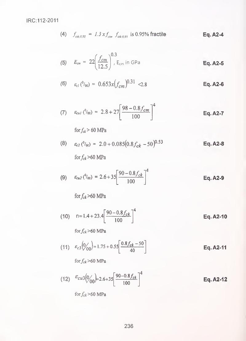
IRC:112-2011
W /c«.« = i-^^l,. is0.95%fractileam J clk:0.9SEq.A2-4
(5) = 22Jem
Vl2,S;, Ecm in GPa Eq.A2-5
Eq.A2-6
(7) ('/oo) = 2.8 + 2798-0.8/,
i4cm
100
for/cifc>60MPa
(8) f/oo) = 2,0 + 0.085(0.8f^k - 50f^^
for/d>60MPa
(9) ecu2{X) + 3590-0.8/̂ ^
100
i4
for/ei>60MPa
90-0.8/,^
too(10) n=L4 + 23.4
forfck>60 MPa
(11) .c3(%o)=1.75.0.55[M^-
for^*>60MPa
(12) ^^«3(%q)=2.6-h35
for/cfe>60 MPa
90-0.8/,^
100
i4
Eq.A2-7
Eq.A2-8
Eq.A2-10
Eq.A2-11
Eq.A2-12
236
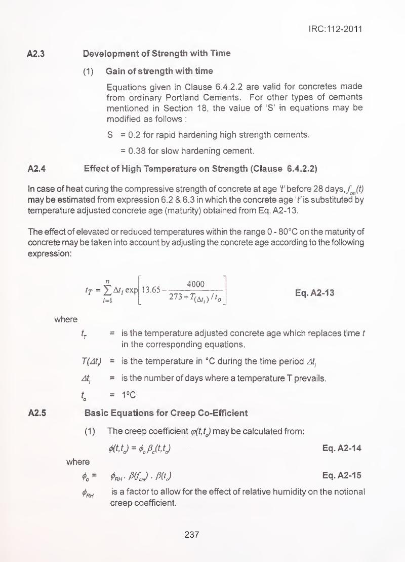
IRC: 11 2-2011
A2.3 Development of Strength with Time
(1) Gain of strength with time
Equations given in Clause 6.4.2.2 are valid for concretes madefrom ordinary Portland Cements. For other types of cements
mentioned in Section 18, the value of 'S' in equations may be
modified as follows
:
S = 0.2 for rapid hardening high strength cements.
= 0.38 for slow hardening cement.
A2.4 Effect of High Temperature on Strength (Clause 6.4.2.2)
In case of heat curing the compressive strength of concrete at age f before 28 days,f^Jt)
may be estimated from expression 6.2 & 6.3 in which the concrete age 'f'is substituted by
temperature adjusted concrete age (maturity) obtained from Eq. A2-1 3.
The effect of elevated or reduced temperatures within the range 0 - 80°C on the maturity of
concrete may be taken into account by adjusting the concrete age according to the following
expression:
/=i
where
A .-^r. 4000if = 2^A//exp 13.65-
273 + 7(^j//^Eq.A2»13
tj = is the temperature adjusted concrete age which replaces time t
in the corresponding equations.
T(At) = is the temperature in X during the time period At.
At. = is the number of days where a temperature T prevails.
f = 1°C0
A2.5 Basic Equations for Creep Co-Efficient'
(1) The creep coefficient <p(t, ij may be calculated from:
mtj^tm Eq.A2..14
where
t= *^-WJ-m Eq.A2-15
<l>f^is a factor to allow for the effect of relative humidity on the notional
creep coefficient.
237
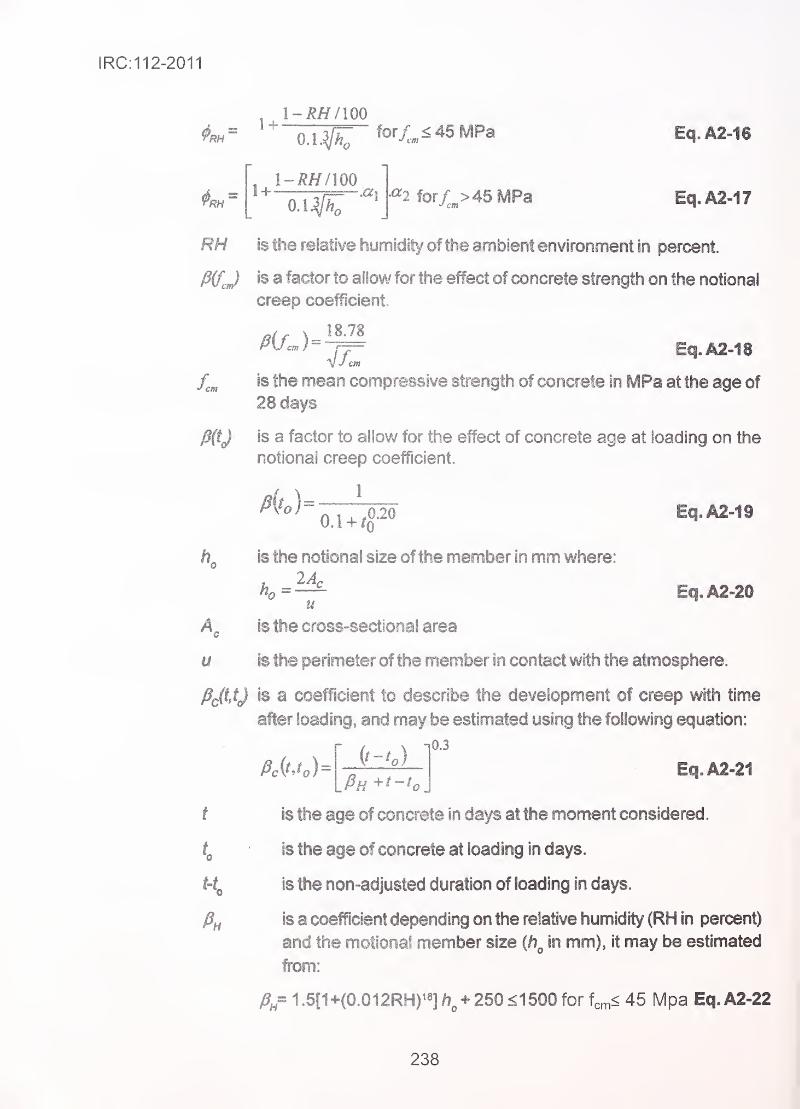
IRC:112-2011
1~RH/100 -
'
, i-RH/mOA^ -^2 for,/;^>45MPa Eq.A2-17
RH is the relative humidity of the ambient environment iri percent.
J3(f^j is a factor to allow for the effect of concrete strength on the notional
creep coefficient.
TF" Eq.A2-18
is the mean compressive strength of concrete in MPa at the age of
28 days
fi(tj is a factor to allow for the effect of concrete age at loading on the
notional creep coefficient.
is the notional size of the member in mm where:
ho=— Eq.A2-20u
is the cross-sectional area
u is the perimeter of the member in contact with the atmosphere.
PJitJ is a coefficient to describe the development of creep with time
after loading, and may be estimated using the following equation:
0.3
Eq.A2.21
t ' is the age of concrete in days at the moment considered
.
• is the age of concrete at loading in days.
is the non-adjusted duration of loading in days.
fi„ is a coefficient depending on the relative humidity (RH in percent)
and the motional member size {h^ in mm), it may be estimated
from:
1 .5[1+(0.012RH)^«] + 250 <1500 for fcm< 45 Mpa Eq.A2-22
238
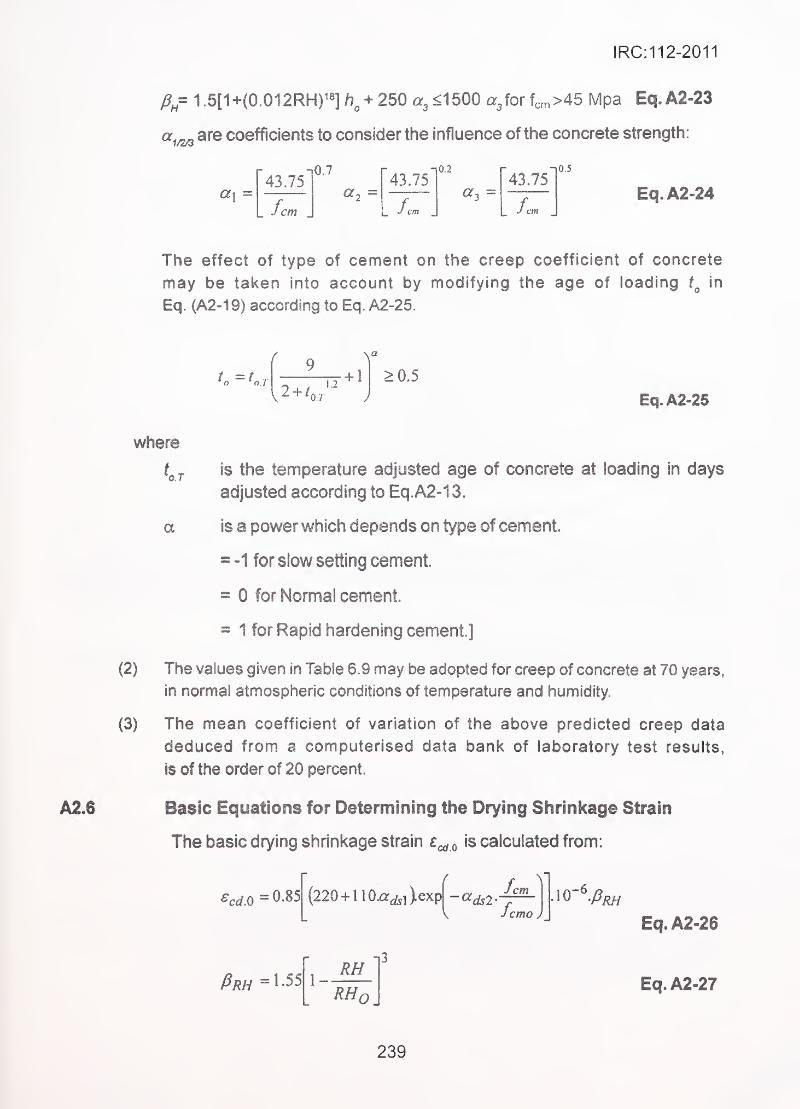
IRC:112-2011
fi= 1.5[1+(0.012RH)^s] /?^ + 250 a^<^bQO ajor U>45 Mpa Eq.A2-23
are coefficients to consider the influence of the concrete strength:
"43.75"0.7 "43.75'
0.2"43.75"
a, = «3 =
_ fern
0.5
Eq.A2=24
The effect of type of cement on the creep coefficient of concrete
may be taken into account by modifying the age of loading in
Eq. (A2-1 9) according to Eq. A2-25.
A2.6
L - L r
2 + 11.2
+ 1
0 /
>0.5
Eq.A2-25
where
is the temperature adjusted age of concrete at loading in days
adjusted according to Eq.A2-13.
a is a power which depends on type of cement.
= -1 for slow setting cement.
'
: = 0 for Normal cement. ..
= 1 for Rapid hardening cement.]
(2) The values given in Table 6.9 may be adopted for creep of concrete at 70 years,
in normal atmospheric conditions of temperature and humidity
(3) The mean coefficient of variation of the above predicted creep data
deduced from a computerised data bank of laboratory test results,
Is of the order of 20 percent.
Basic Equations for Determining the Drying Shrinkage Strain
The basic drying shrinkage strain e^ ^ is calculated from:
^cd.O = 0.85
/^/?//=l-55
(220 + 1 10xr^,>exp -a^2 cm
fccmo J
1-RH
-i3
RHO.
Eq.A2-26
Eq.A2-27
239
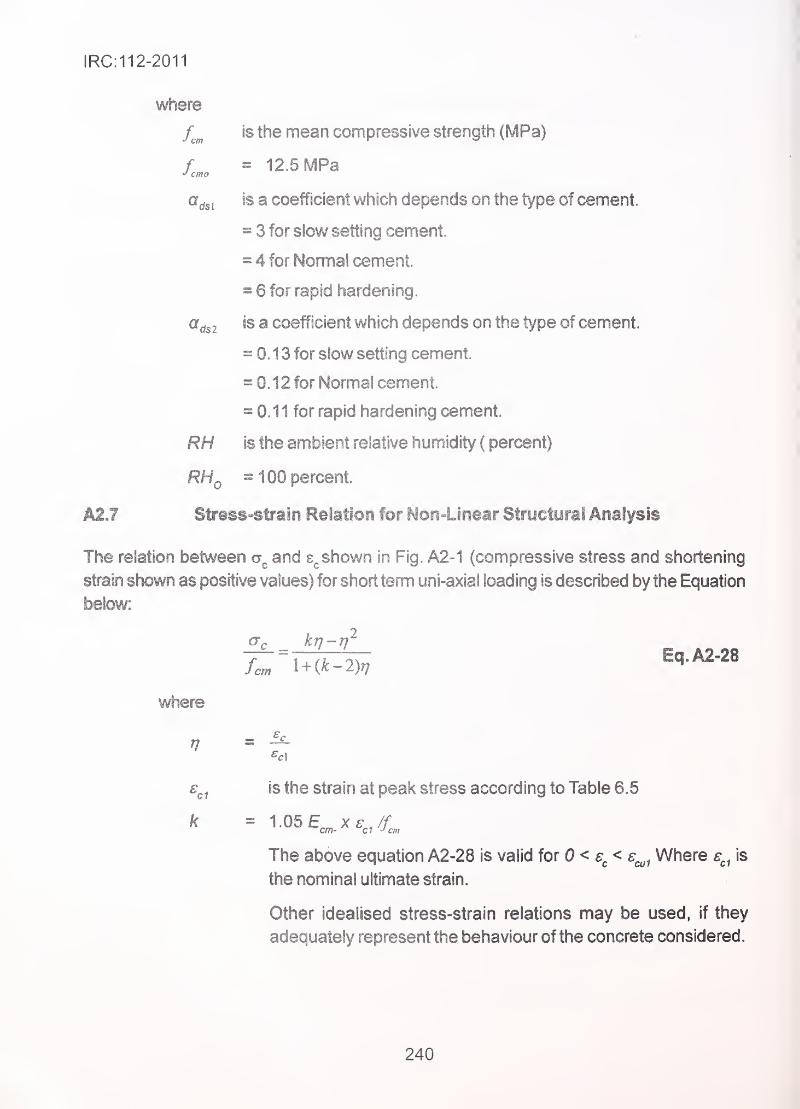
IRC:112-2011
where
J cmo
aas I
'ds2
RH
is the mean compressive strength (MPa)
= 12.5 MPa
is a coefficient which depends on the type of cement.
= 3 for slow setting cement.
= 4 for Nomna! cement.
= 6 for rapid hardening
.
is a coefficient which depends on the type of cement.
= 0.13 for slow setting cement.
= 0.12 for Norma! cement.
= 0.11 for rapid hardening cement.
is the ambient relative humidity ( percent)
= 100 percent.
A2J Stress-strain Relation for Non-Linear Structural Analysis
The relation between and shown in Fig. A2-1 (compressive stress and shortening
strain shown as positive values) for short term uni-axial loading is described by the Equation
below:
Eq.A2-28
where
'C1is the strain at peak stress according to Table 6.5
1.05 E.„ X€^,/f-™ C? cmcm-
The above equation A2-28 is valid for 0< s^< s^^ Where e^^ is
the nominal ultimate strain.
Other idealised stress-strain relations may be used, if they
adequately represent the behaviour of the concrete considered.
240
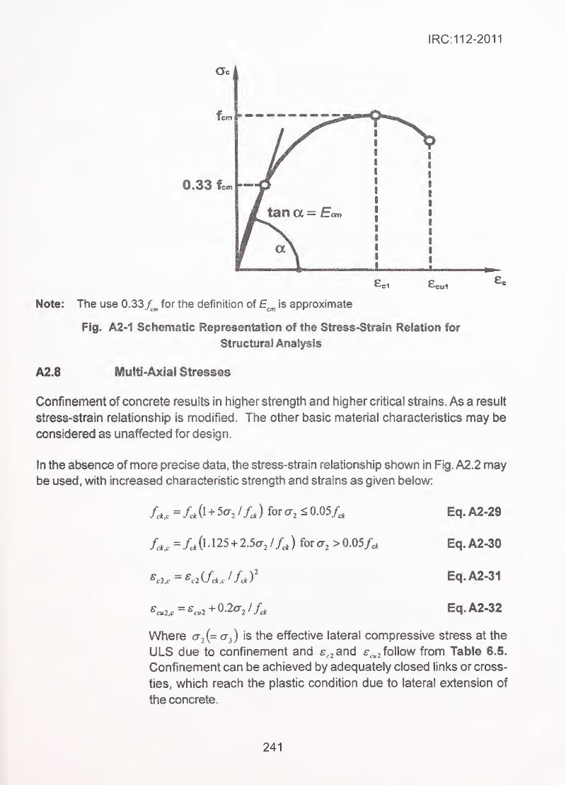
IRC:112-2011
Note: The use 0.33 /^^ for the definition of E^^ is approximate
Fig. A2>1 Schematic Representation of the Stress-Strain Relation for
Structural Analysis
A2.8 lyiyltl-Axlal Stresses
Confinement of concrete results in higher strength and higher critical strains. As a result
stress-strain relationship is modified. The other basic material characteristics may be
considered as unaffected for design.
In the absence of more precise data, the stress-strain relationship shown in Fig. A2.2 maybe used, with increased characteristic strength and strains as given below:
s
'
/c*.c= Lk 0 + 3^72 / ) for < 0.05/^
.Eq. A2-29
/c*.c =/c*0 l25 + 2.5a-2/Xj forcr^ >0.05/^ - Eq,A2-30
^a,-^c2iUJfJ Eq.A2-31
^c»2.c=^c.2+0-2o-2//., Eq.A2-32
Where a^{^ is the effective lateral compressive stress at the
ULS due to confinement and s,^ and e^^^ follow from Table 6.5.
Confinement can be achieved by adequately closed links or cross-
ties, which reach the plastic condition due to lateral extension of
the concrete.
241
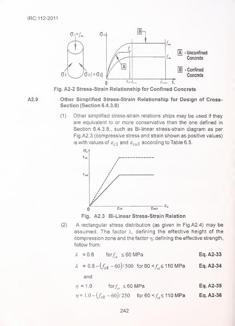
IRC:112-2011
A2J
[a] - Unconfined
Concrete
[U -Confined
ConciBte
0 ^™ £c;,c £™.'.c £5
Fig. A2-2 Stress-Strain Relationship for Confined Concrete
Other Simplified Stress-Strain Relationship for Design of Cross-
Section (Section 6.4.3.8)
(1)
(2)
Other simplified stress-strain relations ships may be used if they
are equivalent to or more conservative than the one defined in
Section 6.4.3.8., such as Bi-linear stress-strain diagram as per
Fig.A2.3 (compressive stress and strain shown as positive values)
is with values of ^^.3 and s^^^^ according to Table 6.5.
EcS Ecus ^
Fig. A2.3 Bi-Linear Stress-Strain Relation
A rectangular stress distnbution (as given in Fig.A2.4) may be
assumed. The factor X, defining the effective height of the
compression zone and the factor r\, defining the effective strength,
follow from:
A =0.8 for4 < 60 MPa Eq.A2-33
A = 0.8- (/^^ -60)/ 500 for60<y;,<110MPa Eq.A2-34
and
77 =1.0 for/, < 60 MPa Eq. A2-35
Tj= 1.0-(/c^ -60)/250 for60<X,^110MPa Eq.A2-36
242
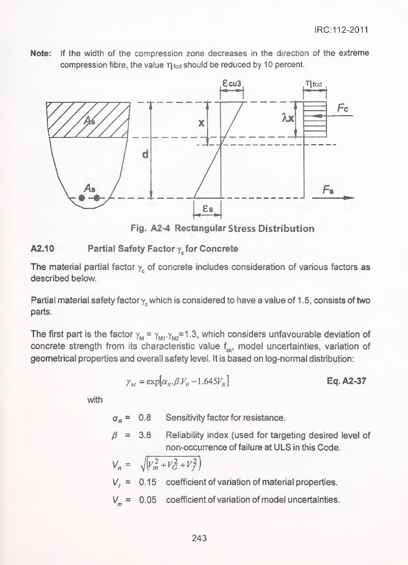
IRC:112-2011
Note.' If the width of the compression zone decreases in the direction of the extreme
compression fibre, the value r|fcd should be reduced by 10 percent.
£ai3 Tjfcd
A2.10
Fig. A2-4 Rectangular Stress Distribution
Partial Safety Factor for Concrete
The material partial factor of concrete includes consideration of various factors as
described below.
Partial material safety factor y^. which is considered to have a value of 1.5, consists oftwo
parts.
The first part is the factor y„ = yy2"1.3, which considers unfavourable deviation of
concrete strength from its characteristic value f^^, model uncertainties, variation of
geometrical properties and overall safety level. It is based on log-normal distribution:
r^=exph./?.F,-1.645J^J Eq.A2-37
with
0.8 Sensitivity factor for resistance.
3.8 Reliability index (used for targeting desired level of
non-occurrence of failure at ULS in this Code.
Vf = 0.15 coefficient of variation of material properties.
VL = 0.05 coefficient of variation of model uncertainties.
243
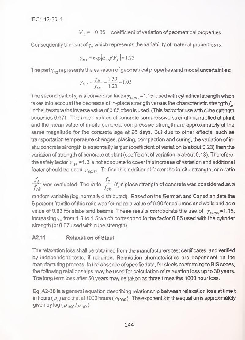
IRC:112-2011
Vq = 0.05 coefficient of variation of geometricai properties.
Consequently the part of which represents the variability of material properties is:
The part represents the variation of geometrical properties and model uncertainties:
r.n 1.23
The second part of is a conversion factor/^^„y=1 . 1 5, used with cylindrical strength which
takes into account the decrease of in-place strength versus the characteristic strength^^.
In the literature the inverse value of 0.85 often is used. (This factor for use with cube strength
becomes 0.67). The mean values of concrete compressive strength controlled at plant
and the mean value of in-situ concrete compressive strength are approximately of the
same magnitude for the concrete age at 28 days. But due to other effects, such as
transportation temperature changes, placing, compaction and curing, the variation of in-
situ concrete strength is essentially larger (coefficient of variation is about 0.23) than the
variation of strength of concrete at plant (coefficient of variation is about 0.13). Therefore,
the safety factor y^ =1.3 is not adequate to cover this increase of variation and additional
factor should be used fcom To find this additional factor the in-situ strength, or a ratio
fs fs~f~ was evaluated. The ratio in place strength of concrete was considered as aJck Jck
'
random variable (log-normally distributed). Based on the German and Canadian data the
5 percent fractile of this ratio was found as a value of 0.90 for columns and walls and as a
value of 0.83 for slabs and beams. These results corroborate the use of /^o„v=1.15,
increasing from 1.3 to 1 .5 which correspond to the factor 0.85 used with the cylinder
strength (or 0.67 used with cube strength).
A2.11 Relaxation of Steel
The relaxation loss shall be obtained from the manufacturers test certificates, and verified
by independent tests, if required. Relaxation characteristics are dependent on the
manufacturing process. In the absence of specific data, for steels conforming to BIS codes,
the following relationships may be used for calculation of relaxation loss up to 30 years.
The long term loss after 50 years may be taken as three times the 1 000 hour loss.
Eq. A2-38 is a general equation describing relationship between relaxation loss at time t
in hours ( p, ) and that at 1000 hours ( pi qqq ). The exponent k in the equation is approximately
given by log (p,ooo/Pioo)-
244
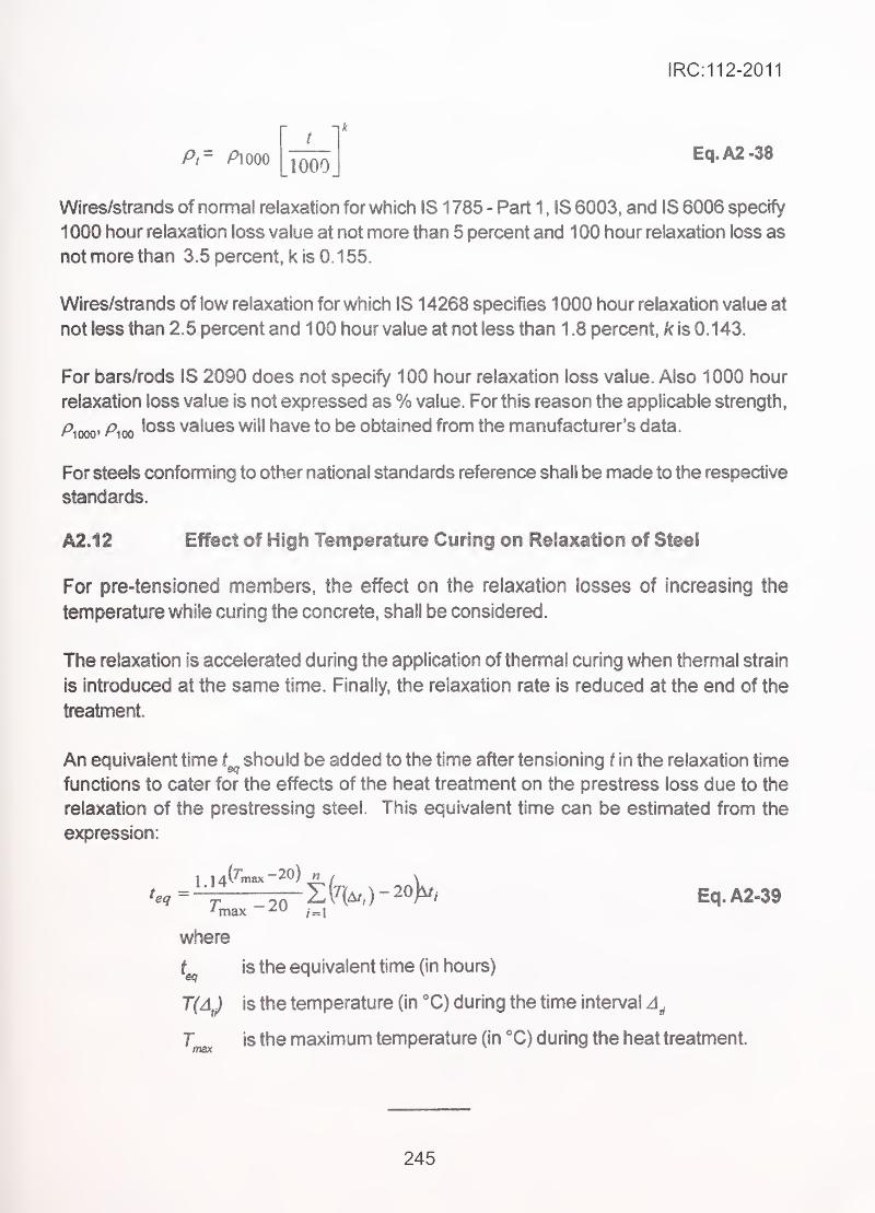
IRC:112-2011
A" A 000 1000Eq.A2-38
Wires/strands of normal relaxation for which IS 1785 - Part 1 , IS 6003, and IS 6006 specify
1 000 hour relaxation loss value at not more than 5 percent and 1 00 hour relaxation loss as
not more than 3.5 percent, k is 0.1 55.
Wires/strands of low relaxation for which IS 14268 specifies 1000 hour relaxation value at
not less than 2.5 percent and 1 00 hour value at not less than 1 .8 percent, k is 0.143.
For bars/rods IS 2090 does not specify 100 hour relaxation loss value. Also 1000 hour
relaxation loss value is not expressed as % value. For this reason the applicable strength,
Aooo' Pirn 'OSS values will have to be obtained from the manufacturer's data.
For steels conforming to other national standards reference shall be made to the respective
standards.
A2.12 Effect of High Temperature Curing on Relaxation of Steel
For pre-tensloned members, the effect on the relaxation losses of increasing the
temperature while curing the concrete, shall be considered
.
The relaxation is accelerated during the application ofthemnal curing when thermal strain
is introduced at the same time. Finally, the relaxation rate is reduced at the end of the
treatment.
An equivalent time should be added to the time after tensioning t in the relaxation time
functions to cater for the effects of the heat treatment on the prestress loss due to the
relaxation of the prestressing steel. This equivalent time can be estimated from the
expression:
Eq.A2.39
where
t is the equivalent time (in hours)
T(AJ is the temperature (in "C) during the time interval
T is the maximum temperature (in X) during the heat treatment.
245
IRC:112-2011
ANNEXURE A-3
LIST OF STANDARDS AND OTHER NORMATIVE REFERENCES
(1) List of Bureau of Indian Standards Codes
Sr. Standard
Ho. Ho Title
(1) 18 269:1989 Specification for 33 grade ordinary portland cement(Fourth Revision)
(2) 18 383:1970 Speciftcation for coarse and fine aggregates from
natural sources for concrete (Second Revision)
(3) IS 432: Parti : 1982 Specification for mild steel and medium tensile steel
bars and hard-drawn steel wire for concrete reinforcement:
Part 1 mild steel and medium tensile steel bars
(Third Revision)
(4) 18432 Part 2: 1982 Specification for mild steel and medium tensile steel
bars and hard-drawn steel wire for concrete reinforcement:
Part-2 hard-drawn steel wire (Third Revision)
(5) 18 455:1989 Specification for Portland slag cement (Fourth
Revision)
(6) IS 456 : 2000 ' Code of practice for plain and reinforced concrete
(7) IS 516 : 1 959 Method of test for strength of concrete
(8) IS 822 : 1 970 Code of procedure for inspection of welds
(9) IS 1199 : 1 959 Methods of sampling and analysis of concrete
(10) IS 1343 : 2010 Code of practice for prestressed concrete
(11) IS 1489 :Part 1 : 1991 Specification for portland pozzolana cement Part-1
FlyAsh based (Third Revision)
(12) IS 1608 : 1995 Mechanical testing of metals - Tensile Testing (Third
Revision)
(13) IS 1641 : 1988 Code of practice for fire safety of building (General :
General principles of fire grading and classification)
(14) IS 1642 : 1989 Fire safety of building (general : details of construction -
. code of practice)
(1 5) IS 1765 : 1 980 Direct current potentiometers (Second Revision)
246
IRC:112-2011
(16) 181785: Parti : 1983 Specification for Plain Hard-drawn Steel Wire for
Prestressed Concrete - Part 1 : Cold Drawn Stress-relieved
Wire (Second Revision)
(17) 18 1786 : 2008 Specification for high strength deformed steel bars and
wires for concrete reinforcement (Third Revision)
(1 8) IS 2090 : 1 983 Specification for high tensile steel bars used in prestressed
concrete (First Revision)
(19) 18 2386 : Part 1 : 1963 Methods of test for Aggregates for Concrete - Part 1 :
Particle Size and Shape
(20) 18 2386 : Part 2: 1963 Methods of test for Aggregates for Concrete - Part 2 :
Estimation of deleterious materials and organic impurities
(21) 18 2386 : Part 3: 1963 Methods of test for Aggregates for Concrete - Part 3 :
Specific gravity, density, voids, absorption and bulking
(22) IS 2386 : Part 4 : 1963 Methods of test for Aggregates for Concrete - Part 4 :
Mechanical properties
(23) 18 2386: Part 5: 1963 Methods of test for Aggregates for Concrete - Part 5
:Soundness
(24) 182386 : Part 6: 1963 Methods of test for Aggregates for Concrete - Part 6 :
* Measuring mortar making properties of fine aggregates
(25) IS 2386 : Part 7 : 1 963 Methods of test forAggregates for Concrete - Part 7 : Alkali
Aggregate Reactivity
(26) IS 2386 : Part 8 : 1963 Methods of test for Aggregates for Concrete - Part 8 :
Petrographic Examination
(27) 18 2751 : 1979 Code of practice for Welding of Mild Steel Plain and
Defonned Bars For Reinforced Concrete Construction (First
Revision)
(28) 18 3025 : Part 17:1984 Methods of sampling and test (Physical and chemical) for
water and wastewater : Part 17 : Non-filterable residue
(Total suspended solids) (First Revision)
(29) IS 3025 : Part 18:1984 Methods of sampling and test (Physical and Chemical) for
water and wastewater : Part 18 : Volatile and fixed residue
(Total filterable and non-filterable) (First Revision)
(30) IS 3025 : Part 22:1986 Methods of sampling and test (Physical and Chemical) for
water and wastewater : Part 22 : Acidity (First Revision)
247
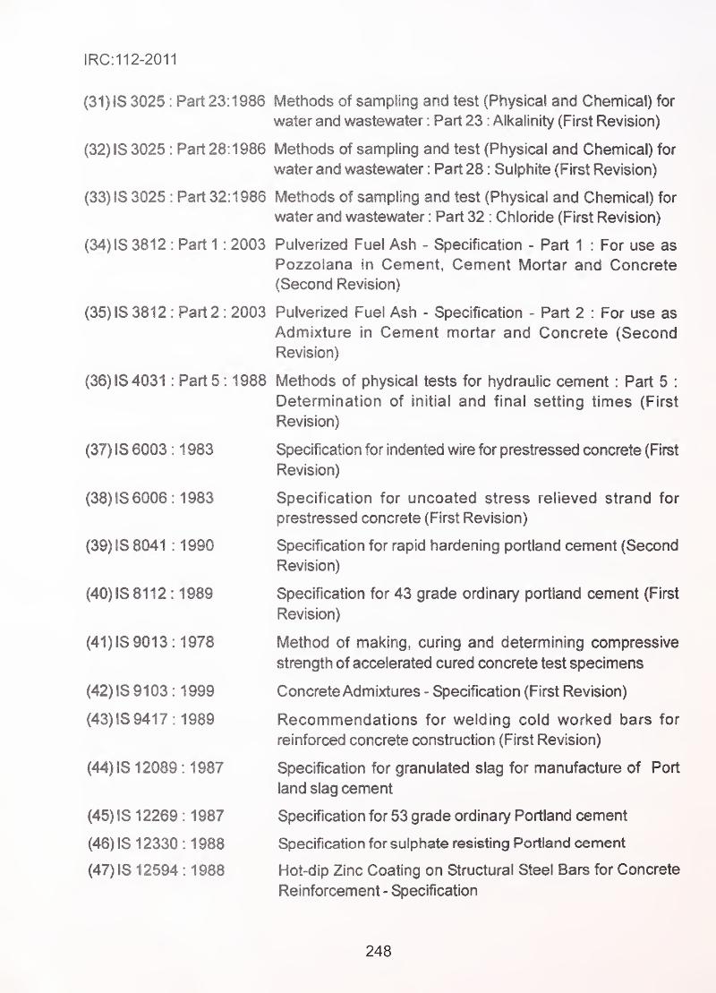
IRC:112-2011
(31) IS 3025 : Part 23: 1986 Methods of sampling and test (Physical and Chemical) for
water and wastewater : Part 23 : Alkalinity (First Revision)
(32) IS 3025 : Part 28:1986 Methods of sampling and test (Physical and Chemical) for
water and wastewater : Part 28 : Sulphite (First Revision)
(33) IS 3025 : Part 32:1986 Methods of sampling and test (Physical and Chemical) for
water and wastewater : Part 32 : Chloride (First Revision)
(34) IS 3812 : Part 1 : 2003 Pulverized Fuel Ash - Specification - Part 1 : For use as
Pozzolana in Cement, Cement Mortar and Concrete
(Second Revision)
(35) IS 3812 : Part 2: 2003 Pulverized Fuel Ash - Specification - Part 2 : For use as
Admixture in Cement mortar and Concrete (Second
Revision)
(36) IS 4031 : Part 5: 1988 Methods of physical tests for hydraulic cement : Part 5 :
Determination of initial and final setting times (First
Revision)
(37) IS 6003 : 1 983 Specification for indented wire for prestressed concrete (First
Revision)
(38) IS 6006 : 1983 Specification for uncoated stress relieved strand for
prestressed concrete (First Revision)
(39) IS 8041 : 1 990 Specification for rapid hardening portland cement (Second
Revision)
(40) IS8112 : 1989 Specification for 43 grade ordinary portland cement (First
Revision)
(41) IS 9013 : 1978 Method of making, curing and determining compressive
strength of accelerated cured concrete test specimens
(42) IS 91 03 : 1999 Concrete Admixtures - Specification (First Revision)
(43) IS 941 7 : 1989 Recommendations for welding cold worked bars for
reinforced concrete construction (First Revision)
(44) IS 12089 : 1987 Specification for granulated slag for manufacture of Port
land slag cement
(45) IS 1 2269 : 1 987 Specification for 53 grade ordinary Portland cement
(46) IS 1 2330 : 1 988 Specification for sulphate resisting Portland cement
(47) IS 12594 : 1988 Hot-dip Zinc Coating on Structural Steel Bars for Concrete
Reinforcement - Specification
248
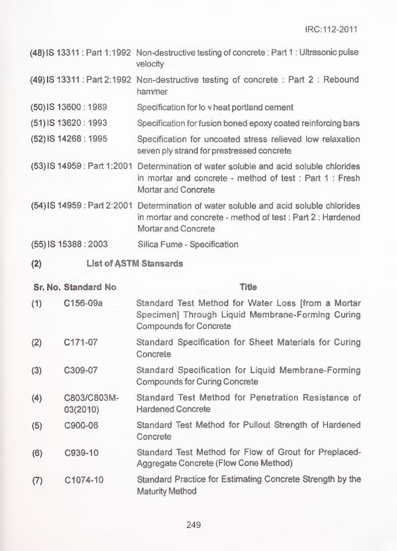
IRC:112-2011
(48) 18 13311
(49) 1813311
Part 1 : 1 992 Non-destructive testing of concrete : Part 1 : Ultrasonic pulse
velocity
Part 2: 1992 Non-destructive testing of concrete : Part 2 : Rebound
hammer
(50) 1813600
(51) 1813620
(52) 18 14268
: 1 989 Specification for lo v heat portland cement
: 1 993 Specification for fusion boned epoxy coated reinforcing bars
: 1995 Specification for uncoated stress relieved low relaxation
seven ply strand for prestressed concrete
(53) IS 14959 : Part 1 :2001 Determination of water soluble and acid soluble chlorides
in mortar and concrete - method of test : Part 1 : Fresh
Mortar and Concrete
(54) IS 14959 : Part 2:2001 Determination of water soluble and acid soluble chlorides
in mortar and concrete - method of test : Part 2 : Hardened
Mortar and Concrete
(55)1816388
(2)
: 2003 Silica Fume - Specification
List ofASTM Stonsards
Sr. No. Standard No
(1) C156-09a
(2)
(3)
(4)
C171-07
C309-07
C803/C803M-
03(2010)
(5) C900-06
(6) C939-10 •
(7) CI 074-10
Title
Standard Test Method for Water Loss [from a Mortar
Specimen] Through Liquid Membrane-Forming Curing
Compounds for Concrete
Standard Specification for Sheet Materials for Curing
Concrete
Standard Specification for Liquid Membrsne-Forming
Compounds for Curing Concrete
Standard Test Method for Penetration Resistance of
Hardened Concrete
Standard Test Method for Pullout Strength of Hardened
Concrete
Standard Test Method for Flow of Grout for Preplaced-
Aggregate Concrete (Flow Cone Method)
Standard Practice for Estimating Concrete Strength by the
Maturity Method
249
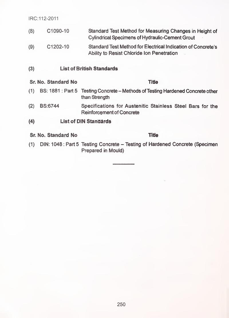
IRC: 11 2-2011
(8) CI 090-1 0 Standard Test Method for Measuring Changes in Height of
Cylindrical Specimens of Hydraulic-Cement Grout
(9) CI 202-1 0 Standard Test Method for Electrical Indication of Concrete's
Ability to Resist Chloride Ion Penetration
(3) List of British Standards
Sr. No. Standard No Title
(1 ) BS: 1 881 : Part 5 Testing Concrete- Methods ofTesting Hardened Concrete other
than Strength
(2) BS:6744 Specifications for Austenitic Stainless Steel Bars for the
Reinforcement of Concrete
(4) List of DIN Standards
Sr. No. Standard No Title
(1) DIN: 1048 : Part 5 Testing Concrete - Testing of Hardened Concrete (Specimen
Prepared in Mould)
250
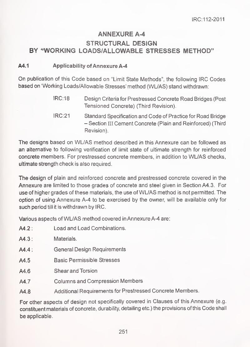
IRC:112-2011
ANNEXUREA^STRUCTURAL DESIGN
BY ^WORKING LOADS/ALLOWABLE STRESSES METHOD"
A4.1 Applicability ofAnnexureA-4
On publication of this Code based on "Limit State Methods", the following IRC Codesbased on 'Working Loads/Allowable Stresses' method (WL/AS) stand withdrawn:
1RC:1 8 Design Criteria for Prestressed Concrete Road Bridges (Post
Tensioned Concrete) (Third Revision).
IRC:21 Standard Specification and Code of Practice for Road Bridge
- Section m Cement Concrete (Plain and Reinforced) (Third
Revision).
The designs based on WL/AS method described in this Annexure can be followed as
an alternative to following verification of limit state of ultimate strength for reinforced
concrete members. For prestressed concrete members, in addition to WL/AS checks,
ultimate strength check is also required.
The design of plain and reinforced concrete and prestressed concrete covered in the
Annexure are limited to those grades of concrete and steel given in Section A4.3. For
use of higher grades of these materials, the use of WL/AS method is not permitted. The
option of using Annexure A-4 to be exercised by the owner, will be available only for
such period till it is withdrawn by IRC.
Various aspects of WL/AS method covered in Annexure A-4 are:
A4.2: Load and Load Combinations.
A4.3: Materials.
A4.4: General Design Requirements
A4.5 Basic Permissible Stresses
A4.6 Shear and Torsion
A4.7 Columns and Compression Members
A4.8 Additional Requirements for Prestressed Concrete Members
For other aspects of design not specifically covered in Clauses of this Annexure (e.g.
constituent materials of concrete, durability, detailing etc.) the provisions of this Code shall
be applicable.
251
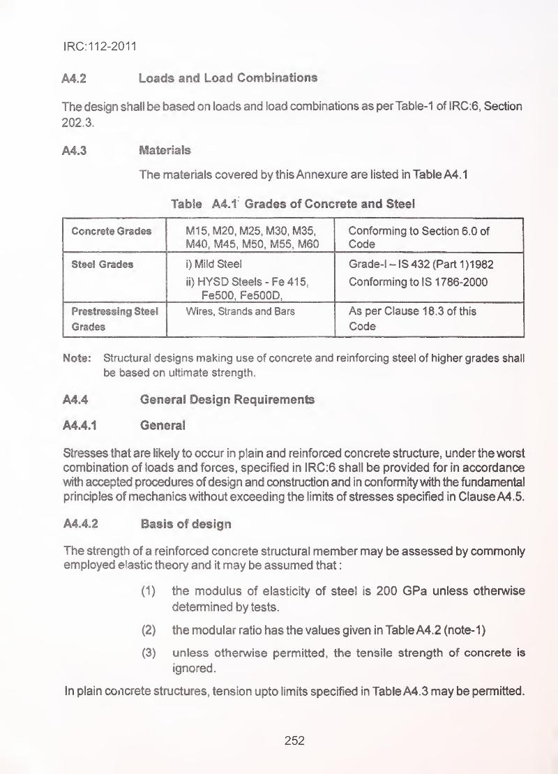
IRC:112-2011
A4.2 Loads and Load Combinations
The design shall be based on loads and load combinations as perTable-1 of IRC:6, Section
202.3.
A4.3 Materials
The materials covered by thisAnnexure are listed in Table A4.1
Table A4.1 Grades of Concrete and Steel
Concrete Grades M15, M20, M25, M30. M35,
M40, M45, M60, M55, M60Conforming to Section 6.0 of
Code
Steel Grades i) Mild Steel
ii) HYSD Steels -Fe 415,
FeSOO. FeSOOD.
Grade-I - IS 432 (Part 1)1982
Conforming to IS 1786-2000
Prestressing Steel
Grades
Wires, Strands and Bars As per Clause 18.3 of this
Code
Note: Structural designs making use of concrete and reinforcing steel of higher grades shall
be based on ultimate strength.
A4.4 General Design Requirements
A4.4.1 General
Stresses that are likely to occur in plain and reinforced concrete structure, under the worst
combination of loads and forces, specified in IRC:6 shall be provided for in accordance
with accepted procedures of design and construction and in conformity with the fundamental
principles of mechanics without exceeding the limits of stresses specified in ClauseA4.5.
A4.4.2 Basis of design
The strength of a reinforced concrete structural member may be assessed by commonlyemployed elastic theory and it may be assumed that
:
(1) the modulus of elasticity of steel is 200 GPa unless othenwise
determined by tests.
(2) the modular ratio has the values given in Table A4.2 (note-1)
(3) unless otherwise permitted, the tensile strength of concrete is
Ignored.
In plain concrete staictures, tension upto limits specified in TableA4.3 may be pennitted.
252
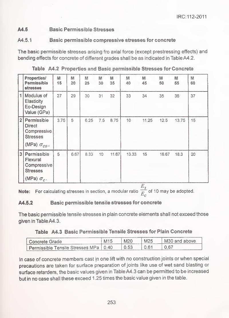
IRC:112-2011
A4.5 Basic Permissibie Stresses
A4.5.1 Basic permissible compressive stresses for concrete
The basic permissible stresses arising fro axial force (except prestressing effects) and
bending effects for concrete of different grades shall be as indicated in Table A4.2.
Table A4.2 Properties and Basic permissible Stresses for Concrete
Properties/
Permissible
m15
M20 25 30 35 40 45 50 55
M60
1 Modulus of
Elasticity
Ec-Design
Value (GPa)
27 29 30 31 32 33 34 35 36 37
2 Permissible
Direct
Compressive
Stresses
{MPa) aco,
3.75 5 625 7.5 8.75 10 11.25 12.5 13.75 15
3 Permissible
Flexural
Compressive
Stresses
(MPa) a,
.
5 6.67 J3 10 11.67 13.33 15 16.67 18.3 20
Note: For calculating stresses in section, a modular ratio ^ of 10 may be adopted.
A4.5.2 Basic permissible tensile stresses for concrete
The basic permissibie tensile stresses in plain concrete elements shall not exceed those
given in Table A4. 3..
Table A4.3 Basic Permissibie Tensile Stresses for Plain Concrete
Concrete Grade M15 M20 M25 M30 and above
Permissible Tensile Stresses MPa 0.40 0.53 0.61 0.67
In case of concrete members cast in one lift with no construction joints or when special
precautions are taken for surface preparation of joints like use of wet sand blasting or
surface retarders, the basic values given in Table A4. 3 can be permitted to be increased
but in no case shall these exceed 1 .25 times the basic value given in the table.
253
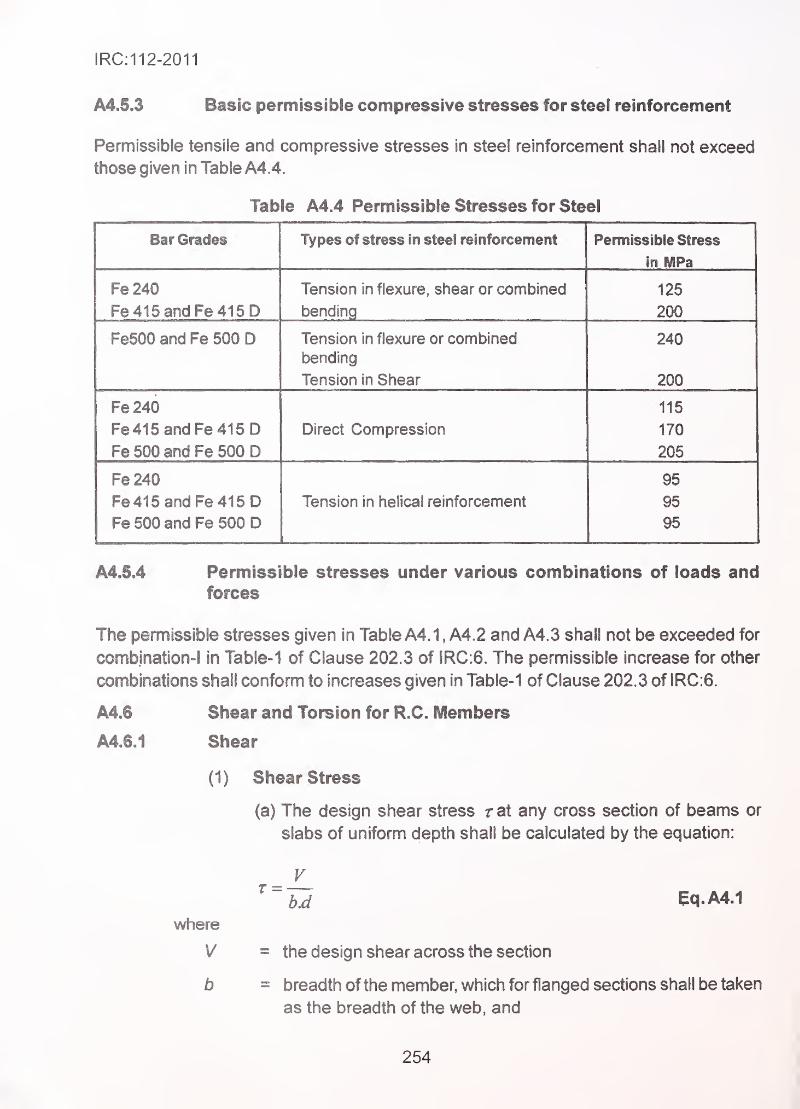
IRC:112-2011
A4.5.3 Basic permissible compressive stresses for steel reinforcement
Permissible tensile and compressive stresses in steel reinforcement shall not exceed
those given in Table A4.4.
Table A4.4 Permissible Stresses for Steel
1 y pt79 w oiivso in sicd i6inioivernsni rcillllSSiDie oliVSS
In MPa
Fe 240 Tpn^inn in fIpyi irp chpsr or rnmhinpH IOC
Fe 415 and Fe415D bending 200
FeSOO and Fe 500 D Tension in flexure or combined 240
bending
Tension in Shear 200
Fe240 115
Fe415and Fe415D Direct Compression 170
Fe 500 and Fe 500 D 205
Fe240 95
Fe 41 6 and Fe415D Tension in helical reinforcement 95
Fe 500 and Fe 500 D 95
A4.5.4 Permissible stresses under various combinations of loads andforces
The pennissibie stresses given in Table A4.1, A4.2 and A4.3 shall not be exceeded for
combjnation-1 in Table-1 of Clause 202.3 of IRC:6. The permissible increase for other
combinations shall conform to increases given in Table- 1 of Clause 202.3 of IRC:6.
A4.6 Shear and Torsion for R.C. Members
A4.6.1 Shear
(1) Shear Stress
(a) The design shear stress r at any cross section of beams or
slabs of uniform depth shall be calculated by the equation:
^~b.d eqA4.i
where
V = the design shear across the section
b = breadth of the member, which for flanged sections shall be taken
as the breadth of the web, and
254
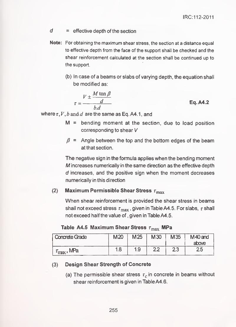
IRC:112-2011
= effective depth of the section
Note: For obtaining the maximum shear stress, the section at a distance equal
to effective depth from the face of the support shall be checked and the
shear reinforcement calculated at the section shall be continued up to
the support.
(b) In case of a beams or slabs of varying depth, the equation shall
be modified as:
V± A/ tan/?
r = Eq.A4.2
v\/here r, F, 5 and are the same as Eq. A4. 1 , and
M = bending moment at the section, due to load position
corresponding to shear V
P = Angle between the top and the bottom edges of the beam
at that section.
The negative sign in the fomnula applies when the bending moment
M increases numerically in the same direction as the effective depth
d increases, and the positive sign when the moment decreases
numerically in this direction
(2) Maximum Permissible Shear Stress rmax
When shear reinforcement is provided the shear stress in beams
shall not exceed stress r„,ax >Qiveri in Table A4.5. For slabs, r shall
not exceed half the value of,given in Table A4. 5.
Table A4.5 Maximum Shear Stress r^^^ MPa
Concrete Grade M20 M25 M30 M35 M40andabo^
1.8 1.9 22 23 25
(3) Design Shear Strength of Concrete
(a) The permissible shear stress in concrete in beams without
shear reinforcement is given in Table A4.6.
255
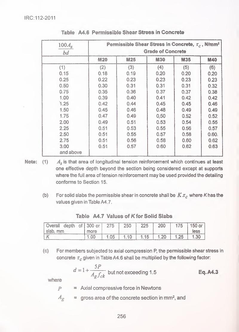
IRC:112-2011
Table A4.6 Permissible Shear Stress in Concrete
Permissible Shear Stress In Concrete, , N/rom^
bd Grade of Concrete
IM20 iyi25 M30 M35 M40
\V (2) (3) (4) (5) (6)
U.10 0.18 0.19 0.20 0.20 0.20
0.22 0.23 0.23 0.23 0.23
U.9U 0.30 0.31 0.31 0.31 0.32n 7*; 0.35 0.36 0.37 0.37 0.38
1 .yu 0.39 0.40 0.41 0.42 0.42
1 «zo 0.42 0.44 0.45 0.45 0.46
1 .ou 0.45 0.46 0.48 0.49 0.49
1.75 0.47 0.49 0,50 0.52 0.52
2.00 0.49 0.51 0.53 0.54 0.55
2.25 0.51 0.53 0.55 0.56 0.57
2.50 0.51 0.55 0.57 0.58 0.60.
2J5 0.51 0.56 0.58 0.60 0.62
3.00 0.51 0.57 0.60 0.62 0.63
and above
Note: (1) is that area of longitudinal tension reinforcement which continues at least
one effective depth beyond the section being considered except at supports
where the full area of tension reinforcement may be used provided the detailing
conforms to Section 15.
(b) For solid slabs the permissible shear in concrete shall be K.Tq where K has the
values given in Table A4.7.
Table A4.7 Values of K for Solid Slabs
Overall depth of
slab, mm300 or
more
275 250 225 200 175 150 or
less
K 1.00 1.05 1.10 1.15 1.20 1.25 1.30
(c) For members subjected to axial compression P, the permissible shear stress in
concrete given in Table A4.6 shall be multiplied by the following factor:
^ ^ 1 + t3ut not exceeding 1.5 Eq. A4.3^gJck
where
p = Axial compressive force in Newtons
Ag = gross area of the concrete section in mm^, and
256
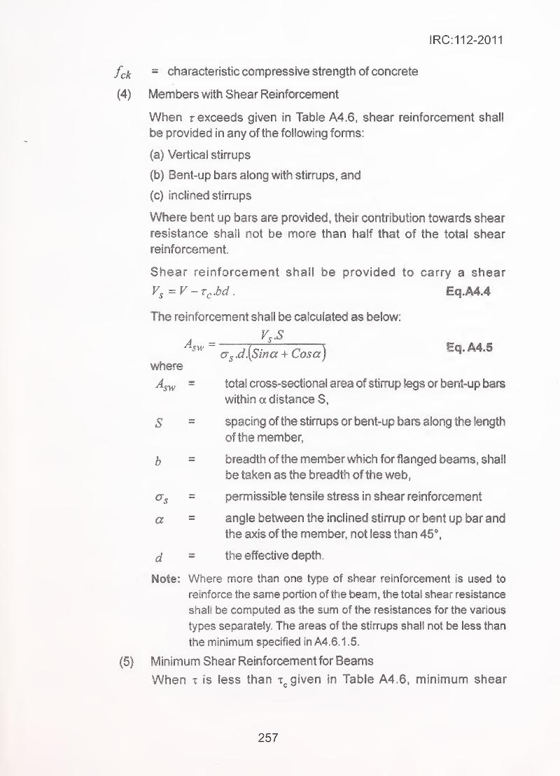
IRC:112-2011
= characteristic compressive strength of concrete
Members with Shear Reinforcement
When T exceeds given in Table A4.6, shear reinforcement shall
be provided in any of the following forms:
(a) Vertical stirrups
(b) Bent-up bars along with stirrups, and
(c) inclined stirrups
Where bent up bars are provided, their contribution towards shear
resistance shall not be more than half that of the total shear
reinforcement.
Shear reinforcement shall be provided to carry a shear
V, =V-r^.bd. Eq.A4.4
The reinforcement shall be calculated as below:
"a,.d{Sina + Cosa)
^^'^
where
^sw = total cross-sectional area of stirrup legs or bent-up bars
within a distance S,
S = spacing of the stirrups or bent-up bars along the length
of the member,
b = breadth of the member which for flanged beams, shall
- be taken as the breadth of the web
,
€Tg = permissible tensile stress in shear reinforcement
a = angle between the inclined stirrup or bent up bar and
the axis of the member, not less than 45*.
d - the effective depth.
Note: Where more than one type of shear reinforcement is used to
reinforce the same portion of the beam, the total shear resistance
shall be computed as the sum of the resistances for the various
types separately. The areas of the stirrups shall not be less than
the minimum specified in A4. 6. 1.5.
Minim.um Shear Reinforcement for Beams
When X is less than t given in Table A4.6, minimum shear
257
IRC:112-2011
reinforcement for beams shall be provided in accordance with the
following:
Pw.min. = -^=:Qg^y. ,/v<415MPa . / Eq,A4.6
(6) Maximum spacing of stirrups shall be limited to one-half times the
depth of the beam subject to a maximum of 300 mm. Stirrups shall
pass round, or othenvise be secured to be appropriate longitudinal
tensile reinforcement. The ends of stirrups shall be adequately
anchored in the compression zone. Where for practical purposes it is
found necessary to anchor the ends of the stimjps in the tensile zone,
full anchorage length shall be provided.
(7) Bent-up bars shall be carried through a depth at least equal to
the lever arm of the resisting moment and adequately anchored in
accordance with Section 6 and Clause 16.5. The spacing of the bent-
up bar measured at the level of neutral axis and in the direction of
longitudinal axis of the beam, shall not exceed three-quarter the
effective depth of the beam.
A4.6.2 Torsion
(1) General
in structures where torsion is required to maintain equilibrium,
members shall be designed for torsion. However, for such
indeterminate structures where torsion can be eliminated by
releasing redundant restraints, no specific design for torsion is
necessary provided torsional stiffness is neglected in the calculation
of internal forces. Adequate control of any torsional cracking is
provided by the shear reinforcement as per Clause A4.6.1.
Torsional reinforcement is not calculated separately for torsion
alone. Instead the total longitudinal reinforcement is determined
for a fictitious bending moment which is a function of actual bending
moment and torsion; similarly web reinforcement is determined for
a fictitious shear which is a function of actual shear and torsion.
. The design rules shall apply to beams of solid rectangular cross-
section. However, these clauses may also be applied to flanged
beams by substituting bw for b, in which case they are generally
conservative.
(2) Critical Section
Sections located less than a distance d. from the face of the support
may be designed for the same torsion as computed at a distance
d, where d is the effective depth.
258
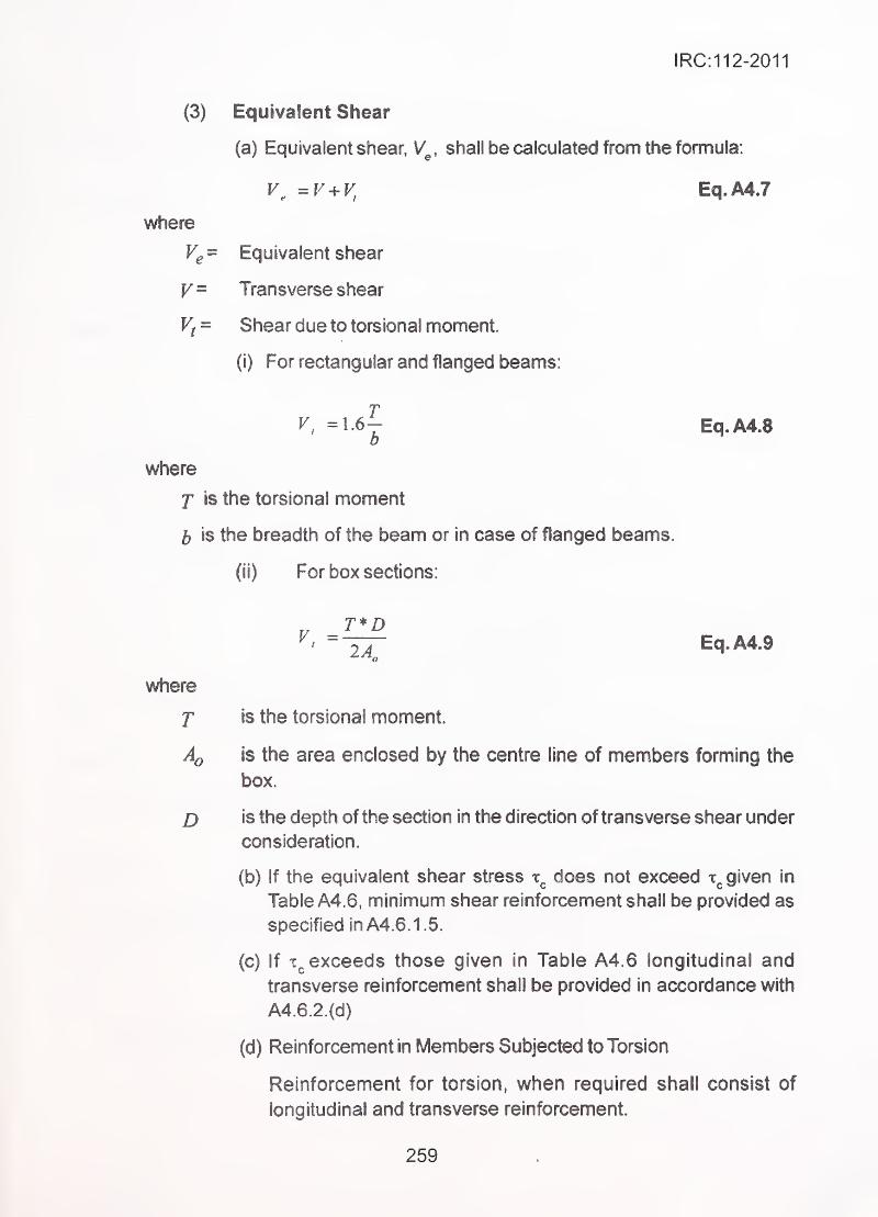
IRC:112-2011
(3) Equivalent Shear
(a) Equivalent shear, V^, shall be calculated from the fomnula:
=r'^ + F, Eq.A4.7
where
Vg= Equivalent shear
V= Transverse shear
Vf = Shear due to torsional moment.
(i) For rectangular and flanged beams:
V, =1^6^ Eq.A4.8
where
T is the torsional moment
5 is the breadth of the beam or in case of flanged beams.
(ii) For box sections:
- _T*D~~2A~ Eq.A4.9
where
f is the torsional moment. '
•
'.
Aq is the area enclosed by the centre line of members forming the
box.
D is the depth of the section in the direction of transverse shear under
consideration.
(b) If the equivalent shear stress does not exceed given in
Table A4.6, minimum shear reinforcement shall be provided as• specified in A4. 6. 1.5.
(c) If exceeds those given in Table A4.6 longitudinal and
transverse reinforcement shall be provided in accordance with
A4.6.2.(d)
(d) Reinforcement in Members Subjected to Torsion
Reinforcement for torsion, when required shall consist of
longitudinal and transverse reinforcement.
259
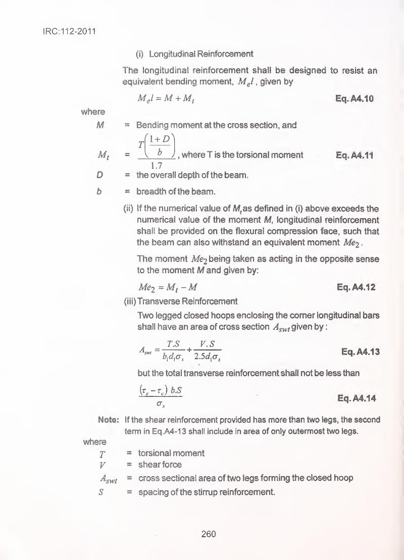
IRC:112-2011
(i) Longitudinal Reinforcement
The longitudinal reinforcement shall be designed to resist an
equivalent bending moment, MJ ,given by
where
M = Bending moment at the cross section, and
[ b J , whereT is the torsional moment Eq. A4.11
1.7
0 = the overall depth of the beam.
b = breadth of the beam.
(ii) If the numerical value of M^as defined in (i) above exceeds the
numerical value of the moment M, longitudinal reinforcement
shall be provided on the flexural compression face, such that
the beam can also withstand an equivalent moment Mej .
The moment Afe2 being taken as acting in the opposite sense
to the moment M and given by:
Me2 = Mf~M Eq.A4.12
(III) transverse Reinforcement
Two legged closed hoops enclosing the comer longitudinal bars
shall have an area of cross section ^4^, given by
:
. _ T.S V.S
but the total transverse reinforcement shall not be less than
- Eq.A4.14
Note: If the shear reinforcement provided has more than two legs, the second
term in Eq.A4-13 shall include In area of only outermost two legs.
where
T = torsional moment
V = shear force
^swt = cross sectional area of two legs fomiing the closed hoop
S = spacing of the stirmp reinforcement.
260
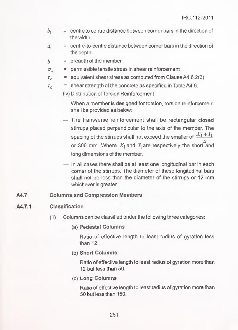
IRC:112-2011
bi = centre to centre distance between comer bars in the direction of
the width.
= centre-to-centre distance between corner bars in the direction of
the depth.
b = breadth of the member.
ag = permissible tensile stress in shear reinforcement
- equivalent shear stress as computed from Clause A4.6.2(3)
= shear strength of the concrete as specified in Table A4.6.
(iv) Distribution of Torsion Reinforcement
When a member is designed for torsion, torsion reinforcement
shall be provided as below:
— The transverse reinforcement shall be rectangular closed
stirrups placed perpendicular to the axis of the member. The
' spacing of the stirrups shall not exceed the smaller of —l —I4
or 300 mm. Where X| and Fj are respectively the short and
long dimensions of the member.
— In all cases there shall be at least one longitudinal bar in each
corner of the stirrups. The diameter of these longitudinal bars
shall not be less than the diameter of the stirrups or 12 mmwhichever is greater.
A4.7 Columns and Compression Members
A4.7.1 Classification
(1 ) Columns can be classified under the following three categories:
(a) Pedestal Columns
Ratio of effective length to least radius of gyration less
than 12.
(b) Short Columns
Ratio of effective length to least radius of gyration more than
12 but less than 50.
(c) Long Columns
Ratio of effective length to least radius of gyration more than
50 but less than 150.
261
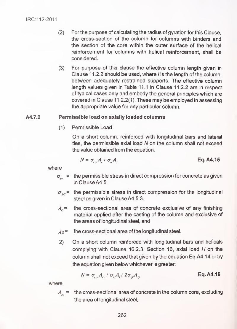
IRC:112-2011
(2) For the purpose of calculating the radius of gyration for this Clause,
the cross-section of the column for columns with binders and
the section of the core within the outer surface of the helical
reinforcement for columns with helical reinforcement, shall be
considered.
(3) For purpose of this clause the effective column length given in
Clause 11.2.2 should be used, where / is the length of the column,
between adequately restrained supports. The effective column
length values given in Table 11.1 in Clause 11.2.2 are in respect
of typical cases only and embody the general principles which are
covered in Clause 11.2.2(1). These may be employed in assessing
the appropriate value for any particular column.
A4.7.2 Permissible load on axially loaded columns
(1) Permissible Load
On a short column, reinforced with longitudinal bars and lateral
ties, the permissible axial load N on the column shall not exceed
the value obtained from the equation.
N=a A+G A Eq.A4.15CO c sc s '
where
= the permissible stress in direct compression for concrete as given
in Clause A4. 5.
cr^^= the permissible stress in direct compression for the longitudinal
steel as given in Clause A4. 5. 3.
the cross-sectional area of concrete exclusive of any finishing
material applied after the casting of the column and exclusive of
the areas of longitudinal steel, and
As = the cross-sectional area of the longitudinal steel.
2) On a short column reinforced with longitudinal bars and helicals
complying with Clause 16.2.3, Section 16, axial load / / on the
column shall not exceed that given by the equation Eq.A4 14 or by
the equation given below whichever is greater:
iV= o- .A -i- (J A -h 2(7 A Eq.A4.16
where
A^^^ = the cross-sectional area of concrete in the column core, excluding
the area of longitudinal steel,
262
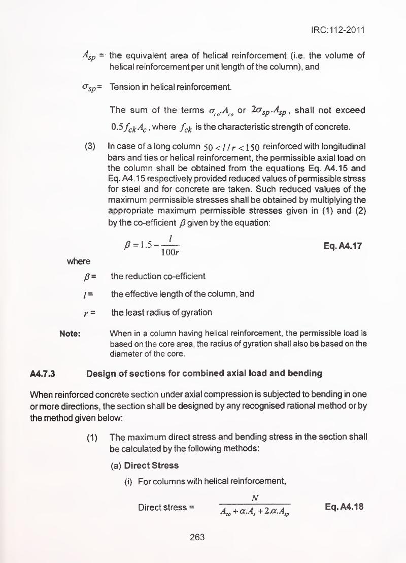
IRC:112-2011
Asp = the equivalent area of helical reinforcement (i.e. the volume of
helical reinforcement per unit length of the column), and
<^sp- Tension in helical reinforcement.
The sum of the terms or la^p.A^p, shall not exceed
0.5fck^c , where f^i^ is the characteristic strength of concrete.
(3) In case of a long column 50 < / / r < 1 50 reinforced with longitudinal
bars and ties or helical reinforcement, the permissible axial load onthe column shall be obtained from the equations Eq. A4.15 andEq. A4. 1 5 respectively provided reduced values of permissible stress
for steel and for concrete are taken. Such reduced values of the
maximum permissible stresses shall be obtained by multiplying the
appropriate maximum permissible stresses given in (1) and (2)
by the co-efficient J3 given by the equation:
^ = 1.5-^ Eq.A4.17
where
fi= the reduction co-efficient
/ = the effective length of the column, and
r = the least radius of gyration
Note: When in a column having helical reinforcement, the permissible load is
based on the core area, the radius of gyration shall also be based on the
diameter of the core.
A4.7.3 Design of sections for combined axial load and bending
When reinforced concrete section under axial compression is subjected to bending in one
or more directions, the section shall be designed by any recognised rational method or by
the method given below:
(1) The maximum direct stress and bending stress in the section shall
be calcu lated by the following methods:
(a) Direct Stress
(i) For columns with helical reinforcement,
NDirectstress=
A,„ + a.A^+2.a.A^ Eq.A4.18
263
IRC:112-2011
(ii) For columns with transverse reinforcement other than that
In (i) aboveN
Direct stress = A^+a.A^p Eq.A4.19
M(b) Bending Stress = ± -7 Eq,M2Q
where^
N = the load on the coluinn in the direction of its axis,
Ac = the area of concrete section perpendicular to the axis of the
c»lumn
a = the modular ratio,
W = the section modulus (In case of bending in two directions, W^is
the section modulus with reference to the appropriate principal
axis for two-way bending), and
M = moment about a principal axis.
In case of rectangular section subjected to bending in twoMdirections, the expression —- in the Eq.A4.19 can be substitutedwby
where
Mj( and My are the bending moments about two principal axis of the
section and Wy and are the conresponding section moduli.
(2) If the direct and the bending stresses, calculated as per (1) above
satisfy all the following conditions, the section may be considered
safe:
a.,cal a,.,cal,—
—
+—— >1(a)-;—+^->i.
Eq.A4.22CO ^ c
where
Geo y cal = the calculated direct compressive stress,
= the permissible direct compressive stress according to Clause
A4.5; multiplied by the reduction factor given by Eq. A4.16.
Gc , cal - the calculated flexural compressive stress, and
Gc ~ the permissible flexural compressive stress, according to Clause
A4.5, multiplied by the reduction co-efficient given by Eq. A4.17.
264
IRC:112-2011
(b) The resultant tension due to direct compression and flexure is
not greater than the value specified in Table A4.2 for the
appropriate grade of concrete.
(3) If the condition given in 2(ii) above is not satisfied, the section shall
be deemed to have cracked in the region of tension and the tensile
resistance of concrete is ignored altogether. The maximum stresses
in concrete and steel shall then be found according to the recognised
theory of cracked section. The fibre compressive stress in concrete
shall not exceed the values given for flexural compressive stress
as given in Table and those for tension in steel shall not exceed the
permissible stress in reinforcement given in Table A4. 3.
A4.8 Requirement for Prestressed Concrete Members
A4.8.1 General
This covers prestressed concrete members (post-tensioned determinate structures),
wherein adequate magnitude of prestressing force is applied to member in order to improve
the effective resistance of concrete to tensile forces arising from the loading effects at
working load levels. The working loads shall be as per IRC:6 (Table 1). For the purpose of
analysis, effective prestressing force is considered as load. For calculation of effective
prestressing force, the losses in prestressing force at various stages shall be calculated
as per Section 7 of this Code. While calculating the ultimate resistance of member, the
remaining capacity of bonded prestressing steel is considered to contribute to the ultimate
resistance. For unbonded tendons, the additional increase in forces if any shall be
neglected.
A4.8.2 Loads and forces
(1) The loads and forces and load combinations as per IRC:6 and as
applicable for the given structure shall be duly accounted for.
(2) All critical loading stages shall be investigated. The stages stated
below may normally be investigated:
(a) Stage Prestressing
Stage prestressing is permissible. The number of stages of
prestressing and grouting shall be reduced to the minimum,
preferably not more than two. However, concrete shall have
attained strength of not less than 20 MPa before any
prestressing is applied.
265
(b) Construction stages including temporary loading, transport,
handling and erection or any occasional loads that may occur
during launching of girders, etc., including impact, if any;
(c) The design loads are as per load combination given in (1 ) above
including the following discrete stages:
(i) Service Dead Load + Prestress with full losses.
(ii) Service Dead Load + Live Load + Prestress with full losses.
(d) For the combination of loads with differential temperature
gradient effects, maximum 50 percent live load shall beconsidered and any tensile stresses shall be taken care of by
providing adequately designed untensioned steel subject to the
crack width limitations stipulated in Clause 12.3.2 of the Code.
This shall apply notwithstanding the provision contained in
Clause A4.8.3(2). However, in the case of precast segmental
construction no tension shall be permitted under this load
combination.
(e) Ultimate load, as per Section 8 of this Code.
Permissible stresses in concrete
(1) Permissible temporary stresses in concrete
(a) These stresses are calculated after accounting for all appropriate
losses, pertaining to the stage of construction.
(b) The compressive stress produced due to loading mentioned in
Clause A 4.8.2 (b) shall not exceed 0.5 f^. where f^^ is the
concrete strength at that time subject to a maximum of 30 MPa.
(c) At full transfer the cube strength of concrete shall not be less
than 0.8 y^.^ . Temporary compressive stress in the extreme
fibre of concrete (including stage prestressing), shall not exceed
0.5^^ subject to maximum of 30 MPa.
(d) The temporary tensile stress in the extreme fibres of concrete
shall not exceed 1/1 0*^ of the permissible temporary compressive
stress in the concrete.
(2) Permissible stress in concrete during service
(a) The compressive stress in concrete under service loads shall
not exceed 0.33/^.
(b) No tensile stress shall be permitted in the concrete during
service.
266

IRC:112-2011
(c) If precast segmental elements are joined by prestressing, the
stresses in the extreme fibres of concrete during service shall
always be compressive and the minimum compressive stress
in an extreme fibre shall not be less than five per cent of
maximum permanent compressive stress that may be developed
in the same section. This provision shall not, however, apply to
cross prestressed deck slabs.,
;
(3) Permissible stresses in prestressing steel
Maximum jack pressure shay hot exceed 90 percent of 0. 1 percent
proof stress. For the purpose of this Clause, 0.1*percent proof stress
shall be taken as equal to 85 percent of minimum Ultimate Tensile
Strength (UTS).
Section properties
(1) For members consisting of precast as well as cast-in-situ units,
due consideration shall be given to the different moduli of elasticity
of concrete in the precast and cast-in-situ portions.
(2) For the purpose of determining the flexural stresses both prior to
and after grouting of the cables or tendons, the properties of the
section such as area, position of centroid and moment of inertia
may be based upon the full section of the concrete without deducting
the area of longitudinal openings left in the concrete for
prestressing tendons, cable ducts or sheaths. No allowance for the
transformed area of the prestressing tendons shall, however, be
made.
Deduction shall be made for the holes of transverse prestressing
tendons at sections where they occur, for determining the stresses
before grouting of these holes.
Ultimate strength
Prestressed Concrete Structural members shall be checked for
failure conditions at an ultimate load combination as specified by
IRC:6, Annexure-B, using methods given in Section 8 to
Section 11 of this Code.
Requirements of Minimum Dimensions of Members and MinimumReinforcement
The limits prescribed elsewhere in this code (detailing Sections)
shall be observed for design based on WL/AS method also.
267
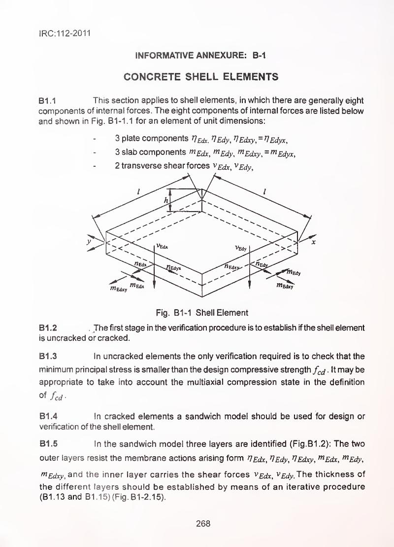
IRC:112-2011
INFORMATIVE ANNEXURE: B-1
CONCRETE SHELL ELEMENTS
B1 .1 This section applies to shell elements, in which there are generally eight
components of internal forces. The eight components of internal forces are listed below
and shown in Fig. B1-1.1 for an element of unit dimensions:
3 plate components rj^^ rjEdy, VEdxy, = lEdyx,
3 slab components m^dx, ^Edy, ^Edxy, = ^Edyx,
2 transverse shear forces VEdx, ^Edy,
Fig. B1-1 Shell Element
B1 .2 , The first stage in the verification procedure is to establish ifthe shell element
is uncracked or cracked.
B1 .3 In uncracked elements the only verification required is to check that the
minimum principal stress is smallerthan the design compressive strength f^^ . It may be
appropriate to take into account the multiaxial compression state in the definition
o^fcd-
B1.4 In cracked elements a sandwich model should be used for design or
verification of the shell element.
B1.6 in the sandwich model three layers are identified (Fig.B1.2): The two
outer layers resist the membrane actions arising form ^^atc, ^Edy, ^Edxy, ^Edx, ^Edy,
^Edxy, and the inner layer carries the shear forces V£^^ ^Edy. The thickness of
the different layers should be established by means of an iterative procedure
(B1.13 and B1.15)(Fig. B1-2.15).
268
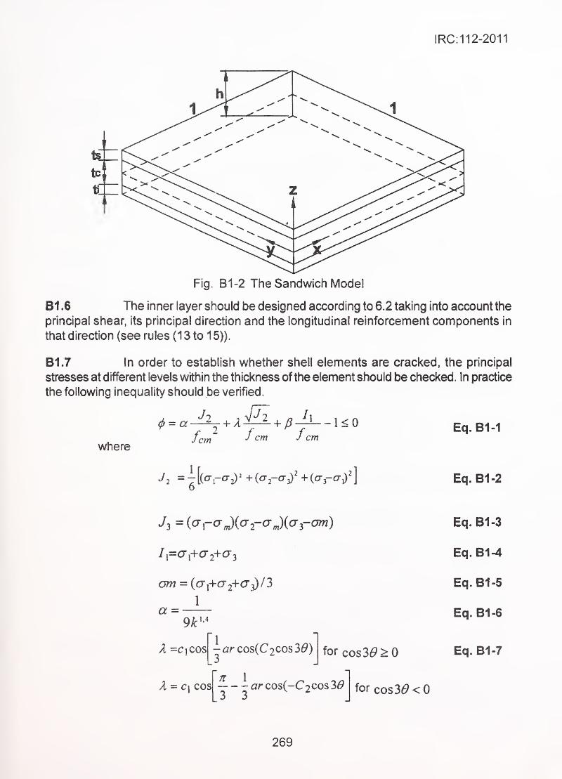
IRC:112-2011
Fig. B1-2 The Sandwich Model
B1 .6 The inner layer should be designed according to 6.2 taking into account the
principal shear, its principal direction and the longitudinal reinforcement components in
that direction (see rules (1 3 to 1 5)).
B1.7 in order to establish whether shell elements are cracked, the principal
stresses at different levels within the thickness of the element should be checked. In practice
the following inequality should be verified
.
where
= aJ
fc
2 ^x&^P-^~\<cm fcm fcm
Jl =7[(cr-0-2)= +(<T2-0-3)^+(cr3-Or^2]o
Eq. B1-1
Eq. B1-2
J3 =(<jraJ(a2-<jJ((73-o7w)
/,=c7,+a- 2+0-3
am = ((j,+cr2+cj3)/
3
1
a =9k 1.4
X =C|Cos
X-c\ cos
\^ar cos(C2Cos3^)
71 1
ar cos(-CoCOS 163 3
^
for cos36'>0
for cos3(9<0
Eq. B1-3
Eq. B1-4
Eq. B1-5
Eq. B1-6
Eq. B1-7
269
IRC:112-2011
Eq. B1^
cos 30 = 32 I
j72 Eq. B1-9
1
oj .Eq. B1-10
C2=l~6,8(i5:-0,07)V Eq. B1-11
^ = 4^. Eq. 81-12/ cm
If inequality in Eq. B1 .1 is satisfied, then the element is considered to be
uncracked; othenwise it should be considered as cracked.
81.8 If the shell element is considered to be cracked, the forces within the
outer layers of the sandwich model should be determined according to the following
equations (Fig. B1-3 and B1-4)
f^Edxs^^Edx——^ + —, Eq. 81-13
^X ^x
^x-yxi ^Edx ^^Edxi- ^Edx Eq. 81-14
^x
^Edys= ^Edy—
" + •—— Eq. 81-15y y
Zy-yyi ^EdynEdyr^Edy-——' — Eq. 81-16
y y
^yx~yyxs ^Edyx^Edyxs^^Edyx—;
; Eq. 81-17^yx ^yx
^yx-yyxi ^Edyx^Edyxr^Edyx—— +
Eq. 81-18^ yx ^yx
^xy~yxys ^Edxy^Edxys=^Edxy +
Eq. 81-19'^xy ^xy
270
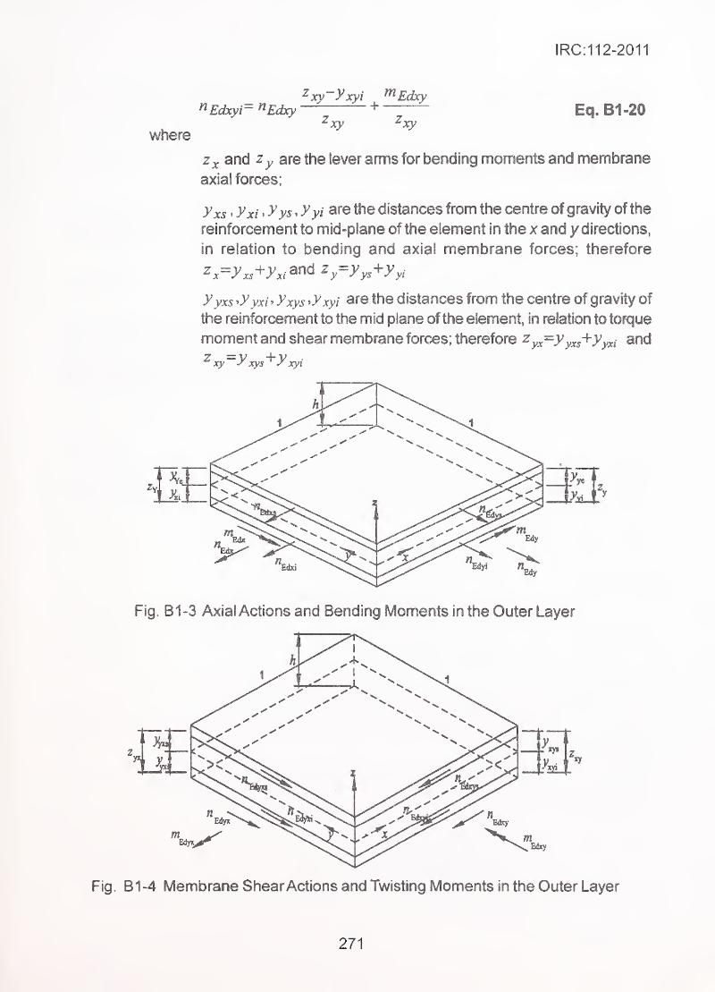
IRC:112-2011
^ Edxyr ^Edxy — +— Eq. B1 -20
where
Zx and Zy are the lever arms for bending moments and membrane
axial forces;
yxs > yxi > yys . yyi distances from the centre of gravity of the
reinforcement to mid-plane of the element m the x and y directions,
in relation to bending and axial membrane forces; therefore
, z.=yxs-^yxi^^^^y^yys^yyi
yyxs ^yyxi^yxys ^y xyi are the distances from the centre of gravity of
, the reinforcement to the mid plane of the element, in relation to torque
moment and shear membrane forces; therefore ^yx^yyxs^yyxi and
^xy~yxys'^y xyi'
Fig. B1 -3 Axial Actions and Bending Moments in the Outer Layer
Fig. B1-4 Membrane Shear Actions and Twisting Moments in the Outer Layer
271
IRC:112-2011
Out of plane shear forces v^^^^ and v^j^ are applied to the inner layer with the layer arm z^,
determined- with reference to the centroid of the appropriate layers of reinforcement.
B1.9 For the design of the inner layer the principal shear V£j^and its direction
(h" should be evaluated as follows:
_ L 2 , 2^Edo=i^Edx ^^Edy
_ , Eq. B1-21
B1 ,1 0 In the direction of principal shear the shell element behaves like a beamand the appropriate design rules should therefore be applied, in particular
Clause 1 0.3.2 should be applied for members not requiring shear reinforcement and Clause
10.3.3 should be applied for members requihng shear reinforcement. In expression 6.2a)
Pj should be taken as:
Pi = Px cos^ + py sin^ g}^ Eq. B1-23
81.11 When shear reinforcement is necessary, the longitudinal force resulting from
the truss model VEdo cot 0 gives rise to the following membrane forces in x and y directions:
2^Edy
riEdyc = — cot 6^ Eq. B1 -24
^Edo
^Edx^Edy^Edxyc
= —- cot 6> Eq. 81 -25^Edo "
.
.
^Edxc=^^^^^^^ ' Eq. 81-26
^Edx^Edy^£ifF.xc = "£J.n'c
= cot 6^ Eq. 81-27
81.12 The outer layers should be designed as membrane elements, using the
design rules of Section 9.
61.13 The following simplified approach may generally be adopted with respect
toFig. B1,3andB1.4.
ym = yxs = yys '. Eq. 81-28
yni = yxi = yyi' Eq. 81-29
272
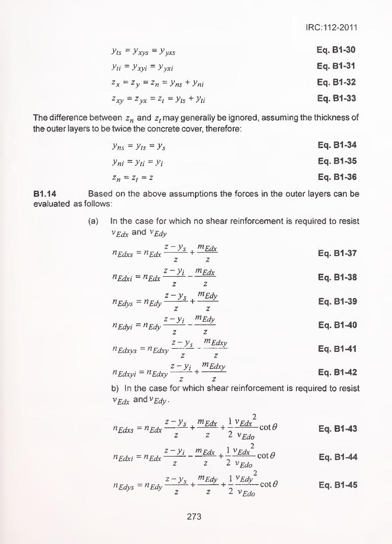
IRC:112-2011
yts^yxys^yyxs Eq.B1-30
yti'^yxyi'=yyxi Eq.Bi-3i
Zx=Zy^z^=yns^yni Eq. B1-32
^xy = ^yx = ^/ = yts + yti Eq. B1 -33
The difference between z„ and z^may generally be ignored, assuming the thickness of
the outer layers to be twice the concrete cover, therefore:
yns^yts'^ys Eq.B1-34
yni'^yti^yi Eq. B1-35
z„=Zj^z Eq. B1-36
B1.14 Based on the above assumptions the forces in the outer layers can be
evaluated as follows:
(a) In the case for which no shear reinforcement is required to resist
^Edx and VEdy
^Edxs = ^Edx + Eq. B1-37z z
z-Vi mpdxnEdxi = ^Edx
~ — Eq.B1-38
z -3^5 ^^Edxz z
z -yi ^Edx
z z
z -ys ^^Edy
z z
z -yi ^Edy
riRdys = ^Edy ~ + ~ Eq. 81-39
z-Vi ^EdynEdyi^^Edy—^
'f'Eq. B1-40
z-ys ^Edxy ^ ^^Edxys = ^Edxy
—~ "— Eq. B1-41
z-Vj f^Edxy
^Edxy!=^Edxy—J- +—^ Eq. B1-42
b) In the case for which shear reinforcement is required to resist
^Edx andv£j_^.
t 2
^Edxs=^Edx + + r cot6/ Eq. B1-43
«£d!.Y/ = '^£d^ + cot 0 Eq. B1 -44z z 2 v^do
2z-y^ f^Edy X^Edy ^
nEdys=^Edy — + - + r =^cot^ Eq. 81-45z z I VEdo
273

IRC:112-2011
^Edyi-^Edy " + + " COte^^ z 2 v^^o
^Edxys = ^Edxy^ + + ^COt^
cot^
Eq. B1-46
Eq. B1-48z z 2 VEdo
If the verification in (B1.12) above is not satisfied, one of the followingB1.15
procedures should be followed
.
(a) increase the concrete cover and consequently reduce the
internalleverami;
(b) use different values for z„ and with > internal concrete
stresses should then be added vectorially;
(c) Increase the layer thickness to satisfy the concrete verification
and leave the reinforcement position unchanged. This will cause
the reinforcement to become eccentric in the layer; as a
consequence two internal bending moments arise, and these
should be in equilibrium within the shell element. In these
circumstances, the internal reinforcement become:
^Eds =^Eds h--^-b: + ^Edi
2 •
where^Edi ^^Eds^^Edr ^ Eds
Eq. 81-49
Eq. 81-60
/ ^and // are the thickness of top and bottom layers, respectively;
b \ is the distance from the external surface of the layer to the axis
of the reinforcement within the layer.
The internal layer should be checked for an additional out of the
plane shear corresponding to the force transfer between the layers
of reinforcement.
274
IRC:112-2011
INFORMATIVE ANNEXURE B-2
MECHANISMS OF DETERIORATION OF CONCRETESTRUCTURES
This Annexure gives description of the main deterioration mechanisms which may need to
be considered in design.
B2.1 " Corrosion of Reinforcement/Prestressing Tendons
In normal circumstances, the highly alkaline nature of concrete protects steel embeddedwithin it. The pH value of the pore solution in concrete is generally in the region of 1 2 to
14. The protection is afforded by the formation of a very thin, coherent layer of iron oxide
over the surface of the steel bar under such alkaline conditions. Steel protected in this way
is described as being in a passive state. Steel will not generally corrode in uncontaminated
concrete until the pH drops below 10. Two mechanisms, v\lhich can lead to the destruction
of this passive state, are:-
(1) Carbonation of Concrete
This is a reaction between carbon dioxide in the atmosphere and
the calcium hydroxide in the hyd rated cement matrix. This process
starts at the surface and wit-h time, penetrates slowly into the
concrete. The rate of penetration of carbonation into the concrete,
is the highest, where the relative humidity is in the range 50 to 70
percent. It is lower at higher humidities, being effectively zero at
100 percent. The rate is also lower at lower humidities, being
effectively zero at 0 percent humidity, because carbonation
can not take place without presence of water. The rate of carbonation
will be lower in good quality concrete as compared to that in poor
quality concerete. The rate of carbonation depends on the rate at
which carbon dioxide can diffuse into the concrete. This will decrease
with a decrease in the water/cement ratio. The effect of carbonation
is to reduce the alkalinity of the concrete surrounding the reinforcement
to a level where the natural protection is lost.
(2) The presence of Chlorides in Concrete
Chlorides have the capacity to destroy the passivity of steel locally,
even where the alkalinity remains high, giving rise to 'pitting
corrosion'. Chlorides may get into the concrete from various
sources, but the commonest are seawater in marine environments;
275
IRC:112-2011
chloride ions, if any, contained in the ingredients of concrete,
particularly the mix water; and de-icing chemicals on bridge decks
as used in colder climates. The rate of ingress of chloride into the
concrete depends upon the amount of chloride in the service
environment in contact with the concrete surface and on the quality
of the concrete.
Once the passivity of the steel has been destroyed, occurrence of
corrosion of steel requires only two things; sufficient moisture and
sufficient oxygen. It is found that these two requirements can act
against each other since, if the concrete is wet, oxygen cannot
penetrate and if it is dry, there is insufficient moisture for the reaction
to progress. As a result, the greatest risk of corrosion is in memberssubjected to alternate wetting and drying.
B2.2 Frost Attack
If saturated concrete is subjected to frequent freezing and thawing, the expansive effects
of ice formation will disrupt the concrete. The usual manifestations of frost damage are
surface spalling or the formation of closely spaced surface cracks. Concrete, which is
not close to being saturated, is not at risk from frost as the expansion that occurs on
freezing can be accommodated in the pores not filled with water. Except in a few areas in
colder regions of the country, frost attack may not pose a significant problem.
B2.3 Alkali-aggregate Reactions
There are two basic forms of reaction which occasionally occur and can damage concrete:
viz. - the alkali-silica reaction and the alkali-carbonate reaction. The alkali-silica reaction
is the more common in India. It is a reaction between the alkalis (sodium and potassium
salts) in the cement and certain forms of glassy or crypto-crystalline silica in the aggregate,
which results in the formation of a hygroscopic 'silica gel'. This gel expands when in contact
with water, resulting in the formation of cracks, which may be large (several millimeters
wide are not uncommon). In relatively unstressed and unreinforced concrete, these cracks
can fomn a random map' pattern. In other cases, the cracks will tend to form parallel to the
direction of compressive stress or reinforcement. The cracks are usually not deep, only
extending 50-70 mm into the section. Their effect on structural performance is not as great
as might be imagined from looking at the cracks. A reduction in the compressive and
tensile strengths and modulus of elasticity of the concrete occurs, but this is commonly not
more than about 20-30 percent.
In India, siliceous rocks like granite, granite gneiss and schist, quartzite and sandstone,
containing 'strained quartz' have been found to be reactive. The methods of evaluation are
276
IRC:112-2011
given in IS 2386. More refined methods of detection of reactivity of aggregates are being
evolved, for which, specialist literature may be consulted.
B2A Attack from Sulphates
In the presence of water, sulphate ions can react with the tricalcium aluminate component
of the cement. This reaction causes expansion, leading to cracking and eventual
disintegration of the concrete. The commonest source of sulphates is in the earth
surrounding foundations but other sources are sometimes significant. Seawater contains
significant amounts of sulphates in addition to chlorides. The severity of attack depends
on the concentration of sulphate ions in the soil and subsoil water and in the environment.
B2.5 Attack by Aggressive Chemicals
Effluents, vapours, fumes etc. from chemical and fertilizer industries can attack concrete,
leading to its disintegration. In case of a bridge structure being exposed to such harmful
chemicals due to proximity to such industries, the structure should be designed for
'extreme' exposure condition (Table 14.1). Protective coatings may be required. For further
guidance, specialist literature may be referred.
B2.6 Acid Attack
No concrete is acid resistant. Even mild acids (pH 4 to 5) can attack the calcium
compounds in concrete, converting them to soluble salts, which can then leach away. The
effect of acids is therefore to eat away, or render the surface of the concrete weak and
permeable. Acid rain, for example, will do no more than etch the surface of the concrete
over any reasonable design life. If the concrete is likely to be exposed to major amounts of
acid, for example from some industrial process, the only way to avoid damage is to provide
an impermeable coating to the concrete.
B2.7 Abrasion
Abrasion of concrete surfaces may occur due to movement of boulders, sand or gravel
suspended in turbulent water, or air borne sand particles. Resistance to abrasion can be
obtained by using higher strength concrete and abrasion resistant aggregates. Resistance
is also markedly improved by good curing of surfaces likely to be exposed to abrasive
action.
277
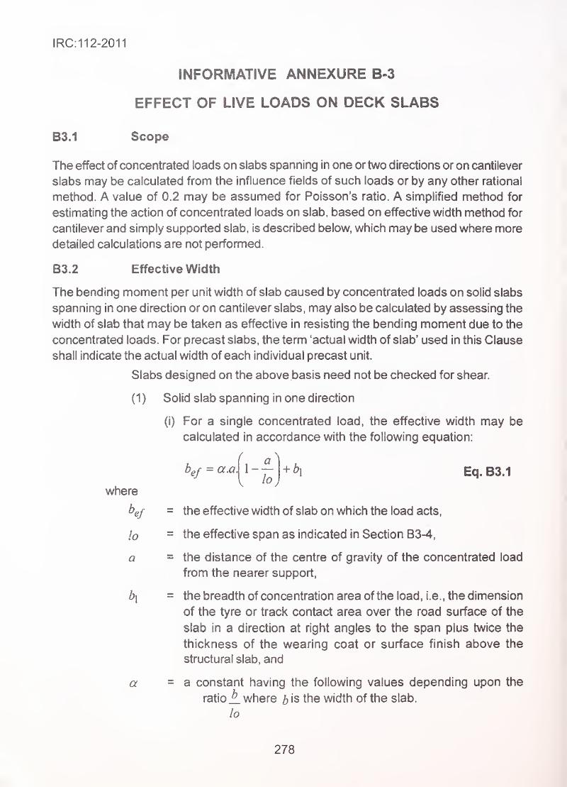
IRC:112-2011
INFORMATIVE ANNEXURE B-3
EFFECT OF LIVE LOADS ON DECK SLABS
B3.1 Scope
The effect of concentrated loads on slabs spanning in one or two directions or on cantilever
slabs may be calculated from the influence fields of such loads or by any other rational
method. A value of 0.2 may be assumed for Poisson's ratio. A simplified method for
estimating the action of concentrated loads on slab, based on effective width method for
cantilever and simply supported slab, is described below, which may be used where more
detailed calculations are not performed.
B3.2 Effective Width
The bending moment per unit width of slab caused by concentrated loads on solid slabs
spanning in one direction or on cantilever slabs, may also be calculated by assessing the
width of slab that may be taken as effective in resisting the bending moment due to the
concentrated loads. For precast slabs, the term 'actual width of slab' used in this Clause
shall indicate the actual width of each individual precast unit.
Slabs designed on the above basis need not be checked for shear.
(1) Solid slab spanning in one direction
(i) For a single concentrated load, the effective width may be
calculated in accordance with the following equation:
b^j = a.a. + b\ Eq. B3.1
where
be/ = the effective width of slab on which the load acts,
lo - the effective span as indicated in Section B3-4,
a = the distance of the centre of gravity of the concentrated load
from the nearer support,
b\ = the breadth of concentration area of the load, i.e., the dimension
of the tyre or track contact area over the road surface of the
slab in a direction at right angles to the span plus twice the
thickness of the wearing coat or surface finish above the
structural slab, and
a = a constant having the following values depending upon the
ratioA where b is the width of the slab.
lo
278
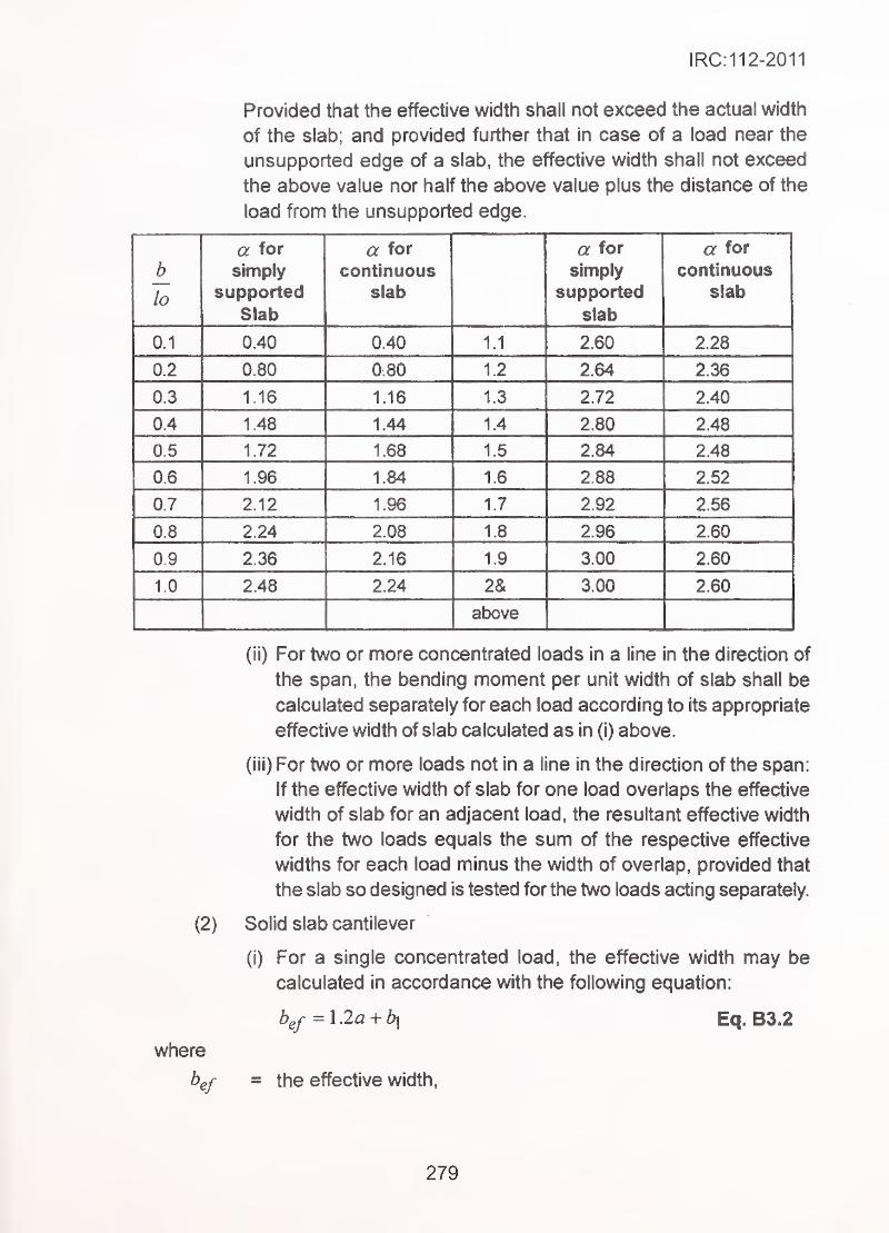
IRC:112-2011
Provided that the effective width shall not exceed the actual width
of the slab; and provided further that in case of a load near the
unsupported edge of a slab, the effective width shall not exceed
the above value nor half the above value plus the distance of the
load from the unsupported edge.
a for a for a for a for
b simply continuous simply continuous
losupported slab supported slab
Slab slab
0.1 0.40 0.40 1.1 2.60 2.28
0.2 0.80 0.80 1.2 2.64 2.36
1 16 1 1fi 11 .vJ 9 79 o An
0.4 1.48 1.44 1.4 2.80 2.48
0.5 1.72 1.68 1.5 2.84 2.48
0.6 1.96 1.84 1.6 2.88 2.52
0.7 2.12 1.96 1.7 2.92 2.56
0.8 2.24 2.08 1.8 2.96 2.60
0.9 2.36 2.16 1.9 3.00 2.60
10 2.48 2.24 2& 3.00 2.60
above
(ii) For two or more concentrated loads in a line in the direction of
the span, the bending moment per unit width of slab shall be
calculated separately for each load according to its appropriate
effective width of slab calculated as in (i) above.
(Hi) For two or more loads not in a line in the direction of the span:
If the effective width of slab for one load overlaps the effective
width of slab for an adjacent load, the resultant effective width
for the two loads equals the sum of the respective effective
widths for each load minus the width of overlap, provided that
the slab so designed is tested for the two loads acting separately.
(2) Solid slab cantilever
(i) For a single concentrated load, the effective width may be
calculated in accordance with the following equation:
b^f^Ma^bx Eq. B3.2
where
b^f = the effective width.
279
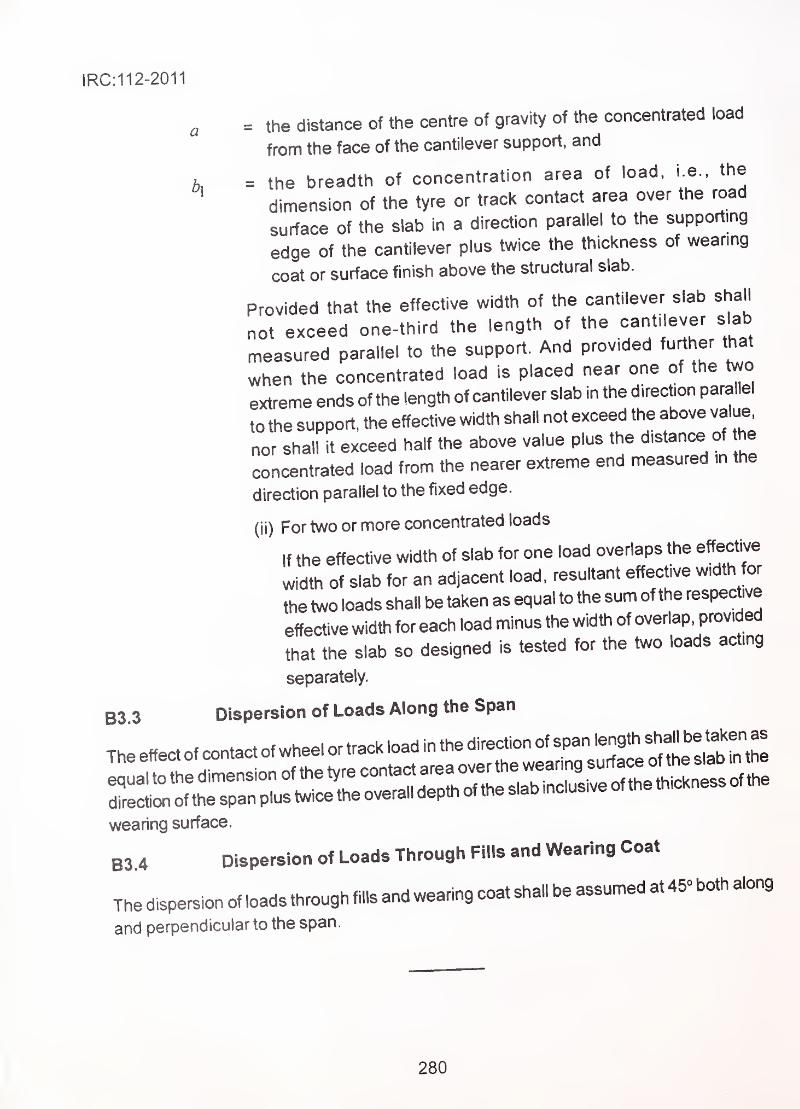
|RC:112-2011
a = the distance of the centre of gravity of the concentrated load
from the face of the cantilever support, and
K = the breadth of concentration area of load, i.e.. the
dimension of the tyre or track contact area over the road
surface of the slab in a direction parallel to the supporting
edge of the cantilever plus twice the thickness of weanng
coat or surface finish above the structural slab.
Provided that the effective width of the cantilever slab shall
not exceed one-third the length of the cantilever slab
measured parallel to the support. And provided further that
when the concentrated load is placed near one of the two
extreme ends of the length of cantilever slab in the direction parallel
to the support, the effective width shall not exceed the above value^
nor shall it exceed half the above value plus the distance of he
concentrated load from the nearer extreme end measured in the
direction parallel to the fixed edge,
(ii) For two or more concentrated loads
If the effective width of slab for one load overlaps the effective
width of slab for an adjacent load, resultant effective width for
the two loads shall be taken as equal to the sum of the respective
effective width for each load minus the width of overlap, provided
that the slab so designed is tested for the two loads acting
separately.
B3 3 Dispersion of Loads Along the Span
wearing surface.
B3.4 Dispersion of Loads Through Fills and wearing Coat
Thedispersionofloadsthroughfillsand wearingcoat shall be assumed at45"both along
and perpendicular to the span.
280


e Official amendments to this document which may be considered necessaryfrom time to time would be published by the IRC in its periodical 'Indian
Highway'. These shall be considered as effective and as part
of the Code etc. from the date specified therein)
Related Documents