Conceptualization and Multi-Objective Optimization of the Electric System of an Airborne Wind Turbine J. W. Kolar et al. Swiss Federal Institute of Technology (ETH) Zurich Power Electronic Systems Laboratory www.pes.ee.ethz.ch

Welcome message from author
This document is posted to help you gain knowledge. Please leave a comment to let me know what you think about it! Share it to your friends and learn new things together.
Transcript

1/63
Conceptualization and Multi-Objective Optimization of the Electric System of an
Airborne Wind Turbine
J. W. Kolar et al.
Swiss Federal Institute of Technology (ETH) Zurich Power Electronic Systems Laboratory
www.pes.ee.ethz.ch

2/63
Pareto-Optimal Design of Airborne Wind Turbine Power Electronics
J. W. Kolar, T. Friedli, F. Krismer, A. Looser, M. Schweizer, P. Steimer, J. Bevirt
Swiss Federal Institute of Technology (ETH) Zurich Power Electronic Systems Laboratory
www.pes.ee.ethz.ch

3/63
Outline
► Futuristic Wind Turbine Concepts ► Airborne Wind Turbine Electrical System ► Multi-Objective Optimization ► Controls Aspects ► Conclusions

4/63
Conventional 100kW Wind Turbine
► Characteristics
- Tower 35m/18 tons - Rotor 21m / 2.3tons - Nacelle 4.4 tons
■ Large Fraction of Mechanically Supporting Parts / High Costs
►

5/63
Revolutionize Wind Power Generation Using Kites / Tethered Airfoils
■ Wing Tips / Highest Speed Regions are the Main Power Generating Parts of a Wind Turbine
[2] M. Loyd, 1980

6/63
Controlled Power Kites for Capturing Wind Power
■ Wing Tips / Highest Speed Regions are the Main Power Generating Parts of a Wind Turbine
► Replace Blades by Power Kites ► Minimum Base Foundation etc. Required ► Operative Height Adjustable to Wind Conditions [2] M. Loyd, 1980

7/63
► Wind at High Altitudes is Faster and More Consistent ► Operate Kites at High Altitudes or Even in the Jet Stream
0
.
0
0
.
2
0
.
4
0
.
6
0
.
8
1
.
0
1
.
2
1
.
4
1
.
6
1
.
8
2
.
0
120m
2 kW/m2 0
700m
Source:
Controlled Power Kites for Capturing Wind Power

8/63
Controlled Power Kites for Capturing Wind Power
► Wind at High Altitudes is Faster and More Consistent ► Operate Kites at High Altitudes or Even in the Jet Stream

9/63
Pumping Power Kites
■ Generated Force Could be Converted into Useful Power by Pulling a Load / Driving Turbines via a Tether
► Kite´s Aerodynamic Surface Converts Wind Energy into Kite Motion
Source: M. Diehl / K.U. Leuven
►
►

10/63
Pumping Power Kites
► Maximum Power
Source: M. Diehl / K.U. Leuven
[2] M. Loyd, 1980

11/63
Pumping Power Kites for Capturing High Altitude Wind Power
► Lower Electricity Production Costs than Current Wind Farms ► Generate up to 250 MW/km2, vs. the Current 3 MW/km2
► Research at the

12/63
Pumping Power Kites for Capturing High Altitude Wind Power
Carousel Configuration
► Lower Electricity Production Costs than Current Wind Farms ► Generate up to 250 MW/km2, vs. the Current 3 MW/km2
► Research at the

13/63
Alternative Concept – Airborne Wind Turbine
► Power Kite Equipped with Turbine / Generator / Power Electronics ► Power Transmitted to Ground Electrically [2] M. Loyd, 1980
►

14/63
Alternative Concept – Airborne Wind Turbine
► Power Kite Equipped with Turbine / Generator / Power Electronics ► Power Transmitted to Ground Electrically
Source:
[2] M. Loyd, 1980

15/63
Basic Physics of Wind Turbines
► Maximum Achievable acc. to Lanchester / Betz ► High Crosswind Kite Speed Very Small Turbine Area
►

16/63
Comparison of Conventional / Airborne Wind Turbine
■ Numerical Values Given for 100kW Rated Power
17/63
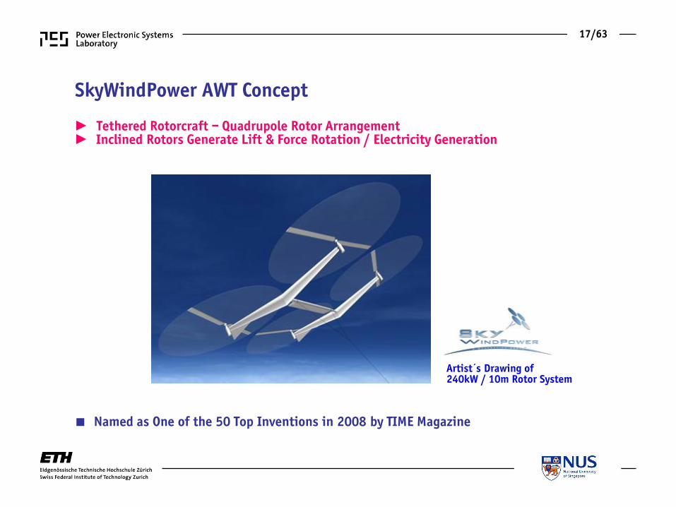
SkyWindPower AWT Concept
► Tethered Rotorcraft – Quadrupole Rotor Arrangement ► Inclined Rotors Generate Lift & Force Rotation / Electricity Generation
Artist´s Drawing of 240kW / 10m Rotor System
■ Named as One of the 50 Top Inventions in 2008 by TIME Magazine

18/63
► Reinforced Tether Transfers MV-Electricity to Ground ► Composite Tether also Provides Mechanical Connection to Ground
AWT Concept

19/63
AWT Basic Electrical System Structure
► Rated Power 100kW ► Operating Height 800…1000m ► Ambient Temp. 40°C ► Power Flow Motor & Generator
■ El. System Target Weight 100kg ■ Efficiency (incl. Tether) 90% ■ Turbine /Motor 2000/3000rpm

20/63
Design of Electrical Power System
► Clarify Practical Feasibility of AWT Concept ► Clarify Weight/Efficiency Trade-off / Multi-Objective Optimization / Pareto-Front

21/63
Tether Design DC Voltage Level η-γ-Pareto Front

22/63
Tether DC Transmission Voltage Level
► Pth,1 = 100kW / lth = 1000m ► Strain Relief Core – Kevlar (Fth = 70kN, d=5mm) ► Cu or Al Helical Conductors - ½ Uth Isolated ► Outer Protection Jacket (3mm)

23/63
► Tether Voltage Vth,1 = 8kV
Tether η-γ-Pareto Front
■ Total Weight of Tether: 320kg
24/63
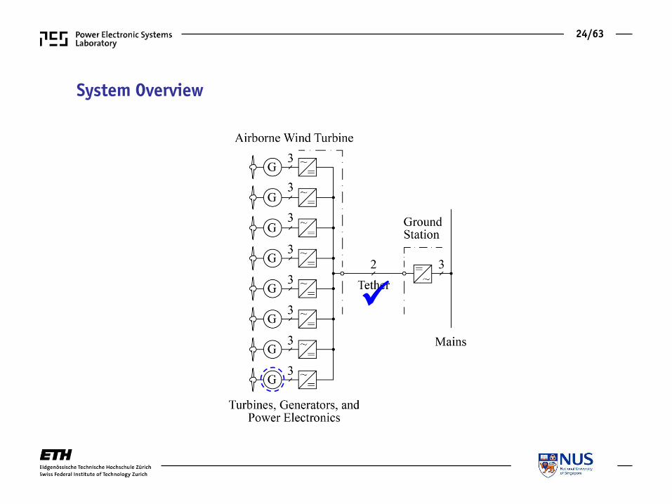
System Overview

25/63
Possible AWT Electrical System Structures
►
►
► Low-Voltage or Medium-Voltage Generators / Power Electronics ► Decision Based on Weight/Efficiency/Complexity

26/63
Generator / Motor Design Dimensions
Number of Pole Pairs η-γ-Pareto Front

27/63
Generator / Motor η-γ-Pareto Front
► Medium Voltage vs. Low Voltage Machine Vth,1 = 8kV
■ LVG: Diameter 17cm (excl. Cooling Fins) / Width 6.0cm / p = 20 / η = 95.4% / Weight 5.1kg
- PMSM – Radial Flux – Internal Rotor - Slotted Stator / Concentrated Windings – Air Cooling - Analytical EM and Thermal Models for Weight / Efficiency Optimization - P = 16kW / 2000rpm
LV Machine HV Machine Thermal Model

28/63
CAD Drawing of LV and MV Machine
► Fixed Parameters and Degrees of Freedom

29/63
Generator / Motor η-γ-Pareto Front
► Selected Design
η = 95.4% γ = 3.1 kW/kg
■ Medium Voltage Machine Not Considered Further

30/63
► Motors Employed for Electric Propulsion of Glider Airplane
Comparison to Commercial Motors
■ Diameter 22cm Width 8.6cm Weight 12kg Pole Pairs 10 Efficiency 91%
Power P = 10kW Speed n = 2200rpm Cooling vL = 25m/s

31/63
System Overview

32/63
Rectifier / Inverter Design Chip Area
Heatsink Volume η-γ-Pareto Front

33/63
Rectifier / Inverter Design
► 2-Level or 3-Level Bidirectional Voltage Source Rectifier
■ Maximization of Heatsink Thermal Conductance / Weight (Volume) - Max. CSPI
- S = 19.3kVA - VDC = 750V - fS,min= 24kHz - TJ = 125°C - Foil Capacitor DC Link
1200V T&FS Si IGBT4s / 1200V SiC Diodes
600V T&FS Si IGBT3s / 600V Si EmCon3 Diodes

34/63
VF [m3/s]
p
F [
N/m
2]
k . pFoperatingpoint
b/n
n = 5
s
d
c
b
PV
pCHANNEL
t
pF,MAX
VF,MAX
Heatsink Optimization
■ Highest Performance Fan ■ Fin Thickness / Channel Width Optimization
VF [m3/s]
p
F [
N/m
2]
k . pFoperatingpoint
b/n
n = 5
s
d
c
b
PV
pCHANNEL
t
pF,MAX
VF,MAX
► Maximize Thermal Conductance / Weight (Volume)
vAir ≈ 5m/s

35/63
Heatsink Optimization
PV /n
Rth,d
Rth,a
Rth,A Rth,A
s
t
c/2
d
Rth,FINRth,FIN
TCHANNEL
VF [m3/s]
p
F [
N/m
2]
k . pFoperatingpoint
b/n
n = 5
s
d
c
b
PV
pCHANNEL
t
pF,MAX
VF,MAX
► Maximize Thermal Conductance / Weight (Volume)
■ Highest Performance Fan ■ Fin Thickness / Channel Width Optimization

36/63
0 0.2 0.4 0.6 0.8 1k = s/(b/n)
0
0.2
0.4
0.6
0.8
1
Rth [
K/W
]
n=6
n=50
XX
n=10
n=34
optimum: n=26 / k=0.65 s=1.0mm / t=0.54mmRth,sub=0.26
sub-optimum: n=16 / k=0.60 s=1.5mm / t=1.0mmRth,sub=0.30
L x b x c= 80x40x40mm3
Al with th= 210W/Km
n = [6, 10, 14, ...., 42, 46, 50]
■ Highest Performance Fan ■ Fin Thickness / Channel Width Optimization
Heatsink Optimization
► Optimum

37/63
Rectifier / Inverter η-γ-Pareto Front
► Selected Design
η = 98.5% γ = 19 kW/kg
■ 3-Level Topology Does Not Show a Benefit
- Switching Frequency Range 24…70 kHz - Heatsink Temperature Range 55…100 °C (Tamb = 40°C)

38/63
System Overview

39/63
8kVDC/750VDC DAB Converter Design Switches / Topology
Transformer η-γ-Pareto Front
40/63
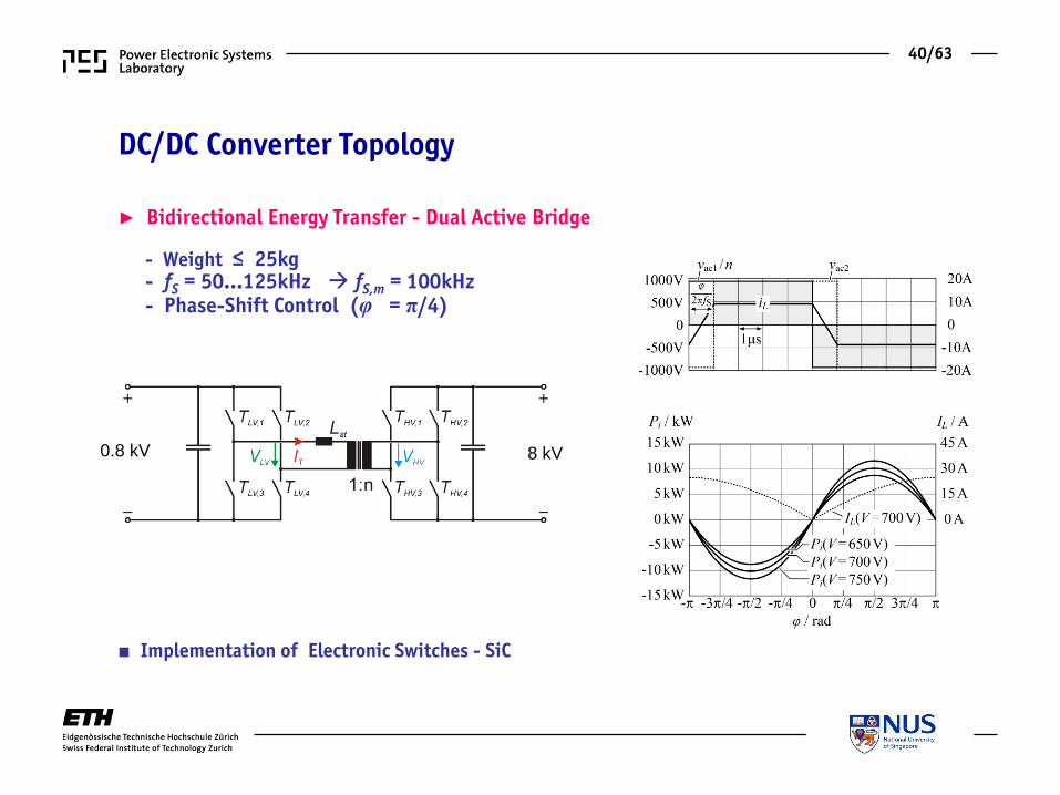
DC/DC Converter Topology
► Bidirectional Energy Transfer - Dual Active Bridge
0.8 kV 8 kV
■ Implementation of Electronic Switches - SiC
- Weight ≤ 25kg - fS = 50…125kHz fS,m = 100kHz - Phase-Shift Control (φ = π/4)

41/63
DC/DC Converter Topology
0.8 kV 8 kV
■ Implementation of Electronic Switches - SiC
► 10kV Si/SiC SuperCascode Switch
- Weight ≤ 25kg - fS = 50…125kHz fS,m = 100kHz - Phase-Shift Control (φ = π/4)
► Bidirectional Energy Transfer - Dual Active Bridge
42/63
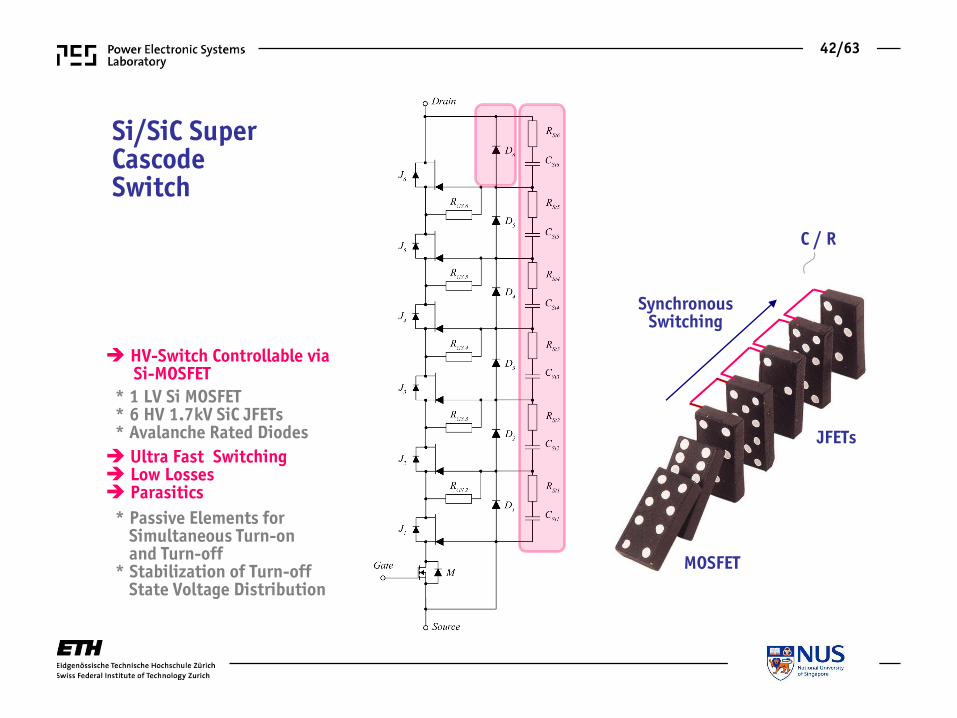
Si/SiC Super Cascode Switch
HV-Switch Controllable via Si-MOSFET
* 1 LV Si MOSFET * 6 HV 1.7kV SiC JFETs * Avalanche Rated Diodes
Ultra Fast Switching Low Losses Parasitics
* Passive Elements for Simultaneous Turn-on and Turn-off * Stabilization of Turn-off State Voltage Distribution
Synchronous Switching
MOSFET
JFETs
C / R

43/63
Si/SiC Super Cascode Switch
HV-Switch Controllable via Si-MOSFET
* 1 LV Si MOSFET * 6 HV 1.7kV SiC JFETs * Avalanche Rated Diodes
Ultra Fast Switching Low Losses Parasitics
* Passive Elements for Simultaneous Turn-on and Turn-off * Stabilization of Turn-off State Voltage Distribution
Synchronous Switching
MOSFET
JFETs
C / R

44/63
Selected Multi-Cell Converter Topology
Pi = 6.25kW Vth,1,i = 2kV
► MV-Side Series-Connection / LV-Side Parallel-Connection
■ Winding Arrangement & Efficiency / Weight Optimization of Transformer

45/63
Transformer Design
► MV-Winding Arranged Around Inductor Cores ► Cooling Provided by Heatpipes ► Stacked Cores - Scalable Arrangement
■ Optimization - Weight / Efficiency Trade-off

46/63
Transformer Optimization
► Degrees of Freedom / Parameter Ranges

47/63
Transformer η-γ-Pareto Front
► Selected Design
η = 97% γ = 4.5 kW/kg
■ Transformer Volt-Second Balancing - Series Capacitor or “Magnetic Ear” Control

48/63
Transformer Volt-Second Balancing – “Magnetic Ear”
► Magnetic Ear Magnetized with 50% Duty Cycle Rectangular Voltage Winding ► Measured Aux. Current iaux / Voltage vm Indicates Flux Level ► Enables Closed-Loop Flux Control
N27 E55 Ferrite

49/63
System Overview
50/63
Overall System Consideration Total Weight
Overall Efficiency η-γ-Pareto Front

51/63
Determination of Overall System Performance
► Consideration of the η-γ-Characteristics of the Partial Systems
■ Efficiencies of the Partial Systems Need to be Taken into Account ■ PD/PR = Overrating Ratio (8x16kW/100kW)
► Overall η-γ-Characteristic outP
m

52/63
Overall System Performance
■ Final Step: System Control Consideration
►

53/63
Electric System Control Stability
Reference Response Disturbance Response

54/63
System Control
► Control of Flight Trajectory / Max. Energy Generation ► Generator (Motor) Speed / Torque Control ► etc. ► Control of DC Voltage Levels is Mandatory !
■ Simplified Control-Oriented Block Diagram of the Electric System

55/63
Control Block Diagram
► Ground Station Controls the Tether Voltage ► Control Objectives: LV DC Bus 650…750V; MV (Tether) < 8kV
■ Only Tether Voltage at Ground Station is Measured (ITh Feedforward) ■ Motor AND Generator Operation Must be Considered

56/63
Tether Voltage Control Plant ►
►
Motor Operation (100kW)
57/63
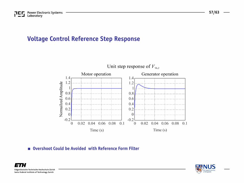
Voltage Control Reference Step Response
■ Overshoot Could be Avoided with Reference Form Filter

58/63
Voltage Control Disturbance Response
■ Motor Operation 100kW 0 ■ Gen. Operation ─100kW 0

59/63
► AWTs are Basically Technically Feasible ► AWTs Realization Combines Numerous Challenges - Aircraft Design - MVDC Transmission - MV/HF Power Electronics - etc. ► AWTs are a Highly Interesting Example for η-γ Trade-off Studies ► AWTs are Examples for Smart Pico Grids or MEA Power System Analysis ► AWTs Could Teach Students to Think “Out-of-the-Box”
Conclusions

60/63
Future Prospects
■ Example for Students to Think “Out-of-the-Box” !
Source: M. Diehl / K.U. Leuven

61/63
Future Prospects Future Prospects
■ Example for Students to Think “Out-of-the-Box” !
Source: M. Diehl / K.U. Leuven

62/63
Thank You!

63/63
Questions ?
Related Documents