ISSUED 24-Apr-08 CONSTRUCTION STANDARD ELECTRIC OPERATIONS ORGANIZATION C1100 Revision 0 Page 1 of 25 ****This Standard Supersedes BECo 2.10-2.1, COM/Elec NEFA**** DISTRIBUTION DUCTBANK CONSTRUCTION AND MATERIALS Table of Contents page 1) Scope ………………………………………………………………………….. 2 2) General ……………………………………………………………….……….. 2 3) Conduit & Fittings Specifications ………………………………………... 2 4) Conduit Plan and Records/Data Requirements …………………….... 2 5) Application …………………….…………………………………….………... 3 6) Excavation, Backfill and Street Restoration ……………………......... 3 - 4 7) Installation ……………………................................................................ 4 - 5 8) Breaking into existing Manholes ………………………………………... 6 9) Compatible Unit Format for Conduit & Fittings …………………….... 6 - 7 10) Ductbank Compatible Units ………………………………..……………….. 7 11) Bill of Materials/Compatible Units – Conduit, Fittings & Access. ….. 8 - 11 12) Typical Construction Plans (Figures A – G)…………….……………. 12 - 18 13) Duct Bank Cross Sections (Figures 1 – 23)…………….……………. 19 - 24 14) Conduit Bank Concrete Requirements and Weights/linear Ft. ……..... 25 15) Reference Standards ………………………………..………………………... 25 16) Signature Approval ………………………………..………………………...... 25

Welcome message from author
This document is posted to help you gain knowledge. Please leave a comment to let me know what you think about it! Share it to your friends and learn new things together.
Transcript

ISSUED
24-Apr-08
CONSTRUCTION STANDARD ELECTRIC OPERATIONS ORGANIZATION
C1100
Revision 0 Page 1 of 25
****This Standard Supersedes BECo 2.10-2.1, COM/Elec NEFA****
DISTRIBUTION DUCTBANK CONSTRUCTION AND MATERIALS
Table of Contents
page
1) Scope………………………………………………………………………….. 2
2) General……………………………………………………………….……….. 2
3) Conduit & Fittings Specifications………………………………………... 2
4) Conduit Plan and Records/Data Requirements …………………….... 2
5) Application…………………….…………………………………….………... 3 6) Excavation, Backfill and Street Restoration ……………………......... 3 - 4
7) Installation ……………………................................................................ 4 - 5 8) Breaking into existing Manholes………………………………………... 6
9) Compatible Unit Format for Conduit & Fittings …………………….... 6 - 7
10) Ductbank Compatible Units………………………………..……………….. 7
11) Bill of Materials/Compatible Units – Conduit, Fittings & Access. ….. 8 - 11
12) Typical Construction Plans (Figures A – G)…………….……………. 12 - 18
13) Duct Bank Cross Sections (Figures 1 – 23)…………….……………. 19 - 24
14) Conduit Bank Concrete Requirements and Weights/linear Ft. ……..... 25
15) Reference Standards………………………………..………………………... 25
16) Signature Approval………………………………..………………………...... 25
ISSUED
24-Apr-08
CONSTRUCTION STANDARD ELECTRIC OPERATIONS ORGANIZATION
C1100
Revision 0 Page 2 of 25
1.0 Scope
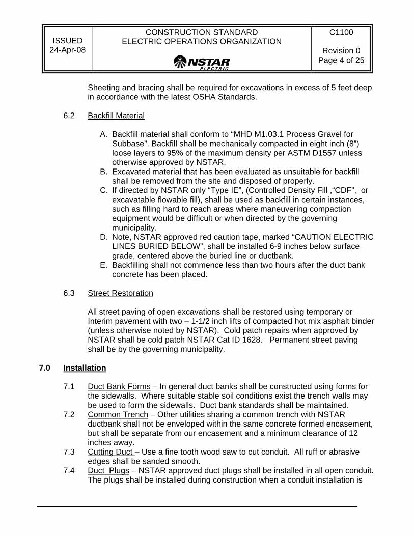
The purpose of this standard is to provide ductbank construction details, installation requirements and material lists for concrete-encased and direct buried conduit systems.
2.0 General
2.1 All excavation, backfill and paving shall be done In accordance with this standard and all applicable local and state regulations. When conflicts exist between local/state regulations and this standard the more stringent requirement shall be adhered to unless otherwise directed by NSTAR.
2.2 Before placing concrete within ductbank forms and backfilling an NSTAR inspection is required to ensure compliance with all referenced specifications.
2.3 DIG Safe marking and notification regulations are to be understood and adhered to during all construction.
2.4 All NSTAR safety standards as well as all applicable OSHA and DOT worker safety requirements shall be adhered to at all in times. Refer to NSTAR Work Method Standard, “W1000, Entering and Working in Underground Locations including Subsurface Vaults” specific requirements.
3.0 Conduit & Fittings Specifications
All encased conduit shall be PVC conduit (Type EB) and fittings shall be schedule 40 unless otherwise specified by NSTAR. Direct buried conduit and fittings shall be schedule 40 minimum. Refer to NSTAR Material Standard “M1000, PVC Conduit & Fittings” for details.
4.0 Conduit Plan and Records/Data Requirements 4.1 All proposed electric utility pans shall be approved by NSTAR local engineering
dept. before construction begins. New subdivision or commercial development plans to be submitted for local authority petitions (town approval) shall also be provided to NSTAR as AutoCAD data files. These shall show all proposed and existing utility plan view layers including electric, gas, water, sewer, drain, cable/data, telephone, and fire alarm.
4.2 The proposed electric utility plans shall include profile views that show relative elevation and clearances where proposed electric duct banks or lines intersect with non-electric utilities. Separation in any direction from electric to other utilities of 12" or less shall be detailed on the drawings.

ISSUED
24-Apr-08
CONSTRUCTION STANDARD ELECTRIC OPERATIONS ORGANIZATION
C1100
Revision 0 Page 3 of 25
4.3 GPS land based x-y-z coordinates shall be in NAD83 state plane feet format, with a minimum one foot accuracy. These plans shall show the road layout, curb lines, property lines (parcel boundaries), utility easements and utilities. Center coordinate positions shall be provided for all new manholes/pull boxes, equipment pads, and riser poles. Conduit location coordinates shall be provided at every 50 ft on straight sections or curves with less than 5 degree radii, and at every 20 ft for curves/sweeps over 5 degrees. GPS data for new conduit and infrastructure shall have accuracy of 6 inches or better.
4.4 Contractor shall provide NSTAR Survey and Records department (or local engineering) with as-built new facility location data in electronic file format within 20 business days of completing the project (CD or EFT). All files shall be labeled with the project title, town, NSTAR work order number and date of completion.
5.0 Application
5.1 Typically all primary and secondary distribution duct banks shall be unreinforced concrete encased using Type EB conduit. Stocked fittings are generally Schedule 40 unless otherwise specified.
5.2 If the interval between concrete pours for a continuous duct bank is expected to be more than 4 hours apart, industry standard construction joints shall be formed to ensure that the continuation of the ductbank pour shall create an interlocking joint between different pours. Refer to Figure “E” for detail.
5.3 The concrete specified for ductbanks shall be an approved 2500 psi pea stone mix using Type 2 Portland cement.
5.4 Reinforced distribution ductbanks maybe required per NSTAR for locations where ductbanks cross over other utilities and/or a future excavation could expose NSTAR ductbank without support. Reinforced ductbanks may also be required when installation is in soils that do not meet NSTAR specified backfill. For reinforced concrete ductbank standards refer to NSTAR Construction Standard, “C1101, Distribution Duct bank Construction, and (Steel Reinforced Concrete)”.
5.5 Exceptions to concrete encased ductbanks, i.e. direct buried conduit, may be allowed by NSTAR for secondary conduits installed off roadways and areas not subject to vehicle loads such as greenbelts and yards. Also when approved by NSTAR, single or double primary conduit runs in URD residential subdivisions may be direct buried as long as minimum schedule 40 conduit is used and local regulations allow it.
6.0 Excavation, Backfill and Street Restoration
6.1 Excavation The roadway surface shall be cut in reasonably straight and parallel lines using a jackhammer, saw or other accepted method to insure the least amount of damage to the roadway surface.
ISSUED
24-Apr-08
CONSTRUCTION STANDARD ELECTRIC OPERATIONS ORGANIZATION
C1100
Revision 0 Page 4 of 25
Sheeting and bracing shall be required for excavations in excess of 5 feet deep in accordance with the latest OSHA Standards.
6.2 Backfill Material
A. Backfill material shall conform to “MHD M1.03.1 Process Gravel for Subbase”. Backfill shall be mechanically compacted in eight inch (8”) loose layers to 95% of the maximum density per ASTM D1557 unless otherwise approved by NSTAR.
B. Excavated material that has been evaluated as unsuitable for backfill shall be removed from the site and disposed of properly.
C. If directed by NSTAR only “Type IE”, (Controlled Density Fill ,“CDF”, or excavatable flowable fill), shall be used as backfill in certain instances, such as filling hard to reach areas where maneuvering compaction equipment would be difficult or when directed by the governing municipality.
D. Note, NSTAR approved red caution tape, marked “CAUTION ELECTRIC LINES BURIED BELOW”, shall be installed 6-9 inches below surface grade, centered above the buried line or ductbank.
E. Backfilling shall not commence less than two hours after the duct bank concrete has been placed.
6.3 Street Restoration
All street paving of open excavations shall be restored using temporary or Interim pavement with two – 1-1/2 inch lifts of compacted hot mix asphalt binder (unless otherwise noted by NSTAR). Cold patch repairs when approved by NSTAR shall be cold patch NSTAR Cat ID 1628. Permanent street paving shall be by the governing municipality.
7.0 Installation
7.1 Duct Bank Forms – In general duct banks shall be constructed using forms for the sidewalls. Where suitable stable soil conditions exist the trench walls may be used to form the sidewalls. Duct bank standards shall be maintained.
7.2 Common Trench – Other utilities sharing a common trench with NSTAR ductbank shall not be enveloped within the same concrete formed encasement, but shall be separate from our encasement and a minimum clearance of 12 inches away.
7.3 Cutting Duct – Use a fine tooth wood saw to cut conduit. All ruff or abrasive edges shall be sanded smooth.
7.4 Duct Plugs – NSTAR approved duct plugs shall be installed in all open conduit. The plugs shall be installed during construction when a conduit installation is

ISSUED
24-Apr-08
CONSTRUCTION STANDARD ELECTRIC OPERATIONS ORGANIZATION
C1100
Revision 0 Page 5 of 25
partially complete to manhole or equipment as well as at all terminations in manholes.
7.5 Joining Duct – All conduit ends shall be cleaned by wiping off all dust, dirt and moisture from the surfaces to be cemented and brushed gently with a fine abrasive paper or cloth. Apply the approved PVC solvent cement with a non-synthetic bristle brush evenly coating the full length PVC socket of the fitting. Refer to manufacturers’ instructions for additional detail.
7.6 Depth of Cover – The minimum depth of cover over a single conduit or multiple duct bank shall be 36 inches unless otherwise directed by NSTAR. In limited situations NSTAR may allow shallow depth ductbank installations less than 36 inches. Prior approval from NSTAR is required for shallow depth construction as well as the requirement to use ¼ inch thick steel plates above and adjacent to the side wall of the ductbank.
7.7 Clearance– The minimum clearance between an NSTAR conduit or ductbank and any other subsurface structure or utility (EXCEPT Steam Lines) shall be 12 inches unless otherwise approved by NSTAR. Steam lines shall maintain a 10 ft. minimum from NSTAR ductbank or lines.
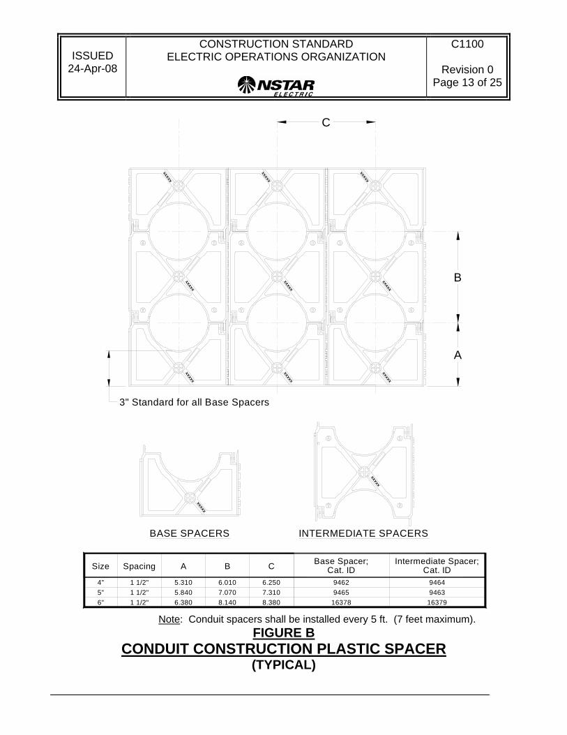
7.8 Conduit Spacers – Conduit Spacers shall be of the approved type per NSTAR Material Standard, “M1000, PVC Conduit and Fittings”. Spacers shall be installed at typically 5 ft. spacing (7 ft. maximum) along the ductbank. Refer to Figure “B” for conduit construction plastic spacers details.
7.9 Conduit Sweeps and Bends – Conduit heat bending is not allowed. All sweeps and bends shall be constructed using pre-fabricated approved fittings. Refer to “Table 3 – Conduit Sweeps and Angle Fittings”.
7.10 Mandrel – Upon completion of the duct bank installation or direct buried ducts, a standard flexible mandrel, (not less than 12 inches long with a diameter not less than ½ inch less than the inside diameter of the duct) shall be pulled through each duct to loosen particles of earth, sand and other foreign material left in the line. A brush with stiff bristles shall then be pulled through each duct to remove the loosened particles. The diameter of the brush shall be the same as, or slightly larger than the diameter of the duct.
7.11 Building Wall Construction – When conduit or ductbank enters a structure and differential settlement is expected, construction details shall be per Figure “C”.
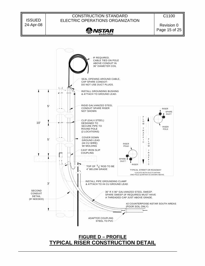
7.12 Riser Construction – When conduit transitions from underground to above ground a galvanized steel conduit with a 36 inch radius sweep shall be used. For typical riser construction details refer to Figure “D”.
7.13 All conduit shall have “mule tape” or equal, i.e. pulling tape made of woven polyester with a strength of 2500 lbs. installed within.
7.14 Transposition of Ducts – When ducts leaving one manhole/pad/equipment foundation require altering the duct bank cross section along the run, the revised configuration (and corresponding duct numbering) shall be as shown on Figure “G” unless otherwise approved by NSTAR.

ISSUED
24-Apr-08
CONSTRUCTION STANDARD ELECTRIC OPERATIONS ORGANIZATION
C1100
Revision 0 Page 6 of 25
8.0 Breaking into existing Manholes
8.1 Manhole breaks for new ductbank penetrations shall receive prior approval from NSTAR inspector. Contractors must be pre-qualified by NSTAR to work in or break into live manholes. Sidewall breaks are generally not allowed unless prior approval from NSTAR inspector.
8.2 All newly formed bell mouths shall be installed per Figure “F”. 9.0 Compatible Unit Format for Conduit & Fittings
The Compatible Unit format for Conduit & Fittings, which are considered Non-electric Facilities, is described below: 9.1 Conduit, Banks and Riser CU Formats -unit lengths are noted in CU title:
NC (Application/Material) (Size) - (Quantity {row x height})
(Application/Material) - D – Direct Buried (schedule 40 PVC) E – Concrete Encased PVC (Type EB with spacers needed) RP – Riser PVC (pipe and sweep- schedule. 40) RS – Riser steel (pipe and sweep – galv. steel) S – Steel Conduit FLEX – flexible PVC, schedule 40
(Size) – Conduit inside diameter (inches) (Quantity) – Cross section, rows x height (greater than one only, if one leave blank)
Examples: NCE4-3x3: 3x3 duct bank, 4”, PVC type EB NCRS4: 4”, galvanized steel, riser pipe and sweep NCD2: single 2” schedule 40 PVC duct, direct buried 9.2 Conduit Fitting CU Formats:
NF (Material) (Size) - (Type) – {detail below}
(Material) – P – PVC schedule 40 or DB/EB, S – Steel, I - Iron (Size) – Conduit inside diameter in inches (Type) - SW – Sweeps & angle fittings in degrees
(Angle)-(Radius) - For 36 in. radius bends leave blank, show all others. R - Reducers (A side – B side) – in inches CAP - Riser Caps, PLUG – Duct Plugs, CPL – Straight Couplings RADP - Riser Adapter, FA – Fairleader, BEL40 – Endbell – Sch 40, BELEB - Endbell – EB, SLIP – Slip Coupling, SPLIT – Split Repair PS - PVC to Steel Coupling, GNDBUSH – Grounding Bushing, GNDUCONN – pipe ground connector

ISSUED
24-Apr-08
CONSTRUCTION STANDARD ELECTRIC OPERATIONS ORGANIZATION
C1100
Revision 0 Page 7 of 25
Examples: NFP4-SW90-24: 4”, PVC, 90 degree angle sweep with 24 in radius NFP5-SW22: 5” PVC duct, 22.5 degree sweep, 36 in radius NFP6-CAP: 6” PVC riser cap (for spare)
NFP5-CPL: 5” PVC straight coupling NFS4-GNDBUSH: 4” Grounding Bushing:
9.3 Conduit Accessory CU Formats: NA (Material) - (Size option if any) Material – CM - PVC cement, MT - marker tape, FL- fish line, DX - duxseal,
DF - duct foam, CP - cold patch, FA – fairleader 10.0 Ductbank Compatible Units
10.1 Ductbanks shall be designed using Compatible Units (CUs). The table below references the CUs for the most commonly used ductbanks for distribution construction. Refer to NSTAR Material Standard, “M1000, PVC Conduit & Fittings” for additional information.
10.2 Refer to Figure “E” for typical ductbank construction details. 10.3 Figures 1 thru 21 noted below refer to standard cross sections on pages 19-24.
DUCTBANK COMPATIBLE UNIT REFERENCE TABLE
Note: Each single duct bank CU includes 20 ft of trenching, needed lengths of conduit, spacers, concrete, backfill & resurfacing.
NCE4-4x4 NCE5-4x4 NCE6-4x4
5421
FIG
NCE4-3x1
NCE4-2x1
6" Ducts5" Ducts4" Ducts
NCE5-3x1
NCE5-2x1
NCE6-3x1
NCE6-2x1
NCE4-3x2
NCE4-2x2
NCE5-3x2
NCE5-2x2
NCE6-3x2
NCE6-2x2
89 NCE4-3x3
NCE4-4x2
NCE5-3x3
NCE5-4x2
NCE6-4x2
NCE6-4x2
13 NCE4-4x3 NCE5-4x3 NCE6-4x3
21

ISSUED
24-Apr-08
CONSTRUCTION STANDARD ELECTRIC OPERATIONS ORGANIZATION
C1100
Revision 0 Page 8 of 25
11.0 Bill of Materials and Compatible Units – Conduit, Fittings & Accessories – Tables 1- 6
Table 1 - PVC & Steel Conduit Only (not banks) Material Size (ID) Wall
Thickness (Type/ Sch)
Unit Length (Ft)
Catalog ID Compatible Unit
PVC – rigid 2 40 10 1197 NCD2 “ 3 40 10 1198 NCD3 “ 4 40 10 1195 NCD4 “ 4 EB 20 1362 NCE4 “ 5 40 10 1196 NCD5 “ 5 EB 20 1363 NCE5 “ 6 40 10 15174 NCD6 “ 6 EB 20 16047 NCE6
PVC – flexible
1-1/2 40 flex 1 15968 NCFLEX1.5
“ 2 40 flex 1 9480 NCFLEX2 “ 2-1/2 40 flex 1 15969 NCFLEX2.5 “ 3 40 flex 1 9481 NCFLEX3 “ 4 40 flex 1 9482 NCFLEX4
Steel, Galv 2 40 10 9474 NCS2 “ 3 40 10 1246 NCS3
Steel, Galv 4 40 10 1248 NCS4 “ 5 40 10 1249 NCS5 “ 6 40 10 15177 NCS6
Table 2 – Straight Couplings, Split Duct and Reducers (PVC to PVC Only)
Material Type Size(s) Application Catalog ID Compatible Unit
PVC Straight Coupling
2 Joining 1208 NFP2-CPL
“ “ 3 Joining 1209 NFP3-CPL “ “ 4 Joining 1210 NFP4-CPL “ “ 5 Joining 16375 NFP5-CPL “ “ 6 Joining 16355 NFP6-CPL
PVC Split Duct 2 Repair 16873 NFP2-SPLIT “ “ 3 Repair 16874 NFP3-SPLIT “ “ 4 Repair 16875 NFP4-SPLIT “ “ 5 Repair 16876 NFP5-SPLIT “ “ 6 Repair 16831 NFP6-SPLIT

ISSUED
24-Apr-08
CONSTRUCTION STANDARD ELECTRIC OPERATIONS ORGANIZATION
C1100
Revision 0 Page 9 of 25
PVC Reducer 3 to 2-1/2 change dia. 13661 NFPR3-2.5
“ “ 3 to2 change dia 13639 NFPR-3-2 “ “ 4 to 3 change dia. 16043 NFPR-4-3 “ “ 5 to 4 change dia. 16044 NFPR-5-4 “ “ 6 to 5 change dia. 16045 NFPR-6-5
Table 3 – Conduit Sweeps and Angle Fittings Material Angle
(deg) Size (ID) Radius Catalog ID Compatible Unit
PVC 5 4 N/A 1357 NFP4-SW5
“ “ 5 N/A 1358 NFP5-SW5 “ “ 6 N/A 16354 NFP6-SW5 “ 22.5 3 13 15319 NFP3-SW22-13 “ “ 4 36 1168 NFP4-SW22 “ “ 5 36 1169 NFP5-SW22 “ “ 6 48 16359 NFP6-SW22-48
PVC 45 3 13 15320 NFP3-SW45-13 “ “ 4 36 1166 NFP4-SW45 “ “ 5 36 1170 NFP5-SW45 “ “ 6 48 16358 NFP6-SW45-48 “ 90 2 18 1158 NFP2-SW90-18 “ “ 3 24 1159 NFP3-SW90-24 “ “ 4 36 1167 NFP4-SW90 “ “ 4 24 16374 NFP4-SW90-24 “ “ 4 16 7746 NFP4-SW90-16
PVC 90 4 48 16385 NFP4-SW90-48 “ “ 5 36 1171 NFP5-SW90 “ “ 5 60 16361 NFP5-SW90-60 “ “ 6 36 16363 NFP6-SW90 “ “ 6 60 16364 NFP6-SW90-60
Galv. Steel 90 2 30 16854 NFS2-SW90-30 “ “ 3 30 1173 NFS3-SW90-30 “ “ 4 36 9898 NFS4-SW90 “ “ 5 36 9899 NFS5-SW90 “ “ 6 36 15176 NFS6-SW90

ISSUED
24-Apr-08
CONSTRUCTION STANDARD ELECTRIC OPERATIONS ORGANIZATION
C1100
Revision 0 Page 10 of 25
Table 4 – Underground Conduit Plugs and End Bells Material Description Size (ID) Ends Catalog ID Compatible Unit
PVC/rubber Duct Plug 2 n/a 1634 NFP2-PLUG “ “ 3 n/a 1635 NFP3-PLUG
PVC/rubber Duct Plug 4 n/a 1636 NFP4-PLUG “ “ 5 n/a 1637 NFP5-PLUG “ “ 6 n/a 16869 NFP6-PLUG
PVC Sched 40 End Bell
2 9423 NFP2-BEL40
“ “ 3 9424 NFP3-BEL40 “ “ 4 9425 NFP4-BEL40 “ “ 5 16428 NFP5-BEL40 “ “ 6 16367 NFP6-BEL40
PVC Type EB End Bell
2 16365 NFP2-BELEB
“ “ 3 16366 NFP3-BELEB “ “ 4 1156 NFP4-BELEB “ “ 5 1157 NFP5-BELEB “ “ 6 16429 NFP6-BELEB
Table 5 – Pole Riser Sections including Fittings (Steel to PVC, Steel to Steel) Material Description Size (ID) Ends Catalog ID Compatible Unit
PVC External Cap 2 16918 NFP2-CAP
“ “ 3 16917 NFP3-CAP “ “ 4 9460 NFP4-CAP “ “ 5 16393 NFP5-CAP “ “ 6 16394 NFP6-CAP
Galv. Steel
Riser Pipe Section (steel sweep, 10 ft Rigid steel conduit, iron slip coupling & PVC-steel coupling)
2 sweep RS cond slip cplg thrd cplg
16854 9474 16351 9513
NCRS2
“ “ 3 sweep RS cond slip cplg thrd cplg
1173 1246 1343 9514
NCRS3
“ “ 4 sweep RS cond slip cplg thrd cplg
9898 1248 1345 1099
NCRS4
ISSUED
24-Apr-08
CONSTRUCTION STANDARD ELECTRIC OPERATIONS ORGANIZATION
C1100
Revision 0 Page 11 of 25
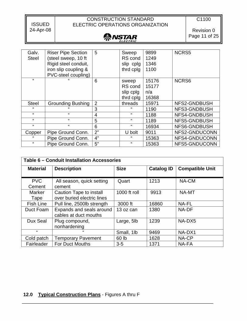
Galv. Steel
Riser Pipe Section (steel sweep, 10 ft Rigid steel conduit, iron slip coupling & PVC-steel coupling)
5 Sweep RS cond slip cplgthrd cplg
9899 1249 1346 1100
NCRS5
“ “ 6 sweep RS cond slip cplg thrd cplg
15176 15177 n/a 16368
NCRS6
Steel Grounding Bushing 2 threads 15971 NFS2-GNDBUSH “ “ 3 “ 1190 NFS3-GNDBUSH “ “ 4 “ 1188 NFS4-GNDBUSH “ “ 5 “ 1189 NFS5-GNDBUSH “ “ 6 “ 16934 NFS6-GNDBUSH
Copper Pipe Ground Conn. 2” U bolt 9011 NFS2-GNDUCONN“ Pipe Ground Conn. 4” “ 15363 NFS4-GNDUCONN“ Pipe Ground Conn. 5” “ 15363 NFS5-GNDUCONN
Table 6 – Conduit Installation Accessories
Material Description Size Catalog ID Compatible Unit
PVC Cement
All season, quick setting cement
Quart 1213 NA-CM
Marker Tape
Caution Tape to install over buried electric lines
1000 ft roll 9913 NA-MT
Fish Line Pull line, 2500lb strength 3000 ft 16860 NA-FL Duct Foam Expands and seals around
cables at duct mouths 13 oz can 1380 NA-DF
Dux Seal
Plug compound, nonhardening
Large, 5lb 1239 NA-DX5
“ “ Small, 1lb 9469 NA-DX1 Cold patch Temporary Pavement 60 lb 1628 NA-CP Fairleader For Duct Mouths 3-5 1371 NA-FA
12.0 Typical Construction Plans - Figures A thru F

ISSUED
24-Apr-08
CONSTRUCTION STANDARD ELECTRIC OPERATIONS ORGANIZATION
C1100
Revision 0 Page 12 of 25
Schedule 40 P.V.C.Secondary Conduit
Shall Enter 30"Minimum Below
Surface of Street &to Enter M.H.not
less than 30" BelowSurface of Street.
3" Schedule 40P.V.C. Conduiton All Multiple
Lighting Circuits
Joint Box (Typ)
Mult. LampPost (Typ)
LineM.H.
Transformer M.H.
MainDuctLines
5" Min.
Station
Use 6" Conduitfor StationGetaways.
Distribution Pole
Standpipe
Schedule 40 P.V.C. ConduitShall be 30" Minimum Below
Surface of Street and toEnter M.H. not Less than
30" Minimum BelowSurface of the Street
Series Lamp Post
3" Schedule 40 P.V.C. Conduiton all Lighting Circuits
Main Duct Linefrom Getaway M.H.
shall be 6" Min.(Typ.)
Getaway M.H.(Typ.)
FIGURE A - PLAN VIEW TYPICAL DISTRIBUTION CONDUIT CONSTRUCTION DETAILS
ISSUED
24-Apr-08
CONSTRUCTION STANDARD ELECTRIC OPERATIONS ORGANIZATION
C1100
Revision 0 Page 13 of 25
xxxx
x
xxxx
x
xxxx
x
xxxxxxxxxx
xxxxxxxxxx
xxxxxxxxxx
3" Standard for all Base Spacers
xxxxx
xxxxx
BASE SPACERS INTERMEDIATE SPACERS
Size Spacing A B C
4" 1 1/2" 5.310 6.010 6.2505" 1 1/2" 5.840 7.070 7.3106" 1 1/2" 6.380 8.140 8.380
C
A
B
Base Spacer;Cat. ID
Intermediate Spacer;Cat. ID
94629465
16378
94649463
16379 Note: Conduit spacers shall be installed every 5 ft. (7 feet maximum).
FIGURE B CONDUIT CONSTRUCTION PLASTIC SPACER
(TYPICAL)

ISSUED
24-Apr-08
CONSTRUCTION STANDARD ELECTRIC OPERATIONS ORGANIZATION
C1100
Revision 0 Page 14 of 25
8"
MIN. 20'
To Manhole
Type E.B. P.V.C. Pipe
Steel to P.V.C.Couplings
20' Lengths of Steel Pipeto Provide Shear Strength
Concrete Flush withBuilding Wall
BuildingWall
Sikaflex-1a orEquivalent Seal
(Typ. All Around)
Grout In Around Pipes
settlement of building or conduit is anticipated.Building wall construction to be used wherever
Note:
FIGURE C – PLAN VIEW BUILDING WALL CONSTRUCTION
ISSUED
24-Apr-08
CONSTRUCTION STANDARD ELECTRIC OPERATIONS ORGANIZATION
C1100
Revision 0 Page 15 of 25
TOP OF 5 8" ROD TO BE4" BELOW GRADE
INSTALL PIPE GROUNDING CLAMP& ATTACH TO #4 CU GROUND LEAD
SECONDCONDUITDETAIL
(IF NEEDED)
FLOW
TRAFFIC
FLOW
TRAFFIC
TYPICAL STREET OR ROADWAY
RISERPOLE
SPAREDUCT
RISER
RISERPOLE
SPAREDUCT
RISER
IF REQUIRED,CABLE TIED ON POLEABOVE CONDUIT IN36" DIAMETER COIL
36" R X 90° GALVANIZED STEEL SWEEP.SPARE SWEEP (IF REQUIRED) MUST HAVEA THREADED CAP JUST ABOVE GRADE.
#2 COUNTERPOISE-NSTAR SOUTH AREAS(POOR SOIL ONLY)
ADAPTER COUPLINGSTEEL TO PVC
SEAL OPENING AROUND CABLE,CAP SPARE CONDUIT-DO NOT USE DUCT PLUGS.
INSTALL GROUNDING BUSHING& ATTACH TO GROUND LEAD.
RIGID GALVANIZED STEELCONDUIT SPARE RISERNOT SHOWN
CLIP (GALV.STEEL)DESIGNED TOSECURE PIPE TOROUND POLE(2 LOCATIONS)
COVER DOWNGROUND LEAD(#4 CU WIRE)W/ MOLDING
CAST IRON SLIPCOUPLING
*LOCATE BOTH DUCTS WITHINONE POLE QUARTER AS SHOWN ABOVE.
5'
5'
10'
3'
FIGURE D – PROFILE TYPICAL RISER CONSTRUCTION DETAIL
ISSUED
24-Apr-08
CONSTRUCTION STANDARD ELECTRIC OPERATIONS ORGANIZATION
C1100
Revision 0 Page 16 of 25
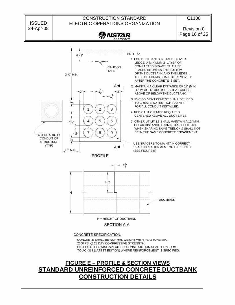
6 - 9"
CAUTIONTAPE
NOTES:
4. RED CAUTION TAPE REQUIRED.CENTERED ABOVE ALL DUCT LINES.
7 8 9
654
321
11 2"3"
112"3"
3"11 2"
3"
112"
3'-0" MIN.
USE SPACERS TO MAINTAIN CORRECTSPACING & ALIGNMENT OF THE DUCTS(SEE FIGURE B)
1. FOR DUCTBANKS INSTALLED OVERLEDGE; A MINIMUM 2" LAYER OFCOMPACTED GRAVEL SHALL BEPLACED BETWEEN THE BOTTOMOF THE DUCTBANK AND THE LEDGE.THE SIDE FORMS SHALL BE REMOVEDAFTER THE CONCRETE IS SET.
2. MAINTAIN A CLEAR DISTANCE OF 12" (MIN)FROM ALL STRUCTURES THAT CROSSABOVE OR BELOW THE DUCTBANK.
3. PVC SOLVENT CEMENT SHALL BE USEDTO CREATE WATER-TIGHT JOINTSFOR ALL CONDUIT INSTALLED.
CONCRETE SPECIFICATION:CONCRETE SHALL BE NORMAL WEIGHT WITH PEASTONE MIX,2500 PSI @ 28 DAY COMPRESSIVE STRENGTH.UNLESS OTHERWISE SPECIFIED, CONSTRUCTION SHALL CONFORMTO ACI-318 (LATEST EDITION) WHERE REINFORCEMENT IS SPECIFIED.
12" MIN.
OTHER UTILITYCONDUIT ORSTRUCTURE
(TYP)
5. OTHER UTILITIES SHALL MAINTAIN A 12" MIN.CLEAR DISTANCE FROM NSTAR ELECTRICWHEN SHARING SAME TRENCH & SHALL NOTBE IN THE SAME CONCRETE ENCASEMENT.
H/2
PROFILE
A
A
SECTION A-A
DUCTBANK
H = HEIGHT OF DUCTBANK
H
134"
FIGURE E – PROFILE & SECTION VIEWS STANDARD UNREINFORCED CONCRETE DUCTBANK
CONSTRUCTION DETAILS

ISSUED
24-Apr-08
CONSTRUCTION STANDARD ELECTRIC OPERATIONS ORGANIZATION
C1100
Revision 0 Page 17 of 25
6" Min.212"
512" 51
2"
8"
1" 1"
X X
M.H
. WA
LL
X X
XX
SECTION "A-A"
DUCT FACE
21 2"
1"
DETAIL OF DUCT MOUTH
Y 14"
14"
Y+12" Y+1
2"
DUCT SIZE
212"
DUCT MOUTH FOR SERVICE PIPES, ETC.
14"
14"
Pipe O.D.plus 1 inch
Duct Size
6 12" 5"4"
7 12" 6"5"
8 12" 7"6"
X Y
Notes:1. Ducts shall be 5" size unless otherwise specified.2. Ducts shall be terminated with a matching schedule
PVC end bell, which shall then be sealed aroundwith mortar mix.
3" (Typ.) X
FIGURE F
MANHOLE BELLMOUTH CONSTRUCTION

ISSUED
24-Apr-08
CONSTRUCTION STANDARD ELECTRIC OPERATIONS ORGANIZATION
C1100
Revision 0 Page 18 of 25
Foundation, shall be
This Standard Specifies the Typical Arrangement of Transposed Duct Numbering
2
6
3
4 DUCT
6 DUCT
8 DUCT
12 DUCT
Connect Left to Rightas Follows:
1 to 22 to 43 to 34 to 1
Connect Left to Rightas Follows:
1 to 22 to 43 to 14 to 65 to 36 to 5
Connect Left to Rightas Follows:
1 to 22 to 43 to 34 to 15 to 86 to 67 to 58 to 7
Connect Left to Rightas Follows:
1 to 42 to 13 to 34 to 25 to 86 to 57 to 78 to 6
9 to 1110 to 1011 to 1212 to 9
Configuration LeavingManhole/Pad/
Equipment Fdn.(Typ)
ConfigurationEntering orApproaching
Manhole/Pad/Equipment Fdn.
(Typ)
as the Configuration changes from Horizontal to Vertical or vice versa.
Notes:1. The open duct ends, as
viewed from the center ofthe Manhole/Pad/Equipment
numbered as shown onFigures No. 1 - 23.
2. If other duct transpositionsare required priorapproval from NSTARis required.
8
12
34
12
34
12
3
12
34
45
65
6
12
34
12
34
56
78
56
7
4
18
7
5
9
21
43
65
87
9
FIGURE G TRANSPOSITION OF DUCTS – (WHEN NECESSARY)

ISSUED
24-Apr-08
CONSTRUCTION STANDARD ELECTRIC OPERATIONS ORGANIZATION
C1100
Revision 0 Page 19 of 25
13.0 Duct Bank Cross Sections – Figures 1 thru 23 Standard and Nonstandard (Alternate) Designs shown to support old construction.
DUCT BANK LAYOUT FOR 4”, 5”, & 6” CONDUIT
(NON-REINFORCED CONCRETE)
Numbers in Duct Indicate Numbering System whenViewed from the Open End of a Ductbank.
(Alternate)
3"
FIG. 5 6-DUCTS
FIG. 4 4-DUCTSFIG. 3 4-DUCTS
FIG. 2 3-DUCTSFIG. 1 2-DUCTS
21"29"
21"21"
12 12"37"
12 12"29"
12 12"21"
BInchesInches
A6" Ducts5" Ducts
AInches Inches
B
18 12" 11 12"
25 12" 11 12"
32 12" 11 12"
18 12" 18 12"
25 12" 18 12"5 16 12"22 12"
4 16 12"16 12"
3 10 12"28 12"
10 12"22 12"2
10 12"16 12"1
FIG BInchesInches
A4" Ducts
DIMENSIONS
32121
4321
43
21
4 5 6
321
112"
B
3"
11 2"3"
3"
3" 112"
A
3"
11 2"
112"
112"
112"
3"
3" 3"
3"3"
3"112"
A
B
A
B
B
AB
A
112"11
2"3" 3"
3"3"
3"3"
3"3"
112"
NOTE: See pages 25 for duct bank weights and concrete quantities.

ISSUED
24-Apr-08
CONSTRUCTION STANDARD ELECTRIC OPERATIONS ORGANIZATION
C1100
Revision 0 Page 20 of 25
DUCT BANK LAYOUT FOR 4”, 5”, & 6” CONDUIT (NON-REINFORCED CONCRETE)
FIG. 6 6-DUCTS FIG. 7 8-DUCTS
FIG. 8 8-DUCTS FIG. 9 9-DUCTS
3"
B
112"
11 2"11 2"
112"
B
3"
11 2"3"
3" 112"
A
3"11 2"
1 2 3
4 5 6
987
1 2 3 4
5 6 7 8
1 2
3 4
5 6
7 8
1 2
3 4
5 6
DIMENSIONS4" Ducts
AInches Inches
BFIG
16 12" 22 12"6
16 12" 28 12"7
28 12" 16 12"8
22 12" 22 12"9 25 12"25 12"
18 12"32 12"
32 12"18 12"
25 12"18 12"
BInchesInches
A5" Ducts 6" Ducts
AInches Inches
B
21" 29"
21" 37"
37" 21"
29" 29"
3"
11 2"3"
3"112"
B
A
3" 3"
A
B
11 2"
112"
11 2"3"
3"
3"112"
A
3"
3"112"
3"
(Alternate) (Alternate)
Numbers in Duct Indicate Numbering System whenViewed from the Open End of a Ductbank.
NOTE: See pages 25 for duct bank weights and concrete quantities.
ISSUED
24-Apr-08
CONSTRUCTION STANDARD ELECTRIC OPERATIONS ORGANIZATION
C1100
Revision 0 Page 21 of 25
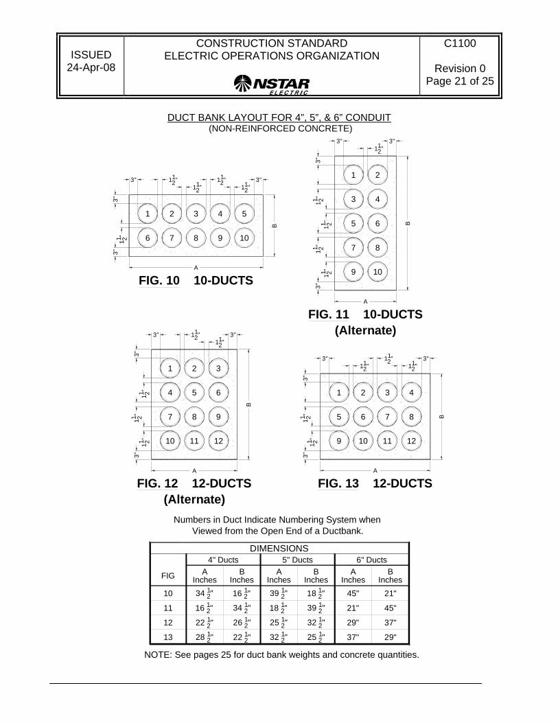
DUCT BANK LAYOUT FOR 4”, 5”, & 6” CONDUIT (NON-REINFORCED CONCRETE)
Numbers in Duct Indicate Numbering System whenViewed from the Open End of a Ductbank.
(Alternate)
(Alternate)
3"
A
B
11 2"3"
3" 112" 3"
11 2"11 2"
1 3
4 6
7 9
10 12
11 2"11 2" 7 8
3"
A
B11 2"3"
3"112"
3"
11 2"
1 2
3 4
5 6
9 10
112"
112"
9
4
112"
11 2"3"
3"
3" 112"
A
3"
B
1 2 3 5
6 7 8 10
DIMENSIONS4" Ducts
AInches Inches
BFIG
10 34 12" 16 12"
11 16 12" 34 12"
22 12" 26 12"12
28 12" 22 12"13 25 12"32 12"
32 12"25 12"
39 12"18 12"
18 12"39 12"
BInchesInches
A5" Ducts 6" Ducts
AInches Inches
B
45" 21"
21" 45"
29" 37"
37" 29"
112"
11
7
3
112"
B
3"
11 2"3"
3"112"
A
3"11 2"
1 2 4
5 6 8
12109
FIG. 13 12-DUCTSFIG. 12 12-DUCTS
FIG. 11 10-DUCTS
FIG. 10 10-DUCTS
112"
11
8
5
2
NOTE: See pages 25 for duct bank weights and concrete quantities.

ISSUED
24-Apr-08
CONSTRUCTION STANDARD ELECTRIC OPERATIONS ORGANIZATION
C1100
Revision 0 Page 22 of 25
DUCT BANK LAYOUT FOR 4”, 5”, & 6” CONDUIT (NON-REINFORCED CONCRETE)
Numbers in Duct Indicate Numbering System whenViewed from the Open End of a Ductbank.
(Alternate) (Alternate)
11 2" 9 10
1413
65
43
21
11 2"
3"112"
3"
3"11 2"
B
A
3"
8711 2"
FIG. 16 14-DUCTS
11 1211 2"11 2"
61"21"
53 12"21"
21"53 12"
BInchesInches
A6" Ducts5" Ducts
AInches Inches
B
46 12" 18 12"
18 12" 46 12"
18 12" 53 12"16 46 12"16 12"
15 40 12"16 12"
14 16 12"40 12"
FIG BInchesInches
A4" Ducts
DIMENSIONS
FIG. 14 12-DUCTS
112"
10
4
112"
11 2"3"
3"
3"112"
A
3"
B
1 2 3 6
7 8 9 1211
5
112"
112"
FIG. 15 12-DUCTS
11 2" 7 8
3"
A
B
11 2"3"
3"112"
3"
11 2"
1 2
3 4
5 6
11 12
10911 2"
11 2"
NOTE: See pages 25 for duct bank weights and concrete quantities.

ISSUED
24-Apr-08
CONSTRUCTION STANDARD ELECTRIC OPERATIONS ORGANIZATION
C1100
Revision 0 Page 23 of 25
DUCT BANK LAYOUT FOR 4”, 5”, & 6” CONDUIT (NON-REINFORCED CONCRETE)
D
(Alternate)
(Alternate)Numbers in Duct Indicate Numbering System when
Viewed from the Open End of a Ductbank.
3"
21
1412
119
86
53
11 2"11 2"
3"112"3"
11 2"
B
A
3"
4
7
10
13
112"
FIG. 17 14-DUCTS
9"
C
C11 2"
D
112"
112"
112"
112"
112"
N/A
N/AN/A
N/AN/A
N/A N/A
N/A
14"
16"
DInchesInches
C
11"
11"10"
10"
CInches Inches
D
14"
12"
N/A
N/A
10"
12"
DInchesInches
C
9"
N/A
N/A 29"45"
45"29"
25 12"37"
33 12"29"
BInchesInches
A6" Ducts5" Ducts
AInches Inches
B
25 12" 29 12"
32 12" 22 12"
25 12" 39 12"
39 12" 25 12"20 22 12"34 12"
19 34 12"22 12"
19 12"28 12"18
25 12"22 12"17
FIG BInchesInches
A4" Ducts
DIMENSIONS
4
9
14
FIG. 20 15-DUCTS
11 12 15
1076
521
11 2"
3"
A
112"3"
3"11 2"
3"
B
112"
3
8
1311 2"11 2" 1110 12
1513
97
64
31
11 2"
3"112"3"
3"11 2" B
A
3"
2
5
8
14
112"
FIG. 19 15-DUCTS
2
5
9
13
FIG. 18 14-DUCTS
12
8
4
1
3"
A
B11 2"
3" 3"11 2"
11 2"
3 6
7 10
11 14
NOTE: See pages 25 for duct bank weights and concrete quantities.

ISSUED
24-Apr-08
CONSTRUCTION STANDARD ELECTRIC OPERATIONS ORGANIZATION
C1100
Revision 0 Page 24 of 25
DUCT BANK LAYOUT FOR 4”, 5”, & 6” CONDUIT (NON-REINFORCED CONCRETE)
(Alternate)
Numbers in Duct Indicate Numbering System whenViewed from the Open End of a Ductbank.
DInchesInches
C CInches Inches
D
N/A
N/AN/A
N/A N/A
N/A N/A
N/A
9 10 121111 2"11 2"
11 2" 1211
FIG. 22 16-DUCTS
11 2" 7 8
3"
A
B
11 2"3"
3"112"
3"
11 2"
1 2
3 4
5 6
15 16
10911 2"141311 2"
11 2"
DIMENSIONS4" Ducts
AInches Inches
BFIG
28 12" 28 12"21
16 12" 52 12"22 60 12"18 12"
32 12"32 12"
BInchesInches
A5" Ducts 6" Ducts
AInches Inches
B
37" 37"
21" 69"N/A
N/A
CInches Inches
D
N/A
N/A
112"
15
7
3
B
3"11 2"
3"
3"112"
A
3"
1 2 4
5 6 8
161413
FIG. 21 16-DUCTS
11 2"
11 2" 13 14
1716
87
54
21
11 2"
112"
3"
3"11 2"
B
A
3"
111011 2"
FIG. 23 18-DUCTS
12
112"
3"
3
6
9
18
15
23 N/AN/AN/A N/AN/AN/A 29"25 12" 46 12"22 12" 40 12" 53 12"
NOTE: See pages 25 for duct bank weights and concrete quantities.

ISSUED
24-Apr-08
CONSTRUCTION STANDARD ELECTRIC OPERATIONS ORGANIZATION
C1100
Revision 0 Page 25 of 25
14.0 Conduit Bank Concrete Requirements and Weights per linear foot.
CONDUIT CONSTRUCTION DUCT SIZES, WEIGHTS & CONCRETE QUANTITIES
No. of Ducts 4 Inch Dia. 5 Inch Dia. 6 Inch Dia.
Unreinforced Concrete PVC Duct & Cable
Unreinforced Concrete PVC Duct & Cable
Unreinforced Concrete PVC Duct & Cable
lbs/lin. ft. cu.yds/lin. ft lbs/lin. ft. cu.yds/lin. ft lbs/line. ft. ft. cu.yds/lin. ft.2 180 0.0363 200 200 228 0.05 3 245 0.0483 274 274 312 0.067
4(2wx2D) 285 0.0536 316 316 373 0.078 4 (4W) 315 0.0606 347 347 394 0.083
6 385 0.0709 432 432 508 0.1037 8 490 0.0882 548 548 641 0.129 9 530 0.0931 590 590 687 0.1367
10 600 0.106 663 663 774 0.154 12 (4Wx3D) 675 0.116 748 748 867 0.17 12 (6Wx2D) 700 0.123 778 778 918 0.183
14 810 0.141 858 858 984 0.191 15 815 0.138 904 904 1048 0.203
16 (4Wx4D) 840 0.141 948 948 1095 0.211 16 (2Wx8D) 865 0.155 961 961 1186 0.231 18 (3Wx6D) 946 0.161 1063 1063 1261 0.24
15.0 Reference Standards
13.1 W1000, “Entering and Working in Underground Locations including Subsurface Vaults” 13.2 C1101, “Distribution Duct bank Construction, and (Steel Reinforced Concrete)”
16.0 Signature Approval
Approved by: Amin Jessa Director, Distribution Engineering
Related Documents