COMX-CORE Series Installation and Use P/N: 6806800K11F August 2014

Welcome message from author
This document is posted to help you gain knowledge. Please leave a comment to let me know what you think about it! Share it to your friends and learn new things together.
Transcript

COMX-CORE SeriesInstallation and UseP/N: 6806800K11FAugust 2014

© Copyright 2014 Artesyn Embedded Technologies, Inc.
All rights reserved.
TrademarksArtesyn Embedded Technologies, Artesyn and the Artesyn Embedded Technologies logo are trademarks and service marks of Artesyn Embedded Technologies, Inc.© 2014 Artesyn Embedded Technologies, Inc. All other product or service names are the property of their respective owners.
Intel® is a trademark or registered trademark of Intel Corporation or its subsidiaries in the United States and other countries.
Java™ and all other Java-based marks are trademarks or registered trademarks of Oracle America, Inc. in the U.S. and other countries.
Microsoft®, Windows® and Windows Me® are registered trademarks of Microsoft Corporation; and Windows XP™ is a trademark of Microsoft Corporation.
PICMG®, CompactPCI®, AdvancedTCA™ and the PICMG, CompactPCI and AdvancedTCA logos are registered trademarks of the PCI Industrial Computer Manufacturers Group.
UNIX® is a registered trademark of The Open Group in the United States and other countries.
NoticeWhile reasonable efforts have been made to assure the accuracy of this document, Artesyn assumes no liability resulting from any omissions in this document, or from the use of the information obtained therein. Artesyn reserves the right to revise this document and to make changes from time to time in the content hereof without obligation of Artesyn to notify any person of such revision or changes.
Electronic versions of this material may be read online, downloaded for personal use, or referenced in another document as a URL to an Artesyn website. The text itself may not be published commercially in print or electronic form, edited, translated, or otherwise altered without the permission of Artesyn.
It is possible that this publication may contain reference to or information about Artesyn products (machines and programs), programming, or services that are not available in your country. Such references or information must not be construed to mean that Artesyn intends to announce such Artesyn products, programming, or services in your country.
Limited and Restricted Rights LegendIf the documentation contained herein is supplied, directly or indirectly, to the U.S. Government, the following notice shall apply unless otherwise agreed to in writing by Artesyn.
Use, duplication, or disclosure by the Government is subject to restrictions as set forth in subparagraph (b)(3) of the Rights in Technical Data clause at DFARS 252.227-7013 (Nov. 1995) and of the Rights in Noncommercial Computer Software and Documentation clause at DFARS 252.227-7014 (Jun. 1995).
Contact Address
Artesyn Embedded Technologies Artesyn Embedded Technologies
Marketing Communications Lilienthalstr. 17-19
2900 S. Diablo Way, Suite 190 85579 Neubiberg/Munich
Tempe, Arizona 85282 Germany

Contents
COMX-CORE Series Installation and Use (6806800K11F) 3
About this Manual . . . . . . . . . . . . . . . . . . . . . . . . . . . . . . . . . . . . . . . . . . . . . . . . . . . . . . . . . . . . . . . . . . . . . . . 13
1 Introduction . . . . . . . . . . . . . . . . . . . . . . . . . . . . . . . . . . . . . . . . . . . . . . . . . . . . . . . . . . . . . . . . . . . . . . . . . 17
1.1 Features . . . . . . . . . . . . . . . . . . . . . . . . . . . . . . . . . . . . . . . . . . . . . . . . . . . . . . . . . . . . . . . . . . . . . . . . . . . 171.2 Standard Compliances . . . . . . . . . . . . . . . . . . . . . . . . . . . . . . . . . . . . . . . . . . . . . . . . . . . . . . . . . . . . . . 201.3 Mechanical Data . . . . . . . . . . . . . . . . . . . . . . . . . . . . . . . . . . . . . . . . . . . . . . . . . . . . . . . . . . . . . . . . . . . 22
1.3.1 COMX-CORE Series Mechanical Data . . . . . . . . . . . . . . . . . . . . . . . . . . . . . . . . . . . . . . . . . . . 221.3.2 Heat Spreader Mechanical Data . . . . . . . . . . . . . . . . . . . . . . . . . . . . . . . . . . . . . . . . . . . . . . . . 241.3.3 Cooler Mechanical Data. . . . . . . . . . . . . . . . . . . . . . . . . . . . . . . . . . . . . . . . . . . . . . . . . . . . . . . 25
1.4 Ordering Information . . . . . . . . . . . . . . . . . . . . . . . . . . . . . . . . . . . . . . . . . . . . . . . . . . . . . . . . . . . . . . . 261.4.1 Supported Board Models . . . . . . . . . . . . . . . . . . . . . . . . . . . . . . . . . . . . . . . . . . . . . . . . . . . . . . 271.4.2 Board Accessories . . . . . . . . . . . . . . . . . . . . . . . . . . . . . . . . . . . . . . . . . . . . . . . . . . . . . . . . . . . . 27
1.5 Board Identification . . . . . . . . . . . . . . . . . . . . . . . . . . . . . . . . . . . . . . . . . . . . . . . . . . . . . . . . . . . . . . . . . 28
2 Hardware Preparation and Installation . . . . . . . . . . . . . . . . . . . . . . . . . . . . . . . . . . . . . . . . . . . . . . . . . 29
2.1 Environmental and Power Requirements . . . . . . . . . . . . . . . . . . . . . . . . . . . . . . . . . . . . . . . . . . . . . . 292.1.1 Environmental Requirements. . . . . . . . . . . . . . . . . . . . . . . . . . . . . . . . . . . . . . . . . . . . . . . . . . 292.1.2 Thermal Requirements . . . . . . . . . . . . . . . . . . . . . . . . . . . . . . . . . . . . . . . . . . . . . . . . . . . . . . . 302.1.3 Power Requirements . . . . . . . . . . . . . . . . . . . . . . . . . . . . . . . . . . . . . . . . . . . . . . . . . . . . . . . . . 34
2.2 Board Thermal Management and Placement . . . . . . . . . . . . . . . . . . . . . . . . . . . . . . . . . . . . . . . . . . . 362.2.1 Board Thermal Management . . . . . . . . . . . . . . . . . . . . . . . . . . . . . . . . . . . . . . . . . . . . . . . . . . 36
2.3 Unpacking and Inspecting the Module . . . . . . . . . . . . . . . . . . . . . . . . . . . . . . . . . . . . . . . . . . . . . . . . 372.4 Preparing the Installation Environment . . . . . . . . . . . . . . . . . . . . . . . . . . . . . . . . . . . . . . . . . . . . . . . . 382.5 Memory Module Installation and Removal . . . . . . . . . . . . . . . . . . . . . . . . . . . . . . . . . . . . . . . . . . . . . 402.6 eUSB Flash Disk Installation and Removal . . . . . . . . . . . . . . . . . . . . . . . . . . . . . . . . . . . . . . . . . . . . . . 422.7 Heat Spreader/Cooler Installation and Removal . . . . . . . . . . . . . . . . . . . . . . . . . . . . . . . . . . . . . . . . 442.8 Module Installation and Removal with Carrier Board . . . . . . . . . . . . . . . . . . . . . . . . . . . . . . . . . . . . 46
3 Controls, LEDs, and Connectors . . . . . . . . . . . . . . . . . . . . . . . . . . . . . . . . . . . . . . . . . . . . . . . . . . . . . . . . 49
3.1 Board Layout . . . . . . . . . . . . . . . . . . . . . . . . . . . . . . . . . . . . . . . . . . . . . . . . . . . . . . . . . . . . . . . . . . . . . . . 493.2 Connectors and Switches . . . . . . . . . . . . . . . . . . . . . . . . . . . . . . . . . . . . . . . . . . . . . . . . . . . . . . . . . . . . 51
3.2.1 COM Express Connector . . . . . . . . . . . . . . . . . . . . . . . . . . . . . . . . . . . . . . . . . . . . . . . . . . . . . . 513.2.2 USB Flash Connector . . . . . . . . . . . . . . . . . . . . . . . . . . . . . . . . . . . . . . . . . . . . . . . . . . . . . . . . . 563.2.3 DIP Switch Setting. . . . . . . . . . . . . . . . . . . . . . . . . . . . . . . . . . . . . . . . . . . . . . . . . . . . . . . . . . . . 57
Contents

COMX-CORE Series Installation and Use (6806800K11F)
Contents
4
ContentsContents
3.3 On-board LEDs . . . . . . . . . . . . . . . . . . . . . . . . . . . . . . . . . . . . . . . . . . . . . . . . . . . . . . . . . . . . . . . . . . . . . 57
4 Functional Description . . . . . . . . . . . . . . . . . . . . . . . . . . . . . . . . . . . . . . . . . . . . . . . . . . . . . . . . . . . . . . . . 59
4.1 Block Diagram . . . . . . . . . . . . . . . . . . . . . . . . . . . . . . . . . . . . . . . . . . . . . . . . . . . . . . . . . . . . . . . . . . . . . 594.2 Processor . . . . . . . . . . . . . . . . . . . . . . . . . . . . . . . . . . . . . . . . . . . . . . . . . . . . . . . . . . . . . . . . . . . . . . . . . . 604.3 Chipset . . . . . . . . . . . . . . . . . . . . . . . . . . . . . . . . . . . . . . . . . . . . . . . . . . . . . . . . . . . . . . . . . . . . . . . . . . . . 614.4 Clock Generator . . . . . . . . . . . . . . . . . . . . . . . . . . . . . . . . . . . . . . . . . . . . . . . . . . . . . . . . . . . . . . . . . . . . 614.5 System Memory . . . . . . . . . . . . . . . . . . . . . . . . . . . . . . . . . . . . . . . . . . . . . . . . . . . . . . . . . . . . . . . . . . . . 624.6 SMBus Interface and Devices . . . . . . . . . . . . . . . . . . . . . . . . . . . . . . . . . . . . . . . . . . . . . . . . . . . . . . . . . 624.7 Video . . . . . . . . . . . . . . . . . . . . . . . . . . . . . . . . . . . . . . . . . . . . . . . . . . . . . . . . . . . . . . . . . . . . . . . . . . . . . 64
4.7.1 VGA and LVDS . . . . . . . . . . . . . . . . . . . . . . . . . . . . . . . . . . . . . . . . . . . . . . . . . . . . . . . . . . . . . . . 644.7.2 Digital Display Interfaces . . . . . . . . . . . . . . . . . . . . . . . . . . . . . . . . . . . . . . . . . . . . . . . . . . . . . . 654.7.3 PEG and eDP Compatibility . . . . . . . . . . . . . . . . . . . . . . . . . . . . . . . . . . . . . . . . . . . . . . . . . . . . 67
4.8 PCI Express Port . . . . . . . . . . . . . . . . . . . . . . . . . . . . . . . . . . . . . . . . . . . . . . . . . . . . . . . . . . . . . . . . . . . . 694.9 SATA Interface . . . . . . . . . . . . . . . . . . . . . . . . . . . . . . . . . . . . . . . . . . . . . . . . . . . . . . . . . . . . . . . . . . . . . 704.10 USB Interface . . . . . . . . . . . . . . . . . . . . . . . . . . . . . . . . . . . . . . . . . . . . . . . . . . . . . . . . . . . . . . . . . . . . . . 724.11 USB Flash Solid State Drive . . . . . . . . . . . . . . . . . . . . . . . . . . . . . . . . . . . . . . . . . . . . . . . . . . . . . . . . . . . 734.12 Ethernet Interfaces . . . . . . . . . . . . . . . . . . . . . . . . . . . . . . . . . . . . . . . . . . . . . . . . . . . . . . . . . . . . . . . . . 744.13 LPC Interface . . . . . . . . . . . . . . . . . . . . . . . . . . . . . . . . . . . . . . . . . . . . . . . . . . . . . . . . . . . . . . . . . . . . . . . 754.14 TPM . . . . . . . . . . . . . . . . . . . . . . . . . . . . . . . . . . . . . . . . . . . . . . . . . . . . . . . . . . . . . . . . . . . . . . . . . . . . . . 754.15 SPI Interface . . . . . . . . . . . . . . . . . . . . . . . . . . . . . . . . . . . . . . . . . . . . . . . . . . . . . . . . . . . . . . . . . . . . . . . 764.16 Watchdog Timer . . . . . . . . . . . . . . . . . . . . . . . . . . . . . . . . . . . . . . . . . . . . . . . . . . . . . . . . . . . . . . . . . . . 774.17 Hardware Monitor . . . . . . . . . . . . . . . . . . . . . . . . . . . . . . . . . . . . . . . . . . . . . . . . . . . . . . . . . . . . . . . . . . 77
4.17.1 Voltage Monitor . . . . . . . . . . . . . . . . . . . . . . . . . . . . . . . . . . . . . . . . . . . . . . . . . . . . . . . . . . . . . 774.17.2 Temperature . . . . . . . . . . . . . . . . . . . . . . . . . . . . . . . . . . . . . . . . . . . . . . . . . . . . . . . . . . . . . . . . 774.17.3 Fan Monitor and Control . . . . . . . . . . . . . . . . . . . . . . . . . . . . . . . . . . . . . . . . . . . . . . . . . . . . . . 77
4.18 Audio . . . . . . . . . . . . . . . . . . . . . . . . . . . . . . . . . . . . . . . . . . . . . . . . . . . . . . . . . . . . . . . . . . . . . . . . . . . . . 774.19 Power Management . . . . . . . . . . . . . . . . . . . . . . . . . . . . . . . . . . . . . . . . . . . . . . . . . . . . . . . . . . . . . . . . 774.20 Real-time Clock (RTC) . . . . . . . . . . . . . . . . . . . . . . . . . . . . . . . . . . . . . . . . . . . . . . . . . . . . . . . . . . . . . . . 78
5 BIOS . . . . . . . . . . . . . . . . . . . . . . . . . . . . . . . . . . . . . . . . . . . . . . . . . . . . . . . . . . . . . . . . . . . . . . . . . . . . . . . . 79
5.1 POST . . . . . . . . . . . . . . . . . . . . . . . . . . . . . . . . . . . . . . . . . . . . . . . . . . . . . . . . . . . . . . . . . . . . . . . . . . . . . . 795.2 Boot Process . . . . . . . . . . . . . . . . . . . . . . . . . . . . . . . . . . . . . . . . . . . . . . . . . . . . . . . . . . . . . . . . . . . . . . . 795.3 Initiating Setup . . . . . . . . . . . . . . . . . . . . . . . . . . . . . . . . . . . . . . . . . . . . . . . . . . . . . . . . . . . . . . . . . . . . . 79

Contents
COMX-CORE Series Installation and Use (6806800K11F) 5
5.4 Setup Utility . . . . . . . . . . . . . . . . . . . . . . . . . . . . . . . . . . . . . . . . . . . . . . . . . . . . . . . . . . . . . . . . . . . . . . . 805.4.1 Main Menu . . . . . . . . . . . . . . . . . . . . . . . . . . . . . . . . . . . . . . . . . . . . . . . . . . . . . . . . . . . . . . . . . . 825.4.2 Advanced Menu . . . . . . . . . . . . . . . . . . . . . . . . . . . . . . . . . . . . . . . . . . . . . . . . . . . . . . . . . . . . . 845.4.3 Chipset Menu. . . . . . . . . . . . . . . . . . . . . . . . . . . . . . . . . . . . . . . . . . . . . . . . . . . . . . . . . . . . . . . . 945.4.4 Boot Menu . . . . . . . . . . . . . . . . . . . . . . . . . . . . . . . . . . . . . . . . . . . . . . . . . . . . . . . . . . . . . . . . . 100
5.4.4.1 Quiet Boot Option . . . . . . . . . . . . . . . . . . . . . . . . . . . . . . . . . . . . . . . . . . . . . . . . . 1015.4.5 Security Menu . . . . . . . . . . . . . . . . . . . . . . . . . . . . . . . . . . . . . . . . . . . . . . . . . . . . . . . . . . . . . . 1025.4.6 Save and Exit Menu . . . . . . . . . . . . . . . . . . . . . . . . . . . . . . . . . . . . . . . . . . . . . . . . . . . . . . . . . . 103
5.5 ACPI Wake Up Support Matrix . . . . . . . . . . . . . . . . . . . . . . . . . . . . . . . . . . . . . . . . . . . . . . . . . . . . . . . 1045.6 Default Boot Sequence . . . . . . . . . . . . . . . . . . . . . . . . . . . . . . . . . . . . . . . . . . . . . . . . . . . . . . . . . . . . . 1045.7 POST Codes . . . . . . . . . . . . . . . . . . . . . . . . . . . . . . . . . . . . . . . . . . . . . . . . . . . . . . . . . . . . . . . . . . . . . . . 105
5.7.1 Status Code Ranges . . . . . . . . . . . . . . . . . . . . . . . . . . . . . . . . . . . . . . . . . . . . . . . . . . . . . . . . . 1055.7.2 Standard Status Codes. . . . . . . . . . . . . . . . . . . . . . . . . . . . . . . . . . . . . . . . . . . . . . . . . . . . . . . 105
5.7.2.1 SEC Status Codes . . . . . . . . . . . . . . . . . . . . . . . . . . . . . . . . . . . . . . . . . . . . . . . . . . 1055.7.2.2 PEI Status Codes . . . . . . . . . . . . . . . . . . . . . . . . . . . . . . . . . . . . . . . . . . . . . . . . . . . 1065.7.2.3 PEI Beep Codes . . . . . . . . . . . . . . . . . . . . . . . . . . . . . . . . . . . . . . . . . . . . . . . . . . . . 1105.7.2.4 DXE Status Codes . . . . . . . . . . . . . . . . . . . . . . . . . . . . . . . . . . . . . . . . . . . . . . . . . . 1105.7.2.5 DXE Beep Codes . . . . . . . . . . . . . . . . . . . . . . . . . . . . . . . . . . . . . . . . . . . . . . . . . . . 1135.7.2.6 CPU Exception Status Codess . . . . . . . . . . . . . . . . . . . . . . . . . . . . . . . . . . . . . . . . 1145.7.2.7 ASL Status Codes . . . . . . . . . . . . . . . . . . . . . . . . . . . . . . . . . . . . . . . . . . . . . . . . . . 1155.7.2.8 OEM-reserved Status Code Ranges . . . . . . . . . . . . . . . . . . . . . . . . . . . . . . . . . . . 116
6 Operating System and Driver Support . . . . . . . . . . . . . . . . . . . . . . . . . . . . . . . . . . . . . . . . . . . . . . . . . 117
6.1 Supported Operating Systems . . . . . . . . . . . . . . . . . . . . . . . . . . . . . . . . . . . . . . . . . . . . . . . . . . . . . . 1176.2 Supported Drivers . . . . . . . . . . . . . . . . . . . . . . . . . . . . . . . . . . . . . . . . . . . . . . . . . . . . . . . . . . . . . . . . . 117
A Related Documentation . . . . . . . . . . . . . . . . . . . . . . . . . . . . . . . . . . . . . . . . . . . . . . . . . . . . . . . . . . . . . . 119
A.1 Artesyn Embedded Technologies - Embedded Computing Documentation . . . . . . . . . . . . . . . 119
Safety Notes . . . . . . . . . . . . . . . . . . . . . . . . . . . . . . . . . . . . . . . . . . . . . . . . . . . . . . . . . . . . . . . . . . . . . . . . . . . . 121
Sicherheitshinweise . . . . . . . . . . . . . . . . . . . . . . . . . . . . . . . . . . . . . . . . . . . . . . . . . . . . . . . . . . . . . . . . . . . . . 123

COMX-CORE Series Installation and Use (6806800K11F)
Contents
6
ContentsContents

List of Tables
COMX-CORE Series Installation and Use (6806800K11F) 7
Table 1-1 COMX-CORE-312/512 (ECC) Features Summary . . . . . . . . . . . . . . . . . . . . . . . . . . . . . . . . . . . 17Table 1-2 COMX-CORE-510/710/750 (non-ECC) Features Summary . . . . . . . . . . . . . . . . . . . . . . . . . . . 19Table 1-3 Standard Compliances . . . . . . . . . . . . . . . . . . . . . . . . . . . . . . . . . . . . . . . . . . . . . . . . . . . . . . . . . . 20Table 1-4 Mechanical Data . . . . . . . . . . . . . . . . . . . . . . . . . . . . . . . . . . . . . . . . . . . . . . . . . . . . . . . . . . . . . . . 23Table 1-5 Available Board Variants . . . . . . . . . . . . . . . . . . . . . . . . . . . . . . . . . . . . . . . . . . . . . . . . . . . . . . . . 27Table 1-6 Available Board Accessories . . . . . . . . . . . . . . . . . . . . . . . . . . . . . . . . . . . . . . . . . . . . . . . . . . . . . 27Table 2-1 Environmental Requirements . . . . . . . . . . . . . . . . . . . . . . . . . . . . . . . . . . . . . . . . . . . . . . . . . . . . 29Table 2-2 Critical Temperature Spots for COMX-CORE Series . . . . . . . . . . . . . . . . . . . . . . . . . . . . . . . . . . 33Table 2-3 COMX-CORE-710 Power Requirement (with 2x 2GB non-ECC memory) . . . . . . . . . . . . . . . 34Table 2-4 COMX-CORE-510 Power Requirement (with 2x 2GB non-ECC memory) . . . . . . . . . . . . . . . 35Table 2-5 COMX-CORE-750Power Requirement (with 2x 2GB non-ECC memory) . . . . . . . . . . . . . . . . 35Table 2-6 COMX-CORE-512 Power Requirement (with 2x 2GB ECC memory) . . . . . . . . . . . . . . . . . . . 35Table 2-7 COMX-CORE-312 Power Requirement (with 2x 2GB ECC memory) . . . . . . . . . . . . . . . . . . . 36Table 3-1 COM Express Connector Pin Definition . . . . . . . . . . . . . . . . . . . . . . . . . . . . . . . . . . . . . . . . . . . . 51Table 3-2 On-board LEDs . . . . . . . . . . . . . . . . . . . . . . . . . . . . . . . . . . . . . . . . . . . . . . . . . . . . . . . . . . . . . . . . 57Table 4-1 PCH Intel 5 serial Mobiles SKUs QM57 and HM55 . . . . . . . . . . . . . . . . . . . . . . . . . . . . . . . . . . . 61Table 4-2 SMBus Device Address . . . . . . . . . . . . . . . . . . . . . . . . . . . . . . . . . . . . . . . . . . . . . . . . . . . . . . . . . . 63Table 4-3 Enabling the LVDS Signal . . . . . . . . . . . . . . . . . . . . . . . . . . . . . . . . . . . . . . . . . . . . . . . . . . . . . . . . 64Table 4-4 Digital Display Ports Enable and Disable Guidelines . . . . . . . . . . . . . . . . . . . . . . . . . . . . . . . . . 65Table 4-5 Configuration Pin Mapping for DDI Ports . . . . . . . . . . . . . . . . . . . . . . . . . . . . . . . . . . . . . . . . . . 66Table 4-6 PEG Strap Signals . . . . . . . . . . . . . . . . . . . . . . . . . . . . . . . . . . . . . . . . . . . . . . . . . . . . . . . . . . . . . . 67Table 4-7 Embedded Display Port Distribution . . . . . . . . . . . . . . . . . . . . . . . . . . . . . . . . . . . . . . . . . . . . . . 68Table 4-8 SPI Multiplex Direction Status . . . . . . . . . . . . . . . . . . . . . . . . . . . . . . . . . . . . . . . . . . . . . . . . . . . 76Table 5-1 BIOS Primary Menu . . . . . . . . . . . . . . . . . . . . . . . . . . . . . . . . . . . . . . . . . . . . . . . . . . . . . . . . . . . . . 80Table 5-2 Aptio Navigation . . . . . . . . . . . . . . . . . . . . . . . . . . . . . . . . . . . . . . . . . . . . . . . . . . . . . . . . . . . . . . . 81Table 5-3 Main Menu Field Description . . . . . . . . . . . . . . . . . . . . . . . . . . . . . . . . . . . . . . . . . . . . . . . . . . . . 82Table 5-4 Platform Information . . . . . . . . . . . . . . . . . . . . . . . . . . . . . . . . . . . . . . . . . . . . . . . . . . . . . . . . . . . 83Table 5-5 Advanced Menu Field Description . . . . . . . . . . . . . . . . . . . . . . . . . . . . . . . . . . . . . . . . . . . . . . . . 84Table 5-6 PCI Subsystem Settings . . . . . . . . . . . . . . . . . . . . . . . . . . . . . . . . . . . . . . . . . . . . . . . . . . . . . . . . . 85Table 5-7 ACPI Settings . . . . . . . . . . . . . . . . . . . . . . . . . . . . . . . . . . . . . . . . . . . . . . . . . . . . . . . . . . . . . . . . . . 85Table 5-8 Trusted Computing . . . . . . . . . . . . . . . . . . . . . . . . . . . . . . . . . . . . . . . . . . . . . . . . . . . . . . . . . . . . 86Table 5-9 S5 RTC Wake Settings . . . . . . . . . . . . . . . . . . . . . . . . . . . . . . . . . . . . . . . . . . . . . . . . . . . . . . . . . . . 86Table 5-10 CPU Configuration . . . . . . . . . . . . . . . . . . . . . . . . . . . . . . . . . . . . . . . . . . . . . . . . . . . . . . . . . . . . . 87Table 5-11 ME Configurations . . . . . . . . . . . . . . . . . . . . . . . . . . . . . . . . . . . . . . . . . . . . . . . . . . . . . . . . . . . . . 87Table 5-12 Thermal Configuration . . . . . . . . . . . . . . . . . . . . . . . . . . . . . . . . . . . . . . . . . . . . . . . . . . . . . . . . . . 88Table 5-13 CPU Thermal Configuration . . . . . . . . . . . . . . . . . . . . . . . . . . . . . . . . . . . . . . . . . . . . . . . . . . . . . 88

COMX-CORE Series Installation and Use (6806800K11F)8
List of Tables
Table 5-14 Port 80h . . . . . . . . . . . . . . . . . . . . . . . . . . . . . . . . . . . . . . . . . . . . . . . . . . . . . . . . . . . . . . . . . . . . . . 88Table 5-15 USB Configuration . . . . . . . . . . . . . . . . . . . . . . . . . . . . . . . . . . . . . . . . . . . . . . . . . . . . . . . . . . . . . . 88Table 5-16 AMT Configuration . . . . . . . . . . . . . . . . . . . . . . . . . . . . . . . . . . . . . . . . . . . . . . . . . . . . . . . . . . . . . 88Table 5-17 LM80 Hardware Monitor . . . . . . . . . . . . . . . . . . . . . . . . . . . . . . . . . . . . . . . . . . . . . . . . . . . . . . . . 89Table 5-18 Super IO Configuration . . . . . . . . . . . . . . . . . . . . . . . . . . . . . . . . . . . . . . . . . . . . . . . . . . . . . . . . . 89Table 5-19 Serial Port 1/2/3/4/5/6 Configuration . . . . . . . . . . . . . . . . . . . . . . . . . . . . . . . . . . . . . . . . . . . . . 90Table 5-20 Parallel Port Configuration . . . . . . . . . . . . . . . . . . . . . . . . . . . . . . . . . . . . . . . . . . . . . . . . . . . . . . 91Table 5-21 Watchdog Timer Configuration . . . . . . . . . . . . . . . . . . . . . . . . . . . . . . . . . . . . . . . . . . . . . . . . . . 91Table 5-22 W83627UHG Hardware Monitor . . . . . . . . . . . . . . . . . . . . . . . . . . . . . . . . . . . . . . . . . . . . . . . . . 91Table 5-23 Serial Port Console Redirection . . . . . . . . . . . . . . . . . . . . . . . . . . . . . . . . . . . . . . . . . . . . . . . . . . 92Table 5-24 COM 1/2 Console Redirection Settings . . . . . . . . . . . . . . . . . . . . . . . . . . . . . . . . . . . . . . . . . . . . 92Table 5-25 Chipset Menu Description . . . . . . . . . . . . . . . . . . . . . . . . . . . . . . . . . . . . . . . . . . . . . . . . . . . . . . . 94Table 5-26 North Bridge Configuration . . . . . . . . . . . . . . . . . . . . . . . . . . . . . . . . . . . . . . . . . . . . . . . . . . . . . 95Table 5-27 Common Northbridge Control . . . . . . . . . . . . . . . . . . . . . . . . . . . . . . . . . . . . . . . . . . . . . . . . . . . 95Table 5-28 PEG Port Configuration . . . . . . . . . . . . . . . . . . . . . . . . . . . . . . . . . . . . . . . . . . . . . . . . . . . . . . . . . 95Table 5-29 Arrandale_Clarkdale . . . . . . . . . . . . . . . . . . . . . . . . . . . . . . . . . . . . . . . . . . . . . . . . . . . . . . . . . . . . 95Table 5-30 IGD - LCD Control . . . . . . . . . . . . . . . . . . . . . . . . . . . . . . . . . . . . . . . . . . . . . . . . . . . . . . . . . . . . . . 96Table 5-31 Arrandale_Clarkdale MRC/QPI . . . . . . . . . . . . . . . . . . . . . . . . . . . . . . . . . . . . . . . . . . . . . . . . . . . 97Table 5-32 South Bridge Configuration . . . . . . . . . . . . . . . . . . . . . . . . . . . . . . . . . . . . . . . . . . . . . . . . . . . . . . 97Table 5-33 IbexPeak Options . . . . . . . . . . . . . . . . . . . . . . . . . . . . . . . . . . . . . . . . . . . . . . . . . . . . . . . . . . . . . . 97Table 5-34 USB Configuration . . . . . . . . . . . . . . . . . . . . . . . . . . . . . . . . . . . . . . . . . . . . . . . . . . . . . . . . . . . . . . 98Table 5-35 SATA Configuration . . . . . . . . . . . . . . . . . . . . . . . . . . . . . . . . . . . . . . . . . . . . . . . . . . . . . . . . . . . . . 98Table 5-36 Software Feature Mask Configuration . . . . . . . . . . . . . . . . . . . . . . . . . . . . . . . . . . . . . . . . . . . . . 98Table 5-37 Boot Menu Field Description . . . . . . . . . . . . . . . . . . . . . . . . . . . . . . . . . . . . . . . . . . . . . . . . . . . .100Table 5-38 Security Menu Field Description . . . . . . . . . . . . . . . . . . . . . . . . . . . . . . . . . . . . . . . . . . . . . . . . .102Table 5-39 Save and Exit Menu Field Description . . . . . . . . . . . . . . . . . . . . . . . . . . . . . . . . . . . . . . . . . . . .103Table 5-40 104Table 5-41 Status Code Ranges . . . . . . . . . . . . . . . . . . . . . . . . . . . . . . . . . . . . . . . . . . . . . . . . . . . . . . . . . . .105Table 5-42 SEC Status Codes . . . . . . . . . . . . . . . . . . . . . . . . . . . . . . . . . . . . . . . . . . . . . . . . . . . . . . . . . . . . . .105Table 5-43 PEI Status Codes . . . . . . . . . . . . . . . . . . . . . . . . . . . . . . . . . . . . . . . . . . . . . . . . . . . . . . . . . . . . . .106Table 5-44 PEI Beep Codes . . . . . . . . . . . . . . . . . . . . . . . . . . . . . . . . . . . . . . . . . . . . . . . . . . . . . . . . . . . . . . .110Table 5-45 DXE Status Codes . . . . . . . . . . . . . . . . . . . . . . . . . . . . . . . . . . . . . . . . . . . . . . . . . . . . . . . . . . . . .110Table 5-46 DXE Beep Codes . . . . . . . . . . . . . . . . . . . . . . . . . . . . . . . . . . . . . . . . . . . . . . . . . . . . . . . . . . . . . .113Table 5-47 CPU Exception Status Codes . . . . . . . . . . . . . . . . . . . . . . . . . . . . . . . . . . . . . . . . . . . . . . . . . . . .114Table 5-48 ASL Status Codes . . . . . . . . . . . . . . . . . . . . . . . . . . . . . . . . . . . . . . . . . . . . . . . . . . . . . . . . . . . . . .115Table 5-49 OEM-reserved Status Code Ranges . . . . . . . . . . . . . . . . . . . . . . . . . . . . . . . . . . . . . . . . . . . . . .116

List of Tables
COMX-CORE Series Installation and Use (6806800K11F) 9
Table 6-1 Driver Controller Table . . . . . . . . . . . . . . . . . . . . . . . . . . . . . . . . . . . . . . . . . . . . . . . . . . . . . . . . . 117Table A-1 Artesyn Embedded Technologies - Embedded Computing Publications . . . . . . . . . . . . . 119

COMX-CORE Series Installation and Use (6806800K11F)10
List of Tables

List of Figures
COMX-CORE Series Installation and Use (6806800K11F) 11
Figure 1-1 COMX-CORE Series Declaration of Conformity . . . . . . . . . . . . . . . . . . . . . . . . . . . . . . 21Figure 1-2 COMX-CORE Series Mechanical Dimensions (Top and Side View) . . . . . . . . . . . . . . 22Figure 1-3 COMX-CORE Series Mechanical Dimensions (Rear View) . . . . . . . . . . . . . . . . . . . . . 23Figure 1-4 Heat Spreader Mechanical Dimensions (Side View) . . . . . . . . . . . . . . . . . . . . . . . . . . 24Figure 1-5 Heat Spreader Mechanical Dimensions (Rear View) . . . . . . . . . . . . . . . . . . . . . . . . . . 24Figure 1-6 Cooler Mechanical Dimensions (Top View) . . . . . . . . . . . . . . . . . . . . . . . . . . . . . . . . . 25Figure 1-7 Cooler Mechanical Dimensions (Side View) . . . . . . . . . . . . . . . . . . . . . . . . . . . . . . . . . 25Figure 1-8 Cooler Mechanical Dimensions (Rear View) . . . . . . . . . . . . . . . . . . . . . . . . . . . . . . . . . 26Figure 1-9 Serial Number location . . . . . . . . . . . . . . . . . . . . . . . . . . . . . . . . . . . . . . . . . . . . . . . . . . . 28Figure 2-1 Cooler (Side View) . . . . . . . . . . . . . . . . . . . . . . . . . . . . . . . . . . . . . . . . . . . . . . . . . . . . . . . 30Figure 2-2 Cooler (Top View) . . . . . . . . . . . . . . . . . . . . . . . . . . . . . . . . . . . . . . . . . . . . . . . . . . . . . . . 31Figure 2-3 Heat spreader (Point M) . . . . . . . . . . . . . . . . . . . . . . . . . . . . . . . . . . . . . . . . . . . . . . . . . . 32Figure 2-4 Air Requirement to Cool Bottom Side Memory . . . . . . . . . . . . . . . . . . . . . . . . . . . . . . 33Figure 2-5 Board Thermal Management Diagram . . . . . . . . . . . . . . . . . . . . . . . . . . . . . . . . . . . . . 36Figure 2-6 Assembled Heat Spreader and COMX-CORE Series Module . . . . . . . . . . . . . . . . . . . 45Figure 2-7 Assembled Cooler and COMX-CORE Series Module . . . . . . . . . . . . . . . . . . . . . . . . . . 46Figure 3-1 COMX-CORE Series Module Components . . . . . . . . . . . . . . . . . . . . . . . . . . . . . . . . . . 49Figure 3-2 COMX-CORE Series Module Components (Rear View) . . . . . . . . . . . . . . . . . . . . . . . . 50Figure 3-3 eUSB Flash Header Pin Definition . . . . . . . . . . . . . . . . . . . . . . . . . . . . . . . . . . . . . . . . . . 56Figure 3-4 On-board LED Pin-out . . . . . . . . . . . . . . . . . . . . . . . . . . . . . . . . . . . . . . . . . . . . . . . . . . . 58Figure 4-1 COMX-CORE Series Block Diagram . . . . . . . . . . . . . . . . . . . . . . . . . . . . . . . . . . . . . . . . 59Figure 4-2 SMBus Devices Connection Diagram . . . . . . . . . . . . . . . . . . . . . . . . . . . . . . . . . . . . . . . 63Figure 4-3 PCI Express Ports Connection Diagram . . . . . . . . . . . . . . . . . . . . . . . . . . . . . . . . . . . . . 69Figure 4-4 SATA Ports Diagram for COMX-CORE-510/710/750 (non-ECC) . . . . . . . . . . . . . . . . 70Figure 4-5 SATA Ports Diagram for COMX-CORE-312/512 (ECC) . . . . . . . . . . . . . . . . . . . . . . . . . 71Figure 4-6 USB Ports Diagram for COMX-CORE-510/710/750 (non-ECC) . . . . . . . . . . . . . . . . . 72Figure 4-7 USB Ports Diagram for COMX-CORE-312/512 (ECC) . . . . . . . . . . . . . . . . . . . . . . . . . 73Figure 4-8 DIP Multiplexed for PCIE direction Status . . . . . . . . . . . . . . . . . . . . . . . . . . . . . . . . . . . 74Figure 4-9 PCI-E Multiplexed Direction Status . . . . . . . . . . . . . . . . . . . . . . . . . . . . . . . . . . . . . . . . 74Figure 4-10 WG82577LM Connection Diagram . . . . . . . . . . . . . . . . . . . . . . . . . . . . . . . . . . . . . . . . 75Figure 4-11 SPI Interface Diagram . . . . . . . . . . . . . . . . . . . . . . . . . . . . . . . . . . . . . . . . . . . . . . . . . . . . 76Figure 5-1 Main Menu . . . . . . . . . . . . . . . . . . . . . . . . . . . . . . . . . . . . . . . . . . . . . . . . . . . . . . . . . . . . . 82Figure 5-2 Advanced Menu . . . . . . . . . . . . . . . . . . . . . . . . . . . . . . . . . . . . . . . . . . . . . . . . . . . . . . . . . 84Figure 5-3 Chipset Menu . . . . . . . . . . . . . . . . . . . . . . . . . . . . . . . . . . . . . . . . . . . . . . . . . . . . . . . . . . . 94Figure 5-4 Boot Menu . . . . . . . . . . . . . . . . . . . . . . . . . . . . . . . . . . . . . . . . . . . . . . . . . . . . . . . . . . . . 100Figure 5-5 Security Menu . . . . . . . . . . . . . . . . . . . . . . . . . . . . . . . . . . . . . . . . . . . . . . . . . . . . . . . . . 102

COMX-CORE Series Installation and Use (6806800K11F)12
List of Figures
Figure 5-6 Save and Exit Menu . . . . . . . . . . . . . . . . . . . . . . . . . . . . . . . . . . . . . . . . . . . . . . . . . . . . . 103

COMX-CORE Series Installation and Use (6806800K11F) 13
About this Manual
Overview of ContentsThis manual is divided into the following chapters and appendices.
Introduction gives an overview of the features of the product, standard compliances, mechanical data, and ordering information.
Hardware Preparation and Installation outlines the installation requirements, hardware accessories, switch settings, and installation procedures.
Controls, LEDs, and Connectors describes external interfaces of the board. This include connectors and LEDs.
Functional Description includes a block diagram and functional description of major components of the product.
BIOS describes the boot process and the setup utility used to configure the product.
Operating System and Driver Support lists the drivers and operating systems supported by the product.
Related Documentation provides a listing of related product documentation,
manufacturer’s documents, and industry standard specifications.
Safety Notes summarizes the safety notices in the manual.
Sicherheitshinweise is a German translation of the Safety Notes chapter.
AbbreviationsThis document uses the following abbreviations:
Abbreviation Definition
ACPI Advanced Configuration Power Interface
DDI Digital Display Interface
DP Display Port
DVI Digital Video Interface
ECC Error Checking and Correcting
EEPROM Electrically Erasable Programmable Read-Only Memory

COMX-CORE Series Installation and Use (6806800K11F)
About this Manual
14
About this Manual
eDP Embedded Display Port
GPI General Purpose Input
GPIO General Purpose Input Output
GPO General Purpose Output
HDA Intel® High Definition Audio Link
HDMI High-Definition Multimedia Interface
I2C Inter-Integrated Circuit
LPC Low Pin-Count
LVDS Low Voltage Differential Signaling
PCI Peripheral Component Interface
PCIe Peripheral Component Interface Express
PHY Ethernet controller physical layer device
SPD Serial Presence Detect - refers to serial EEPROM on DRAMs that has DRAM module configuration information
S0, S1, S2, S3, S4, S5 System states describing the power and activity level
S0 - Full power
S1 S2 - all devices powered
S3 - Suspend to RAM; System context stored in RAM; RAM is on standby
S4 - Suspend to Disk; System context stored on disk
S5 - Soft Off; Main power rail is off; only the standby power rail is present
SATA Serial AT Attachment
SDVO Serialized Digital Video Output
VGA Video Graphics Adapter
WDT Watchdog Timer
Abbreviation Definition

About this Manual
COMX-CORE Series Installation and Use (6806800K11F) 15
ConventionsThe following table describes the conventions used throughout this manual.
Notation Description
0x00000000 Typical notation for hexadecimal numbers (digits are 0 through F), for example used for addresses and offsets
0b0000 Same for binary numbers (digits are 0 and 1)
bold Used to emphasize a word
Screen Used for on-screen output and code related elements or commands in body text
Courier + Bold Used to characterize user input and to separate it from system output
Reference Used for references and for table and figure descriptions
File > Exit Notation for selecting a submenu
<text> Notation for variables and keys
[text] Notation for software buttons to click on the screen and parameter description
... Repeated item for example node 1, node 2, ..., node 12
.
.
.
Omission of information from example/command that is not necessary at the time being
.. Ranges, for example: 0..4 means one of the integers 0,1,2,3, and 4 (used in registers)
| Logical OR

COMX-CORE Series Installation and Use (6806800K11F)
About this Manual
16
About this Manual
Summary of ChangesThis manual has been revised and replaces all prior editions.
Indicates a hazardous situation which, if not avoided, could result in death or serious injury
Indicates a hazardous situation which, if not avoided, may result in minor or moderate injury
Indicates a property damage message
No danger encountered. Pay attention to important information
Notation Description
Part Number Publication Date Description
6806800K11F August 2014 Re-branded to Artesyn template.
Added Declaration of Conformity on page20.
6806800K11E January 2013 Updated Standard Compliances on page 20.
6806800K11D June 2010 Updated COM Express Connector Pin Definition on page 51.
6806800K11C March 2010 GA version
6806800K11B February 2010 Revised EA version
6806800K11A February 2010 EA version

Chapter 1
COMX-CORE Series Installation and Use (6806800K11F) 17
Introduction
1.1 FeaturesCOMX-CORE Series is a COM Express module based on the Intel Calpella platform (Arrandale ECC processor plus Ibex Peak-M). COM Express is an industry-standard embedded computer module defined by PICMG.
COMX-CORE Series provides the following interfaces: VGA interface, dual-channels LVDS display interface, 3x Digital Display interfaces, 4x SATA-II, 1x GbE interface, 8 x1 PCI Express, 16x PEG, 8x USB 2.0, 1x HDA interface,; 1x SM bus, and 1x SPI interface. This module also provides up to 8 GB DDR3 Non-ECC 1066 MHz onboard memory, a 4 GB USB flash that is used to store the OS, boot applications, and provides two 4Mb SPI flash.
The following tables summarize the features of COMX-CORE-312/512 (ECC) and COMX-CORE-510/710/750 (non-ECC)
Table 1-1 COMX-CORE-312/512 (ECC) Features Summary
Function Features
Processor/ Memory Controller Arrandale+ECC Processor
– Multi-chip package
– Integrated Graphics and Memory Controller Hub (GMCH)
– 2 MB or 3 MB integrated L3 cache
– Core frequency- COMX-CORE-312 1.86GHz (P4505)- COMX-CORE-512 2.4GHz (i5-520E)
Ibex Peak-M Platform Controller Hub (PCH)
– Intel Calpella HM55 Platform Controller Hub for COMX-CORE-312
– Intel Calpella QM57 Platform Controller Hub for COMX-CORE-512
BIOS Device Two 4 MB SPI flash
Memory Supports two DDR3 800/1066 64-bit SO-DIMM sockets.Maximum capacity is 8 GB ECC memory.
eUSB Flash Optional 1 GB low profile eUSB flash

Introduction
COMX-CORE Series Installation and Use (6806800K11F)18
Video Supports Low Voltage Differential Signaling (LVDS)
Supports Video Graphics Adapter (VGA)
Supports High-Definition Multimedia Interface (HDMI)
Supports up to two display ports
Audio Ibex Peak-M supports HDA. The signals are routed to the COM-E connector. The audio CODEC should be on the carrier board.
Ethernet Optional 1x 10/100/1000Base-T GbE port based on WG82577LM routed to the COM Express connector
USB Eight USB2.0 ports routed to the COM Express connector
PCI Express Supports up to eight PCI Express ports routed to the COM Express connector
Serial ATA Four SATA 3.0 Gbps ports routed to the COM Express connector
TPM Supports Infineon TPM1.2 chip on board.
LPC LPC bus routed to the COM Express connector
SMBus I2C compatible SMBus is routed to the COM Express connector
Table 1-1 COMX-CORE-312/512 (ECC) Features Summary (continued)
Function Features

Introduction
COMX-CORE Series Installation and Use (6806800K11F) 19
Table 1-2 COMX-CORE-510/710/750 (non-ECC) Features Summary
Function Features
Processor/ Memory Controller Arrandale+ECC Processor
– Multi-chip package
– Integrated Graphics and Memory Controller Hub (GMCH)
– 3 MB or 4 MB integrated L3 cache
– Core frequency- COMX-CORE-510 2.4GHz ( i5-520E )- COMX-CORE-750 2.0GHz (i7-620LE)- COMX-CORE-710 1.06GHz (i7-620UE)
Ibex Peak-M Platform Controller Hub (PCH)
– Intel Calpella QM57 Platform Controller Hub
BIOS Device Two 4 MB SPI flash
Memory Two DDR3 800/1066 64-bit SO-DIMM sockets. Maximum memory capacity is 8GB non ECC memory
eUSB Flash Optional 1 GB low profile eUSB flash
Video Supports Low Voltage Differential Signaling (LVDS)
Supports Video Graphics Adapter (VGA)
Supports High-Definition Multimedia Interface (HDMI)
Supports up to two display ports
Audio Ibex Peak-M supports HDA. The signals are routed to the COM-E connector. The audio CODEC should be on the carrier board.
Ethernet Optional 1x 10/100/1000Base-T GbE port based on WG82577LM routed to the COM Express connector
USB Eight USB2.0 ports routed to the COM Express connector
PCI Express Supports up to eight PCI Express ports routed to the COM Express connector
Serial ATA Four SATA 3.0 Gbps ports routed to the COM Express connector
LPC LPC bus routed to the COM Express connector
SMBus I2C compatible SMBus is routed to the COM Express connector

Introduction
COMX-CORE Series Installation and Use (6806800K11F)20
1.2 Standard CompliancesThis product meets the following standards:
XDP 60-pin XDP header for CPU debug.
Table 1-2 COMX-CORE-510/710/750 (non-ECC) Features Summary (continued)
Function Features
Table 1-3 Standard Compliances
Standard Description
IPC-1752-1 Class 4 Environmental reporting requirements
EN 300 019-2-2, Class 2.3 equipment ETSI public transportation requirements
EN 300 019-2-1, Class 1.2 equipment ETSI storage requirements
UL/CSA 60950-1
EN 60950-1
IEC 60950-1 CB Scheme
Legal safety requirements
FCC 47 CFR Part 15 Subpart B (US), Class B
EN55022 Class B (EU)
AS/NZS CISPR 22 Class B
VCCI Class B (Japan)
EMC requirements (legal) on system level (predefined Artesyn system)

Introduction
COMX-CORE Series Installation and Use (6806800K11F) 21
Figure 1-1 COMX-CORE Series Declaration of Conformity
___________________________________________________ ___09/04/2014______ Tom Tuttle, Manager, Product Testing Services Date (MM/DD/YYYY)
EC Declaration of Conformity According to EN 17050-1:2004
Manufacturer’s Name: Artesyn Embedded Technologies Embedded Computing
Manufacturer’s Address: Zhongshan General Carton Box Factory Co. Ltd. No 62, Qi Guan Road West, Shiqi District, 528400 Zhongshan City Guangdong, PRC
Declares that the following product, in accordance with the requirements of 2004/108/EC, 2006/95/EC, 2011/65/EU and their amending directives,
Product: COM Express Form Factor Computer Series
Model Name/Number: COMX-310, COMX-312, COMX-510, COMX-512, COMX-710, COMX-750
has been designed and manufactured to the following specifications:
EN55022:2006 (A1: 2007) Class B
EN55024: 1998 (A1: 2001 + A2: 2003)
EN 61000-3-2: 2006
EN 61000-3-3: 2008
IEC 60950-1: 2005 (2nd Edition) + (A1: 2009)
2011/65/EU RoHS Directive
As manufacturer we hereby declare that the product named above has been designed to comply with the rele-vant sections of the above referenced specifications. This product complies with the essential health and safety requirements of the above specified directives. We have an internal production control system that ensures compliance between the manufactured products and the technical documentation.

Introduction
COMX-CORE Series Installation and Use (6806800K11F)22
1.3 Mechanical Data
1.3.1 COMX-CORE Series Mechanical Data
Figure 1-2 COMX-CORE Series Mechanical Dimensions (Top and Side View)

Introduction
COMX-CORE Series Installation and Use (6806800K11F) 23
Figure 1-3 COMX-CORE Series Mechanical Dimensions (Rear View)
Table 1-4 Mechanical Data
Feature Value
Dimensions COM Express basic form factor: 95 mm x 125 mm
Weight 97 g

Introduction
COMX-CORE Series Installation and Use (6806800K11F)24
1.3.2 Heat Spreader Mechanical Data
Figure 1-4 Heat Spreader Mechanical Dimensions (Side View)
Figure 1-5 Heat Spreader Mechanical Dimensions (Rear View)

Introduction
COMX-CORE Series Installation and Use (6806800K11F) 25
1.3.3 Cooler Mechanical Data
Figure 1-6 Cooler Mechanical Dimensions (Top View)
Figure 1-7 Cooler Mechanical Dimensions (Side View)

Introduction
COMX-CORE Series Installation and Use (6806800K11F)26
1.4 Ordering Information
Figure 1-8 Cooler Mechanical Dimensions (Rear View)

Introduction
COMX-CORE Series Installation and Use (6806800K11F) 27
1.4.1 Supported Board Models
As of the printing date of this manual, this guide supports the board models listed below.
1.4.2 Board Accessories
As of the printing date of this manual, the following board accessories are available.
Table 1-5 Available Board Variants
Order Number Description
COMX-CORE-710 CORE I7-620UE 1.06GHZ 18W ULV COM Module Type 6
COMX-CORE-750 CORE I7-620LE 2.0 GHZ 25W ULV COM Module Type 6
COMX-CORE-510 CORE I5-520E 2.4GHZ COM Module Type 6
COMX-CORE-512 CORE I5-520E 2.4GHZ ECC COM Module Type 6
COMX-CORE-312 Type 6 COM Express module P4505 Celeron with ECC
Table 1-6 Available Board Accessories
Order Number Description
COMX-CORE-HTSNK COMX-CORE active fansink
COMX-CORE-HP COMX-CORE heatspreader

Introduction
COMX-CORE Series Installation and Use (6806800K11F)28
1.5 Board IdentificationThis section shows the serial number and its location on the board.
Figure 1-9 Serial Number location

Chapter 2
COMX-CORE Series Installation and Use (6806800K11F) 29
Hardware Preparation and Installation
2.1 Environmental and Power Requirements
2.1.1 Environmental Requirements
You must make sure that the board, when operated in your particular system configuration, meets the environmental requirements specified below.
Operating temperatures refer to the temperature of the air circulating around the board and not to the component temperature.
Product DamageHigh humidity and condensation on surfaces cause short circuits.Do not operate the system outside the specified environmental limits. Make sure the product is completely dry and there is no moisture on any surface before applying power.
Table 2-1 Environmental Requirements
Requirement Operating Non-Operating
Cooling Method Forced-Air
Temp Cycle Class -40°C–85°C:500cyc
Temperature 0°C–55°C -40 °C - 85 °C
Humidity 10 -90% Non-condensing -
Vibration 0.01g ^2/Hz at 5-500 Hz Random Vibration
Shock 20 g 11 ms sine or saw -
Altitude -60–4000 m ASL

Hardware Preparation and Installation
COMX-CORE Series Installation and Use (6806800K11F)30
2.1.2 Thermal Requirements
The maximum cooler inlet air temperature is 55°C for operation at the maximum operating temperature limit of 55°C. The location for cooler inlet air temperature measurement is illustrated in the figure below.
Figure 2-1 Cooler (Side View)

Hardware Preparation and Installation
COMX-CORE Series Installation and Use (6806800K11F) 31
If a heat spreader solution is used, the temperature at point M on its top surface should be kept below a certain temperature for reliable operation of CPU and chipset, this temperature is 70°C for CPU with TDP of 35W, 80°C for CPU with TDP of 25W and 87°C for CPU with TDP of 18W.
Figure 2-2 Cooler (Top View)

Hardware Preparation and Installation
COMX-CORE Series Installation and Use (6806800K11F)32
The location of point M is illustrated in below figure.
If only one memory is needed, Artesyn recommends to install it on the top side of the COMX-CORE Series module, otherwise, please remove the thermal pad for memory cooling from the cooler (or heat spreader) to avoid shedding during vibration.
Figure 2-3 Heat spreader (Point M)

Hardware Preparation and Installation
COMX-CORE Series Installation and Use (6806800K11F) 33
If a memory is placed at the bottom, the system should provide at least 1.0m/s air flow into the gap between COMX-CORE Series and the carrier board (illustrated in the figure below) to keep the surface temperature of the memory within 95 °C, otherwise, the function of this memory is not guaranteed.
To keep the optimized cooling capability, it is not recommended to remove a used cooler (or heat spreader) from one COMX-CORE Series module and install it on another module without replacing thermal pads with new ones.
The following table summarizes components that exhibit significant temperature rises and their maximum allowable operating temperature. These components should be monitored in order to assess thermal performance.
Figure 2-4 Air Requirement to Cool Bottom Side Memory
Table 2-2 Critical Temperature Spots for COMX-CORE Series
Component IdentifierHeat Dissipation Power (W)
Maximum Allowable Temperature (°C)
CPU-P4505/520E/620LE/620UE 35/35/25/18 CPU: 105 (Tj)GMCH: 100 (Tj)
PCH-QM57/HM55 3.5/3.5 108 (Tj)
2 X DDR3 SO-DIMM 1GB/2GB/4GB 1.5/3/3.5 95 (Tc)

Hardware Preparation and Installation
COMX-CORE Series Installation and Use (6806800K11F)34
Contact your Artesyn sales representative for current information on the detailed thermal information including airflow and resistance of the COMX-CORE Series.
2.1.3 Power Requirements
The COMX-CORE Series COM-E module boards are designed to operate with input voltages and current as described in the following tables.
Important Note: The test environment is based on the COMX-CORE module cooperating with COMX-CAR-610 carrier board, so the power distribution for the +12V and 5VSTB includes the COMX-CORE module and COMX-CAR-610 carrier board.
System OverheatingCooling VentsImproper cooling can lead to system damage and can void the manufacturer's warranty.To ensure proper cooling and undisturbed airflow through the system do not obstruct the ventilation openings of the system. Make sure that the fresh air supply is not mixed with hot exhaust from other devices.
Personal InjuryDuring operation, hot surfaces may be present on the heat sinks and the components of the product.To prevent injury from hot surface do not touch any of the exposed components or heatsinks on the product when handing. Use the handle and face plate, where applicable, or the board edge when removing the product from the enclosure.
Table 2-3 COMX-CORE-710 Power Requirement (with 2x 2GB non-ECC memory)
State +12V 5VSTB VCC_RTC
G3 (AC off) 0 0.10 6uA
Idle (CMOS Setup) 1.80 0.97 0

Hardware Preparation and Installation
COMX-CORE Series Installation and Use (6806800K11F) 35
Idle (Windows XP Pro) 0.75 0.98 0
Full Loading (while running burn in test)
1.86 0.98 0
Table 2-4 COMX-CORE-510 Power Requirement (with 2x 2GB non-ECC memory)
State +12V 5VSTB VCC_RTC
G3 (AC off) 0 0.10 6uA
Idle (CMOS Setup) 2.23 0.83 0
Idle (Windows XP Pro) 0.75 0.84 0
Full Loading (while running burn in test)
2.70 0.84 0
Table 2-5 COMX-CORE-750Power Requirement (with 2x 2GB non-ECC memory)
State +12V 5VSTB VCC_RTC
G3 (AC off) 0 0.09 6uA
Idle (CMOS Setup) 2.02 0.90 0
Idle (Windows XP Pro) 0.76 0.89 0
Full Loading (while running burn in test)
2.38 0.90 0
Table 2-6 COMX-CORE-512 Power Requirement (with 2x 2GB ECC memory)
State +12V 5VSTB VCC_RTC
G3 (AC off) 0 0.08 6uA
Idle (CMOS Setup) 2.51 0.95 0
Idle (Windows XP Pro) 0.75 0.96 0
Full Loading (while running burn in test)
2.50 0.97 0
Table 2-3 COMX-CORE-710 Power Requirement (with 2x 2GB non-ECC memory) (continued)
State +12V 5VSTB VCC_RTC

Hardware Preparation and Installation
COMX-CORE Series Installation and Use (6806800K11F)36
2.2 Board Thermal Management and Placement
2.2.1 Board Thermal Management
COMX-CORE Series provides the following thermal management strategy. The Arrandale+ECC processor Platform Environment Control Interface (PECI) can take the corresponding action to the protect system during catastrophic overheating.
Table 2-7 COMX-CORE-312 Power Requirement (with 2x 2GB ECC memory)
State +12V 5VSTB VCC_RTC
G3 (AC off) 0 0.09 6uA
Idle (CMOS Setup) 1.97 0.95 0
Idle (Windows XP Pro) 0.86 0.95 0
Full Loading (while running burn in test)
2.15 0.99 0
Figure 2-5 Board Thermal Management Diagram

Hardware Preparation and Installation
COMX-CORE Series Installation and Use (6806800K11F) 37
The PECI is a one-wire interface that provides a communication channel between a PECI client (the processor) and a PECI master (the PCH).
The processor digital thermal sensor (DTS) provides an improved capability to monitor device hot spots, which inherently leads to more varying temperature readings over short time intervals.
Within the processor, the DTS converts an analog signal into a digital value representing the temperature relative to PROCHOT# circuit activation. Processor digital thermal sensor controls processor temperature by modulating (starting and stopping) the processor core clocks when the processor silicon reaches its maximum operating temperature. A pin "PROCHOT#" is used in this mode, when PROCHOT# is output and active, it indicate that processor thermal control circuit is activated. When the PROCHOT# is input from ISL62882, it indicate the VRM temperature is out of specified value, the processor TTC is activated.
When the CPU junction temperature is more than 125C, CPU will assert the THERMTRIP#. Signal stop all bus activity and the core power must be shut down in the specified time.
2.3 Unpacking and Inspecting the Module
Damage of CircuitsElectrostatic discharge and incorrect installation and removal of the product can damage circuits or shorten their life.Before touching the product make sure that your are working in an ESD-safe environment or wear an ESD wrist strap or ESD shoes. Hold the product by its edges and do not touch any components or circuits.

Hardware Preparation and Installation
COMX-CORE Series Installation and Use (6806800K11F)38
Shipment Inspection
1. Verify that you have received all items of your shipment:
Printed Quick Start Guide and Safety Notes
COMX-CORE Series COM Express module
Drivers CD
2. Check for damage and report any damage or differences to customer service.
3. Remove the desiccant bag shipped together with the product.
2.4 Preparing the Installation EnvironmentBefore you install or replace components, pay attention to the following:
Wear an ESD-preventive wrist strap to prevent the static electricity from damaging the device.
Keep the area where the components reside clean and keep the components away from heat-generating devices, such as radiator.
Ensure that your sleeves are tightened or rolled up above the elbow. For safety purposes, it is not recommended to wear jewelry, watch, glasses with metal frame, or clothes with metal buttons.
Do not exert too much force, or insert or remove the components forcibly. Avoid damage
to the components or plug-ins.
Environmental DamageImproperly disposing of used products may harm the environment.Always dispose of used products according to your country’s legislation and manufacturer’s instructions.

Hardware Preparation and Installation
COMX-CORE Series Installation and Use (6806800K11F) 39
Confirm the feasibility of the operation There are available spare parts of the components to be installed or replaced in the equipment warehouse. When the available spare parts are lacking, contact Artesyn Embedded Technologies for help in time. For details on how to get help from Artesyn Embedded Technologies, visit http://www.artesyn.com/computing/. Make sure that the new components are in good condition, without defects such as oxidation, chemical corrosion, missing components, or transportation damage. By reading this document, you are familiar with how to install and replace the component and master the skills required by the operation.
Check the environmentMake sure that the power supply, temperature, and humidity meet the operating requirements for the board and its components. For details, refer to the respective system documentation.
Prepare the parts and the toolsPrepare the components to be installed or replaced.When you hold or transport the components, use the special antistatic package. Prepare the cross screwdriver, screws, plastic supports, cooling gel, and ESD-preventive wrist strap.
Confirm installation or changing positionConfirm the position where COMX-CORE Series will be installed.
If a serious problem occurs and cannot be solved when you install or replace the component, contact Artesyn Embedded Technologies for technical support.

Hardware Preparation and Installation
COMX-CORE Series Installation and Use (6806800K11F)40
2.5 Memory Module Installation and RemovalThere are two 204-pin SODIMM slots onthe COMX-CORE Series. One slot is located on the top of the module with a height of 6.5 mm. Another is located at the bottom of the module with a height of 4.0 mm. COMX-CORE Series supports up to 8 GB DDR3 SODIMM memory at 800 MHz or 1066 MHz.
Installing a Memory Module
1. Wear the ESD-preventive wrist strap.
2. Lay the module where the SODIMM is to be installed on the antistatic desktop.
3. Take the SODIMM out of the antistatic package, holding it by the edges.
4. Line up the notch located on the row of the metal pins at the bottom of the module with the key in the SODIMM slot on the motherboard.
5. Insert the SODIMM in a slantwise position or at a 45-degree angle to slide the module into place.
Pin DamageForcing the module into the system may damage connector pins.If the module hangs during insertion, pull it out and insert it again.

Hardware Preparation and Installation
COMX-CORE Series Installation and Use (6806800K11F) 41
6. Press down on the module against the motherboard until you hear it snap into place. The modules must be properly aligned before you press it down into its final position. You can remove the module from the socket and reinstall it if you cannot press it down into its final position.

Hardware Preparation and Installation
COMX-CORE Series Installation and Use (6806800K11F)42
Removing a Memory Module
1. Wear the ESD-preventive wrist strap.
2. Release the module from the slot by pushing the spring latches on either side of the module outward.
3. Lift the module from the motherboard.
2.6 eUSB Flash Disk Installation and RemovalCOMX-CORE Series supports a low profile USB flash module with up to 4 GB capacity. The module can store the operating system and application software to allow for starting up without a hard disk drive.
Damage of the Product and Additional Devices and ModulesIncorrect installation or removal of additional devices or modules damages the product or the additional devices or modules. Before installing or removing additional devices or modules, read the respective documentation and use appropriate tools.

Hardware Preparation and Installation
COMX-CORE Series Installation and Use (6806800K11F) 43
Installing the eUSB Flash Disk
1. Align and insert the connector of the eUSB Flash to the connector on the COMX-CORE Series module.
2. Use a M3 x 6 mm screw (0.45 N·m of torque is recommended) to fasten the eUSB Flash module to the standoff.
Removing the eUSB Flash Disk from the Module
1. Un-tighten and remove the screws of the eUSB Flash disk from the standoff.
2. While holding the edges, pull the eUSB Flash disk from the COM Express module.

Hardware Preparation and Installation
COMX-CORE Series Installation and Use (6806800K11F)44
2.7 Heat Spreader/Cooler Installation and Removal
Installing the Heat Spreader/Cooler
1. Check the thermal interface material pads on the heat spreader/cooler. Make sure the pads are aligned to their corresponding components on the COMX-CORE Series module.
2. Align the standoffs of the heat spreader/cooler with the screw holes on the COMX-CORE Series module.
3. Hold the heat spreader/cooler and the COMX-CORE Series module together and turn them over.
4. Attach the heat spreader/cooler to the COMX-CORE Series module by using the standoffs (male/female type). 0.45 N·m of torque is recommended
Do not use standoffs A and B if there are no corresponding holes on the carrier board to avoid interference with the carrier board components. You can use two M2.5 screws which are provided along with the heat spreader/cooler instead of the A and B standoffs for mounting.
When screwing the standoffs, first screw down all of them until their caps are just in contact with the COMX-CORE Series module then screw them all the way down.

Hardware Preparation and Installation
COMX-CORE Series Installation and Use (6806800K11F) 45
Figure 2-6 Assembled Heat Spreader and COMX-CORE Series Module

Hardware Preparation and Installation
COMX-CORE Series Installation and Use (6806800K11F)46
Removing the Heat Spreader/Cooler from the Module
1. Loosen the standoffs of the heat spreader /cooler from the COMX-CORE Series module.
2. While holding the edges, pull the heat spreader/cooler from the COMX-CORE Series module.
2.8 Module Installation and Removal with Carrier BoardThe assembled COM Express module with the attached heat spreader is attached to a carrier board.
Figure 2-7 Assembled Cooler and COMX-CORE Series Module

Hardware Preparation and Installation
COMX-CORE Series Installation and Use (6806800K11F) 47
Installing the COM Express Module on the Carrier Board
1. Line up the board-to-board connector of the COMX-CORE Series module with the board-to-board connector of the carrier board.
2. Make sure that the interconnectors are properly aligned and that the seven standoffs have contact with the top of the carrier board.
3. Turn over the COMX-CORE Series module and the carrier board.
4. From the backside of the carrier board, locate the screw holes.
5. Use the screws to fasten the COMX-CORE Series module assembly to the carrier board.
Removing the COM Express Module from the Carrier Board
1. Turn over the COMX-CORE Series module and the carrier board.
2. From the backside of the carrier board, locate the seven screws that connect the COMX-CORE Series module to the carrier board.
3. Loosen and remove the screws.
4. While holding the edges, pull the COMX-CORE Series module from the carrier board.

Hardware Preparation and Installation
COMX-CORE Series Installation and Use (6806800K11F)48

Chapter 3
COMX-CORE Series Installation and Use (6806800K11F) 49
Controls, LEDs, and Connectors
3.1 Board Layout
Figure 3-1 COMX-CORE Series Module Components

Controls, LEDs, and Connectors
COMX-CORE Series Installation and Use (6806800K11F)50
Figure 3-2 COMX-CORE Series Module Components (Rear View)

Controls, LEDs, and Connectors
COMX-CORE Series Installation and Use (6806800K11F) 51
3.2 Connectors and Switches
3.2.1 COM Express Connector
COMX-CORE Series supports Type 6 COM Express connectors. COM ExpressCOM Express Type 6 adds DDI and USB3.0 interfaces but removes the PCI interface.
Table 3-1 COM Express Connector Pin Definition
Row A Row B Row C Row D
A1 GND(FIXED) B1 GND(FIXED) C1 GND(FIXED) D1 GND(FIXED)
A2 GBE0_MDI3- B2 GBE0_ACT# C2 GND D2 GND
A3 GBE0_MDI3+ B3 LPC_FRAME# C3 USB0_SSRX- / No on COMX-CORE Series module
D3 USB0_SSTX-/ No on COMX-CORE Series module
A4 GBE0_LINK100# B4 LPC_AD0 C4 USB0_SSRX+ / No on COMX-CORE Series module
D4 USB0_SSTX+/ No on COMX-CORE Series module
A5 GBE0_LINK1000# B5 LPC_AD1 C5 GND D5 GND
A6 GBE0_MDI2- B6 LPC_AD2 C6 USB1_SSRX-/ No on COMX-CORE Series module
D6 USB1_SSTX-/ No on COMX-CORE Series moduleNo on COMX-CORE Series module
A7 GBE0_MDI2+ B7 LPC_AD3 C7 USB1_SSRX+/ No on COMX-CORE Series module
D7 USB1_SSTX+/ No on COMX-CORE Series module
A8 GBE0_LINK# B8 LPC_DRQ0# C8 GND D8 GND
A9 GBE0_MDI1- B9 LPC_DRQ1# C9 USB2_SSRX-/ No on COMX-CORE Series module
D9 USB2_SSTX-/ No on COMX-CORE Series module
A10 GBE0_MDI1+ B10 LPC_CLK C10 USB2_SSRX+/ No on COMX-CORE Series module
D10 USB2_SSTX+/ No on COMX-CORE Series module
A11 GND(FIXED) B11 GND(FIXED) C11 GND(FIXED) D11 GND(FIXED)

Controls, LEDs, and Connectors
COMX-CORE Series Installation and Use (6806800K11F)52
A12 GBE0_MDI0- B12 PWRBTN# C12 USB3_SSRX-/ No on COMX-CORE Series module
D12 USB3_SSTX-/ No on COMX-CORE Series module
A13 GBE0_MDI0+ B13 SMB_CK C13 USB3_SSRX+/ No on COMX-CORE Series module
D13 USB3_SSTX+/ No on COMX-CORE Series module
A14 GBE0_CTREF B14 SMB_DAT C14 GND D14 GND
A15 SUS_S3# B15 SMB_ALERT# C15 DDI1_PAIR6+ D15 DDI1_AUX+
A16 SATA0_TX+ B16 SATA1_TX+ C16 DDI1_PAIR6- D16 DDI1_AUX-
A17 SATA0_TX- B17 SATA1_TX- C17 RSVD D17 RSVD
A18 SUS_S4# B18 SUS_STAT# C18 RSVD D18 RSVD
A19 SATA0_RX+ B19 SATA1_RX+ C19 PCIE_RX6+ D19 PCIE_TX6+
A20 SATA0_RX- B20 SATA1_RX- C20 PCIE_RX6- D20 PCIE_TX6-
A21 GND(FIXED) B21 GND(FIXED) C21 GND(FIXED) D21 GND(FIXED)
A22 SATA2_TX+ B22 SATA3_TX+ C22 PCIE_RX7+ D22 PCIE_TX7+
A23 SATA2_TX- B23 SATA3_TX- C23 PCIE_RX7- D23 PCIE_TX7-
A24 SUS_S5# B24 PWR_OK C24 DDI1_HPD D24 RSVD
A25 SATA2_RX+ B25 SATA3_RX+ C25 DDI1_PAIR4+ D25 RSVD
A26 SATA2_RX- B26 SATA3_RX- C26 DDI1_PAIR4- D26 DDI1_PAIR0+
A27 BATLOW# B27 WDT C27 RSVD D27 DDI1_PAIR0-
A28 (S)ATA_ACT# B28 AC/HDA_SDIN2 C28 RSVD D28 RSVD
A29 AC/HDA_SYNC B29 AC/HDA_SDIN1 C29 DDI1_PAIR5+ D29 DDI1_PAIR1+
A30 AC/HDA_RST# B30 AC/HDA_SDIN0 C30 DDI1_PAIR5- D30 DDI1_PAIR1-
A31 GND(FIXED) B31 GND(FIXED) C31 GND(FIXED) D31 GND(FIXED)
A32 AC/HDA_BITCLK B32 SPKR C32 DDI2_AUX+ D32 DDI1_PAIR2+
A33 AC/HDA_SDOUT B33 I2C_CK C33 DDI2_AUX- D33 DDI1_PAIR2-
A34 BIOS_DIS0# B34 I2C_DAT C34 DDI2_CTRLCLK D34 DDI2_CTRLDATA
A35 THRMTRIP# B35 THRM# C35 RSVD D35 RSVD
Table 3-1 COM Express Connector Pin Definition (continued)
Row A Row B Row C Row D

Controls, LEDs, and Connectors
COMX-CORE Series Installation and Use (6806800K11F) 53
A36 USB6- B36 USB7- C36 DDI3_AUX+ D36 DDI1_PAIR3+
A37 USB6+ B37 USB7+ C37 DDI3_AUX- D37 DDI1_PAIR3-
A38 USB_6_7_OC# B38 USB_4_5_OC# C38 DDI3_CTRLCLK D38 DDI3_CTRLDATA
A39 USB4- B39 USB5- C39 DDI3_PAIR0+ D39 DDI2_PAIR0+
A40 USB4+ B40 USB5+ C40 DDI3_PAIR0- D40 DDI2_PAIR0-
A41 GND(FIXED) B41 GND(FIXED) C41 GND(FIXED) D41 GND(FIXED)
A42 USB2- B42 USB3- C42 DDI3_PAIR1+ D42 DDI2_PAIR1+
A43 USB2+ B43 USB3+ C43 DDI3_PAIR1- D43 DDI2_PAIR1-
A44 USB_2_3_OC# B44 USB_0_1_OC# C44 DDI3_HPD D44 DDI2_HPD
A45 USB0- B45 USB1- C45 RSVD D45 RSVD
A46 USB0+ B46 USB1+ C46 DDI3_PAIR2+ D46 DDI2_PAIR2+
A47 VCC_RTC B47 EXCD1_PERST# C47 DDI3_PAIR2- D47 DDI2_PAIR2-
A48 EXCD0_PERST# B48 EXCD1_CPPE# C48 RSVD D48 RSVD
A49 EXCD0_CPPE# B49 SYS_RESET# C49 DDI3_PAIR3+ D49 DDI2_PAIR3+
A50 LPC_SERIRQ B50 CB_RESET# C50 DDI3_PAIR3- D50 DDI2_PAIR3-
A51 GND(FIXED) B51 GND(FIXED) C51 GND(FIXED) D51 GND(FIXED)
A52 PCIE_TX5+ B52 PCIE_RX5+ C52 PEG_RX0+ D52 PEG_TX0+
A53 PCIE_TX5- B53 PCIE_RX5- C53 PEG_RX0- D53 PEG_TX0-
A54 GPI0 B54 GPO1 C54 TYPE0# D54 PEG_LANE_RV#
A55 PCIE_TX4+ B55 PCIE_RX4+ C55 PEG_RX1+ D55 PEG_TX1+
A56 PCIE_TX4- B56 PCIE_RX4- C56 PEG_RX1- D56 PEG_TX1-
A57 GND B57 GPO2 C57 TYPE1# D57 TYPE2#
A58 PCIE_TX3+ B58 PCIE_RX3+ C58 PEG_RX2+ D58 PEG_TX2+
A59 PCIE_TX3- B59 PCIE_RX3- C59 PEG_RX2- D59 PEG_TX2-
A60 GND(FIXED) B60 GND(FIXED) C60 GND(FIXED) D60 GND(FIXED)
A61 PCIE_TX2+ B61 PCIE_RX2+ C61 PEG_RX3+ D61 PEG_TX3+
A62 PCIE_TX2- B62 PCIE_RX2- C62 PEG_RX3- D62 PEG_TX3-
Table 3-1 COM Express Connector Pin Definition (continued)
Row A Row B Row C Row D

Controls, LEDs, and Connectors
COMX-CORE Series Installation and Use (6806800K11F)54
A63 GPI1 B63 GPO3 C63 RSVD D63 RSVD
A64 PCIE_TX1+ B64 PCIE_RX1+ C64 RSVD D64 RSVD
A65 PCIE_TX1- B65 PCIE_RX1- C65 PEG_RX4+ D65 PEG_TX4+
A66 GND B66 WAKE0# C66 PEG_RX4- D66 PEG_TX4-
A67 GPI2 B67 WAKE1# C67 FAN_PWMOUT/ No on COMX-CORE Series module
D67 GND
A68 PCIE_TX0+ B68 PCIE_RX0+ C68 PEG_RX5+ D68 PEG_TX5+
A69 PCIE_TX0- B69 PCIE_RX0- C69 PEG_RX5- D69 PEG_TX5-
A70 GND(FIXED) B70 GND(FIXED) C70 GND(FIXED) D70 GND(FIXED)
A71 LVDS_A0+ B71 LVDS_B0+ C71 PEG_RX6+ D71 PEG_TX6+
A72 LVDS_A0- B72 LVDS_B0- C72 PEG_RX6- D72 PEG_TX6-
A73 LVDS_A1+ B73 LVDS_B1+ C73 DDI1_CTRLDATA D73 DDI1_CTRLCLK
A74 LVDS_A1- B74 LVDS_B1- C74 PEG_RX7+ D74 PEG_TX7+
A75 LVDS_A2+ B75 LVDS_B2+ C75 PEG_RX7- D75 PEG_TX7-
A76 LVDS_A2- B76 LVDS_B2- C76 GND D76 GND
A77 LVDS_VDD_EN B77 LVDS_B3+ C77 FAN_TACHOIN/ No on COMX-CORE Series module
D77 RSVD
A78 LVDS_A3+ B78 LVDS_B3- C78 PEG_RX8+ D78 PEG_TX8+
A79 LVDS_A3- B79 LVDS_BKLT_EN C79 PEG_RX8- D79 PEG_TX8-
A80 GND(FIXED) B80 GND(FIXED) C80 GND(FIXED) D80 GND(FIXED)
A81 LVDS_A_CK+ B81 LVDS_B_CK+ C81 PEG_RX9+ D81 PEG_TX9+
A82 LVDS_A_CK- B82 LVDS_B_CK- C82 PEG_RX9- D82 PEG_TX9-
A83 LVDS_I2C_CK B83 LVDS_BKLT_CTRL
C83 PP_TPM// No on COMX-CORE Series module
D83 RSVD
A84 LVDS_I2C_DAT B84 VCC_5V_SBY C84 GND D84 GND
A85 GPI3 B85 VCC_5V_SBY C85 PEG_RX10+ D85 PEG_TX10+
Table 3-1 COM Express Connector Pin Definition (continued)
Row A Row B Row C Row D

Controls, LEDs, and Connectors
COMX-CORE Series Installation and Use (6806800K11F) 55
A86 KBD_RST# B86 VCC_5V_SBY C86 PEG_RX10- D86 PEG_TX10-
A87 KBD_A20GATE B87 VCC_5V_SBY C87 GND D87 GND
A88 PCIE0_CK_REF+ B88 SPI_CS1# C88 PEG_RX11+ D88 PEG_TX11+
A89 PCIE0_CK_REF- B89 VGA_RED C89 PEG_RX11- D89 PEG_TX11-
A90 GND(FIXED) B90 GND(FIXED) C90 GND(FIXED) D90 GND(FIXED)
A91 SPI_CS0# B91 VGA_GRN C91 PEG_RX12+ D91 PEG_TX12+
A92 SPI_MISO B92 VGA_BLU C92 PEG_RX12- D92 PEG_TX12-
A93 GPO0 B93 VGA_HSYNC C93 GND D93 GND
A94 SPI_CLK B94 VGA_VSYNC C94 PEG_RX13+ D94 PEG_TX13+
A95 SPI_MOSI B95 VGA_I2C_CK C95 PEG_RX13- D95 PEG_TX13-
A96 GND B96 VGA_I2C_DAT C96 GND D96 GND
A97 VCC_12V B97 BIOS_DIS1# C97 RSVD D97 PEG_ENABLE#
A98 VCC_12V B98 SER_TX15/ No on COMX-CORE Series module
C98 PEG_RX14+ D98 PEG_TX14+
A99 VCC_12V B99 SER_RX15/ No on COMX-CORE Series module
C99 PEG_RX14- D99 PEG_TX14-
A100 GND(FIXED) B100 GND(FIXED) C100 GND(FIXED) D100 GND(FIXED)
A101 VCC_12V B101 VCC_12V C101 PEG_RX15+ D101 PEG_TX15+
A102 VCC_12V B102 VCC_12V C102 PEG_RX15- D102 PEG_TX15-
A103 VCC_12V B103 VCC_12V C103 GND D103 GND
A104 VCC_12V B104 VCC_12V C104 VCC_12V D104 VCC_12V
A105 VCC_12V B105 VCC_12V C105 VCC_12V D105 VCC_12V
A106 VCC_12V B106 VCC_12V C106 VCC_12V D106 VCC_12V
A107 VCC_12V B107 VCC_12V C107 VCC_12V D107 VCC_12V
A108 VCC_12V B108 VCC_12V C108 VCC_12V D108 VCC_12V
A109 VCC_12V B109 VCC_12V C109 VCC_12V D109 VCC_12V
Table 3-1 COM Express Connector Pin Definition (continued)
Row A Row B Row C Row D

Controls, LEDs, and Connectors
COMX-CORE Series Installation and Use (6806800K11F)56
3.2.2 USB Flash Connector
The COMX-CORE Series supports a low profile USB flash module. The module can store the operating system and application software to allow for starting up without a hard disk drive.
The USB flash module uses USB port 9 for its interface. The module uses a 2 x 5 header with a 2.0 mm pitch. The header pin definition is as follows:
A110 GND(FIXED) B110 GND(FIXED) C110 GND(FIXED) D110 GND(FIXED)
Table 3-1 COM Express Connector Pin Definition (continued)
Row A Row B Row C Row D
Figure 3-3 eUSB Flash Header Pin Definition

Controls, LEDs, and Connectors
COMX-CORE Series Installation and Use (6806800K11F) 57
3.2.3 DIP Switch Setting
The COMX-CORE Series includes two DIPs on-board:
DIP1 for PEG Bifurcation configuration
– High: PEG works in x16 mode
– Low: PEG works in 2 x8 mode
DIP2 controls the PCIE 4th port direction status (see Ethernet Interfaces on page 74)
3.3 On-board LEDsThe following table describes the LEDs on the COMX-CORE Series:
Table 3-2 On-board LEDs
LED Color Signal
D5 Red CATERR (when the system crash)
D11 Green Platform Reset (chipset is working succesfully)
D12 Red CPU power good (CPU power good is deasserting)
D13 Red Prochot_N(when Prochot_N is asserting)
D14 Red Thrmtrip_N(when Thrmtrip_N is asserting)
D15 Green System Power OK(when system Power OK is asserting)

Controls, LEDs, and Connectors
COMX-CORE Series Installation and Use (6806800K11F)58
Figure 3-4 On-board LED Pin-out

Chapter 4
COMX-CORE Series Installation and Use (6806800K11F) 59
Functional Description
4.1 Block Diagram
Figure 4-1 COMX-CORE Series Block Diagram

Functional Description
COMX-CORE Series Installation and Use (6806800K11F)60
4.2 ProcessorCOMX-CORE Series supports Intel’s Arrandale processor. The processor provides the following features:
Arrandale+ ECC Dual Core Processor
Dual die (CPU/GMCH): MCP Multi-Chip Package processor with size: 34 mm x 28 mm, manufactured on 32 nm process
256 KB integrated/dedicated L2 cache for each core
3-4 MB Integrated L3 cache (shared between cores)
Core frequency:
– COMX-CORE-312 1.86 GHz (P4505)
– COMX-CORE-512/510 2.4 GHz (i5-520E)
– COMX-CORE-750 2.0 GHz (i7-620LE)
– COMX-CORE-710 1.06GHz (i7-620UE)
Integrated memory controller (dual 64-bit channels) supports SODIMM DDR3 with the transfer rates of 800 MT/s or 1066 MT/s, supports for up to 8 GB of memory (dual-channel mode)
PCI Express Graphic 16x based on 2nd generation, PCIE Link Widths: 1x16, 2x8, 2x4, 2x2, 2x1
DMIx4, 2nd Generation (DMI2)
Flexible display interface
APIC and MSI/MSI-X Message Signaled Interrupt support
Integrated graphics controller
Platform Environment Control Interface (PECI) support
Thermal management support
JTAG support
In-Target Probe (ITP/XDP) support

Functional Description
COMX-CORE Series Installation and Use (6806800K11F) 61
4.3 ChipsetCOMX-CORE Series uses Intel’s Ibex Peak I/O Hub. Ibex Peak provides extensive I/O support. The table below display the features of QM57 and HM55:
4.4 Clock GeneratorCOMX-CORE Series has a CK505 clock generator (ICS9LPRS365) to provide clocks for various components.
Table 4-1 PCH Intel 5 serial Mobiles SKUs QM57 and HM55
Feature Set QM57 HM55
PCI-E2.0 Ports1
1. PCIe* ports 7 and 8 are disabled
8 6
USB 2.0 Ports2
2. USB ports 6 and 7 are disabled
14 12
SATA Ports3
3. SATA ports 2 and 3 are disabled
6 4
HDMI/DVI/VGA/SDVO/DisplayPort Yes Yes
LVDS Yes Yes
Graphics Support with PAVP 1.5 Yes Yes
FIS Based Port Multiplier Support Yes No
Intel® Rapid Storage Technology
AHCI Yes Yes
Raid 0/1/5/10 Support
Yes No
Intel® AMT 6.0 Yes No
Intel® Remote PC Assist Technology for Business
Yes No

Functional Description
COMX-CORE Series Installation and Use (6806800K11F)62
4.5 System MemoryThe Arrandale ECC processor integrates a dual-channel 72-bit ECC DDR3 controller. The pinout of DDR3 SODIMM ECC is different with DDR3 SODIMM non-ECC memory. COMX-CORE Series cannot support ECC and non ECC memory modules at the same time.
There are two 204-pin SODIMM slots onCOMX-CORE Series. One slot is located on the top of the module with a height of 6.5 mm. Another is located at the bottom of the module with a height of 4.0 mm.
COMX-CORE Series supports the following:
COMX-CORE-510/710/750 (non-ECC) - Two DDR3 800/1066 64-bit SO-DIMM sockets. Maximum memory capacity is 8GB non-ECC memory
COMX-CORE-312/512 (ECC) - Supports two DDR3 800/1066 64-bit SO-DIMM sockets.Maximum capacity is 8 GB ECC memory.
4.6 SMBus Interface and DevicesThere are three SMBus interfaces on Ibex Peak-M. The following devices connect to the SMBus:
The SPD of two DDR3 non ECC SODIMM
CK505M clock chip
8 KB COM Express serial EEPROM for vendor information
LM96080 voltage measurement device
SMbus interface routes to COM Express connector
PCA9557 for GPIO application

Functional Description
COMX-CORE Series Installation and Use (6806800K11F) 63
Connect to PHY WG82577LM
Processor XDP interface
Figure 4-2 SMBus Devices Connection Diagram
Table 4-2 SMBus Device Address
Device SPD0 SPD1 CK505MM PCA9557 AT24C02 LM96080WG82577LM
Address 0xA0 0xA2 0xD2 0x30 0xA8 0x50 0xC8

Functional Description
COMX-CORE Series Installation and Use (6806800K11F)64
4.7 Video
4.7.1 VGA and LVDS
A separate VGA and LVDS route to the COM Express connector from Ibex Peak-M. The VGA support resolution is 1600 x 1200 or higher. The VGA signals are routed to the COM Express connector directly.
The Intel Low Voltage Differential Signaling (LVDS) transmitter serializer converts up to 24 bits of parallel digital RGB data (8 bits per pixel) and dual-channel, along with up to 4 bits for control (SHFCLK, HSYNC, VSYNC, DE) into two channels (Channel A and Channel B). LVDS signals are routed to COM Express connector directly.
To avoid SMbus address conflicts between SODIMM SPD and AT24C02, pin A2 of AT24C02 should be "1".
Table 4-3 Enabling the LVDS Signal
Port Enable Strap How to enable Port? COMX-CORE Series Status
LVDS L_DDC_DATA Pull up to 3.3 V with 2.2-k Pull up

Functional Description
COMX-CORE Series Installation and Use (6806800K11F) 65
4.7.2 Digital Display Interfaces
Digital Display Interfaces (DDI) are provided by Ibex Peak-M. All the digital display interfaces on the PCH platforms have strap signals associated with them. The port strap needs to be set to configure each digital port irrespective of the digital display technology HDMI/DVI/DP/SDVO. The table below lists all the digital display straps and guidelines to enable/disable a respective port on the platform. All the straps are sampled on the rising edge of the PWROK signal. The signal will be pulled up on the carrier board.
1. The DDI different display configurations should be realized on the carrier board
2. The different configurations of DDI need BIOS support.
Table 4-4 Digital Display Ports Enable and Disable Guidelines
Port Enable How to Enable Port?COMX-CORE Series Status
Port B SDVO_CTRLDATA Pull up to 3.3 V with 2.2-k Pull up
Port C DDPC_CTRLDATA Pull up to 3.3 V with 2.2-k Pull up
Port D DDPD_CTRLDATA Pull up to 3.3 V with 2.2-k Pull up

Functional Description
COMX-CORE Series Installation and Use (6806800K11F)66
Table 4-5 Configuration Pin Mapping for DDI Ports
Port DDI PCH Pin Names SDVO Mapping DisplayPort Mapping HDMI/DVI Mapping
Port B
DDPB_[0]P SDVO_RED DDPB_[0]P TMDSB_DATA2
DDPB_[0]N SDVO_RED# DDPB_[0]N TMDSB_DATA2#
DDPB_[1]P SDVO_GREEN DDPB_[1]P TMDSB_DATA1
DDPB_[1]N SDVO_GREEN# DDPB_[1]N TMDSB_DATA1#
DDPB_[2]P SDVO_BLUE DDPB_[2]P TMDSB_DATA0
DDPB_[2]N SDVO_BLUE# DDPB_[2]N TMDSB_DATA0#
DDPB_[3]P SDVO_CLK DDPB_[3]P TMDSB_CLK
DDPB_[3]N SDVO_CLK# DDPB_[3]N TMDSB_CLK#
DDPB_AUXP N/A DDPB_AUXP N/A
DDPB_AUXN N/A DDPB_AUXN N/A
DDPB_HPD N/A DDPB_HPD HDMIB_HPD
SDVO_CTRLCLK S SDVO_CTRLCLK N/A HDMIB_CTRLCLK
SDVO_CTRLDATA SDVO_CTRLDATA N/A HDMIB_CTRLDATA
Port C
DDPC_[0]P N/A DDPC_[0]P TMDSC_DATA2
DDPC_[0]N N/A DDPC_[0]N TMDSC_DATA2#
DDPC_[1]P N/A DDPC_[1]P TMDSC_DATA1
DDPC_[1]N N/A DDPC_[1]N TMDSC_DATA1#
DDPC_[2]P N/A DDPC_[2]P TMDSC_DATA0
DDPC_[2]N N/A DDPC_[2]N TMDSC_DATA0#
DDPC_[3]P N/A DDPC_[3]P TMDSC_CLK
DDPC_[3]N N/A DDPC_[3]N TMDSC_CLK#
DDPC_AUXP N/A DDPC_AUXP N/A
DDPC_AUXN N/A DDPC_AUXN N/A
DDPC_HPD N/A DDPC_HPD HDMIC_HPD
DDPC_CTRLCLK N/A N/A HDMIC_CTRLCLK
DDPC_CTRLDATA N/A N/A HDMIC_CTRLDATA

Functional Description
COMX-CORE Series Installation and Use (6806800K11F) 67
4.7.3 PEG and eDP Compatibility
The 16x PCI Express Graphics (PEG) is routed to the COM Express connector. The PEG architecture supports four types of topologies: two for device down and two for add-in card.
The Arrandale ECC processor provides the function that multiplexes the embedded Display Port (eDP) with the PCIe graphics signal. CFG4, CFG3, CFG0 are the strap signals. PCH GPIO48 is set as the input signal for external PEG x16 to enable configuration.
Port D
DDPD_[0]P N/A DDPD_[0]P TMDSD_DATA2
DDPD_[0]N N/A DDPD_[0]N TMDSD_DATA2#
DDPD_[1]P N/A DDPD_[1]P TMDSD_DATA1
DDPD_[1]N N/A DDPD_[1]N TMDSD_DATA1#
DDPD_[2]P N/A DDPD_[2]P TMDSD_DATA0
DDPD_[2]N N/A DDPD_[2]N TMDSD_DATA0#
DDPD_[3]P N/A DDPD_[3]P TMDSD_CLK
DDPD_[3]N N/A DDPD_[3]N TMDSD_CLK#
DDPD_AUXP N/A DDPD_AUXP N/A
DDPD_AUXN N/A DDPD_AUXN N/A
DDPD_HPD N/A DDPD_HPD HDMID_HPD
DDPD_CTRLCLK N/A N/A HDMID_CTRLCLK
DDPD_CTRLDATA N/A N/A HDMID_CTRLDATA
Table 4-5 Configuration Pin Mapping for DDI Ports (continued)
Port DDI PCH Pin Names SDVO Mapping DisplayPort Mapping HDMI/DVI Mapping
Table 4-6 PEG Strap Signals
Port Strap How to Strap Port?COMX-CORE Series Status
eDP enable CFG[4] Pull down to GND (Internal Pull Up) Optional pull up or Pull down
PEG Reversal CFG[3] Pull down to GND (Internal Pull Up) Input from COM Express conn, optional pull up or Pull down

Functional Description
COMX-CORE Series Installation and Use (6806800K11F)68
PEG Bifurcation CFG[0] PEG Bifurcation configuration.
High: PEG for x16 (Internal Pull Up);
Low: PCIE 2x8
Header control
High: Default
Low: Header control
External PEG Enable GPIO48 External PEG x16 enable configuration
High: Internal PEG enable(Default)
Low: external PEG enable)
GPIO48 strap signal come from carrier board
Table 4-7 Embedded Display Port Distribution
eDP Signal PEG Signals Lane Reversal Description
eDP_TX[0] PEG_TX[15] PEG_TX[0] eDP Lane 0
eDP_TX#[0] PEG_TX#[15] PEG_TX#[0] eDP Lane 0 Compliment
eDP_TX[1] PEG_TX[14] PEG_TX[1] eDP Lane 1
eDP_TX#[1] PEG_TX#[14] PEG_TX#[1] eDP Lane 1 Compliment
eDP_TX[2] PEG_TX[13] PEG_TX[2] eDP Lane 2
eDP_TX#[2] PEG_TX#[13] PEG_TX#[2] eDP Lane 2 Compliment
eDP_TX[3] PEG_TX[12] PEG_TX[3] eDP Lane 3
eDP_TX#[3] PEG_TX#[12] PEG_TX#[3] eDP Lane 3 Compliment
eDP_AUX PEG_RX[13] PEG_RX[2] eDP Auxiliary Channel
eDP_AUX# PEG_RX#[13] PEG_RX#[2] eDP Auxiliary Channel Compliment
eDP_HPD# PEG_RX[12] PEG_RX[3] eDP Hot Plug Detect
Table 4-6 PEG Strap Signals (continued)
Port Strap How to Strap Port?COMX-CORE Series Status

Functional Description
COMX-CORE Series Installation and Use (6806800K11F) 69
4.8 PCI Express PortCOMX-CORE Series has eight x1 PCI Express ports. The 4th PCIe port is multiplexed with WG82577LM and the COM Express connector. The eight PCIe ports are routed to the COM Express connector. The ports support a transmission rate of 2.5 Gb.
Figure 4-3 PCI Express Ports Connection Diagram

Functional Description
COMX-CORE Series Installation and Use (6806800K11F)70
4.9 SATA InterfaceFour SATA II ports are routed to the COM Express connector from Ibex Peak-M. The PCH SATA interfaces support data transfer rates of up to 3 Gbps (300 MBps) per port.
PCIE 1-3 can be used as PCIE x1 slot on carrier board.
PCIE 4 is muxed with WG82577LM and COM-E connector for Carrier board, DIP define the PCIE 4 direction status. If the user wants to use PCIE-4 as x1 slot on carrier board, it needs the software support.
PCIE 5-8 can be used as PCIE x4 slot on carrier board. If user want to use as x1 slot on carrier board, it needs the software support
Figure 4-4 SATA Ports Diagram for COMX-CORE-510/710/750 (non-ECC)

Functional Description
COMX-CORE Series Installation and Use (6806800K11F) 71
Figure 4-5 SATA Ports Diagram for COMX-CORE-312/512 (ECC)

Functional Description
COMX-CORE Series Installation and Use (6806800K11F)72
4.10 USB InterfaceThe Ibex Peak-M supports up to 14 USB 2.0 ports. There are eight USB 2.0 ports routed to the COM Express connector from the carrier board, and the 9th port is used for the eUSB flash. The routing diagrams are as follow:
Figure 4-6 USB Ports Diagram for COMX-CORE-510/710/750 (non-ECC)

Functional Description
COMX-CORE Series Installation and Use (6806800K11F) 73
4.11 USB Flash Solid State DriveCOMX-CORE Series supports a low profile USB flash module with up to 4 GB capacity. The module can store the operating system and application software to allow for starting up without a hard disk drive. USB port 9 is used as the interface.
Refer to USB Flash Connector on page 56 for connector and header information.
Figure 4-7 USB Ports Diagram for COMX-CORE-312/512 (ECC)
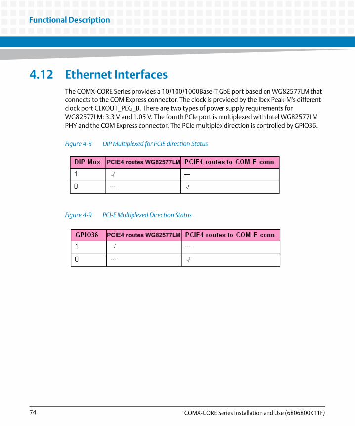
Functional Description
COMX-CORE Series Installation and Use (6806800K11F)74
4.12 Ethernet InterfacesThe COMX-CORE Series provides a 10/100/1000Base-T GbE port based on WG82577LM that connects to the COM Express connector. The clock is provided by the Ibex Peak-M's different clock port CLKOUT_PEG_B. There are two types of power supply requirements for WG82577LM: 3.3 V and 1.05 V. The fourth PCIe port is multiplexed with Intel WG82577LM PHY and the COM Express connector. The PCIe multiplex direction is controlled by GPIO36.
Figure 4-8 DIP Multiplexed for PCIE direction Status
Figure 4-9 PCI-E Multiplexed Direction Status

Functional Description
COMX-CORE Series Installation and Use (6806800K11F) 75
4.13 LPC InterfaceThe Low Pin Count (LPC) interface is routed to the connector and connects to the Super I/O, Trusted Platform Module (TPM), and the Firmware Hub (FWH) on the carrier board. The LPC clock with 33 MHz, which routes to the COM Express connector, can be used for Super I/O.
4.14 TPMCOMX-CORE-312/512 (ECC) supports an Infineon TPM1.2 chip on board. The Infineon SLB 9635 TT 1.2 Trusted Platform Module (TPM) provides computer manufacturers with the core components of a subsystem used to assure authenticity, integrity and confidentiality in e-commerce transactions and Internet communications.
Figure 4-10 WG82577LM Connection Diagram

Functional Description
COMX-CORE Series Installation and Use (6806800K11F)76
4.15 SPI InterfaceCOMX-CORE Series uses SPI flash as a boot device. On COM Express Type 6, the SPI bus routes to the COM Express connector. There is also a SPI BIOS on the carrier board, so the BIOS_DISABLE# signal from the carrier board is used. If you want to use the FWH on the carrier board, you must have a jumper on the carrier board switched to the BIOS source through the carrier board.
Table 4-8 SPI Multiplex Direction Status
BIOS_DISABLE0/1_N Boot from Module Boot from Carrier Board
1 OK ---
0 --- OK
Figure 4-11 SPI Interface Diagram

Functional Description
COMX-CORE Series Installation and Use (6806800K11F) 77
4.16 Watchdog TimerCOMX-CORE Series implements the watchdog timer feature by W83627UHG chip on the carrier board.
4.17 Hardware Monitor
4.17.1 Voltage Monitor
COMX-CORE Series's power supply is from the COM Express connector, which is different from the carrier board's power plane. LM96080 will monitor the voltages on COMX-CORE Series: CPU_VCORE, VCC_GFXCORE, VTT1_05, VCC1_05, DDR1V5, VCC3, VCC5.
4.17.2 Temperature
COMX-CORE Series uses W83627UHG to monitor the system temperature.
4.17.3 Fan Monitor and Control
COMX-CORE Series uses W83627UHG to monitor the system fan speed and the module fan speed.
4.18 AudioIbex Peak-M supports a high definition audio interface. The audio CODEC should be on the carrier board. The signals of HDA are routed to the COM Express connector directly.
4.19 Power ManagementCOMX-CORE Series supports ACPI S0, S3, S4 and S5.

Functional Description
COMX-CORE Series Installation and Use (6806800K11F)78
4.20 Real-time Clock (RTC)COMX-CORE Series supports a battery-backed real-time clock. The chipset Ibex Peak-M contains a Motorola MC146818A-compatible real-time clock with 256 bytes of battery-backed RAM. The real-time clock performs two key functions: keeping track of the time of day and storing system data, even when the system is powered down. The RTC operates on a 32.768 KHz crystal and a 3 V battery.
The RTC also supports two lockable memory ranges. By setting bits in the configuration space, two 8-byte ranges can be locked to read and write accesses. This prevents unauthorized reading of passwords or other system security information.
The RTC also supports a data alarm that allows for scheduling a wake up event up to 30 days in advance, rather than just 24 hours in advance.
Chapter 5
COMX-CORE Series Installation and Use (6806800K11F) 79
BIOS
5.1 POSTAfter power-up or reset, the BIOS performs a self-test, POST, that attempts to determine if further operation is possible and that the detected configuration is expected. This process can complete normally or result in a warning or an error. The boot process does not stop after a warning but displays a message on the primary display device. If an error is detected, the boot process is halted. If possible, a message will be displayed but failures early on in the test can only be indicated in POST codes.
The POST process display depends on the Quiet Boot option.
Viewing all checkpoints generated by Aptio firmware requires a checkpoint card, which is also named "POST Card" or "POST Diagnostic Card". They are PCI or LPC add-in cards that show the value of I/O port 80h on a LED display. These cards are available at the electronic or computer market around the world.
5.2 Boot ProcessWhile performing the functions of the traditional BIOS, Aptio 4.x core follows the firmware model described by the Intel Platform Innovation Framework for EFI ("the Framework"). The framework is associated to the following "boot phases", which can be described by various state code.
Security (SEC) - initial low-level initialization
Pre-EFI Initialization (PEI) - memory initialization1
Driver Execution Environment (DXE) - main hardware initialization2
Boot Device Selection (BDS) - system setup, pre-OS user interface & selecting a bootable device (CD/DVD, HDD, USB, Network, Shell, etc.)
5.3 Initiating SetupDuring the boot, pressing the 'F2' key on the keyboard requests the Setup utility be launched once the self-test is complete and before searching for a boot device. See the Setup description later in this document to describe the operation of this utility. If you exit Setup without saving any changes, the boot process continues with the search for a boot device. If the changes are saved, the motherboard loads the new settings and resets - re-starting the entire boot process.

BIOS
COMX-CORE Series Installation and Use (6806800K11F)80
5.4 Setup UtilityThe BIOS incorporates a Setup utility that allows the user to alter a variety of system options. This section describes the operation of the utility by describing the various options available through a set of hierarchical menus. Not all options are available with all products and some depend on BIOS customizations.
The current settings are stored in the SPI FLASH NVRAM area and any changes can be copied back to this area via the Exit menu. The operation of the BIOS defaults is described later in this document.
To start the utility, you must press the F2 key during the early stages of POST after power-up. Note that this functionality operates with PS/2 keyboards, USB keyboards when enabled, and via the console redirection facility when enabled.
The table below briefly describes the primary menus, most of which have sub-menus. The following sections describe the menus in detail.
Table 5-1 BIOS Primary Menu
Menu Options
Main BIOS information and date and time
Advanced Advanced features including ACPI, CPU, IDE, USB, HW monitoring and Serial Port settings
Chipset Features including Host Bridge and Southbridge
Boot Boot mode and Boot options
Security Administrator's password
Save & Exit Save with or without changes, Load/save default settings and Boot Device Selection

BIOS
COMX-CORE Series Installation and Use (6806800K11F) 81
The Aptio navigation can be accomplished using a combination of the keys. These keys include the <FUNCTION> keys, <ENTER>, <ESC>, <ARROW> keys, and so on.
Table 5-2 Aptio Navigation
Key Description
ENTER The Enter key allows the user to select an option to edit its value or access a sub menu.
Left/Right The Left and Right <Arrow> keys allow you to select a screen.
Up/Down The Up and Down <Arrow> keys allow you to select an item or sub-screen.
+- Plus/Minus The Plus and Minus <Arrow> keys allow you to change the field value of a particular setup item.
Tab The <Tab> key allows you to select fields.
ESC The <Esc> key allows you to discard any changes you have made and exit the Aptio Setup.When you are in sub-menu, <Esc> allows you to exit to the upper menu.
Function keys When other function keys become available, they are displayed at the right of the screen along with their intended function.

BIOS
COMX-CORE Series Installation and Use (6806800K11F)82
5.4.1 Main Menu
Figure 5-1 Main Menu
Table 5-3 Main Menu Field Description
Field Description
BIOS Vendor BIOS vendor name
Core Version Aptio core version
Project Version Project name and its version
Build Date BIOS build date

BIOS
COMX-CORE Series Installation and Use (6806800K11F) 83
System Date Sets the time and date (month/day/year format). To change these values, go to each field and enter the desired value. Press the tab key to move from hour to minute to second, or from month to day to year. There is no default value.
System Time
Table 5-4 Platform Information
Field Description
Processor Type CPU manufacturer brand
EMT64 Extended memory 64 technology
Processor Speed CPU current frequency
Processor Stepping CPU chip version
Processor Core CPU core number
Hyper-Threading Hyper-Threading technology
IGD VBIOS Version Integrated Graphic Drive Video BIOS version
QPI Frequency Quick Path Interconnect frequency
Total Memory All memory size
Memory Slot1 Slot1 memory size
Memory Slot2 Slot2 memory size
PCH Version Chipset version
Table 5-3 Main Menu Field Description (continued)
Field Description

BIOS
COMX-CORE Series Installation and Use (6806800K11F)84
5.4.2 Advanced Menu
Figure 5-2 Advanced Menu
Table 5-5 Advanced Menu Field Description
Field Description
PCI Subsystem Settings PCI Configuration Parameters, see PCI Subsystem Settings
ACPI Settings System ACPI Parameters, see ACPI Settings

BIOS
COMX-CORE Series Installation and Use (6806800K11F) 85
Trusted Computing Trusted Computing Module for security purpose, see Trusted Computing
S5 RTC Wake Settings Enables system to wake from S5 using RTC alarm, see S5 RTC Wake Settings
CPU Configuration CPU Configuration Parameters, see CPU Configuration
ME Configuration See ME Configurations
Thermal Configuration See Thermal Configuration
Port 80h Port 80h PEIM, see Port 80h
USB Configuration USB Configuration Parameters, see USB Configuration
AMT Configuration AMT Configuration, see AMT Configuration
LM80 H/W Monitor Monitor hardware, see LM80 Hardware Monitor
Super IO Configuration System Super IO chip Parameters, see Super IO Configuration
W83627UHG H/W Monitor
Monitor hardware, see W83627UHG Hardware Monitor
Serial Port Console Redirection
Serial Port Console Redirection, see Serial Port Console Redirection
Table 5-6 PCI Subsystem Settings
Field Description
PCI ROM Priority In case of multiple Option ROMs (Legacy and EFI Compatible), specifies what PCI Option rom to launch. Default is EFI Compatible ROMs
PCI Latency Timer Value to be programmed into PCI Latency Timer Register.Default is 32 PCI Bus Clocks
Table 5-7 ACPI Settings
Field Description
Enable ACPI Auto Configuration
Enables or Disables BIOS ACPI Auto Configuration. Default is Disabled.
Table 5-5 Advanced Menu Field Description (continued)
Field Description

BIOS
COMX-CORE Series Installation and Use (6806800K11F)86
ACPI Sleep State Select the highest ACPI sleep state the system will enter, when the SUSPEND button is pressed. States: Suspend Disabled,S1(CPU Stop Clock) and S3 (Suspend to RAM). Default is S3(Suspend to RAM).
S3 Video Repost If enabled, Video Option ROM will be dispatched during S3 resume. Default is Disabled.
Table 5-8 Trusted Computing
Field Description
TPM SUPPORT Enables or Disables TPM function. Default is Disabled. When the item is disabled in BIOS, OS will not show TPM.
TPM State Turns the TPM On/Off.Changing the TPM state needs a computer restart. Default is Disabled.
Pending TPM operation Schedule TPM operationDefault is none.
Current TPM Status Information
NO TPM Hardware If no TPM is found
TPM Enabled Status: Shows TPM status: Enabled or Disabled
TPM Active Status: Shows current state of the TPM: Activated or Deactivated
TPM Owner Status: Shows current TPM Ownership state. ie: Owned or UnOwned
Table 5-9 S5 RTC Wake Settings
Field Description
Wake system with Fixed Time
Enable or disable System wake on alarm eventWhen enabled, system will wake on the hr::min::sec specified.Default is Disabled
Wake up hour Select 0-23. Example: enter 3 for 3am and 15 for 3pmDefault is 0
Table 5-7 ACPI Settings (continued)
Field Description

BIOS
COMX-CORE Series Installation and Use (6806800K11F) 87
Wake up minute 0 - 59Default is 0
Wake up second 0 - 59Default is 0
Wake System with Dynamic Time
Enable or disable System wake on alarm event. When enabled, the system will wake on current time + Increase minute(s). Default is Disabled.
Wake up minute increase Range 1 - 5
Table 5-10 CPU Configuration
Field Description
Power & Performance Power & Performance options
Hyper-Threading Enabled for Windows XP and Linux (OS optimized for Hyper-Threading Technology) and Disabled for other OS (OS not optimized for Hyper-Threading Technology).Default is Enabled.
Active Processor Cores Number of cores to enable for each processor packageDefault is All
Intel Virtualization When enabled, a VMM can utilize the additional hardware capabilities provided by Vanderpool Technology
Intel Trusted Execution Technology
Enables utilization of additional hardware capabilities provided by Intel Trusted Execution Technology. Changes require a full power cycle to take effect. Default is Disable
Table 5-11 ME Configurations
Field Description
ME FW Version ME Firmware Version
ME Firmware ME FW SKU
Table 5-9 S5 RTC Wake Settings (continued)
Field Description

BIOS
COMX-CORE Series Installation and Use (6806800K11F)88
Table 5-12 Thermal Configuration
Field Description
CPU Thermal Configuration CPU thermal configuration, see CPU Thermal Configuration
Table 5-13 CPU Thermal Configuration
Field Description
TM1 Enable/Disable Thermal Monitor1; Default is Enabled
TM2 Enable/Disable Thermal Monitor2; Default is Enabled
ACPI 3.0 T-States Enable/Disable ACPI 3.0 T-States ;Default is Disabled
Table 5-14 Port 80h
Field Description
Port 80h Redirection Control where the Port 80h cycles are sent: PCI bus, LPC bus Default is LPC bus
Table 5-15 USB Configuration
Field Description
USB Devices List the USB Devices attached.
Legacy USB Support Enables Legacy USB support. AUTO option disables legacy support if no USB devices are connected. DISABLE option will keep USB devices available only for EFI applications. Default is Enabled.
Device Reset Timeout USB mass storage device Start Unit command timeoutItems: 10 sec,20 sec,30 sec,40 secDefault is 20 sec.
Table 5-16 AMT Configuration
Field Description
Intel AMT Enable/Disable Intel Active Management Technology BIOS ExtensionDefault is Enabled.

BIOS
COMX-CORE Series Installation and Use (6806800K11F) 89
Intel AMT Setup Prompt Enable/Disable Intel AMT Setup Prompt to wait for hot-key to enter setup.Default is Enabled.
ASF Enable/Disable Alert Standard Format.Default is Enabled.
Un-Configure ME Un-Configure ME without password.Default is Disabled.
Hide Un-Configure ME Hide Un-Configure ME without password confirmation prompt.Default is Disabled.
Table 5-17 LM80 Hardware Monitor
Field Description
CPU_VCORE Monitor the core voltage of CPU
VCC_GFXCORE Monitor the core voltage of GFX
VTT1_05 Monitor VTT 1.05V
VCC1_05 Monitor VCC 1.05V
DDR1V5 Monitor 1.5V for DDR3 RAM
VCC3 Monitor VCC 3.3V on Module board
VCC5 Monitor VCC 5.0V on Module board
Table 5-18 Super IO Configuration
Field Description
Super IO Chip Usually Winbond W83627UHG
Serial Port 1 Configuration Set Parameters of Serial Port 1 (COMA), see Serial Port 1/2/3/4/5/6 Configuration
Serial Port 2 Configuration Set Parameters of Serial Port 2 (COMB), see Serial Port 1/2/3/4/5/6 Configuration
Serial Port 3 Configuration Set Parameters of Serial Port 3 (COMC), see Serial Port 1/2/3/4/5/6 Configuration
Table 5-16 AMT Configuration (continued)
Field Description

BIOS
COMX-CORE Series Installation and Use (6806800K11F)90
Serial Port 4 Configuration Set Parameters of Serial Port 4 (COMD), see Serial Port 1/2/3/4/5/6 Configuration
Serial Port 5 Configuration Set Parameters of Serial Port 5 (COME), see Serial Port 1/2/3/4/5/6 Configuration
Serial Port 6 Configuration Set Parameters of Serial Port 6 (COMF), see Serial Port 1/2/3/4/5/6 Configuration
Parallel Port Configuration Set Parameters of Parallel Port (LPT/LPTE), see Serial Port 1/2/3/4/5/6 Configuration
Watchdog Timer Configuration Set parameters of Watchdog Timer (WDT), see Watchdog Timer Configuration
Intrusion Detect Select state for Intrusion DetectDefault is Disabled
Table 5-19 Serial Port 1/2/3/4/5/6 Configuration
Field Description
Serial Port Enable/Disable Serial PortDefault is Enabled
Device Settings Current settings: IO=3F8; IRQ=4;1
Change Settings Select an optimal setting for Super IO DeviceOptions:Auto IO=3F8h; IRQ=4;IO=3F8h; IRQ=3,4,5,6,7,10,11,12;IO=2F8h; IRQ=3,4,5,6,7,10,11,12;IO=3E8h; IRQ=3,4,5,6,7,10,11,12;IO=2E8h; IRQ=3,4,5,6,7,10,11,12;Default is Auto.
1. IO address shall be assigned responding to various Serial Ports. For example, IO=2F8; IRQ=3 for COMB, IO=3E8; IRQ=7 for COMC, IO=2E8; IRQ=7 for COMD, IO=2E0; IRQ=10 for COME, IO=2F0; IRQ=10 for COMF.
Table 5-18 Super IO Configuration (continued)
Field Description

BIOS
COMX-CORE Series Installation and Use (6806800K11F) 91
Table 5-20 Parallel Port Configuration
Field Description
Parallel Port Enable/Disable Parallel Port (LPT/LPTE)Default is Enabled
Change Settings Select an optimal setting for Super IO DeviceItems:Auto IO=378h; IRQ=5;IO=378h; IRQ=5,6,7,10,11,12;IO=278h; IRQ=5,6,7,10,11,12;IO=3BCh; IRQ=5,6,7,10,11,12;IO=378h;IO=278h;IO=3BCh;Default is Auto.
Device Mode Change the Printer Port modeItems: STD Printer ModeSPP ModeEPP-1.9 and SPP ModeEPP-1.7 and SPP ModeECP ModeECP and EPP 1.9 ModeECP and EPP 1.7 Mode
Table 5-21 Watchdog Timer Configuration
Field Description
Watchdog Timer Select an optimal Watchdog Timer setting (WDT)Default is Disabled
Table 5-22 W83627UHG Hardware Monitor
Field Description
Module Temperature Module temperature
Module Fan Speed Module fan speed
System Temperature System temperature
System Fan Speed System fan speed

BIOS
COMX-CORE Series Installation and Use (6806800K11F)92
VCC3 Monitor VCC 3.3V on carrier board
VCC5 Monitor VCC 5.0V on carrier board
VCC12 Monitor VCC 12V
Table 5-23 Serial Port Console Redirection
Field Description
COM1: Console Redirection Enable/Disable console redirectionDefault is Enabled
COM1: Console Redirection Settings
See COM 1/2 Console Redirection Settings
COM2: Console Redirection Enable/Disable console redirectionDefault is Disabled
COM2: Console Redirection Settings
See COM 1/2 Console Redirection Settings
COM4 (Pci Dev22, Func3): Console Redirection
Enable/Disable console redirectionDefault is Disabled
COM4: Console Redirection Settings
See COM 1/2 Console Redirection Settings
Serial Port for OBM/EMS: Console Redirection
Enable/Disable console redirection for OBM/EMS usageDefault is Disabled
Out-of-Band Mgnt Port Default is COM1
Table 5-24 COM 1/2 Console Redirection Settings
Field Description
Terminal Type Emulation: ANSI: Extended ASCII char set. VT100: ASCII char set. VT100+: Extends VT100 to support color, functional keys, etc. VT-UTF8: Uses UTF8 encoding to map unicode chars onto 1 or more bytes. Default is VT100.
Table 5-22 W83627UHG Hardware Monitor (continued)
Field Description

BIOS
COMX-CORE Series Installation and Use (6806800K11F) 93
Bits per second Selects serial port transmission speedThe speed must be matched on the other side. Long or noisy lines may require lower speeds. Options: 9600, 19200, 57600, 115200. Default is 115200.
Data Bits Data BitsItems: 7,8Default is 8
Parity A parity bit can be sent with the data bits to detect some transmission errors. Even: parity bit is 0 if the num of 1's in the data bits is even. Odd: parity bit is 0 if num of 1's in the data bits is odd. Mark: parity bit is always 1. Space: Parity bit is always 0. Mark and space parity do not allow for error detection. They can be used as an additional data bit. Options: None, Even, Odd, Mark, SpaceDefault is None
Stop Bits Stop bits indicate the end of a serial data packet. (A start bit indicates the beginning). The standard setting is 1 stop bit. Communication with slow devices may require more than 1 stop bit. Options: 1, 2. Default is 1.
Flow Control Flow control can prevent data loss from buffer overflow. When sending data, if the receiving buffers are full, a 'stop' signal can be sent to stop the data flow. Once the buffers are empty, a 'start' signal can be sent to restart the flow. Hardware flow control uses two wires to send start/stop signals. Software flow control uses start/stop ASCII chars, which slows down the data flow and can be problematic if binary data is being sent. Options: None, Hardware RTS/CTS. Default is None.
Resolution 100x31 Enable or disable extended terminal resolution. Default is Disabled.
Legacy OS Redirection Options: 80x25, 80x24. Default is 80x24.
Table 5-24 COM 1/2 Console Redirection Settings (continued)
Field Description

BIOS
COMX-CORE Series Installation and Use (6806800K11F)94
5.4.3 Chipset Menu
Figure 5-3 Chipset Menu
Table 5-25 Chipset Menu Description
Field Description
North Bridge Configuration North Bridge Parameters, see North Bridge Configuration
South Bridge Configuration South Bridge Parameters, see South Bridge Configuration

BIOS
COMX-CORE Series Installation and Use (6806800K11F) 95
Table 5-26 North Bridge Configuration
Field Description
Common Northbridge Control
Control various common Northbridge functions, See Common Northbridge Control
Arrandale_Clarkdale Arrandale options, See Arrandale_Clarkdale
Arrandale_Clarkdale MRC/QPI
Arrandale MRC options, See Arrandale_Clarkdale MRC/QPI
Primary Display Select which of IGD/PEG graphics device should be primary displayOptions: Auto, IGD, PEGDefault is Auto
Table 5-27 Common Northbridge Control
Field Description
PEG Port Configuration PEG Port options, see PEG Port Configuration
VT-d Check to enable VT-d function on MCHDefault is Disabled
Table 5-28 PEG Port Configuration
Field Description
Always Enable PEG enables the PEG slotDefault is Disabled
Force X1 Force PEG link to retrain to X1 modeDefault is Disabled
Table 5-29 Arrandale_Clarkdale
Field Description
IGD-LCD Control See IGD - LCD Control

BIOS
COMX-CORE Series Installation and Use (6806800K11F)96
Table 5-30 IGD - LCD Control
Field Description
DVMT Pre-Allocated Select DVMT 5.0 Pre-allocated (fixed) graphics memory size used by the Internal Graphics Device. Options: 32M, 64M, 128M. Default is 32M.
DVMT Total Gfx Mem Select DVMT5.0 total graphic memory size used by the Internal Graphics Device. Options: 128M, 256M, MAX. Default is 256M.
IGD - Boot Type Select the video device which will be activated during POST. This has no effect if external graphics is present.Options: VBIOS Default, CRT, LVDS, CRT + LVDS, HDMI, CRT + HDMI, DP1, DP2Default is CRT + LVDS.
LCD Panel Type Select LCD panel with an appropriate setting. Options: VBIOS Default, 800x600 LVDS, 1024x768 LVDS, 1280x1024 LVDS , 1400x1050 LVDS1, 1400x1050 LVDS2,1600x1200 LVDS, 1280x768 LVDS, 1680x1050 LVDS, 1920x1200 LVDS, 1600x900 LVDS, 1280x800 LVDS, 1280x600 LVDS, 2048x1536 LVDS.Default is CRT+LVDS, 1024x768 LVDS
Please be aware that selecting an incompatinle setting may cause problems for the display.
Panel Scaling Select the LCD panel scaling option used by the Internal Graphics Device. Options: Auto, Force Scaling, Off, Maintain Aspect Ratio. Default is Auto.
Backlight Control Backlight control setting. Options: PWM Inverted, PWM Normal, GMBus Inverted, GMBus Normal. Default is PWM Inverted.
Spread Spectrum clock chip
>>Hardware: Spread is controlled by chip>>Software: Spread is controlled by BIOSOptions: Off, Hardware, SoftwareDefault is Off
Panel Color Depth Select the LFP Panel Color DepthOptions: 18bit, 24bitDefault is 24bit

BIOS
COMX-CORE Series Installation and Use (6806800K11F) 97
Table 5-31 Arrandale_Clarkdale MRC/QPI
Field Description
QPI Frequency Quick path interface frequency Options: Auto, 3200 GT, 4800 GT, 5866 GT, 6400 GT, DisabledDefault is Auto
Memory Frequency Maximum memory frequency Options: Auto, 800, 1066Default is Auto.
Table 5-32 South Bridge Configuration
Field Description
IbexPeak options See IbexPeak Options
USB Configuration See USB Configuration
SATA Configuration See SATA Configuration
Table 5-33 IbexPeak Options
Field Description
PCH LAN Controller Enable/Disable onboard NICDefault is Enabled
Wake on LAN Enable Enable/Disable integrated LAN to wake the system.Default is Enabled
PXE ROM Enable/Disable PXE option ROM execution for onboard LAN. Default is Disabled.
Azalia Control detection of the Azalia device.Disabled = Azalia will be unconditionally disabledEnabled = Azalia will be unconditionally Enabled
Auto = Azalia will be enabled if present, disabled otherwise. Default is Auto.
Azalia internal HDM Enable/Disable internal HDMI codec for Azalia. Default is Enabled.
Clock Spread Spectrum Enable Clock chip's Spread Spectrum feature. Default is Disabled.

BIOS
COMX-CORE Series Installation and Use (6806800K11F)98
State After G3 Specify what state to go to when power is re-applied after a power failure (G3 state). Options: S0 State, S5 State. Default is S5 State.
Table 5-34 USB Configuration
Field Description
EHCI1 Controls the USB EHCI (USB2.0) functionsOne EHCI controller must always be enabled. EHCI1 is in charge of six USB ports (J14, J15, P2).
EHCI2 Controls the USB EHCI (USB2.0) functionsOne EHCI controller must always be enabled. EHCI2 is in charge of 3 USB ports (P1, P39, P3).
Table 5-35 SATA Configuration
Field Description
SATA Controller(s) Enable/Disable SATA Device.
Default is Enabled.
COMX-CORE-510/710/750 supports SATA 1,2,3,4
COMX-CORE -312/512 supports SATA 1,2,5,6
SATA Mode Selection Determines how SATA Controller(s) operate.
Default is IDE.
Software Feature Mask Configuration will be shown as well. Refer to Table 5-36
Serial ATA Port1/2/3/4 SATA Port1/2/3/4 State
Table 5-36 Software Feature Mask Configuration
Field Description
RAID0 Enable/Disable RAID0 feature
RAID1 Enable/Disable RAID1 feature
Table 5-33 IbexPeak Options (continued)
Field Description

BIOS
COMX-CORE Series Installation and Use (6806800K11F) 99
RAID10 Enable/Disable RAID10 feature
RAID5 Enable/Disable RAID5 feature
Intel Rapid Recovery Technology
Enable/Disable Intel Rapid Recovery Technology
Table 5-36 Software Feature Mask Configuration (continued)
Field Description

BIOS
COMX-CORE Series Installation and Use (6806800K11F)100
5.4.4 Boot Menu
Figure 5-4 Boot Menu
Table 5-37 Boot Menu Field Description
Field Description
Quiet Boot Enables/Disables quiet boot option. Default is Disabled.

BIOS
COMX-CORE Series Installation and Use (6806800K11F) 101
5.4.4.1 Quiet Boot Option
After power-up or reset, POST is performed. The POST process display depends on the Quiet Boot option, which is followed with a prompt 'Press <DEL> or <F2> to enter setup. Press <F7> for BBS POPUP Menu'.
Setup Prompt Timeout Number of seconds to wait for setup activation key. 65535(0xFFFF) means indefinite waiting. 0 means no wait (not recommended).Default is 2.
Bootup NumLock State Select the keyboard NumLock state. Items: On, Off. Default is On.
Option ROM Messages Set display mode for Option ROM. Items: Force BIOS, Keep Current. Default is Force BIOS.
Boot Option Priorities Set the system boot order.
CD/DVD ROM Drive BBS Priorities
Sets the order of the legacy devices in this group.
Hard Drive BBS Priorities Sets the order of the legacy devices in this group.
Table 5-37 Boot Menu Field Description (continued)
Field Description

BIOS
COMX-CORE Series Installation and Use (6806800K11F)102
5.4.5 Security Menu
Figure 5-5 Security Menu
Table 5-38 Security Menu Field Description
Field Description
Setup Administrator Password
Sets the setup administrator password.
User Password Sets the setup user password.

BIOS
COMX-CORE Series Installation and Use (6806800K11F) 103
5.4.6 Save and Exit Menu
Figure 5-6 Save and Exit Menu
Table 5-39 Save and Exit Menu Field Description
Field Description
Save Changes and Exit Exit system setup after saving the changes.
Discard Changes and Exit Exit system setup without saving any changes.
Save Changes and Reset Reset the system after saving the changes.
Discard Changes and Reset
Reset system setup without saving any changes.

BIOS
COMX-CORE Series Installation and Use (6806800K11F)104
5.5 ACPI Wake Up Support Matrix
5.6 Default Boot SequenceThe default boot order is as follows:
1. USB - from eUSB Flash, USB Flash thumb-drive, USB CD/DVD
2. SATA - SATA HDD, CD/DVD
3. PXE Network Boot - Local Ethernet Controller
Save Changes Save Changes made so far to any of the setup options.
Discard Changes Save Changes done so far to any of the setup options.
Restore Defaults Restore/Load Defaults values for all the setup options.
Save as User Defaults Save the changes done so far as User Defaults.
Restore User Defaults Restore the User Defaults to all the setup options.
Boot Override The options will override the boot orders in 'Boot' menu. So you can freely select the device which you want to boot.
Launch EFI Shell from filesystem device
Attempts to Launch EFI Shell application (Shellx64.efi) from one of the available filesystem devices.
Table 5-39 Save and Exit Menu Field Description (continued)
Field Description
Table 5-40
Power Button PS2 KB/MS USB KB/MS Onboard LAN
S3 Yes Yes Yes Yes
S4 Yes No No Yes
S5 Yes No No Yes

BIOS
COMX-CORE Series Installation and Use (6806800K11F) 105
5.7 POST Codes
5.7.1 Status Code Ranges
5.7.2 Standard Status Codes
5.7.2.1 SEC Status Codes
Table 5-41 Status Code Ranges
Status Code Range Description
0x01 - 0x0F SEC Status Codes & Errors
0x10 - 0x2F PEI execution up to and including memory detection
0x30 - 0x4F PEI execution after memory detection
0x50 - 0x5F PEI errors
0x60 - 0xCF DXE execution up to BDS
0xD0 - 0xDF DXE errors
0xE0 - 0xE8 S3 Resume (PEI)
0xE9 - 0xEF S3 Resume errors (PEI)
0xF0 - 0xF8 Recovery (PEI)
0xF9 - 0xFF Recovery errors (PEI)
Table 5-42 SEC Status Codes
Status Code Description
0x0 Not used
Progress Codes

BIOS
COMX-CORE Series Installation and Use (6806800K11F)106
5.7.2.2 PEI Status Codes
0x1 Power on. Reset type detection (soft/hard).
0x2 AP initialization before microcode loading
0x3 North Bridge initialization before microcode loading
0x4 South Bridge initialization before microcode loading
0x5 OEM initialization before microcode loading
0x6 Microcode loading
0x7 AP initialization after microcode loading
0x8 North Bridge initialization after microcode loading
0x9 South Bridge initialization after microcode loading
0xA OEM initialization after microcode loading
0xB Cache initialization
SEC Error Codes
0xC - 0xD Reserved for future AMI SEC error codes
0xE Microcode not found
0xF Microcode not loaded
Table 5-42 SEC Status Codes (continued)
Status Code Description
Table 5-43 PEI Status Codes
Status Code Description
Progress Codes
0x10 PEI Core is started
0x11 Pre-memory CPU initialization is started
0x12 CPU pre-memory initialization (CPU module specific)
0x13 CPU pre-memory initialization (CPU module specific)
0x14 CPU pre-memory initialization (CPU module specific)

BIOS
COMX-CORE Series Installation and Use (6806800K11F) 107
0x15 Pre-memory North Bridge initialization is started
0x16 Pre-Memory North Bridge initialization (North Bridge module specific)
0x17 Pre-Memory North Bridge initialization (North Bridge module specific)
0x18 Pre-Memory North Bridge initialization (North Bridge module specific)
0x19 Pre-memory South Bridge initialization is started
0x1A Pre-memory South Bridge initialization (South Bridge module specific)
0x1B Pre-memory South Bridge initialization (South Bridge module specific)
0x1C Pre-memory South Bridge initialization (South Bridge module specific)
0x1D - 0x2A OEM pre-memory initialization codes
0x2B Memory initialization. Serial Presence Detect (SPD) data reading
0x2C Memory initialization. Memory presence detection
0x2D Memory initialization. Programming memory timing information
0x2E Memory initialization. Configuring memory
0x2F Memory initialization (other).
0x30 Reserved for ASL (see ASL Status Codes section below)
0x31 Memory Installed
0x32 CPU post-memory initialization is started
0x33 CPU post-memory initialization. Cache initialization
0x34 CPU post-memory initialization. Application Processor(s) (AP) initialization
0x35 CPU post-memory initialization. Boot Strap Processor (BSP) selection
0x36 CPU post-memory initialization. System Management Mode (SMM) initialization
Table 5-43 PEI Status Codes (continued)
Status Code Description

BIOS
COMX-CORE Series Installation and Use (6806800K11F)108
0x37 Post-Memory North Bridge initialization is started
0x38 Post-Memory North Bridge initialization (North Bridge module specific)
0x39 Post-Memory North Bridge initialization (North Bridge module specific)
0x3A Post-Memory North Bridge initialization (North Bridge module specific)
0x3B Post-Memory South Bridge initialization is started
0x3C Post-Memory South Bridge initialization (South Bridge module specific)
0x3D Post-Memory South Bridge initialization (South Bridge module specific)
0x3E Post-Memory South Bridge initialization (South Bridge module specific)
0x3F-0x4E OEM post memory initialization codes
0x4F DXE IPL is started
PEI Error Codes
0x50 Memory initialization error. Invalid memory type or incompatible memory speed
0x51 Memory initialization error. SPD reading has failed
0x52 Memory initialization error. Invalid memory size or memory modules do not match.
0x53 Memory initialization error. No usable memory detected
0x54 Unspecified memory initialization error.
0x55 Memory not installed
0x56 Invalid CPU type or Speed
0x57 CPU mismatch
0x58 CPU self test failed or possible CPU cache error
0x59 CPU micro-code is not found or micro-code update is failed
0x5A Internal CPU error
Table 5-43 PEI Status Codes (continued)
Status Code Description

BIOS
COMX-CORE Series Installation and Use (6806800K11F) 109
0x5B reset PPI is not available
0x5C-0x5F Reserved for future AMI error codes
S3 Resume Progress Codes
0xE0 S3 Resume is stared (S3 Resume PPI is called by the DXE IPL)
0xE1 S3 Boot Script execution
0xE2 Video repost
0xE3 OS S3 wake vector call
0xE4-0xE7 Reserved for future AMI progress codes
0xE0 S3 Resume is stared (S3 Resume PPI is called by the DXE IPL)
S3 Resume Error Codes
0xE8 S3 Resume Failed in PEI
0xE9 S3 Resume PPI not Found
0xEA S3 Resume Boot Script Error
0xEB S3 OS Wake Error
0xEC-0xEF Reserved for future AMI error codes
Recovery Progress Codes
0xF0 Recovery condition triggered by firmware (Auto recovery)
0xF1 Recovery condition triggered by user (Forced recovery)
0xF2 Recovery process started
0xF3 Recovery firmware image is found
0xF4 Recovery firmware image is loaded
0xF5 - 0xF7 Reserved for future AMI progress codes
Recovery Error Codes
0xF8 Recovery PPI is not available
0xF9 Recovery capsule is not found
0xFA Invalid recovery capsule
0xFB - 0xFF Reserved for future AMI error codes
Table 5-43 PEI Status Codes (continued)
Status Code Description

BIOS
COMX-CORE Series Installation and Use (6806800K11F)110
5.7.2.3 PEI Beep Codes
5.7.2.4 DXE Status Codes
Table 5-44 PEI Beep Codes
# of Beeps Description
1 Memory not Installed
1 Memory was installed twice (InstallPeiMemory routine in PEI Core called twice)
3 DXEIPL was not found
3 DXE Core Firmware Volume was not found
7 Reset PPI is not available
4 Recovery failed
4 S3 Resume failed
Table 5-45 DXE Status Codes
Status Code Description
0x60 DXE Core is started
0x61 NVRAM initialization
0x62 Installation of the South Bridge Runtime Services
0x63 CPU DXE initialization is started
0x64 CPU DXE initialization (CPU module specific)
0x65 CPU DXE initialization (CPU module specific)
0x66 CPU DXE initialization (CPU module specific)
0x67 CPU DXE initialization (CPU module specific)
0x68 PCI host bridge initialization
0x69 North Bridge DXE initialization is started

BIOS
COMX-CORE Series Installation and Use (6806800K11F) 111
0x6A North Bridge DXE SMM initialization is started
0x6B North Bridge DXE initialization (North Bridge module specific)
0x6C North Bridge DXE initialization (North Bridge module specific)
0x6D North Bridge DXE initialization (North Bridge module specific)
0x6E North Bridge DXE initialization (North Bridge module specific)
0x6F North Bridge DXE initialization (North Bridge module specific)
0x70 South Bridge DXE initialization is started
0x71 South Bridge DXE SMM initialization is started
0x72 South Bridge devices initialization
0x73 South Bridge DXE Initialization (South Bridge module specific)
0x74 South Bridge DXE Initialization (South Bridge module specific)
0x75 South Bridge DXE Initialization (South Bridge module specific)
0x76 South Bridge DXE Initialization (South Bridge module specific)
0x77 South Bridge DXE Initialization (South Bridge module specific)
0x78 ACPI module initialization
0x79 CSM initialization
0x7A - 0x7F Reserved for future AMI DXE codes
0x80 - 0x8F OEM DXE initialization codes
0x90 Boot Device Selection (BDS) phase is started
0x91 Driver connecting is started
0x92 PCI Bus initialization is started
0x93 PCI Bus Hot Plug Controller Initialization
0x94 PCI Bus Enumeration
0x95 PCI Bus Request Resources
0x96 PCI Bus Assign Resources
0x97 Console Output devices connect
0x98 Console input devices connect
Table 5-45 DXE Status Codes (continued)
Status Code Description

BIOS
COMX-CORE Series Installation and Use (6806800K11F)112
0x99 Super IO Initialization
0x9A USB initialization is started
0x9B USB Reset
0x9C USB Detect
0x9D USB Enable
0x9E - 0x9F Reserved for future AMI codes
0xA0 Reserved for ASL (see ASL Status Codes section below)
0xA1 IDE initialization is started
0xA2 IDE Reset
0xA3 IDE Detect
0xA4 IDE Enable
0xA5 SCSI initialization is started
0xA6 SCSI Reset
0xA7 SCSI Detect
0xA8 SCSI Enable
0xA9 Setup Verifying Password
0xAA Reserved for ASL (see ASL Status Codes section below)
0xAB Start of Setup
0xAC Setup Input Wait
0xAD Ready To Boot event
0xAE Legacy Boot event
0xAF Exit Boot Services event
0xB0 Runtime Set Virtual Address MAP Begin
0xB1 Runtime Set Virtual Address MAP End
0xB2 Legacy Option ROM Initialization
0xB3 System Reset
0xB4 USB hot plug
Table 5-45 DXE Status Codes (continued)
Status Code Description

BIOS
COMX-CORE Series Installation and Use (6806800K11F) 113
5.7.2.5 DXE Beep Codes
0xB5 PCI bus hot plug
0xB6 Clean-up of NVRAM
0xB7 Configuration Reset (reset of NVRAM settings)
0xB8 - 0xBF Reserved for future AMI codes
0xC0 - 0xCF OEM BDS initialization codes
DXE Error Codes
0xD0 CPU initialization error
0xD1 North Bridge initialization error
0xD2 South Bridge initialization error
0xD3 Some of the Architectural Protocols are not available
0xD4 PCI resource allocation error. Out of Resources
0xD5 No Space for Legacy Option ROM
0xD6 No Console Output Devices are found
0xD7 No Console Input Devices are found
0xD8 Invalid password
0xD9 Error loading Boot Option (LoadImage returned error)
0xDA Boot Option is failed (StartImage returned error)
0xDB Flash update is failed
0xDC Reset protocol is not available
Table 5-45 DXE Status Codes (continued)
Status Code Description
Table 5-46 DXE Beep Codes
# of Beeps Description
4 Some of the Architectural Protocols are not available
5 No Console Output Devices are found

BIOS
COMX-CORE Series Installation and Use (6806800K11F)114
5.7.2.6 CPU Exception Status Codess
5 No Console Input Devices are found
1 Invalid password
6 Flash update is failed
7 Reset protocol is not available
Table 5-46 DXE Beep Codes (continued)
# of Beeps Description
Table 5-47 CPU Exception Status Codes
Status Code Description
0x00 Divide error
0x01 CPU Debug exception
0x02 Non maskable hardware Interrupt occurred
0x03 INT 3 breakpoint
0x04 Overflow, INT 0 instruction
0x05 Bound Range Exceeded
0x06 Invalid Opcode (undefined Opcode)
0x07 Device Not Available ( No Math Co-Processor)
0x08 Double Fault. Any instruction to the CPU that can Generate an NMI or INTR
0x09 Co-Processor Segment Overrun
0x0A Invalid Task Switch Access
0x0B Segment not present. Occurs after a load segment
0x0C Stack Segment Fault. Relations to Stack operations
0x0D General Protection fault. Any memory reference and other protection checks
0x0E Page Fault.
0x0F Reserved by Intel

BIOS
COMX-CORE Series Installation and Use (6806800K11F) 115
5.7.2.7 ASL Status Codes
0x10 Floating Point Error
0x11 Alignment Check
0x12 Machine Check
0x13 SIMD Floating point exception
Table 5-47 CPU Exception Status Codes (continued)
Status Code Description
Table 5-48 ASL Status Codes
Status Code Description
0x01 System is entering S1 sleep state
0x02 System is entering S2 sleep state
0x03 System is entering S3 sleep state
0x04 System is entering S4 sleep state
0x05 System is entering S5 sleep state
0x10 System is waking up from the S1 sleep state
0x20 System is waking up from the S2 sleep state
0x30 System is waking up from the S3 sleep state
0x40 System is waking up from the S4 sleep state
0xAC System has transitioned into ACPI mode. Interrupt controller is in PIC mode.
0xAA System has transitioned into ACPI mode. Interrupt controller is in APIC

BIOS
COMX-CORE Series Installation and Use (6806800K11F)116
5.7.2.8 OEM-reserved Status Code Ranges
Table 5-49 OEM-reserved Status Code Ranges
Status Code Description
0x5 OEM SEC initialization before microcode loading
0xA OEM SEC initialization after microcode loading
0x1D - 0x2A OEM pre-memory initialization codes
0x3F - 0x4E OEM PEI post memory initialization codes
0x80 - 0x8F OEM DXE initialization codes
0xC0 - 0xCF OEM BDS initialization codes

Chapter 6
COMX-CORE Series Installation and Use (6806800K11F) 117
Operating System and Driver Support
6.1 Supported Operating SystemsThis module supports the following operating systems:
Microsoft Window XP
RHEL 5.x / Fedora 11
6.2 Supported Drivers
Table 6-1 Driver Controller Table
XP32 XP64 Embedded Vista32 Vista64 Fedora
Chipset Yes Yes Yes Yes Yes TBD
Graphic Yes Yes Yes Yes Yes TBD
LAN Yes Yes Yes Yes Yes TBD
Audio Yes Yes Yes Yes Yes Yes
ME Yes Yes Yes Yes Yes TBD
RAID/AHCI Yes Yes Yes Yes Yes TBD

Operating System and Driver Support
COMX-CORE Series Installation and Use (6806800K11F)118

Appendix A
COMX-CORE Series Installation and Use (6806800K11F) 119
A Related Documentation
A.1 Artesyn Embedded Technologies - Embedded Computing DocumentationThe publications listed below are referenced in this manual. You can obtain electronic copies of Artesyn Embedded Technologies - Embedded Computing publications by contacting your local Artesyn sales office. For released products, you can also visit our Web site for the latest copies of our product documentation.
1. Go to www.artesyn.com/computing.
2. Under SUPPORT, click TECHNICAL DOCUMENTATION.
3. Under FILTER OPTIONS, click the Document types drop-down list box to select the type of document you are looking for.
4. In the Search text box, type the product name and click GO.
Table A-1 Artesyn Embedded Technologies - Embedded Computing Publications
Document Title Publication Number
COMX-CORE Series Quick Start Guide 6806800K13
COMX-CORE Series Release Notes 6806800K91
COMX-CORE Series Safety Notes 6806800K12
COMX-CAR-610 Installation and Use 6806800K26
COMX-CAR-610 Quick Start Guide 6806800K27
COMX-CAR-610 Safety Notes 6806800K28

Related Documentation
COMX-CORE Series Installation and Use (6806800K11F)120

COMX-CORE Series Installation and Use (6806800K11F) 121
Safety Notes
This section provides warnings that precede potentially dangerous procedures throughout this manual. Instructions contained in the warnings must be followed during all phases of operation, service, and repair of this equipment. You should also employ all other safety precautions necessary for the operation of the equipment in your operating environment. Failure to comply with these precautions or with specific warnings elsewhere in this manual could result in personal injury or damage to the equipment.
Artesyn intends to provide all necessary information to install and handle the product in this manual. Because of the complexity of this product and its various uses, we do not guarantee that the given information is complete. If you need additional information, ask your Artesyn representative.
The product has been designed to meet the standard industrial safety requirements. It must only be used in its specific area of office telecommunication industry, industrial control, and development. It must not be used in safety critical components, life supporting devices or on aircraft.
Only personnel trained by Artesyn or persons qualified in electronics or electrical engineering are authorized to install, remove or maintain the product. The information given in this manual is meant to complete the knowledge of a specialist and must not be used as replacement for qualified personnel.
Keep away from live circuits inside the equipment. Operating personnel must not remove equipment covers. Only factory authorized service personnel or other qualified service personnel is allowed to remove equipment covers for internal subassembly or component replacement or any internal adjustment.
This product operates with dangerous voltages that can cause injury or death. Use extreme caution when handling, testing, and adjusting this equipment and its components.
Operation
Product DamageHigh humidity and condensation on surfaces cause short circuits. Do not operate the product outside the specified environmental limits. Make sure the product is completely dry and there is no moisture on any surface before applying power.

COMX-CORE Series Installation and Use (6806800K11F)
Safety Notes
122
Installation
Damage of CircuitsElectrostatic discharge and incorrect installation and removal of the product can damage circuits or shorten their life.Before touching the product make sure that your are working in an ESD-safe environment or wear an ESD wrist strap or ESD shoes. Hold the product by its edges and do not touch any components or circuits.
Damage of the Product and Additional Devices and ModulesIncorrect installation or removal of additional devices or modules damages the product or the additional devices or modules.Before installing or removing additional devices or modules, read the respective documentation and use appropriate tools.
Pin DamageForcing the module into the system may damage connector pins. If the module hangs during insertion, pull it out and insert it again.
Environment
Environmental DamageImproperly disposing of used products may harm the environment.Always dispose of used products according to your country’s legislation and manufacturer’s instructions.

COMX-CORE Series Installation and Use (6806800K11F) 123
Sicherheitshinweise
Dieses Kapitel enthält Hinweise, die potentiell gefährlichen Prozeduren innerhalb dieses Handbuchs vorrangestellt sind. Beachten Sie unbedingt in allen Phasen des Betriebs, der Wartung und der Reparatur des Systems die Anweisungen, die diesen Hinweisen enthalten sind. Sie sollten außerdem alle anderen Vorsichtsmaßnahmen treffen, die für den Betrieb des Systems innerhalb Ihrer Betriebsumgebung notwendig sind. Wenn Sie diese Vorsichtsmaßnahmen oder Sicherheitshinweise, die an anderer Stelle diese Handbuchs enthalten sind, nicht beachten, kann das Verletzungen oder Schäden am System zur Folge haben.
Artesyn ist darauf bedacht, alle notwendigen Informationen zum Einbau und zum Umgang mit dem System in diesem Handbuch bereit zu stellen. Da es sich jedoch bei dem System um ein komplexes Produkt mit vielfältigen Einsatzmöglichkeiten handelt, können wir die Vollständigkeit der im Handbuch enthaltenen Informationen nicht garantieren. Falls Sie weitere Informationen benötigen sollten, wenden Sie sich bitte an die für Sie zuständige Geschäftsstelle von Artesyn.
Das Produkt erfüllt die für die Industrie geforderten Sicherheitsvorschriften und darf ausschließlich für Anwendungen in der Telekommunikationsindustrie, im Zusammenhang mit Industriesteuerungen und in der Entwicklung verwendet werden. Es darf nicht in sicherheitskritischen Anwendungen, lebenserhaltenden Geräten oder in Flugzeugen verwendet werden.
Einbau, Wartung und Betrieb dürfen nur von durch Artesyn ausgebildetem oder im Bereich Elektronik oder Elektrotechnik qualifiziertem Personal durchgeführt werden. Die in diesem Handbuch enthaltenen Informationen dienen ausschließlich dazu, das Wissen von Fachpersonal zu ergänzen, können dieses jedoch nicht ersetzen.
Halten Sie sich von stromführenden Leitungen innerhalb des Systems fern. Entfernen Sie auf keinen Fall die Systemabdeckung. Nur werksseitig zugelassenes Wartungspersonal oder anderweitig qualifiziertes Wartungspersonal darf die Systemabdeckung entfernen, um Systemkomponenten zu ersetzen oder andere Anpassungen vorzunehmen.
Installieren Sie keine Ersatzteile oder führen Sie keine unerlaubten Veränderungen am System durch, sonst verfällt die Garantie. Wenden Sie sich für Wartung oder Reparatur bitte an die für Sie zuständige Geschäftsstelle von Artesyn Embedded Technologies. So stellen Sie sicher, dass alle sicherheitsrelevanten Aspekte beachtet werden.

COMX-CORE Series Installation and Use (6806800K11F)
Sicherheitshinweise
124
Artesyn und unsere Zulieferer unternehmen größte Anstrengungen um sicherzustellen, dass sich Pins und Stecker von Boards vor dem Verlassen der Produktionsstätte in einwandfreiem Zustand befinden. Verbogene Pins, verursacht durch fehlerhafte Installation oder durch Installation von Boards mit beschädigten Steckern kann die durch Artesyn gewährte Garantie für Boards und Backplanes erlöschen lassen.
Dieses Produkt wird mit gefährlichen Spannungen betrieben, die zu Verletzungen und Tod führen können. Seien Sie im Umgang mit dem Produkt und beim Testen und Anpassen des Produktes und seiner Komponenten äußerst vorsichtig.
Betrieb
Beschädigung des SystemsHohe Luftfeuchtigkeit und Kondensat auf den Oberflächen der Produkte kann zu Kurzschlüssen führen. Betreiben Sie die Produkte nur innerhalb der angegebenen Grenzwerte für die relative Luftfeuchtigkeit und Temperatur und stellen Sie vor dem Einschalten des Stroms sicher, dass sich auf den Produkten kein Kondensat befindet.
System Installation
Beschädigung von SchaltkreisenElektrostatische Entladung und unsachgemäßer Ein- und Ausbau des Produktes kann Schaltkreise beschädigen oder ihre Lebensdauer verkürzen.Bevor Sie das Produkt oder elektronische Komponenten berühren, vergewissern Sie sich, daß Sie in einem ESD-geschützten Bereich arbeiten.
Beschädigung des Produktes und der ZusatzmoduleFehlerhafter Ein- oder Ausbau von Zusatzmodulen führt zu Beschädigung des Produktes oder der Zusatzmodule. Lesen Sie deshalb vor dem Ein- oder Ausbau von Zusatzmodulen die Dokumentation und benutzen Sie angemessenes Werkzeug.

Sicherheitshinweise
COMX-CORE Series Installation and Use (6806800K11F) 125
Umweltschutz
UmweltverschmutzungFalsche Entsorgung der Produkte schadet der Umwelt.Entsorgen Sie alte Produkte gemäß der in Ihrem Land gültigen Gesetzgebung und den Empfehlungen des Herstellers.

COMX-CORE Series Installation and Use (6806800K11F)
Sicherheitshinweise
126


Artesyn Embedded Technologies, Artesyn and the Artesyn Embedded Technologies logo are trademarks and service marks of Artesyn Embedded Technologies, Inc.All other product or service names are the property of their respective owners.© 2014 Artesyn Embedded Technologies, Inc.
Related Documents