Computers and Chemical Engineering 59 (2013) 219–225 Contents lists available at ScienceDirect Computers and Chemical Engineering jo u r n al homep age: www.elsevier.com/locate/compchemeng Multi-scale modeling of Claus thermal furnace and waste heat boiler using detailed kinetics Flavio Manenti ∗ , Davide Papasidero, Alessio Frassoldati, Giulia Bozzano, Sauro Pierucci, Eliseo Ranzi Politecnico di Milano, Dipartimento di Chimica, Materiali e Ingegneria Chimica “Giulio Natta”, Piazza Leonardo da Vinci 32, 20133 Milano, Italy a r t i c l e i n f o Article history: Received 1 October 2012 Received in revised form 3 May 2013 Accepted 15 May 2013 Available online 14 June 2013 Keywords: Sulfur recovery Waste heat boiler Thermal furnace Partial oxidation Recombination effects Claus process a b s t r a c t The modeling of thermal reaction furnaces of Sulfur Recovery Units (SRUs) is a rather complex problem since it involves different modeling scales such as the kinetic/molecular scale, the reactor scale, and the chemical process scale. This work introduces the multi-scale modeling approach to characterize the kinetic and reaction engineering scales for the thermal section of SRUs, involving the reactor furnace and the waste heat boiler. Specifically, also the waste heat boiler is modeled using detailed kinetics to characterize the recombination effects, which cannot be neglected any longer since they significantly influence the outlet compositions. The proposed models are validated on experimental and literature data for the kinetic scale. The reactor scale is validated on the industrial data coming from SRUs operating in Nanjing and Mumbai plants. © 2013 Elsevier Ltd. All rights reserved. 1. Introduction Process simulation is nowadays supported by many tools and commercial flowsheeting packages involving unit operations, reac- tors, thermodynamic libraries, and property databases. These tools make possible the simulation of complex processes and overall plants, but they still have certain key open issues to be handled to perform accurate simulations and deepen the process under- standing. One of the hardest problems is the simulation of non-ideal reactors via detailed kinetic schemes. This lack in the current pro- cess simulators is mainly due to: (I) the need of complex and well-established kinetic schemes to characterize the reaction envi- ronment; (II) the need to face simulation issues at different scales (kinetic and plant scales); and (III) the need of powerful solvers to handle the resulting large-scale stiff nonlinear systems coming from kinetic modeling. The paper investigates the possibility to bridge the gap in process modeling by coupling DSmoke and BzzMath libraries to develop a multi-scale model useful to study and debottleneck issues at the process scale. DSmoke allows to simulate non-ideal reactors by solving complex networks of ideal elements and it is based on consolidated kinetic schemes (Ranzi, 2006). BzzMath library (Buzzi-Ferraris & Manenti, 2010a, 2012) is a numerical ∗ Corresponding author. Tel.: +39 02 2399 3273; fax: +39 02 7063 8173. E-mail address: fl[email protected] (F. Manenti). library for scientific computing. Specifically, it includes several solvers to handle numerical problems of different nature and can be integrated in commercial packages as discussed else- where (Manenti, Buzzi-Ferraris, Pierucci, Rovaglio, & Gulati, 2011; Manenti, Signor, Grottoli, & Fabbri, 2010; Signor, Manenti, Grottoli, Fabbri, & Pierucci, 2010; Manenti et al., 2013). For its apparent com- plexities as well as its renewed academic and industrial interest, the ideal field to apply the multi-scale model is the thermal reactor fur- nace of Sulfur Recovery Units (SRUs), which are aimed at removing sulfur from acid gas streams. Section 2 presents the kinetic model details with the comparison of model trends with respect to literature experimental data. Also, the main reactions are identified for each single reactor by means of sensitivity analyses. Section 3 shows the simulation of the pre- mixed laminar flame for the Claus furnace for the comprehensive validation of the kinetic model. Section 4 describes the reactor net- work adopted to simulate the industrial layout of Sulfur Recovery Units using the detailed kinetic model. 2. Kinetic scale The kinetics of thermal reaction furnace of SRUs is rather com- plex and not yet completely understood. The kinetics governing the transformations of sulfur compounds has been studied by Mueller, Yetter, and Dryer (2003), who described the main the oxi- dation mechanisms, and Dagaut, Lecomte, Mieritz, and Glarborg (1995), who highlighted the inhibition effects of SO 2 on the radical 0098-1354/$ – see front matter © 2013 Elsevier Ltd. All rights reserved. http://dx.doi.org/10.1016/j.compchemeng.2013.05.028

Welcome message from author
This document is posted to help you gain knowledge. Please leave a comment to let me know what you think about it! Share it to your friends and learn new things together.
Transcript
Mu
FEP
a
ARRAA
KSWTPRC
1
ctmptsrcwr(tf
pdiril
0h
Computers and Chemical Engineering 59 (2013) 219– 225
Contents lists available at ScienceDirect
Computers and Chemical Engineering
jo u r n al homep age: www.elsev ier .com/ locate /compchemeng
ulti-scale modeling of Claus thermal furnace and waste heat boilersing detailed kinetics
lavio Manenti ∗, Davide Papasidero, Alessio Frassoldati, Giulia Bozzano, Sauro Pierucci,liseo Ranzi
olitecnico di Milano, Dipartimento di Chimica, Materiali e Ingegneria Chimica “Giulio Natta”, Piazza Leonardo da Vinci 32, 20133 Milano, Italy
r t i c l e i n f o
rticle history:eceived 1 October 2012eceived in revised form 3 May 2013ccepted 15 May 2013vailable online 14 June 2013
a b s t r a c t
The modeling of thermal reaction furnaces of Sulfur Recovery Units (SRUs) is a rather complex problemsince it involves different modeling scales such as the kinetic/molecular scale, the reactor scale, andthe chemical process scale. This work introduces the multi-scale modeling approach to characterize thekinetic and reaction engineering scales for the thermal section of SRUs, involving the reactor furnaceand the waste heat boiler. Specifically, also the waste heat boiler is modeled using detailed kineticsto characterize the recombination effects, which cannot be neglected any longer since they significantly
eywords:ulfur recoveryaste heat boiler
hermal furnaceartial oxidationecombination effects
influence the outlet compositions. The proposed models are validated on experimental and literature datafor the kinetic scale. The reactor scale is validated on the industrial data coming from SRUs operating inNanjing and Mumbai plants.
© 2013 Elsevier Ltd. All rights reserved.
laus process
. Introduction
Process simulation is nowadays supported by many tools andommercial flowsheeting packages involving unit operations, reac-ors, thermodynamic libraries, and property databases. These tools
ake possible the simulation of complex processes and overalllants, but they still have certain key open issues to be handledo perform accurate simulations and deepen the process under-tanding. One of the hardest problems is the simulation of non-idealeactors via detailed kinetic schemes. This lack in the current pro-ess simulators is mainly due to: (I) the need of complex andell-established kinetic schemes to characterize the reaction envi-
onment; (II) the need to face simulation issues at different scaleskinetic and plant scales); and (III) the need of powerful solverso handle the resulting large-scale stiff nonlinear systems comingrom kinetic modeling.
The paper investigates the possibility to bridge the gap inrocess modeling by coupling DSmoke and BzzMath libraries toevelop a multi-scale model useful to study and debottleneck
ssues at the process scale. DSmoke allows to simulate non-ideal
eactors by solving complex networks of ideal elements and its based on consolidated kinetic schemes (Ranzi, 2006). BzzMathibrary (Buzzi-Ferraris & Manenti, 2010a, 2012) is a numerical∗ Corresponding author. Tel.: +39 02 2399 3273; fax: +39 02 7063 8173.E-mail address: [email protected] (F. Manenti).
098-1354/$ – see front matter © 2013 Elsevier Ltd. All rights reserved.ttp://dx.doi.org/10.1016/j.compchemeng.2013.05.028
library for scientific computing. Specifically, it includes severalsolvers to handle numerical problems of different nature andcan be integrated in commercial packages as discussed else-where (Manenti, Buzzi-Ferraris, Pierucci, Rovaglio, & Gulati, 2011;Manenti, Signor, Grottoli, & Fabbri, 2010; Signor, Manenti, Grottoli,Fabbri, & Pierucci, 2010; Manenti et al., 2013). For its apparent com-plexities as well as its renewed academic and industrial interest, theideal field to apply the multi-scale model is the thermal reactor fur-nace of Sulfur Recovery Units (SRUs), which are aimed at removingsulfur from acid gas streams.
Section 2 presents the kinetic model details with the comparisonof model trends with respect to literature experimental data. Also,the main reactions are identified for each single reactor by meansof sensitivity analyses. Section 3 shows the simulation of the pre-mixed laminar flame for the Claus furnace for the comprehensivevalidation of the kinetic model. Section 4 describes the reactor net-work adopted to simulate the industrial layout of Sulfur RecoveryUnits using the detailed kinetic model.
2. Kinetic scale
The kinetics of thermal reaction furnace of SRUs is rather com-plex and not yet completely understood. The kinetics governing
the transformations of sulfur compounds has been studied byMueller, Yetter, and Dryer (2003), who described the main the oxi-dation mechanisms, and Dagaut, Lecomte, Mieritz, and Glarborg(1995), who highlighted the inhibition effects of SO2 on the radical
220 F. Manenti et al. / Computers and Chemical Engineering 59 (2013) 219– 225
Fo
pdOPm
t4tsthofiikad
2
tHtaBf
H
H
Agwi
TR
F
Table 2Inlet conditions for the reacting systems.
Inlet composition – Case 1, without S2 Inlet composition – Case 2, with S2
H2S 0.05 mol/mol H2S 0.0333 mol/molS2 0.00 mol/mol S2 0.0167 mol/molAr 0.95 mol/mol Ar 0.95 mol/mol
From Binoist et al. (2003).
the formation of new elemental sulfur (Figs. 3 and 4). From a generalpoint of view, the model response is less accurate than the Binoist’smodel, but it is important to say that the presence of hydrocarbons
ig. 1. Pyrolysis (data and reactor: Binoist et al., 2003): H2S conversion in absencef S2.
ool. The pyrolysis of hydrogen sulfide, H2S, has been defined inetail by different authors (Binoist et al., 2003; Glassmann, 1996).ther authors (Clark, Dowling, Huang, Svrcek, & Monnery, 2001;etherbridge et al., 2003) focused their research on the formationechanisms of a specific species such as the CS2 and the COS.The collection of the literature data, the experimental and indus-
rial campaigns led to a kinetic model for sulfur compounds with0 molecular and radical species and almost 150 reactions. In addi-ion, since the combustion in the thermal section of SRUs is usuallyupplied with fuel to sustain the flame and keep the chamber athe desired temperature, the kinetic model of sulfur compoundsas been combined with the kinetic model for the characterizationf pyrolysis and oxidation of light hydrocarbons (Ranzi, 2006). Thenal kinetic model consists of 146 species and 2412 reactions. For
ts dimensions, it is not possible to report it completely, but theey-reactions of all the kinetic mechanisms for sulfur compoundsre identified by means of a series of sensitivity analyses and deeplyiscussed.
.1. H2S pyrolysis
Beyond the relevance of sulfur oxides generated in the combus-ion of fossil fuels and of the emissions of SRUs, the importance of2S pyrolysis is progressively increasing since it plays a key-role in
he formation of the radical pool especially at the lean combustionir conditions of thermal reactor furnaces of SRUs. According to theinoist’s reactor and conditions (Binoist et al., 2003) the initial steps
or the H2S pyrolysis are:
2S + M = SH + H + M (1)
2S + M = H2 + S + M (2)
selection of model predictions related to the reactions above is
iven in Figs. 1–4. The reactor configuration is presented in Table 1,hereas the inlet conditions for the two simulations are reportedn Table 2.
able 1eactor configuration.
Reactor configuration and operating conditionsReactor type Isothermal CSTRResidence time 0.4–1.6 s (variable)Temperature 800–1100 ◦C (variable)Pressure 1.0 atm
rom Binoist et al. (2003).
Fig. 2. Pyrolysis (data and reactor: Binoist et al., 2003): H2S conversion in presenceof S2.
The pyrolysis of H2S is significant over 850 ◦C, achieving almosta 50% conversion at 1050 ◦C (Fig. 1). The kinetic model slightlyunderestimates the conversion at the high temperatures, whereasit overestimates the conversion at relatively low temperatures. Thisis a typical bell-like behavior due to the value of activation energiesof the kinetic expressions constituting the pyrolysis mechanisms.This deviation is more apparent in the trends of Fig. 2, where thepyrolysis of H2S is favored in presence of elemental sulfur. At rela-tively low temperature the presence of sulfur allotropes, which arenot considered in the model, could play an important role in fittingthe data. The presence of sulfur and its effects on H2S pyrolysis areof particular importance in the thermal reactor furnaces of SRUs,where the partial oxidation of the acid gas leads to a certain amountof elemental sulfur already within the furnace. Although the pyrol-ysis of H2S is improved, the presence of sulfur unavoidably reduces
Fig. 3. Pyrolysis (data and reactor: Binoist et al., 2003): formation of elemental sulfurin absence of S2.

F. Manenti et al. / Computers and Chemical Engineering 59 (2013) 219– 225 221
Fi
ac
2
mocS
2
w(dcetfr
seif
S
O
S
CieAtr
S
S
Ssr
P
240
200
160
120
80
40
0220 260 300 340
Pres
sure
(Tor
r)
Slow oxida�on
Evalu a�on o f the second limit
Explosi on
Igni �on
ig. 4. Pyrolysis (data and reactor: Binoist et al., 2003): formation of elemental sulfurn presence of S2.nd oxygen for partial oxidation, typical conditions of SRU furnacesan significantly affect the behavior of the overall system.
.2. H2S oxidation
Under the combustion regime of Claus furnaces the inlet H2S andercaptans are partially (one third) oxidized to SO2. The partial
xidation allows to achieve the optimal ratio H2S/SO2 = 2 at theatalytic reactors (Claus converters) to maximize the yield of theRU according to the overall Claus reaction:
H2S + SO2 = 3/xSx + 2H2O (3)
here x indicates the presence of allotropes and their equilibriax = 1, 2, 4, 6, 8), and thus to maximize the sequestration and pro-uction of the elemental sulfur. More details on the Claus processan be found elsewhere (Manenti, Grottoli, & Pierucci, 2011; Signort al., 2010). The oxidation of sulfur compound can be brought backo the H2S explosion diagram, which was experimentally analyzedor the first time by Jacovlev and Schantarovitsch (1937) and theneconsidered by Cullis and Mulcahy (1972) and Glassmann (1996).
According to Farkas (1931), the explosion limit at high pres-ure is related to the reactor diameter and therefore to the heatxchange with the external environment. The sensitivity analysisn correspondence with the slow-oxidation region highlighted theollowing predominant reactions sorted by relevance:
H + O2 + M = HSO2 + M (4)
2 + H2S = HO2 + SH (5)
O + O2 = SO2 + O (6)
onversely, in the explosion region, the reaction (6) is the mostmportant one. The second limit in the explosion diagram is gov-rned by the competition of chain branching and chain termination.t relatively low temperatures, SH radicals react with O2 according
o the following competing (low and high pressures, respectively)eactions:
H + O2 = SO + OH (7)
H + O2 + M = HSO2 + M (8)
ince this limit defines the passage from the low to the high pres-ure mechanisms, it can be determined by the calculating the ratio
7/r4 = 1 that describes the transition from such mechanisms:(T) = r7
r4= ˛7[SH][O2]exp(−E7/RT)
˛4[SH][O2](P/RT)exp(−E4/RT)(9)
Temperatu re ( °C)
Fig. 5. Explosion diagram of H2S.
Thus, considering the respective kinetic parameters, it is possibleto evaluate dashed profile in the explosion diagram:
P(T) = r7
r4= 1010[SH][O2]exp(−12, 350/RT)
3 × 10⁸[SH][O2]P/RT(10)
P(T) = ˛7
˛4exp
(E4 − E7
RT
)RT = 1010
3 × 10⁸exp
(−12, 350
1.986T
)64.2T
(11)
which is in good agreement with the literature diagram (solid line)reported in Fig. 5 and compared with the explosion diagram of H2S.The sensitivity analysis performed for the upper limit showed thatthe reaction (6) in the ignition region is comparable to reaction(4) in the oxidation region. Conversely, in the ignition zone, thefollowing reactions are relevant:
SH + O2 = HSO + O (12)
H2S + SO = S2O + H2 (13)
The low pressure limit has poor practical relevance (there are notindustrial application at 0.01 atm) and it is not considered in thiswork.
2.3. The role of SO2 in kinetic mechanisms
It is worth underlining that the oxidation process of H2S gener-ates SO2 as predominant product:
2H2S + 3O2 = 2H2O + SO2 (14)
SO2 is also active in many kinetic mechanisms and in particular itassumes a relevant role in the formation of SO3, as described byMueller et al. (2003) and summarized in the key reactions here-inafter:
SO2 + O + M = SO3 + M (15)
SO2 + OH + M = HOSO2 + M (16)
HOSO2 + O = SO3 + OH (17)
Nevertheless, such a mechanism is rather inhibited in the thermalreactor furnace due to the non-stoichiometric conditions of com-bustion air. Also due to these nominal conditions, SO2 can promoteor inhibit several other mechanisms. For instance, it is a radical
222 F. Manenti et al. / Computers and Chemical Engineering 59 (2013) 219– 225
0
0,001
0,002
0,003
0,004
0,005
0,006
0 500 1000
Sp
ec
ies
Mo
le F
rac
tio
n
Initial SO2 Mole Fraction (PPM)
SO2 Effects on CO oxidation
Exp. Data, O2
Exp. Data, CO
Exp. Data, CO2
Model, O2
Model, CO
Model, CO2
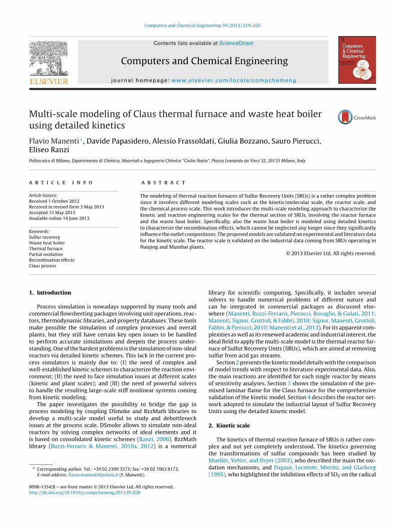
Fig. 6. Inhibition effects of SO2 on the oxidation of CO (data and reactor information:Ma0
psitatmpsg
2
Cehtmt
FDaSf1
0
0,002
0,004
0,006
0,008
0,01
0,012
800 1000 1200 1400
CO
Mo
le F
racti
on
T (K)
Effects of SO2 on CO oxidation
Exp. Data, WithSO2
Exp. Data,Without SO2
Model, WithSO2
Model, WithoutSO2
Fig. 8. Inhibition effects of SO2 on the oxidation of CO (data and reactor information:Dagaut et al., 1995; P = 1 atm, T = 800–1400 K; tau = 192.7/T; reactor diam. = 0.9 cm;absolute tolerance 1e−12; reactor type: isothermal PFR; inlet mole fractions without
ueller et al., 2003; P = 3 atm; T = 1020 K; tau = 0.52 s; reactor diameter = 10.16 cm;bsolute tolerance 1e−10; reactor type: 1-D adiabatic PFR; inlet mole fractions CO.50%, H2O 0.6%, O2 0.25%, SO2 0–1300 ppm, N2 balance).
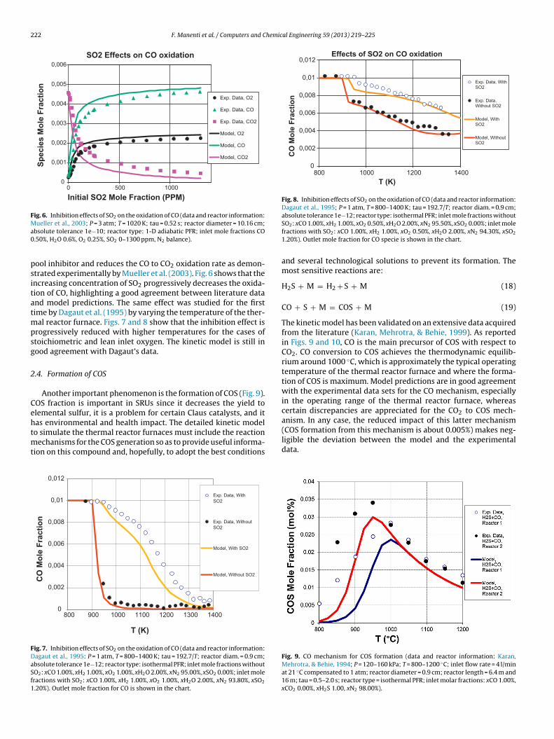
ool inhibitor and reduces the CO to CO2 oxidation rate as demon-trated experimentally by Mueller et al. (2003). Fig. 6 shows that thencreasing concentration of SO2 progressively decreases the oxida-ion of CO, highlighting a good agreement between literature datand model predictions. The same effect was studied for the firstime by Dagaut et al. (1995) by varying the temperature of the ther-
al reactor furnace. Figs. 7 and 8 show that the inhibition effect isrogressively reduced with higher temperatures for the cases oftoichiometric and lean inlet oxygen. The kinetic model is still inood agreement with Dagaut’s data.
.4. Formation of COS
Another important phenomenon is the formation of COS (Fig. 9).OS fraction is important in SRUs since it decreases the yield tolemental sulfur, it is a problem for certain Claus catalysts, and itas environmental and health impact. The detailed kinetic model
o simulate the thermal reactor furnaces must include the reactionechanisms for the COS generation so as to provide useful informa-ion on this compound and, hopefully, to adopt the best conditions
0
0,002
0,004
0,006
0,008
0,01
0,012
800 900 1000 1100 1200 1300 1400
CO
Mo
le F
rac
tio
n
T (K)
Exp. Data, With
SO2
Exp. Data, Without
SO2
Model, With SO2
Model, Without SO2
ig. 7. Inhibition effects of SO2 on the oxidation of CO (data and reactor information:agaut et al., 1995: P = 1 atm, T = 800–1400 K; tau = 192.7/T; reactor diam. = 0.9 cm;bsolute tolerance 1e−12; reactor type: isothermal PFR; inlet mole fractions withoutO2: xCO 1.00%, xH2 1.00%, xO2 1.00%, xH2O 2.00%, xN2 95.00%, xSO2 0.00%; inlet moleractions with SO2: xCO 1.00%, xH2 1.00%, xO2 1.00%, xH2O 2.00%, xN2 93.80%, xSO2
.20%). Outlet mole fraction for CO is shown in the chart.
SO2: xCO 1.00%, xH2 1.00%, xO2 0.50%, xH2O 2.00%, xN2 95.50%, xSO2 0.00%; inlet molefractions with SO2: xCO 1.00%, xH2 1.00%, xO2 0.50%, xH2O 2.00%, xN2 94.30%, xSO2
1.20%). Outlet mole fraction for CO specie is shown in the chart.
and several technological solutions to prevent its formation. Themost sensitive reactions are:
H2S + M = H2 + S + M (18)
CO + S + M = COS + M (19)
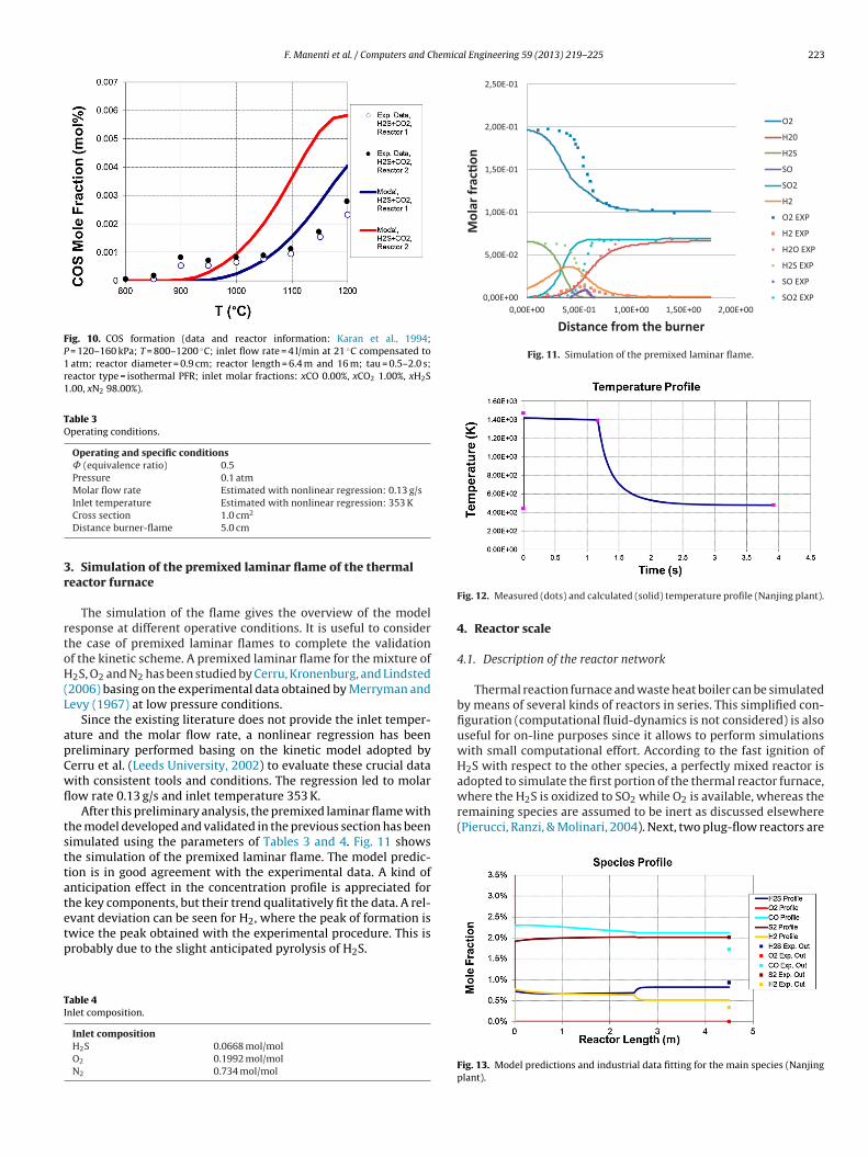
The kinetic model has been validated on an extensive data acquiredfrom the literature (Karan, Mehrotra, & Behie, 1999). As reportedin Figs. 9 and 10, CO is the main precursor of COS with respect toCO2. CO conversion to COS achieves the thermodynamic equilib-rium around 1000 ◦C, which is approximately the typical operatingtemperature of the thermal reactor furnace and where the forma-tion of COS is maximum. Model predictions are in good agreementwith the experimental data sets for the CO mechanism, especiallyin the operating range of the thermal reactor furnace, whereascertain discrepancies are appreciated for the CO2 to COS mech-anism. In any case, the reduced impact of this latter mechanism
(COS formation from this mechanism is about 0.005%) makes neg-ligible the deviation between the model and the experimentaldata.Fig. 9. CO mechanism for COS formation (data and reactor information: Karan,Mehrotra, & Behie, 1994; P = 120–160 kPa; T = 800–1200 ◦C; inlet flow rate = 4 l/minat 21 ◦C compensated to 1 atm; reactor diameter = 0.9 cm; reactor length = 6.4 m and16 m; tau = 0.5–2.0 s; reactor type = isothermal PFR; inlet molar fractions: xCO 1.00%,xCO2 0.00%, xH2S 1.00, xN2 98.00%).
F. Manenti et al. / Computers and Chemical Engineering 59 (2013) 219– 225 223
Fig. 10. COS formation (data and reactor information: Karan et al., 1994;P = 120–160 kPa; T = 800–1200 ◦C; inlet flow rate = 4 l/min at 21 ◦C compensated to1 atm; reactor diameter = 0.9 cm; reactor length = 6.4 m and 16 m; tau = 0.5–2.0 s;reactor type = isothermal PFR; inlet molar fractions: xCO 0.00%, xCO2 1.00%, xH2S1.00, xN2 98.00%).
Table 3Operating conditions.
Operating and specific conditions˚ (equivalence ratio) 0.5Pressure 0.1 atmMolar flow rate Estimated with nonlinear regression: 0.13 g/s
3r
rtoH(L
apCwfl
tsttatetp
TI
0,00E+00
5,00E-02
1,00E-01
1,50E-01
2,00E-01
2,50E-01
0,00E+00 5, 00E-01 1, 00E+00 1, 50E+00 2, 00E+00
Mol
ar fr
ac�o
n
Distance from th e burn er
O2
H20
H2S
SO
SO2
H2
O2 EXP
H2 EXP
H2O EXP
H2S EXP
SO EXP
SO2 EXP
Fig. 11. Simulation of the premixed laminar flame.
adopted to simulate the first portion of the thermal reactor furnace,where the H2S is oxidized to SO2 while O2 is available, whereas theremaining species are assumed to be inert as discussed elsewhere(Pierucci, Ranzi, & Molinari, 2004). Next, two plug-flow reactors are
Inlet temperature Estimated with nonlinear regression: 353 KCross section 1.0 cm2
Distance burner-flame 5.0 cm
. Simulation of the premixed laminar flame of the thermaleactor furnace
The simulation of the flame gives the overview of the modelesponse at different operative conditions. It is useful to considerhe case of premixed laminar flames to complete the validationf the kinetic scheme. A premixed laminar flame for the mixture of2S, O2 and N2 has been studied by Cerru, Kronenburg, and Lindsted
2006) basing on the experimental data obtained by Merryman andevy (1967) at low pressure conditions.
Since the existing literature does not provide the inlet temper-ture and the molar flow rate, a nonlinear regression has beenreliminary performed basing on the kinetic model adopted byerru et al. (Leeds University, 2002) to evaluate these crucial dataith consistent tools and conditions. The regression led to molarow rate 0.13 g/s and inlet temperature 353 K.
After this preliminary analysis, the premixed laminar flame withhe model developed and validated in the previous section has beenimulated using the parameters of Tables 3 and 4. Fig. 11 showshe simulation of the premixed laminar flame. The model predic-ion is in good agreement with the experimental data. A kind ofnticipation effect in the concentration profile is appreciated forhe key components, but their trend qualitatively fit the data. A rel-
vant deviation can be seen for H2, where the peak of formation iswice the peak obtained with the experimental procedure. This isrobably due to the slight anticipated pyrolysis of H2S.able 4nlet composition.
Inlet compositionH2S 0.0668 mol/molO2 0.1992 mol/molN2 0.734 mol/mol
Fig. 12. Measured (dots) and calculated (solid) temperature profile (Nanjing plant).
4. Reactor scale
4.1. Description of the reactor network
Thermal reaction furnace and waste heat boiler can be simulatedby means of several kinds of reactors in series. This simplified con-figuration (computational fluid-dynamics is not considered) is alsouseful for on-line purposes since it allows to perform simulationswith small computational effort. According to the fast ignition ofH2S with respect to the other species, a perfectly mixed reactor is
Fig. 13. Model predictions and industrial data fitting for the main species (Nanjingplant).
224 F. Manenti et al. / Computers and Chemical Engineering 59 (2013) 219– 225
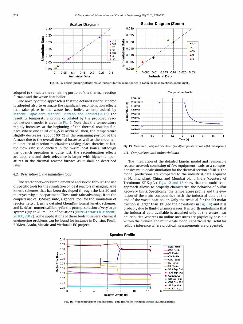
the main species (a zoom for small fractions, on the right).
af
itMrtrnsfmttaal
4
okmcras2eR
Fig. 14. Residuals (Nanjing plant); molar fractions for
dopted to simulate the remaining portion of the thermal reactionurnace and the waste heat boiler.
The novelty of the approach is that the detailed kinetic schemes adopted also to estimate the significant recombination effectshat take place in the waste heat boiler, as emphasized by
anenti, Papasidero, Manenti, Bozzano, and Pierucci (2012). Theesulting temperature profile calculated by the proposed reac-or network model is given in Fig. 5. Note that the temperatureapidly increases at the beginning of the thermal reaction fur-ace where one third of H2S is oxidized; then, the temperaturelightly decreases (about 100 ◦C) in the remaining portion of theurnace due to the overall thermal losses as well as the endother-
ic nature of reaction mechanisms taking place therein; at last,he flow rate is quenched in the waste heat boiler. Althoughhe quench operation is quite fast, the recombination effectsre apparent and their relevance is larger with higher temper-tures in the thermal reactor furnace as it shall be describedater.
.2. Description of the simulation tools
The reactor network is implemented and solved through the usef specific tools for the simulation of ideal reactors managing largeinetic schemes that has been developed through the last 20 andore years by our department. These tools take advantage from the
oupled use of DSMoke suite, a general tool for the simulation ofeactor network using detailed ChemKin-format kinetic schemes,nd BzzMath numerical library for the prompt solution of very large
ystems (up to 40 million of equations (Buzzi-Ferraris & Manenti,010b, 2012). Some applications of these tools to several chemicalngineering problems can be found for instance in Dynsim, Pro/II,OMeo, Acado, Mosaic, and Virthualis EC project.Fig. 16. Model previsions and industrial data fit
Fig. 15. Measured (dots) and calculated (solid) temperature profile (Mumbai plant).
4.3. Comparison with industrial data
The integration of the detailed kinetic model and reasonablereactor network consisting of few equipment leads to a compre-hensive multi-scale simulation for the thermal section of SRUs. Themodel predictions are compared to the industrial data acquiredat Nanjing plant, China, and Mumbai plant, India (courtesy ofTecnimont-KT S.p.A.). Figs. 12 and 13 show that the multi-scaleapproach allows to properly characterize the behavior of SulfurRecovery Units. Specifically, the temperature profile and the evo-lution of the main compounds match the industrial data at theend of the waste heat boiler. Only the residual for the CO molarfraction is larger than 1% (see the deviations in Fig. 14) and it isprobably due to fluid-dynamics issues. It is worth underlining that
the industrial data available is acquired only at the waste heatboiler outlet, whereas no online measures are physically possiblewithin the furnace: the multi-scale model is particularly useful forreliable inference where practical measurements are prevented.ting for the main species (Mumbai plant).

F. Manenti et al. / Computers and Chemical Engineering 59 (2013) 219– 225 225
in spe
cf(teppsjplaMa
5
rIlvtpwdawsmt
A
DdnmaS
R
B
B
Ranzi, E. (2006). A wide-range kinetic modeling study of oxidation and combustion
Fig. 17. Residuals; molar fractions for the ma
A further industrial case simulation with a double combustionhamber is then shown to underline the goodness of this approachor the plants designed for the treatment of high ammonia contentmore than 2% mol/mol basis). Such a validation is important sincewo chambers are needed for the thermal reactor furnace in pres-nce of ammonia and the series of reactors includes an additionallug-flow to account for it (see Figs. 15–17). In this case the modelredictions present some small but acceptable deviations for thepecies mainly involved in the H2S pyrolysis. Please note that Nan-ing plant has very different conditions with respect to Mumbailant: the former achieves 1400 K in the thermal furnace, while the
atter overcomes 1700 K. It means that the quenching operation,nd therefore the recombination effect, is more apparent for theumbai plant, where the operational range of temperatures that
llows the recombination effects is significantly larger.
. Conclusions
The multi-scale approach that jointly considers the kinetic andeactor scales has been applied to Sulfur Recovery Units (SRUs).t allowed to face the well-known challenging problem of simu-ating SRUs with high accuracy also highlighting some interestingiewpoints for the operations of these plants. Actually, throughhe detailed modeling we deepened the understanding of the com-lex phenomena that occurs within the thermal reactor furnace asell as inside the waste heat boiler of SRUs. The integration of theetailed kinetic scheme into a properly simplified reactor networkllowed to match industrial data sets coming from different plants,ith different reactor configurations. Moreover, the performing
olution of the reactor network will open the use of detailed kineticodels in simplified networks for monitoring in an accurate way
he behavior of SRUs and predicting yield and emissions.
cknowledgements
The authors gratefully acknowledge Emeritus Professor Marioente and Emeritus Professor Guido Buzzi-Ferraris, Dipartimentoi Chimica, Materiali e Ingegneria Chimica “Giulio Natta”, Politec-ico di Milano, pioneers in chemical kinetics and numericalethods, for their invaluable and constant support in this research
ctivity. The constant support of Ing. Lucio Molinari and Ing. Lucianoala (Techint S.p.A.) is also acknowledged.
eferences
inoist, M., Labégorre, B., Monnet, F., Clark, P. D., Dowling, N. I., Huang, M., et al.
(2003). Kinetic study of the pyrolysis of H2S. Industrial and Engineering ChemistryResearch, 42, 3943–3951.uzzi-Ferraris, G., & Manenti, F. (2010a). A combination of parallel computing andobject-oriented programming to improve optimizer robustness and efficiency.Computer Aided Chemical Engineering, 28, 337–342.
cies (a zoom for small fractions, on the right).
Buzzi-Ferraris, G., & Manenti, F. (2010b). Fundamentals and linear algebra for thechemical engineer: Solving numerical problems. Weinheim, Germany: Wiley-VCH.
Buzzi-Ferraris, G., & Manenti, F. (2012). BzzMath: Library overview and recentadvances in numerical methods. Computer-Aided Chemical Engineering, 30(2),1312–1316.
Cerru, F., Kronenburg, A., & Lindsted, R. (2006). Systematically reduced chemicalmechanisms for sulfur oxidation and pyrolysis. Combustion and Flame, 146,437–455.
Clark, P. D., Dowling, N. I., Huang, M., Svrcek, W. Y., & Monnery, W. D. (2001). Mech-anisms of CO and COS formation in the Claus furnace. Industrial and EngineeringChemistry Research, 40, 497–508.
Cullis, C. F., & Mulcahy, M. F. R. (1972). The kinetics of combustion of gaseous sulphurcompounds. Combustion and Flame, 18, 225–292.
Dagaut, P., Lecomte, F., Mieritz, J., & Glarborg, P. (1995). Experimental and kineticmodeling study of the effect of NO and SO2 on the oxidation of CO–H2 mixtures.International Journal of Chemical Kinetics, 563–568.
Farkas, L. (1931). Uber die reaktion von schwefelwasserstoff mit sauerstoff.Zeitschrift für Elektrochemie und Angewandte Physikalische Chemie, 37, 670–673.
Glassmann, I. (1996). Combustion (3rd ed., pp. 383–398). San Diego: Academic Press.Jacovlev, B., & Schantarovitsch, P. (1937). On the kinetics of the oxidation of hydrides
in the gaseous phase. Acta Physicochimica URSS, 6, 71–94 (English version).Karan, K., Mehrotra, A. K., & Behie, L. A. (1994). Including radiative heat transfer
and reaction quenching in modeling a claus plant waste heat boiler. Industrial &Engineering Chemistry Research, 33, 2651–2655.
Karan, K., Mehrotra, A. K., & Behie, L. A. (1999). A high-temperature experimentaland modeling study of homogeneous gas-phase COS reactions applied to Clausplants. Chemical Engineering Science, 54, 2999–3006.
Leeds University. (2002). Sulphur mechanism extension to the Leeds methane mecha-nism. http://www.chem.leeds.ac.uk/combustion/mechanisms/leedssox50.dat
Manenti, F., Buzzi-Ferraris, G., Pierucci, S., Rovaglio, M., & Gulati, H. (2011). Processdynamic optimization using ROMeo. Computer Aided Chemical Engineering, 29,452–456.
Manenti, F., Grottoli, M. G., & Pierucci, S. (2011). Online data reconciliation withpoor-redundancy systems. Industrial & Engineering Chemistry Research, 50(24),14105–14114.
Manenti, F., Papasidero, D., Bozzano, G., Pierucci, S., Ranzi, E., & Buzzi-Ferraris, G.(2013). Total plant integrated optimization of sulfur recovery and steam genera-tion for Claus processes using detailed kinetic schemes. Computer Aided ChemicalEngineering, 32, 811–816.
Manenti, F., Signor, S., Grottoli, M. G., & Fabbri, P. (2010). Adaptive data reconciliationcoupling C++ and PRO/II and on-line application by the field. Computer AidedChemical Engineering, 28, 373–378.
Manenti, G., Papasidero, D., Manenti, F., Bozzano, G., & Pierucci, S. (2012). Design ofSRU thermal reactor and waste heat boiler considering recombination reactions.Procedia Engineering, 42, 414–421.
Merryman, E. L., & Levy, A. (1967). Kinetics of sulfur-oxide formation in flames. II. Lowpressure H2S flames. Journal of the Air Pollution Control Association, 17, 800–806.
Mueller, M. A., Yetter, R. A., & Dryer, F. L. (2003). Kinetic modeling of theCO/H2O/O2/NO/SO2 system: Implication for high-pressure fall-off in theSO2 + O(+M) = SO3(+M) reaction. International Journal of Chemical Kinetics, 35,564–575.
Petherbridge, J. R., May, P. W., Shallcross, D. E., Harvey, J. N., Fuge, G. M., Rosser,K. N., et al. (2003). Simulation of H–C–S containing gas mixtures relevant todiamond chemical vapour deposition. Diamond and Related Materials, 12, 2178–2185.
Pierucci, S., Ranzi, E., & Molinari, L. (2004). Modelling a Claus reaction furnacevia a radical kinetic scheme. In Proceedings of ESCAPE-14 Lisbon, Portugal, (pp.463–468).
of transportation fuels and surrogate mixtures. Energy & Fuels, 20, 1024–1032.Signor, S., Manenti, F., Grottoli, M. G., Fabbri, P., & Pierucci, S. (2010). Sulfur recovery
units: Adaptive simulation and model validation on an industrial plant. Industrial& Engineering Chemistry Research, 49, 5714–5724.
Related Documents