Computers in Biology and Medicine 34 (2004) 697 – 718 http://www.intl.elsevierhealth.com/journals/cobm Computer simulation tool for rhinoplasty planning T. Ozkul a ; ∗ , M.H. Ozkul b a Computer Engineering Division, American University of Sharjah, Sharjah, United Arab Emirates b Department of ENT, Vakif Guraba Hospital, Istanbul, Turkey Received 6 November 2002; received in revised form 25 July 2003; accepted 7 October 2003 Abstract Rhinoplasty is a collection of surgical procedures performed on nose for the purpose of correcting functional and shape deformities. Nose is a facial feature which naturally draws attention during everyday contact. Any operation performed on nose has to blend well with the other facial features of the face. For this reason rhinoplasty is a type of surgery which requires artistic skills from surgeon as well as surgical skills. In this paper we present an artistic simulation tool which manipulates the shape of the nose on the bases of rhinoplasty procedures to be used during the surgery. Unlike other artistic simulation tools which can modify shape with no constraints, this tool simulates the eect of individual operations. Simulation tool can be valuable only if it predicts the outcome of the surgery with accuracy. Ultimately the outcome of the simulation depends largely on the experience of the surgeon. This is also the case with the tool presented in this study, so with experience the tool can be useful for predicting outcome more and more accurately. In this paper, the mechanical model of the nose and tools used for simulation are discussed. The simulation results are compared with actual rhinoplasty results to see the delity of the approach. A owchart of the decision process and how rhinoplastic simulation together with the ideal nose data can be used to aid actual rhinoplastic surgery is given at the end. ? 2003 Elsevier Ltd. All rights reserved. Keywords: Rhinoplasty; Computer simulation; Nasal tip surgery; Image warping; Rhinoplastic surgery; Ideal nose 1. Introduction Rhinoplasty which is performed for functional and aesthetic correction of nose, is one of the most frequently performed plastic surgery. The surgery is performed for surgical correction of nasal ∗ Corresponding author. Tel.: +971-6-515-2455; fax: +971-6-515-2979. E-mail address: [email protected] (T. Ozkul). 0010-4825/$ - see front matter ? 2003 Elsevier Ltd. All rights reserved. doi:10.1016/j.compbiomed.2003.10.006

Welcome message from author
This document is posted to help you gain knowledge. Please leave a comment to let me know what you think about it! Share it to your friends and learn new things together.
Transcript
Computers in Biology and Medicine 34 (2004) 697–718http://www.intl.elsevierhealth.com/journals/cobm
Computer simulation tool for rhinoplasty planning
T. Ozkula ;∗, M.H. Ozkulb
aComputer Engineering Division, American University of Sharjah, Sharjah, United Arab EmiratesbDepartment of ENT, Vakif Guraba Hospital, Istanbul, Turkey
Received 6 November 2002; received in revised form 25 July 2003; accepted 7 October 2003
Abstract
Rhinoplasty is a collection of surgical procedures performed on nose for the purpose of correcting functionaland shape deformities. Nose is a facial feature which naturally draws attention during everyday contact. Anyoperation performed on nose has to blend well with the other facial features of the face. For this reasonrhinoplasty is a type of surgery which requires artistic skills from surgeon as well as surgical skills. In thispaper we present an artistic simulation tool which manipulates the shape of the nose on the bases of rhinoplastyprocedures to be used during the surgery. Unlike other artistic simulation tools which can modify shape withno constraints, this tool simulates the e9ect of individual operations. Simulation tool can be valuable onlyif it predicts the outcome of the surgery with accuracy. Ultimately the outcome of the simulation dependslargely on the experience of the surgeon. This is also the case with the tool presented in this study, sowith experience the tool can be useful for predicting outcome more and more accurately. In this paper, themechanical model of the nose and tools used for simulation are discussed. The simulation results are comparedwith actual rhinoplasty results to see the <delity of the approach. A =owchart of the decision process andhow rhinoplastic simulation together with the ideal nose data can be used to aid actual rhinoplastic surgeryis given at the end.? 2003 Elsevier Ltd. All rights reserved.
Keywords: Rhinoplasty; Computer simulation; Nasal tip surgery; Image warping; Rhinoplastic surgery; Ideal nose
1. Introduction
Rhinoplasty which is performed for functional and aesthetic correction of nose, is one of themost frequently performed plastic surgery. The surgery is performed for surgical correction of nasal
∗ Corresponding author. Tel.: +971-6-515-2455; fax: +971-6-515-2979.E-mail address: [email protected] (T. Ozkul).
0010-4825/$ - see front matter ? 2003 Elsevier Ltd. All rights reserved.doi:10.1016/j.compbiomed.2003.10.006
698 T. Ozkul, M.H. Ozkul / Computers in Biology and Medicine 34 (2004) 697–718
air passages and correcting structural defects. It is also frequently performed on perfectly func-tional noses to give more aesthetic look. Whatever the reason behind the surgery, the most diE-cult aspect in rhinoplasty is to produce a predictable outcome which aesthetically conforms to thewhole face.
Rhinoplasty is a collection of procedures performed on nose for correcting functional and aestheti-cal deformities. A typical rhinoplasty operation may require more than one of these procedures to beapplied during the surgery. DiEculty arises from the fact that most of these procedures individuallya9ect the shape of the nose [1]. The e9ects of the procedures are coupled and each one a9ects theshape in more than one way. Especially nasal tip positioning is approached as a di9erent aspect ofthe rhinoplasty procedure because of its placement problems [2].
The correction of nose tip in a manner which is aesthetically pleasing is very diEcult due to thefact that many coupled parameters determine the angle and the projection of the nose tip. Changingone parameter alone may adversely e9ect the tip position. During surgery which parameters to changeand how to change them is a task that requires careful planning and artistic ability from surgeon. Theobjective of the procedure is to create a stable, and properly pro<led tip that appears symmetric onfrontal and basal views, equilateral triangular on basal view, and that =ows and blends well with therest of the face [3]. There is no single applicable technique for re<nement of the nasal tip availablebecause of many anatomical variations encountered.
2. Purpose
Motivation behind this work is as follows. Rhinoplasty is performed on structurally problem-atic noses and structurally sound but not aesthetically pleasing ones. Patients who go through therhinoplasty because of aesthetic reasons are those who are not happy with their psychological bodyimage [4]. It is very dangerous for the patient to get wrong expectations for the surgical outcome.On the other hand it is very diEcult to predict the exact outcome of rhinoplastic surgery due toanatomical di9erences between patients. The patient has to be given realistic expectations for the<nal outlook. Surgery is not a magical tool and surgeon is not a magician. Using the simulation toolpresented in this paper, the surgeon can artistically simulate the outcome of the surgery and give anapproximate idea to the patient about what to expect. Pictorial documentation and clear understand-ing of surgical outcome is absolutely essential if surgeon and the patient are to avoid litigation anddissatisfaction.
Artistic simulation of rhinoplastic surgical outcome is nothing new. There are commercially avail-able packages which let the surgeon simulate the <nal shape of the nose after surgery. These packageswork strictly using photographic manipulation techniques with no realistic constraints.
In this study a di9erent approach is followed for simulation. During the simulation process thesurgical procedure is simulated and its e9ect on the nose is rendered. An image warp tool is usedfor simulation and a special warp frame is designed to accurately simulate the anatomical changesdone by the rhinoplastic procedure. As a result, the net outcome of the simulation matches thee9ect of the surgical procedure almost one to one. In other words we simulated the anatomi-cal result of the surgical procedure performed. By combining the e9ects of di9erent rhinoplasticprocedures on photograph of the patient, the surgeon can simulate the expected outcome of therhinoplasty.
T. Ozkul, M.H. Ozkul / Computers in Biology and Medicine 34 (2004) 697–718 699
3. What is image warping?
Warping is a technical term which refers to transforming an image by changing its geometric prop-erties [5–7]. Technically, simple scaling operations like changing the size of an image or stretchingimage through a complex series of operations are both considered warping operations. The followingsection lists basic warping techniques used for manipulation of images.
3.1. Forward map algorithm
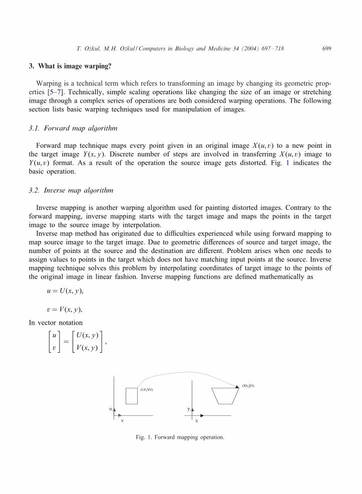
Forward map technique maps every point given in an original image X (u; v) to a new point inthe target image Y (x; y). Discrete number of steps are involved in transferring X (u; v) image toY (u; v) format. As a result of the operation the source image gets distorted. Fig. 1 indicates thebasic operation.
3.2. Inverse map algorithm
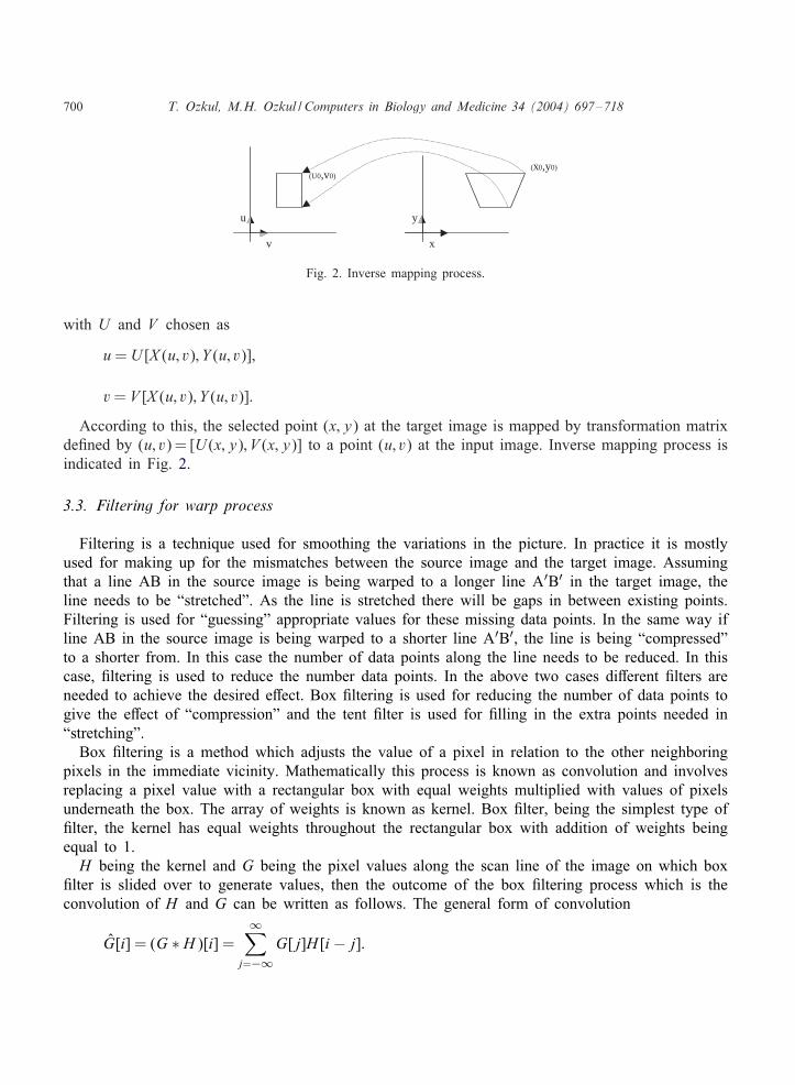
Inverse mapping is another warping algorithm used for painting distorted images. Contrary to theforward mapping, inverse mapping starts with the target image and maps the points in the targetimage to the source image by interpolation.
Inverse map method has originated due to diEculties experienced while using forward mapping tomap source image to the target image. Due to geometric di9erences of source and target image, thenumber of points at the source and the destination are di9erent. Problem arises when one needs toassign values to points in the target which does not have matching input points at the source. Inversemapping technique solves this problem by interpolating coordinates of target image to the points ofthe original image in linear fashion. Inverse mapping functions are de<ned mathematically as
u= U (x; y);
v= V (x; y);
In vector notation[u
v
]=
[U (x; y)
V (x; y)
];
v
u y
x
(U0,v0)(x0,y0)
Fig. 1. Forward mapping operation.
700 T. Ozkul, M.H. Ozkul / Computers in Biology and Medicine 34 (2004) 697–718
v
u y
x
(U0,v0)(x0,y0)
Fig. 2. Inverse mapping process.
with U and V chosen as
u= U [X (u; v); Y (u; v)];
v= V [X (u; v); Y (u; v)]:
According to this, the selected point (x; y) at the target image is mapped by transformation matrixde<ned by (u; v)= [U (x; y); V (x; y)] to a point (u; v) at the input image. Inverse mapping process isindicated in Fig. 2.
3.3. Filtering for warp process
Filtering is a technique used for smoothing the variations in the picture. In practice it is mostlyused for making up for the mismatches between the source image and the target image. Assumingthat a line AB in the source image is being warped to a longer line A′B′ in the target image, theline needs to be “stretched”. As the line is stretched there will be gaps in between existing points.Filtering is used for “guessing” appropriate values for these missing data points. In the same way ifline AB in the source image is being warped to a shorter line A′B′, the line is being “compressed”to a shorter from. In this case the number of data points along the line needs to be reduced. In thiscase, <ltering is used to reduce the number data points. In the above two cases di9erent <lters areneeded to achieve the desired e9ect. Box <ltering is used for reducing the number of data points togive the e9ect of “compression” and the tent <lter is used for <lling in the extra points needed in“stretching”.
Box <ltering is a method which adjusts the value of a pixel in relation to the other neighboringpixels in the immediate vicinity. Mathematically this process is known as convolution and involvesreplacing a pixel value with a rectangular box with equal weights multiplied with values of pixelsunderneath the box. The array of weights is known as kernel. Box <lter, being the simplest type of<lter, the kernel has equal weights throughout the rectangular box with addition of weights beingequal to 1.H being the kernel and G being the pixel values along the scan line of the image on which box
<lter is slided over to generate values, then the outcome of the box <ltering process which is theconvolution of H and G can be written as follows. The general form of convolution
G[i] = (G ∗ H)[i] =∞∑
j=−∞G[j]H [i − j]:
T. Ozkul, M.H. Ozkul / Computers in Biology and Medicine 34 (2004) 697–718 701
1
n n
box filter tent filter
4321
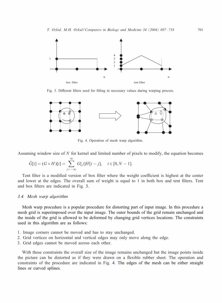
Fig. 3. Di9erent <lters used for <lling in necessary values during warping process.
Fig. 4. Operation of mesh warp algorithm.
Assuming window size of N for kernel and limited number of pixels to modify, the equation becomes
G[i] = (G ∗ H)[i] =∞∑
j=−∞G[j]H [i − j]; i∈ [0; N − 1]:
Tent <lter is a modi<ed version of box <lter where the weight coeEcient is highest at the centerand lower at the edges. The overall sum of weight is equal to 1 in both box and tent <lters. Tentand box <lters are indicated in Fig. 3.
3.4. Mesh warp algorithm
Mesh warp procedure is a popular procedure for distorting part of input image. In this procedure amesh grid is superimposed over the input image. The outer bounds of the grid remain unchanged andthe inside of the grid is allowed to be deformed by changing grid vertices locations. The constraintsused in this algorithm are as follows:
1. Image corners cannot be moved and has to stay unchanged.2. Grid vertices on horizontal and vertical edges may only move along the edge.3. Grid edges cannot be moved across each other.
With these constraints the overall size of the image remains unchanged but the image points insidethe picture can be distorted as if they were drawn on a =exible rubber sheet. The operation andconstraints of the procedure are indicated in Fig. 4. The edges of the mesh can be either straightlines or curved splines.
702 T. Ozkul, M.H. Ozkul / Computers in Biology and Medicine 34 (2004) 697–718
Y axis movement
X axis movement
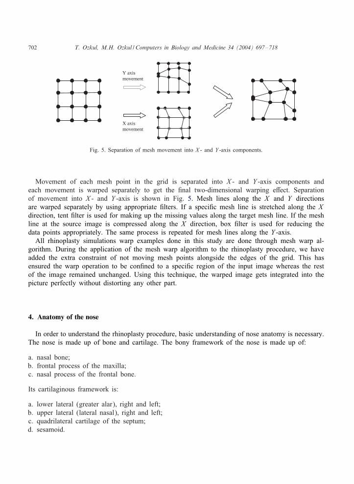
Fig. 5. Separation of mesh movement into X - and Y -axis components.
Movement of each mesh point in the grid is separated into X - and Y -axis components andeach movement is warped separately to get the <nal two-dimensional warping e9ect. Separationof movement into X - and Y -axis is shown in Fig. 5. Mesh lines along the X and Y directionsare warped separately by using appropriate <lters. If a speci<c mesh line is stretched along the Xdirection, tent <lter is used for making up the missing values along the target mesh line. If the meshline at the source image is compressed along the X direction, box <lter is used for reducing thedata points appropriately. The same process is repeated for mesh lines along the Y -axis.
All rhinoplasty simulations warp examples done in this study are done through mesh warp al-gorithm. During the application of the mesh warp algorithm to the rhinoplasty procedure, we haveadded the extra constraint of not moving mesh points alongside the edges of the grid. This hasensured the warp operation to be con<ned to a speci<c region of the input image whereas the restof the image remained unchanged. Using this technique, the warped image gets integrated into thepicture perfectly without distorting any other part.
4. Anatomy of the nose
In order to understand the rhinoplasty procedure, basic understanding of nose anatomy is necessary.The nose is made up of bone and cartilage. The bony framework of the nose is made up of:
a. nasal bone;b. frontal process of the maxilla;c. nasal process of the frontal bone.
Its cartilaginous framework is:
a. lower lateral (greater alar), right and left;b. upper lateral (lateral nasal), right and left;c. quadrilateral cartilage of the septum;d. sesamoid.
T. Ozkul, M.H. Ozkul / Computers in Biology and Medicine 34 (2004) 697–718 703
Lateral cartilage
Greater alar cartilage
Lateral crura
Nasal bone
Columella
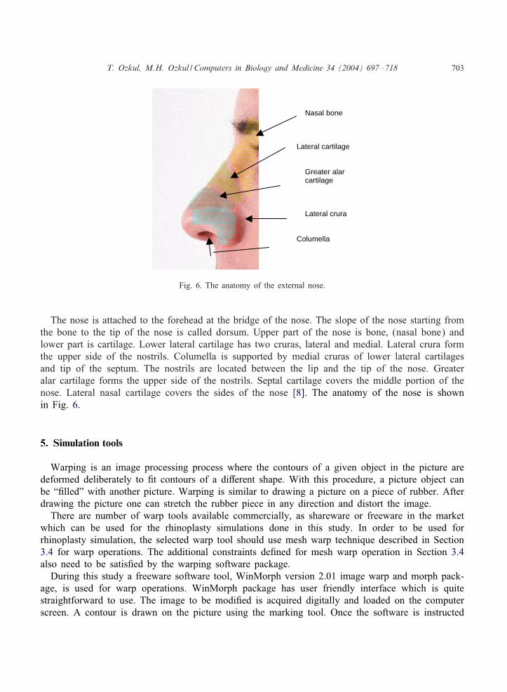
Fig. 6. The anatomy of the external nose.
The nose is attached to the forehead at the bridge of the nose. The slope of the nose starting fromthe bone to the tip of the nose is called dorsum. Upper part of the nose is bone, (nasal bone) andlower part is cartilage. Lower lateral cartilage has two cruras, lateral and medial. Lateral crura formthe upper side of the nostrils. Columella is supported by medial cruras of lower lateral cartilagesand tip of the septum. The nostrils are located between the lip and the tip of the nose. Greateralar cartilage forms the upper side of the nostrils. Septal cartilage covers the middle portion of thenose. Lateral nasal cartilage covers the sides of the nose [8]. The anatomy of the nose is shownin Fig. 6.
5. Simulation tools
Warping is an image processing process where the contours of a given object in the picture aredeformed deliberately to <t contours of a di9erent shape. With this procedure, a picture object canbe “<lled” with another picture. Warping is similar to drawing a picture on a piece of rubber. Afterdrawing the picture one can stretch the rubber piece in any direction and distort the image.
There are number of warp tools available commercially, as shareware or freeware in the marketwhich can be used for the rhinoplasty simulations done in this study. In order to be used forrhinoplasty simulation, the selected warp tool should use mesh warp technique described in Section3.4 for warp operations. The additional constraints de<ned for mesh warp operation in Section 3.4also need to be satis<ed by the warping software package.
During this study a freeware software tool, WinMorph version 2.01 image warp and morph pack-age, is used for warp operations. WinMorph package has user friendly interface which is quitestraightforward to use. The image to be modi<ed is acquired digitally and loaded on the computerscreen. A contour is drawn on the picture using the marking tool. Once the software is instructed
704 T. Ozkul, M.H. Ozkul / Computers in Biology and Medicine 34 (2004) 697–718
to work in warp mode, any change introduced to the contour is immediately worked out and theimage is distorted to the new form to accommodate the new contours.
6. The ideal nose
The simulation tool proposed in this study uses the image of the patient taken before the surgery.Our goal is to use realistic simulation tools which mimic the actual rhinoplastic surgical operationsto predict the <nal shape of the nose after the surgery. Since usually more than one procedure isused during the surgery and e9ect of one rhinoplastic procedure interferes with the e9ect of each,predicting the combined outcome of the rhinoplastic procedures is no easy task. It is the goal of thisstudy to estimate the variable parameters of surgery so that patient ends up with an ideal nose.
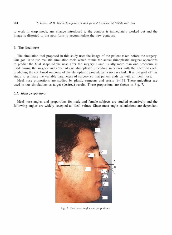
Ideal nose proportions are studied by plastic surgeons and artists [9–11]. These guidelines areused in our simulations as target (desired) results. These proportions are shown in Fig. 7.
6.1. Ideal proportions
Ideal nose angles and proportions for male and female subjects are studied extensively and thefollowing angles are widely accepted as ideal values. Since most angle calculations are dependant
Fig. 7. Ideal nose angles and proportions.
T. Ozkul, M.H. Ozkul / Computers in Biology and Medicine 34 (2004) 697–718 705
on the orientation of the face, a standard way of picturing the subjects is developed. According tothis, a virtual line extending from the most superior point of auditory canal to the most inferiorpoint of the interorbital rim is supposed to be parallel to the ground during photographing process.This line is indicated as line ED in Fig. 7 and called Frankfort plane. Before and after photographsof patients are always taken with Frankfort plane parallel to the ground.
The ideal angles and proportions are listed as follows:
• In ideal subjects, the nasofrontal angle (angle indicated by BAP in Fig. 7) should be between115◦ and 130◦. Within this range more obtuse is preferred for females and more acute preferredfor males.
• Nasal projection is measured as a ratio of IB line divided by line BS. This ration should be around0.55–0.60.
• Nasofacial angle is de<ned as SAB in Fig. 7 and ideally should be between 30◦ and 40◦.• Nasomental angle is described as ABF in Fig. 7 and ideally should be between 120◦ and 132◦.• Distance of lips to nasomental line which is indicated as BF in Fig. 7 should be 4 mm for upper
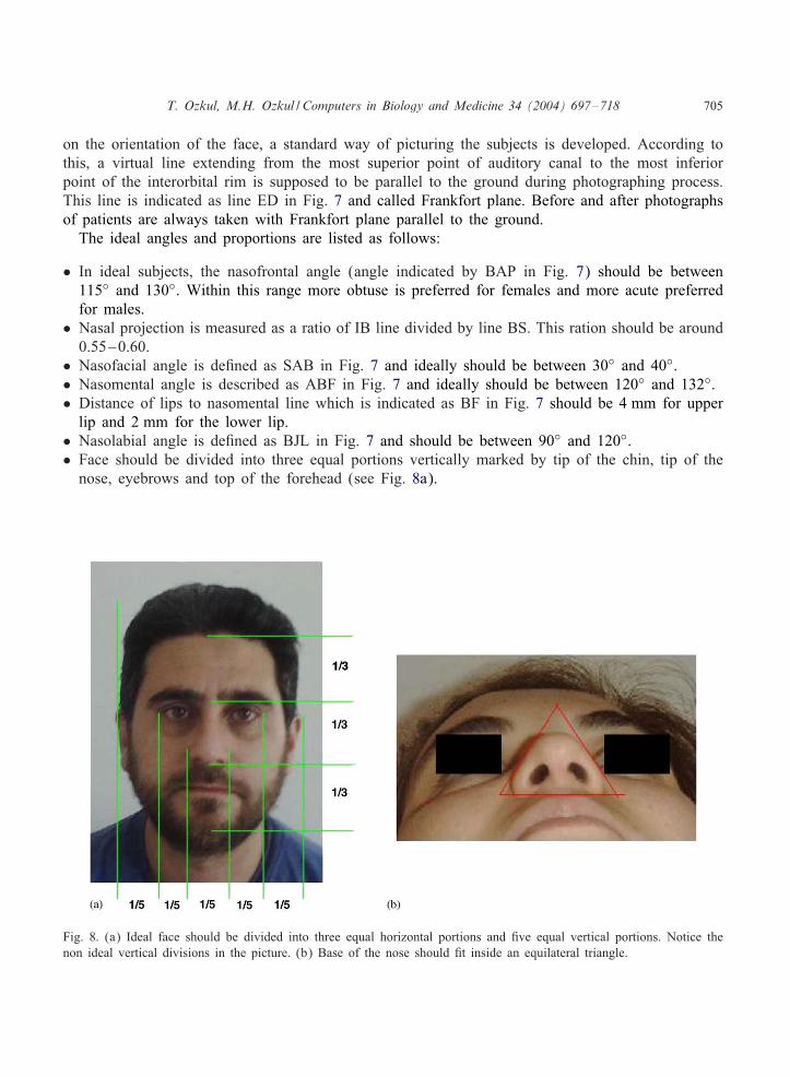
lip and 2 mm for the lower lip.• Nasolabial angle is de<ned as BJL in Fig. 7 and should be between 90◦ and 120◦.• Face should be divided into three equal portions vertically marked by tip of the chin, tip of the
nose, eyebrows and top of the forehead (see Fig. 8a).
Fig. 8. (a) Ideal face should be divided into three equal horizontal portions and <ve equal vertical portions. Notice thenon ideal vertical divisions in the picture. (b) Base of the nose should <t inside an equilateral triangle.
706 T. Ozkul, M.H. Ozkul / Computers in Biology and Medicine 34 (2004) 697–718
• Face should be divided into <ve equal vertical portions marked by the tip of the ears, outeredge of the eyes and outer edge of the nose (see Fig. 8a). Notice how the unequal vertical partsnoticeable in the picture.
• Base of the nose should <t inside an equilateral triangle as shown in Fig. 8b.
7. Major rhinoplasty procedures
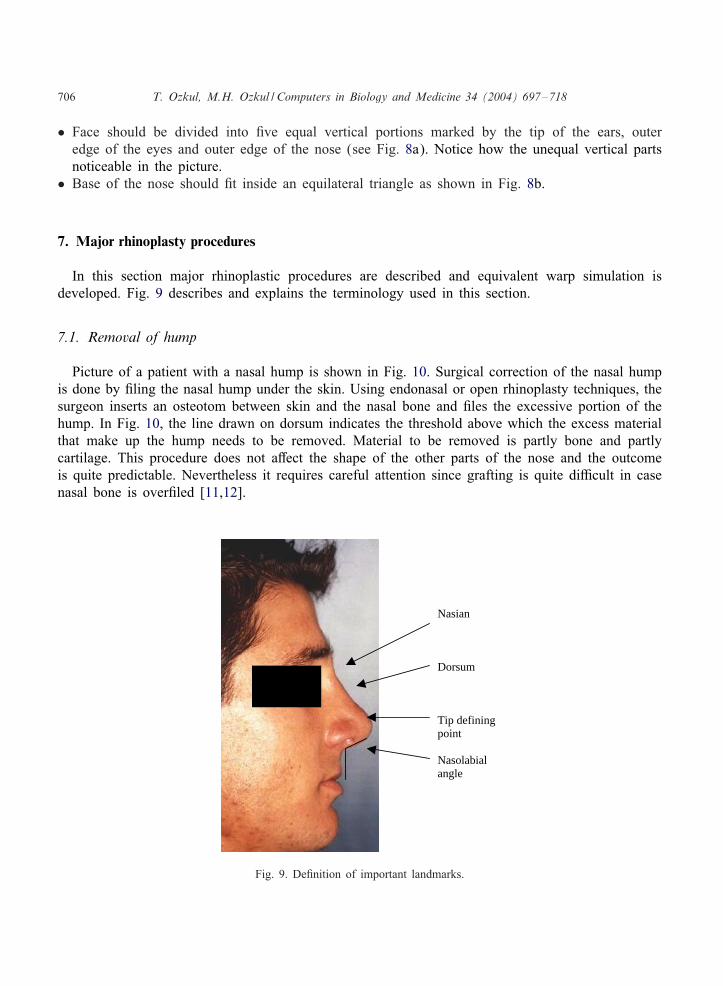
In this section major rhinoplastic procedures are described and equivalent warp simulation isdeveloped. Fig. 9 describes and explains the terminology used in this section.
7.1. Removal of hump
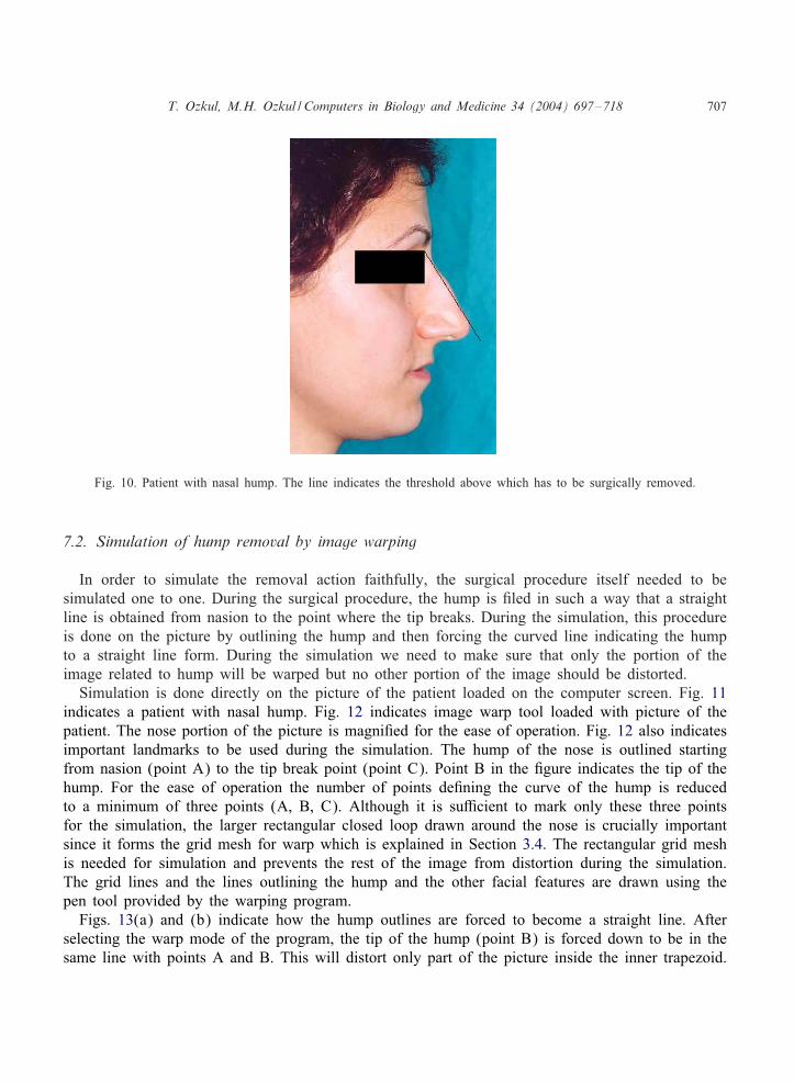
Picture of a patient with a nasal hump is shown in Fig. 10. Surgical correction of the nasal humpis done by <ling the nasal hump under the skin. Using endonasal or open rhinoplasty techniques, thesurgeon inserts an osteotom between skin and the nasal bone and <les the excessive portion of thehump. In Fig. 10, the line drawn on dorsum indicates the threshold above which the excess materialthat make up the hump needs to be removed. Material to be removed is partly bone and partlycartilage. This procedure does not a9ect the shape of the other parts of the nose and the outcomeis quite predictable. Nevertheless it requires careful attention since grafting is quite diEcult in casenasal bone is over<led [11,12].
Nasian
Dorsum
Tip defining point
Nasolabial angle
Fig. 9. De<nition of important landmarks.
T. Ozkul, M.H. Ozkul / Computers in Biology and Medicine 34 (2004) 697–718 707
Fig. 10. Patient with nasal hump. The line indicates the threshold above which has to be surgically removed.
7.2. Simulation of hump removal by image warping
In order to simulate the removal action faithfully, the surgical procedure itself needed to besimulated one to one. During the surgical procedure, the hump is <led in such a way that a straightline is obtained from nasion to the point where the tip breaks. During the simulation, this procedureis done on the picture by outlining the hump and then forcing the curved line indicating the humpto a straight line form. During the simulation we need to make sure that only the portion of theimage related to hump will be warped but no other portion of the image should be distorted.
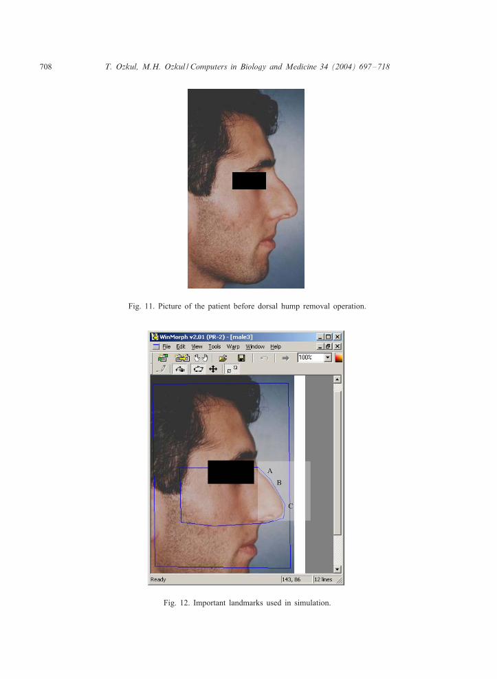
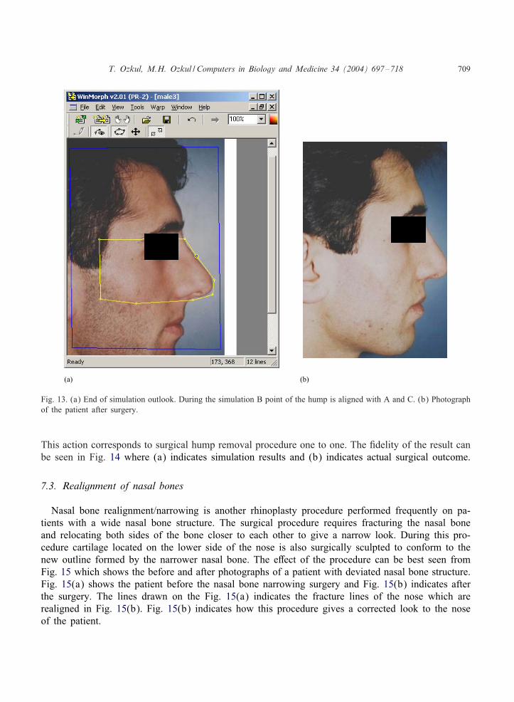
Simulation is done directly on the picture of the patient loaded on the computer screen. Fig. 11indicates a patient with nasal hump. Fig. 12 indicates image warp tool loaded with picture of thepatient. The nose portion of the picture is magni<ed for the ease of operation. Fig. 12 also indicatesimportant landmarks to be used during the simulation. The hump of the nose is outlined startingfrom nasion (point A) to the tip break point (point C). Point B in the <gure indicates the tip of thehump. For the ease of operation the number of points de<ning the curve of the hump is reducedto a minimum of three points (A, B, C). Although it is suEcient to mark only these three pointsfor the simulation, the larger rectangular closed loop drawn around the nose is crucially importantsince it forms the grid mesh for warp which is explained in Section 3.4. The rectangular grid meshis needed for simulation and prevents the rest of the image from distortion during the simulation.The grid lines and the lines outlining the hump and the other facial features are drawn using thepen tool provided by the warping program.
Figs. 13(a) and (b) indicate how the hump outlines are forced to become a straight line. Afterselecting the warp mode of the program, the tip of the hump (point B) is forced down to be in thesame line with points A and B. This will distort only part of the picture inside the inner trapezoid.
708 T. Ozkul, M.H. Ozkul / Computers in Biology and Medicine 34 (2004) 697–718
Fig. 11. Picture of the patient before dorsal hump removal operation.
Fig. 12. Important landmarks used in simulation.
T. Ozkul, M.H. Ozkul / Computers in Biology and Medicine 34 (2004) 697–718 709
(a) (b)
Fig. 13. (a) End of simulation outlook. During the simulation B point of the hump is aligned with A and C. (b) Photographof the patient after surgery.
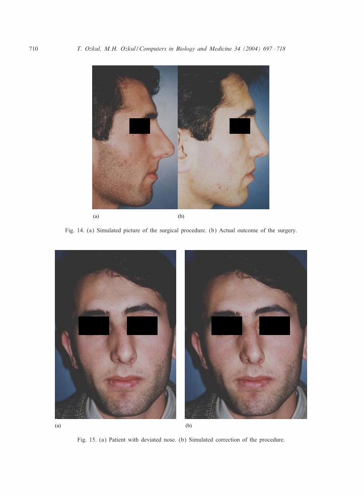
This action corresponds to surgical hump removal procedure one to one. The <delity of the result canbe seen in Fig. 14 where (a) indicates simulation results and (b) indicates actual surgical outcome.
7.3. Realignment of nasal bones
Nasal bone realignment/narrowing is another rhinoplasty procedure performed frequently on pa-tients with a wide nasal bone structure. The surgical procedure requires fracturing the nasal boneand relocating both sides of the bone closer to each other to give a narrow look. During this pro-cedure cartilage located on the lower side of the nose is also surgically sculpted to conform to thenew outline formed by the narrower nasal bone. The e9ect of the procedure can be best seen fromFig. 15 which shows the before and after photographs of a patient with deviated nasal bone structure.Fig. 15(a) shows the patient before the nasal bone narrowing surgery and Fig. 15(b) indicates afterthe surgery. The lines drawn on the Fig. 15(a) indicates the fracture lines of the nose which arerealigned in Fig. 15(b). Fig. 15(b) indicates how this procedure gives a corrected look to the noseof the patient.
710 T. Ozkul, M.H. Ozkul / Computers in Biology and Medicine 34 (2004) 697–718
(a) (b)
Fig. 14. (a) Simulated picture of the surgical procedure. (b) Actual outcome of the surgery.
(a) (b)
Fig. 15. (a) Patient with deviated nose. (b) Simulated correction of the procedure.
T. Ozkul, M.H. Ozkul / Computers in Biology and Medicine 34 (2004) 697–718 711
(a) (b)
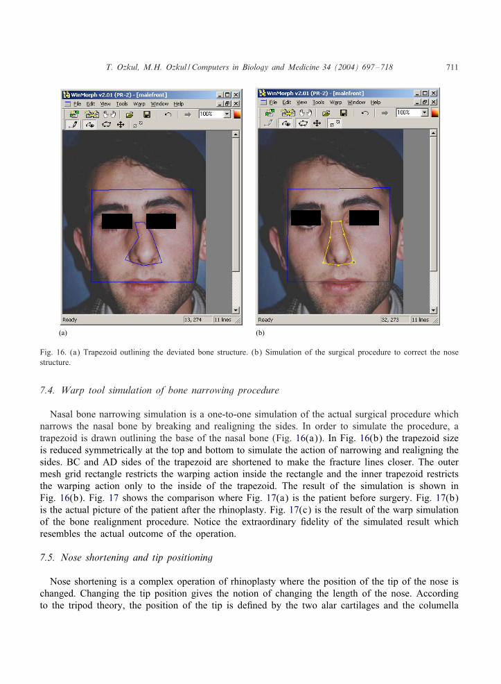
Fig. 16. (a) Trapezoid outlining the deviated bone structure. (b) Simulation of the surgical procedure to correct the nosestructure.
7.4. Warp tool simulation of bone narrowing procedure
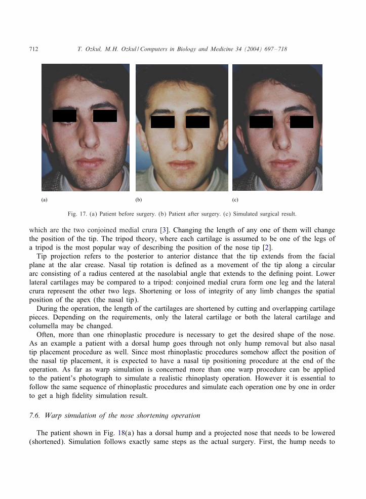
Nasal bone narrowing simulation is a one-to-one simulation of the actual surgical procedure whichnarrows the nasal bone by breaking and realigning the sides. In order to simulate the procedure, atrapezoid is drawn outlining the base of the nasal bone (Fig. 16(a)). In Fig. 16(b) the trapezoid sizeis reduced symmetrically at the top and bottom to simulate the action of narrowing and realigning thesides. BC and AD sides of the trapezoid are shortened to make the fracture lines closer. The outermesh grid rectangle restricts the warping action inside the rectangle and the inner trapezoid restrictsthe warping action only to the inside of the trapezoid. The result of the simulation is shown inFig. 16(b). Fig. 17 shows the comparison where Fig. 17(a) is the patient before surgery. Fig. 17(b)is the actual picture of the patient after the rhinoplasty. Fig. 17(c) is the result of the warp simulationof the bone realignment procedure. Notice the extraordinary <delity of the simulated result whichresembles the actual outcome of the operation.
7.5. Nose shortening and tip positioning
Nose shortening is a complex operation of rhinoplasty where the position of the tip of the nose ischanged. Changing the tip position gives the notion of changing the length of the nose. Accordingto the tripod theory, the position of the tip is de<ned by the two alar cartilages and the columella
712 T. Ozkul, M.H. Ozkul / Computers in Biology and Medicine 34 (2004) 697–718
(a) (b) (c)
Fig. 17. (a) Patient before surgery. (b) Patient after surgery. (c) Simulated surgical result.
which are the two conjoined medial crura [3]. Changing the length of any one of them will changethe position of the tip. The tripod theory, where each cartilage is assumed to be one of the legs ofa tripod is the most popular way of describing the position of the nose tip [2].
Tip projection refers to the posterior to anterior distance that the tip extends from the facialplane at the alar crease. Nasal tip rotation is de<ned as a movement of the tip along a circulararc consisting of a radius centered at the nasolabial angle that extends to the de<ning point. Lowerlateral cartilages may be compared to a tripod: conjoined medial crura form one leg and the lateralcrura represent the other two legs. Shortening or loss of integrity of any limb changes the spatialposition of the apex (the nasal tip).
During the operation, the length of the cartilages are shortened by cutting and overlapping cartilagepieces. Depending on the requirements, only the lateral cartilage or both the lateral cartilage andcolumella may be changed.
Often, more than one rhinoplastic procedure is necessary to get the desired shape of the nose.As an example a patient with a dorsal hump goes through not only hump removal but also nasaltip placement procedure as well. Since most rhinoplastic procedures somehow a9ect the position ofthe nasal tip placement, it is expected to have a nasal tip positioning procedure at the end of theoperation. As far as warp simulation is concerned more than one warp procedure can be appliedto the patient’s photograph to simulate a realistic rhinoplasty operation. However it is essential tofollow the same sequence of rhinoplastic procedures and simulate each operation one by one in orderto get a high <delity simulation result.
7.6. Warp simulation of the nose shortening operation
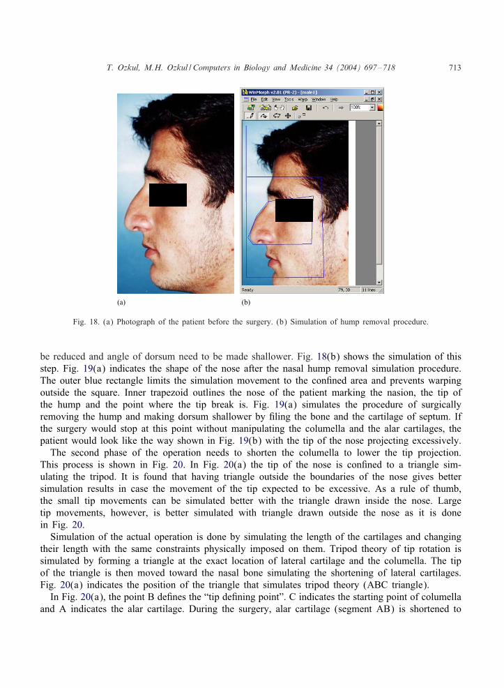
The patient shown in Fig. 18(a) has a dorsal hump and a projected nose that needs to be lowered(shortened). Simulation follows exactly same steps as the actual surgery. First, the hump needs to
T. Ozkul, M.H. Ozkul / Computers in Biology and Medicine 34 (2004) 697–718 713
(a) (b)
Fig. 18. (a) Photograph of the patient before the surgery. (b) Simulation of hump removal procedure.
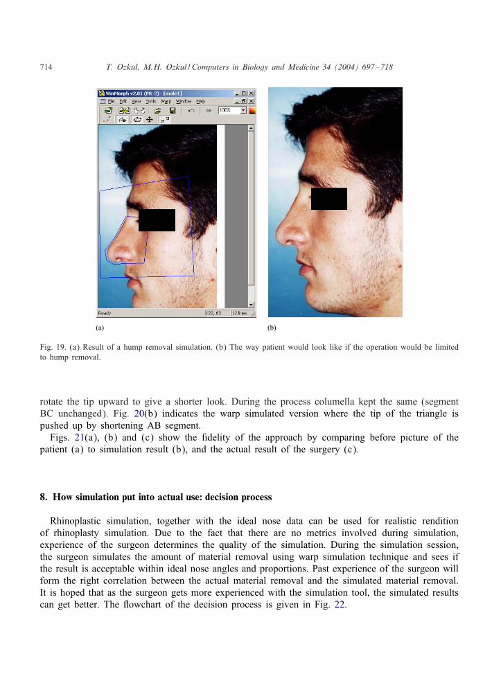
be reduced and angle of dorsum need to be made shallower. Fig. 18(b) shows the simulation of thisstep. Fig. 19(a) indicates the shape of the nose after the nasal hump removal simulation procedure.The outer blue rectangle limits the simulation movement to the con<ned area and prevents warpingoutside the square. Inner trapezoid outlines the nose of the patient marking the nasion, the tip ofthe hump and the point where the tip break is. Fig. 19(a) simulates the procedure of surgicallyremoving the hump and making dorsum shallower by <ling the bone and the cartilage of septum. Ifthe surgery would stop at this point without manipulating the columella and the alar cartilages, thepatient would look like the way shown in Fig. 19(b) with the tip of the nose projecting excessively.
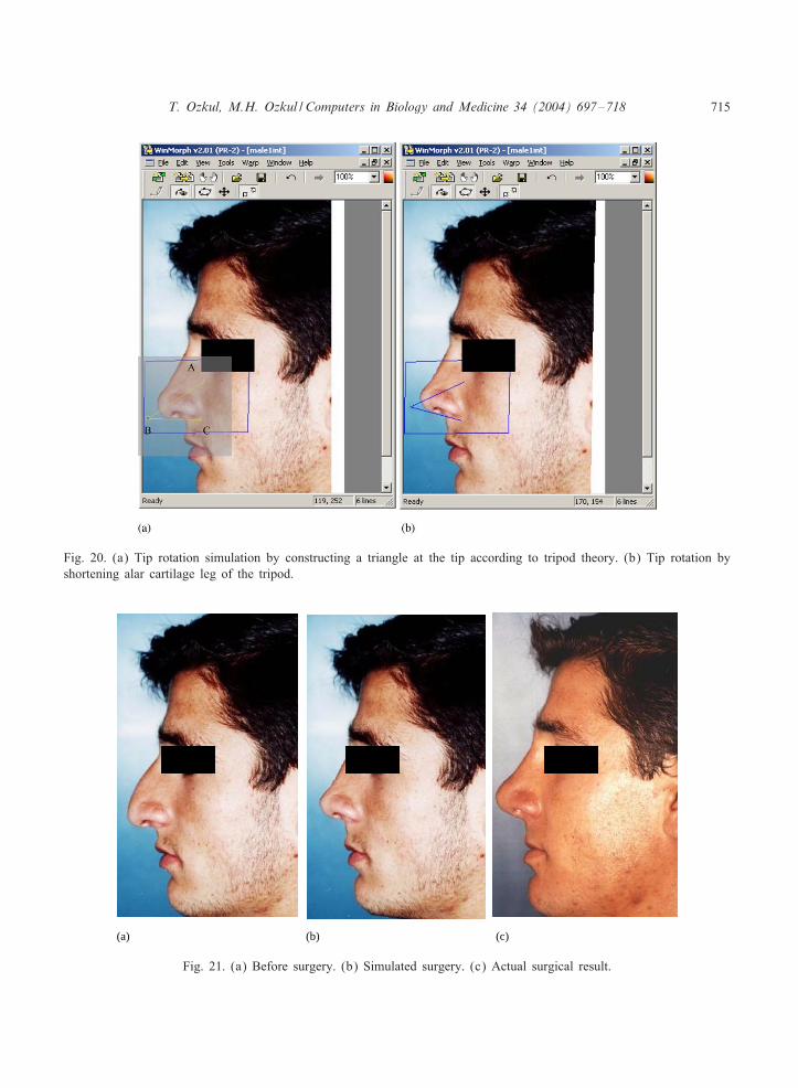
The second phase of the operation needs to shorten the columella to lower the tip projection.This process is shown in Fig. 20. In Fig. 20(a) the tip of the nose is con<ned to a triangle sim-ulating the tripod. It is found that having triangle outside the boundaries of the nose gives bettersimulation results in case the movement of the tip expected to be excessive. As a rule of thumb,the small tip movements can be simulated better with the triangle drawn inside the nose. Largetip movements, however, is better simulated with triangle drawn outside the nose as it is donein Fig. 20.
Simulation of the actual operation is done by simulating the length of the cartilages and changingtheir length with the same constraints physically imposed on them. Tripod theory of tip rotation issimulated by forming a triangle at the exact location of lateral cartilage and the columella. The tipof the triangle is then moved toward the nasal bone simulating the shortening of lateral cartilages.Fig. 20(a) indicates the position of the triangle that simulates tripod theory (ABC triangle).In Fig. 20(a), the point B de<nes the “tip de<ning point”. C indicates the starting point of columella
and A indicates the alar cartilage. During the surgery, alar cartilage (segment AB) is shortened to
714 T. Ozkul, M.H. Ozkul / Computers in Biology and Medicine 34 (2004) 697–718
(a) (b)
Fig. 19. (a) Result of a hump removal simulation. (b) The way patient would look like if the operation would be limitedto hump removal.
rotate the tip upward to give a shorter look. During the process columella kept the same (segmentBC unchanged). Fig. 20(b) indicates the warp simulated version where the tip of the triangle ispushed up by shortening AB segment.
Figs. 21(a), (b) and (c) show the <delity of the approach by comparing before picture of thepatient (a) to simulation result (b), and the actual result of the surgery (c).
8. How simulation put into actual use: decision process
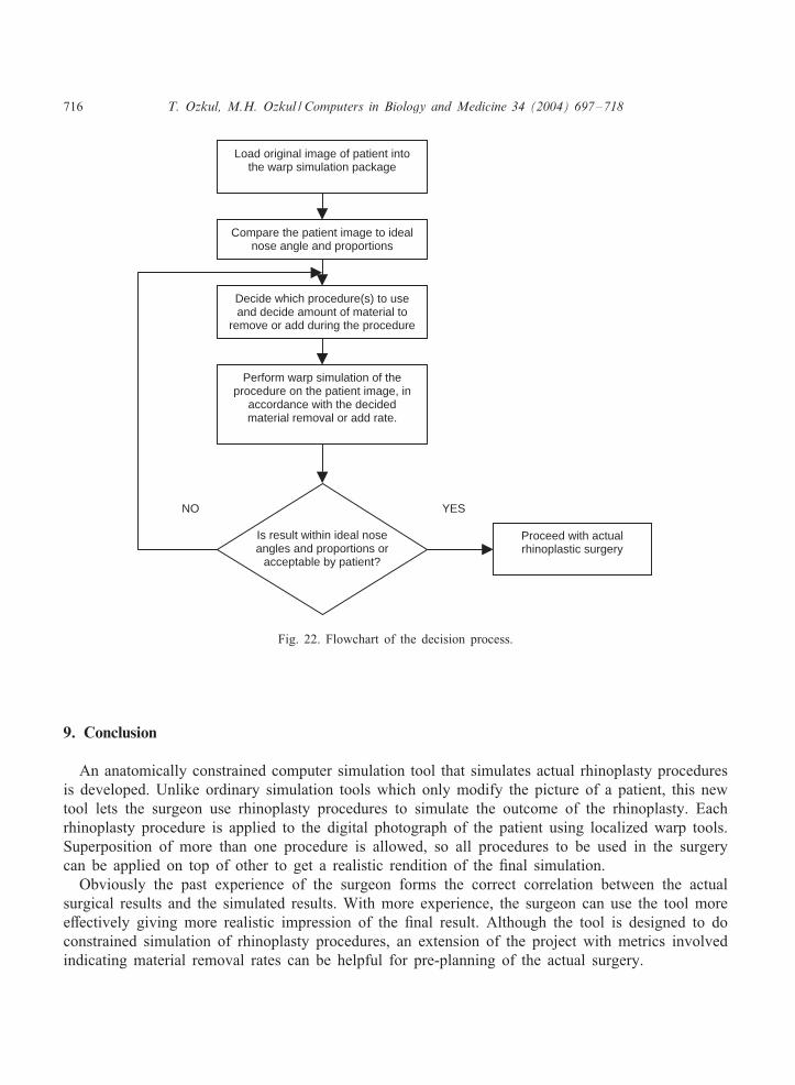
Rhinoplastic simulation, together with the ideal nose data can be used for realistic renditionof rhinoplasty simulation. Due to the fact that there are no metrics involved during simulation,experience of the surgeon determines the quality of the simulation. During the simulation session,the surgeon simulates the amount of material removal using warp simulation technique and sees ifthe result is acceptable within ideal nose angles and proportions. Past experience of the surgeon willform the right correlation between the actual material removal and the simulated material removal.It is hoped that as the surgeon gets more experienced with the simulation tool, the simulated resultscan get better. The =owchart of the decision process is given in Fig. 22.
T. Ozkul, M.H. Ozkul / Computers in Biology and Medicine 34 (2004) 697–718 715
Fig. 20. (a) Tip rotation simulation by constructing a triangle at the tip according to tripod theory. (b) Tip rotation byshortening alar cartilage leg of the tripod.
(a) (b) (c)
Fig. 21. (a) Before surgery. (b) Simulated surgery. (c) Actual surgical result.
716 T. Ozkul, M.H. Ozkul / Computers in Biology and Medicine 34 (2004) 697–718
Load original image of patient into the warp simulation package
Compare the patient image to ideal nose angle and proportions
Decide which procedure(s) to use and decide amount of material to
remove or add during the procedure
Perform warp simulation of the procedure on the patient image, in
accordance with the decided material removal or add rate.
Is result within ideal nose angles and proportions or
acceptable by patient?
YES
Proceed with actual rhinoplastic surgery
NO
Fig. 22. Flowchart of the decision process.
9. Conclusion
An anatomically constrained computer simulation tool that simulates actual rhinoplasty proceduresis developed. Unlike ordinary simulation tools which only modify the picture of a patient, this newtool lets the surgeon use rhinoplasty procedures to simulate the outcome of the rhinoplasty. Eachrhinoplasty procedure is applied to the digital photograph of the patient using localized warp tools.Superposition of more than one procedure is allowed, so all procedures to be used in the surgerycan be applied on top of other to get a realistic rendition of the <nal simulation.
Obviously the past experience of the surgeon forms the correct correlation between the actualsurgical results and the simulated results. With more experience, the surgeon can use the tool moree9ectively giving more realistic impression of the <nal result. Although the tool is designed to doconstrained simulation of rhinoplasty procedures, an extension of the project with metrics involvedindicating material removal rates can be helpful for pre-planning of the actual surgery.
T. Ozkul, M.H. Ozkul / Computers in Biology and Medicine 34 (2004) 697–718 717
10. Summary
In this paper and image warp tool simulation procedure is developed for simulating the a9ect ofrhinoplastic procedures. The image simulation is done by warping the image of the patient takenbefore the surgery and applying the equivalent rhinoplastic technique to the digital photograph of thepatient. No photo retouching or image alterations performed on the image other than the simulationof the surgical procedure. With this pretext, it is shown that image warping tools can be usede9ectively to simulate the outcome of rhinoplasty.
Ideal nasal proportions and angles are used as guidelines during the simulation. Before surgerypicture of the patient is modi<ed through various rhinoplastic procedure simulations to get theangles and proportions to a desirable range. The process can be iterated over and over again untilthe desirable shape is achieved. The tool used is a localized warping tool which modi<es only theparts involved. In case more than one procedure is to be used, the e9ect of the procedures can besuperimposed to get the desired e9ect.
The accuracy of the simulation is mostly due to the fact that warp tools are used to mimic theactual rhinoplastic procedure one to one. Rather than playing with the image to get the desired look,we have used the warp tool to simulate the e9ect of the surgical procedure. It is shown that a varietyof rhinoplasty procedures can be accurately mimicked this way. It is also shown that combinationprocedures can also be simulated by simulating each procedure in succession to the same patientjust like the way it is done in actual rhinoplasty.
References
[1] J.R. Anderson, The dynamics of rhinoplasty, Proceedings of the Ninth International Congress of Otorhinolaryngology,Excerpta Medica, Vol. 206, 1969.
[2] J.R. Anderson, New approach to rhinoplasty, A <ve-year reappraisal, Arch Otolaryngol. 93 (3) (1971) 284–291.[3] R.K. Daniel, The nasal tip: anatomy and aesthetics, Plast. Reconstr. Surg. 89 (2) (1992) 216–224.[4] M. Ercolani, B. Baldaro, N. Rossi, E. Trombini, Short term outcome of rhinoplasty for medical or cosmetic indication,
J. Phycosom. Res. 47 (3) (1999) 277–281.[5] G. Wolberg, Digital Image Warping, Wiley, IEEE Press, New York, 1990.[6] D.H. House, The Digital Image, Class notes, 1999, http://www-viz.tamu.edu/courses/viza654/99fall/.[7] J. Foley, A. Van Dam, S. Feiner, J. Hughes, Computer Graphics Principles and Practice, Addison-Wesley, Reading,
MA, 1990.[8] R.K. Daniel, A. Letourneau, Rhinoplasty: nasal anatomy, Ann. Plast. Surg. 20 (1) (1988) 5–13.[9] S. Cordes, Re<nement of the Nasal Tip, Grand Rounds Presentation, UTMB, Department of Otolaryngology, February
16, 2000, http://www.utmb.edu/otoref/Grnds/Nasal-Tip-200002/Nasal-Tip-200002.htm.[10] D.G. Becker, The ideal nose, 2002, http://www.revisionrhinoplasty.com/ideal.html.[11] Ideal nasal proportions, Yale University School of Medicine, Core curriculum, 2002, http://yalesurgery.
med.yale.edu/surgery/sections/plastics/Core%20Curriculum%20Pages/Rhinoplasty%20Page/RhinoAns1.html.[12] S.M. Denenberg, Case studies, Rhinoplasty tutorial, www.facialsurgery.com, 2002.
Tarik Ozkul has graduated from Bogazici University in 1981 with BS in Electrical Engineering. He has received his MSand PhD in Electrical and Computer Engineering in the year 1984 and 1988 respectively. After working for industry forseveral years as chief knowledge engineer and senior design engineer, he has joined the Computer Engineering Department
718 T. Ozkul, M.H. Ozkul / Computers in Biology and Medicine 34 (2004) 697–718
of American University of Sharjah. He is specialized in Data Acquisition area and published a book on the subject. Hisresearch interests include computer applications, alternative computing methods and medical application of computers.
M. Haluk Ozkul has graduated from Hacettepe Medical School, Ankara, Turkey in 1982 with <rst rank. After serving2 years of compulsory state medical service, he has started his ENT residency in Ankara State Educational hospitaland became Otolaryngology specialist in 1987. After graduation he has joined Vakif Gureba Hospital/Istanbul, as chiefassistant. In 1993, he worked as a supervisor in Temporal bone Dissection laboratory of Massachusetts Eye and EarIn<rmary. He became an Associate Professor of Otolaryngology in the year 2000. In the beginning of year 2001, he wasappointed as the Chief of Otolaryngology Clinic 1 in Vakif Gureba Hospital, Istanbul. He has published more than 70papers and is very active in participating regional and international workshops.
Related Documents