Computer Networks Network layer (Part 3)

Computer Networks Network layer (Part 3). Network layer (part 3) Last two classes Network layer functionality IP network layer implementation –IP security,
Dec 22, 2015
Welcome message from author
This document is posted to help you gain knowledge. Please leave a comment to let me know what you think about it! Share it to your friends and learn new things together.
Transcript
Computer Networks
Network layer (Part 3)
Network layer (part 3)
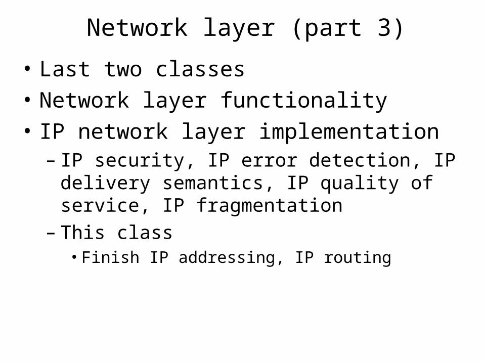
• Last two classes
• Network layer functionality
• IP network layer implementation– IP security, IP error detection, IP delivery semantics,
IP quality of service, IP fragmentation– This class
• Finish IP addressing, IP routing
NL: IP addressing and NAT
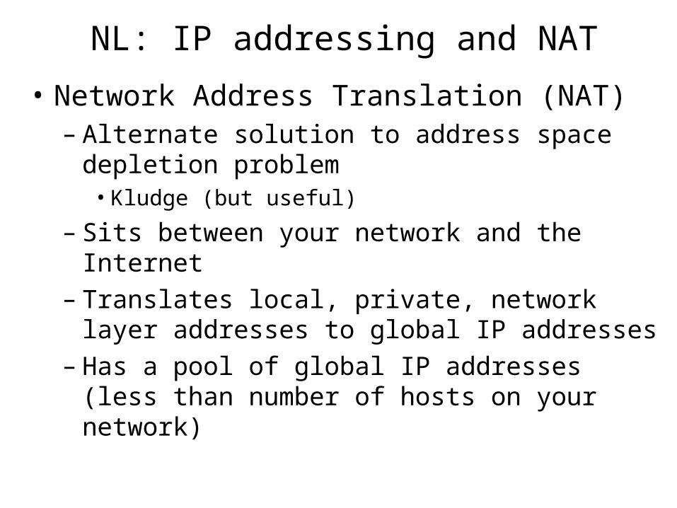
• Network Address Translation (NAT) – Alternate solution to address space depletion problem
• Kludge (but useful)
– Sits between your network and the Internet– Translates local, private, network layer addresses to
global IP addresses– Has a pool of global IP addresses (less than number of
hosts on your network)
NL: NAT Illustration
Global Internet
PrivateNetwork
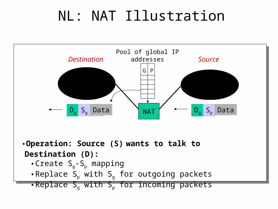
Pool of global IP addresses
•Operation: Source (S) wants to talk to Destination (D):• Create Sg-Sp mapping• Replace Sp with Sg for outgoing packets• Replace Sg with Sp for incoming packets
PG
Dg Sp DataNAT
Destination Source
Dg Sg Data
NL: Problems with NAT
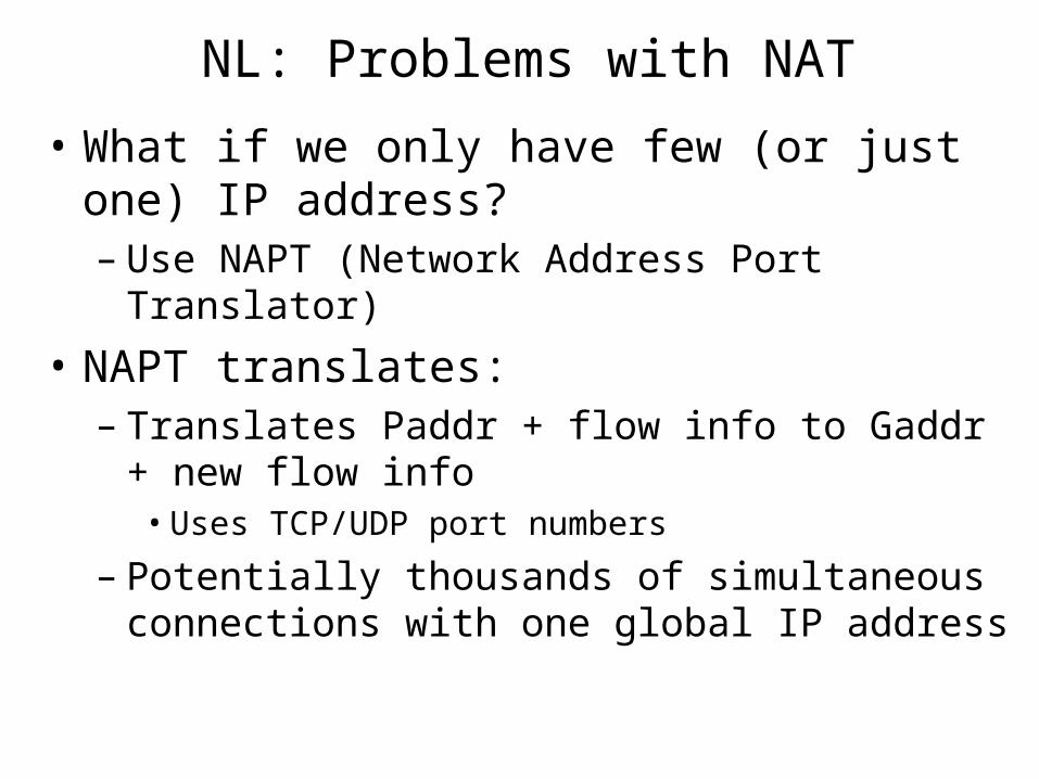
• What if we only have few (or just one) IP address? – Use NAPT (Network Address Port Translator)
• NAPT translates:– Translates Paddr + flow info to Gaddr + new flow
info• Uses TCP/UDP port numbers
– Potentially thousands of simultaneous connections with one global IP address
NL: Problems with NAT
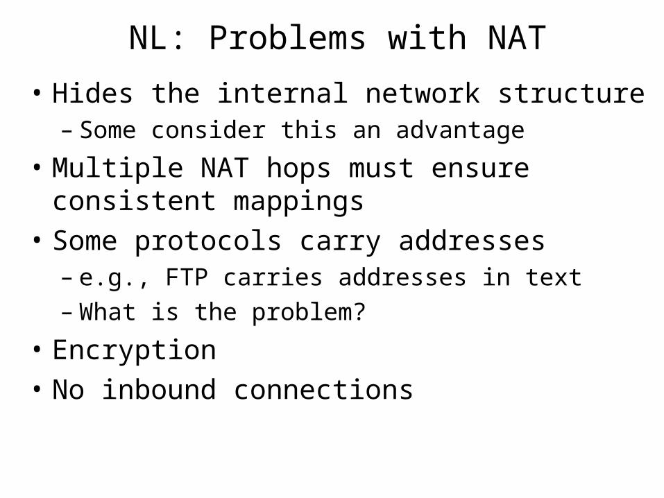
• Hides the internal network structure– Some consider this an advantage
• Multiple NAT hops must ensure consistent mappings
• Some protocols carry addresses– e.g., FTP carries addresses in text– What is the problem?
• Encryption
• No inbound connections
NL: IP routing
• Who provides the functionality?
• Internet area hierarchy
• IP route lookups– Original route lookup– CIDR address aggregation
• Specific IP routing protocols– Intra-AS routing– Inter-AS routing
NL: Who handles IP routing functions?
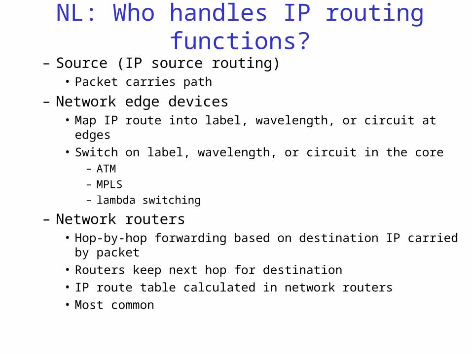
– Source (IP source routing)• Packet carries path
– Network edge devices• Map IP route into label, wavelength, or circuit at edges
• Switch on label, wavelength, or circuit in the core– ATM
– MPLS
– lambda switching
– Network routers• Hop-by-hop forwarding based on destination IP carried by packet
• Routers keep next hop for destination
• IP route table calculated in network routers
• Most common
NL: Source Routing
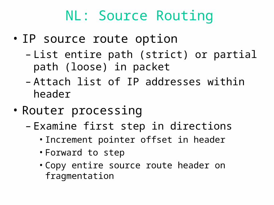
• IP source route option– List entire path (strict) or partial path (loose) in packet– Attach list of IP addresses within header
• Router processing– Examine first step in directions
• Increment pointer offset in header
• Forward to step
• Copy entire source route header on fragmentation
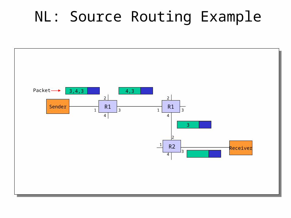
NL: Source Routing Example
Receiver
Packet 3,4,3
Sender
2
34
1
2
34
1
2
34
1
R1
R2
R1
4,3
3
NL: Source Routing
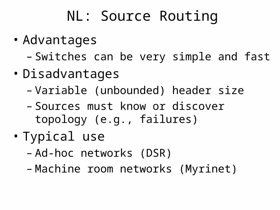
• Advantages– Switches can be very simple and fast
• Disadvantages– Variable (unbounded) header size– Sources must know or discover topology (e.g.,
failures)
• Typical use– Ad-hoc networks (DSR)– Machine room networks (Myrinet)
NL: Network edge devices
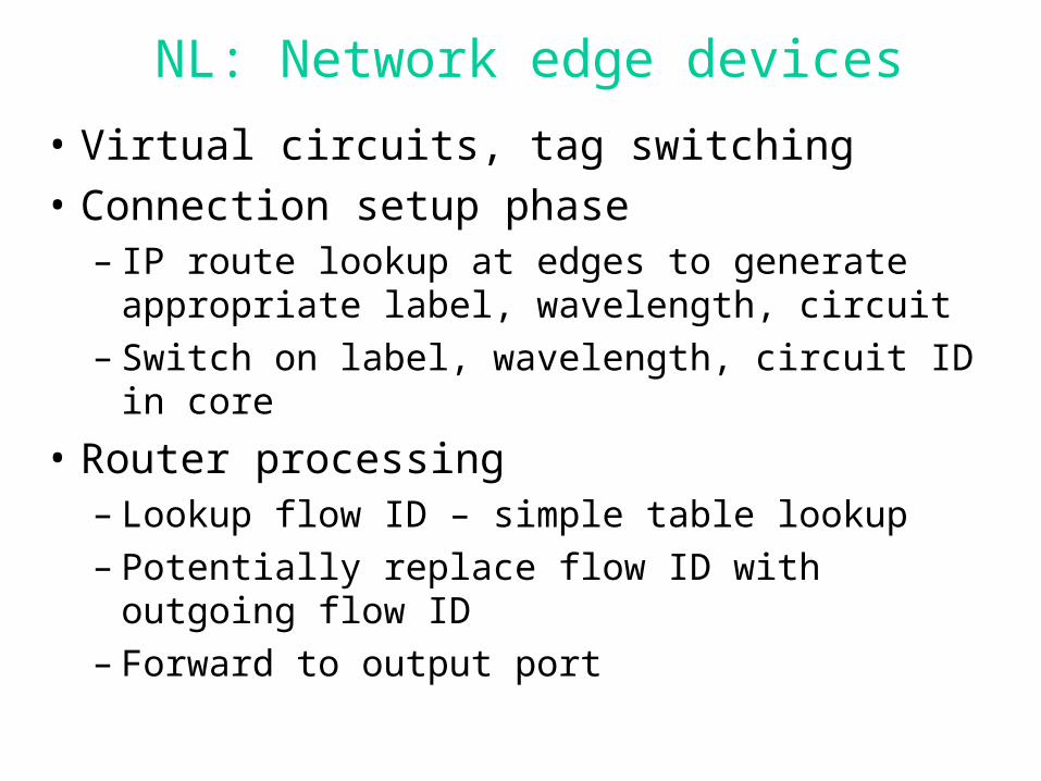
• Virtual circuits, tag switching
• Connection setup phase– IP route lookup at edges to generate appropriate label,
wavelength, circuit– Switch on label, wavelength, circuit ID in core
• Router processing– Lookup flow ID – simple table lookup– Potentially replace flow ID with outgoing flow ID– Forward to output port
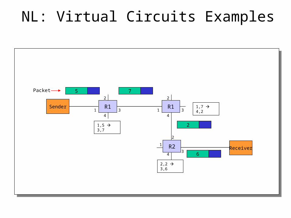
NL: Virtual Circuits Examples
Receiver
Packet
1,5 3,7
Sender
2
34
11,7 4,2
2
34
1
2
34
1
2,2 3,6
R1
R2
R1
5 7
2
6
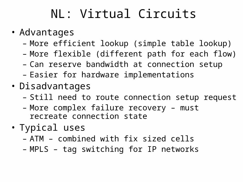
NL: Virtual Circuits
• Advantages– More efficient lookup (simple table lookup)– More flexible (different path for each flow)– Can reserve bandwidth at connection setup– Easier for hardware implementations
• Disadvantages– Still need to route connection setup request– More complex failure recovery – must recreate connection
state
• Typical uses– ATM – combined with fix sized cells– MPLS – tag switching for IP networks
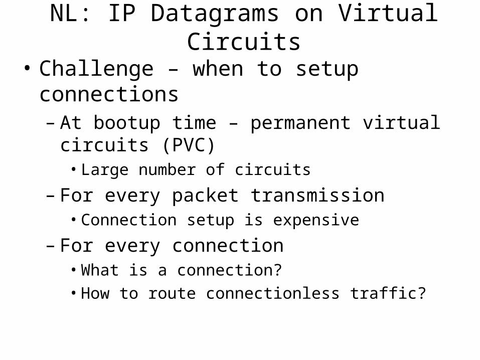
NL: IP Datagrams on Virtual Circuits
• Challenge – when to setup connections– At bootup time – permanent virtual circuits (PVC)
• Large number of circuits
– For every packet transmission• Connection setup is expensive
– For every connection• What is a connection?
• How to route connectionless traffic?
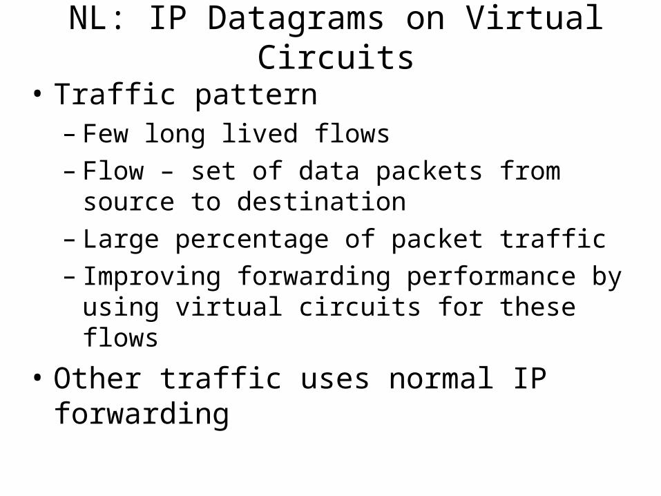
NL: IP Datagrams on Virtual Circuits
• Traffic pattern– Few long lived flows– Flow – set of data packets from source to destination– Large percentage of packet traffic– Improving forwarding performance by using virtual
circuits for these flows
• Other traffic uses normal IP forwarding
NL: Network routers (Global IP addresses)
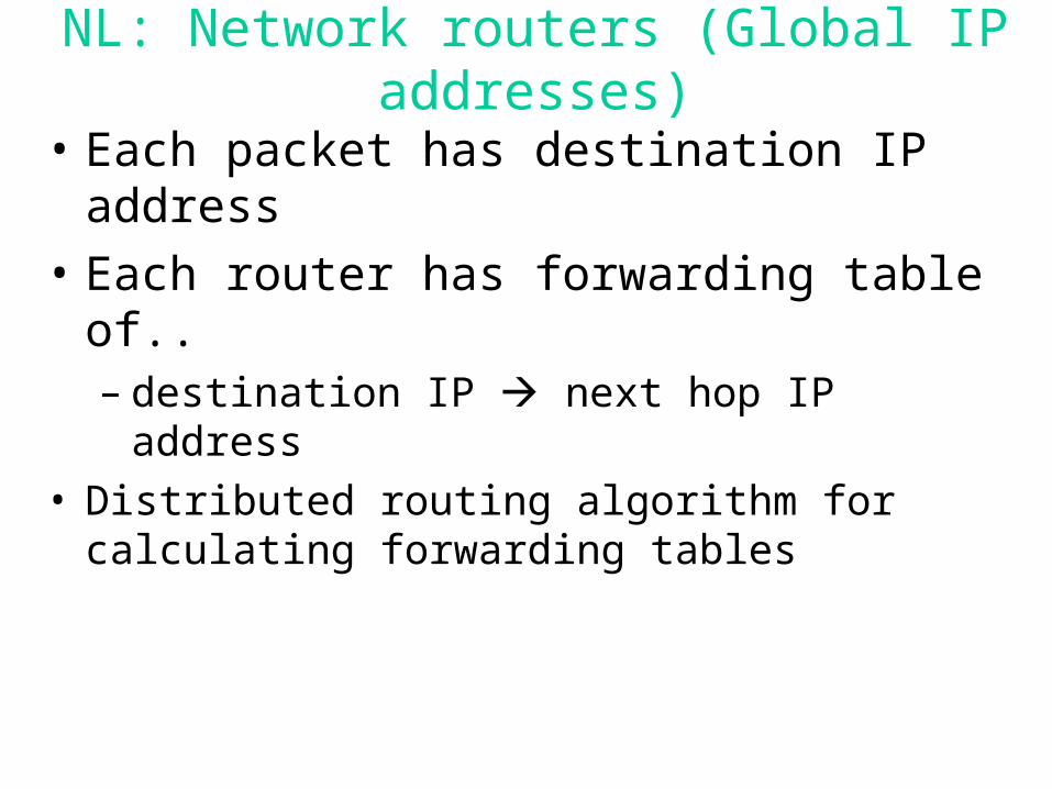
• Each packet has destination IP address
• Each router has forwarding table of..– destination IP next hop IP address
• Distributed routing algorithm for calculating forwarding tables

NL: Global Address Example
Receiver
Packet R
Sender
2
34
1
2
34
1
2
34
1
R1
R2
R1
R
RR 3
R 4
R 3
R
NL: Router Table Size
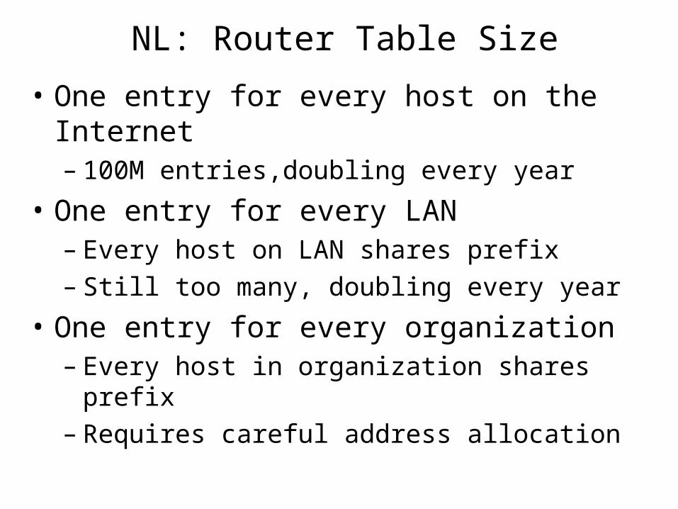
• One entry for every host on the Internet– 100M entries,doubling every year
• One entry for every LAN– Every host on LAN shares prefix– Still too many, doubling every year
• One entry for every organization– Every host in organization shares prefix– Requires careful address allocation
NL: Global Addresses
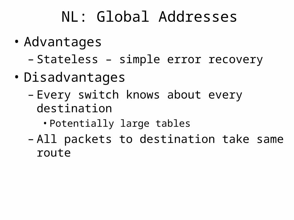
• Advantages– Stateless – simple error recovery
• Disadvantages– Every switch knows about every destination
• Potentially large tables
– All packets to destination take same route
NL: Comparison
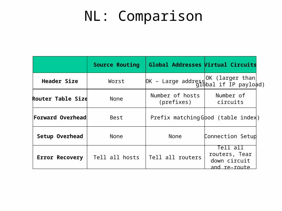
Source Routing Global Addresses
Header Size Worst OK – Large address
Router Table Size NoneNumber of hosts
(prefixes)
Forward Overhead Best Prefix matching
Virtual Circuits
OK (larger thanglobal if IP payload)
Number of circuits
Good (table index)
Setup Overhead None None
Error Recovery Tell all hosts Tell all routers
Connection Setup
Tell all routers, Tear down circuit
and re-route
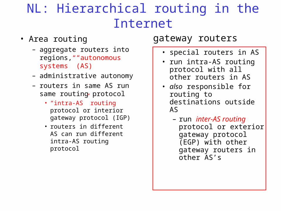
NL: Hierarchical routing in the Internet
• Area routing– aggregate routers into
regions, “autonomous systems” (AS)
– administrative autonomy
– routers in same AS run same routing protocol
• “intra-AS” routing protocol or interior gateway protocol (IGP)
• routers in different AS can run different intra-AS routing protocol
• special routers in AS• run intra-AS routing
protocol with all other routers in AS
• also responsible for routing to destinations outside AS– run inter-AS routing
protocol or exterior gateway protocol (EGP) with other gateway routers in other AS’s
gateway routers
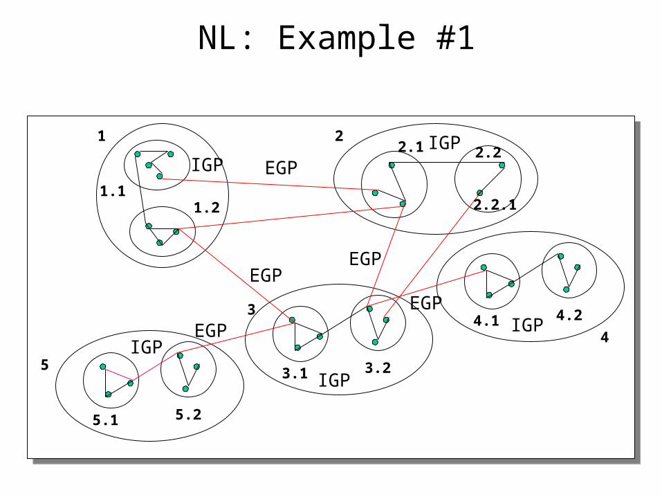
NL: Example #1
1 2
3
1.11.2
2.1 2.2
3.1 3.2
2.2.1
44.1 4.2
5
5.1 5.2
EGP
IGP
EGPEGP
IGP
IGP
IGPIGP
EGP
EGP
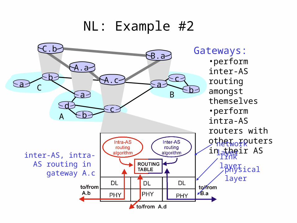
NL: Example #2
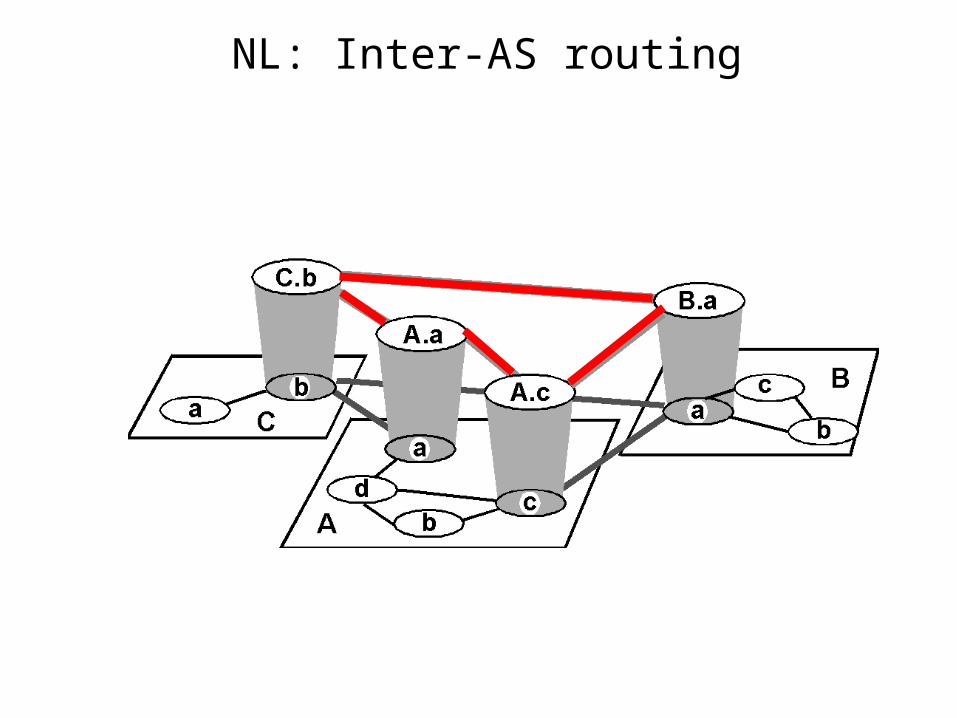
Gateways:•perform inter-AS routing amongst themselves•perform intra-AS routers with other routers in their AS
inter-AS, intra-AS routing in
gateway A.c
network layer
link layer
physical layer
a
b
b
aaC
A
Bd
A.a
A.c
C.bB.a
cb
c
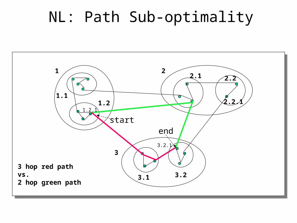
NL: Path Sub-optimality
1 2
3
1.11.2
2.1 2.2
3.1 3.2
2.2.1
3 hop red pathvs.2 hop green path
startend
3.2.1
1.2.1
NL: AS Categories
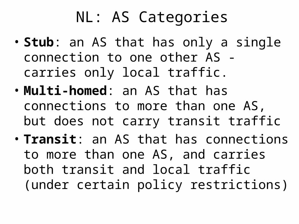
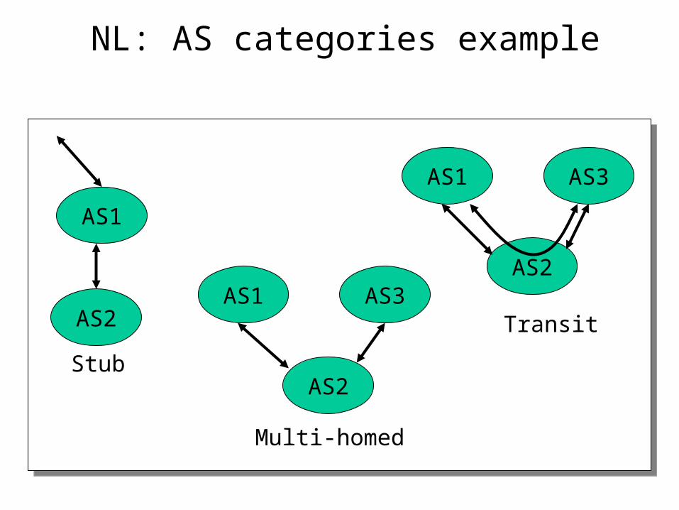
• Stub: an AS that has only a single connection to one other AS - carries only local traffic.
• Multi-homed: an AS that has connections to more than one AS, but does not carry transit traffic
• Transit: an AS that has connections to more than one AS, and carries both transit and local traffic (under certain policy restrictions)
NL: AS categories example
AS1
AS3AS2
AS1
AS2
AS3AS1
AS2
Stub
Multi-homed
Transit
NL: IP route lookups
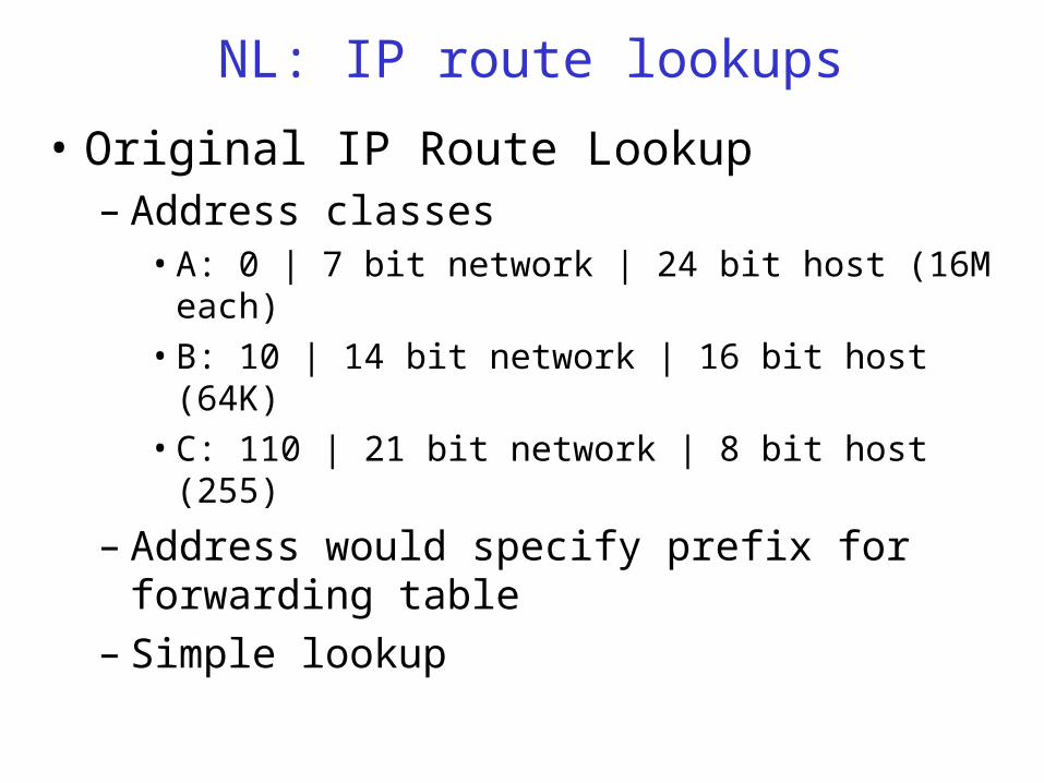
• Original IP Route Lookup – Address classes
• A: 0 | 7 bit network | 24 bit host (16M each)
• B: 10 | 14 bit network | 16 bit host (64K)
• C: 110 | 21 bit network | 8 bit host (255)
– Address would specify prefix for forwarding table– Simple lookup
NL: Original IP Route Lookup – Example
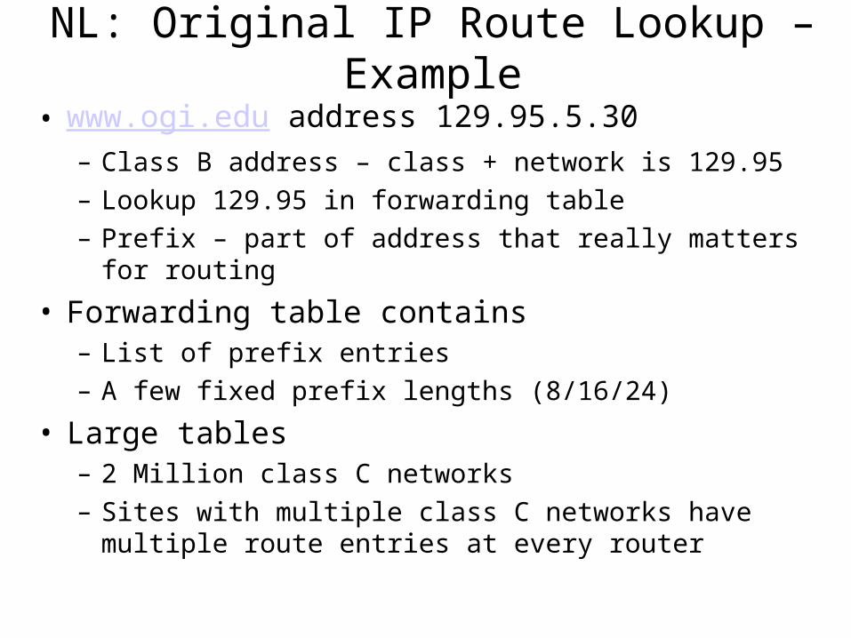
• www.ogi.edu address 129.95.5.30– Class B address – class + network is 129.95
– Lookup 129.95 in forwarding table
– Prefix – part of address that really matters for routing
• Forwarding table contains– List of prefix entries
– A few fixed prefix lengths (8/16/24)
• Large tables– 2 Million class C networks
– Sites with multiple class C networks have multiple route entries at every router
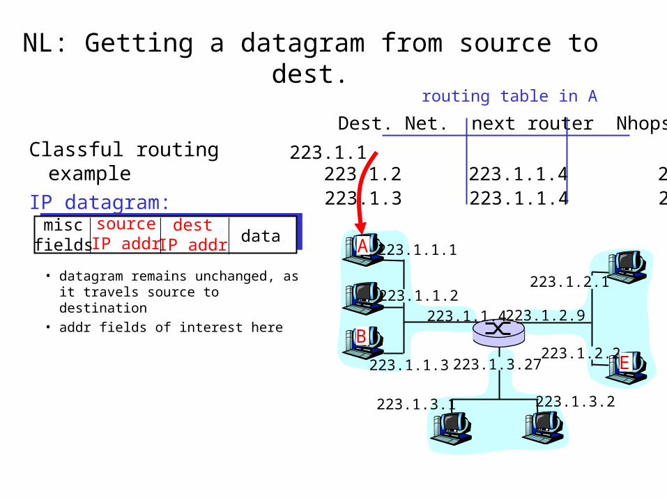
NL: Getting a datagram from source to dest.
Classful routing example
IP datagram:
223.1.1.1
223.1.1.2
223.1.1.3
223.1.1.4 223.1.2.9
223.1.2.2
223.1.2.1
223.1.3.2223.1.3.1
223.1.3.27
A
BE
miscfields
sourceIP addr
destIP addr data
• datagram remains unchanged, as it travels source to destination
• addr fields of interest here
Dest. Net. next router Nhops
223.1.1 1223.1.2 223.1.1.4 2223.1.3 223.1.1.4 2
routing table in A
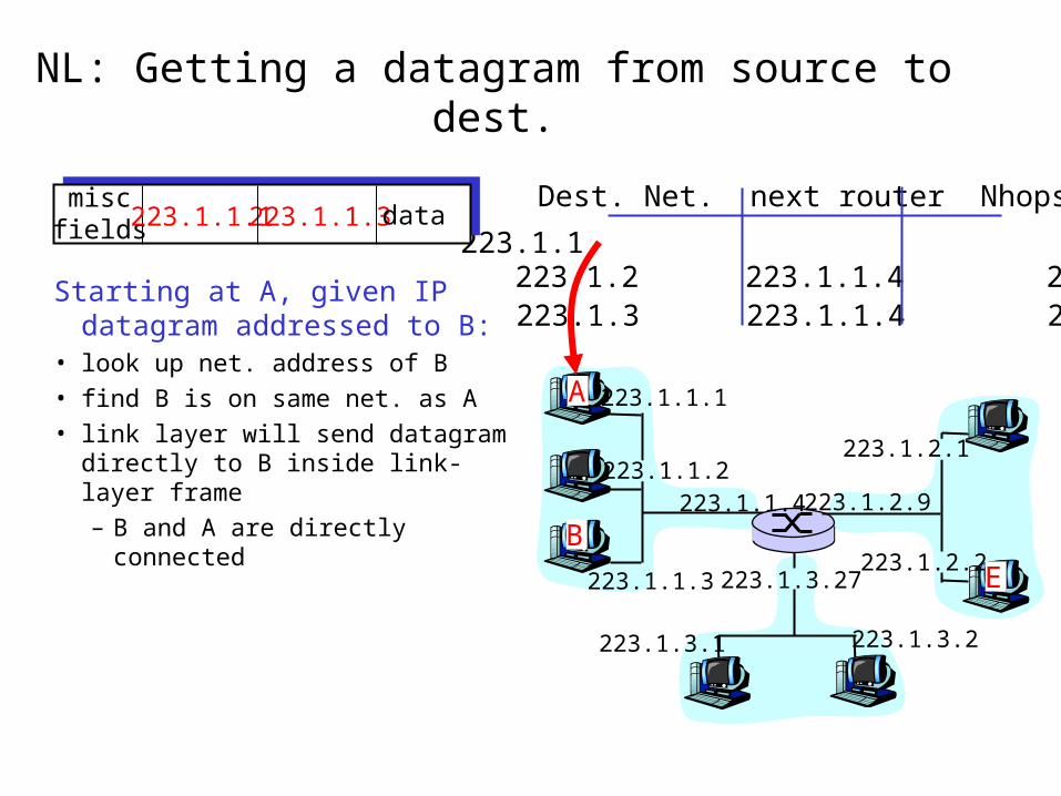
NL: Getting a datagram from source to dest.
223.1.1.1
223.1.1.2
223.1.1.3
223.1.1.4 223.1.2.9
223.1.2.2
223.1.2.1
223.1.3.2223.1.3.1
223.1.3.27
A
BE
Starting at A, given IP datagram addressed to B:
• look up net. address of B
• find B is on same net. as A
• link layer will send datagram directly to B inside link-layer frame
– B and A are directly connected
Dest. Net. next router Nhops
223.1.1 1223.1.2 223.1.1.4 2223.1.3 223.1.1.4 2
miscfields223.1.1.1223.1.1.3data
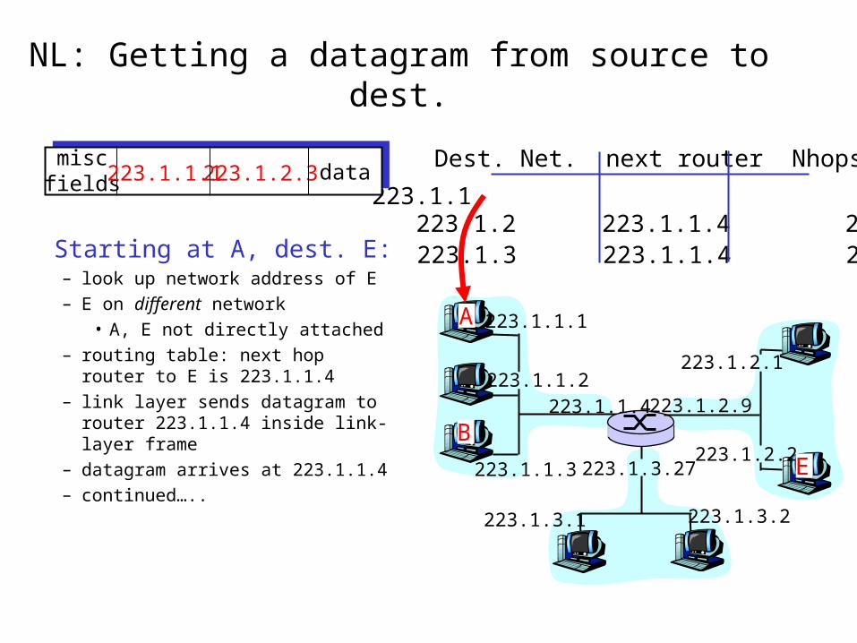
NL: Getting a datagram from source to dest.
223.1.1.1
223.1.1.2
223.1.1.3
223.1.1.4 223.1.2.9
223.1.2.2
223.1.2.1
223.1.3.2223.1.3.1
223.1.3.27
A
BE
Dest. Net. next router Nhops
223.1.1 1223.1.2 223.1.1.4 2223.1.3 223.1.1.4 2Starting at A, dest. E:
– look up network address of E– E on different network
• A, E not directly attached– routing table: next hop router to
E is 223.1.1.4 – link layer sends datagram to
router 223.1.1.4 inside link-layer frame
– datagram arrives at 223.1.1.4 – continued…..
miscfields223.1.1.1223.1.2.3 data
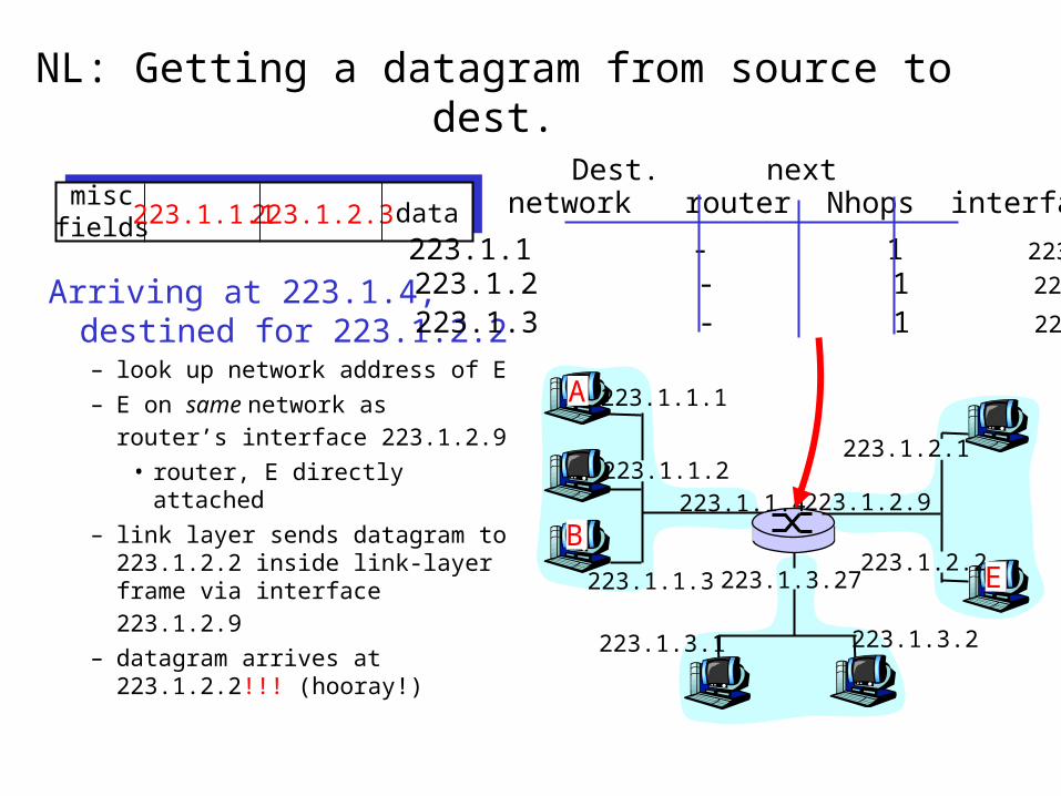
NL: Getting a datagram from source to dest.
223.1.1.1
223.1.1.2
223.1.1.3
223.1.1.4 223.1.2.9
223.1.2.2
223.1.2.1
223.1.3.2223.1.3.1
223.1.3.27
A
BE
Arriving at 223.1.4, destined for 223.1.2.2– look up network address of E
– E on same network as router’s
interface 223.1.2.9 • router, E directly attached
– link layer sends datagram to 223.1.2.2 inside link-layer
frame via interface 223.1.2.9 – datagram arrives at
223.1.2.2!!! (hooray!)
miscfields223.1.1.1223.1.2.3 data network router Nhops interface
223.1.1 - 1 223.1.1.4 223.1.2 - 1 223.1.2.9
223.1.3 - 1 223.1.3.27
Dest. next
NL: CIDR
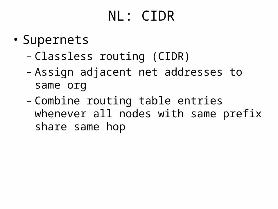
• Supernets– Classless routing (CIDR)– Assign adjacent net addresses to same org– Combine routing table entries whenever all nodes
with same prefix share same hop
NL: CIDR and IP route lookups
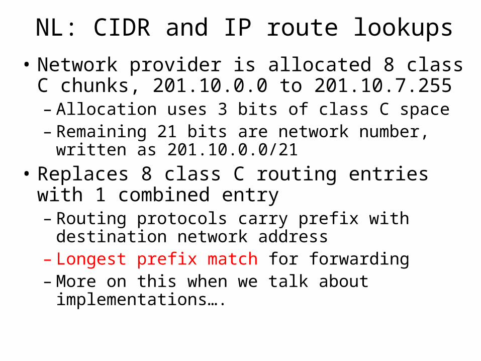
• Network provider is allocated 8 class C chunks, 201.10.0.0 to 201.10.7.255– Allocation uses 3 bits of class C space– Remaining 21 bits are network number, written as
201.10.0.0/21
• Replaces 8 class C routing entries with 1 combined entry– Routing protocols carry prefix with destination
network address– Longest prefix match for forwarding– More on this when we talk about implementations….
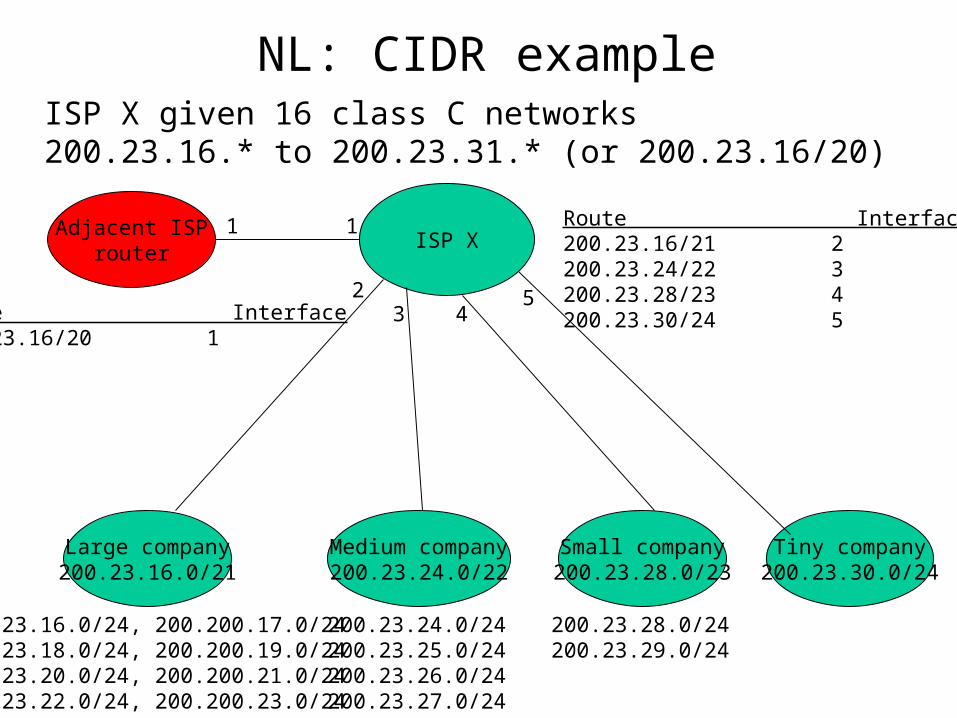
NL: CIDR exampleISP X given 16 class C networks 200.23.16.* to 200.23.31.* (or 200.23.16/20)
200.23.16.0/24, 200.200.17.0/24200.23.18.0/24, 200.200.19.0/24200.23.20.0/24, 200.200.21.0/24200.23.22.0/24, 200.200.23.0/24
Large company200.23.16.0/21
Medium company200.23.24.0/22
200.23.24.0/24200.23.25.0/24200.23.26.0/24200.23.27.0/24
Small company200.23.28.0/23
200.23.28.0/24200.23.29.0/24
Tiny company200.23.30.0/24
Adjacent ISProuter
ISP X
Route Interface200.23.16/20 1
1 Route Interface200.23.16/21 2200.23.24/22 3200.23.28/23 4200.23.30/24 5
1
23 4
5
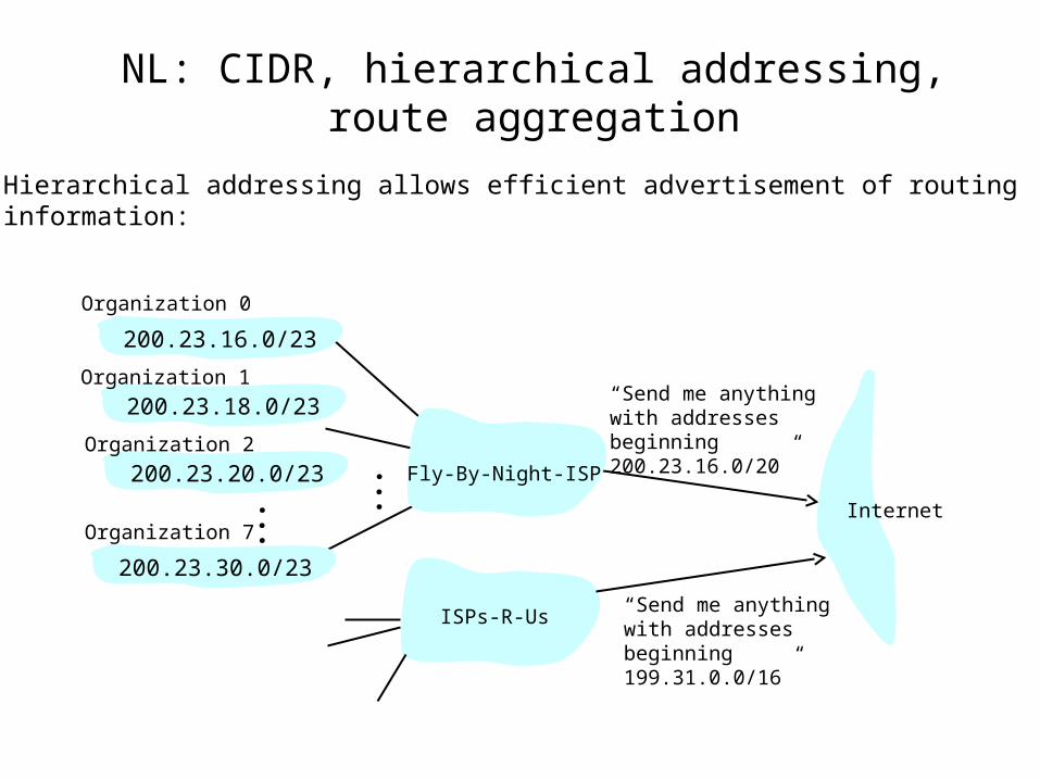
NL: CIDR, hierarchical addressing, route aggregation
“ Send me anythingwith addresses beginning 200.23.16.0/20”
200.23.16.0/23
200.23.18.0/23
200.23.30.0/23
Fly-By-Night-ISP
Organization 0
Organization 7Internet
Organization 1
ISPs-R-Us“ Send me anythingwith addresses beginning 199.31.0.0/16”
200.23.20.0/23Organization 2
...
...
Hierarchical addressing allows efficient advertisement of routing information:
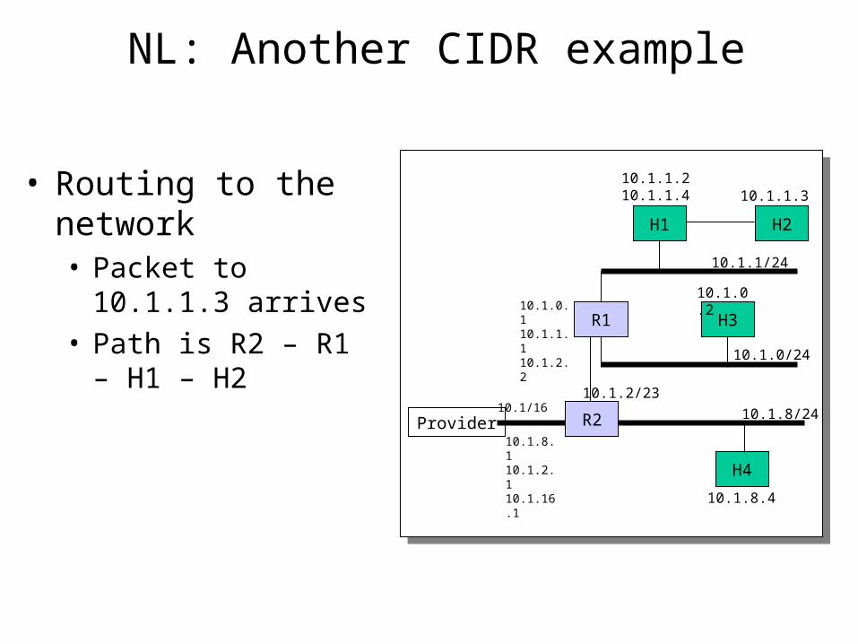
NL: Another CIDR example
H2
H3
H4
R1
10.1.1/24
10.1.1.210.1.1.4
Provider10.1/16 10.1.8/24
10.1.0/24
10.1.1.3
10.1.2/23
R2
10.1.0.2
10.1.8.4
10.1.0.110.1.1.110.1.2.2
10.1.8.110.1.2.110.1.16.1
H1
• Routing to the network • Packet to 10.1.1.3
arrives• Path is R2 – R1 – H1
– H2
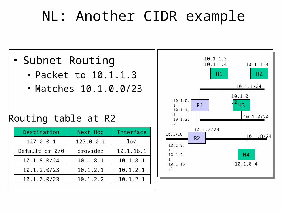
NL: Another CIDR example
Routing table at R2
H2
H3
H4
R1
10.1.1/24
10.1/16 10.1.8/24
10.1.0/24
10.1.1.3
10.1.2/23
R2
10.1.0.2
10.1.8.4
10.1.0.110.1.1.110.1.2.2
10.1.8.110.1.2.110.1.16.1
H1
Destination Next Hop Interface
127.0.0.1 127.0.0.1 lo0
Default or 0/0 provider 10.1.16.1
10.1.8.0/24 10.1.8.1 10.1.8.1
10.1.2.0/23 10.1.2.1 10.1.2.1
10.1.0.0/23 10.1.2.2 10.1.2.1
• Subnet Routing• Packet to 10.1.1.3• Matches 10.1.0.0/23
10.1.1.210.1.1.4
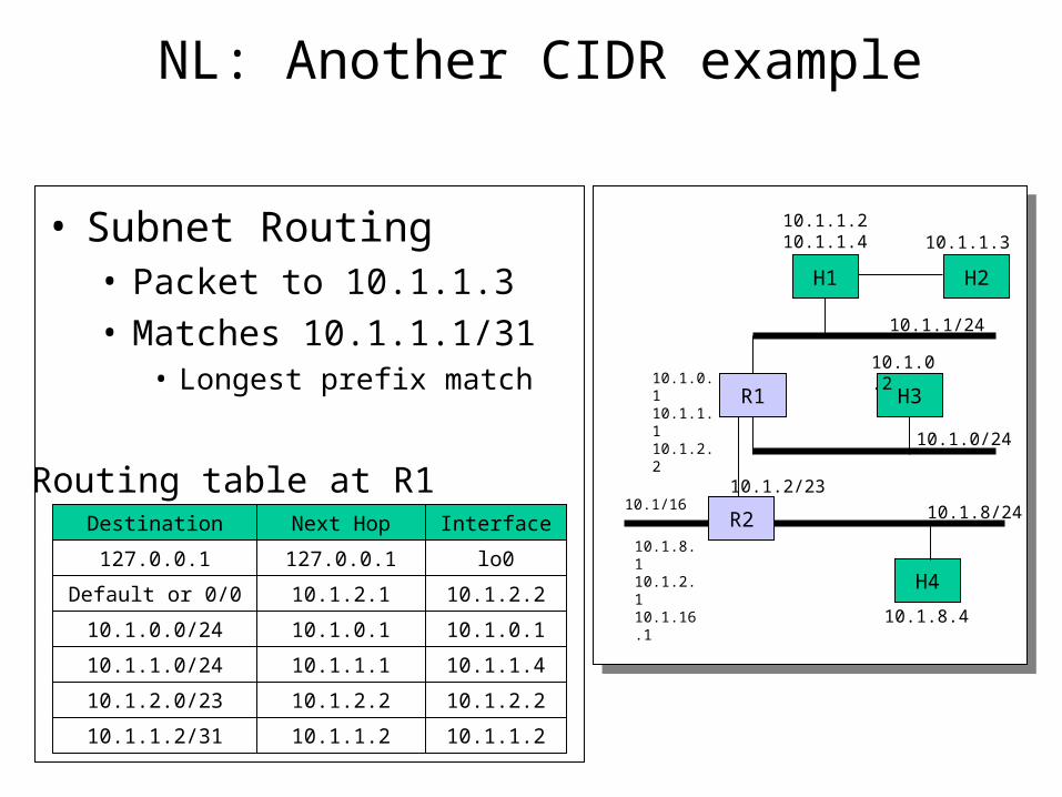
NL: Another CIDR example
H2
H3
H4
R1
10.1.1/24
10.1/16 10.1.8/24
10.1.0/24
10.1.1.3
10.1.2/23
R2
10.1.0.2
10.1.8.4
10.1.0.110.1.1.110.1.2.2
10.1.8.110.1.2.110.1.16.1
H1
Routing table at R1Destination Next Hop Interface
127.0.0.1 127.0.0.1 lo0
Default or 0/0 10.1.2.1 10.1.2.2
10.1.0.0/24 10.1.0.1 10.1.0.1
10.1.1.0/24 10.1.1.1 10.1.1.4
10.1.2.0/23 10.1.2.2 10.1.2.2
• Subnet Routing• Packet to 10.1.1.3• Matches 10.1.1.1/31
• Longest prefix match
10.1.1.2/31 10.1.1.2 10.1.1.2
10.1.1.210.1.1.4
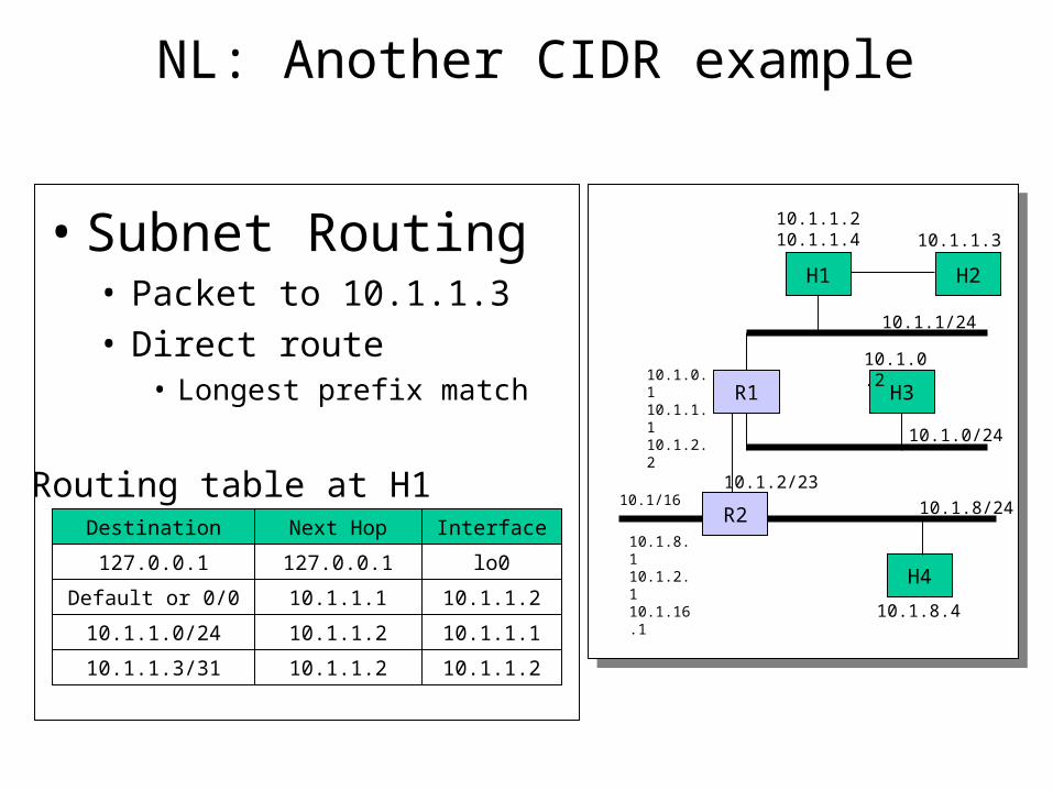
NL: Another CIDR example
H2
H3
H4
R1
10.1.1/24
10.1/16 10.1.8/24
10.1.0/24
10.1.1.3
10.1.2/23
R2
10.1.0.2
10.1.8.4
10.1.0.110.1.1.110.1.2.2
10.1.8.110.1.2.110.1.16.1
H1
Routing table at H1Destination Next Hop Interface
127.0.0.1 127.0.0.1 lo0
Default or 0/0 10.1.1.1 10.1.1.2
10.1.1.0/24 10.1.1.2 10.1.1.1
10.1.1.3/31 10.1.1.2 10.1.1.2
• Subnet Routing• Packet to 10.1.1.3• Direct route
• Longest prefix match
10.1.1.210.1.1.4
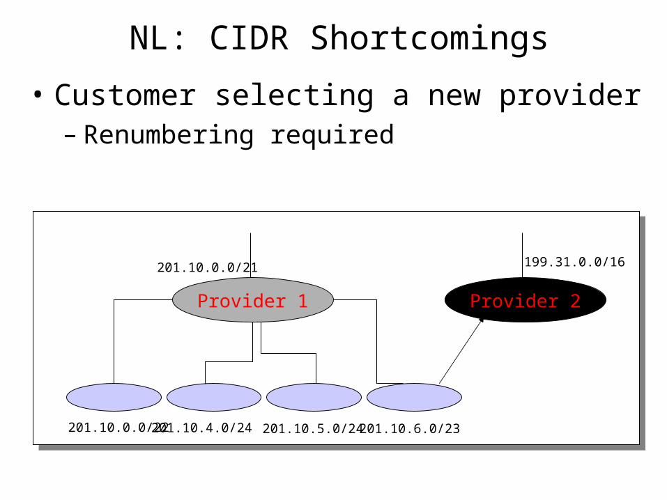
NL: CIDR Shortcomings
• Customer selecting a new provider– Renumbering required
201.10.0.0/21
201.10.0.0/22 201.10.4.0/24 201.10.5.0/24 201.10.6.0/23
Provider 1 Provider 2
199.31.0.0/16
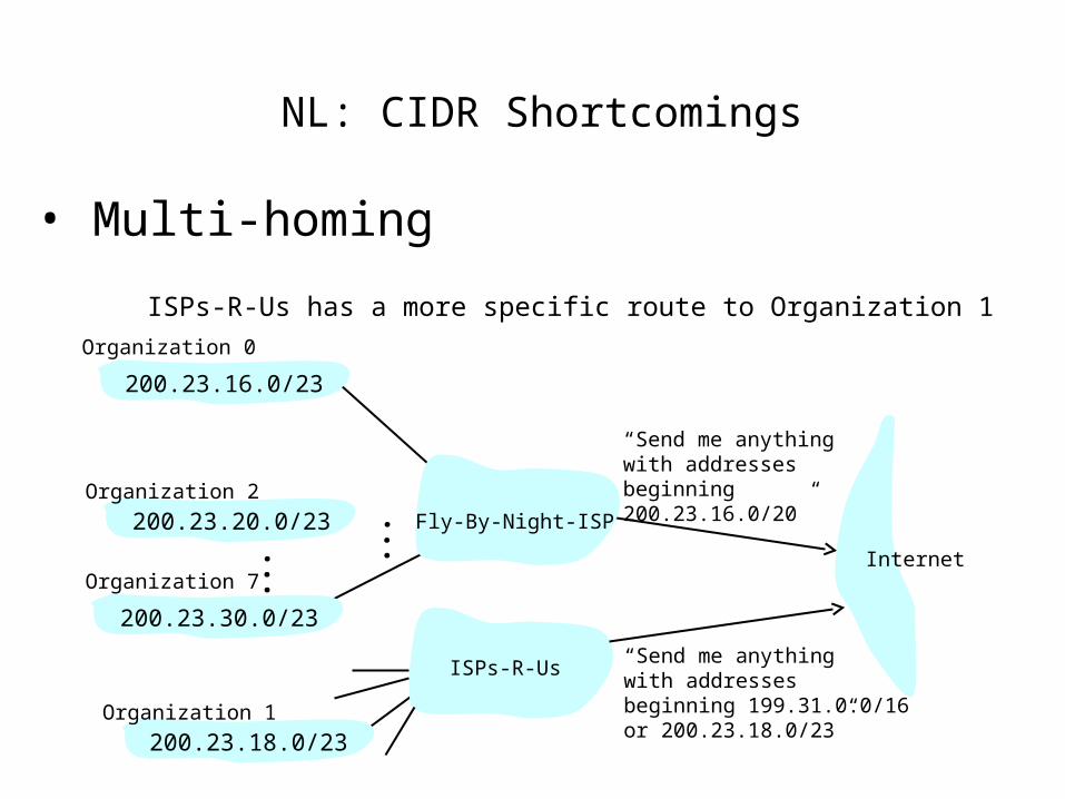
NL: CIDR Shortcomings
• Multi-homing
“ Send me anythingwith addresses beginning 200.23.16.0/20”
200.23.16.0/23
200.23.18.0/23
200.23.30.0/23
Fly-By-Night-ISP
Organization 0
Organization 7Internet
Organization 1
ISPs-R-Us“ Send me anythingwith addresses beginning 199.31.0.0/16or 200.23.18.0/23”
200.23.20.0/23Organization 2
...
...
ISPs-R-Us has a more specific route to Organization 1
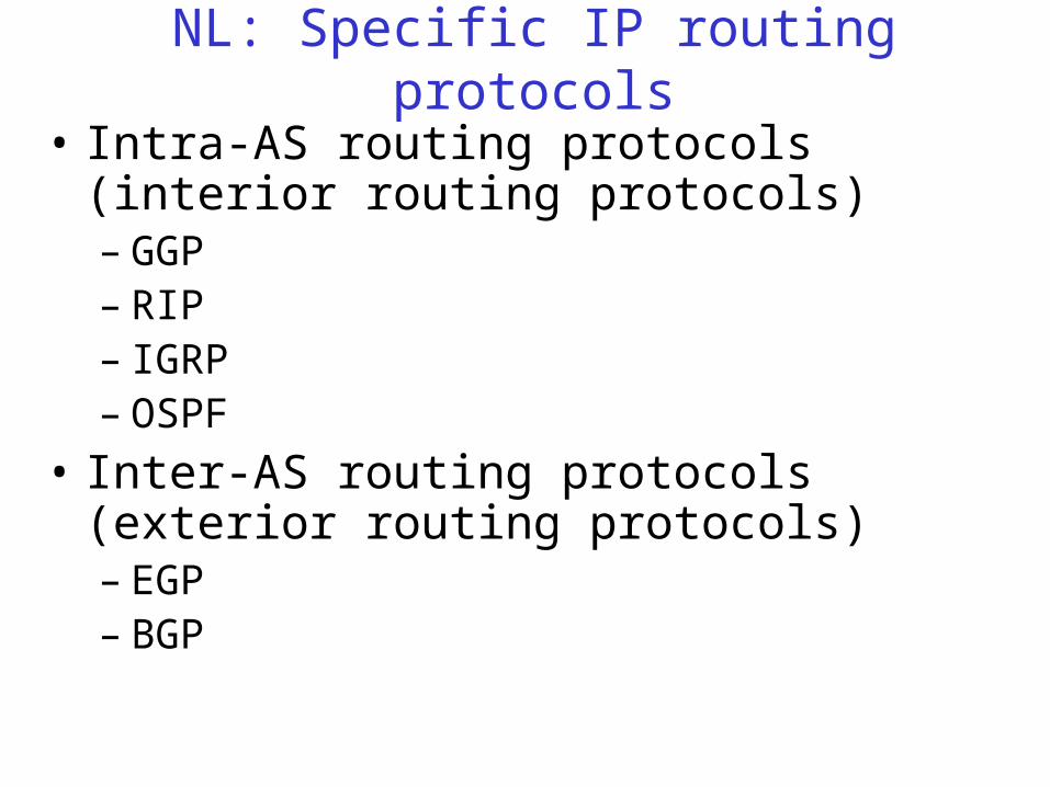
NL: Specific IP routing protocols
• Intra-AS routing protocols (interior routing protocols)– GGP– RIP– IGRP– OSPF
• Inter-AS routing protocols (exterior routing protocols)– EGP– BGP
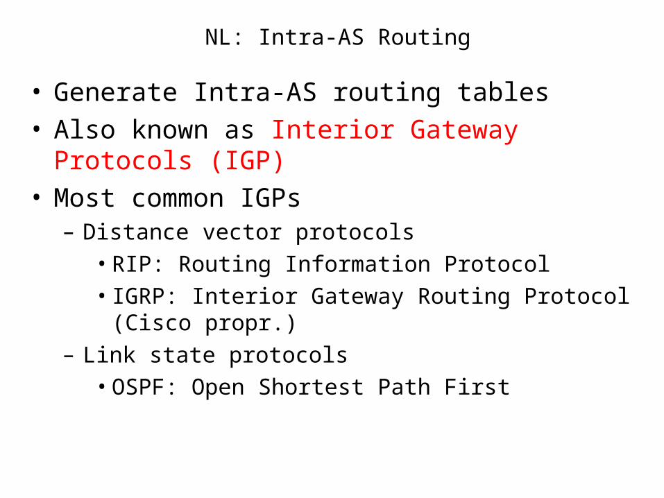
NL: Intra-AS Routing
• Generate Intra-AS routing tables• Also known as Interior Gateway Protocols (IGP)• Most common IGPs
– Distance vector protocols
• RIP: Routing Information Protocol
• IGRP: Interior Gateway Routing Protocol (Cisco propr.)
– Link state protocols
• OSPF: Open Shortest Path First
NL: Intra-AS Distance Vector Protocols
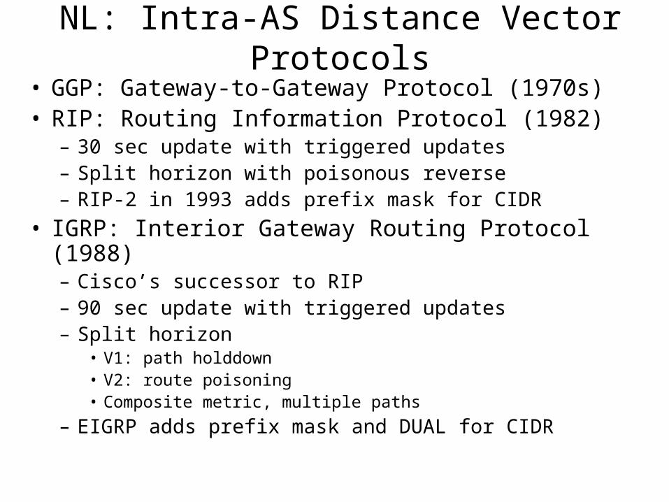
• GGP: Gateway-to-Gateway Protocol (1970s)• RIP: Routing Information Protocol (1982)
– 30 sec update with triggered updates– Split horizon with poisonous reverse– RIP-2 in 1993 adds prefix mask for CIDR
• IGRP: Interior Gateway Routing Protocol (1988)– Cisco’s successor to RIP– 90 sec update with triggered updates– Split horizon
• V1: path holddown• V2: route poisoning• Composite metric, multiple paths
– EIGRP adds prefix mask and DUAL for CIDR
NL: RIP (Routing Information Protocol)
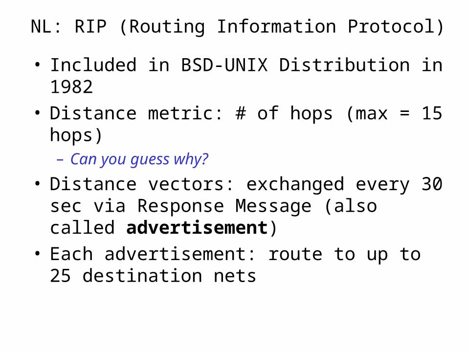
• Included in BSD-UNIX Distribution in 1982• Distance metric: # of hops (max = 15 hops)
– Can you guess why?
• Distance vectors: exchanged every 30 sec via Response Message (also called advertisement)
• Each advertisement: route to up to 25 destination nets
NL: RIP: Link Failure and Recovery
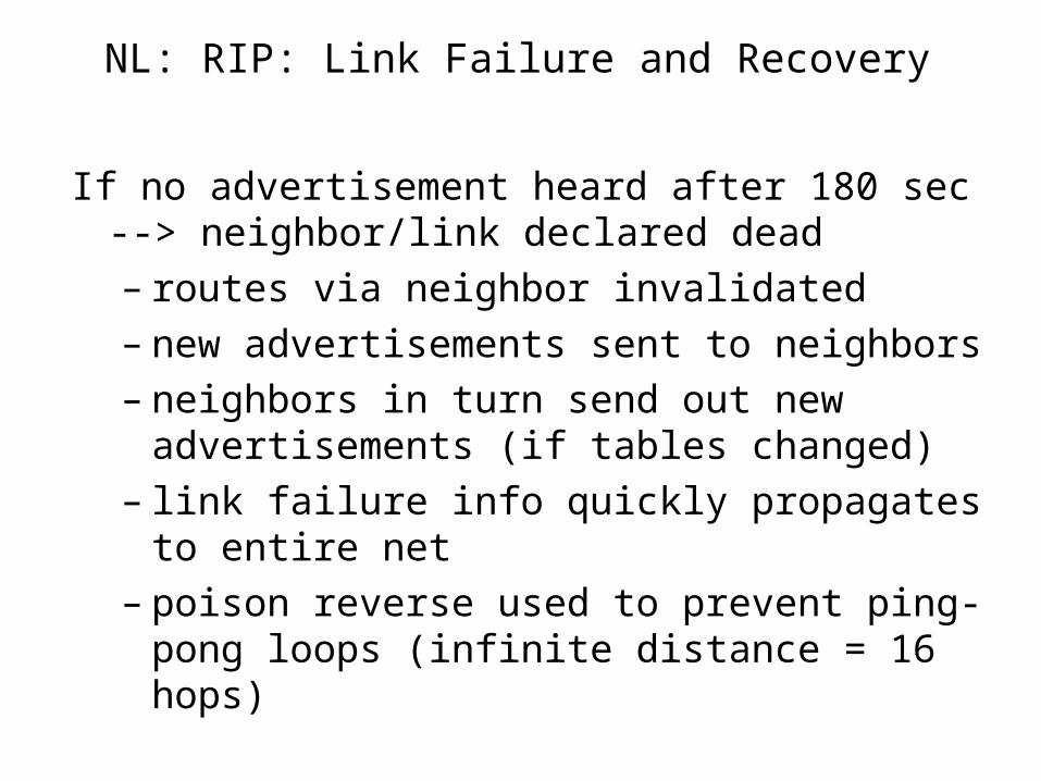
If no advertisement heard after 180 sec --> neighbor/link declared dead– routes via neighbor invalidated– new advertisements sent to neighbors– neighbors in turn send out new advertisements (if
tables changed)– link failure info quickly propagates to entire net– poison reverse used to prevent ping-pong loops
(infinite distance = 16 hops)
NL: RIP Table processing
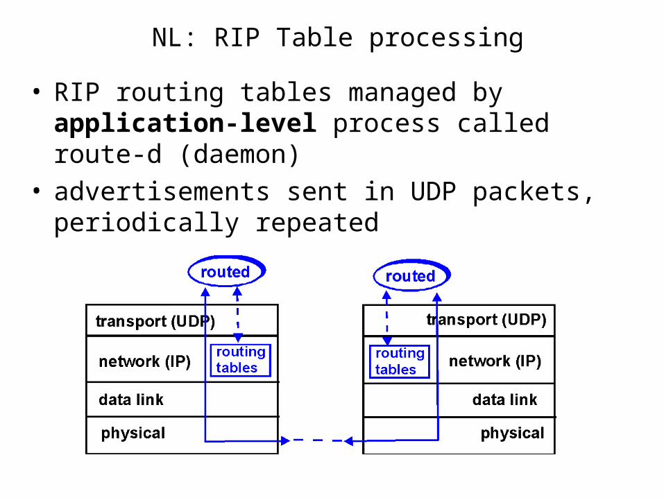
• RIP routing tables managed by application-level process called route-d (daemon)
• advertisements sent in UDP packets, periodically repeated
NL: RIP Table example (continued)
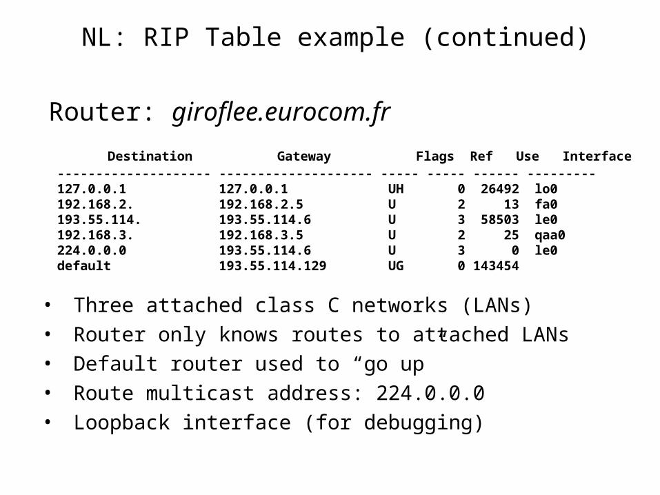
Router: giroflee.eurocom.fr
• Three attached class C networks (LANs)• Router only knows routes to attached LANs• Default router used to “go up”• Route multicast address: 224.0.0.0• Loopback interface (for debugging)
Destination Gateway Flags Ref Use Interface -------------------- -------------------- ----- ----- ------ --------- 127.0.0.1 127.0.0.1 UH 0 26492 lo0 192.168.2. 192.168.2.5 U 2 13 fa0 193.55.114. 193.55.114.6 U 3 58503 le0 192.168.3. 192.168.3.5 U 2 25 qaa0 224.0.0.0 193.55.114.6 U 3 0 le0 default 193.55.114.129 UG 0 143454
NL: IGRP (Interior Gateway Routing Protocol)
• CISCO proprietary; successor of RIP (mid 80s)
• Distance Vector, like RIP
• several cost metrics (delay, bandwidth, reliability, load etc)
• uses TCP to exchange routing updates
• Loop-free routing via Distributed Updating Alg. (DUAL) based on diffused computation
NL: Intra-AS Link State Protocols
• OSPF
• Hierarchical OSPF
NL: OSPF (Open Shortest Path First)
• “open”: publicly available• Uses Link State algorithm
– LS packet dissemination
– Topology map at each node
– Route computation using Dijkstra’s algorithm
• OSPF advertisement carries one entry per neighbor router
• Advertisements disseminated to entire AS (via flooding)
NL: OSPF “advanced” features (not in RIP)
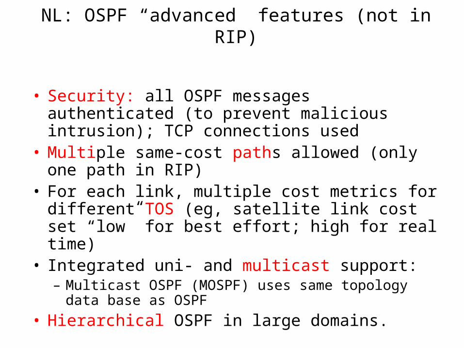
• Security: all OSPF messages authenticated (to prevent malicious intrusion); TCP connections used
• Multiple same-cost paths allowed (only one path in RIP)
• For each link, multiple cost metrics for different TOS (eg, satellite link cost set “low” for best effort; high for real time)
• Integrated uni- and multicast support: – Multicast OSPF (MOSPF) uses same topology data base as
OSPF
• Hierarchical OSPF in large domains.
NL: Hierarchical OSPF
NL: Hierarchical OSPF
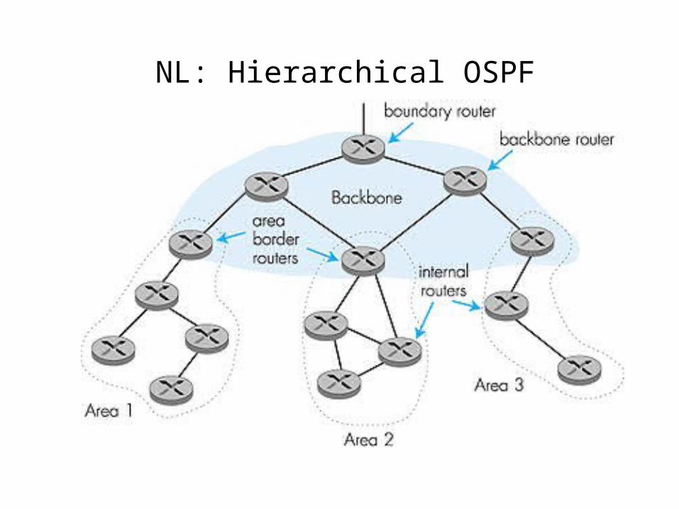
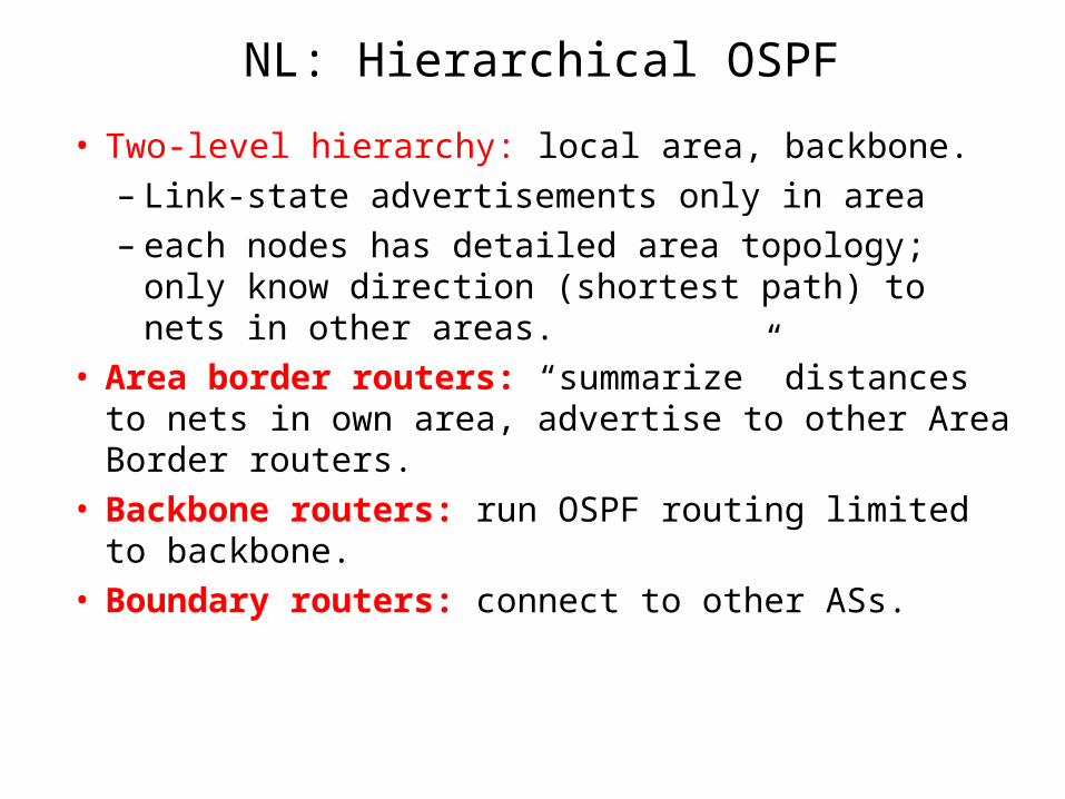
• Two-level hierarchy: local area, backbone.– Link-state advertisements only in area – each nodes has detailed area topology; only know
direction (shortest path) to nets in other areas.• Area border routers: “summarize” distances to nets
in own area, advertise to other Area Border routers.• Backbone routers: run OSPF routing limited to
backbone.• Boundary routers: connect to other ASs.
NL: Inter-AS routing
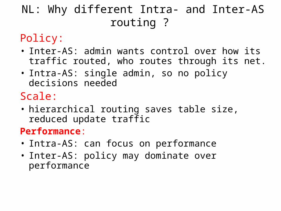
NL: Why different Intra- and Inter-AS routing ?
Policy: • Inter-AS: admin wants control over how its traffic
routed, who routes through its net. • Intra-AS: single admin, so no policy decisions needed
Scale:• hierarchical routing saves table size, reduced update
trafficPerformance: • Intra-AS: can focus on performance• Inter-AS: policy may dominate over performance
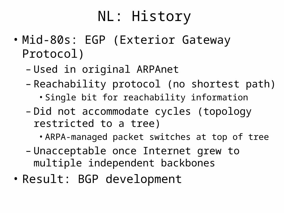
NL: History
• Mid-80s: EGP (Exterior Gateway Protocol)– Used in original ARPAnet – Reachability protocol (no shortest path)
• Single bit for reachability information
– Did not accommodate cycles (topology restricted to a tree)
• ARPA-managed packet switches at top of tree
– Unacceptable once Internet grew to multiple independent backbones
• Result: BGP development
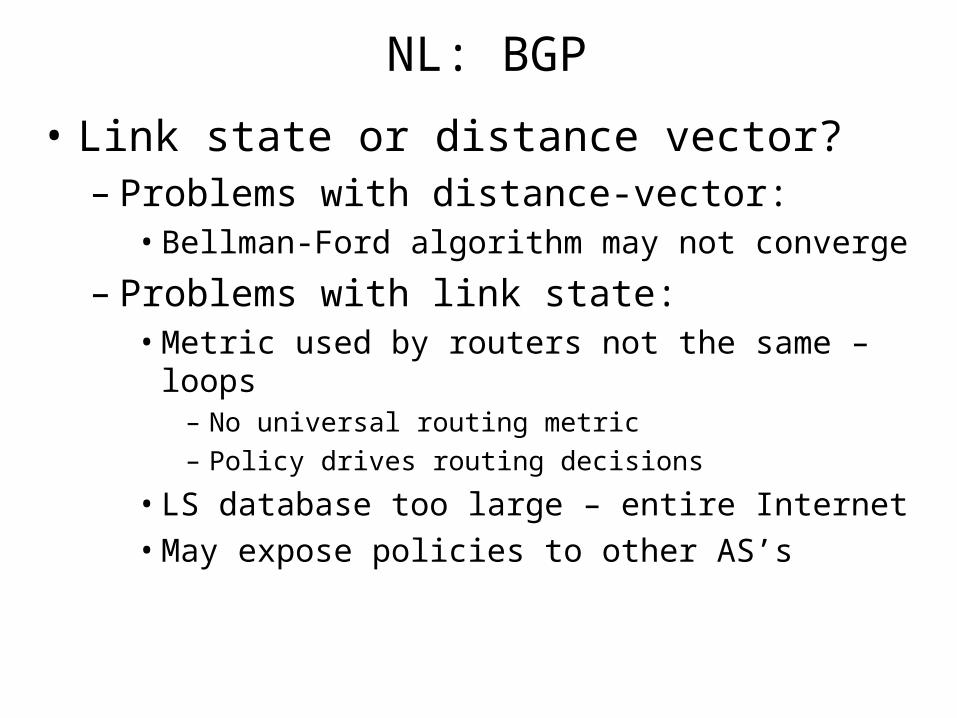
NL: BGP
• Link state or distance vector?– Problems with distance-vector:
• Bellman-Ford algorithm may not converge
– Problems with link state:• Metric used by routers not the same – loops
– No universal routing metric
– Policy drives routing decisions
• LS database too large – entire Internet
• May expose policies to other AS’s
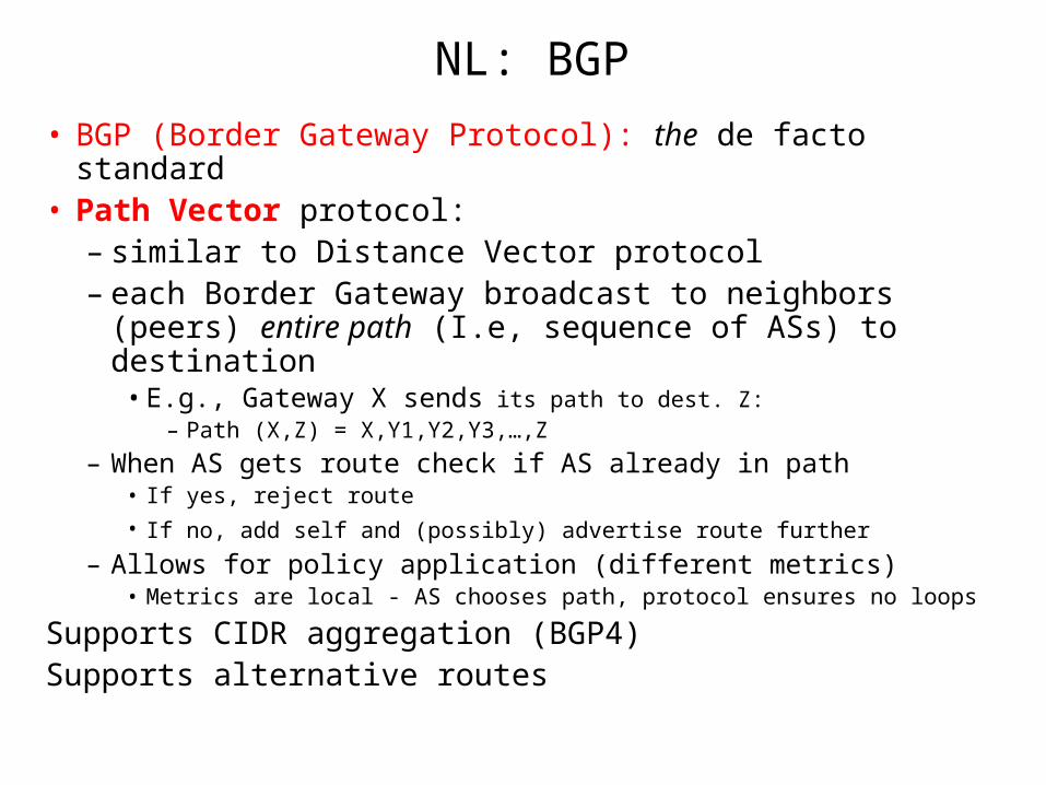
NL: BGP
• BGP (Border Gateway Protocol): the de facto standard• Path Vector protocol:
– similar to Distance Vector protocol– each Border Gateway broadcast to neighbors (peers) entire
path (I.e, sequence of ASs) to destination• E.g., Gateway X sends its path to dest. Z:
– Path (X,Z) = X,Y1,Y2,Y3,…,Z
– When AS gets route check if AS already in path• If yes, reject route
• If no, add self and (possibly) advertise route further – Allows for policy application (different metrics)
• Metrics are local - AS chooses path, protocol ensures no loops
Supports CIDR aggregation (BGP4)Supports alternative routes
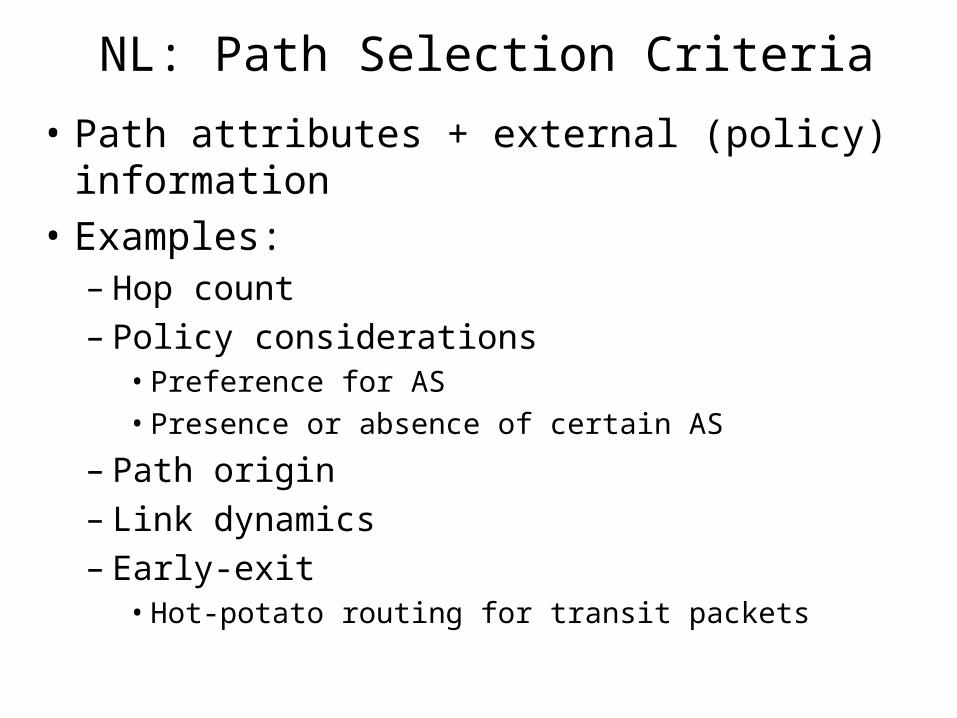
NL: Path Selection Criteria
• Path attributes + external (policy) information
• Examples:– Hop count– Policy considerations
• Preference for AS
• Presence or absence of certain AS
– Path origin– Link dynamics– Early-exit
• Hot-potato routing for transit packets
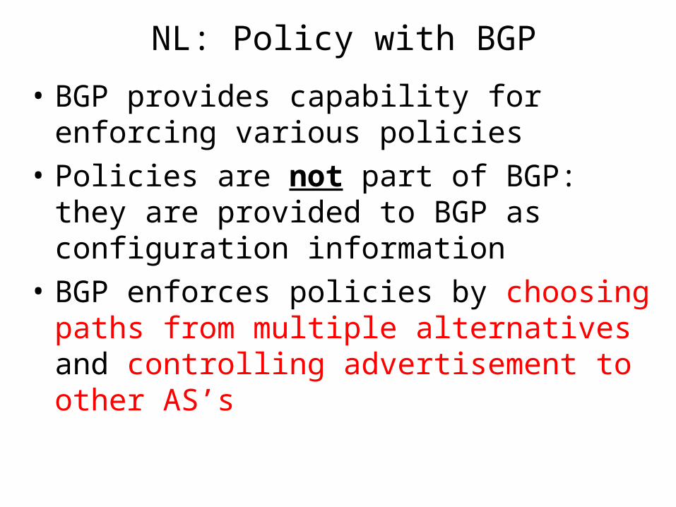
NL: Policy with BGP
• BGP provides capability for enforcing various policies
• Policies are not part of BGP: they are provided to BGP as configuration information
• BGP enforces policies by choosing paths from multiple alternatives and controlling advertisement to other AS’s
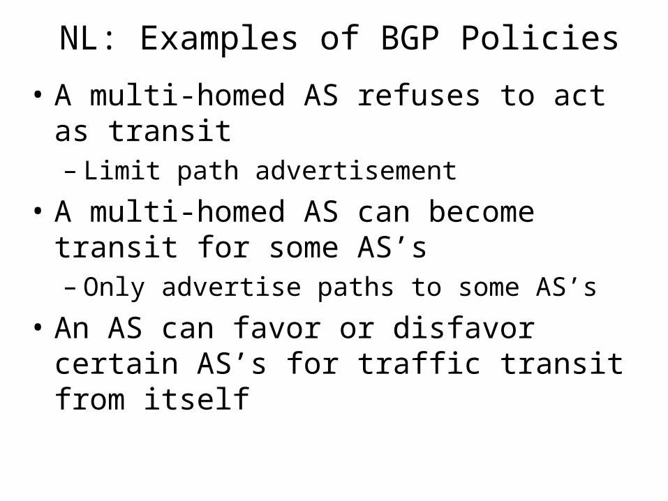
NL: Examples of BGP Policies
• A multi-homed AS refuses to act as transit– Limit path advertisement
• A multi-homed AS can become transit for some AS’s– Only advertise paths to some AS’s
• An AS can favor or disfavor certain AS’s for traffic transit from itself
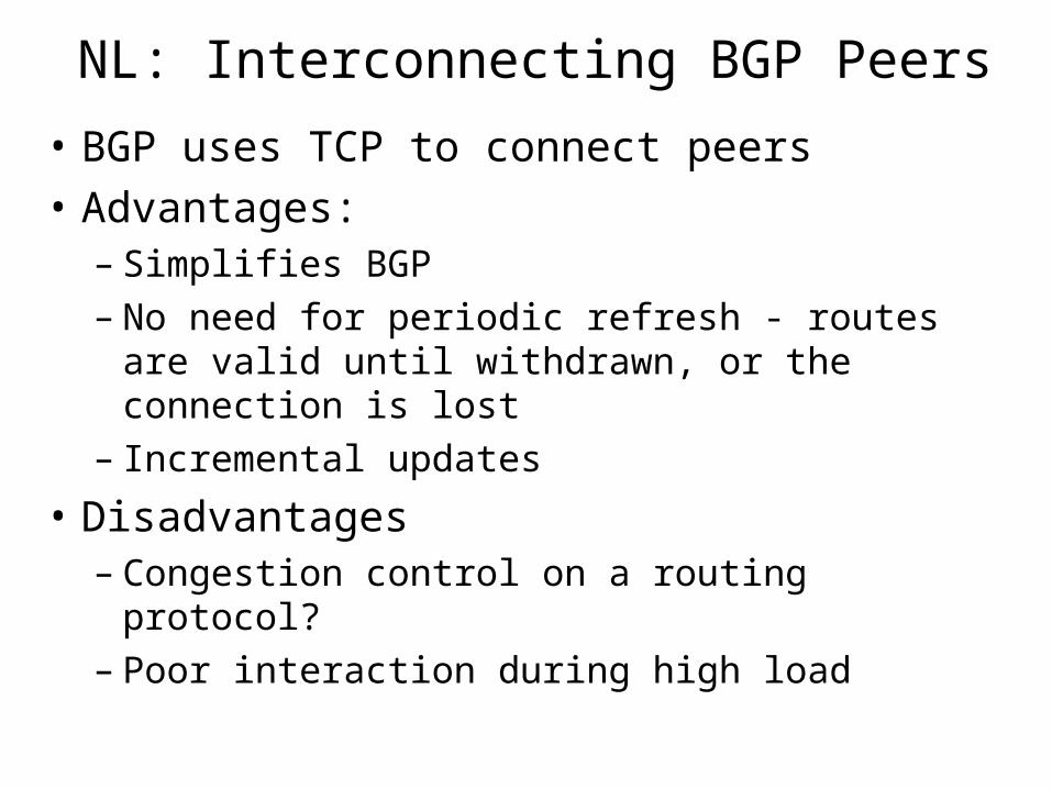
NL: Interconnecting BGP Peers
• BGP uses TCP to connect peers
• Advantages:– Simplifies BGP– No need for periodic refresh - routes are valid until
withdrawn, or the connection is lost– Incremental updates
• Disadvantages– Congestion control on a routing protocol?– Poor interaction during high load
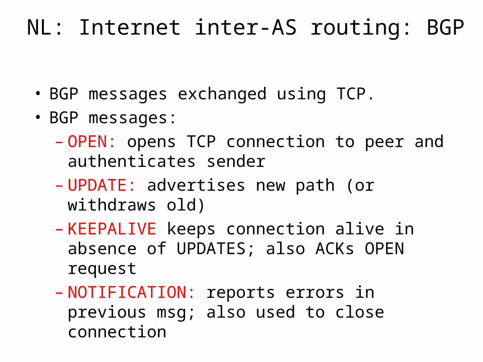
NL: Internet inter-AS routing: BGP
• BGP messages exchanged using TCP.• BGP messages:
– OPEN: opens TCP connection to peer and authenticates sender
– UPDATE: advertises new path (or withdraws old)– KEEPALIVE keeps connection alive in absence of
UPDATES; also ACKs OPEN request– NOTIFICATION: reports errors in previous msg;
also used to close connection
NL: IP summary
• Security
• Error detection
• Delivery semantics
• Quality-of-service
• Fragmentation
• Addressing
• Routing
NL: IPv6
• Redefine functions of IP (version 4)– Remove ancillary functionality– Add missing, but essential functionality– Recall, functions of IPv4
• What changes should be made in….– IP addressing– IP delivery semantics– IP quality of service– IP security– IP routing– IP fragmentation– IP error detection
NL: IPv6
• Initial motivation: 32-bit address space completely allocated by 2008.
• Additional motivation:– header format helps speed processing/forwarding– header changes to facilitate QoS – new “anycast” address: route to “best” of several
replicated servers
• IPv6 datagram format: – fixed-length 40 byte header– no fragmentation allowed
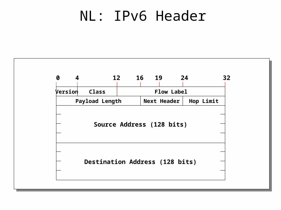
NL: IPv6 Header
Source Address (128 bits)
Destination Address (128 bits)
0 4 16 24 32
Version Class Flow Label
Payload Length Next Header Hop Limit
12 19
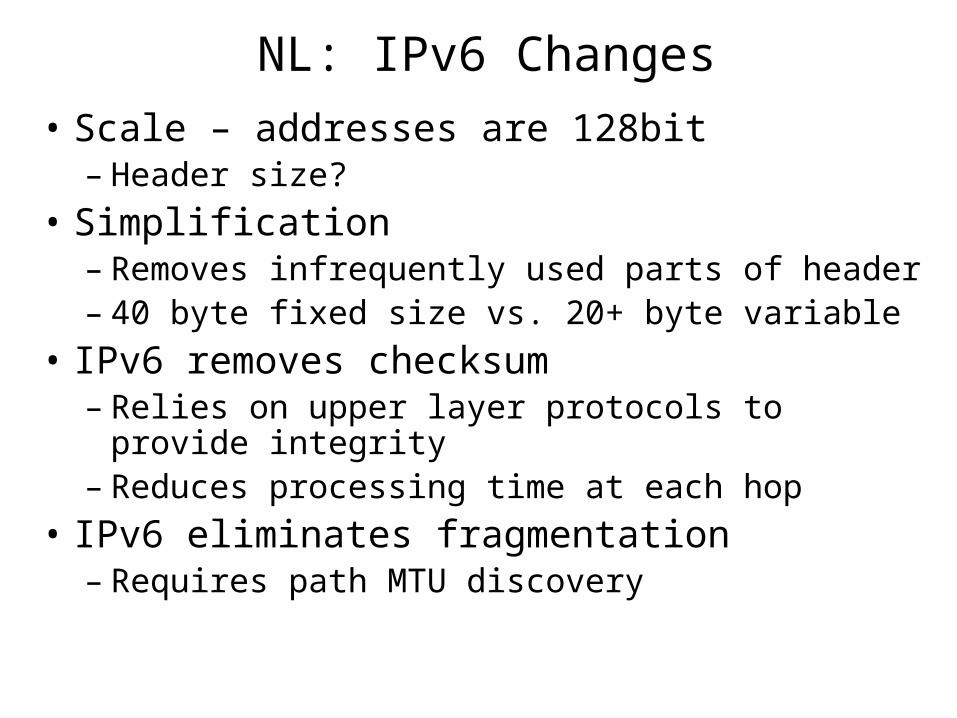
NL: IPv6 Changes
• Scale – addresses are 128bit– Header size?
• Simplification– Removes infrequently used parts of header– 40 byte fixed size vs. 20+ byte variable
• IPv6 removes checksum– Relies on upper layer protocols to provide integrity– Reduces processing time at each hop
• IPv6 eliminates fragmentation– Requires path MTU discovery
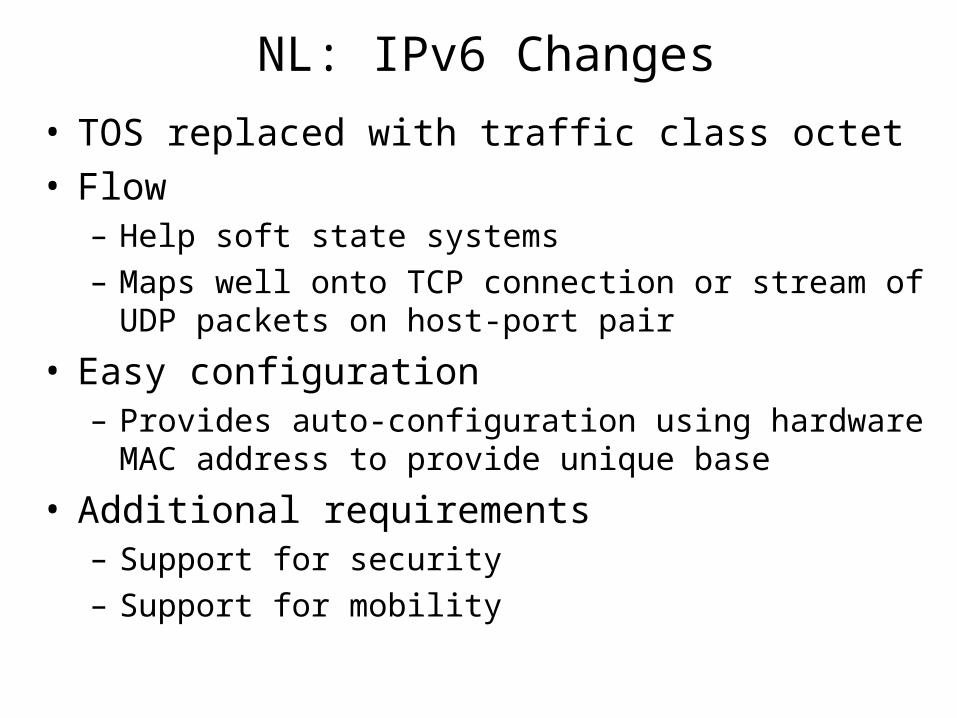
NL: IPv6 Changes
• TOS replaced with traffic class octet• Flow
– Help soft state systems
– Maps well onto TCP connection or stream of UDP packets on host-port pair
• Easy configuration– Provides auto-configuration using hardware MAC address to
provide unique base
• Additional requirements– Support for security
– Support for mobility
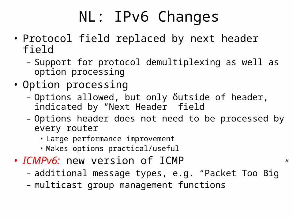
NL: IPv6 Changes
• Protocol field replaced by next header field– Support for protocol demultiplexing as well as option
processing
• Option processing– Options allowed, but only outside of header, indicated by
“Next Header” field– Options header does not need to be processed by every router
• Large performance improvement• Makes options practical/useful
• ICMPv6: new version of ICMP– additional message types, e.g. “Packet Too Big”– multicast group management functions
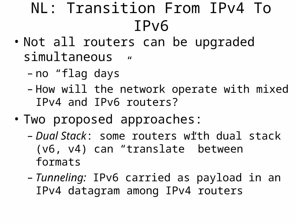
NL: Transition From IPv4 To IPv6
• Not all routers can be upgraded simultaneous– no “flag days”– How will the network operate with mixed IPv4 and
IPv6 routers?
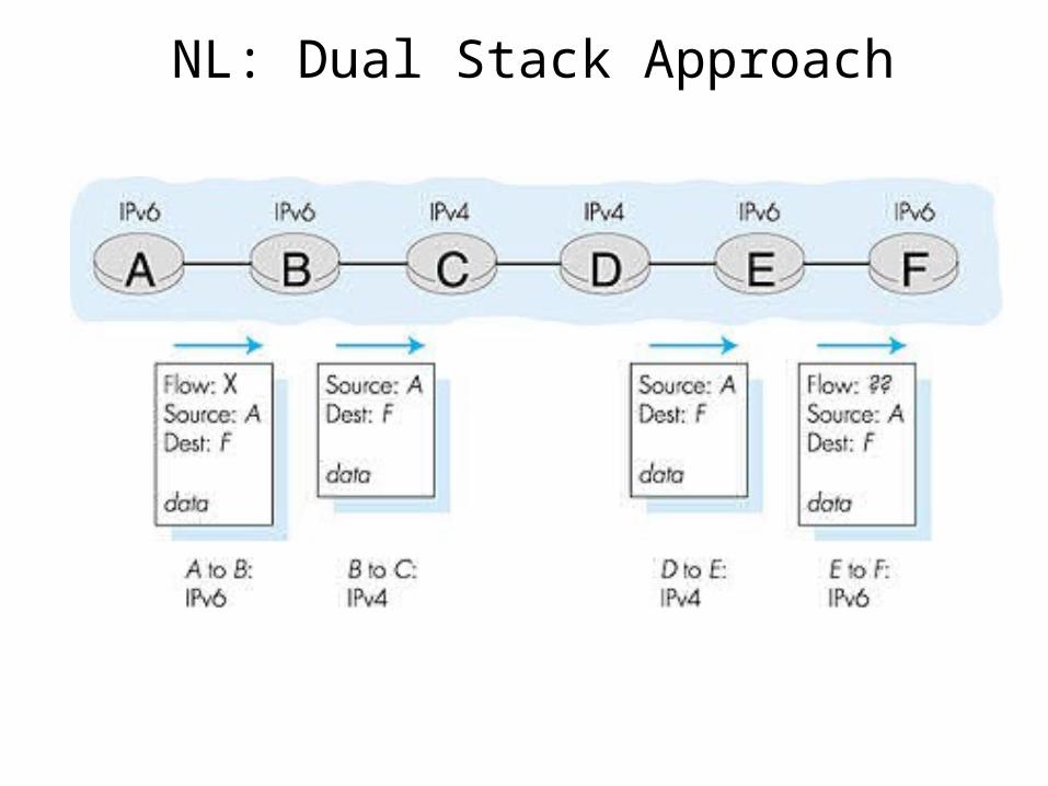
• Two proposed approaches:– Dual Stack: some routers with dual stack (v6, v4) can
“translate” between formats– Tunneling: IPv6 carried as payload in an IPv4
datagram among IPv4 routers
NL: Dual Stack Approach
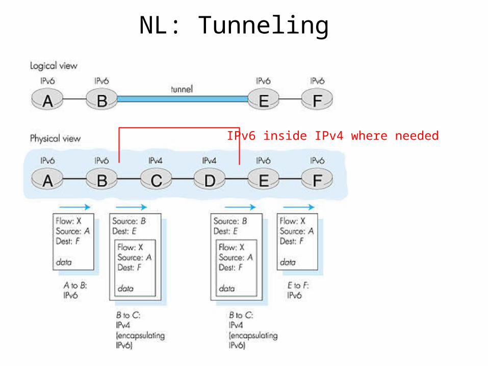
NL: Tunneling
IPv6 inside IPv4 where needed
Related Documents