Course Material –Lecture Notes CS 6551 Computer Networks – Unit-I Page 1 UNIT I FUNDAMENTALS & LINK LAYER Building a network: A computer network or data network is a telecommunications network which allows computers to exchange data. In computer networks, networked computing devices pass data to each other along network links (data connections). Data is transferred in the form of packets. The connections between nodes are established using either cable media or wireless media. The best- known computer network is the Internet. To build a computer network is defining what a network is and understanding how it is used to help a business meet its objectives. A network is a connected collection of devices and end systems, such as computers and servers, which can communicate with each other. These are the four major categories of physical components in a computer network: x Personal computers (PCs): The PCs serve as endpoints in the network, sending and receiving data. x Interconnections: The interconnections consist of components that provide a means for data to travel from one point to another point in the network. This category includes components such as the following: o Network interface cards (NICs) that translate the data produced by the computer into a format that can be transmitted over the local network o Network media, such as cables or wireless media, that provide the means by which the signals are transmitted from one networked device to another o Connectors that provide the connection points for the media x Switches: Switches are devices that provide network attachment to the end systems and intelligent switching of the data within the local network. x Routers: Routers interconnect networks and choose the best paths between networks. Network User Applications: The key to utilizing multiple resources on a data network is having applications that are aware of these communication mechanisms. Although many applications are available for users in a network environment, some applications are common to nearly all users. The most common network user applications include the following: x E-mail: E-mail is a valuable application for most network users. Users can communicate information (messages and files) electronically in a timely manner, to not only other users in the same network but also other users outside the network (suppliers, information resources, and customers, for example). Examples of e-mail programs include Microsoft Outlook and Eudora by Qualcomm. WWW.STUDENTSFOCUS.COM www.studentsfocus.com

Welcome message from author
This document is posted to help you gain knowledge. Please leave a comment to let me know what you think about it! Share it to your friends and learn new things together.
Transcript

Course Material –Lecture Notes
CS 6551 Computer Networks – Unit-I Page 1
UNIT I
FUNDAMENTALS & LINK LAYER Building a network:
A computer network or data network is a telecommunications network which allows computers to exchange data. In computer networks, networked computing devices pass data to each other along network links (data connections). Data is transferred in the form of packets. The connections between nodes are established using either cable media or wireless media. The best-known computer network is the Internet.
To build a computer network is defining what a network is and understanding how it is used to help a business meet its objectives. A network is a connected collection of devices and end systems, such as computers and servers, which can communicate with each other.
These are the four major categories of physical components in a computer network:
x Personal computers (PCs): The PCs serve as endpoints in the network, sending and receiving data.
x Interconnections: The interconnections consist of components that provide a means for data to travel from one point to another point in the network. This category includes components such as the following:
o Network interface cards (NICs) that translate the data produced by the computer into a format that can be transmitted over the local network
o Network media, such as cables or wireless media, that provide the means by which the signals are transmitted from one networked device to another
o Connectors that provide the connection points for the media x Switches: Switches are devices that provide network attachment to the end systems and
intelligent switching of the data within the local network. x Routers: Routers interconnect networks and choose the best paths between networks.
Network User Applications:
The key to utilizing multiple resources on a data network is having applications that are aware of these communication mechanisms. Although many applications are available for users in a network environment, some applications are common to nearly all users.
The most common network user applications include the following:
x E-mail: E-mail is a valuable application for most network users. Users can communicate information (messages and files) electronically in a timely manner, to not only other users in the same network but also other users outside the network (suppliers, information resources, and customers, for example). Examples of e-mail programs include Microsoft Outlook and Eudora by Qualcomm.
WWW.STUDENTSFOCUS.COM
www.studentsfocus.com

Course Material –Lecture Notes
CS 6551 Computer Networks – Unit-I Page 2
x Web browser: A web browser enables access to the Internet through a common interface. The Internet provides a wealth of information and has become vital to the productivity of both home and business users. Communicating with suppliers and customers, handling orders and fulfillment, and locating information are now routinely done electronically over the Internet, which saves time and increases overall productivity. The most commonly used browsers are Microsoft Internet Explorer, Netscape Navigator, Mozilla, and Firefox.
x Instant messaging: Instant messaging started in the personal user-to-user space; however, it soon provided considerable benefit in the corporate world. Now many instant messaging applications, such as those provided by AOL and Yahoo!, provide data encryption and logging, features essential for corporate use.
x Collaboration: Working together as individuals or groups is greatly facilitated when the collaborators are on a network. Individuals creating separate parts of an annual report or a business plan, for example, can either transmit their data files to a central resource for compilation or use a workgroup software application to create and modify the entire document, without any exchange of paper. One of the best-known traditional collaboration software programs is Lotus Notes. A more modern web-based collaboration application is a wiki.
x Database: This type of application enables users on a network to store information in central locations (such as storage devices) so that others on the network can easily retrieve selected information in the formats that are most useful to them. Some of the most common databases used in enterprises today are Oracle and Microsoft SQL Server
Requirements:
x An application programmer would list the services that his or her application needs—for example, a guarantee that each message the application sends will be delivered without error within a certain amount of time or the ability to switch gracefully among different connections to the network as the user moves around.
x A network operator would list the characteristics of a system that is easy to administer and manage—for example, in which faults can be easily isolated, new devices can be added to the network and configured correctly, and it is easy to account for usage.
x A network designer would list the properties of a cost-effective design—for example,
that network resources are efficiently utilized and fairly allocated to different users. Issues of performance are also likely to be important. This section attempts to distill these different perspectives into a high-level.
WWW.STUDENTSFOCUS.COM
www.studentsfocus.com

Course Material –Lecture Notes
CS 6551 Computer Networks – Unit-I Page 3
Layering and protocols: OSI Architecture:
x ISO defines a common way to connect computer by the architecture called Open
System Interconnection(OSI) architecture.
x Network functionality is divided into seven layers.
Organization of the layers
The 7 layers can be grouped into 3 subgroups
1. Network Support Layers Layers 1,2,3 - Physical, Data link and Network are the network support layers.
They deal with the physical aspects of moving data from one device to another such as electrical specifications, physical addressing, transport timing and reliability.
2. Transport Layer Layer4, transport layer, ensures end-to-end reliable data transmission on a single
link.
3. User Support Layers Layers 5,6,7 – Session, presentation and application are the user support layers.
They allow interoperability among unrelated software systems
WWW.STUDENTSFOCUS.COM
www.studentsfocus.com
Srividya College of Engineering and Technology, Virudhunagar. Course Material –Lecture Notes
CS 6551 Computer Networks – Unit-I Page 4
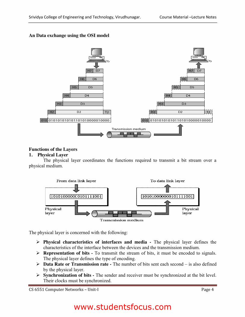
An Data exchange using the OSI model
Functions of the Layers 1. Physical Layer
The physical layer coordinates the functions required to transmit a bit stream over a physical medium.
The physical layer is concerned with the following:
¾ Physical characteristics of interfaces and media - The physical layer defines the characteristics of the interface between the devices and the transmission medium.
¾ Representation of bits - To transmit the stream of bits, it must be encoded to signals. The physical layer defines the type of encoding.
¾ Data Rate or Transmission rate - The number of bits sent each second – is also defined by the physical layer.
¾ Synchronization of bits - The sender and receiver must be synchronized at the bit level. Their clocks must be synchronized.
www.studentsfocus.com

Srividya College of Engineering and Technology, Virudhunagar. Course Material –Lecture Notes
CS 6551 Computer Networks – Unit-I Page 5
¾ Line Configuration - In a point-to-point configuration, two devices are connected together through a dedicated link. In a multipoint configuration, a link is shared between several devices.
¾ Physical Topology - The physical topology defines how devices are connected to make a network. Devices can be connected using a mesh, bus, star or ring topology.
¾ Transmission Mode - The physical layer also defines the direction of transmission between two devices: simplex, half-duplex or full-duplex.
2. Data Link Layer
It is responsible for transmitting frames from one node to next node.
The other responsibilities of this layer are
¾ Framing - Divides the stream of bits received into data units called frames. ¾ Physical addressing – If frames are to be distributed to different systems on the n/w ,
data link layer adds a header to the frame to define the sender and receiver. ¾ Flow control- If the rate at which the data are absorbed by the receiver is less than the
rate produced in the sender ,the Data link layer imposes a flow ctrl mechanism. ¾ Error control- Used for detecting and retransmitting damaged or lost frames and to
prevent duplication of frames. This is achieved through a trailer added at the end of the frame.
¾ Access control -Used to determine which device has control over the link at any given time.
3. NETWORK LAYER
This layer is responsible for the delivery of packets from source to destination.
I
www.studentsfocus.com

Srividya College of Engineering and Technology, Virudhunagar. Course Material –Lecture Notes
CS 6551 Computer Networks – Unit-I Page 6
t is mainly required, when it is necessary to send information from one network to another. The other responsibilities of this layer are ¾ Logical addressing - If a packet passes the n/w boundary, we need another addressing
system for source and destination called logical address. ¾ Routing – The devices which connects various networks called routers are responsible
for delivering packets to final destination.
4. TRANSPORT LAYER
¾ It is responsible for Process to Process delivery. ¾ It also ensures whether the message arrives in order or not.
The other responsibilities of this layer are ¾ ¾ ¾ ¾
¾ Port addressing - The header in this must therefore include a address called port address. This layer gets the entire message to the correct process on that computer.
¾ Segmentation and reassembly - The message is divided into segments and each segment is assigned a sequence number. These numbers are arranged correctly on the arrival side by this layer.
¾ Connection control - This can either be connectionless or connection-oriented. The connectionless treats each segment as a individual packet and delivers to the destination. The connection-oriented makes connection on the destination side before the delivery. After the delivery the termination will be terminated.
¾ Flow and error control - Similar to data link layer, but process to process take place.
www.studentsfocus.com
Srividya College of Engineering and Technology, Virudhunagar. Course Material –Lecture Notes
CS 6551 Computer Networks – Unit-I Page 7
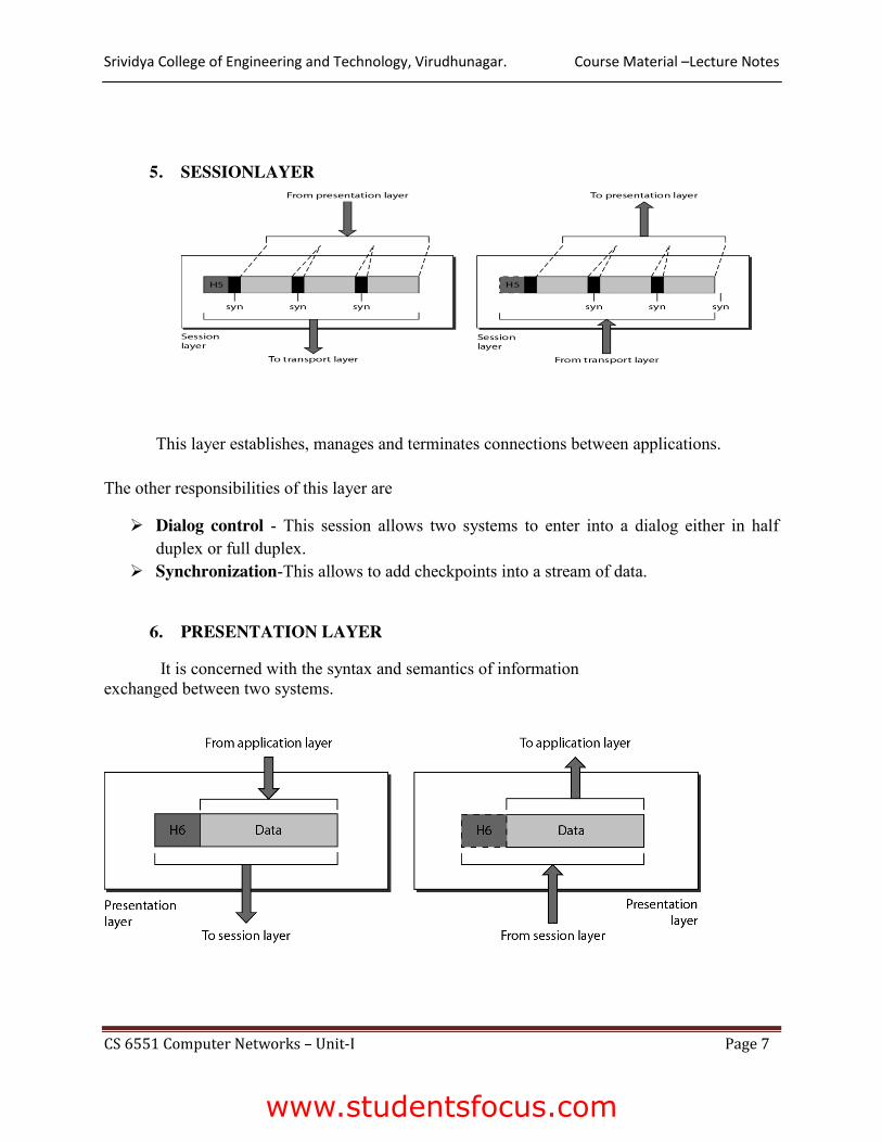
5. SESSIONLAYER
This layer establishes, manages and terminates connections between applications.
The other responsibilities of this layer are
¾ Dialog control - This session allows two systems to enter into a dialog either in half duplex or full duplex.
¾ Synchronization-This allows to add checkpoints into a stream of data.
6. PRESENTATION LAYER
It is concerned with the syntax and semantics of information exchanged between two systems.
www.studentsfocus.com

Srividya College of Engineering and Technology, Virudhunagar. Course Material –Lecture Notes
CS 6551 Computer Networks – Unit-I Page 8
The other responsibilities of this layer are
¾ Translation – Different computers use different encoding system, this layer is responsible for interoperability between these different encoding methods. It will change the message into some common format.
¾ Encryption and decryption-It means that sender transforms the original information to another form and sends the resulting message over the n/w. and vice versa.
¾ Compression and expansion-Compression reduces the number of bits contained in the information particularly in text, audio and video.
7. APPLICATION LAYER This layer enables the user to access the n/w. This allows the user to log on to remote
user.
The other responsibilities of this layer are
¾ FTAM(file transfer,access,mgmt) - Allows user to access files in a remote host.
¾ Mail services - Provides email forwarding and storage.
¾ Directory services - Provides database sources to access information about various
sources and objects.
www.studentsfocus.com

Srividya College of Engineering and Technology, Virudhunagar. Course Material –Lecture Notes
CS 6551 Computer Networks – Unit-I Page 9
The interaction between layers in the OSI model
www.studentsfocus.com

Srividya College of Engineering and Technology, Virudhunagar. Course Material –Lecture Notes
CS 6551 Computer Networks – Unit-I Page 10
Internet Architecture:
The Internet architecture, which is also sometimes called the TCP/IP architecture after its two main protocols, is depicted in Figure. An alternative representation is given in Figure. The Internet architecture evolved out of experiences with an earlier packet-switched network called the ARPANET. Both the Internet and the ARPANET were funded by the Advanced Research Projects Agency (ARPA), one of the research and development funding agencies of the U.S. Department of Defense. The Internet and ARPANET were around before the OSI architecture, and the experience gained from building them was a major influence on the OSI reference model.
Internet architecture is by definition a meta-network, a constantly changing collection of thousands of individual networks intercommunicating with a common protocol.
The Internet's architecture is described in its name, a short from of the compound word "inter-networking". This architecture is based in the very specification of the standard TCP/IP protocol, designed to connect any two networks which may be very different in internal hardware, software, and technical design. Once two networks are interconnected, communication with TCP/IP is enabled end-to-end, so that any node on the Internet has the near magical ability to communicate with any other no matter where they are. This openness of design has enabled the Internet architecture to grow to a global scale.
www.studentsfocus.com

Srividya College of Engineering and Technology, Virudhunagar. Course Material –Lecture Notes
CS 6551 Computer Networks – Unit-I Page 11
Network software:
Networking software, in the most basic sense, is software that facilitates, enhances or interacts with a computer network. One type of networking software allows computers to communicate with one another, while another type of networking software provides users access to shared programs. Networking software is a key component of today's computer networks, including the Internet. Understanding the types of networking software is the first step in understanding how your computer network really works. Performance:
Bandwidth and Latency Network performance is measured in two fundamental ways: bandwidth (also called throughput) and latency (also called delay). The bandwidth of a network is given by the number of bits that can be transmitted over the network in a certain period of time.
Bandwidth and throughput are two of the most confusing terms used in networking. While we could try to give you a precise definition of each term, it is important that you know how other people might use them and for you to be aware that they are often used interchangeably.
Latency = Propagation+Transmit+Queue Propagation = Distance/SpeedOfLight
Transmit = Size/Bandwidth
www.studentsfocus.com

Srividya College of Engineering and Technology, Virudhunagar. Course Material –Lecture Notes
CS 6551 Computer Networks – Unit-I Page 12
Category Metric Units
Productivity Throughput
Effective capacity Mbps
Responsiveness Delay
Round trip time Queue size
Milliseconds Packets
Utilization Channel utilization Percentage of time busy
Losses Packet loss rate Frame retries
Loss percentage
Buffer problems
AP queue overflow Playout buffer underflow
Packet drops Rebuffed events
Link layer Services:
Link layer Services:
The main task of the data link layer is that it transfers data from the network layer of one machine to the network layer of another machine. This is a part of the services it gives to the upper layer. If you remember, above the data link layer, we have the network layer. The data link layer gives a service to the network layer, and this service is the transfer of data from one network layer to the other, and this in turn uses the physical layer. It converts the raw bit stream of the physical layer into groups of bits or frames.
www.studentsfocus.com
Srividya College of Engineering and Technology, Virudhunagar. Course Material –Lecture Notes
CS 6551 Computer Networks – Unit-I Page 13
DLL offers unacknowledged connectionless and acknowledged connectionless services. In unacknowledged connectionless, there is no attempt to recover lost frame and there is no acknowledgement from the other side. I t is suited for low error rate networks or for fault tolerant applications such as voice. By voice tolerant application, we mean that even if some of the bits in a digitized voice stream drop, there will be some degradation on the other side. But to the human ear, it is imperceptible. That is why it is fault-tolerant. In acknowledged connectionless service, each frame is acknowledged by the receiver and it is suited for unreliable channels, where acknowledgement is required for special reliability. .
Acknowledged connection-oriented service ensures that all frames are received and each is received exactly once and these services are accomplished using simplex not the usual, but half-duplex or full-duplex channels.
These are some examples. It is a reliable message stream. It may be connection-oriented
service or connectionless service. It may be a reliable message stream (sequence of pages) or reliable byte stream (reliable login): in the latter it is coming byte by byte and in the former, it is page by page. An example of unreliable connection is digitized voice; unreliable datagram (electronic junk mail) is connectionless `service.
Framing:
To transmit frames over the node it is necessary to mention start and end of each frame. There are three techniques to solve this frame
¾ Byte-Oriented Protocols (BISYNC, PPP, DDCMP) ¾ Bit-Oriented Protocols (HDLC) ¾ Clock-Based Framing (SONET)
Byte Oriented protocols
In this, view each frame as a collection of bytes (characters) rather than a collection of bits. Such a byte-oriented approach is exemplified by the BISYNC (Binary Synchronous Communication) protocol and the DDCMP (Digital Data Communication Message Protocol)
Sentinel Approach
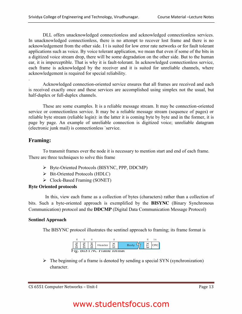
The BISYNC protocol illustrates the sentinel approach to framing; its frame format is
Fig: BISYNC Frame format
¾ The beginning of a frame is denoted by sending a special SYN (synchronization) character.
www.studentsfocus.com

Srividya College of Engineering and Technology, Virudhunagar. Course Material –Lecture Notes
CS 6551 Computer Networks – Unit-I Page 14
¾ The data portion of the frame is then contained between special sentinel characters: STX (start of text) and ETX (end of text).
¾ The SOH (start of header) field serves much the same purpose as the STX field. ¾ The frame format also includes a field labeled CRC (cyclic redundancy check) that is
used to detect transmission errors. The problem with the sentinel approach is that the ETX character might appear in the data portion of the frame. BISYNC overcomes this problem by ―escaping‖ the ETX character by preceding it with a DLE (data-link-escape) character whenever it appears in the body of a frame; the DLE character is also escaped (by preceding it with an extra DLE) in the frame body. This approach is called character stuffing.
Point-to-Point Protocol (PPP) The more recent Point-to-Point Protocol (PPP). The format of PPP frame is
Fig: PPP Frame Format
¾ The Flag field has 01111110 as starting sequence.
¾ The Address and Control fields usually contain default values
¾ The Protocol field is used for demultiplexing.
¾ The frame payload size can he negotiated, but it is 1500 bytes by default.
¾ The PPP frame format is unusual in that several of the field sizes are negotiated rather
than fixed.
¾ Negotiation is conducted by a protocol called LCP (Link Control Protocol).
¾ LCP sends control messages encapsulated in PPP frames—such messages are denoted by
an LCP identifier in the PPP Protocol.
Byte-Counting Approach
The number of bytes contained in a frame can he included as a field in the frame header.
DDCMP protocol is used for this approach. The frame format is
www.studentsfocus.com

Srividya College of Engineering and Technology, Virudhunagar. Course Material –Lecture Notes
CS 6551 Computer Networks – Unit-I Page 15
Fig: DDCMP frame format
¾ COUNT Field specifies how many bytes are contained in the frame’s body.
¾ Sometime count field will be corrupted during transmission, so the receiver will
accumulate as many bytes as the COUNT field indicates. This is sometimes called a
framing error.
¾ The receiver will then wait until it sees the next SYN character.
Bit-Oriented Protocols (HDLC)
In this, frames are viewed as collection of bits. High level data link protocol is used. The format is
Fig: HDLC Frame Format
¾ HDLC denotes both the beginning and the end of a frame with the distinguished bit
sequence 01111110.
¾ This sequence might appear anywhere in the body of the frame, it can be avoided by bit
stuffing.
¾ On the sending side, any time five consecutive 1’s have been transmitted from the body
of the message (i.e., excluding when the sender is trying to transmit the distinguished
01111110 sequence), the sender inserts a 0 before transmitting the next bit.
¾ On the receiving side, five consecutive 1’s arrived, the receiver makes its decision based
on the next bit it sees (i.e., the bit following the five is).
¾ If the next bit is a 0, it must have been stuffed, and so the receiver removes it. If the next
bit is a 1, then one of two things is true, either this is the end-of-frame marker or an error
has been introduced into the bit stream.
¾ By looking at the next bit, the receiver can distinguish between these two cases:
If it sees a 0 (i.e., the last eight bits it has looked at are 01111110), then it is the end-of-
frame marker.
www.studentsfocus.com

Srividya College of Engineering and Technology, Virudhunagar. Course Material –Lecture Notes
CS 6551 Computer Networks – Unit-I Page 16
If it sees a 1 (i.e., the last eight bits it has looked at are 01111111), then there must have
been an error and the whole frame is discarded.
Clock-Based Framing (SONET)
¾ Synchronous Optical Network Standard is used for long distance transmission of data
over optical network.
¾ It supports multiplexing of several low speed links into one high speed links.
¾ An STS-1 frame is used in this method.
¾ It is arranged as nine rows of 90 bytes each, and the first 3 bytes of each row are
overhead, with the rest being available for data.
¾ The first 2 bytes of the frame contain a special bit pattern, and it is these bytes that
enable the receiver to determine where the frame starts.
¾ The receiver looks for the special bit pattern consistently, once in every 810 bytes, since
each frame is 9 x 90 = 810 bytes long.
www.studentsfocus.com
Srividya College of Engineering and Technology, Virudhunagar. Course Material –Lecture Notes
CS 6551 Computer Networks – Unit-I Page 17
¾ The STS-N frame can he thought of as consisting of N STS-1 frames, where the bytes
from these frames are interleaved; that is, a byte from the first frame is transmitted, then a
byte from the second frame is transmitted, and so on.
¾ Payload from these STS-1 frames can he linked together to form a larger STS-N payload,
such a link is denoted STS-Nc. One of the bit in overhead is used for this purpose. Error Detection and Correction:
Data can be corrupted during transmission. For reliable communication, errors must be detected and corrected.
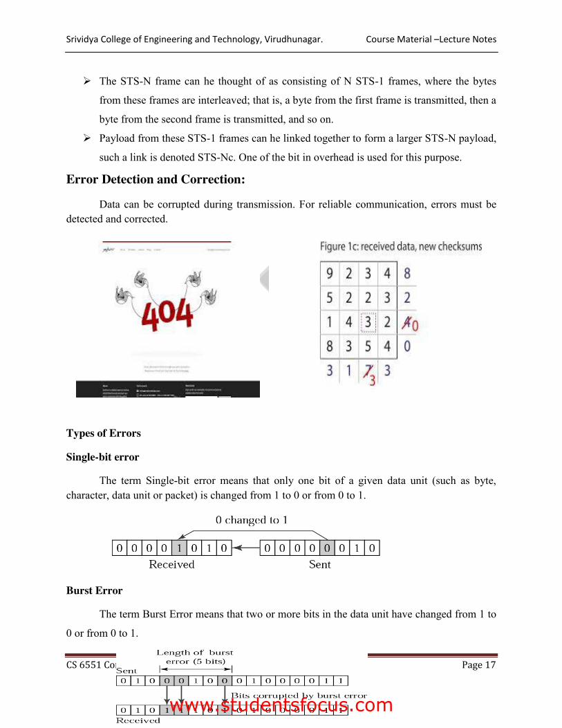
Types of Errors
Single-bit error
The term Single-bit error means that only one bit of a given data unit (such as byte, character, data unit or packet) is changed from 1 to 0 or from 0 to 1.
Burst Error
The term Burst Error means that two or more bits in the data unit have changed from 1 to
0 or from 0 to 1.
www.studentsfocus.com
Srividya College of Engineering and Technology, Virudhunagar. Course Material –Lecture Notes
CS 6551 Computer Networks – Unit-I Page 18
Redundancy
One method is to send every data twice, so that receiver checks every bit of two copies and detect error.
Drawbacks
¾ Sends n-redundant bits for n-bit message. ¾ Many errors are undetected if both the copies are corrupted.
Instead of adding entire data, some bits are appended to each unit.
This is called redundant bit because the bits added will not give any new information. These bits are called error detecting codes.
The three error detecting techniques are:
¾ Parity check ¾ Check sum algorithm
¾ Cyclic Redundancy Check
Parity Check
Simple parity check
Only one redundant bit, called parity bit is added to every data unit so that the total number of 1’s in unit become even (or odd)
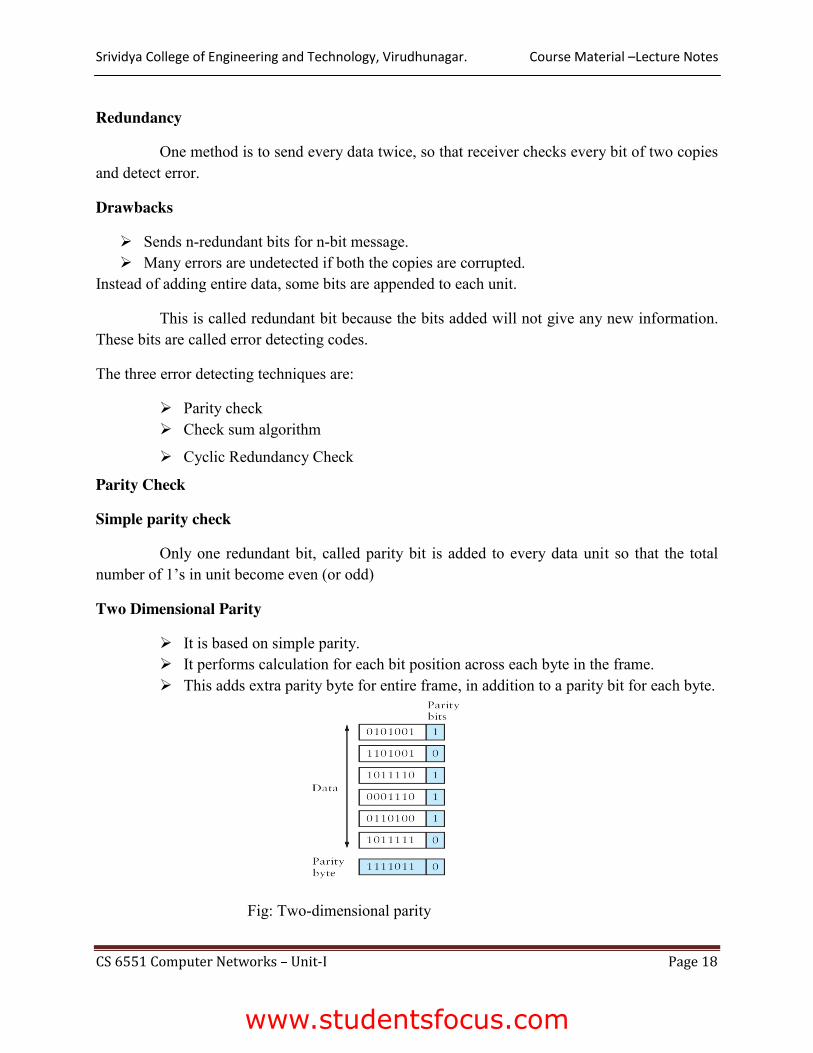
Two Dimensional Parity
¾ It is based on simple parity. ¾ It performs calculation for each bit position across each byte in the frame. ¾ This adds extra parity byte for entire frame, in addition to a parity bit for each byte.
Fig: Two-dimensional parity
www.studentsfocus.com
Srividya College of Engineering and Technology, Virudhunagar. Course Material –Lecture Notes
CS 6551 Computer Networks – Unit-I Page 19
For example frame containing 6 bytes of data. In this third bit of the parity byte is 1 since there are an odd number of 1’s is in the third bit across the 6 bytes in the frame.
In this case, 14 bits of redundant information are added with original information.
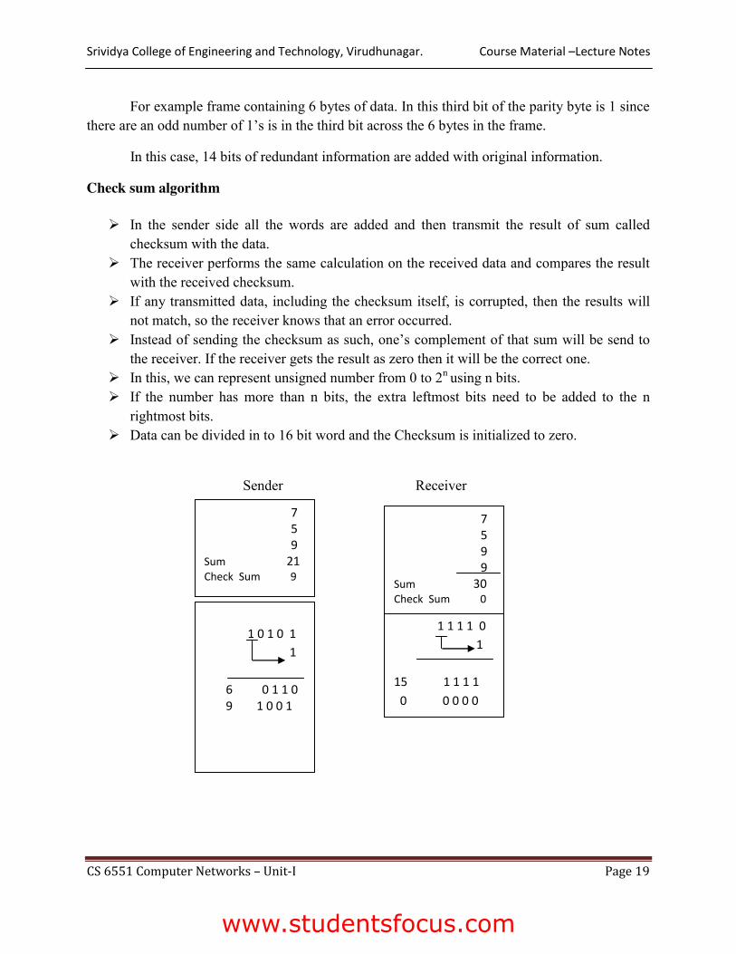
Check sum algorithm
¾ In the sender side all the words are added and then transmit the result of sum called checksum with the data.
¾ The receiver performs the same calculation on the received data and compares the result with the received checksum.
¾ If any transmitted data, including the checksum itself, is corrupted, then the results will not match, so the receiver knows that an error occurred.
¾ Instead of sending the checksum as such, one’s complement of that sum will be send to the receiver. If the receiver gets the result as zero then it will be the correct one.
¾ In this, we can represent unsigned number from 0 to 2n using n bits. ¾ If the number has more than n bits, the extra leftmost bits need to be added to the n
rightmost bits. ¾ Data can be divided in to 16 bit word and the Checksum is initialized to zero.
Sender Receiver
7 5 9
Sum 21 Check Sum 9
1 0 1 0 1
1
6 0 1 1 0 9 1 0 0 1
1 1 1 1 0
1
15 1 1 1 1
0 0 0 0 0
7 5 9 9
Sum 30 Check Sum 0
www.studentsfocus.com

Srividya College of Engineering and Technology, Virudhunagar. Course Material –Lecture Notes
CS 6551 Computer Networks – Unit-I Page 20
Cyclic Redundancy Check
¾ It uses small number of redundant bits to detect errors. ¾ Divisor is calculated by the polynomial functions under two conditions
a. It should not be divisible by x b. It should be divisible by x+1
8 Consider the original message as M(x) – n+1 bits 9 Divisor C(x) – K bits 10 Original sent message = M(x) + k-1 bits
Steps
¾ Append k-1 zeros with M(x) – P(x) ¾ Divide P(x) by C(x) ¾ Subtract the remainder from T(x) ¾ Subtraction is made by making XOR operation
Eg: 100100 by 1101
www.studentsfocus.com

Srividya College of Engineering and Technology, Virudhunagar. Course Material –Lecture Notes
CS 6551 Computer Networks – Unit-I Page 21
Error Correction
Error Correction can be handled in two ways
1. When an error is discovered, the receiver can have the sender to retransmit the entire data unit.
2. A receiver can use an error correcting code, which automatically correct certain errors. Error correcting codes are more sophisticated than error-detection codes and require more redundancy bits.
In single bit error detection only two states are sufficient.
1) error
2) no error
Two states are not enough to detect an error but not to correct it.
Redundancy Bits
¾ To calculate the number of redundancy bit(r) required to correct a given number of data bits (m), we must find a relationship between m and r.
¾ Add m bits of data with r bits. The length of the resulting code is m+r. Data and Redundancy bits
¾ If the total number of bits are m+r, then r must be able to indicate at least m+r+1 different states. r bits can indicate 2r different states. Therefore, 2r must be equal to or greater than m+r+1
2r >=m+r+1
www.studentsfocus.com

Srividya College of Engineering and Technology, Virudhunagar. Course Material –Lecture Notes
CS 6551 Computer Networks – Unit-I Page 22
Relationship between data and redundancy bits
Number of Data Bits (m)
Number of redundancy Bits(r)
Total bits (m+r)
1
2 3 2
3 5 3
3 6 4
3 7 5
4 9 6
4 10 7
4 11 Hamming Code
R.W. Hamming provides a practical solution for the error correction.
Positioning the Redundancy Bits
For example, a seven-bit ASCII code requires four redundancy bits that can be added to the end of the data or intersperse with the original data bits. These redundancy bits are placed in positions 1, 2, 4 and 8. We refer these bits as r1, r2, r3 and r4
Position of redundancy bits in Hamming code
The combination used to calculate each of the four r values for a seven-bit data sequence are as follows
¾ The r1 bit is calculated using all bits positions whose binary representation include a 1 in the rightmost position
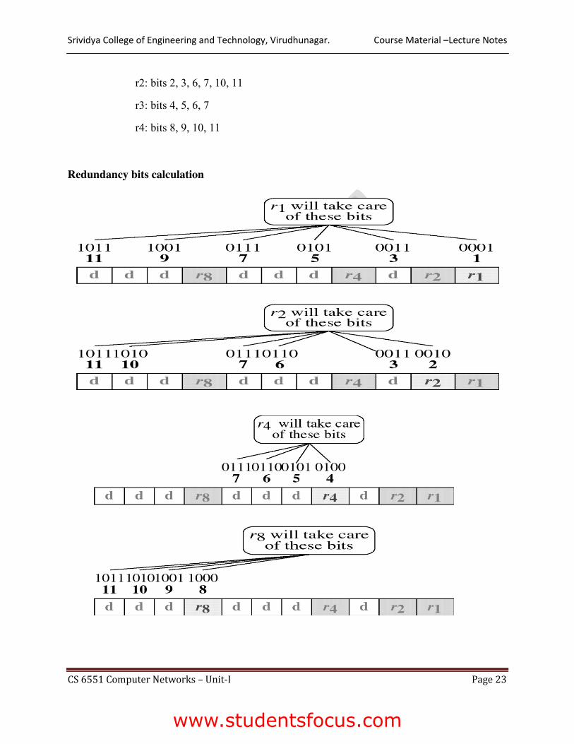
¾ r2 is calculated using all bit position with a 1 in the second position and so on r1: bits 1,3,5,7,9,11
www.studentsfocus.com
Srividya College of Engineering and Technology, Virudhunagar. Course Material –Lecture Notes
CS 6551 Computer Networks – Unit-I Page 23
r2: bits 2, 3, 6, 7, 10, 11
r3: bits 4, 5, 6, 7
r4: bits 8, 9, 10, 11
Redundancy bits calculation
www.studentsfocus.com

Srividya College of Engineering and Technology, Virudhunagar. Course Material –Lecture Notes
CS 6551 Computer Networks – Unit-I Page 24
Calculating the r values
¾ Place each bit of the original character in its appropriate position in the 11-bit unit.
¾ Calculate the even parities for the various bit combination.
¾ The parity value for each combination is the value of the corresponding r bit.
For example,
¾ The value of r1 is calculated to provide even parity for a combination of bits 3,5,7,9
and 11.
¾ The value of r2 is calculated to provide even parity with bits 3, 6, 7, 10 and 11.
¾ The value of r3 is calculated to provide even parity with bits 4,5,6 and 7.
¾ The value of r4 is calculated to provide even parity with bits 8,9,10 and 11.
Error Detection and Correction
Now imagine the received data has 7th bit changed from 1 to 0.
Single-bit error
www.studentsfocus.com

Srividya College of Engineering and Technology, Virudhunagar. Course Material –Lecture Notes
CS 6551 Computer Networks – Unit-I Page 25
The receiver takes the transmission and recalculates four new data using the same set of bits
used by the sender plus the relevant parity (r) bit for each set.
Error detection
¾ Then it assembles the new parity values into a binary number in order of r position
(r8,r4,r2,r1).
¾ This step gives us the binary number 0111(7 in decimal) which is the precise location of
the bit in error.
¾ Once the bit is identified, the receiver can reverse its value and correct the error.
Hamming Distance
One of the central concepts in coding for error control is the idea of the Hamming distance.
¾ The Hamming distance between two words (of the same size) is the number of differences between the corresponding bits. The Hamming distance between two words x and y is d(x, y).
www.studentsfocus.com
Course Material –Lecture Notes
CS 6551 Computer Networks – Unit-I Page 26
¾ The Hamming distance can be found by applying the XOR operation on the two words and count the number of 1’s in the result.
¾ In a set of words, the minimum Hamming distance is the smallest Hamming distance between all possible pairs. We use dmin to define the minimum Hamming distance in a coding scheme.
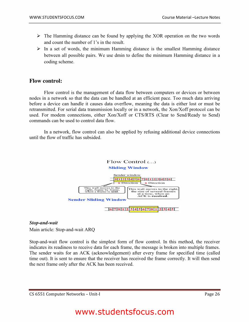
Flow control:
Flow control is the management of data flow between computers or devices or between nodes in a network so that the data can be handled at an efficient pace. Too much data arriving before a device can handle it causes data overflow, meaning the data is either lost or must be retransmitted. For serial data transmission locally or in a network, the Xon/Xoff protocol can be used. For modem connections, either Xon/Xoff or CTS/RTS (Clear to Send/Ready to Send) commands can be used to control data flow.
In a network, flow control can also be applied by refusing additional device connections until the flow of traffic has subsided.
Stop-and-wait Main article: Stop-and-wait ARQ
Stop-and-wait flow control is the simplest form of flow control. In this method, the receiver indicates its readiness to receive data for each frame, the message is broken into multiple frames. The sender waits for an ACK (acknowledgement) after every frame for specified time (called time out). It is sent to ensure that the receiver has received the frame correctly. It will then send the next frame only after the ACK has been received.
WWW.STUDENTSFOCUS.COM
www.studentsfocus.com
Course Material –Lecture Notes
CS 6551 Computer Networks – Unit-I Page 27
Operations
1. Sender: Transmits a single frame at a time(TTL). 2. Receiver: Transmits acknowledgement (ACK) as it receives a frame. 3. Sender and receiver ACK within time out. 4. Go to step 1.
If a frame or ACK is lost during transmission then it has to be transmitted again by sender. This retransmission process is known as ARQ (automatic repeat request).
The problem with Stop-and wait is that only one frame can be transmitted at a time, and that often leads to inefficient transmission, because until the sender receives the ACK it cannot transmit any new packet. During this time both the sender and the channel are unutilized.
Flow control is the mechanism that ensures the rate at which a sender is transmitting is in proportion with the receiver’s receiving capabilities. Flow control is utilized in data communications to manage the flow of data/packets among two different nodes, especially in cases where the sending device can send data much faster than the receiver can digest.
WWW.STUDENTSFOCUS.COM
www.studentsfocus.com
Related Documents