Computer Modeling of Modern Antenna Arrays Marinos N. Vouvakis

Welcome message from author
This document is posted to help you gain knowledge. Please leave a comment to let me know what you think about it! Share it to your friends and learn new things together.
Transcript
Computer Modeling of Modern Antenna ArraysMarinos N. Vouvakis
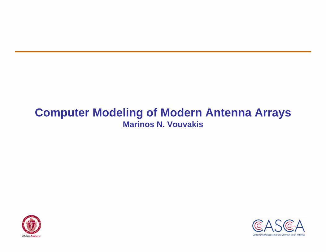
Obtain Transfer Fn of Building Block (FETI)
Problem Partitioning in Domains*
Adaptive Mesh Refinement on
Building Blocks
Construct Domains
Using Building Blocks*
Connect Domains using “cement”
technique & Outer Loop DDM Iteration
Extract Engineering Info. Antenna Pattern, Impedance,
Q Factors, etc
Recover Fields from Reduced Surface Unknowns for Each
Domain
*Domain is a translation invariant instance of a Building
Block.
Analysis OverviewHigher Order FEM–Tree-Cotree–pMUS–hAMR–DD–Cement–FETI
x
y
zθ=30º
φ=90º
d=7.9λ
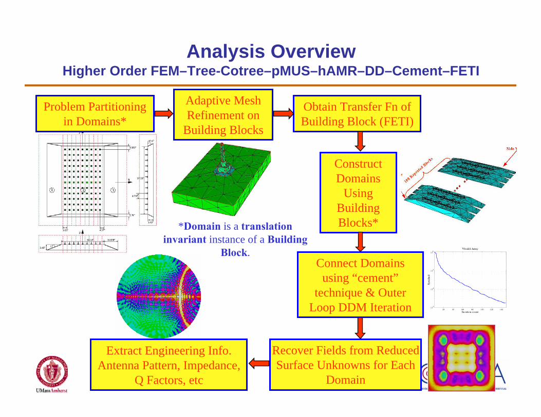
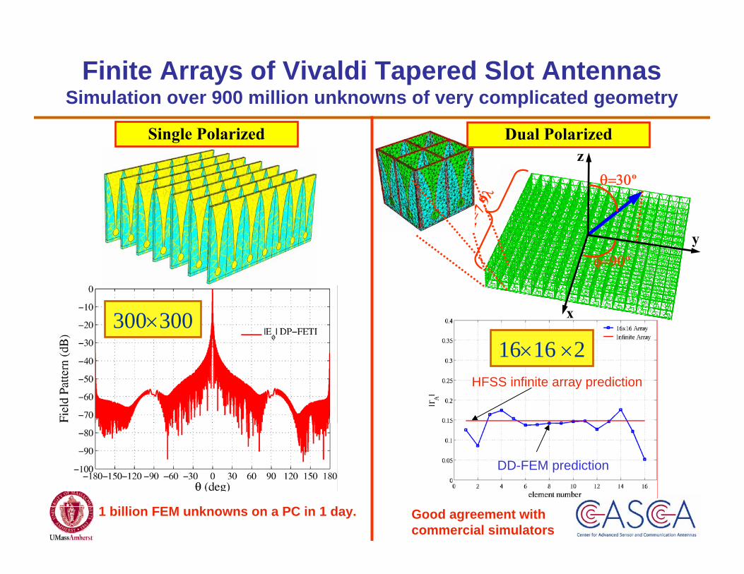
300×300
Single Polarized
16×16 ×2
Finite Arrays of Vivaldi Tapered Slot AntennasSimulation over 900 million unknowns of very complicated geometry
HFSS infinite array prediction
DD-FEM prediction
1 billion FEM unknowns on a PC in 1 day.
Dual Polarized
Good agreement with commercial simulators

Scan
dire
ctio
n
G0=23.31dBi (Simulated)G0=23.44dBi (Measured)
Scan dirzection
24×12 RADAR Sub-array ModuleDomain Decomposition FEM vs. Measurements
Good agreement with measurements (impedance too)
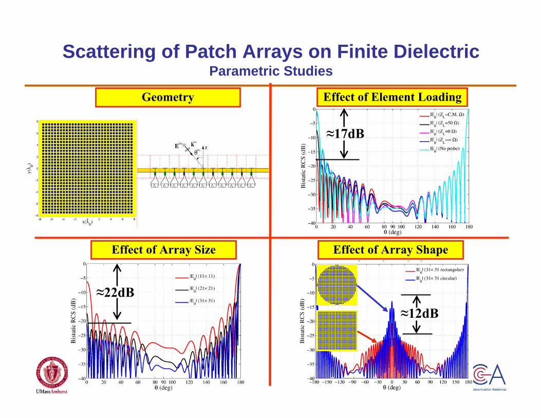
≈17dB
Scattering of Patch Arrays on Finite DielectricParametric Studies
≈22dB≈12dB
Geometry
Effect of Array Size Effect of Array Shape
Effect of Element Loading

0° scan
x
y
z
Active Reflection Coeff.Near & Far Fields
x
y
z
Finite Patch Arrays on Truncated CylindersDD-FEM for Curved Structures (Rotational Symmetry)
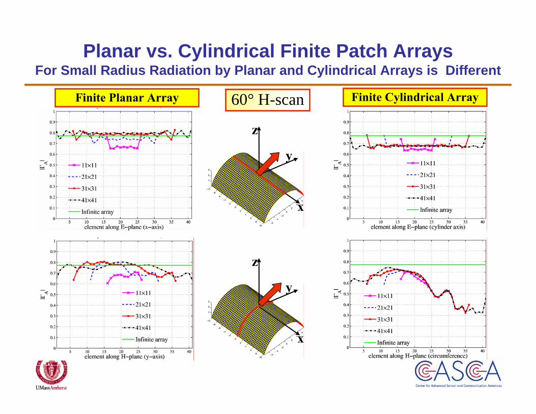
60° H-scan
x
y
z
x
y
z
Planar vs. Cylindrical Finite Patch ArraysFor Small Radius Radiation by Planar and Cylindrical Arrays is Different
Finite Planar Array Finite Cylindrical Array

xy
xz
(TTVG-800)
(TTVG-800)
Active Reflection Coeff.
Near & Far Fields
Magnitude Phase
Geometry.
Finite Arrays of Ferrite Loaded CBS ArraysDD-FEM for anisotropic non-reciprocal materials
Arrays involving complex material simulated in PCs within few hours

−15
−10
−5
0
5
10
0
30
60
90
120
150
180180
150
120
90
60
30
Top View —1.5λ away
Back View —1.5λ away
PEC
Ground Plane
AM
C G
roun
d Pl
ane
Back View —1.5λ away
Top View —1.5λ away
PEC Ground PlaneAMC Ground Plane
Monopole Radiation over EBGSimulation of 39 million unknowns

Teflon Lens
Split Ring LensNegative Refraction Lens
Geometry (Top View)
Metamaterial Plano-concave Lens3D simulation of 50 million unknowns, Very challenging geometry
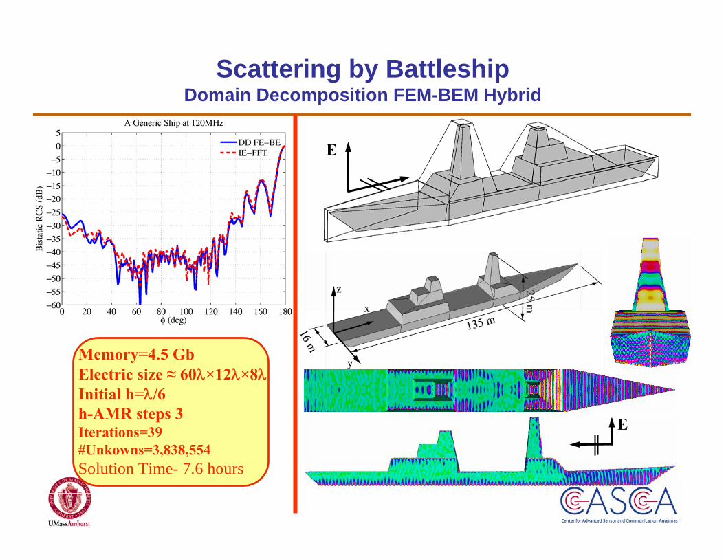
Memory=4.5 GbElectric size ≈ 60λ×12λ×8λInitial h=λ/6h-AMR steps 3Iterations=39#Unkowns=3,838,554Solution Time- 7.6 hours
E
E
Scattering by BattleshipDomain Decomposition FEM-BEM Hybrid
Related Documents