Computer Communications Sunggu Lee EE Dept., POSTECH Sep. 7, 2006

Computer Communications Sunggu Lee EE Dept., POSTECH Sep. 7, 2006.
Jan 02, 2016
Welcome message from author
This document is posted to help you gain knowledge. Please leave a comment to let me know what you think about it! Share it to your friends and learn new things together.
Transcript
ComputerCommunications
Sunggu LeeEE Dept., POSTECHSep. 7, 2006
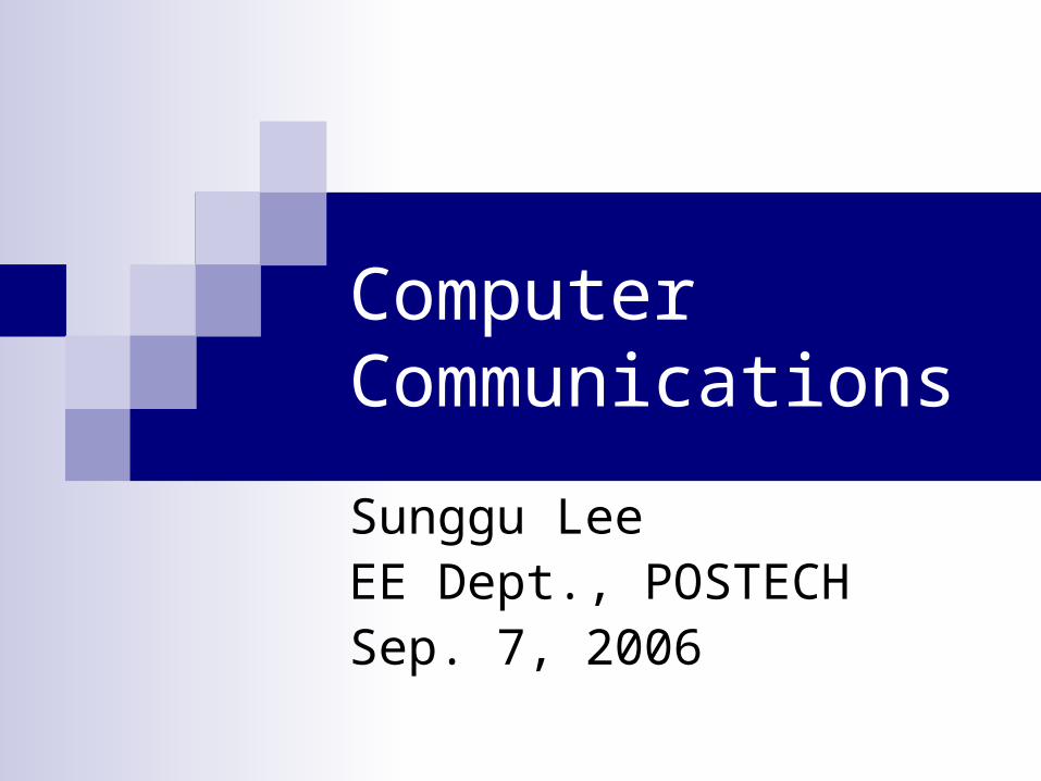
Analog and Digital Signals
Analog: real-world signal
Digital: “digitized” version of original analog signal - represented as sequence of binary bits - e.g., 12, 7, 7, 6, 10, 14, 15, 15, … 11000111011101101010111011111111…

Digital Signal Representation Bit Representation (Logic 0 and 1) in Wireless Communication
Channel Typically based on electromagnetic (EM) waves
Changes in electrical current flow cause EM waves Example methods
Sine wave frequencies: high frequency = 1, low frequency = 0 Sine wave phases: 0 degree = 1, 90 degree = 0
Bit Representation (Logic 0 and 1) in Wired Communication Channel Optical: no light = 0, light = 1 Current: no current = 0, positive current = 1 Voltage
Positive logic: 0 = low voltage, 1 = high voltage Noise margins, voltage ranges used to permit small variations in input &
output voltage values LSTTL: for inputs, ‘0’ = 0.0-0.8V and ‘1’ = 2.0-5.0V
for outputs, ‘0’ = 0.0-0.5V and ‘1’ = 2.7-5.0V
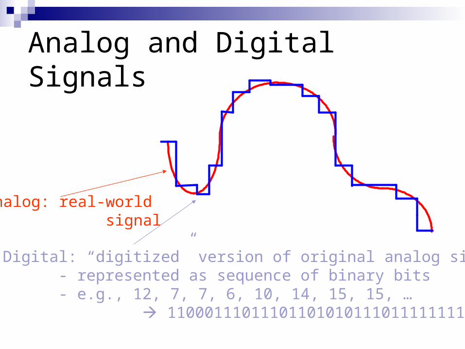
Wireless Communication
Communication “medium” (thing through which the data is communicated) is shared Each “communication connection” is referred to as a
“channel” Methods for sharing the communication medium
Time division multiple access (TDMA) Frequency division multiple access (FDMA) Code division multiple access (CDMA)
Many different varieties Example: use a frequency hopping code
Change communication frequencies in a predetermined pattern
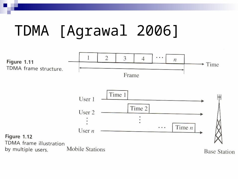
TDMA [Agrawal 2006]
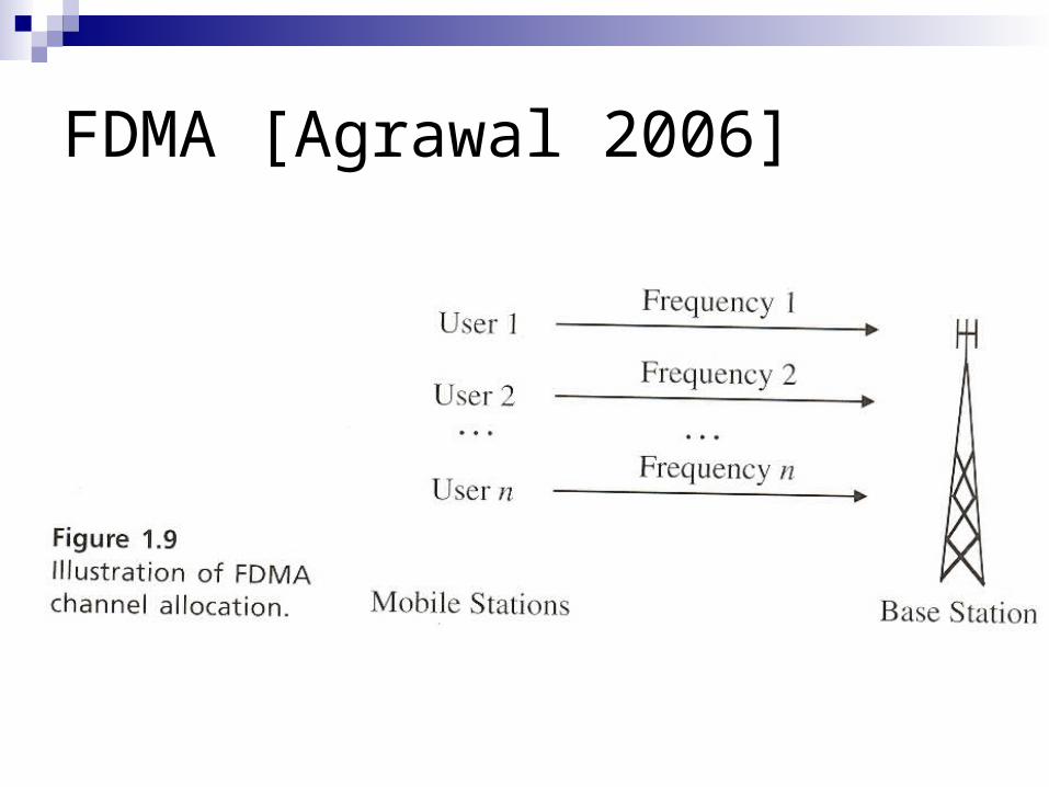
FDMA [Agrawal 2006]

CDMA [Agrawal 2006]
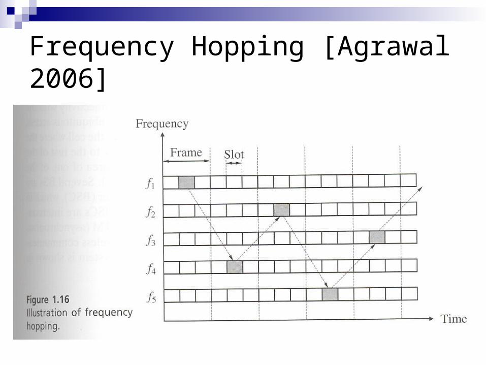
Frequency Hopping [Agrawal 2006]
Binary Codes
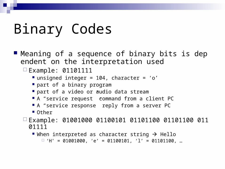
Meaning of a sequence of binary bits is dependent on the interpretation used Example: 01101111
unsigned integer = 104, character = ‘o’ part of a binary program part of a video or audio data stream A “service request” command from a client PC A “service response” reply from a server PC Other
Example: 01001000 01100101 01101100 01101100 01101111
When interpreted as character string Hello ‘H’ = 01001000, ‘e’ = 01100101, ‘l’ = 01101100, …
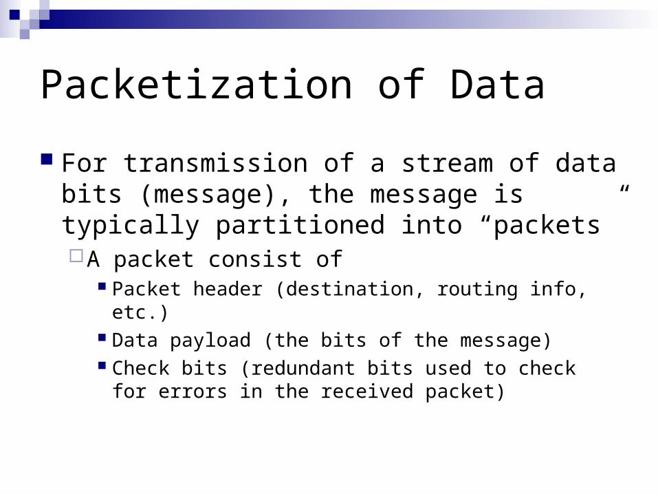
Packetization of Data
For transmission of a stream of data bits (message), the message is typically partitioned into “packets”A packet consist of
Packet header (destination, routing info, etc.) Data payload (the bits of the message) Check bits (redundant bits used to check for
errors in the received packet)

Communication Protocols
For successful transmission/receipt of a packet, the transmitter and receiver must agree on a “communication protocol” Set of rules on how the packet is interpreted
How to sample the bits of the packet Signaling method Synchronization of the transmitter/receiver
How to determine which parts of the packet are the packet header (destination info, etc.), data payload, check bits, etc.
How to interpret the bits of the data payload Integer, floating-point, character string, JPEG picture,
etc.
Computer Communication Models and Communication Protocol Suites Most commonly used reference base
communication model is the Open Systems Interconnection (OSI) model Standardized by the International Organization
for Standardization (ISO) Most common implementation of the OSI
model is a set of protocols referred to as the TCP/IP protocol suite (or stack) TCP = Transmission Control Protocol IP = Internet Protocol

Communication Protocols
ApplicationApplication
PresentationPresentation
SessionSession
TransportT ransport
NetworkNetwork
Data LinkData Link
PhysicalPhysical
Protocol forUnderlyingNetwork
Protocol forUnderlyingNetwork
OSI Model TCP/IP Protocol Suite
TCP UDP
SMTP FTPTELNET
DNS SNMP NFS HTTP
RPC
InternetProtocol(IP)
InternetProtocol(IP)
IPICMP IGMP
RARPARP
Ethernet ATMTokenRing . . .
L1
L2
L3
L4
L5
L7
L6
[Forouzan 2003]
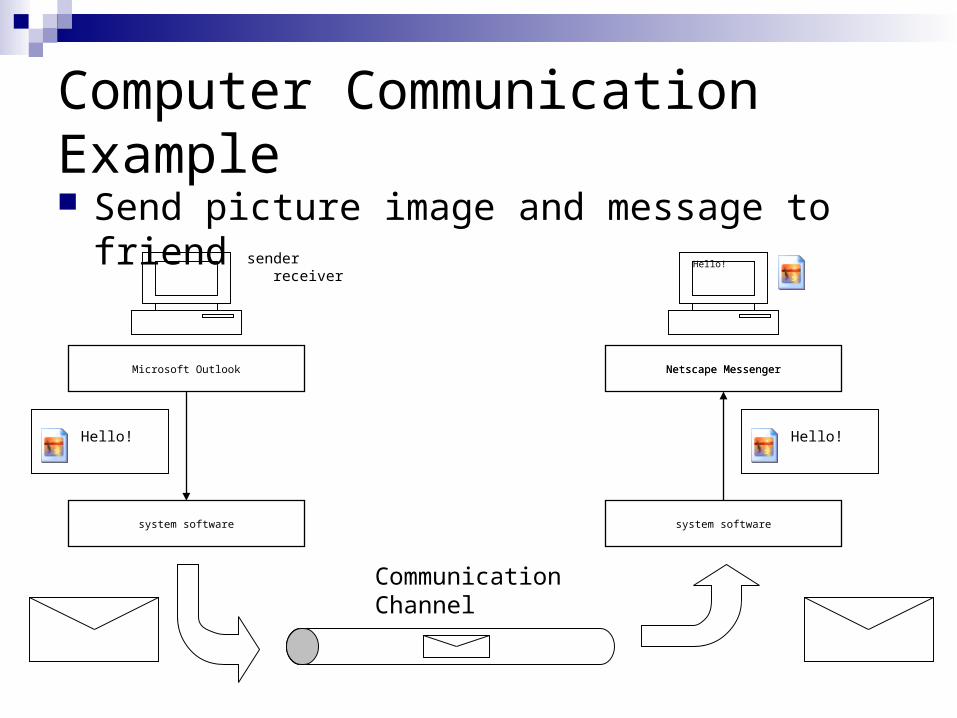
Computer Communication Example Send picture image and message to friend
Microsoft Outlook
system software
Hello!
Netscape Messenger
system software
Hello!
Hello!
Netscape Messenger
sender receiver
CommunicationChannel
001100110000111100001111000
sender
Hello!Hello!
Encoded Data
MS Outlook
Data1H4 Data2H4 Data3H4
Data1H3 OtherH3 Data2H3
Data11H2 OtherH2 Data12H2
receiver
L7throughL5
L4
L3
L2
L1 001100110000111100001111000
Hello!Hello!
Encoded Data
Netscape
Data1H4 Data2H4 Data3H4
Data1H3 OtherH3 Data2H3
Data11H2 OtherH2 Data12H2
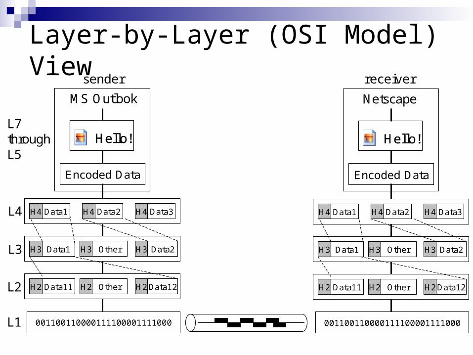
Layer-by-Layer (OSI Model) View
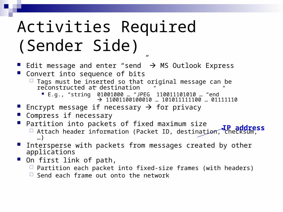
Activities Required (Sender Side) Edit message and enter “send” MS Outlook Express Convert into sequence of bits
Tags must be inserted so that original message can be reconstructed at destination
E.g., “string” 01001000 … “JPEG” 110011101010 … “end” 11001100100010 … 101011111100 … 01111110
Encrypt message if necessary for privacy Compress if necessary Partition into packets of fixed maximum size
Attach header information (Packet ID, destination, checksum, …) Intersperse with packets from messages created by other
applications On first link of path,
Partition each packet into fixed-size frames (with headers) Send each frame out onto the network
IP address
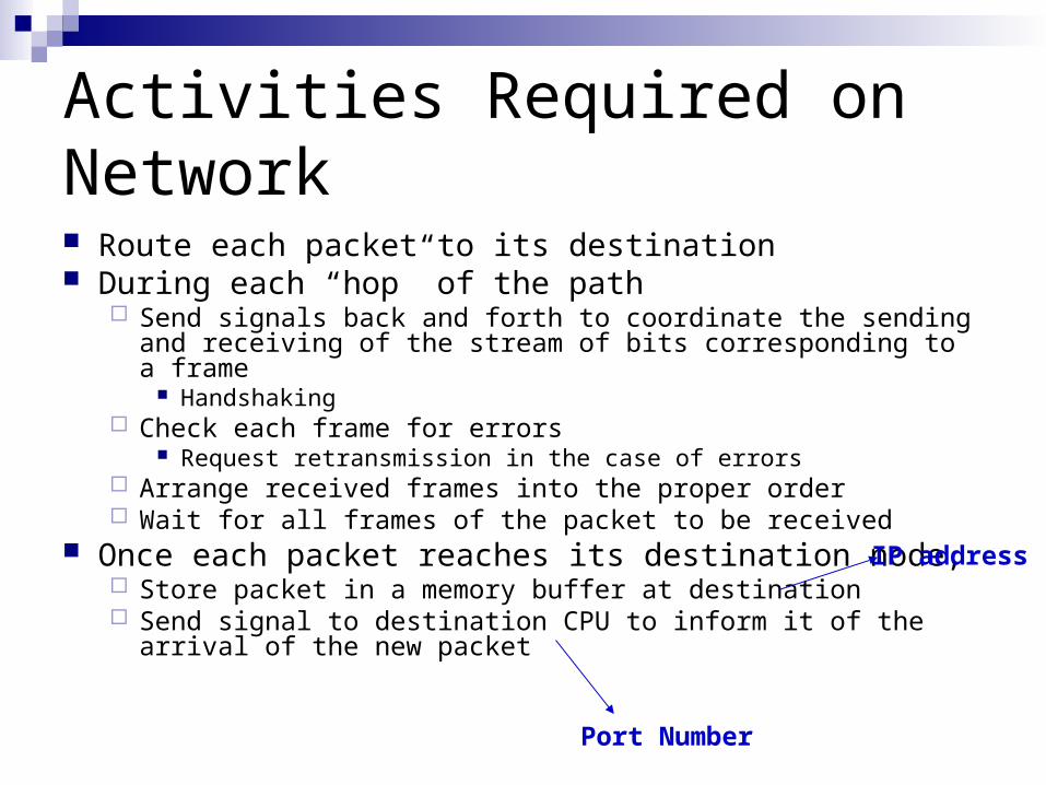
Activities Required on Network Route each packet to its destination During each “hop” of the path
Send signals back and forth to coordinate the sending and receiving of the stream of bits corresponding to a frame
Handshaking Check each frame for errors
Request retransmission in the case of errors Arrange received frames into the proper order Wait for all frames of the packet to be received
Once each packet reaches its destination node, Store packet in a memory buffer at destination Send signal to destination CPU to inform it of the arrival of
the new packet
Port Number
IP address
Activities at Destination Node Receive packets
Check each packet for errors and request retransmission in the case of errors
Arrange received packets into the proper order Once all packets have been received, form a complete
message Decompress if necessary Decrypt if necessary Check for errors Use tags in the bit stream to reconstruct the
message Show message to user using email tool (e.g., MS
Outlook Express)

Network Addresses IP (Internet Protocol) address
Address used to identify a computing node on the internet Network layer (L3) address E.g., 141.223.165.189 (Look up “properties” on “TCP/IP” on “Network”)
MAC (Medium Access Control) address Address used to identify a LAN card – cannot be changed Data link layer (L2) address E.g., abcd1234 (Enter “ipconfig /all” from MS Windows “cmd” window)
Port address Address used to identify a network interface point for an application prog. Corresponds to a memory buffer
Send a message - write to a memory buffer on a remote computer Receive a message – read from a memory buffer on the local computer
Example: 39 (for FTP), 3000 (for a user-defined port)

Connection-Oriented and Connectionless Networking Connection-oriented networking
Uses a specific network path that is established for the duration of a connection
Three phases: connection establishment, data transfer, connection termination
Main advantage: reliable communication Main implementation method: TCP (transfer control protocol)
Connectionless networking Finds a new path for each packet sent Main advantage: fast communication for short messages Main implementation method: UDP (user datagram protocol)
Communication Performance Parameters (1) Throughput ( 데이터 처리량 )
Actual number of bits transmitted per second Note 1: different from latency ( 지연시간 ) Note 2: different from bandwidth ( 대역폭 )
Most important communication performance parameter
Typical measurement method Send a data file from a source node to a destination node
Record the time t1 when the first byte of the data is received
Record the time t2 when the last byte of the data is received Divide amount of data received by (t2 – t1)
Note: Mbps = mega-bits-per-second (not bytes)

Communication Performance Parameters (2) Bandwidth
Maximum number of bits that can be transmitted per second
Note 1: different from latency ( 지연 시간 ) Note 2: different from throughput ( 데이터 처리량 )
Measures performance of network only (not the computer hardware or software)
Typical measurement method Difficult to measure since effects of small data amounts,
software and hardware at source and destination nodes must be removed
The “rated” figure stated in the specifications for the relevant communication protocol is most commonly used
E.g., 11 Mbps for IEEE 802.11b

Communication Performance Parameters (3) Latency
Time required for the first byte of a message to be transferred from the source to the destination node
Should include software processing time Typical measurement method
At time t1, source node sends a very small message to destination node
Destination node receives message and sends it back to the source node
Source node receives message and records the time t2 One-way communication latency is (t2 – t1) / 2 Why can’t we measure latency directly (record time t3 at
destination and measure latency as t3 – t1)?
Communication Performance Parameters (4) Other parameters also sometimes
measuredExample: Packet loss rate
Number of packets dropped by the network Most relevant to wireless networks
References
Behrouz A. Forouzan, TCP/IP Protocol Suite, 2nd Ed., McGraw-Hill, Boston, 2003.
D. P. Agrawal and Q.-A. Zeng, Introduction to Wireless and Mobile Systems, 2nd Ed., Nelson, Toronto, 2006.
Related Documents