The 14th IFToMM World Congress, Taipei, Taiwan, October 25-30, 2015 DOI Number: 10.6567/IFToMM.14TH.WC.OS6.013 Computer-Aided Kinematic Error Analysis of a Two-Stage Cycloidal Drive Wei-Pu Kao 1 Chang-Chia Hsieh 2 Jyh-Jone Lee 1 1 Department of Mechanical Engineering 2 Mechanical and Systems Research Lab National Taiwan University Industrial Technology Research Institute Taipei, Taiwan Hsin-Chu, Taiwan Abstract— The cycloidal drive is a high-efficiency, high-ratio, and low-backlash speed reduction device. It has been commonly used for transmitting motion and torque in machinery. This paper presents the computer-aided kinematic error analysis for a two-stage cycloidal gear drive such that the design parameters of the device can be evaluated according to the error analysis. In this work, the mathematic model for the gearing analysis will be established, especially for the tooth contact analysis with teeth modifications due to manufacturing error. A computer interface for the kinematic error analysis is also developed such that the result can be promptly obtained if various design parameters are assigned. Keywords: Two-Stage Cycloidal Gear Reducer, Tooth Modification, Tooth Contact Analysis, Kinematic Error. I. Introduction Cycloidal drives (or cycloidal gear reducers) are high-efficiency and high speed reduction ratio motion and torque transmission devices. They are commonly used in equipment where precise output and large drive payloads are needed. Recently, with the increasing demand of high efficiency and high speed reduction and torque ratio transmission devices in industry, applications of cycloidal drives have become popular in the automation field as robotics, machine tools, and automatic machinery. Nonetheless, compared to involute gear drives, fabricating cycloidal gear reducers requires more dedicated process because of the non-standard characteristics of the devices. Further, tools for manufacturing cycloidal gears are not as specialized as for manufacturing involute gears. These features make accuracy control and cost reduction of manufacturing cycloidal drives a great challenging task. The research and development of the cycloidal gear reducers have been investigated by many researchers, including profile generation [1-6], conditions for non-undercutting manufacturing [7-9], manufacturing errors and their influence on output speed [10, 11], force analysis and efficiency [12, 13], and development of new mechanisms [14-18]. The early literature that studied cycloidal drives can be dated back to Botsiber and Kingston [1] and Pollitt [2] where the cycloid speed reducer was initially introduced. Then, papers of cycloidal drives deal with the geometry and profile generation of the cycloidal disc. Other research considers profiles generated from different types of tooth [5]. Blanche and Yang [3] used vector method to generate the cycloidal profile while Yan and Lai [4] approached the problem by means of the theory of conjugate surfaces. Hsieh [6] studied the epitrochoidal and hypotrochoidal profiles by the theory of gearing thoroughly. Fong and Tsay [7] and Hsieh and Hwang [8] derived the conditions for non-undercutting and obtained the constraint of parameters for non-undercutting. Sensinger [9] presented a unified approach to cycloidal drive profile, stress and efficiency with closed-form equations. Blance and Yang [10] investigated machining tolerances of cycloidal drives and their influence on output speed by means of instant centers. Huang [11] also studied the profile modification and tooth contact analysis of the cycloidal drive. On the other hand, the development of new cycloidal drives can also be found in patent literature [14, 15]. Li, et al. [16] proposed a new drive for high load capacity. Blagojevic et al. [17] introduced a new two-stage cycloidal speed reducer of which speed reduction ratio was increased compared with the one-stage cycloidal drive. Lin et al. [18] also proposed a few new two-stage cycloidal speed reducers from the viewpoint of topological analysis. In the paper, the kinematic error analysis of the two-stage cycloidal drive is illustrated with a specific design example. To enhance the design of the two-stage cycloidal drive, the analysis of the kinematic errors due to various design parameters and indeed in need. Thus, the aim of this work is to address the development of a computer-aided program for the kinematic analysis for the two-stage cycloidal gear reducer. The cycloidal gear reducer from the topological view point is first reviewed such that the structural characteristics can be further realized. Then, the kinematics of the two-stage cycloidal gear drive with tooth modifications is performed by the theory of gearing [19]. The profile tolerances that compensate the errors of assembly and manufacturing will also be derived. The kinematic errors caused by the tooth modifications are conducted via tooth contact analysis. Finally, a computer-aided program that gives the result of kinematic error analysis is developed. II. Structure of the Cycloid Drive A. Structure of the Cycloid Drive The schematic of the two-stage cycloidal gear drive proposed by [18] is shown in Fig. 1(a). The first-stage of the drive consists of Case 1 (acted as fixed frame), the eccentric crank 2 and the first-stage cycloid disc 3. The eccentric crank 2 rotates and deflects the first-stage cycloidal disc 2 such that the cycloidal disc 2 orbits and wobbles about the center of the crank shaft because of the crank’s eccentricity and meshing between the disc and rollers on the case. The wobbling motion of the cycloidal disc 3 is then transmitted to the second-stage cycloidal disc 3’ through the pin-in-hole structure such that the rotational speeds of two cycloidal discs are identical. The two cycloidal discs 3 and 3' are designed of equal mass and then placed at an identical radius (eccentricity), 180° apart rotationally on the crank shaft 2. Finally, an output ring 4 is made to mesh with the cycloidal disc 3' via cycloidal gear pair and serves as the output link. Consequently, the kinematic schematic can be depicted as shown in Fig. 1(a) and the corresponding graph representation is shown in Fig.

Welcome message from author
This document is posted to help you gain knowledge. Please leave a comment to let me know what you think about it! Share it to your friends and learn new things together.
Transcript
The 14th IFToMM World Congress, Taipei, Taiwan, October 25-30, 2015 DOI Number: 10.6567/IFToMM.14TH.WC.OS6.013
Computer-Aided Kinematic Error Analysis of a Two-Stage Cycloidal Drive
Wei-Pu Kao1 Chang-Chia Hsieh2 Jyh-Jone Lee1 1Department of Mechanical Engineering 2Mechanical and Systems Research Lab
National Taiwan University Industrial Technology Research Institute Taipei, Taiwan Hsin-Chu, Taiwan
Abstract— The cycloidal drive is a high-efficiency, high-ratio, and low-backlash speed reduction device. It has been commonly used for transmitting motion and torque in machinery. This paper presents the computer-aided kinematic error analysis for a two-stage cycloidal gear drive such that the design parameters of the device can be evaluated according to the error analysis. In this work, the mathematic model for the gearing analysis will be established, especially for the tooth contact analysis with teeth modifications due to manufacturing error. A computer interface for the kinematic error analysis is also developed such that the result can be promptly obtained if various design parameters are assigned. Keywords: Two-Stage Cycloidal Gear Reducer, Tooth Modification, Tooth Contact Analysis, Kinematic Error.
I. Introduction Cycloidal drives (or cycloidal gear reducers) are
high-efficiency and high speed reduction ratio motion and torque transmission devices. They are commonly used in equipment where precise output and large drive payloads are needed. Recently, with the increasing demand of high efficiency and high speed reduction and torque ratio transmission devices in industry, applications of cycloidal drives have become popular in the automation field as robotics, machine tools, and automatic machinery. Nonetheless, compared to involute gear drives, fabricating cycloidal gear reducers requires more dedicated process because of the non-standard characteristics of the devices. Further, tools for manufacturing cycloidal gears are not as specialized as for manufacturing involute gears. These features make accuracy control and cost reduction of manufacturing cycloidal drives a great challenging task. The research and development of the cycloidal gear reducers have been investigated by many researchers, including profile generation [1-6], conditions for non-undercutting manufacturing [7-9], manufacturing errors and their influence on output speed [10, 11], force analysis and efficiency [12, 13], and development of new mechanisms [14-18]. The early literature that studied cycloidal drives can be dated back to Botsiber and Kingston [1] and Pollitt [2] where the cycloid speed reducer was initially introduced. Then, papers of cycloidal drives deal with the geometry and profile generation of the cycloidal disc. Other research considers profiles generated from different types of tooth [5]. Blanche and Yang [3] used vector method to generate the cycloidal profile while Yan and Lai [4] approached the problem by means of the theory of conjugate surfaces. Hsieh [6] studied the epitrochoidal and hypotrochoidal profiles by the theory of gearing thoroughly. Fong and Tsay [7] and Hsieh and Hwang [8] derived the conditions for non-undercutting and obtained the constraint of parameters for non-undercutting. Sensinger [9] presented a unified approach to cycloidal
drive profile, stress and efficiency with closed-form equations. Blance and Yang [10] investigated machining tolerances of cycloidal drives and their influence on output speed by means of instant centers. Huang [11] also studied the profile modification and tooth contact analysis of the cycloidal drive. On the other hand, the development of new cycloidal drives can also be found in patent literature [14, 15]. Li, et al. [16] proposed a new drive for high load capacity. Blagojevic et al. [17] introduced a new two-stage cycloidal speed reducer of which speed reduction ratio was increased compared with the one-stage cycloidal drive. Lin et al. [18] also proposed a few new two-stage cycloidal speed reducers from the viewpoint of topological analysis. In the paper, the kinematic error analysis of the two-stage cycloidal drive is illustrated with a specific design example. To enhance the design of the two-stage cycloidal drive, the analysis of the kinematic errors due to various design parameters and indeed in need. Thus, the aim of this work is to address the development of a computer-aided program for the kinematic analysis for the two-stage cycloidal gear reducer. The cycloidal gear reducer from the topological view point is first reviewed such that the structural characteristics can be further realized. Then, the kinematics of the two-stage cycloidal gear drive with tooth modifications is performed by the theory of gearing [19]. The profile tolerances that compensate the errors of assembly and manufacturing will also be derived. The kinematic errors caused by the tooth modifications are conducted via tooth contact analysis. Finally, a computer-aided program that gives the result of kinematic error analysis is developed.
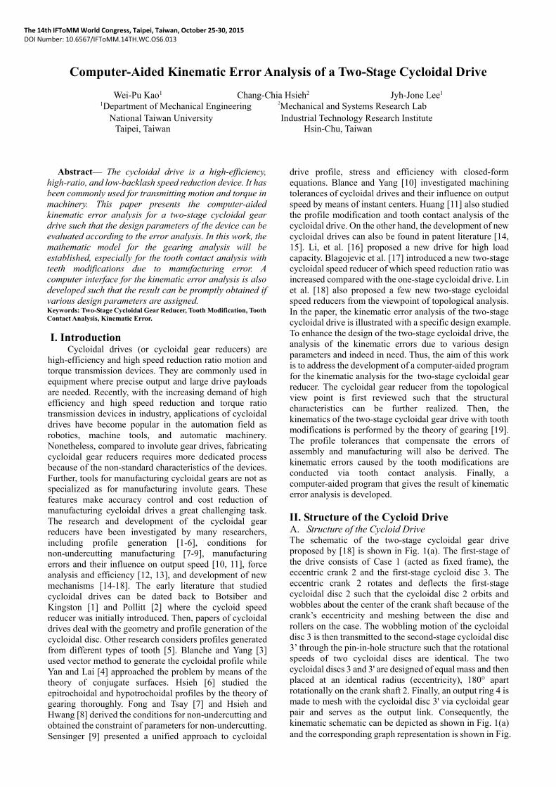
II. Structure of the Cycloid DriveA. Structure of the Cycloid Drive The schematic of the two-stage cycloidal gear drive proposed by [18] is shown in Fig. 1(a). The first-stage of the drive consists of Case 1 (acted as fixed frame), the eccentric crank 2 and the first-stage cycloid disc 3. The eccentric crank 2 rotates and deflects the first-stage cycloidal disc 2 such that the cycloidal disc 2 orbits and wobbles about the center of the crank shaft because of the crank’s eccentricity and meshing between the disc and rollers on the case. The wobbling motion of the cycloidal disc 3 is then transmitted to the second-stage cycloidal disc 3’ through the pin-in-hole structure such that the rotational speeds of two cycloidal discs are identical. The two cycloidal discs 3 and 3' are designed of equal mass and then placed at an identical radius (eccentricity), 180° apart rotationally on the crank shaft 2. Finally, an output ring 4 is made to mesh with the cycloidal disc 3' via cycloidal gear pair and serves as the output link. Consequently, the kinematic schematic can be depicted as shown in Fig. 1(a) and the corresponding graph representation is shown in Fig.
14th World Congress in Mechanism and Machine Science, Taipei, Taiwan, 25-30 October, 2015
1(b).
(a) Kinematic schematic
(b) Graph representation
Fig. 1 A new two-stage cycloidal gear reducer
In the graph representation, the vertex represents link, thin edge represents turning pair, heavy edge represents cycloidal gear pair (CG), heavy dashed edge represents pin-in-hole pair (C), and p, q represent different levels of axis of rotation. The graph representation of the gear reducer can quickly help the designer realize the essential topological information about which link is connected to which other links by what types of joints.
B. Gear Ratio Analysis The angular velocity analysis of the mechanism
shown in Fig. 1(a) can be easily conducted using the angular velocity analysis method of the epicyclic gear trains. Let 1, 2, 3, 3', and 4 respectively represent the angular velocities of case (1), crank (2), first stage cycloidal disc (3), second stage cycloidal disc (3') and output ring (4). Since Crank 2 serves as the carrier for the first stage cycloidal train unit 3-2-1 and second stage cycloidal train unit 3'-2-4, the angular velocity relation can be written for each train unit as:
3 2 1
1 2 3
z
z
(1a)
3 2 4
4 2 3
z
z
(1b)
where z1 and z4 is respectively the number of rollers on case and output ring; z3 and z3' is respectively the number of teeth (lobes) on the 1st-stage and 2nd-stage cycloidal
discs. Meanwhile, the case is fixed as frame, 1=0, and the angular velocity of the 1st-stage cycloidal disc is equivalent to that of the 2nd-stage cycloidal disc, 3= 3'. After substituting these conditions into Eqs. (1a) and (1b) and rearranging, the speed reduction ratio m can be derived as:
2
4 1 3
3 4
1
1
in
out
mz z
z z
(2)
Theoretically, if the ratio in the denominator of Eq. (2) approaches to one, the speed reduction ratio m can become very large. In case one-tooth difference between the cycloidal disc and the mating ring is applied, i.e., z1=z3+1 and z4=z3' +1, the speed reduction ratio m can be further simplified as:
3 3 3
3 3
z z zm
z z
(3)
It can be seen that the speed reduction ratio m can be maximized if the difference of teeth number between the first-stage and second-stage cycloidal discs is one and the teeth numbers of cycloidal discs maximize. Further, if z3= z3', which implies the first-stage cycloidal train unit and the second-stage cycloidal train unit are identical, the output ring becomes stationary as the Case (link 1).
III. Profile Generation and Modification A. Profile Generation
In this section, formula for profile generation will be established for later use. As shown in Fig. 2, coordinate systems Sf (xf-Of-yf), Sp (xp-Op-yp), and Sc (xc-Oc-yc) respectively represents the coordinate system fixed on the frame, circular roller, and cycloidal disc. In the figure, c is the rotation angle of Sp with respect to Sf, p is the rotation angle of Sc with respect to Sf, e is the eccentricity (distance OpOf), rp is the roller position (distance from roller center to Op), rrp is the radius of the roller, P is the contact point between roller surface and cycloidal disc, and is the parameter of the contact point P on the roller.
Fig. 2 Coordinate systems for profile generation
To generate the cycloidal profile, it is necessary to

14th World Congress in Mechanism and Machine Science, Taipei, Taiwan, 25-30 October, 2015
obtain the coordinate of point P with respect to the coordinate system Sc. Thus, the coordinate transformation matrices must be derived. Equations (4) ~ (6) are the coordinate transformation matrices, where Mji denotes the coordinate transformation matrix which transfers coordinate i to coordinate j.
cos( ) sin( ) 0
sin( ) cos( ) 0 0
0 0 1 0
0 0 0 1
p p
p pfp
e
M (4)
cos( ) sin( ) 0 0
sin( ) cos( ) 0 0
0 0 1 0
0 0 0 1
c c
c ccf
M (5)
=
cos( ) sin( ) 0 cos( )
sin( ) cos( ) 0 sin( )
0 0 1 0
0 0 0 1
cp cf fp
p c p c c
p c p c c
e
e
M M M
(6)
Since the roller is meshing with the cycloidal disc, the relation c = pnp /nc holds for p and c, where nc and np are respectively the number of teeth of cycloidal disc and the number of rollers. In this work, the one-tooth difference design is adopted, ie., np= nc+1. Replacing c with p, and substituting into Eq. (6), yields
cos( ) sin( ) 0 cos( )
sin( ) cos( ) 0 sin( )
0 0 1 0
0 0 0 1
p p p p
c c c
p p p pcp
c c c
ne
n n n
ne
n n n
M (7)
The coordinate of P in Sp, ( )p
pr , can be written as
Eq.(8).
( )
cos( )
sin( )
0
1
p rp
rppp
r r
r
r (8)
Then, the coordinate of P in Sc,( )p
cr , can be obtained as:
( ) ( )
cos( ) cos( ) cos( )
sin( ) sin( ) sin( )
0
1
p pc cp p
p p p pp rp
c c c
p p p pp rp
c c c
nr r e
n n n
nr r e
n n n
r M r
(9)
Once the design parameters rp, rrp, np, nc, and e are given, Eqs. (9) can be used to generate cycloidal profiles.
B. Meshing Equation
Using the theory of gearing, the profile equation of the cycloidal disc can be obtained via the coordinate transformation and the equation of meshing:
0c c
p
r rk (10)
After deploying, we can obtain the equation of meshing as Eq. (11) and α function in terms of input parameter p as Eq. (12). Substituting α into Eq. (9), one can obtain the cycloidal profile as shown by Eq. (13).
sin( ) sin( ) 0p rp prp p
c c
r r nr e
n n (11)
1 sin( )tan
cos( ) /p
p p pr n e
(12)
1
1
sin( )cos( ) cos(tan ) cos( )
cos( ) /
sin( )sin( ) sin(tan ) sin( )
cos( ) /
0
1
c
p p p p pp rp
c p p p c c
p p p p pp rp
c p p p c c
nr r e
n r n e n n
nr r e
n r n e n n
r
(13)
C. Profile Modification It is inevitable that there exit errors for the mechanical
parts due to assembly and manufacturing process. Therefore, it is necessary to modify the cycloidal gear profile to compensate those errors. In this work, only modification of the profile is considered since the thickness of the cycloidal disc is usually small compared to other dimensions in the disc and thus errors due to non-parallel shaft angle can be negligible. Meanwhile, the eccentricity e is small and its error can be incorporated into rp and rrp. Parameters that may influence the profile are then the roller radius rp and roller position rrp. Therefore, two profile modification parameters as the roller position (drp) and the roller radius (drrp) are taken into account. They both can be the positive or negative values.
IV. Kinematic Error Analysis A. Tooth Contact Analysis
The tooth contact analysis (TCA) can provide

14th World Congress in Mechanism and Machine Science, Taipei, Taiwan, 25-30 October, 2015
information about surface contact condition at every instant and simulate the transmission errors caused by profile modification [18]. Before proceeding TCA, coordinate systems for assembly must be defined. As shown in Fig. 3, coordinate systems Sc1 and Sr1 are respectively the coordinate system attached to 1st-stage cycloidal disc and its mating roller; coordinate systems Sc2 and Sr2 are respectively the coordinate system attached to 2nd-stage cycloidal disc and its mating roller; and Sf is the fixed frame for assembly. Note that Sr1 coincides with Sf. In addition, 1 is the crank input (positive as counterclockwise); 2 is the angle for the 1st-stage and 2nd-stage disc (positive as clockwise); and 3 is the angle of output link (positive as counterclockwise). Meanwhile, p1/nc1 and p2/nc2 are angular parameters for the contact point position of the 1st-stage and 2nd-stage cycloidal disc while β1 and β2 are angular parameters for the contact point position of the 1st-stage and 2nd-stage roller. In this work, the coordinates will be expressed with respect to the fixed frame while performing TCA. Therefore, following transformation matrices can be established.
Fig. 3 Coordinate systems for TCA
1
2 2 1
2 2 1,
cos( ) sin( ) 0 cos( )
sin( ) cos( ) 0 sin( )
0 0 1 0
0 0 0 1
f c
e
e
M (14)
2
2 2 1
2 2 1,
cos( ) sin( ) 0 cos( )
sin( ) cos( ) 0 sin( )
0 0 1 0
0 0 0 1
f c
e
e
M (15)
2
3 3
3 3,p
cos( ) sin( ) 0 0
sin( ) cos( ) 0 0
0 0 1 0
0 0 0 1
f
M (16)
The 1st-stage cycloidal disc equation with tooth modification as
1
1 1 1 1
1 1 1 1
1 1 1
1 1 1 1
1 1 1 1
1 1 1
1
1
( )cos( ) ( )cos( ) cos( )
( )sin( ) ( )sin( ) sin( )
0
1
c
p p p pp p rp rp
c c c
p p p pp p rp rp
c c c
nr dr r dr e
n n n
nr dr r dr e
n n n
r
(17)
in which 1
1 1 1 1
11
sin( )tan
cos( ) ( ) /p
p p p pr dr n e
.
The 1st-stage roller equation as
1 1
1
1
1
1
cos( )
sin( )
0
1
p rp
rpp
r r
r
r (18)
The 2nd-stage cycloidal disc equation with tooth modification as
2
2 2 2 2
2 2 2 2
2 2 2
2 2 2 2
2 2 2 2
2 2 2
2
2
( )cos( ) ( )cos( ) cos( )
( )sin( ) ( )sin( ) sin( )
0
1
c
p p p pp p rp rp
c c c
p p p pp p rp rp
c c c
nr dr r dr e
n n n
nr dr r dr e
n n n
r
(19)
in which 2
2 2 2 2
12
sin( )tan
(cos( ) ( ) / )p
p p p pr dr n e
.
The 2nd-stage roller equation as
2 2
2
2
2
2
cos( )
sin( )
0
1
p rp
rpp
r r
r
r (20)
Meanwhile, the contact normals of the cycloidal disc,
1cn , and roller,
1pn , for the 1st-stage cycloidal unit are
shown by Eq. (21), and the contact normals of the cycloidal
disc, 2cn , and roller,
2pn , for the 2nd-stage cycloidal disc
are shown as Eq. (22).

14th World Congress in Mechanism and Machine Science, Taipei, Taiwan, 25-30 October, 2015
1
11
1
1
c
cc
rk
nr
k and
1
11
1
1
p
pp
rk
nr
k (21)
2
22
2
2
c
cc
rk
nr
k and
2
22
2
2
p
pp
rk
nr
k (22)
Thus, a family of cycloidal tooth and roller surfaces can be generated in the fixed coordinate system Sf by the matrix transformation:
1 11
,cr f c cf M r (23)
2 22,cr f c cf M r (24)
2 22,pr f p pf M r (25)
Likewise, the unit normals for contact surfaces can be represented in Sf by the matrix equations:
1 11
,cn f c cf L n (26)
2 22,cn f c cf L n (27)
2 22,pn f p pf L n (28)
Where L is a 33 matrix which is the upper left 33 submatrix of matrix M. The condition for the continuous contact of the surfaces requires contact surfaces be in continuous tangency, i.e., their contact position vectors and normals coincide at any instant. Thus, we can write the following equations:
1 111 1 2( ) ( , , )
cp r p r f (29)
1 111 1 2( ) ( , , )
cp n p n f (30)
22 22 3 1 2( , ) ( , , )
p cr r p f f (31)
22 22 3 1 2( , ) ( , , )
p cn n p f f (32)
Detail expressions for the above equations can be referred to [20]. It can be seen that Eqs. (29) and (30) provide three independent equations in three unknowns, 2, p1, and 1, and one known crank input 1. Thus, tooth contact for the 1st-stage cycloidal disc can be solved. Then, Eqs. (31) and (32) also provide three independent equations in four unknown, 2, p2, 2 and 3. Note that 2 is already known. Therefore, tooth contact for the 2nd-stage cycloidal disc can also be solved. B. Kinematic Error
Once the output angle 3 is obtained, the transmission error 3 can be written as the difference between simulated 3 and theoretical output, 3, namely,
∆ϕ3 = ϕ3 – m ϕ1 (33)
The maximum kinematic error is the value between the highest and lowest values of the kinematic error curve as
shown in Fig. 4.
Fig. 4 Kinematic error curve
V. Computer-Aided Analysis A. Initial Setting of Two-Stage Cycloidal Reducer
A computer program for the kinematic error analysis with user interface has been developed. This program allows the user to input the design parameters for the two-stage cycloidal drive and then simulates the kinematic errors. Following are the descriptions for the computing algorithm.
Initial positions for the cycloidal discs and their respective mating roller are set as follows. A roller on the Case and a roller on output ring are placed along the x-axis of the fixed frame. Note that both the centers for the pitch circles respectively formed by the roller centers on the Case and output ring are idential to the origin of the fixed coordinate. The 1st stage cycloidal disc is initially placed such that a concave part is in contact with the aforementioned roller on Case. The 2nd stage cycloidal disc is initially placed such that a convex part is in contact with the aforementioned roller on output ring. The above positions define the 0 degree for the position of both cycloidal discs. The roller No. 1 is then labelled as the first roller that is next to the aforementioned roller. Rest of the rollers are then placed and numbered in a counter-clockwise sense. The initial positions for the 1st stage (black solid line) and 2nd stage (red dashed line) cycloidal discs and their mating rollers are shown in Fig.5.
Fig. 5 Initial positions of the cycloidal drive
B. User Interface As shown in Fig. 6, a user interface is established to
allow the designer to input the design parameters for the
3 2
1
X
1
2 3
14th World Congress in Mechanism and Machine Science, Taipei, Taiwan, 25-30 October, 2015
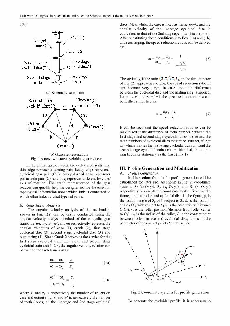
cycloidal drive. On the left side of the interface, design parameters such as the eccentricity (e), number of teeth (lobes) of cycloidal discs (nc), roller position Rp, position modification dRp, roller radius Rrp, and roller radius modification dRrp are to be given by the user. On the right hand side of the interface, the program shows the kinematic error distribution versus the rotation of the crank, for both first stage and second stage (also overall). A computer program also has been developed to detect the tooth contact condition for each cycloidal tooth and calculate its value. Algorithm for comparing the values among various teeth is also required to determine the correct contact position. Detailed program can be referred to [20].
Fig. 6 Computer-aided kinematic Error Analysis,
Example 1
C. Design Examples
Two examples are illustrated to show the computer-aided analysis of the kinematic errors for the two-stage cycloidal drive.
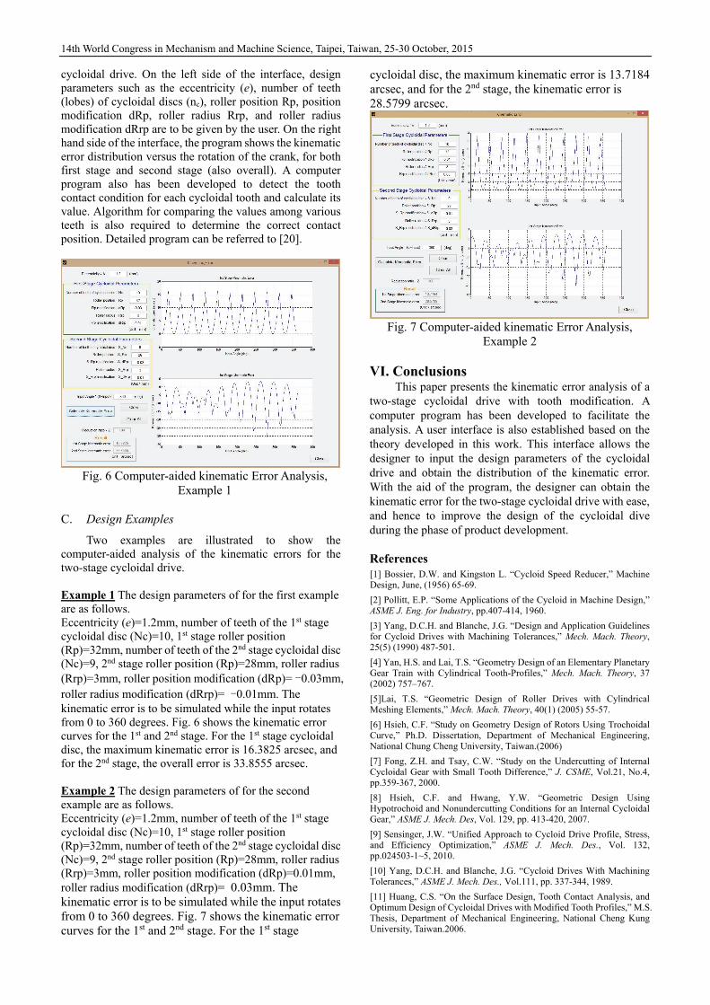
Example 1 The design parameters of for the first example are as follows. Eccentricity (e)=1.2mm, number of teeth of the 1st stage cycloidal disc (Nc)=10, 1st stage roller position (Rp)=32mm, number of teeth of the 2nd stage cycloidal disc (Nc)=9, 2nd stage roller position (Rp)=28mm, roller radius (Rrp)=3mm, roller position modification (dRp)= -0.03mm, roller radius modification (dRrp)= -0.01mm. The kinematic error is to be simulated while the input rotates from 0 to 360 degrees. Fig. 6 shows the kinematic error curves for the 1st and 2nd stage. For the 1st stage cycloidal disc, the maximum kinematic error is 16.3825 arcsec, and for the 2nd stage, the overall error is 33.8555 arcsec. Example 2 The design parameters of for the second example are as follows. Eccentricity (e)=1.2mm, number of teeth of the 1st stage cycloidal disc (Nc)=10, 1st stage roller position (Rp)=32mm, number of teeth of the 2nd stage cycloidal disc (Nc)=9, 2nd stage roller position (Rp)=28mm, roller radius (Rrp)=3mm, roller position modification (dRp)=0.01mm, roller radius modification (dRrp)= 0.03mm. The kinematic error is to be simulated while the input rotates from 0 to 360 degrees. Fig. 7 shows the kinematic error curves for the 1st and 2nd stage. For the 1st stage
cycloidal disc, the maximum kinematic error is 13.7184 arcsec, and for the 2nd stage, the kinematic error is 28.5799 arcsec.
Fig. 7 Computer-aided kinematic Error Analysis,
Example 2
VI. Conclusions This paper presents the kinematic error analysis of a
two-stage cycloidal drive with tooth modification. A computer program has been developed to facilitate the analysis. A user interface is also established based on the theory developed in this work. This interface allows the designer to input the design parameters of the cycloidal drive and obtain the distribution of the kinematic error. With the aid of the program, the designer can obtain the kinematic error for the two-stage cycloidal drive with ease, and hence to improve the design of the cycloidal dive during the phase of product development.
References [1] Bossier, D.W. and Kingston L. “Cycloid Speed Reducer,” Machine Design, June, (1956) 65-69.
[2] Pollitt, E.P. “Some Applications of the Cycloid in Machine Design,” ASME J. Eng. for Industry, pp.407-414, 1960.
[3] Yang, D.C.H. and Blanche, J.G. “Design and Application Guidelines for Cycloid Drives with Machining Tolerances,” Mech. Mach. Theory, 25(5) (1990) 487-501.
[4] Yan, H.S. and Lai, T.S. “Geometry Design of an Elementary Planetary Gear Train with Cylindrical Tooth-Profiles,” Mech. Mach. Theory, 37 (2002) 757–767.
[5]Lai, T.S. “Geometric Design of Roller Drives with Cylindrical Meshing Elements,” Mech. Mach. Theory, 40(1) (2005) 55-57.
[6] Hsieh, C.F. “Study on Geometry Design of Rotors Using Trochoidal Curve,” Ph.D. Dissertation, Department of Mechanical Engineering, National Chung Cheng University, Taiwan.(2006)
[7] Fong, Z.H. and Tsay, C.W. “Study on the Undercutting of Internal Cycloidal Gear with Small Tooth Difference,” J. CSME, Vol.21, No.4, pp.359-367, 2000.
[8] Hsieh, C.F. and Hwang, Y.W. “Geometric Design Using Hypotrochoid and Nonundercutting Conditions for an Internal Cycloidal Gear,” ASME J. Mech. Des, Vol. 129, pp. 413-420, 2007.
[9] Sensinger, J.W. “Unified Approach to Cycloid Drive Profile, Stress, and Efficiency Optimization,” ASME J. Mech. Des., Vol. 132, pp.024503-1~5, 2010.
[10] Yang, D.C.H. and Blanche, J.G. “Cycloid Drives With Machining Tolerances,” ASME J. Mech. Des., Vol.111, pp. 337-344, 1989.
[11] Huang, C.S. “On the Surface Design, Tooth Contact Analysis, and Optimum Design of Cycloidal Drives with Modified Tooth Profiles,” M.S. Thesis, Department of Mechanical Engineering, National Cheng Kung University, Taiwan.2006.

14th World Congress in Mechanism and Machine Science, Taipei, Taiwan, 25-30 October, 2015
[12] Malhotra, S. K. and Parameswaran, M. A. “Analysis of A Cycloid Speed Reducer,”Mech. Mach. Theory, 18 (6), 1983. 491-499.
[13] Gorla, C., Davoli, P., Rosa F., Longoni, C., Chiozzi, F. and Samarani, A. “Theoretical and Experimental Analysis of a Cycloidal Speed Reducer,” ASME J. Mech. Des., 130, 2008. 112604-1~8.
[14] Janek, B. “Gear System,” US Patent No. 5908372, Jun (1999)
[15] Nakamura, K. “Speed Reduction Device,” US Patent No. 7811193B2, Oct., 2010.
[16] Li, X., He, W. Li, X. and Schmidt, L.C. “A New Cycloid Drive with High-Load Capacity and High Efficiency,” ASME J. Mech. Des, 126 (4), 2004.
[17] Blagojevic, M., Marjanovic, N., Djordjevic Z., Stojanovic, B., and Disic, A. “A New Design of a Two-Stage Cycloidal Speed Reducer,” ASME J. Mech. Des, 133, 2011. 085001-1~7.
[18] Lin, Wan-Sung, Shih, Yi-Pei and Lee, Jyh-Jone “Design of a Two-Stage Cycloidal Gear Reducer with Tooth Modifications,” Mechanism and Machine Theory, 79, 2014, pp. 184-197.
[19] Litvin, F. L. and Fuentes, A. Gear Geometry and Applied Theory, 2nd Edition, Cambridge University Press, Cambridge, UK, 2004.
[20] Lin, W.S. “Kinematic Error Analysis and Design of a Two-Stage Cycloidal Drive,” M.S Thesis, Dept. of Mech. Engr., National Taiwan University, Taiwan. (2013)
Related Documents