-- r'u /-" ORC 78-14 LLAUGUST 1978 COMPUTER-AIDED FAULT TREE ANALYSIS by RANDALL R. WILLIE 10. I: ... I OPERATIONS RESEARCH Tis docuinothabeenppmved C E N T for puboice roloase• =d ad ib CENTER OFCifriA u " ingtL& UNIVERSITY OF CALIFORNIA W ER(ELEY

Welcome message from author
This document is posted to help you gain knowledge. Please leave a comment to let me know what you think about it! Share it to your friends and learn new things together.
Transcript
-- r'u /-" ORC 78-14LLAUGUST 1978
COMPUTER-AIDED FAULT TREE ANALYSIS
by
RANDALL R. WILLIE
10.
I:
... I
OPERATIONSRESEARCH Tis docuinothabeenppmved
C E N T for puboice roloase• =d ad ib
CENTER OFCifriA u " ingtL&
UNIVERSITY OF CALIFORNIA W ER(ELEY
ItCOMPUTER-AIDED FAULT TREE ANALYSISt
by
Randall R. WillieOperations Research Center
University of California, Berkeley
AUGUST 1978 ORC 78-14
This research has been partially supported by the Otfice of NavalResearch under Contract N00014-75-C-0781, the Air Force Office ofScientific Research (AFSC), USAF, under Grant AFOSR-77-3179 and theLawrence Livermore Laboratory under Purchase Order No. 7800103 withthe University of California. Reproduction in whole or in part ispermitted for any purpose of the United States Government.
tThe computer program FTAP is available from NISEE/Computer Applica-
tions, Davis Hall, University of California, Berkeley, California94720, (415) 642-5113.
J

ISCLAI ME1 ý
THIS DOCUMENT IS BEST
QUALITY AVAILABLE. THE COPY
N-RNISHED TO DTIC CONTALNED
A SIGNIFICANT NUMBER OF
',AC" "Ih••1.- DO NOT
4-EGI~BTY
REPRODUCED FROMBEST AVAILABLE COPY

UnclassifiedqCU..ýITY CLASSIFICATION OF THIS PAGE (fton Dal* Emotedet)
READ INSTRUCTIONSREPORT DOCUMENTATION PAGE BEFORE COMPLETING FORM
.GOT ACCESSION NO. 3. RECIPIENT'S CATALOG NUMBER
ORC VE7
COMPUTrER-AIDED FAULT TREE AN.YS~ Research
6. PERFORMING 0 MIENa
7. A TW R~e _ZNTIRACT OR GRANT NUM!S~a
9. PERFORMING ORGANIZATION NAME ANG ACCRESSARA&WICUT UEN
Operations Research CenterUniversity of California NR 042 238Berkeley, California 94720
It. CONTROILLING OISWICK NAME AND ADDRESS ,- LRP5~AT--
Office of Naval Research Aumot 448Departmens-. of the Navy /Arlington, Virginia 22217 103
T4. -MONITORINrG AGENCY NAME a AUDRIESS(if different fro'.i Controlling Office) 15. SECURITY CLASS. Wa this ,0eort)
Unc lass if iedSC. E(C.ASSIPFICAT1ONI OOWNGNAAOING
SCNIEDULIE
IS. DISTRIBUTION SfATEMCNT (of this Report)
Approved for public release; distribution unlimited.
17. DISTRIBUTION STATEMENT (of IA. Pnb*Ict entered in Block 20, it dgff.,u.,t from Repeart)
Ifl. SUPPLEMENTARY NOTES
Also supported by the Air Force Office of Scientific Research (AFSC), USAF,under Grant AFOSR-77-3179 and the Lawrence Livermore Laboratory underPurchase Order No. 7800103.
IS. KEY WORDS (Contlnuma n Poers* aidej it fl*comyC Und identity by block nuatibe')
Fault TreeLogic TreeMinimal Cut SetPrime implicant
ZO. ABSTRACT (Codtioula* on reverse aid* it necessary and i*d~fiit by block numsb.,)
(SEE ABSTRACT)
DD I OA"W'7, 1473 EDITION OF IHOV 65 IS OBSOLETE UnclassifiedS/N 102-F-04-6601
~2 ~ ,'~~-*Z~ SECURITY CLASSIFICATION OF THIS PAGE (USI erl tw~

ACKNOWLEDGMENT
I am deeply indebted to Professor Richard E. Barlow of University
of California, Berkeley for his guidance and encouragement in the pre-
Sparation of this report and the associated computer program. I am
also grateful for his cheerful patience as I consistently under-
estimated the remaining time to complete this project.
Dr. Howard Lambert of Tera Corporation (formerly of Lawrence
Livermore Laboratories) deserves special thanks for providing a number
of large fault trees to test the algorithms and program logic. Finally,
I am grateful to Dr. Richard Worrell of Sandia Laboratories for a
stimulating discussion of fault tree methods during his visit to
Berkeley in November, 1977.
S......................................
.........

ABSTRACT
Part I of this report discusses a computer-oriented methodology
for deriving minimal cut and path set families associated with arbitrary
fault trees. Part II describes the use of the Fault Tree Analysis
Program (FTAP), an extensive FORTRAN computer package that implements
the Part I methodology. An input fault tree to FTAP may specify the
system state as any logical function of subsystem or component state
variables or complements of these variables. When fault tree logical
relations involve complements of state variables, the analyst may
instruct FTAP to produce a family of prime imp•ioants, a generalization
of the minimal cut set concept. FTAP can also identify certain sub-
systems associated with the tree as system modules and provide a
collection of minimal cut set families that essentially expresses the
state of the system as a function of these module state variables.
Another FTAP feature allows a subfamily to be obtained when the family
of minimal cut sets or prime implicants is too large to be found in
its entirety; this subfamily consists only of sets that are
interesting to the analyst in a special sense. K
'I.•• . . . . : : ,::,,r • •,',:,• ,= :- • • . • • d __ _ • -:

TABLE OF CONTENTS
Page
INTRODUCTION .......................... ........................... 1
PART I: METHODS FOR COMPUTER-AIDED FAULT TREE ANALYSIS .... ...... 4
1.1 Boolean Expressions ............... ................... 41.2 Fault Tree Fundamentals .............. ................. 8
1.2.1 Fault Tree Definitions ............ .............. 91.2.2 The MOCUS and MICSUP Methods .... ........... ... 161.2.3 General Framework for Implicant Elimination . . . 23
1.3 Simple Modules ............... ...................... .. 24
1.3.2 Application of Simple Modules to Implicant
Families ............ ..................... 281.3.3 A Method for Identifying Modular Subtrees. ..... ... 33
1.4 Obtaining Implicant Families Associated withModular Subtrees .............. ................... ... 40
1.4.1 The MSDOWN Method ......... ................. ... 411.4.2 The MSUP Method ......... ................. .... 491.4.3 The Nelson Method ......... ................ ... 551.4.4 Comments on the Choice of Method ... ......... ... 61
PART 11: USE OF THE FAULT TREE ANALYSIS PROGRAM . .. .. .. . .. 66
11.1 General Input Structure ......... ................. ... 6711.2 Fault Tree Specification ......... ................ .. 6911.3 Execution Instructions ............ ................ .. 7211.4 Option Instructions ....... ................. .... 75
11.4.1 Fault Tree Modification (TRUE, FALSE) .. ...... .. 7611.4.2 Gate Event Selection (PROCESS, ALL) .. ....... .. 7811.4.3 Methodology Specification (PRIME, ALLNEL,
NELSON, MSUP, MSDOWN, WRKFILES, MSONLY,DUAL, UPWARD, MINCHECK) . . ............ 79
11.4.4 Control of Printed and Punched Output(MSPRINT, STATUS, DSTATUS, PUNCH,
MSPUNCH, NOPRINT) ...... ............... ... 8311.4.5 Implicant Elimination Based on Size and
Importance (MAXSIZE, MODSIZE, IMPORT) .. ...... .. 89
11.5 Program Implementation ......... ................. ... 9211.6 Specifications for Assembler Routines .... .......... ... 95
REFERENCES .................. ............................. .... 97
I I I I I I I I I

II
INTRODUCTION
The analyst who seeks to determine reliability characteristics
of a complex system, such as a nuclear reactor, in terms of the
reliability characteristics of its subsystems and components confronts
a number of difficult tasks. One task involves identification either
implicitly or explicitly, of logical modes of system si'. .wis or
failure, that is, various distinct combinations of subsystems whose
mutual success or failure implies success or failure of the entire
system. Minimal cut set and path set families, tools familiar to
reliability analysts for some time, provide an explicit representation
of these modes. These families are useful not only re~valuating
reliability characteristics of a system but also as tool to
guide system modifications for enhancing reliability.
A widely used concept in reliability analysis of complex systems
is that of a fault tree. Fault tree methods are based on the observa-
tion that the system state, either working or failed, can usually be
expressed as a Boolean relation between states of several large,
readily identifiable subsystems. The state of each subsystem in
turn depends on states of simpler subsystems and components which
compose it, so the state of the system itself is determined by a
hierarchy of logical relationships between states of subsystems.
A fault tree is a graphical representation of these relationships.
At the lowest level of the hierarchy are sulsystems whose success or
failure dependence is not further described. If reliability informa-
tion is available for these lowest level subsystems, then it may be
possible to use this information to deduce reliability characteristics
of the system itself.
S-I

2
An analyst who prepares a system fault tree often does so with
the intention of utilizing it to obtain certain minimal cut (or path)
set families in terms of these lowest level subsystems and components.
Part I of this discussion outlines a computer-oriented methodology
for deriving such families for an arbitrary fault tree. Part II
describes the use of the Fault Tree Analysis Program (FTAP), an
extensive computer package, written mostly in FORTRAN, which implements
the Part I methodology.
FTAP has a number of useful features that make it well-suited
to nearly all fault tree applications. An input fault tree to this
program may specify the system state as any logical function of sub-
system or component state variables or complements of these variables;
thus, for instance, exclusive -. or type relations may be formed.
When fault tree logical relations involve complements of state
variables, the concept of a minimal cut set family is no longer
particularly useful, so in this case the analyst may instruct FTAP
to produce a family of prime implicants, a generalization of the
minimal cut set concept. The program offers the flexibility of
several distinct methods of generating cut set families, and these
methods may differ considerably in efficiency, depending on the
particular tree analyzed. FTAP can also identify certain subsystems
as system modules and provide a collection of minimal cut set families
that essentially expresses the state of the system as a function of
these module state variables. This collection is a compact way of
representing the same information as contained in the system minimal
cut set family in terms of lowest level subsystems and components.
Another feature allows a useful subfamily to be obtained when a family

3
of minimal cut sets or prime implicancs is too large to be found
in its entirety; this subfamily may consist of only sets not con-
taining more than some fixed number of elements or only sets that are
"interesting" to the analyst in a special sense. Finally, the analyst
can modify the input fault tree in various ways by declaring state
variables identically true or false.
A number of computer programs are currently available for obtaining
minimal cut set families from fault trees, and some of these programs
are mentioned in the discussion of Part I. One very capable package
that deserves special mention is the SETS program developed by
Dr. Richard Worrell of Sandia Laboratories [18], In addition to
fault trde analysis, SETS manipulates arbitrary Boolean expressions.
For fault tree work, several features of FTAP and SETS are similar.
and both programs have been used with good results during the past
year in nuclear reactor safety studies conducted by Dr. Howard Lambert
of the Lawrence Livermore Laboratories.
!z(

4
PART I
METHODS FOR COMPUTER-AIDED FAULT TREE ANALYSIS
The first two sections below essentially provide notation and
background information for the procedures presented in Sections 1.3
and 1.4. The notation introduced in Section I.1 has been chosen
both to reflect the computer implementation of these procedures and
to relate their various operations to manipulation of Boolean ex-
pressions. In Section 1.2, fault trees and implicant families are
formally defined, and two quite well-known fault tree algorithms,
MOCUS and MICSUP, are reviewed.
The reader who is primarily interested in using FTAP should look
over Section 1.1 and Subsections 1.2.1, 1.2.2, 1.3.1, 1.3.2, and 1.4.4
before skipping to Part II.
I.1 Boolean Expressions
The reader is assumed to be familiar with the rudiments of Boolean
algebra; a refcrence such as [16], for instance, is more than adequate
as background. Let xl, ... , xq be Boolean variables independently
taking on values of 0 or 1 , and let x • (xl, ... , x ) be a vector
of O's and l's representing an arbitrary choice of these values.
We denote complementation by negation of subscripts: For any u
in the set U - (Io .... , q] , x (OF - x ) is written as x.U U --U
The index set for complements is -U 2 ., ..- q] ,and (u,-u)
is a complementary pair of indices.
SjI

5
Expressions may be formed using x, .... x , x ... ,X
and the ordinary Boolean relations of product and sum. An arbitrary non-
empty family I of subsets of U U (-U) (not necessarily distinct) is
identified with the Boolean sum-of-products expression
Sr[ x iTel itl
The notation /I/x denotes the value of this expression for a given
vector x of O's and l's , that is,
/11x Emax min x n x,- el (I i fI ItT itl
/l/ may then be taken as a Boolean function mapping each vertex of
the q-dimensional unit cube into 0 or 1 . Given nonempty families
I , 3 , and K of subsets of U U (-U) , /I/ = IJI means that for all
x /I/n /-/n . Similarly, if for all x /I/x - /J/x + /K/x
(/I/n - /3/n • /K/n) , write /I/ /F / + /K/ (/I/ /J/ • /K/) . For
the null family (0) we define /0/ ' 0 ; although for the family con-
taining only the empty set ([01) , /[r]/ is left undefined.
The union of families I and J clearly has the property
/II U J3/ / / + /j/
Now suppose U - {l,2,3} and T1 - [(2,31] 12 - [(1,2,31] and
13 - [{-1,-3,3}] For any x i(xx 2 ,x 3 ) , /I3/x - xx_ 3 3 - 0 ,
so /I1 U 12U U 13 1 U 12/ ,and 13 need not be considered
further. Thus to simplify the discussion, it is assumed that no set
of a fcily contains a complementary pair; whenever a new family is
constructed, any sets containing complementary pairs are simply eliminated.

6
In the example above it is also true that for all x
/IfI/x /12 U 13 /x , since (2,31 C (1,2,31 , and thus /I /x - I
whenever /1 2 /x - I . A family is said to be minimal if all sets are
distinct and for any two sets of the family, neither is a subset of the
other. For any family I , let m[1] (the "minimization" of 1) be the
minimal family obtained by eliminating duplicate sets and those which
contain another set of I . For instance, m[[{2,3},[l,2,3}]I [(2,31]
Of course, for any I , /m[l]/ /I/
Next, the product family Ix J of two families 1 # 0 and
J # 0 is defined by [I U J I I v I , J e J] ; that is, I x J consists
of all possible sets that may be formed by taking the union of a set
from I and a set from J , excluding unions which contain comple-
mentary pairs. The product is assumed to be empty if either I or J
is empty. Evidently, 'I x J/ /I/ • /J/ since for all x
(IE1 iel JEJ jeJ
KETxJ kcK k
We will need one additional concept. Given a nonempty family I
of subsets of U U (-U) , the dual family of I , denoted by d[I]
consists of all distinct sets J such that J f1 I 0 for each I e Iand no subset of J has this property. By definition, d[1j is always
minimal, and though I may not be minimal, it is not difficult to
see d[I] - dm[1]] . In general, d[d[I] # T , though there is one
important case in which equality holds: If 7 is a minimal family
of subsets of U (rather than U U (-U)) then I is called a
clutter, anl d[L] is then known as the blocker of I , usually

7
written as b(I] . It can be shown [5] that b[b[L]] - If I
consists of subsets of U U (-U) , however, then d[i] may be empty;
for instance, let I - [{-l},{lfli
The dual family is useful because it allows us to relate an
expression in product-of-sums form to a sum-of-products form. Some
thought indicates that for all x
", n X, x n iT IE ici l l] iEx
and
ITI ic I led[1] LEI
The following simple propositions will be useful later on:
Proposition I.1.1:
If I 0 0 then for all x , 1 - /d[I]/(l -x) - /I/x , where
1 x • is the vector (1 - xI, ... , i - xn)
This is true because De Morgan's Law gives
x xi- x (-i),Iel icl Id- iLI
and the value of the expression on the right equals
1 - [ li (1l- x)
Ied[i] iel
which is I - /d[I]/(l-x)

8
I Proposition 1.1.2:
If I# 0 and J #0 , then
d[I U J] - m[d[I] x d(J]] .
It is easy to see that d[I U J] C d[l] x d[J] , and each set of
d(1] d(J] equals or contains a set of d[I U J] , so the above
proposition follows. A corollary is:
Proposition 1.1.3:
For I 0 0 and J # 0 if d[d[I]] - I and d[d[J]] i J then
did[1] U d[J]] mr[ x J1
1.2 Fault Tree Fundamentals
Some of the terminology and notation of Subsection 1.2.1 is not
in standard use for fault tree work, partly because fault trees are
traditionally defined in a manner that does not permit system failure
to depend on complements of Boolean state variables for subsystems or
components. Subsection 1.2.2, which presents the MOCUS and MICSUP
methods in the context of this notation and terminology, serves as
a useful introduction to the algorithms of Section 1.4. The final
subsection, 1.2.3, formalizes the idea of a subfamily of "interesting"
cut sets.
I I I ' ' ' ' ' ' 'i

9
1.2.1 Fault Tree Definitions
Formally, a fault tree is an acyclic directed graph (U,A)
where U is the set of nodes and A is the set of arcs. Any pair
of nodes may be joined by at most a single arc, which may be either a
regular arc or a complementing arc. Nodes having no entering arcs we
call basic nodes, and those having one or more entering arcs are called
gate nodes. Those which have no leaving arcs are top nodes; a fault
tree usually has only a single top node. The tree is drawn with arc
paths directed upward from basic nodes and terminating at the top
node. Nodes are numbered by consecutive positive integers, with gates
numbered first. Also, associated with each gate is a logic indicator,
a positive integer £ that may take on any value between 1 and the
number of entering arcs for that gate.
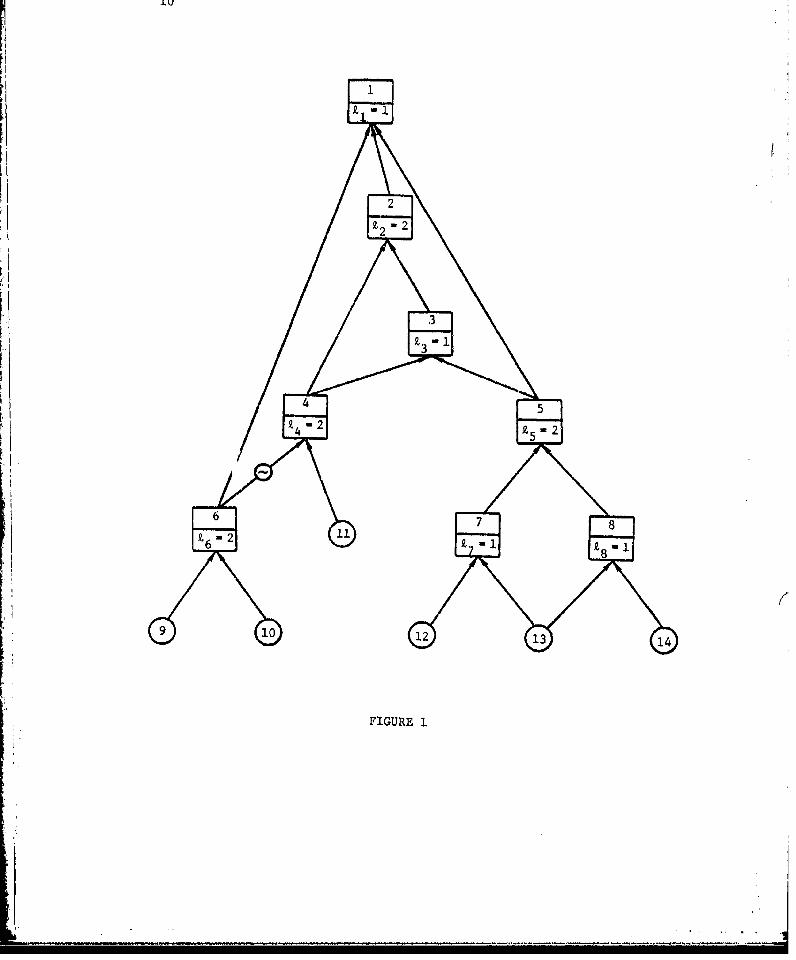
Figure 1 presents a typical fault tree to illustrate the above
terminology. Basic nodes are denoted by circles and gate nodes by
rectangles with node 1 as the top. All arcs are regular with the
exception of the complementing arc joining nodes 6 and 4, and this
arc is distinguished by the symbol "-." The logic indicator for each
gate node appears in the lower half of the rectangle; I ' £3
and Z8 are all I , and Z2 P Z4 , £5 , and 16 are equal to 2.
We say that node v is a subnode of node u if there is an arc
path directed upward from v to u , and v is an immediate subnode
of u if there is a single upward arc from v to u . Nodes 7, 8,
12, 13, and 14, for instance, are subnodes of node 5; whereas, 7 and 8
are the immediate subnodes of 5. When v is a subnode (immediate
subnode) of u , u is sometimes referred to as a supernode
(imdit sueioe of
i2z 2
-2
FIGURE 1
**ji

I,
Finally, given a set of nodes V C U , a downward order on V
is any-complete ordering (J-) of nodes of V such that for anyd
v , w E V , v • w implies v is not a subnode of w . On the other
hand, if w ý. v implies v is not a subnode of w , then the order
S(>) is an upward order. Thus, for V - (2,3,4,5} , 2 - 3 A 5 A 4
U U Uis a downward order and 5 - 4 9 3 9 2 is an upward order.
A fault tree is a convenient representation of a system of Boolean
expressions. Let the set of nodes be U - U1, ... , p - lp,p + 1, ... , q)
where G - {1, ... , p) are gate nodes and B- {p + i, ... , q} are
basic nodes. With the u h node we associate the Boolean variable xu
If u is a basic node, then x may take on the value 0 or 1U
independently of the values of other node variables; thus,
b ... , x) is an arbitrary vector of O's and l's whosep+ q
elements are a particular choice of these values. On the other hand,
if u is a gate node, then the value of x ultimately depends on
values of the independent basic node variables; that is, x is au
Boolean function of the vector b . Gate variable values are determined
by the following scheme: Let D be a set of integers representingu
the immediate subnodes of u . If node v is joined to node u by
a regular arc then v e D ; if v is joined to u by a complementing
arc then -v e D . Note that since only a single arc can join any
two events in the tree, D contains no complementary pair (v,-v)U
The node definition fanily V(Zu,DU) is a family of subsets of
U U (-U) that consists of all possible sets of size X that mayu
be formed from the elements of D where Z is the logic indicatoru P
for node u . The value of x is determined byu

lx.IEV(Zu,D) ic
Each integer i c I may thus be positive or negative, with
xi U(1 - xi) An informal statement of this relation is that
th ,the u gate node is "true" iff 9. or more of its inputs are "true."
The logic indicator satisfies 1 < Z < #D u, where #D represents
the number of elements in D . The value k - 1 corresponds tou u
the "OR" relation between immediate subnode variables (or their
complements); that is,
i cD Xu
whereas, k - #D represents the "AND" relation,
U Ux -1 X
If we apply De Morgan's Law to the general expression for x
u a gate node, a similar expression may be obtained for xu . Let
D - -D {-i Ii e D } ThenD-u -u u
X-1 x • iU- IeV(#Du-.u+l,Du) icI
Since variables x and x are each associated with node u , itu -U
i is coavenient to call both indices u and -u events; -u is the
compoimentary event for node u

13
Let x - (Xl, ... , X p*,xpxp+lp ... , x ) be a vector of O's
and l's Using the notation developed in Section 1.1, x will be
said to be consistent with ':he fault tree if for all gate nodes
u E G , x W /V(Zu,Du)/x . Thus the set of all vectors x consistent
with the fault tree is a subset of vertices of the q-dimensional unit
cube that represents all logically possible combinations of states
of the system and its subsystems and components. If x and x'
are both consistent with the fault tree and have the same values for
basic node variables (i.e., x x x) , then itp+l p~l q q
will be the case that x - x' . So we might write a consistent vector
as x(b) - (xl(b), ... , xp(),Xp(b),b) for some vector
b - (x 1 +I, "'', Xq) of values for basic node variables.
A subset F of U U (-U) is called an implicant set (or just
impZicant) for event i if x1 - 1 for every vector x consistent
with the fault tree such that /[FI/x - 1 . A family F of subsets
of U U (-U) is termed an implioant fcanily for event i if for all
consistent x , xi - /F/x . Thus an implicant family for event i
is a particular collection of implicants for event i . Naturally,
an implicant family F for some event is minimal when m[F] - F
As an example, some of the minimal implicant families for event 1
of the tree of Figure 1 are [{2},(5),{6}] , [[2},{7,8),{9,10}]
and [{3,4},{5},[6}]
Some additional definitions are useful in dealing with fault
trees iavolving complementing arcs. Again, let x - (xi, ... , x)
be any vector of O's and l's (not necessarily consistent with the
fault tree), and suppose P is a Boolean function mapping each such
x into 0 or 1 . A subset P of U U (-U) is a prime impLicant

14
of j if P implies 0 (i.e., c(x) 1 for all x such that
/[P]/x - 1) and no proper subset of P implies 0 . Also, a family
P of distinct subsetn of U U (-U) is a prime implicant fciily for 4 if
for all x O(x) - /P/x and each P e P is a prime implicant for .
The concepts of prime implicants and prime implicant families have
been widely applied in the fields of switching theory and logic,
and the definitions giver here are standard in most introductory
textbooks devoted to these fields. If Pl and P2 are both prime
implicant families for $ , then P, W P so a prime implicant
family is unique.
Specializing the idea of a prime implicant family to our purposes
here, we will call a family P of subsets of U U (-U) a prime
implicant f(=iZy for event i if P is an implicant family for event
i and each P e P is a prime implicant of the Boolean function /P/
Note that if F is an implicant family for event i , the situation
/[F]/x - I for some F e F requires that x- 1 only if x is
consistent with the fault tree; however, whether F is a prime implicant
of IF! depends on all x , not just vectors consistent with the
fault tree. Thus with this definition, two prime implicant families
P) and P for event i need not be the same, since /IP /X - /P 2 /x1 21 2
need only hold for consistent x . But if P1 and P2 are composed
only of sets of basic events, it will be true that P1 - 2 ' In fact,
in sections which follow, we will not be concerned with whether an
implicant family F for event i consists of prime implicants for
L /FI unless F consists only of subsets of basic events or only of
Zarqest simple modulea for event i , which will be introduced in
Section 1.3.

15
As an example, the family F - [{9,10},(l2,l4•,{13),{-9,11},{-l0,l1}] Iis an implicant family for event I of the tree of Figure 1, and F is
in terms of basic events; but F is not a prime implicant family for
event 1. On the other hand, P - [{9,10},(12,l4},{13},{l1}] is a
prime implicant family for event 1 and it may be verified that
/P/ = IFI.
The fault tree algorithms MOCUS and MICSUP discussed in the follow-
ing subsection obtain, for selected gate events of the tree, minimal
implicant families in terme of basic events, that is, families of
subsets of B U (-B) ,'family F obtained by one of these methods
will not in general t a prime implicant family unless F consists
only of subsets of B (or only of subsets of --3). TA~en F consists
only of subsets of B , F is usually called a minimal cut 80t famiLy.
The dual family in this case is the family of minimal path sets.
In utilizing a fault tree to obtain information on the reliability
of a system, it is necessary to have on hand estimates of the probability
of failure of components or subsystems associated with the basic events;
the availability of these estimates determines the extent to which sub-
systems are broken down into further subsystems. Once minimal
implicant family in terms of basic events beis been obtained for the
subtree top event, bounds on system reliability can often be found,
as well as a number of measures of the contribution of basic event
components and subsystems to reliable system operation. The use of
cut sets in reliability evaluation is discussed by Barlow and Proschan
[2] and Lambert [101.

16
1.2.2 Tho MOCUS and MICSUP Methods
Under the name MOCUS (Method of Obtaining Cut .Sets), Vesely and
Fussell [6] suggested one of the first methods for finding a minimal
implicant family in terms of basic events for the top node event (or
any other gate event) of the tree. MOCUS was originally proposed for
fault trees that do not include complementing arcs, but the method
remains esnentially unchanged if complementing arcs are present. A 1{-!
computer program which implements MOCUS is the subject of Reference [7].
For the top node event, say event 1, the procedure begins with the Idefinition family D(Z,,D and generates a succession of implicant
families for xI by continually replacing implicants involving gate
events with events nearer the bottom of the tree. The essence of the
method is summarized by the following steps:
0. H - D(z1)
I.i
1. If all sets H e H have been considered in this step, go to
4. Otherwise, select an H E H not previously considered.
I 2. If all e c H are basic events, go to 1. Otherwise for
each e e H that is a gate event _ e V(Z , and for
each e c H that is basic event J . [{e}]
3. H ( [H - [H]] U x J e]
4. 1I ÷ m[H]
(The notation "symbol - formula" is well-established and means that
after the operations indicated by the formula on the right have been
performed, the resulting object, whether it be a family, set, or
quantity, is to be represented by the symbol on the left.) It is
readily verified that i will be an implicant family for event 1.
, i i i i i i i i i i i i i i i i i i i i1
17
The minimization task of Step 4 essentially consists of comparing each
set H e H with sets which precedes it in H
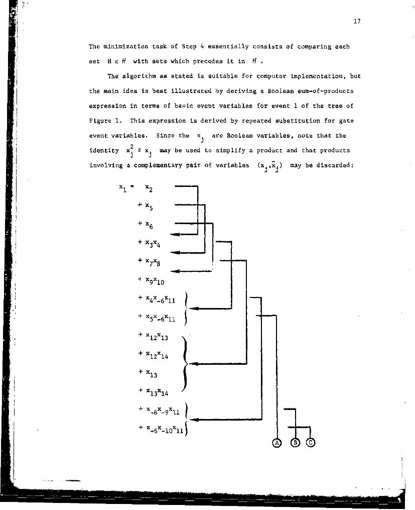
The algorithm as stated is suitable for computer implementation, but
the main idea is best illustrated by deriving a Boolean sum-of-products
expression in terms of basic event variables for event 1 of the tree of
Figure 1. This expression is derived by repeated substitution for gate
event variables. Since the x are Boolean variables, note that the
identity x xj may be used to simplify a product and that products
.1involving a complementary pair of variables (x ,X ) may be discarded:
+ X 5I+ x56
+x x3 4
+ x1 2 x1 4
+ x1 313 14
+-6 -gll x
+ x 6 X
~ ~~~~1 . .. ,14 , • i i i
18
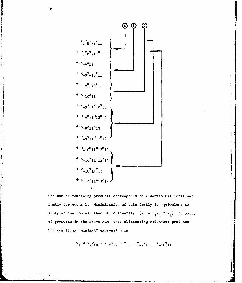
+ X7xXs-gl x "
,+X7 X8 x~lOXIl S+ X-9X l1
+ x- 9x- 1 0x 1 1
+ x 9x- 1xll-9 - 10 2 14
+ X xlx
-1 13+x x x x
- 11 12 13+ x_ x110x 12 xl4
+% x x lc
+x xxlX911 13 14
+ x_ 10 xllxl 3Xl
+ x x x
-10 11 13 14
The sum of remaining products corresponds to a nonminimal implicant
family for event 1. Minimization of this family is Ž,quivalent to
applying the Boolean absorption identity (xi + xxj xi) to pairs
of products in the above sum, thus eliminating redundant products.
The resulting "minimal" expression is
xI - xgX0 +X x + x + xg x + x_1X
910 12 14 13 -911 10 11

I19p|
MICSUP (Mtnimal Cut Sets, UPward) is an alternative method of
constructing basic event implicant families proposed by Chatterjee [3].
At least two computer codes utilizing this method are available [12],
[13]. The technique is based on Che observation that if minimal basic
event families I are available foa all immediate subevents j c Di
of a particular gate event i , then the minimal basic event family
for i is simply
m U cF-D(YiD) JE1
where I [{J}I if j is a basic event. To find a basic event
family for the top node event of a fault tree, say event 1, the
procedure is as follows:
0. F - f i} .
1. If all events i e F have been considered in this step,
go to 3. Otherwise select i c F not previously considered.
2. F + F U {j e Di .J a gate event}i
3. Consider successive elements of F in upward order (any
ordering such that each event follows all of its subevents).
For each i c F construct
ýI D(iD i) C J1l
Steps 0, 1, and 2 serve only to avoid, if possible, finding 7 and
I for every gate node u of a fault tree containing complementing-u
arcs; if the tree contains no complementing arcs, we may let F = G
the set of gate nodes, and just perform Step 3. Also, minimization may
Vi

20
be postponed until I is constructed if it is expected that the
unminimized families for immediate subevents of I will not constain
a large number of nonminimal sets.
For the example tree of Figure 1, this simple method is illustrated
with Boolean expressions. Evidently, the set F in its proper order
is (8,7,6,-6,5,4,3,2,1}
x8 '13 14
x7 x 12 + x13
x6 -x 9x 1 0
X ~X + X-6 -9 -10
x 5 7 8
S(x 12 + x 1 3 )(x 1 3 + X1 4 )
"" x12X13 + x 1 2 x 1 4 + x 1 3 + x13x14
"X 12 x 34 + x 13
x4 -x_ 6X1 1
= (x_ 9 + x-l0)Xll
X- 9 x 1 1 + X- 1 0 X 1 1
x X + x3 4 5
- (x_ 9x 1 1 + x 1 0 x1 1 ) + (X1 2 x 1 4 + x13)
" x 9x 11 + x- 10x 11 + X 12 x14 + X 13

21
x2 x3 x4
L- (x 9 x1 l + x_ 1 0 1X + xL2 Xl4 + X 3 )(X_ 9X1 1 + x 1 0 X1 1 )
" X~xl + ~g_!oll+, xX Xl2X49 X 9 1 1 + Xi] 19 11 12 14 1.
+X Xgx +x x_1 OX + X- o x-X9 11 x13 + -9 x-10 x11 + -10 x11
+ X 1 0 X1 1 X1 2X1 4 + X10X llXl3
- + X + X
x 1 x 2 +2x3 +x 6
- (x_ 9x1 1 4 x 1 0 X 1 ) + (x19 x1 + x 9 1 0 x 1 - X1 2 x 4 + 1 13
+ (X9 x1 0 )
SX- x + x- X +x x + x- x
+ Xl2X4 + X3 + XxgO+ 1 2 1 4 1~3 9 10
"X xXl + X- 0Xl + X12x4 + x3 + Xg0 •
The MICSUP algorithm is superior to MOCUS in two cases:
(1) when basic event families are desired for a number of intermediate
gate events as well as the top event, and (2) when only sets not
exceeding some given number of basic events are required in the top
event family. The second case is most important in practice. Often
the minimal top event family has many sets which contain a large number
of basic events. If the fault tree is free of complementing arcs,
each of these sets is associated with a mode of system failure due to
failure of a large number of basic node components and subsystems;
that the actual system will fail in this manner is highly unlikely.
Thus implicants which exceed some given size are usually not of interest
in the subsequent reliability analysis of the system. The convenience

22
of the MICSUP method in this case is a consequence of the fact that
sets generated for every gate event consist only of basic events, and
any set that exceeds a given size may be immediately discarded.
This way of finding a subfamily 7i of the complete minimal
family 71 for event i does not, in general, yield meaningful results
for fault trees involving complementing arcs, due to the fact that
is usually not a prime implicant family. However, as an illustration,
suppose that only products of size 1 are required in the previous
example. The expression following each colon (:) below results from
discarding products containing more than a single variable.
x 8 x1 3 + x 1 4
x 7 X 12 + X13
x 6 x9x 10:06 91 0
_6 +x_9 +x x +O
"(x1 2 + x1 3 )(x 1 3 + x1 4 ) : 3
X4 x 6_6 X1 1
" (x 9 + x1l)xl 1 : 0
x3 -x 4 + x5
- (0) + (x 1 ) :x
x2 X 3x4
- (x13)(0) :0
xl= x2 * x5 +x 6
=(0) + (X )+ (0) XS(x 3) 13

23
(A null expression for xi means that there is no basic event variable
which by itself implies xi .) In addition to x , x also implies
xI , so the method has failed in this case to find all single variables
that imply x. What is really desired here is the subfamily of
all prime implicants for event 1 which consist of only one basic event.
1.2.3 General Framework for Implicant Elimination
Implicant size is one criterion which may be used to determine a
subfamily of "interesting" implicants when the complete minimal implicant
family is too large to obtain. More generally, given any set of events
E , an importance criterion for E assigns certain subsets of E to
a class, called important sets, in such a manner that if I is
important, all subsets of I (ignoring the null set) are also important.
This definition just guarantees that if V' is a subfamily of all
important sets of the family I -then m[P'] C m[l] . Also, let f
he a reai-valued function whose domain consists of all subsets of E
it is convenient to call f an importance function if for any real
c either [I I I C E , f(I) < c! or [I I I C E , f(I) > ci is a
class of importait sets.
Suppose that a positive real value i(k) is chosen for each
event k E. If f(1) i(k) for each I C E ,then f iskF I
an importance function; if i(k) - I for all k c E , then all sets
not exceeding a critical size c are important. Many other importance
functions can be constructed using the i(') values, such as min t(k)kFl
or, when all values are between 0 and 1 , l(k)
kEI

24
For fault trees that do not contain complementing arcs, the
MICSUP algorithm obviously lends itself well to construction of
minimal subfamilies of all implicants that satisfy an importance
criterion, For E - B , as in the case of elimination by size,
implicants that are not important may be discarded whenever they
appear.
1.3 Simple Modules
Deleting nonminimal implicants of a family is unquestionably
the most time zonsuming task in MOCUS and MICSUP methods. Given an
arbitrary implicant family K in any order, m[K] is obtained
essentially by comparing each set K with all sets that precede it
in K . If J is a preceding set, K is eliminated if J C K and
J is eliminated if J D K . Some effort can be saved by ordering the
sets of K according to increasing size; then K is not strictly
contained in any preceding set. In any case, the number of set com-
parisons required to find m[K] , if K consists of n sets, seems to
2be bounded above by some constant times n
In practice, MOCUS and MICSUP algorithms often perform a great
deal of minimization that could be avoided by isolating certain branches
of the fault tree that have no basic nodes in common. Such is the
general idea underlying this section.
I -i. ..i • 1 • •.....1 --•/.. .. .i • ...i • i. .. ...i ...f.... ----....i.. ... .... ....i.....i...... .

25
1.3.1 Simple Module and Modular Subtree Definitions
We begin with some additional definitions regarding fault
trees. If node w is a subnode of u , a chain from w to u
is the set of nodes along an upward path from w to u . For
instance, in the tree of Figure 1, the sets (12,7,5,3,2,1) and
{12,7,5,1} are chains from node 12 to node 1. The number of nodes
in the largest chain from w to u is denoted by cu(w) , and
c (') is an integer valued function having u and the subnodes of
u as its domain (c (u) - 1 for any node u). In the example tree,
cl(1) - 1 , c(2) - 2 , cl(3) - 3 , c (4) - 4 , ci(5) - 4 , ci( 6 ) - 5 ,
etc.
Next, if v is a subnode of u , v is said to be a simpZe
module for u if every chain from a basic subnode of v to u
includes v . Node 5 is a simple module for node 1 in the example
tree, since the basic subnodes of 5 are 12, 13, and 14, and the
chains from these nodes to node 1 are [12,7,5,3,2,1] , [12,7,5,1]
[13,7,5,3,2,11 , [13,7,5,1] , [13,8,5,3,2,1] , [13,8,5,1][14,8,5,3,2,11 , and [14,8,5,11 , all of which include 5. It is
helpful to think of the Boolean variables associated with a simple
module as indicating the status of an independent subsystem; that
is, given the status of the subsystem, the status of any component
in the subsyscem is irrelevant to the.pzoblem of determining
whether the system itself is working. For instance, the values
of x 1 2 , x13 , and x1 4 are not important in determining the
value of x if the value of x5 is known. Note that with this
definition, node 4 is a simple module of node 3, but not of node 1,
S It• k I-

26
so the node or set of nodes must be specified for which a particular
node is a simple module. Also, for any gate node u , all basic
subnodes are trivially simple modules for u .
If node v is a simple module for node u and v is not
a subnpde of some other simple module for u , then v is a largeat
simple module for u . In Figure 1, the largest simple modules for
node I are 5, 6, and 11, whereas those for node 3 are 4 and 5.
It is easy to see that the largest simple modules for a node have
no subnodes in common, a fact which motivates these definitions.
The modular eubtree for a gate node u consists of all nodes,
along with the arcs joining these nodes, that appear in chains
from the largest simple modules for u to u itself. Node u
is thus the top node of its modular subtree. Figure 2 illustrates
the modular subtrees for nodes 3, 4, 5, and 6 of the example
tree. This definition of a modular subtree is related to the idea
of an independent branch of the fault tree, introduced by
Chatterjee [4].
,"1

27
4 5
4 5
6 78
Ii
6
12 13 14
9 10
FIGURE 2

28
1.3.2 Application of Simple Modules to Implicant Families
The above concepts may be readily associated with implicant
families. For convenience, call event j a simple module for event
i if node jl is a simpl.e module for node il in the fault tree,
and the modular subtree for event i is the one having node lil
at the top. Were the MOCUS or MICSUP method applied to the modular
subtree for event I , with largest simple modules for i treated
as basic events, the result would be a minimal implicant family Mi
in terms of these largest simple modules. More suitable algorithms
to find implicant families associated with modular subtrees are
discussed in Section 1.4, but for purposes here, nothing is lost by
assuming that procedures similar to MOCUS or MICSUP are available
to find families M
For a given set Q of gate events, a modular truzcture for Q
is a collection (M I of minimal implicant families in termsJ JE:M(Q)
of largest simple modules for their respective index events, where
the index set M(Q) is the smallest set satisfying (1) Q C M(Q)
Sand (2) if J is a gate event In an implicant of some family Mi
for i E M(Q) , then J e M(Q) . The modular structure for Q is
just the smallest group of implicant families in terms of largest
simple modules necessary to find a basic event implicant family for
each event in Q . For the tree of Figure 1, M({l}) - {1,5,6,-6)
and

29 "1• •~ M 1 - [ { 5 } , t 6 }, { - 6 , 1 1} ],
M5 - [[13},{12,141]
M6 - [{9,10}]
_6 - [{-9},{- I0}]
M-6
However, M([1,3}) - (1,3,4,5,6,-6) , so the modular structure for
(1,31 includes, in addition to the above families,
M3 - [(31,{41}1
M4- [{-6,ll}I
Reliability evaluations for a fault tree are usually introduced
by associating independent 0-1 random variables Xu (= 1 - X_u)
with all basic nodes u . For a gate event i , with a minimal
basic evn mplicant family 1ith ano variable X is taken
to be 1 if at least one set I e I has X - 1 for all j c I
,otherwise, X is 0 . Under the assumption of probabilistic
independence of basic node variables, variables for nodes that are
largest simple modules of any particular gate event are also in-
dependent, since they have no common basic subnodes. Hence reliability
evaluations for events j c M(fi}) may be done by considering these
events in upward order, and treating each family M as if it con-
sisted of basic events. The number of minimal basic event implicants
for i usually far exceeds the total number of implicants in all
modular structure families (M } •M {i }j J .(i )
- - -

30
Should basic event families be preferred for events in Q
they are easily obtained by selecting the events j e M(Q) in
upward order and constructing in the usual manner:
ij 4- U X I mMEM m M
where, of course, IM [{m}] for m a basic event. Because them
largest simple module events j have no subevents in common,
minimization is unnecessary. In terrs of Boolean expressions, the
modular structure for event 1 of the example tree yields,
x_ 6 x- _9 + X -10
x6 x xglx6 c9 +x1 0
x X +x910x5 -x 1 3 + x1 2 1 4
xl -x 5 +x 6 +x_ 6x1 1
( 13 + x1 2 x1 4 ) + (x 9xlc) + (x_9 + x-lO)Xll
K 1 3 + x1 2 x 1 4 + x91X0 + X-9X 1 + x_ 10X •
Size restriction may be employed when a MICSUP-type method is
applied to modular subtrees for events in M(Q) . These subtrees
should be devoid of complementing arcs. The family Mý in the
resulting collection (M}J will consist of all implicants
of M j that do not exceed the size limitation, and further elimina-
tion is done as basic event families I' are produced.

31
Of course, elimination based on an importance criterion for B
is also feasible when basic event families are constructed. For
j E M(Q) , a subfamily is then constructed which consiets of all
important sets of the complete family I However, it is useful
to have an importance criterion for the set of all events that
appear in at least one implicant of M. (Denote this set by E(Mj) .)
Elimination can then be done when the MICSUP method is applied to the
modular subtree for j . An importance criterion for E(M ) is
easily obtained from a criterion for B by declaring a set M C E(M.)
important iff the basic event family X I contains at least onenxMmmEM
important set. This is valid because the event sets E(Im) , m E M
are disjoint.
Such an importance criterion for E(Mj) is actually quite easy
to implement when real nonnegative values i(k) are available for all
basic events and an importance function f is given in terms of these
values. Suppose, for instance, that 0 < i(k) < 1 for k e B
and for I a set of basic events, let f(1) - n i(k) . ForkeI
j E M(Q) we construct the subfamilies M' in upward order, that
is, Mj is, constructed following all families M foK k a subevent
of j When the family M is constructed, for each gate event
m E E(M ) which is a largest simple module for j , a value t(m)
will be available from a previous computation unless M' - 0m
If the MICSUP method is applied to the modular subtree to find M'
then all sets generated will be in terms of largest simple modules
for J , and only important sets need be retained, where in this case
a set M is important iff M' 0 0 for each m c M and (2) (ifm
condition (1) hold&)

32
W t(m) > cmcM
for a fixed critical value c . When the family M' has been
found, if Mj 0 , i(J) is determined by the computation
max ( I (M)M•M' mcM /
For MI 0 i(, J(J) is left undefined. It is quite easy to show that
a set M C E(Mj) satisfies (1) and (2) iff there is a basis event
set I e X 7 satisfyingmEM m
RI (k) > ckcl
This scheme can also be employed to yield a more efficient
technique for size elimination than simply restricting implicants in
modular structure families to a fixed maximum" size. Let a(k) E 1
for each basic event k and let f be the importance function
defined for a set I of basic events as f(I) o o(k) . As inksl
the procedure above, when M' is constructed, relevant values a(m)
for largest simple module gate events m c E(M ) will be available
from earlier computations. A set M C E(Mj) is now considered
important iff (1) M' # 0 for each m E M and (2) (if condition
(1) holds)
a c(m) <cmnM

I33
for a fixed integer value c . From the family M' , if M! 0 0
a(j) computed as
in"i
For any set M c M' In this case, there is at least one basic
event set I c X I having no more than c elements. We callMC,
the parLicular criterion discussed in this paragraph moduZar size
import~ane.
1.3.3 k Method for Identifying Modular Subtrees
For an arbitrary gate node u , let G U L be the set ofu u
nodes in the modular subtree for u , where L consists of allU
nodes that are largest simple modules for u and Lu n0 G- 0 ; GS u u
is never empty, since u c Gu
Finding sets G and L is not difficult computationally.u u
The technique described here makes use of particular sets of
replicated nodes, nodes which have more than a single leaving arc;
for instance 5, 6 and 13 are the replicated nodes'of the Figure 1
tree. For any node v , let Rv consist of all replicated subnodes
of v , as well as v itself if v is replicated. The set of
replicated subnodes of v is just
U R ,
where S is the set of immediate Bubnodes of vv
' i i i i ;; i ; • • .. . .

34
The following procedure determines the set L of largestu
simple modules and the set G for an arbitrary gate node u
LSM
0. z 0 , T * {u) L ÷ 0 , G 4- 0u u
1. If T 0 0 , stop. Otherwise z ÷ z + 1
T+ {v I v c T , Cu(v) A z) U (S I v c T c, e (v) - z
GU v Gu U v ) v e T c - z} R
L 4- L UL, T 4- T - L . Go to 1.Su uI
iI} As an illustration, we find the largest simple modules of the top
node of the tree of Figure 1:
LR4 U RL2, , T , - 0RI3 , R, R R13
R - {61
R 5 -{5,13}
R4 {4,61
S3 , 2 ,R1 (4,5,6,131

35
z 0 T G (1} L ÷ 0
z - 1 T 0 0 U {2,5,6}
G 0 U (1i
L 0
z 4 2 T { (5,6} U (3,4}
CL ÷ {1} u (21
L+0
z + 3 T - (4,5,61 U (4,51
G1- {1,21 U (3}
L (51 (since R5 n (R4 U R6 ) -0)
L1 0 U {5}
T - {4,5,6} - (51
z + 4 T {6} U (6,11}
- {f,2,31 U {4}
L { (6,111 (since R - 0)
L= {5} U {6,111
T + {6,111 - 16,11}
Stop.
Essentially, the method proceeds down the subtree with top
node u , and the set T and L involve nodes successively further
from u with increasing z . An examination of Step 2 shows that
if v is a subnode of u , unless v is a subnode of a largest
simple module for u , then v will eventually appear in the table
II

36
T formed in Step 2 for some value of z , say z' . If
Z' 0 c (v) - 1 then v is retained in each T for successive
values of z - z',z' + 1, ... , c (v) - 1 . When z - c (v) -1u U
in Step 3, then v is tested to see if it is a largest simple
module for u . If it is, v is included in L and removed from
T ; otherwise, S replaces v in the next T formed in Step 2V
(for z - c (v)) and v is included in Gu u
The validLLt:y of this procedure is based on the following easily
established facts:
1. Given any two fault tree gate nodes v and w neither
being a subnode of the other, then Rv n R 0 if and
.1 only if v and w have no basic subnodes in common.2. For any z , T U Lu contains at least one node of everyUL
chain from a basic subnode of u to u itself; moreover,
for each v e T and w L , Rv Rw -0
I; 3. For v E T , z - c (v) - , there is no w e T such thatU
v is a subnode of w
4. For v c T , v a simple module for u , there is no
w e T such that w is a subnode of v
An effective method of constructing the set L in Step 3
deserves mention. Let r - (rI, ... , r ) be a vector having the
same number of components as fault tree nodes. The set T is taken
to be ordered in some arbitrary manner and for v , w E T we write
v -- w if v precedes w in T . Node u is again the subtree
top node.

37
1r
0, L -0 . For each w E R , r - 0 in r
1. If all nodes of T have been considered in this step,
stop. Otherwise select the next element v e T in the
order ,
2. If z c u(v) - 1 , go to 3. Otherwise, if rw - 0 for
all w r R v , then L 1 L1 U {v}
3. r 4 v for all w e R . Go to 2.w v
This procedure constructs the set
L Ivi v e T , c (v) - z + 1 , and R flR -0 for all w -v in T}.U w v
The same procedure may be applied with the modification that the
elements of T be considered in reverse order to obtain
L (v v T , c u(v) - z + I , and R% i Rv 0 for all w -v in T}.
1 2. Then L L LL
We sometimes require that the largest simple modules be known for
each gate node of the fault tree, so the LSM procedure must be applied
for every u P. G .'However, calculating c u(w) for all subnodes
w of u for each u c C is wasteful, and a more efficient method
can be suggested. This method is motivated by two simple facts:
First, if G and L are available for some gate node u , andu U
we wish to find Gv and L for some v e G ,then it is onlyvv u
necessary to calculate c v() for subnodes of v in G U L ,s u u
since Gv U Lv C Gu U Lu . Secondly, if v is any gate node which
V v u
i __ _.____.____,____,_

38
is a simple module for u then c (w) c (w) - c (v) for any
subnode w of v . In the following statement of the method, it
is assumed that a downward order has been determined for the set
G of all gate nodes.
MODS
0. For all w c G, N G U B.w
1. If all nodes in G have been considered in this step,
stop. Otherwise, select the next node u e G in downward
order.
2. If L and G have been found, go to i. Otherwiseu U
calculate c (.) for all subnodes of u in N , andu u
M + {u}
a. If L and G have been found for all nodes v e M
go to 1. Otherwise select v c M for which L and
G are not available.v
b. Find Lv and G using LSM procedure, noting that
either v E u or v is a simple module for u , so
cv (w) - c (w) - Cu (v) for all subnodes w of v
C. M - M U (w I w e L , w a gate node} . For each
w e G - {v} for which G is not available,v w
N - G U Lv . Uo to 2a.
Note that substeps 2a thru 2c are repeated until all simple modules
have been found for node u chosen in Step 1.
The process of determining largest simple modules for each
gate node of the tree of Figure 1 is illustrated:

39
N w {1,2,3,4,5,6,7,8,9,10,11,12,13,14} , w C Gw
Calculate cl() for subnodes of node 1 in N1 M ÷ (i}
L1 {5,6,111 G1 {1,2,3,41
M + {11 U {5,61
N f1,2,3,4,5,6,11} , w e (2,3,4}w
L - (12,13,140 , G- (5,7,8}55
N + (5,7,8,12,13,141 , w E {7,81w
L6 - {9,10} , G- {61
Calculate c 2 (') for subnodes of node 2 in N2 . M ÷ (2} .
L2- {4,51 , GO2 {2,3)
M + (21 U {4,5}
N3 + (2,3,4,51
L 4 - {6,11} , G 4 -{41
] M ÷{2,4,51 U {61
L5 , G5 found previously
L6 , G6 found previously.
Calculate c3 (.) for subnodes of node 3 in N3 . M + {31
53- {4,51 , G3 - (3)
M {31 U {4,5}
L4 G 04 found previously
L5 , G. found previously.
5~
40
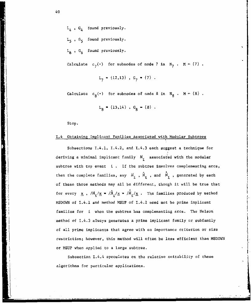
L 4 , G4 found previously.
L5 , G5 found previously.
L6 , G6 found previously.
Calculate c7 () for subnodes of node 7 in N7 M [ (7)
L 7 { 12 ,13} , G (71"f7
Calculate c 8 (.) for subnodes of node 8 in N8 . H + {81
L8 {13,14) , {8- 8
Stop.
1.4 Obtaining Implicant Families Associated with Modular Subtrees
Subsections 1.4.1, 1.4.2, and 1.4.3 each suggest a technique for
deriving a minimal implicant family Mi associated with the modular
subtree with top event i . If the subtree involves complementing arcs,
then the complete families, say Mi I Mi , and Mi , generated by each
of these three methods may all be different, though it will be true that
for every x , /M - /xi/x U /Mi/x . The families produced by method
MSDOWN of 1.4.1 and method MSUP of 1.4.2 need not be prime implicant
families for i when the subtree has complementing arcs. The Nelson
method of 1.4.3 always generates a prime implicant family or subfamily
of all prime implicants that agree with an importance criterion or size
restriction; however, this method will often be less efficient than MSDOWN
or MSUP when applied to a large subtree.
Subsection 1.4.4 speculates on the relative suitability of these
"algorithms for particular applications.
.u ..! !

41
1.4.1 The MSDOWN Method
The spirit of this method (Modular .Subtree Downward) is akin
to that of MOCUS, but MSDOWN is more intricate and more efficient
for most applications. The algorithm makes use of the concept
presented in Section I.1 of the dual of a family of sets of positive
and negative integers. For purposes here, this concept requires some
additional comment, which is introduced by way of an example.
Consider the fault tree of Figure 3. Were the MOCUS algorithm
applied to this tree, the process of constructing the minimal implicant
family T would be represented by (with Z. M 1)
m[ X D(VZeDe)]ee{2,3,4,5}
where D2 - {6,7,8,9} , D3 - (7,8,-9,10} , D4 - {7,8,11,121 , and
D5 -9,10,13,14) . In a Boolean context, the state vector is
x (x 1 ,X2 , ... , x14 ) , and the expression for / X V(I,D )/xI' ee{2,3,4,5e
is a product of sums,
(x6 + x7 +x8 + x9 )(x 7 +x8 + x_ 9 +x 1 0 )(x 7 + x 8 +x 1 1 + x1 2)(x 9 +x 1 0 +x 13 + X14)•
So determining the product family and minimizing is essentially
equivalent to expanding the above expression into a sum of products
and eliminating nonminimal products, as well as products having comple-
mentary pairs of variables. Of the 256 products, 228 have no comple-
mentary pairs of variables, but only 16 products are minimal.
Though the tree of Figure 3 is contrived, and such trees do not
often occur in practice, the point is that if an implicant H with

42
z 4
F 3
I FIGURE 3

43
a moderate number of gate events appears at some time during applica-
tion of the MOCUS procedure, the product family X D(2eD ) may beecH
quite large, especially for a tree where a sizable proportion of the
Z are 1 (OR relations). However, the family remaining aftere
minimization may be relatively small if the immediate subevent sets
De involve events associated with replicated nodes. This suggests
that siibstantial effort could be avoided if the family
:1m V(Ze ,De)]m [eeH eej
could be found without generating all the nonminimal sets in the
product family.
From the definition of the family V(2eDe) , it is clear from
Section I.1 that d[(e,D)] 9 D(#D - t + , where #De e e e e e
is the number of elements in De Moreover, d[d[V(k e,De)]]e e
(e,De) D Thus by Proposition 1.1.3,
d UV(#D e, m [X (eDc)]
The family in brackets on the left requires about the same amount
of effort to construct as the families (X ,D e) together. The
algorithm given in Reference [17] finds the dual of an arbitrary
family F and is well suited to our purposes here. Essentially,
the algorithm generates the sets of d[F] in groups, and minimization
is required only among members of the same group; in fact, when finding
the dual of U V(#DD - k. + 1,D ) the algorithm bypasses minimiza-
eiH e e e
tion altogether if the sets De , e c H are pairwise disjoint.

44
In addition, the number of nonminimal sets appearing during con-
struction of this dual will always be less than the number of such
sets in X D(G eSe) usually many times less. Use of the dualeCH a
algorithm in the manner suggested here to find I for the tree of
Figure 3 requires only 1/10 the compucation time necessary to
produce and minimize the product family. The difference in efficiency
between the two methods becomes increasingly dramatic as the number
of sets in the product family increases. It is not hard to devise
examples where the dual algorithm generates the required minimal
family quite easily, but formation of the product family is computa-
tionally impossible.
If X D(Z ,D ) is small, say fewer than 20 sets, the dualeH e eeEH
algorithm may require somewhat more computation time than forming
and minimizing the product family, due to the comparatively large
amount of computer code associated with the algorithm. However, in
this case, the computation time required by either method is quite
negligible; so in the MSDOWN method, it is not worth the trouble to
bypass the dual algorithm and derive and minimize the product family
whenever this family has fewer than 20 sets.
The steps below comprise the MSDOWN procedure applied to a
modular subtree with top event i . The procedure requires that the
set L of largest simple modules for u - Il be available, asU
well as the set G of subtree nodes which are not in Lu u
ij4

45
MSDOWN
0. z 0 , -o , ua- Iii , H [til1
1. z + z + 1 , CZ {v I v C G , c (v) - z)u u
Rz -4-fv gc¢.GO U L , cu(V) inz +J. , v replicated}.i
If C2 - 0 M - H and stop.
2. If all H E H that intersect Cz U (-Cz) have been
considered previously in this step, go to 5.
Otherwise, select H c H with H n (Cz U (-CZ)) 0 0
that has not been considered.
3. a. For each e c H if e e Cz U (-C2 )
J * V(#D - 2e + l,De) , and if e Cz U (-Cz)aj e e e
4- [(el]e
b. a +•+ 1.
c. H +d U Je]
d. H - [H- [H]] U Hk , go to 2.
4. R + [H H H , H n (Rz U (-RZ)) # 0]
(R will thus contain all H having a replicated
subevent e with c (Jel) - z + 1 .)u
5. Partition sets of R into disjoint families {R a 1,I
where R - R r) H and A consists of all c such
that R 0.
6. H (H - R] U A m u R] go to l.
Following each execution of Step 1, events e c H for any
implicant H E H all satisfy c (I el) > z . Steps 3a thru 3d
select each implicant H E H having at least one event e satisfying
c (l el) z and replace this implicant with a family Hn

46
For e c H if we let J u(#D e + 1,D for c(lei) z' " D(#e - e + 'e) fo c(
and J - [[e)] otherwise, thene
Ha "m [eX Je]e
by our earlier remarks. Thus when Step 4 is begun, events e F H
for any H c H have c (lei) > z . At this point, the population
of events e with cu(Iel) - z + 1 is greater than in all families
H previously constructed, since no substitution for these events
has yet occurred. The events which correspond to replicated nodes
of the subtree and satisfy cu(lei) - z + 1 are likely to be found
in nonminimal sets of' H . So we aasign sets containing such replicated
events to the family R ,and minimize only this portion of H.
Moreover, for any family H constructed in Step 3, the intersection
of H and R is minimal (though it may he empty), because H isOL a
minimal. Each family of the partition in Step 5 is thus minimal, so
the indicated minimization only requires comparison of each set of a
family R with all sets in preceding families.
It is intuitive but not obvious that the minimization scheme in
this algorithm insures Mi will be minimal. This is the case, but
to establish this face rigorously is tedious and not particularly
instructive, so we do not consider the proof.
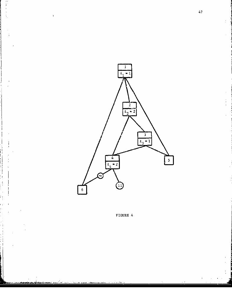
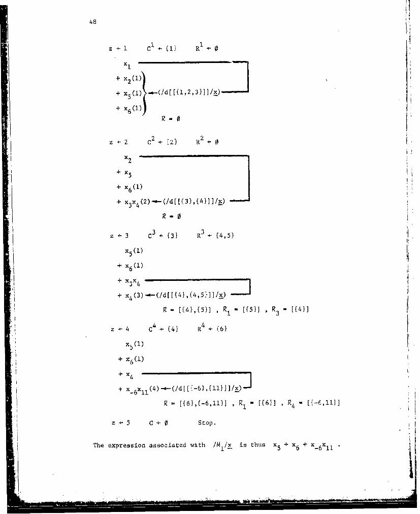
Figure 4 shows the modular subtree for the top node of the
Figure 1 tree. The following example derives the minimal implicant
family M1 for this subtree using Boolean variables. The integer
in parentheses following a term is the value a associating the
corresponding implicant with the family H The families R of
Step 4 and those of the partitions of Step 5 are also indicated.
47
2
9£2 ~2
FIGURE 4
- - .- '~i
48
z+÷1 C {I1÷{} R
+ x2(1))
+ X6(J) -
+ x6()R-
SC 2 {2} R2 ÷
x2
+ x5
+ x6 (1)
+ x3 x 4 (2)*-(/d[({31,{41}]/2_)
R? 0
z .3 3 ({3} R3 (4,5} 1'
x 5(l)
+ x6(1)
+3
4
+ x4 (3)- -(/d[[{41,(4,5}11/x) __j
R - [{4},{5}] , R1 [{5}] , R ([{4}]
z +4 C4 {4} R4 - (6}
x5 (1)
S~+ x61
+ x 6X1 1 (4)-4--(/d[-6},tll}]/_)
R [{6},{-6,11}] , R [f6}] R4 - [{-6,14]
z 4- 5 C - 0 Stop.
The expression associated with /MI/x- is thus x5 + x 6 + x- 6X '1 '

49 '1
1.4.2 The MSUP Method
The MSUP algorithm resembles MICSUP confined to a modular subtree.
MSUP is particularly suited to applications where only a subfamily of
important implicants or those not exceeding a fixed size is required
for the subtree with top event i , rather than a complete family Mi ' A
1As with MSDOWN, the MSUP method utilizes the set L of largest
simple modules for the subtree top node u - Il , as well as the
set G of subtree nodes not in L . In addition, MSUP requiresU U
that sets L be available for all v e G ; thus, prior to derivingv u
the modular structure families {MJ jcM(Q) using MSUP, it is con-
venient to apply the MODS algorithm of Subsection 1.3.3 to determine
the largest simple modules of every fault tree gate event. Finally,
MSUP calls on a "downward" type subalgorithm designated as ORDOWN
(substitution for OR-relations, DOWNward). Since ORDOWN has much in
common with the MSDOWN method of the previous subsection, we first
discuss this subalgorithm.
ORDOWN, like MSDOWN, obtains an implicant family N. for jJ
a top event of a modular subtree. However, the events in implicants
of the family N need not correspond to largest simple modules for
the subtree top node v JI . The method is outlined as follows:
ORDOWN
0. a + 0 , v - 1JI , H + [(j}]
1. C (v} u {w I w C Gv , w l}
2. If all H c H that intersect C U (-C) have been considered
previously in this step, go to 4. Otherwise select H E H
with H r) (C U (-C) # 0 that has not been considered.
"--• i•- } •i i -• ' • - n - i

50
3. a. For each e e H , if e e C U (-C)
J D(#D - ke + lD) , and if e L C U (-C)
J 4- [fe)]e
b. a. +•÷l.
c. H d e H
d. H ÷ [H - [H]] U H and go to 2.
4. Partition sets of H into disjoint families H - H n H and
let A consist of all a such that H a 0
5. N. m UaA HmI and stop.
Note that each H is minimal, since H arises from a singlea a
application of the dual algorithm; thus, the minimization in Step 5
involves comparing sets in H only with sets in preceding families
of the union.
The form of this method is somewhere between MOCUS and MSDOWN,
but its important feature is the set C of Step 1 which controls
event, substitution in implicants of H . Substitution for the top
event 1 is always done, but a subsequent event e appearing in sets
of H that is not a largest simple module for j may only be
replaced by D( eDe) if Ze - 1 , that is, if x is represented
by an OR relation between immediate subevent variables. One effect
of this restriction is that no set of the family N1 will contain
more events than a set in the top event definition family, V(j,%D)
though N1 will usually contain more sets than the definition family.
A second effect is that events in implicants of N. are more likelyt
to correspond to largest simple modules for 4than events in Dj
/.1
• -,... ....... .. . ... ..... ..i ...... i ........ .. .. .... ..i ...... ..... i .............. .... ..i ... ........ i........ i........ ... .. . ...... ... .... ...... ... .... .. . ... ............ ..... ... ..

51
though it may happen, of course, that N and D(ZJ,D ) are the
same. The motivation for producing families Nj for selected gate
events j of the modular subtree will be discussed in connection
with the MSUP method.
For a large modular subtree with top event J , sets of N
will usually involve only events for nodes near the top of the subtree,.i
and in such a case, it is to be expected that N will contain
many fewer sets that the family M produced by the MSDOWN method.
For this reason, the more elaborate minimization scheme of MSDOWN
has not been included in ORDOWN. However, MSDOWN can be modified
to produce the family Nj instead of M by changing the formationZj
of the set C in Step 1 of that algorithm.
For event 1 of the Figure 1 tree, ORDOWN proceeds in this
fashion:
C {1,3}
X 1
+ x
H HI - [{2},[5},(6}1
Stop.

52
The expression associated with IN /x is x2 + x5 + x Hence,
for this example N1 - D(ClpDI) But for event 5, ORDOW14 gives
/N5/x as x 12x14 + x
To find the minimal family Mi in terms of largest simple
module for event i , the steps of the MSUP algorithm are as follows:
MSUP
0. F i i•
1. If all events j e F have been considered previously
in this step, go to 4. Otherwise select j e F not yet
considered.
2. Determine the family N by applying algorithm ORDOWN
to the modular subtree with top event j
3. F + F U {e I e E E(N ) , e not a largest simple module for i.
Go to i..
4. Consider events j e F in upward order (so any event of
F follows its subevents), constructing families K in
this manner: If all events in E(Nj) are largest
simple modules for j
K 4- U x KNeN1 neN
where K ({n}] if n e L . If not all events inn U
E(Nj) are largest simple modules for j
K1 -4- m [U x~ K]NeNj nE:N
5. M i Ki and stop.
~ ~ ~ - . ,i ii ii i

53
E(Nj) appearing in Steps 3 and 4 is the set of all events appearing
in at least one implicant of N Also, though the facility for
implicant elimination based on an importance criterion or size
limitation has not been included in this outline of MSUP, elimina-
tion may be carried out in Step 4 just as indicated in Subsections
1.2.2 and 1.3.2 with regard to the MICSUP method.
The families K generated in Step 4 are all in terms of
largest simple modules for event i In fact, if in Step 2 the
ORDOWN procedure is ignored and N D(ZJDj) , then the resulting
method is the MICSUP procedure applied to the modular subtree for
event i , with the exception that information concerning simple
modules guides minimization in Step 4. The incentive for obtaining
N from the ORDOWN algorithm is threefold: First, sets of N are
more likely to contain only simple modules for j than sets of
D(kjD) , so there is less likelihood that minimization will be
required when Kj is constructed. Secondly, since we are ultimately
interested in the implicant family Ki (- Mi) , construction of
implicant families for other events in the subtree for event i should
be avoided I.f possible. Use of ORDOWN usually leads to a smaller set
of events F at the beginning of Step 4 than if N were set to
D( D ,since an OR gate event e E , not a simple module for
some other event in F , would not appear in F . Finally, the sets
of N are no larger than those of V(jDj) so implicant elimination
based on size or importance in Step 4 is no more difficult than in
MICSUP.

54
For event 1 of the tree of Figure 1, repeating Steps 1, 2, and 3
of MSUP yields families N, N2 and N4 represented by the Boolean
expressions:
X1 x2 + X 5 + x 6
x 2 X4x2 -x x
x4 - 6X 11
The set F (in proper order) is (4,2,1Y Since 4 is a simple
module for 2, minimization is only done when M is found:
x4 - X_ 6 x 11
x 2 ' X4
W X- 6 x11
X I x- 6X1 1 + X 5 X6

55
1.4.3 The Nelson Method
Associated with any given fault tree is a dual tree, which
differs from the original, or primal tree, only in the value of
gate node logic indicators. If Z is the logic indicator for node
u of the primal tree, then #D - Z + 1 is the corresponding logicu u
indicator for the same node of the dual tree. Of course, for trees
having only AND and OR logic, the dual tree is easily obtained from
the primal by changing each AND gate to an OR gate and vice-versa.
Since the defining families V(ZuD ) and (#Du - z + ],D 'u u u
for gate event u of the primal and dual trees, are dual families,
Proposition I.1.1 of Section I.1 indicates that for all x
/D(#D - Z + 1,D )/(1l-x) - l-/V(Zu D )/x
U u U u -
This holds for all u £ G , so for any vector x consistent with
the primal tree, in the sense of Section 1.2, the vector 1 x
is consistent with the dual tree; that is, for all u e G ,
ID 0D- z + l,Du)/(l-x) l-xuU U u
Were the MSDOWN (or MSUP) method applied to the modular subtree for
event i in each of these trees to obtain a family Md for the dual treei
and a family Mi for the primal, then for all x consistent with
the primal tree it would be the case that
/M /(d-X) 1-/Mi•xi i

56 jSo again by Proposition I.1.1, the dual. family, dEM] , associated
with Md would satisfy, for all x consistent with the primal tree,
£d
/ IMpraXtreeX
Thus we see another way to construct a minimal iirplicant family Mi
from the modular subtree for event i Apply the MSDOWN (or MSUP)
algorithm to obtain a complete minimal family for the dua
modular subtree for event i , and then construct the dual family,
d ,associated with MI
This procedure may not always be successful in practice. The
first problem involves obtaining M ; this may not be possible if
dthe muodular subtree for i is large, since M muse be a complete
minimal family, and a subfamily of important or size restricted sets
is not adequate. Secondly, even when Md can be generated, con-i
struction of d[] may be difficult. There is a well-known argument
that a "good" algorithm for finding the dual family for an arbitrary
family will probabily never be devised [1], [15]; a "good" algorithm
would be such that the effort required could be bounded in all cases
by a fixed polynomial in the number of sets in the dual family or
the number of elements composing these sets. This, however, is not
intended to suggest that all algorithms for constructing dual families
are equally "bad."
The dual algorithm given in [17] and previously recommended for
use in MSDOWN and ORDOWN methods has worked well for obtaining dEM1
in a number of applications, some involving quite large modular subtrees.
This algorithm also permits set elimination based on importance and
__ --- & -- I

57
size criteria to be utilized to considerable advantage in constructing
dasubfamily of all important sets of d or thoue not exceeding
a fixed size. In fact, if the complete family Md is available,
adequate size and importance restrictions can almost always be chosen
Sthat some subfamily of dMd will be found with a moderateKI I
amount of computational effort.
In some instances where this method has been applied to large
dsubtrees, the process of obtaining M and then implicants of±
d[7Vd] not exceeding fixed size has proven to be several times faster
than employing the MSUP algorithm to find the family M' with the
savae size restriction. These example subtrees did not contain
complementing arcs; thus, in each case the subfamilies generated by
the two methods were the same. One subfamily involved 1000 sets,
so the difference in effort required by the two methods can be
significant. However, it is well to note that families Md for the
dual subtrees all had less than 50 sets, though some of these sets
consisted of more than 25 events.
When the modular subtree for an event i contains complementing
Sddarcs, d[IA., ] will usually not be the same family as that produced
by the MSDOWN or MSUP method. For instance, Ml - [(5,6,11}] for
event 1 of the example tree of Figure 1, so d[Md] [5},{6j,(llj]
which differs from M1 - ({5},{6},1-6,11}] obtained by MSDOWN and
MSUP. The family djMjJ is a prime implicant family for the Boolean
function /({5},{61,(-6,J1l}1/ so d 1~ is a prime implicant family
for event I in the sense of Subsection 1.2.1. The method suggested
here may be recognized as an adaptation of "Nelson's Algorithm" [1l]

for finding a prime implicant family for the Boolean function IF/
given an arbitrary family F of subsets of U U (-U) (where U
as usual, is some set of consecutive positive integers, say
(i, ... , q}). It turns out that P - d[d[F]] is the required family.
One way to{-prove this is to show that d[F] is a prime implicant
family for the function /d[F]/ , which can be done by demonstrating
that if there is a proper subset of some P c d[F] such that this
subset implies /d[FI/ , then there is an x - (x, ... ,x q) such
that both /d[F]ll - x - 1 and /F/x - 1 , contradicting
Proposition 1.1.1. Our version of this technique is to findd
d[d[Mi by replacing d[Mi] with the minimal family Md obtained
through application of MSDOWN or MSUP to the dual modular subtree
dfor i . Though in general Mi , d[Mi] , it is true that
d[]- d[d[MiII
Letting P. represent the prime impli~ant for event J in
terms of largest simple modules for j , the collection (PJ}j I (Q)
may uow be derived by utilizing the Nelson method when the modular
subtree for j involves complementing arcs, and any one of the
methods MSDOWN, MSUP, or Nelson when complementing arcs are absent.
Suppose families in terms of basic events are generated in the manner
of Su-section 1.3.2; that is, events j E M(Q) are considered in
upward order and each basic event family I is generated by
I;U xpepj Pell P

59
Intuitively, it would seem that these basic event families should
also be prime implicant families, and this is in fact the case.
Also, since the dual algorithm is capable of constructing a sub-
family P~ consisting of all sets of d [Md] satisfying a size
or importance restriction, the remarks of Subsection 1.3.2 extend
"in an obvious way to fault trees with complementing arcs. Thus a
collection {P'} ot subfamilies may be obtained such that P'1jEjM(Q)j
is a basic event subfamily of all important prime implicants or those
not exceeding some fixed size.
To conclude this subsection, we note that the efficiency of
finding a prime implicant family in the manner suggested by d[d[F]]greatly depends on the particular technique utilized to construct
dual families. Sometimes the name "Nelson's Algorithm" is applied to
a detailed procedure, also called the method of double compLementa,
which is not noted for being very efficient. This procedure begins
with a Boolean expression in sum-of-products form, for example,
x x+ Xx +x X1 +X2 x 3x 4 3 4
The expression is complemented and, using DeMorgan's Law, converted
to a product of sums:
(x1 + x2 )(x 2 + ý3 + x4)(X3 + x4 )
Next, a sum of products is obtained by expanding and eliminating products
which are not minimal or contain complementary pairs of variables:
X 1 ix 2x4 + x x3 +xX13 2x3
,U,

60
This last expression is again complemented, repeating the above
steps to yield
X 1X 2 + xIx 3 + 2x.I + 4X3
In our notation, P - [[l,2},{l,3},{-2,3},{3,-4}1 is then a prime
implicant family for the function /F/ , where F - [{l,2},{-2,3,4},
(3,-4}]
The effort required by the double complement method increases
very rapidly as the size of F increases. Hulme and Wurrell (8]
considered the following sum of twenty products:
X1 X6 X7X9 2 7x2x x8 + 1 3 4 6 + 6 7a
+ X1 X 4X5 x 7 + x 3 x 4 x 7X8 + x 3X 6X8 X9 + x1x2 3x9
+ x1X 3X6x9 + x x2x4x + x XX3X7X9 + x1x3X6x8
+ x x x x + Xx x x + x X4XsX + x x x63 4 79 7 8 9 2 4 57 2 36 7
+ x x xx-x ; +-+ l + xx + xx2 3 79 1l-1 8 9 2 X 3 6X 9 3 378 9
, They terminated the double complement method after more than 6000
"seconds of CPU time on a CDC 6600 computer without obtaining the
prime implicants associated with this expression. Uqing a general
factorization scheme, they were able to find the 87 prime implicants
in about 400 CPU seconds.
This sum-of-products expression can be represented as a fault
tree in the manner indicated by the introductory example of Subsection
1.4.1 (Figure 3): Subscripts of expression variables are associated
with basic nodes, a separate gate node with AND logic is created for .1

61
each product, ind the top node is an OR relation between these gate jnodes. The MSDOWN method then essentially finds Md by applyingtop
the dual algorithm to a family F of twenty sets, where each set
is composed of variable indices in one of the above products, so
d[M,] is found by two major applications of the dual, algorithm.
The FTAP program, implemented on a CDC 6400 computer (which is
roughly comparable in speed to the CDC 6600), required less than
6 CPU seconds to find the 87 prime implicants.
1.4.4 Comments on the Choice of Method
The question naturally arises as to which of the three methods
of this section is "best" for a particular modular subtree. When
the subtree Is small, say fewer than 2u gate nodes, these methods
will not Fften differ widely in computational efficiency, and any
of the algorithms is appropriate, unless the subtree has complementing
arcs, in which case the Nelson method is usually preferable because
it produced a prime implicant family. On the other hand, when the
subtree is large, say more than 50 gate nodes, it is usually difficult
to predict the relative efficiency of these methods. The analyst may
have to rely-on trial and error or previous computational experience
with similat subtrees, combined with a few general considerations
discussed hi're.
Let us, first assume that the modular subtree contains no comple-
menting arcs. MSDOWN or MSUP will most likely be selected in this
case. MSD9)W1N is intended for use when the comp.Lete minimal implicant
family i is required, and is apt to be more suitable for this
purpose than the MSUP method, especially when a moderate or large
t1
L-, -, ~ ~ . --. ~ - - -

62
number of replicated nodes are somewhat evenly distributed throughout
the subtree. The general "downward" method, as well as the dual
algorithm incorporated with MSDOWN, then offers some protection
aga.Lnst the sudden appearance during processing of an unmanageable
number of nonminimal sets. However, if the subtree contains a small
number of replicated nodes, MSUP may be the faster of the two methods
for finding the complete family, but the difference in efficiency
will probably not be dramatic. MSUP, of course, is primarily intendedfor use in deriving a subfamily of Mi consisting of important or size
restricted sets.
The Nelson method may seem superfluous for a subtree without
dcomplementing arcs, but when the complete minimal family Mi for the
dual modular subtree has significantly fewer sets than the primal
family Mi , this method is apt to surpass MSDOWN or MSUP. Of course,
for the Nelson method to be successful, it is first essential that' d
MSDOWN (or MSUP) be capable of finding M. One clue that suggests
qd might be small is a predominance of subtree gate nodes with OR I
logi:. A more formal approach is to calculate rough upper bounds
d6 1.and 6 called subtree binary indicated imp Zi cant counts, on the
number of sets in Mi and Md ; a simple procedure for computing aii
and 8d is given below. For subtrees without complementing arcs,i
Sand d are the same as counts of binary indicated cut sets and
bNnary indicated path sets defined by Chatterjee [3], as long as the
modular subtree is treated as an independent fault tree in the latter
definitions, with largest simple modules for the subtree top event
representing basic nodes. As a first approximation, it is usually
-dd

63Ici d
reasonable to suppose that d3 exceeds the number of sets in Mi
by one or maybe two orders of magnitude. When the complete family
M caiL be generated, it: may be feasible to find all of the implicantsi
of d [Md] or perhaps only those satisfying an importance or size
constraint. The Nelson method, with size or importance elimination
denabled when applying the dual algorithm to Mi , can be coIAsiderably
faster than the MSUP method for obtaining the desired subfamily.
Quantities u and a3 are defined for a modular subtree with
top node u ; for i - +ij or i - -u ,For generality,
we allow the subtree to contain complementing arcs. Suppose che MOCUS
and MICSUP methods, as discussed in Subsection 1.2.2, were modified
to inhibit minimization. If then applied to the modular subtree,
with largest simple modules for u treated like basic events, both
methods would produce the same nonminimal family B or B inu -- U
terms of largest simple modules for u . Families B and B areu -u
called subtree binary indicated implicant families. Fortunately,
the number of sets in these families is easy to compute without
deriving the families themselves; 1 and B are these counts.u -U
When the modular subtree involves no complementing arcs, M
and M are unique prime implicant families, with M C B and-U u - U
M-u C SBu , so 1u and 3u are upper bounds for the number of sets
in M and M . Moreover, in the absence of complementing arcs,u -u
che families M and Md associated with the dual subtree are
ldalso unique, and for i - +u or i - -u , M can be obtained from
Mi by replacing each event j in an implicant of M_. by its
complementary event -j Thus B1 is also an upper bound on the

64 1
size of Md . On the other hand, when the modular subtree contains
complementing arcs, the family Mi determined by algorithm MSDOWN
or MSUP is generally not a prime implicant family for i , and it
cannot be argued that M, S B, . However, for all practical purposes,
it will very rarely be the case that the number of sets in M iIexceeds the number of sets in
Quantities 1 and B are determined by the following rapidu -U
procedure: For each node v that is a largest simple module forthe subtree top node u 13 ÷ 1 and 1. + 1 . Consider nodes in
V -v
G , the set of subtree nodes that are not largest simple modules,
in upward order. For v e Gu
1v k
KEV(Zv,Dv) kEK
Kr:V(#Dv-k v+l,D_v) kFK
The last values calculated are 6 and 1S~U --u
Finally, a few comments should be directed toward application
of MSDOWN, MSUP, and Nelson methods to subtrees which contaiti comple-
menting arcs. The workload for each algorithm is about the same
as when complementing arcs are absent. However, the complete
implicant family Mi produced by MSDOWN or MSUP is no longerli
guaranteed to be a prime implicant family for i . For some fault
tree applications, this may be acceptable, or the analyst may wish
to obtain Mi and from it generate a prime implicant family by any
of a large variety of prime implicant algorithms available in the

65
literature; for example, see [14]. of course, implicant elimination
based on size or importance should not be used in conjunction with
MSUP to obtain a subfamily of M . A size or importance criterion,
however, can be utilized to good advantage with the Nelson method.
As remarked above, the quantity 8d (= a can usually be assumedI d
to exceed the number of sets in the family M produced by MSDOWNS~d
(or MSUP) for the dual subtree. So, as before if d is not too
large, the Nelson method will probably be feasible.
vI

66
PART II
USE OF THE FAULT TREE ANALYSIS PROGRAM
FTAP is a general pturpose computer program for fault tree analysis
employing the methodology of Sections 1.3 and 1.4. The bulk of the
program consists of about 3500 FORTRAN statements, segmented into a
driver routine and about 40 subroutines. Assembler code performs
several simple operations that cannot be done in the context of
standard FORTRAN. The FORTRAN portion of FTAP is compatible with
nearly all FORTRAN compilers, but assembler routine packages arc
currently available only for CDC 6600/7600 and IBM 360/370 series
machines. However, versions of these routines can easily be prepared
in any assembler language according to specifications given in
Section 11.6.
Considerable effort has been expended to insure that FTAP will
be easy to use. The input format is direct and unified, and input
data is completely checked for correctness and consistency. Error
messages are detailed, allowing the user to promptly identify problems
involving program input or execution. Also, an ample number of
comment cards are interspersed with the FORTRAN source statements to
describe the code in terms of the algorithms of Part I; notation used
for these comments is intended to resemble the notation scheme of
Sections 1.3 and 1.4. Finally, FTAP has been extensively tested for
reliable operation.
Sections II.1 through 11.4 below describe program input and
output; Section 11.5 discusses the general procedure for implementing
FTAP at a computer installation.

67
I1.1 General Input Structure
The smallest logical units of input data are called program
inotructions, each of which is usually confined to a single 80-
column punched card, though some instructions may be continued on
additional cards. Program instructions are classified according to
three major groups: gate node definition, option, and exeoution.
Gate node definition instructions specify a fault tree for
analysis. These are always read first by the program, and if they
are free of errors, a representation of the fault tree is stored in
main memory. Errors in fault tree specification are messaged and
cause processing to terminate.
One or more option instructions may follow fault tree specification,
and information provided by these instructions is checked and stored.
Options allow the user to (1) modify the fault tree, (2) select
arbitrary gate nodes for which implicant families are to be found,
(3) specify the methodology for obtaining implicant families,
(4) enable implicant elimination on the basis of size or importance,
and (5) control program printed and punched output.
The next card to be read after the option group is an execution
instruction, which may be one of the two types we shall designate as
*TREE and *XEQ. The *TREE instruction invokes an FTAP procedure that
produces a structural description of the fault tree, essentially by
listing modular subtrees and binary indicated implicant counts. The
*XEQ instruction begins the operation of obtIaining implicant families.
Option instructions affect the processing initiated by an immediately
following *TREE or *XEQ instruction, and this processing will be
...
Sa . . . . I

68
referred to as a run. Multiple runs are permitted; when a run is
completed, the program reinitializes all memory locations except
those associated with the input fault tree, so a group of options
and an execution instruction for a new run may follow the execution
instruction for the previous run. Options for a given run in no
way affect other runs. The input data package for the FTAP program
therefore has this general form:
fault tree specification
run 1 option instructions
run 1 *TREE or *XEQ instruction
run 2 option instructions
run 2 *TREE or *XEQ instruction
run n option instructions
run n *TREE or *XEQ instruction.
For convenience, the same 80-column card format is used for
all instructions and consists of eight fields across the width of
the card. A particular instruction, however, will typically utilize
only information punched in certain of these fields. Field 1 is
composed of card columns 1-8. Fields 2 through 8 consist, respectively,
of columns 11-18, 21-28, 31-38, 41-48, 51-58, 61-68, and 71-78.
The entry in field 1 is either a gate node name or an instruction
name, left-Justified in the field. FTAP automatically numbers fault
tree nodes with positive integers in the scheme of Part I and allows
the analyst the luxury of choosing names to replace these node numbers
on program input and printed output. Node names may consist of any

69
combination of eight or less characters. Instruction names are fixed
strings of eight or less characters and are discussed in Section 11.4.
Depending on the instruction, the entry in field 2 Is either a
positive integer, a decimal number in a FORTRAN E or F format,
or one of the special characters plus (+) or asterisk (*). An
entry may appear anywhere in field 2, except for an E-format decimal
number, which must be right-justified.
Entries in fields 3 through 8 are again names of fault tree
nodes, left-justified in these fields. The dash (-) may appear in
any of the columns 20, 30, 40, 50, 60, or 70 if the field immediately
to the right of the column contains a node name. Dashes represent
event complementation.
11.2 Fault Tree Specification
The input fault tree is specified through a series of gate
node definition instructions arranged in any order and followed by
a card with the string "ENDTREE" left-justified in field 1.
For a gate node u , the associated definition instruction provides
the value X of the logic indicator and the set D of Immediateu u
subevents. The first card of the instruction contains the node name
in field 1 and names of immediate subnodes in fields 3 through 8.At least one subnode must appear, and no two fields may contain
the same name. If node u is joined to an immediate subnode by a
complementing arc, a dash should precede that particular subnode name.
The logic indicator value k is a positive integer that mayu
be placed anywhere in field 2; of course, Z. may not exceed theu
number of immediate subevents. Uptionally, either of the special

70
characters plus or asterisk may be used in field 2, with a plus
signifying a value of I for X (an OR relation between subevent
variables), and the asterisk signifying a value for k equal to
the total number of subevents (an AND relation).
When a node has more than six immediate subevents, additional
subevent names may be entered in fields 3 through 8 on one or more
cards which ifollow the first card and continue the gate node definition.
Fields I and 2 on continuation cards are to be left blank. There is
no restriction on the total number of immediate subevents.
As an example of fault tree specification, we consider again the
tree of Figure 1, redrawn in Figure 5 with an unimaginative choice of
node names. The tree is specified as follows (where each line is to
be interpreted as a separate card):
Col. 1 11. 21 31 41
TOP + G2 G5 G6G2 * G3 G4G3 - G4 G5G4 * -G6 BllG5 * G7 G8G6 * B9 BI007 + B12 B13G8 + B13 B14ENDTREE
More than one fault tree can, in fact, be specified by a group of
gate node definitions. For instance, if the instructions for TOP, G2,
and G3 were deleted from the above list, FTAP would still accept the
remaining instructions, though they represent two distinct trees with
top nodes G4 and G5.
*i'
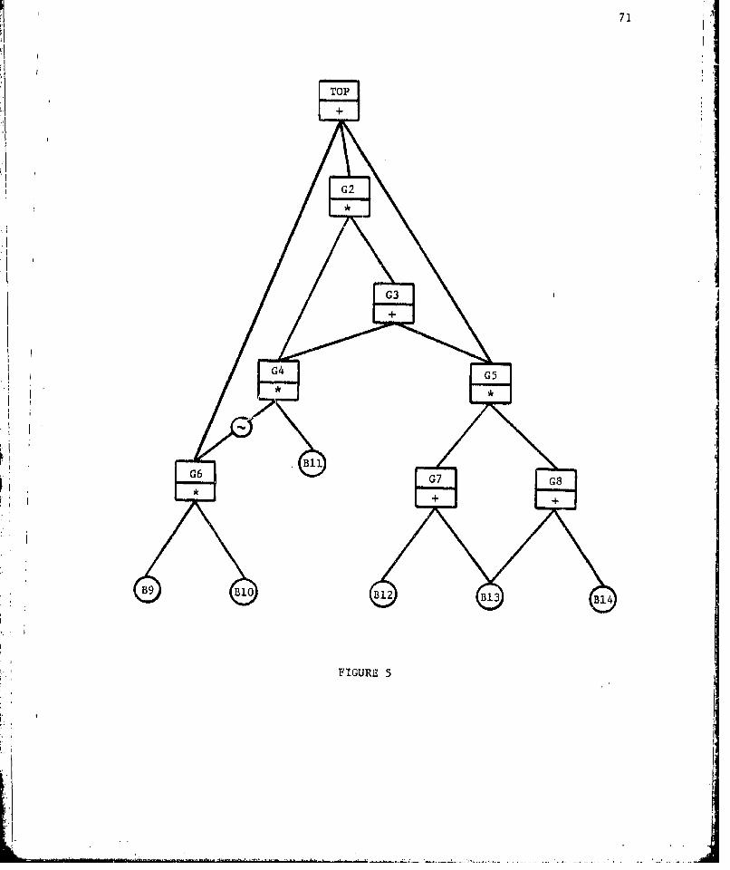
71]
TOP
+
G42
IG6G7G
FIGURE 5

72 j11.3 Execution Instructions
In some applications, the analyst may not wish to include any
option instructions for a run; a *TREE or *XEQ instruction should then
immediately succeed the ENDTREE card or the execution instruction
for the previous run. An execution instruction consists simply of the
name "*XEQ" or "*TREE" left-Justified in field 1. In the absence of
options, FTAP responds to a *XEQ instruction by seeking a minimal
implicant family in terms of basic events for the fault tree top node.
FTAP responds to a *TREE instruction by performing a structural analysis
of the input tree and printing three types of information: (1) a
representation of the tree, which is similar to a listing of gate node
specification instructions; (2) an "inverse" tree, which identifies,
for each gate or basic node u , the set of immediate supernodes of u
and (3) a representation of each modular subtree whose top node is a
simple module for the fault tree top node. Binary indicated implicant
counts are also printed for each modular subtree and its dual.
As an illustration, assume that 'the ENDTREE card of the example
tree specification is followed by the two instructions:
*TREE
*XEQ
Output for the first run begins with the tree representation:
I'
.. . . . . . . -.i-----..
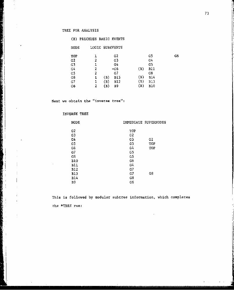
73
TREE FOR ANALYSIS
(B) PRECEDES BASIC EVENTS
NODE LOGIC SUBEVENTS
TOP 1 G2 G5 G6G2 2 G3 G4G3 1 G4 G5G4 2 -G6 (B) B1.1G5 2 G7 08G8 1 (B) B13 (B) B1407 1 (B) B12 (B) B1306 2 (B) B9 (B) 310
Next we obtain the "inverse tree":
INVERSE TREE
NODE IMMEDIATE SUPERNODES
G2 TOPG3 G2G4 G3 G2G5 G3 TOPG6 G4 TopG7 G5G8 05BlO G6Bll G4B12 G7B13 G7 G8B14 G8B9 G6
This is followed by modular subtree information, which completes
the *TREE run:
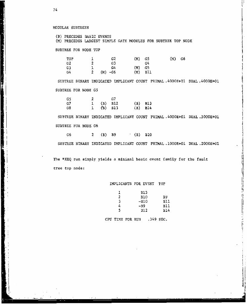
74
MODULAR SUBTREES
(B) PRECEDES BASIC EVENTS
(M) PRECEDES LARGEST SIMPLE GATE MODULES FOR SUBTREE TOP NODE
SUBTREE FOR NODE TOP
TOP I G2 (M) G5 (M) G602 2 G3 G4G3 1 G4 (M) G5G4 2 (M) -G6 (M) BlI
SUBTREE BINARY INDICATED IMPLICANT COUNT PRIMAL .4000E+O1 DUAL .4000E+O1
SUBTREE FOR NODE G5
G5 2 G7G7 1 (B) B12 (B) B13G8 1 (B) B13 (B) B14
SUBTREE BINARY INDICATED IMPLICANT COUNT PRIMAL .4000E+Ol DUAL .2000E+O1
SUBTREE FOR NODE G6
G6 2 (B) B9 (B) B10
SUBTREE BINARY INDICATED IMPLICANT COUNT PRIMAL .1000E+O1 DUAL .2000E+01
The *XEQ run simply yields a minimal basic event family for the fault
tree top node:
IMPLICANTS FOR EVENT TOP
1 B132 BIO B93 -B1O nil4 -39 Bil5 312 B14
CPU TIME FOR RUN .349 SEC.

75
The flexibility of FTAP is due to a large variety of options
discussed in the next section; even for simple fault trees, the analyst
will probably wish to include some of these instructions before *TREE
or *XEQ. All options affect a run initiated by a *XEQ instruction.
However, when the *TREE instruction is used, the only options that
are effective are those that modify the fault tree (TRUE, FALSE) or
select gate events for analysis (PROCESS, ALL).
11.4 Option Instructions
The first card of each option instruction contains the option
name in field 1. This initial card will be the only card for all
instructions except TRUE, FALSE, PROCESS, NELSON, and IMPORT. Options
TRUE, FALSE, PROCESS, and NELSON may be continued on subsequent cards
in the same manner as gate node definition instructions, by lenving
fields 1 and 2 blank on continuation cards; the number of continuation
cards is not restricted. The IMPORT option usually consists of more
than three cards but does not utilize the common continuation scheme.
Options other than these also have fields 2 through 8 blank, except
for MAXSIZE, which utilizes field 2.
Any option may be used for a run, but there are certain pairs
of incompatible options, and use of both options is treated by FTAP
as an error. In addition, a particular option may appear no more than
once for a run. But no restriction is placed on the number of
options that may be specified for a run or their input order.
We discuss options according to five functional categories.
f

76
11.4.1 Fault Truc Modification (TRUE. FALSE)
TRUE and FALSE permit any gate or basic event variables to be
taken as identically true or false for a run. Node names are entered
in fields 3 through 8 of these instructions, with preceding dashes
signifying complementation; field 2 is blank.
The effect of setting event variables to true or false is
accomplished by constructing a modified version of the input
fault tree. An implicant family generated by FTAP in response to
the *XEQ instruction then applies to this modified tree, as does
tree structure data provided for the *TREE instruction. Nodes
listed on TRUE and FALSE instructions do not appear in the modified
tree, nor do any of their supernodes whose associated event variables
become true or false. Some logic Indicators for gate nodes in
the new tree may, of course, differ from those in the input tree.
As an example, the Figure 5 tree is transformed to the tree of
Figure 6 through the instruction:
Col. 1 21 31
TRUE -G3 B12
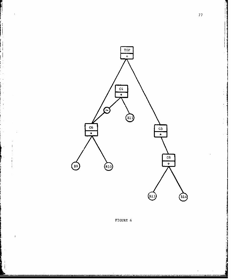
771
H ~TOP IG4I
G6 G5
I G8I +
B13 B14
FIGURE 61
__ __ __-_ --_ -_ ----_____I-- --

78
11.4.2 Gate Event Selection (PROCESS, ALL)
The analyst may wish to obtain implicant families for events
associated with gate nodes other than the input tree top node; this
is achieved by using a PROCESS or ALL instruction. The PROCESS
instruction has gate node names in fields 3 through 8, with dashes
opzionally preceding these names. Field 2 is always blank. The ALL
option consists simply of the string "ALL" in field 1. When the
*XEQ instruction initiates the run, an implicant family is obtained
for x if the name for node u appears without a preceding dashu
on a PROCESS instruction; a preceding dash results in an implicant
family for x ( X_ ) . The PROCESS instruction, in fact, determines
modular structure {M by specifying the set of events Qj jEM(Q)
The ALL instruction is less selective, and, when used in conjunction
with an *XEQ instruction, provides implicant families for xu for
every gate node u , as well as a family for x if the fault tree--U
contains complementing arcs. With the ALL option, the set Q for
the modular structure is thus either the set G of all gate nodes
or G U (-G)
The ALL option is perhaps more useful when a *TREE instruction
initiates the run. In this case, output from the tree structure
analysis procedure includes information on the modular subtree for
every gate node. On the other hand, the procedure provides modular
subtree information only for nodes corresponding to events in M(Q)
if the set Q is selected through a PROCESS instruction.
- n -

79
Wben PROCESS and ALL options are absent, FTAP takes Q to
consist only of the fault tree top node, unless the input fault
tree has more than a single top node. In the latter case, absence
of both instructions is treated as an error. Events in Q which
are identically true or false are messaged at the beginning of run
and excluded from further consideration.
PROCESS and ALL are incompatille, and it is an error to specify
both for the same run.
11.4.3 Methodology Specification (PRIME, ALLNEL, NELSON, MSUP, MSDOWN,WRKFILES, MSONLY, DUAL, UPWARD, MINCHECK)
Options discussed here affect the manner in which FTAP obtains
implicant families, so these instructions are only meaningful for runs
initiated by the *XEQ instruction. Except for NELSON, these options
consist only of the instruction name in field 1 of a card.
PRIME, ALLNEL, and NELSON instructions signal that the Nelson
method is to be employed in obtaining certain minimal families M
in the modular structure. PRIME Indicates that this method is to be
used only when the modular subtree for event j contains a complementing
arc. PRIME thus guarantees that all families ger.erated for a run consist
of prime implicants; of course, this option has no effect if the input
fault tree is devoid of complementing arcs.The ALLNEL option, on the other hand, is effective for any input
tree. In this case, the Nelson method is utilized in obtaining all
M in the modular structure.
ij
LI -
Ii80
*-1
The NELSON option permits the Nelson method to be applied
selectively for events corresponding to node names in fields 3
through 8 of this instruction. That is, if the name for some node
u icurs in one of these fields without a preceding dash, then as
lon• as u E M(Q) M is determiTid by the Nelson method; a preceding
dash has the same effect for M . An event j Il M(Q) selected
by this instruction is ignored, so the analyst should have some
knowledge of M(Q) , perhaps derived from an earlier structural
analysis of the fault tree.
If a modular subtree contains complementing arcs, it is possible
for an event variable associated with the subtree top node to be
identically true or false. The family M for a variable xj which
is identically false is always empty, and FTAP gives this result.
However, if the variable x is identically true, this may not be
apparent from FTAP results unless the Nelson method is utilized in
finding M. . The first task in this method is to find a complete
minimal family Md for the dual modular subtree, and M is empty
if x is true. Should M be empty, FTAP prints an appropriate
message aad terminates the run.
PRIME, ALLNEL, and NELSON are incompatible with each other, and
only one of the three may appear for a run.
Because FTAP automatically makes a reasonable choice between
MSDOWN and MSUP algorithms in finding families M, , the analyst
will not often want to include a MSDOWN or MSUP option for a run.
When the Nelson method is employed for a family , FTAP automatically
chooses the algorithm MSDOWN to first find a complete minimal family
for the, dual modular subtree, but the user may override this choice
-. 1• | I I I II I ' .1 I--

through the MSUP option. When the Nelson method is not employed,
FTAI chooses the MSDOWN algorithm to find M unless implicant
elimination based on size or importance is enabled, in which case
the MSUP method is chosen. Again, either choice may be overriden
through a MSUP or MSDOWN option. Since fields 2 through 8 of
these options are blank, selective application to the families Aj
is not possible. The presenc i of both options for the same run
is treated as an error.
WRKFILES informs the program that sequentially organized file
space on magnetic disk is available for use as working storage.
FORTRAN file numbers 10, 11, and 12 must be assigned if this option
is used. This storage is only available to subroutines that imple-
ment the dual algorithm. Though MSDOWN and ORDOWN methods both
employ the dual algorithm, magnetic disk storage, when necessary,
will most often be utilized in application of the Nelson method to
large modular subtrees. Thus, the WRKFILES option will usually appear
in conjunction with ALLNEL, PRIME, or NELSON. If the WRKFILES option
has not been used for a run which must be terminated because of
insufficient working space in main memory, a message may be printed
suggesting that main memory could have been supplemented by magnetic
disk storage. In this case, it is reasonable for the analyst to try
a rerun with a WRKFILES instruction.
Once the modular structure has been found, the procedure for
finding implicant families in terms of basic events is very efficient
computationally, but for large fault trees, this final step might
require a great deal of main memory workspace. The MSONLY option

82j
instructs FTAP to bypass this step, so only the modular structure
is determined. This instruction will also lead to more efficient
use of main memory in obtaining the modular structure, since families
M need not be retained once they have been printed. Also, FTAP
includes a subroutine which, when provided with the family M in
terms of largest simple modules for j , counts the number of implicants
in the minimal basic event family (without deriving this family).
Separate counts are accumulated by implicant size and printed by the
subroutine. If MSONLY is specified, the routine is called for each
j s M(Q)
The DUAL option simply indicates that all implicant families
for a run are to be derived for the dual of the input fault tree.
Thus, if an implicant family associated with the primal tree consists
of system cut sets, a corresponding minimal path set family is obtained
by using the DUAL instruction.
The UPWARD option invokes an algorithm not explicitly stated
in Part I. This method closely resembles the MSUP algorithm: The
general MSUP technique is applied to the entire fault tree rather
than a modular subtree, with basic events replacing largest simple
modules. Thus implicant families are generated directly in terms of
basic events without utilizing the modular structure. The UPWARD
option may be useful when the required minimal implicant families
in terms of basic events are expected to be small, which might be
the case even for large fault trees if size and importance elimination
options are included for a run. Because the modular structure is not
determined when this option is specified, certain other options are

83
incompatible with UPWARD. These are NELSON, PRIME, MSDOWN, MSUP,
MSONLY, MODSIZE, MSPRINT, and MSPUNCH, the last three of which
we will consider shortly.
The MINCHECK instruction is only effective when it accompanies
the UPWARD option. MINCHECK specifies that minimization only be
applied to implicant families for events in the set Q determined
by PROCESS or ALL options, or in the absence of these options, to
the family for the fault tree top node. Thus, intermediate families
generated for events that are not of interest to the analyst are not
minimized.
11.4.4 Control of Printed and Punched Output (MSPRINT. STATUS,DSTATUS, PUNCH, MSPUNCH, NOPRINT)
These options control output information regarding implicant
families and are effective only for runs initiated with a *XEQ
instruction.
MSPRINT instructs FTAP to include the modular structure families
in printed output. This option is unnecessary when MSONLY is
provided, because MSONLY also enables printing of the modular structure.
As an illustration, suppose the ENDTREE card for specification of the
Figure 5 tree is followed by the instructions:
MSPRINT
*XEQ
Modular structure output is then:

84
IMPLICANTS IN TERMS OF LARGEST SIMPLE MODULES
IMPLICANTS FOR EVENT G6
I. B10 B9
IMPLICANTS FOR EVENT -G6
1 -B92 -B10
IMPLICANTS FOR EVENT G5
1 B12 B14
2 B13
IMPLICANTS FOR EVENT TOP
1 G5 rl2 G63 -G6 BI1
The STATUS option yields information on the progress of generat-
ing each minimal implicant family, giving the number and maximum
size of implicants in various intermediate families, as well as data
on computation times and the amount of unused main memory. STATUS :
provides a brief record of each iteration of the MSDOWN method. As
an illusftration, consider the instruction group:
MSPRINT
STATUS
*XEQ
A sample of the output for the event TOP modular structure family
from a run initiated by these instructions is as follows:
I ! II II I! l
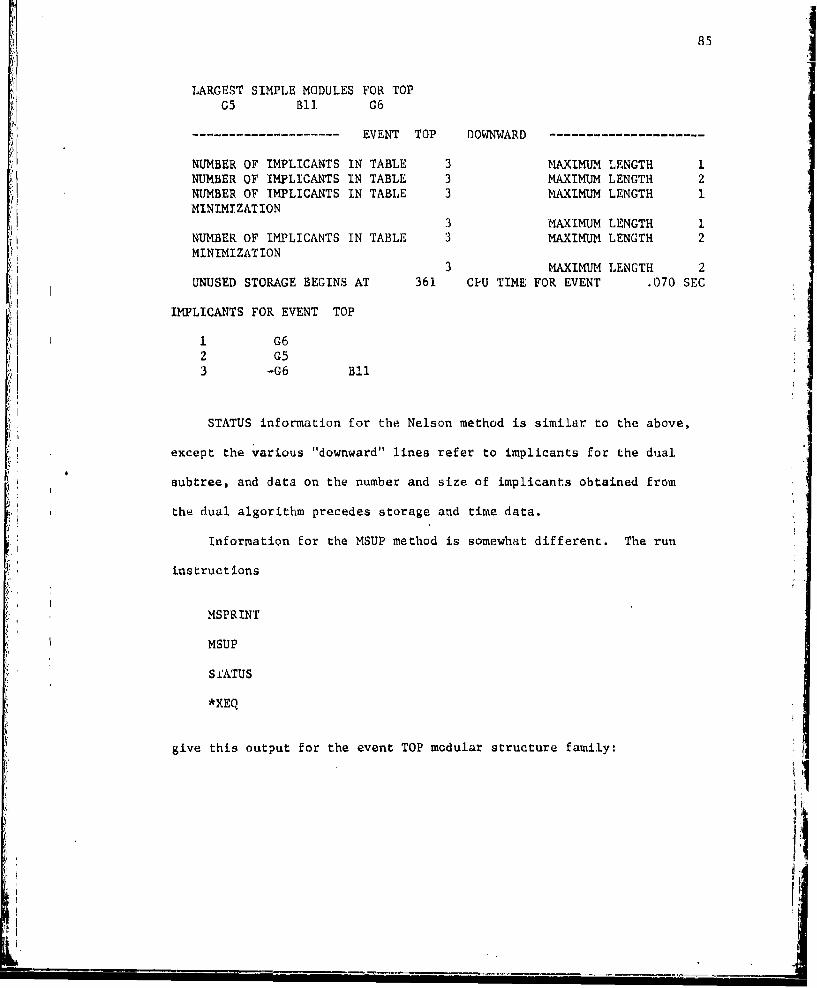
85
LARGEST SIMPLE MODULES FOR TOPG5 BII G6
EVENT TOP DOWNWARD
NUMBER OF IMPLICANTS IN TABLE 3 MAXIMUM LENGTH 1NUMBER OF IMPLICANTS IN TABLE 3 MAXIMUM LENGTH 2NUMBER OF IMPLICANTS IN TABLE 3 MAXIMUM LENGTH IMINIMIZATION
3 MAXIMUM LENGTH 1NUMBER OF IMPLICANTS IN TABLE 3 MAXIMUM LENGTH 2MINIMIZATION
3 MAXIMUM LENGTH 2UNUSED STORAGE BEGINS AT 361 CPU TIME FOR EVENT .070 SEC
IMPLICANTS FOR EVENT TOP
1 G62 G53 -G6 Bll
STATUS information for the Nelson method is similar to the above,
except the various "downward" lines refer to implicants for the dual
subtree, and data on the number and size of implicants obtained from
the dual algorithm precedes storage and time data.
Information for the MSUP method is somewhat different. The run
instructions
MSPRINT
MSUP
S &ATUS
*XEQ
give this output for the event TOP modular structure family:
jil

86
LARGEST SIMPLE MODULES FOR TOPG5 811 G6
EVENT TOP DOWNWARD
NUMBER OF IMPLICANTS IN TABLE 3 MAXIMUM LENGTH 1MINIMIZATION 3 MAXIMUM LENGTH 1
EVENT G2 DOWNWARD ---
NUMBER OF IMPLICANTS IN TABLE 1 MAXIMUM LENGTH 1
EVENT G4 DOWNWARD
NUMBER OF IMPLICANTS IN TABLE I MAXIMUM LENGTH 2
EVENT G4 UPWARD hNUMBER OF IMPLICANTS IN TABLE 1 MAXIMUM LENGTH 2
EVENT G2 UPWARD -
NUMBER OF IMPLICANTS IN TABLE i MAXIMUM LENGTH 2
EVENT TOP UPWARD - - -
NUMBER OF IMPLICANTS IN TABLE 3 MAXIMUM LENGTH 2MINIMIZATION 3 MAXIMUM LENGTH 2
UNUSED STORAGE BEGINS AT 387 CPU TIME FOR EVENT .129 SEC
IMPLICANTS FOR EVENT TOP
1 C62 G53 -G6 BIlI
The "downward" information now represents successive applications of
the ORDOWN algorithm to events TOP, G2, and G4. These events are then
considered in upward order, as the family for TOP in terms of largest
simple modules is generated. The "upward" information format is also
used in a rather obvious way to chart the progress of constructing
basic event families, whether this construction proceeds from the
modular structure or in the manner associated with the UP1JARD option.

87
DSTATUS causes the subroutine package for the dual algorithm
to provide data on the sizes of various tables associated with that
algorithm. This data is only printed when the Nelson method is used
and the subroutine package is applied to the implicant family for a
dual modular subtree. Some familiarity with Reference [17] is required
to interpret this output.
PUNCH and MSPUNCH options allow implicant families to be punched
on 80-column cards for input to other programs. FORTRAN file number 7
should be assigned to the card punch (or magnetic disk) if these
instructions are used. Events associated with the input fault tree
are represented by positive and negative integers punched output,
and whenever the MSPUNCH option is used, this numbering scheme is the
same as suggested in Part I. MSPUNCH enables punching of the modular
structure, and determines that, for the q nodes of the input fault
tree, integers 1 to p are to represent gate nodes on punched output
and p + I to q are to represent basic nodes. The PUNCH option
causes basic event families to be punched. Unless MSPUNCH accompanies
the PUNCH instruction for a run, integers 1 to q - p number basic
nodes on output.
When either MSPUNCH or PUNCH is used, the firsr group of puvched
cards for a run gives the correspondence between node names and numbers.
The initial card of the group has the FORTRAN format (5HNAMES,15),
where the single integer field contains the number of names (which will
be q if MSPUNCH is specified and q - p if only PUNCH is specified).
On the remaining cards node numbers are paired with node names, with
up to five pairs appearing on a card in the format (5(15,3H - ,AS)).

88
The modular structure, if reque.sted, is given by the next group
of cards, whose initLia card has a (5HIMPMS,15) format, containing
the run number in the integer field. The representation of each
family M then begins with a (5HEVENT,15,16) format header card,
having the positive or negative integer j in the first field arid
the number of implicants in the family in the second. Following
the header card, each impllcant of the family starts on a separate
card witha (1615) format and may continue on additional cards with
the same format. On the first card for an implicant, field 1 always
contains the number of events in the implicant. These events are
represented in fields 2 through 16 of the first card and 1 through 16
on subsequent cards.
Output for basic event families is preceded by a (5HIMPBE,I5)
format card, with the run number in the integer field. The general,I
format for representing these families follows that of the modular
structure, where the basic event families U j take the place ofi jEQ
j . Again, Q either contains the fault tree top node or
events indicated by a PROCESS or ALL instruction.
Finally, the analyst may sometimes wish to obtait, punched output
but suppress printed output for large basic event families. In such
cases, the NOPRINT option should accompany the PUNCH option. NOPRINT
only suppresses printing of basic event families and does not affect
the MSPRINT option.
I:?. ~

89
11.4.5 Implicant Elimination Based on Size and Importance (MAXSIZE,MODSIZE, IMPORT)
These options are compatible with all of the algorithms MSDOWN,
MSUP, and Nelson, as well as the method associated with the UPWARD
instruction. If size or importance options are included for a run
and options MSDOWN, PRIME, ALLNEL, and NELSON are absent, the MSUP
algorithm is chosen automatically by FTAP, even foli modular subtrees
containing complementing arcs. However, it has been pointed out in
Part I that when the MSUP method is applied to a subtree with cum-
plementing arcs, the resulting subfamily of size or importance
restricted sets may not be meaningful. Thus, in utilizing these
options, the analyst will usually want to insure that the Nelson
method is employed for such subtrees.
The MAXSIZE option imposes a uniform size restriction on implicants
in the modular structure and basic event families generated by FTAP.
Field 2 of this instruction gives the maximum number of events permitted
in an implicant; a positive integer may appear anywhere in the field.
Fields 3 through 8 of the card are blank.
As discussed in Part I, modular size importance is often a more
efficient criterion for implicant elimination than a simple size
restriction. This criterion is applied in the manner suggested in
Subsection 1.3.2, which we briefly recall: The subfamilies {M'}I -~M(Q)
are generated in "upward" order, with M constructed followingIC
families for subevents of j . An implicant M is retained in M'
only if c o(m) does not exceed the fixed size restriction, wheremeM
a(m) - . if m is a basic event, and for m a gate event, o(m) is
iI

90
available from an earlier computation which foillowed construction
of M' , i
min~ a(k) (Mil , 0)KEW' krKm
FTAP implements elimination based on modular size importance when
the MODSIZE option accompanies MAXSIZE; in this case, MAXSIZE specifies
the fixed size restriction. MODSIZE is not effective in the absence
of the MAXSIZE option.
FTAP also allows for implicant elimination based on the product
importance criterion. Here an implicant M is retained in M' only
if NT i(m) exceeds some critical value c , where t(m) is anmrM
arbitrary value between 0 and I for in a basic event, and for
m a gate event, 1(m) has been determined from
ma ( r i(k) (NM 0)KtM'\k•K / m
The criterion is applied again when basic event families are obtained
from the modular structure.
The product importance option requires a group of cards to
specify the values i(.) for basic events and the critical value c
The first card of the group contains only the option name "IMPORT"
in field 1; other fields are blank. Cards which assign i(.) values
follow this initial card. These cards always have field 1 blank,
a positive decimal value between 0 and I in field 2, and basic I
event names in fields 3 through 8, with optional dashes preceding these
latter fields. The value in field 2 may be in FORTRAN E or F ,!
r'

91
format and must contain a decimal point. An F-format item, such
as .5 or .001, may appear anywhere within the field, but E-format
items, such as 1.25E-2 or .lE-l, must be right-justified. Should the
name for basic node u appear on a card, t(u) is assigned the
value in field 2 of that card when the name is not preceded by a dash;
a preceding dash causes the field 2 value to be assigned to t(-u)
As many cards as desired may be used to set tL() values, but it is
not required that values be provided for all basic events: FTAP assigns
t(k) a default of 1 for any event k not represented on one of
these cards.
The card that must terminate the product importance group has the
string "LIMIT" left-justified in field 1 and a decimal value between
0 and 1 again in field 2. Fields 3 through 8 are blank. The field
2 value is the critical value c for the importance test.
As a simple illustration of the above options, suppose for the
example tree, the analyst desires only prime implicants consisting of
a single basic event, and implicants involving node B9 are not of
interest. Suitable cards for this run are:
Col. 1 1i 21 31
MAXSIZE iIMPORT
.4 B9 -B9LIMIT .5PRIME*XEQ

a
92
11.5 Program Implementation
FTAP is available in two distinct versions that differ only in
the internal storage format for representing implicant sets. FTAPl
stores an implicant as a variable number of consecutive computer
words in main memory. The first word of the group contains the
integer number of events in the set, and a positive or negative
integer value in each of the remaining words identifies an implicant
event. FTAP2, on the other hand, stores an implicant set as a fixed
group of consecutive words, and a fault tree event is associated with
a unique bit position in one of these words. Bit positions corre-
sponding to events in the implicant contain the value 1, whereas
other bit positions contain 0. The fixed number of words required
for an implicant set depends on the computer word length, the particular
stage of FTAP processing, and whether the input fault tree contains
complementing arcs. When modular structure families are constructed
for a fault tree without complementing arcs, the number of words must
be sufficient to accommodate one bit position for each gate and basic
node. Fur fault trees with complementing arcs, two bits are needed
for a node, one for each event associated with the node. When basic
event families are constructed, the situation differs only on the
fact that bit positions are not needed for representation of gate
events.
FTAP2 is the more efficient of these two versions in terms of
computation time and should be chosen for most applications. However,
for large fault trees (having, say, more than 200 gate nodes), it is
often feasible only to obtain implicants having a small number of events.
The storage format of FTAP1 becomes an advantage in such applications.

93
FTAP1 and FTAP2 are designed for use on most general purpose
computers. The codes have been carefully prepared to ensure that
program logic is tight and efficient, and subroutines for minor
tasks such as sorting and searching use good standard algorithms,
as given in (9]. The FORIRAN portion of each program conforms to
ANSI specifications, except for array subscripts, which are apt to
consist of expressions using two or more simple FORTRAN integer
variables with addition, subtraction, and multiplication operations,
and sometimes the integer absolute value operation. Most FORTRAN
compilers allow such expressions.
Main memory work space for either code is confined to one single
subscripted integer array, denoted by the FORTRAN name IA. Storage
in this array is dynamically allocated for maximum efficiency in use
of main memory. Because fault trees of appoximately the same size
may differ considerably in their structure, it is difficult to state
even roughly how large IA should be to accommodate analysis of a
fault tree with some given number of nodes. The analyst should make
TA as large as feasible for the environment in which the program is
implemented; for instance, if the program is required to execute in
a fixed partition of computer main memory, then the object code length
plus storage for IA should fill the partition. If the environment is
such that program use becomes more inconvenient as storage requirements
increase, an Liitial length of IA should be chosen perhaps between 300
and 1000 times the maximum number of gate nodes in any tree to be
analyzed; this length may then be increased as necessary.
Implementation of FTAPl or FTAP2 is accomplished according to
the following steps:

94 I1. The desired dimension of the array IA should be set in
the declarative statement for this array near the beginning
of the main program. Since the code must be capable of
determining when storage requirements exceed availability,
the length of the array must be provided for internal program
use. This is done by initializing the variable IASIZE
through a FORTRAN DATA statement, which also appears near
the beginning of the main program.
2. The first executable statement in the main program for FTAP2
assigns a positive integer value to the variable LWORD. This
value should be set to the length of a computer word less one.
3. When accessed by other routines, the REAL function TIME returns
the amount of elapsed time since the beginning of the computer
job. The proper form of the subroutine CALL statement in
function TIME may depend on the particular computer installation,
and this statement should be modified accordingly.
4. The group of assembler language routines should be chosen to
correspond to both the computer and FORTRAN compiler used.
Three groups of assembler language routines are supplied
v ith FTAPI or FTAP2: for use with (1) CDC 6600/7600 machines
atid RUN compiler linkage convention, (2) CDC 6600/7600
machines and FTN compiler linkage convention, or (3) IBM 360/370
machines (G or H compiler linkage convention). To implement
FTAP1 or FTAP2 on other machines, one or more assembler routines
must be prepared according co specifications given in the
i�following section.

95
11.6 Specifications for Assembler Routines
The routines discussed in this section are all very simple,
and the largest should not require many more than 25 statements in
any assembler language. FTAP1 utilizes only routine CCM, but all
routines are accessed by FTAP2.
1. CCM(IWI, IW2, ITEST):
CCM logically compares the contents of computer words IWI and
IW2 and returns the result of the comparison in word ITEST. If
contents of IWI and IW2 are identical, then ITEST will contain a 0
otherwise the value in ITEST depends on the highest bit in which the
words differ. When this bit is 1 in IWl and 0 in IW2, ITEST
is returned as 1 ; in the reverse situation ITEST is returned as -1
2. ORM(IW1, IW2, 1OR):
The contents of word IOR returned by this routine is simply a
logical OR of words IWl and IW2.
3. ANDM(IWI, lW2, IAND):
ANDM returns in word IAND the result of a logical AND of IWM
and IW2.
4. PUTM (LV, IV, IW):
When PUTM is accessed, IV is an array of successive words containing
positive integer values in increasing order. No value exceeds the
number of bits in a computer word. The location LV contains a positive
integer representing the length of IV. The function of PTUM is to

96
place a 1 in each bit position of word IW numbered by an integer
in array IV; other bit positions are set to 0 . As an example,
suppose the computer word length is 16, and PV'TM is accessed with 4 Iin LV, and IV(1) through IV(4) contain, respectively, 2, 5, 7, and 16.
On return, IW then contains the bit pattern "100000000lOlO010."I
The bit numbering for this example is increasing from right-to-left.
5. GETM (IW, LV, IV)!
GETM performs the reverse operation of PUTM. On return, IV is
a vector of consecutive words containing bit numbers for all bits
that are 1 in word IW. These integers are in increasing order in
IV, and the number of integers in this vector is returned in LV.
GETM may be accessed with IW having 0's in all bit positions, in
which case LV is returned with an integer value of 0
6. BCM (IW, NBITON):
BCM returns in NBITON the count of bit positions containing 1
in word IW. The value in NBITON is thus an integer between 0 and
the number of bits in a computer word.

97
REFERENCES
[1] Aho, A., J. Hopcroft and J. Ullman, THE DESIGN AND ANALYSIS OF
COMPUTER ALGORITHMS, Addison-Wesley, Reading, Mass., 1974.
[2] Barlow, R. E. and F. Proschan, STATISTICAL THEORY OF RELIABILITY
AND LIFE TESTING, Holt, Rinehart and Winston, New York,
1975.
[3] Chatterjee, P., "Fault Tree Analysis: Relicul.lity Theory and
Systems Safety Analysis," ORC 74-34, Operations Research
Center, University of California, Berkeley, (1974).
[4] Chatterjee, P., "Modularization of Fault Trees: A Method to
Reduce the Cost of Analysis," in RELIABILITY AND FAULT TREE
ANALYSIS, R. E. Barlow, J. B. Fussell and N. D. Singpurwalla,
(editors), SIAM, 1975.
[5] Edmonds, J. and D. R. Fulkerson, "Bottleneck Extrema," Journal of
Combinatorial Theory, Vol. 8, pp. 299-306, (1970).
[6] Fussell, J. B. and W. E. Vesely, "A New Methodology for Obtaining
Cut Sets," American Nuclear Society Transactions, Vol. 15,
No. 1, pp. 262-263, (June 1972).
[7] Fussell, J. B. et al., MOCUS: A COMPUTER PROGRAM TO OBTAIN
MINIMAL SETS, Aerojet Nuclear Co., Idaho Falls, 1974.
[8] Hulme, B. L. and R. B. Worrell, "A Prime Implicant Algorithm
with Factoring," (prepublication copy).
[9] Knuth, D. E., THE ART OF COMPUTER PROGRAMMING, VOL. 3,
SORTING AND SEARCHING, Addison-Wesley, Reading, Mass., 1970.
[10] Lambert, H. E., "Fault Trees for Decision Making in Systems
Analysis," Report UCRL-51829, Lawrence Livermore Laboratories,
Livermore, California, (1975).l i I
98
[11] Nelson, R. J., "Simplest Normal Truth Functions," Journal of
Symbolic Logic, Vol. 20, pp. 105-108, (1955).
(12] Pande, P. K., M. E. Spector and P. Chatterjee, "Computerized
Fault Tree Analysis: TREEL and MICSUP," ORC 75-3,
Operations Research Center, University of California,
Berkeley, California, (1975).
(13] Pelto, P. and W. Purcell, "MFAULT: A Computer Prcgram for
Analysizing Fault Trees," Report BNWL-2145, Battelle
Pacific Northwest Laboratories, Richland, Washington,
(1977).
[14] Reusch, B., "On the Generation of Prime Implicants,"
Report TR 76-266, Department of Computer Science, Cornell
University, Ithaca, New York, (1976).
[15] Rosenthal, A., "A Computer Scientist Looks at Reliability
Analysis," in RELIABILITY AND FAULT TREE ANALYSIS,
R. E. Barlow, J. B. Fussell and N. D. Singpurwalla, (editors),
. SIAM, 1975.
[16] Whitesitt, J., BOOLEAN ALGEBRA AND ITS APPLICATIONS, Addison-
Wesely, Reading, Mass., 1961.
[171 Willie, R., "A Computer Oriented Method to Find Boolean Duals,"
(forthcoming).
[181 Worrell, R. B., "Using the Set Equation Transformation System
in Fault Tree Analysis," in RELIABILITY AND FAULT TREE
ANALYSIS, R. E. Barlow, J. B. Fussell and N. D. Singpurwalla,
(editors), SIAM, 1975.
m .. . " . . . . . . . .. . .
Related Documents