COMPUTER AIDED DESIGNING AND MANUFACTURING CAD/CAM PRACTICAL FILE ASHISH CAD/CAM practical course to fulfill the Design knowledge of the Mechanical Engineers as per the part of the syllabus using SOLIDWORKS and MASTERCAM for CAD/CAM practical training. Er. ASHISH KUMAR YADAV [email protected], contact- 9780027927,9501115414

Welcome message from author
This document is posted to help you gain knowledge. Please leave a comment to let me know what you think about it! Share it to your friends and learn new things together.
Transcript

COMPUTER AIDED DESIGNING AND MANUFACTURING
CAD/CAM PRACTICAL FILE
ASHISH CAD/CAM practical course to fulfill the Design knowledge of the Mechanical Engineers as per the part of the syllabus using SOLIDWORKS and MASTERCAM for CAD/CAM practical training.
Er. ASHISH KUMAR YADAV
contact- 9780027927,9501115414

BABA FARID GROUP OF ENGINEERING AND TECHNOLOGY
INTRODUCTION TO MODELING (USING CAD SOFTWARE)
INTRODUCTION TO THE CAD (COMPUTER AIDED DESIGN) :-
A CAD system is a combination of hardware and software that enables engineers to design everything from
furniture to airplanes. In addition to the software, CAD systems require a high-quality graphics monitor.
CAD is the use of computer system to assist in the creation modification, analysis, or optimization of a
design. CAD software is used to increase the productivity of the designer, improve the quality of design,
and improve communication through documentation.
CAD software for Mechanical Design uses CAD system allows to create 3D models like feature modeling,
surface modeling, and sheet metal modeling. It’s also provide the Assembly of the all parts with proper
mechanical mating relations. Also use of casting CORE and CAVITY, structural design in weldment toolbar,
pipe and tubing design and Various design analysis e.g. static analysis, dynamic analysis, fluid flow analysis,
thermal analysis is also available in the Solidworks.

BABA FARID GROUP OF ENGINEERING AND TECHNOLOGY
SOLIDWORKS
Solidworks is a 3d modeling software produced by Dessault system corp. ltd. Solid works is a CAD Tool and
its Parametric Feature based system it’s allows you to create 3d parts, assemblies and 2d drawings.
Parametric modeling everything is control by either Parameter, relations and dimensions. The basic
requirement for creating a solid model in every 3d CAD tool is a sketch. The sketch for the features is
drawn in the sketch ribbon inside the solid works. Let’s discuss each and every drawing and 3d tools with
some practical examples.
Before stating solidworks let’s familiar with the user interface of the software. When software starts
choose “new” for the creating new drawing part file.
You have 3 option available to you on your
solidworks screen 1. Part, 2. Assembly and 3.
Drawing
Choose part (either double click on in
or just click once and press “OK”.
Choose sketch ribbon in the solid
works screen and select first plane,
front, top and right and click on the
sketch icon.
Sketch environment is highlighted
and we can draw the
various 2d drawing using
2d drawing sketching in
solid works.
For setting the initial
units setting in
solidworks go to
“tools>options>click
documents and
properties > click on
“UNITS” and choose
your default units what
you need to choose e.g.
mmgs (millimeters,
grams, second)
IPS (inch, pound, second).

BABA FARID GROUP OF ENGINEERING AND TECHNOLOGY
PRACTICAL -1
2D DRAWING USING SKETCHER IN SOLIDWORKS – 2 DRAWING.
Open sketch environment in solid works choose one of default plane (say front) and click on the
circle icon on the sketch toolbar ribbon.
Draw a circle inside the drawing area first then choose smart dimension icon on the sketch ribbon
or right click and drag the mouse courser to UP you’ve automatically choose smart dimension tool.
Select the circle and give the proper
dimension as per given drawing.
Draw the same circle of diameter of
60 in same center point. Then draw
the line as per given drawing and give
dimensions with smart dimension
tool.

BABA FARID GROUP OF ENGINEERING AND TECHNOLOGY
You draw the object
similar as you see in the
screen to remove the
extra unwanted
objects choose trim
command in the sketch
ribbon and click on the
power trim option
available on the right
side of the properties
toolbar and select the
line you need to
remove it will
automatically delete or
disappear from the screen which object you don’t
need in this drawing.
The final object is prepare as per your drawing.
(You can also put the relationships in the object just
click the first object and second object holding down
the “ctrl” key the relation matched to the object will
appear on the right side on the properties toolbar
automatically and you can choose the appropriate
relation as you want to put inside the object.)
Choose or click on the “feature” ribbon inside the
solid works and choose ‘Extruded Boss/Base’ and
your object will automatically get extruded in the
“Z” direction give them hight you need to give say
40mm. click on OK .
Feature Power trim
Feature toolbar ribbon

BABA FARID GROUP OF ENGINEERING AND TECHNOLOGY
First object is completed as
per your drawing part and
you also learn how to extrude
the object using extruded
boss command in the solid
works.
Click on OK or green check
indicating on the left corner
or in right corner in the
properties manager.
Save the object with proper
name and close the solid
works.
-----------------------------------------
PRACTICE DRAWINGS

BABA FARID GROUP OF ENGINEERING AND TECHNOLOGY
PRACTICAL -2
3D MODELLING USING 3D FEATURES (MODELLING OF BENCH VICE, SCREW JACK)
SLIDING JAW SCREW
BASE
Before drawing the 3d model we need to draw the each component of the screw jack one by one here is the
simple model of the screw jack which contains 3 basic objects.
1. Base
2. Screw
3. Sliding jaw
CREATING BASE FEATURE
1. Open the solid works and
draw the object as same as
shown in the object with
same dimensions and
extrude this object using
extrude boss to 64mm.
2. fter extrude select the back
face of the object and click
on sketch tool shown in the sketch tool
ribbon or highlight icon of the sketch tool.
Click “ctrl+8” and draw the object shown
below and after completion of the drawing
of the object again choose extrude boss to
extrude the sketch in desired direction in
22mm.
The object is shown in the next page.

BABA FARID GROUP OF ENGINEERING AND TECHNOLOGY
3. Again select the back
face of the base plate
and draw the diagram
shown in the figure 6.
And this time choose
“Extruded cut” and
choose “through all”
and cut all the material
through to the object.
And also draw a
concentric hole of the
diameter of 14.50 mm
and also extruded cut
this hole to through all.
4. Click on the green check
and save the file named “base”.
Fig- 6
2nd PART (sliding jaw)
BABA FARID GROUP OF ENGINEERING AND TECHNOLOGY
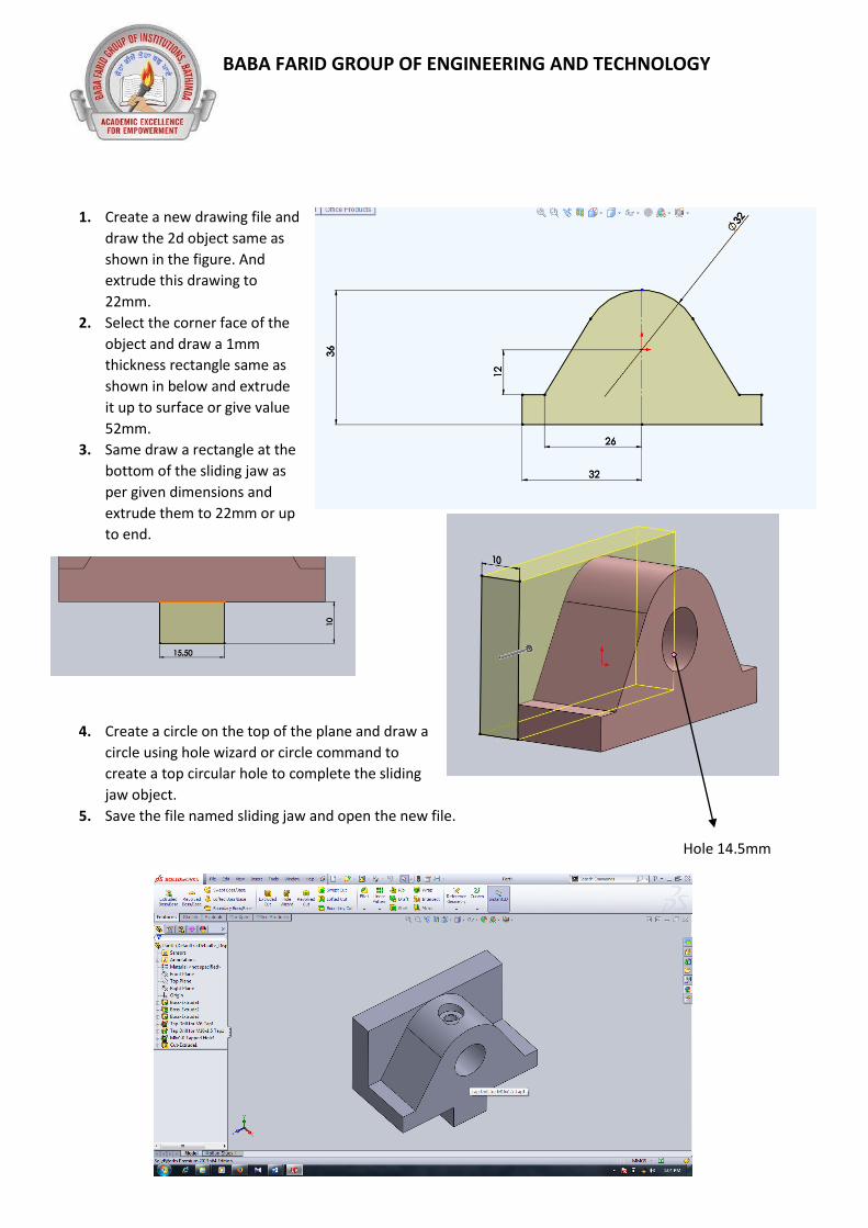
1. Create a new drawing file and
draw the 2d object same as
shown in the figure. And
extrude this drawing to
22mm.
2. Select the corner face of the
object and draw a 1mm
thickness rectangle same as
shown in below and extrude
it up to surface or give value
52mm.
3. Same draw a rectangle at the
bottom of the sliding jaw as
per given dimensions and
extrude them to 22mm or up
to end.
4. Create a circle on the top of the plane and draw a
circle using hole wizard or circle command to
create a top circular hole to complete the sliding
jaw object.
5. Save the file named sliding jaw and open the new file.
Hole 14.5mm

BABA FARID GROUP OF ENGINEERING AND TECHNOLOGY
SCREW
To create a screw First draw a diagram as shown in figure below as same as given
dimension.
After draw this diagram go to the feature ribbon toolbar and choose the Revolved
Boss/Base and choose the
reference line and the
remaining object to revolve
and give them the degree of
rotational angle say 360 for
full round and our object is
completed. Now we have
the three basic object and
We cleared some of the
main basic feature tools. Now we move on to the assembly drawings.

BABA FARID GROUP OF ENGINEERING AND TECHNOLOGY
PRACTICE DRAWING

BABA FARID GROUP OF ENGINEERING AND TECHNOLOGY
PRACTICAL 3
ASSEMBLY AND DRAFTING WITH PROPER MATING CODITION AND INTERFARANCE CHECKING
We are try to assemble the machine vice with proper mating codition on this practical
Open Solidworks software and choose new file and now click on “assembly” twice or just click once
and press OK.
You will open a assembly environment window.
Click on the Browse.. button to choose the assembly file one by one. First select the base.
Insert the first component named BASE you saved before in part design and click on the
screen object is automatically align and fix on that position because the first object we
choose in the assembly in
the solidworks is
considered as a fix object
so that the remaining part
assemble properly with
this base part.
Again select “insert
component” on the
toolbar ribbon and
choose the second object
and place the second
object on anywhere on
the assembly screen.
Click on the “Mate” icon
and select the both
corner face of the base and sliding jaw in the assembly the object is
automatically align with the second object with appropriate realation fits on
that mate automatically but if you won’t satify with that mate you can
change the mate relations.
There are so many types of mate available in the solidworks.
1. Coincident mate
2. Parallel mate
3. Perpendicular
4. Tangent
5. Concentric mate
6. Distance mate
now select the final screw component and choose the circular face of screw
and hole of the cast iron base.

BABA FARID GROUP OF ENGINEERING AND TECHNOLOGY
first select the two corner face of the
base and sliding jaw as shown in
figure and choose coincident as a
mating condition of the both.
Now choose the bottom grooved face
of base and sliding jaw as similar as
the first one and again choose
coincident.
Select the two mating face and
choose the “distance mate” and give a
distance. Say 50mm
Now choose the screw
component and click on
the “mate” on the toolbar
ribbon and choose the
circular face of the rod
and hole of the base.
Your assembly of the
simple vice is completed
now we move on to the
collision detection part in
the solid works.
for the collision detection
first choose the move tool
in property manager
choose the collision
detection and choose the
object you want to study
of the collision between
them.
The object is highlighted
and creates sound when
some interference or
collision occurs.

BABA FARID GROUP OF ENGINEERING AND TECHNOLOGY
ASSEMBLY PRACTICE DRAWING

BABA FARID GROUP OF ENGINEERING AND TECHNOLOGY
CAM (COMPUTER AIDED MANUFACTURING)
INTRODUCTION – CNC (Computer Numeric Control system, a dedicated computer is used to perform all
the basic NC functions as per the control program stored in the memory of the computer. Thus the
machine controlled date comes directly from the computer memory and not for the continuous tape as
in case of head-wired NC system. The use of computer makes the system flexible so that the system cand
operate on a different type of machine tool.
BASIC SIMPLE WAY TO TRY THE CNC PROGRAMMING
1. For starting machine you type the code as given follows.
T01D1;
G90G71G95;
G96LIMS=1800;
M08M03;
2. For the end of the machining process type the code as given follow.
M05M09;
M30;
3. Some important CNC codes.
S250= minimum spindle speed
M04= spindle start at anticlockwise
G00= for rapid transverse of the tool
G01= for linear interpolation as per feed rate.
G02= circular interpolation at clockwise direction.
G03= circular interpolation at anticlockwise direction.
G04= dwell
M68,69= clamp and declamp workpiece
M00= program stop
M02= end of program
M03= spindle start clockwise
M05= spindle off
M06= tool change
M08= coolant on
M09= coolant off
M30= end of the program
M83= hardware on .
T01=Tool no. G96= Constant cutting speed
D1= offset no. LIMS= max. Spindle speed
G90= absolute system M08= Coolant on
G71= dim. Data in mm M03= spindle start clockwise
G95=feed rate mm/rev
M05= absolute system M09= Coolant on
M30= spindle start

BABA FARID GROUP OF ENGINEERING AND TECHNOLOGY
PRACTICAL-1
MANUAL PART PROGRAMMING OF CNC LATHE AND CNC MILLING
WORKPIECE INFORMATION
Bar
Diameter: 50.000
Length: 150.000
MATERIAL :08F Low carbon steel
OPERTATING SYSTEM (SIEMENS CONTROL SYSTEM)
MAIN SCREEN MANUAL OPERATING PANEL PROGRAM PANEL
HOW TO SET THE MACHINE
1. Switch on the power supply of the machine.
2. Put the machine in JOG mod and choose the MCS (Machine Co-ordinate system).
3. Touch the tool with the work piece and set to the reference point.
4. Click on the tool measure and measure manual.
5. First set the X zero co-ordinate as per stock and Click “set length”
6. Second set the Y zero co-ordinate as per stock and Click “set length 2”
7. Switch to the REFERENCE mode and set the tool to the machine zero point.
8. Repeat this setup for each tool you mount in the turret.

BABA FARID GROUP OF ENGINEERING AND TECHNOLOGY
HOW TO FEED THE PROGRAM
1. For the safety purpose first you need to close the machine door to avoid any accident.
2. Click on the MDI (manual data insert) mode.
3. Click on the program manager.
4. Select the NEW button.
5. Give a specified name of your program.
6. And then type the following program in you program screen.
CNC PROGRAM (FACING, TURNING, TAPER TURNING, CIRCULAR INTERPOLATION
AND THREADING)
T01D1;
G90G71G95;
G96S1200;
LIMS=1800;
M03M08;
G00X50Z6;
G01F.8X50;
G01X0;
G00X51Z5;
G00X50;
G01X0;
G00X51;
G00X50Z6;
G01X0;
G00X51Z6;
G00X50Z4;
G01X0;
G00X51Z5;
G00X50Z2;
G01X0;
G00X51Z3;
G00X50Z0;
G01X0;
G00X51Z2;
G01X48;
G01Z-70
G00X51Z2;
G00X46Z0;
G01Z-70;
G00X51Z2;
G01X44Z0;
G01Z-70;
G00X51Z2;
G01X42Z0;
G01Z-70;
G00X51Z2;
G01X40Z0;

BABA FARID GROUP OF ENGINEERING AND TECHNOLOGY
G01Z-70;
G00X51Z2;
G00X38Z2;
G01Z0F.5
G01X40Z-2;
G00X41Z1;
G00X36Z0;
G01X40Z-4;
G00X48Z-69;
G01Z-71;
G03X50Z-72CR=2;
G00X51Z-69;
G01X46Z-70;
G03X50Z-74CR=4
G00X55Z15;
T2D2;
G00Z0X40;
CYCLE97 (5.000 , , 3.000, -70.000,
40.000, 40.000, 0.000, 0.000, 2.500,
0.030, 60.000, 0.000, 10.000,
2.000, 1, 1.000)
M05M09M30;
------------------------------------
HOW TO RUN THE PROGRAM IN THE MACHINE.
1. Select the program you type and saved before with your specified name.
2. Click on RENUMBER.
3. Press EXECUTE.
4. Close the machine door.
5. Click on the MAIN POSITION in program panel.
6. Choose the auto mode.
7. And click on the START CYCLE.
8. PROGRAM RUNS.
Related Documents


