Computer Aided Design (CAD) Week 9 :: Involute Gears and Dimensioning

Computer Aided Design (CAD) Week 9 :: Involute Gears and Dimensioning.
Dec 16, 2015
Welcome message from author
This document is posted to help you gain knowledge. Please leave a comment to let me know what you think about it! Share it to your friends and learn new things together.
Transcript

Computer Aided Design(CAD)
Week 9 :: Involute Gears and Dimensioning
Gears - Introduction
Single Gear Gear Train
Driver and Driven Gear Wheels
Types of Gears
Spur Gear Rack & Pinion Helical Gear Worm Gear and Wheel
Note: Not an exhaustive list.
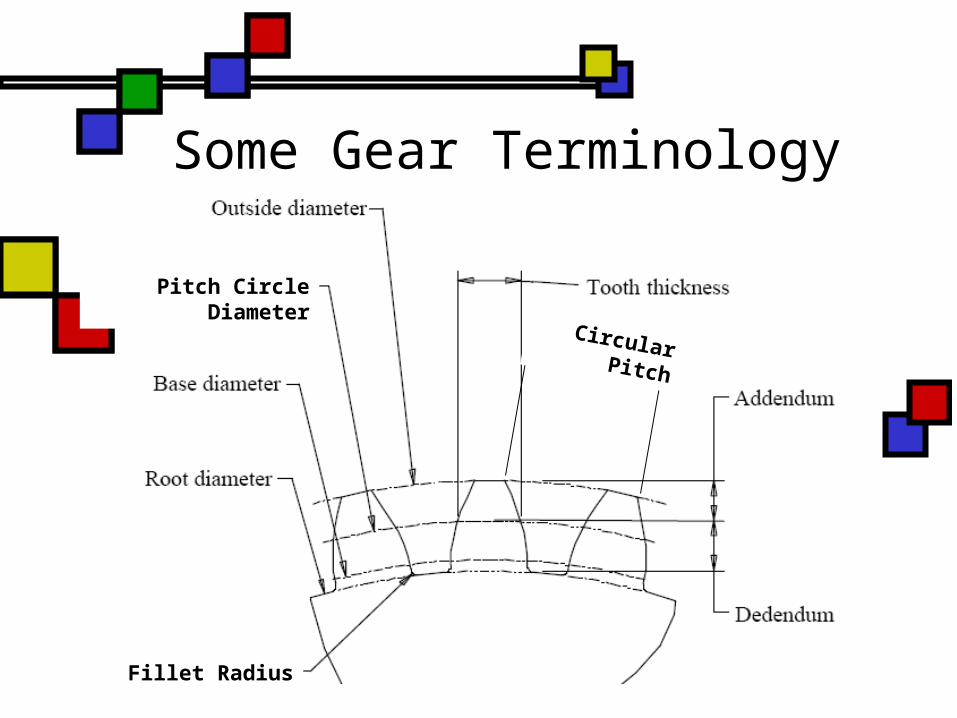
Some Gear Terminology
Pitch Circle Diameter
Fillet Radius
Circular Pitch
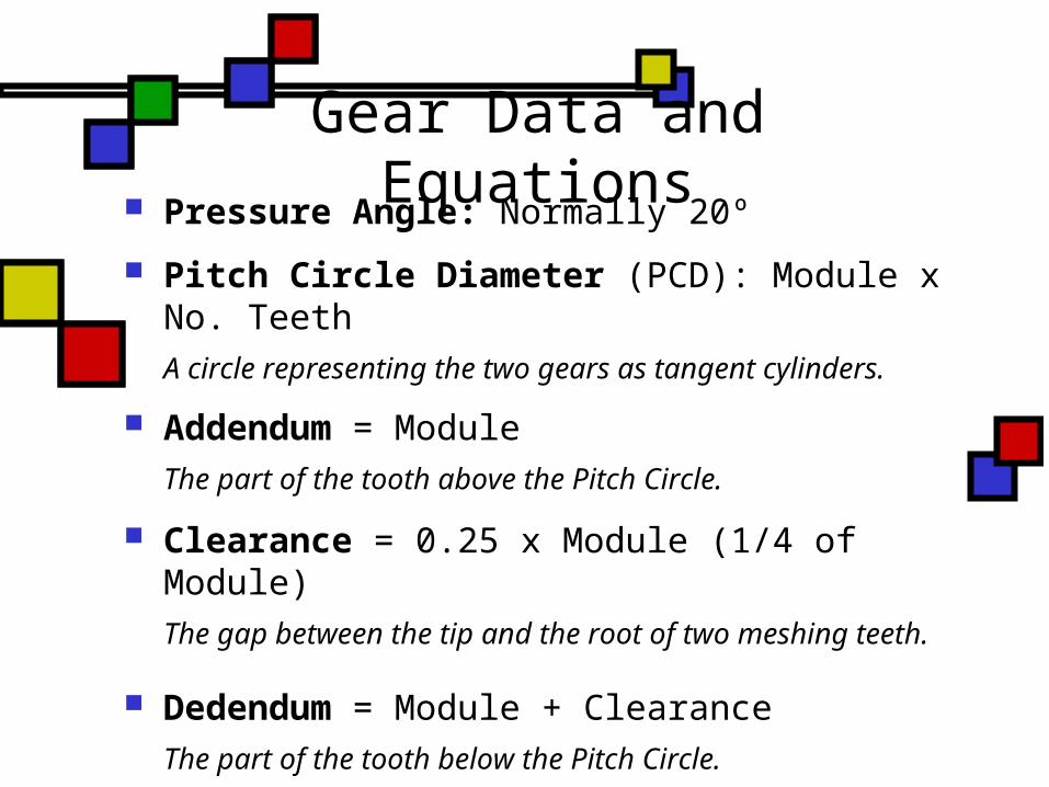
Gear Data and Equations Pressure Angle: Normally 20º
Pitch Circle Diameter (PCD): Module x No. TeethA circle representing the two gears as tangent cylinders.
Addendum = ModuleThe part of the tooth above the Pitch Circle.
Clearance = 0.25 x Module (1/4 of Module)The gap between the tip and the root of two meshing teeth.
Dedendum = Module + ClearanceThe part of the tooth below the Pitch Circle.
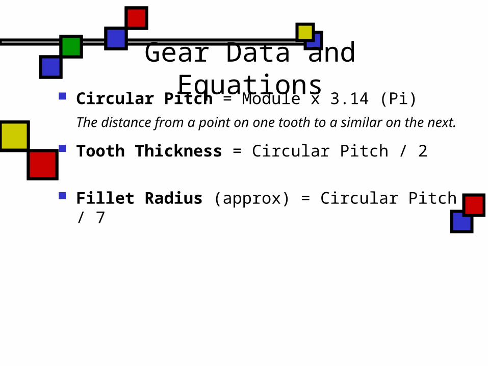
Gear Data and Equations Circular Pitch = Module x 3.14 (Pi)
The distance from a point on one tooth to a similar on the next.
Tooth Thickness = Circular Pitch / 2
Fillet Radius (approx) = Circular Pitch / 7
Spur Gear Calculation & Drawing
The method used here to draw a typical spur gear is called “Unwin’s Construction”. It is also called the “Approximate Method” because it is only produces an Approximate “Involute Curve”.
Tip: When drawing a Gear in AutoCAD – make full use of Layers and Colours.
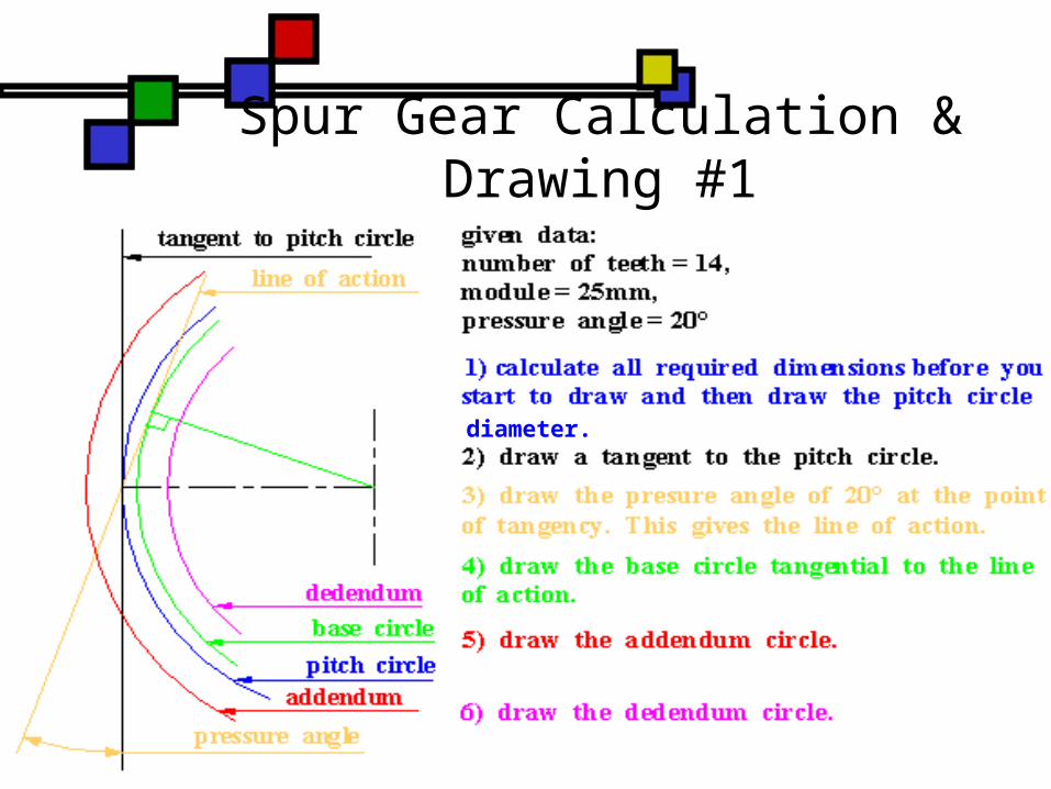
Spur Gear Calculation & Drawing #1
diameter.

Spur Gear Calculation & Drawing #2
a circle
Spur Gear Calculation & Drawing
Now its your Turn ->Draw a Spur gear with the following
details:Module: 2mmNumber of Teeth: 25
Dimensioning to BS308 Standards
Each dimension required should only appear once. There should be no more dimensions than necessary.
Linear Dimensions are normally in millimeters (mm). The symbol may be ommitted provided the drawing carries a statement of the unit used.
Angular Dimensions should be expressed in degrees and minutes, e.g.:
20° 30’
Dimensioning to BS308 Standards
Projection lines and dimension lines should normally be placed outside the outline of the view.
Crossing of projection and dimension lines should be avoided.
Projection lines should start just clear of the outline of the feature and should extend a little beyond the dimension line.
Projection lines should normally be drawn perpendicular to the dimension required.
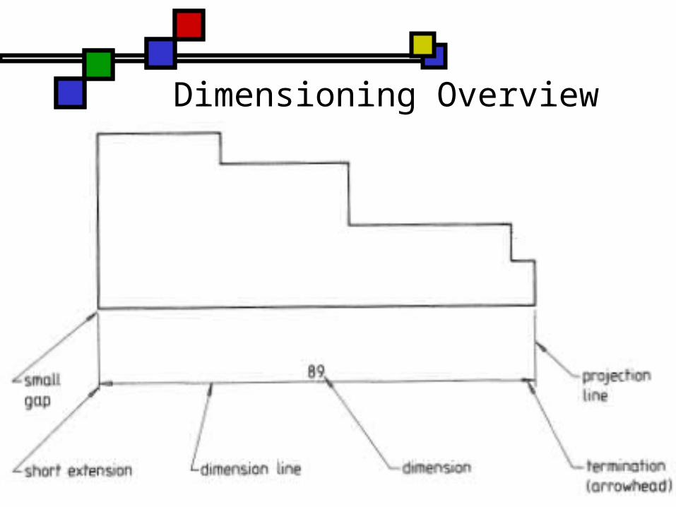
Dimensioning Overview
Dimensioning Overview
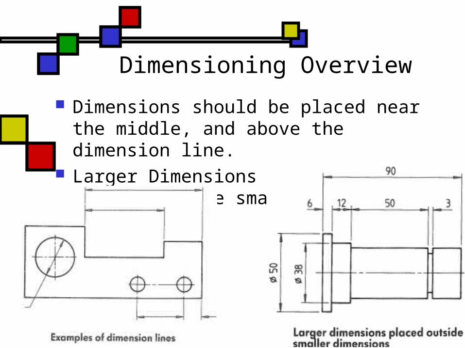
Dimensions should be placed near the middle, and above the dimension line.
Larger Dimensions should be placed outside smaller dimensions.
Dimensioning Methods
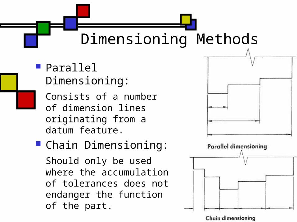
Parallel Dimensioning:Consists of a number of dimension lines originating from a datum feature.
Chain Dimensioning:Should only be used where the accumulation of tolerances does not endanger the function of the part.
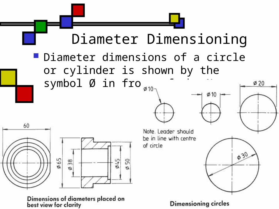
Diameter Dimensioning Diameter dimensions of a circle or
cylinder is shown by the symbol Ø in front of the No.

Radius Dimensioning Radii should be dimensioned by a
dimension line that passes through, or is in line with, the center of the arc.
The dimension line should have one arrowhead only, that which touches the arc.
The symbol R is placed in front of the No.
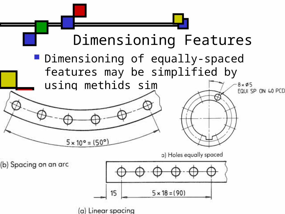
Dimensioning Features Dimensioning of equally-spaced
features may be simplified by using methids similar to below:
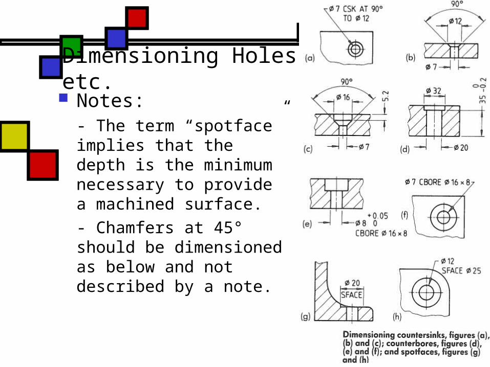
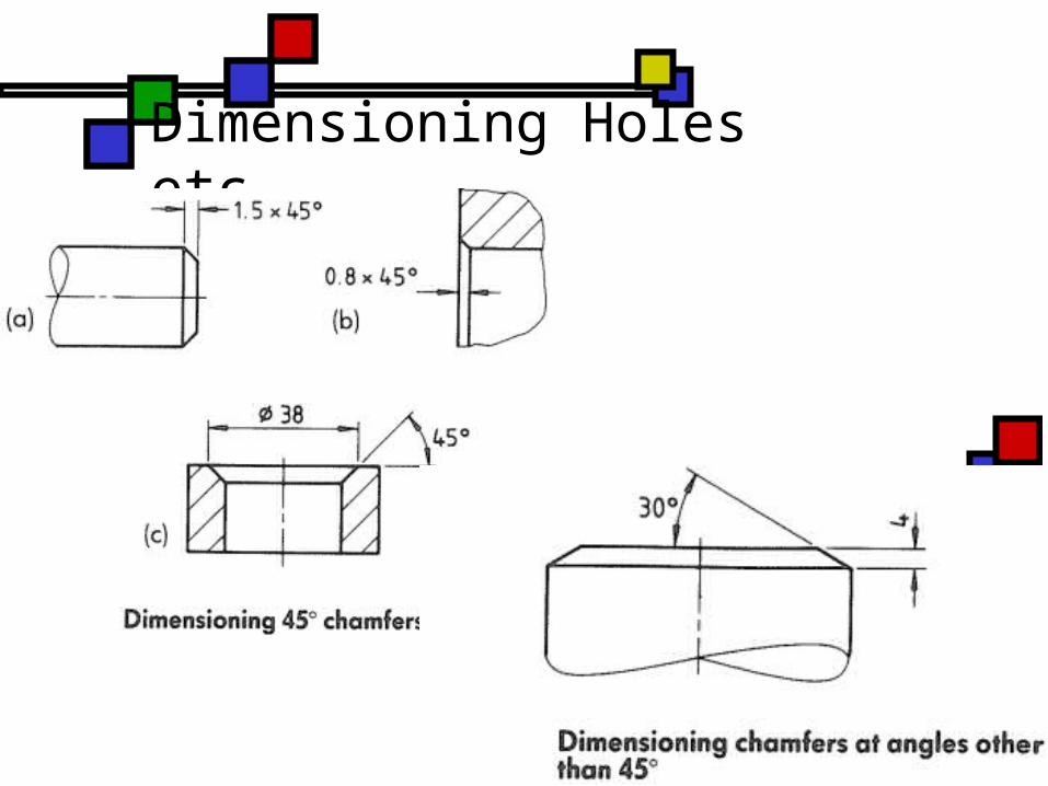
Notes:- The term “spotface” implies that the depth is the minimum necessary to provide a machined surface.- Chamfers at 45° should be dimensioned as below and not described by a note.
Dimensioning Holes etc.
Dimensioning Holes etc.
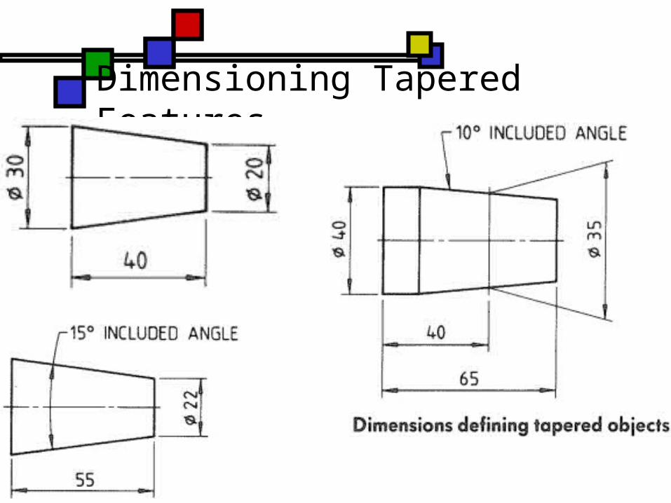
Dimensioning Tapered Features
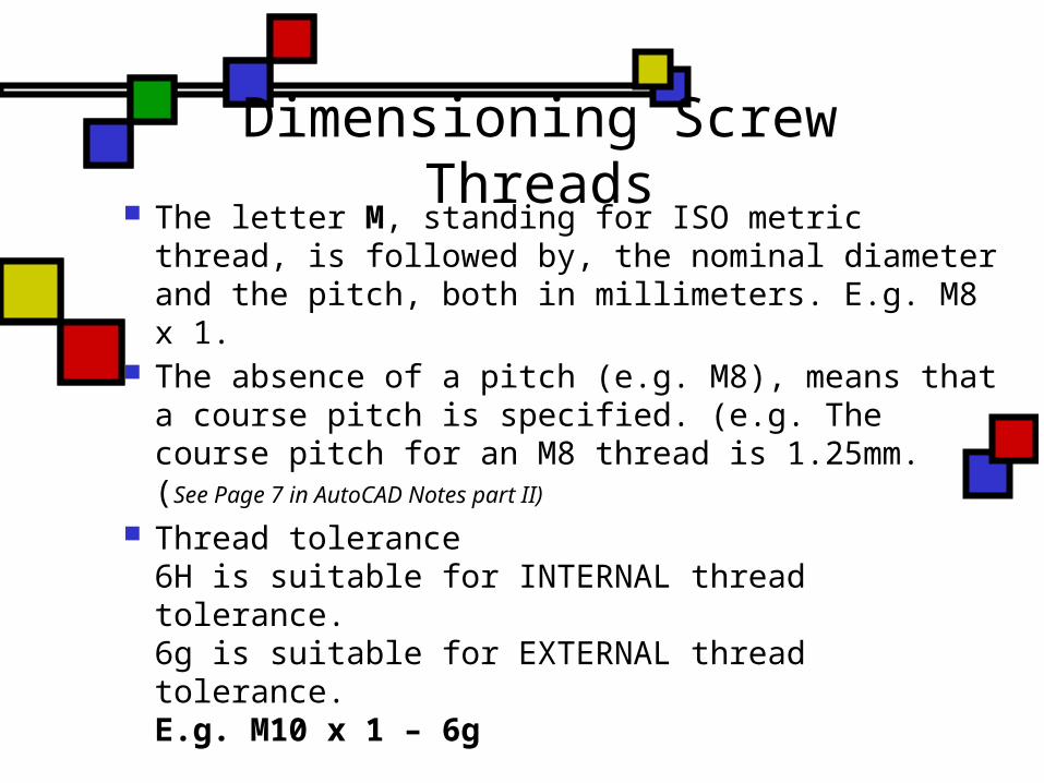
Dimensioning Screw Threads The letter M, standing for ISO metric thread,
is followed by, the nominal diameter and the pitch, both in millimeters. E.g. M8 x 1.
The absence of a pitch (e.g. M8), means that a course pitch is specified. (e.g. The course pitch for an M8 thread is 1.25mm.(See Page 7 in AutoCAD Notes part II)
Thread tolerance6H is suitable for INTERNAL thread tolerance.6g is suitable for EXTERNAL thread tolerance.E.g. M10 x 1 – 6g

Dimensioning External Threads
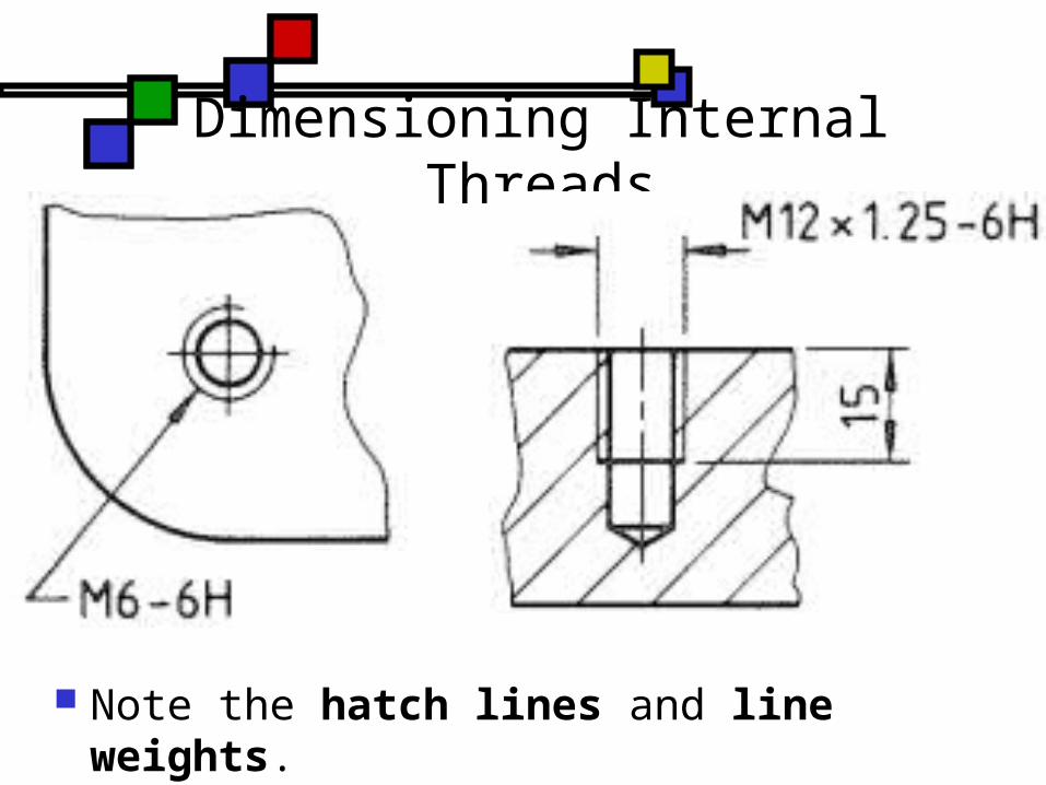
Dimensioning Internal Threads
Note the hatch lines and line weights.
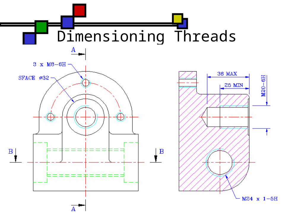
Dimensioning Threads

Typical Dimensioned Drawing
Related Documents