fö CO o < AVSCOM Report No. 76-12 Production Engineering Measures Program Manufacturing Methods and Technology COMPUTER-AIDED DESIGN AND MANUFACTURING FOR EXTRUSION OF ALUMINUM, TITANIUM AND STEEL STRUCTURAL PARTS (PHASE I) VIJAY NAGPAL and TAYLAN ALTAN BATTELLE, Columbus Laboratories 305 King Avenue Columbus, Ohio 43201 March 1976 AMMRC CTR 76-6 W^^c Final Report Contract Number DAAG46-75-C-0054. Approved for public release; distribution unlimited. Prepared for U.S. ARMY AVIATION SYSTEMS COMMAND St. Louis, Missouri 63!66 ARMY MATERIALS AND MECHANICS RESEARCH CENTER Watertown. Massachusetts 02172

Welcome message from author
This document is posted to help you gain knowledge. Please leave a comment to let me know what you think about it! Share it to your friends and learn new things together.
Transcript

fö
CO
o <
AVSCOM Report No. 76-12
Production Engineering Measures Program Manufacturing Methods and Technology
COMPUTER-AIDED DESIGN AND MANUFACTURING FOR EXTRUSION OF ALUMINUM, TITANIUM AND STEEL STRUCTURAL PARTS (PHASE I)
VIJAY NAGPAL and TAYLAN ALTAN BATTELLE, Columbus Laboratories 305 King Avenue Columbus, Ohio 43201
March 1976
AMMRC CTR 76-6 W^^c Final Report Contract Number DAAG46-75-C-0054.
Approved for public release; distribution unlimited.
Prepared for
U.S. ARMY AVIATION SYSTEMS COMMAND St. Louis, Missouri 63!66
ARMY MATERIALS AND MECHANICS RESEARCH CENTER Watertown. Massachusetts 02172
**^
s
! «8:.
n. t
»'''■•'«»TlMI/lMiuilllTT MW j
/} .'i':'l. «iij.j/ S*K!iT
The findings in thit report an not to IM construed « an official Department of the Army position, unless so designated by other authorized documents.
Mention of any treda names or manufacturer« in thit report «hell not be construed as advertising nor at an official indorsement or approval of such products or companies by the United States Government.
DISPOSITION INSTRUCTIONS
Dwtrov tftto ftpott wntn ft it **© Do not ftXur n tt to th« or

AD
AVSCOM Report No. 76-12
Production Engineering Measures Program Manufacturing Methods and Technology
COMPUTER-AIDED DESIGN AND MANUFACTURING FOR EXTRUSION OF ALUMINUM, TITANIUM AND STEEL STRUCTURAL PARTS (PHASED
VIJAY NAGPAL and TAYLAN ALTAN BATTELLE, Columbus Laboratories 505 King Avenue Columbus, Ohio 43201
March 1976
AMMRC CTR 76-6
Final Report Contract Number DAAG46-75-C-0054
Approved for public release; distribution unlimited.
Prepared for
U.S. ARMY AVIATION SYSTEMS COMMAND St. Louis, Missouri 63166
ARMY MATERIALS AND MECHANICS RESEARCH CENTER Watertown, Massachusetts 02172
FOREWORD
This final report on "Computer-Aided Design and Manufacturing for
Extrusion of Aluminum, Titanium, and Steel Structural Parts - Phase I"
covers the work performed under Contract DAAG46-75-C-0054, with Battelle's
Columbus Laboratories, from February 10, 1975 to February 10, 1976.
The project was supported bv the Army Materials and Mechanics
Research Center, Watertown, Massachusetts, and by the U.S. Army Aviation
Systems Command, St. Louis, Missouri. The (AVSCOM) liaison engineer was
Mr. Roger Spangenberg. The technical supervision of this work was under
Mr. Roger Gagne of AMMRC.
* This project has been conducted as part of the U.S. Army Manu-
facturing Methods and Technology Program, which has as its objective the
timely establishment of manufacturing processes, techniques, or equipment
to ensure the efficient production of current and future defense programs.
This program hJS been conducted in the Metalworking Section of
Battelle's Columbus Laboratories, with Mr. T. G. Byrer, Section Manager.
The principal investigators of the program are Dr. Vijay Nagpal, Staff
Scientist, and Dr. Taylan Altan, Research Leader. Other Battelle staff
members have been consulted throughout the program as needed.
In conducting the model-extrusion trials, which represent an
important portion of the Phase-I work, the principal investigators of the
program cooperated with Air Force personnel. The trialu were carried out
using the 700-ton horizontal extrusion press of the Air Force Materials
Laboratory at Wright-Patterson Air Force Base, Ohio. The authors gratefullv
acknowledge the assistance of Messrs. A. M. Adair, V. DePierre, F. Gurney,
and M. Myers in conducting these trials.
wsar.1

PROGRAM SUMMARY
The overall objective of this manufacturing-technology program was
to develop practical computer-aided design and manufacturing (CAD/CAM)
techniques for extrusion of aluminum alloys, steels, and titanium alloys.
It is expected that the application of CAD/CAM in extrusion will expand
the capabilities of the extrusion process and reduce the cost of extruding
and firishing structural components used in manufacturing military aircraft.
The Phase-I work, reported here, was devoted to develop the CAD/CAM
method for extruding a modular shape of rectangular cross section using
lubricated, streamlined dies. The results, reported here, indicate that the
objectives of Phase-I work has been fully achieved.
The success of any manufacturing-development program depends mainly
upon two factors:
(1) The technical quality and the usefulness of the
development work
(2) The acceptance, the application, and the use of
the results developed in the program, by the
industry and others active in that field.
Therefore, in addition to fulfilling the technical requirements of Phase-I work,
Initial contacts were made with companies extruding aluminum and titanium alloys,
in order to emphasize the practical and industrial aspects of these program results.
Introduction of CAD/CAM in Extrusion
Large numbers of extruded aluminum, titanium, and steel components
are used in the manufacture and assembly of military hardware. Most of these
components are extruded by conventional hot extrusion techniques. Although
the extrusion process has been a viable manufacturing process for more than a
generation, with the exception of glass lubrication in high-temperature extru-
sion, hardly any improvements have been made. Extrusion technologv is still
based largely upon empirical cut-and-trv methods which result in the high cost
of extruded products. Most of the tool design and manufacturing work
for extrusion is still done by the intuitive and empirical methods. Therefore,
extrusion die design and manufacturing is still considered an art rather than
a science. In this respect, the state of the art in the extrusion technologv
ii
is verv similar to that of other metal-forming processes. The scientific and
engineering methods, successfully used in other engineering disciplines, have
not been utilized in extrusion. This situation can be explained bv the
inherent complexity of the extrusion process. The dlfficult-to-predict metal
flow, the simultaneous heat generation and transfer which takes place during
the process, the friction at the material-tool interfaces, and the metallurgical
variations, n:ake the extrusion process difficult to analyze from the engineering
point of view. However, recently, computer-aided techniques for analyzing and
simulating metal-flow and deformation mechanics have been developed and proven.
The application of these techniques along with advanced numerical machining
(NC) technology allows the practical use of CAD/CAM in extrusion technology.
The Phase-I work illustrated the feasibility of applying CAD/CAM in
extrusion-die design and manufacture, and in process planning.
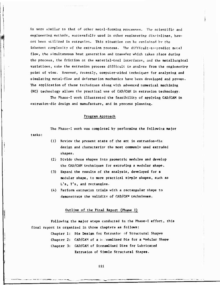
Program Approach
The Phase-I work was completed by performing the following major
tasks: ■
(i) Review the present state of the art in extrusion-die
design and characterizf the most commonly used extruded
shapes.
(2) Divide these shapes into geometric modules and develop
the CAD/CAM techniques for extruding a modular shape.
(3) Expand the results of the analysis, developed for a
modular shape, to more practical simple shapes, such as
L's, T's, and rectangles.
(4) Perform extrusion trials with a rectangular shape to
demonstrate the validity of CAD/CA" techniaues.
Outline of the Final Report (Phase I)
Following the major steps conducted in the Phase-I effort, this
final report is organized in three chapters as follows:
Chapter 1
Chapter 2
Chapter 3
Die Design for Extrustor of Structural Shapes
CAD/CAM of a si .eamlined Die for a Modular Shape
CAD/CAM of Streamlined Dies for Lubricated
Extrusion of Slmole Structural Shapes.
ill

Each chapter can be read separately, without having to go through the entire
report, to find information related to any of the malor tasks conducted in
this program. Thus, the use and readability of this final report is enhanced.
1 Chapter 1 sunmarizes the state of the art on die design for extruding
| structural shaoes. This chapter also reviews (a) the conventional nonlubricated
extrusion of aluminum alloys, (b) the recent development efforts on lubricated
extrusion of aluminum alloys, and (c) the technology and die design for extruding
steels, titanium alloys, and high-temperature alloys.
Chapter 2 describes the work conducted toward applying CAD/CAM tech-
niques to the extrusion of a modular shape, which was selected to be an ellipse,
approximating a rectangle. This chapter also Includes the analysis and simula-
tion of the extrusion process as well as a description of the NC machining tech-
niques suggested for manufacturing the extrusion dies.
Chapter 3 describes the application of CAD/CAM techniques to extrude
simple structural shapes, such as L's, T's, rectangles, and triangles. Numerical
techniques are given for lubricated extrusion (a) to define the surface of
"streamlined" dies", and (b) to manufacture these dies bv a combination of
Numerical Control (NC) machining and Electro-Discharge Machining (EDM). Chapter
3 also describes the extrusion trials conducted with a rectangular shape, and
discusses the comparison of predictions made by CAD/CAM techniques with the
measurements made during the extrusion trials. The results indicate that the
CAD/CAM techniques, developed in this Phase-I work, are capable of predicting
extrusion pressures and metal flow in ''streamlined extrusion" with acceptable
accuracy.
Chapter 3 summarizes the Phase-I work, Including the most slgnlflcanc
aspects of the technical effort conducted in this program.
iv

: -
CHAPTER I
"DIE DESIGN FOR EXTRUSION OP STRUCTURAL SHAPES"
*
"S
R
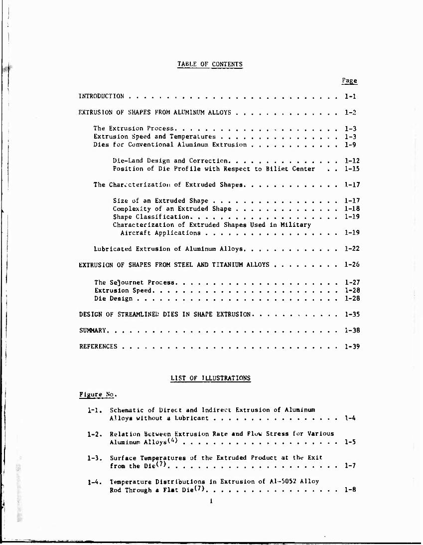
TABLE OF CONTENTS
Page
INTRODUCTION 1-1
EXTRUSION OF SHAPES FROM ALUMINUM ALLOYS 1-2
The Extrusion Process , 1-3 Extrusion Speed and Temperatures 1-3 Dies for Conventional Aluminum Extrusion 1-9
Die-Land Design and Correction 1-12 Position of Die Profile with Respect to Billet Center . . 1-15
The Characterization of Extruded Shapes 1-17
Size of an Extruded Shape 1-17 Complexity of an Extruded Shape 1-18 Shape Classification 1-19 Characterization of Extruded Shapes Used in Military
Aircraft Applications 1-19
Lubricated Extrusion of Aluminum Alloys 1-22
EXTRUSION OF SHAPES FROM STEEL AND TITANIUM ALLOYS 1-26
The Se^ournet Process 1-27 Extrusion Speed 1-28 Die Design 1-28
DESIGN OF STREAMLINED DIES IN SHAPE EXTRUSION 1-35
SUMMARY 1-38
REFERENCES 1-39
LIST OF ILLUSTRATIONS
Figure No.
1-1. Schematic of Direct and Indirect Extrusion of Aluminum Alloys without a Lubricant 1-4
1-2. Relation Between Extrusion Rate and Flow Stress for Various Aluminum Alloy.-,'■••) 1-5
1-3. Surface Temperatures of the Extruded Product 'it the Exit fro« the Die<?> 1-7
1-4. Temperature Distributions in Extrusion of Al-5052 Alloy Rod Through a Plat Dle<7> 1-8
i

LIST OF ILLUSTRATIONS (Continued)
Figure No. Page
(13-15) 1-5. Various Types of Extrusion Dies for Aluminum Alloys . 1-10
1-6. Correction of Die Land by Filing on Relief or Choke(. . . 1-13
1-7. Correction of the Extrusion Profile by Filing Relief and Choke'15) 1-13
(21) 1-8. Variation of Die Und Length With Section Thickness ... 1-14
1-9. Examples for Positioning the Die Opening With Iespect to Billet Axis*22) 1-16
' 7 5) 1-10. Definition of Size by Circumscribing Circle Diameter (CCt>/ ' 1-18
(25) 1-11. Classification of Shapes into Various Groups 1-20
1-12. Structural Shapes Commonly Used in Military Aircraft .... 1-21
1-13. Conical-Flat Die Design Used in Lubricated Extrusion of Two L-Sections from Aluminum Alloys'*7' 1-23
1-14. Possible Die Designs for Lubricated Extrusion of a Bar With Two Ribs*4) 1-25
1-15. Hot intrusion Setup Using CL s Lubrication 1-27
1-16. Flat-Faced Die Used for Extruding Titanium Alloys T1-155A and C135-AMo(38) 1-30
1-17. Modified Flat-Faced Die Design Used for Extruding Titanium Alloys with Glass Lubricant**8) 1-31
(44) 1-18. Curved Die Used for Extruding Berylliumv ' 1-33
..,-.. e,.. _(*6) 1-19. Conical Die Used for Extruding TZM "T" Shapes 1-34
1-20. Possible Die Designs for Extrusion of Aluminum, Steel and Titanium Alloys 1-37
ii
CHAPTER I
"DIE DESIGN FOR EXTRUSION OF STRUCTURAL SHAPES"
ABSTRACT
This chapter summarizes the state of the art on die design for
extruding structural shapes. The conventional dry extrusion of aluminum
shapes is discussed and the limited amount cf information, available on
lubricated extrusion of aluminum alloys, is summarized. The extrusion
technology and die design for steels, titanium, anc" high-temperature alloys
are critically reviewed. Past work on extrusion technology indicates that,
with improved die design, lubricated extrusion of hard-aluminum alloy shapes
could become practical and the extrusion of high-temperature alloys can be
&i?;rjfjcantly improved.
INTRODUCTION
In recent years, a considerable amount of work has been conducted
on the improvement of the extrusion process for producing shapes from
aluminum, steel, titanium, and high-temperature alloys. This work
has resulted in the development of some new extrusion techniques, such as
extrusion uf steel and high-strength alloys with glass lubrication. However;
the overall extrusion technology still remains to be largely based on
empirical cut-and-dry methods. Most of the extrusion die design and manufac-
turing work is still considered an art rather than a science. This situation
can be explained by the inherent complexity of the extrusion process. The
difficult to predict metal flow, the simultaneous heat generation and transfer
which takes place during the process, the friction at the material-tool
1-2
interfaces, and the metallurgical variations make the extrusion process very
difficult to analyze from an engineering point of view. Consequently, there
remains still considerable development work to be done in order to upgrade
the extrusion technology to the level of an advanced manufacturing process,
for producing sound parts at moderate costs.
Current practices followed for extruding aluminum alloys are quite
different from those used for extruding steel, titanium, and high-
temperature materials. Therefore, the extrusion of aluminum is discussed
separately and the limited amount of information available on lubricated
extrusion of aluminum is reviewed. This subject is of special interest to
this project since the project has the primary objective to develop computer-
aided die design and manufacturing techniques for lubricated and streamlined
extrusion of aluminum alloys, titanium alloys, and steels. After reviewing
the extrusion technology for steels and titanium alloys, the chapter presents
some suggestions regarding the approach to die design. These suggestions
are evaluated in detail later in the program.
In preparing the present review, it is assumed that the reader is (1 2)
familiar with the general aspects of the extrusion processes. ' The
information, summarized in this chapter, relates particularly to process
variables and to die design in extrusion.
EXTRUSION OF SHAPES FROM ALUMINUM ALLOYS
A variety uf aluminum alloys (1000 to 7000 series) are extruded
and find large numbers of commercial and military applications. Among all
these alloys, the high-strength aluminum alloys (2000 and 7000 series) are
most widely used for aircraft applications. Other alloys, such as 1100,
3003, 6061, 6062, 6063, and X6463, are used for manufacturing goods for a
variety of applications, such as construction, household appliances, and (3)
transportation.
1-3
The Extrusion Process
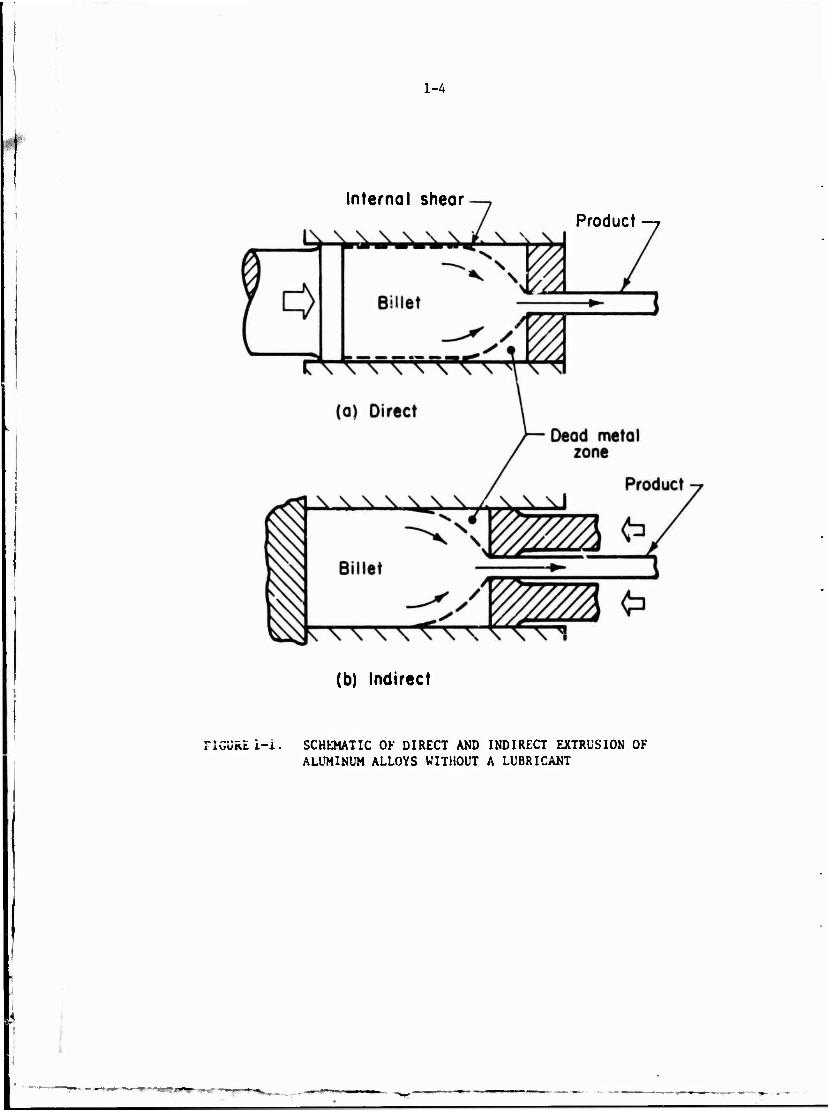
The two most significant extrusion processes for aluminum are the
direct and indirect extrusion, and these are schematically illustrated in
Figure 1-1. With aluminum, lubricant is not normally used. The extru-
sion method, which uses no lubrication between the billet, the container,
and the die, is used to produce complex shapes vith excellent surface
finish and close-dimensional tolerances. These shapes are considered net
extrusions and they are usäd in as-extruded form, after necessary straight-
ening and surface-costing operations. '
In nonlubricated extrusion of aluminum, the billet is extruded
through a fiat-faced, or shear-faced die. As the pressure is applied to
the end of the billet, internal shearing occurs across the planes within
the billet, and fresh metal is forced out through the die orifice. This
fresh metal accounts for the bright finish obtained on extruded aluminum
shapes. With this technique, however, very high extrusion forces are
required because of internal shearing between the flowing and the stationary
metal along the container surface and at the die corners, Figure l-l. The
energy dissipated by internal shearing, or redundant work, represents energy
that is converted Into heat, and results in a gradual increase of the product
temperature as the extrusion proceeds. If not controlled, this adiabatic
heating can be sufficient to cause hot shortness and melting in the extruded
material.
Extrusion Speed and Temperatures
In order to increase the production rate in extrusion, it is
desirable to achieve as high an extrusion ratio as possible. Therefore,
with havd aluminum alloys, the maximum possible billet preheat temperatures are
utilised. This combination of high-extrusion ratio, high-starting billet
temperature, and the danger of overheating due to redundant work, neces-
sitates very low extrusion speeds for extruding a sound product. Thus,
a ram speed of 1/2 inch/minute is quite common. With a typical extrusion
ratio of 40:1, exit speeds of the extrusion can be in the order of 2 to 4
I
1-4
Internal shear Product
(b) Indirect
FIGURE i-I. SCHEMATIC OF DIRECT AND INDIRECT EXTRUSION OF ALUMINUM ALLOYS WITHOUT A LUBRICANT

..
1-5
feet/minute. Figure 1-2 shows the range of extrusion speeds, at exit, used (4)
for different aluminum alloys. It is of interest to note that for soft
alloys the speeds are re. mably high; however, for hard alloys, such as
2024 and 7075, extrusion rates are quite low. Consequently, the use of
lubrication in extruding high-strength alloys can be expected to increase
the extrusion rate and to reduce extrusion costs. However, lubrication
cannot offer any significant advantages in extruding the soft alloys.
«o CO «0 lOO flO« Strtll.KH 'm*
FIGURE 1-2. RELATION BETWEEN EXTRUSION RATE AND FLOW STRESS FOR VARIOUS ALUMINUM ALLOYS***

1-6
By far, the greater proportion of all Aluminum extrusions consists
of heat-treated alloys and all of these have a critical temperature asso-
ciated with the presence of low-melting intermetallic compounds that restricts
the permissible extrusion temperatures and speeds. Because of the slow
speed of extrusion, the tooling temperature is maintained close to, about 50
C to 100 C below, that of the billet, so that chilling of the billet is
minimized. Akeret conducted theoretical and practical studies of temperature
distribution in the extrusion of aluminum alloys under conditions in which the
container and tools were initially below, equal to, or above the initial
billet temperature. He deduced that, for the particular experimental condi-
tions employed, the rise of temperature under adiabatic conditions would be
about 95 C. For practical purposes, it can be estimated that, in extruding
high-strength alloys, the maximum temF'^ature rise likely to be encountered
will not exceed 100 C. For the soft alloys where lower specific pressures
are required, the temperature rise under normal production conditions is not
likely to exceed 50 C. 5'
At Battelle's Columbus Laboratories, computer programs have been
developed for predicting temperatures in extrusion of rods and tubes from (7 8)
various materials. ' As seen in Figure 1-3, based on theoretical predic-
tions as well as on experimental evidence, the product temperature increases
as extrusion proceeds. The temperature at the product surface is higher than
the temperature at product center. This is illustrated in Figure 1-4 for
given extrusion conditions. Thus, it is seen that the surface temperature of
the product may approach the critical temperature where hot shortness may
occur, only towards the end of the extrusion cycle. The temperature of the
extruded product, emerging from the die, is one of the essential factors
influencing the product quality. Therefore, an ideal procedure for estab-
lishing the maximum speed of extrusion at all times would be to measure this
temperature and to use it for controlling the ram speed. This procedure was (9)
proposed in an early patent, but the problem of obtaining an accurate and
continuous temperature measurement of the extruded product remains unsolved.
Methods for measuring the product temperature by using various types of
contact thermocouples, or by radiation pyrometry, did not prove to be
practical.

1-7
520- Ram Velocity V=74.4 inymln Al 5052
Vs 74.4 in./min Al 1100
V-5.9 in./min Al MOO
± 2 3 4«
Ram Displacement, in.
FIGURE 1-3. SURFACE TEMPERATURES OF THE EXTRUDED PRODUCT AT THE EXIT FROM THE DIE (Reduction - 5:1, Billet Diameter « 2.8 in., Billet Length - 5.6 in., Initial Billet and Tooling Temperature - 440 C)(7)
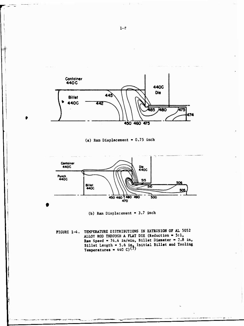
1-8
Container 440 C
Billet
* 440C
474
450 460 475
(a) Ram Displacement - 0.75 inch
(b) Ram Displacement - 3.7 inch
FIGURE 1-4. TEMPERATURE DISTRIBUTIONS IN EXTRUSION OP AL 5052 ALLOY ROD THROUGH A FLAT DIE (Reduction - 5:1, Ram Speed - 74.4 in/min, Billet Diameter - 2.8 in, Billet Length - 5.6 in. Initial Billet and Tooling Temperatures • 440 C)(')

1-9
(10) . , Laue was the first to propose a system for isothermal extrusion
in which the ram speed variation, necessary tu keep the product temperature
within the required limits, was pre-established. In presses, designed to
operate on this principle, the working stroke is divided into zones, each
having a preset speed. In a press used for extruding the high-strength alloys,
a saving of 60 percent in time was claimed. This saving would certainly be
less in the case of more easily extruded alloys. According to Fernback, to
make full use of the isothermal-extrusion principle, it would be necessary to
predetermine, by trial and error, a large number of speed programs for extruding
different alloys and products.
In extrusion of aluminum alloys, temperature variations in the
emerging product can be reduced by imposing a temperature gradient in the
billet. The hot end of the billet is entered into the container such that
it is extruded first, while the temperature of the cooler end increases during
the extrusion. This practice is not entirely satisfactory because of the
relatively high-thermal conductivity of aluminum alloys, so that if any delays
occur in a programmed sequence, the temperatures in the billet tend to become
uniform throughout the billet length. A better method is to water quench the
back end of the billet while transferring it from the furnace and the press-
feed table to the container. Neither method is found to be accurate and
: has (12)
reproducible. Another approach that has been used to increase the extru-
sion speed is to use water-cooled dies.
For controlling and predicting the variation of the ram speed during
extrusion, it may te useful to use computer simulations tc predict the tempera- (7 8)
ture rise during the process. ' The purpose of this computer-aided speed
control would be to have maximum extrusion speeds with minimum variation in
temperature in the extruded product.
Dies for Conventional Aluminum Extrusion
There are four general designs of flat-faced dies for extruding
aluminum, as shown in Fipure 1-5.
(1) Solid shape
(2) Porthole
(3) Bridge
(4) Baffle or feeder plate.

1-10
o
"1 <x > ^ ML
o
4 : ?r \
r" X. ../
(a) Sjlld-Shape Die (13)
(b) Porthole Die With Tooling Assembly and E):ample Shapes Extruded Through Such a Die( '
(c) Bridge Die
Flow
I»
Backer
Die-/ Baffle or Welding Plate
(d) Baffle, or Feeder Plate Die (14)
FIHURE 1-5. VARIOUS TYPES OF EXTRUSION DIES FOR ALUMINUM ALLOYS (13-15)
M)»1) ...—»-
1-11
The solid-shape dies are primarily used fur extruding solid shapes. These dies
are made by machining an opening of the desired shape in the die block as shown
in Fipure l-5a. The porthole die design, shown in Figure l-5b, has porthole
openings in the top face of the die from which material is extruded into two
or more segments, and then, beneath the surface of the die, welded and forced
through the final shape configuration to form a part. The tubular portion of
the extruded shape is formed by a mandrel attached to the lower side of the
top die segment. This provides a fixed support for the mandrel and a contin-
uous hole in the extruded part. Figure l-5b shows typical complex parts that
can be made through the use of a porthole type arrangement.
Bridge dies are quite similar to the porthole dies and are also used
for extruding hollow products. The "bridge" which divides the metal extends
into the container, Figure l-5c. Compared to porthole dies, the bridge dies
are less rigid. However, the removal of the extrusion, left in the container
at the completion of the extrusion cycle, is more difficult with porthole dies
than with bridge dies.
Another interesting type of die design, shown in Figure l-5d, is
the so-called baffle or feeder-plate die, which is used to serve several
purposes. The feeder plate provides a uniform feed of metal into the cavity
of the die, which induces flow control and assists in maintaining the contour
of the extruded section. It also permits the next billet to partially weld
itself to the material in the cavity, ensuring a straight run out for the
next extrusion. This method helps to extrude straighter extrusions and to
reduce scrap. These feeder plates are used for single and multi-hole dies
of all sizes and shapes. Other die designs used for specific products are
illustrated in References 14 and 15.
In conventional unlubricated extrusion with flat-faced dies, the
material always shears against itself and forms a dead, or stationary zone,
at the die face, Figure 1-1. The formation of the dead rone minimizes the
overall rate of energy dissipation, but in general, does not give, in
extrusion of shapes, uniform metal flow at the die exit. Nonuniform metal
flow can result in twisting and bending of the emerging product. To prevent
this, the flow rate is controlled through proper design of die land and by (16)
proper positioning of die cavity with respect to the billet center.

1-12
Die-Land Design and Correction
There is a general agreement that longer die lands improve the
tolerances and straightness of the extruded products. However, the extrusion
load increases with increasing length of the die land. Thus, the die land
must be designed to give uniformly strained product within desired tolerances
and without excessive extrusion pressure.
In lubricated cold-rod extrusion, Keegan gives sums approximate (18} (19)
rules for estimating the land length in dies. Wilson and Feldmann
also recommend certain land lengths. Sieber(-O) suggests that in axisynmetric
extrusion, there is an optimum land length which is given by the following
equation:
L =• 1.2 to .8/d e
where L ■ land length
d *' diameter at the land.
In shape extrusion, unlike in rod or tube extrusion, die land length
is changed to slow down or to speed up metal flow. According to Bello,
with shear-faced dies, the flow can be enhanced by filing a relief bearing or
can be slowed down by filing a choke surface on the die land, as seen in
Figure 1-6. The shape of the extruded section can be modified bv filing choke
and relief on the die lend, as shown in Figure 1-7. In Figure l-7a, the metal
at the outside of the right leg flows faster than that inside. Therefore, with
the die-land corrections indicated in Figure l-7b, the right leg will tend to
go toward the inside. A similar but reverse situation exists in Figures l-7b
and l-7d.
In the practical design of the die land for extrusion ot aluminum
shapes, the land is varied in length according to section width, in order to
obtain uniformity of flow. As shown in Figure 1-8, the thin section is (21)
provided with less land than the thicker section. An empirical guideline
is to keep the land length equal to 1 to 2 times the section thickness. (22)
Another empirical relation, proposed by Matveev and Zhuravski, is to make
the effective length of the die land, at the various portions of the die
opening profile, Inversely proportional to the specific perimeters of these

1-13
Flow *~
FILE ON RELIEF
TO SPEED UP FLOW
Flow
(a)
File on choke to slow down flow
FIGURE 1-6. CORRECTION OF DIE LAND BY FILING ON RELIEF OR CHOKE (15)
Extrusion Extrusion
Rtiieve inside beoring
Choke outside bearing
Leg in
(b)
(0
Choke inside btoring
Relieve outside bearing
(d)
FIGURE 1-7. CORRECTION OF THE EXTRUSION PROFILE BY FILINC RELIEF AND CHOKK Mb)
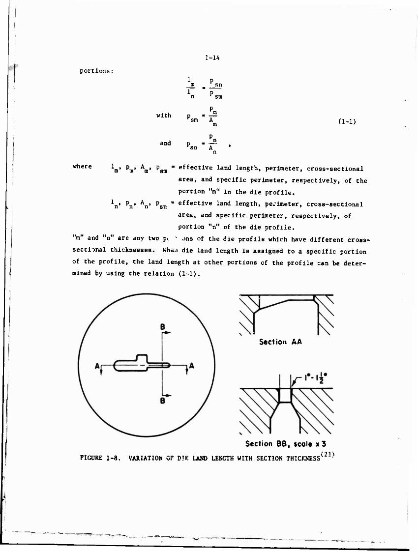
1-14 '
portions:
sn
SIT)
with m sm (1-1)
and n Hsn A
n
where 1^, pm> Am> p^ - effective land length, perimeter, cross-sectional
area, and specific perimeter, respectively, of the
portion "m" in the die profile.
*n' Pn* An' Psn " effective land length, perimeter, cross-sectional
area» and specific perimeter, respectively, of
portion "n" of the die profile,
"m" and "n" are any two p.. k ons of the die profile which have different cross-
sectional thicknesses. Whta die land length is assigned to a specific portion
of the profile, the land length at other portions of the profile can be deter-
mined by using the relation (1-1).
Section A A
Section BB, scole x3
FIGURE 1-8. VARIATION Or DIE LAND LENCTH WITH SECTION THICKNESS*21^
■
—--v. - j'<r ■ •« -
1-15
(22) As suggested by Perlin, the relation (1-1) cannot be true for
all shapes, because it does not take into account the position of the die
opening with respect to the center of the billet. ;«ioreover, the determina-
tion of the specific perimeters is often arbitrary. However, this relation
may be used as a first approximation in extruding shapes for which the center
of gravity of the profile can be made to coincide with the center of the
billet.(22)
Analytically, die-land design for extruding shapes has not been
treated extensively. The only treatment is due to Scrutton, et al., ' who
proposed criteria for die-land design, based on the distribution of tempera-
ture and metal flow in extrusion. According to these authors, the local
length of the die land depends on the reduction; considered in a radial plane,
for any given extrusion shape through shear-faced dies. Their work, however,
is based on many assumptions which are questionable. More theoretical and
experimental effort is needed to provide a scientific basis for die-land
design.
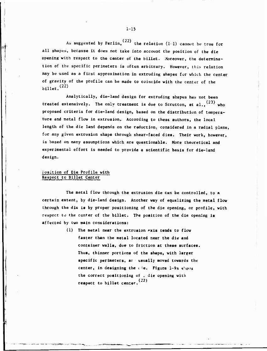
Position of Die Profile with Respect to Billet Center
The metal flow through the extrusion die can be controlled, to a
certain extent, by die-land design. Another way of equalizing the metal flow
through the die ia by proper positioning of the die opening, or profile, with
respect to the center of the billet. The position of the die opening is
affected by two main considerations:
(1) The metal near the extrusion »xis tends to flow
faster than the metal located near the die and
container walls, due to friction at these surfaces.
Thus, thinner portions of the shape, with larger
specific perimeters, ar usually moved towards the
center, in designing the a (e. Figure l-9a s'iows
the correct positioning of „ die opening with (22)
respect to billet center.

1-16
Product shape
Billet -
Correct position Incorrect position
(a) Correct and Incorrect Positioning of Die Opening (22)
Billet
Circumscribing circle
Product shape
P - Center of Gravity of the Profile
Q ■ Center of Circumscribing Circle
R - Center of the Billet
(b) Relative Positioning of Center of Gravity of the Shape,
Circumscribed Circle, and Billet
FIGURE 1-9. EXAMPLES FOR POSITIONING THE DIE OPENING WITH RESPECT TO BILLET AXIS(22)
1-17
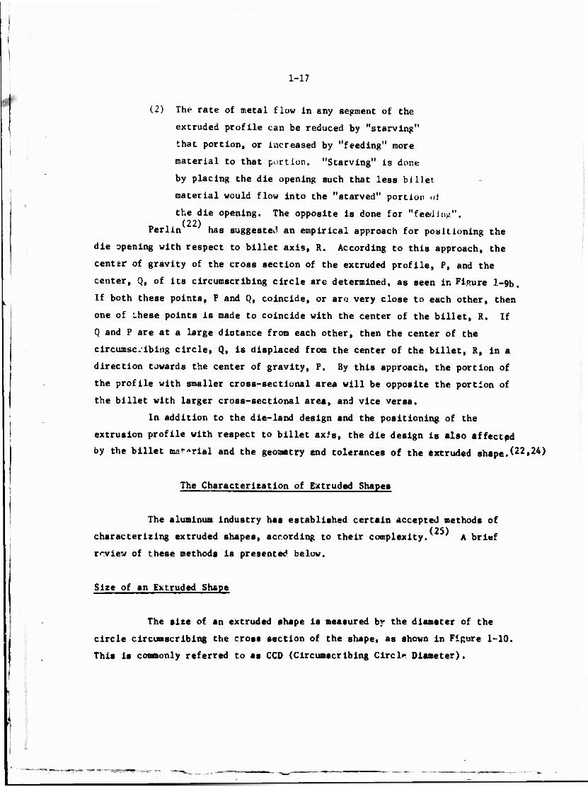
(2) The rate of metal flow in any segment of the
extruded profile can be reduced by "starving"
that portion, or increased by "feeding" more
material to that portion. "Starving" is done
by placing the die opening such that less billet
material would flow into the "starved" portion at
the die opening. The opposite is done for "feeding". (22)
Perlin has suggested an empirical approach for positioning the
die opening with respect to billet axis, R. According to this approach, the
center of gravity of the cross section of the extruded profile, P, and the
center, Q, of its circumscribing circle are determined, as seen in Figure l-9b.
If both these points, P and Q, coincide, or ar« very close to each other, then
one of these points is made to coincide with the center of the billet, R. If
Q and P are at a large distance from each other, then the center of the
circumscribing circle, Q, is displaced from the center of the billet, R, in a
direction towards the center of gravity, P. By this approach, the portion of
the profile with smaller cross-sectional area will be opposite the portion of
the billet with larger cross-sectional area, and vice versa.
In addition to the die-land design and the positioning of the
extrusion profile with respect to billet axJs, the die design is also affected
by the billet material and the geometry end tolerances of the extruded shaped22»24)
The Characterization of Extruded Shapes
The aluminum industry has established certain accepted methods of (25)
characterizing extruded shapes, according to their complexity. A brief
review of these methods is presented below.
Size of an Extruded Shape
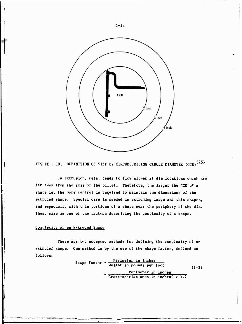
The size of an extruded shape is measured by the diameter of the
circle circumscribing the cross section of the shape, as shown in Figure 1-10.
This is commonly referred to as CCD (Circumscribing Circl* Diameter).
1-18
FIGURE 1 10. DEFINITION OF SIZE BY CIRCUMSCRIBING CIRCLE DIAMETER (CCD) (25)
In extrusion, metal tends to flow slower at die locations which are
far away from the axis of the billet. Therefore, the larger the CCD of a
shape is, the more control is required to maintain the dimensions of the
extruded shape. Special care is needed in extruding large and thin shapes,
and especially with thin portions of a shape near the periphery of the die.
Thus, size is one of the factors describing the complexity of a shape.
Complexity of an Extruded Shape
There are twc accepted methods for defining the complexity of an
extruded shape. One method is by the use of the shape factor, defined as
follows:
Shape Factor - Perimeter in inches
Weight in pounds per foot
Perimeter in inches Cross-section area in inches2 x 1.2
(1-2)

1-19
This factor Is a measure of the amount of surface that is generated per pound
of metal extruded. The shape factor affects the production rate and the cost
of manufacturing and maintaining the dies. It is used by many extruders as
a basis for pricing and gives the designer a means of comparing the relative
complexity of alternate designs.
The other measure of shape complexity is the classification of the
extruded shapes into different groups, based on the difficulty in extruding
them.
Shape Classification
According to this classification, extruded shapas are divided into (25)
the following three major groups:
(J) Solid shapes
(2) Hollow shapes
(3) Semi-hollow shapes, an Intermediate group between
"pure" solids and hollows.
A simple example for each of these three groups is given in Fipure 1-11.
Characterization of Extruded Shapes Used in Military Aircraft Applications
Structural shapes used in the aircraft industrv are usually extruded
from high-strength aluminum alloys, 2000 and 7000 series, and have usually L,
I, T, U, or H type cross sections. Some extruded shapes from 2024 and 7075 alu-
minum alloys, which are used in military aircraft, are given in Figure 1-12.
These shapes are only representative examples of many other structural extrusions
used in military airplanes and helicopters.
All the shapes shown in Figure 1-12 can be visualized as being made
up of rectangular blocks. Thus, it should be possible to treat these shapes
with the help of a rectangular module. This point is discussed later in this
report.

1-20
:
(a) Solid Extruded Shape
(b) Hollow Extruded Shape
Lb (c) Semihollow Extruded Shape
FIGURE 1-11. CLASSIFICATION OF SHAPES INTO VARIOUS CROUPS(25)

CO o 1-21
O
<\i
u> (Vi
7 t m CM
i
10
8
8
8—
O I
LO
O
•H
0! 4-1 cd 2:
m H I
u-i r- O
CO
41
H I
O
vO .H O • o I CD 3
•H
a 01
5
"3
5
I 5
W
u 3 u U 3 U u
■H «d
CM
N ^
CM o o m CM
a) .c u c M
C •H
01 M CO
vO H CO
1 C m O r^ •H O CO r*. C H a cd •H •H O M 01 H
I
J v.
m|<o
8 CM
O
5 01 u i
8 CM
a u o> «J a o u
0) 3S
01 a
in
»4 3 u U 3 u u w
<N
I

1-22
Lubricated Extrusion of Aluminum Alloys
m As stated earlier, the standard practice for the hot extrusion of
aluminum alloys has long been to use shear-faced dies without lubrication.
With this technique, the metal flews by internal shear and not by sliding along
the die surface. Thus, the resulting extrusion has a high-quality finish
that requires no subsequent major surface conditioning. However, this type
of extrusion operation has the following disadvantages:
(1) Due to nonuniform metal flow, the redundant work
and the extrusion pressure are high.
(2) The redundant work causes heat generation which,
combined with the already high temperature necessary
for extrusion, can cause ruptures on the surface of
the extrusion, and even local melting in the extru-
ded material. To overcome this problem, extrusion
is performed at slow speeds, which reduces the
production rate.
(3) Nonuniform metal flow results in anisotropy across
the section of the extruded material.
Compared to using shear-faced dies without lubrication, using stream-
lined dies with lubrication has the advantage of providing uniform metal flow.
The advantages of uniform metal flow are:
(1) Redundant work is minimized and with low friction,
pressures required to extrude the alloy are reduced.
(2) Deformation heating due to redundant work is
minimized so that higher extrusion speeds are
possible.
(3) Uniform deformation of the cross section improves
the uniformity of mechanical properties in the
extruded product.
Little work has been done concerning ehe lubricated extrusion of
aluminum alloys. Nevertheless, a few articles have been published which (26)
deserve discussion. According to Akeret, *" by adequate lubrication of the
billet and of the container, the metal flow during extrusion can be changed
to such an extent that it would correspond essentially to that found In cold

1-23
extrusion. The key, of course, is the proper lubrication. Inadequate, or
excessive lubrication leads to characteristic surface defects. Tool design
and surface finish become important since these variables influence the
effectiveness of the lubricant.
The article by Chadwick seems to suggest that lubricated extru-
sion of aluminum will never be practical. This statement appears to be true (27)
where a plane shear-faced die is used. Work at Bat teile, using a conical
flat die, shown in Figure 1-13, has shown interesting and promising results.
Studies conducted with 2024 alloy, a hard aluminum alloy, showed that rounds
and L-sections could be extruded at exit speeds over 100 ft/minute without
surface cracking at a billet temperature of only 550 F. It should be noted
that these exit speeds are approximately 5-10 times the exit speeds encountered
in conventional extrusion. This study showed that surface finish improved with
increasing extrusion ratio and with increasing extrusion speed. For very high
exit speeds, over 200 fpm, the surface of the extruded product showed
scoring. It was felt that better lubrication could improve this condition.
In general, however, the quality of the extruded rods and L-sections were
comparable to that of conventionally extruded material.
rg Lond
FIGURE 1-13. CONICAL-FLAT DIE DESIGN USED IN LUBRICATED EXTRUSION OF TWO I.-SECTIOMS PROM AI.IMTNIIM ATIiW«'*-'' TWO L-SECTIONS FROH ALUMINUM ALLOYS
1-24
An article by V. V. Kornilov, et al., describes the experimen-
tal extrusion of fan blades from certain aluminum alloys with dilferent
lubricants. The authors concluded that chamfered billets, with either an
acqueous suspension of MoS„, or Cu plating (20 um) in CuSO and MoS gave
good results. (29)
Ivonoff, et al., also used the lubricated-extnisimi proces to
extrude 0.12-inch wall tubing in a 480-ton vertical press. Tubes having
29-mm OD x 23-mm ID were successfully extruded using moderate amounts of
lubrication, using a conical die with 60 degree included ansle and a floating
mandrel. Temperatures of 460 to 480 F were used and extrusion rates of 18 to
25 meters/minute (60 to 80 fpm) were obtained. (30 31)
Schay, Wallace and Kulkarni ' conducted lubricated extrusions
of commercially pure aluminum with the aim of simulating the hvdrodynamic
(thick film) lubrication behavior in extruding high-strength materials. The
lubricant used in these model tests was abietic acid; onlv round sections
were extruded with an extrusion ratio of 5:1. Conical dies with included
angles of 60, 90, 120 and 180 were used. Experimental variables included
extrusion temperatures, by which lubricant viscosity was controlled, extrusion
speed, and a variety of secondary geometrical die variables. The results
showed that reduced extrusion pressure and excellent surface finish can be
achieved by obtaining an optimum lubricant film through suitable selection
of experimental variables.
Lubricated extrusion of hard aluminum alloys by the hydrostatic (32)
extrusion process has been investigated by Hornmark, et al. They have
claimed that cold lubricated extrusion uf high-strength alloys at exit speeds
over 5 m/sec (about 100 times the exit speeds with conventional extrusion) is
possible. For the hard 7075 aluminum alloy, extrusion ratio of 200:1 and
surface finish and tolerances, comparable to those obtained in cold drawing, (32)
have been obtained.
An interesting study on the adiabatic extrusion of hard aluminum (4)
alloys ha* been conducted by Akeret. The important feature of this atudy
ia the suggested die profiles for lubricated extrusion of a bar with two ribs.
These profile designs are of direct interest to the present project and are
shown in Figure 1 14. Until now, no comparative studies have been published
on the relative merits of these different designs, Including their influtnc«
on extrusion pressure, uniformity of lubrication, and surface finish.

1-25
1 c
o. u.
I V i
CO ti
at xi
OD o
<u u u
tie
1
id
s o u
V
c o u
« O »5
M 3
o
§ M
a 3 M OS
I I en u Q
Ul •-< Q
a BO M W
I
1-26
It is quite evident from the present state-of-the-art survey that
lubricated extrusion of aluminum alloys is possible and has a definite po-
tential, especially when applied to the extrusion of hard aluminum alloy9.
As shown in Fipurp 1-2, the speeds used in extrusion of soft alloys Is quite
high. Also, the extrusion pressure, being relatively low, is not a limiting
factor in the process design. This observation, coupled with the fact that
flrt-faced dies are more economical to manufacture than streamlined dies,
seems to suggest that lubricated extrusion of soft aluminum alloys may not
be economically feasible.
However, in extrusion of hard alloys, much can be gained through
lubricated extrusion with streamlined dies. Higher extrusion speeds luuld
be obtained because of smaller temperature increases due to friction and
redundant work. Also, lower capacity presses could be used since the
required specific extrusion pressures would be less in lubricated extrusion
through streamlined dies than in nonlubricated extrusion through flat-faced
dies.
EXTRUSION OF SHAPES FROM STEEL AND TITANIUM ALLOYS
Titanium alloys, alloy steels, stainless steels and tool steels
are extruded on a commercial basis, using a variety of graphite and glass
base lubricants. Commercial grease mixtures containing solid-film lubri-
cants, such as graphite, often provide little cr no thermal protection to
the die; therefore, die wear in conventional extrusion of steels and (2)
titanium «Hoys is very significant and results in high costs. Efforts
arä being concentrated on improving the manufacturing technology of
extrusion tooling. ' Studies at TRW have demonstrated that a
mixture of magnesium metaborate and graphite in water shows considerable
promise as an extrusion lubricant at temperatures as high as 3500 F. With
this lubricant, 4340 steel "T" sections were extruded at 1800 F, and
Ho-0.5Ti "T" sections were extruded at 3500 F. Surface finishes were good
In both instances.
R ■*- •* •• *^**^"
1-27
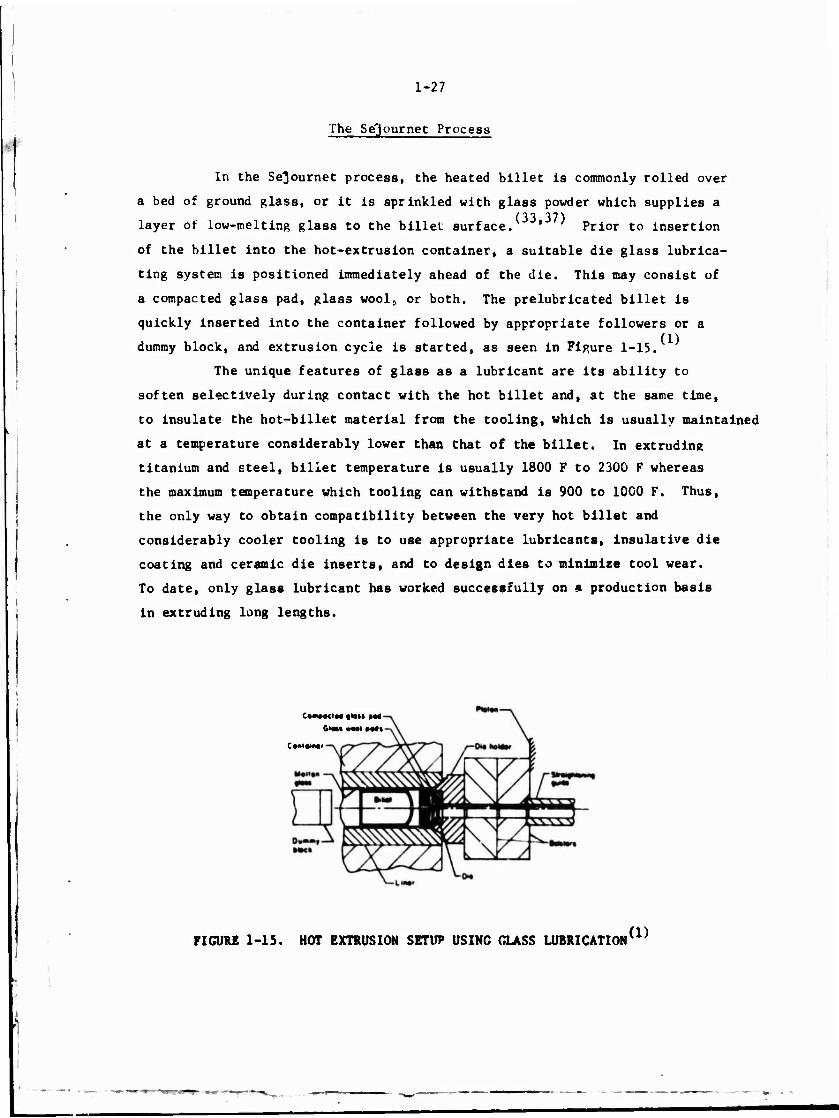
The Se'journet Process
In the Se^ournet process, the heated billet is commonly rolled over
a bed of ground glass, or it is sprinkled with glass powder which supplies a (33 37)
layer of low-melting glass to the billet surface. ' Prior to insertion
of the billet into the hot-extrusion container, a suitable die glass lubrica-
ting system is positioned immediately ahead of the die. This may consist of
a compacted glass pad, glass wool, or both. The prelubricated billet is
quickly inserted into the container followed by appropriate followers or a
dummy block, and extrusion cycle is started, as seen in Figure 1-15.
The unique features of glass as a lubricant are its ability to
soften selectively during contact with the hot billet and, at the same time,
to insulate the hot-billet material from the tooling, which is usually maintained
at a temperature considerably lower than that of the billet. In extruding
titanium and steel, billet temperature is usually 1800 F to 2300 F whereas
the maximum temperature which tooling can withstand is 900 to 1000 F. Thus,
the only way to obtain compatibility between the very hot billet and
considerably cooler tooling is to use appropriate lubricants, insulative die
coating and ceramic die inserts, and to design dies to minimise tool wear.
To date, only glass lubricant has worked successfully on a production basis
in extruding long lengths.
C»M»«IM «MM »M
GIOM »Ml »Ml
C orl«.m i
FIGURE 1-15. HOT EXTRUSION SETUP USING GLASS LUBRICATION (1)
1-28
Extrusion Speed
The actual ram speed attainable during extrusion varies with alloy
composition, extrusion temperature, and extrusion ratio, but is usually in
the range of 200 to 300 in/min. High-extrusion speeds are preferred whether
grease or glass is used as lubricant. As grease lubricants offer little
protection from the high-extrusion temperatures, the hot billet should be in
contact with the die for as short a time as possible. With glass acting as
an insulator between billet and tools, this problem is somewhat reduced.
However, the basic principle of glass lubrication, i.e., glass in a state of
incipient fusion flowing continuously from a reservoir, requires high-extru-
sion speeds. With low speeds, the glass reservoir may be depleted before
completion of the extrusion stroke, since the melting rate of the glass is a
function of time.
Die Design
Two ba.lc types of metal flow occur during extrusion of titanium
and steel with lubrication:
(1) Parallel metal flow in which the surface skin of the
billet becomes the surface skin of the extrusion
(2) Shear metal flow in which the surface skin of the
billet penetrates into the mass of the billet and
creates a stagnant zone of metal at the die shouldrr
which is retained in the container as discard. Shear
flow is undesirable because it prevents effective
lubrication of the die and can cause interior lamina-
tions and surface defects in the extruded product.
In extrusion with grease lubricants, the common practice is to use
modified flat-faced dies having a small angle and a radiused die entry. In
the ((lags-extrusion process, the die must be designed not only to produce
parallel metal flow, but also provide a reservoir of glass on the die face.
The general design employed by companies licensed for the process is a flat-
faced design with a radiused entry into the die opening. During extrusion,
the combination of the glase pad on the die and the uniform metal flow
produces a nearly conical metal flow towards the die opening.

1-29
(Ail) In a study conducted by the Republic Aviation Corporation,
extrusion trials were performed on titanium alloys C-135 Allo and MS 821 to
extrude L shapes, i.e., angles. Both glass lubricants and grease and gra-
phite lubricants were investigated. Class lubrication resulted in better
surface finish and die life. The major problem with grease and graphite
was maintaining sufficient lubrication over the full length of the extru-
sion. A multi-hole die, flat die with 20 degree inlet ani'le, seen in
Figure 1-16, produced good results. (38)
In the same study, extrusion trials were conducted at U.S.
Steel to extrude small U-shaped channels from titanium alloys. The
conclusion of this study was that conical dies had no nutlceable advantage
ovei flat-faced dies when glass lubrication was used during the extrusion.
Laminar flow was obtained with both die types. A disadvantage of conical
dies with glass lubrication was the loss of much of the glass pad with the
first foot of extrusion. When grease-based lubrication was used, shear-
type flow occurred with both conical and flat-faced die types, but the shear
cone formed was somewhat less pronounced with a conical die contour. The
flat-faced die used in this study is shown in Figure 1-16. Similar conclu- (38)
sions were made based on extrusion trials at H. M. Harder Company.
Conical dies enhanced the metal flow, but did not retain the glass for proper
lubrication. In final trials at Babcock and Wilcox Corporation, a modllled
flat-faced die was successfully employed for T-shape extrusion. The die is
shown in Fipure 1-17.
Similar die designs were used for extruding T shapes of Beta III
(39-41) and other titanius alloys with glass lubrication. In tne Sejournet
process, it is usually assumed that the primary function of tht die-glass (42)
pad is to lubricate the die. In a study conducted by Northrop and Harper
on extruding "T" sections of steel, it was determined that the glass pad
placed in front of the die does not lubricate the surface of the extrusion
and is not necessary to produce an acceptable surface finish. The function
of the die-glass pad is to provide a smooth flow pattern for the billet
material. If that is the case, then better extrusions may be obtained by
streamlined dies, even without s glass pad. The die used in Harper's study
was quite similar to that shown in Figur* 1-17. It is interesting to note
thst In the optimised die-glass pad design, the amount of glass used is very

1-30
.450
2X)0«
Ll~ ••*• Tow .tT4
«.12*
2.S7f 0,A-
SECTION A-A
SECTION B-B
FIGURE 1-16 FLAT-FACED DIE USLiD FOR EXTRUDINC g)
" TITANIUM ALLOYS T1-1S5A AND C135 AMa
I

1-31
5
0
$.7i8t>JA.
1
♦50 STRMiCtHT-
' .#"* L/i/VO SECTION Y- Y (fiQTATCti
***** Ai>e* 4 74 474A 4,77
A ,573 ■ 07* 69*
_fi_ OJ/i" 034 • 49
/.4Ä5- / 4«r /.*50
Te+o /*«* /. Ä40
.«'0
.«/O >7>
FIGURE 1-17. MODIFIED FLAT-FACED DIE DESIGN USED FOR EXTRUDING TITANIUM ALLOYS WITH GLASS LUBRICANT*38*

1-32
much reduced and the design of the shape of the glass pad is primarily for (42)
providing streamlined flow. In another study on extrusion of steel, die
design, similar tj that shown in Figure 1-17, was used.
An iiiteresting conclusion was made in a study on the extrusion of (A4)
Beryllium. In this study, it was determined that flat-faced dies are
best for the glass lubricant approach, i.e., Se^ournet process, but dias with
conical entry are best suited for using composite lubricants having metallic
and non-glass liquid components. Based on several extrusion trials, a conical
entry die was selected to encourage smooth metal flow. The dies were cast by
the Shaw process by "Duplicast Die Company of Detroit" and were finished at
the "Moczik Tool and Die Company, Detroit". Of special importance to our
project is their conclusion quoted here. "It was apparent from past experience
that the die design would have to be altered radically because of the complete
change in type and method of application of lubricants. Under the Sejournet
.■system of glass lubrication, flat-faced design was a necessity to provide the
reservoir of semi-molten glass which was gradually drawn off as the billet
passed the so-called "dead zone". With the composite lubricant technique in
which the beryllium never touches the die, the metallic and liquid lubricants
are applied over the entire billet surface prior to insertion into the container.
This obviates the need of the reservoir provided by flat-faced dies and, in
fact, dictates the need for smoother, more streamlined flow". This was accom-
plished best by using a conical die approach. In the study with glass lubrica-
tion, conical contour dies with varying geometries were tried. With dual
lubricant systems, a curved die, as shown in Figure 1-18, was used.
The above conclusion does not seem to apply to all situations. In
extruding complex thin H-sections of Tantalum alloy,' ^' better and more
consistent results were obtained with the conical li-dies than the modified
flat dies. Conical dies have also been used in glass-lubricated extrusion of
T shapes from TZM alloy, ' as shown in Fij»ur» 1-19.
The review of past studies show that, basically, two types of dies
are used for extruJing steel and titanium: (a) flat-faced die, or modified
flat-faced die with radiused entry, and (b) conical entry die. It seems that
flat-faced dies, or modified flat-face dies are used with glass lubrication
with glass pad forming the die contour at the entrance. The conical entry

1-33
1/8R
6C1
Approx. 9° Relief in Corners
±.002 .002
002
; *. 0021 ,, n I—- 1.496 Ij -110
Die Opening Details
5° Typical Except in Corners
SfCT/CN^-J^ SEcn «NJB-B
FIGURE 1-18. CURVED DIE USED FOR EXTRUDING &ERYLLIUM (44)

1-34
Ct z öS Uü
LU m
Ul
to 2 _J Q 3
IK LI
2 I
I oo UIL;99
o^ p
2P><
c\J
o
i 3 !
a * i
h I«
0901
o in
OZC
—
8 o
> UJ o 2 <r 5
\
_ .i 1 o z o o
-ig« a in
U U
i
CO w
X
H Ü Z H Q
I W
Pi O
Q to
w M o
< M z o u
1.-35
die is mostly used with grease lubrication, although there is evidence, at
least in extrusion of other high-strength alloys, that conical-contoured
dies are also used with glass lubrication. From the review, it is obvious
that in designing dies for lubricated extrusion, an important consideration,
in addition to uniform flow, is the uniform distribution of lubricant on the
surface of the billet.
DESIGN OF STREAMLINED DIES IN SHAPE EXTRUSION
From the present review, it is quite apparent that die design in 9
shape extrusion is quite complex and it is influenced by a variety of factors,
such as the type of extrusion process, (direct, indirect, or hydrostatic), the
material to be extruded, (aluminum, steel, or titanium), extrusion temperature
and pressure, lubrication (unlubricated, glass lubrication, or grease lubrica-
tion), and the desired shape of the product. Other factors that will influence
die design are billet size, press capacity, extrusion ratio, number of cavities
in die, press-tool arrangement, and die materials.
No single die design can be used for all possible extrusion condi-
tions. Thus, it may be advisable to suggest alternative die designs for the
following types of extrusions:
(1) Materials hot extruded in a direct process with
glass lubrication, glass pad being used between
the billet and the die. This group includes the
extrusion of steels, titanium alloys, and high-
temperature alloys.
(2) Materials hot extruded in a direct process with
grease or oil type lubricants, including hard
aluminum alloys.
(3) Materials that can be more economically extruded
through shear-faced dies without lubrication.
Soft aluminum alloys would fall in this category
where calculation of extrusion pressure and
design of die land to give uniform flow are two
areas requiring engineering improvements.
1-36
(4) Materials extruded by hydrostatic extrusion process.
(5) Shapes too complex to be extruded by a single con-
toured die. This group may include aluminum alloys
that are usually extruded to complex shapes through
bridge or porthole dies.
The possible die designs feasible with the streamlined die design
approach are shown in Figure 1 20, along with the applications for which these
may be suitable. It is advisable to omit group (5) above altogether, and also
not to propose lubricated extrusion cf soft aluminum alloys since this may not
be economically feasible.
In all the die designs of Fipure 1-20, except in the flat-faced die,
Figure l-20d, the die surface provides a smooth transition from the billet
shape to the required final shape. The final shape of the transition zone can
be the product shape, or some other defined shape surrounding the die opening,
as seen for the curved-flat die in Figure l-20b. In all cases, the die surface
must be defined and optimized taking into account the variables of the extru-
sion process.
All the shapes like L, T, U, and H, used for military applications,
can be represented by assembling rectangles of different sizes having different
amount of offset from the billet axis. This suggests that a basic rectangle,
positioned off-center from the billet axis, can serve as a module for the
purpose of defining the streamlined die surface and for analyzing metal flow.
SUMMARY
This chapter presents a survey of the present stat» of the art in
die design, as related to extrusion of shapes from aluminum alloys, steels,
and titanium alloys. The purpose of this survey was to
(1) Characterize the extruded structurals used
for military aircraft applications.
(2) Assess and gather the existing literature relevant
to die design in extrusion of structural shapes.
(3) Define guidelines for subsequent tasks on the
current project for CAD/CAM of extrusion dies.

1-37
(a) Streamlined die
(2)
(b) Curved-flat die
(i) (4)
This portion of die may be replaced by glass pad
(c) Conical-curved die
(2)
(d) Flat-faced die with variable land
(3)
FIGURE 1-20. POSSIBLE DIE DESIGNS FOR EXTRUSION OF ALUMINUM, STEEL AND TITANIUM ALLOYS
(The Numbers Below Each Sketch Indicates the Possible Application as Described in Text)

1-38
The present chapter deals with the extrusion of aluminum allovs separately from
the extrusion of steels and titanium alloys, because of the different tech-
nologies associated with extrusion of these materials. The review shows
that in extrusion of aluminum alloys, flat-faced dies are used which limit
the extrusion rate for the hard aluminum alloys, 2000 and 7000 series. The
past work on lubricated extrusion of hard aluminum alloys suggests that it is
possible to increase the extrusion rates by using the lubricated extrusion
process with streamlined dies. The design of streamlined dies, and die and
billet lubrication are two areas which need further investigation.
The extrusion of steels and titanium alloys is either done by the
conventional direct extrusion process with grease-graphite lubricants, or
more commonly by the Sejournet process with glass lubrication. In either
case, the high strengths of these materials require that a smooth transition
is provided in the die from the billet to the final shape. With glass
lubrication, the glass pad, together with the flat-faced die, provides that
transition. With grease-graphite lubricants, the d*z must provide a smooth
change of shape and, therefore, in this case, die design becomes relatively
more important than in extruding with glass.
There are many variables in the extrusion process. Therefore, one
particular die design is not likely to be suitable for all situations. The
structural shapes used in aircraft applications are relatively simple and
can be considered as formed by assembling several rectangles in appropriate
manner. Therefore, a rectangular module can serve as a basis for die design
in lubricated streamlined extrusion.

1-39
REFERENCES
(1) Byrer, T. G., et al., ,;Design Guide for Use of Structural Shapes in Aircraft Applications", Battelle's Columbus Laboratories, Columbus, Ohio, Technical Report AFML-TR-73-211, September, 1973.
(2) Gerds, A. F., et al., "Deformation Processing of Titanium and Its Alloys", Battelle Memorial Institute, Columbus, Ohio, NASA Technical Memorandum NASA TM X-53438, April, 1966.
(3) "Aluminum Extrusions, Fabricating and Anodizing", Booklet by Southern Extrusions, Inc., Magnolia, Arkansas.
(4) Akeret, R., and Stratman, Paul M., "Unconventional Extrusion Processes for the Harder Aluminum Alloys", Part I and II, Light Metal Age, April, 1973, pp 6-10, and June, 1973, pp 15-18.
(5) Chadwick, R., "Developments and Problems in Package Extrusion Press Design", Metals and Materials, May, 1969, pp 162-170.
(6) Akeret, R., "A Numerical Analysis of Temperature Distribution in Extrusion", J. Inst. Metals, 95, 1967, p 204.
(7) Lahoti, G. D., and Altan, T., "Prediction of Metel Flow and Temperatures in Axisymmetric Deformation Processes", presented at the 21st Sagamore Army Materials Research Conference, August 13-16, 1974, published in the Proceedings.
(8) Lahoti, G. D., and Altan, T., "Prediction of Temperature Distributions in Tube Extrusion Usin<» a Velocity Field Without Discontinuities", Proceedings of the 2nd North American Metalworking Research Conference, Madison, Wisconsin, May, 1974, pp 209-224.
(9) T. Munker, German Patent No. 901,529, 1953.
(10) Laue, K., "Isothermal Extrusion", (in German), Z. Metallkunde, 51, 1960, p 491.
(11) Fernback, H. R., "Programmed Speed-Control Methods for Extrusion Process", J. Inst. Metals, 92, 1963-64, pp 145-U8.
(12) ..aturin, A. I., "Extrusion of Aluminum Alloys Through a Water-Cool. J Die", (in Russian), Kuznechno-Shtampovochnoye Proizvodstvo, No. 8, 1966, pp 5-9.
(13) Aluminum, Vol. 3, Fabrication and Finishing, edited by K. R. Van Horn, American Society for Metals, Metals Park, Ohio, 1967, pp 81-132.
(14) Carl DeBuigne, "Design and Manufacture of Aluminum Extrusion Dies", Light Metal Age, 2]_, April, 1969, pp 28-33.
(15) Bello, Luis, Aluminum Extrusion Die Correction, First edition, Fellom
Publications, San Francisco.
1-40
(16) Mockli, F., and Locher, M., "State of the Art in Making Extrusion Dies", Aluminum, (in German), 41, 1965, p 629.
(17) Keegan, J. W., "Hints in Modern Cold Heading", Automatic Machining, 2j*, No. 2, 1966, pp 63-66.
(18) Wilson, G., "Cold Forging", Metal Treatment, 33, No. 252, 1966, pp 345-353.
(19) Feldmann, H. D., "Cold Forging of Steel", Hutchison and Companv, Ltd., 1961.
(20) Sieber, K., "Special Cold Forging Tools, Particularly for Solid Forming on Multi-Stage Transfer Presses", Wire World International, 6^, No. 6, 1964, pp 165-178.
(21) Chadwick, R., "The Hot Extrusion of Nonferrous Metal«", Metallurgical Reviews, 1959, 4, No. 15, pp 189-255.
(22) Perlin, I. L., Theory of Metal Extrusion, published by "Metallurgiya", Moscow, 1964 (English Translation FTD-HT-23-616-67).
(23) Scrutton, R. F., Robbins, B., and The, J. H. L., "The Exit Lands in Extrusion Die Design", (unpublished research).
(24) Heinen, B., "Manufacturing and Correction of Extrusion Dies", (in German), Z. Metallkunde, 58, 1967, p 215.
(25) Shape Design Manual- Aluminum Extrusions, Aluminum Limited, October, 1964, AIA-RAIC FILE NO. 15-L, ALCAN Aluminum Corporation, 111 West Fiftieth Street, New York, N. Y. 1U020.
(26) Akeret, R., "Research in the Nonferrous Metal Product Industry, Pan XX, Effects of Lubricating the Container on the Extrusion of Aluminum and Aluminum Alloys", (in German), Z. Metallkunde, 55, 10 (1964), pp 570-*>7}.
(27) Nichols, D. E., Byrer, T. G., and Sabroff, A. M., "Lubricated Extrusion of 2024 Aluminum Alloy Using Conical and Conical-Flat Dies", Summary Report to Batt«lle Development Corporation, Battelle's Columbus Laboratories, Columbus, Ohio, January 23, 1970.
(28) Kornilov, V. V., Nedourov, Yu. S., Antcnov, E. A., Abrosimov, A. I., and Smirnov, G. A., "Experimental Extrusion of Aluminum-Alloy Fan Blades", (in Russian), Kuznechno-Shtampovochnoye Proizvodstvo, 1J), October, 1970, p 15.
(29) lvonov, I. I., Rakhmanov, N. S., Molodchinin, E. V., Molodchinina, S. P., and Medvedava, R. D., "Extrusion of Thin-Walled D 16 Alloy Tubes on a Vertical Press", The Soviet Journal of Nonferrous Metals, % (7), July, 1968, p 100.
(30) Schey, J. A., Wallace, P. W., and Kulkarni, K. M., "Thick-Film Lubrica- tion in Hot Extrusion", U.S. Air Force Materials Laboratory, Technical Report AFML-TR-68-141, M#y, 1968.

1-41
(31) Wallace, P. W., Kulkarni, K. M., and Schey, J. A., "Thick-film Lubrica- tion in Model Extrusions with Low Extrusion Ratios", Journal of the Institute of Metals, 100, 1972, p 78.
(32) Hornmark, N., Nilsson, J. 0. H., Mills, C. p., "Quintus Hydrostatic Extrusion", Metal Forming, 37^, August, 1970, p 227.
(33) Sejournet, J., and Delcroix, J., "Glass Lubricant in the Extrusion of Steel", Lubrication Engineering, 11, 1955, p 389.
(34) Turner, F. S., "Manufacturing Technology for Materials, Designs and Fabrication of Extrusion Dies for Hot Extruding of Steels and Titanium Structural Sections", Allegheny Ludlum Industries, Inc., Brackenridge, Pennsylvania, Technical Report AFML-TR-73-61, 1973.
(35) Turner, F. S., "Die Materials for Hot Extruding Steel and Refractory Metals", Allegheny Ludlum Steel Corporation, Technical Report AFML-TR- 68-316, October, 1968.
(36) Haverstraw, R. C, "High Temperature Extrusion Lubricants", TRW Electro- Mechanical Division of TRW, Inc., Cleveland, Ohio, Final Report, Contract No. AF 33(657)-9141, Report ML-TDR-64-256, July, 1964.
(37) Haffner, E. K. L., and Sfijournet, J., "The Extrusion of Steel:', Journal of the Iron and Steel Institute, June, 1960, p 145.
(38) Christiana, J. J., "Improved Methods for the Production of Titanium Alloy Extrusions", Republic Aviation Corporation, Contract AF 33(600) 34098, ASD Project: 7-556, Final Technical Engineering Report, December, 1963.
(39) Loewenstein, ?., and Gorecki, T. A., "Production Techniques for Extruding and Drawing Beta III Titanium Alloy Shapes", Whittaker Corporation/Nuclear Metais Division, Technical Report AFML-TR-72-97, May, 1972.
(40) Corecki, T. A., et al., "Production Techniques for Extruding, Drawing, and Heat Treatment of Titanium Alloys", Fairchild Hiller, Republic Aviation Division, Technical Report AFML-TR-68-3<49, December, 1968.
(41) Kosinski, E. J., and Loewenstein, P., "Manufacturing Methods of an Isothermal Extrusion Process to Produce 20 Foot Complex Sections", Whittaker Corporation, Concord, Massachusetts, Contract F 33(615)-70- C-1545, Interim Engineering Report No. 1, August, 1970.
(42) Scow, A. L., and Dempsey, P. E., "Production Processes for Extruding, Drawing, and Heat Treating Thin Steel Tee Sections", Technical Report AFML-TR-68-293, October, 1968.
(43) Chrlstensen, L. M., "The Development of Improved Methods, Processes, and Techniques for Producing Steel Extrusions", Northrop Corporation, Technical Documentary Report No. ML-TDR-64-231, July, 1964.
1-42
(44) Christensen, L. M., and Wells, R. R., "Program for the Development of Extruded Beryllium Shapes", Northrop Corporation, Contract AF 33(600)- 36931, ASD Technical Report 62-7-644, June, 1962.
(45) Krom, R. R., "Extruding and Drawing Tantalum Alloys to Complex Thin H-Sections", Nuclear Metals, Division of Textron, Inc., Technical Report AFML-TR-66-119.
(46) Santoli, P. A., "Molybdenum Alloy Extrusion Development Program", Allegheny Ludlum Steel Corporation, Technical Documentary Report No. ASD-TDR-63-593, May, 1963.

CHAPTER IT
"COMPUTER-AIDED DESIGN AND MANUFACTURING (CAD/CAM) OF A STREAMLINED DIE FOR A MODULAR SHAPE"
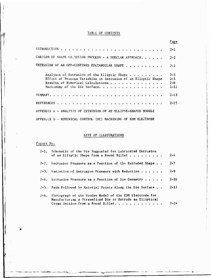
TABLE OF CONTENTS
Page
INTRODUCTION 2-1
CAD/CAM OF SHAPE F.X.'iUSION PROCESS - A MODULAR APPROACH 2-2
EXTRUSION OF AN OFF-CENTERED RECTANGULAR SHAPE 2-3
Analysis of Extrusion of the Elliptic Shape 2-3 Effect of Process Variables in Extrusion of an Elliptic Shape 2-5 Results of Numerical Calculations 2-6 Machining of the Die Surface 2-11
SUMMARY 2-13
REFERENCES , . 2-15
APPENDIX A - ANALYSIS OF EXTRUSION OF AN ELLIPSE-SHAPED MODULE
APPENLIX B - NUMERICAL CONTROL (NC) MACHINING OF EDM ELECTRODE
LIST OF ILLUSTRATIONS
Figure No.
2-1. Schematic of the Die Suggested for Lubricated Extrusion of an Elliptic Shape from u Round Billet 2-4
2-2. Extrusion Pressure as a Function of the Extruded Shape . . 2-7
2-3. Variation of Extrusion Pressure with Reduction 2-9
2-4. Extrusion Pressure as a Function of Die Geometry 2-10
2-5. Path Followed by Material Points Along the Die Surface . . 2-12
2-6. Photograph of the Wooden Model of the EDM Electrode for Manufacturing a Streamlined Die to Extrude an Elliptical Cross Section from a Round Billet 2-14

CHAPTER II
CAD/CAM OF A STREAMLINED DIE FOR A MODULAR SHAPE
ABSTRACT
This chapter describes the work conducted towards applying CAD/CAM
techniques to tho extrusion of a modular shape, which was selected to be an
ellipse approximating a rectangle. A theoretical analysis is presented for
predicting the metal flow, the extrusion pressure, and the effect of various
process variables in extrusion of the selected modular shape. Based on the
analysis, computer pre rams are developed to simulate the extrusion process.
The analysis and the computer programs were used to analyze the cold extru-
sion of the modular shape from Al 1100. The results indicate that the
predicted values agree qualitatively with the available data.
For some selecced extrusion conditions, optimal die shapes were
obtained using minimum extrusion pressure as the criterion. To manufacture
the dies by Electrical-Discharge Machining (EDM) process, computer programs
were developed for numerical control (NC) machining of the EDM electrode.
INTRODUCTION
In today's industrial practice, a variety of shapes from aluminum
alloys are extruded without lubricants by using flat-faced dies. This prac-
tice, particularly with the high-strength alloys, i.e., 2000 and 7000 series,
results (a) in significant redundant work associated with Internal shearing, (1 2)
and (b) In temperature Increases within the deformation zone. ' Consequently,
the extrusion process requires large press loads and It must be carried out
very slowly to avoid incipient melting in the extruded product.
2-2
VJith lubricated extrusion of aluminum alloys, it should be possible
to reduce the redundant work and internal shearing in the deforming material.
Thus, extrusion pressures and temperature increases are kept at a moderate
level and, consequently, higher extrusion speeds can be achieved without
causing hot shortness of the product. The use of lubricants in extruding
aluminum alloys requires a new approach in die design. As long as the cross
section of the extruded product is circular, optimum die configurations can
be obtained by using one of the existing analyses. However, for extruding
more complex shapes, such as U, L, T, I and others, it is necessary to pro-
vide a smooth transition from the circular container, or billet, to the shaped
die exit. The effective design of such a die must ensure a smooth metal flow
and consistent lubrication. At this time, there are no known methods to
analyze the metal flow and to optimize die configuration for lubricated extru-
sion of nonsymrnetric shapes.
Extrusion dies with smooth entries, from a circular cross section
into an extruded shape, are also used in extrusion of steels, superalloys, and
titanium alloys. A significant application is found in extrusion of preforms (3)
for forging titanium turbine and compressor blades. Before forging the thin
airfoil section, a round, or preferably an elliptical shaped preform is extruded
from round bar stock. The shape of the preform and the surface of transition
from the round to the elliptical cross section influence the subsequent forging
of the blade without any defects.
The present program is primarily aimed at increasing the productivity
in extrusion of high-strength aluminum alloy structural shapes, especially
those from 2000 and 7000 series. However, the CAD/CAM techniques being developed
in this program, with appropriate minor modifications, will be applicable to
extrusion of shapes from other aluminum alloys, titanium alloys, steels, and
superalloys.
CAP/CAM OF SHAPE EXTRUSION PROCESS - A MODULAR APPROACH
Extrusion of shapes is an extremely complex deformation process from
the point of view of deformation mechanics. The metal flow, the friction at
the tool-material interface, and the behavior and properties of the deforming
material (under the temperature, strain rate, and strain conditions of the
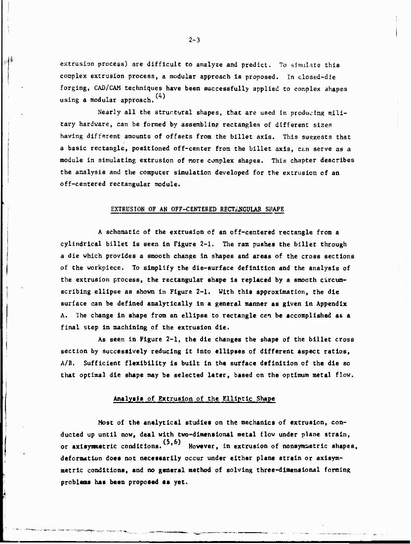
2-3
extrusion process) are difficult to analyze and predict. To simulate this
complex extrusion process, a modular approach is proposed. In closed-die
forging, CAD/CAM techniques have been successfully applied to complex shapes (4)
using a modular approach.
Nearly all the structural shapes, that are used in producing mili-
tary hardware, can be formed by assembling rectangles of different sizes
having different amounts of offsets from the billet axis. This suggests that
a basic rectangle, positioned off-center from the billet axis, can serve as a
module in simulating extrusion of more complex shapes. This chapter describes
the analysis and the computer simulation developed for the extrusion of an
off-centered rectangular module.
EXTRUSION OF AN OFF-CENTERED RECTANGULAR SFAPE
A schematic of the extrusion of an off-centered rectangle from a
cylindrical billet is seen in Figure 2-1. The ram pushes the billet through
a die which provides a smooth change in shapes and areas of the cross sections
of the workpiece. To simplify the die-surface definition and the analysis of
the extrusion process, the rectangular shape is replaced by a smooth circum-
scribing ellipse as shown in Figure 2-1. With this approximation, the die
surface can be defined analytically in a general manner as given in Appendix
A. The change in shape from an ellipse to rectangle cen be accomplished as a
final step in machining of the extrusion die.
As seen in Figure 2-1, the die changes the shape of the billet cross
section by successively reducing it Into ellipses of different aspect ratios,
A/B. Sufficient flexibility Is built in the surface definition of the die so
that optimal die shape may be selected later, based on the optimum metal flow.
Analysis of Extrusion of the Elliptic Shape
Most of the analytical studies on the mechanics of extrusion, con-
ducted up until now, deal with two-dimensional metal flow under plane strain,
or axisyrametric conditions. ' However, in extrusion of nonsymsetric shapes,
deformation does not necessarily occur under either plane strain or axisym-
metrlc conditions, and no general method of solving three-dimensional forming
problems has been proposed as yet.

•H I u~ U /T> a. •H -h
* IT) 1
H w
r-i V i in J W 4-1 >>^ -v* r ►-I
a to cu X w X u H O 4-1
<u -.* c < 2 ^J ft)
U-i ■H s* > 0 M O 0 Q A \ ^ ■H
CO PS OS
c 4J -4- + 1 3 1 G ■< o m ^ V J. ji- t 4-1
_i V 2
4J 01 V • 1 X OS c ■H O. 1 w O 06 03 <TJ u, ft. c X St ft, in G Q ft!
,1* •H U ft. l< H 25 *-*N a
XI Q u I/.
ro 4-1 0 0 u
i— H—r~ 01 D M
f —i <Sj H
>%■* v ]7~ •rt ft. W 1-1
V x cc M _] Q J
CU U £ ft) U 53
1 x 1+4
0 ft. ft. 0 0
1 Ul s~ +X c U 15 / , x c M O tn f \ •* H M
•H / i \ CJ 4-1 < tn 3 •
4=1 CO 0
-X M 1 ft) x X H
t-> IK
X. |
I"/ o a V , y T, cr. u; c m x^ 1/ 10 •H X T £ (^
u iH J= u 1 (K. ~« rj 3 «-< X .*■*.
O O. 1 u ft] U -H ■—' 0: j= ^ ft» H <-t / \ •O
W / \ M C I \ ft, O 01 I \ —
■H .c 1 « 1 1 ■ u u \ 1 - u \ I 01 >M \ 1 to o \ /
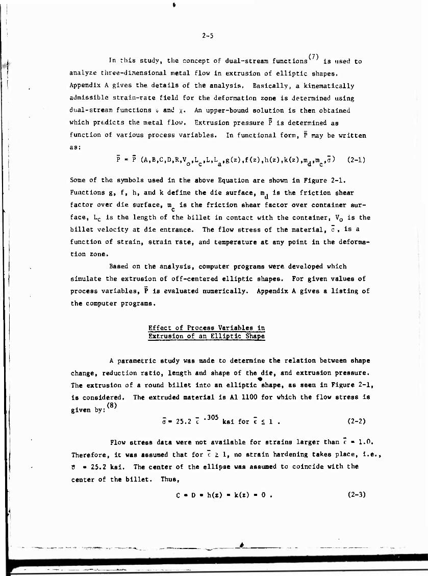
2-5
In this study, the concept of dual-stream functions is used to
analyze three-dimensional metal flow in extrusion of elliptic shapes.
Appendix A gives the details of the analysis. Basically, a kinematically
admissible strain-rate field for the deformation zone is determined using
dual-stream functions v and x« An upper-bound solution is then obtained
which predicts the metal flow. Extrusion pressure P is determined as
function of various process variables. In functional form, P may be written
as:
P - P (A,B,C,D,R,V L ,L,L g(z),f(z),h(z),k(z),m.,in ,0) (2-1) oca a c
Some of the symbols used in the above Equation are shown in Figure 2-1.
Functions g, f, h, and k define the die surface, m, is the friction shear
factor over die surface, m is the friction shear factor over container sur- c
face, Lc is the length of the billet in contact with the container, V0 is the
billet velocity at die entrance. The flow stress of the material, o , is a
function of strain, strain rate, and temperature at any point in the deforma-
tion zone.
Based on the analysis, computer programs were developed which
simulate the extrusion of off-centered elliptic shapes. For given values of
process variables, P is evaluated numerically. Appendix A gives a listing of
the computer programs.
Effect of Process Variables in Extrusion of an Elliptic Shape
A parametric study was made to determine the relation between shape
change, reduction ratio, length and shape of the die, and extrusion pressure.
The extrusion of a round billet into an elliptic shape, as seen in Figure 2-1,
Is consid<
given by:
Is considered. The extruded material is Al 1100 for which the flow stress is (8)
105 a- 25.2 t ,JUJ ksi for e < 1 (2-2)
Flow stress data were not available for strains larger than t ■ 1.0.
Therefore, it was assumed that for e > 1, no strain hardening takes place, i.e.,
ü - 25.2 ksi. The center of the ellipse was assumed to coincide with the
center of the billet. Thus,
C - D - h(z) - k(z) - 0 . (2-3)

2-6
Also, the container surface was assumed to be trictionless, i.e., m = 0. c
The functions g(z) and f(z) define the die surface. A general
polynomial form for these functions was selected as follows:
g(z) R + C L2 3(R-A) \ 2 5— I z +
2(R-A) 2C1L
3 4 z + C.z (2-4a)
f(z) - R + |C3L2 3(R-B) 12/ 2(R-B) . „ T 1 3 , „ 4 ,„ ...
2 z + ( 3 * 2 CjL z + C3z . (2-4b)
C. and C- are some arbitrary constants of the polynomial, describing the die
surface. This polynomial form was chosen because it can approximate, very
closely, the shape of ideal dies for frictionless rod extrusion. Also, recent (9)
studies at Battelle on the possibility of using curved dies for shell draw-
ing have indicated that this form yields high-forming efficiency.
A measure of complexity of the extruded elliptic shape is the ratio
of the major axis to the minor axis, A/B. When this ratio is equal to 1, the
extruded product has a circular cross section. For A/B t 1, extrusion with
elliptic cross section is obtained. As the ratio A/B is progressively increased,
the shape deviates more and more from a circle. A more general representation
of the extruded shape complexity is the so-called "shape factor", S, defined
as:
Perimeter in Inches Shape Factor, S -
Weight in Pounds per Foot .
The shape factor, S, is a measure of the amount of surface that is
generated per pound of metal extruded. This factor affects the production rate,
and the cost of manufacture and maintenance of the dies. It is used by many
extruders in Aluminum industry as a basis for pricing and gives the designer
a means of comparing the relative complexity of alternate designs.
Results of Numerical Calculations
Figure 2-2 shows the variation of extrusion pressure with the
parameter A/B and with the shape factor, S, for a given set of process
parameters (m , C , C~) and reduction. As seen in this curve, the extrusion
pressure increases rather slowly with the shape factor. The percentage increase
in pressure, I, with increasing value of the shape factor is also t^iven in
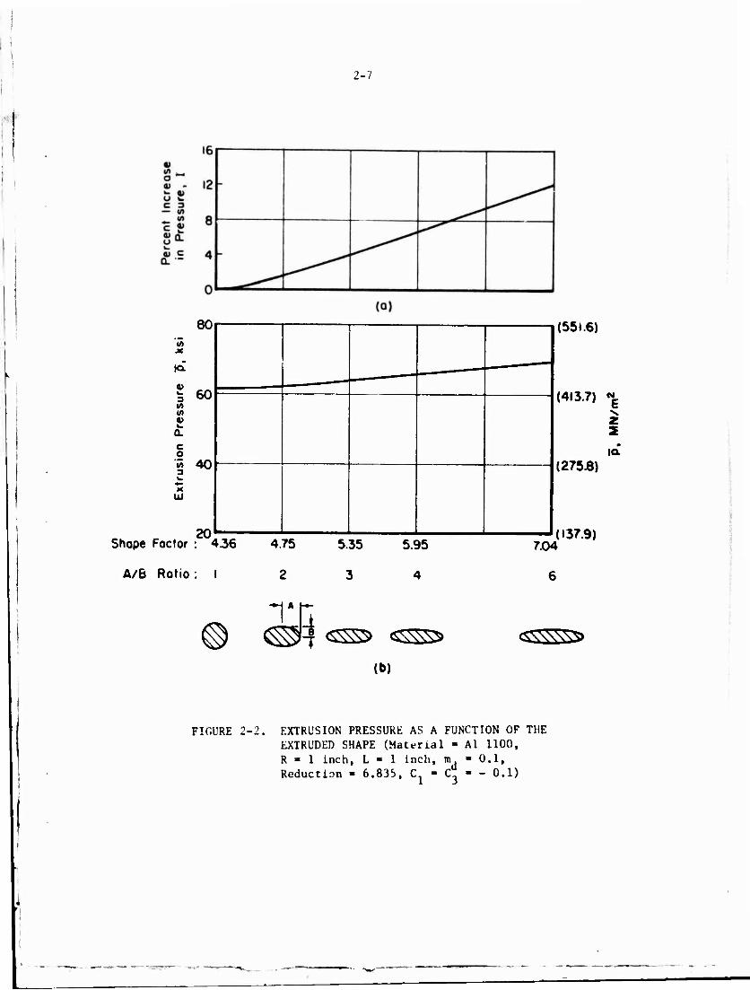
2-7
in
la
3
m 4)
80
60
o 55 40
UJ
20 Shape Foctor : 436
A/B Ratio: I
(551.6)
(413.7) «|
z 2
ta (275.8)
4.75
2
1*
5.35
3
5.95
4
7.04
6
(137.9)
(b)
<SSX\\\S>
FIGURE 2-2. EXTRUSION PRESSURE AS A FUNCTION OF THE EXTRUDED SHAPE (Material - Al 1100, R » 1 inch, L ■ 1 inch, m Reduction - 6.835, C 1
0.1, - 0.1)

2-8
Figure 2-2. An increase in pressure of only 12 percent Is obtained when shape
factor increases from 4.36 to 7.04. This slow rate of increase in mean pres-
sure with shape change is not surprising. A similar observation has been made
by Kast in experimental investigation of the backward extrusion process by
using punches with different shapes. Qualitatively, it is not difficult to
explain this observation. The pressure variation increases with increasing i
shape factor, S, locally within the die cross section. However, the mean
pressure is not influenced appreciably, provided the total reduction in area
is kept constant.
Figure 2-3 shows the pressure variation with reduction in area for a
given die, when the ratio A/B is kept equal to 2. As expected, the pressure
increases with reduction in area. The extrusion pressure versus reduction in
area for rod extrusion, A/B =1, is also shown in Figure 2-3. The two curves
follow each other very closely. The percentage increase in mean pressure due
to shape change, I, decreases steeply with increasing reduction.
The determination of the optimum die profile is very important in
lubricated extrusion. The criterion used to select the optimum die profile
depends upon the end use of the extruded product. For rod extrusion, it is
usually assumed that a die shape, which requires minimum rate of energy con-
sumption, or pressure, also yields the minimum average strain in the extruded
product. Thus, the optimum die shape is considered to be the shape which
results in minimum extrusion pressure. The same criterion is used here for
shape extrusion. It should be stated at this time that, due to the approxi-
mate nature of the upper-bound solution, the die profile obtained by minimizing
the pressure will only approximate the optimum die configuration. Figure 2-4
shows the dependence of pressure upon the die shape parameters, namely, L, and
C . For a given reduction, an optimum die length, L, and die profile coeffi-
cients, C and C_, can be determined such that the extrusion pressure is
minimum. However, the variation of pressure near the optimum values of L, C.,
and C- is rather small. The saving in rate of energy consumption, by obtaining
an optimum die, is not significant to justify the determination of the optimum
die profile with great accuracy.
It is interesting to note that for the same reduction, the value of
the optimum die length, L ■ 1.88, obtaiutd for elliptic extrusion, is very
close to the optimum length, L ■ 2.0, obtained for rod extrusion through a t\ *)\ opt
cosine-shape die. Since the extrusion pressure varies only slightly near

2-9
10"
a> o 4) " Z 0)
C 3
— (A «A c *- a) 0
C w 4) Q. O fc5 0 £
(a)
140
120
._ 100 «A JC
m
la
w 3 80 (A (A 0) v. Q.
c 60 o «A 3 w ^» X
UJ 40
20 -
A/B«2 -v
-
/
— A/B«l -
- -
8
(965.3)
(827.4)
-(6895)
N
(551.6) £
(413.7)
(275J8)
FIGURE 2-3.
16 24 Reduction (A0/Af)
(b)
VARIATION OF EXTRUSION PRESSURE WITH REDUCTION
- (137.9)
p*
(Material - Al 1100, n, L • 0.65 Inch, Cj - Cj
0.1, R - 0.1)
1.0 inch.

2-10
« 60-
w 3 •>
59 *■ 3 K V» WS 58
CL
57
- -
- ^y
- 1 1 1 •
«» 62 M.
m
KX 61
• w 3 •»
• 60 w
Q.
c o 59 •» 3 t.
58 UJ
57
.15 .05 -.05 -.1 -.15
Coefficient, C, (o)
t-opt
- (413.7) CM
tz (406.8)
(399.9) ,a
(393.0)
■ i '
- (427.5)
(420.6) CM
(413.7) v 2
(406.8) •*
H (399.9)
(393.0) .8 1.0 12 1.4 1.6 1.8 2.0 2.2 2.4 2.6 (in.) ■ ■ * i ■ i ■ * i I
20.3 25.4 30.5 35.6 406 45.7 50.8 55.9 61.0 66X) (mm)
Length, L
(b)
FIGURE 2-4. EXTRUSION PRESSURE AS A FUNCTION OF Uli Cl.ovi IKY
(a) Pressure Versus Die Profile CoeffliItni, C (I. - 1.88 Inch, C - Ü)
(b) Pressure Versus Die Length, L (C. i - »■)
(Material ■ Al 1100, m - 0.1, K - I lml., Reduction - 6.835, A - 0.5i inch, K ■• U..T inch)
2-11
the optimum length, this suggests the possibility of selecting die length in
shape extrusion by analyzing rod extrusion.
In a steady-state process, the streamlines also represent the paths
followed by the material particles during deformation. In the present analysis,
the metal flow along the die surface was determined from the velocity field.
Paths followed by material points on the die surface are shown in Figure 2-5. (13)
Comparison of material path lines with experimental data shows excellent
agreement. As it is seen in Figure 2-5, the metal flow is not radial.
The following conclusions can be drawn from these numerical calcula-
tions:
(1) The mean pressure, necessary to extrude Al 1100 from a
round stock to an elliptic shape, depends largely upon
the reduction in area. The configuration of the ex-
truded shape does not affect the extrusion pressure
considerably, especially at high reductions.
(2) The use of dual stream functions, with appropriate
numerical techniques, allows determination of an
optimum smooth die configuration for lubricated
extrusion from round to an elliptic shape. In this
case, "optimum" is defined as the die shape which
requires the minimum pressure for given material,
friction factor, and extrusion ratio.
(3) Slight variations in the optimum die shape do not
influence the extrusion pressure significantly.
(4) In extruding elliptic shapes, the velocity field,
obtained by using dual stream functions, does not
give a radial metal flow.
Machining of the Pie Surface
The die used for extruding elliptic-shaped modules has a complex
three-dimensional surface. This «urface cannot be easily machined by con-
ventional methods like copy-turning or milling. Electrical-discharge
machining (EDM) is one of the methods that can be used to manufacture such
dies. In this process, the appropriate surface geometry is machined on an
EDM electrode. This electrode is then used to EDM the rough-machined die
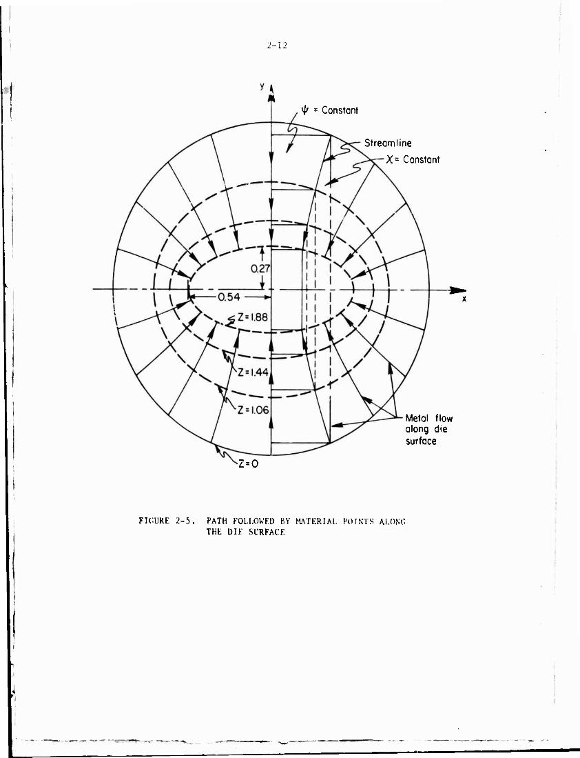
2-12
ty = Constant
Streamline
X= Constant
Metal flow along die surface
*Z = 0
FICUKE 2-5. PATH FOLLOWED BY MATERIAL POINTS ALONG THE DIF SURFACE
2-13
block to generate the desired surface.
Standard APT (Automatically Programmed Tools) systems cannot be
readily used to machine the EDM electrode needed for dies in our case.
Therefore, special-purpose FORTRAN programs were developed for NC machining
of the electrode. Appendix B gives the details of the mathematical deriva-
tions used in developing these computer programs. A wooden model of the
EDM electrode was machined on an NC machine at Battelle, and it is seen in
Figure 2-6. Visual and dimensional inspection of the machined surface
indicated that the proper surface was generated.
SUMMARY
This chapter describes the worK conducted toward applying
CAD/CAM techniques to a modular shape in shape-extrusion process. Most of
the extruded shapes that find application in military hardware have relatively
simple shapes like T, U, L, and Z. For thee« shapes, a rectangular module can
be used as a building block for simulating the extrusion process.
In this study, the rectangular nodule has been approximated
by an ellipse and the upper-bound method has been applied to analyse the
mechanics of the process for extruding the modular shape. The analysis pre-
dicts the characteristics of metal flow, extrusion pressure, rate of energy
required, and the effects of various process variables, such as reduction
ratio, length of the die and material properties. Based on the analysis,
computer programs were written to simulate the extrusion process.
The computer programs were used to analyse cold extrusion of Al 1100.
A parametric study was made to determine the relation between shape change,
reduction ratior length and shape of the die, and the extrusion pressure.
Comparison with existing data Indicates that the proposed analysis and the
computer programs adequately simulate the extrusion process.
The streamlined dlea used for lubricated extrusion have a complex
surface that provides a smooth transition from initial shape to the final shape.
Such dies are made with the Electrical-Discharge Machining (EDM) process. For
the selected modular shape, computer programs were written for NC machining of
EDM electrode. Models made of wood were cut using the NC programs. Dimensional
Inspection of the models showed that the desired surface waa generated accurately
by NC machining.

2-14
FIGURE 2-6. PHOTOGRAPH OF THE WOODEN MODEL OF THE EDM ELECTRODE FOR MANUFACTURING A STREAMLINED DIE TO EXTRUDE AN ELLIPTICAL CROSS SECTION FROM A ROUND BILLET
2-15
REFERENCES
(1) Akeret, R., "Unconventional High-Speed Extrusion Processes for the Harder Aluminum Alloys", (in German), Z. Metallkunde, 64, 1973, pp 311-319. ~~
(2) Lahoti, G. D., and Al tan, T., "Prediction of Temperature Distributions in Tube Extrusion Using a Velocity Field Without Discontinuities", Proceedings of the Second North American Metalworking Research Conference, Madison, Wisconsin, May 20-22, 1974, pp 209-224.
(3) Seeds, W. E., "Preform Design for Gas Turbine Blades", Engineering Materials and Design, November, 1973, pp 27-31.
(4) Akgerman, N., Subramanian, T. L., and Altan, T., "Manufacturinc. Methods for a Computerized Forging Process for High-Strength Materials", Battelle's Columbus Laboratories, Technical Report AFML-TR-73-284, January, 1574.
(5) Nagpal, V., "General Kinematically Admissible Velocity Fields for Some Axisymmetric Metal-Forming Problems", Trans. ASME, J. Engineering for Industry, 96, 1974, p 1197,
(6) Nagpal, V., and Underwood, E. E., "Analysis of Axisymmetric Flow Through Curved Dies Using a Generalized Upper-Bound Approach", Proceedings of the Second North American Metalworking Research Conference, Madison, Wisconsin, May 20-22, 1974, pp 225-238.
(7) Yih, C. S., "Stream Functions in Three-Dimensional Flows", La Houille Blanche, 12, 1957, pp 445-450.
(8) Altan, T., and Boulger, F. W., "Flow Stress of Metals and Its Application in Metal-Forming Analysis", Trans. ASME, J. Engr. for Industry, 95, 1973, p 1009.
(9) Lahoti, G. D., and Altan, T., "Optimum Die Profile for Drawing of Shells and Cups", Proceedings of the Third North American Metalworking Research Conference, May, 1975, p 143.
(10) "Shape Design Manual", published by Alcan Aluminum Corporation, 111 West Fiftieth Street, New York, New York, 1964.
(11) Kast, D., "Model Laws in Backward Extrusion of Geometrically Similar Cups", (in German), Doctoral Dissertation, Technical University Stuttgart, 1969.
(12) Chen, P. C. T., and Ling, F. F., "Upper-Bound Solutions to Axisymmetric Extrusion Problems", Int. J. Mech. Sei., 10, pp 863-879, 1968.
(13) Yuen, David Pui-Kit, "The Flow Study of Shape Extrusions", Project Report submitted to Professor Shiro Kobayashi, Department of Mechanical Engrg., University of California, Berkeley, April, 1975.

APPENDIX A
ANALYSIS OF EXTRUSION OF AN ELLIPSE-SHAPED MODULE
-——*■» ■JMW*' V ■*•*■ ■

APPENDIX A
ANALYSIS OF EXTRUSION OF AN ELLIPSE-SHAPED MODULE
This appendix gives the details of the theoretical analysis
developed in this study, to determine:
(1) Load and energy required to extrude an ellipse-
shaped module from a round billet
(2) Characteristics of metal flow such as velocity,
strain, strain rate, and flow stress distribution
during deformation
(3) Nonuniformity of strain across the cross section
of the extruded elliptic shape
(4) Optimal die shape as function of process parameters
such as shape of the extrusion, reduction in area,
friction and material properties.
The analysis is based on the Upper-Bound Method, A kinematically admissible
velocity field for the extrusion process is determined and used to form a
solution which, in principle, gives an extrusion pressure larger than the
actual pressure. The velocity field gives an approximate solution of the
mechanics of metal flow.
Analysis of Extrusion Process
A schematic representation of the extrusion of an ellipse-shaped
part is seen in Figure 2-1. The symbols used are listed in the nomenclature
at the end of this Appendix.
A billet of radius R is placed in the container of the extrusion
press and pushed by th ; ram through a die. The die provides a smooth change
in billet cross section and shape from a round to an ellipse of dimensions
shown in Figure 2-1. In the analysis, the general case of extrusion of an
off-centered elliptic shape is considered. Origin of the coordinate system
is set at point 0, which lies on the center of the round billet. Offsets
C and D are measured along x and y axes, respectively. In the analysis,
only steady-state extrusion is considered.

A-2
For the steady-state extrusion process, the portion of the material
in the container (zone I, Figure 2-1) is nondefortning (rigid) and moves with
a uniform velocity V . Plastic deformation of the material occurs in the die o
(zone II, Figure 2-1). The material leaving the die is again nondefortning
and is assumed to have a uniform velocity. In the analysis, the following
assumptions are made:
(a) The extruded material exits from the die with a
uniform velocity parallel to the direction of
the ram.
(b) Friction at material-container and material-die
interfaces produces constant friction stresses
at these interfaces.
(c) The cross sections of the die surface in x-y plane
have elliptic boundaries.
Die Profile
A general die surface which provides a smooth transition from
circular to elliptic shape can be represented by
H(x,y,z) « I*'!}**))2* lr*<«H2.i,0 , (A-l) g (z) f (z)
where g(z) ■ f(z) » R at z - 0
h(z) - k(z) - 0 at z = 0
and g(z) » A, f(z) - B at z « L
h(z) - C, k(z) - D at z - L
(A-2)
f, g, h, and k are some arbitrary functions of z and are restricted only by
conditions (A-?). These functions are determined later to obtain optimal
die configuration.

A-3
From Equation (A-l), at
2 2 x~ v
z = 0, H--j + *y-l«0 Equation of a circle of R R radius R
2 2 * and at z = L, H = X"2 + -^ 1 = 0 Equation of an ellipse with
A B center (x = C, y = D)
Thus; Equation (A-l) represents a smooth surface with a circle and an ellipse
as its end boundaries.
Area Reduction
Initial cross-sectional area, A , of the billet is o
A = n R2 . o
The final cross-sectional area, Af, of the elliptic extrusion is given by
A - n AB .
Thus, percent area reduction, R , is
o
- (l -±§| x 100 . #(A-3) 1 R '
Klnematlcally Admissible Velocity Field
To form an upper-bound solution, a velocity field which satisfies
all the kinematic conditions of the shape-extrusion process needs to be
determined. The kinematic conditions that the chosen velocity field must
satisfy arc:
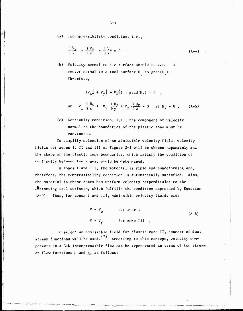
Ä-4
(a) Incompressibility condition, i.e.,
_„2L + J_£ + _1__Z. = o . (A-4) * x ) y 3 z v '
(b) Velocity normal to die surface should be zero. A
vector normal to a tool surface H is gradUL).
Therefore,
(Vxi + Vyl + Vzk) • grad(Ht) = 0 ,
°r Vx T^ + Vv T71 + Vz 11^ = ° «t Ht - 0 . (A-5)
(c) Continuity condition, i.e., the component of velocity
normal to the boundaries of the plastic zone must be
continuous.
To simplify selection of an admissible velocity field, velocity
fields for zones I, II and III of Figure 2-1 will be chosen separately and
the shape of the plastic zone boundaries, which satisfy the condition of
continuity between two zones, would be determined.
In zones I and III, the material is rigid and nondeforming and,
therefore, the compressibility condition is automatically satisfied. Also,
the material in these zones has uniform velocity perpendicular to the
vÄntacting tool surfaces, which fulfills the condition expressed by Equation
(A-5). Thus, for zones I and III, admissible velocity fields are:
V ■ V for zone I (A-6)
V * V for zone III .
To select an admissible field for plastic zone II, concept of dual (7)
stream functions will be used. According to this concept, velocit> com-
ponents in a 3-D incompressible flow can be represented in terms of two stream
or flow functions \> and . , as follows:
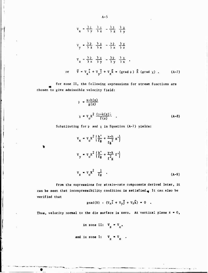
A-5
v = 11 2A _ ±JL li x lylz ) z } y
v .11 ll -11 lJL y 3 z } x ) x } z
v = 11 ±1 .11 IX z 3 x 3 y ]y )x '
or V -Vi + v] + v!= (grad <|> ) X (grad x) • (A-7) A y z
For zone II, the following expressions for stream functions are 41
chosen to give admissible velocity field:
V g(z)
x V TUT ' (A'8)
Substituting for J/ and x in Equation (A-7) yields:
x o 1 fg 2 I
V .VR2|f + Üf.| y o I fg .2 / £g f.
V ■ v R — Vz o fg • (A-9)
From the expressions for strain-rate components derived later, it
can be seen that incompressibility condition is satisfied.^ It can also be
verified that
grad(H) • (VXT + Vy} + Vzlt) - 0 .
Thus, velocity normal to the die surface is zero. At vertical plane z • 0,
in zone II: V ■ V , z o
and in zone It V - V z o

A-6
Thus, the velocity V normal to surface z = 0 is continuous. Similarly, it
can be shown that: across the surface z = L, the normal velocity is continuous.
Thus, the velocity field given by Equation (A-9) is kinematically admissible.
This velocity field together with Equation (A-6) forms a complete admissible
velocity field for the extrusion process, and can be used to formulate an
upper-bound solution.
Strain-Rate Field
In zones I and III, all the components of the strain-rate tensor
are zero. For zone II, the strain-rate components are given by:
) V X = XX ~) X
2 g' V R -AT 0 f 2
fg
yy 3 y
2 f • v R -=r o c2
f g
zz 3 z VR2 [-r + 4- o I 2 2
f 8 g f
^xy 2 1 1 y W > VX + BVv , . 0
) x
Eyz " 2 h z * } y
o 2 \fg 2k'f
f28
+ y-k
fg
f"
f2*
2f ,2
f3s s» f2g
£ 2h: Sx I xz
v a2 J n:. 2h^Ll _
° 2 lf* f,2 h'f
f2. + x-h L 2 3 .2 2
fR fg f g <*
(A-10)

A-7
Rate of Energy Dissipation and Extrusion Pressure
By the application of the Upper-Bound theorem, expressions for
the rate of energy dissipation, E, and the mean pressure required to extrude,
P, which would give values that are larger than the actual values can be
obtained. As sum of various components, the rate of energy dissipation, E, is
given by:
E»Ep+E1+E2+Efd+Efc+Ef£ . (A-ll)
The rate of energy dissipation, E , due to plastic deformation in zone II is
given by:
*P ■ /T {ff s /KT^J d*dy dz
zyx
1/2
- — Iff 5 \l/2[t 2 + i 2 + e 2j +£ 2 + e 21 dx dy dj /J zyx L I xx yy zz / yz zx J
(A-12)
The rate of energy loss due to tangential velocity discontinuity at the
boundaries of plastic zone, or at material-tool Interfaces, is given by:
Er - fT T|Av|dSr . (A-13)
T is the shear stress at the surface I', Av is the tangential velocity
discontinuity, and S is the surface area.
The total rate of energy dissipation is equal to the rate of energy
supplied by the ram, E , which is given by: K
2 - E - n R P V . (A-14)
Substituting for various components of rate of energy dissipation in Equation
(A-ll), an expression for the mean extrusion pressure P can be obtained, in
functional form, P may be written as:
P - P(A,B,C,D,R,V0,Lc,L,La,g(r),fU),h(E),k(z),md,mc,o) (A-15)

A-8
In the above expression, the friction at the material-tool interlace is
expressed by:
T = mo // 3 . (A-16)
T is the shear stress due to friction at the tool surface; m is called the
friction factor and is assumed to be constant over the tool surface for given
conditions of lubrication, temperature, die and billet materials, ö is the
flow stress of the material and it is assumed to be a function of the total
strain (e), strain rate (e) and temperature.
The pressure for given values of the parameters (A,B,C,D,R,V0,g,
f,h,k,L) was obtained numerically. The deformation zone, zone II in Figure
2-1, was divided into an orthogonal grid system. The grid was so chosen that
it coincided with the stream surfaces (x ■ Constant,]; - Constant). Thus, the
volume elements of the grid could be considered as elements of the stream
tubes. The total strain at the center of a volume element was obtained
numerically by integrating along the center of the corresponding flow tube.
Knowing the total strain, strain rate and temperature, the tlow stress can be (8)
obtained from flow stress data.
Computer Program
Based on the foregoing analysis, a computer program, called EXTRUD,
was developed to simulate the complete extrusion process. A listing of the
computer program is included at the end of this Appendix. The following
simplifications have been made in the computer program.
(1) Terms for friction at the container and d:t land are
not included.
(2) The center of the elliptic shape coincides with the
center of the billet. Thus, C and D are taken to
be zero.
The program, however, can be easily generalized to include the effect of
friction at container and die land, and the offset in the position of
elliptic shape.

A-9
Input to the Computer Program
The following
DETAIL
DEBUG
OPTM
R
AL
A,B,C,D
AM
TEMP
VO
C1,C2,C3,C4, C5,C6,C7,C8
NX.NZ
NCODE
PG(4,3)
information is needed as input to the program:
.FALSE, when the detailed information
regarding velocity and strain distribution
is to be printed.
.FALSE, when the step-by-step calculations
are to be printed for debugging the program.
.TRUE, when the optimal shape of the die is
to be determined.
Radius of the billet.
Length of the die.
1 Dimensions of the ellipse (Figure 2-1).
' Friction shear factor (ny). 1 Initial temperature of the billet.
1 Speed of the ram.
> Coefficients used in defining functions
g(z), f(z), h(z), k(z) in polynomial form.
In this program, only Cl and C3 are used.
> Number of divisions along the x and z axes,
respectively, in which the deformation zone
is divided for setting up a grid system.
> Specifies the shape of the billet. NCODE is
equal to one for the cylindrical billet.
• Arrays of size 4x3. Initial guesaes of
optimal Cl, C3, and AL are input through this
array. These guesses are used by th- subrou-
tine SIMPLX to determine the optimal values
of Cl, C3 and AL by the simplex method of
function minimization.

A-10
I Output from the Computer Program
Cl, C3, AL ■ For OPTM - .TRUE., optimal values of parameters
Cl, C3 and AL are printed. Fur OPTM « .FALSE.,
input values of Cl, C3 and AL are printed.
ALOAD - Total load required to extrude.
PRES • Extrusion pressure
TENERG * Total rate of energy required for the extrusion
process.

A-11
Nomenclature
R - Radius of ehe billec.
A • Half major axis of Che elliptic shape.
3 ■ Half minor axis of Che elliptic shape.
C - Offsec of ehe cencer of ehe elliptic shape
along x axis.
D ■ Offsec of ehe cencer of ehe elliptic shape
along y axis.
L • Length of the streamlined die in axial
direction (direction along ehe motion of the ram)
7 » Velocity of the ram. o ' V - Velocity of the emerging product.
Vx.Vy.Vz ■ Components of the velocity vector in
x, y and z directions.
i ■ Strain-rate tensor.
5 • Flow stress of ehe material.
E ■ Total race of energy dissipation.
E ■ Sat« of energy dissipation due to plastic P
deformation in zone II (Figure 2-1).
E.,E, • Sacs of energy dissipation due to tangential
velocity discontinuity at boundaries z • 0 and
z • L, respectively, of the plastic zone. ... - — E E E fd' fe' fi - Race of energy dissipated due to friction
- at material die, material container, and
material die-land interfaces, respectively.
m.,m • Friction shear factor over die and container o c surfaces, respectively.
F ■ Mean extrusion pressure.
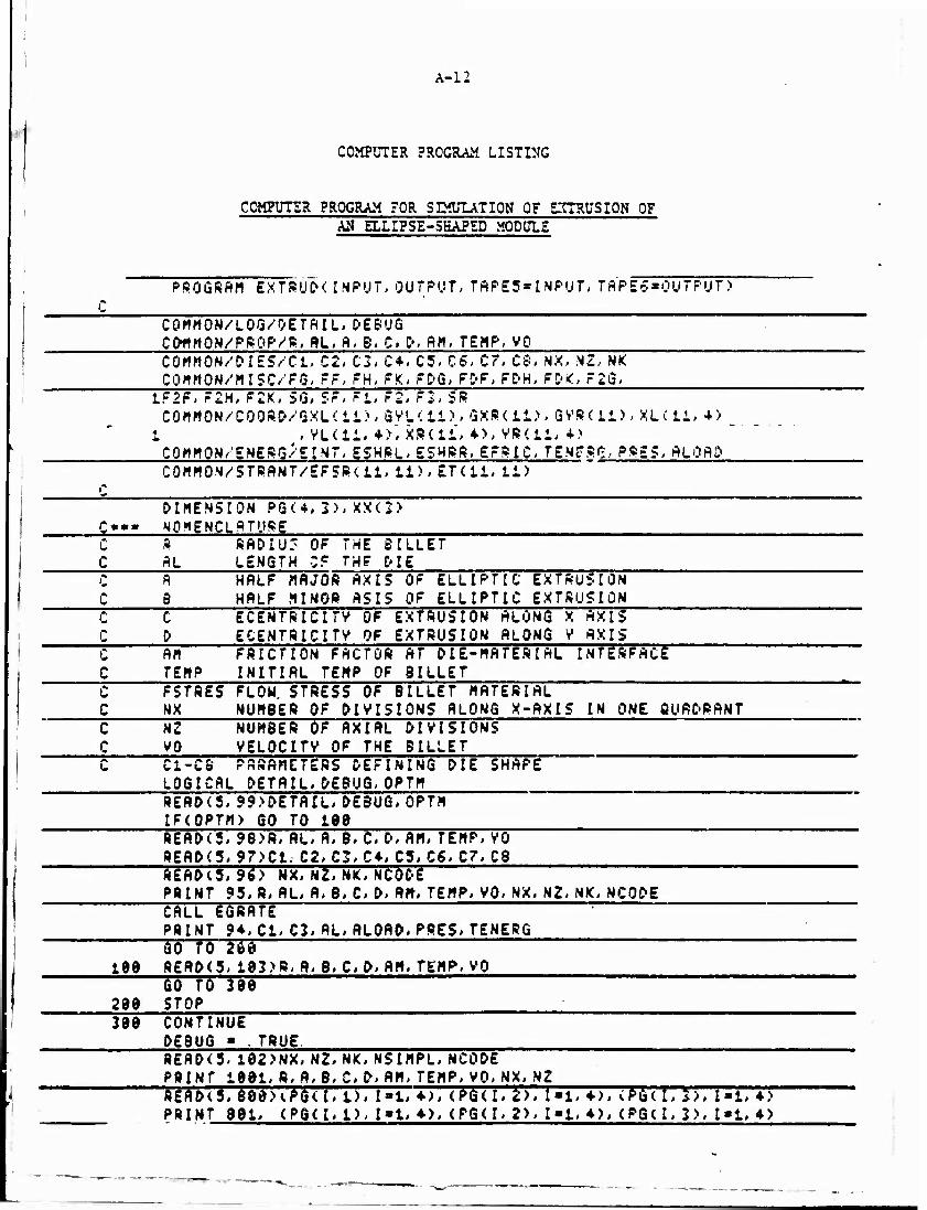
A-I:
COMPUTER PROGRAM LISTIMG
COMPUTER PROGRAM FOR SIMULATION OF EXTRUSION OF AN ELLIPSE-SHAPED MODULE
PROGRAM EXTRUP< INPUT,OUTPUT,TAPES»!NPUT, TAP£5*OUTPUT)
COHMON/LOG/DETAIL, DEBUG CfrHHON/PROP/S, AL, A, S, C, P, AH, TEHP, VO COHHON/'DIES/Cl, C2, C3, C+, C5, CS. Cr, CS, NX, NZ, NK COHHON/HISC/FG, FF, FH, FK, FDG, FpF, FDH, FPK, F2G,
1F2F, F2H, F2K, 5G, SF, rT F2J FT SR COMMON/COORD/GXLdl), GVL'.il), SXRdi), GVS(ii), XLCli, +>
1 , VLCli,+>", XBC11, 4), VR'.ll,+> CQHHQN/ENSRG/EINT,ESHRL,ESHRR,EFRIC,Tg.NgSS,PRE5,ALQAP COMMON/STRANT/SFSRdi, 11), ETC11, 11)
DIMENSION PG<*,3), XX(3> Q«» NOMENCLATURE C R RADIU' OF THE BILLET C AL LENGTH CF THF ME
A HALF MAJOR AXIS OF ELLIPTIC EXTRUSION B HALF MINOR ASIS OF ELLIPTIC EXTRUSION
C " C ECENTRICITV OF EXTRUSION ALONG X AXIS C 0 ECENTRICITV OF EXTRUSION ALONG V AXIS "C AM FRICTION FACTOR AT DIE-MATERIAL INTERFACE
TEHP INITIAL TEMP OF BILLET C FSTRES FLOW STRESS OF BILLET MATERIAL C NX NUMBER OF DIVISIONS ALONG X-AXIS IN ONE QUADRANT C N2 NUMBER OF AXIAL DIVISIONS C VO VELOCITV OF THE BILLET
Ci-CS PARAMETERS DEFINING DIE SHAPE LOGICAL DETAIL,DEBUG, OPTM READ<5,99>DETAIL, DEBUG, OPTM IF(OPTM) GO TO 188 READ<5, 98>R, AL, A, B. C, D, AM, TEMP, VO BEAP<5. 97>C1. C2, C3, C», C5, C6, C7, CB ft£AP<5, 96) NX, NZ, NK, NCODE PBTNT 95, B, AL, A, B. C, P. AM, TEMP, VO, NX, NZ, NK, NCODE
CALL EGRATE :
PRINT 94, Cl. C3, AL, ALOAP, FRES, TSNERG GO fd 275 188 8£AP<5, 183>B, A, B, C, P, AM, TEMP, VO
GO TO 388 288 STOP 388 CONTINUE
DEBUG « .TRUE 8EAP(3. 182>NX, NZ, NK, NSIMPL, NCOPE PRINT 1881, R. A. B, CD, AH, TEMP, VO, NX, NZ REAP(5, 688X.PGU, 1), I»l, «•>, (PG(I, 2>, I»l, ♦), (PG(I, 3), 1*1, ♦ > PRINT 881, <PQ(I, 1), I»l, 4), (PG(I,2>, !■!,♦), (PG(I, 3>, 1*1, ♦>

A-13
C*** MINIPIIZflfION OF EXTRUSION PRESSURE BV SIMPLEX METHOD CALL SIMPLX<PG, 2, 4, 9. 3, 9. 5. 2. 5, XX, . 991, 49, NSIMPL) NX1*NX + : DETAIL ■■ FALSE. Cl' ■xx(i;
<xx<2: AL»XX<3 PRINT 1 995 CALL EQRATE PRINT 1991, Cl, C3, AL» ALOAD, PRES, TENERG
94 FQRMATC1H ,/V29X,'OUTPUT FROM THE PROGRAM EXTRUD'/// 1 19X, ' VALUE OF DIE PARAMETER, Cl »',E15. 6// 2 2
19X, ' 19X, '
VALUE OF DIE PARAMETER,C3 «',E15. 6// VALUE OF DIE LENGTH, MM ■',£13.6//
4 3
19X,'TOTAL FORCE REÖD. TO EXTRUDE, N 19X,'PRESSURE REQUIRED TO EXTRUDE,NN/SQ
*', E15. 6// H*' , E15. 6//
6 19X, 'RATE 95 F0RMAT<1H1,//29X,
OF ENERGV DISSIPATION,N. HM/SE 'INPUT DATA TO THE PROGRAM EX
C*', El5. 6//> TRUD'///
1 19X,'RADIUS OF THE BILLET, MM ■', F19. 2// 2 19X,'LENGTH OF THE DIE, MM »', F19. 2// 3 19X,'DIMENSIONS OF ELLIPTIC EXTRUSION ',/ 4 19X,'HALF MAJOR AXIS, MM »', F19. 2// 5 19X,'HALF MINOR AXIS, MM ■', F19. 2// 6 19X,'ECENTRICITV ALONG X AXIS, MM «', Fi&. 2// 7 19X,'ECENTRICITV ALONG V AXIS,MM ■', F19. 2// 8 19X,' ',/ 9 19X,'FRICTION FACTOR AT INTERFACE «',F19. 2// 1 19X,'INITIAL TEMP. OF THE BILLET, C *', F19. 2// 2 19X,'VELOCITV OF THE BILLET,MM/SEC »'. F10. 2// 3 19X,'NUMBER OF Dlv SIONS ALONG X-AXIS «',119// 4 19X,'NUMBER OF AXIAL DIVISIONS »',119// 5 19X, 'INDEX FOR BILLET SHAPE «',119//' 6 19X, 'INDEX FOR DIE SHAPE ■',I19/>
96 F0RMAT(4I19 FoRHftT* 5TS
98 F0RMAT<9F6 95 FöRHAT<3L4> 192 FORMAT(3I10>
"m—roTjnrn
>
4)
1991 FORMATdHl, TST.
4> //29X,'INPUT DATA TO THE PROGRAM EXTRUD'///
»' , f-18. 77T RADIUS OF THE DIMENSIONS OF TTffLT
BILLET,HH ELLIPTIC EXTRUSION
AXIS, MM
1 3 T
19X. ,/ iö«,'HALF HAJCR 19X. 'HALF MINOR
-',Fia. 2// ■'.Fie. 2// AXIS, MM
T ? T
iWPT&wrwTZTV} ffcmre s BTTTHTH 19X,'ECENTRICITV ALONG V AXIS,MM
•'^10.2// ■',F10. 2//
T53T lax.
T7- ■',F19. 2// FRICTION FACTOR AT INTERFACE
BILLET,C "=',F19. 2// «', F18. 2// ■Mi*//—
1 2
19X, ' INITIAL TEMP. OF THE 19X,'VELQCITV OF THE BILLET,HH/SEC 19X,'NUM8ER OF DIVISIONS ALONG X-AXIS 19X,'NUMBER OF AXIAL DIVISIONS
3 4 110/>
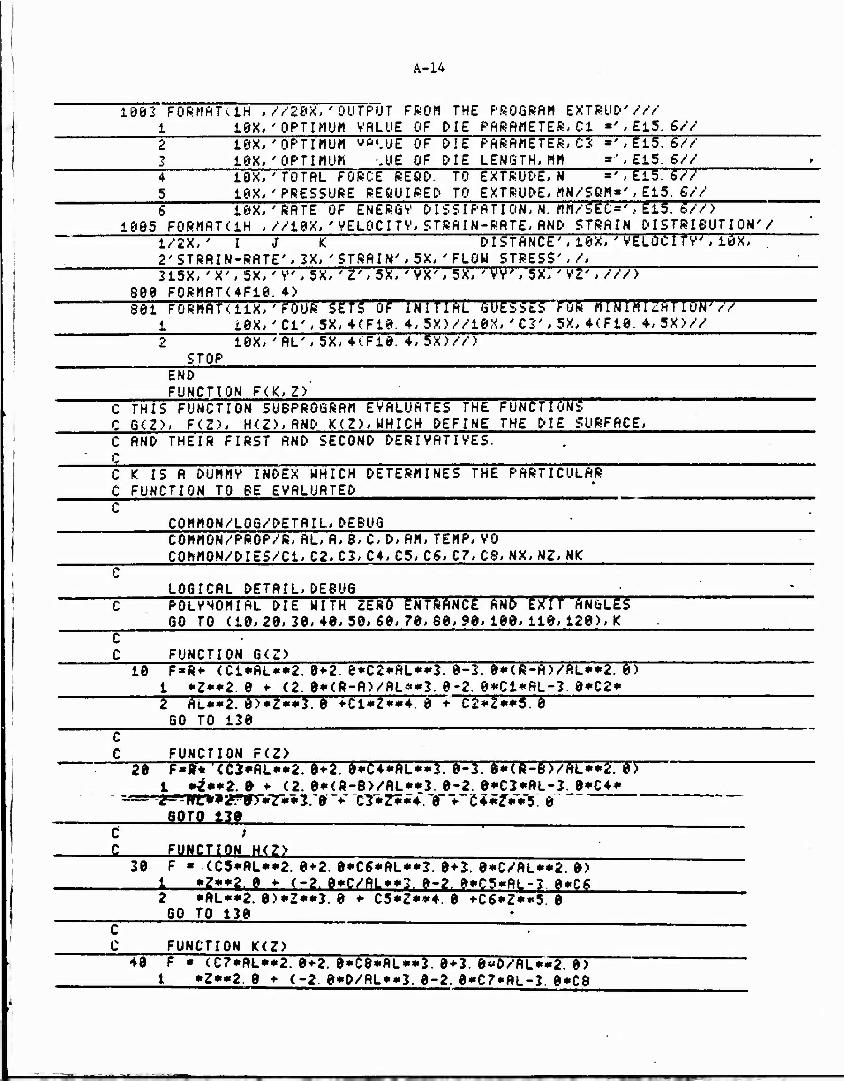
A-14
1003 FQRMATvlH , //20X, 'OUTPUT FROM THE PROGRAM EXTRUD' /// 1 18X,'OPTIMUM VRLUE OF DIE PflRftHETER, Cl = ', E15. 6/V 2 IW, 'OPTIMUM ye'.UE OF 0!E PARAMETER, C2 «' * E15. 6// 2 18X,'OPTIMUM gig OF DIE LENGTH, MM = ',E15. g// 4 10X, ' TOTAL FORCE REQO. TO EXTRUDE,« = ', E15. 6/Y 5 19X, 'PRESSURE REQUIRED' TO EXTRUDE, MN/SQM=', E15. £// 6 10X, 'RATE OF ENERGY' DISSIPATION, N. MM/SEC=', E15. S77) ~~""
1005 FORMATdH , //18X, ' VSLOCI TV, STRAI N-RATE, AND STRAIN DISTRIBUTION'/ 1/2X, ' I J K DISTANCE', 10X, 'VELOCITY", 10X, 2'STRAIN-RATE', 2X, 'STRAIN', 5X, 'FLOH STRESS',/, 215X, 'X', 5X, 'V, 5X, 'Z', 5X, ' VX', 5X, ' VV, 5X, ' VZ', ///) ^~"
880 FORMATC4F10. 4) 801 FORMAT<iix,'F^OUR Sgfs" of INITIAL GUESSES füR Fmn7rr7ÄTTT7fr77
1 jQX, 'Cl', 5X, 4(F10. 4, 5X)//18X, 'Ci:', 5X, 4<F10. 4, 5X)// 2 10X, ' AL', 5X, 4(Fi&. 4, 5X)//) STOP
END FUNCTION F(K, Z) ' ^ C THIS FUNCTION SUBPROGRAM EVALUATES THE FUNCTIONS ~"™"™~ ' " C 6<Z>, F<Z>, H<Z),AND K(Z),UHICH DEFINE THE DIE SURFACE, C AND THEIR FIRST AND SECOND DERIVATIVES.
C K IS A DUMMV INDEX WHICH DETERMINES THE PARTICULAR C FUNCTION TO BE EVALUATED '
C0MM0N/L06/DETAIL, DEBUG COMMON/PROP/R, AL, A, B, C, D, AM, TEMP, VO C0MM0N/DIE5/C1, C2, C3, C4, C3, C6, C7, C8, NX, NZ, NIC
C LOGICAL DETAIL,DEBUG -
C POLYNOMIAL DIE WITH ZERO ENTRANCE AND EXIT ANCLES GO TO (10, 20, 20, 40, 30, 60, 70, 60,90, 100, 110, 120), K
C C FUNCTION G(Z)
10 F»R* <C1*AL**2. 0 + 2. 0*C2*AL**2. 0-2. 0*<R-A)/AL**2. 0) 1 »Z»»2. 0 » (2. 0»<R-A)/AL»»3. 0-2. Q*Cl»AL-2. 0»C2»
2" AL**2. 8>«Z**3. 0 ♦ C1*Z**4. 0 *• C2*Z**5. 0 GO TO 120 C C FUNCTION F(Z>
28 F»&* <CJ*AL**2. 0+2. 8»C4*AL»*2. 0-3. 8*<R-B>/AL**2. 0> 1 *Z**2.9+ (2. 8*<R-B>/AL**2. 8-2. 8»C2«AL-3. 8*C4*
,!z«Tfr>»2rrr«?r**r:$ v CT*Z***. T♦~e4*zv*5. a SO™ 12»
C ; _C FUNCTION H<?>
30 F « <C5*AL**2. 8*2. 8*C6*AL**2. 8*2. 8*C/AL**2. 8> 1 »Z»»2 8 » (-2. 8»C/AL»»2. 8-2. 8»C5«RL-3 8«CS
2 *AL**2. 0)*Z«*3. 8 *■ C5*Z**4. 0 +C6*Z**5 0 GO TO 120
c : C FUNCTION K(Z)
48 F * <C7*AL**2. 8*2. 8*C8*AL**2. 8+2. 8*«D/AL**2. 8) 1 »Z»»2. 8 » (-2. 8»D/AL»»2. 8-2. 8*C7*AL-2. 8*C8
~TT n ir IT

A-15
2 *ftl_**2. 8>*Z**2. 8 + C7*Z**4. 8 + C8*Z**5. 8 GO TO 130
C C FUNCTION S'(Z> - FIRST DERIVATIVE OF 6(Z)
58 F = 2. 8*<Cl*flL**2. 8 + 2. 8*C2*AL**3. 8-3:. 8*<R-H>/ 1 AL»*2. 8>»Z + 3. 8*(2. 8»<R-R)/flL»*3. 8-2. 8*C1
*AL-3. 6*C2*Al**2. 8> *Z**2. 8 + 4. 8*C1*Z**3. 8 c
2 + 5. 0*C2*Z**4. 8 60 TO 128
FUNCTION F'(Z> - FIRST DERIVATIVE OF F(Z) F » 2. 8*<C3»AL»»2. 8 + 2. 8»C4»AL»*3. 8-3. 8»<R-B>/
1 AL**2. 9>*Z + 2. 8*<2. 8*( R-£')/AL**3. 8-2. 8*C3 2 »RL.-3. 8»C4»AL»*2. 0)»Z**2. 8 + 4. 8»C3*Z**3. 8 i + 5. 8*C4*Z**4. 9 GO TO 128
C 69
c c FUNCTION H'<Z> - FIRST DERIVATIVE OF H<Z)
70 F » 2. 0*(C5*AL**2. 8+2. 8*C6*AL**2. 8 + 2. 8*C/AL**2. 8> 1 «Z + 2. 6*<-2. 0*C/Al**2. 0-2. 0*C5*AL-2. 8*C6*AL** 2 2. 8)*Z**2. 0 + 4. 8*C5*Z**2-. 8 + 3. 8*C6*Z**4. 8 GO TO 120
C C FUNCTION K'(Z> - FIRST DERIVATIVE OF K<Z>
88 F* 2. 8*<C7*RL**2. 8+2. 8*C8*AL**2. 8 + 2. 8*D/AL**2. 8) 1 *Z + 3. 8*<-2. 8*D/AL**2. 0-2. 8*C7*AL-2. 8*C3*AL** 2 2. 0>*Z**2. 0 + 4. 0*C7*Z**2. 0 + 5. 0*C8*Z**4. 0 GO TO 128
C C FUNCTION 6 '<Z> - SECOND DERIVATIVE OF G(Z)
90 F » 2. 0*<O1*AL**2. 8 + 2. 0*C2*AL**2. 0-2. 0*<R-A>/AL 1 **2. 0) + 6. 0*<2. 0*(R-A>/AL**2. 0-2. 0*Cl*AL-2. 0 2 *C2*AL**2. 0>*Z + 12. 0*Ci*Z**2. 0 + 20. 0*C2*Z**2. 0 GO TO 120
*
C C FUNCTION F"<Z> - SECOND DERIVATIVE OF F(Z) 109 F » 2. 0*<C3*AL**2. 0 + 2. 0*C4*AL**2. 0-2. 0*<R-B,VAL
1 **2. 0> + 6. 0*(2. 0*<R-0>/'AL**2. 0-2. 0*C2*AL-2. 0 2 *C4*AL**2. 9)*Z + 12. 0*C3*Z**2. 0 + 20. 0*C4*Z**2. 0 60 TO 120
C C FUNCTION H"(Z> - SECOND DERIVATIVE OF H<Z> 110 F ■ 2. 0*<C5*AL**2. 0+2. 0*C6*AL**2. 0+2. 8*C/AL*«2. 0>
1 +6. 0*(-2. 0*CAL**2. 0-2. 0*C5< AL-2. 0*C6*AL**2. 0> 2 *Z + 12. 0*C3*Z**2. 0 + 28. 0*CS*Z*«2. 8 . GO TO 120
C C FUNCTION K"CZ> - SECOND DERIVATIVE OF K<Z> •
129 P 1 +6. 0*<-2 0*D/AL**2. 0-2. 8*C7*AL-3. 0*C8*Al**2. 0) 2 *Z + 12. 0*C7*Z**2. 0 + 20. 0*C8*Z**2. 0 BO TO 120
■c : 120 RETURN

A~16
END SUBROUTINE FUMC(Z)
c c THIS SUBROUTINE CALCULATES Vr'9I0US FUNCTIONS FOR c c
GIVEN VALUE of Z
COP^ON/LOG/DETAIL, DEBUG COhMON/PROP/R, RL, A, B, C, D, Art, TEMP, VO COMttON/DIES/Ci, C2, C2, C4, C5, 06, 07, CS, NX, NZ, NK COrtHON/MISC/FG, FF, FH, FK, FDG, FDF, FDH, FDK, F2G,
C 1F2F, F2H, F2K, SG, SF, Fi, F2, Fl, SR
LOGICAL DETAIL,DEBUG F6»F<1,Z> FF=F<2,Z> FH*F<3,Z> FK*F(4,Z) FD6*F<5, Z) FDF*F<6,Z> FDH*F<7\ Z) FDK*F<8, Z> F26*F<9,Z> F2F«F(iO,Z) F2H»F<11,Z) F2K«F<12,Z> S6*FG**2. 0 SF*FF**2. 0 Fi*FF*SG F2*FG*SF SR»R**2. 0
-
F3»FF*FG IF(DEBUG> GO TO 62
4 L84 NRITE<6, 104> FORHRTC1H ,55X,'FUNC(Z)'>
: L85 WRITE<6, 105>Z, FG, FF, FH, FK, FDG. FDF, FDH, FDK, F2G, F2F, F2H, F2K FORHATC6F10. 6, A 7F10. 6)
63 CONTINUE RETURN END FUNCTION EFFR(X.V>
C C THIS PROGRAM CRLCULRTES THE EFFECTIVE STRAIN RATE C
COtrtON/LOG/DETAIL.DEBUG COHrtON/PROP/R, AL, Ri B, C, t>. AH, TEMP, VO COHHON/'DIL'S/'Cl, C2, C3, C4, C5, C6, C7, C8, NX, NZ, NK C0HH0N/MISIVP6, FF, FH, FK, FDG, FDF, FDH, FDK, F26,
1F2F, F2H, F2K, 56, SF, Fl, F2, F3, SR C
LOGICAL DETAIL,DEBUS C STRAIN RATE CO**3<£NTS
EXX »<SR*FDG/Fi;*VO EVV «<SR*FDF/F2>*V0 EZZ » -<EXX»EVV>

A-17
» 0 a g. 5»SR» (F2K/F2-2. »FDK»FDF/F2-FDK*FDG/F1» <V-FK)*<F2F/F2-2. *FDF*FDF/<F2*FF>-FDF*FD6/'<5G*SF>>>*V0 » 9. 5»SR» (F2H/F3-2. »FC'H*FPGyFl-FDH*FC'F/F2+- <X-FH>*<F2G/frl-2. *FDG*FDG/<F1*FG>-FDG*FDF/<SG*SF>>>*V0 ■ <2. /SQRTCJ. )>*(. 5*<EXX*EXX + £VV<*l!r'V + EZZ*EZZ>
EXV EVZ
1 SXZ
1 <X-FH>*<F2G/frl-2. *FDG*FDG/<F1*F6)-FDG*F(>F/<SG*SF>>>*V0 EFFR»<2. /SQRTC3. )>*(. 5*< EXX»EXX+£VV* 1VV»EZZ*EZZ>
1 +EXV*EXV*EVZ*EVZ*EXZ*EXZ>**. 5 IF<[>£SUG> GO TO 28 URITEtS, 19)
10 FORMATdH , 55X» ' EFFR( X^V)' ) URITEC6, 15)X, V, EXX, EVV, EZZ, EXV, EVZ, EXZ, EFFR
15 _F0R_MflT(9F8_J_)_ _ 20" CONTINUE
RETURN END SUBROUTINE GRDCZL,ZR)
C THIS SUBROUTINE GENERATES GRIP POINT? IN THE PLANE C SECTIONS AT Z»ZL AND Z«ZR _C
COMIION/LOG/DETAIL, DEBUG COHHON/PROP/R, AL, A, B, C, D, AH, TEHP, VO CQNMON/DIES/T1, C2, C2, C4, C5, C6, C7, CS, NX, NZ, NK COHHON/HISC/FG, FF, FH, FK, FDG, FDF, FDH, FDK, F2G,
1F2F, F2H, F2K, SG, 5F, Fl, F2, F2, SR COHttON/CQORD/GXL<ll>,GVL(ll), GXR(ll), GVR(ll), XL(11, 4)
f , VL(11, 4>, XR<11, 4>, VR(11, 4)
DIMENSION GX(ll),6V(11) LOGICAL DETAIL,DEBUG NX1«NX*1 ITER«1 Z-ZL IF <A8S(Z>. LT. 1. 8E-4>G0 TO 39 P"RTVTOUS RIGHr DO 18 1*1, «XI
GXltb-GXR^n" 18 GVL(I>«SVR<I)
SECTION IS NEU LEFT SECTION
Tff" TTÜW Z«ZR
ir"inr-T7i77r AV«F<2, Z> ATITF <"NTT~
6X<1>»8. 0 GV(NX1)»AV
Ai« 2. e»Ax»(ie. AD—<9. /18
/tl. >/ANX WAIWANK-I. >
CALCULATE THg CgüffFIWTn DO 40 J»2.NX1 TFTNI?
ör GRID PÖIMT5 rs A STCTTO
M. l) Gö fö 52 ' IF(J SQ 2> 6X(J)»A1 IF(J NE. 2>GX(J>«GX(J-1>*(GX<J-1>-GX(J-2))*AD GO TO 35

A-18
22 CONTINUE E1=J-1 •
E1 = E1/FINX GX(.J>*E1*AX *
C 55 CONTINUE
SECTION IS ELLIPTIC
C IFCNK. EÖ. i)GV<NX+2-J)»SeRT(ABS(l. 8-<6X(J>/AX>**2>>*AY SECTION IS RECTANGULAR ■
C IF(NX. EÖ. 2)GV(NX + 2-J)*(i. 8-Ei)*AV SECTION IS TRIANGULAR
48 IF<NK. EC. 2>GV<NX+2-J>=(l. 8-El)*AV CONTINUE
c IFUTER. EQ. t> 60 TO 88 HERE UHEN 2L IS NOT EQUAL TO ZERO DO 56 K*l, NX1 GXR<K>*GX<K:> *
58 GVRCK)=GVCK) GO TO 188
c 88
HERE WHEN 2*0 CONTINUE DO 78 I. »1, NXi 6XL<L>*GX<L>
c 79 GVL(L)*GV(L^
LEFT SECTION IS COMPLETED. 2C TO COVER RIGHT SECTION
f L88 GO TO 28 CONTINUE
■
IF<DEBUG> GO TO 55 URITE<6,181>
4 L81 FORMATdH ,25X,'GRD(ZL,ZR>',/> HRITE<6,102>ZL,ZR
J L02 PöftHATUftX. ^2L»J,Pi&. 5,i?«,;2R«J,Pid. &> NRITE(6,103)<GXL(I>,GVL(I),GXR(I),GVR(I).I«l, NX1>
183 53
PÖRHATUF15. 5> CONTINUE RETURN END
C SUBROUTINE STRAIN<ZL,ZR>
C C
THIS SUBROUTINE CALCULATES GRID POINT COORDINATES, ELEMENTAL VOLUMES, AND STRAINS AND STRAIN-RATES
C C
AT CENTRE OF THE ELEMENTS
töHMÖNVuRirVASURF. AVölUH COMHON/LOG/DETAIL,DEDUG COHMON/PROP/R, flL» A, B, C, D, AM, TEMP, VO COHMON/DIES/T1, C2, C2. C*, C5- CS. C7, C8, NX, NZ, NK CöHHuN/'HISCVPG, PP, I'H, PK, FD5, PDP, PDH, FDK, P2i,
1F2F, F2H, F2<. SG, SF, Ft, F2- Ft, SR JÖHHÖNyCööfiD/'GXLUt), GVU11>, SXR<il>, GYRUi>, XL<ii, 4>
t , VL(11, ♦>,XR(tl, ♦), VR<tl,4> CöHHöMVSTftANTVEPißUl, ti>, ETUi, ii> COMMON/ENERG/EINT.ESHRL,ESHRR,EFRIC,TENERG,PRE5,ALOAD
\
C LOGICAL DETAIL,DEBUG
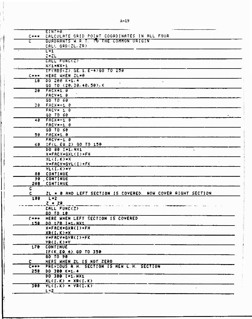
A-19
rnrrw. C*** CALCULATE GRID POINT COORDINATES IN ALL FOUR 1 QUADRANTS u.ft. T. lti THE CörirtON ORIGIN
CALL GRD<ZL,ZR> Lit ? X "* I
CALL FüNTTZI NX1-NX+1 IP(A65(Z>. 5£. 1. E-4)50 TO 1-56
O** HERE WHEN 2L»0 10 DO 20Ö K*i,4
GO TO (20, 20, 40, 50), K 20 FACX»1. 0
FACV*1. 0 GO TO 60
20 FACX«-i. 9 FACV» 1. 0 GO TO 60
40 FACX«-i. 0 FACV--1. 0 GO TO 60
30 FACX»1. 0 FACV»-i. 0
60 IFCL. EQ. 2) GO TO 150 DO 80 1*1, NX1 X»FACX*GXL<I)*FH XLU,K>«X V»FACV*GVL(I>*FK VL(I,K)«V
80 CONTINUE 90 .CONTINUE
208 CONTINUE C C ZL « 8 AND LEFT SECTION IS COVERED. MOM COVER RIGHT SECTION 100 L»2
Z » ZR CALL FUNC(Z) SO TO 18
£*•• HERE WHEN LEFT SECTION IS COVERED -Ufi DO 17Q I"l, NX.1
X«FRCX*GXRCI>+FH
V»FACV*GVR<I>*FK VR(I,K)»V
t?0 CONTINUE IF(K. Eft. »> 80 TO 35a
60 TO 98 C HERS WHEN ZL IS NOT ZERO "C^ PREVIOUS R H. SECTION IS NEU L. H. STcTTbTJ
250 00 389 K*l,4 DO 300 1*171X1 XL(I.K) * XRU, K> VL(I,K) ■ VR(I,K> L'2
A-20
zJzS CALL FUNC(Z) GO TO 10
'50 CONTINUE
IFCDEBUG) GO TO 265 NRITE<6,388) MR I TEC 6, 368 HCK, I* XL< I > K >* VL (I > K>> XR< 1/ K>, VR( l,K), I «i, NX1>
1, K«i, 4) 168 F0RMAT<2I18, 4F15. 6) 365 CONTINUE
C*** CALCULATE VOLUMES OF ELEMENTS C*** CALCULATE EFFECTIVE STRAIN-RATE AT CENTRE OF THE ELEMENT ~~~ C*** CftLCULflTE RATE OF ENERGV DISSIPATION DUE TO PLASTIC DEFORMATION
Z » (ZL + ZRV2. 0 CALL FUNC(Z) VZ * < S R / F 2 > * V Ö DO 408 K«l, 4 DO 408 1*1, NX IVAR*NX*1-I DLX*ABSCXL(I, K)-XL<(I+1)»K)) DRX*A8S<XR<I, K>-XR<<r*i), K> > DO 488 J*l, IVAR IFCJ. EQ. IVflR)FRC«8. 5 IFU. NE. IVAR>FAC»i. 8 DZ»ABS<ZR-ZL) DLV»flBS(VL(J-K)-VL(<J*1). fO > DRV«ABS<VR(J,K)-VR((J»1)<K>> VOLUHE »(DLX*DLV * DRX*DRV ♦. 5*< DLX*DRV+DLV*
t DRX))*DZ*FAC/3. IF<J. EQ. IVAR) GO TO 378 X« <XLtq»l),K>» XLtMO» X»(<I»1)«K>» XR< I, K> >/4. V« (VL<<J+i),K>+ VL(J,K)f VR<(J + t)< K)*VR(J, K))/4. GO TO 371 X« <XU!« K> + <1. /3. >*<XL<<!+1)< K>-XL<I, K> > *
1 XR<I,K>* (1. n. )»<XB<<I»l>.IO-XR<I, K)))/2. V « <VL<J, K> + <1. /3. )*<VL(<J*1). K)-VL(Ji H)> «-
t VR<J,K) t <!• 'I- )»(VB((J*l)i K)-VB(J,K)>)/2. 371 EFSRU, J)-EFFR<X, V)
ClFQc. ME. 1)60 TO 374 ET<I,J> ■ ET(I,J> * EFSRU, J>*( ZR-ZD/VZ
ftVQLUM»AVOLUM+ftBS(VOLUME) 274 CONTINUE
FL0H5 • FSTBES(ET<r>J). EFSR(I> J>, TEMP) EINT « EINT*FLOUS«VOLUHE*EFSR<I,J) IF(DETAIL) GO TO 373 VX « SR*V0*<FDH/F2*(X-FH)*FDG/'F1) W » S»*V0*(FDK/'F3*<V-FK)*FDF/F2)
<

A-21
VZ« SR*V0/F2 MRITECS, 272) I, J, K, X, V, Z, YX, VY, VZ, EFSR< I, J), ET< I, J>, FLOWS
- 72 F0RMAT-.2X, 315* 2X, 4-Fll. J, /, 5F11. 5) CONTINUE IFCDEBUG) GO TO 290 URITE'b, 280 >
- S0 FORMAT(1H * 55X,'STRAIN<ZL,ZR;', /> WRITEC6- 285>X, Y, Z, VOLUME, EFSR( I, J), ET( I, J>, FLOWS, EINT
J 35 90
FORMAT<8F10. 2> CONTINUE
499 CONTINUE RETURN END FUNCTION SURFCX1, VI, Zl, X2, V2, Z2, X2, V2, Z2>
C C THIS SUBROUTINE CALCULATES THE AREA OF A TRIANGLE
COMMON/LOG/DETAIL, DEBUG 512» SQRT(<Xl-X2)*<Xi-X2> +< Yl-Y2)*< Y1-V2) +(Zl-Z2)*(Zt-Z2> > 55:5» 5öftT(<:xi-H3>*<X2-X2.>*<YS-Y3>*<YS-Y2> * (Z2-Z3/*tZ2-23>!> S21» SQRT(CX2-X1)*<X2-X1) + < VJ-V1)*< Y2-Y1) *• ( Z2-Z1) *< Z2-Z1) > S * (0. 5»<S12*S22+S31>> SURF« S0RT(S*<S-S12)*<S-S22>*<S-Sn)) fteriiftN1
END
C FUNCTION DtSVELCX,V,INDEX)
c c
THIS FUNCTION SUBPROGRAM DEFINES VELOCITY DISCONTINUITY AT THE DIE SURFACE, AT THE ENTRANCE BOUNOARY<Z»0> AND,
c c
At THE exit BOUHDARY<Z»AL>.
COMMON/PROP/R, AL, ft. 8/ C, D, AH, TEMP» VO COMMON/DIES/C1, C2, C3, C*> C5, C6, C7, C8, NX* NZ, NK COMMON/MISC/FG, FF, FH, FK, FD6, FDF, FDH, FDK, F2G,
1F2F, F2H, F2K, SG, SF, Fl, F2, FJ, SR C
vx « SR*VO*<FDH/FJ*(X-FH;*FDG/FD vv » 5ft#v'ö*<rD*/,PSWY-nü*.rDi-/,F2> VZ« SR*VO/F2
C GO TO (10, 10,20), INDEX VELOCITV DISCONTINUITY AT ENTRANCE OK EXIT BOUNDARV
10 DISVEL « SQRT<VX*VX*VV*VV> SO TO 28
C 20
VELöfilTV DISCONTINUITY AT ME SUftfAfcE DISVEL ■ SQRT<VX*VX*VY*VV*VZ*VZ)
20 RETURN END
c*** FUNCTION FSTRES<STRAIN, STRSAT,TEMP) THTS FUNCTION SUBPROGRAM CALCULATES FLO« STRESS
c c
AS" ft FUNCflON tit SfRAIN, STRAIN ftATC AND TEnf-EfcATuftE
FSTRES » 272. RETURN END SUBROUTINE ENERQV(ZL,ZR)
A-22
"]>** THIS SUBfiGUTINl'CflLCÜLRTES RATE OF ENERGV" D~I SSI PAT I ON C BETWEEN THE CONSECUTIVE SECTIONS Z = ZL AND Z = ZR C NZ SHOULD BE MORE THAN ONE C
COMMON/WRIT/ASURF,RVOLUM CQMMQN/LOG/DETRIL, DEBUG
COMMON/PROP/R, AL, A, B, C, D, AM, TEMP, VO C0MM0N/DIE5/C1, C2, Cl, C4, C5, C6, C?> CS, NX»NZ, NK
COMMON/MI SC/F6. FF, FH, FK, FDG, FDF, FDH, FOK, F2G, 1F2F, F2H, F2K, SG, SF, Fl, F2, F2, SR
COMMON/STRANT/EFSRdl, 11). ETCli, 11) COMMQN/COORD/GXUll), QVL(ll). GXR(li), GVR(ll), XL(11, 4)
'" 1 ~"~, VL<~il, 4),XR<11, 4), VR<11, 4) COMMQN/ENESG/EINT,ESHRL,ESHRR,EFRIC, TENERG, PRES, ALQAD
LOGICAL DETAIL,DEBUG
9 WRITEdS,21)
1 FORMATC1H ,55X.'mENERGV(ZL,ZR> ESHRL**. d ESHRR»0. 9 EFRIC»©. 9 CALL 5TRAIN(ZL,ZR)
C*m* SfiTc. OF ENERGV DISSIPATION DO 99 K«t« 4 DO 90 I»l, NX IVAR »NX1-1-I DO 90 J»l, IVAR FLOMS»FSTRSS<ET(I, J), EFSRU, J), TEMP) £** SHEAR DEFORMATION ENERGV
IF(R8S<ZL) ST. 1 E-4)S0 TO 68 T HERE WHEN ZL » 8
IF(J. EQ. IVAR) GO TO 40 FAC*1. 0 FACCG*8 S GO TO 58
40 . FRC»0 5 FACCG-C1.8/*. 0)
GO TO 50 —30 SAREA»FAC*(XL((I*1).K)-XL<I,<))*<VL((J*l>, K>-VL<J, K) ) SAREA « ABS(SRRER)
>T* XL<l.K>*pA£iG*(XL<(I*l>,K)-XL(I,K)> V ■ VL(J,K)»FflCC6»(VL<<J+l>, K)-VL(J, K) > mr. ar r OR. r ar r öR. *. ar n GO ns ss CALL FUNC(ZL)
55 CONTINUE DELV • A8S(DISVEL<X. V,i>> £SHRL«(FL0US/SCRT(2.))*DELV*SAREA ♦ ESHRL
60 IF(RBS<ZR-RL>. ST 1. E-4)G0 TO 8S ! HERE WHEN ZR - AL
IF(J. EO. IVAR) GO TO 79 FAC-1. 0 FACCS-0. GO TO 80
70 FAC»0. 5

A-23
FACCG*(i. 0/2. 0) GO TO 80
80 SAftEA*FAC*<:XR<( I>1>,K)-XR<I,K))*(VR<<J+i>,K>-VR<J, K>) SAREA = ABS(SAREA) X » XR(I, K>+FACCG*<XR<<H»1>, IO-XRU, K.'>> V = VR(J,K>+FACCG*(VRC(.J + 1),IO-VR(J,K)> IF<J. NE. 1. OR. I. NE. 1. OR. K. HE. i) GO TO 85 CALL FUNC(ZR>
85 CONTINUE DELV »ABSCDISVEL(X, V, 2>> ESHRR»<FLQMS/SÖRT(2. >>*DELV*SAREA + ESHRR
86 CONTINUE 1F\DEBUG,> 5T3 T6 5? :
WRITE<6, 8DFL0W5» SAREA, X, V, DELV, ESHRL, ESHRR 87 FORMAT* 7F11. J> 8? CONTINUE 90 CONTINUE
C** RATE OF ENERGV DISSIPATION DUE TO FRICTION DO 1ÖÖ ««1, * DO 180 !■!, NX J«NX+2-I SURFl*SURF(XL<r< K>, VL(J, K>, ZU XR<1, K>, VR<J, K),
1 Zft, XL<<I*1), K>,YL<<J-1>,JO,ZL) SURF2» SURF(XR<I, K>» VR< J, K),ZR,XL<(1*1)/K>, VL(CJ-l), K>,
i ZL, Xfl<<I+i>, K), VR(<J-i>, k>, ZR> ASURT-AeS(SURFl+SURF2)+ASURF
CALL FUNC(ZL> VI » prSVEL(XL<I>K)> VL(J.K),3) V>2 * DISVEL(XL<<I*1>, K>, VL<U-1>, K), J> CALL FUNC(ZR) Vi« t>isvzLimi.M.MKt.Kyrr> V4 « DISVEL(XR<(I*1>,K>,VR<<J-1>, K>, 3> AVEV • r7IT7J7VITVT77?" FLOUSi« FSTRESCETU,<J-i>>,EFSR(I,<J-1>>,TEMP) EFftlC » ETBTÜ77T aVS&ftTO. > )«<FlOU51»'ftVEV»<gUgFl+gUBF2>>*flW IF(DEBUG) GO TO 92 renm: »/2ft, ZL SUSPI, SüRT:, vi, va, TT: V4, FLOUSL SPRIC
92 F0RHATC5F12. ♦) 93 nnrmnje .
100 CONTINUE IP^gW6> 6Ö Tö ?j
MR ITE<6,113)EINT,ESHRL,ESHRR,SFRIC u3 PöRHAT<!4Fi5. *>
72 CONTINUE RETURN END SUBROUTINE EGRATE
COHHON/WRIT/ASURF,AVOLUH COMHQN/LOG/DETAIL,DEBUG COffflON/PROP/R, AL> A, B, C D, AH, TSHP, V'O COHMON/DIES/C1, C2, C2, C*, C5. C6, 07, C8, NX, NZ, NIC COHHON/HISC/FG, FF, FH, FK, FDG, FDF, FDH, FDK, F2G,
Ttlt, F2H, F2K, 5G, SF. FT P2, F3, 5ft COH«ON/COORD/GXL<il), GVL(ll). GXR(li), GVR(li), XLU1, 4)
.

A-24
i , VH'tt- 4>, XR< U, 4), Vftdi, 4) COMHPN/STRANT/EFSRai, 11) ■ ET < 11, 11 >
TüMMON/ENERG/EINT,ESHPL,ESHRR,EFRIC,TENERG,F'RES,ALÜHD LOG!CfiL DETAIL,DEBUG
Tm—DIVISION ALONG 2-AXIS rs IN AftiTHnATIC: pfiöfiSesSIöN "" C SET INITIAL VALUES TO ZERO TEINT,3 g ■
TESHRR = Q. 0 TESHRL»0. e TEFRIC'0 0
AVOLUM-0. ASURF«0.
NX1»NX>1 DO 15 K»l DO 15 1=1, NX1 GXL*. I >*0. G V L < I > s 0. GXR<I>=0 u V S». I > ■ 0. :<l< I, K)*0. VL< 11 K>»0. k.9< I, '<> «0. VR'-' I, K>»0. DO 15 J»l, NX1 E F 5 S■ * 11 J ■' * 0. ET. I, J>»0.
15 CONTINUE Z»0. 0 ILOOP«! ARA1 * 2.6*AL/<FL0AT<NZ)*<1. 0+A*A/<R*R>>> ARC'«-«. I. 0-A*A/(R*ft> >*ARAi/<. FLOAT^NZ-'-l. > ZL»Z ZR*Z+ARA1
10 CALL ENERGV<ZL, ZR.V
TEINT«TEINT*EINT TESHPL»TESHRL*I:SHRL T'ESHRR-TESHRR+ESHRR" TEFRIOTEFRIC + EFRIC IF((ZR-AL>. ST. -1. 0E-4) GO TO 20 IFdLQQP GT 22)G0 TO 52 ANEXT»<ZR-ZL)*ARD
ZR« ZR+ANEXT qo TQ ;*
20 CONTINUE TENERG TEINT * TESHRL ♦ 1ESMÄR ♦ TEFklC ALOAD ■ TENERG/VO PRE? » TSNERG/Q 14l592r»SR»V0>
2: •IRITEU. 22> FORMATC1H . 25X, EGRATE',/)
24 MP!TE<6, 24> TEINT,TESHRL,TESHRR, TEFRIC, TENERG, ALOAD, PRES F0RHRT(7rll. 2>
22 CONTINUE MRITE<6, 249)RSURF,AVOLUH

A-25
:4? F0SMAT<£Fl5' 6 RETURN STOP END FUNCTION MIN(XX, N> COMMON^PROP/R, AL, A, B, C, D, AM, TEMP, VO COMMON/DIESVCl, C2, C3, C + , C5, C6, C7, CS, MX, NZ, NIC COHMON/ENERG/EINT, ESHRL, ESHRR, EFRIC, TENERG,ARES,RLOAD DIMENSION XX<N) Ct«XX(t)
"~"~ C3«XX<2) AL»XX<3> CALL EGRATE «IN * PRES RETURN END SUBROUTINE SIMPLXtX, N, NPi, ALPA, BETA,SANA. XX,ELIMIT,LIMIT,NPR)
C*** THIS SUBROUTINE MINIMIZES ft FUNCTION OF N VARIABLES BV C SIMPLEX METHOD C DIMENSION STATEMENT IS TO BE CHANGED IF THE C MUM6ER OF INDEPENDENT VARIABLES EXCEEDS 7
DIMENSION X(NP1, N), V(6), XAVG<$>, XI ( 6 ), X2 ( 6>, XX ( N), 1ER0R<6),XAV<6),DIF<6>
C N IS THE NUMBER OF INDEPENDANT VARIABLES C (N»l) SETS OF INITIAL SUESSES OF INDEPENDANT VARIABLES MUST BE PRESCRIBED C IN THE ARRAV X(I,J), FOR I»t TO <N + 1>, AND J-i, N C ALPA IS REFLECTION COEFFICIENT, A POSITIVE CONSTANT LESS THAN 1
I C " BETA IS CONTRACTION COEFFICIENT, A POSITIVE CONSTANT LESS THAN 1 C GAMA IS XPANSION COEFFICIENT, A POSITIVE CONSTANT GREATER THAN 1
ALPAP » t. * ALPA BETAM « t. - BETA GAHAM » 1. - GAMA FN « FLOAT(N> FNP1 ■ FN + t. DO 12 J«l, N
13 ERQRCJ>«1111.
C C
NITER >.8 NPPP « 1
C* CALCULATE V(I> AT INITIAL P(I) DO 29 I«t, NPI DO 13 J>1, N
15 XX(J>»X(I.J> VCD • MIN(XX, N)
28 CONTINUE C 38 CONTINUE
A-26
C* PRINT ONLV WHEN REQUIRED NITER = NITER + t IFCNPR. Eft. 0>GQ TO 40 IF(NPPP. ME.NITER)GO TO 48 MPPP s NPF'P ? 2 WRITEcö,1091) NITER
1001 FORMAfizdrt,'NO. öFTTEfiflTIGN »Ml,/, 118X, ' PRESSURE', 5X, "ERROR IN CV , 5X, ' ERROR IN Cr ,
~~ 25X,'£RRQR IN AL',5X,'Cl', 18XVC5M8X, 'AL'/) DO 35 1=1, NP1
25 WRITE(6,1000)1,V(I),(ERQR(J),J*i,N), <X(I,J),J«l,N> 1000 F0RMAT(5X, 14» 7E18. 2) 40 CONTINUE
C CALCULATE HIGH AND LOU VALUES OF V (VH, HI) AND C THE POINTS FIT WHICH THESE OCCUR <PH, PL). ~~
VH = V<t> VL * V<1) IH ■ 1 IL « 1 DO 101 1*2, NP1 IF<V(I).QT. VH)GO TO 50 IF(V<I>. LT. VDGO TO 69 GO TO 101
50 IH • I GO TO 101
60 VL«V(I) IL » I
101 CONTINUE ~~~ C CALCULATE CENTEROID OF POINTS(PBAR) WITHOUT INCLUDING "E THE HIGH POINT(PH).
DO 112 J«l, H minn • 0. DO 184 I»l, NP1 rrn . ea. IH> GO TO 104— XAVG(J> « XflVG(J) + X(I,J)
104 CONTINUE 112 XflVG(J) « XAV6(J)/FN
DO 113 J«t, N 113 XKJ) « ALPAP*XAVG<J) - ALPA*X(IH,J)
CALCULATE V AT REFLECTION OF HIGH POINT(V*> VI • HIN<X1,N> IF(Vt . LT. VL) GO TO 280
C HERE IF V* IS LESS THAN VL 238 CONTINUE
DO 189 I»t, NP1 IF(l . EÖ. IH) GO TO 109 IF(V1 . QT. V(D) GO TO 688
189 CONTINUE GO TO 788
600 CONTINUE C V* IS GREATER THAN V(I) WITH I NOT EQUAL TO H
!r(Vl . GT. VH) GO TO 858 HERE WHEN V« IS LESS THAN VH
A-27
759 CONTINUE DO 115 J'L M 1 REPLACE PH BV P*
115 X(IH, J> * XKJ> V(IH) * VI
858 CONTINUE FORM P** BV CONTRACTION DO 116 J*l, N
116 X2<J) « BETA*X<IH,J) ♦ BETAH*XAVG<J> V2 « HINCX2,N) IF(V2 . QE. VH> GO TO 809
950 CONTINUE , C HERE UHEN V** IS LESS THAN VH . C REPLACE PM BV P»»
DO 117 J»l, N 117 X(IH, J> « X2< J>
V(IH) « V2 60 TO »09
C HERE UHEN V** IS GREATER THAN VH 800 CONTINUE
REPLACE ALL P(I)'S BV <P<I)+PL>/2 DO 105 1*1, NP1 DO 99 J»l. N X(I, J> « <X(I, J> * X(1L» J))/2.
99 XX<J> • X(I,J) V(I> » HINCXX,N)
105 CONTINUE GO TO 400
200 CONTINUE C HERE TF V* IS LESS THAN VL
EXPAND P* TO P** AND CALCULATE V** DO 118 J«l, N
118 X2(J> - GAHA*X1(J) ♦ GAHA«*XAVG<J) V2 ■ HIN<X2,N> IF(V2 . IT. VL) 60 TO *00
GO TO 700 "C HERE UHEN V** IS LESS THAN VL C REPLACE PH 8V P«»
300 CONTINUE DO 119 J'l. N
119 X(IH.J) - X2(/> V(IH> ■ V2 80 TO 400
780 CONTINUE i Hgftg ran Y« is ffSTRm rm vz
REPLACE PH 8V P» DO 121 J«l. H
121 X(IH,J) ■ XKJ) V(IH> » VI
400 CONTINUE
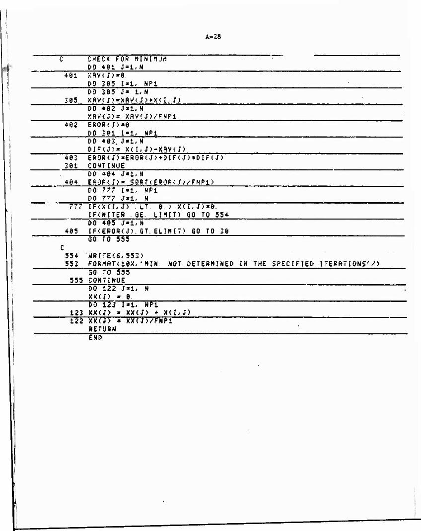
A-28
CHECK: FOR MINIMUM DO 401 J»l,N
401 DO 205
0 NP1
DO 205 J« 1. N 305 XftV<J)»XftV<J)+X<I,J)
DO 402 XflV<J>« • XflVtJVFNPl
402 EROR<J>*0. DO 201 I«l, NP1 DO 402, J»l, N DIFCJ>« X(I,J)-XftV</>
402 EROR<J)«EROR<J>+DIF<J)*DIF<J) 201 CONTINUE
DO 404 J«t,N 404 SROR(J)« SQRT(ERQR(.J.VFMP1)
DO DO
( < < ???
I«l, MP1 N
IFTXCT, J) . IT. 0. ; X'l, J>«8. IF(NITER .66. LIMIT) GO TO 554 DO 405 J*i,N
405 IF<EROR<J). GT. ELIHI7) SO TO 20
554 552
GO TO 555
"WRITER, 552) FQRMflT(10X, 'HIM. NOT DETERMINED IN THE SPECIFIED ITERATIONS'/)
555 GO TO 555 CONTINUE DO 122 XX(J) DO 12f XX(J>
0. l»i, ftTI
XX(J) » X(I, XX(J)/FNP1
122 J) 122 XX(J)
RETURN END
'

APPENDIX B
NUMERICAL CONTROL (NC) MACHINING OF EDM ELECTRODE

APPENDIX B
NUMERICAL CONTROL (NC) MACHINING OF EDM ELECTRODE
This Appendix includes the mathematical derivations used in
developing the computer program for NC machining of the EDM Electrode.
A listing of the computer program is included at the end of this Appendix.
In NC machining, the rotating cutter is moved along some specified
path to generate the desired surface. To move the cutter along this path,
the information on the coordinates of the center of the cutter is fed to the
NC machine via a punched tape. For the present case, APT (Automatically
Programmed Tools) routines are not adequate to give the positions of the
cutter. Thus, special-purpose FORTRAN program DIECUT was written to generate
the NC tape.
Mathematical Basis
The surface to be generated is described by the Equation
H(x,y,Z). tx-h(Z)]2 + [Y-y*n2 -i.o, (B-.U g (c) f <•)
where g(z), f(z), h(z) and k(z) are functions defining die surface, as explained
in Appendix A. Point 0 is the origin of the (x,y,z) cartesian coordinate system,
as seen in Figure B-l. To traverse the surface, a ball-end mill is moved along
radial planes perpendicular to x-y plane and passing through the point 0'. The
Equation of the electrode surface with respect to new coordinate system (X,Y,z)
with origin at point 0' is
m (X + C - h)2 + (Y ♦ D - k)2 _ M
d g f
Cutter Paths
The electrode surface is cut along the radial paths shown in Figure
B-l. The Equation of any such radial plane is
tanö - Y/X , (B-3)
•
>-*e.

B-2
H(x,y,z)=0
(a) «
*♦ -Tool
' Cl(4'Yc'Zc)
FIGURE B-l. NC MACHINING OF THE ELECTRODE TO EDM THE EXTRUSION DIE
(a) Surface of the EDM electrude
(b) Cutter path along radial planes and position of the cutter center C,
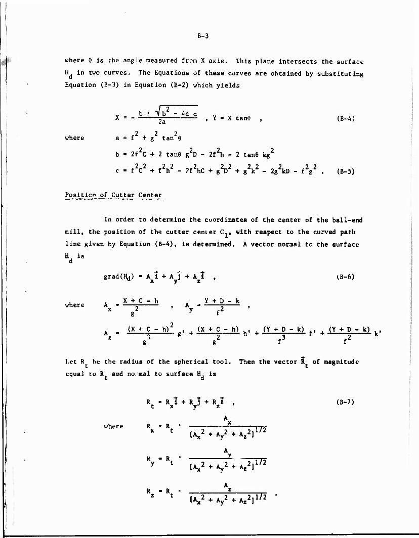
B-3
where 9 is the angle measured from X axis. This plane intersects the surface
H in two curves. The Equations of these curves are obtained by substituting
Equation (B-3) in Equation (B-2) which yields
±V-2 b - 4a c jg . Y » X tanG , (B-4)
2 2 2 where a = f + g tan 6
b - 2f2C + 2 tan6 g2D - 2f2h - 2 tan6 kg2
22 22 2 22 22 5 ? 9 c - fV + fV - 2fZhC + gV + gV - 2g^kD - fg . (B-5)
Position of Cutter Center
In order to determine the coordinates of the center of the ball-end
mill, the position of the cutter center C., with respect to the curved path
line given by Equation (B-4), is determined. A vector normal to the surface
H is d
gradtHj) - A i + A j + A t , tB-6> * y z
X + C - h , Y + D - k where A ■ = , A =* s , * g y f
A . (X + C - h)2 , (X + C - h) , (Y + D - k) , (Y + D - k) , i 3 g 2 n * r3
r r2 * g g f f
let R be the radius of the spherical tool. Then the vector R of magnitude
equal to K and no.mal to surface H. is t a
R «RUR] + R1 , (B-7) t x yJ z '
A where R ' R x "t ,. 2 . . > „ „ ?,I72
IAJJ2 ♦ A 2 ♦ Az2] y
A i ■ i • ^ .
y C [A,2 ♦ Ay2 ♦ A,2]1'2
A R ■ R *
1 ' ^♦V+A,*]1'2 *

B-4
As shown in Figure B-l, the coordinates (Xc, Yc, Zc) of the cutter center are
then given by
Xc = X + Rx (B-8)
Y - Y + R C y
Z ■ z + R c z ,
where R , R , R are determined at point (X, Y, z).
Computer Program
Based on the foregoing derivations, a computer program called
DIECUT wss developed to determine, numerically, the cutter positions. DIECUT
was coded and debugged on a PDP-11 computer. Routines PNCHNC and STORE, which
is written in Assembly Language, are used with DIECUT to generate NC tape in
EIA code. A listing of the programs is attached.
Input to the Program DIECUT
The following information is needed as input to the program DIECUT:
R - Radius of the billet.
AL - Length of the die.
A.B.C.D - Dimensions of the ellipse (Figure B-l).
NDELZ - (NDELZ + 1) is the number of points at which the
cutter position is determined along a radial path line.
DELT ■ Number of divisions in which the surface H. is divided d
radially.
IQUAD - Number of quadrants for which NC tape is to be generated.
IQUAD can be equal to one, two, or four.
In DIECUT, subprogram function F(K,Z) gives the expressions for
functions f(z), g(z), h(z) and k(z). The given listing shows the expressions
for these functions when a cosine form is assumed for them. When other forms
like polynomial or straight-lines are chosen for functions f, g, h and k,
subprogram function F(K,Z) should be accordingly modified.

B-5
Output from the Program DIECUT
A paper tape is obtained as output from the program. The tape has
coordinates of the cutter path punched on it in EIA code. This tape is used
to machine the EDM electrode.
<
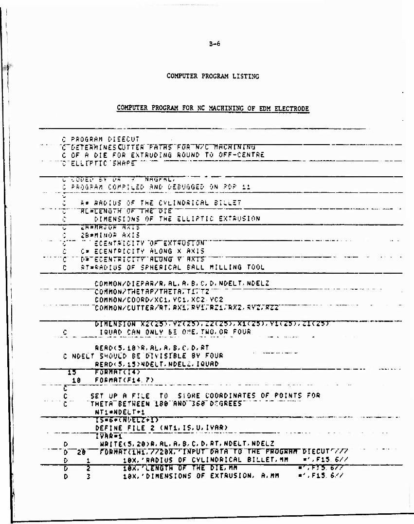
B-6
COMPUTER PROGRAM LISTING
COMPUTER PROGRAM FOR NC MACHINING OF EDM ELECTRODE
j C PROGRAM DIEECUT ~c~~ i> rr E"R'H r N E 5 cu r r ft ft" TBTHF- FcrR-Tr/m rTürrnrnra— C OF fl DIE FOR EXTRUDING ROUND TO OFF-CENTRE
" ~*C"ELLIPTIC SHAPE
C Z v v ft ;■' 3 Y U*- ? N PI tj ? 1L I C PROGRAM COMPILED AND DEBUGGED ON ?DP ii
C R» RADIUS OF THE CYLINDRICAL BILLET "C ITCsrEWBTH-CrF~THE-VrF C DIMENSIONS OF THE ELLIPTIC EXTRUSION t, ZTpTTTfTTTR Hnij ~~ * "~~ ~ C IB»MINOR AXIS
"•; ECENTRICITV -OF~EXT?OSTCTW C C» ECENTRICITY' ALONG X AXIS
"c "~D-~EcrNTTfrc*rTT*rinTN"(r r AKTT C RT»RADIUS OF SPHERICAL BALL MILLING TOOL
COMMON/DIEPAft/R, AL, A, 6, C. D, NDELT, NDELZ CffffHÜ*r7rHETr1P7TrTETftTTr"T?~
COMMON/COORD/XCl.VC1,XC2 VC2 ~CQMMON/CUTTEft/RT, RXX7RSTrBZirSKI, RVTSTSTT "
DIHLN5IÖM X2<27?~vr<25>,Z2<25>,Xl<25>, Viii!5>, JI<25> C I9UADCAN QNLV BE 0"E, TWO. OR FOUR
READ(5. i0>ft, AL. A» B, C. D, »T c NDELT SHOULD BE DIVISTBLE 9V FOUR
READ<5. i3>NDELT.NDEL£. ICUAD ~~n rüTMTrmTj _10 FQBMAT(F14, 7)
C SET UP A FILE TO SIÖKE COORDINATES OF POINTS FOR C" "THETA~BErWE£N 189" AND"~JS0~ DEGREE'S
NTt«NDELT«-i Ig«6WWELZ+l>
_DEFINE FILE 2 (NT1.JS. U» I VAR>_ ~~ * fVAR«l D WRITE<5. 20>R' AL. A. B, C. D. PT. NDELT. NDELZ 0~2"& föRHATaHl.//20X. MMPinrwrrt To THE PROGHR« DlECUTrV77 D i 1BX,'RADIUS OF CVLINDRICAL BILLET. MM ■ ', Ft5. «//
~D 5 lM.'ißMörH oT THE DIE,Hh -f,ri5 577 D 3 tex,'DIMENSIONS OF EXTRUSION, A.MM •'.F15.«//

B-7
0 4 10X, ' " STM'M »TFlS. 5// D 5 10X, ' CMH «',F15. 6/V D 6 1ÖX, ' D, MM «'TFl5_S//' D 7 10X.'BRPIU5 OF SPHESICAL CUTTER, RT, MM ■ • , F15. S// D S " 10X, 'NUMBER OF RADIAL DIVISIONS, ■' ■ TT57? D 9 töX,'NUMBER OF LONGITUDINAL DJ VISIONS,■', 110/>
lt*Z "" ""'" " " 7HETA«0. {1 Z'AL — - ft«5. 1413927*80._0/1S0. Ö_ f2»2"i4t592?*t00r?li0~e" NZ1"NDELZ>1
"- "~RHZ «NDEL7 ' DELZ*AL/ANZ ANT »NDErr ---.- DELT»2. 141592~*2. 0/ANT -jü i j crx «.^ «.*. zrr, iwffp
21 NDELT2«ND£LT/4*i " " tJCTTO" 24
22 MDELT2«NDELT/2*i so~nrz*
22 NDELT2-NDELT/2 uo ru z*
24 CONTINUE D CALL LEADE* ~ c c MOVE TO' rNrrrflL' POSTTTON-
xt(t)«e e vnu-n
Zt<l>a-1. 0 URITE(5,2i7)XiTlJrVl(f57naT CALL PNCHNC <Xt.VI.Zl»-1) XI <1 >••ff*~«T ■>" C Vt<l)«0. 0 ziu>—i. URIT£(5.2t7)Xi(l), Vl(l), Zi(l) C ALL" PNCHNC(XI, vi;ri", t"? —
40 W2WT»!. HDELTg 50 DO 130 J-1.NZ1 1H IHblH. bfc. II. HNU I HE I H. LE. ITTttO IU F0
CftLL DIECOKZ) (jU- T0 r9
60 CALL DIEC02iZ> T0 tmX -CUTVTWCZ7
X1(J>» XC1+BX1 wrm 7ÜTTW71 Zl(J>« AL-<RZW> X2TJ7-XC2T1JXT V2(J)»VC2*RV2
—zr(j>ffffr-(z*BZz> IFCIC. EÖ i)GO TO 60 Z«Z-DELZ GO TO 150
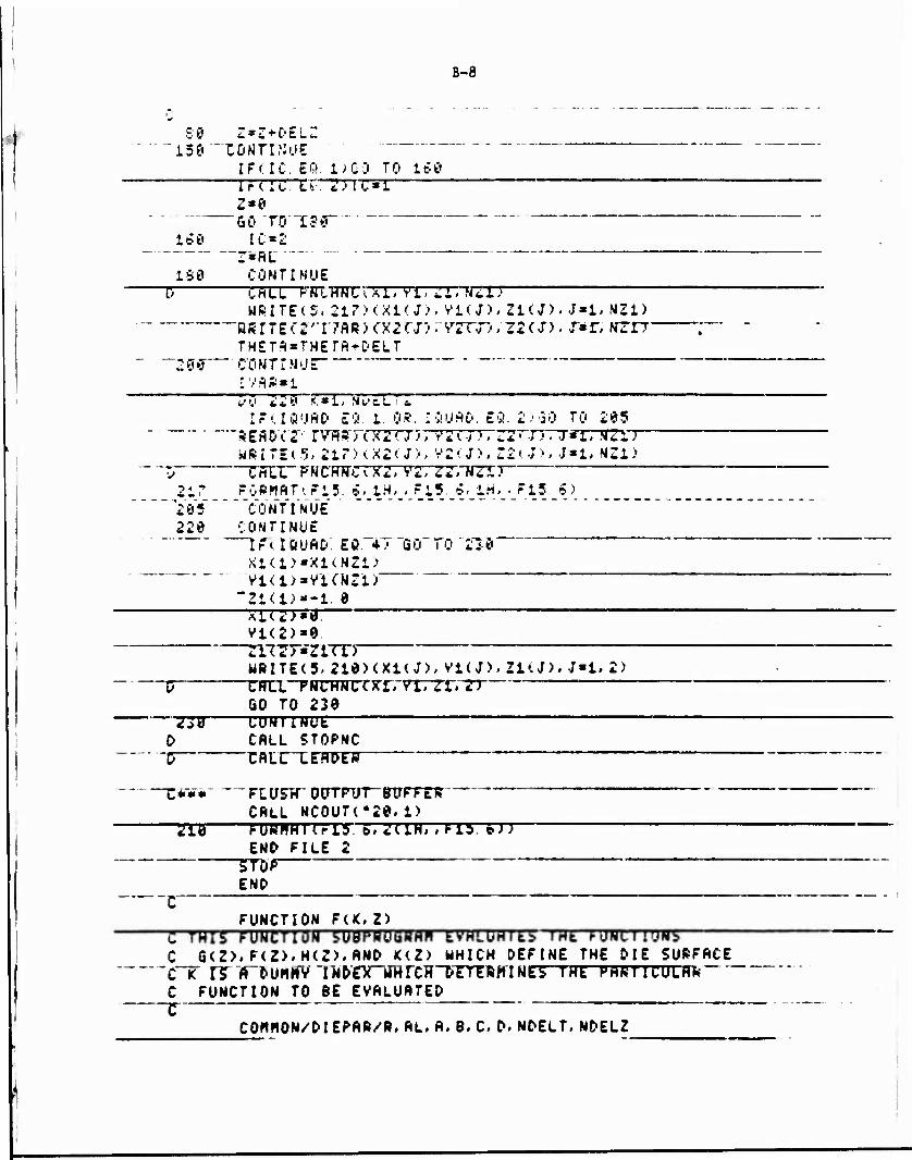
B-8
SO Z^Z + C-ELZ 13e~~"C0NTTWUE
I FC IC. EQ. I) GO TO ISO rnTTTTTTTTC»!
z»o Go TO'188
160 IC*2 I»RL "" ~ ISO CONTINUE
CALL rRrmrcrsTrrrrrmizr? WRITE(S. 217XXKJ), Vi<J># ZKJ). J*l. NZ1)
■HRTTEf 2'T7flR) CXJTJ) 7Y2TJ1 /Z2 CD, W*' N2TT THETA-THETA+DELT
"2 0 ff CO MT r M ü £ rv*R»i
u73 2*TT«r STvcTTZ IrilQ'jAO £9. 1. 0». IÖUAO. EQ. 2><30 TO 205
REfiorr rvrrsrnx2? j5; ?2t.;>; ZT~; ■-. j«i; .vzIT WRITEc?;, 21D<X2U>, Y2<J>, Z2(J>> J«l/ NZl)
CALL FNCHNCiXZ, Y2, Z2\ NZi7 217 FORMAT', F13. £> 1H. - ?l5. 5< 1H. . F15 <S >
Ye 5" coVf IWB 220 CONTINUE
IFTIÖUAD'. EÖ. *T GO TO'210 X1(1>«X1(NZ1> VKl>»VUNZi>
"Zl(U«'t. 0 _rTZ7_T
Vl<2>«9 zu2> «riTrr URITE<5. 210XXKJ), V1(J), ZKJ), J*l, 2)
—p CRTLTNCHNC <xTrvrrzrm GO TO 230
—TJB CONIINUL D CALL STOPNC
-j? r RITTETOCT
X*V» FLUSH" OOTRTT-ffOrFTR CALL NC0UTC20. 1)
TIB ruwrnnrrr PTTTTHTTTO: ETJ END FILE 2
?TOP END
FUNCTION FtK»Z) C THIS EDUCTION" SUBPBOBBAPI EYTOHTES TTfl f-UNUIUH!» C G<Z>.F<Z>.H<Z>.AND K(Z) WHICH DEFINE THE DIE SURFACE C~T rr"A~DUHKV"lN&rx_iIHrCHT'TrTRHINE5 THE PARTICULAR"" C FUNCTION TO BE EVALUATED T—
COMMON/'DIEPAR/B.AL.A.B.C D.NDELT,NDELZ
>

B-9
GO TO~Tr0 > i.*i> 2W> *tf • i>0• 531 "tf! S►.' 5. K.
C -£-■---■ ""FUNCTION G<Z> ""
13 F«CR+A>/2. 0 + <<R-ft)/2. 0>*COS<2. i4l5927*2/ftL) GO Tö 90
C ™C FUNCTION rU.1
20 F*(R + B)/2. 0*(f.»-e>/2. 0)*CQSC<. t4t592?*Z/AL> "~ GO TO 90
C C FUNCTION H<2>"
30 F»C/2. 0+<C/2. 0>*COS<2.14l5927*<fiL-Z)/ftL) . UJJ Tö 95
C
40 F*D/2. 0*<E>/2. 9>*C0S<3. i4139£7*<rlL-Z;V*L) GO TO '90"
~Z PütiCTIÖN V (l! 50 F_"'>3- t4jL_5_927YfiU*<_S_-ft>««SIN<.2. 1415927»Z/HL>/2. 0 _. GCffO 90 "
C ~r FUNTTT^N_rTr5 ~
50 F «c-i. 14l39£7/AL)*(S-e>*SIN<. 2. 14l5927*2/FiL^',2. 0 &ü Tö w
C_ T~ F'UNCTTüN H*(':>
70 F »<3. 14l5927/fiL>*<C/'2 8>»SIN<3. 1415927»<flL-Z>/*L> "Gö~ry 90
c ~C FUNCTION K' (&
66 F »<3. 1415927/ftL>»<E/'2. 8>»SINCi:. 1415927«<RL-Z>/RL> " "GÖ~TO 98 " " ~
C 99 RETURN ■■-----
_SND SUBROUTINE DTECÖt<z7~~~ ~
c ___ C"THrs~ SUBROUTINE" SOLVES F^TR—X~HWü v cuuKPiNHibb u»» H HUINI1
C ON TOOL PATH FOR GIVEN Z COORDINATE MHEN THETft DOES NOT C LIE 6ETWCEN tfBHHO 18»' DEGRETS
COHHON/DlEPSR.'S», RL, R* B.C. C, N&ELT-NDELZ cowww7TBrnrF7TRTnr ii, rz COHHON/COORD/XCl. VC1, XC2> VC2
—■COHMOTT/CUTTER'TRr;RXTrsYirRZrrffXi:, HV'i, KZÜ FQ«F(l,Z)
—TV* rxznn FH-F<J, Z>
FTWFTW7D SQ-FG»*2
"5F«FF**2 SH«FH**2 sr-Fic**2 T ■SIN<THETR)/C05<rHETA)

B-10
rfü-br+tli*! **2. « 60»2 B*SF*C* 2*f*SG*D - 2. 0*SF*FH -2. ti*T*= S'3 +:FK C0*SF*O*2. 0 + SF*SH-2. *5F*FH*C~*' " SfffcTTWTTtf*
1 5G*SK>2. *SG*D*FK -SF*SG DU» SQRT?BP**2 -4. P*flO*CO>
IF(THETA. GE. -1. 6E-5. AND. THETfl. LE. TDGO TO 1* XCi»f-3ü-DÜ>A2. 3**TTCn
XC2*< -BO+DO>/< A. 0*AO>
lö XCi*OB0+D0>/<2. 0*flü> KT2~»T-F(PDJ77C2 B*flOT" £8 VCl»XCl*T VC2,XC2lll
RETURN ETiD"
SUBROUTINE DIECÖ2<2>
C THIS SUBROUTINE SOLVES FOR X AND V COORD I NATES OF •: A POINT o^ TOOL PATH FUN üIV&N : cuu-uMMhit STFO— C THETft LIES BETWEEN 36 TO l&O DEGREES C
COMMON/DIEPAR/R, AL, A/ B, C, D, NDELT, NDELi
CCMMONXCOÜRD/XC1, YCt, XC2, VC2 L'uwwuM/turr6iJ/rfi, axi, RTT ran BA^ SVI, STS FG«F<i,Z)
- FF5FT?; n FH«FO,Z>
"FT*F(4, Z7 SG«FG**2 5F*TFT*2 SH«,"H**2
~ 5IC«Tr»'*,1 T2»2. i>U3927/2. 0-THETfi
TO"» r, JRTST/CCTSTTTJ fl0«S6*SF*T0»*2. 0 B0»2. g»T0»O5F-Z. U»TP«FH4^ +2 UWbW. H«H*bta C0«SF*C**2. 0*S.r*SH-2. «C*FH*£F«-SG*D**2. 0* TIT'SK-2". ~0*D»FK*5"G-TF*TG D0«S08T(B0«*2-41 0*AO*CO>
TÜ1 • t - BU*W> 7T7~0^ffCO ve2»<-B0-P0>/t2. »ftO> XCl»VCi*TO " XC2«VC2»T0 RTTUJfN END TUFKournir TxmrnfTzr
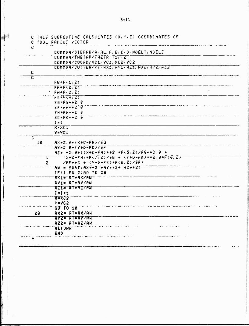
i
B-ll
C THIS SUBROUTINE CALCULATES <X. V, Z> COORC'l MftTES OF C TOOL RADIUS VECTOR C "
COMHON/DIEPAR/R, AL, A, B, C» D, NDELT, NOELZ " COrtMON/THETftP/THETA, TITT2
CGttMON/COOSD/XCl,VCi.XC2, VC2 COHHONTOJI itH/'WI, HXi» WVi, PZT3 WA<!, .A'«!, STZ2" C
FG*F<1,Z) —FF«FT2rZT~ ' FH«F(S,Z> —nunnrr, T>
Sfi*FGi**2. #
SH»FH**2. 9
I»i X-XC1
v»vci
IS AX»2. 0«<X+C-FH>/SG RY*2r0*TYVp-FTC)YST
AZ* -2.0*<<X+C-FH>**2 *F<5,Z>/FG**2. 9 * T T7*Z=r^rWT77TT7T^ * <V-H>-riU**«!. 7*FTF7T3
2 /FF**3 ♦ <V+D-PIO*P<8* Z)/SF>
IF(I. EC. 2)60 TO 20 ffXI«- RT*fl5T/AH""
RV1« RT*AV/flU R21» RTtnZ/HU
I«I*1 ysxC2 ~*~ V»VC2 6cr TO te
20 RX2» RT«flX/AU RV2- RT*flV/flU
RZ2» RT**Z/AU RETURN " END
'
CHAPTER III
"COMPUTER-AIDED DESIGN AND MANUFACTURING (CAD/CAM) OF STREAMLINED DIES FOR LUBRICATED EXTRUSION OF SIMPLE STRUCTURAL SHAPES"

TABLE OF CONTENTS
Page
INTRODUCTION 3-1
EXTRUSION OF SIMPLE SHAPES 3-2
Definition of the Die Geometry 3-4 Calculation of Extrusion Load and Die Pressure 3-8 Mt :jfacturing of the Extrusion Dies 3-15 Analysis of the Shape-Extrusion Process by the Computer Program
"SHAPE" 3-18
EXTRUSION TRIALS 3-20
Outline of Extrusion Trials 3-20 Results of Extrusion Trials 3-28 Evaluation of Results 3-31 Conclusions 3-36
SUMMARY 3-37
REFERENCES 3-39
APPENDIX A: DETERMINATION OF THE DIE GEOMETRY
APPENDIX B: CALCULATION OF EXTRUSION LOAD AND DIE PRESSURE DISTRIBUTION
APPENDIX C: NUMERICAL CONTROL (NC) MACHINING OF THE EDM ELECTRODE
APPENDIX D: DESCRIPTIONS OF GENERAL-PURPOSE COMPUTER PROGRAMS
APPENDIX E: SHAPE - A SYSTEM OF PROGRAMS TO ANALYZE THE SHAPE- EXTRUSION PROCESS
APPENDIX F: MANUFACTURE OF EXTRUSION DIES
LIST OF ILLUSTRATIONS
Figure No.
3-1. Schematic of a Streamlined Die for Extruding a "T" Shape . . 3-3
3-2. Construction of a Streamlined Die Surface in Extrusion of a Rectangular Shape 3-6
3-3. Deter lination of the Position of the Neutral Axis in "T" and •V Shape» 3-7
3-4. A Streamline Die Surface for Extruding a Rectangular Shape from a Circular Billet 3-9
i

LIST OF ILLUSTRATIONS (Continued)
Figure No. Page
3-5. A Streamline Die Surface for Extruding a Trapezoidal Shape from a Circular Billet 3-10
3-6. A Streamline Die Surface for Extruding a "T" Shape from a Circular Billet 3-11
3-7. Mean Extrusion Pressure Versus Die Length Calculated for Extruding a Rectangular Shape from a Round Billet 3-14
3-8. Mean Die Pressure Distribution Along the Die Surface in the Direction of Extrusion for the Process Conditions Specified
in Table 1 3-17
3-9. Cutter Path in NC Machining of EDM Electrode 3-19
3-10. Schematic Illustration of the Air Force Materials Laboratory's Extrusion Press 3-22
3-11. Rectangular and Round Shapes Extruded in the Trials 3-24
3-12. Dies Used for Extrusion Trials 3-27
3-13. Illustratior of the Die-Container Arrangement and the Die Configuration Causing Lubrication Breakdown 3-29
3-14. Comparison of Actual Metal Flow with That Predicted from Theoretical Model 3-33
LIST OF TAB? g,S
Table No.
3-1. Input and Output Information from the Computer Program "SHAPE" on Lead and Die Pressure Distribution 3-16
3-2. Summary of Process Conditions Investigated in the Extrusion Trials 3-21
3-3. Billets Used in Extrusion Trials 3-25
3-4. Results of Extrusion Trials Conducted at AFML 3-30
3-5. Comparison of Predicted and Measured Extrusion Pressures for the First Set of Trials 3-35
3-6. Comparison of Predicted and Measured Extrusion Pressures for Second Set of Trials i-35
ii

CHAPTER III
CAD/CAM OF STREAMLINED DIES FOR LUBRICATED EXTRUSION OF SIMPLE STRUCTURAL SHAPES
ABSTRACT
This chapter describes the work conducted towards applying CAD/LAM
techniques to the extrusion of simple shapes, such as L's, T's, rectangles,
and triangles. A numerical technique is described for defining the surface
of a "streamlined" die in lubricated extrusion. A theoretical analysis is
developed for calculating the mean-extrusion pressure and the mean-pressure
distribution on the die surface for the lubricated, as well as for the non-
lubricated shape-extrusion processes. To manufacture the "streamlined" dies
by Electro-Discharge Machining (EDM), the theoretical basis for Numerical
Control (NC) machining of the EDM electrode was outlined. Based on the
aforementioned analyses, a system of computer programs called "SHAPE" was
developed. SHAPE allows determination of (a) optimal length and shape of the
die in lubricated extrusion, (b) shear-zone configuration in nonlubricated
extrusion, (c) extrusion load and die-pressure distribution, and (d) cutter
paths in NC machining of EDM electrodes. SHAPE can be used in batch, as
well as in interactive mode.
A limited number of trials were conducted to evaluate the CAD/CAM
techniques developed in this program. For this purpose, round billets from
copper 110, aluminum 6063, and aluminum 7075, were extruded using the same
extrusion ratio through three types of dies: (1) a streamlined die from
round to rectangular, designed and manufactured by CAD/CAM techniques, (2)
a flat-faced die from round to rectangular, and (3) a streamlined die from
round to round. Results on extrusion loads and metal flow, obtained from
the trials, indicated good agreement between predicted and measured values.
INTRODUCTION
In conventional extrusion of high-strength aluminum alloys, 2000
and 7000 series, flat-faced dies are used. This results in interna^shearing
and significant temperature increases within the deforming material. Conse-

3-2
quently, the extrusion must be carried at a sufficiently low speed to avoid * (1 2)
hot shortness in the product.
Lubricated extrusion of hard-aluminum allcvs is expected to in-
crease production rates and to lower the required nress capacity to extrude
a given product at a predetermined extrusion ratio. In lubricated extrusion
of relatively complex shapes, such as U, L, T, I, and others, it is required
to use "streamlined" dies which provide a smooth metal flow from the circular
container, or billet, to the shaped-die exit. The effective design of such a (3"1
die must ensure a smooth metal flow and consistent lubrication. ' One of
the primary objectives of the present program is to develop cost-effective
computer-aided techniques for designing and manufacturing streamlined dies
so that lubricated extrusion can become a practical manufacturing process.
The other objective is to apply advanced computer-aided techniques to optimize
the conventional lubricated and nonlubricated extrusion processes.
EXTRUSION OF SIMPLE SHAPES
The design of a "streamlined" die for extruding a "T" shape from a
round billet is schematically illustrated in Figure 3-1. The geometry of this
die and the variables of the extrusion process should be optimized to (a) give
a defect-free extrusion requiring minimum post-extrusion operations (twisting
and straightening), (b) requlie minimum load and energy, and (c) yield maximum
throughput at minimum cost.
The process variables to be selected are the speed of the operation,
the die geometry, the temperatures of the material and the die, and the
frictional conditions at the container-die interface. There is no systematic
engineering method which can be used for optimizing the shape-extrusion
process. The trial-and-error approach, combined with past experiences, are
commonly used in today's industrial practice to obtain satisfactory die and
process designs. In the present program, a systematic approach, which utilizes
computer-aided techniques, is presented to optimize the lubricated as well as
the nonlubricated extrusion processes. The analysis of the mechanics of metal
flow, and the calculation of the extrusion load and the die pressures
represent the basis for the optimal process design. As a first stap in the
designing process, the die geometry must be defined. A computerized numerical

3-3
k
10 I
k0
If) I
m
e o
T-i w 3 u 4-1
3
wJ
£
H
•H
a £
o w c
c o
u «
s o
o
(/> o CO
o u u
o
a u
'

3-4
technique is used for this purpose.
Definition of the Die Geometry
In nonlubricated extrusion of shapes through flat-faced dies, the
deforming material shears internally during the initial stages and forms
so-called "dead zones" on the flat face of the die. The formation of dead,
or nonmoving zones, generates a new "pseudo-die surface" for subsequent flow
of the material during the extrusion process. To analyze the stea&y-state
extrusion process, the shape of the dead zones must be predicted, based on
the principle that the material deforms such that the rate of energv dissi- (4)
pation is minimum. In analyzing the conventional extrusion of round
shapes, the shape of the dead zone can be predicted bv calculating the rate
of energy dissipation in extrusion through an arbitrarily-shaped die, or
through dies of different configurations. The die which requires the
minimum extrusion pressure yields the shape of the shear surface. A similar
procedure can also be used for predicting the shape of the shear surface in
extrusion of nonsymmetric shapes. However, a surface which provides a
smooth transition fron the initial round billet to the final nonsymmetric
shape is too complex to be defined analytically. Therefore, in the present
study, a numerical procedure is used for defining the die geometry.
In lubricated extrusion, the die should provide a smooth transition
from the circular billet to the final extruded shape. In addition, the die
surface should be such that the material undergoes minimum redundant deforma-
tion and also exits from the die without bending or twisting. To select the
shape of the optimal die, metal flow through lies of different shapes must be
analyzed. The optimal die geometry can then be determined by selecting the
die configuration which gives the minimum rate of energy dissipation during
extrusion. This approach requires that, as a first step, the surface of the
streamlined die be defined in a general and arbitrary manner. Again, for
structural shapes like T, L, U, and others. It Is not possible to describe
analytically a die surface which provides smooth transition from a round
billet to the desired final shape. Thus, a numerical approach for defining
the die surface is necessary for lubricated extrusion, as is the case in non-
lubricated extrusion.

3-5
Details of the numerical approach, used to determine the die surface,
are given in Appendix A. Here, only the procedure is summarized. A primary
requirement in the design of the shape-extrusion process is that the extruded
material should exit from the die without twisting or bending. This require-
ment is satisfied if the die chape is such that the extruded material st the
die exit has, across its cross section, a uniform velocity in axial direction.
Thus, each segment of the original cross section must undergo equal area
redin f Ion. The initially circular cross section of the billet is divided into
a number of sectors, as shown in FiRure 3-2. Starting from a plane of symmetry,
the final cross section is divided Into the same number of segments. This is
done while keeping the extrusion ratios (area of a sector in the billet/area
of the corresponding segment in the product) equal to the overall extrusion
ratio. Thus,
A Area 012 Area 023 Area 045 _o n n Area 01'2' " Area 02'3' " Area 04'5' " Af * K '
where A is the billet cross-sectional area and A, is the cross-sectional area o f of the rectangular product. According to this construction, the material
points at positions 1, 2, 3, 4, and 5 on the boundary B of the initial cross
section move during extrusion to positions 1', 2', 3', 4', and 5*, respectively,
on the boundary B of the final cross section. Thus, the initial and final
positions of the material path lines along the die surface are determined. The
path followed by any material point between the initial and final positions is
not known. Therefore, arbitrary curves, are fitted between corresponding points
of the boundaries B and Br. These curves define numerically a general die o r surface, any portion of which can be changed by ad lusting the curves fitted in
that portion of the surface.
In Figure 3-2, due to symmetry of the extrusion shape, rectanRular
in this case, no metal flow occurs perpendicular to the extrusion axis 0-0'.
Thus, the axis 0-0' is called "neutral axis". For shapes like T and A, which
have only one plane of aymnetrv, the position of the neutral axis is determined
by a procedure described in Appendix A and summarized here. As shown in
Figure 3-3a, the position x of plane x - x is determined such that the ratio
of the area 0'ab to the area 012 is equal to the overall area reduction (A /A.)
In extruding fi-"» round to "T" shape. Thus, b-2 becomes .* material path line.

3-b
Sectors
Billet
5*
—""Ir^L //
n // . // ni
t f 1 1 '
1 A< 3 r
o'
^
0
\ -
Bf
Product J V-Neul rol oxis /
Moteriol path along die surface
FIGURE 3-2. CONSTRUCTION OF A STREAMLINED DIE SURFACE IN EXTRUSION OF A RECTANGULAR SHAPE

3-7
x»xr
Material path lines
-Plane of symmetry
Product
(a) Extrusion of o "T" shape
Billet
Product
A »'»c
(b) Extrusion of an "L" shope
FIGURE 3-3. DETERMINATION OF THE POSITION OP THF NEUTRAL AXIS IN T ANO 'V SHAPES

3-8
The Intersection of the plane x - x and the plane of symmetry, v - 0, gives
the position of the neutral axis.
For shapes which do not have any plane of symmetry, like the "L"
shown in Figure 3-3b, the position of the neutral axis is determined as
follows. The position of plane x - x is defined such that the ratio of area
ABDA to area abda is equal to the overall area reduction. In a similar way,
the position of plane y ■ y is obtained when the ratio of area ABCA to area
abca is equal to the overall extrusion ratio. Intersection of these two planes,
x • x and y ■ y , gives the neutral axis 00'.
Once the neutral axis is determined, the initial cross section is
divided into a number of sectors starting from the neutral axis at point 0.
As before, the final cross section is divided into equal number of triangular
segments starting from point 0', while maintaining the area ratios between
sectors and corresponding segments equal to the overall extrusion ratio.
Based on the procedure outlined above, a computer program was
developed, This program forms a part of the system of programs called "SHAPE",
which can be run in interactive as well as in batch mode. In interactive mode,
a plot showing billet shape, product shape, neutral axis, material path lines
and die cross sections is drawn on CRT (Cathode Ray Tube). During the various
stages of plotting, the designer can Interact with the program to change, if
necessary, the position of the extruded shape with respect to the billet center,
and the position of the neutral axis. Figures 3-4 through 3-6 show the die
surfaces obtained by the above numerical procedures. The plots were obtained
as hard copies of CRT screen displays. Due to the symmetry, only upper halves
oi the die surfaces are plotted.
Calculation of Extrusion Load and Die Pressure
To optimize the extrusion process wit regard to load and energy
requirements, an analysis was developed for calcul ting the load and die
pressure distribution. The knowledge of the total extrusion load and of Its
components would also help the designer in selecting the extrusion of ad-ouate
capacity and in evaluating the overall efficiency of the extrusion process.
The mean-die pressure distribution along the die surface Is needed to predict
the stresses developed in the die during the extrusion process. Thus, this
information should help the designer in making appropriate selection of die
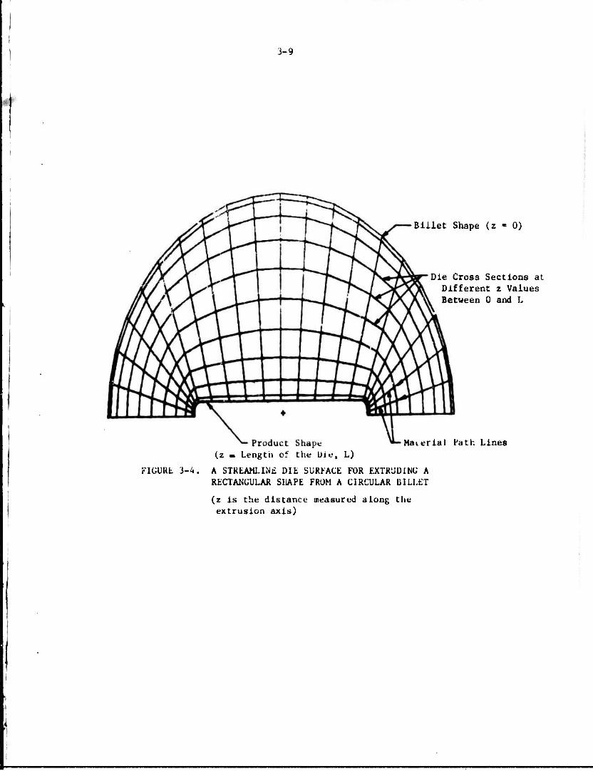
3-9
Billet Shape (z - 0)
Die Cross Sections at Different z Values Between 0 and L
Product Shape (z m Length of the Die, L)
Material Path Lines
FIÜURL 3-4. A STREAMLINE DIE SURFACE FOR EXTRUDING A RECTANGULAR SHAPE FROM A CIRCULAR BILLET
(z is the distance measured along the extrusion axis)

3-10
Billet Shape (z = 0)
Die Cross Sections r Different z Values Between 0 and I.
Product Shape (z - Lenpth of the Die, L)
Material Path Lines
FIGURE 3-5. A STR'- ML1NE DIE SURFACE FOR EXTRUDING A TRAPEZOIDAL SHAPE FRJM A CIRCULAR BILLET
(z is the distance measured along the extrusion axis)
'

3-11
Product Shape (z - Length of the Die)
Billet Shape (z - 0)
Die Cross Sections at Different z Values Between 0 and L
Material Path Lines
FIGURE 3-b. A STREAMLINE ÜIL SURFACE K)R EXTRUDING A "T" SHAPE FROM A CIRCULAR BILLET
(z is the Jibtaace along the extrusion axis)

3-12
material and In avoiding unnecessary premature failure of the dies.
A simple method which is basically an extension of the so-called
Siebel's method is used to calculate:
(1) Total extrusion load and the various components
that make up this load
(2) Distribution of mean-die pressure along the die
surface in axial direction.
The total extrusion pressure P is given as the sum of its components by
p " ?c + ?4A + p K + Pirj + ?« • (3-2) avg fc id sh fd fl
where Pf • component of pressure due to friction in container
P.. ■ component of pressure due to internal plastic
deformation for area reduction
P , ■ component of pressure due to shear deformation at sn
entrance and exit of the die
P.. ■ component of pressure due to friction at die surface ra
?f. - component of pressure due to friction at die land.
The various pressure components are determined using the basic theory of
plasticity. The pressures due to friction at the container and the die
surfaces are determined by assuming the interfacial friction stress (i) to
be given by:
T - m — . (1-3)
o is the flow stress of the material at the interface and m is the friction
shear factor for a particular interface, m is taken to be constant for given
conditions of lubrication, billet material, temperature, and die material.
The details of the analysis are given in Appendix B. From tl«- total extrusion
pressure, the total extrusion load is determined by the relation:
n 2 Total Extrusion Load - 7 D P , (3-4)
4 o avg
where D is the initial diameter of the billet, o
The die pressure distribution is calculated using the condition that
the mean-extrusion pressure at any cross section of the billet can be approxi-
mated by the pressure required to extrude the portion of billet between that

3-13
section and the die exit. Knowing this pressure, the mean pressure acting
on the die at any cross section can be determined from the plasticity condition,
as described in Appendix B.
The load and the pressure distribution are obtained as function of the
process variables like initial billet diameter, initial billet length, speed of
the extrusion press, final extrusion shape, area reduction, type of die (flat
face or streamlined), friction at container and die surfaces, temperauure, and
flow properties of the material being extruded. For given values of these
process variables, the extrusion load is calculated numerically. Special
computer programs, developed for this purpose, form a part of system of programs
"SHAPE".
For lubricated extrusion, the streamlined die surface is defined
according to the procedure discussed earlier and then the load is calculated.
In case an optimal die length (or height, is to be determined, the extrusion
pressure is calculated for different die lengths. In batch mode, the die
length which requires minimum extrusion pressure is selected. In interactive
node, the extrusion pressure is plotted on CRT as a function of the die
length. Also, the numerical values of pressure and die length are printed.
The designer can use his Judgment to select the optimal die length, which he
then enters through the keyboard for further load calculation. Figure 3-7
shows, as an example, a plot of extrusion pressure versus the die length,
obtained as a hard copy of the CRT screen display. The reason for selecting
a die length which may not require minimum pressure is that the minimum
pressure is not the only consideration in selecting an optimal length. Other
factors, such as keeping the die length short to have small discard and re-
ducing the cost of manufacturing the dies, must also be considered. In the
Interactive mode, the designer can select the die length based on his judgment
of the relative importance of all these factors.
In nonlubricated extrusion through flat-faced dies, the material
shears Internally and forms a dead zone at the entrance face of the die during
initial stages of the extrusion process. A new "pseudo-die surface" is thus
created for subsequent extrusion. To calculate the extrusion load, it is
assumed that the general configuration of the si,«ar surface Is the savne as
that of the optimal die for lubricated extrusion, with the difference being
that the determination of the "pseudo-die" length is based on the maximum
shear factor (m.) at the "pseudo-die" surface. The interative procedure, a
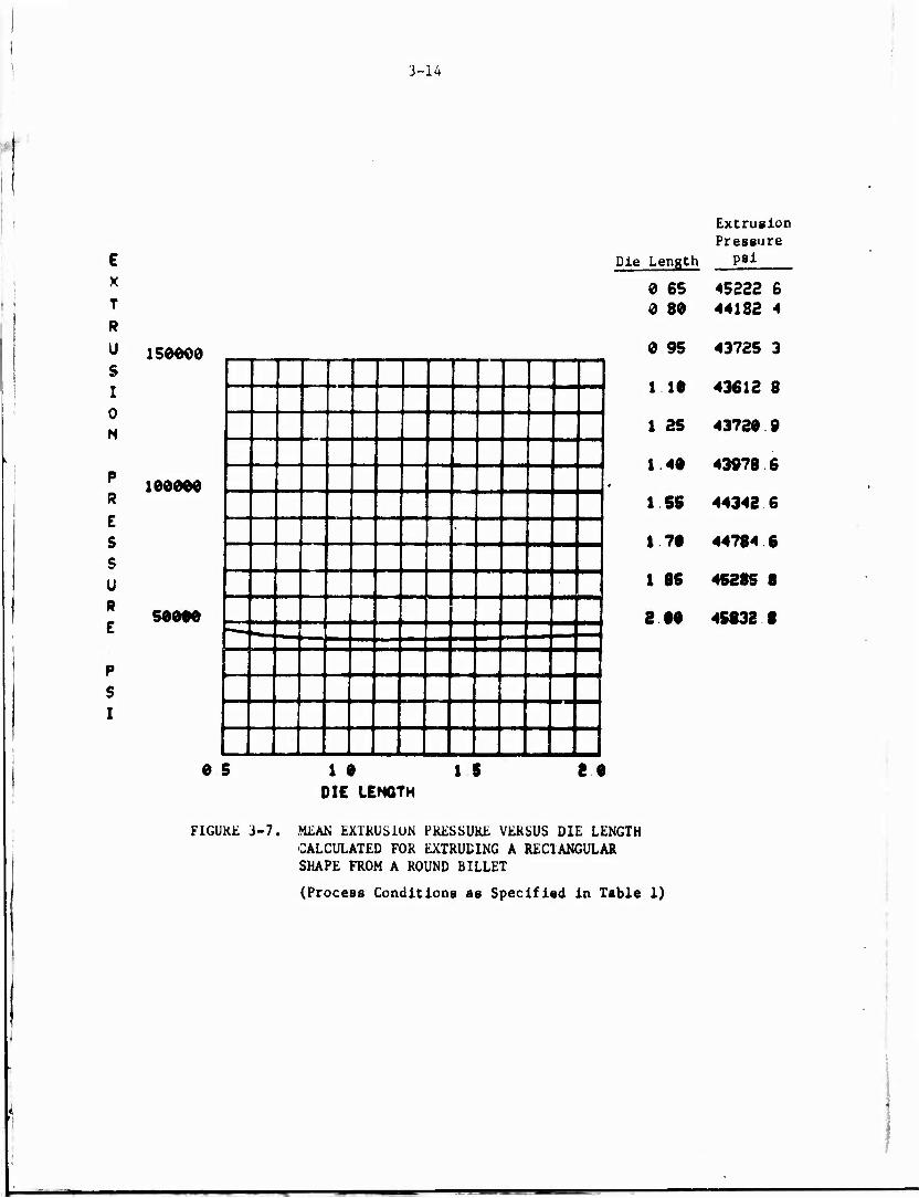
3-14
E x T
R
Ü
S I 0 N
P R
E S s u R
E
P S
I
150600
100000
50000
'
1
Extrusion Pressure
Die Length psi
0 65 45222 6 0 80 44182 4
0 95 43725 3
1 10 43612 8
1 25 43720 9
1 40 43978 6
1 55 44342 6
1 70 44784 6
1 85 45285 8
2 00 45832 8
0 5 1 0 DIE LENGTH
15 2 0
FIGURE 3-7. MEAN EXTRUSION PRESSURE VERSUS DIE LENGTH CALCULATED FOR EXTRUDING A RECTANGULAR SHAPE FROM A ROUND BILLET
(Process Conditions as Specified in Table 1)
3-15
discussed earlier, is used to calculate the optimal die length for m, - 1 and d
this length is then used for calculating the extrusion load for nonlubricated
extrusion process.
As an illustration, Table 3-1 shows the input and output obtained
from the computer program "SHAPE" for a specific case. As input, the material
code (IMATER) specifies the material to be extruded and die-curve code (NCURVE)
specifies the type of curve fitted between initial and final positions of a
material path line, as discussed previously. In interactive mode, the mean
die pressure distribution along the axial direction, z, is plotted on CRT.
A hard copy of the CRT display is shown in Figure 3-8.
Manufacturing of the Extrusion Dies
For lubricated extrusion, the streamlined dies have complex surfaces
as shown in Figure 3-4. Since conventional methods like copv turning or milling
cannot be used, the only practical and economical method of manufacturing such
dies is the Electro-Discharge Machining (EDM). In this process, the appropriate
surface is machined on an electrode made of graphite or copper. This electrode
is then used to EDM the rough-machined die block to generate the desired sur-
face .
In our case, the die surface is defined as an array of points in a
three-dimensional space, as shown in Figure 3-4 through 3-6. Standard APT
(Automatically Programmed Tools) and other standard systems for NC machining
cannot be readily used to generate the necessary tape for machining of the
die surface. Therefore, a special procedure was developed for NC machining of
the EDM electrodes. The details, including the theoretical basis of the pro-
cedure, are explained in Appendix C. A short description is included here.
For machining the surface by NC, the paths of the cutting tool as
it machines the surface should be determined. If a ball-end mill is used,
the position of the center of the spherical portion, with respect to any given
point on the surface, can be determined by constructing a vector normal to the
surface at that given point. In our case, the normal vector is calculated from
the cross product of two vectors; one tangent to the surface along the material
path line, and the other tangent to the cross-sectional boundary. fo*«p tool
of given radius, the coordinates of the cutter paths are determined as the tool
moves, in a predetermined manner, o\;er the arrav of points defining the die
surface.
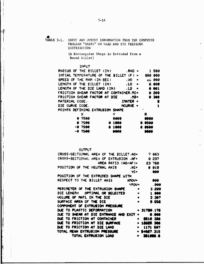
3-1*
TABLE 3-1. INPUT AND OUTPUT INFORMATION FROM THE COMPUTER PROGRAM "SHAPE" ON LOAD AND DIE PRESSURE DISTRIBUTION
(A Rectangular Shape is Extruded from a Round Billet)
INPUT RADIUS OF THE BILLET (IN) .RAD INTIAL TEHPEKATURE OF THE BILLET (F) SPEED OF THE RAM (IN SEC) .UO LENGTH OF THE BILLET (IN) ,LO LENGTH OF THE DIE LAND (IN) .LD FRICTION SHEAR FACTOR AT CONTAINER.MC FRICTION SHEAR FACTOR AT DIE ,PID MATERIAL CODE. DIE CURVE CODE.
WATER NCURUE
POINTS DEFINING EXTRUSION SHAPE X
e 7500 e 7500
-0 7S00 -0 7S00
V 0000
0 1000 0 1000
1 500 800 000
co 000 6 000 0 061 0 300 0 300
I 1
ACAA
OUTPUT CROSS-SECTIONAL AREA OF THE BILLET.AO CROSS-SECTIONAL HRE* OF EXTRUSION .AF
AREA RATIO (AO/AF) POSITION OF THE NEUTRAL AXIS .XC
VC POSITION OF THE EXTRUDED SHAPE UITM RESPECT TO THE BILLET AXIS XNOU
vnou PERIMETER OF THE EXTRUSION SHAPE DIE LENGTH OPTIMAL OR SELECTED UOLUME OF MATL IN THE DIE SURFACE AREA OF THE DIE COMPONENT OF EXTRUSION PRESSURE DUE TO PLASTIC DEFORMATION DUE TO SHEAR AT DIE ENTRANCE AND EXIT DUE TO FRICTION AT CONTAINER DUE TO FRICTION AT DIE SURFACE DUE TO FRICTION AT DIE LAND TOTAL MEAN EXTRUSION PRESSURE
TOTAL EXTRUSION LOAD
■ 7 069 0 297
23 760 0 019
000
• 000 U- 000
3 299 1 000 3 307 9 550
• 31710 170 0 000
• »10 320 • 12029 304 • 1171 S07 • §4027 315 • 391990 •

3-17
Ui
i/ianoM »•• r- ru ru -• ©
o
9O6O96O0OSSUI N9^nintU)U)MOCnS(B
OO<S9SO990>4H
■ ' ■ ■ ' - —■ ■ -■■ 'T"~~
7 ^
7 - /
i " X '
to 1<5 o M
UI H U M < p 2 o 3 U VJ
CO w w M W Q O
o jj a! 35 cu H
W O 33 Z H
<9
Z o z H O f-l M p c/1
» M 5
®
DISTR
OF EXT
E 1
U> 3 O <C N
9 to M H v> W H •-•
5 E
PRE
DIREC
ED IK
▼ r —1 M
© o »4
Q y t*t 35 >-<
V» Z H U < U] u .'. a. 5. M C/1 5
»- fU X
UI • e»
3 © 3
1 I« fu
Q •- u 0. a u ui <y> _j u: UJ
3-18
Based on the above procedure, special-purpose FORTRAN programs are
written. These programs also form a part of the system of programs called
"SHAPE". In SHAPE, special routines are included to check for undercutting
or gouging by the cutter.
In interactive mode, the calculation of the cutter positions and the
plotting of these positions on CRT are done simultaneously. If undercutting
is detected, the program stops momentarily and a warning is displayed on the
CRT screen. The designer has then the option of reducing the size of the tool,
or proceeding with the program, or stopping it. Figure 3-9 shows an example
plot of cutter paths for machining an EDM electrode for a round-to-rectangle
extrusion die.
Analysis of the Shape-Extrusion Process by the Computer Program "SHAPE"
As stated earlier, the procedure of defining the die surface, the
analysis to calculate the extrusion load and pressures, and the procedure for
NC machining of the EDM electrode for the die nre Incorporated in a set of
computer programs called "SHAPE", which can be used in batch or interactive
mode. Thus, SHAPE analyzes the extrusion of simple shapes and prepares the
necessary output for optimal design of the extrusion process. The following
arc the capabilities and salient features of SHAPE:
• Determination of the optimal length and the die
configuration in lubricated extrusion
• Calculation of the shape of the .«hear zone in
nonlubricated extrusion of simple shapes
• Calculation of the extrusion load and the mean-die
pressure distribution
• Calculation of other pertinent information, such as
area reduction in extrusion, the perimeter of the
extruded shape, and the» flow stress of the extruded
material
• Calculation of the cutter paths for NC machining of
the EDM electrode for manufacturing the extrusion die.
The following are tha limitations of SHAPE In its present form and
the suggested future Improvements:

3-19
FIGURE 3-9. CUTTER PATH IN NC MACHINING OF EÜM ELECTRODE

3-20
(1) In its present form, SHAPE can handle only relative simple
extruded shapes, such r>s round, rectangular, triangular,
hexagonal, or similar shapes with no re-entrant angles.
In addition, it can handle shapes like T, Z and L to a
limited extent. This limitation of SH\PE can be removed
as the work progresses and additional information on metal
flow in streamlined extrusion becomes available. It is
expected thai:, in the final form, SHAPE will be capable of
handling all structural shapes used for structural aircraft
applicaiIons.
(2) SHAPE has been coded primarily for the lubricated extrusion
process although a good part of it can also be used for
analyzing the nonlubricated extrusion process through flat-
face dies. SHAPE does not include, in its present form,
information on design of die-land variation which is an im-
portant part of designing the nonlubricated extrusion
process. Pertinent information cf empirical nature on this
subject is available. This information, together with some
additional theoretical effort on the subject, will be used
to make SHAPE applicable for conventional nonlubricated
extrusion processes as well.
(3) In the die design, SHAPE d^es not include any basis for
positioning a nonsymmetric part vith respect to the billet
axis. Empirical information, together with some theoretical
and experimental effort on this subject will be used to
fcrmulflt«; e suitable basis.
(4) Theoretical and conceptual basis used in coding SHAPE should
be expanded and modified.
Appendixes D and E give information on the programming aspects of "SHAPE".

3-21
EXTRUSION TRIALS
In a limited scale, extrusion trial", were conducted to achieve the
following objectives:
(1) To evaluate the CAD/CAM techniques developed in the program
and improve them as necessary, based on trial results.
The computer-aided design (CAD) techniques allow the
theoretical prediction of the total extrusion load and
its components, and the characteristics of metal deforma-
tion. In extrusion trials, load and the metal flow at
the die surface were measured to check the validity of
the theoretical predictions. Computer-aided manufacturing
(CAM) techniques, developed in this program, were used to
manufacture the streamlined die for extruding a rectangular
shape. Dimensions of the die surface were measured to
ascertain the correctner of the computer programs.
(2) To make a preliminary evaluation of the lubricated extru-
sion of aluminum alloys, trials were conducted in lubricated
extrusion through streamlined dies and in conventional non-
lubricated extrusion through flat-face dies. These trials
highlighted the process parameters, which are critical for
the success of the lubricated-extrusion process.
It may be mentioned here that in order to evaluate the lubricated
extrusion process, the conventional materials, Al 7075, Al 60*3 and Cu 110,
were substituted for the model materials, plasticine and lead, which were
selected originallv at the start of the program for conducting model studies.
Outline of Extrusion Trials
A nummary of the process variables investigated in luhricated and non-
lubricated extrusion trials is given in Table 3-2.
The trials were performed in a 7f*0-ton hydraulic press, in cooperation
with the Air Force Materials Laboratory, Wright-Patterson Air Force Base, Dayton,
Ohio. A detailed description of the extrusion procedures and equipment is given
in Reference (14).
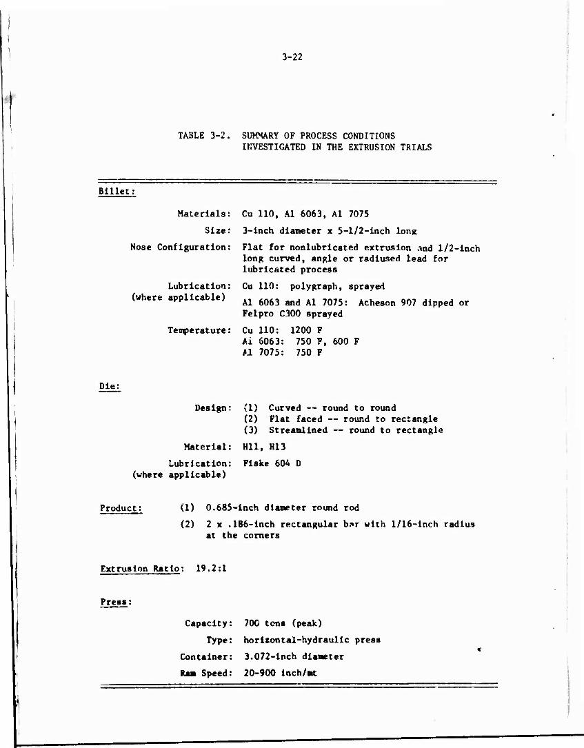
I !
Billet
3-22
TABLE 3-2. SUMMARY OF PROCESS CONDITIONS INVESTIGATED IN THE EXTRUSION TRIALS
Materials:
Size:
Nose Configuration:
Lubrication: (where applicable)
Temperature:
Cu 110, Al 6063, Al 7075
3-inch diameter x 5-1/2-inch long
Flat for nonlubrlcated extrusion And 1/2-inch long curved, angle or radiused lead for lubricated process
Cu 110: polygraph, sprayed
Al 6063 and Al 7075: Acheson 907 dipped or Feipro C300 sprayed
Cu 110: 1200 F Ai 6063: 750 F, 600 F Al 7075: 750 F
Die:
Design:
Material:
Lubrication: (where applicable)
(1) Curved — round to round (2) Flat faced — round to rectangle (3) Streamlined — round to rectangle
Hll, H13
Flske 604 D
Product: (1) 0.685-inch diameter round rod
(2) 2 x .186-inch rectangular b*r with 1/16-inch radius at the corners
Extrusion Ratio: 19.2:1
Press
Capacity: 700 tons (peak)
Type: horizontal-hydraulic press
Container: 3.072-inch diameter
Speed: 20-900 inch/mt

3-23
The press Is fully instrumented to measure the tot^l extrusion force on the stem,
the force on the die, the position of stem during extrusion, and the ram velocity,
Extruded Shapes
A round-cornered rectangle and an axlsymmetric round were the two
shapes extruded in this program.
A round-cornered rectangle was chosen since the rectangle can be
used as a module to form most of the extruded-structural shapes used in mili-
tary hardware. The round shape was extruded under similar conditions as the
rectangular shape, in order to evaluate the effects of extrusion and die
geometries on load and metal flow. Figure 3-10 gives the dimensions of the
extruded shapes.
Billet Materials and Preparation i i
The materials extruded were copper 110 and aluminum alloys 6063 and
7075. Copper 110 was extruded to study the metal flow under lubricated condi-
tions. This alloy is much easier to lubricate compared to Al 6063 and Al 7075.
It was felt that with Cu 110, the metal flow along the die surface would not
be affected by die pick-up problems associated with extrusion of aluminum
alloys. Aluminum alloy 6063 u^ extruded to establish the procedure fov
lubricated extrusion of Al 707.. As stated before, there are no cst lblished
procedures for lubricated extrusion of Al 7075. Tht« conventional practice is
to extrude this material without any lubrication of the billet and with some
lubrication on the die surface to ensure the separation of the die from the
rest of the billet after extrusion. Al 6063 is softer and easier to extrude
compared to Al 7075, and it is extruded at about the same temperature as Al
7075. Extruded structural parts for military applications are primarily made
of hard-aluminum alloys of 2000 and 7000 series (mostly Al 2024 and Al 7075).
Al 7075 was chosen as representative cf these hard-aluminum alloys.
Table 3-3 gives the heat treatment of the billet stock prior to
machining as well as the nose confl?jration of the machined billets used in
the trials. All billets had 2.993 ± 0.003-inch diameter and approximately
5.5-inch let?th.

3-24
3.00 Dia
Billet
__. /-¥— .062 R Typ
(a) Rectangular shope from a round billet. Area reduction -20:1
3.00 Dia
Billet
Product
(b) Round shape from a round billet. Area reduction £20:l.
FIGURE 3-1 RECTANGULAR AND ROUND SHAPES EXTRUDED IN THE TRIALS
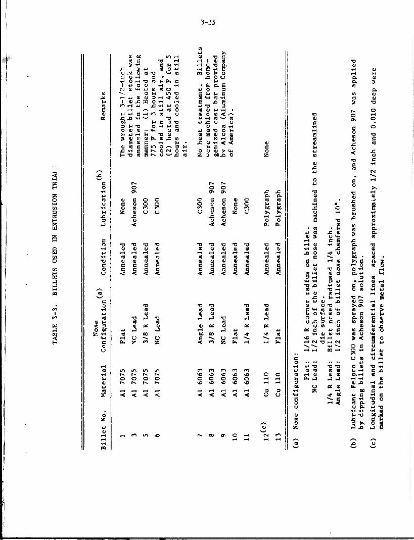
3-25
4J s-, <J, 60 m r-i CU fl ß n C fl r-l r-l 1 0) cfl 3 ■H C U -H r-4
§ 2 1 X 3 4-1 CD O 4J •H u *. 0 CO A «4-1 en 09 o > o c o r-l c « x 0 CJ
■H 0 iH fl CO t-c Pm o r4 1 4-1 o 01 •H -H ■ B a B
CM Ui U-l 4J 0] CO O 4J o 3 U) ^-, ra »-I m A g M u c Ji r-t 4-1 CJ 01 3 .-) <r n l*J Cfl i-t U 1 (U X 33 OH iH e x B n CO iH 4-1 £ Tl U O 4-1 fl 3 E rH /-N 4-1 CO O CO 01 4J rH • 0> 4J iH c r-1 en m v 0) c 10 < /-<
os x X 1-1 S^ "O t-l i-l Cfl *—' Cfl et h fi «fl 4J X U CJ 3 »* fl O TH 4-I C CJ CO i-l 0 V 01 •• <4-i r<J cfl 4-1 CO fl o u P 4-1 r-l l-l fl 0) cfl B oi o cu 3 2 1\' 01 f* tu x u> 01 N H e
e 01 C H r4 • X 01 •H < -5 0) m a c fi m o ^ 3 r-i t-l B c X -H c to N ON O Tl 0 CU 01 > "4-4 o H fl Cfl s r» o **• x co 85 3 00,0 0 z
6 en D
Cfl
d
en
W ce 3 o tv r. "H
C c u
01
2
c
e r-. o O
1-1 a\ 4-1 Cfl 0) c o c CJ c o c o fl o to c, m p 55 0) cj CJ
X! JC 3 u ►J <
O fl fl fl fl •H 01 0) 01 0) 4-1 iH 1-4 1-1 r-l 1-4 cfl CO CO 11'
fl 0) 01 01 01 r c c c c 0 u
c < 5 1 5
fl CO V
*J J CO
1-4 CJ U. 7
'S CJ ►J
oc
fl CO 0> -3
CJ z
m in ifi irt r^ r». r». r» O O O O r>» r«. r» *■»
■-I c\ in
r-. f* o o CT\ o\ X
o. x a
o c R 01 c « CO o CJ o e c u M en IA CO 0 CO u 01 CJ 0' 0) 55 CJ >> rV
X -*- 1-1 i-l Ü CJ o o < •< PH (X
fl fl fl fl fl fl fl CO 0) cu 0> 01 CU <V
1-4 r-l rH p-t r-l iH /-I cfl Cfl cfl s CO cfl cfl 0) OJ CU cu cu o c C c c c c c c < 3 < «i 1 1 1
fl fl cfl CO
0) ■J
o» a:
fl J
•H J 4-1 OC 00 cfl ^ 8 s ü H v <! m S5 ft, -i
fl cfl 01 -1
Cfl 1-4
f» m CO PO vO vO ^C vO C C O Q v£> *£> vC vO
O
< < < < <
r-. CD O ^
C C
3 3 CJ U
CM cn
0> •H OJ rH M (X Oi a 3 cfl
o- (0 n> rt 01 3 fl
r>. o fl C 1-1
01 ON o C • •H c o 1 O
CO fl cfl 01 c cu X cfl 1-1 CJ 4J CO
< fl
X o c
cu c iH x: CO 4J CM
o C r-l 4-1 o
r*. fl fl iH 0> 01 CU c X
• 0 O
X CO 3
CJ r-i
fl 01
u X
CO
iH K o U • CO • »- CO a
4J cfl X Oi 3 a 0) 3 CJ <4-l cfl
■H C B X •H 0) i-t ce a fl ■H CO X cfl 01 X) o St CJ r4 o
c *>» OC • cd • C r-t 0) >■> c
CO o o 4-1 CU 1-4 o 01 fl o o T-l rH
(13 H 01 c O. 4J ■M 3 r-t
§4J 3 Cfl
i-i i-l •» iH 01 r-l fl X •H 01 c C 5 2 CO fl i-i o (0 l-i 01 CO iH r-, g
X • h -H fl r-N t- 4J 0) X 01 *—\ rH 01 CJ fl >»o\ C« 0>
E 141 cfl 0) *4-i cfl ■H > o vw CO O t-. C 4J U
o U O a o a 01 01 CO u X 3 C X CO CO
o M CJ 01 K ja CC c 4-> C CO X 4) 0
IH 01 CU «rt Cfl CJ Is vC ■H f-t 3 < r-t CM fl rH CN ^» ^*^ 1-1 •^> o c U 1-1 l-( OQ •-» o i-i U u
■ • en "H 01 c CJ CO Ü rH 0 • • • • • • •• 4J rH
1-1 4-1 fl fl fl o 01 fl "H 4-1 CC CO Cfl CO h iH s-° CO f-4 01 cu oi O.r-1 l- b. J -J -J iH 1-1 CU 3 CU X -t X OL CJ 0£ Oi u. (0 4J
1-4 55 r-l oc c 14-1 sr oc 4-1 c •w e r o ^ § •H
a fl o
u o 1-1
a IH
U fl
■äjn 01 u fl te X e v. o 3 >, 5 S y. rJ X
t

3-26
Die Designs
Figure 3-llb shows the three extrusion dies iis.d in extruding rec-
tangular and round shapes.
For the lubricated extrusion of the rectangular product, a stream-
lined die was manufactured using "SHAPE", the system of computer programs
discussed earlier. The streamlined die has a curved surface which provides
a smooth transition from the round to rectangle shape. The die was made by
EDM process. The necessary tape for NC machining of graphite electrode was
prepared using "SHAPE". The electrodes vere machined on an NC (Numerical
Control) machine at Battelle. Figure 3-lla shows a photograph of the graphite
electrode and the streamlined die.
A flat-faced die was made for the nonlubricated extrusion of the
rectangular shape. For extruding the round shape, a curved die was also
fabricated, Figure 3-llb. All the three dies were dimensioned to give an
area reduction of 19.2. Detailed dimensions and the procedure of manufacturing
the dies are given in Appendix F.
Billet and Die Lubrication
Based on the previous experience at Battelle on lubricated extrusion
of aluminum alloys, Acheson 907 was selected initially as the billet lubricant.
This lubricant is said to be tenacious and suitable where the lubricated sur-
face is stretched extensively as in extrusion of shapes. However, after the
first set of trials, the billet lubricant was changed to Feipro C300. Prior
experience in extruding aluminum alloys was that the lubrication system of
Felpro C300 on billet and Fiske 604D on die and container had worked quite
well in past studies. For Cu 110, polygraph was selected, based on existing
extrusion practice. The container and the die were lubricated with Fiske 6G4D.
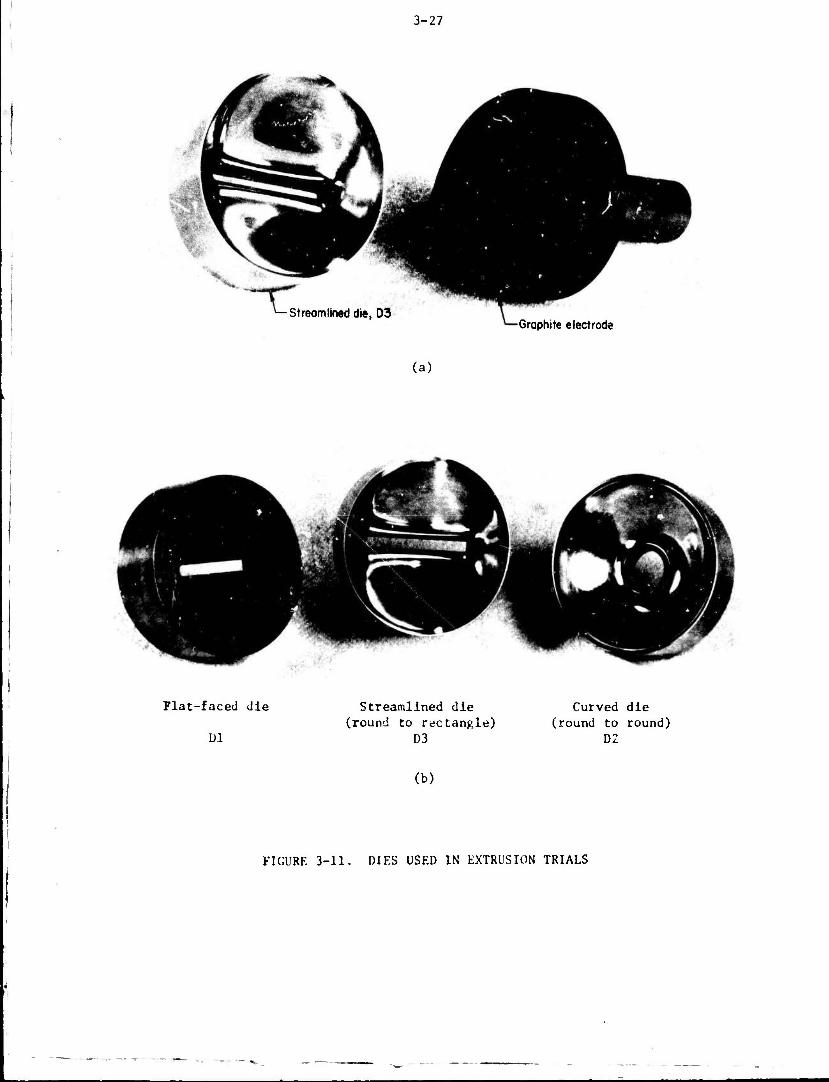
3-27
-Streamlined die, D3 Graphite electrode
(a)
Plat-faced die Streamlined die Curved die (round to rectangle) (round to round)
Dl D3 D2
(b)
FIGURE 3-11. DIES USED IN EXTRUSION TRIALS
3-28
Results of Extrusion Trials
The process conditions and the results of the extrusion trials are
listed in Table 3-4. In most trials, billets were extruded partially, and
small butts were left unextruded to observe billet lubrication and metal flow.
In the first set of trials, billets numbered 8, 3, 9, 10 and 1 were
extruded. Considerable die pick was observed in lubricated extrusion of
aluminum alloys. The die pickup was obviously due to the breakdown of lubri-
cation. Upon evaluation of the shape of the butt, this lubrication breakdown
was attributed to the presence of the die lip, shown in Figure 3-12a, which
scraped the billet material near the billet surface.
Figure 3-12a illustrates the tooling arrangement which caused
lubrication breakdown. The die sits freely in the container and has the die
lip in front of the billet. The lubrication breaks down when the lubricated
billet surface is either sheared by the lip, or deformed s»-verlv and possibly
forming a dead zone. It is obvious that with the present die-container
arrangement, it is not possible to completely eliminate this problem. After
evaluating the results of the first set of trials, it was concluded that the
pickup could be minimized by (1) modifying the die lip to a very thin and
sharp edge, and (2) by replacing Acheson 907, which contains polymers and
does not dry completely, with Feipro C300 as the billet lubricant. Previous
experiences had shown Feipro C300 to be quite effective in lubrication
of aluminum alloys.
Based on the above evaluation, the dies D2 and 1)3 were modified as
s!i..wn in Figure 3-12b. Also, Feipro C300 was used n% the billet lubricant
i> the subsequent trials. Table 3-4 also shows the rewrite of extrusions
conducted after making these changes. Although die pickup was no longer
severe, a thin foil, probably sheared by the sharp lip of the die, was found
in between the surface of the die and the butt. The possible shearing of the
billet surface by the die lip cannot be eliminated without making a major
change in the tooling arrangement, or in the die dimensions, used in the
present trials. Therefore, it was decided not to undertake anv malor change
in tooling and to terminate these preliminary trials, based on two considera-
tions:
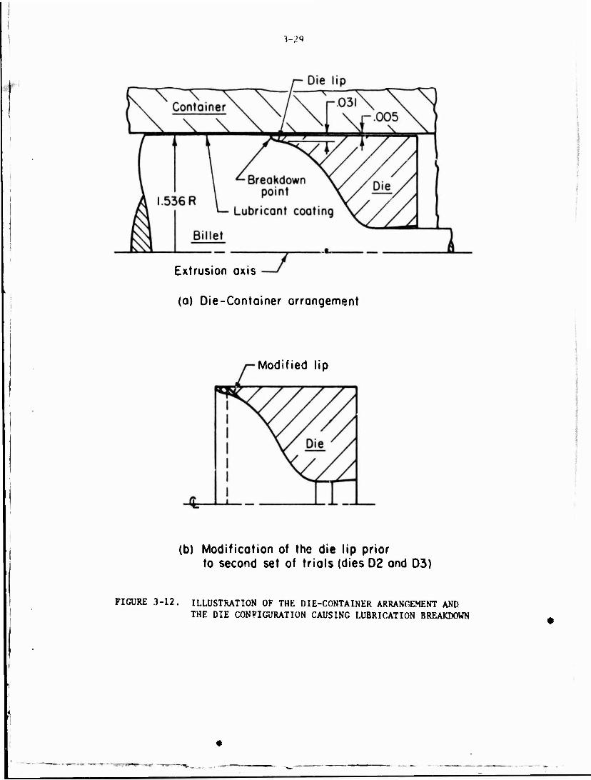
3-29
Extrusion axis
(a) Die-Container arrangement
Modified lip
(b) Modification of the die lip prior to second set of trials (dies 02 and D3)
FIGURE 3-12. ILLUSTRATION OF THE DIE-CONTAINER ARRANGEMENT AND THE DIE CONFIGURATION CAUSING LUBRICATION BREAKDOWN

t
<3 I
—' 03 <
•H if, U) r*
.X u CO
•■ E 0) 41 VJ CX 2 w 03 o> M p- e
3 c E o 1 0) •H 3 ?. u u X e w •3 1
•H X cd S?
3 Ul 73 ■H 0 C U •H
OH F*
OJ g 3
4-1 4J OJ RJ H 1J i-4 4) In
s §■ 0
0) H
•a ü u n 01 o. »1 to —
C E •H itj
DC
<—* (tj
W
4/ TH
O
ec JO 3
3-30
TJ n. a. Oi 3 a 3 .Ü J>! 3 -* CJ u J*i cj CO <H ü
•H ^ & •H 1 1 a
01 a i i
01 01 -H 01 ■H •H 73 •H a a Q
o CO
r—i U-c 4.-1 •H U 4-1 0 3 3
IH a -o
C Si 0) •H X X £■ u 4J u
c 14-1 < 0 o
-3- 00
CO vO in 00
Ol H <I m m cr
0> <r vO m oc m m 00 00 r^
o o «1 1-4
4-1 • - eg
73 -H O IH O 4-1
u •j X w
c c 01 01
r-l rH r-l r-l
73 0) 0) 0 y ej
5 X X w w
o O o C in m in in r-» rv r^ r-s
m
O
Q
•* «» «» odd
CO r-( iH D O O
TJ 73 O O
5 $
c c c c CM CN
m in cj\ en
7J *c •c 73 0 0 0 0 c e 5 0
c 8
c c
m c
O o
o in
c oo
r-~ --* r» o c O C3-. Ox o c 0 § c
0 (/> in X 41 01 01 4J 01 X J= JS c c
CJ CJ u 0 0 < < < z z
JC D m i> ex. >.
•H o
ex
0) ■-*
P"l 14-1
T)
J= a CO u oi
01 CN >*, C -H
■o 01
•a oi
CO 14-4 Clln C -H 0 -H
73 0
01
CN 14J O -H
TJ
2 §
o rx
o o S o 1*1 CO
o o cn
cn m vO r~ O o vD r~
en en m
O O c S4J *C r^
c c
3 3 U CJ
m vC c c C o
0 u 7. 41 (/) u 41 «J
•-I (B r* M
<3N C rt
Ä
CO J3
0J a CO
J3 to
CO »J r-l rt 3
r-t 0£ 3 0) C ot a 3 C CO 4J CO J3 y 4-1 0) 01 CJ U 41 73 I- C U
3 O b O 'H o >-.
14- 01 U -H
0 O 73
73 73 41 41
41 -H C U 73 -H CO ^j
14-1 73 B t 01 CO
4J > 41 CO U U
—I 3 4J U- CJ to
U I! I
r-i CN cn Q O O
oi
a
o o m
cn « 2 4) U 3
4-1 CO M 0)
§■
l-l 01 c
c o u Oi
J3
3 IJ 4J X 01
CC
c
c

3-31
(1) The main objective of evaluating the capabilities of
CAD/CAM techniques was completely achieved by measur-
ing the extrusion load, the metal flow, and the dimen-
sions of the streamlined die, manufactured bv CAM
method.
(2) The lubrication breakdown problem was caused bv the
unconventional die design and die-container arrangement
used in these preliminary extrusions. The problem may
be totally eliminated bv using a conventional hydrostatic
or cold extrusion tooling arrangement, used in other
extrusion studies, conducted at Battelle.
In extruding copper, the grid lines marked on the surface of the
billet were quite visible on the butt. These grid lines were used to determine
the metal flow along the die surface.
Evaluation of Results
Metal Flow
The surface of a streamlined die for lubricated extrusion is determined
by the geometrical construction illustrated in Figure 3-2. The following assump-
tions are made in deriving the die surface:
(1) The billet undergoes deform.ition with minimum amount
of work expended for redundant deformation and friction.
This requires that the friction at the billet-container
and billet-die interfaces should be minimum. Thus, the
error introduced by this assumption would depend on the
values of friction factor considered at the sliding
surfaces.
(2) The metal flow is such that there is a neutral axis per-
pendicular to the cross-sectional plane at the die
entrance. This is strictlv true onlv for axisymmetric
extrusion. In extrusion of shapes, there is probablv a
complex neutral surface Instead of a neutral axis. This
assumption was made to simplify the analysis as the
neutral surface cannot be determined without constructing
•
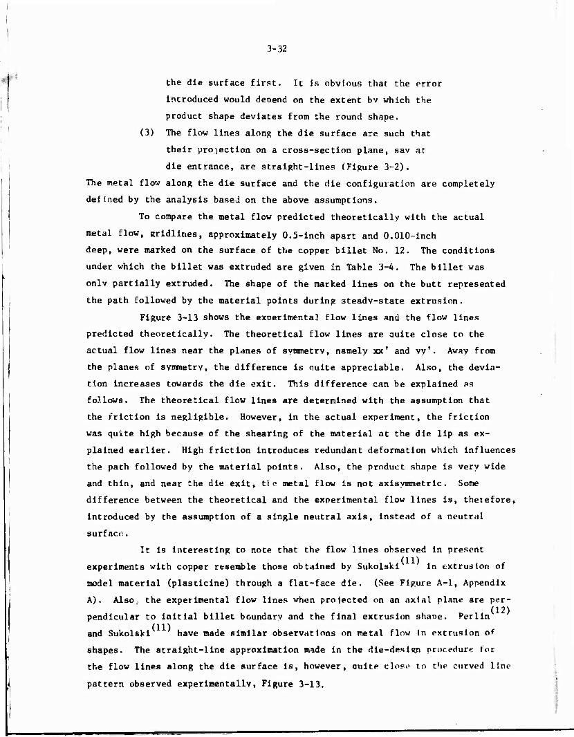
3-32
the die surface first. It is obvious that the error
introduced would depend on the extent bv which the
product shape deviates fron the round shape.
(3) The flow lines along the die surface are such that
their projection on a cross-section plane, sav at
die entrance, are straight-lines (Figure 3-2).
The metal flow along the die surface and the die configuration are completely
defined by the analysis based on the above assumptions.
To compare the metal flow predicted theoretically with the actual
metal flow, gridlines, approximately 0.5-inch apart and 0.010-inch
deep, were marked on the surface of the copper billet No. 12. The conditions
under which the billet was extruded are given in Table 3-4. The billet was
onlv partially extruded. The shape of the marked lines on the butt represented
the path followed by the material points during 3teadv-state extrusion.
Figure 3-13 shows the exoerimental flow lines and the flow lines
predicted theoretically. The theoretical flow lines are guite close to the
actual flow lines near the planes of svmmetrv, namely xx' and vy'. Away from
the planes of symmetry, the difference is ouite appreciable. Also, the devia-
tion increases towards the die exit. This difference can be explained as
follows. The theoretical flow lines are determined with the assumption that
the friction is negligible. However, in the actual experiment, the friction
was quite high because of the shearing of the material at the die lip as ex-
plained earlier. High friction introduces redundant deformation which influences
the path followed by the material points. Also, the product shape is very wide
and thin, and near the die exit, tie metal flow is not axisymmetric. Some
difference between the theoretical and the experimental flow lines is, thetefore,
introduced by the assumption of a single neutral axis, instead of a neutral
surface.
It is interesting to note that the flow lines observed in present
experiments with copper resemble those obtained by Sukolski in extrusion of
model material (plasticine) through a flat-face die. (See Figure A-l, Appendix
A). Also, the experimental flow lines when prolected on an axial plane are per- (12)
pendlcular to initial billet boundary and the final extrusion shaoe. Perlin (11)
and Sukolski have made similar observations on metal flow In extrusion of
shapes. The straight-line approximation made in the die-desisn procedure tor
the flow lines along the die surface is, however, auite clost» to the curved line
pattern observed experimentally, Figure 3-13.
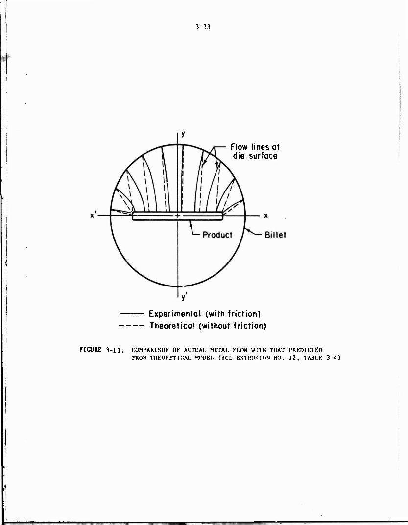
3-13
Flow lines at die surface
Experimental (with friction) Theoretical (without friction)
FIGURE 3-13. COMPARISON OF ACTUAL METAL FLOW WITH THAT PREDICTED FROM THEORETICAL MODEL (BCL EXTRUSION NO. 12, TABLE 3-4)
3-34
Extrusion Pressure
As mentioned earlier, "SHAPE", the svscew of computer program developed
in this prolect, includes a theoretical analysis for predicting the pressure
required to extrude a shape. In the analysis, the extrusion pressure it- deter-
mined as a function of flow stress of the material, frictional conditions at
the sliding surfaces and process conditions, such as ram speed, billet tempera-
ture, dimensions of billet and the extruded shape, and die configuration. Thus,
to predict the extrusion pressure under given process conditions, inforriation
on flow stress of the material and on friction factors for the sliding surfaces
is needed. Existing data on flow stress of materials is very limited. Reference
15 gives the flow-stress data for some materials. The friction factors for
container-material and die-material interfaces depend upon some of the process
conditions, such as nature of lubrication, temperatures of the contacting sur-
faces, and the surface finish of the tooling, etc. A special test must be
designed and conducted to obtain accurate values of friction factors.
To obtain data on flow stress of the materials, extruded in this study,
the ideal procedure would have been to conduct isothermal compression or torsion
tests with specimens made from billet, stock. However, due to the limited scope
of the trials, separate-isothermal compression tests were not conducted. Instead,
ry.j3ting flow stress data from Reference 15 were used. Since the data on Al 6063
was not available, the flow stress of Al 1100, which is quite similar to Al 6063,
was used.
In the first set of extrusion trials, the extrusions through the dies
were virtually without lubrication because of severe die galling. Therefore,
the following values of friction factors were assumed for the first set of
trials:
• Iriction factor at die-material interface, m, ■ 1.0
• Friction factor at container-material interface, m ■ 0.15. c
With these friction factors, the maximum extrusion pressures were calculated
using "SHAPE". The predicted and the experimental values of extrusion pressures
are given in Table 3-T. Comparison between the experimental and predicted extru-
sion pressures is fair. The predicted pressures are always higher than the
experimental values and the maximum difference is about 23 percent. Lack of
proper information on friction conditions at the sliding surfaces and on flow
stress data seem to be the probable reasons for the difference.
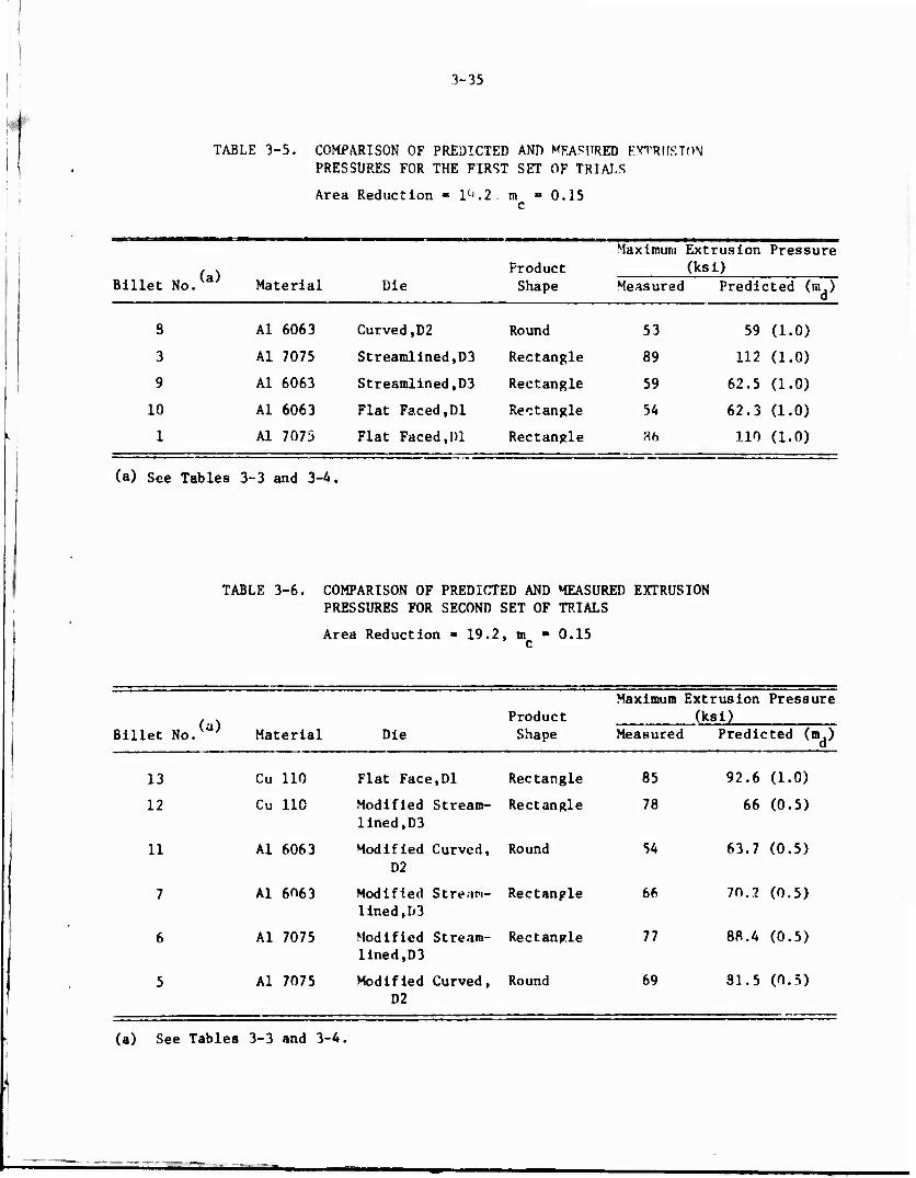
3-35
TABLE 3-5. COMPARISON OF PREDICTED ANT) MEASURED EXTRUSION PRESSURES FOR THE FIRST SET OF TRIALS
Area Reduction = lc-.2 m = 0.15 c
Maximum Ext rusion Pressure
No>> Material Die Product Shape
(ks i) Billet Measurec 1 Predicted (m.)
d
8 Al 6063 Curved,D2 Round 53 59 (1.0)
3 Al 7075 Streamlined ,D3 Rectangle 89 112 (1.0)
9 Al 6063 Streamlined ,D3 Rectangle 59 62.5 (1.0)
10 Al 6063 Flat Faced, Dl Rectangle 54 62.3 (1.0)
1 Al 7075 Flat Faced, 1)1 Rectangle Ah 110 (1.0)
(a) See Tables 3-3 and 3-4,
TABLE 3-6. COMPARISON OF PREDICTED AND MEASURED EXTRUSION PRESSURES FOR SECOND SET OF TRIALS
Area Reduction « 19.2, m »0.15 c
Billet No (a)
Material Die
Maximum Extrusion Pressure Product (ksi) Shape Measured Predicted (m.)
d
13
12
11
7
6
5
Cu 110 Flat Face,Dl Rectangle
Cu 110 Modified Stream- lined,D3
Rectangle
Al 6063 Modified Curved, D2
Round
Al 6063 Modified Strean- lined,D3
Rectangle
Al 7075 Modified Stream- lined,D3
Rectangle
Al 7075 Modified Curved, D2
Round
85
78
54
66
77
f>9
92.6 (1.0)
66 (0.5)
63.7 (0.5)
70.2 (0.5)
88.4 (0.5)
31.5 (0.5)
(a) See Tables 3-3 and 3-4.

3-36
As mentioned earlier, after the first set of trials, the streamlined
die, D3, and the curved die, D2, were modified to improve lubrication. However,
partial lubrication was only achieved due to the shearing of a thin foil hv the
die lip. Friction factor m, was assumed to be 0.5 and m was taken to he 0.15 d c
in calculating the pressures. The predicted pressures are piven in Tahl.- 3-6.
Again, the predicted pressures are quite close to the actual pressures, the
maxt'Tium difference being 18 percent. The difference 1s attributed, as before,
to Inadequate information on flow-stress data and on frictional conditions
,ii Uu Jit--material interface.
it is interesting to look at the effect of product shape on extrusion
pressure. Comparing extrusion pressures for billet numbers 11 and 7, the effect
of change of shape from a round to a thin rectangle is to increase the pressure
by 22 percent. With billets numbers 6 and 5, the increase in pressure is about
12 percent. Qualitatively, this trend agrees with the theoretical results,
obtained earlier in studying the extrusion of a modular elliptic shape, Chapter
2, and with earlier work. The increase in pressure with change cf extrusion
shape can be explained as follows: The deformation is axisvmmetric when a
circular shape is extruded from a cylindrical billet. However, when the product
shape is noncircular, additional redundant work is expended to deform the
material to the nonaxisymmetric shape. Also, the calculated surface area of
the streamlined die for extruding the rectangular shape is larger than the
surface area of the die for extruding the round shape. This increases the
energy dissipated in overcoming friction. The total effect is to increase the
total extrusion pressure.
Conclusions
From the results of the extrusion trials, the following conclusions
are drawn:
(a) The desired streamlined surface was machined on the
EDM electrode with NC tape prepared frora SHAPE, the
system of computer programs developed in this project.
The NC programs, therefore, are found to be correct
and adequate for simple shapes like a round-cornered
rectangle.
3-37
(b) The extiusion pressures predicted bv SHAPE agreed
reasonably well with the experimental values. The
maximum difference was about 23 percent. The
simplified theory developed In this program seems
to be sufficiently accurate for predicting extru-
sion loads for practical purposes.
(c) The comparison between the actual metal flow along
the die surface, obtained from extrusion trials, and
the assumed direction of flow in the die design was
only fair. High-frictional conditions at the material
die interface were partly responsible for the difference,
(d) Proper billet lubrication is very important in shape
extrusion. Due to the high area reductions and the non-
axisymmetric nature of the deformation, portions of the
billet surface are stretched to a high degree. The
lubricant film must be capable of stretching with the
surface. Also, the die design from the point of view
of lubrication is vt-rv important. The billet surface
must be deformed smoothly without causing lubrication
breakdown.
SUMMARY
This chapter describes the work conducted towards applving CAD/CAM
(Computer-Aided Design/Computer-Aiued Manufacturing) to extrusion of siinnle
structural shapes. Even tor simple shapes like T's and L's, the surface of
a streamlined die cannot be defined analytically. No consistent technique
has been developed to define a:.d manufacture complex surfaces of a stream-
lined die. In this work, a turner cal method of determining the shape of a
streamline die in lubricated extrusion is presented.
A simplified, uniforr energv method is developed to calculate the
extrusion load and it components due to internal deformation, shear deforma-
tion, and friction. Dit v-*ssure distribution along the die surface is also
calculated. Information on load and pressure distribution should help in
optimizing the extrusion process, and in proper selection of the extrusion

3-38
press as well as in proper design of tooling.
The streamlined die surface is too complex to be machined easily by
conventional techniques like copy turning or milling. Therefore, special-
purpose computer programs are written to generate the die surface by NC
(Nuc^rlcal Control) machining. The programs can be used to machine an EDM
(Electro-Discharge Machining) electrode for manufacturing the dies by EDM
process, or a master pattern can be machined which may be used to cast the dies.
The computer programs to define the surface of a streamlined die, to
calculate the load and u.te-pressure distribution, and to generate coordinate
data for machining of the streamlined die are put together in a system of
programs called "SHAPE". SHAPE can be used in batch, as well as in interac-
tive mode. In the Interactive mode, the designer can interact with the program
to select the shape and the It ^th of the die, and to obtain information on
load and pressure calculation as well as to select the proper size cutter for
NC machining of the dies.
Extrusion trials were conducted to demonstrate the CAD/CAM techniques
developed in the progiam. A round-cornered rectangle and a circular shape were
extruded from copper 110, Al 6063, <ind Al 7075, under lubricated and nonlubri-
cated conditions. For lubricated extrusion of the rectangular shape, a stream-
lined die was designed and fabricated with the help of the developed software
package, SHAPE. A flat-faced die was made for nonlubricated extrusion of the
rectangular shape. Round shapes were extruded with a curved die to evaluate
the effect of shape on extrusion pressure and metal flow. The results showed
that the desired optimal die shape was machined with the NC program*. The
agreement between measured values and theoretical predictions concerning metal
flow and extrusion loads was quite good. Thus, the results have demonstrated
the applicability and accuracy of the CAD/CAM techniques developed in the
present program.

3-39
REFERENCES
(1) Akeret, R., "Unconventional High-Speed Extrusion Processes for the Harder Aluminum Alloys", (in German), L. Metallkunde, 64, 1973, pp 311-319.
(2) Lahoti, G. Ü., and Altan, T., "Prediction of Temperature Distributions in Tube Extrusion Using a Velocity Field Without Discontinuities", Proceedings of the Second North American Metalworking Research Conference, Madison, Wisconsin, May 20-22, 1974, pp 209-224.
(3) Seeds, W. E., "Preform Design for Gas Turbine Blades", Engineering Materials and Design, November, 1973, pp 27-31.
(4) Hill, R., The Mathematical Theory of Plasticity, Oxford at the Clarendon Press, 1950.
(5) Chen, P. C. T., and Ling, F. F., "Upper-Bound Solutions to Axisymmetric Extrusion Problems", International Journal of Mechanical Sciences, Vol. 10, I960, p 863.
(6) Siebel, E., "Fundamentals and Concepts of Forming", (in German), Werk- stattstechnik und Maschinenbau, 40_, 1950, p 373.
(7) Kamyab, S., and Alexander, J. M., "Pressure Distribution in Hydrostatic Extrusion Dies", Journal of Strain Analysis, Vol. 17, No. 3, 1972, p 205.
(8) Doble, G. S., "Manufacturing Technology for the Extrusion of Superalloy Structural Shapes", Technical Report AFML-TR-68-325, October, i968.
(9) Lahoti, G. D., and Altan, T., "Optimum Die Profile for Drawing of Shells and Cups", Proceedings of Third North American Metalworking Research Conference, Carnegie Press, Carnegie-Mellon University, Pittsburgh, Pennsylvania, May, 1975.
(10) Nagpal, V., and Altan, T., "Analysis of the Three-Dimensional Metal Flow in Extrusion of Shapes with the Use of Dual Stream Functions", Proceedings of Third North American Metalworking Research Conference, Carnegie Press, Carnegie-Mellon University, Pittsburgh, Pennsylvania, May, 1975.
(11) Annual Report to the Extrusion Committee for 195b by P. J. Sukolski, The British Iron and Steel Research Association Report MW/G/83/56.
(12) Perl in, i. L., "Theory of Metal Extrusion", Published by Metallurgiya, Moscow, 1964, Foreign lracslation No. FTD-HT-23-616-67, June, 1968.
(13) Dorn, W. S., and McCracken, D. D., Numerical Methods with FORTRAN IV Case Studies, John Wiley and SOPS, New York, 1972.
--»■—~"»-» mi*mm

3-40
(14) Perlmutter, I., DePierre, V., and Pierce, C. M., "Lubrication as a Parameter in the Extrusion of Metals", Friction and Lubrication in Metal Processing, ASME, 1966, pp 147-161.
(15) Douglas, J. R., and Altan, T., "A Study of Mechanics of Closed-Die Forging - Phase II", Final Report, Contract DAAG46-/l-C-0095, Battelle's Columbus Laboratories, Columbus, Ohio, November, 1972.
(16) Abson, D. J., and Gurney, F. J., "Investigation of Parameters Involved in Metal Processing Operation", Technical Report AFML-TR-73-281, December, 1973.

APPENDIX A
DETERMINATION OF THE DIE GEOMETRY

APPENDIX A
DETERMINATION OF THE DIE GEOMETRY
In shape extrusion, the die must provide a smooth transition from
the circular billet to the final extrusion shape. In addition, the die sur-
face must be such that the material undergoes minimum redundant deformation
and exits from the die with a uniform velocity. The shape of the die sur-
face affects the metal flow. To obtain an optimal die design, the usual
procedure is to analyze the characteristics of metal flow through dies of
different configurations and to select the die configuration which provides
the desired metal flow. As a first step of this procedure, the die shape
must be defined analytically or numerically.
Any definition of the die surface must fulfill two requirements.
First, the definition should be as general as possible so that in the optimi-
zation process maximum possible die configurations are compared. Second, the
definition should allow modifications in a portion of the die surface without
affecting the remaining surface. This would make simpler the process of modify-
ing a die profile based on experimental studies* Die surface modifications
may be desired to obtain more uniform metal flow or to relieve stress concen-
trations at particular locations in the die.
In extrusion of round bars or elliptic shapes, it is possible to
define the die surface analytically. For nonsymmetric shapes, like T, L, U
and others, it is rather difficult to describe analytically the complex die
surface which provides a smooth transition from a round cross section to these
extruded shapes. Consequently, a numerical procedure is used to describe the
die surface. This procedure is based on simplified principles of theorv of
plasticity, and previous analytical and experimental studies conducted on
shape extrusion.
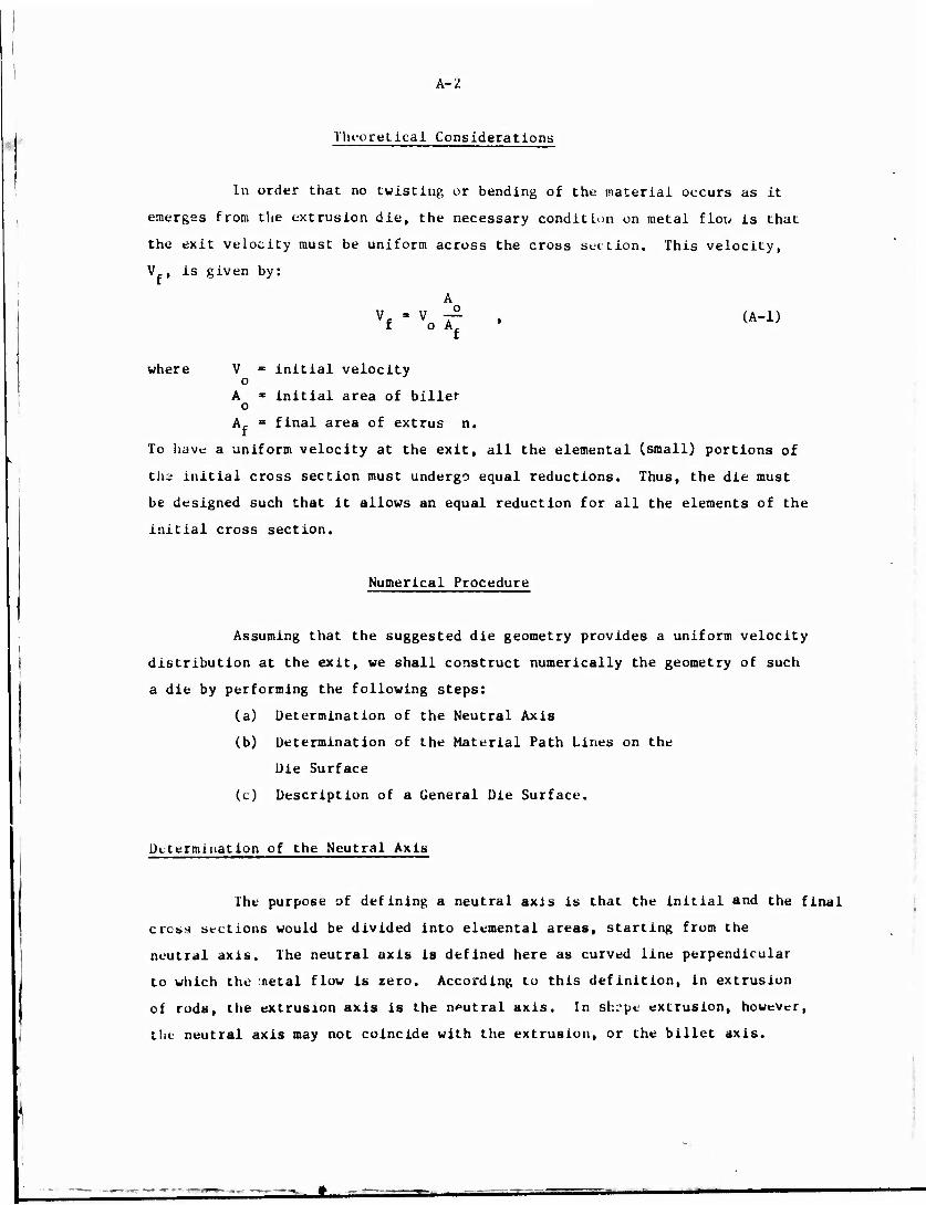
A-2
Theoretical Considerations
In order that no twisting or bending of the material occurs as it
emerges from the extrusion die, the necessary condition on metal flow is that
the exit velocity must be uniform across the cross sec Lion. This velocity,
Vf, is given by:
vf " vo Tt • <A-:>
where V * initial velocity o
A * initial area of billet o
A = final area of extrus n.
To have a uniform velocity at the exit, all the elemental (small) portions of
tha initial cross section must undergo equal reductions. Thus, the die must
be designed such that it allows an equal reduction for all the elements of the
initial cross section.
Numerical Procedure
Assuming that the suggested die geometry provides a uniform velocity
distribution at the exit, we shall construct numerically the geometry of such
a die by performing the following steps:
(a) Determination of the Neutral Axis
(b) Determination of the Material Path Lines on the
Die Surface
(c) Description of a General Die Surface.
Determination of the Neutral Axis
The purpose of defining a neutral axis is that the initial and the final
cross sections would be divided into elemental areas, starting from the
neutral axis. The neutral axis is defined here as curved line perpendicular
to which the oetal flow is zero. According to this definition, in extrusion
of rods, the extrusion axis is the neutral axis. In shrpe extrusion, however,
the neutral axis may not coincide with the extrusion, or the billet axis.
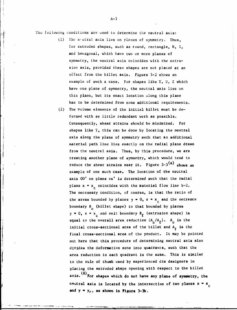
A-3
The folJüwing conditions are used to determine the neutral axis:
(1) The n'-utral axis lies on planes of symmetry. Thus,
for extruded shapes, such as round, rectangle, H, I,
and hexagonal, which have two or more planes of
symmetry, the neutral axis coincides with the extru-
sion axis, provided these shapes are not placed at an
offset from the billet axis. Figure 3-2 shows an
example of such a case. For shapes like T, U, Z which
have one plane of symmetry, the neutral axis lies on
this plane, but its exact location along this plane
has to be determined from some additional requirements.
(2) The volume elements of the initial billet must be de-
formed with as little redundant work as possible.
Consequently, shear strains should be minimized. For
shapes like T, this can be done by locating the neutral
axis along the plane of symmetry such that an additional
material path line lies exactly on the radial plane drawn
from the neutral axis. Thus, by this procedure, we are
creating another plane of symmetry, which would tend to
reduce the shear strains near it. Figure 3-3'a' shows an
example of one such case. The location of the neutral
axis 00' on plane xx' is determined such that the radial
plane x - x coincides with the material flow line b-2. r c The necessary condition, of course, is that the ratio of
the areas bounded by planes y - 0, x ■ x and the entrance
boundary B (billet shape) to that bounded by planes
y - 0, x - x and exit boundary B, (extrusion shape) is
equal to ehe overall area reduction (A /A,). A is the ^ o r o initial cross-sectional area of the billet and A, is the
final cross-sectional area of the product. It may be pointed
out here that this procedure of determining neutral axis also
divides the deformation zone into quadrants, such that the
area reduction in each quadrant is the same. This is similar
to the rule of thumb used by experienced die designers in
placing the extruded shape opening with respect to the billet (8)
axis. For shapes which do not have any plane of symmetry, the
neutral axis is located by the intersection of two planes x • x(
and y - yr, as shown in Figure 3-3b.
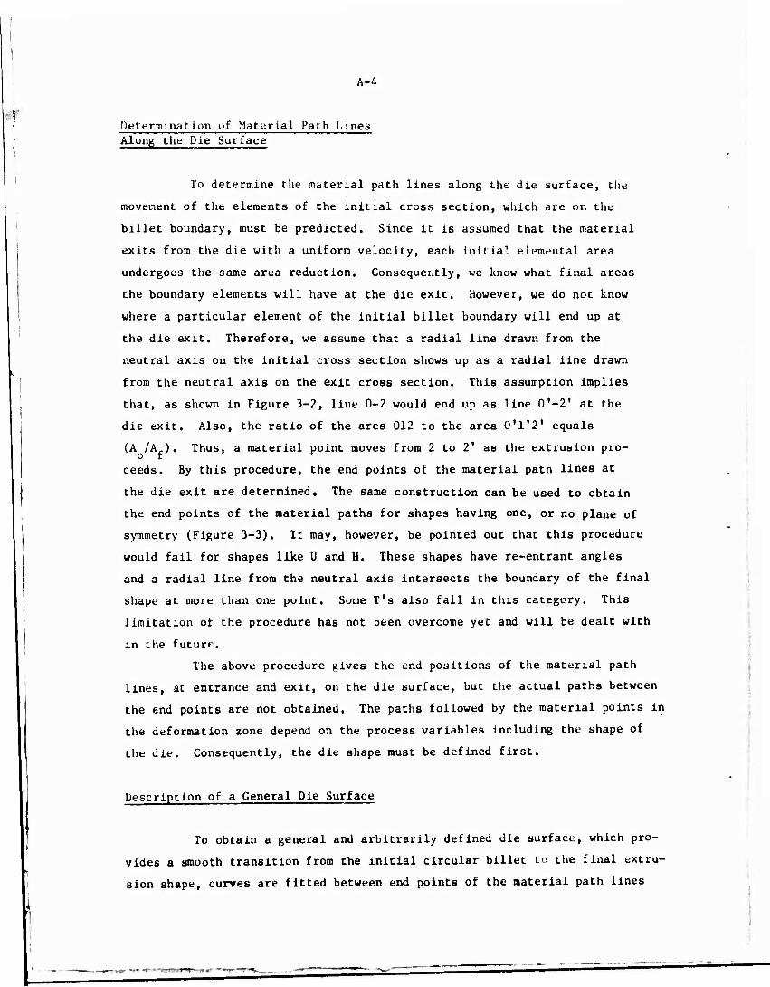
A-4
Determination of Material Path Lines Along the Die Surface
To determine the material path lines along the die surface, the
movement of the elements of the initial cross section, which are on the
billet boundary, must be predicted. Since it is assumed that the material
exits from the die with a uniform velocity, each initial elemental area
undergoes the same area reduction. Consequently, we know what final areas
the boundary elements will have at the die exit. However, we do not know
where a particular element of the initial billet boundary will end up at
the die exit. Therefore, we assume that a radial line drawn from the
neutral axis on the initial cross section shows up as a radial line drawn
from the neutral axis on the exit cross section. This assumption implies
that, as shown in Figure 3-2, line 0-2 would end up as line 0'-2' at the
die exit. Also, the ratio of the area 012 to the area 0'1'2' equals
(A /Af). Thus, a material point moves from 2 to 2' as the extrusion pro-
ceeds. By this procedure, the end points of the material path lines at
the die exit are determined. The same construction can be used to obtain
the end points of the material paths for shapes having one, or no plane of
symmetry (Figure 3-3). It may, however, be pointed out that this procedure
would fail for shapes like U and H. These shapes have re-entrant angles I
and a radial line from the neutral axis intersects the boundary of the final
shape at more than one point. Some T's also fall in this category. This
limitation of the procedure has not been overcome yet and will be dealt with
in the future.
The above procedure gives the end positions of the material path
lines, at entrance and exit, on the die surface, but the actual paths between
the end points are not obtained. The paths followed by the material points in
the deformation zone depend on the process variables including tht- shape of
the die. Consequently, the die shape must be defined first.
Description of a General Die Surface
To obtain a general and arbitrarily defined die surface, which pro-
vides a smooth transition from the initial circular billet to the final extru-
sion shape, curves are fitted between end points of the material path lines

A-5
at the die entrance and exit. Thus, numerically, a general three-dimensional
die surface is described. Different die surfaces can be obtained by changing
the curves fitted between the end points. Also, any portion of the die sur-
face can be modified without affecting the remaining surface by changing the
curves fitted in that portion.
The choice of the curves fitted between the boundaries of the deforma-
tion zone is based on theoretical considerations, previous experience, and
intuition. In extrusion of axirymmetric shapes like rods or tubes, previous (9)
studies at Battelle have shown that a polynomial curve gives the optimal
die shape. For axisymmetric shapes, this curve lies on a radial plane, i.e.,
a plane which contains the billet axis. However, for a nonsymmetric shape,
: c
(11)
theoretical and experimental studies ' have shown that the flow lines do
not lie on a radial plane. In extrusion through flat-faced dies, Sukolski
observed froc. nis model experiments that the flow lines, when projected on an
axial plane, (i.e., a plane perpendicular to the billet axis), were perpendicu-
lar to the initial billet boundary and the final extrusion shape, as shown in
Figure A-l. Similar observation on the pattern of metal flow in shape extrusion (12)
has also been made by Perlin for nonlubricated extrusion through flat-faced
dies. In lubricated extrusion process, the flow pattern derived theoretically
in our earlier work on extrusion of an elliptical shape from a cylindrical
billet also exhibits this characteristic. However, this flow pattern is for a
simple modular shape of an ellipse which does not h««e any sharp corners or
re-entrant angles. For more complex structural shape« like U and H, it is not
possible to predict whether the flow lines in the die would still be perpendi-
cular to the initial and final shapes or not. Model studies and trials to be
conducted later in this project are expected to provide some Information on
this point.
In view of the above observations made in this study, it was decided
to use a simplified procedure for describing the die surface. It was assumed
that the curves representing the tl.v lines lie on a plane containing the
billet axis, as seen In Figure 3-4. AASO, the curves themselves have a
polynomial form which have been shown to be the optimal shape for rod or tube
extrusion. Appendix •) gives the mathematical details of this construction.
A-6
a>
c <
o c in
3
o
s
as
'O
C r-(
■H

APPENDIX B
CALCULATION OF EXTRUSION LOAD AND DIE PRESSURE DISTRIBUTION

APPENDIX B
CALCULATION OF EXTRUSION LOAD AND DIL PRESSURE DISTRIBUTION
Siebel's method has been extensively used to analyze plane strain
as well as axisymmetric metal-forming prcblems. Here, this method is extended
to analyze the three-dimensional problem of shape extrusion. The following
assumptions are made:
(1) Plane sections perpendicular to the extrusion axis
remain plane.
(2) The plastic deformation zone is bounded by cross-
sectional plants at entrance and exit of the die.
(3) The effective strains, effective strain rates and
the flow stress of the deforming material is
assumed to vary only in axial direction (direction
of extrusion).
(4) In calculating the effective strains and strain
rates, the redundant shear strains and strain rates
are neglected. In calculating flow stress, this
assumption would introduce only insignificant error
since for hot extrusion, flow stress is a weak
function of strain rate for most materials. In the
calculation of rate of energy dissipation due to
plastic deformation, this assumption would Introduce
an error which previous experience* • ' has shown to be
small at least for plane and axisymmetric problems.
(5) Maximum extrusion pressure occurs at the very beginning
of the ftteady-state extrusion process when the material
jusc starts to exit from the die.
(6) Friction is taken into account by assuming that the
friction shear stress (?) is directly proportional to
the flow stress (0) of the material, i.e.,
i - ^ » . n ■ is a constant of proportionality and is called friction
•hear factor.
i
14—2
Theoretical Analysis
The total rate of energy supplied (E ) at any instance must be equal
to the sum of the rates of energy dissipated during the extrusion process.
This is expressed by the Equation:
. Et " Efc + Ei + Esh + Efd + hi • (B-X>
The symbols used are explained in the Nomenclature at the end of this Appendix.
The various terms of Equation (B-l) are determined as follows:
Kate of Energy Supplied (E )
The rate of energy supplied is given by:
E„ - P V - ~ D 2 P V . (B-2) t t o 4 o avg o
P is the total extrusion load and P is the mean pressure required to extrude t avg r ^
the material.
Rate of Energy Dissipated Due to Container Friction (Efc)
The rate of energy lost due to friction at the container wall is given
by:
i. - IID L T V • y- D 2 P, V . (U-3) fc occo 4 o fco
•t Is the shear stress due to friction at the material-container Interface and c
is given by relation:
T - m — . (B_4) C C ft
From Equation (Ü-3)» the component of extrusion pressure due to friction (I' ) is:
4L i - i
£c Do I C /S I

B-J
In the analysis, the flow stress ö Is taken to be a function of strain, strain
rate and temperature. Since the billet in the container is not plastically
deforming, the flow stress 5 in expression (B-5) corresponds to the yield stress
(5 ) of the incoming material at the billet temperature.
As extrusion proceeds, the length of tne billet in contact with the
container (Lc) decreases. L , which correspords to the maximum extrusion pres-
sure, is given by:
Lc " Lo " T (VL + AfV * (B"6) o
Rate of Energy Dissipated Due to Internal Deformation (E^)
E, - E, . , + E . , i ideal red
where E., » ideal rate of energy dissipation needed for the reduction
in cross-sectional area and shape
E - redundant rate of energy dissipated in causing the change
in cross section and shape. * E. , , for 2 work-hardening material is given by: ideal
E.. - A V / 5 de - ideal o o J VoPid ' <B"7>
c
The expression (B-7) is evaluated numerically. The deformation zone is divided
into a number of slabs. The flow stress in any slab is determined corresponding
to the total effective strain and strain rate in that slab.
For axisynunetric deformation, the effective strain, c, at any cross
section of area A of the deformation zone is given by:
I - In (A0/A) , (B-b)
whereas for plane-strain deformation
I - 2//3 In (A0/A) . (B-9)

B-4
Since initially the billet is cylindrical, the deformation in the beginning of
the deformation zone corresponds to the axisymmetric case. Ti.arefore, Equation
(B-b) is used in calculating the total effective strain. By definition, the
effective strain rate e is:
1 de e =dT •
In case the plane sections remain plane, the strain rate in finite difference
form is given by:
e - ff ' Vz , (B-10)
where V - axial velocity z '
Az = small distance over which the difference in strain, Ae, is
measured.
The flow stress at any section is determined from the flow stress
data corresponding to the strain rate and strain calculated from Equations (i'.-o,
and (B-10). The shear strains are not included in Equations (B-8) and (B-iUj,
which are really the expressions based on ideal deformation.
The component E , cannot be determined without the knowledge of
strain-rate distribution in the plastic zone. The study on the modular
elliptic shape, however, indicated that the contribution of the component
E , to extrusion load is small in relation to the other components. Thus, at
the present time, E , is neglected in calculating extrusion load and die pres-
sure distribution.
Rate of Energy Dissipation Due to Tangential Velocity Discontinuities (ERh)
Ts« concept of having a tangential velocity discontinuity in the
deformation of a work-hardening material i6 not rigorously correct. However,
the effect of having a sharp change in tangential velocity of deformation over
a small distance in the deformation zone can be approximated by assuming a
velocity discontinuity. If the die surface is such that the material has to
bend at the die entrance, or exit, certain amount of the rate of energy is
dissipated due to shear deformation. For axisymmetric extrusion through u (6)
conical die, E . is given by: sh
B-5
n -> 1 u = 7 D * v sh 4 o o
a . a o 2a c tu
/I 3 /3 3 f D 2 V P . , (B-ll) A o o sh '
where a « half of the included angle of the conical die.
a * flow stress of material at entrance to the die,
ö m flow stress of material at die exit.
In extrusion of nonsymmetric shapes, E is calculated using the same
expression (B-ll) with the difference that the angle a is now taken tc be the
mean of the angles that the die periphery makes with the extrusion axis at the
entrance (aQ) and at the exit (cte).
Thus, for nonsymmetric deformation:
*sh-f Do2yo (— 4k I +— Ti"el) -I»2' P„. (B-12) sh 4 O O | yr 31 o1 /T / 4 o o sh
Rate of energy Dissipation Due to Die Friction (fcfd)
E, , is given by:
/, Efd- J Td|Av|dAd-n/4Do VQPfd . (B-13) Ad
T is the friction shear stress at the material-die interface and is given by:
a d d /3
The relative velocity Av is equal to the tangential velocity of the material at
the die surface. Assuming that plane sections remain plane, the tangential
velocity V of the material at any point on the interface is given by:
V - V • M , t z Az
where V is the axial velocity and Al is the length of the material path line
between a small axial distance Az. Substituting for T, and Av in Equation
(B-13), an expression for E, . is obtained which can be evaluated numerically.
—
ß-6
Rate of Energy Dissipated Due to Friction at the Die Land (Ef^)
Using a relation similar to (B-13), E, can be expressed by;
(■ä) Ef. - V ( m, 1L, C - A V ?c„ , (B-14) tl o^d/jJd o o f£ '
where C * perimeter of the extruded shape
L, ■ length of the die land, a
Total Rate of Energy Dissipation
Substituting for various terms in (B-l), an expression for E is
obtained which can be evaluated numerically. Similarly, the total extrusion
pressure P can be obtained from the sum of its components:
P - P, + P.. + P , + P.. + P,. . (B-15) avg fc. id sh fd 11
The total extrusion load is given by:
Extrusion Load - 7- D 2 P . (B-16) 4 o avg
Die-Pressure Distribution
in calculating the die-pressure distribution, it is assumed that the
principle stresses in the deformation zone vary only along the axial direction.
The mean axial compressive stress, 0 , acting on any cross section of the
material in the deformation zone can be approximated by the extrusion pressure,
P , needed to extrude the materi 1 up to that cross section. Distribution of a
P and thus o can be calculated using Equation (.b-15). The condition that the a z
material in the deformation zone is undergoing plastic deformation requires:
P - 0 - 5 z •
or P - ö + 0 . (B-17)
P is the mean-normal pressure acting on the die surface at any cross section.
Die pressure P can be calculated using Equation (B-17).
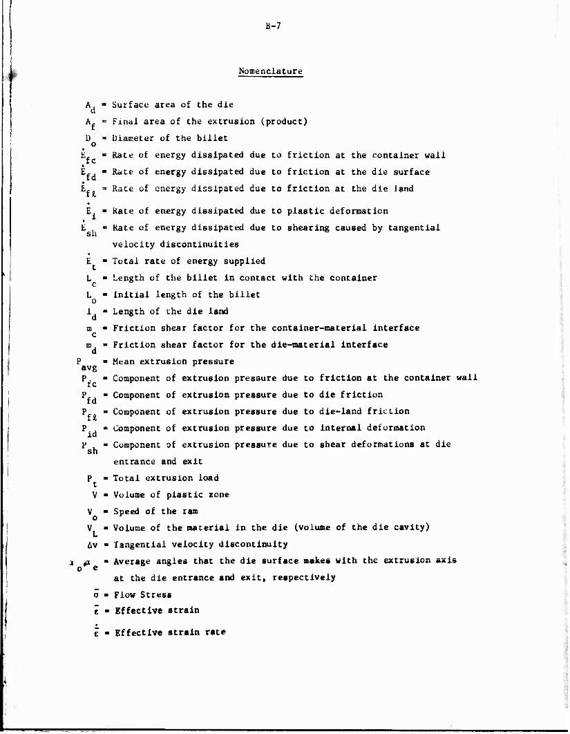
B-7
Nomenclature
ffc
i
hi E,
'sh
avg P. tc
Pfd
Pf*
Pid
Psh
L Av
Surface area of the die
Final area of the extrusion (product)
Diameter of the billet
Rate of energy dissipated due to friction at the container wall
Rate of energy dissipated due to friction at the die surface
Rate of energy dissipated due to friction at the die land
Kate of energy dissipated due to plastic deformation
Rate of energy dissipated due to shearing caused by tangential
velocity discontinuities
Total rate of energy supplied
Length of the billet in contact with the container
Initial length of the billet
Length of the die land
Friction shear factor for the container-material interface
Friction shear factor for the die-material interface
Mean extrusion pressure
Component of extrusion pressure due to friction at the container wall
Component of extrusion pressure due to die friction
Component of extrusion pressure due to die-land friction
Component of extrusion pressure due to internal deformation
Component of extrusion pressure due to shear deformations at die
entrance and exit
Total extrusion load
Volume of plastic zone
Speed of the ram
Volume of the material in the die (volume of the die cavity)
Tangential velocity discontinuity
Average angles that the die surface makes with the extrusion axis
at the die entrance and exit, respectively
Flow Stress
Effective strain
Effective strain rate

APPENDIX C
NUMERICAL CONTROL (NC) MACHINING OF THE EDM ELECTRODE
t

APPENDIX C
NUMERICAL CONTROL (NC) MACHINING OF THE EDM ELECTRODE
This appendix presents the mathematical basis used in calculating
positions of the ball-end milling cutter used for NC machining of the electrode.
The calculation of the cutter paths is done numerically by special FORTRAN
based computer programs developed for this purpose. The system of programs
called SHAPE includes these programs.
To generate a surface by a rotating spherical tool, the tool must
machine the surface in a predetermined fashion. In the present case, the ball-
end mill cutter is moved along the material path lines on the die surface, as
shown in Figure C-l.
To generate the surface of the EDM electrode, the tool position
should be such that the spherical cutting portion of the tool is always normal
to the surface. Thus, to machine an elemental area surrounding a point on
the surface, the coordinates of the tool can be determine^ as follows. A
vector equal to the radius of the ball-end mill is constructed normal to the
elemental area surrounding the point. The coordinates of the end points of
this vector give the position of the center of the cutter, as shown in Figure
C-l.
In our case, the normal vector cannot be determined analytically
since the die surface is defined only as a set of points. Therefore, two
tangential vectors are constructed. The shape of the material path line on
the die surface is known in analytical form. Thus, a vector T which is tan-
gent to any point on a material path lin« is easily determined. The other
tangential vector 1., is determined by taking an average slope of the boundary
of the cross section at chat point. A normal vector n is determined by cross
product of the two vectors T. and T„:
n - fj x I (C-l)
The cutter is moved over the flow lines in a manner shown in
Figure C-l and the coordinates of its center are determined by constructing
the normal vectors at the various points defining the electrode surface. The
detailed mathematics of the procedure, described here, are given in Appendix D.
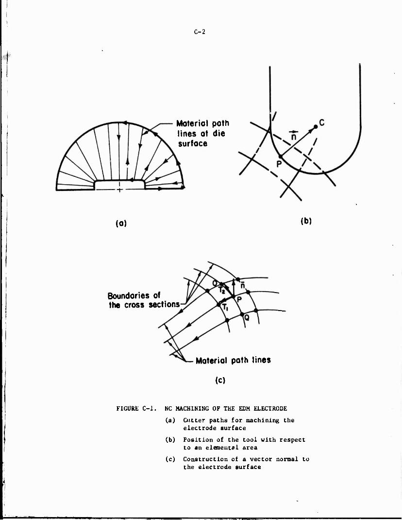
C-2
Material path lines ot die surface
(o) (b)
Boundaries of the cross sections
Material path Sines
(c)
FIGURE C-l. NC MACHINING OF THE EDM ELECTRODE
(a) Cutter paths for machining the electrode surface
(b) Position of the tool with respect to an elemental area
(c) Construction ot a vector normal to the electrode surface

APPENDIX D
DESCRIPTIONS OF GENERAL-PURPOSE COMPUTER PROGRAMS
■MiaMUMiMiti

APPENDIX D
DESCRIPTIONS OF GENERAL-PURPOSE COMPUTER PROGRAMS^
In this appendix, the basis of some of the routines used in the system
of computer programs called "SHAPE" are presented.
Method of Describing Extruded Shapes
The geometry of the extruded structural shapes used for military
applications are relatively simple. In most cases, they are made up of straight-
lines and circular arcs. A convenient method to describe such shapes is to
define them as a polygon and to fit the desired radii at the corners and the
fillets, as seen in Figure D-l.
In the system of computer programs "SHAPE", the center of the billet
is chosen as the origin of the rectangular coordinate system and the coordinates
of the points and associated radii are read in an anti-clockwise manner by sub-
routine REED. Subroutines INTRPL and FITARC fit the arcs at the corner and
fillet points, respectively.
Calculation of the Area oi a Cross Section
The area of any polygon, as shown in Figure D-2, may be obtained
by the formula:
As" 2 {(vrxiy2) * ^w^ + •••+ (Vn-rviyn) + <xiWi>} (D-l)
where x., x2 XR and yJt y^ ..., yn are coordinates of consecutive corners
of the polygon with respect to a Cartesian coordinate system. A convenient
(*) A portion of this Appendix i« based on a prior program, conducted by Batteile's Columbus Laboratories. It Is included here for the sake of completeness.

D-2
(0,0) ?v p7
FIGURE D-l. PROCEDURE FOR REPRESENTING AN EXTRUDED ShAPE
(Only one-half of a symmetrical "T" shape is shown as an example)
V I (X..Y»)
(X..Y.)
2*(X,Yt)
FIGURE D-2. DIAGRAM OF A POLYGON AND A RECTANCULAR COORDINATE SYSTEM DEFINING ITS CORNERS

D-3
Fitting an Arc of a Circle
FITARC is a subroutine to determine the set of points on a specified
arc such that when these points are joined by straight-lines, a fairly smooth
curve is obtained. As shown in Figure D-3, given the coordinates x , y of
the center C, the radius R, the starting angular position, $,, the included b
angle (arc angle), y. and the desired resolution (i.e., the distance between
any two consecutive points on the arc), the subroutine FITARC is programmed
to generate coordinates of points along the desired arc. The arc distance
between any two consecutive points is equal to the specified resolution. A
fillet radius is specified as a positive radius since area due to the fillet
is added to the cross-sectional area and a corner radius is specified as
negative radius, since area due to it is subtracted.
Mathematical Background for Fitting an Arc
The following is a summary of the mathematical derivations used in
programming the subroutine FITARC. All the symbols are defined in Figure D-3,
and the same figure will be referred to, implicitly, throughout this section.
x oxis direction
*i»i • y«♦ i
FIGURE D-3. FITTING A CIRCULAR ARC B5CTWEEN WO INTERSECTING LINES
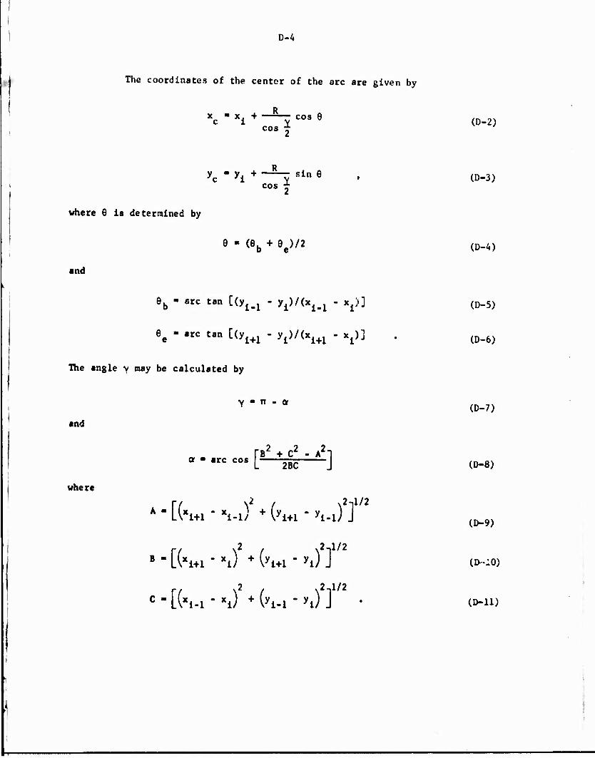
D-4
The coordinates of the center of the arc are given by
Xc - Xi + -H C0S 9 (D-2) cos *
yc " yi + ~H Sin 6 » (D-3) cos *
where 6 is determined by
e - <eb + ee)/2 (D.4)
and
6b - arc tan [(y^ - y^x^ - x^] (D-5)
6e - arc tan [(yi+1 - ^»/(x^ - x^j . (D.6)
The angle v may be calculated by
and
Y ■ TT - or
i?2 ■ -2 *2- or ■ arc cos
where
f"B + C - A*~| L 2BC J
A " [(*i+l " Vl) + (yi+l * yi-l) ] *
(D-7)
(D-8)
(D-9)
B " [(Xi+1 " xi) + (yi+l * yi) J UKLO)
C - [(Xi-1 " Xi) + (yi-l " yi) ] * CD-11)

D-5
and
where
The coordinates of the points e. and b. may be determined by
Xb * xi + l cos 9k
yK ■ y«, + i sin 0, b 'i
X - X + I cos 0 e i e
e i e
I - R tan j
The starting angle of an arc, 9fa, is given
^ - arc tan [fo - yj/^ . XJJ
by
(D-12)
(D-13)
(D-14)
(D-15)
(D-16)
(D-17)
Let
r ■ resolution in thousands of an inch.
n ■ The integer part of [lOOO RY/r + .5]
where n is the number of points that will be determined on the arc. Then
6, the incremental angle, is given by
(D-18)
6-1 n (sign of R)
(D-19)
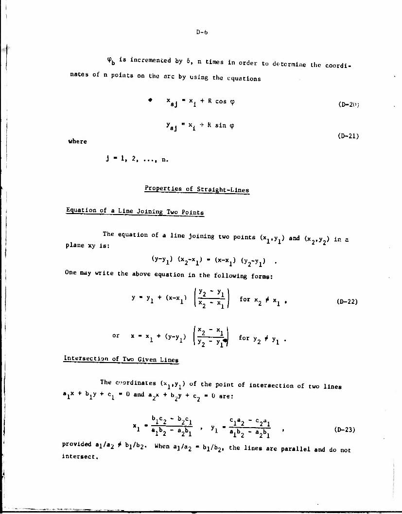
D-fa
<Pb is incremented by 6, n times in order to determine the coordi-
nates of n points on the arc by using the equations
* x - Xj + R cos cp (D-20)
y » x. + R sin cp aJ X (D-21)
where
J - 1, 2, ..., n.
Properties of Straight-Lines
Equation of a Line Joining Two Points
The equation of a line joining two points (x-.y ) and (x~,y2) in s. plane xy is:
Cy-y^ (*2~xi) ■ (*-*!) ^2"yl^ *
One may write the above equation in the following forms:
y ■ y: + (x-x^
or x - x1 + (y-yx)
intersection of Two Given Lines
y2 - y:
x2 - Xj J for x2 * xl » (D-22)
X2-Xll . jpr^ for y2 * yx .
The coordinates (x.,y.) of the point of intersection of two lines a,x + b.y + c, ■ 0 and a.,x + b.,y + c„ ■ 0 are: lli. Ill
blC2 * b2Cl Cla2 " Vl X, - —-, r— . v - —— 1 " »1*2 - «2>1 ' '» * >lh - 'lh " (D"23)
provided a^/a^ j4 bj^/b^. When aj/a^, ■ b|/b>, the lines are parallel and do not Intersect.
•• - - -
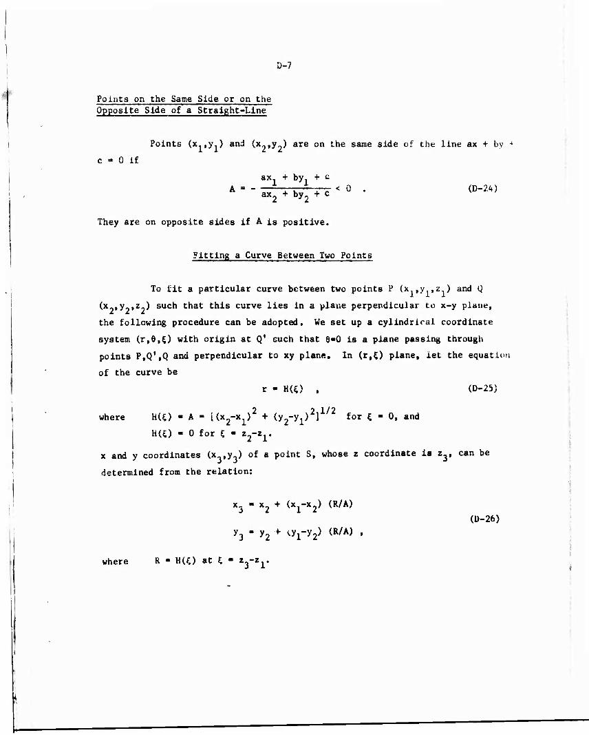
D-7
Points on the Same Side or on the Opposite Side of a Straight-Line
Points (x ,y1) and (x2,y_) are on the same side of the line ax + by 4
c » 0 if
ax + by, + c A ■ - ax2 + by2 H < ö • <D~2*>
They are on opposite sides if A is positive.
Fitting a Curve Between Two Points
To lit a particular curve between two points P (x ,y ,z ) and Q
(x„,y„,z„) such that this curve lies in a plane perpendicular to x-y plane,
the following procedure can be adopted. We set up a cylindrical coordinate
system (r,6,£) with origin at Q' such that 6-0 is a plane passing through
points P,Q',Q and perpendicular to xy plane. In (r.O plane, let the equation
of the curve be
r - H(0 , (D-25)
where H(£) - A - UxfX^2 + (y2-y1>2]1/2 for £ - 0, and
HU) - 0 for 5 - Z2~Z1'
x and y coordinates (x ,y3) of a point S, whose z coordinate is Zy can be
determined from the relation:
x3 - x2 + (x1-x2) (R/A)
y3 - y2 f ^ry2} (R/A) '
(D-26)
where R - HU) at 5 - tfty
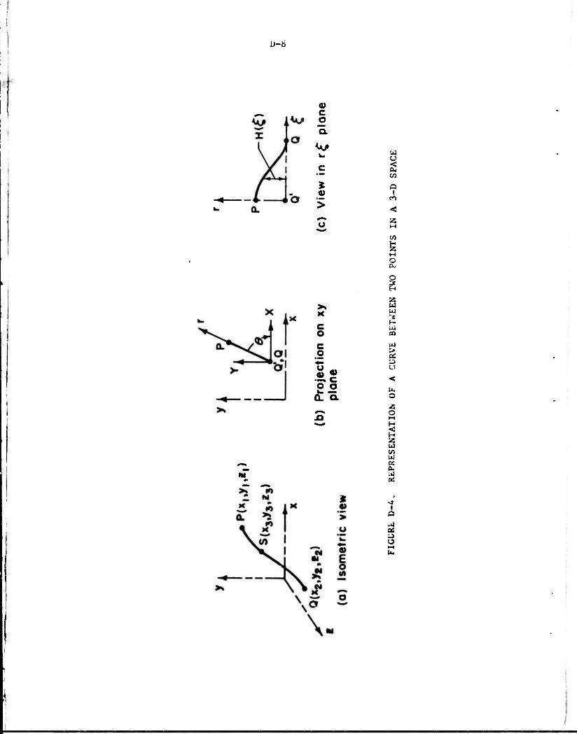
U-ti
C o Q.
>
u u <
p !
en
»
W
c o
« »
22 Q_ a
o a,
s H
S3 W W *i H ui CO
> OS
u
o
o
M
C/5 ui BS a. 2
i
3 o
1

D-9
Polynomial Curve
The polynomial curve which fits the point P and Q is given by:
r = H(5) = A + (CXL2 + 2 C£? - 3A/L2) £2
+ (2A/L3 - 2CXL - 3C2L2) £3 + C^4 + C^5
where L - z_ - z .
Straight-Line
The equation of a straight-line fitted between the points P and Q
is gAven by:
r - H(C) - A (L l Ü .
where y-y2 y2-y1
■ ■ I ■ m ■» »— ■
X~X2 X2~X1
Equation (D-27) may be rewritten in the following form:
x-x - (x -x,) H(OM « l « (D-28)
y-y2 - (y1-y2) H«)/A .
where A is given by Equation (D-25).
. Vector Tangent to Material Path Line
Equation (D-25) represents the equation of a material path line
between points P(x.,y.,z ) ana Q(x ,y ,z ). Substituting for r in terms of
x and y. Equation (D-25) may be written as:
(x-x2)2 + (y-y2)
? - H2(0 , (U-27)

D-10
A vector tangent to a curve is, by definition:
T = (dx/dz)i + (dy/dz)j + k .
Substituting for the aerivations (dx/dz) and (dy/dz):
*1 " A (xi"X2) H'(^ + A (yl'y2} H'(°J + ^ • (!)-29)
where H'(£) - dHU)/d£.
Vector Tangent to a Point on the Boundary of a Die Cross Section
In the numerical definition of the die surface, the boundary of a
die cross section is defined by a number of points. Let P(x.,y.), Q(x2>y2)
and R(x ,y ) be a set of three points. To determine a vector at Q which is
tangent to the boundary, the following procedure is adopted. The angle 6,
which the vector makes with the x axis, is approximated as mein of the angles
0 and 6„, which the lines PQ and QR make with the x axis. Thus,
e if»*-1 \22\ ♦«■-1 (£?)]• (D-W z L 1*3 2/ I 3 2 /J
The tangent vector is given by:
T - t + tan9 j . (D-31)
Vector Normal to Two Vectors
A vector N normal to two vectors t. and $„ is given by the vector
cross product as:
* * * 1 X f2
or Cxt ♦ Cyj + CzK - (AyBz - ArBy) 1 ♦ (A^ - A^) } ♦ (AxBy - AyBx) I .
where f 1 - AxI + AyI + A^ I ■ B i + B 1 + B k
2 x y t
N-cI+c]+Ck. x y z
D-ll
Undercutting by the Tool During Machining of a Surface
In NC machining, the cutter is moved over the surface to be machined
in a specified path. There is a possibility that while machining a particular
portion of the surface, the tool surface may undercut or gouge some other
portion of the surface. Mathematically, it is simple to check for gouging by
a ball-end mill. A spherical tool will cut a surface, if the distances between
the tool center and the points defining the surface are less than the radius of
the tool. Practically, it will be time consuming and very inefficient to check
undercutting over the whole surface for every single position of the tool.
Therefore, the range of the surface over which the possibility of undercutting
is checked for is limited to a small portion of the surface being cut.
In subroutine CHECKNC, ft: each position of the tool, the distance:
between the center of the spherical portion of the tool and a number of points
surrounding the point on the surface being machined are calculated. IT any o<
the distances are found to be less than the radius of the tool, undercutting L-,
predicted and the designer is warned. In interactive mode, the designer can
reduce the size of the ball-end mill to avoid undercutting.

APPENDIX E
SHAPE - A SYSTEM OF PROGRAMS TO ANALYZE THE SHAPE-EXTRUSION PROCESS

APPENDIX E
SHAPE - A SYSTEM OF PROGRAMS TO ANALYZE THE SHAPE-EXTRUSION PROCESS
The computer programs developed to obtain the optimum die shape, to
calculate the extrusion and die pressures, and to obtain coordinate data for
numerical-control machining of the extrusion die are grouped under the name
"SHAPE". This software package can be used either in batch mode, or in inter-
active mode. It is written in FORTRAN-IV language.
Description of SHAPE
SHAPE is written in an overlay structure. As shown in Figure E-l,
it has a main overlay and three primary overlays. Each of these overlays
perform specific functions during the execution of the program.
Overlay (SHAPE,0,0)
This main overlay assigns default values to unspecified variables,
reads values of variables specified by the designer, and controls the othet
overlays. The subroutines in this overlay are all utility routines and are
called by routines in other overlays.
The input of the vt. iables, specified by the designer, is accomplished
via namelist IDATA described in the next section.
Overlay (SHAPE,1,0)
This primary overlay performs the following tasks:
(1) Reads the coordinate data for describing the product
shape.
(2) Fits radii to corner and fillets of the product shape
defined as a polygon.

E-2
o
§ > o
CM
> o
ul > o
X tO CO in to CO tO CO CO
o
z > < M H
a? o z u
S3 o as
(A O a 1 Q U H H H Ok > u
SVlI/lIAUlUllblAlK
3 (AOh
§>-i >n KMAU Ul o ii At u, H r> H Q « 3C < * to to
<U c
3 O u
3 co
CO
§ u 00 o u
«
w
CO
o
o
s H to
to
o
ä 3 H U
H CO
> O
I ui
'J »-- u.

E-3
(3) Moved the shape with respect to the billet center,
if desired.
(4) Defines the die shape as a set of points in 3-D space.
The position of the neutral axis, if not determined numerically, is read via
namelist CTRPTS in this overlay.
Overlay (SHAPE,2,0)
This second primary overlay performs the load calculation. For
given values of extrusion-process variables (specified by Namelist IDATA in
main overlay), the total extrusion pressure and its components, total extru-
sion load and die pressure distribution are determined. In addition, such
parameters as cross-sectional area of the shape, extrusion ratio, perimeter
of the shape, and surface area of the die are computed.
Overlay (SHAPE,3,0)
The third primary overlay calculates the coordinates of the cutter
paths for NC machining of the EDM electrode. The overlay checks for under-
cutting or gouging by the tool. In tta interactive mode, if it is determined
that the specified tool will undercut, the designer is warned and given
the option to change the size of the cutter.
Input by NAMELIST
The input of extrusion-process variables is accomplished by "NAMELIST".
Defining variables as namelist elements gives the flexibility of specifying only
those that are needed. Almost every namelist element is assigned a default
value whenever feasible. Thus, SHAPE will automatically use the default values
of unspecified parameters. When entering a namelist, the first column must be
left blank and a dollar sign must be entered in column two.

E-4
NAMELIST/IDATA
IDATA is read by program SHAPEX. This is used tu read in the
initial values for almost all the variables which the designer may wish to
specify.
Default values for each of the variables listed below are given
at the end of the description in parenthesis.
NAXIAL : Number of divisions in which the length of the
die is divided. This parameter is used in
numerical definition of the die surface and for
subsequent stress analysis (10).
NCURVE : Code to specify the type ot" curve fitted along
assumed path lines (1)
■ 1; polynomial
■ 2; straight line.
Radius of the billet, inch (1.0).
Length of the die, inch (1.0).
Angle defining portion of the die (or extrusion
process) to be analyzed , degree (180.0).
Number of radial divisions in which the die
surface is divided for the purpose of defining
die surface numerically.
Code to specify the material being extruded (8).
- 1 tot titanium alloy T1-6A1-4V.
■ 2 for aluminum alloy Al 7075.
■ 3 for aluminum alloy Al 2017.
- 4 for steel alloy S4337.
* 5 for 99.97Z pure aluminum.
■ b for lead.
■ 7 for OFHC copper.
■ 8 for a perfectly plastic material having a
constant flow stress of 10,000 psi.
1UNIT : Code to specify the category of the extrusion
shape (1).
• 1; rectangular. Tee and similar shapes having
at least one plane of symmetry.
■ 2; shapes with no plane of syotaetrv.
RAD
AL
ANGL1M
NDIV
IMATER

E-5
XMOV.YMOV: Displacement in inches along x and y axis,
respectively, of the extruded shape with respect
to the billet axis (0.0,0.0).
C1,C2 : Coefficients used in the definition of the poly-
nomial curve (0.0,0.0).
NSK1P : Number of extrusion shapes that may be skipped
before reading in the input data on product
shape (0).
RT : Radius of the ball-end mill, inch (0.25).
ALAPPX : An initial guess of the optimal die length, inch (1.0).
LD : Die-land length, inch (0.061).
L0 : Initial length of the billet, inch.
MC : Friction shear factor at material-container
interface (0.2).
MD : Friction shear factor at material-die interface (0.3).
VO: : Ram speed, inch/second (20.).
TEMP : In^ial billet temperature, F (800,0).
The following are logical variables; that is, they are either .TRUE.
or . FALSfc..
DETCTR : If DETCTR - .TRUE., the program will calculate the
position of the neutral axis for IUNIT "1. If
DETCRT - .FALSE., program will read the positions
of the neutral axes via NAMELIST/CTRPTS (.TRUE.).
DEBUG : If DEBUG - .TRUE., values calculated in various
subroutines will be printed for the purpose of
debugging Lhe program (.FALSE.).
OPTLEN : If OPTLEN - .TRUE., the optimal length of the die
is to be determined (.TRUE.).
CHKiNT : If CHKINT - .TRUE., the program checks for under-
cutting by the ball-end mill in machining the
desired surface (.FALSE.).
MANUAL : If MANUAL - .TRUE., the coordinates and the radii
needed to define the shape are entered via TTY
(.FALSE.).

E-6
ANALYS : If ANALYS - .TRUE., the stress analysis is to be
performed (.TRUE.).
DETAIL : If DETAIL - .TRUE., program prints intermediate
results on TAPE1. (.FALSE.).
BATCh : If BATCH = .TRUE., the program will run on batch
mode. If BATCH - .FALSE, the program will run on
interactive mode.
NC : If NC ■ .TRUE., the portion of the computer program
on numerical control (NC) machining of the EDM
electrode will be executed (.TRUE.).
TAPE : If TAPE ■ .TRUE., the coordinates of the ball-end
mill cutter are stored in Tape 3 (.TRUE.).
ISOME'f : If ISOMET - .TRUE., in the interactive mode, an
isometric view of the die surface will be plotted.
NAMELIST/CTRPTS
If the user wishes to specify the positions of the neutral axes
himself instead of determining them, DETCTR is set equal to .FALSE., and the
coordinates of the positions of the neutral axes are entered via NAMELIST/
CTRPTS. XCTR, YCTR are single dimensioned arrays of size 2.
XCTR,YCTR: x and y coordinates, in inches, of the positions
of the neutral axes for the different portions
of the deformation zone (0.0,0.0).
XMOV.YM0V: Displacements, in inches, along x and y axis,
respectively, of the extrusion shape with respect
to the billet axis (0.0,0.0).
Main Overlay - Overlay (0,0)
The program SHAPEX of the main overlay serves essentially as a
coordinating routine which collects the input data and calls other overlays
as necessary. Links between the main overlay and other primary overlays are
maintained through common locations.
E-7
Subroutine ARLA
Purpose: This subroutine calculates the area of a polygon.
Calling Sequence: Call AREA (X,Y,N,A) where X and Y are
single-dimensioned arrays of size N.
Input: X,Y: X and Y coordinates, respectively, of the
corner points of the polygon.
N: Total number of corner points in the polygon.
Output: A: Area of the polygon.
Basis: See Appendix D.
Subroutine AREA2
Purpose: This subroutine calculates the araa of a polygon.
It performs essentially the same calculations as
subroutine AREA; however, it uses a different
calling sequence.
Calling Sequence: Call AREA 2 (X1,Y1,XN,YN,X,Y,K,A) where
X and Y are single-dimensioned arrays of
size K.
Input: XI,Yl: X and Y coordinates, respectively, of the
fiwät point of the polygon.
XN.YN: X and Y coordinates, respectively, of the
last point of the polygon.
X,Y: X and Y coordinates, respectively, of re-
maining K points of the polygon.
Output: A: Area of the polygon.
Basis. See Appendix D.
Subroutine CURVE
Purpose: This subroutine fits the desired curve between two
points (Xj.Y-.Z.) and (X .Y-.Z-), and computes X and
Y coordinates, (XX,YY) of a point on this curve,
whose Z coordinate is ZZ.
E-8
Calling Sequence: Call CURVE (NCODE, X1,Y1,Z1,X2,Y2,Z2,XX,YY,ZZ,
C],C2).
Input: (X1,X2,Y1,Y2,Z1,Z2): X,Y and Z coordinates, respectively,
of the two points between which a curve is to be fitted.
NCODE: Determines the type of curve.
■ 1; polynomial curve.
■ 2; straight-line.
ZZ: Z coordinate of a point on the curve.
C1.C2: Coefficients which vary the shape of the
polynomial curve.
Output: XX,YY: X and Y coordinates, respectively, of a point
on the curve whose Z coordinate is ZZ.
Basis: See Appendix D.
Subroutine XSECTN
Purpose: This subroutine determines points on the die cross
section at various locations along the die lengtn.
Calling Sequences Call XSECTN (NCURVE, NAXIAL, IERR).
Input: NCURVE: Determines the type of curve to be fitted
along material path lines.
■ 1; polynomial curve.
■ 2; straight-line.
NAXIAL: Number of divisions along the axial direction.
Input of other variables is through COMMON
statement.
Output: Output of points on the cross section is via COMMON
statement.
IERR: If > 1, some error occurred in computing the
points on the cross section.
Basis: See Appendix D.

♦ E-9
First Primary Overlay - Overlay (1.0)
The main program in this primary overlay is DIEShP. Along with
other routines, it reads the coordinate data describing the extrusion shape,
fits the radii at the corners and fillets, moves the shape with respect to
the extrusion axis. Further, DIESHP determines the position of the neutral axis
if desired, computes the positions of the end points on the material
path lines, fits the curves between end points of the material path lines and
defines the shape of the die as a set of points in a three-dimensional space.
Subroutine REED
Purpose: This subroutine reads the input data on the radii and
coordinates of the points defining the extrusion shape.
Calling Sequence; Call REED (X,Y,R,NIP,IERR,MANUAL,BATCH), where
X,Y and R are single-dimensioned arrays of
size 50.
Input: X,Y: X and Y coordinates, respectively, of the points
defining the extrusion shape.
R: Radius to be fitted at each corner or fillet to
form the shape.
MANUAL: If MANUAL - .TRUE., the data (X,Y,R) are entered
*•<« TTY.
BATCH: If BATCH - .TRUE., the data (X.Y.R) are read
from TAPE 2.
Output: NIP: Number of points that were read.
IERR: > 1 if an error occurred in reading the input data.
Basis: See Appendix D.
Subroutine SOLVE
Purpose: This subroutine finds the solution of an Equation F(x) • 0.,
within a specified range of x.
Calling Sequence: Call SOLVE (F,XLOW,XHIGH,LIMITX,LIMITF,XSOLVE,IESR).
E-10
InjKJt: F: User's specified external function F(x). x is a
dummy variable.
XH1GH.XL0W: Limits of the range of the independent
variable x, within which a solution is
sought.
LIMITF: Admissible inaccuracy in the solution of
equation F(x) - 0. Solution is considered
obtained when ABS(F(x)) < LIMITF.
LIMITX: Admissible inaccuracy in the value of XSOLVE.
Output: XSOLVE: The value of independent variable x which
solves the equation.
IERR: - 1 when XSOLVE is obtained within the pre-
scribed range of variable x.
> 1 if some error occurred and a solution was
not obtained.
Basis: The subroutine uses the method of interval halving to
find the solution. Reference (13) describes in detail
this method.
Subroutine CTRPT
Purpose: This subroutine determines the position of the neutral
axis.
Calling Sequence: Call CTRPT (IERR).
Input: Input of variables Is through COMMON statement. RATIO
is used as an EXTERNAL function in the subroutine.
Output: XC: x coordinate of the neutral axis.
YC: y coordinate of the neutral axis.
IERR: If > 1, error occurred in calculating XC or YC.
Output of XC and YC Is through COMMON statement.
Basis: See Appendix A.
'
—».

E-ll
Subroutine RANGE
Purpose: This subroutine determines the maximum and minimum values
among an array of real numbers.
Calling Sequence: Call RANGE (Z,N,ZMIN,ZMAX)
Input: Z: A single dimensioned array of real numbers.
N: Size of the array.
Output: ZMIN: Minimum value among Z.
ZMAX: Maximum value among Z.
Function RATIOX(X)
Purpose: In conjunction with subroutine CTRPT, this function
calculates the x coordinate of the neutral axis.
Input: X- Chosen position of the neutral axis along x axis.
Input of other variables is through COMMON statements.
Output: RATIOX: The difference between the overall area reduction
and the area reduction in the portion of the
deformation zone on one side of plane x - x.
Basis: See Appendix A.
Function RATIOYQf)
Purpose: In conjunction with subroutine CTRPT, this function
calculates the y coordinate of the neutral axis.
Input: Y: Chosen position of the neutral aria along y axis.
Input of other variables Is through COMMON statement«.
Output: RATIOY: The difference between the overall area reduction
and the area reduction in the portion of the
deformation zone on one side of the plane y • y.
Basis: See Appendix A.

E-12
Subroutine PAThPT
Purpose; This subroutine calculates the end point of a material
path line on the boundary of the exit cross section.
Calling Sequence; Call PATKPT (AREAB.XSS.YSS,IERR).
Input; AREAB - Area of a portion of the billet cross section.
Input of other variables is through COMMON
statements. ELAREA is used as EXTERNAL FUNCTION
in the subroutine.
Output; XSS,YSS: X and Y coordinates, respectively, of the end
point.
IERR: If > 1, error occurred in calculating XSS or
YSS.
Basis; See Appendix A.
Function ELAREA (Z)
Purpose: For a given x or y coordinate of a point on the exit
boundary, this function determines the difference in
overall area reduction (A,/A ) and the area reduction i o
of an element of the initial billet cross section.
Together with subroutine PATHPT, it determines the end
point of a material path line on the exit boundary.
Input; Z: x or y coordinate of the assumed end point of the
material path line. Input of other variables is
through COMMON statement.
Output: ELAREA: The difference in overall area reduction
and the area reduction of an element of the
billet cross section.
Basis: See Appendix A.
HW
E-13
Subroutine ERRPOT
Purpose; This subroutine prints on the output device any
errors that occur during the execution of the program
DIESHP.
Calling Sequence; Call ERRPOT (IERR).
Input; IERR: If > 1, error «purred. Depending on the value
of IERR, the information on the nature of the
error is printed on the output device.
Subroutine INTRPL
Purpose: For a polygonal cross section defined by a series of
fillet or corner coordinates and the associated radii,
this subroutine calculates the points which actually
lie on the perimeter of the cross section.
Calling Sequence: Call INTRPL (XPLOT,ZPLOT,NPLOT,XPS.ZPS,RPS,IPS),
where XPLOT and ZPLOT are single-dimensioned
arrays of size NPLOT; XPS.ZPS and RPS are single-
dimensioned arrays of size IPS.
Input: XPS.ZPS: x and y coordinates, respectively, of the points
defining the polygonal cross section.
RPS: Radii at fillets or corners of the polygonal
cross section.
IPS: Number of corner and fillet points.
Output: XPLOT,ZPLOT: x and y coordinates of points on the
perimeter of the cross section.
NPLOT: Number of such points.

E-1A
Subroutine FITARC
Purpose; Given three points and a radius, this subroutine defines
a certain number of equispaced points on an arc tangent
to the two lines defined by the three points.
Calling Sequence; Call FITARC (Xl,Zl,X2,Z2,X3,Z3,RD,XP,ZP,NP,Rt:S,
L1M.IFLAG), where XP and ZP are single-dimensioned
arrays of size NP.
Input; (XI,Zl), (X2.Z2), (X3.Z3): coordinates (x,y) of the three
points.
RD: Radius of the arc to be fitted.
RES: Resolution or distance between the points on the arc.
LIM: Maximum allowable number of points on the fitted arc.
IFLAG: If - 1, actual number of points did not exceed LIM.
If >^ 1, actual number exceeded LIM.
XP,ZP: Coordinates (x and y) of points on the arc.
NP: Actual number of such points.
Subroutine DIEPIC
Purpose: Plots the shapes of the billet and the product, material
path lines, and die cross sections on CRT display screen.
This routine uses other routines of the IGS package and
is hardware dependent.
Subroutine ISOVIEW
Purpose: Draws an lsomatric view of the die shape. This routine
also uses other standard routines of the IGS package. It
is also hardware dependent.
Subroutine POSIT
Purpose; This subroutine Is used to position any writing on CRT
display screen.
■

E-15
Second Primary Overlay - Overlay (2.0)
The main program of this primary overlay is ANALY. Along with
other routines, ANALY calculates the extrusion pressure, optimal length
of the die and mean-die pressure distribution. In interactive mode, a
plot of extrusion pressure versus die length is drawn.
Subroutine SLAB
Purpose; This routine computes the various components of the
extrusion pressure and the total extrusion pressure.
Input and Output : Is through common locations.
Basis: See Appendix B.
Subroutine OUTPT
Purpose: This routine writes the input and output information
concerning the load calculation.
Subroutine PPLOT
Purpose: This routine is used in the interactive mode to plot the
maximum extrusion pressure as function of the die length.
It uses other routines of IGS package and is hardware
dependent.
Calling Sequence; Call PPLOT (XM1N,YM1N,XMAX,YMAX,ANSWER).
Input: (XMIN.YMIN): Coordinates defining the size of the subject
UMAX, MAX) space> Other input is through common
locations.
Output: ANSWER: If ANSWER - YES, the designer selects the optimal
length of th« die. Other output is through
common locations.
i
Subroutine MATERL
Purpose: In conjunction with the subroutines T1-6A1-4V, AL2075,
AL2017, S4337, ALUMSP, LEAD, OFHC, and ALOYSP, it

f E-16
calculates the flow stress of the desired material
as a function of the temperature, strain, and strain
rate.
Input; IMATER: Code to specify the material bei.g extruded.
- 1 for titanium alloy T1-6A1-4V.
■ 2 for aluminum alloy AL7075.
■ 3 for aluminum alloy AL2017.
- 4 for steel alloy S4337.
■ 5 for 99.97% pure aluminum.
■ 6 for lead.
- 7 for OFHC copper.
■ 8 for a perfectly plastic material having
a constant flow stress of 10,000 psi.
TEMP: Initial temperature of extrusion.
STRAIN: Value of effective strain at which the flow
stress is to be determined.
STRRAT: Value of strain rate.
Output: FSTRES: Flow stress of the material.
Subroutine AL7075
Purpose: Flow stress data for aluminum alloy AL7075 at various
temperatures and different strain values are stored in
this routine and is called whenever flow stress data
for AL7075 is required at a particular combination of
•train and temperature.
Function FSTRS
Purpose: This function routine performs the interpolation in
determining the values of m and c in flow stress
calculation. (Flow stress is defined as function of
■train, strain rate and temperature in terms of the
coefficients m and c). To interpolate the data for
correct temperature value, library subroutli-e AITKK
is used.

E-17
I Subroutine SLOPL
Purpose: This subroutine is used to determine slopes of the
material path lines at the entrance and the exit of
the die.
Input: NCODL: Code to define the type of curve fitted
between the end points of the material path
line.
(X1,Y1,Z1): (x,y,z) coordinates of the end points (X2.Y2.Z2) . fc. .,,.,, of the material path line.
N2: N2 = 2 is always used.
C1,C2: Coefficients of the polynomial curve.
Output: HDZ: Slopes of the path lines at the die entrance
and the die exit.
Function SURF
Purpose: This function calculates the area of a triangle. It
is used in calculating friction at the die surface.
(X1,Y1,Z1): Cjrner points of the triangle. (X2.Y2.Z2) (X3.Y3.Z3)
Third Pvimary Cverlay - Overlay (3.0)
DJLNC is the m^in program of this overlay. It determines the cutter
path for NC machining of t.UI electrodes. Using other routines, It computes
the coordinates of the poaitic:* of the cutter as the cutter is moved over the
die surface in a predetermined manner. The position of the cutter ia calcu-
lated by constructing a vttct J/ normal to the surface from two tangent vectors.
OIEMC also checks for any undercutting by the tool.

E-18
# Subroutine CUTVLC
Purpose; This routine computes vectors normal to the die surface
along a material path line. It uses other routines of
the overlay. RX,RY,RZ are single-dimensioned arrays of
size 22.
Calling Sequence; CUTVEC (NC0DE,N2,N1,RX,RY,K2,I).
Input; NCODE: Code to specify the curve fitted between the
material end points.
N2: Number of points defining the die surface along
a material path line.
Nl: Number of points defining the die surface along
a cross-sectional boundary.
I: Number specifying the material path line.
Other input is via common locations.
Output; (RX,RY,RZ): (x,y,z) components of the normal vectors.
Basis; See Appendix L).
Subroutine TNGNTA
Purpose; This subroutine determines tangent vector at points along
a material path line.
Calling Sequence; Call TNGNTA (NCODE,XI,Y1,Z1,X2,Y2,Z2,N2,C1.C2,
AX.AY.AZ).
Input; NCODE: Code specifying the curve fitted between material
path points.
(X1.Y1.Z1): (x,y,z) coordinates of the end points of a (X2.t2.Z2) MterU1 path Une#
N2: Number of points along a material path curve.
C1,C2: Coefficients of the puiynualal curve.
Output: (AX.AY.AZ): (x.y.z) compon nts of the tangent vectors.
AX,AY and AZ are single-dimensioned arrays
of size N2.
Basis: See Appendix D.

E-19
Subroutine TANV
Purpose; Given thrtie points on the boundary of a cross-sectional
plane, a vector tangent to the middle point is constructed.
Calling Sequence: Call TANV (X1,Y1,X2,Y2,X3,Y3,BX,BY).
Input: (XI,Yl): (x,y) coordinates of the three points on the (X2 Y2) . '.',.: cross-sectional boundary. VAJ t iJ)
(BX,8Y): (x,y) components of the tangent vector.
Basis: See Appendix D.
Subroutine NORV
Purpose: This subroutine calculates a vector normal to two vectors
using vector cross product.
Calling Sequence: Call NORV (AX,AY,AZ,BX,BY,BZ,RX,RY,RZ>
Input: (AX.AY.AZ): (x,y,z) components of the two vectors. (BX.BY.BZ)
Output: (RX.RY.RZ): (x,y,z) components of the normal vector.
Basis: See Appendix D.
Subroutine IGSINT
Purpose: This routine initializes the IGS package system. It is
hardware dependent.
Subroutine PLOT
Purpose: This is used to plot the cutter paths on CRT screen.
It Is also hardware dependent.
Subroutine VIEUCH
Purpose: This is used to change the angle of the isometric plot
of the cutter path.

F-20
Subroutine CHLCKNC
Purpose; For given tool position, this routine checks if the tool
will undercut the surrounding die s,urface. If under-
cutting is detected, the designer is warned and is. given
the option to change the size of the cutter.
Calling Sequence: CalJ CHLCKNC (I,J,XCUT,YCUI,ZCUT,N1,N2,N,KERR,
ThETA).
Input: I,J: Specify the point on the die surface.
XCUT,YCUT,ZCUT: Coordinates of the position of the cutter.
N1,N2: Number of points along the cross-sectional boundary
and material path curve respectively.
N: N is related to the number of surrounding points at
which the undercutting is checked.
K.ERR: Number used tc control the execution of the subroutine.
THETA: Angle of the isometric view of the cutter path. Other
input is via the common locations.
Output: KERR: Nuaber used to control the execution of program D1LNC.
Basis: See Appendix D.
f
APPENDIX F
MANUFACTURE OF EXTRUSION DIES
APPENDIX F
MANUFACTURE OF EXTRUSION DIES
This appendix gives the detailed dimensions and the procedure used
in manufacturing the dies for the extrusion trials. For extruding round
and rectangular shapes, three different dies were made. Figures F-l to F-3
show Lhe shapes and dimensions of these dies.
Streamlined Die - D3
This die was used to extrude a rectangular shape from a cylindrical
billet. Computer-aided design and computer-aided manufacturing (CAD/CAM)
techniques, developed in this project, were utilized to design and manufacture
this die.
The first step in the design of this die was the selection of die
height (or length). Since the optimum die configuration depends on the flow
stress of the material being extruded, three different optimal die lengths
were obtained from the computer program "SHAPE" corresponding to the three
materials (Cu 110, Al 6063, Al 7075) extruded through thip die. A length
of 1.158 Inches was selected as a compromise of the three optimal lengths.
Next, the die surface and the cutter path for NC (Numerical Control)
machining of the EDM electrode were determined from SHAPE. In the input data,
the dimensions of the billet and the rectangular shape were reduced by 0.003
inch/linear dimension to accomodate EDM allowance.
The data on coordinates of the cutter path were used by the post-
processor to generate the NC tape, which is then used to machine the graphite
EDM electrode seen in Figure 3-12a.
The die block was machined from hot-work die steel, heat treated
to proper hardness and then ground on outside diameter and faces. The graphite
electrode was then sunk in the die block to machine the die surface bv EDM
process. Polishing of the die surface was done by hand. Figure 3-11 shows th<
die made by this process.

F-2
Section B-B
FIGURE F-l. STREAMLINED ME - I>3 FOR EXTRUDING A RECTANGULAR SHAPE FROM ROUND BTU.RT
(Hsat treated to R 43-4* , Material Ml. H12, or H13)C
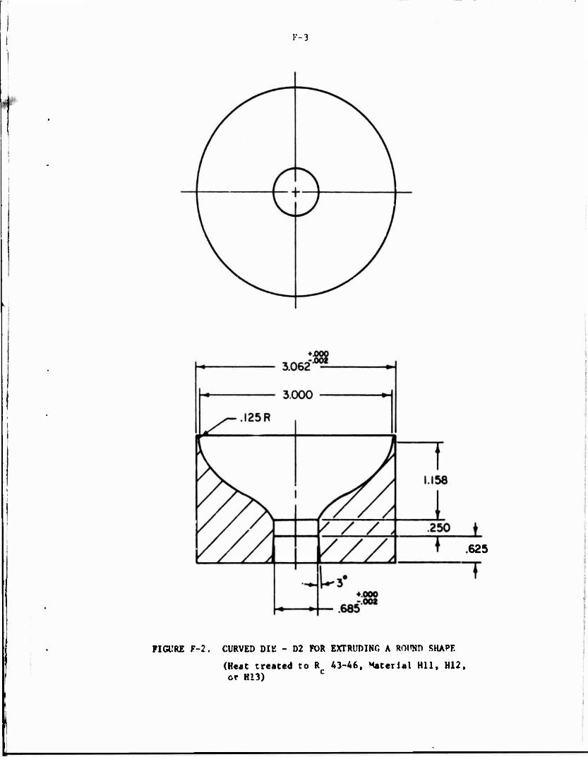
F-3
625
FIGURE F-2. CURVED DIE - D2 FOR EXTRUDING A ROWD SHAPE
(Heat created to R 43-46, Material Hll, H12, or H13)

F-4
B -«n
Section A-A
FIGURE F-3. FLAT-FACE DIE - Dl FAR EXTRUMNO A RF.rTAWHLAR SHAPE FROM A ROUND BILLET
(Heat treated to R 43-46, Material Mil, F12, or "1"*) c
F-5
Curved Die - 1)2
To make a fair comparison of extrusion loads for extruding round and
rectangular shapes, the length of the die, D2, for the round shape was kept
the same as that of streamlined die, D3, for the rectangular shape. The die
surface was chosen to be of polynomial form with zero entrance and exit angles
(see Appendix D, page D-9). The coefficients C. and C- of the polynomial curve,
were taken to be zero, since the study on extrusion of an elliptic shape had
shown that the extrusion load is only slightly affected bv these coefficients.
To machine the die surface by copy turning, a special template was
NC machined. The die was machined by copy turning to final dimensions. The
die was then heat treated and ground on outside diameter, Inside diameter and
flat faces. Finally, the die surface was polished by hand. Figure 3-12 shows
the finished die.
Flat-Faced Die - Dl
As seen in Figure F-3, the width of the die land of the flat-faced
die is designed to obtain a uniform metal flow at the exit. The relative
dimensions of the die land were calculated using the relation:
I P A
l2 Al *2
where £., P., A. ■ effective land width, perimeter and cross section.i]
area, respectively, of the portion "i" of the die
cavity.
The die block was turned, heat treated, and then ground on OD and
faces. The die cavity was sunk by special EDM electrodes from front and back
to give the desired die cavity and die-land configuration. The die laiv1 was
polished by hand.

s t E
E w
a - U O
Ee V. H
;,1>
li I — m 3 3
3 £ 3 Ä -. 6 -
| C w « 5 w I C 3 M - -. - . Ü 0 »J c < .>- i
I i. ~ 0
a - ,-■ * ■.,■ 0 M u Ä — ~i > ft -0 ft C I -o > - *• c
-19 ° 5 7 3 * -
5 8
If
H if
fEI
* r. B •-
F*
lit ■ceo« 0
« ft > i T> (■ 3
w C
!?!
SB
.'S ■ 0 "
12
u b H £ v a • o c o i» - »- > u ^ 9
f l.fS! sr;>I: " S S *
•; * * * 0- 3 .. .i- ■ c ■ i « ■ill's" £ C i. | < C W < ft * L» Ö
5 .i J f l u £ ft. * ft —
TT t- I- - - c ■ m -■ >- <-
• O 3 0 R * *-'•■
• — * £ • < • * • X
a M
si
S>J;IS ■ H ft
■ II 3 W II
ilJ
I M — 1 /
C k » o — Ft « K
3 •: -5 - ./ k. (J «- 1« Ox u * o - a I • «- <
&.■.-: r j 0 J- w H --■ ■: s *",
e | S - J -S3" S j 3 * -
• x: i i
n *- -
Si
» fj if t! < ^
IS
I si i" i| «5
Si
; i s - ' .8 i
— ^ H -0 * 0 X U
*> K « tj C V - 3
3 « i
3 V r. _ kl F I * I - .- t | • ; r i i k i
Ja
< 3 ^
I- » - C
■« C —
n m m
S w - e *■
■ T t * > „
I 3 J e i u it a- - •■ -
.^».;:
• e a 6
i-f C l * — ^ „ -
g .- He
5 i I
i i j ! 15
\ i ' I!
Si
- - - - •
r
. l'!f Is ij !
}i if HI I m
St e * r "
a ; •.. 3 »t i - 9 »•!§- ft. * I • w
it]-1
i'rJ'xi ■Js-T'i
L*|! i Hifi! III1!!
ill!«
«{njj Ulli
s I i
si .".£ St 3'-
1 j i
:•
iljii] - . - •
i :e ? «1
i.
ü ü \h i H i if si pi : i, 1
li II .33 I fs :
1 5 * _ s r s'
i i ■!i 3
4 t J * ~ ft t I V
»* * -
ist-» *i.-s |
t s i f - s
nah V* ! »si!?: i9H3l
!{»e2l
n\U - • •

■■■■■■•■■■■ .,*S-;J^>(K,*J-.T.-SK".-»;
US ARMY AVIATION SYSTEMS COMMAND
DISTRIBUTION LIST
No. of Copies To
Commander, US Army Aviation Systems Command, P.O. Box 209, St. Louis, Missouri 63166
10 ATTN: AMSAV-EXT 1 AMSAV-FE (Cliff Sims, Maint Engr) 1 AMSAV-EQ (C. Crawford, Sys Dev 6 Qual) 1 AMSAV-FES (H. Bull, Corpus Christi) 2 AMSAV-ZDR (Ref Library)
Project Manager, Advanced Attack Helicopter, P.O. Box 209, St. Louis, Missouri 63U6
1 ATTN: AMCPM-ÄAH, TM
Project Manager, Utility Tactical Transport Aircraft System, P.O. Box 209, St. Louis, Missouri 63166
1 ATTN: AMCPM-UA-T
Project Manager, CH-47 Modernization, P.O. Box 209, St. Louis, Missouri 63166
1 ATTN: AMCPM-CH47M
Project Manager, Advanced Scout Helicopter, P.O. Box 209, St. Louis, Missouri 63166
1 ATTN: AMSAV-SIA
Project Manager, Aircraft Survivability Equipment, P.O. Box 209, St. Louis, Missouri 63166
1 ATTN: AMCPM-ASE-TM
Project Manager, Cobra, P.O. Box 209, St. Louis, Missouri 63166 1 ATTN: AMCPM-CO-T
Project Manager, Iranian Aircraft Program, P.O. Box 209, St. Louis, Missouri 63166
1 ATTN: AMCPM-IAP-T
Commander, US Army Materiel Command, S001 Eisenhower Avenue, Alexandria, Virginia 22333
4 ATTN: AMCRD-TE
Director, Eustis Directorate, US Army Air Mobility RfiD Lab, Ft. Eustis, Virginia 23604
1 ATTN: SAVDL-EU-TAS
Director, Ames Directorate, US Army Air Mobility RID Lab, Ames Research Center, Moffett Field, California 94035
1 ATTN: SAVDL-AM
,

No. of Copies To
Director, Langley Directorate, US Army Air Mobility R$D Lab, Mail Stop 266, Hampton, Virginia 23365
1 ATTN: SAVDL-LA
Director, Lewis Directorate, US Army Air Mobility R$D Lab, 21000 Brook Park Rd, Cleveland, Ohio 44135
1 ATTN: SAVDL-LE
Director, Production Equipment Agency, Rock Island Arsenal, Rock Island, Illinois 61201
1 ATTN: AMXPE-MT
Air Force Materials Laboratory, Manufacturing Technology Division Wright-Patterson Air Force Base, Ohio 45433
1 ATTN: AFML/LTM 1 AFML/LTN 1 AFML/LTE
Commander, US Army Electronics Command, Ft. Monmouth, New Jersey 07703 1 ATTN: AMS5L-RD-P
Commander, US Army Missile Command, Redstone Arsenal, Alabama 35809 1 ATTN: AMSMI-IIE
Commander, US Army Troop Support Command, 4300 Goodfellow Blvd., St. Louis, Missouri 63120
1 ATTN: AMSTS-PLC
Commander, US Army Armament Command, Rock Island, Illinois 61201 1 ATTN: AMSAR-PPR-1W
Commander, US Army Tank-Automotive Command, Warren, Michigan 48090 1 ATTN: AMSTA-RCM.l
12 Commander, Defense Documentation Center, Cameron Station, Building 5, 5010 Duke Street, Alexandria, Virginia 22314
Hughes Helicopter, Division of Summa Corporation, M/S T-419, Centinella Avenue and Teale Street, Culver City, California 90230
2 ATTN: Mr. R. E. Moore, Bldg. 314
Sikorsky Aircraft Division, United Aircraft Corporation, Stratford, Connecticut 06497
2 ATTN: Mr. Stan Silverstein, Section Supv., Manufacturing Technology
Bell Helicopter Company, P.O. Box 482, Ft. Worth, Texas 76101 2 ATTN: Mr. P. Baumgartner, Chief, Manufacturing Technology
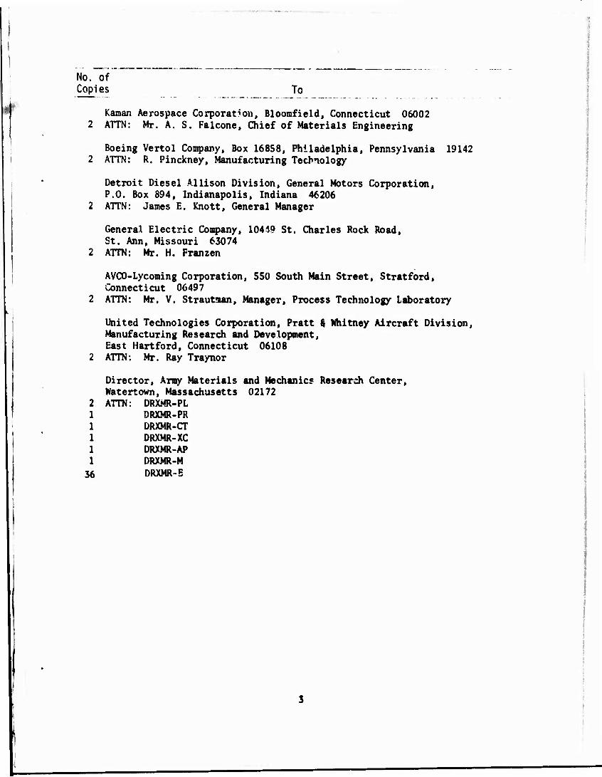
No. of Copies To
Kaman Aerospace Corporation, Bloomfield, Connecticut 06002 ATTN: Mr. A. S. Falcone, Chief of Materials Engineering
Boeing Vertol Company, Box 16858, Philadelphia, Pennsylvania 19142 ATTN: R. Pinckney, Manufacturing Technology
Detroit Diesel Allison Division, General Motors Corporation, P.O. Box 894, Indianapolis, Indiana 46206 ATTN: James E. Knott, General Manager
General Electric Company, 10449 St. Charles Rock Road, St. Ann, Missouri 63074 ATTN: Mr. H. Franzen
36
AVCO-Lycoming Corporation, 550 South Main Street, Stratford, Connecticut 06497 ATTN: Mr. V. Strautaan, Manager, Process Technology Laboratory
United Technologies Corporation, Pratt $ Whitney Aircraft Division, Manufacturing Research and Development, East Hartford, Connecticut 06108 ATTN: Mr. Ray Traynor
Director, Army Materials and Mechanic« Research Center, Watertown, Massachusetts 02172 ATTN: DRXMR-PL
DRXMR-PR DRXMR-CT DRXMR-XC DRXMR-AP DRXMR-M DRXMR-E
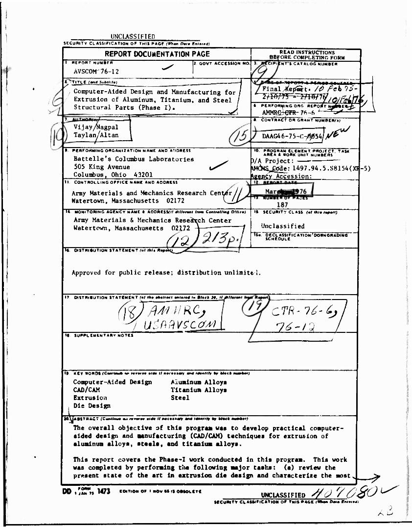
UNCLASSIFIED SECURITY CLASSIFICATION OF THIS PAGF (Whm Dm Fnfrrd)
t. TITLE (and Subllil,)
REPORT DOCUMENTATION PAGE I REPORTNUMBFR
AVSCOM'76-12 2 GOVT ACCESSION NO ORIENT'S CATALOG NUMBER
Computer-Aided Design and Manufacturing for Extrusion cf Aluminum, Titanium, and Steel Structural Parts (Phase I).
Vijay^agpal TayIan/Altan I OS
• PERFORMING ORGANIZATION NAME AND ADDRESS
Battelle's Columbus Laboratories 505 King Avenue Columbus, Ohio 43201
H CONTROLLING OFFICE NAME AND AOORESS
READ INSTRUCTIONS BEFORE COMPLETING FORM
■ ntimi raufcnri» nal/!(ep«t. /<& feb IS
6 PERFORMING ORG REPORT WHEli.
AMMRer^R-76-r» -**- • CONTRACT OR GRANT NUMBERf»
DAAG46-75-C7^54 l$s*u/
10. PROGRAM ELEMENT PROJfCT TAS«f AREA • WORK UNIT NUMBERS
)/A Project: ■ WCMS^ode: 1497.94.5.S8154(XI Vyency Accession:
Army Materials and Mechanics Research Center// Watertown, Massachusetts 02172 \^Lr
Ti MONITORING AGENCY NAME 1 AOORESSf" dllltnxl Inm Controlling Ollirm)
Army Materials & Mechanics Resedreh Center Watertown, Massachusetts 02172 \—-—" 1
I« DISTRIBUTION STATEMENT (ol IM. *«p •VL_^-
-5)
It. SECURITY CLASS (ol ihi. »pon;
Unclassified TiS. OECLASSIFICATION'OOWNGNAOING
SCHEDULE
Approved for public release; distribution unlimite 1.
IT DISTRIBUTION STATEMENT (ol tho itilivf mnltio4 I» Blatk 7«. II 0lltm>l
-7 UibPiVStcfM •• SUPPLEMLNT*«v NOTES
ZTR- 76- 6j
•• KEY SOROS ICMIIWI «• «•••'•• «id* I« ■•••••an w>4 Hotnl, *r U»(t m—t»Q
Aluminum Alloys Titanium Alloy« Steel
xe
Computer-Aided Design CAD/CAM Extrusion Die Design
The overall objective of this prograa was to develop prsctlcal computer- sided design and manufacturing (CAD/CAM) techniques for extrusion of aluminum alloys, stasis, and titanium alloys.
This report covers the Phase-I work conducted In this program. This work was completed by performing the following major tasks: (s) review the present stste of the srt In extrusion dls design and characterise the most
00 l '?»"»• 1473 IMTIOMOF ' NOW II •} OBSOLETE UNCLASSIFIED S/<J /£/<fCs — SECuBlTV CLASSIFICATION OF TMIf PAGE fl i t>0lm t'.tt—J
AZ

■ ■■ ■
UNCLASSIFIED tfCUWlTV CLAWnOTlQH Of THIS PHOlfWhrn Omm M*tv4)
& commonly used extruded shapes, (b) divide these shapes Into geometric nodules and develop the CAD/CAM techniques for extruding a modular shape, (c) expand the results of the analysis, developed for a modular shape, to more practical simple shapes, such as L's, T's, and rectangles, and (d) perform extrusion trials with a rectangular shape to demonstrate the validity of CAD/GAM techniques.
In order to enhance readability, the results of Phase-I work are presented in the form of three chapters as follows: (1) Die Design for Extrusion of Structural Shapes, (2) CAD/CAM of a Streamlined Die for a Modular Shape, (3) CAD/CAM of Streamlined Dies for Lubricated Extrusion of Simple Struc- tural Shapes.
1
UNCLASSIFIED KCWMTV CkAMlttCATlON Of TM« MllUti« Dm» ***m+m
Related Documents