Computational Modeling of Residual Stress Formation during the Electron Beam Melting Process for Inconel 718 P. Prabhakar 1a , W.J. Sames b , R. Smith c , R. Dehoff d , and S.S. Babu c,d a Department of Mechanical Engineering, University of Texas, El Paso, TX b Department of Nuclear Engineering, Texas A&M University, College Station, TX c Department of Aerospace and Biomedical Engineering, University of Tennessee, Knoxville, TN d Manufacturing Demonstration Facility, Oak Ridge National Laboratory, Knoxville, TN Abstract A computational modeling approach to simulate residual stress formation during the Electron Beam Melting (EBM) process within the Additive Manufacturing (AM) tech- nologies for Inconel 718 is presented in this paper. The EBM process has demonstrated a high potential to fabricate components with complex geometries, but the resulting components are influenced by the thermal cycles observed during the manufacturing process. When processing nickel based superalloys, very high temperatures (approx. 1000 C) are observed in the powder bed, base plate, and build. These high temper- atures, when combined with substrate adherence, can result in warping of the base plate and affect the final component by causing defects. It is important to have an understanding of the thermo-mechanical response of the entire system, that is, its me- chanical behavior towards thermal loading occurring during the EBM process prior to manufacturing a component. Therefore, computational models to predict the response of the system during the EBM process will aid in eliminating the undesired process conditions, a-priori, in order to fabricate the optimum component. Such a comprehen- sive computational modeling approach demonstrated to analyze the warping of the base plate, stress and plastic strain accumulation within the material, and thermal cycles in the system during different stages of the EBM process. Preprint submitted to Additive Manufacturing November 20, 2014

Welcome message from author
This document is posted to help you gain knowledge. Please leave a comment to let me know what you think about it! Share it to your friends and learn new things together.
Transcript
Computational Modeling of Residual Stress Formation during
the Electron Beam Melting Process for Inconel 718
P. Prabhakar 1a, W.J. Samesb, R. Smithc, R. Dehoffd, and S.S. Babuc,d
aDepartment of Mechanical Engineering, University of Texas, El Paso, TXbDepartment of Nuclear Engineering, Texas A&M University, College Station, TX
cDepartment of Aerospace and Biomedical Engineering, University of Tennessee, Knoxville, TNdManufacturing Demonstration Facility, Oak Ridge National Laboratory, Knoxville, TN
Abstract
A computational modeling approach to simulate residual stress formation during the
Electron Beam Melting (EBM) process within the Additive Manufacturing (AM) tech-
nologies for Inconel 718 is presented in this paper. The EBM process has demonstrated
a high potential to fabricate components with complex geometries, but the resulting
components are influenced by the thermal cycles observed during the manufacturing
process. When processing nickel based superalloys, very high temperatures (approx.
1000 C) are observed in the powder bed, base plate, and build. These high temper-
atures, when combined with substrate adherence, can result in warping of the base
plate and affect the final component by causing defects. It is important to have an
understanding of the thermo-mechanical response of the entire system, that is, its me-
chanical behavior towards thermal loading occurring during the EBM process prior to
manufacturing a component. Therefore, computational models to predict the response
of the system during the EBM process will aid in eliminating the undesired process
conditions, a-priori, in order to fabricate the optimum component. Such a comprehen-
sive computational modeling approach demonstrated to analyze the warping of the base
plate, stress and plastic strain accumulation within the material, and thermal cycles in
the system during different stages of the EBM process.
Preprint submitted to Additive Manufacturing November 20, 2014
1. Introduction
Powder Bed Fusion is a specific category of Additive Manufacturing (AM) that forms
parts layer-by-layer using a bed of metal powder and a heat source. Laser Melting (LM)
uses a laser beam as the heat source and Electron Beam Melting (EBM) uses an electron
beam. Recent research efforts have focused on developing Inconel 718, a nickel-based
superalloy attractive material for aerospace and energy applications involving high-
temperature applications, for production using LM [1, 2, 3, 4] and EBM [5, 2, 6, 7].
The cost associated with machining and shaping Ni-based alloys can be reduced in some
cases by using the EBM process [8].
Extensive work has been conducted by researchers for model development and ma-
terial property characterization for laser AM process [9, 10, 11, 12, 13, 14, 1, 15, 16]
. Previous work on EBM Inconel 718 has focused on characterizing the as-fabricated
and post-processed microstructure. Parts produced in these studied are typically re-
moved from the build substrate, or base plate, for testing and analysis by metal saws
or wire electro-discharge machining. The EBM build substrate is traditionally stainless
steel, which forms a brittle interface with the commonly processed Ti-6Al-4V alloy [17].
The stainless steel interface with Inconel 718 is not brittle, which leads to interesting
residual stress as well as the additional step of substrate removal.
The origin of residual stress in AM processes is due to either (1) differential heating
of solid forming large thermal gradients or (2) differential cooling. Previous work [18]
to experimentally quantify residual stress has shown that residual stress is compressive
near the center of parts and tensile at the edge. Additionally, measurements of parts
adhered to the build plate showed concentration near the substrate interface [19]. Laser
free formed material showed residual stress of 50-80 % of the yield stress [20], whereas
EBM material shows only 5-10 % of UTS [21]. Substrate warping, or deformation
during the AM build process, and its physical relationship to residual stress has been
noted in LM [22].
2
There has been limited work to model substrate deformation [23], and no work has
been published to study the impact on EBM processed material. Previous work has
confirmed residual stress concentration near the substrate interface. [14] Other work has
calculated geometric deformation in LM parts, demonstrating the usefulness of using
FEA tools for studying AM processes [24]. Due to the higher operating temperature of
the EBM process (approximately 1000C for Inconel 718), modeling work is important
to better understand this phenomenon.
Motivation
Using an Arcam EBM system, Inconel builds were fabricated at the Manufacturing
Demonstration Facility (MDF) at the Oak Ridge National Laboratory (ORNL), TN.
Warping in the base plate was observed in some cases, causing the build to have irregular
layers near the base plate. In a few cases, difficulties to proceed to the next layers were
faced due to excessive deformation of the base plate. In order to avoid such setbacks
during the EBM process, computational models that are able to predict such mechanical
behavior a priori are useful to developing and implementing solutions.
2. Computational Model
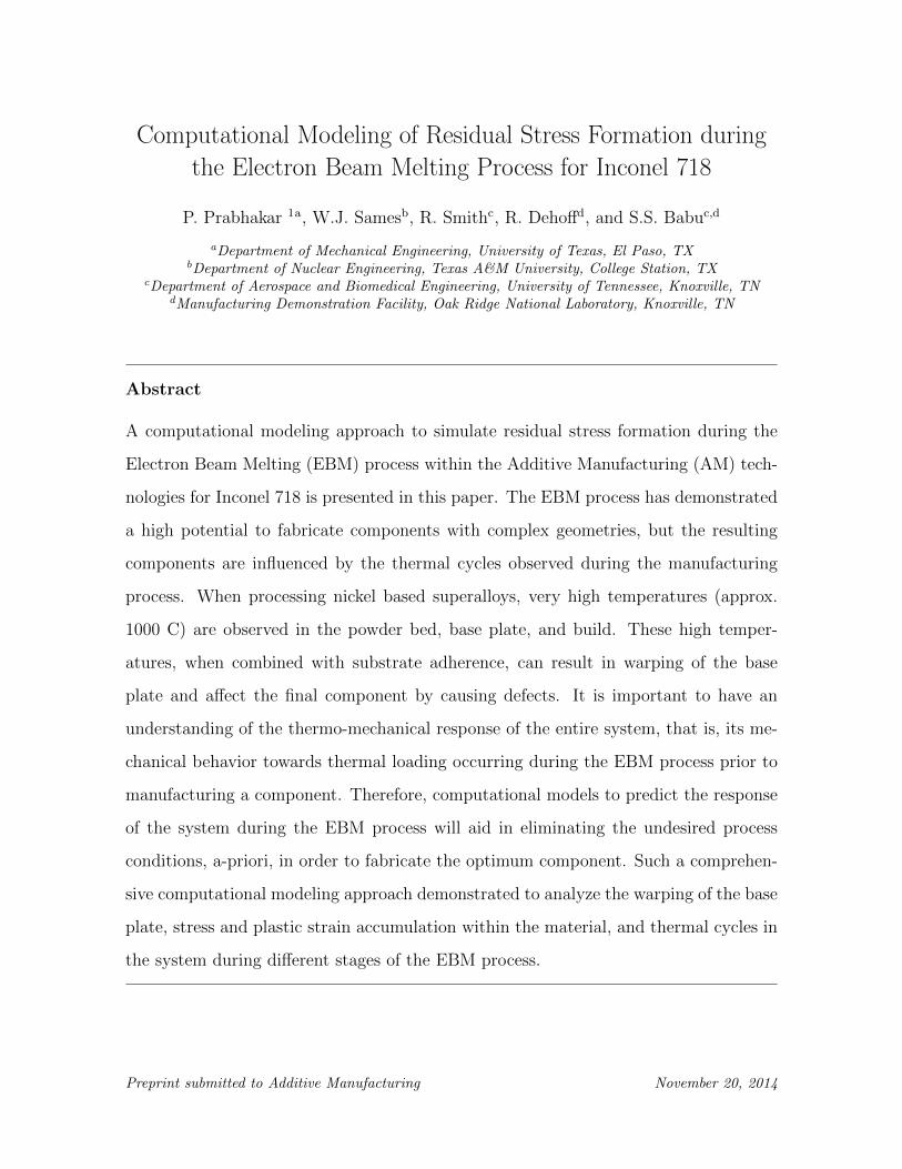
The computational model considered for this study is a build with tensile test
coupons as shown in Fig. 1. The build consists of a Inconel 718 powder bed (red
region), a stainless steel base plate (blue region) and six Inconel 718 coupons (green
region). The base plate is sintered into the powder bed, as shown in Fig. 1(a). The
coupon dimensions are 8 cm x 1.8 cm x 2 cm, and the dimension of the base plate are
15 cm x 15 cm x 1 cm. For clarity, Fig. 1(b) displays only the tensile test coupons and
the base plate.
A layer by layer model for the coupon build with 50 layers is constructed using com-
mercially available finite element analysis (FEA) software (ABAQUS 6.12) to simulate
the EBM process. A thermal analysis is conducted first to determine the temperature
distribution within the model, followed by a structural analysis to determine the stress,
3
(a) (b)
Figure 1: Tensile Test Coupon Build Model (a) with Powder Bed and (b) without Powder Bed
stain and deformation caused due to the heat imparted to the model during the EBM
process. Details of the material properties used, the thermal and the stress analyses
conducted are given in the following sections.
3. Material System
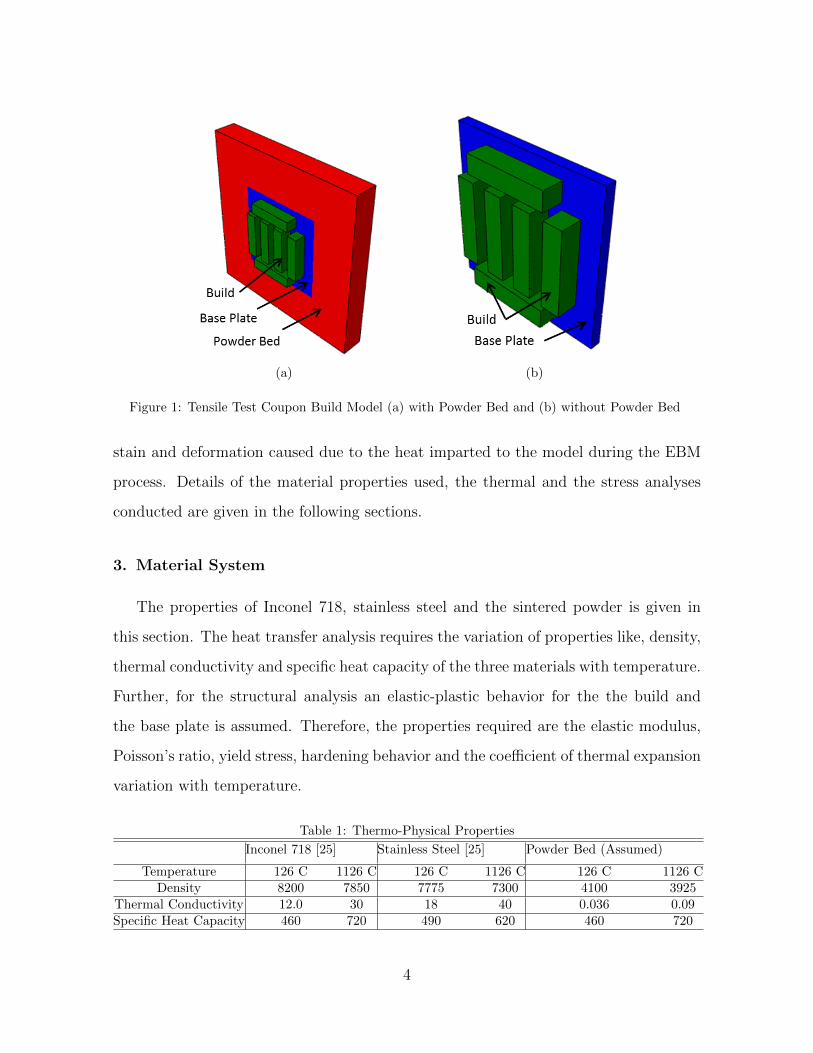
The properties of Inconel 718, stainless steel and the sintered powder is given in
this section. The heat transfer analysis requires the variation of properties like, density,
thermal conductivity and specific heat capacity of the three materials with temperature.
Further, for the structural analysis an elastic-plastic behavior for the the build and
the base plate is assumed. Therefore, the properties required are the elastic modulus,
Poisson’s ratio, yield stress, hardening behavior and the coefficient of thermal expansion
variation with temperature.
Table 1: Thermo-Physical Properties
Inconel 718 [25] Stainless Steel [25] Powder Bed (Assumed)
Temperature 126 C 1126 C 126 C 1126 C 126 C 1126 CDensity 8200 7850 7775 7300 4100 3925
Thermal Conductivity 12.0 30 18 40 0.036 0.09Specific Heat Capacity 460 720 490 620 460 720
4
The thermal-physical and mechanical properties used in the model are given in
Table 1 and Table 2, respectively.
Table 2: Mechanical Properties
Inconel 718 [26, 27] Stainless Steel [26, 27] Powder Bed (Assumed)
Temperature 93 C 760 C 20 C 500 C 25 C 500 CElastic Modulus 205 162 200 165 20 12Poisson’s Ratio 0.3 0.3 0.28 0.28 0.1 0.1
Yield Stress 1172 758 215 122 - -Hardening Coefficient 0.637 0.637 0.206 0.206 - -
Coeff. of Thermal Expansion 12.8e-6 16e-6 16e-6 18e-6 6e-6 8e-6
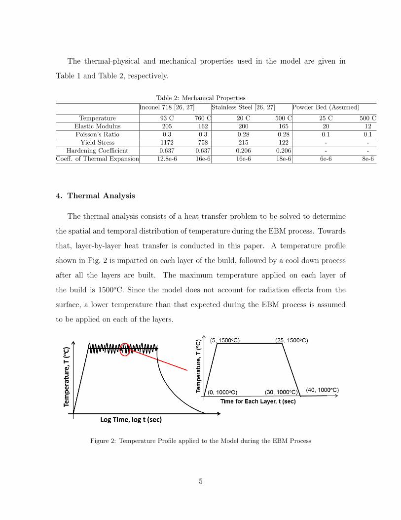
4. Thermal Analysis
The thermal analysis consists of a heat transfer problem to be solved to determine
the spatial and temporal distribution of temperature during the EBM process. Towards
that, layer-by-layer heat transfer is conducted in this paper. A temperature profile
shown in Fig. 2 is imparted on each layer of the build, followed by a cool down process
after all the layers are built. The maximum temperature applied on each layer of
the build is 1500oC. Since the model does not account for radiation effects from the
surface, a lower temperature than that expected during the EBM process is assumed
to be applied on each of the layers.
Figure 2: Temperature Profile applied to the Model during the EBM Process
5
From the first law of thermodynamics, the heat equation accounting for the heat
generated and conducted is given by,
ρcp∂T
∂t=
∂
∂x(K
∂T
∂x) (1)
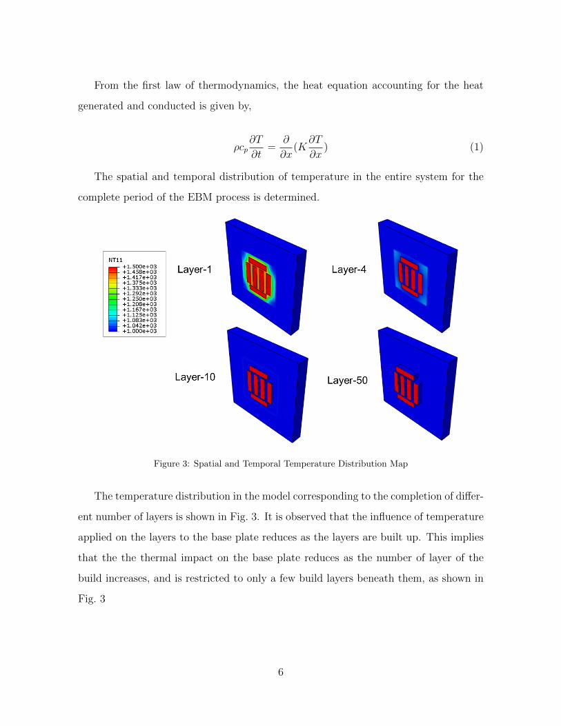
The spatial and temporal distribution of temperature in the entire system for the
complete period of the EBM process is determined.
Figure 3: Spatial and Temporal Temperature Distribution Map
The temperature distribution in the model corresponding to the completion of differ-
ent number of layers is shown in Fig. 3. It is observed that the influence of temperature
applied on the layers to the base plate reduces as the layers are built up. This implies
that the the thermal impact on the base plate reduces as the number of layer of the
build increases, and is restricted to only a few build layers beneath them, as shown in
Fig. 3
6

5. Stress Analysis
The temperature distribution in the model for the entire process obtained from the
thermal analysis is then applied to the model in order to conduct the stress analysis.
Again, a layer-by-layer analysis is conducted to investigate the influence of the heat
applied during the EBM process on the stress, strain and deformation in the model.
The equilibrium equation shown below is solved numerically within the FEM frame-
work to determine the displacement field in the model for the temperature field and
mechanical boundary conditions applied.
∂σ
∂x+ f = 0
u1 = 0 @ x1 = 0; u1 = 0 @ x1 = L
u2 = 0 @ x2 = 0; u2 = 0 @ x2 = W
u3 = 0 @ x3 = 0
(2)
where, ui, i = 1, 2, 3 are the displacements in the x, y and z-directions, L and W are
the dimensions of the powder bed in the x and y-directions, respectively. The bottom
of the powder bed (x3 = 0) is fixed (u3 = 0) in the z-direction. The fixed boundary
conditions applied are on the faces of the powder bed, and and not on the base plate or
the build. Therefore, the base plate and build are sitting on a bed of the Inconel 718
powder.
The maximum principal strain and stress on the top and bottom faces of the base
plate are plotted in Fig. 4. Stresses and plastic strain accumulation in the base plate
appear to be high after the end of the EBM process, which indicate that the coupons
obtained will be deformed. Therefore, the quality of the coupons are affected by the
warping of the base plate during the EBM process.
The deformation of the base plate along with the build is shown in Fig. 5 at differ-
ent times that correspond to different number of layers built on the base plate. It is
7

Figure 4: Map of Plastic Strain Accumulation and Residual Stresses in the Base Plate
Figure 5: Deformation of the Base Plate with Build at Different Times
observed that the top face of the base plate bulges upward during the build process.
The red regions around the build represent higher extent of the bulge compared to the
builds, which implies that there is a warping in the plate that causes the coupons to
be deformed. The bulge in the base plate reduces with increasing number of layers of
8

the build, hinting that the layers built later are less deformed that the initial layers of
the build. After cool down there is a permanent upward warp in the base plate, but
the top of the build is fairly flat. Therefore, the bottom layers in the build are warped
more that the upper layers. Similar behavior is observed during the EBM process with
stainless steel base plate.
6. Qualitative Comparison of Deformation
A qualitative comparison of the deformation of the base plate and the coupon build
is conducted in this section. The plate deflection observed in the computational model
is qualitatively similar to the one observed in the experiments. The side views of the
plate deformation in the out of plane direction is shown in Fig. 6.
Figure 6: Comparison of the Model Deformation with Experiments
The deformation in the plate and the build are shown in Fig. 7. An overall warping
of the base plate is observed (Fig. 7(a)). A closer view of the build, shown in Fig. 7(b),
indicates that the build layers in the vicinity of the base plate are warped, but they
tend to become more even away from the base plate.
It is hypothesized that the warping of the base plate occurs during the building of
the initial few layers, due to the intensity of the electron beam. The influence of the
beam on the base plate reduces as the build progresses away from the baseplate. It
is observed in the computational model (Fig. 5) that the edges surrounding the build
appear to warp causing the bottom layers to warp as well. Therefore, measures should
9
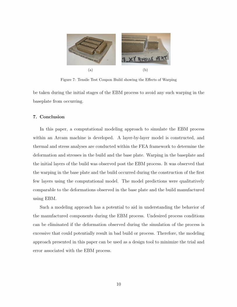
(a) (b)
Figure 7: Tensile Test Coupon Build showing the Effects of Warping
be taken during the initial stages of the EBM process to avoid any such warping in the
baseplate from occurring.
7. Conclusion
In this paper, a computational modeling approach to simulate the EBM process
within an Arcam machine is developed. A layer-by-layer model is constructed, and
thermal and stress analyses are conducted within the FEA framework to determine the
deformation and stresses in the build and the base plate. Warping in the baseplate and
the initial layers of the build was observed post the EBM process. It was observed that
the warping in the base plate and the build occurred during the construction of the first
few layers using the computational model. The model predictions were qualitatively
comparable to the deformations observed in the base plate and the build manufactured
using EBM.
Such a modeling approach has a potential to aid in understanding the behavior of
the manufactured components during the EBM process. Undesired process conditions
can be eliminated if the deformation observed during the simulation of the process is
excessive that could potentially result in bad build or process. Therefore, the modeling
approach presented in this paper can be used as a design tool to minimize the trial and
error associated with the EBM process.
10

8. Acknowledgements
Research sponsored by the U.S. Department of Energy, Office of Energy Efficiency
and Renewable Energy, Advanced Manufacturing Office, under contract DE-AC05-
00OR22725 with UT-Battelle, LLC. This research was also supported by fellowship
funding received from the U.S. Department of Energy, Office of Nuclear Energy, Nu-
clear Energy University Programs. The United States Government retains and the
publisher, by accepting the article for publication, acknowledges that the United States
Government retains a non-exclusive, paid-up, irrevocable, world-wide license to publish
or reproduce the published form of this manuscript, or allow others to do so, for United
States Government purposes. We would also like to thank ORNL HBCU/MEI summer
faculty opportunity for enabling the research presented in this paper. We would also
like to acknowledge The University of Texas at El Paso for enabling this opportunity
with ORNL.
References
[1] K.N. Amato, S.M. Gaytan, L.E. Murr, E. Martinez, P.W. Shindo, J. Hernandez, S. Collins, andF. Medina. Microstructures and mechanical behavior of inconel 718 fabricated by selective lasermelting. Acta Materialia, 60:22292239, 2012.
[2] Lawrence E. Murr, Edwin Martinez, Krista N. Amato, Sara M. Gaytan, Jennifer Hernan-dez, Diana A. Ramirez, Patrick W. Shindo, Frank Medina, and Ryan B. Wicker. Fabrica-tion of metal and alloy components by additive manufacturing: Examples of 3d materials sci-ence. Journal of Materials Research and Technology, 1(1):42 – 54, 2012. ISSN 2238-7854. doi:http://dx.doi.org/10.1016/S2238-7854(12)70009-1.
[3] Y. Tian, D. McAllister, H. Colijn, M. Mills, D. Farson, M. Nordin, and S. Babu. Rationalization ofmicrostructure heterogeneity in inconel 718 builds made by the direct laser additive manufacturingprocess. Metallurgical and Materials Transactions A, 45(10):4470–4483, 2014. ISSN 1073-5623.doi: 10.1007/s11661-014-2370-6.
[4] Z. Wang, K. Guan, M. Gao, X. Li, X. Chen, and X. Zeng. The microstructure and mechanicalproperties of deposited-in718 by selective laser melting. Journal of Alloys and Compounds, 513(0):518 – 523, 2012. ISSN 0925-8388. doi: http://dx.doi.org/10.1016/j.jallcom.2011.10.107.
[5] A. Strondl, M. Palm, J. Gnauk, and G. Frommeyer. Microstructure and mechanical properties ofnickel based superalloy in718 produced by rapid prototyping with electron beam melting (ebm).Materials Science and Technology, 27:876 – 883, 2011.
11
[6] W. J. Sames, K. A. Unocic, R. R. Dehoff, T. Lolla, and S. S. Babu. Thermal effects on mi-crostructural heterogeneity of inconel 718 materials fabricated by electron beam melting. Journalof Materials Research, 2014 (Accepted).
[7] K. A. Unocic, L. M. Kolbus, R. R. Dehoff, S. N. Dryepondt, and B. A. Pint. High-temperatureperformance of n07718 processed by additive manufacturing. NACE Corrosion 2014, San Antonio,TX.
[8] R. Dehoff, C. Duty, W. Peter, Y. Yamamoto, C. Wei, C. Blue, and C. Tallman. Case study:Additive manufacturing of aerospace brackets. Advanced Materials & Processes, 171:19 – 22,2013.
[9] D. D. Gu, W. Meiners, K. Wissenbach, and R. Poprawe. Laser additive manufacturing of metalliccomponents: materials, processes and mechanisms. International Materials Reviews, 57:133 –164, 2012.
[10] A. Chaudhary. Modeling of laser-additive manufacturing processes. ASM Handbook, 22B:240 –252, 2010.
[11] C. Zhang, L. Li, and A. Deceuster. Thermomechanical analysis of multi-bead pulsed laser powerdeposition of a nickel-based superalloy. Journal of Materials Processing Technology, 211:1478 –1487, 2011.
[12] H. Qi, M. Azer, and A. Ritter. Studies of standard heat treatment effects on microstructure andmechanical properties of laser net shape manufactured inconel 718. Metall. Mater. Trans. A., 40:2410 – 2422, 2009.
[13] X. Zhao, J. Chen, X. Lin, and W. Huang. Study on microstructure and mechanical properties oflaser rapid forming inconel 718. Materials Science and Engineering A, 478:119 – 124, 2008.
[14] F. Liu, X. Lin, C. Huang, M. Song, G. Yang, J. Chen, and W. Huang. The effect of laser scanningpath on microstructures and mechanical properties of laser solid formed nickel-base superalloyinconel 718. Journal of Alloys and Compounds, 509:4505 – 4509, 2011.
[15] Y. Zhang, Z. Li, P. Nie, and Y. Wu. Effect of heat treatment on niobium segregation of laser-cladded in718 alloy coating. Metall. Mater. Trans. A, 44A:706 – 718, 2013.
[16] I. Tabernero, A. Lamikiz, S. Martinez, E. Ukar, and J. Figuerasu. Evaluation of the mechanicalproperties of inconel 718 components built by laser cladding. International Journal of MachineTools & Manufacture, 51:456 – 470, 2011.
[17] S. S. Al-Bermani, M. L. Blackmore, W. Zhang, and I. Todd. The origin of microstructuraldiversity, texture, and mechanical properties in electron beam melted ti-6al-4v. Metallurgical andMaterials Transactions A, 41A(0):3422 – 3434, 2010.
[18] P. Mercelis and J.-P. Kruth. Residual stresses in selective laser sintering and selective lasermelting. Rapid Prototyping Journal, 12:254 – 265, 2006.
[19] T. Gnupel-Herold, J. Slotwinski, and S. Moylan. Neutron measurements of stresses in a testartifact produced by laser-based additive manufacturing. AIP Conference Proceedings, 1581:1205– 1212, 2014.
[20] P. Rangaswamy, T. M. Holden, R. B. Rogge, and M. L. Griffith. Residual stresses in componentsformed by the laser-engineered net shaping (lens & reg) process. Journal of Strain Analysis forEngineering Design, 38:519 – 527, 2003.
12

[21] L. M. Sochalski-Kolbus, E. A. Payzant, P. A. Cornwell, T. R. Watkins, S. S. Babu, R. R. De-hoff, and et al. Comparison of residual stresses in inconel 718 simple parts made by electronbeam melting and direct laser metal sintering. Metallurgical and Materials Transactions A, 2014.(submitted).
[22] A. Wu, M. M. LeBlanc, M. Kumar, G. F. Gallegos, D. W. Brown, and W. E. King. Effect oflaser scanning pattern and build direction in additive manufacturing on anisotropy, porosity andresidual stress. 2014 TMS Annual Meeting & Exhibition, San Diego, CA, 2014.
[23] J. Ding, P. Colegrove, J. Mehnen, S. Ganguly, P.M. Sequeira Almeida, F. Wang, and S. Williams.Thermo-mechanical analysis of wire and arc additive layer manufacturing process on large multi-layer parts. Computational Materials Science, 50(12):3315 – 3322, 2011. ISSN 0927-0256. doi:http://dx.doi.org/10.1016/j.commatsci.2011.06.023.
[24] M. Zaeh and G. Branner. Investigations on residual stresses and deformations in selective lasermelting. Production Engineering, 4(1):35–45, 2010. ISSN 0944-6524.
[25] COMSOL materials library [Inconel 718 (UNS N07718); Stainless Steel 304 (UNS S30400 solidpolished)].
[26] Inconel 718 technical data. High Temp Metals. URL http://www.hightempmetals.com.
[27] Elevated temperature physical properties of stainless steels. BS EN 10088-1. URLhttp://www.bssa.org.uk/topics.php?article=139.
13
Related Documents