Accepted Manuscript Computational fluid dynamic simulation of a sorption-enhanced palladium membrane reactor for enhancing hydrogen production from methane steam reforming Guozhao Ji, Ming Zhao, Geoff Wang PII: S0360-5442(18)30110-5 DOI: 10.1016/j.energy.2018.01.092 Reference: EGY 12204 To appear in: Energy Received Date: 18 February 2017 Revised Date: 22 November 2017 Accepted Date: 18 January 2018 Please cite this article as: Guozhao Ji, Ming Zhao, Geoff Wang, Computational fluid dynamic simulation of a sorption-enhanced palladium membrane reactor for enhancing hydrogen production from methane steam reforming, (2018), doi: 10.1016/j.energy.2018.01.092 Energy This is a PDF file of an unedited manuscript that has been accepted for publication. As a service to our customers we are providing this early version of the manuscript. The manuscript will undergo copyediting, typesetting, and review of the resulting proof before it is published in its final form. Please note that during the production process errors may be discovered which could affect the content, and all legal disclaimers that apply to the journal pertain.

Welcome message from author
This document is posted to help you gain knowledge. Please leave a comment to let me know what you think about it! Share it to your friends and learn new things together.
Transcript
Accepted Manuscript
Computational fluid dynamic simulation of a sorption-enhanced palladium membrane reactor for enhancing hydrogen production from methane steam reforming
Guozhao Ji, Ming Zhao, Geoff Wang
PII: S0360-5442(18)30110-5
DOI: 10.1016/j.energy.2018.01.092
Reference: EGY 12204
To appear in: Energy
Received Date: 18 February 2017
Revised Date: 22 November 2017
Accepted Date: 18 January 2018
Please cite this article as: Guozhao Ji, Ming Zhao, Geoff Wang, Computational fluid dynamic simulation of a sorption-enhanced palladium membrane reactor for enhancing hydrogen production from methane steam reforming, (2018), doi: 10.1016/j.energy.2018.01.092Energy
This is a PDF file of an unedited manuscript that has been accepted for publication. As a service to our customers we are providing this early version of the manuscript. The manuscript will undergo copyediting, typesetting, and review of the resulting proof before it is published in its final form. Please note that during the production process errors may be discovered which could affect the content, and all legal disclaimers that apply to the journal pertain.
ACCEPTED MANUSCRIPT
1 Computational fluid dynamic simulation of a sorption-
2 enhanced palladium membrane reactor for enhancing
3 hydrogen production from methane steam reforming
4 Guozhao Ji a, Ming Zhao a,* and Geoff Wang b
5 a School of Environment, Tsinghua University, Beijing 100084, China
6 b School of Chemical Engineering, the University of Queensland, Brisbane, Qld 4072,
7 Australia
8 * Corresponding Author. Tel: +86 10 62784701. Email: [email protected]
9 Abstract
10 To understand the reaction process of methane steam reforming in a sorption
11 enhanced membrane reactor (SEMR), a computational fluid dynamic (CFD) model
12 was developed to simulate the methane (CH4) steam reforming in a palladium-based
13 membrane reactor using a Ni-based catalyst and Na2ZrO3 CO2 sorbent. The CFD
14 model gained the insight of details in the reactor which could not be obtained by
15 experiment. With the detailed information, this model detected the difference of
16 reaction kinetics and fluid dynamic conditions in a SEMR and a traditional membrane
17 reactor (MR). The comparison suggests that sorption-enhanced membrane reactor not
18 only decreases CO2 fraction, but also improves hydrogen (H2) production by
19 increasing reaction rates, CH4 conversion and H2 yield. The poisoning effect of carbon
20 monoxide (CO) on the palladium membrane can also be minimized by reduced CO
ACCEPTED MANUSCRIPT
21 fraction as a result of in-situ CO2 capture.
22 Keywords: CFD simulation; sorption-enhanced membrane reactor; methane steam
23 reforming; hydrogen production; Ni catalyst; Na2ZrO3 sorbent
24
25 1. Introduction
26 Currently, fossil fuels are still the primary source for satisfying the growing energy
27 demand of our contemporary society. However, the growing level of CO2 from the
28 emission of fossil fuel combustion is increasing the concern of global warming. In the
29 case of low carbon emission technologies, H2 becomes an attractive alternative,
30 mainly due to its high calorific value and non-polluting emission [1]. H2 can be
31 produced via thermo-chemical processes from a variety of sources including biomass
32 [2, 3], natural gas [4, 5], coal [6, 7], water [8, 9], and some industrial waste chemicals
33 [10]. For most of these H2 production technologies, methane steam reforming (MSR),
34 referring to Eqn. R1 below, is a necessary step to convert CH4 and water to H2 [11].
35 CH4 + H2O ⇌ CO + 3 H2 ∆H298=-206.1 kJ mol-1 (R1)
36 However the H2 yield through reaction (R1) is accompanied with approximately
37 25 vol.% toxic gas CO. To avoid producing the toxic gas, water-gas shift (WGS)
38 reaction is usually implemented to further convert CO into H2 and a by-product CO2
39 (Eqn. R2).
40 CO + H2O ⇌ CO2 + H2 ∆H298=41.15 kJ mol-1 (R2)
ACCEPTED MANUSCRIPT
41 It should be noted that reaction (R1) is endothermic and reaction (R2) is
42 exothermic, which prevents them achieving high conversion simultaneously in a
43 single reactor where they are in the same temperature range. It is generally required to
44 control MSR at temperatures higher than 700 ºC. However WGS reacts efficiently
45 only below 450 ºC. For ordinary MSR hydrogen production, the hot gas mixture has
46 to be delivered from MSR reactor to WGS reactor, which resulted in a large energy
47 penalty due to the cooling down between reactors. In order to minimize this impact, a
48 membrane reactor was invented to allow these two reactions to proceed
49 simultaneously in a single reactor with better CH4 conversion and improved H2
50 production. The membrane is designed to be H2 selective, thus that H2 could be
51 partially removed continuously from the reactor by membrane permeation, meanwhile
52 sustaining other gas components in the reactor. In turn, the equilibriums of MSR and
53 WGS are shifted towards the H2 side owing to the H2 removal. Therefore, separating
54 H2 at high temperatures becomes attractive due to the reduction of energy penalties
55 associated with the cooling encountered in traditional MSR.
56 Among potential gas separation technologies, inorganic membranes such as
57 palladium-based membranes [12, 13] and silica-based membranes [14, 15] have
58 performed well at high temperatures. These membranes have been deployed in
59 membrane reactor configurations for H2 production via MSR [16, 17], WGS reactions
60 [18, 19], as well as dehydrogenation reactions [20]. The CH4 conversion enhancement
61 mainly depends on the H2 permeation. As is known that increasing the sweep flow
62 could improve H2 permeation. Anzelmo et al. enhanced the CH4 conversion from
ACCEPTED MANUSCRIPT
63 about 50% to 84% by varying the sweep flow 0 to 100 ml min-1 [21].
64 Based on open literatures in membrane reactor design, palladium-based
65 membranes showed superior popularity over silica-based membranes for its infinite
66 H2 selectivity and higher permeability [22, 23], though its capital cost is 2 orders of
67 magnitudes higher than the silica counterpart. However, CO, which is an inevitable
68 gas component in MSR, is an inhibitor for the palladium membrane because it affects
69 the H2 dissociation path [24]. The presence of CO is attributed to the faster reaction of
70 MSR than that of WGS. The net gain of CO accumulates in the reactor. Enhancing the
71 CO conversion is a feasible solution to reduce the CO concentration and resultantly
72 minimize its inhibition effect to palladium. Sufficiently removing H2 could possibly
73 achieve this goal in some situations. But once the membrane reactor needs to process
74 large quantity of gases, the high space velocity doesn't give sufficient retention time
75 for reactants to react and for H2 to permeate. Membrane reactors still suffer from low
76 conversions with high space velocities [25, 26].
77 Apart from H2 removal by membrane, capturing the other product gas (CO2), may
78 further shift the WGS reaction equilibrium towards H2+CO2 side and in turn enhance
79 the CO conversion. Furthermore, the CO depletion resulted from CO2 capture would
80 also enhance the MSR reaction towards the H2 side because CO is one of the products
81 of MSR. Regarding the in-situ CO2 capture, various materials such as CaO, Na2ZrO3,
82 and hydrotalcite have been used as sorbents and some of them was successfully
83 deployed to enhance MSR [27-31] and WGS [32]. If these sorbent materials were
84 integrated with membrane separation, a further enhancement of ‘shift effect’ could be
ACCEPTED MANUSCRIPT
85 expected for MSR. This type of configuration is called sorption enhanced membrane
86 reactor (SEMR). However, the number of publications with this idea is very limited
87 [33, 34]. Only Li et al. [33] and Madeira et al. [34] had used hydrotalcite as CO2
88 sorbent in palladium membrane for WGS. Other sorbent materials could also be
89 applied in membrane reactors for MSR. The limited number of studies using both
90 membrane and sorbents was owing to the complexity of synergistic effects among
91 MSR, WGS, membrane permeation and CO2 capture. Moreover, these synergistic
92 effects were difficult to be studied experimentally. Zhang et al.[35] and Chen et
93 al.[36] deployed one dimensional ‘plug flow’ model to calculate the sorption
94 enhanced membrane reactor performance. However, plug flow model was criticized
95 by Koukou et al.[37] due to the inadequacy in considering radial profile. CFD
96 simulation which gives the distributed three-dimensional information is need to get an
97 insight of reaction details in a reactor. There hasn't been a CFD model study to
98 interpret and analyze the MSR performance in a SEMR. This study for the first time
99 will deploy CFD simulation to fill this knowledge gap and fulfill the need of
100 investigating the coupled processes and assist the analysis of the shift effect.
101 This work is aimed to investigate the enhancement of MSR process by applying
102 membrane separation and in-situ CO2 sorption together in one reactor as described in
103 Fig. 1. The processes in this reactor include MSR, WGS, H2 permeation and CO2
104 sorption. H2 permeation and CO2 capture reduce the product concentration and shift
105 the reactions towards products side on basis of Le Chatelier’s principle. The dynamics
106 and the equilibria of these processes depend on the fluid dynamic conditions such as
ACCEPTED MANUSCRIPT
107 gas component concentration, pressure and temperature. In turn, these processes will
108 also affect the fluid dynamic conditions. All the processes and fluid dynamic
109 conditions are inter-correlated and spatially distributed in a reactor. It is extremely
110 difficult, if not impossible, to measure all the concerned parameters inside the reactor
111 experimentally. In order to better understand the reaction processes, detailed
112 information (e.g. gas concentration distribution) inside a reactor should be studied. To
113 address this problem, computational fluid dynamics (CFD) simulation can be used to
114 correlate fluid dynamics with space coordinate and time [38], thus provide detailed
115 gas flow characteristics and the distributed reaction kinetics in a membrane reactor
116 with CO2 sorption for MSR. The source term in CFD allowed the reactions and
117 permeation to be written in the CFD governing equations to couple the microscopic
118 model (reactions, permeation) with macroscopic model (fluid dynamics). As a result,
119 the CFD simulation can become a feasible tool to improve the design of given
120 membrane reactor and improve the operation of methane steam reforming in the
121 membrane reactor. Therefore, we will carry out a CFD simulation of SEMR. The
122 simulation with distributed information such as reaction rates and gas concentrations
123 would assist the analysis and improvement of the reactor performance, especially the
124 CH4 conversion and CO concentration.
125
126 2. Model description
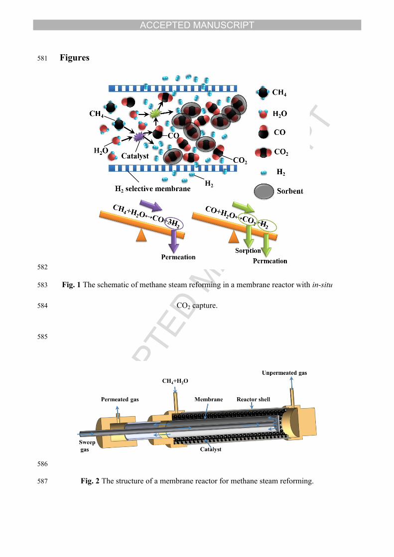
127 The design of the membrane reactor investigated in this work is depicted in Fig. 2.
ACCEPTED MANUSCRIPT
128 The reactant gases, CH4+H2O, were fed from the inlet of the reactor. As the gases
129 flowed in the catalyst packed bed, MSR and WGS proceeded. The generated H2 that
130 permeated across the membrane was collected with sweep N2 via the outlet. The
131 unpermeated gas exited the reactor from the right outlet. For the case with in-situ CO2
132 sorption, the catalyst would mix with CO2 sorbents and some generated CO2 may be
133 captured by the sorbents.
134 The MSR, WGS, H2 permeation and CO2 sorption only occur between the feed
135 inlet and the outlet of the unpermeated gas. For simplicity, the CFD model only
136 simulated the processes in the zone between the membrane and the reactor shell,
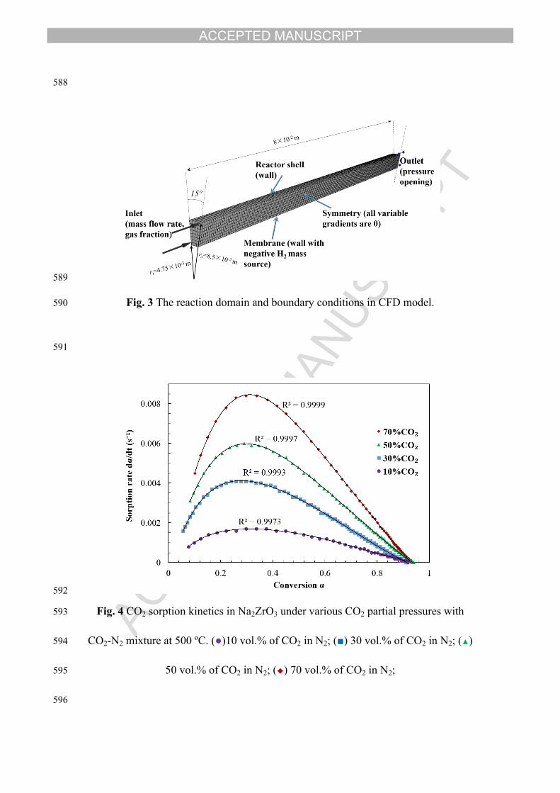
137 which is made from a hollow cylinder. In view of the axial symmetry of the reactor, a
138 15º portion of the reacting zone with symmetry planes on both side was simulated to
139 save the computational time (Fig. 3). The boundary condition of inlet was mass
140 flowrate with fixed composition of CH4 and H2O vapor. The outlet was a pressure
141 opening. The reactor shell was set as wall. The membrane was also set as wall, but
142 with negative H2 mass source to represent the H2 permeation. At the two symmetries,
143 there was no tangential gradient for any variables. The structured mesh was created
144 from inlet to outlet by sweep method to facilitate the computation speed.
145 The CFD model is mathematically expressed by the governing equations
146 consisting of continuity equations and momentum equations. The continuity equation
147 governs the mass balance, giving
148 (1) ct1 1
r zc r c u c u c u St r r r z
149 where is the source term caused by the processes which break the total mass ctS
ACCEPTED MANUSCRIPT
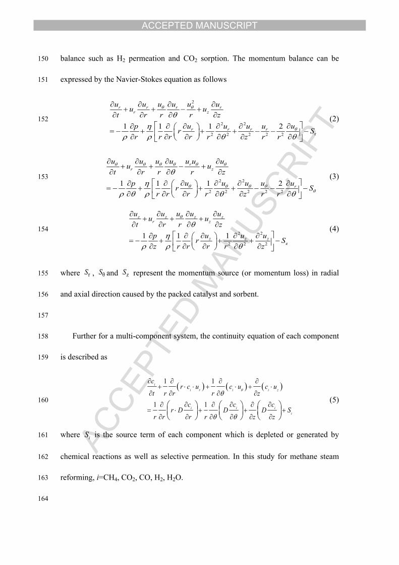
150 balance such as H2 permeation and CO2 sorption. The momentum balance can be
151 expressed by the Navier-Stokes equation as follows
152 (2)
2
2 2
r2 2 2 2 21 1 1 2
r r r rr z
r r r r
u uu u u uu ut r r r z
uu u u up r Sr r r r r z r r
153 (3)2 2
2 2 2 2 21 1 1 2
rr z
r
u u u u u u uu ut r r r z
u u u u up r Sr r r r z r r
154 (4)2 2
z2 2 21 1 1
z z z zr z
z z z
uu u u uu ut r r z
u u up r Sz r r r r z
155 where , and represent the momentum source (or momentum loss) in radial rS θS zS
156 and axial direction caused by the packed catalyst and sorbent.
157
158 Further for a multi-component system, the continuity equation of each component
159 is described as
160 (5) 1 1
1 1
ii r i i z
i i ii
cr c u c u c u
t r r r zc c c
r D D D Sr r r r z z
161 where is the source term of each component which is depleted or generated by iS
162 chemical reactions as well as selective permeation. In this study for methane steam
163 reforming, i=CH4, CO2, CO, H2, H2O.
164
ACCEPTED MANUSCRIPT
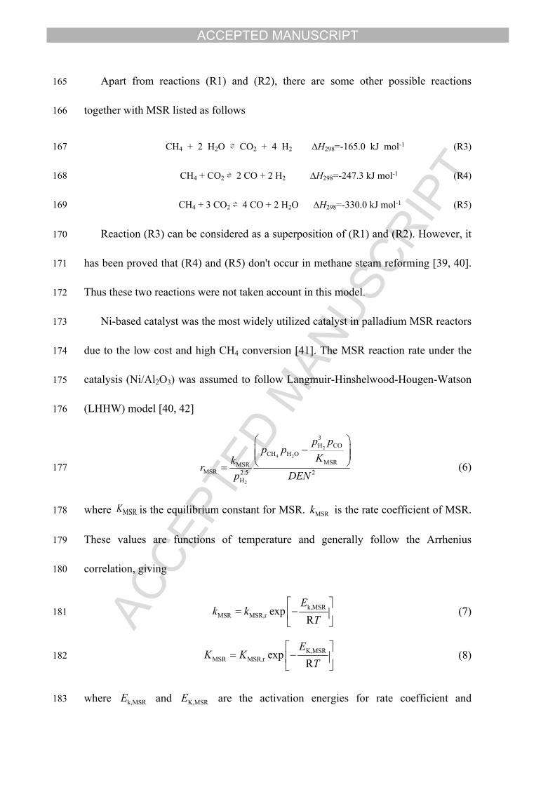
165 Apart from reactions (R1) and (R2), there are some other possible reactions
166 together with MSR listed as follows
167 CH4 + 2 H2O ⇌ CO2 + 4 H2 ∆H298=-165.0 kJ mol-1 (R3)
168 CH4 + CO2 ⇌ 2 CO + 2 H2 ∆H298=-247.3 kJ mol-1 (R4)
169 CH4 + 3 CO2 ⇌ 4 CO + 2 H2O ∆H298=-330.0 kJ mol-1 (R5)
170 Reaction (R3) can be considered as a superposition of (R1) and (R2). However, it
171 has been proved that (R4) and (R5) don't occur in methane steam reforming [39, 40].
172 Thus these two reactions were not taken account in this model.
173 Ni-based catalyst was the most widely utilized catalyst in palladium MSR reactors
174 due to the low cost and high CH4 conversion [41]. The MSR reaction rate under the
175 catalysis (Ni/Al2O3) was assumed to follow Langmuir-Hinshelwood-Hougen-Watson
176 (LHHW) model [40, 42]
177 (6)
2
4 2
2
3H CO
CH H OMSRMSR
MSR 2.5 2H
p pp p
Kkrp DEN
178 where is the equilibrium constant for MSR. is the rate coefficient of MSR. MSRK MSRk
179 These values are functions of temperature and generally follow the Arrhenius
180 correlation, giving
181 (7)k,MSRMSR MSR,r exp
RE
k kT
182 (8)K,MSRMSR MSR,r exp
RE
K KT
183 where and are the activation energies for rate coefficient and k,MSRE K,MSRE
ACCEPTED MANUSCRIPT
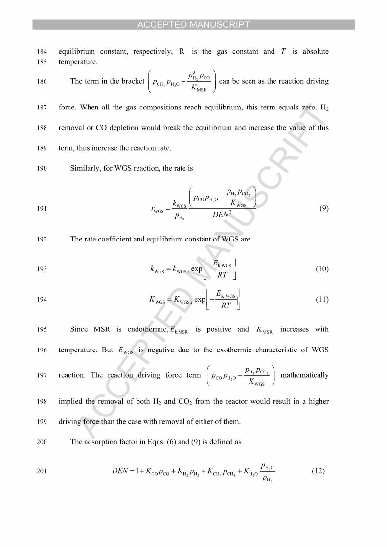
184 equilibrium constant, respectively, is the gas constant and is absolute R T185 temperature.
186 The term in the bracket can be seen as the reaction driving 2
4 2
3H CO
CH H OMSR
p pp p
K
187 force. When all the gas compositions reach equilibrium, this term equals zero. H2
188 removal or CO depletion would break the equilibrium and increase the value of this
189 term, thus increase the reaction rate.
190 Similarly, for WGS reaction, the rate is
191 (9)
2 2
2
2
H COCO H O
WGSWGSWGS 2
H
p pp p
Kkrp DEN
192 The rate coefficient and equilibrium constant of WGS are
193 (10)k,WGSWGS WGS,r exp
Ek k
RT
194 (11)K,WGSWGS WGS,r exp
EK K
RT
195 Since MSR is endothermic, is positive and increases with k,MSRE MSRK
196 temperature. But is negative due to the exothermic characteristic of WGS WGSE
197 reaction. The reaction driving force term mathematically 2 2
2
H COCO H O
WGS
p pp p
K
198 implied the removal of both H2 and CO2 from the reactor would result in a higher
199 driving force than the case with removal of either of them.
200 The adsorption factor in Eqns. (6) and (9) is defined as
201 (12) 2
2 2 4 4 2
2
H OCO CO H H CH CH H O
H
1p
DEN K p K p K p Kp
ACCEPTED MANUSCRIPT
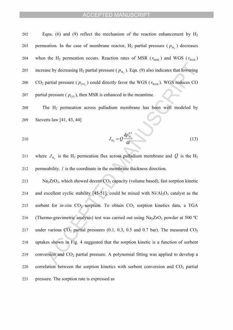
202 Eqns. (6) and (9) reflect the mechanism of the reaction enhancement by H2
203 permeation. In the case of membrane reactor, H2 partial pressure ( ) decreases 2Hp
204 when the H2 permeation occurs. Reaction rates of MSR ( ) and WGS ( ) MSRr WGSr
205 increase by decreasing H2 partial pressure ( ). Eqn. (9) also indicates that lowering 2Hp
206 CO2 partial pressure ( ) could directly favor the WGS ( ). WGS reduces CO 2COp WGSr
207 partial pressure ( ), then MSR is enhanced in the meantime. COp
208 The H2 permeation across palladium membrane has been well modeled by
209 Sieverts law [41, 43, 44]
210 (13)2
2
0.5
H
dd
HpJ Q
l
211 where is the H2 permeation flux across palladium membrane and is the H2 2HJ Q
212 permeability. is the coordinate in the membrane thickness direction. l
213 Na2ZrO3, which showed decent CO2 capacity (volume based), fast sorption kinetic
214 and excellent cyclic stability [45-51], could be mixed with Ni/Al2O3 catalyst as the
215 sorbent for in-situ CO2 sorption. To obtain CO2 sorption kinetics data, a TGA
216 (Thermo-gravimetric analysis) test was carried out using Na2ZrO3 powder at 500 ºC
217 under various CO2 partial pressures (0.1, 0.3, 0.5 and 0.7 bar). The measured CO2
218 uptakes shown in Fig. 4 suggested that the sorption kinetic is a function of sorbent
219 conversion and CO2 partial pressure. A polynomial fitting was applied to develop a
220 correlation between the sorption kinetics with sorbent conversion and CO2 partial
221 pressure. The sorption rate is expressed as
ACCEPTED MANUSCRIPT
222 (14)2CO mol max
dd
r Mt
223 where is the apparent molar density of the sorbent and is the maximum mol maxM
224 CO2 molar capacity. The fitted correlation from the experimental sorption test was
225 included in the CFD model to account for CO2 depletion in the reactor.
226 The sorbent conversion is a function to time based on Eqn. (15), giving
227 (15)ddt t t t
t
228 In addition to CO2 capture, Na2ZrO3 was also reported for some catalytic effect in
229 reforming and WGS reactions [52]. However, the catalytic effect from alkali catalyst
230 occurs only when the temperature is greater than 800 ºC [53], thus this model
231 assumed that the catalytic effect of Na2ZrO3 is minor compared to that of Ni and the
232 catalytic effect of Na2ZrO3 was not taken into account in the model.
233
234 3. Mesh and time-step independence study
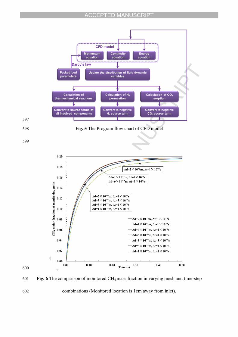
235 The flow diagram for the entire CFD model was illustrated in Fig. 5. The model was
236 solved by the commercial CFD code CFX (ANSYS Inc., US) in double precision
237 mode.
238
239 The partial differential equations (PDE) from (1) to (5) are continuous in space and
240 time. However, discretization must be adopted by mesh size and time step whereby
ACCEPTED MANUSCRIPT
241 the equations are replaced by the approximations using finite element method.
242 Numerical error is inevitable in finite element method, especially when the mesh size
243 and time step are large. Smaller mesh size and time step can deliver more precise
244 result but prolong the computational time. To ensure the precision of results from this
245 model, mesh and time-step independence study was performed by gradually reducing
246 mesh and time-step from a larger value until the results didn’t change with mesh and
247 time-step.
248 Under several mesh sizes and time-steps, the CH4 mass fraction at a point which
249 locates 1 cm from the inlet was recorded with simulation time. The reason to select
250 this monitoring point is that reactants are rich in this region and reactions are more
251 severe. It is more sensitive to detect the difference of result from different mesh
252 system. Meanwhile this point would give a quick response to the inlet flow to save the
253 simulation time. As shown in Fig. 6, the comparison of different time-step ∆t showed
254 that reducing ∆t from 0.001 s to 0.0005 s present no difference in the result,
255 suggesting that ∆t has little effect on the precision of results. As such, the ∆t=0.001 s
256 was used throughout this work. When the minimum mesh size was reduced from 2
257 mm to 0.5 mm, the monitored results were different, which implied that 2 mm mesh
258 size is too rough in this situation. Reducing the mesh size further to 0.3 and 0.1 mm
259 delivered same results to 0.5 mm mesh, which means 0.5 mm mesh size is already
260 sufficiently small to be used in approximating the PDE equations of the CFD model.
261 Finally the mesh system used in this study is 5632 hexahedra (number of nodes: 7965)
262 with max edge length ratio of 1.4634 and volume of 5.19955×10⁻⁷ m3.
ACCEPTED MANUSCRIPT
263
264 4. Model validation and results
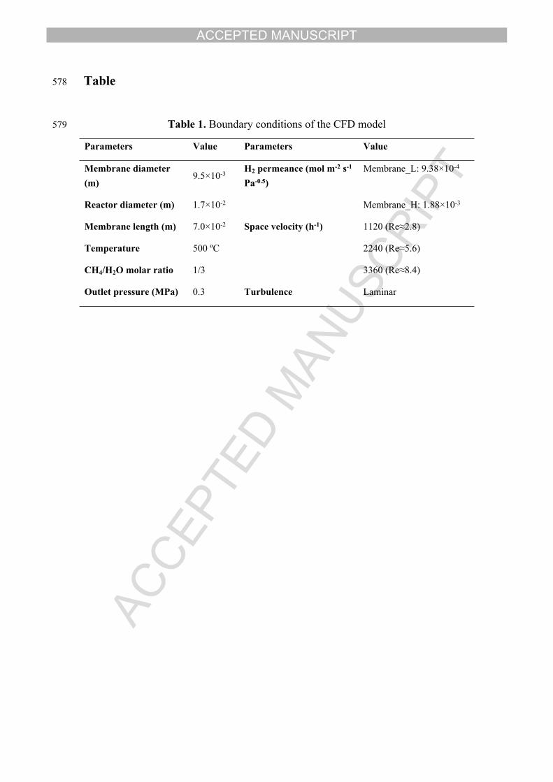
265 To validate this model, the model geometry and boundary conditions were set the
266 same as the experiment reported by Tong et al. [54] who carried out comprehensive
267 tests by using different palladium membrane reactors (Membrane_L and
268 Membrane_H) to produce H2 from MSR with varied space velocities (1120, 2240 and
269 3360 h-1). The reactor configuration was demonstrated in Fig. 2 and the detailed
270 boundary conditions were listed in Table 1. The experiment was conducted in a
271 membrane reactor without in-situ CO2 capture. So in the first step, the CFD model for
272 membrane reactor (MR) only included MSR, WGS and H2 permeation, but CO2
273 sorption was not considered in this model. The results from this model was denoted as
274 MR. This model was run for validation purpose. In the second step, it is assumed 20%
275 volume were occupied by Na2ZrO3 sorbent, thus the in-situ CO2 sorption was
276 included in the CFD model for sorption enhanced membrane reactor (SEMR). The
277 results from the model taking account of the CO2 sorption was denoted as SEMR. The
278 convergence criteria for all the simulations was set as 1×10⁻⁵ which means all the
279 errors of continuity equation, and each component (CH4, CO2, H2, CO, H2O)
280 continuity equation have to be less than 1×10⁻⁵.
281 CH4 conversion measured by experiment and computed from the CFD model
282 under identical operating conditions were compared for model validation (Fig. 7) for
283 two membrane reactors. It can be seen that the simulated CH4 conversion shown in
ACCEPTED MANUSCRIPT
284 Fig. 7 fits very well with the experimental CH4 conversion reported by Tong et
285 al.[54]. Based on this good agreement, this model is considered accurate permitting its
286 utilization for further simulations into understanding and analysis of the processes in
287 the reactor.
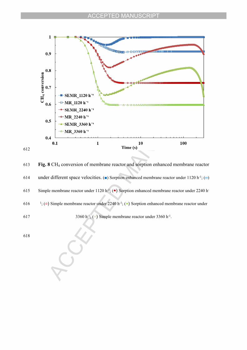
288 The further comparison was made between MR model and SEMR model (Fig. 8).
289 The addition of CO2 sorbents in SEMR model dramatically promoted the CH4
290 conversion with the greatest enhancement of 37% for 3360 h-1 space velocity. For the
291 case of 3360 h-1, the advantage of SEMR over MR prevailed from around the 1st sec
292 until 300th sec. Prior to the 1st sec, the CO2 sorption hadn’t commenced yet. This is
293 because the sorption rate is slow when the sorbent conversion α is low (Fig. 4).
294 Therefore, during this initial period, the SEMR showed little difference from MR.
295 Once the sorbents started to capture CO2 efficiently, CH4 conversion increased due to
296 the equilibrium shifting caused by CO2 sorption. As the sorbent conversion
297 approached to saturation (α→1) when the sorbents were used for longer time, the CO2
298 sorption kinetic decreased to almost zero as presented in Fig. 4. Thus the MSR and
299 WGS enhancement by sorption would vanish. Therefore, the CH4 conversion in
300 SEMR dropped to the level of that in MR.
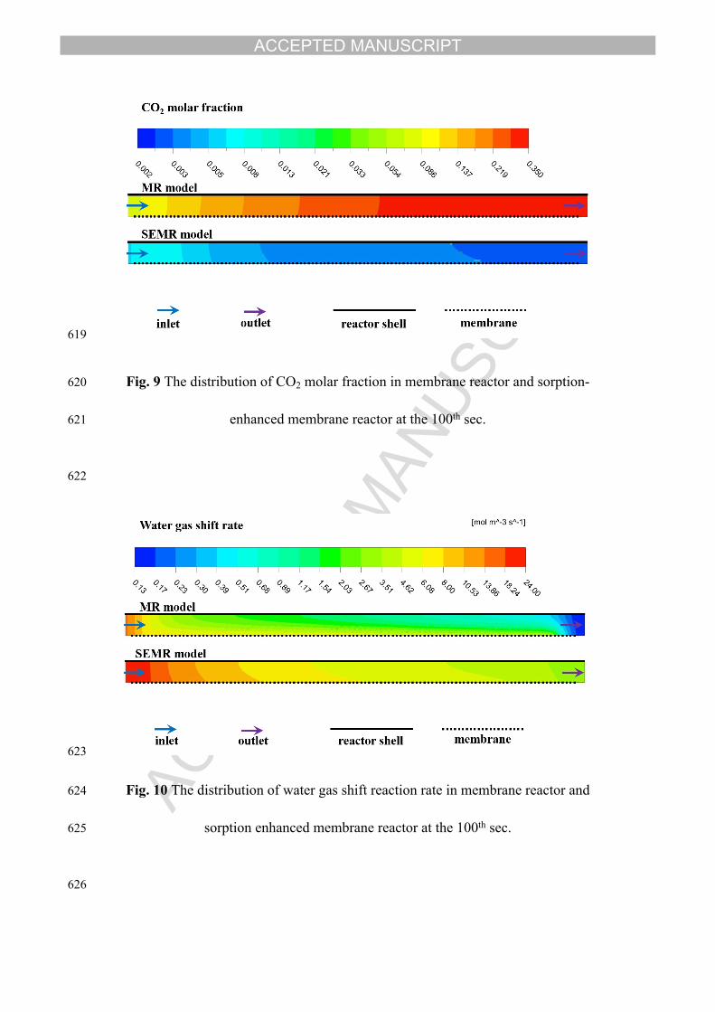
301 In order to reveal the reason of the different performance in MR and SEMR, the
302 map of CO2 molar fractions on the symmetry plane (refer to Fig. 3) at the 100th sec in
303 MR and SEMR were compared in Fig. 9. In the MR, CO2 fraction was increasing with
304 the flow (from inlet to outlet) due to the accumulation of generated CO2 from WGS
305 reaction. In the radial direction (from membrane to reactor shell), CO2 fraction
ACCEPTED MANUSCRIPT
306 slightly decreased. This is because the H2 permeation promoted WGS, thus WGS
307 produced more CO2 at the vicinity of the membrane. On the contrary, in the sorption
308 enhanced membrane reactor, CO2 fraction decreased with the flow, which indicated
309 that the CO2 sorption rate is close to the CO2 generation rate from WGS. The level of
310 CO2 fraction is 2 orders of magnitudes lower in the SEMR than in the simple MR.
311 Since WGS reaction could be enhanced directly by the in-situ CO2 sorption, the
312 map of WGS reaction rate ( ) in each reactor was then graphed in Fig. 10. In MR, WGSr
313 the WGS reaction rate decreased in the radial direction (from membrane surface to the
314 reactor shell), confirming the enhancement by H2 permeation as the effect was greater
315 near the membrane. The decrement of WGS reaction rate in the axial direction from
316 the inlet to the outlet is due to the CO2 fraction increment, which reduced the WGS
317 driving force based on Eqn. (9). Since the overall CO2 fraction in SEMR is much
318 lower than that MR, around 1 order of magnitude higher reaction rate was observed
319 for the SEMR owing to the CO2 sorption.
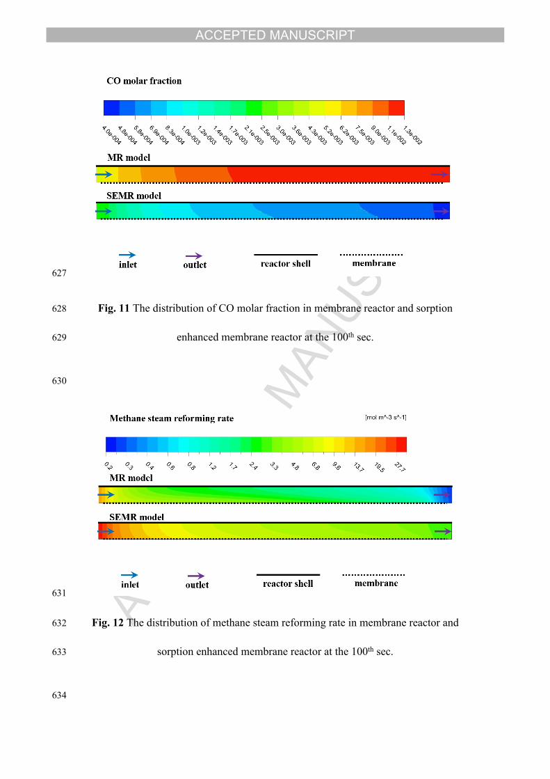
320 As mentioned above for palladium-based membrane, the presence of CO inhibits
321 H2 dissociation and permeation, so the CO concentration level in a palladium
322 membrane reactor is of special importance. Fig. 11 showed the CO molar fraction
323 distribution in the two reactors. Significant reduction of CO fraction was seen in
324 SEMR, which is below 0.2% throughout the entire membrane length. But in the
325 simple MR reactor, the CO fraction reached up to 1.3%. Consequently, the palladium
326 membrane suffers a higher risk of performance decay.
327 With higher WGS reaction rates, according to Eqn. (6) the rate of methane steam
ACCEPTED MANUSCRIPT
328 reforming would be further enhanced as a consequence of lower CO fraction. This
329 prediction was confirmed by the methane steam reforming rate ( ) in Fig. 12, MSRr
330 which showed that SEMR reformed methane at a faster rate than MR. If the methane
331 steam reforming rate at any location in SEMR is faster than that in MR, the overall
332 CH4 converted must be more for SEMR. This map of methane steam reforming rate
333 (Fig. 12) explained why SEMR improved CH4 conversion by 37% (Fig. 8).
334 The main target of the whole process is to produce H2, therefore, H2 production is
335 of the greatest interest in methane steam reforming. On basis of reactions (R1) and
336 (R2), H2 yield is directly related to the MSR and WGS rate. Figs. 12 and 10 had
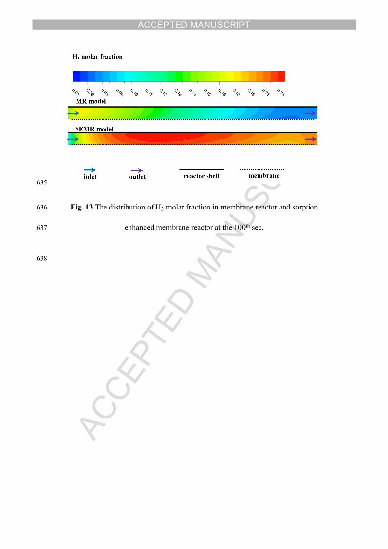
337 demonstrated the improvement of MSR and WGS for SEMR, thus higher H2 fraction
338 could be certainly expected from SEMR. Fig. 13 displayed the H2 fraction map of MR
339 and SEMR. The comparison demonstrated evident enhancement of H2 concentration
340 in SEMR. The generated H2 would eventually be collected in the permeate stream as
341 pure H2 and the outlet stream as H2 rich gas. The remarkable enrichment of H2 in the
342 reactor would provide a higher driving force for the membrane permeation. The
343 calculated H2 permeation of SEMR being 2.87×10⁻⁴ mol s-1 was 29% higher than that
344 of MR being 2.23×10⁻⁴ mol s-1. In addition to the pure H2 production in the permeate
345 stream, the unpermeated H2 was also collected in the meantime at the outlet stream.
346 The H2 flow at the outlet was 8.42×10⁻⁵ mol s-1 for SEMR and 5.67×10⁻⁵ mol s-1 for
347 MR. H2 dry base fraction at the outlet was 80.79 mol.% for SEMR and 34.47 mol.%
348 for MR. Beside the pure H2 in permeate stream, the SEMR configuration can also
349 produce high purity H2 in the outlet stream owing to the decline of CO, CO2 (Fig. S1)
ACCEPTED MANUSCRIPT
350 and more complete conversion of CH4.
351
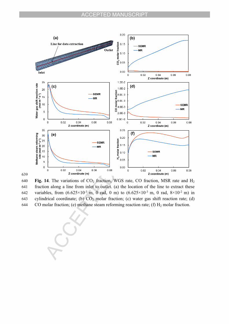
352 The variations of CO2 fraction, WGS rate, CO fraction, MSR rate and H2 fraction
353 are plotted as curves along a line from inlet to outlet in Fig. 14. The location of the
354 line to extract those values is shown in Fig. 14(a). The reductions of outlet CO2 and
355 CO were more than 95% by deploying SEMR. The reduced CO2 and CO
356 concentration in the SEMR almost doubled the WGS rate and MSR rate, which made
357 the reactor rich in H2. The SEMR showed superior performance over simple MR in
358 terms of CH4 conversion, CO reduction and H2 yield.
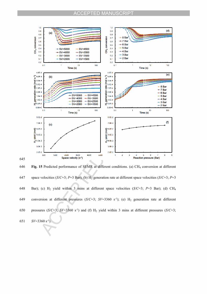
359 Sensitivity analysis of operating parameters in this SEMR CFD model is a
360 pathway to identify how the output changes with these operating conditions, and
361 provides an instructive direction for improving the reactor performance. A key
362 operating parameter to inspect in this study is the space velocity as it affects the CH4
363 reaction time and the quantity of CH4 that the reactor processes in unit time. Reactor
364 pressure is another interesting parameter worth investigating, because increasing
365 pressure can accelerate both forward reaction and reverse reaction of R1. Owning to
366 the higher stoichiometric number of product gases in R1, higher pressure favors the
367 reverse reaction. However, elevated pressure facilitates H2 membrane permeation as
368 well as CO2 capture, hence it also favors forward reaction of R1 by removing more H2
369 and CO2. Fig. 15 predicated the performance of CH4 conversion, H2 generation rate
370 and total H2 yield within the initial 3 mins with varied space velocity and pressure.
371 Increasing the space velocity led to declined CH4 conversion due to the shortened
ACCEPTED MANUSCRIPT
372 reaction time. But H2 generation rate and H2 total yield increased with space velocity
373 as the reactor processed more CH4 per time. Higher pressure resulted in higher CH4
374 conversion which indicated that the total effect of enhanced pressure is positive for
375 the forward reaction. The effect of pressure on the H2 generation rate seems more
376 complicated. In the initial period of around 1 s, the H2 generation rate is favored at
377 lower pressure, in agreement with the intrinsic nature of R1. But after 1 second, the
378 shift effect from the removal of H2 and CO2 started to dominate and higher pressure
379 provided more severe shift effect, as a result H2 was produced at a faster rate at higher
380 pressures. The overall H2 yield within 3 mins was enhanced gradually by elevated
381 pressure.
382 However, the advantage of SEMR only presented in limited period. With longer
383 time operation, the sorbents will reach to the saturation and thus the SEMR will
384 eventually become a simple MR. More capital cost is required to construct a SEMR
385 than a MR due to the addition of sorbents. But the sorbents only occupy the space and
386 become functionless when they are saturated. To reuse the sorbents, regeneration is
387 needed, as such the reactor has to be operated in batch system. The idea of sorption
388 enhancement for membrane reactor could be further improved by using moving bed
389 or circulating fluidized bed which could be operated in continuous system. Therefore,
390 the greater performance of SEMR over MR is sustained all the time. Another issue
391 associated with SEMR is the sorbent regeneration is general operated at high
392 temperature (>850 ºC) which makes the process energy intensive. Furthermore, the
393 possible interaction between catalyst and sorbent may affect the performance of
ACCEPTED MANUSCRIPT
394 catalytic reaction and CO2 capture. This issue is worth investigating in future studies.
395
396 5. Conclusions
397 A computational fluid dynamic (CFD) model, which allows the access of dynamic
398 and distributed information of reactants and products in a sorption-enhanced
399 membrane reactor, was developed in this study. The model was validated by
400 comparing the simulated results with experimental results obtained from a membrane
401 reactor without CO2 sorbents. Further employment of this model was implemented to
402 explain the difference of reaction process between a SEMR and the traditional MR.
403 The results show that the SEMR not only reduced the CO2 fraction, but also increased
404 the rates of MSR and WGS as well as the yield of H2. The CO fraction level
405 decreased by 1 order of magnitude in the sorption-enhanced membrane reactor than
406 the traditional membrane reactor, which minimized the possibility of H2 permeation
407 decay. With the detailed information inside a reactor which is blind to experimental
408 measurements, this model could be used as a general tool to analyze the reaction
409 process and interpret reactor performance.
410
411 Nomenclature
c Gas concentration, mol m-3
ic Gas concentration of component i, mol m-3
ACCEPTED MANUSCRIPT
D Diffusion coefficient, m2 s-1
DEN Adsorption factor
k,MSRE Activation energy of rate coefficient for MSR, J mol-1
K,MSRE Activation energy of equilibrium constant for MSR, J mol-1
k,WGSE Activation energy of rate coefficient for WGS, J mol-1
K,WGSE Activation energy of equilibrium constant for WGS, J mol-1
2HJ H2 permeation flux across membrane, mol m-2 s-1
MSRk Rate coefficient of MSR, mol Pa0.5 m-3 s-1
MSR,rk Rate coefficient of MSR at reference temperature, mol Pa0.5 m-3 s-1
WGSk Rate coefficient of WGS, mol Pa-1 m-3 s-1
WGS,rk Rate coefficient of WGS at reference temperature, mol Pa-1 m-3 s-1
4CHK Sorption coefficient for CH4, Pa-1
COK Sorption coefficient for CO, Pa-1
2HK Sorption coefficient for H2, Pa-1
2H OK Sorption coefficient for H2O,
MSRK Equilibrium constant for MSR, Pa2
MSR,rK Equilibrium constant for MSR at reference temperature, Pa2
WGSK Equilibrium constant for WGS
WGS,rK Equilibrium constant for WGS at reference temperature
l Space coordinate in membrane thickness direction, m
maxM Maximum CO2 molar capacity
4CHp CH4 partial pressure, Pa
COp CO partial pressure, Pa
2COp CO2 partial pressure, Pa
ACCEPTED MANUSCRIPT
2Hp H2 partial pressure, Pa
2H Op H2O partial pressure, Pa
Q H2 permeability through palladium membrane, mol m-1 s-1 Pa-0.5
r Radial coordinate, m
2COr CO2 sorption rate, mol m-3 s-1
MSRr MSR reaction rate, mol m-3 s-1
WGSr WGS reaction rate, mol m-3 s-1
R Gas constant, 8.314 J mol-1 K-1
ctS Source term for continuity equation
iS Source term for component balance equation
rS Source term in radial direction for Navier-Stokes equation
zS Source term in axial direction for Navier-Stokes equation
t Time, s
T Temperature, K
ru Radial velocity, m s-1
u Tangential velocity, m s-1
zu Axial velocity, m s-1
z Axial coordinate, m
Sorbent conversion
Tangential coordinate
Density, kg m-3
mol Molar density of sorbent in the reactor, mol m-3
412
413 Abbreviations
ACCEPTED MANUSCRIPT
CFD Computational fluid dynamics
MR Membrane reactor
MSR Methane steam reforming
PDE Partial differential equation
SEMR Sorption-enhanced membrane reactor
WGS Water gas shift
414
415 Acknowledgement
416 M. Zhao thank for the support by the National Recruitment Program of Global Youth
417 Experts (The National Youth 1000 – Talent Program) of China (grant number:
418 20151710227) and the Tsinghua University Initiative Scientific Research Program
419 (grant number: 20161080094). G. Ji is grateful for the support by China Postdoctoral
420 Science Foundation (grant number: 2017M610910).
421
422 References
423 [1] R.C. Saxena, D. Seal, S. Kumar, H.B. Goyal. Thermo-chemical routes for 424 hydrogen rich gas from biomass: A review. Renew Sust Energ Rev 2008;12:1909-425 1927.426 [2] P. Ji, W. Feng, B. Chen. Production of ultrapure hydrogen from biomass 427 gasification with air. Chem Eng Sci 2009;64:582-592.428 [3] R. Khonde, A. Chaurasia. Rice husk gasification in a two-stage fixed-bed gasifier: 429 Production of hydrogen rich syngas and kinetics. Int J Hydrogen Energy 430 2016;41:8793-8802.431 [4] S.H.D. Lee, D.V. Applegate, S. Ahmed, S.G. Calderone, T.L. Harvey. Hydrogen 432 from natural gas: part I—autothermal reforming in an integrated fuel processor. Int J 433 Hydrogen Energy 2005;30:829-842.
ACCEPTED MANUSCRIPT
434 [5] J.R.H. Ross. Natural gas reforming and CO2 mitigation. Catal Today 435 2005;100:151-158.436 [6] H. Jin, Y. Lu, B. Liao, L. Guo, X. Zhang. Hydrogen production by coal 437 gasification in supercritical water with a fluidized bed reactor. Int J Hydrogen Energy 438 2010;35:7151-7160.439 [7] G.J. Stiegel, M. Ramezan. Hydrogen from coal gasification: An economical 440 pathway to a sustainable energy future. Int J Coal Geol 2006;65:173-190.441 [8] T.C. Woodbridge, D.D. Woodbridge. Ocean hydrogen for launch operations. Int J 442 Hydrogen Energy 1996;21:81-86.443 [9] J. Martinez-Frias, A.-Q. Pham, S. M. Aceves. A natural gas-assisted steam 444 electrolyzer for high-efficiency production of hydrogen. Int J Hydrogen Energy 445 2003;28:483-490.446 [10] B. McLellan, E. Shoko, A.L. Dicks, J.C. Diniz da Costa. Hydrogen production 447 and utilisation opportunities for Australia. Int J Hydrogen Energy 2005;30:669-679.448 [11] J. Adanez, A. Abad, F. Garcia-Labiano, P. Gayan, L.F. de Diego. Progress in 449 chemical-looping combustion and reforming technologies. Prog Energy Combust Sci 450 2012;38:215-282.451 [12] E. Fernandez, K. Coenen, A. Helmi, J. Melendez, J. Zuñiga, D.A. Pacheco 452 Tanaka, M. van Sint Annaland, F. Gallucci. Preparation and characterization of thin-453 film Pd–Ag supported membranes for high-temperature applications. Int J Hydrogen 454 Energy 2015;40:13463-13478.455 [13] S. Yun, S. Ted Oyama. Correlations in palladium membranes for hydrogen 456 separation: A review. J Membrane Sci 2011;375:28-45.457 [14] B. Ballinger, J. Motuzas, S. Smart, J.C. Diniz da Costa. Palladium cobalt binary 458 doping of molecular sieving silica membranes. Journal of Membrane Science 459 2014;451:185-191.460 [15] G. Ji, S. Smart, S.K. Bhatia, J.C. Diniz da Costa. Improved pore connectivity by 461 the reduction of cobalt oxide silica membranes. Sep Purif Technol 2015;154:338-344.462 [16] M. Patrascu, M. Sheintuch. On-site pure hydrogen production by methane steam 463 reforming in high flux membrane reactor: Experimental validation, model predictions 464 and membrane inhibition. Chem Eng J 2015;262:862-874.465 [17] J. Tong, Y. Matsumura. Effect of catalytic activity on methane steam reforming 466 in hydrogen-permeable membrane reactor. Appl Catal A-Gen 2005;286:226-231.467 [18] W.-H. Chen, T.-C. Hsieh, T.L. Jiang. An experimental study on carbon 468 monoxide conversion and hydrogen generation from water gas shift reaction. Energy 469 Convers Manage 2008;49:2801-2808.470 [19] S. Battersby, S. Smart, B. Ladewig, S. Liu, M.C. Duke, V. Rudolph, J.C.D.d. 471 Costa. Hydrothermal stability of cobalt silica membranes in a water gas shift 472 membrane reactor. Sep Purif Technol 2009;66:299-305.473 [20] S. Battersby, P.W. Teixeira, J. Beltramini, M.C. Duke, V. Rudolph, J.C. Diniz da 474 Costa. An analysis of the Peclet and Damkohler numbers for dehydrogenation 475 reactions using molecular sieve silica (MSS) membrane reactors. Catal Today 476 2006;116:12-17.477 [21] B. Anzelmo, J. Wilcox, S. Liguori. Natural gas steam reforming reaction at low
ACCEPTED MANUSCRIPT
478 temperature and pressure conditions for hydrogen production via Pd/PSS membrane 479 reactor. J Membrane Sci 2017;522:343-350.480 [22] J. Boon, J.A.Z. Pieterse, F.P.F. van Berkel, Y.C. van Delft, M. van Sint 481 Annaland. Hydrogen permeation through palladium membranes and inhibition by 482 carbon monoxide, carbon dioxide, and steam. J Membrane Sci 2015;496:344-358.483 [23] W.-H. Chen, P.-C. Hsu. Hydrogen permeation measurements of Pd and Pd–Cu 484 membranes using dynamic pressure difference method. Int J Hydrogen Energy 485 2011;36:9355-9366.486 [24] M. Coroneo, G. Montante, J. Catalano, A. Paglianti. Modelling the effect of 487 operating conditions on hydrodynamics and mass transfer in a Pd–Ag membrane 488 module for H2 purification. J Membrane Sci 2009;343:34-41.489 [25] J. Tong, Y. Matsumura, H. Suda, K. Haraya. Experimental study of steam 490 reforming of methane in a thin (6 μm) pd-based membrane reactor. Ind Eng Chem 491 Res 2005;44:1454-1465.492 [26] S. Battersby, M.C. Duke, S. Liu, V. Rudolph, J.C.D.d. Costa. Metal doped silica 493 membrane reactor: Operational effects of reaction and permeation for the water gas 494 shift reaction. J Membrane Sci 2008;316:46-52.495 [27] M. Shokrollahi Yancheshmeh, H.R. Radfarnia, M.C. Iliuta. High temperature 496 CO2 sorbents and their application for hydrogen production by sorption enhanced 497 steam reforming process. Chem Eng J 2016;283:420-444.498 [28] M. Zhao, X. Yang, T.L. Church, A.T. Harris. Interaction between a bimetallic 499 Ni–Co catalyst and micrometer-sized CaO for enhanced H2 production during 500 cellulose decomposition. Int J Hydrogen Energy 2011;36:421-431.501 [29] L. Barelli, G. Bidini, F. Gallorini, S. Servili. Hydrogen production through 502 sorption-enhanced steam methane reforming and membrane technology: A review. 503 Energy 2008;33:554-570.504 [30] E. Ochoa-Fernández, C. Lacalle-Vilà, T. Zhao, M. Rønning, D. Chen, 505 Experimental demonstration of H2 production by CO2 sorption enhanced steam 506 methane reforming using ceramic acceptors, in: M.S. Fábio Bellot Noronha, S.-A. 507 Eduardo Falabella (Eds.) Studies in Surface Science and Catalysis, Elsevier, 2007, pp. 508 159-164.509 [31] E. Ochoa-Fernandez, G. Haugen, T. Zhao, M. Ronning, I. Aartun, B. Borresen, 510 E. Rytter, M. Ronnekleiv, D. Chen. Process design simulation of H2 production by 511 sorption enhanced steam methane reforming: evaluation of potential CO2 acceptors. 512 Green Chemistry 2007;9:654-662.513 [32] E.R. van Selow, P.D. Cobden, P.A. Verbraeken, J.R. Hufton, R.W. van den 514 Brink. Carbon capture by sorption-enhanced water−gas shift reaction process using 515 hydrotalcite-based material. Ind Eng Chem Res 2009;48:4184-4193.516 [33] F.R. García-García, M. León, S. Ordóñez, K. Li. Studies on water–gas-shift 517 enhanced by adsorption and membrane permeation. Catal Today 2014;236, Part A:57-518 63.519 [34] M.A. Soria, S. Tosti, A. Mendes, L.M. Madeira. Enhancing the low temperature 520 water–gas shift reaction through a hybrid sorption-enhanced membrane reactor for 521 high-purity hydrogen production. Fuel 2015;159:854-863.
ACCEPTED MANUSCRIPT
522 [35] Y. Chen, A. Mahechabotero, C.J. Lim, J.R. Grace, J. Zhang, Y. Zhao, C. Zheng. 523 Hydrogen production in a sorption-enhanced fluidized-bed membrane reactor: 524 operating parameter investigation. Ind Eng Chem Res 2014;53:6230-6242.525 [36] Z. Chen, F. Po, J.R. Grace, C. Jim Lim, S. Elnashaie, A. Mahecha-Botero, M. 526 Rakib, Y. Shirasaki, I. Yasuda. Sorbent-enhanced/membrane-assisted steam-methane 527 reforming. Chem Eng Sci 2008;63:170-182.528 [37] M.K. Koukou, N. Papayannakos, N.C. Markatos. On the importance of non-ideal 529 flow effects in the operation of industrial-scale adiabatic membrane reactors. Chem 530 Eng J 2001;83:95-105.531 [38] G. Ji, G. Wang, K. Hooman, S. Bhatia, J. Diniz da Costa. Computational fluid 532 dynamics applied to high temperature hydrogen separation membranes. Front Chem 533 Sci Eng 2012;6:3-12.534 [39] J. Xu, G.F. Froment. Methane steam reforming, methanation and water-gas shift: 535 I. Intrinsic kinetics. AlChE J 1989;35:88-96.536 [40] K. Hou, R. Hughes. The kinetics of methane steam reforming over a Ni/α-Al2O 537 catalyst. Chem Eng J 2001;82:311-328.538 [41] A. Iulianelli, S. Liguori, J. Wilcox, A. Basile. Advances on methane steam 539 reforming to produce hydrogen through membrane reactors technology: A review. 540 Catal Rev 2016;58:1-35.541 [42] J. Xu, G.F. Froment. Methane steam reforming: II. Diffusional limitations and 542 reactor simulation. AlChE J 1989;35:97-103.543 [43] G.L. Holleck. Diffusion and solubility of hydrogen in palladium and palladium--544 silver alloys. J Phys Chem 2002;74.545 [44] T.L. Ward, T. Dao. Model of hydrogen permeation behavior in palladium 546 membranes. J Membrane Sci 1999;153:211-231.547 [45] H.R. Radfarnia, M.C. Iliuta. Application of surfactant-template technique for 548 preparation of sodium zirconate as high temperature CO2 sorbent. Sep Purif Technol 549 2012;93:98-106.550 [46] T. Zhao, E. Ochoa-Fernández, M. Rønning, D. Chen. Preparation and high-551 temperature CO2 capture properties of nanocrystalline Na2ZrO3. Chem Mater 552 2007;19:3294-3301.553 [47] I. Alcérreca-Corte, E. Fregoso-Israel, H. Pfeiffer. CO2 absorption on Na2ZrO3: A 554 kinetic analysis of the chemisorption and diffusion processes. J Phys Chem C 555 2008;112:6520-6525.556 [48] L. Martínez-dlCruz, H. Pfeiffer. Cyclic CO2 chemisorption–desorption behavior 557 of Na2ZrO3: Structural, microstructural and kinetic variations produced as a function 558 of temperature. J Solid State Chem 2013;204:298-304.559 [49] T. Zhao, M. Rønning, D. Chen. Preparation of nanocrystalline Na2ZrO3 for high-560 temperature CO2 acceptors: chemistry and mechanism. J Energy Chem 2013;22:387-561 393.562 [50] L. Martínez-dlCruz, H. Pfeiffer. Microstructural thermal evolution of the Na2CO3 563 phase produced during a Na2ZrO3–CO2 chemisorption process. J Phys Chem C 564 2012;116:9675-9680.565 [51] G.G. Santillán-Reyes, H. Pfeiffer. Analysis of the CO2 capture in sodium
ACCEPTED MANUSCRIPT
566 zirconate (Na2ZrO3). Effect of the water vapor addition. Int J Green Gas Con 567 2011;5:1624-1629.568 [52] M.Z. Memon, X. Zhao, V.S. Sikarwar, A.K. Vuppaladadiyam, S.J. Milne, A.P. 569 Brown, J. Li, M. Zhao. Alkali metal CO2 sorbents and the resulting metal carbonates: 570 potential for process intensification of sorption-enhanced steam reforming. Environ 571 Sci Technol 2017;51:12-27.572 [53] D. Sutton, B. Kelleher, J.R.H. Ross. Review of literature on catalysts for biomass 573 gasification. Fuel Process Technol 2001;73:155-173.574 [54] J. Tong, Y. Matsumura. Pure hydrogen production by methane steam reforming 575 with hydrogen-permeable membrane reactor. Catal Today 2006;111:147-152.576
ACCEPTED MANUSCRIPT
578 Table
579 Table 1. Boundary conditions of the CFD model
Parameters Value Parameters Value
Membrane diameter (m)
9.5×10⁻³ Membrane_L: 9.38×10⁻⁴
Reactor diameter (m) 1.7×10⁻²
H2 permeance (mol m-2 s-1 Pa-0.5)
Membrane_H: 1.88×10⁻³
Membrane length (m) 7.0×10⁻² 1120 (Re≈2.8)
Temperature 500 ºC 2240 (Re≈5.6)
CH4/H2O molar ratio 1/3
Space velocity (h-1)
3360 (Re≈8.4)
Outlet pressure (MPa) 0.3 Turbulence Laminar
ACCEPTED MANUSCRIPT
581 Figures
582
583 Fig. 1 The schematic of methane steam reforming in a membrane reactor with in-situ
584 CO2 capture.
585
586
587 Fig. 2 The structure of a membrane reactor for methane steam reforming.
ACCEPTED MANUSCRIPT
588
589
590 Fig. 3 The reaction domain and boundary conditions in CFD model.
591
592
593 Fig. 4 CO2 sorption kinetics in Na2ZrO3 under various CO2 partial pressures with
594 CO2-N2 mixture at 500 ºC. (●)10 vol.% of CO2 in N2; (■) 30 vol.% of CO2 in N2; (▲)
595 50 vol.% of CO2 in N2; (◆) 70 vol.% of CO2 in N2;
596
ACCEPTED MANUSCRIPT
597
598 Fig. 5 The Program flow chart of CFD model
599
600
601 Fig. 6 The comparison of monitored CH4 mass fraction in varying mesh and time-step
602 combinations (Monitored location is 1cm away from inlet).
ACCEPTED MANUSCRIPT
603
604
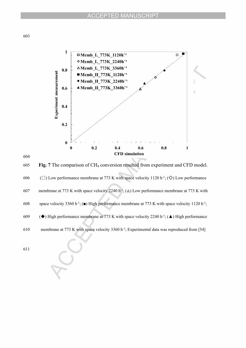
605 Fig. 7 The comparison of CH4 conversion resulted from experiment and CFD model.
606 (□) Low performance membrane at 773 K with space velocity 1120 h-1; (◇) Low performance
607 membrane at 773 K with space velocity 2240 h-1; (△) Low performance membrane at 773 K with
608 space velocity 3360 h-1; (■) High performance membrane at 773 K with space velocity 1120 h-1;
609 (◆) High performance membrane at 773 K with space velocity 2240 h-1; (▲) High performance
610 membrane at 773 K with space velocity 3360 h-1; Experimental data was reproduced from [54]
611
ACCEPTED MANUSCRIPT
612
613 Fig. 8 CH4 conversion of membrane reactor and sorption enhanced membrane reactor
614 under different space velocities. (■) Sorption enhanced membrane reactor under 1120 h-1; (□)
615 Simple membrane reactor under 1120 h-1; (◆) Sorption enhanced membrane reactor under 2240 h-
616 1; (◇) Simple membrane reactor under 2240 h-1; (▲) Sorption enhanced membrane reactor under
617 3360 h-1; (△) Simple membrane reactor under 3360 h-1.
618
ACCEPTED MANUSCRIPT
619
620 Fig. 9 The distribution of CO2 molar fraction in membrane reactor and sorption-
621 enhanced membrane reactor at the 100th sec.
622
623
624 Fig. 10 The distribution of water gas shift reaction rate in membrane reactor and
625 sorption enhanced membrane reactor at the 100th sec.
626
ACCEPTED MANUSCRIPT
627
628 Fig. 11 The distribution of CO molar fraction in membrane reactor and sorption
629 enhanced membrane reactor at the 100th sec.
630
631
632 Fig. 12 The distribution of methane steam reforming rate in membrane reactor and
633 sorption enhanced membrane reactor at the 100th sec.
634
ACCEPTED MANUSCRIPT
635
636 Fig. 13 The distribution of H2 molar fraction in membrane reactor and sorption
637 enhanced membrane reactor at the 100th sec.
638
ACCEPTED MANUSCRIPT
639640 Fig. 14. The variations of CO2 fraction, WGS rate, CO fraction, MSR rate and H2 641 fraction along a line from inlet to outlet. (a) the location of the line to extract these 642 variables, from (6.625×10⁻³ m, 0 rad, 0 m) to (6.625×10⁻³ m, 0 rad, 8×10⁻² m) in 643 cylindrical coordinate; (b) CO2 molar fraction; (c) water gas shift reaction rate; (d) 644 CO molar fraction; (e) methane steam reforming reaction rate; (f) H2 molar fraction.
ACCEPTED MANUSCRIPT
645
646 Fig. 15 Predicted performance of SEMR at different conditions. (a) CH4 conversion at different
647 space velocities (S/C=3; P=3 Bar); (b) H2 generation rate at different space velocities (S/C=3; P=3
648 Bar); (c) H2 yield within 3 mins at different space velocities (S/C=3; P=3 Bar); (d) CH4
649 conversion at different pressures (S/C=3; SV=3360 s-1); (e) H2 generation rate at different
650 pressures (S/C=3; SV=3360 s-1) and (f) H2 yield within 3 mins at different pressures (S/C=3;
651 SV=3360 s-1).
ACCEPTED MANUSCRIPT
Highlights Sorption enhanced membrane reactor was proposed to enhance H2 yield. H2 permeation and CO2 capture interacted with methane steam reforming. Validated CFD model assessed the enhancements of methane steam reforming. Na2ZrO3 sorbents significantly increased the H2 yield and CH4 conversion. CO poisoning to palladium membrane was also minimized by CO2 removal.
Related Documents