Proc. Indian Acad. Sci. (Earth Planet. Sci.), Vol. 95, No. 3, November 1986, pp. 321-330. Printed in India. Computation of synthetic seismograms for plane layered earth models including absorption and dispersion phenomena K N S YADAV and AVADH RAM Department of Geophysics, Banaras Hindu University, Varanasi 221 005, India MS received 30 May 1983; revised 15 November 1984 Abstract. A computer program package has been written in FORTRAN-IV language and tested successfullyon an ICL 1904Scomputer. This program enables one to compute synthetic seismograms for layered earth models. The provision for studying the effect of absorption and dispersion of seismic waves has been made with Subroutines. The present program utilizes eight Subroutines and requires about 35 K core memory. A set of examples are illustrated for absorption and dispersion models. An exponential decay of amplitude has been used for the absorption model. This method is based on the plane wave propagation in a flat-layered earth system. Normal incident P-waves are used to eliminate the effect of other phases. Change in shape of reflected waves is observed in absorption model due to damping of energy of higher frequencies. Lack of resolution is found between closelyspaced reflections at higher frequencies. The effect of dispersion on seismic waves decreases the time of primary reflections as well as amplitudes of the seismic waves. Keywords. Synthetic seismograms; computer programs; absorption; dispersion. 1. Introduction The problem of wave propagation from a seismic source in a layered medium can be addressed either through ray theory methods or by using wave theory approach. In the latter approach a direct numerical evaluation of integral representing the frequency domain solution is required. In this domain, approximate computational methods have been developed by Pinnery (1965), Fuchs (1968), Fuchs and Muller (1971), Bouchon and Aki (1977) and Bouchon (1979) and have introduced the concept of a discretized wave field to obtain the solution in the near field of the source. In the past, a number of techniques for computation of synthetic seismograms have been developed (Wuenschel 1960; Trorey 1962; Claerbout 1968; Trietal and Robinson 1966; Robinson 1968; Robinson and Trietal 1977; Khattri et al 1978; Kennet and Kerry 1979;Kennet 1980; Kennet and Illingworth 1981). They have considered different phenomena associated with the earth's crust. In most of these cases, effects of seismic energy loss have been ignored, but Trorey (1962) introduced an approach which allowed the inclusion of attenuation. Khattri et al (1978) considered the frequency-dependent absorption and velocity free from dispersion. Acoustic wave propagation in porous media has been studied by several workers (Biot 1962 a, b; Deresiewicz and Rice 1962, 1964; Deresiewicz and Levv 1967; Deresiewicz 1974 and Burridge and Vargas 1979). Dcrcsicwlcz (1974) showed that the presence of liquid in the pores causes a decrease in the phase velocity and motion is attenuated. More recently, there has been considerable interest for problems of absorption and dispersion. Ganley (1981) considered such 321

Welcome message from author
This document is posted to help you gain knowledge. Please leave a comment to let me know what you think about it! Share it to your friends and learn new things together.
Transcript
Proc. Indian Acad. Sci. (Earth Planet. Sci.), Vol. 95, No. 3, November 1986, pp. 321-330. �9 Printed in India.
Computation of synthetic seismograms for plane layered earth models including absorption and dispersion phenomena
K N S Y A D A V and A V A D H RAM Department of Geophysics, Banaras Hindu University, Varanasi 221 005, India
MS received 30 May 1983; revised 15 November 1984
Abstract. A computer program package has been written in FORTRAN-IV language and tested successfully on an ICL 1904S computer. This program enables one to compute synthetic seismograms for layered earth models. The provision for studying the effect of absorption and dispersion of seismic waves has been made with Subroutines. The present program utilizes eight Subroutines and requires about 35 K core memory. A set of examples are illustrated for absorption and dispersion models. An exponential decay of amplitude has been used for the absorption model. This method is based on the plane wave propagation in a flat-layered earth system. Normal incident P-waves are used to eliminate the effect of other phases. Change in shape of reflected waves is observed in absorption model due to damping of energy of higher frequencies. Lack of resolution is found between closely spaced reflections at higher frequencies. The effect of dispersion on seismic waves decreases the time of primary reflections as well as amplitudes of the seismic waves.
Keywords. Synthetic seismograms; computer programs; absorption; dispersion.
1. Introduct ion
The problem of wave propagation from a seismic source in a layered medium can be addressed either through ray theory methods or by using wave theory approach. In the latter approach a direct numerical evaluation of integral representing the frequency domain solution is required. In this domain, approximate computational methods have been developed by Pinnery (1965), Fuchs (1968), Fuchs and Muller (1971), Bouchon and Aki (1977) and Bouchon (1979) and have introduced the concept of a discretized wave field to obtain the solution in the near field of the source. In the past, a number of techniques for computation of synthetic seismograms have been developed (Wuenschel 1960; Trorey 1962; Claerbout 1968; Trietal and Robinson 1966; Robinson 1968; Robinson and Trietal 1977; Khattri et al 1978; Kennet and Kerry 1979;Kennet 1980; Kennet and Illingworth 1981). They have considered different phenomena associated with the earth's crust. In most of these cases, effects of seismic energy loss have been ignored, but Trorey (1962) introduced an approach which allowed the inclusion of attenuation. Khattri et al
(1978) considered the frequency-dependent absorption and velocity free from dispersion. Acoustic wave propagation in porous media has been studied by several workers (Biot 1962 a, b; Deresiewicz and Rice 1962, 1964; Deresiewicz and Levv 1967; Deresiewicz 1974 and Burridge and Vargas 1979). Dcrcsicwlcz (1974) showed that the presence of liquid in the pores causes a decrease in the phase velocity and motion is attenuated. More recently, there has been considerable interest for problems of absorption and dispersion. Ganley (1981) considered such
321
322 K N S Yadav and A vadh Ram
problems and gave a method to generate synthetic seismograms which incorporate these effects. His technique can be used to produce normal incidence, plane wave seismograms for fiat-layered earth models. It is essentially a modification of communication theory approach to synthetic seismograms.
In this article, we have developed a set of computer programs for the computation of synthetic seismograms based on the theory proposed by Ganley (1981) as it is straightforward and includes the effect of absorption and dispersion. These seismograms are useful in the study of effect of changes in lithology. This program contains eight Subroutines which are listed with their functions in table 1. Input and output of the Subroutines are given in table 2. This program requires 35 K core memory for the type of cases taken up in the present study. The program has been tested on an ICL 1904S computer. We have presented the results of an assumed model which contains sandy oil, gas and water overlain and underlain by shale to form a trap. Bed rock is assumed to be sandstone as a lower half space. In computation, an unit spike is taken as a signal and source-receivers configuration is assumed at the surface.
2. Computational procedure
Our programming formulation has been taken from the method given by Ganley (1981). The computation of synthetic seismograms is based on the well-known absorption model of exponential decay of amplitude with distance which is given by;
A = A0exp( - az) (1)
where A0 is the initial amplitude and A, the amplitude at depth z, t~ the absorption coefficient which is frequency-dependent, usually written as
o~ = Iwl/2cQ, (2)
where I w] is the absolute angular frequency, c the phase velocity and Q the quality factor.
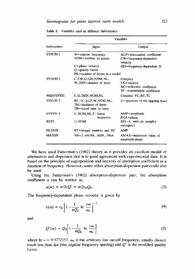
Table 1. List of Subroutines required for the computation of synthetic seismograms.
Subroutines Function
SYNTH 1 SYNTH 2
WIDSYNTH
SYNTH 3
SYNTH 4
REFL NLOGN MAXSN
Calculates attenuation, velocity and quality factor as a function of frequency. Makes velocity complex function of frequency and computes reflection and transmission coefficients, using output of SYNTH 1. Computes reflection and transmission coefficients without considering the frequency effect. Computes spectrum of upgoing and downgoing waves using output from SYNTH 2/WlDSYNTH. Computes synthetic seismograms on the basis of spectrum obtained from SYNTH 3. Provides complex conjugate to use in NLOGN Subroutine. Performs the Fourier transformation. Finds the maximum value to normalize the desired output.
Seismograms for plane layered earth models
Table 2. Variables used in different Subroutines.
323
Variables
Subroutines Input Output
SYNTH 1 W=angular frequency ALP=attenuation coefficient NOM=number of po in t s CW=frequency-dependent
velocity C=phase velocity QD=frequency-dependent Q Q=quality factor NL=number of layers in a model
SYNTH 2 C,CW,Q,QD,NOM,NL, W,DEN=density of layer
WIDSYNTH C,Q,DEN,NOM,NL
SYNTH 3 RC,TC,ALP,W,NOM,NL, TH=thickness of layer TR=travel time in layer
SYNTH 4 U,NOM,NL,F=Iinear AMP=amplitude frequency. PHA=phase
REFL U,NOM RF(=U with its complex conjugate)
NLOGN NT=integer number and RF AMP MAXSN NN=2 xNOM, AMP, PHA XMAX=maximum value of
amplitude/phase
Complex VC=velocity RC=reflection coefficient TC=transmission coefficient Complex VC,RC,TC U=spectrum of the upgoing wave
We have used Futterman's (1962) theory as it provides an excellent model of attenuation and dispersion that is in good agreement with experimental data. It is based on the principle of superposition and linearity of absorption coefficient as a function of frequency. However, some other absorption-dispersion pair could also be used.
Using the Futterman's (1962) absorption-dispersion pair, the absorption coefficient a can be written as,
a(w) = w/2cQ' = w/2coQo. (3)
The frequency-dependent phase velocity is given by
and
1 v~o ]-1 c(~o) = Co l-----A-- In - - (4)
rr~do O9o J
1 va~] Q' (w) = Q0 1 - ~--Q0 In oJ0 (5)
where In v = 0.5772157. to 0 is the arbitrary low cut-off frequency, usually chosen much less than Aw (the angular frequency spacing) and Q' is the modified quality factor.
324 K N S Yadav and Avadh Ram
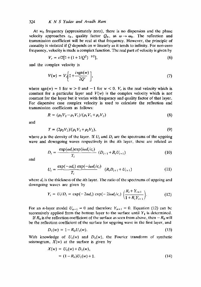
At w0 frequency (approximately zero), there is no dispersion and the phase velocity approaches Co, quality factor Q0, as to ~ too. The reflection and transmission coefficient will be real at that frequency. However, the principle of causality is violated if Q depends on w linearly as it tends to infinity. For non-zero frequency, velocity is made a complex function. The real part of velocity is given by
Vr = c/2[1 + (1 + 1/Q2)-1/2], (6)
and the complex velocity is
V ( w ) = Vr[l +isgn(w) ] (7)
where sgn(w) = 1 for w > 0 and - 1 for w < 0. Vr is the real velocity which is constant for a particular layer and V(w) is the complex velocity which is not constant for the layer but it varies with frequency and quality factor of that layer. For dispersive case complex velocity is used to calculate the reflection and transmission coefficients as follows:
R = (p2V2 - Pl V1) / (Pl VI q- p2V2) (8)
and
T = (2pzV2)/(p1V~ + peV2), (9)
where p is the density of the layer. If Ui and Di are the spectrums of the upgoing wave and downgoing waves respectively in the ith layer, these are related as
exp(adi)exp(itodi/ci) D i = (Di+ 1 + RiU/+I) (10)
Ti and
e x p ( - c~di) exp(-itodi/ci) U i = (RiOi+ 1 + U/+I) (11)
Ti
where ds is the thickness of the ith layer. The ratio of the spectrums of upgoing and downgoing waves are given by
Y; = Ui/Di = exp(-2t~di)exp(-2i todi /c i ) (_Ri+ ri+, i \1 + RiYi+t ]" (12)
For an n-layer model Un+ 1 = 0 and therefore Yn+l = 0. Equation (12) can be successively applied from the bottom layer to the surface until Y~ is determined.
If R0 is the reflection coefficient of the surface as seen from above, then - Ro will be the reflection coefficient of the surface for upgoing wave in the first layer, and
D,(w) = 1-noVa(w). (13)
With knowledge of Ul(w) and Dl(w), the Fourier transform of synthetic seismogram, X(w) at the surface is given by
X(w) = Ul(W) + Ol(w),
= (1 -R,,)O,(w) + 1. (14)
Seismograms for plane layered earth models 325
Therefore, given an n-layer model, it is possible to calculate the Fourier transform (FI') of the surface synthetic seismogram for an initial downgoing spike at the surface. This FT can then be multiplied by the FT of the wavelet if we wish to use a wavelet different from a spike as the input wavelet.
We have developed computer programs based on the above equations. Part-wise calculations are performed using different Subroutines (table 1). Subroutine SYNTH 1 calculates the attenuation coefficient, frequency-dependent velocity and modified quality factor depending on equations (3), (4) and (5). Subroutine SYNTH 2 first makes the velocity as a complex function, then reflection and transmission coefficients are calculated for dispersive case using (6) to (9).
We have also computed synthetic seismograms without the effect of dispersion. For this purpose, a separate Subroutine WlDSYNTH is developed. After computations of reflection and transmission coefficients of different layers, we have calculated the ratio of the spectrum of the upgoing and downgoing waves with the help of Subroutine SYNTH 3, which is based on (12). Surface layer synthetic seismograms in frequency domain are computed using (13) and (14). This is performed in Subroutine SYNTH 4. Time domain synthetic seismograms are computed using Subroutine NLOGN. Subroutine REFL is used to find out the complex conjugate of the frequency function, calculated only at positive frequencies. Maximum values of the amplitude and phases are obtained with Subroutine MAXSN, which are used to normalize the output.
3. Examples of synthetic seismograms
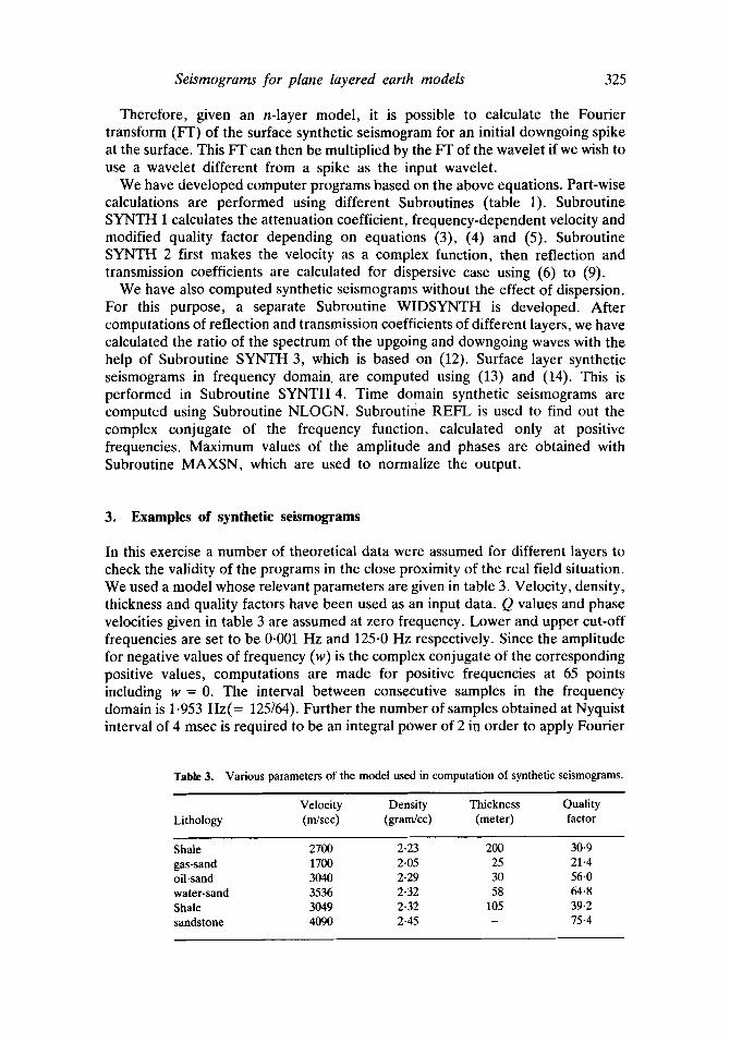
In this exercise a number of theoretical data were assumed for different layers to check the validity of the programs in the close proximity of the real field situation. We used a model whose relevant parameters are given in table 3. Velocity, density, thickness and quality factors have been used as an input data. Q values and phase velocities given in table 3 are assumed at zero frequency. Lower and upper cut-off frequencies are set to be 0.001 Hz and 125.0 Hz respectively. Since the amplitude for negative values of frequency (w) is the complex conjugate of the corresponding positive values, computations are made for positive frequencies at 65 points including w = 0. The interval between consecutive samples in the frequency domain is 1.953 Hz(= 125764). Further the number of samples obtained at Nyquist interval of 4 msec is required to be an integral power of 2 in order to apply Fourier
Table 3. Various parameters of the model used in computation of synthetic seismograms.
Velocity Density Thickness Quality Lithology (m/sec) (gram/cc) (meter) factor
Shale 2700 2-23 200 30-9 gas-sand 1700 2.05 25 21.4 oil-sand 3040 2.29 30 56.0 water-sand 3536 2.32 58 64.8 Shale 3049 2-32 105 39.2 sandstone 4090 2.45 - 75-4
326 K N S Yadav and Avadh Ram
Transform in our case for time domain calculation. The number of samples in both frequency and time domains should be equal. Thus it yields 128(= 27 ) samples in both the domains.
3.1 Non-dispersive model
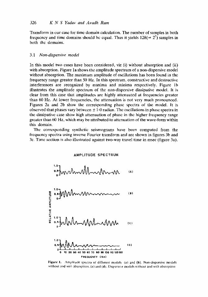
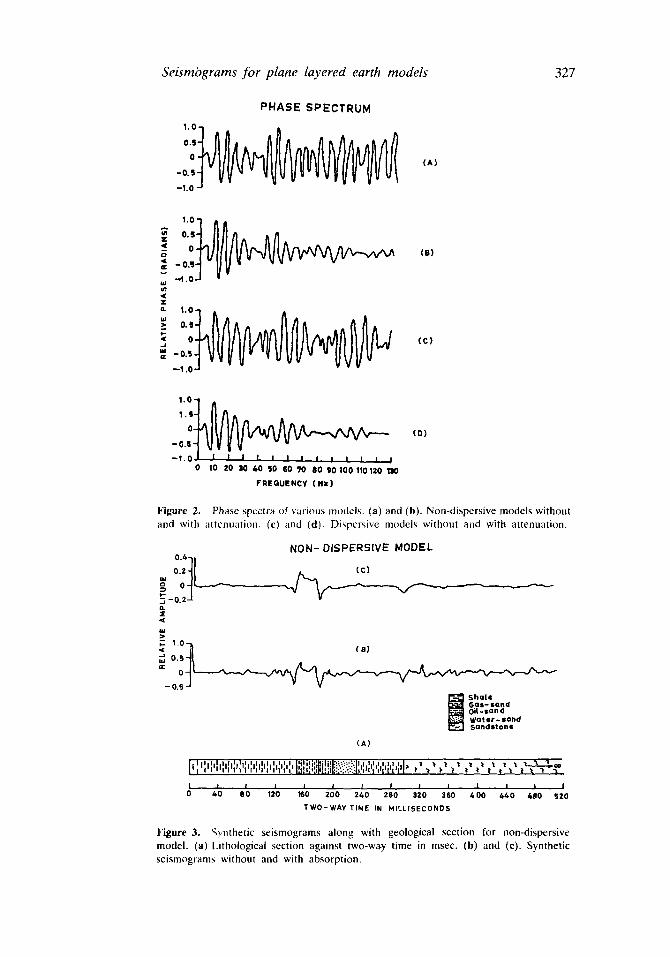
In this model two cases have been considered, viz (i) without absorption and (ii) with absorption. Figure la shows the amplitude spectrum of a non-dispersive model without absorption. The maximum amplitude of oscillations has been found in the frequency range greater than 50 Hz. In this spectrum, constructive and destructive interferences are recognized by maxima and minima respectively. Figure lb illustrates the amplitude spectrum of the non-dispersive dissipative model. It is clear from this case that amplitudes are highly attenuated at frequencies greater than 60 Hz. At lower frequencies, the attenuation is not very much pronounced. Figures 2a and 2b show the corresponding phase spectra of the model. It is observed that phases vary between + 1-0 radian. The oscillations in phase spectra in the dissipative case show high attenuation of phase in the higher frequency range greater than 60 Hz, which may be attributed to attenuation of the wave-form within this domain.
The corresponding synthetic seismograms have been computed from the frequency spectra using inverse Fourier transform and are shown in figures 3b and 3c. Time section is also illustrated against two-way travel time in msec (figure 3a).
AMPLITUDE SPECTRUM
O.S O
(A)
) -
_1
r
0.5
0
0.5
0
(B)
(c)
0.5 ( 0 )
0 I O 10 20 30 40 50 60 70 80 90 100 110 120 130
FREGUENCY (Hz )
F igure I . Amplitude spectra of differenl models (a) and (b). Non-dispersive models wJlhoul alld wilh absorption. (c) and (d). l)isperslxe models without and with absorption
Seismograms for plane layered earth models
PHASE SPECTRUM
1 . 0 ~
O.S 0
-OS -110
(A)
327
O.S
< 0 (el
--1.
<
- - O . S
o (c ) - 0 5
--1 i0
1.S
0
-O,S
- I . 0 0 10 20 30 40 50 60 70 80 g0100110120 110
FREQUENCY (Hz)
(D)
Figure 2. Phase spcctr+~ of v+~rious models. (a) and (b)+ Non-dispersive models without and with ~lttcnuation. (c) and (d). Dispersive modcls without and with attenuation.
NON- DISPERSIVE MODEL
(c) 0.4 o
~-0. 0. ~E
>-
+ ~ I
0.5-
~ O- -0.5-
(s)
~ Sholl Golf- SOlid Oil- san d Water-sand Sandstoflr
(A)
I ' ; "li "".+." : : J I l'+ t l + Z a . ~ . ~ . ~
t + ,. , . . + + I ' ' ' ' , ' 0 40 SO 120 160 200 240 ZEO 320 360 400 4.40 &SO 5ZO
TWO-WAY TIME IN MILLISECONDS
Figure 3, qynthetic seismograms along with geological section for non-dispersive model. (a) Lithological section against two-w++y time in msec. (b) and (c), Synthetic seismograms without and with absorption.
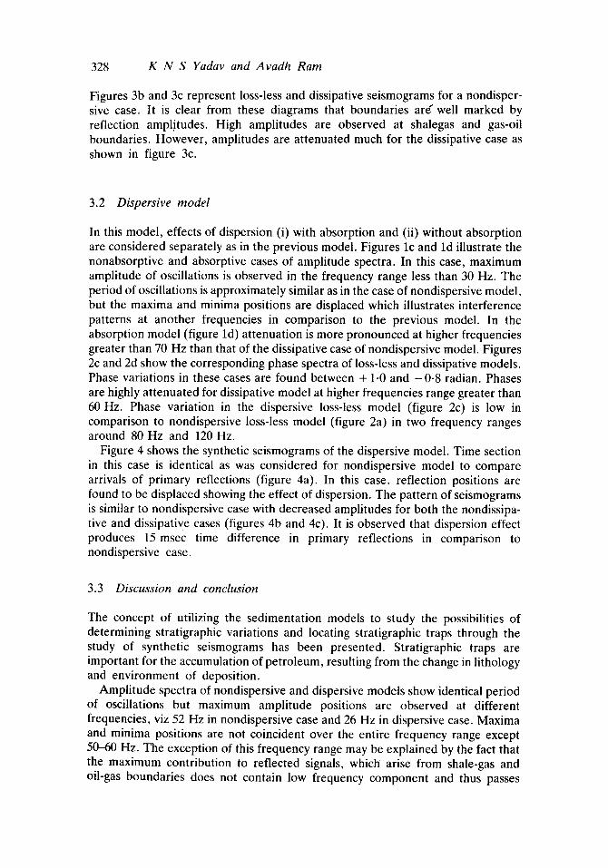
328 K N S Yadav and Avadh Ram
Figures 3b and 3c represent loss-less and dissipative seismograms for a nondisper- sive case. It is clear from these diagrams that boundaries are" well marked by reflection amplitudes. High amplitudes are observed at shalegas and gas-oil boundaries. However, amplitudes are attenuated much for the dissipative case as shown in figure 3c.
3.2 Dispersive model
In this model, effects of dispersion (i) with absorption and (ii) without absorption are considered separately as in the previous model. Figures lc and ld illustrate the nonabsorptive and absorptive cases of amplitude spectra. In this case, maximum amplitude of oscillations is observed in the frequency range less than 30 Hz. The period of oscillations is approximately similar as in the case of nondispersive model, but the maxima and minima positions are displaced which illustrates interference patterns at another frequencies in comparison to the previous model. In the absorption model (figure ld) attenuation is more pronounced at higher frequencies greater than 70 Hz than that of the dissipative case of nondispersive model. Figures 2c and 2d show the corresponding phase spectra of loss-less and dissipative models. Phase variations in these cases are found between + 1.0 and - 0 . 8 radian. Phases are highly attenuated for dissipative model at higher frequencies range greater than 60 Hz. Phase variation in the dispersive loss-less model (figure 2c) is low in comparison to nondispersive loss-less model (figure 2a) in two frequency ranges around 80 Hz and 120 Hz.
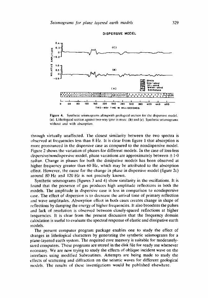
Figure 4 shows the synthetic seismograms of the dispersive model. Time section in this case is identical as was considered for nondispersive model to compare arrivals of primary reflections (figure 4a). In this case, reflection positions are found to be displaced showing the effect of dispersion. The pattern of seismograms is similar to nondispersive case with decreased amplitudes for both the nondissipa- tive and dissipative cases (figures 4b and 4c). It is observed that dispersion effect produces 15 msec time difference in primary reflections in comparison to nondispersive case.
3.3 Discussion and conclusion
The concept of utilizing the sedimentation models to study the possibilities of determining stratigraphic variations and locating stratigraphic traps through the study of synthetic seismograms has been presented. Stratigraphic traps are important for the accumulation of petroleum, resulting from the change in lithology and environment of deposition.
Amplitude spectra of nondispersive and dispersive models show identical period of oscillations but maximum amplitude positions are observed at different frequencies, viz 52 Hz in nondispersive case and 26 Hz in dispersive case. Maxima and minima positions are not coincident over the entire frequency range except 50-60 Hz. The exception of this frequency range may be explained by the fact that the maximum contribution to reflected signals, which arise from shale-gas and oil-gas boundaries does not contain low frequency component and thus passes
Seismograms for plane layered earth models 329
DISPERSIVE MODEL
. : : t { x
' . 0 1
( C )
- - x . / "
i s )
S h a l e G a l l -sand Oi l - sand
( A ) W a t e r - sand Sandstone
~ l I , I I I ! I I I " i ' : ' : ' ~ " : I I I ) �9 I I �9 I " ' , ' , , , , • , ,, ' , , ' , , ' , : ,: .~,,, ,L:.-:::!I ' , , ' , ' , , , , ' , , , '1~ ~ , ' , ' , t , ' , ' , ' , , . , , , , - - i - r ~
I . ~ I I I / I I I I I 1 I I 0 4 0 8 0 120 100 200 2 4 0 280 320 3~0 4 0 0 4&O 4.110
T W O - W A Y TIME IN k I I L L I S E C O N O S
Figure 4. Synthetic seismograms alongwith geological section for the dispersive model. (a). Lithological section against two-way time in msec. (b) and (c). Synthetic seismograms without and with absorption.
through virtually unaffected. The closest similarity between the two spectra is observed at frequencies less than 8 Hz. It is clear from figure 1 that absorption is more pronounced in the dispersive case as compared to the nondispersive model. Figure 2 shows the variation of phases for different models. In the case of loss-less dispersive/nondispersive model, phase variations are approximately between __+ 1.0 radian. Change in phases for both the dissipative models has been observed at higher frequency greater than 60 Hz, which may be attributed to the absorption effect. However, the cause for the change in phase in dispersive model (figure 2c) around 80 Hz and 120 Hz is not precisely known.
Synthetic seismograms (figures 3 and 4) show similarity in the oscillations. It is found that the presence of gas produces high amplitude reflections in both the models. The amplitude in dispersive case is less in comparison to nondispersive case. The effect of dispersion is to decrease the arrival time of primary reflection ~md wave amplitudes. Absorption effect in both cases creates change in shape of reflections by damping the energy of higher frequencies. It also broadens the pulses and lack of resolution is observed between closely-spaced reflections at higher frequencies. It is clear from the present discussion that the frequency domain calculation is useful to evaluate the spectral response of elastic and dissipative earth models.
The present computer program package enables one to study the effect of changes in lithological characters by generating the synthetic seismograms for a plane-layered earth system. The required core memory is suitable for moderately- sized computers. These programs are stored in the disk file for ready use whenever necessary. We are now trying to study the effects of oblique incident wave on the interfaces using modified Subroutines. Attempts are being made to study the effects of scattering and diffraction on the seismic waves for different geological models. The results of these investigations would be published elsewhere.
330 K N S Yadav and Avadh Ram
Acknowledgements
The authors are thankful to the Director, KDM IPE, Oil and Natural Gas Commission, Dehradun for financial assistance.
References
Biot. M A 1962a J. Appl. Phys. 33 1482 Biot M A 1962b J. Accoust. Soc. Am. 34 1256 Bouchon M 1979 J. Geophys. Res. 84 3609 Bouchon M and Aki K 1977 Bull. Seism. Soc. Am. 67 259 Claerbout J F 1968 Geophysics 33 264 Burridge R and Vargas C A 1979 Geophys. J. R. Astron. Soc. 58 61 Deresiewicz H 1974 Bull. Seismol. Soc. Am. 64 1901 Deresiewicz H and Levy A 1967 Bull. Seismol. Soc. Am. 57 381 Deresiewicz H and Rice J T 1962 Bull. Seismol. Soc. Am. 52 595 Deresiewicz H and Rice J T 1964 Bull. Seismol. Soc. Am. 54 409 Fuchs K 1968 J. Phys. Earth 16 27 Fuchs K and Muller G 1971 Geophys. J. R. Astron. Soc. 28 417 Futterman W I 1962 J. Geophys. Res. 69 5279 Ganley D C 1981 Geophysics 46 1100 Kennet B L N 1980 Geophys. J. R. Astron. Soc. 61 1 Kennet B L N and Iilingworth M R 1981 Geophys. J. R. Astron. Soc. 66 633 Kennet B L N and Kerry N J 1979 Geophys. J. R. Astron. Soc. 57 557 Khattri K, Gaur V K, Mittal R and Tandon A K 1978 Geoexploration 16 185 Pinnery R A 1965 J. Geophys. Res. 70 5107 Robinson E A 1968 Geophysics 33 521 Robinson E A and Trietal S 1977 Geophys. Prosp. 25 434 Trietal S and Robinson E A t966 Geophysics 31 17 Trorey A W 1962 Geophysics 27 766 Wuenschel P C 1960 Geophysics 25 106
Related Documents